Q16pro Gen2 1U - Router RGBlink - Free user manual and instructions
Find the device manual for free Q16pro Gen2 1U RGBlink in PDF.


| Product Type | Professional Video Router |
| Brand | RGBlink |
| Model | Q16pro Gen2 1U |
| Form Factor | 1U Rackmount |
| Dimensions (W x H x D) | 482 x 44 x 320 mm |
| Weight | 5 kg |
| Power Supply | AC 100-240V, 50/60Hz, 50W |
| Input Ports | 16 x SDI/HDMI/Other (configurable) |
| Output Ports | Multiple SDI/HDMI outputs |
| Video Formats Supported | SD/HD/3G-SDI, up to 4K |
| Control Interface | Ethernet, RS-232, Front Panel, Web GUI |
| Switching Speed | Frame-accurate (<1 field) |
| Redundant Power Supply | Optional |
| Cooling | Fan, front-to-back airflow |
| Operating Temperature | 0°C to 40°C |
| Storage Temperature | -20°C to 60°C |
| Humidity | 10% to 90% non-condensing |
| Safety Compliance | CE, FCC, RoHS |
| Cleaning Instructions | Use a dry, soft cloth; avoid liquids. |
| Spare Parts & Repairability | Contact RGBlink support; modular design. |
Frequently Asked Questions - Q16pro Gen2 1U RGBlink
User questions about Q16pro Gen2 1U RGBlink
0 question about this device. Answer the ones you know or ask your own.
Ask a new question about this device
Download the instructions for your Router in PDF format for free! Find your manual Q16pro Gen2 1U - RGBlink and take your electronic device back in hand. On this page are published all the documents necessary for the use of your device. Q16pro Gen2 1U by RGBlink.
USER MANUAL Q16pro Gen2 1U RGBlink
natural_image
Abstract network diagram with interconnected nodes and circles (no text or labels)Article No: RGB-RD-UM-Q16pro Gen2 1U E00 Revision No: V1.3
Content
Declarations 2
FCC/Warranty 2
Operators Safety Summary ....3
Installation Safety Summary ....3
Chapter 1 Your Product ....5
1.1 In the Box....5
1.2 Product Overview....6
1.2.1 Rear Panel....7
1.2.2 Front Panel....8
1.2.3 Dimension 9
Chapter 2 Install Your Product....10
2.1 Plug in Signals 10
2.2 Plug in Main Power 10
2.3 Turn on Your Product....10
Chapter 3 Use Your Product....11
3.1 Use the Menu Button....11
3.2 Menu Structure 11
3.3 Use the Menu 12
3.3.1 Presentation.... 12
3.3.2 Split 14
3.3.3 Advanced....15
3.3.4 Save Preset.... 16
3.3.5 Load Preset....17
3.3.6 System....18
3.4 XPOSE 2.0 Installation....20
3.5 XPOSE Operation 23
3.5.1 Login in XPOSE 23
3.5.2 System Setting 24
3.5.3 Output | Input | Overview 28
3.5.4 Display Management....32
3.5.5 Layer Management....35
3.5.6 Preset Management 39
Chapter 4 Order Codes....41
4.1 Product Codes....41
4.2 Module Codes....41
4.2.1 Input Modules 41
4.2.2 Output Modules 41
Chapter 5 Support ....42
5.1 Contact Us....42
Chapter 6 Appendix....43
6.1 Terms & Definitions....43
6.2 Revision History 50
Thank you for choosing our product!
This User Manual is designed to show you how to use this video processor quickly and make use of all the features. Please read all directions and instructions carefully before using this product.
Declarations
FCC/Warranty
Federal Communications Commission (FCC) Statement
This equipment has been tested and found to comply with the limits for a class A digital device, pursuant to Part 15 of the FCC rules. These limits are designed to provide reasonable protection against harmful interference when the equipment is operated in a commercial environment. This equipment generates, uses, and can radiate radio frequency energy and, if not installed and used in accordance with the instruction manual, may cause harmful interference to radio communications. Operation of this equipment in a residential area may cause harmful interference, in which case the user will be responsible for correcting any interference.
Guarantee and Compensation
RGBlink provides a guarantee relating to perfect manufacturing as part of the legally stipulated terms of guarantee. On receipt, the purchaser must immediately inspect all delivered goods for damage incurred during transport, as well as for material and manufacturing faults. RGBlink must be informed immediately in writing of any complains.
The period of guarantee begins on the date of transfer of risks, in the case of special systems and software on the date of commissioning, at latest 30 days after the transfer of risks. In the event of justified notice of compliant, RGBlink can repair the fault or provide a replacement at its own discretion within an appropriate period. If this measure proves to be impossible or unsuccessful, the purchaser can demand a reduction in the purchase price or cancellation of the contract. All other claims, in particular those relating to compensation for direct or indirect damage, and also damage attributed to the operation of software as well as to other service provided by RGBlink, being a component of the system or independent service, will be deemed invalid provided the damage is not proven to be attributed to the absence of properties guaranteed in writing or due to the intent or gross negligence or part of RGBlink.
If the purchaser or a third party carries out modifications or repairs on goods delivered by RGBlink, or if the goods are handled incorrectly, in particular if the systems are commissioned operated incorrectly or if, after the transfer of risks, the goods are subject to influences not agreed upon in the contract, all guarantee claims of the purchaser will be rendered invalid. Not included in the guarantee coverage are system failures which are attributed to programs or special electronic circuitry provided by the purchaser, e.g. interfaces. Normal wear as well as normal maintenance are not subject to the guarantee provided by RGBlink either.
The environmental conditions as well as the servicing and maintenance regulations specified in this manual must be complied with by the customer.
Operators Safety Summary
The general safety information in this summary is for operating personnel.
Do Not Remove Covers or Panels
There are no user-serviceable parts within the unit. Removal of the top cover will expose dangerous voltages. To avoid personal injury, do not remove the top cover. Do not operate the unit without the cover installed.
Power Source
This product is intended to operate from a power source that will not apply more than 230 volts rms between the supply conductors or between both supply conductor and ground. A protective ground connection by way of grounding conductor in the power cord is essential for safe operation.
Grounding the Product
This product is grounded through the grounding conductor of the power cord. To avoid electrical shock, plug the power cord into a properly wired receptacle before connecting to the product input or output terminals. A protective-ground connection by way of the grounding conductor in the power cord is essential for safe operation.
Use the Proper Power Cord
Use only the power cord and connector specified for your product. Use only a power cord that is in good condition. Refer cord and connector changes to qualified service personnel.
Use the Proper Fuse
To avoid fire hazard, use only the fuse having identical type, voltage rating, and current rating characteristics. Refer fuse replacement to qualified service personnel.
Do Not Operate in Explosive Atmospheres
To avoid explosion, do not operate this product in an explosive atmosphere.
Installation Safety Summary
Safety Precautions
For all device installation procedures, please observe the following important safety and handling rules to avoid damage to yourself and the equipment.
To protect users from electric shock, ensure that the chassis connects to earth via the ground wire provided in the AC power Cord.
The AC Socket-outlet should be installed near the equipment and be easily accessible.
Unpacking and Inspection
Before opening device shipping box, inspect it for damage. If you find any damage, notify the shipping carrier immediately for all claims adjustments. As you open the box, compare its contents against the packing slip. If you find any shortages, contact your sales representative.
Once you have removed all the components from their packaging and checked that all the listed components are present, visually inspect the system to ensure there was no damage during shipping. If there is damage, notify the shipping carrier immediately for all claims adjustments.
Site Preparation
The environment in which you install your device should be clean, properly lit, free from static, and have adequate power, ventilation, and space for all components.
Chapter 1 Your Product
1.1 In the Box
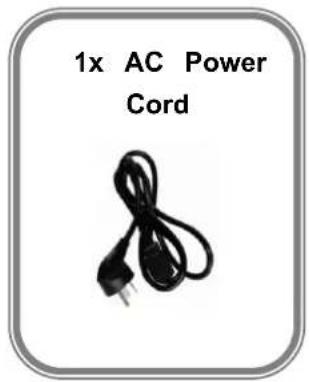
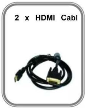
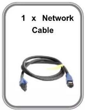
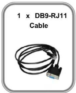
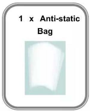
Note: AC Power Cable supplied as standard according to destination market.
1.2 Product Overview
Q16pro Gen2 1U adopts modular design, which supports up to 8 inputs, including quad HDMI 1.3, quad DVI, quad SD/HD/3G SDI, dual HDMI 2.0 & dual DP 1.2, dual HDMI 1.3 & dual DVI, single H.264/265 for 2K and 4K signals; 4 outputs, with dual HDMI 2.0, dual DP 1.2, quad HDMI 1.3, quad DVI, quad SDI signals optional.
The standard unit comes with 4 HDMI 1.3 outputs and builds with local front control panel and remote control interfaces with RS 232 and Ethernet ports.
Q16pro Gen2 1U is available to be remote controlled by XPOSE or 3rd party APP / controller by open API.
Q16pro Gen2 1U combines rugged design, class-leading video processing and image quality, ultra-low latency, versatile 4K connectivity, livestreaming capabilities, and unmatched ease of use to meet the requirement of the modern commercial display systems application, including live corporate meetings, hybrid events, worship productions, or large-scale LED video wall installations.
Its 8 layers with roaming capacity and layer can cross over each output without layer counting up.
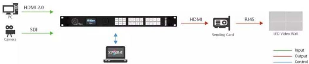
flowchart
graph LR
    PC["PC"] -->|HDMI 2.0| Server["Server"]
    Camera["Camera"] -->|SDI| Server
    Server -->|HDMI| SendingCard["Sending Card"]
    SendingCard -->|RJ45| LED["LED Video Wall"]
    X703E["X703E"] <-->|Signal| X703E
    style X703E fill:#f9f,stroke:#333
    style Input stroke:#000,stroke-width:2px
    style Output stroke:#000,stroke-width:2px
    style Control stroke:#000,stroke-width:2px
Q16pro Gen2 1U System Connection Diagram
1.2.1 Rear Panel
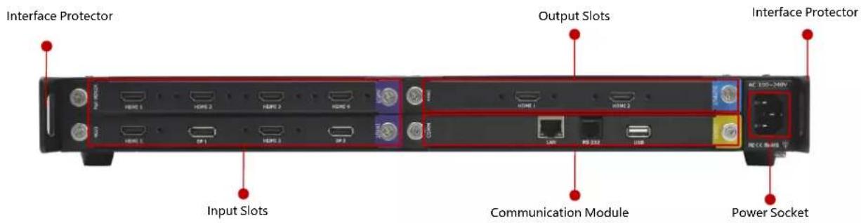
| Name | Description |
| Input Slots | Support quad HDMI 1.3, quad DVI, quad 3G SDI, dual HDMI 1.3 & dual DVI, dual HDMI 2.0 & dual DP 1.2, single IP and other optional input modules[TYSY] le tip indicates input |
| Output Slots | Support quad HDMI 1.3, quad DVI, quad SDI, dual HDMI 2.0, dual DP 1.2 and other optional output modules tip indicates output tip indicates output |
| Communication Module | 1xLAN、1xRS 232、1xUSB w tip indicates communication w tip indicates communication |
| Power Module | 1×IEC power socket |
| Interface Protector | Used to pull out device, fix cables and protect interfaces from collision |
1.2.2 Front Panel
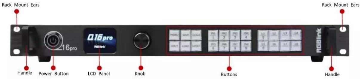
| Name | Description |
| Power Button | Press the button to power on or power off the device.Button light turns red when powered on. |
| LCD Panel | Display current status of the device, and provide interactive choices in conjunction with buttons on the front panel. |
| Knob | Rotate the knob to select a item.Press the knob to confirm the operation. |
| Buttons | MENU: 1) Enter main menu; 2) Back to the previous menu.SAVE: Push SAVE+Digital Button to save scenes to SCENE1-16.SCALE: Adjust width、height、H position and V position of layers.SPLIT: Select layout for Split Mode.LOAD: Push LOAD+Digital Button to load scenes from SCENE 1-16LAYOUT: Select layout for Presentation Mode.IN1-IN8: 1) Input signal selection buttons; 2) 1, 2, 3, 4, 6, 7, 8, 9 digital button.L1-L8: 1) Layer selection buttons; 2) L1 and L5 can also be used a 0 digital button respectively. |
| Handles | For carrying device. |
| Rack Mount Ears | Use with the load-bearing screws to fix device on the rack. |
1.2.3 Dimension
Following is the dimension of Q16pro Gen2 1U for your reference:
Dimension: 490mm x 363.2mm x 55mm
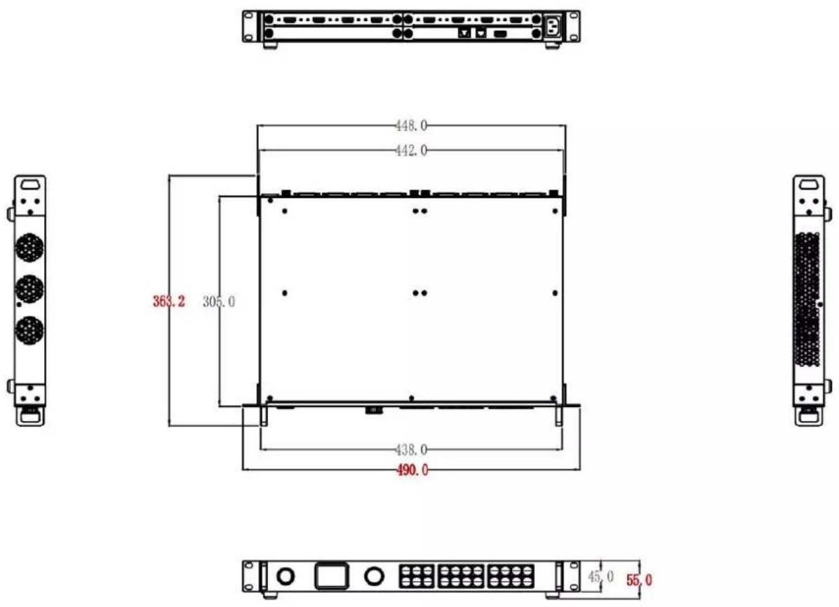
unit: mm
Chapter 2 Install Your Product
2.1 Plug in Signals
Connect signals to the input connector of device (ensure all devices are powered off first). Tighten connector screws/locks where provided.
2.2 Plug in Main Power
Connect IEC cable to device and plug into wall socket. Turn on power at wall socket.
2.3 Turn on Your Product
After the device is boot up, the screen shows as below, meanwhile the screen will show its input and output state and IP address.
Users can check input and output status by rotating the black knob, as shown in the figure below.
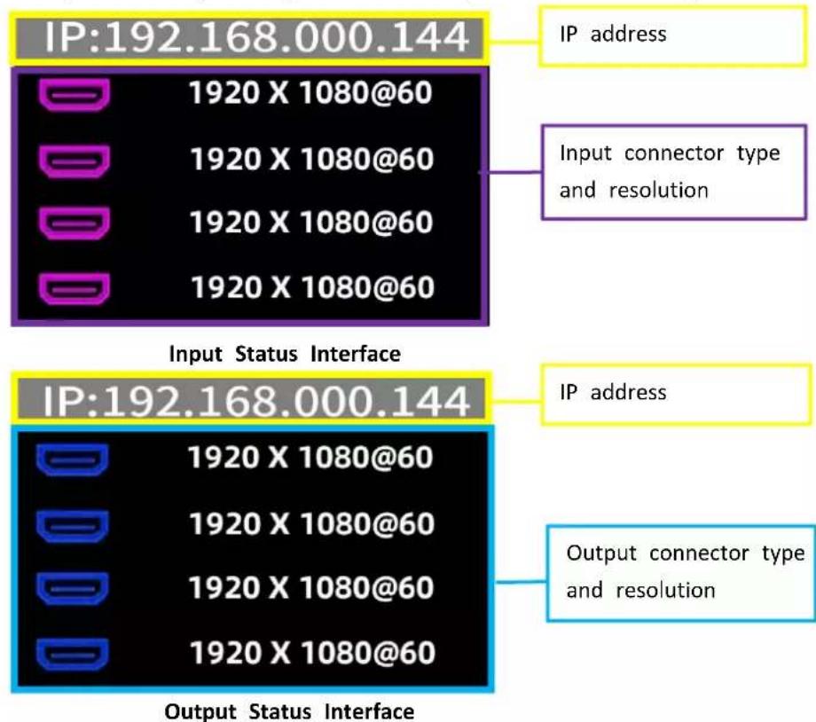
Note: 1. IP address defaults to 192.168.0.100;
2. purple icon indicates input, blue icon indicates output. Pictures above take HDMI input and output status as the example.
Chapter 3 Use Your Product
3.1 Use the Menu Button
Push【MENU】button to enter main menu.
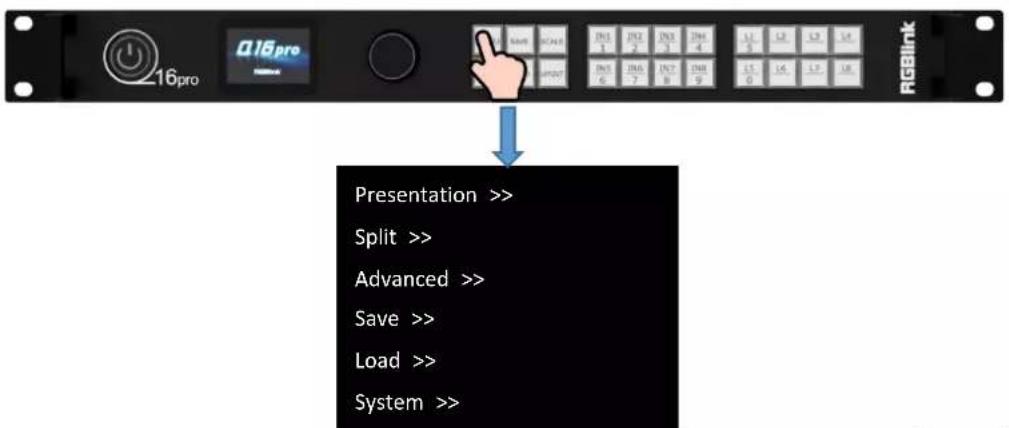
Turn the knob to select corresponding menu item; push the knob to enter sub-menu; push【MENU】button to return back to the previous menu.
1) The symbol >> indicates that the next item is available, shown as Figure 1;
2) The symbol -> indicates that the item is editable, shown as Figure 2;
3) Push the knob to edit the item. The symbol * indicates the selected item is under editing state, ready to be set or checked, shown as Figure 3.
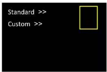
Figure 1
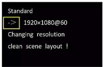
Figure 2
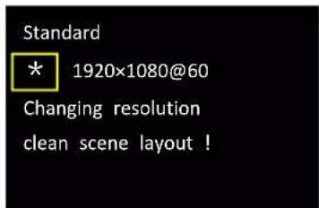
Figure 3
3.2 Menu Structure
The MENU structure includes Presentation, Split, Advanced, Scene Save, Scene Load and System, shown in the figure below.
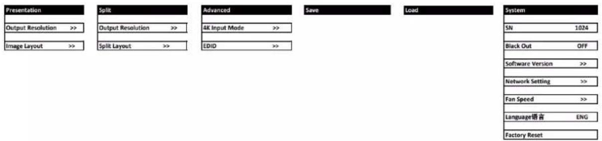
3.3 Use the Menu
Use the menu system for convenient and intuitive operation. The LCD panel shows the menu items. The screen will show the default state when the menu is not in use, or the operation has timed out.
Using the MENU button and rotary knob in the front panel, the screen will show the corresponding menus according to user selections.
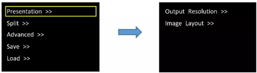
3.3.1 Presentation
After the device is boot up, push MENU to enter main menu interface. Then rotate the knob and select
flowchart
graph LR
    A["Presentation >>"] --> B["Output Resolution >>"]
    C["Split >>"] --> B
    D["Advanced >>"] --> B
    E["Save >>"] --> B
    F["Load >>"] --> B
Output Resolution
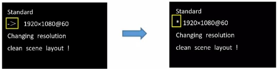
In Output Resolution interface, users can choose Standard resolution or Custom resolution.
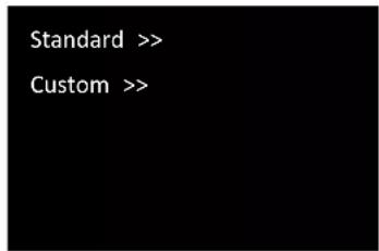
Standard: Push the knob to edit resolution. Wait the symbol -> in front of the resolution changes into symbol *, and then users can rotate the knob to choose standard resolution.
Custom: Push the knob to edit resolution. Wait the symbol -> in front of the resolution changes into symbol *.
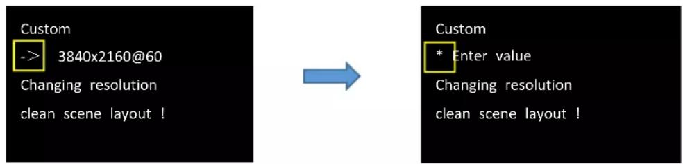
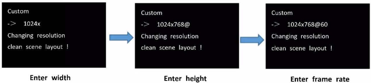
The 0\~9 numeric keys will light up at the same time. Use the numeric keys to input the width, height and frame rate.
After entering the width, press the knob to confirm and then enter the height; if height parameter is set, press the knob to enter the frame rate, as shown in the figures below.
flowchart
graph LR
    A["Custom --> 1024x<br>Changing resolution<br>clean scene layout !"] --> B["Custom --> 1024x768@<br>Changing resolution<br>clean scene layout !"]
    B --> C["Custom --> 1024x768@60<br>Changing resolution<br>clean scene layout !"]
After the width, height and frame rate are all set, push knob to confirm.
Image Layout
Select the image layout for presentation mode. There are 15 layout patterns built-in as follows:
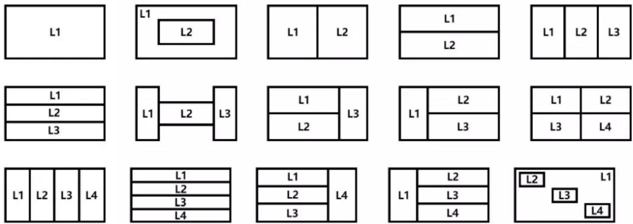
Push the knob to select layout, and the LCD Panel will automatically return to the previous menu interface. Users can use the L1-L8 buttons on the front panel to select the layer, and then select the input signal by using IN1- IN8 buttons.
Note: ONLY the first four layouts are available for 4K input module. Please reselect if the wrong layout is chosen
3.3.2 Split
After the device is boot up, push MENU to enter main menu interface. Then rotate the knob and select
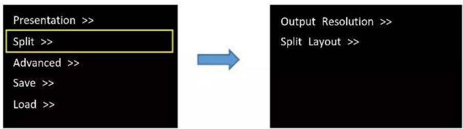
flowchart
graph LR
    A["Presentation >>"] --> B["Split >>"]
    B --> C["Advanced >>"]
    C --> D["Save >>"]
    D --> E["Load >>"]
    F["Output Resolution >>"] --> G["Split Layout >>"]
Output Resolution
The same operation as shown in Presentation.
Split Layout
There are 6 split modes available and each basic split mode comes with useful multi-picture layout.
| Split Mode | Background | Multi-Picture Layout | ||
| H 1/2 | 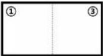 | 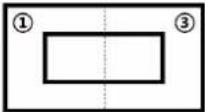 | 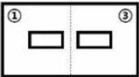 | 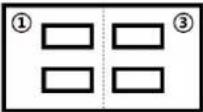 |
| V 1/2 | 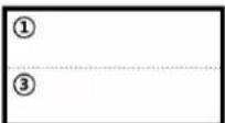 | 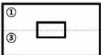 | 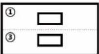 | 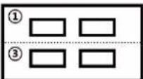 |
| Cross | 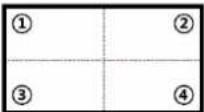 | 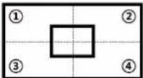 | 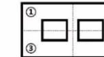 | 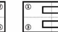 |
| H 1/4 | 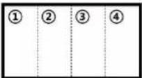 | 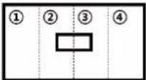 | 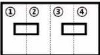 | |
| V 1/4 | 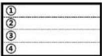 | 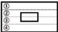 | 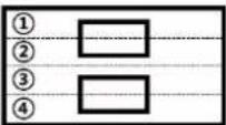 | |
H 1/3
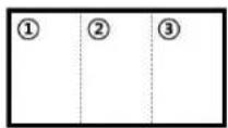
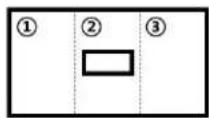
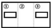
Choose the split mode from 6 types shown above by rotating the knob. Push the knob to select the multi-picture layout under this split mode and then set parameters.
The LCD screen displays as follows:
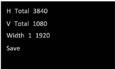
Set H total, V total, width1 of screen according to actual need.
For example: Set H total as 3840, V total as 1080, Height 1 is 1080, same with V total. Set Width 1 as 1920 and Width 2 will be 1920 (H total <3840> - Width 1 <1920> = Width 2 <1920>).
Use the numeric keys to enter parameters, then rotate the knob to "Save" and push the knob to save above settings.
Note: ONLY H 1/2 layout and V 1/2 layout are available for4K input module. Please reselect if the wrong layout is chosen.
3.3.3 Advanced
After the device is boot up, push MENU to enter main menu interface. Then rotate the knob and select
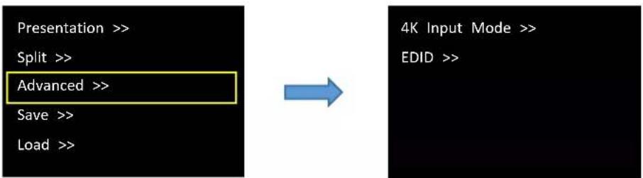
4K Input Mode
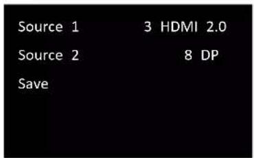
Source 1/Source 2: with HDMI 2.0, DP 1.2 input source available. The number indicates the position of this interface on the input module.
Rotate the knob to "Save" and push the knob to save above settings.
EDID
Input port 3 HDMI 2.0
Source CUSTOM
Input port: 1\~8 input port
Source: CUSTOM or RESET optional
Choose CUSTOM to custom EDID and the LCD panel displays the interface below.
Custom EDID
* Enter value
The 0\~9 numeric keys will light up at the same time. Use the numeric keys to enter the width, height and frame rate one by one and then push the knob to confirm.
Choose RESET to reset EDID and the LCD panel displays the interface below after successful setting.
Copy EDID success
Please reset layer
3.3.4 Save Preset
After the device is boot up, push MENU to enter main menu interface. Then rotate the knob and select
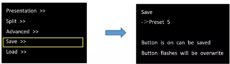
RGBlink provides 16 positions for saving or recording parameters.
Enter Save interface, the SAVE button light is on, which indicates the SAVE function is enabled.
Digital buttons 0-9 will be always on or flashing. An always-on button indicates that no preset has not been saved at this position; A flashing button indicates that certain preset has been saved at this position already.
Push the knob and wait the symbol -> in front of the Preset changes into symbol *. Users can turn the rotary knob to select Preset1-Preset16 or use the number button 1, 2, 3, 4, 5, 6, 7, 8, 9, 0 to select Preset1-Preset10. Select the position that will save, push the knob to confirm.
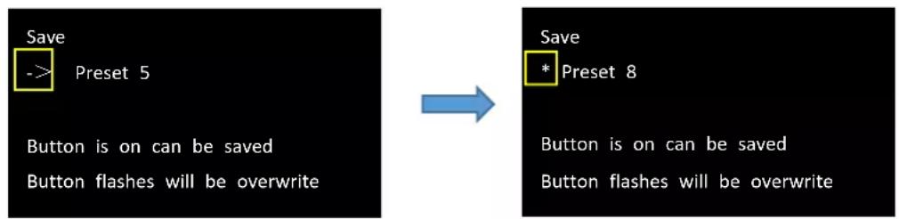
Saving preset in the button with flashing light will overwrite the saved parameters before.
For example: If button 8 is flashing, pushing button 8 will overwrite the preset saved in Preset 8, and the LCD screen will display as follows.
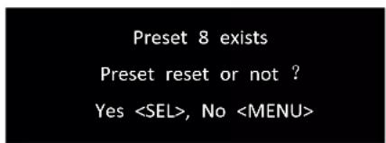
Push knob to confirm or MENU to cancel the operation.
3.3.5 Load Preset
After the device is boot up, push MENU to enter main menu interface. Then rotate the knob and select
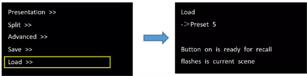
Enter Load interface, the LOAD button light is on, which indicates the LOAD function is enabled.
Digital buttons 0-9 will be always on or flashing. An always-on button indicates that certain preset has been saved at this position; A flashing button indicates that certain preset has been saved at this position already, which is ready for recall.
For example: If button 5 is flashing, it means that Preset 5 has been loaded. Now users need to load Preset 7, please do as follows: Push the knob and wait the symbol -> in front of the Preset changes into symbol *. Then push button 7 to load Preset7. Now the button 7 light starts flashing and button 5 light changes into always-on status.
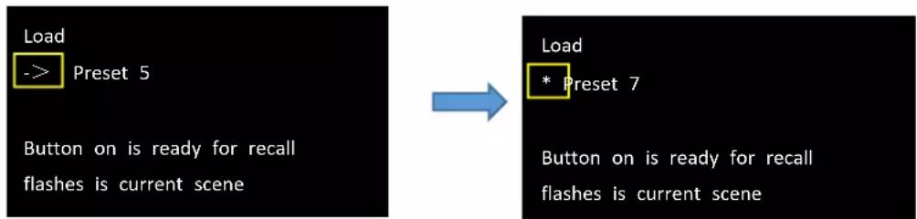
Then view the LCD screen to check if the operation is successful, if the above operation is ok, the screen will display as follows.
Load succeed
3.3.6 System
After the device is boot up, push MENU to enter main menu interface. Then rotate the knob and select
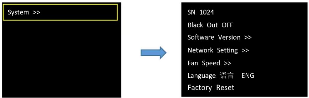
SN
To check serial number of the device.
Black Out
Q2 1U provides black effect processing for output with cut black effect, which can realize one-key-touch to a black screen. Rotate the knob to Black Out to turn on black effect processing.
Software Version
Rotate the knob to Software Version to check communication module version, input module version and output module version.
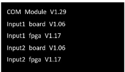
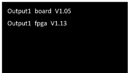
Network Setting
Rotate the knob to Network Setting.
DHCP OFF
IP Address >>
Net Mask >>
Gateway >>
MAC Address
DHCP: ON/OFF
Turn off DHCP to manually set IP Address, Subnet Mask and Gateway. The setting takes effect after the device is rebooted.
Fan Speed
Rotate the knob to Fan Speed so as to adjust fan speed for device dissipation.
Auto Control OFF Fan Speed 80%
Users can turn on Auto Control for automatic adjustment of fan speed or turn off Auto Control to adjust speed manually by rotating black knob on the front panel.
Language
Rotate the knob to Language to switch language here. English or Chinese available.
Factory Reset
Rotate the knob to Factory Reset and the LCD panel will show the interface below.
Factory reset or not
Yes<SEL>, No<MENU>
Select "YES" or "NO". Confirm by pushing knob to restore default settings, cancel by pushing MENU button.

Note: Choose factory reset will restore all parameters to the default settings, including but not P address, EDID, presets, etc. Users need to re-import configuration set before.
3.4 XPOSE 2.0 Installation
Environment Requirements:
Window
Processor: 1 GHz or above 32 bit or 64 bit processor
Memory: 4 GB or more
Graphics: Support Direct X9 128M or above (open AERO effect)
Hard disk space: Above 16G (primary partitions, NTFS format)
Monitor: Resolution must be 1920×1080 pixel or above(it can not display normally if the resolution is lower than 1920×1080)
Operating system: Windows 7 or above (full version, not Ghost version or compact version)
CPU: i5 and above
Mac
Monitor: Resolution must be 1680×1050 pixel or above (it can not display normally if the resolution is lower than 1680×1050)
CPU: i5 and above

XPOSESoft
-
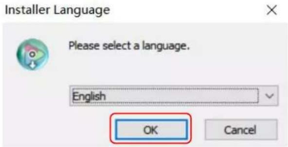
Double click, it will pop-up the installer language box, select the language, for example, select "English", and click "OK" to confirm.
-
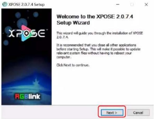
Click "Next" to install.
- Click "Browse..." to select the XPOSE software install location.
Click "Install".
- During installation, it will pop up the window of Install Shield Wizard for Virtual Com port.
5.Click "Next".
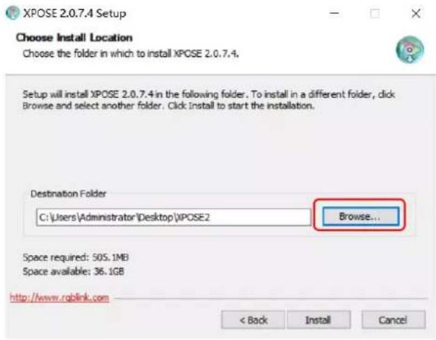
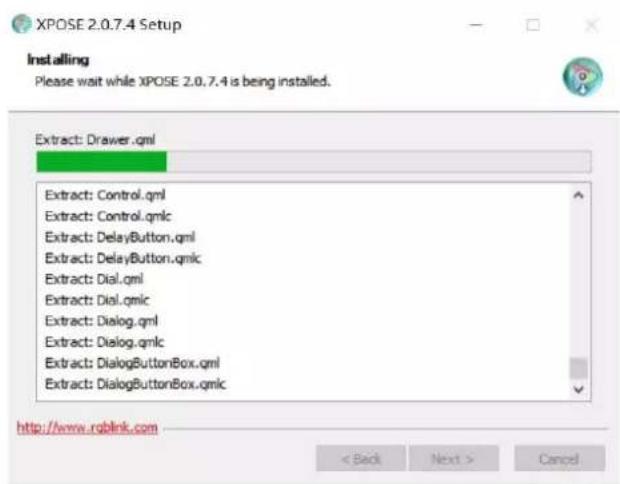
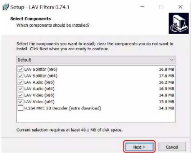
- Then click "Install", as shown in the figure.
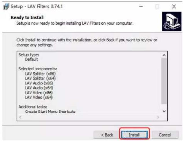
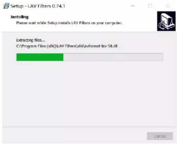
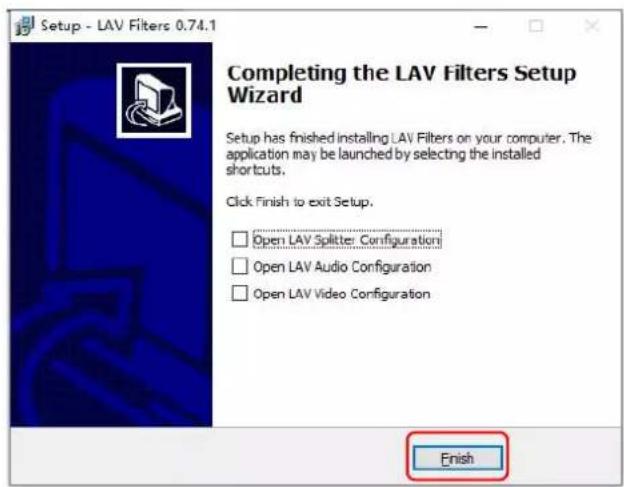
- Click "Finish" and complete the installation, as shown in the figure below.
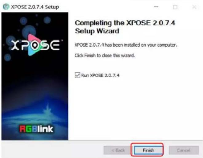
- Click "Finish" and is ready to run the XPOSE software
3.5 XPOSE Operation
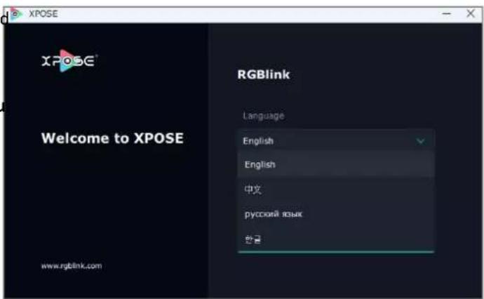
Double click this icon, and enter the log on interface shown in the right:
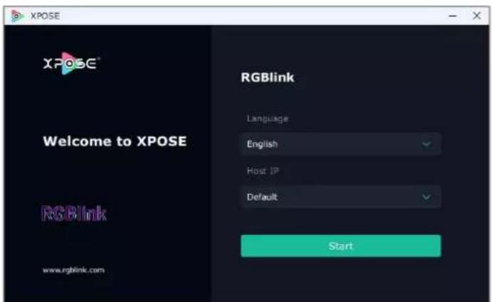
The initial language of XPOSE 2.0 is self adjusted based on the operation system language of the computer.
If you want to change language, just click Langu and choose one you need.
Then click Start to run XPOSE.
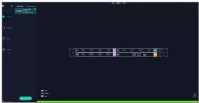
After login, the interface is shown in the right.
Users can find 5 major parts : System Setting, Connect, Display, Layer, Scenes.
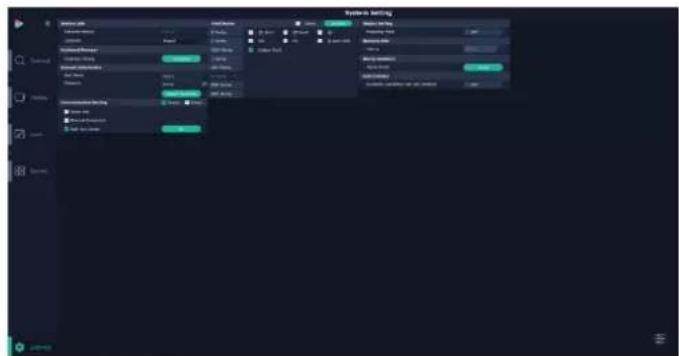
3.5.2 System Setting
Click to enter
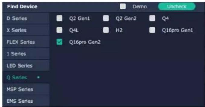
Find Device: New version of XPOSE 2.0 is bla default in Find Device. Users are supposed to choose correct series and then select the devi needed.
System Info: Check current software version and choose system language you need.

Keyboard Management: click
Keyboard Setting is designed to fit for different operation system such as Windows and Mac. Users can set short cut keys.
Drag Input, Output, Layer and Preset from the I to the keys you desired as shown in the figure:
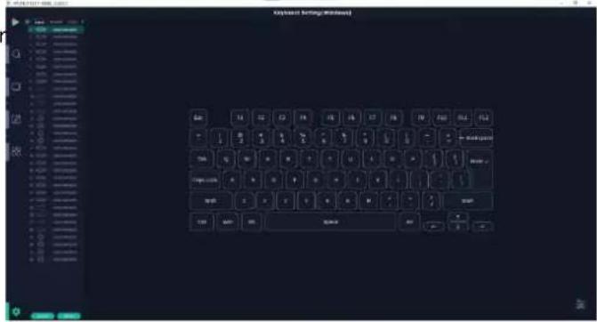
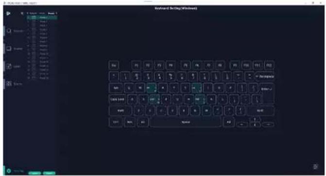
Please note the keyboard area where allows to set short cut keys.
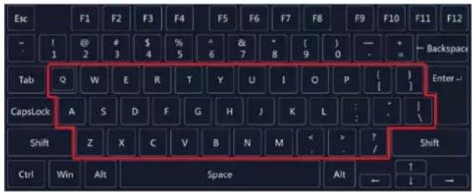
If the setting goes wrong or no need for short cu any more, click clear some keys or clear all.
Clear: is to clear some keys, the keys need to sel before hand.
Clear all: is to remove all already set short cut ke
Users can also Save The Keyboard Setting As Scri
Scrip Set
File Path: Save the current Keyboard Settings in the script to the local path File Name: script file name Load Script: Load/Delete
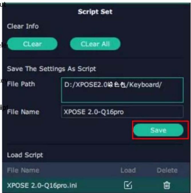
Click Return to back to
Communication Setting: The default is
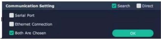
Serial Port: search only those connect via serial port Ethernet Connection: search only those connect via Ethernet.
Both Are Chosen: click both, both connections change synchronously.
Display Setting: Users can turn on Expanding Mode if there is an extension screen.

Novice Guide : check novice guide for quicker operation of XPOSE software.

Auto Connect: turn on auto connection switch and the interface will pop up a prompt to remind the whether to restore the previous interface.

Authorization Setting
Click to open up the authorization entry.
Authorization Setting is used to add and edit the user name and password for authorized users, as well as the permissions that users can operate.
Authorization Status defaults to OFF, please Turn Status for operation.
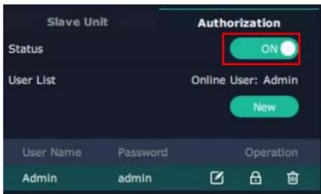
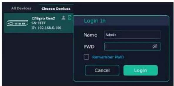
For operating device for the first time, or device upgrade, or factory reset, XPOSE defaults to log i Administrator with name defaults to Admin, and
PWD defaults to admin is displayed in Chosen Devices.
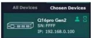
If users have logged in XPOSE before, is displayed in Chosen Devices. Enter Name and PWD, then click Login. icon indicates successful operation.
Click New in Authorization interface to add ne USER NAME and set PWD.
Then click Save to confirm.
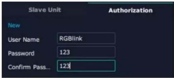
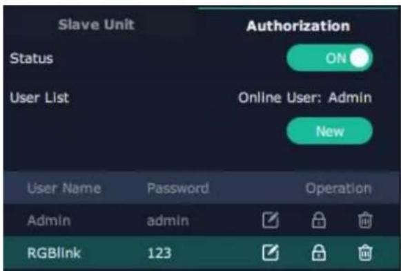
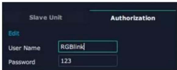
Edit: Edit user name and password already built.
Delete: Delete user name and password already built.
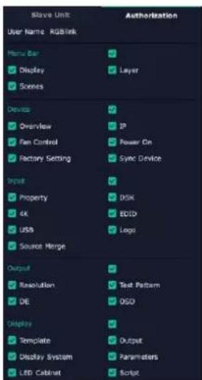
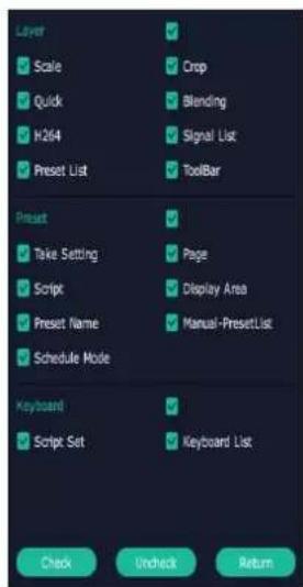
Authorization Set: Functions on XPOSE 2.0 on this computer that the users are allowed to operate.
Click the green block to remove the function i to be permitted.
Slave Unit:
Slave Unit is to control multiple devices simultaneous which are connected to same network. ("In the same network" means that the third section in the I address digits are the same)
XPOSE do operation on one device, same operation synchronized to other devices. For example, there is another device linked to the same network, one with 192.168.0.112, SN: 0027; the other with IP: 192.168.0.129, SN: 3344.
If users want the same operation on 3344 to be back up to 0027, please do as follows.
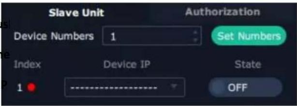
- Set device numbers;
- Select the IP of the device in the drop-down me for Device IP;
-
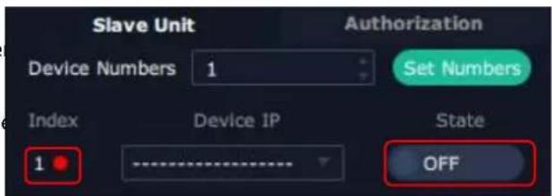
Click ON, the two device are connected when the
red pot turns to be a green one ; -
Click OFF to disconnect, it could not control two device at the same time.
3.5.3 Output | Input | Overview
Click to check rear panel interface as shown in the right figure.
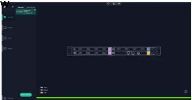
Note:
- purple tip indicates input, blue tip indicates output, yellow tip indicates communication.
- Interface Color Description: 1) Green: normal signal; 2) Yellow: abnormal signal; 3) White: no signal. (Due to hardware limitation, interface of SDI output module always displays white where there is or isn't a signal.)
Device Connection
-
Click the device needed in the
li -
Click in the
.
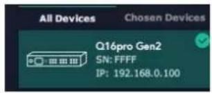
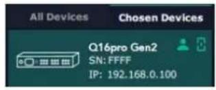
Output Setting
Click any output port, the board where the port locates is selected. Users can do settings to the now.
A red rectangle flashes around the chosen port when it is chosen.
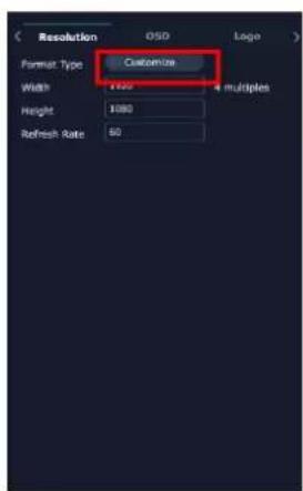
Resolution:
Q16pro Gen2 1U supports resolution settings of output modules.
Users can choose Standard Resolution or type in width, Height and Refresh Rate to Custom Resolution shown in the right figure.

natural_image
Front panel of a computer interface showing ports, connectors, and a highlighted button (no readable text or symbols)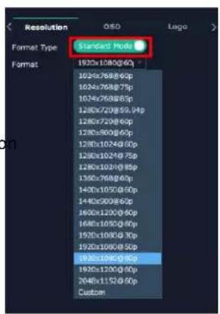
OSD:
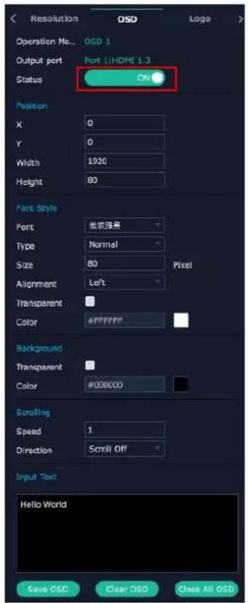
Q16pro Gen2 1U output modules which support OSD shown below: (Please Turn ON Status before setting)
*Quad HDMI 1.3 Output Module
*Quad SDI Output Module
*Quad DVI Output Module
Order Codes please refer to 4.2 Module Codes.
Output Port: current output port
Status: ON/OFF OSD
X/Y: the starting horizontal and vertical position
Width/Height: the horizontal and vertical size of the 1
Font: font of the text, all fonts installed in the computer are available
Font Type: Normal, Italic, Bold, Bold Italic
Font Size: 0-300 pixels
Alignment: set alignment type
Background: choose transparent or set background col
Scroll Speed: 0-16
Scroll Direction: Scroll Off, Scroll Left
Input Text: The exact content of the text
After setting, users choose Save OSD, Clear OSD (If the setting is not desired) or Close All OSD.
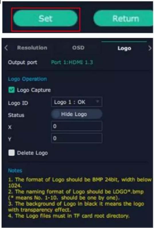
After all settings done, click
LOGO: Users need to pre-store the Logo on the SD card for Logo capture.
Output Port: current port
Logo Operation:
Logo Capture:
Logo ID: Load Logo ID been saved
Status: Hide/Show Logo
X/Y: Horizontal and vertical position of Logo
Delete Logo: Clear logo set already
Input Setting
Click any input port, the board where the port locates is selected. Users can do settings to the port now.
A red rectangle flashes around the chosen port when it is clicked.
User can set
< 4K > setting interface will appear.
4K
Input Module: Position of current chosen port Basic Parameters
Input Source: Choose certain port on the 4K module

natural_image
Front panel of a network device showing ports, connectors, and status LEDs (no readable text or symbols)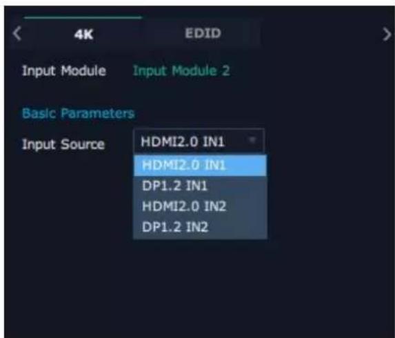
EDID
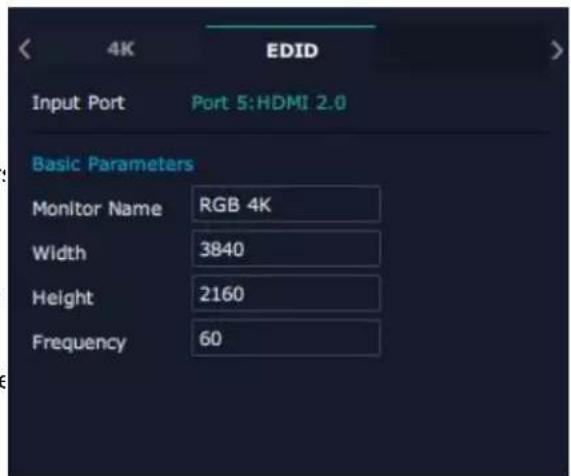
Input Port: chosen port
Basic Parameters:
Monitor Name: type the monitor name
Width/Height/Frequency: type in custom parameters to meet your needs.
Input modules which support EDID are as follows:
• Quad HDMI 1.3 Input Module
• Dual HDMI 2.0 & DP 1.2 4K@60 Input Module
- Quad DVI Input Module
Order Codes please refer to 4.2 Module Codes.
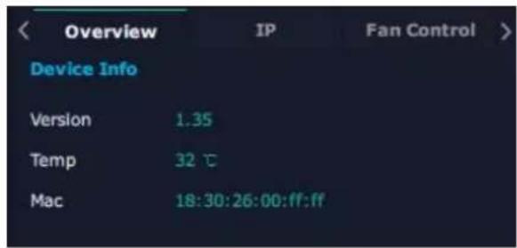
Overview
Click Return, there are Overview, IP, Fan Control, Factory Setting.
Device Info: users can check communication module version, current device temperature and MAC information.
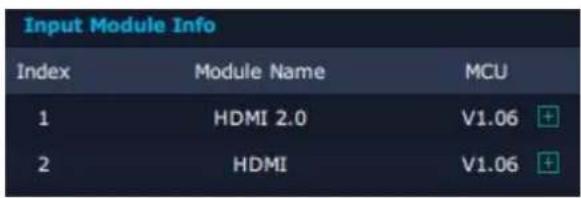
Input Module Info: users can check current input module name and MCU version
“...” indicates that there are no input modules, as shown in the right figure.
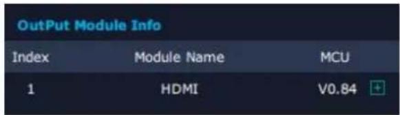
Output Module Info: users can check current output module name and MCU version
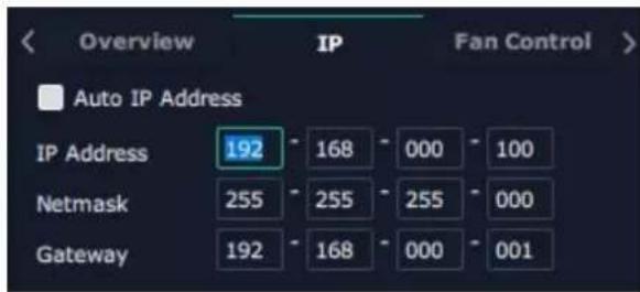
IP: support auto/manual setting. Show IP Address Netmask, Gateway
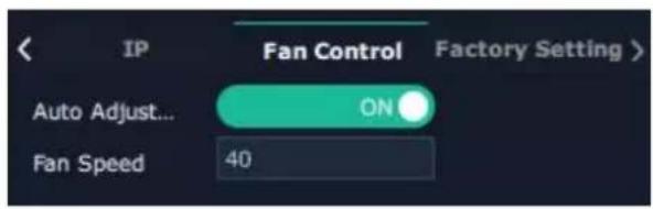
Fan Control: support auto/manual setting.
Fan Speed: 0-100 adjustable
Notice: To avoid insufficient heat dissipation, the recommended manual fan speed is not less than 30%.
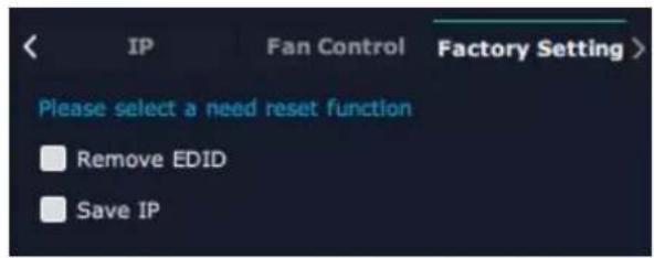
Factory Setting
Remove EDID: clear the previous EDID parameter
Save IP: no change of IP after reset
3.5.4 Display Management
Display System is for users to set layout of output
Click and then click to the interface.
Container:
Container here means the Display Area, for example it could be a formed LED screen or an array of LCDs.
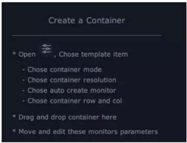
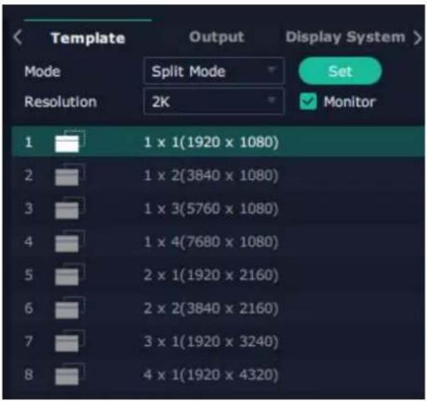
Template
There are 8 types of basic "Display Area", which are used to contain output interface, and could be regarded as output layout.
Drag a template to create a container (a display area)
Resolution
Choose monitor and then select output resolution.
Mode
Each mode is marked in different color and provided with fitted templates. Users can do operations like splice under different modes.
Q16pro Gen2 1U: Split Mode and Presentation Mode (by default) optional.
Presentation Mode: No need of recreating a container after changing resolution.

Presentation Mode
Split Mode: No container is reserved after change of resolution. Need of recreating a container.
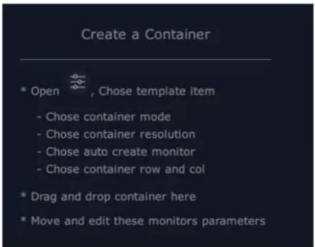
Split Mode
Customize Container
Click Customize at the bottom of
template list.
AOI Layout: Auto or Manual
Steps of creating container are as follows:
- Fill in H Total/V Total and Row/Column, it will calculate H item and V item automatically.
For example, if user needs to create a container with row and 4 columns and each display has a width of 1920 and a height of 1080, the total width will be and the total height will be 1080; - Click
, the container will display in the interface; - Click
to save the container.
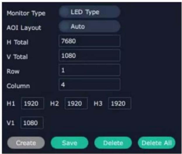
Container Adjustment
- Move: Drag the boarder of the display area to m its place in the interface.
- Scale: Click to shrink, click to enlarge the proportion of display area on interface.
- Cancel: Long pressing ✗ to cancel the screen group.

Display
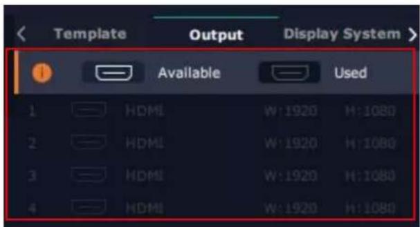
Output List:
White one: available
Gray one unavailable
Operation Steps:
Left-mouse click the output and drag it to the disp of the set container.
Replacement:
Drag and drop the output into the corresponding display. The output being replaced will turn from g to white in the list.
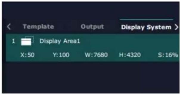
Display System
Q16pro Gen2 1U allows users to edit the name of
Display Area that has been created by clicking.
3.5.5 Layer Management
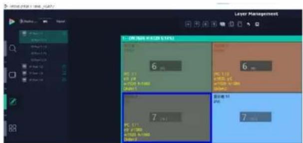
Layer Management is designed to manage the lay
of each monitor. Click to enter the interface.
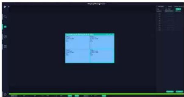
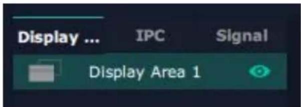
Display Area
When entering Layer Management interface, the window is blank. The screen group created in Display System shall be dragged from the Display Area.
IPC
IPC is short for IP Camera, that is, the signal of IP camera accessed through IP input module are displayed here.
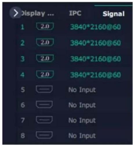
Signal
Signal list, showing all input signals and resolution: currently. Drag the signal to the display.
Click users can rename the input signal and then click to confirm.
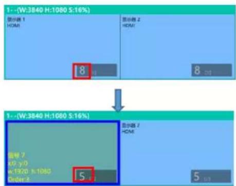
Layer
Layer number: The number in the red rectangle of the right figure represents the number of layers that can be placed at the output.
As signal source is dragged to the display, the number in the red rectangle reduces accordingly, a if layers have all been used up, the signal source cannot be dragged to this display anymore.
Note: One signal occupies one layer (4K signal occupies four layers), signal can be dragged into the container repeatedly.
Layer Adjustment:
There are two ways to adjust layer.

1. Use the bar under the interface
Choose one layer and the bar shows its signal source type in position and size. Click Set to confirm.
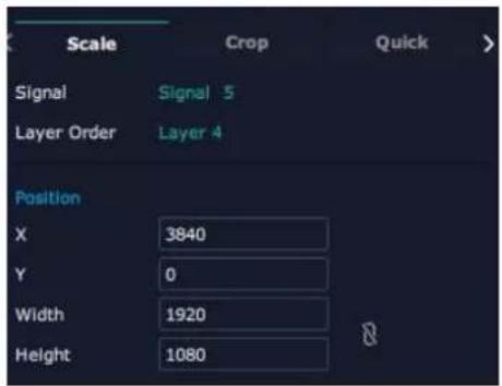
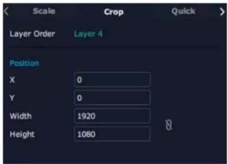
2. Layer Scale and Crop
Choose one layer needed to be adjusted, and type in position and size.

means data related, when width is changed, height be changed as same proportion.

means data not related, width and height need to d respectively.
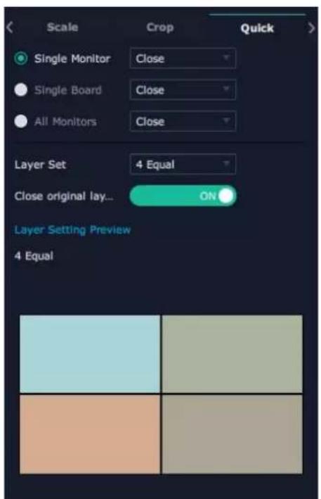
Quick
Quick is to set layer layout quickly.
- Single Monitor: choose one output port users need to set
- Single Board: choose one output module users need to set
- All Monitors: set close or on
- Layer Set: set layer layout
Users can drag and drop the source from the Signal Li
After setting, click
Layer Movement
Moving the mouse to drag the layer.
Layer Remove
Click the cross

on the top right of the layer to
remove the layer if needed.
Layer Set

lock the layer to prevent wrong operations.

max to cover up the monitor.

cover up all monitors in the same screen group
with the one signal.
Layer Copy
Press Ctrl and mouse left at the same time, move the mouse the layer selected can be copied and place in monitor in the same Display Area but it doesn't work when cross over display area.
Other Operation on Layer

Use the tools bar on top of window to do such operations
 | Layer Backward |  | Layer to Top |  | Paste Selected |
 | Layer Forward |  | Select All |  | Cancel Selected |
 | Layer to Bottom |  | Copy Selected |  | Delete Selected |
Notice: For modification of monitor where layer has been set, the monitor will display the input signal of the first interface by default.
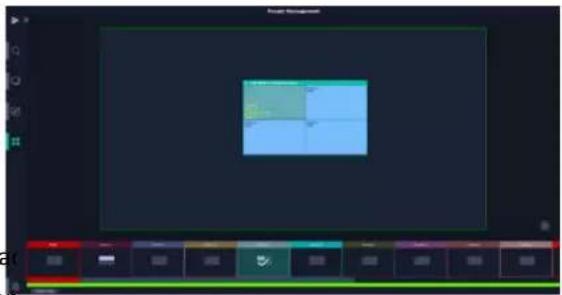
3.5.6 Preset Management
Preset Management is designed to switch bank and sa bank.
Preset Management Mode:
- Manual Mode 2. Schedule Mode
1. Manual Mode
The chosen scene will be displayed in the main interface and the PGM screen is in the first in the Bank Column
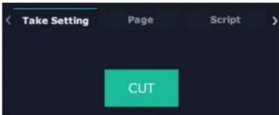
Cut
Cut, switch from PVW to PGM immediately.
Page
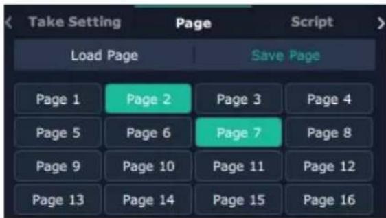
Save Page
Select a Preset, click Save Page, then choose Page and the Preset will be saved in this page. Page with saved preset displays in green.
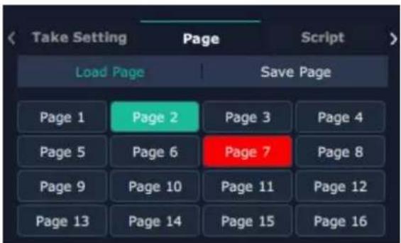
Load Page
Click Load Page, page with saved preset displays in green. Select one preset and then load this preset, page turns in red.
Script
Click
- Content
- Declarations 2
- Chapter 1 Your Product ....5
- Chapter 2 Install Your Product....10
- Chapter 3 Use Your Product....11
- XPOSE 2.0 Installation....20
- Chapter 4 Order Codes....41
- Chapter 5 Support ....42
- Chapter 6 Appendix....43
- Declarations
- FCC/Warranty
- Federal Communications Commission (FCC) Statement
- Guarantee and Compensation
- Operators Safety Summary
- Do Not Remove Covers or Panels
- Power Source
- Grounding the Product
- Use the Proper Power Cord
- Use the Proper Fuse
- Do Not Operate in Explosive Atmospheres
- Installation Safety Summary
- Safety Precautions
- Unpacking and Inspection
- Site Preparation
- Chapter 1 Your Product
- In the Box
- Product Overview
- Rear Panel
- Front Panel
- Dimension
- Chapter 2 Install Your Product
- Plug in Signals
- Plug in Main Power
- Turn on Your Product
- Chapter 3 Use Your Product
- Use the Menu Button
- Menu Structure
- Use the Menu
- Presentation
- Output Resolution
- Image Layout
- Split
- Split Layout
- Advanced
- 4K Input Mode
- EDID
- Save Preset
- Load Preset
- System
- SN
- Black Out
- Software Version
- Network Setting
- Fan Speed
- Language
- Factory Reset
- XPOSE 2.0 Installation
- Environment Requirements:
- Window
- Mac
- XPOSE Operation
- System Setting
- Scrip Set
- Authorization Setting
- Slave Unit:
- Output | Input | Overview
- Note:
- Device Connection
- Output Setting
- Resolution:
- OSD:
- Output Port: current port
- Logo Operation:
- Input Setting
- 4K
- Overview
- Factory Setting
- Display Management
- Container:
- Template
- Resolution
- Mode
- Customize Container
- Steps of creating container are as follows:
- Container Adjustment
- Display
- Output List:
- Operation Steps:
- Replacement:
- Display System
- Layer Management
- Display Area
- IPC
- Signal
- Layer
- Layer Adjustment:
- Use the bar under the interface
- Layer Scale and Crop
- Quick
- Layer Movement
- Layer Remove
- Layer Set
- Layer Copy
- Other Operation on Layer
- Preset Management
- Manual Mode
- Cut
- Page
- Save Page
- Load Page
- Script
- Preset Name
- Hotkey
- Schedule Mode
- Steps are as follows
- Product Codes
- Module Codes
- Input Modules
- Output Modules
- Chapter 5 Support
- Contact Us
- RGBlink Headquarters
- China Regional Sales & Support
- Beijing Region Office
- Europe Regional Sales & Support
- Chapter 6 Appendix
- Terms & Definitions
- Revision History
Brand : RGBlink
Model : Q16pro Gen2 1U
Category : Router