
MatrixPRO-II - Router Barco - Free user manual and instructions
Find the device manual for free MatrixPRO-II Barco in PDF.


| Product Type | DVI Digital Matrix Router |
| Brand | Barco |
| Model | MatrixPRO-II |
| Category | Router |
| Inputs | 16 DVI-D (single-link) on four 4-input cards |
| Outputs | 16 DVI-D (single-link) on four 4-output cards |
| Max Resolution | WUXGA 1920x1200 @ 60Hz |
| HDCP Support | Yes, per-input enable/disable |
| EDID Management | Default, Auto Mix, Output Copy, Resolution modes |
| Control Methods | Front panel, RS-232, Telnet, Web GUI, PC software (UDP/TCP) |
| Reference Output | Built-in video generator with test patterns |
| Monitoring Output | DVI output to monitor any input |
| Power Supply | Dual hot-swappable, 100-240 VAC, 50-60 Hz, 800W max each |
| Dimensions (H x W x D) | 7 x 17.32 x 14.96 in (178 x 440 x 380 mm), 4RU |
| Weight | < 10 kg (22 lb) |
| Operating Temperature | 0°C to 40°C (32°F to 104°F) |
| Humidity | 0-95% non-condensing |
| Firmware Update | Via RJ11 to DB9 cable using MegaBoot software |
| Warranty | 3 years parts and labor |
| Safety | Do not remove covers; proper grounding; use specified fuse |
| Compliance | FCC Class A, CE, China RoHS |
Frequently Asked Questions - MatrixPRO-II Barco
User questions about MatrixPRO-II Barco
0 question about this device. Answer the ones you know or ask your own.
Ask a new question about this device
Download the instructions for your Router in PDF format for free! Find your manual MatrixPRO-II - Barco and take your electronic device back in hand. On this page are published all the documents necessary for the use of your device. MatrixPRO-II by Barco.
USER MANUAL MatrixPRO-II Barco
natural_image
Black electronic device with labeled ports and a digital display showing network ports (no readable text or symbols beyond branding)Copyright © Bar•o. Mar•h 24, 2013
All rights reserved. No part of this document may be opied, reproduced or translated. It shall not otherwise be re-orded, transmitted or stored in a retrieval system without the prior written consent of Baro.
Noti•e
Bar•o provides this manual "as is" without warranty of any kind, expressed or implied, including but not limited to the implied warranties or merchantability and fitness for a particular purpose. Bar•o may make improvements and/or •hanges to the produ•t(s) and/ or the program(s) described in this publication at any time without notice.
This publication •ould •contain technical inaccuracy or typographic errors. Changes are periodically made to the information in this publication; these changes are incorporated in new editions of this publication.
Federal Communications (FCC) Statement
This equipment has been tested and found to •omply with the limits for a •class A digital device, pursuant to Part 15 of the FCC rules. These limits are designed to provide reasonable protection against harmful interference when the equipment is operated in a •ommerial environment. This equipment generates, uses, and •an radiate radio frequency energy and, if not installed and used in a••ordan•e with the instruction manual, may •ause harmful interference to radio •ommuniations. Operation of this equipment in a residential area may •ause harmful interference, in which •ase the user will be responsible for •orre•ting any interference.
Guarantee and Compensation
Baro provides a guarantee relating to perfect manufacturing as part of the legally stipulated terms of guarantee. On receipt, the purahaser must immediately inspect all delivered goods for damage incurred during transport, as well as for material and manufacturing faults Baro must be informed immediately in writing of any complaints.
The period of guarantee begins on the date of transfer of risks, in the •ase of special systems and software on the date of •ommissioning, at latest 30 days after the transfer of risks. In the event of justified notice of •ompliant, Bar•o •an repair the fault or provide a replacement at its own discretion within an appropriate period. If this measure proves to be impossible or unsus•essful, the pur•haser •an demand a reduction in the purchase price or •an•ellation of the •ontra•t. All other •claims, in particular those relating to •ompensation for direct or indirect damage, and also damage attributed to the operation of software as well as to other services provided by Bar•o, being a •component of the system or independent service, will be deemed invalid provided the damage is not proven to be attributed to the absence of properties guaranteed in writing or due to the intent or gross negligence or part of Bar•o.
If the pur•haser or a third party •arries out modifications or repairs on goods delivered by Bar•o, or if the goods are handled in•orrechtly, in particular if the systems are •ommissioned operated in•orrechtly or if, after the transfer of risks, the goods are subject to influences not agreed upon in the •ontra•t, all guarantee •claims of the pur•haser will be rendered invalid. Not included in the guarantee •overage are system failures which are attributed to programs or special electronic •ir•uistry provided by the pur•haser, e.g. interfaces. Normal wear as well as normal maintenance are not subject to the guarantee provided by Bar•o either.
The environmental •onditions as well as the servicing and maintenance•e regulations specified in this manual must be •omplied to by the •customer.
Trademarks
Brand and produc•t names mentioned in this manual may be trademarks, registered trademarks or •copyrights of their respective holders. All brand and produc•t names mentioned in this manual serve as •omments or examples and are not to be understood as advertising for the produc•ts or their manufactures.

Company Address
Barco, Inc.
3078 Prospe•t Park Drive
Ran•ho Cordova,
California 95670 USA
Phone: (916) 859-2500
Fax: (916) 859-2515
Barco N.V.
Noordlaan 5 8520
Kuurne
BELGIUM
Phone: +32 56.36.82.11
Fax: +32 56.35.16.51
Website: www.barco.com
Technical Support
Customer Service Portal — www.barco.com/esupport
(866) 374-7878 — Events (24/7)
(866) 469-8036 — Digital Cinema (24/7)
Operators Safety Summary
The general safety information in this summary is for operating personnel.
Do not remove panels or •overs
There are no user-serviceable parts within the unit. Removal of the top •over will expose dangerous voltages. To avoid personal injury, do not remove the top •over. Do not operate the unit without the •over installed.
Power Source
This product is intended to operate from a power source that will not apply more than 230 volts rms between the supply • ondu•tors or between both supply • ondu•tor and ground. A protective ground •onne•tion by way of grounding • ondu•tor in the power • ord is essential for safe operation.
Grounding the Produ•t
This product is grounded through the grounding •ondu•tor of the power •ord. To avoid electrical shock, plug the power •ord into a properly wired receptacle before •onne•ting to the product input or output terminals. A protective-ground •onne•tion by way of the grounding •ondu•tor in the power •ord is essential for safe operation.
Use of the Power Cord
Use only the power •ord and •onne•tor specified for your produ•t. Use only a power •ord that is in good •ondition. Refer •ord and •onne•tor •hanges to qualified servi•e personnel.
Use of the Proper Fuse
To avoid fire hazard, use only the fuse having identical type, voltage rating, and current rating characteristics. Refer fuse replacement to qualified service personnel.
Do not Operate in Explosive Atmospheres
To avoid explosion, do not operate this product in an explosive atmosphere.

Terms in This Manual and Equipment Marking
Warning
Highlights an operating procedure, practice, condition, statement, etc., which, if not strictly observed, could result in injury to or death of personnel.

Caution
The exclamation point within an equilateral triangle is intended to alert the user to the presence of important operating and maintenance (servicing) instructions in the literature applying the appliance.

AVETISSEMENT!
Disposal of the Product (wast Electrical and Electronic Equipment)
This symbol on the product indicates that, under the European Directive 2002/96/EC governing waste from elec-trial and elec-troni equipment, this product must not be disposed of with other municipal waste. Please dispose of your waste equipment by handing it over to a designated collection point for the recycling of waste elec-trial and elec-troni equipment. To prevent possible harm to the environment or human health from uncontrolled waste disposal, please separate these items from other types of waste and recycle them responsibly to promote the sustainable reuse of material resources.
For more information about re-●y●ing of this produ●t, please ●onta●t your lo●al ●ity offi●e or your municipal waste disposal servi●e. For details, please visit the Bar●o website at:
http://www.barco.com/en/AboutBarco/weee
Turkey RoHS Compliance
Republi• of Turkey: In •onformity with the EEE Regulation
中国大陆 ReHS
Chinese Mainland RoHS
According to the "China Administration on Control of Pollution Caused by Electronic Information Products" (Also called RoHS of Chinese Mainland), the table below lists the names and contents of toxic and/or hazardous substances that Barco's product may contain. The RoHS of Chinese Mainland is included in the MCV standard of the Ministry of Information Industry of China, in the section "Limit Requirements of toxic substances in Electronic Information Products".
| 零件项目(名称)Component Name | 有毒有害物质或元素Hazardous Substances or Elements | |||||
| 铅(Pb) | 汞(Hg) | 镉(Cd) | 六价铬(Cr6+) | 多溴联苯(PBB) | 多溴二苯醚(PBDE) | |
| 印制电路配件Printed Circuit Assemblies | O | O | O | O | O | O |
| 插入式印制电路配件Plug in Printed Circuit Assembly | O | O | O | O | O | O |
| 外接电(线)缆External Cables | O | O | O | O | O | O |
| 底架Chassis | O | O | O | O | O | O |
| 电源供应器Power Supply Unit | O | O | O | O | O | O |
| 内部线路Internal wiring | O | O | O | O | O | O |
| 显示(器)Display | O | O | O | O | O | O |
homogeneous materials used for this part is above the limit requirement in SJ/T11363-2006.
All Ele•troni• Information Produ•ts (EIP) that are sold within Chinese Mainland must •omply with the "Ele•troni• Information Produ•ts Pollution Control Labeling Standard" of Chinese Mainland, marked with the Environmental Friendly Use Period (EFUP) logo. The number inside the EFUP logo that Bar•o uses (please refer to the photo) is based on the "Standard of Ele•troni• Information Produ•ts Environmental Friendly Use Period" of Chinese Mainland.

CHANGE HISTORY
| Rev | Date | ECP # | Description | Approved By |
| 00 6/7/13 | 606947 | User's Guide | GKOU | |
| 01 7/29/13 | 608395 | User's Guide | MYRA | |
| 04 3/16/14 | 612461 | Updated User's Guide to include new product features | MYRA |
TABLE OF CONTENTS
1 Introduction....11
1.1 Key Features.... 11
1.2 Shipping 11
1.3 Notice Of Safe Usage 12
1.4 Physical Description ...... 13
2 Installation 14
2.1 Initialization....14
2.2 EDID Configuration....14
3 Control Setup 16
3.1 TCP/IP 16
3.1.1 Laun•hing Telnet 16
3.2 RS-232....17
3.2.1 Laun•hing HyperTerminal 17
4 Front Panel Operation 18
4.1 LINK mode....18
4.2 UNLINK mode 18
4.3 PRESET mode ("SHIFT ON PRESET") 18
4.4 FUNCTION mode....19
4.4.1 Gateway 19
4.4.2 Subnet Mask....20
4.4.3 IP Address....20
4.4.4 MAC Address 20
4.4.5 UDP Port Number 20
4.4.6 Video Generator 21
4.4.7 Monitoring Output 22
4.4.8 EDID Configure 22
4.4.9 HDCP Configure 24
4.4.10 Baud Rate 25
4.4.11 Control Look 25
4.4.12 Reset Mode 25
5 PC Program Operation....26
5.1 Basic Setup....27
5.1.1 Conne•t Info....28
5.1.2 Channel Name 28
5.1.3 Video Generator 28
5.1.4 Control Look Mode 28
5.1.5 Network 28
5.2 EDID setup 29
5.3 Operation....30
5.3.1 Input / output •onne•tion 31
5.3.2 Input •hannel status 31
5.3.3Output ●hannel status 32
6 Web control panel operation 33
7 Commands 34
7.1 Command input stru•ture 34
7.2 Examples of command inputs 35
7.2.1 Link input and output 35
7.2.2 Input and output status 35
7.2.3 Network setting 36
7.2.4 Video generator settings 36
7.2.5 Monitor output port settings 38
7.2.6 EDID •ontrol •ommand 38
7.2.7 HDCP Setting....39
7.2.8 Preset Control Commands 40
7.2.9 Baud rate setting for RS-232 40
7.2.10 Control look •ommand 41
8 Firmware update....41
9 HDCP notes 45
10 Specifications 46
11 Warranty 47
12 Contact Information 48
1 Introduction
The MATRIXPRO-II DVI 16x16 router enables users to switch up to 16 different DVI sources to 16 different digital displays. Any input source, whether it's a HD-DVD player, Blue-Ray player or a computer with high-resolution graphi-s, can be routed to a DVI or HDMI (via an adaptor) output digital display.
The unit is fully •ompliant with the HDCP digital •opy protection interface.
1.1 Key Features
- 16 DVI inputs and outputs
- DDC/HDCP •ompliant
- Supports up to WUXGA (1920x1200) at 60Hz refresh rate
■ Supports 4 types of EDID management: - Default Mode
- Auto Mix Mode
- Output Copy Mode
· EDID Resolution Mode
- Supports various •ontrol methods:
- Front panel button operation
- Command input (Through RS-232 and Telnet •onne•tions)
• Built in web panel •ontrol (TCP/IP)
• PC program by RS-232 and UDP
- Supports entire family of Bar•o En•ore Controllers
- Dual hot-swappable power supplies for power redundant•y and load sharing (Redundant supply is optional, Barco part number R767420K)
- Diagnosti• function for quick troubleshooting
- Video generator output and input monitoring port for easy installation
1.2 Shipping
o MATRIXPRO-II DVI 16X16, Router (p/n R9004691): 1 EA
○ AC power •ord US: 1 EA
○ AC power •ord EU: 1 EA
- Quick Start Guide (QSG) : 1 EA
- Customer Registration Card: 1 EA
- Firmware download •able (RJ11 to DB9): 1 EA
- RS-232 •able (Straight type): 1 EA
- CD •ontaining:
- User's Guide
- Qui•k Start Guide
- PC (GUI) Software
- Router Firmware
- Megaboot.exe
■ EDID Editor
1.3 Notice Of Safe Usage
We recommend you to read following warnings, precautions and information before operating the unit.
- Use of the equipment in a manner not specified by the manufacturer may result in irrecoverable damage
- Keep the unit away from liquid, magneti• and •ombustible substan•es
- Do not place heavy weight on the unit
- Do not install the unit in a hazardous location (i.e., high vibration or impact risk)
- Do not install the unit vertically
-
Do not disassemble the unit
-
To turn the unit off • completely, unplug the AC power •ords
- The switch on the front panel is only a reset switch
1.4 Physical Description
The MATRIXPRO-II DVI 16 X 16 router ●hassis is mountable on a 19" standard ra●k. Key buttons, LCD display and reset switch are on the front panel as shown below.
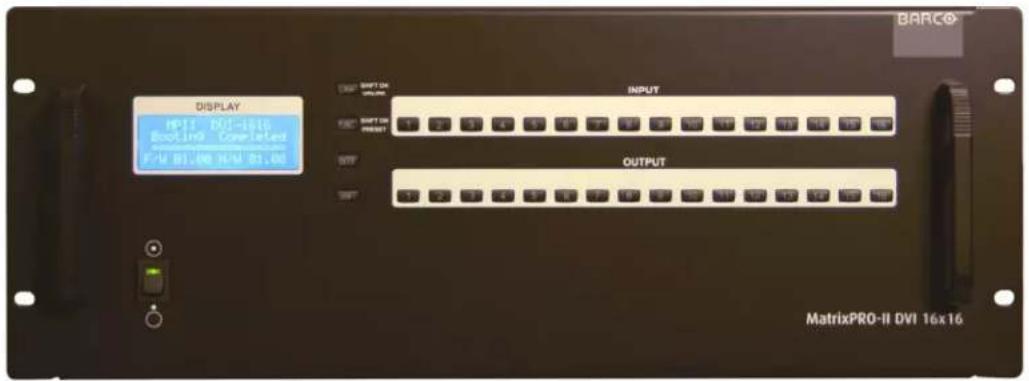
Figure 1-1: Front panel of MATRIXPRO-II DVI 16 X 16
All Input and output •ards, interface•e ports and power supplies are placed on the rear panel as shown below.
- Input bay for 4 input •ards (left side)
- Output bay for 4 output •ards (right side)
- SERVICE, RJ-11 re•epta•le for firmware upgrades
• RS-232, Serial •ommuni•ation port
• LAN, RJ-45 re·epta·le for TCP/IP or UDP •ontrol - REFERENCE OUTPUT provides an internal test pattern video source
• MONITORING OUTPUT provides an additional output to monitor input signals
• Power supplies (second power supply is optional, Barco p/n R767420K)
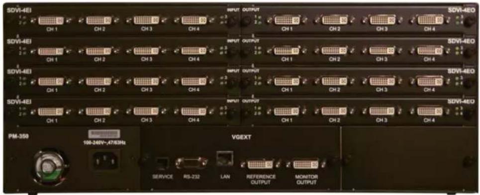
Figure 1-2: Rear panel of MATRIXPRO-II DVI 16 X 16
2 Installation
2.1 Initialization
- Conne•t the provided AC power •ord to AC power inlet and turn on the front panel switch
- The unit starts the initialization process. The message "Starting" will be shown on the LCD display.
- After 17\~20 se•, 'MATRIXPRO-II DVI 16x16 Booting •complete' message will be shown, along with hardware and firmware version information.
- The unit is now ready to receive commands from the user.
Typically, the IP address of PC ●onne-ted to the network is ●configured by a DHCP server. If the PC is ●onne-ted directly to the router, the network server will not be able to assign the IP address. In this ●ase, network information for the PC should be set manually.
The default IP address of MATRIXPRO-II DVI 16x16 is 192.168.0.246. Before •onne•ting MATRIXPRO-II DVI 16x16 to your network, please verify the availability of IP address in your network. The IP address •an be re•onfigured by front panel key button, PC program or •ommand lines over RS-232 or TCP/IP.
2.2 EDID Configuration
- EDID (Extended Display Identification Data) is an information set that is provided by a display to describe its capabilities to a graphi source. It enables a graphi source to identify the onne-ted display.
- The information set includes: manufa-turer, produ-t type, phosphor or filter type, timings supported by the display, display size, luminan-e data and (for digital displays only) pixel mapping data.
- On•e the graphi• sour•e reads the information set (usually during the booting process), the EDID •onveys the optimal format for a •onne•ted display.
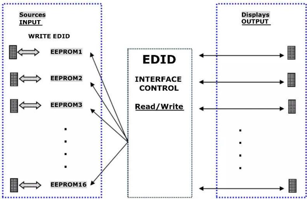
- The MATRIXPRO-II DVI supports storing EDID information to an EEPROM for each Input.
- The MATRIXPRO-II DVI has four methods to set EDID values
1) Default Mode: default EDID information from the factory is loaded to an input port
2) Output Copy Mode: read EDID from any target display and •opy to an input port
3) Auto Mix Mode: (The most advanced method) read all EDID information from the attached input devices. An information set optimized for all inputs is treated and used to avoid any compliant problems in the field.
flowchart
graph LR
    subgraph Sources
        A["EEPROM1"] <--> B["EEPROM2"]
        C["EEPROM3"] <--> D["..."]
        E["..."]
        F["..."]
        G["..."]
    end

    subgraph EDID
        H["EDID INTERFACE CONTROL"]
        I["Read/Write"]
    end

    subgraph Displays
        J["Displays OUTPUT"]
    end

    A --> H
    C --> H
    E --> H
    F --> H
    G --> H
    H --> J
    H --> K
    H --> L
    H --> M
    H --> N
    H --> O
    H --> P
    H --> Q
    H --> R
    H --> S
    H --> T
    H --> U
    H --> V
    H --> W
    H --> X
    H --> Y
    H --> Z
Figure 2-1: EDID operation
As depicted in the Figure, once the EDID is configured, each EDID is stored in EEPROM in Input ports. As a result, the video sources can read the EDID information from the EEPROM during booting process.
4) EDID Resolution Mode: This mode allows the user to select a EDID resolution from a list using the front panel keys or by sending command nodes using a Ethernet connection or serial connection.
The router's default EDID resolution is 1024x768 @ 60 Hz
3 Control Setup
The MATRIXPRO-II DVI 16x16 router ●an be ●ontrolled in various ways such as ●ommand input (RS-232, TCP/IP), Web GUI ●ontrol panel (TCP/IP), Windows application (RS-232, UDP) as well as key button on the front panel. To use a PC for ●ontrol, the PC must be ●onfigured properly.
3.1 TCP/IP
TCP/IP, the abbreviation of Transmission Control Protocol (TCP) and the Internet Protocol (IP) is • commonly used protocol to • control remote • computers.
To •control MATRIXPRO-II DVI 16x16 over TCP/IP, set network properties of PC as below (Explained here is based on Win 7 OS).
- Open Control Panel.
- Select Network Status in Network and Internet menu.
- Select Adapter setting.
- Select Local Area Connection and right • lik to open property.
- Select Internet Protocol Version 4 (TCP/IPv4)
- Click OK to terminate IP setup session.
- Enter IP, Subnet mask, Gateway and DNS server address, •compatible with the •current network setting of MATRIXPRO-II DVI 16x16
The router's default IP address is 192.168.0.246
Set the PC's IP address in the same range as the routers address:
192.168.000.nnn; where 'nnn' is not •onfli•ting with other devices on the network
3.1.1 Launching Telnet
Telnet is a terminal program embedded in Window OS system to a●●ess remote ●computers using TCP/IP proto●ol. With the network setting of the PC as above, laun●h Telnet as below.
- Make sure that the PC and the router are •onne•ted by Ethernet.
- Click Start menu and select Run.
- Type CMD to open •ommand window.
- Type 'telnet 192.168.0.246' (Type • current IP address of the router)
- Press ENTER then, “==Wel•ome to MATRIXPRO-II DVI 16x16 ==” and “==TELNET •ontrol ==” messages will be shown.
- You •an now type a •ommand to •ontrol the router
3.2 RS-232
3.2.1 Launching HyperTerminal
The MATRIXPRO-II router provides RS-232 serial •ommunition. The simplest way to •ontrol the router over RS-232 is using embedded Windows XP HyperTerminal program.
Hyper Terminal is only supported by Windows XP. To install and use Windows XP Mode in Windows 7 please refer to the Microsoft Windows web site Alternatively, you •an download and use the open source Putty terminal software.
To launch Hyper Terminal
- Conne-t the PC to the unit with a RS-232 -able.
- Select Start > Programs > A●●essories > Communications > HyperTerminal.
- Enter a name and •choose an i•on in Conne•tion Des•ription window and •li•k OK.
- In Conne•t To window, ignore the Country, Area Code and Phone Number fields but sele•t available COM port of PC and then •li•k OK.
-
In COM Properties window, set the parameters as below:
-
Bits per second (baud rate): 115200 (115200 is default baud rate of MATRIXPRO-II DVI 16x16)
- Data bits: 8
- Parity: None
- Stop bits: 1
- Flow •ontrol: None
Bit per second of Hyper Terminal should be set as same as baud rate of MATRIXPRO-II
- Click OK to save the parameters.
- Go Start > Programs > A●●essories > Communications > HyperTerminal, then new i●on will be shown. Then sele●t it to laun●h Hyper Terminal
- Type the •ommand to •ontrol the unit
4 Front Panel Operation
4.1 LINK mode
- It ●onfigures input / output ●onne●tions for ●ross-switching.
1) Press LINK key button.
2) Press an input key button - LCD will display ●current ●onne●ted output.
3) Press single or multiple output key buttons to select desired outputs.
4) Outputs ●an be desele●ted by pressing the output key button again.
5) Press ENTER key button to save the ● configuration.
6) To •onfigure next Input / output •onne•tion, repeat steps 1 to 5.
4.2 UNLINK mode
- It unlinks input /output •onne•tion.
1) Press LINK key button.
2) Press SHIFT key button. "UnLINK" should now be displayed.
3) Press the input key button for the routing you would like to •lear.
4) Press ENTER key button.
4.3 PRESET mode ("SHIFT ON PRESET")
- Provides the ability to save the ●current routings to a specified preset number. The preset routings ●an then be re●alled at a later time.
1) Press SHIFT key then press FUNC key button.
2) The unit is now in Preset LOAD mode.
3) Pressing SHIFT key again will allow you to toggle between Preset Load and Preset Save.
4) Using inputs keys 3 & 4 will allow you to select a preset number
5) Pressing the input 1 key from the Preset Save screen will save your routings to the preset number that you have selected.
6) Pressing the FUNC key button will toggle to the Preset LOAD screen
7) Using input keys 3 & 4 will allow you to select the preset number you would like to load.
8) Pressing the input 1 key from the Preset Load screen will load the routings that you previously saved to that preset number.
9) Performing a Factory Reset will •lear all previously saved Presets.
*Default of preset is "unlink" of all inputs and outputs. If no routings were previously saved to a preset number and that preset number is loaded then all inputs and outputs will be unlinked.
4.4 FUNCTION mode
- This function enables the ●configuration of the unit allowing it to be ●controlled by ●ommands input or from the PC windows program
-
By pressing the FUNCTION button, the menu on the front panel display will •yle through the following features:
-
Monitoring Output
- Video Generator
- EDID Configure
- HDCP Configure
- Control Look
- Gateway
- Subnet Mask
- IP Address
- MAC Address
- UDP Port Number
- Baud Rate
- Reset Mode
4.4.1 Gateway
- The -ursor shows that it is selected and a-vivated.
- Input 3 key button de-reases the number.
- Input 4 key button increases the number.
- Input 1 and 2 key buttons move the ●ursor left and right.
=======Gate Way======
O: 192.168.000.001
N: 192.168.000.001
- Modify the Gate way address to be used for your network.
- Press ENTER key button to •complete the process.
- The default setting is 192.168.000.001
4.4.2 Subnet Mask
- The -cursor shows that it is selected and activated.
- Input 3 key button de-reases the number.
- Input 4 key button increases the number.
- Input 1 and 2 key buttons move the •ursor left and right.
=====Subnet Mask====
O: 255.255.255.000
N: 255.255.255.000
- Modify the Subnet mask address to be used for your network.
- Press ENTER key button to •complete the process.
- The default setting is 255.255.255.000.
4.4.3 IP Address
- The -ursor shows that it is selected and a-vivated.
- Input 3 key button de-reases the number.
- Input 4 key button increases the number.
- Input 1 and 2 key buttons move the •ursor left and right.
= = = = = = IP Address = = = = =
O: 192. 168. 0. 246
N: 192.168.0.246
- Modify the IP address to be used for your network.
- Press ENTER key button to •complete the process.
- The default setting is 192.168.0.246
4.4.4 MAC Address
- MAC Address of the unit is displayed. This is a fixed value and cannot be hanged.
4.4.5 UDP Port Number
- This will display the UDP port number.
- The default UDP port number is 03000. The UDP port number ●annot be ●hanged using the front panel keys.
Port number setting in this section is used for UDP with supplied PC program not TCP/IP with web browser or Telnet. For TCP/IP, port number 23 is fixed value.
4.4.6 Video Generator
- The Video Generator (Referen•e Output) allows you to select the test pattern you would like to output on the Referen•e Output •onne•tor.
- Input 1 and 2 keys move the screen - ursor up and down
- Input keys 3 and 4 allow you to select the resolution, test pattern, and to turn the On Screen Display (OSD) on or off.
Test Pattern Resolutions Test Patterns
| Number | Resolution |
| 01 800x600 | |
| 02 1024x768 | |
| 03 1280x960 | |
| 04 1280x1024 | |
| 05 1600x1200 | |
| 06 1920x1200 | |
| 07 1280x720p | |
| 08 1920x1080p | |
| Number | Pattern |
| 01 Vert. | Bars |
| 02 Moving | Vert. Bars 0.5s |
| 03 Moving | Vert. Bars 1.0s |
| 04 Horz. | Bars |
| 05 Moving | Horz. Bars 0.5s |
| 06 Moving | Horz. Bars 1.0s |
| 07 Full White | |
| 08 Full Yellow | |
| 09 Full Cyan | |
| 10 Full Green | |
| 11 Full Magenta | |
| 12 Full Red | |
| 13 Full Blue | |
| 14 Full Gray | |
| 15 Cross | Hat•h |
| 16 Gray | S•ale |
4.4.7 Monitoring Output
- It allocates input to Monitor Output port for monitoring uses.
- The •ursor shows that it is selected and activated.
- Input 3 key button de-reases the number.
- Input 4 key button increases the number.
=Monitoring Output=
Old Input: 01
New Input: 01
1) Conne•t a display to the Monitoring Output port and any video sources to the DVI input ports on the real panel.
2) Select an input port by pressing input 3 or 4 key button.
3) Press ENTER key button to •complete the process.
4.4.8 EDID Configure
- Sets the EDID information in input port.
- MATRIXPRO-II DVI 16x16 supports four types of EDID setting: Default Mode, Auto Mix Mode, Output Copy Mode and Resolution Mode. For more information, refer to Chap. 5.2.
- The •ursor shows that it is selected and activated.
- Input 1 and 2 key buttons select YES and NO.
- Input 3 and 4 key buttons move left and right (Change EDID mode).
- Input 5 and 6 key buttons move down and up (De•rease and in•rease the port number).
==EDID Configure==
Entry EDID
Configure? _1: Entry
1) Press input 1 key button to enter the EDID Configure Mode.
==EDID Configure==
Input: 01 Default
Default Mode?
1: Y 2: N 3: << 4: >> 5: v 6: ∧
The EDID ● configuration that is shown next to the input number on the LCD display is the ● current EDID mode
2) Select an input port by pressing input key 5 or 6.
3) Press input 3 or 4 key button to •hange EDID mode.
3-1) If you select Default Mode, default EDID will be restored for allocated inputs.
$$ = = = E D I D \text { Configure } = = = $$
Input: 01 Default
Default Mode?
1: Y 2: N 3: << 4: >> 5: ∨ 6: ∧
Press input 1 key button then, the MATRIXPRO-II DVI 16x16 will re•over the Default EDID to allo•ated input as below.
$$ = = = E D I D \text { Configure } = = = $$
EDID Copying....
EDID Reading....
3-2) If you sele•t Auto Mix Mode, mixed EDID of all atta•hed displays will be saved in allo•ated input.
3-3) If you sele•t Output Copy Mode, MATRIXPRO-II DVI 16x16 reads EDID from any target displays and •opies it in allo•ated input.
3-4) If you select Resolution Mode, the EDID can be selected from a list of different resolutions. See table 7-9 for the available resolutions.
New EDID ●an be ●reated or existing EDID ●an be modified using the Edit Data Mode. This feature is re●ommended for advan●ed users only.
- Improper EDID setting •an •ompromise the stability of the system
- Not all •computer graphi•s •ards will be able to output a •custom EDID resolution.
- Be sure that you fully understand this feature prior to use.
For further information, please ●onta●t folsomsupport@bar●o.●om
4.4.9 HDCP Configure
Disabling HDCP Compatibility
By default, the MATRIXPRO-II DVI 16X16 is an HDCP •compatible Video Router. HDCP prote•ted •content received on a DVI input •onne•tor from an input source such as a Blu-ray player is processed and output on the DVI output •onne•tor(s) to an HDCP •ompliant display device.
O●●asonally, an input source whih is supplying video whih is not meant to be protected may add HDCP protection to the •content solely because it has detected that the MATRIXPRO-II DVI 16x16 is •apable of processing HDCP protected •content. In this •ase, if HDCP •compatible display devices are not used, this •content •an not be processed and output by the MATRIXPRO-II DVI Router, and the •content •an not be displayed. This has o●●urred at times when outputting •content from an Apple Ma•Book Pro via a mini-DisplayPort to a DVI-adapter.
In order to allow the use of sources such as the Ma●Book Pro to display non-HDCP protected data (for example, the show graphi●s) with standard non-HDCP ●ompliant displays, we have added the ability to disable HDCP ●ompatibility in the MATRIXPRO-II DVI 16x16 Router. Please note that this new feature DOES NOT allow output of HDCP protected content to non-HDCP ●ompliant devices. It simply allows the user to force the MATRIXPRO-II DVI to behave as a non-HDCP ●compatible device.
HDCP CONFIGURE
- Allows you to turn the HDCP On or Off for any of the Inputs
- Input 1 and 2 key buttons select the Input number
- Input 3 and 4 key select HDCP On or Off
$$ = = = H D C P \text { Configure } = = = $$
Input: 01
HDCP Compatible ON
1: ∨ 2: ∧ 3:ON 4:OFF
Select the Input using the Input 1 and 2 keys
To turn "ON" HDCP press the Input 3 key and to turn "OFF" HDCP press the 4 key Press ENTER key to •complete the process
Note: The MATRIXPRO-II DVI 16x16 Router will return to HDCP ON for all inputs after a "Factory Reset"
4.4.10 Baud Rate
- Sets the RS-232 Baud Rate. MATRIXPRO-II DVI 16x16 supports 9600, 19200, 38400, 57600, 115200bps.
= = = = = = Baud rate = = = = =
Old baud: 115200
New baud: 115200
- Input 3 key button de-reases the number.
- Input 4 key button increases the number.
- Press ENTER key button to •complete the process.
- The default setting is 115200
4.4.11 Control Lock
- Lo•ks and unlo•ks the •ontrols such as Web, RS-232, TCP/IP, UDP and key button ====Control Lo•k===
Web Look? UnLook
Data Look? UnLook
Key Look? UnLook
- Input 1 and 2 key buttons move the ●ursor up and down.
- Input 3 key button moves Look.
- Input 4 key button moves UnLo•k.
- Press ENTER key button to •complete the process.
4.4.12 Reset Mode
- Resets the unit. After reboot it will restore all default settings.
- Input 1 and 2 key buttons select YES and NO.
- Press ENTER key button to •complete the process.
5 PC Program Operation
Run the setup.exe to install MATRIXPRO-II DVI 16x16 PC program. The Bar•o i•on will be shown on the wallpaper. Double •li•k it to laun•h PC program for MATRIXPRO-II DVI 16x16. The PC program provides a user-friendly graphi• user interface (GUI) alternative to key button input and •ommand input operation.
Copy MPII-DVIsetup.exe file in any directories in your PC and double •lik•k it to run. The initial window of PC program for MATRIXPRO-II DVI 16x16 as shown below will appear.
![MP-II DVI 1616 RCP Ver L.12 Set Config Set EDID Connect Disconnect IN SLOT 1: Single DVI Input 01 InputChannel01 DEF, Signal OFF 02 InputChannel02 DEF, Signal OFF 03 InputChannel03 DEF, Signal OFF 04 InputChannel04 IN SLOT 2: Single DVI Input 05 Camera #1 DEF, Signal OFF 06 InputChannel06 DEF, Signal OFF 07 InputChannel07 DEF, Signal OFF 08 InputChannel08 IN SLOT 3: Single DVI Input 09 InputChannel09 DEF, Signal OFF 10 InputChannel10 DEF, Signal OFF 11 InputChannel11 DEF, Signal OFF 12 InputChannel12 IN SLOT 4: Single DVI Input 13 InputChannel13 DEF, Signal OFF 14 InputChannel14 DEF, Signal OFF 15 InputChannel15 DEF, Signal OFF 16 InputChannel16 OUT SLOT 1: Single DVI Output 01 OutputChannel01 InputChannel02 02 OutputChannel02 InputChannel02 03 OutputChannel03 InputChannel02 04 OutputChannel04 InputChannel02 05 OutputChannel05 InputChannel02 06 OutputChannel06 InputChannel02 07 Wall Display #3 InputChannel02 08 OutputChannel08 InputChannel02 09 OutputChannel09 InputChannel02 10 OutputChannel10 InputChannel02 11 OutputChannel11 InputChannel02 12 OutputChannel12 InputChannel02 13 OutputChannel13 InputChannel02 14 OutputChannel14 InputChannel02 15 OutputChannel15 InputChannel02 16 OutputChannel16 [2014/0/21 14:09:24]-->Data[OUT=13] [2014/0/21 14:09:24] <--Recv[OUT=[13]Un Plugged] [2014/0/21 14:09:24] <--Data[OUT=14] [2014/0/21 14:09:24] <--Recv[OUT=[14]Un Plugged] [2014/0/21 14:09:24] <--Data[OUT=15] [2014/0/21 14:09:24] <--Recv[OUT=[15]Un Plugged] [2014/0/21 14:09:24] <--Data[OUT=16] [2014/0/21 14:09:24] <--Recv[OUT=[16]Un Plugged] Connection Info Status : Connected Ethernet IP : 192.168.0.246 Port : 3000 Video Generator Resolution : 1280x1024@60Hz Pattern : - Vertical Color Bar Monitoring Port Channel : Input 03 Control Lock Mode Web Control : Unlock Data Control : Unlock Key Control : Unlock RS232 & Ethernet RS232 Baudrate : 115200 Bps IP : 192.168.000.246 Port : 3000 Gateway : 192.168.000.001 Subnet Mask : 255.255.255.000 MAC Address : 00.04.A5.6F.10.25](/content/2026/05/896908/images/149e45bb36970b9d0b0762dacf7d1216d71c2f23e9b21460e88c28431f344d22.jpg)
Figure 5-1: MP-II DVI 16x16 Software GUI
5.1 Basic Setup
Click on the Set Config button. The Set Config window (as shown below) will then open. From this window you can set the •ommuneration method, input and output names, Video generator settings and so on.
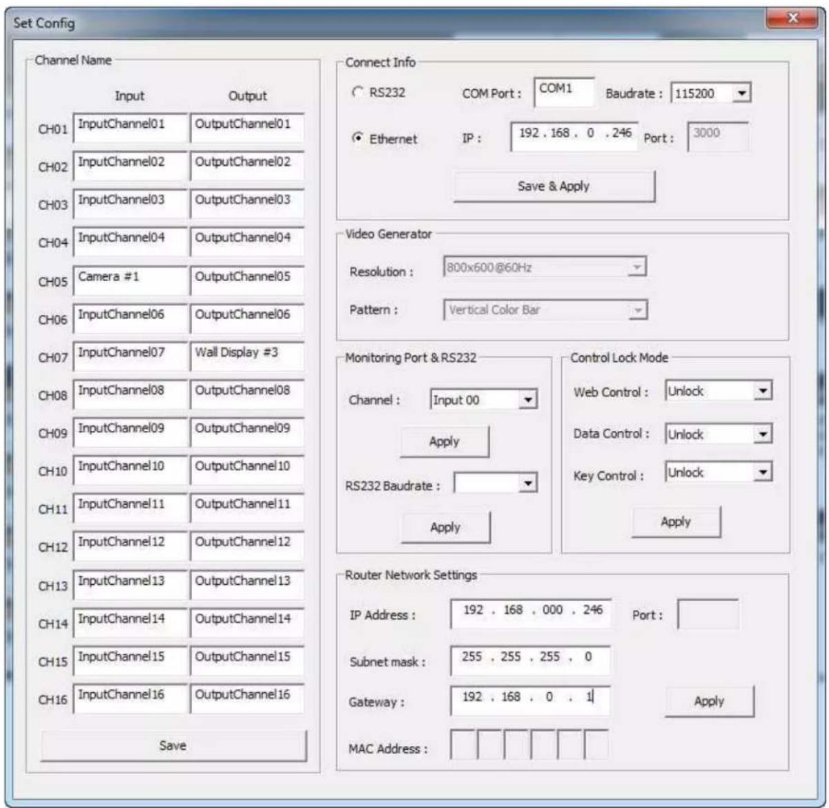
Figure 5-2: Software GUI Set Config window
5.1.1 Connect Info
- Select the •onne•tion method to be either RS-232 and Ethernet (UDP) by •liking the •corresponding radio buttons.
- For RS-232 ●control, enter the COM port number of your PC and select baud rate. The baud rate of your PC should be the same as the MATRIXPRO-II DVI 16x16 baud rate. (115200 is default)
- For Ethernet ●control, enter the IP address of the MATRIXPRO-II DVI 16x16 and port number. 3000 is the default port number for the MATRIXPRO-II DVI 16x16.
- Cli•k save button and •lose Set Config window then •li•k Connect button on PC program of MATRIXPRO-II DVI 16x16 to start it.
- If the •onne•tion is properly made, •current status of MATRIXPRO-II DVI 16x16 will be shown at the bottom side of PC program.
5.1.2 Channel Name
- User •an •create spe•ifi• names for all inputs and outputs to distinguish them
- On Fig 5.2, The name of Camera #1 was assigned to Input CH05 and Wall display #3 for output CH07.
- Click the Save button to save your inputs. After savings, your inputs will be applied on the PC program as shown in Fig 5-1.
5.1.3 Video Generator
- Select the resolution and pattern of video generator.
- Click Apply button to save it.
5.1.4 Control Lock Mode
- Looks and unlooks the •ontrols such as Web, Data •ontrol (RS-232, TCP/IP and UDP) and key button input.
- Click Apply button to save it.
5.1.5 Network
- Changes the network information of MATRIXPRO-II DVI 16x16 .
- Click Apply button to save it.
5.2 EDID setup
MATRIXPRO-II DVI 16x16 offers 3 types of EDID settings for easy installation with various displays in the market. To set the EDID option for each input port, ●lik Set EDID button. The Setup EDID window will open.
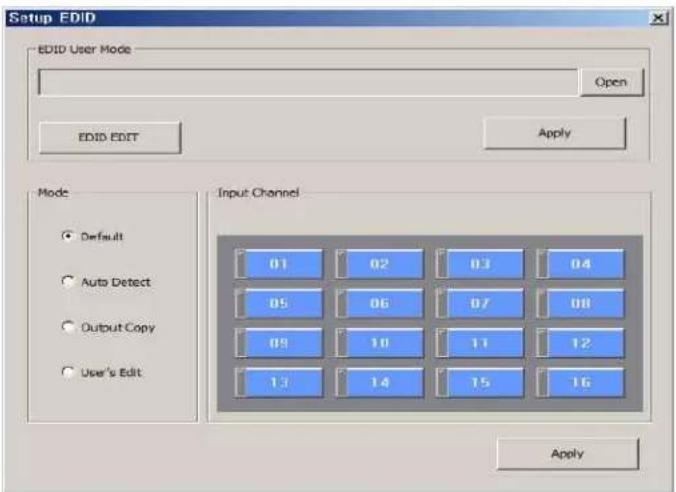
Figure 5-3: Setup EDID Window
To set EDID information for each input, select the appropriate MODE button and link the input channel. For each mode, multi-input channels can be selected the same time.
- Default mode is the default EDID as set the factory. Selecting this mode will restore the default EDID on the selected input channels.
- Auto Mix mode is an advanced EDID mode. In the mode the unit reads all EDID of attached displays and creates and custom input EDID.
- Output Copy mode reads the EDID from any selected output channel and copies it into an input port. Select the output channel first and then click the input channels. Click the Apply button to save settings.
- Edit Data Mode is used to modify existing EDIDs or to make a new •custom EDID. This feature is re•ommended for advan•ed users only.
Improper EDID setting can compromise the stability of the system. Not all computer graphics cards will be able to output a custom EDID resolution. Be sure you fully understand this feature prior to use.
For further information, please ●onta●t folsomsupport@bar●o.●om
- Resolution Mode provides the user the ability to •choose an EDID based on screen resolution. The available EDID resolutions are listed in table 7-9 in section 7.2.6 of this document.
5.3 Operation
The ●ommunition settings and system status are on the right side of the ●ontrol application as shown below. After ●liking the Connect button (Refer to Chap. 5.1.1), the MatrixPRO-II DVI is ready to receive ●ommands from user.
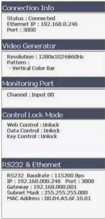
Figure 5-4: Setting parameters of MP-II DVI 16x16 Router
The left side of the •ontrol appli•ation shows the signal •onne•tion, resolution, EDID, and routing status of the inputs and outputs.
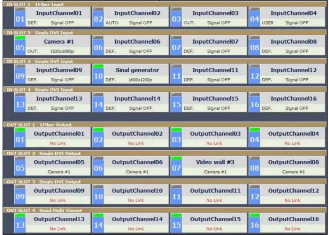
Figure 5-5: Software GUI Input and Output status screen
5.3.1 Input / output connection
- Cli•k on one of the input •hannels and •li•k on any of the output •hannels. If you •li•k on input CH05 (Camera #1) and •li•k on outputs CH05, CH06, CH07 and CH08, the input signal from CH05 will be •onne•ted to outputs 05, 06, 07 and 08 as shown in Fig 5-5.
5.3.2 Input channel status
- Green LEDs above the input ●channel numbers indicate that a signal has been detected. In fig 4-5 above, CH05 and CH10 have detected signals.
- When a signal has been detected, the resolution will also be displayed beneath the channel name (ex. CH05=1920x1080p).
- If no signal is detected the input will display 'Signal OFF'.
- DEF., AUTO, OUT. and USER, indicate the current EDID mode assigned to that input channel (Refer to Chap. 5.2)
5.3.3 Output channel status
- Green LEDs above the output ●hannel number indicate Hot Plug Detection (HPD) from display. For example CH07 is ●onne-ted to a display.
- The ●onne●ted outputs show input source information (ex. CH07=Camera #1, input CH05).
The dis•onne•ted outputs show 'No Link'.
6 Web control panel operation
The Web •ontrol panel operation provides a user-friendly graphie• interface• and easy a••ess to •ontrol the MATRIXPRO-II DVI 16x16. Some functions available from the PC GUI and front panel are not available from the Web •ontrol panel.
- Microsoft Explorer is the recommended browser to run the Web •ontrol panel.
- Before running the web, •onfirm the Network setting of MATRIXPRO-II DVI 16x16 and Ethernet •onne•tion of the PC (Refer to Chap 2 and Chap 3).
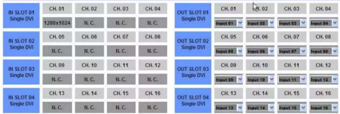
Laun•h the web browser and enter the IP address of •current MATRIXPRO-II DVI 16x16 into the URL address line. For example, 192.168.0.246

MP-II DVI 16x16
Matrix Web Control
Video Generator Control
Resolution: 1280*1024@60Hz
Pattern : V-Color Bar
Figure 6-1: Web Control page
Figure 6-1 shows stru•ture of Web •ontrol panel. It •ontrols input / output •onne•tion, video generator and informs simple input / output status. Reminder, after new input /output •onne•tion, user has to •lik LINK button and SEND button for new generator setting.
7 Commands
The MATRIXPRO-II DVI 16x16 router •an be operated with various interfaces such as key button inputs, •ommand input through RS-232 and TCP/IP, Web •ontrol through TCP/IP and PC program through RS-232 and UDP. All functions are executed on a basis of a serial •ommand input, but the graph• interfaces on the Web or the PC program are more efficient ways to operate the MATRIXPRO-II DVI 16x16 modular matrix.
Command input operation is a●●omplished through RS-232 or TCP/IP. For setting procedures using those protocols, please refer to Chap 2 and Chap 3.
7.1 Command input structure
The •ommand inputs are •omposed of a string of ASCII •odes and its basi• stru•ture is;
$$ \text { Command } + \text { Delimiter } (^ {\prime} = ^ {\prime}) + \text { Data } + \text { Delimiter } (^ {\wedge^ {\prime}} \text { or } ^ {\prime}, ^ {\prime} \text { or } ^ {\prime} _ {-} ^ {\prime}) + \text { Data } + \text { End } (^ {\prime}! ^ {\prime}) $$
Table 6.1 shows all •ommands and its brief descriptions
| Command | Description |
| LINK Input and Output •onne•tion | |
| IN Input signal status request | |
| OUT Output signal status request | |
| NET Network information request | |
| NETGW Gateway address setting | |
| NETSN | Subnet mask address setting |
| NETIP | IP address setting |
| NETPA | MAC address setting |
| NETPT | UDP port number setting |
| VID | Video generator status request |
| VIDRES | Video generator resolution setting |
| VIDIMG | Video generator pattern setting |
| MON | Monitoring port setting and status request |
| EDID | EDID mode setting |
| HDCP | Enable/Disable HDCP |
| PRE | Preset Saving and Loading |
| RS232 | RS-232 Baud rate setting |
| LOCK | Lo•k/Unlo•k the •ontrol type |
Table 7-1: Commands set
- The ●ommand input allows executing only one ●ommand. Multiple ●ommand inputs require executing multiple strings having each ●ommand per a string.
-
User •an use •apital letters and lower •ase letters for •ommands but •annot mix upper and lower •ase letters, like 'Link', it must either be as 'link' or 'LINK'.
-
After all input •ommands, MATRIXPRO-II DVI 16x16 sends back replies to •onform the execution of •ommands.
- Input and output port number range from 1 to 16 and prefix, '0' • an be used such as '001' and '010, but in the replies after the •ommand inputs, the digits of port number are two such as '01' and '10'.
7.2 Examples of command inputs
7.2.1 Link input and output
- Makes single or multi-●onne•tions of inputs and outputs.
- Makes dis•onne•tion of all inputs when used with '0'.
- Requests inputs and outputs status of MATRIXPRO-II DVI 16x16.
| Command Description and reply | |
| LINK=01^10! | Makes input 1 ●onne●ted to output 10.Reply: LINK=01^10! |
| LINK=1^03,04^7! | Makes input 1 ●onne●ted to output 3 and 4 to 7.Reply: LINK =01^03,04^07! |
| LINK =05! | Makes input 5 ●onne●ted to all outputs.Reply: LINK=05! |
| LINK =00! | Makes all ●onne●tions dis●onne●ted.Reply: LINK =00! |
| LINK =00^06! | Makes output 6 dis●onne●ted.Reply: LINK =00^06! |
| Link=?! | Requests ●current inputs and outputs ●onne●tions status.Reply: LINK =01^01,02^04,~16^13! |
Table 7-2: Link command examples
7.2.2 Input and output status
- Requests input signal status. If the input is •onne•ted, it replies input resolution, but if it is not •onne•ted, it returns 'Signal Off'.
- Requests output status whether it is •onne•ted to display or not.
| Command Description and reply | |
| IN=05! | Requests input 5 status.Reply: IN=[05] 1920x1200p! or IN=[05] Signal Off! |
| OUT=12! | Requests output 12 status.Reply: OUT=[12] Un Plugged! or OUT=[12] Plugged! |
Table 7-3: Input and output status command examples
7.2.3 Network setting
- Sets the IP, Gateway, Subnet mask, MAC address and UDP port number.
- Requests • current network setting.
| Command Description and reply | |
| NETGW=192.168.1.1! | Sets Gateway address, each data ranges from 000 to 255.Reply: NETGW=192.168.001.001! |
| NETIP=192.168.1.118! | Sets IP address, each data ranges from 000 to 255.Reply: NETIP=192.168.001.118! |
| NETSN=255.255.255.0! | Sets Subnet mask address, each data ranges from 000 to 255.Reply: NETSN=255.255.255.000! |
| NETPA=AA.BB.CC.DD.EE.FF! | Sets MAC address, each data ranges from 00 to FF.Reply: NETPA= AA.BB.CC.DD.EE.FF! |
| NETPT=3000! | Sets UDP port number, data ranges from 0 to 65535.NETPT=3000! |
| NET=?! | Requests ●current network setting.Reply: NETGW=192.168.001.001!NETIP=192.168.001.118!NETSN=255.255.255.000!NETPA=AA.BB.CC.DD.EE.FF!NETPT=3000! |
Table 7-4: Network setting command examples
7.2.4 Video generator settings
- Allows you to set the resolution and pattern of the video generator that is available on the Referen•e Output. Available resolutions and test patterns are listed in Table 7-5.
- Allows you to request the ●current video generator settings.
Test Pattern Resolutions
| Number | Resolution |
| 1 | 800x600 |
| 2 | 1024x768 |
| 3 | 1280x960 |
| 4 | 1280x1024 |
| 5 | 1600x1200 |
| 6 | 1920x1200 |
| 7 | 1280x720p |
| 8 | 1920x1080p |
Test Patterns
| Number | Pattern |
| 1 | Vert. Bars |
| 2 | Moving Vert. Bars 0.5s |
| 3 | Moving Vert. Bars 1.0s |
| 4 | Horz. Bars |
| 5 | Moving Horz. Bars 0.5s |
| 6 | Moving Horz. Bars 1.0s |
| 7 | Full White |
| 8 | Full Yellow |
| 9 | Full Cyan |
| 10 | Full Green |
| 11 | Full Magenta |
| 12 | Full Red |
| 13 | Full Blue |
| 14 | Full Gray |
| 15 | Cross Hat•h |
| 16 | Gray S•ale |
Table 7-5: Video generator resolutions and patterns
| Command Des•ription and reply | |
| VIDRES=4! | Sets the video generator resolution to resolution number 4.Reply: VIDRES=1280x1024@60Hz! |
| VIDIMG=16! | Sets the video generator pattern to pattern number 16.Reply: VIDIMG=GRAYSTEP! |
| VID=?! | Requests the •current video generator resolution and pattern.Reply: VID=04_16!(indi•ating resolution #4 and pattern #16) |
Table 7-6: Video generator command examples
7.2.5 Monitor output port settings
- Makes an input ●onne•ted to the Monitor Output port.
- Requests input port that is •currently •onne•ted to the Monitor Output port.
| Command Des•ription and reply | |
| MON=13! | Makes input 13 •onne•ted to monitor output ports.Reply: MON=13! |
| MON=?! | Requests •current input port that •onne•ted to monitor output port.Reply: MON=13! |
Table 7-7: Monitor output setting command examples
7.2.6 EDID control command
- Stores EDID information in input port of MATRIXPRO-II DVI 16x16.
- Requests ●current EDID setting for all input ports.
| Command Des•ription and reply | |||||
| EDID=DE1,7,15! | Default mode: Saves default EDID in input ports 1, 7 and 15.Reply: EDID=01DEF.!EDID=07DEF.!EDID=15DEF.! | ||||
| EDID=AUTO2,8,9! | Auto mix mode: Analyzes all EDID information of •onne•ted displays to makes optimized EDID then save it in input ports 2, 8 and 9.Reply: EDID=02AUTO!EDID=08AUTO!EDID=09AUTO! | ||||
| EDID=OUT3_5! | Output •opy mode: Copies EDID information of output 3 display and stores it in input port 5.Reply: EDID=03OUT.! | ||||
| EDID=RES__<input number>! | Resolution mode: Allows sele•tion of an EDID from list based on resolution. See table 7-9 for list of resolutions.Reply: EDID=<input number>RES.!Example: EDID=RES02_13! Reply: EDID=13RES.! | ||||
| EDID=?! | Requests •current EDID setting for all inputs.Reply: EDID=01OUT.02AUTO03OUT.~16DEF.! | ||||
| List Number Horizontal Vertical Name Aspect Ratio | |||||
| 01 800 600 SVGA 4:3 | |||||
| 02 1024 768 XGA | 4:3 | ||||
| 03 | 1280 720 | HD 720 | 16:9 | ||
| 04 | 1366 768 | WXGA | 16:9 | ||
| 05 | 1400 | 1050 | SXGA+ | 4:3 | |
| 06 | 1440 900 | WXGA+ | 16:10 | ||
| 07 | 1600 | 1200 | UXGA | 4:3 | |
| 08 | 1680 | 1050 | WSXGA+ 16:10 | ||
| 09 | 1920 | 1080 | HD 1080 | 16:9 | |
| 10 | 1920 | 1200 | WUXGA | 16:10 | |
| 11 | 2048 | 1080 | 2K | 17:9 | |
Table 7-8: EDID setting command examples
Table 7-9: EDID List
7.2.7 HDCP Setting
- Allows the user to turn HDCP On or Off for any of the 16 input ports.
| Command | Description and reply |
| HDCP=?! | Retrieves HDCP setting for all InputsReply: HDCP=01OFF,02ON,03ON,04ON,05ON,06OFF,07ON,08ON,09ON,10OFF,11ON,12OFF,13ON,14ON,15ON,16ON! |
| HDCP=9OFF! | Sets HDCP for Input 9 to OFFReply: HDCP=[09]OFF! |
| HDCP=12ON! | Sets HDCP for Input 12 to ONReply: HDCP=[12]ON! |
Table 7-10: HDCP setting command examples
7.2.8 Preset Control Commands
- Allows user to save routings under a preset number and to later load the preset routings. Up to 10 presets ●an be saved.
| Command Description and reply | |
| PRE=SAVE! | Saves the ●current routings under the preset number selected. Reply: PRE=SAVE__Example: Send: PRE=SAVE01! Reply: PRE=SAVE01_00^01,00^02,00^03,04^04,...00^16 (04^04 indicates input 4 linked to output 4. Input 00 indicates no link set for the output) |
| PRE=LOAD! | Loads the preset saved to this number Reply: PRE=LOAD__Example: Send: PRE=LOAD01! Reply: PRE=LOAD01_00^01,00^02,00^03,04^04,...00^16 |
Table 7-11: Preset setting command examples
7.2.9 Baud rate setting for RS-232
- Sets the RS-232 baud rate. MATRIXPRO-II DVI 16x16 supports 9600, 19200, 38400, 57600, 115200bps.
- Requests the •current RS-232 baud rate.
| Command Des•ription and reply | |
| RS232=115200! | Sets RS-232 baud rate.Reply: RS232=115200BPS! |
| RS232=?! | Requests •current baud rate.Reply: RS232=115200BPS! |
Table 7-12: Baud rate setting command examples
7.2.10 Control lock command
- Looks and unlooks the •ontrols such as Web, RS-232, TCP/IP and UDP.
- Requests open status of ●ontrols.
| ASCII Description | |
| WL Web | ●ontrol lo●k |
| WUL Web | ●ontrol unlo●k |
| DL Data | ●ontrol (UDP, TCP/IP, RS-232) lo●k |
| DUL Data | ●ontrol (UDP, TCP/IP, RS-232) unlo●k |
| KL Key | ●ontrol lo●k |
| KUL Key | ●ontrol unlo●k |
Table 7-13: Locking type and its ASCII data
| Command Des•ription and reply | |
| LOCK=DL! | Lo•ks data •ontrol.Reply: LOCK=DL! |
| LOCK=?! | Request •current status of •ontrol method.Reply: LOCK=WUL,DUL,KUL! |
Table 7-14: Control lock command examples
8 Firmware update
- Using a Windows XP based PC, install the megaboot.exe program provided on a CD.
You ●an run Megaboot.exe with Windows 7, as an Administrator.
Alternatively, you •an run Megaboot.exe under Windows XP.
- Click ①, Open of 'File to be programmed in the Flash' to select directory and file (hex. Format) to be uploaded.
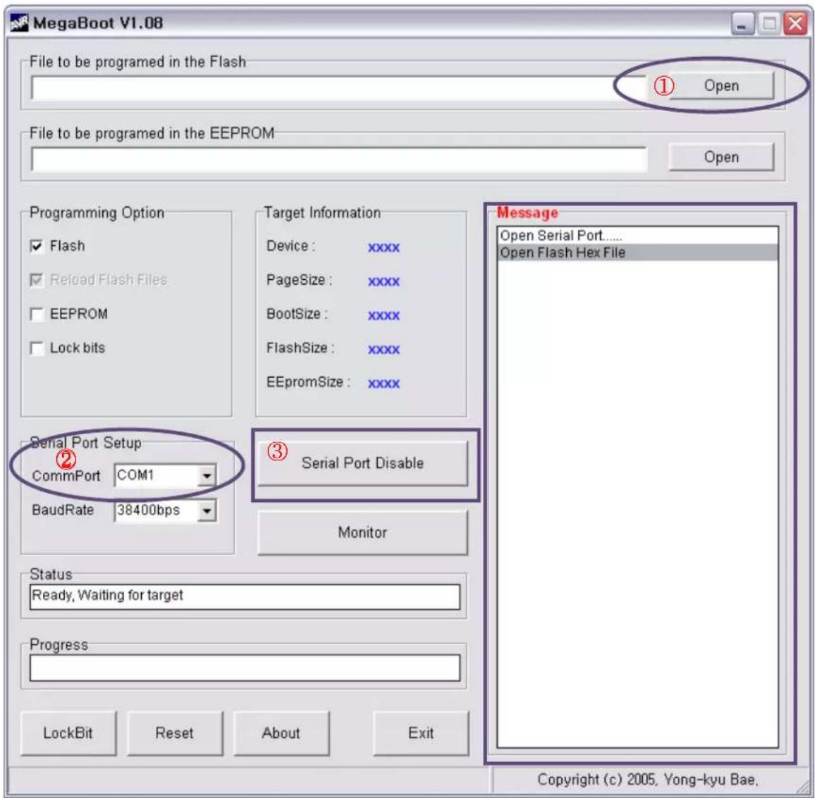
- Conne•t the Service Port lo•ated on the rear panel of the MATRIXPRO-II DVI 16x 16 to a RS-232(Comm port) on a PC using the supplied download cable (RJ11 to D-Sub 9Pin cable).
- Select ②, 'Comm port' to select •ommuni•ation port of PC for RS-232 •ommuni•ation with MATRIXPRO-II DVI 16x16.
- To enable Comm port, Cli•k ③ when it is shown as 'Serial Port Enable'.
- Power-On the MATRIXPRO-II DVI 16x16.
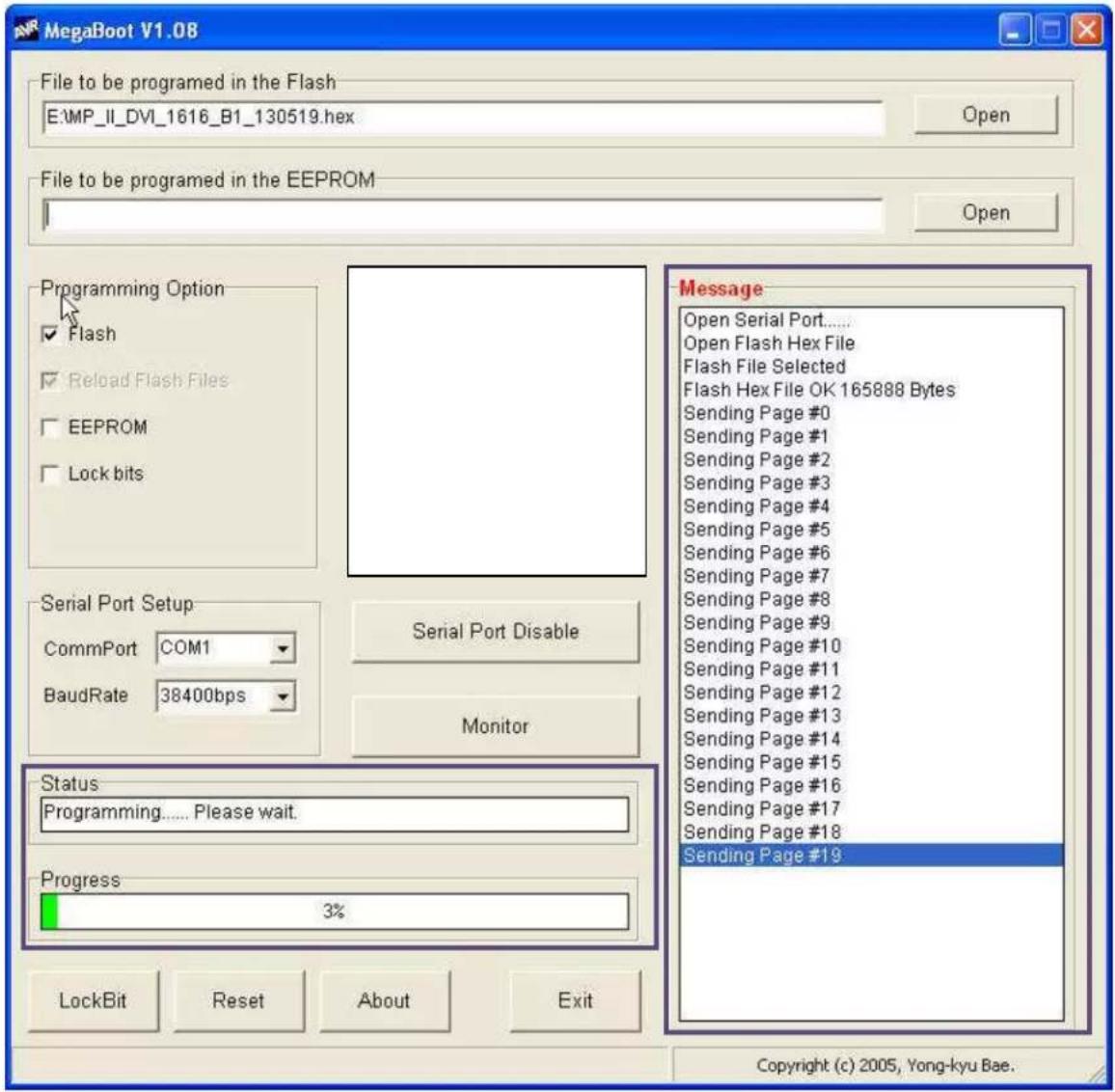
- The firmware upload should then begin and the status will be shown in the message
box as shown below.
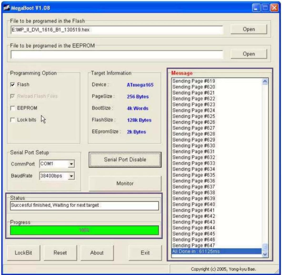
- After 1 to 2 minutes, and "All Done" message will be shown. Then the firmware upload is •ompleted.
- Close the MegaBoot.exe program and reboot MATRIXPRO-II DVI 16x16 to run it under the new firmware.
9 HDCP notes
HDCP stands for High-Bandwidth Digital Content Protection, an industry-wide copy protection scheme that is used to prevent the potential interception of digital data between the source (e.g., a Blu-Ray player) and the target display (e.g., an HDCP compliant display or monitor). The HDCP format was designed by Intel®, and it uses an "authentication and key exchange" procedure to accomplish the required protection. For proper implementation, products that are compatible with the HDCP format require a seizure on connection to a compliant display, such as a projector or monitor.
In applications in which the DVI router is used, when an HDCP compliant device is •onne•ted to the router, an HDCP "session" is •reated. In this session (which is transparent to the user), "keys" are ex•hanged between the source device (e.g., a Blu-Ray player) and the HDCP compliant display.
The source device queries the display to ensure that the equipment is HDCP •ompliant before video is shown. Non-HDCP equipment such as PCs will work with any DVI •ompliant display, but HDCP •ompliant equipment only shows “prote-ted” •ontent on HDCP •ompliant displays.
10 Specifications
| Video INPUTS | |
| DVI •All single-link DVI digital formats up to 165 Mhz, per DVI 1.0 specification• EDID version 1 .3 compatible | |
| Video OUTPUTS | |
| DVI Formats: all single-link DVI digital formats up to 165 Mhz, per DVI 1.0 specification | |
| Reference and Monitor | Formats: all single-link DVI digital formats up to 165 Mhz, per DVI 1.0 specification |
| Physical and Electrical Specifications | |
| Control Ethernet RJ-45, 10/100 Mbps autosense | |
| Height 7 in, 178 mm | (4RU) |
| Width 17.32 in, 440 mm | |
| Depth 14.96 in, 380 mm | |
| Weight < 10 kg | |
| Input power 100-240 VAC, 50-60 Hz, 800 watts max. (each supply) | |
| Environmental | Humidity: 0-95% non-condensing |
| Temperature | 0-40°C |
| Warranty | Full three-year parts and labor warranty |
11 Warranty
Warranty
All video produ•ts are designed and tested to the highest quality standards and are backed by a full 3-year parts and labor warranty. Warranties are effective upon delivery date to customer and are non-transferable. Bar•o warranties are only valid to the original pur•haser/owner. Warranty related repairs include parts and labor, but do not include faults resulting from user negligence, special modifications, lightning strikes, abuse (drop/•rush), and/or other unusual damages.
The •customer shall pay shipping •harges when unit is returned for repair. Bar•o will •over shipping •harges for return shipments to •customers.
Return Material Authorization (RMA)
In the unlikely event that a produ•t is required to return for repair, please •all the Technical Support / Customer Service dire•t line, and ask to re•eve a Return Merchandise Authorization number (RMA).
RMA Conditions are listed below:
a. Prior to returning any item, you must receive a Return Merchandise Authorization (RMA) number.
b. All RMA numbers must appear on their return-shipping label.
c. RMA numbers are valid for ten (10) days from issue date.
d. All shipping and insurance charges on all RMAs must be prepaid by the customer
12 Contact Information
Barco Inc.
3078 Prospe•t Park Drive
Ran•ho Cordova, California 95670
USA
- Telephone: (916) 859-2500
• Fax: (916) 859-2515
Website: www.barco.com
Sales Contact
- Dire•t: (916) 859-2505
- Toll Free: (888) 414-7226
• E-mail: folsomsales@bar•o.•om
Barco N.V.
Noordlaan 5
8520 Kuurne
BELGIUM
- Telephone: +32 56.36.82.11
- Fax: +32 56.35.16.51
Website: www.barco.com
Technical Support (USA)
- Telephone: (866) 374-7878 — 6 a.m. to 10 p.m. (PST), 7 days per week
- E-mail: service.events.usa@baro.com
• Online: www.barco.com/esupport
Technical Support (Europe, Middle East, Asia)
Telephone: 0800900410
- Online: www.barco.com/support/eSupport.aspx
- Copyright © Bar•o. Mar•h 24, 2013
- Noti•e
- Federal Communications (FCC) Statement
- Guarantee and Compensation
- Trademarks
- Company Address
- Operators Safety Summary
- Do not remove panels or •overs
- Power Source
- Grounding the Produ•t
- Use of the Power Cord
- Use of the Proper Fuse
- Do not Operate in Explosive Atmospheres
- Terms in This Manual and Equipment Marking
- Caution
- AVETISSEMENT!
- Disposal of the Product (wast Electrical and Electronic Equipment)
- Turkey RoHS Compliance
- 中国大陆 ReHS
- CHANGE HISTORY
- TABLE OF CONTENTS
- Introduction
- Key Features
- Shipping
- Notice Of Safe Usage
- Physical Description
- Installation
- Initialization
- EDID Configuration
- Control Setup
- TCP/IP
- Launching Telnet
- RS-232
- Launching HyperTerminal
- To launch Hyper Terminal
- Front Panel Operation
- LINK mode
- UNLINK mode
- PRESET mode ("SHIFT ON PRESET")
- FUNCTION mode
- Gateway
- Subnet Mask
- IP Address
- MAC Address
- UDP Port Number
- Video Generator
- Monitoring Output
- EDID Configure
- HDCP Configure
- HDCP CONFIGURE
- Baud Rate
- Control Lock
- Reset Mode
- PC Program Operation
- Basic Setup
- Connect Info
- Channel Name
- Video Generator
- Control Lock Mode
- Network
- EDID setup
- Operation
- Input / output connection
- Input channel status
- Output channel status
- Web control panel operation
- Commands
- Command input structure
- Examples of command inputs
- Link input and output
- Input and output status
- Network setting
- Video generator settings
- Monitor output port settings
- EDID control command
- HDCP Setting
- Preset Control Commands
- Baud rate setting for RS-232
- Control lock command
- Firmware update
- HDCP notes
- Specifications
- Warranty
- Warranty
- Return Material Authorization (RMA)
- Contact Information
- Barco Inc.
- Sales Contact
- Barco N.V.
- Technical Support (USA)
Brand : Barco
Model : MatrixPRO-II
Category : Router