
BT-BD 501 - Drill TAURUS - Free user manual and instructions
Find the device manual for free BT-BD 501 TAURUS in PDF.


| Product Type | Drill Press (Bench Drill) |
| Brand | Taurus |
| Model | BT-BD 501 |
| Power Input | 500 W, 230 V ~ 50 Hz |
| No-Load Speed | 280 – 2,350 rpm (9 speeds) |
| Chuck Capacity | 1.5 – 16 mm (scroll chuck) |
| Drill Depth | 50 mm |
| Reach (Throat) | 115 mm |
| Pillar Diameter | 46 mm |
| Overall Height | 650 mm |
| Weight | 21.5 kg |
| Sound Pressure Level | 61.5 dB(A) (K=3 dB) |
| Sound Power Level | 74.5 dB(A) (K=3 dB) |
| Motor Speed | 1,400 rpm |
| Load Factor | S2 15 min (intermittent duty) |
| Max Workpiece Size | 200 x 200 mm |
| Included Accessories | Scroll chuck, chuck key, folding chip guard, drill table, quick start guide, warranty card |
| Safety Features | No-volt trip switch, safety guard, earthing contact required |
| Material Compatibility | Metal, plastic, wood |
| Speed Selection | V-belt adjustment with 9 speed levels |
| Drill Table | Adjustable height and angle |
| Chip Guard | Folding transparent guard |
| Maintenance | Regrease bare parts, clean with damp cloth; no harsh solvents |
| Warranty | 1 year |
| Standards | EN 61029 |
Frequently Asked Questions - BT-BD 501 TAURUS
User questions about BT-BD 501 TAURUS
0 question about this device. Answer the ones you know or ask your own.
Ask a new question about this device
Download the instructions for your Drill in PDF format for free! Find your manual BT-BD 501 - TAURUS and take your electronic device back in hand. On this page are published all the documents necessary for the use of your device. BT-BD 501 by TAURUS.
USER MANUAL BT-BD 501 TAURUS
natural_image
Close-up of a black and white industrial drill press with a blue internal component and metal base (no visible text or symbols)INSTRUCTION MANUAL
MODEL NUMBER BT-BD 501
AFTER SALES SUPPORT
TEL: 1300 922 271
EMAIL: service.australia@einhell.com

N26704
Drill Press
What your 1 year warranty means
Great care has gone into the manufacture of this product and it should therefore provide you with years of good service when used properly. In the event of product failure within its intended use over the course of the first 1 year after the date of purchase, we will remedy the problem as quickly as possible once it has been brought to our attention. In the unlikely event of such an occurrence, or if you require any information about the product, please contact us via our after sales support services, details of which can be found in this manual and on the product itself.
Welcome Section
Congratulations on choosing to buy a TAURUS® product.
All products brought to you by TAURUS® are manufactured to the highest standards of performance and safety, and, as part of our philosophy of customer service and satisfaction, are backed by our comprehensive 1 Year Warranty.
We hope you will enjoy using your purchase for many years to come.
Table of Contents
| 1. General Safety Rules | Pg. | 5 | |||
| 2. | Special Saftey Rules | Pg. 6 | |||
| 3. | Layout | Pg. | 7 | ||
| 4. | Items | Supplied | Pg. | 7 | |
| 5. | Intended | Use | Pg. | 7 | |
| 6. | Technical | Data | Pg. | 8 | |
| 7. | Before starting the equipment | Pg. 8 | |||
| 8. | Operation | Pg. | 8 | ||
| 9. | Replacing the power cable | Pg. 10 | |||
| 10. | Cleaning, maintenance and ordering of spare parts | Pg. 10 | |||
| 11. | Storage | Pg. | 10 | ||
| 12. | Disposal and recycling | Pg. 10 | |||
bar
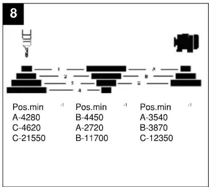
| Position | Value | |---|---| | Pos.min | -1 | | A-4280 | | | B-4450 | | | A-3540 | | | C-4620 | | | A-2720 | | | B-3870 | | | C-21550 | | | B-11700 | | | C-12350 | |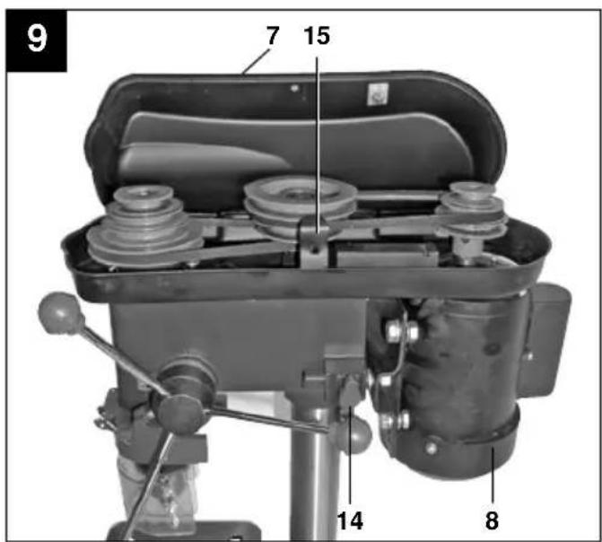
1. GENERAL SAFETY RULES
WARNING! Read all instructions Failure to follow all instructions listed below may result in electric shock, fire and/or serious injury. The term "power tool" in all of the warnings listed below refers to your mains-operated (corded) power tool or battery-operated (cordless) power tool.
SAVE THESE INSTRUCTIONS
1. Work area
a. Keep work area clean and well lit. Cluttered and dark areas invite accidents.
b. Do not operate power tools in explosive atmospheres, such as in the presence of flammable liquids, gases or dust. Power tools create sparks which may ignite the dust or fumes.
c. Keep children and bystanders away while operating a power tool. Distractions can cause you to lose control.
2. Electrical safety
a. Power tools plugs must match the outlet. Never modify the plug in any way. Do not use any adapter plugs with earthed (grounded) power tool. Unmodified plugs and matching outlets will reduce risk of electric shock.
b. Avoid body contact with earthed or grounded surfaces such as pipes, radiators, ranges and refrigerators. There is an increased risk of electric shock if your body is earthed or grounded.
c. Do not expose power tools to rain or wet conditions. Water entering a power tool will increase the risk of electric shock.
d. Do not abuse the cord. Never use the cord for carrying, pulling or unplugging the power tool. Keep cord away from heat, oil, sharp edges or moving parts. Damaged or entangled cords increase the risk of electric shock.
e. When operating a power tool outdoors, use an extension cord suitable for outdoor use. Use of a cord suitable for outdoor use reduces the risk of electric shock.
3. Personal safety
a. Stay alert, watch what you are doing and use common sense when operating a power tool. Do not use a power tool while you are tired or under the influence of drugs, alcohol or medication. A moment of inattention while operating power tools may result in serious personal injury.
b. Use safety equipment. Always wear eye protection. Safety equipment such as dust mask, non-skid safety shoes, hard hat, or hearing protection used for appropriate conditions will reduce personal injuries.
c. Avoid accidental starting. Ensure the switch is in the off-position before plugging in. Carrying power tools with your finger on the switch or plugging in power tools that have the switch on invites accidents.
d. Remove any adjusting key or wrench before
turning the power tool on. A wrench or a key left attached to rotating part of the power tool may result in personal injury.
e. Do not overreach. Keep proper footing and balance at all times. This enables better control of the power tool in unexpected situations.
f. Dress properly. Do not wear loose clothing or jewellery. Keep your hair, clothing and gloves away from moving parts. Loose clothes, jewellery or long hair can be caught in moving parts.
g. If devices are provided for the connection of dust extraction and collection facilities, ensure these are connected and properly used. Use of these devices can reduce dust-related hazards.
4. Power tool use and care
a. Do not force the power tool. Use the correct power tool for your application. The correct power tool will do the job better and safer at the rate for which it was designed.
b. Do not use the power tool if the switch does not turn it on and off. Any power tool that cannot be controlled with the switch is dangerous and must be repaired.
c. Disconnect the plug from the power source and/or the battery pack from the power tool before making any adjustments, changing accessories, or storing power tools. Such preventive safety measures reduce the risk of starting the power tool accidentally.
d. Store idle power tools out of the reach of children and do not allow persons unfamiliar with the power tool or these instructions to operate the power tool. Power tools are dangerous in the hands of untrained users.
e. Maintain power tools. Check for misalignment or binding of moving parts, breakage of parts and any other condition that may affect the power tools operation. If damaged, have the power tool repaired before use. Many accidents are caused by poorly maintained power tools.
f. Keep cutting tools sharp and clean. Properly maintained cutting tools with sharp cutting edges are less likely to bind and are easier to control.
g. Use the power tool, accessories and tool bits etc. in accordance with these instructions and in the manner intended for the particular type of power tool, taking into account the working conditions and the work to be performed. Use of the power tool for operations different from those intended could result in a hazardous situation.
5. Service
a. Have your power tool serviced by a qualified repair person using only identical replacement parts. This will ensure that the safety of the power tool is maintained.
6. Recommendation
We recommend that the tool always be supplied via a residual current device with a rated residual current of 30mA or less.
2. SPECIAL SAFETY RULES
The drill press was designed in such a way so as to all but eliminate potential hazards when the machine is properly used. However, there are a few safety precautions to observe in order to ensure that all residual hazards are ruled out.
Ensure proper voltage
The voltage must comply with the specifications on the rating plate.
Use a socket-outlet with earthing contact
The device may only be operated from an outlet with the properly installed earthing contact.
Extension cable
The cord cross section of an extension cable must measure at least 1.5 mm2. Always completely unwind a cable reel prior to use. Check the cable for defects.
Protection against electrical shock
Keep the device away from moisture. The device must neither be damp nor be operated in a humid environment. Prior to every use, check the device and the mains cable with plug for damage. Avoid bodily contact with earthed parts e.g. pipes, hot elements, etc.
Protection against fire and explosion
There are spark producing components inside the device. Do not use the device in the vicinity of combustible liquids or gases. Otherwise there is a risk of fire or explosion.
Handle the device with care
Do not use the cable to pull the plug out of the socket. Protect the cable from heat, oil and sharp edges. Keep your tools sharp and clean so that you can work efficiently and safely. Follow the maintenance regulations and the instructions for changing tools.
Wear suitable work clothes and personal protection equipment
Loose clothing is not suitable, as it can be caught by moving parts, causing you to become entangled. Wear a hair net if you have long hair. As a general rule, jewellery should not be worn when working with machine tools. Ensure that you wear safety goggles. Not doing so could result in eye injury.
Keep your work area neat and tidy
Disorder in the work area can easily lead to accidents. Do not leave any tools, objects, or cable in the direct vicinity of the work area, as this poses a tripping hazard! Ensure that there is sufficient lighting.
Watch out for other persons
Watch out for other persons (especially children) when using the device, and keep them away from your work area. Do not let anyone touch the device or the power cable.
Store the tools in a safe location
Store unused devices in a dry, locked location that is out of the reach of children.
Avoid overloading the device
Operate the device only within the specified output range. Do not use any low-powered machines for heavy duty work. Do not use tools to perform work for which they were not intended.
Maintain a steady foothold
Ensure that you maintain a steady foothold while working. Avoid abnormal body positions and always keep your balance.
Pull out the mains plug
Pull out the mains plug when not using the tool, prior to maintenance, and when changing the drill bit.
Pull out the power plug.
Ensure that the mains connection is protected by at least a 10 A-rated fuse.
Avoid unintentional start-up
Ensure that switch is turned off when plugging the plug into the socket.
Keep an eye on your work
Always keep an eye on your machine and the object you are working on. Never use the machine when you are not concentrating or are distracted. Never use the machine when you are under the influence of alcohol or are taking medication.
Check the tool for damage
Before using the tool, safety devices and any slightly damaged parts must be carefully checked to ensure that they are in good working order. Visually examine the tool's power cable on a regular basis. All parts must be correctly assembled and meet all the conditions required to ensure proper operation. Unless otherwise specified in the operating instructions, any damaged safety devices and parts must be properly repaired or replaced by a professionally recognized workshop. Never use tools with defective On/Off switches.
Warning! Using any plug-in tools and accessories other than those specified in these operating instructions can lead to injury.
Maximum workpiece size
Workpieces (max. 20 x 20 cm) may only be processed if they can be clamped securely on the drill table or in the vice.
Now, please read and follow all steps and procedures included in the operating instructions.

Caution - Read the operating instructions to reduce the risk of injury

Wear ear-muffs.
The impact of noise can cause damage to hearing.

Wear safety goggles.
Sparks generated during working or splinters, chips and dust emitted by the device can cause loss of sight.

Wear suitable, protective clothing (i.e. rugged and tight-fitting) when working with the pillar drill.

Long hair should always be bound back with a hair net (or a cap)!
Important.
When using the equipment, a few safety precautions must be observed to avoid injuries and damage. Please read the complete operating instructions and safety information with due care. Keep this manual in a safe place so that the information is available at all times. If you give the equipment to any other person, hand over these operating instructions and the safety information as well. We cannot accept any liability for damage or accidents which arise due to a failure to follow these instructions and the safety information.
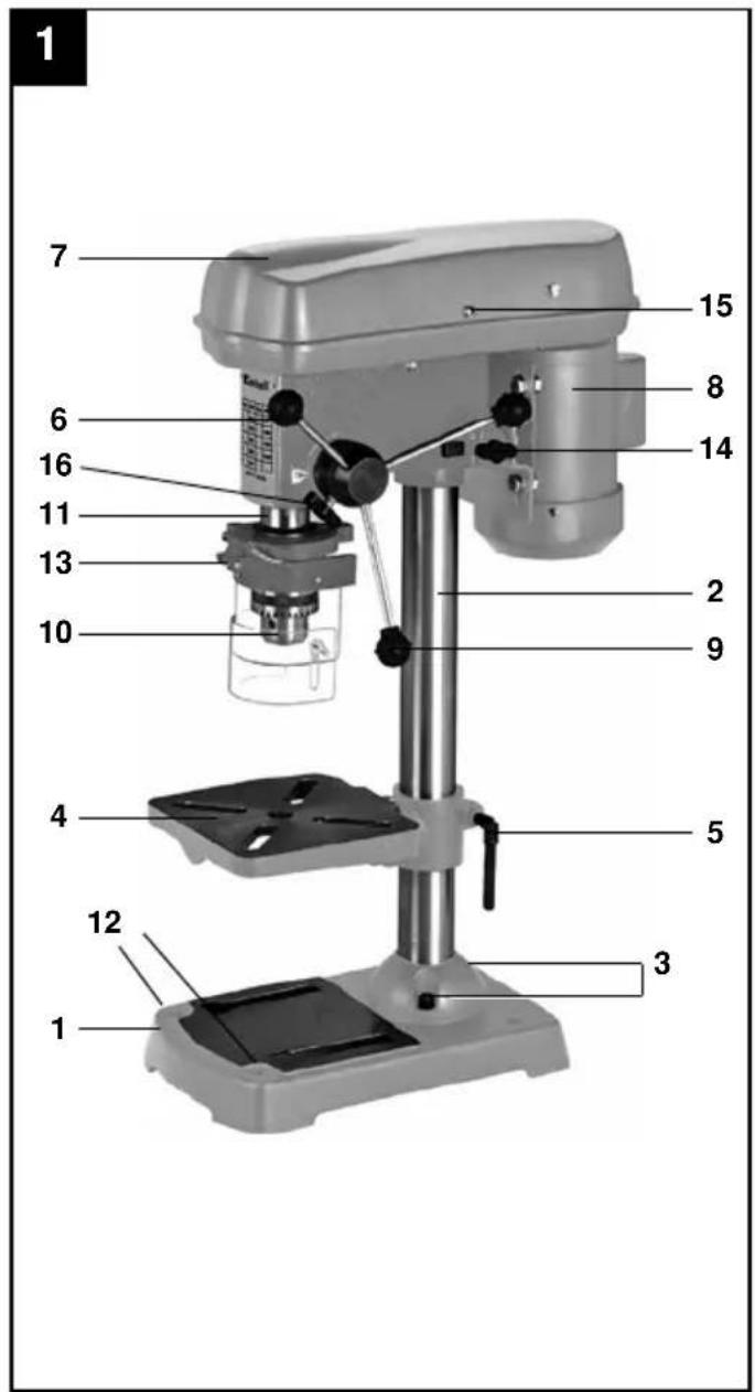
3. LAYOUT (FIG. 1 & 2)
- Machine base
- Pillar
- Fixing screw
- Drill table
- Clamping screw
- Machine head
- V-belt
- Motor
- Grip knobs
- Scroll chuck
- Spindle
- Mounting holes
- Folding chip guard
- Tightening screw
-
Screw
-
Clamping screw
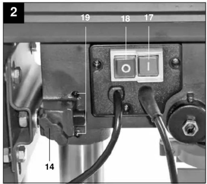
- ON switch
- OFF switch
- Grub screw
4. ITEMS SUPPLIED
- Open the packaging and take out the equipment with care.
- Remove the packaging material and any packaging and/or transportation braces (if available).
• Check to see if all items are supplied. - Inspect the equipment and accessories for transport damage.
- If possible, please keep the packaging until the end of the guarantee period.
IMPORTANT
The equipment and packaging material are not toys. Do not let children play with plastic bags, foils or small parts. There is a danger of swallowing or suffocating!
1x Drill Press
1x Scroll chuck
1x Drill chuck key
1x Folding chip guard
1x Drill table
1x Instruction Manual
1x Warranty Card
1x Warranty Sticker
1x Quick Start Guide
5. INTENDED USE
This drill press is designed for drilling metal, plastic, wood and similar materials. It is intended for domestic use only.
Food and harmful materials may not be processed with the equipment. The drill chuck is only designed for use with drill bits and tools with a shaft diameter of 1.5 to 16 mm, and for cylindrical tool shanks. Tools with a tapered shank can also be used. The equipment is intended for use by adults only.
The equipment is to be used only for its prescribed purpose. Any other use is deemed to be a case of misuse. The user / operator and not the manufacturer will be liable for any damage or injuries of any kind caused as a result of this.
Please note that our equipment has not been designed for use in commercial, trade or industrial applications. Our warranty will be voided if the equipment is used in commercial, trade or industrial businesses or for equivalent purposes.
6. TECHNICAL DATA
Nominal input voltage 230V \~ 50 Hz
| Power rating 500 W | |
| Operating mode S2 15 min. | |
| Motor speed 1,400 rpm | |
| Output speed 280 – 2,350 rpm | |
| Speed levels 9 | |
| Drill chuck mount B 16 | |
| Scroll chuck ∅ 1.5 - 16 mm | |
| Max. shaft diameter 16 mm | |
| Reach | 115 mm |
| Drill depth | 50 mm |
| Pillar diameter 46 mm | |
| Height | 650 mm |
| Weight | 21.5 kg |
| L_pA sound pressure level | 61.5 dB(A) |
| L_WA sound power level | 74.5 dB(A) |
| K_pA uncertainty | 3 dB |
| K_WA uncertainty | 3 dB |
Sound and vibration
Sound and vibration values were measured in accordance with EN 61029.
Load factor:
A load factor of S2 15 min (intermittent periodic duty) means that you may operate the motor continuously at its nominal power level (500 W) for no longer than the time stipulated on the specifications label (15 minutes ON period).
If you fail to observe this time limit the motor will overheat. During the OFF period the motor will cool again to its starting temperature.
Keep the noise emissions and vibrations to a minimum.
• Only use appliances which are in perfect working order.
• Service and clean the appliance regularly.
• Adapt your working style to suit the appliance.
• Do not overload the appliance.
• Have the appliance serviced whenever necessary.
- Switch the appliance off when it is not in use.
• Wear protective gloves.
Residual risks
Even if you use this electric power tool in accordance with instructions, certain residual risks cannot be ruled out. The following hazards may arise in connection with the equipment's construction and layout:
- Damage to hearing if no suitable ear protection is used.
7. BEFORE STARTING THE EqUIPMENT
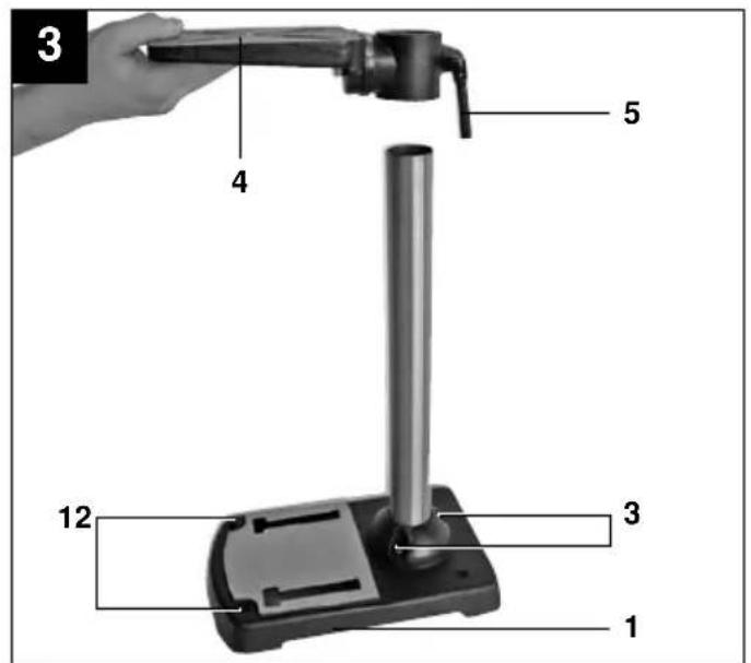
7.1. Assembling the machine (Fig. 1 & 2)
• Position the machine base (1).
- Fasten mounting flange with pillar (2) using three screws (3) and washers to drill base (1).
- Push the drill table (4) with drill table clamp shaft onto the pillar (2) (Fig. 3). Lock the drill table into the desired position using the clamping screw (5).
- Place drill head (6) with V-belt cover (7) and motor (8) onto the drill pillar and fasten using the Allen screws (19).
- Screw the three ball-shaped handles (9) onto the feeder cross handle.
Note: All bare parts are greased in order to protect them from corrosion. Before mounting the drill chuck (10) onto the spindle (11), both parts must be completely degreased using an environmentally friendly solvent. This ensures optimal transmission of power.
7.2. Installing the machine (Fig. 1)
Before you use the drill for the first time it must be permanently fixed in position. Use both mounting holes (12) in the base plate to do this. Ensure that the equipment is freely accessible for operation, adjustment and maintenance.
Note: The fixing screws may only be tightened to a point where they do not distort or deform the base plate. Excessive tension can lead to fracture.
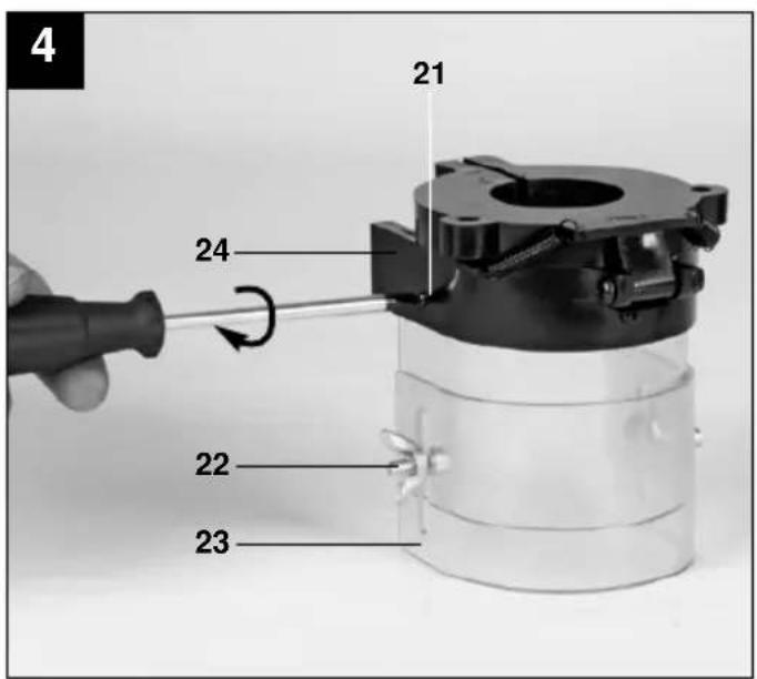
7.3. Folding chip guard (Fig. 4-6)
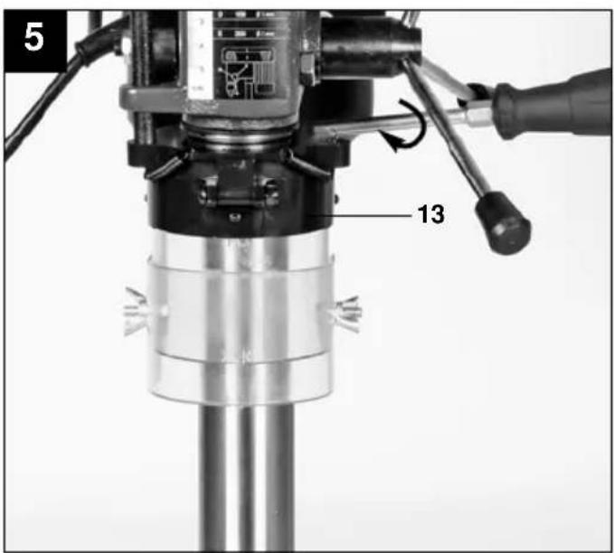
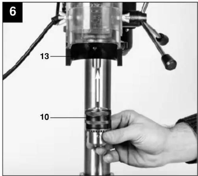
Unscrew the three screws (21). Push the transparent cover (23) into the groove of the red mounting frame (24) and fasten it again with the screws (21). Then use the clamping screw to fasten the folding chip guard (13) to the machine. Finally swing up the chip guard, push the scroll chuck (10) with a jerk onto the taper and check that the tool is securely seated. The height of the cover (23) is infinitely adjustable and can be locked using both thumb screws (22). The chip guard (13) can be flipped upwards to change drill bits, however ensure that the chip guard (13) is back in its initial position before restarting the equipment.
7.4. Prior to using the machine for the first time
Ensure that the voltage of the mains supply complies with the specifications on the rating plate. Connect the equipment only to a socket with the properly installed earthing contact. The drill is equipped with a no-volt trip that is designed to protect the operator from an undesired restart following a drop in voltage. Should this happen, the equipment must be physically restarted.
8. OPERATION
8.1. General (Fig. 2)
To switch on the equipment, push in the green On button "I" (17); the drill starts up. To switch off, press the red Off button
“O” (18); the drill shuts down. Ensure that you do not overload the equipment. If the sound of the motor drops in pitch during operation, it is being overloaded.
Do not overload the equipment to the point where the motor comes to a standstill.
8.2. Fitting tools to the drill chuck (Fig. 1)
Make sure that the power plug is removed from the socket-outlet before changing tools. Only cylindrical tools with the stipulated maximum shaft diameter may be clamped in the drill chuck (10). Only use a tool that is sharp and free of defects. Do not use tools whose shaft is damaged or which are deformed or flawed in any other way. Use only accessories and attachments that are specified in the operating instructions or have been approved by the manufacturer.
8.3. Using the quick-change drill chuck (Fig. 6)
Your drill is equipped with a gear-toothed drill chuck (10). In order to insert a drill bit, flip up the chip guard (13), insert the drill bit, then tighten down the drill chuck using the supplied chuck key.
Pull out the chuck key. Ensure that the clamped tool is firmly seated.
Important. Do not leave the chuck key in the clamp hole. Doing so will cause the chuck key to be catapulted out, which could cause injury.
8.4. Setting the speed (Fig. 1/8/9)
First switch the equipment off, then pull the power plug.
The various spindle speeds can be set by moving the V-belt.
Proceed as follows:
- Remove the screw (15) in order to open the Vbelt cover (7).
- Slacken the tightening screw (14) and push the motor (8) in the direction of the machine head.
- Move the V-belt to the desired position.
• Refer to table (Fig. 8) for the recommended speeds. - Tighten the V-belt by pushing the motor (8) away from the drill head (6). Screw the tightening screw (15) back down again. The tension is properly set when the V-belt flexes in the middle by approx. 1 cm when pressed.
- Close the V-belt cover and screw down using the screw (15). The V-belt cover (7) must always be locked tight, as the equipment is equipped with a safety switch that only allows the equipment to be turned when the V-belt cover (7) is closed.
Important. Never let the drill press run when the Vbelt cover is open. Always pull power plug before opening the cover. Never touch the V-belt when it is rotating.
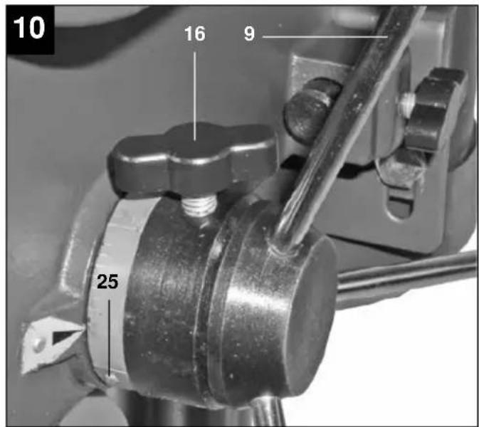
8.4.1 Drill depth stop (Fig. 1 & 10)
The drilling spindle has a swivelling scale ring (25) for setting the drill depth. Only adjust the setting when the equipment is at a standstill.
- Press the drilling spindle (11) downwards until the tip of the drill bit touches the workpiece.
- Slacken the clamping screw (16) and turn the scale ring (25) forwards until it stops.
- Turn the scale ring (25) back to the desired drill depth, then lock this setting into place using the clamping screw (16).
Important. When setting the drill depth of a cylindrical hole you must add the length of the drill tip.
8.4.2 Working speeds
Ensure that you drill at the proper speed. Drill speed is dependent on the diameter of the drill bit and the material it is made from.
The table below acts as a guide for selecting the proper speed for drill bits made from various materials.
Note: The rotational speeds shown are merely suggested alues.
| Drill bit ∅ Cast iron Steel Iron | Aluminium | Bronze |
| 3 – 1600 2230 – – | ||
| 4 1900 1200 1680 – – | ||
| 5 1530 955 1340 – – | ||
| 6 1270 800 1100 – – | ||
| 7 1090 680 960 – – | ||
| 8 960 600 840 – – | ||
| 9 850 530 740 – – | ||
| 10 765 480 670 – – | ||
| 11 700 435 610 – 2170 | ||
| 12 640 400 560 – 2000 | ||
| 13 590 370 515 2200 1840 | ||
| 14 545 340 480 2000 1700 | ||
| 16 480 300 420 1800 1500 | ||
| 18 425 265 370 1600 1300 | ||
| 20 380 240 335 1400 1200 | ||
| 22 350 220 305 1300 1100 | ||
| 25 305 190 270 1150 950 |
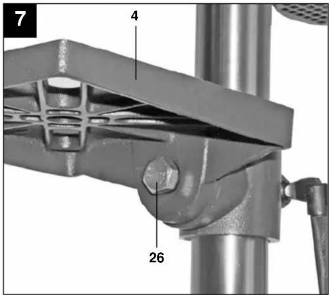
8.5. Setting the angle of the drill table (Fig. 7)
- Slacken the carriage bolt (26) under the drill table (4).
- Set the drill table (4) to the desired angle.
- Tighten down the carriage bolt (26) in order to lock the drill table (4) into this position.
8.6. Setting the height of the drill table (Fig. 1)
• Slacken the tightening screw (5).
- Set the drill table (4) to the desired height by pressing down or lifting up and simultaneously (gently) pushing to the left or right.
- Screw the tightening screw (5) back down again.
8.7 Clamping the workpiece
As a general rule, use a machine vice or another suitable clamping device to lock a workpiece into position. Never hold
the workpiece in place with your hand! When drilling, the workpiece should be able to travel on the drill table (Fig. 1/Item 4) for self-centering purposes. Ensure that the workpiece cannot rotate. This is best achieved by placing the workpiece/machine vice on a sturdy block.
Important. Sheetmetal parts must be clamped in to prevent them from being torn up. Properly set the height and angle of the drill table for each workpiece. There must be enough distance between the upper edge of the workpiece and tip of the drill bit.
8.8 Countersinking and center-drilling
With this drill you can also perform countersinking and center-drilling jobs. Please observe that countersinking should be performed at the lowest speed, while a high speed is required for centerdrilling.
8.9 Woodworking
Please note that sawdust must be properly evacuated when working with wood, as it can be a health hazard. Ensure that you wear a suitable dust mask when performing work that generates dust.
9. REPLACING THE POWER CABLE
If the power cable for this equipment is damaged, it must be replaced by the manufacturer or its aftersales service or similarly trained personnel to avoid danger.
10. CLEANING, MAINTENANCE AND ORDERING OF SPARE PARTS
Always pull out the mains power plug before starting any cleaning work.
10.1 Cleaning
- The drill is maintenance-free to a large extent. Keep the equipment clean. Pull the power plug before doing any cleaning and maintenance work on the appliance. Do not use any harsh, abrasive solvents to clean. Ensure that no liquid seeps into the equipment. Regrease all bare parts when the work is finished. The drill pillar, blank parts of the column, and the drill table especially should be regreased at regular intervals. Use a standard, acid-free lubricating grease to do this.
Important: Do not use your household trash can as a receptacle for oil and grease-soaked cleaning rags or grease and oil sludge. Dispose of these toxic materials in an environmentally friendly fashion. Regularly check and clean the ventilation holes. Store the equipment in a dry room. Should the equipment become damaged, do not try to repair it yourself. Leave this work to the hands of a qualified electrical technician.
• We recommend that you clean the equipment immediately after you use it.
- Clean the appliance regularly with a damp cloth and some soft soap. Do not use cleaning agents or solvents; these may be aggressive to the plastic parts in the appliance. Ensure that no water can get into the interior of the equipment.
10.2 Servicing
There are no parts inside the equipment which require additional maintenance.
10.3 Ordering spare parts
Contact our After Sales Support on 1300 922 271 and quote the following information on all orders for spare parts:
• Model/type of the equipment
• Article number of the equipment
• ID number of the equipment
- Spare part number of the required spare part
11. STORAGE
Store the equipment and accessories out of children's reach in a dark and dry place at above freezing temperature. The ideal storage temperature is between 5 and 30^ . Store the electric tool in its original packaging.
12. DISPOSAL AND RECYCLING
The equipment is supplied in packaging to prevent it from being damaged in transit. The raw materials in this packaging can be reused or recycled. The equipment and its accessories are made of various types of material, such as metal and plastic. Defective components must be disposed of as special waste. Ask your local council.
08/2012
42.505.45_11012 (01)
- Drill Press
- What your 1 year warranty means
- Welcome Section
- GENERAL SAFETY RULES
- SAVE THESE INSTRUCTIONS
- Work area
- Electrical safety
- Personal safety
- Power tool use and care
- Service
- Recommendation
- SPECIAL SAFETY RULES
- Ensure proper voltage
- Use a socket-outlet with earthing contact
- Extension cable
- Protection against electrical shock
- Protection against fire and explosion
- Handle the device with care
- Wear suitable work clothes and personal protection equipment
- Keep your work area neat and tidy
- Watch out for other persons
- Store the tools in a safe location
- Avoid overloading the device
- Maintain a steady foothold
- Pull out the mains plug
- Pull out the power plug.
- Avoid unintentional start-up
- Keep an eye on your work
- Check the tool for damage
- Maximum workpiece size
- Wear ear-muffs.
- Wear safety goggles.
- Important.
- LAYOUT (FIG. 1 & 2)
- ITEMS SUPPLIED
- IMPORTANT
- INTENDED USE
- TECHNICAL DATA
- Sound and vibration
- Load factor:
- Keep the noise emissions and vibrations to a minimum.
- Residual risks
- BEFORE STARTING THE EqUIPMENT
- Assembling the machine (Fig. 1 & 2)
- Installing the machine (Fig. 1)
- Folding chip guard (Fig. 4-6)
- Prior to using the machine for the first time
- OPERATION
- General (Fig. 2)
- Fitting tools to the drill chuck (Fig. 1)
- Using the quick-change drill chuck (Fig. 6)
- Setting the speed (Fig. 1/8/9)
- Drill depth stop (Fig. 1 & 10)
- Working speeds
- Setting the angle of the drill table (Fig. 7)
- Setting the height of the drill table (Fig. 1)
- Clamping the workpiece
- Countersinking and center-drilling
- Woodworking
- REPLACING THE POWER CABLE
- CLEANING, MAINTENANCE AND ORDERING OF SPARE PARTS
- Cleaning
- Servicing
- Ordering spare parts
- STORAGE
- DISPOSAL AND RECYCLING
Brand : TAURUS
Model : BT-BD 501
Category : Drill