
AC007UK-01 - Charger Sungrow - Free user manual and instructions
Find the device manual for free AC007UK-01 Sungrow in PDF.


| Product Type | AC Electric Vehicle (EV) Charger |
| Brand | Sungrow |
| Model | AC007UK-01 (Advanced) / AC007UK-01 L1 (Standard) |
| Dimensions (W x H x D) | 205 mm x 310 mm x 92 mm |
| Weight | 4.2 kg |
| AC Input | 230 Vac (±10%), 50/60 Hz |
| Max Charging Power | 7.4 kW |
| Max Charging Current | 32 A |
| Charging Connector | Type 2, cable length 7 m |
| Protection Features | Overload, over-temperature, surge protection Type II, PEN protection, DC leakage protection (6 mA), IP65, IK08 |
| Communication Interfaces | WLAN, RS485 (to external meter or inverter) |
| Authentication | RFID card or App (iEnergyCharge / iSolarCloud) |
| Charging Modes | Plug&Play, OCPP, EMS (solar-storage-charging), Scheduled Charging |
| Installation | Wall-mounted (default) or pole-mounted (optional) |
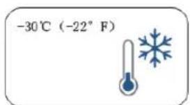
| Operating Temperature Range | -30°C to +50°C |
| Standby Power Consumption | < 5 W |
| Warranty | 3 years (standard) |
| Compliance | UKCA, EN/IEC 61851-1, EN/IEC 61851-21-2 |
| Maintenance & Cleaning | Clean with a dry cloth; do not spray water or liquids. Store charging connector in socket when not in use. |
| Safety Precautions | Do not install near flammable materials. Turn off circuit breaker before installation or cleaning. Do not touch terminals. Check with medical device manufacturer for compatibility. |
| Spare Parts & Repairability | Do not attempt to repair or disassemble. Contact Sungrow for spare parts and service. |
Frequently Asked Questions - AC007UK-01 Sungrow
User questions about AC007UK-01 Sungrow
0 question about this device. Answer the ones you know or ask your own.
Ask a new question about this device
Download the instructions for your Charger in PDF format for free! Find your manual AC007UK-01 - Sungrow and take your electronic device back in hand. On this page are published all the documents necessary for the use of your device. AC007UK-01 by Sungrow.
USER MANUAL AC007UK-01 Sungrow
natural_image
White SunRICH electric water heater connected to a black cable (no visible text or symbols)All Rights Reserved
All Rights Reserved
No part of this document can be reproduced in any form or by any means without the prior written permission of Sungrow Power Supply Co., Ltd (hereinafter "SUNGROW").
Trademarks
SUNGROW and other Sungrow trademarks used in this manual are owned by SUNGROW.
All other trademarks or registered trademarks mentioned in this manual are owned by their respective owners.
Software Licenses
- It is prohibited to use data contained in firmware or software developed by SUNGROW, in part or in full, for commercial purposes by any means.
- It is prohibited to perform reverse engineering, cracking, or any other operations that compromise the original program design of the software developed by SUNGROW.
Privacy Protection
• Information contained in this manual is the private property of Sungrow Power Supply Co., Ltd. No part of this manual may be transmitted in any form without the prior written permission of Sunlight Power Co., Ltd. Internal reproduction is allowed only for product evaluation or other appropriate purposes.
- We declare that the network account and password data stored in the equipment system are only used for remote control and monitoring of the equipment and will not be transmitted to any third-party data platform without the user's permission.
- At our EV charger, we take the privacy of our customers seriously. We only collect charging information in accordance with applicable privacy laws and regulations.
Disposal
After the service life of the charger ends, please dispose of it in accordance with the applicable electrical waste disposal act at the installation location. It can also be returned to Sun-grow Power Supply Co., Ltd., but the relevant expenses shall be borne by your party.
About This Manual
The manual mainly contains product information, as well as guidelines for installation, operation, and maintenance.
Target Group
This manual is intended for qualified technicians who are responsible for the installation, operation, and maintenance of the charger, and end users who need to check charger parameters.
A qualified technician is required to meet the following requirements:
- Knowledge of electronics, electricity, and machinery, and be familiar with electrical and mechanical schematic diagrams.
- Training in the installation and commissioning of electrical equipment.
- Be able to quickly respond to hazards or emergencies that occur during installation and commissioning.
- Be familiar with local standards and relevant safety regulations of electrical systems.
- Read this manual thoroughly and understand the safety instructions related to operations.
EMC
In some cases, even if the equipment is in accordance with the standard emission limits, it can have an impact in certain application areas (some sensitive equipment is placed in the same location; the equipment is installed close to a radio or TV receiver), and the operator is obliged to take appropriate action to correct this situation.
How to Use This Manual
Please read this manual carefully before using the product and keep it properly in a place for easy access.
All contents, pictures, marks, and symbols in this manual are owned by SUNGROW. No part of this document may be reprinted by the non-internal staff of SUNGROW without written authorization.
Contents of this manual may be periodically updated or revised, and the actual product purchased shall prevail. Users can obtain the latest manual from support.sungrowpower.com or sales channels.
Symbols
This manual contains important safety instructions, which are highlighted with the following symbols, to ensure personal and property safety during usage, or to help optimize the product performance efficiently.
! DANGER
Indicates high-risk potential hazards that, if not avoided, may lead to death or serious injury.
WARNING
Indicates moderate-risk potential hazards that, if not avoided, may lead to death or serious injury.
CAUTION
Indicates low-risk potential hazards that, if not avoided, may lead to minor or moderate injury.
NOTICE
Indicates potential risks that, if not avoided, may lead to device malfunctions or financial losses.

"NOTE" indicates additional information, emphasized contents, or tips that may be helpful, e.g., to help you solve problems or save time.
Contents
All Rights Reserved ....I
About This Manual....II
1 Safe Introductions .... 1
2 Introduction ....3
2.1 Introduction....3
2.2 Model and Nameplate....3
2.3 Appearance and Dimensions....4
2.4 LED Signals .... 4
2.5 Electrical Connection Ports ....5
2.6 System Topology ....5
3 Installation 7
3.1 Installation Requirements....7
3.2 Unpacking and Inspection ....8
3.3 Installation Tools....10
3.4 Electrical Connection 11
3.4.1 Circuit Diagram 11
3.4.2 AC Cable Connection 11
3.4.3 RS485 Communication Connection ....14
3.5 Wall-Mounted Installation 16
3.6 Pole-Mounted Installation....20
3.6.1 Foundation Installation ....20
3.6.2 Pole Installation 21
4 Inspection before Commissioning ....25
5 Troubleshooting 26
6 iEnergyCharge App ....31
6.1 Download and Installation ....31
6.2 Sign-up and Log in....31
6.3 Add a Charger....32
6.4 Charging View....35
6.4.1 Start/Stop Charging....36
6.4.2 Scheduled Charging....36
6.4.3 Device Settings....36
6.5 Account 39
6.5.1 Charging Bills ......39
6.5.2 Scheduled Charging....40
6.5.3 Customer Service 41
6.5.4 Network Settings....42
6.5.5 Firmware Management....43
6.5.6 Device Connection ....44
6.5.7 Charge Cards ....44
6.5.8 Settings....45
7 Commissioning via iSolarCloud 47
8 Appendix ....48
8.1 Technical Data ....48
8.2 Quality Assurance ....50
8.3 Declaration of Conformity....50
8.4 Firmware Update....50
8.5 Contact Information .... 51
1 Safe Introductions
This manual contains important instructions for SUNGROW charger that shall be followed during installation, operation, and maintenance. Please review all warnings and notices before installing and using the charger.
! WARNING
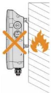
Do not install or use the charger near flammable, explosive, harsh or combustible materials, chemicals, or vapors.
WARNING
Turn off the power supply at the circuit breaker before installing or cleaning the charger.
NOTICE
Use the charger only within the operation steps and parameters specified in this manual.
NOTICE
Never spray water or any other liquid directly onto the charger body or the charging connector. Store the charger in the connector socket to prevent unnecessary damage.
NOTICE
Do not attempt to disassemble, repair, tamper with or modify the charger. Contact SUNGROW for any repair or modification.
NOTICE
Do not use the charger if it is defective, appears cracked, frayed, broken or otherwise damaged, or fails to operate. Please contact SUNGROW in time.
NOTICE
Be careful when transporting the charger. Do not subject it to strong force or impact or pull, twist, tangle, drag, or step on the charger to prevent damage to it or any components.
NOTICE
Do not touch the end terminal of the charger with any part of your body or metal objects.
NOTICE
Use of charger may affect or impair the operation of any medical or implantable electronic devices, such as implantable cardiac pacemakers or implantable cardioverter defibrillator. Please check with your electronic device manufacturer concerning the effects of the charger on such electronic devices before using the charger.
2 Introduction
2.1 Introduction
The AC007UK-01 / AC007UK-01 L1 charger (hereinafter "charger") is used for AC charging of electric vehicles (EV/PHEV) and can be either wall-mounted or pole-mounted, with the following advantages:
Ease of Use
EV drivers can start and stop charging via RFID card or App. When the vehicle is fully charged, the charging will stop. The charger also supports plug&play charging, which means the charging starts automatically as soon as the charging connector is plugged into the vehicle.
Smart and Easy Management
In addition to the LED lights on the charger that indicate charging status, EV drivers can visualize and control the charging session remotely via iEnergyCharge or iSolarCloud.
Sustainability
With an IP65 rating, the charger is water and dust proof, allowing for outdoor use and maintenance.
2.2 Model and Nameplate

The charger comes in two versions for different use cases:
- AC007UK-01 (hereinafter referred as "the advanced version")
- AC007UK-01 L1 (hereinafter referred as "the standard version")
2.3 Appearance and Dimensions
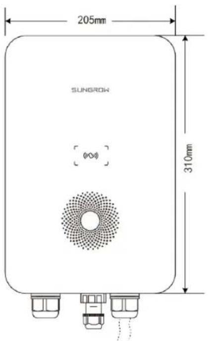
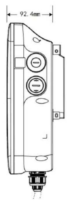
figure 2-1 Appearance and dimensions
2.4 LED Signals
table 2-1 LED Signals
| Indicator Indicator | |
| Standby | Blue indicator flashes slowly, on for 1 s and off for 4s; circulating |
| Charging | Blue indicator breathes, on for 1s and off for 1s; circulating |
| Charging stops Blue indicator is steady on | |
| Ready to charge | Blue indicator flashes quickly, on for 0.5s and off for 0.5s; circulating |
| Charging reservation | Blue indicator is on for 3s and red indicator is on for 3s |
| Power-on self-test | Blue indicator is on for 1s and red indicator is on for 1s |
| Charger software upgrading | Blue indicator flashes quickly |
| Swiping Card | Blue light is on for 5 times with an interval of 0.2s |
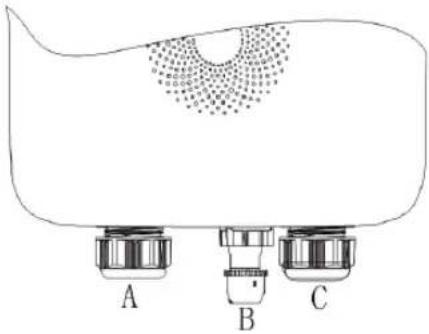
2.5 Electrical Connection Ports
natural_image
Diagram of a mechanical component with three labeled parts (A, B, C) and a dotted circular pattern on the surface (no text or symbols beyond labels)figure 2-2 Port Diagram
table 2-2 Label Explanation
| Label Explanation |
| A AC input (AC connection) |
| B RS485 external communication |
| C Charging cable output (Charging cable connection) |
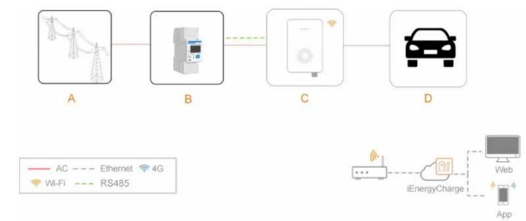
2.6 System Topology
Stand-alone EV Charger
flowchart
graph LR
    A["A"] --> B["B"]
    B --> C["C"]
    C --> D["D"]
    D --> E["iEnergyCharge"]
    E --> F["App"]
    style A fill:#f9f,stroke:#333
    style B fill:#ccf,stroke:#333
    style C fill:#cfc,stroke:#333
    style D fill:#fcc,stroke:#333
    style E fill:#ffc,stroke:#333
    style F fill:#fcc,stroke:#333
figure 2-3 System topology diagram of EV charger
| Position | Description | Note |
| A | Utility grid | TT, TN-C, TN-S, TN-C-S. |
| B | Smart Energy Meter Optional (DDSU666). | |
| C | Charger | AC007UK-01 L1 |
| D Electric vehicle | - | |
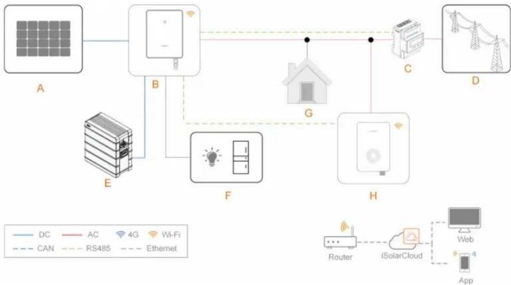
Solar-Storage-Charging Solution
flowchart
graph TD
    A[" Solar Panel A "] --> B[" Home "]
    B --> C[" Router"]
    C --> D[" iSolarCloud "]
    D --> E[" App "]
    B --> F[" Furniture "]
    F --> G[" Home "]
    G --> H[" Router "]
    H --> I[" Web "]
    style A fill:#99CCFF
    style B fill:#99CCFF
    style C fill:#99CCFF
    style D fill:#99CCFF
    style E fill:#99CCFF
    style F fill:#99CCFF
    style G fill:#99CCFF
    style H fill:#99CCFF
    style I fill:#99CCFF
figure 2-4 System topology diagram of the solar-storage-charging solution
| Position | Description | Note |
| A | PV strings | Compatible with monocrystalline silicon, polycrystalline silicon, and thin-film modules without grounding. |
| B Inverter | - | |
| C | Smart Energy Meter | A smart energy meter that monitors power usage and helps to avoid power outages caused by peak electricity during home charging. |
| D | Utility grid | TT, TN, TN-C-S, TN-S, TN-C. The type of grid grounding system depends on local regulations. |
| E | Battery A Li-ion battery. | |
| F | Backup loads Protected house loads directly connected to the inverter. | |
| G Normal loads | Non-protected house loads. They will be disconnected in case of grid failure. | |
| H | Charger | AC007UK-01 |

For Sungrow's solar-storage-EV charging solution, please refer to user manuals of related inverters.
3 Installation

WARNING
Respect all local standards and requirements during mechanical installation.

CAUTION
Any damage or malfunction with the charger caused by negligence or improper use will not be eligible for service and replacement under the warranty.
3.1 Installation Requirements
Location Requirements
Select an optimal mounting location for safe operation, long service life and expected performance.
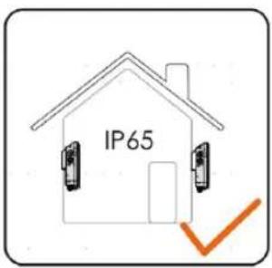
• The charger with protection rating IP65 can be installed both indoors and outdoors.
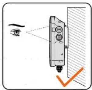
- The charger should be installed at a place where the LED signals can be easily seen, and is convenient for electrical connection, operation, and maintenance.
Environment Requirements
- There must be no flammable hazards or ignition risks.
- The mounting location must be inaccessible to children.
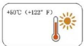
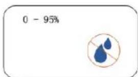
- The ambient temperature and relative humidity must meet the following requirements.
- Avoid exposure to direct sunlight, rainwater and snow.
- The charger should be well-ventilated for good air circulation.
- The mounting location must be away from living area. The charger will emit noises during operation that might be perceived as disturbing.
Carrier Requirements
The mounting structure where the charger is installed must comply with local/national standards and guidelines.
Ensure that the installation surface is solid enough to bear 4.5 times the weight of the charger and is suitable for the dimensions of the inverter.
natural_image
Diagram of a fire extinguisher with no visible text or symbolsAngle Requirements
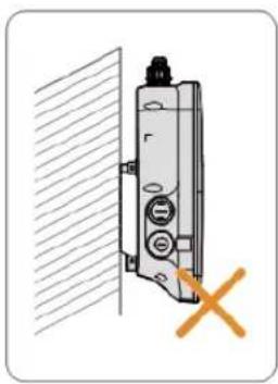
• Install the charger vertically.
- Do not install the charger horizontally, tilted or upside down.
• Do not install the charger on a tilted surface.
natural_image
Diagram of a door lock mechanism with a cross mark indicating no change, shown against a wall and diagonal hatching (no text or symbols)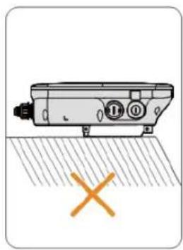
natural_image
Diagram of a mechanical device with labeled ports and a cross symbol, no readable text or symbols present.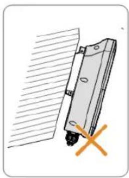
natural_image
Diagram of a mechanical component with a cross mark and hatched background (no text or symbols)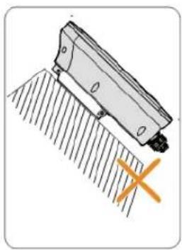
natural_image
Diagram of a mechanical component with hatched texture and a cross mark, no visible text or symbols3.2 Unpacking and Inspection
i
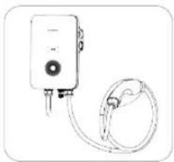
After receiving the product, check whether the appearance and structural parts of the device are damaged, and check whether the packing list is consistent with the actual ordered product. If there are problems, do not install the device and contact your distributor first. If the problem persists, contact SUNGROW in time.
natural_image
Line drawing of a medical or electrical device with a coiled cable and connector (no text or symbols)A
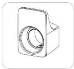
natural_image
Technical line drawing of a mechanical component with a circular recess and rectangular body (no text or symbols)B
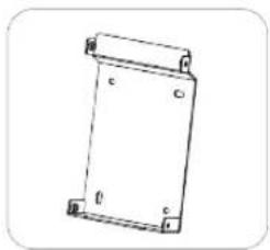
natural_image
Simple line drawing of a rectangular frame with labeled corners (no text or symbols)C
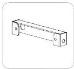
natural_image
Technical line drawing of a rectangular mechanical component with mounting holes and a central rod (no text or symbols)D
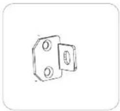
natural_image
Simple line drawing of two mechanical components with circular holes (no text or symbols)E
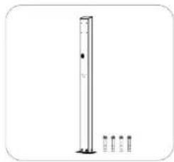
natural_image
Simple line drawing of a vertical pole with four small vertical supports at the base (no text or symbols)F
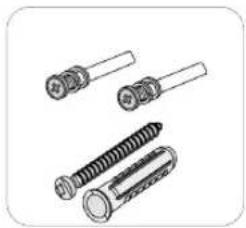
natural_image
Illustration of multiple types of screws and fasteners (no text or symbols)G
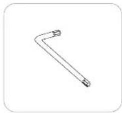
natural_image
Simple line drawing of a bent tool or bracket (no text or symbols)H
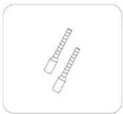
natural_image
Simple line drawing of two cylindrical objects with segmented ends, no text or symbols present.|
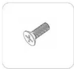
natural_image
Simple line drawing of a bolt (no text or symbols)J
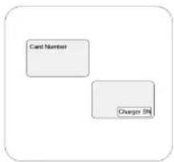
K
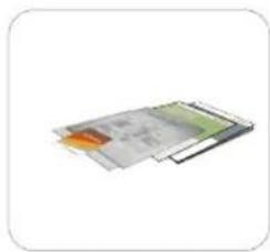
natural_image
Illustration of a layered electronic device with colored components (no text or symbols visible)L
natural_image
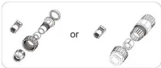
Exploded view diagram of mechanical components, showing exploded and assembled parts (no text or symbols)M
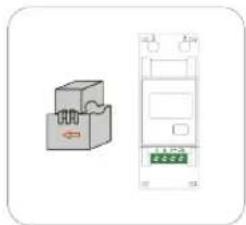
natural_image
Illustration of a two-port electrical connector with a green indicator light and red arrow (no text or symbols)N
table 3-1 Label Descriptions
| Item Name Quantity | ||
| A AC-Charger 1 | ||
| B Charging cable bracket 1 | ||
| C Backplate 1 | ||
| D Upper mounting plate 1 | ||
| E Lower mounting plate 2 | ||
| F Mounting pole (optional) | 1 ( not included in scope of delivery ) | |
| G Combination screw and expansion screw | 4, 7 (wall-mounted); 11, 0 (pole-mounted) | |
| H L-shaped spanner 1 | ||
| I Wire end ferrule | 1~2 | |
| J Countersunk screw | 6 | |
| K RFID card 2 | ||
| L | Quick Installation Guide, Warranty Card, and Certificate of Conformity | 1, 1, 1 |
| M RJ45 screw connector 1 | ||
| N | DDSU666 Smart Energy Meter (optional) | 1 |

The scope of delivery does not include the optional mounting pole (F), this item must be ordered separately.
3.3 Installation Tools
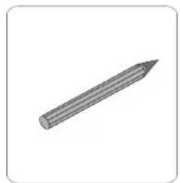
natural_image
Simple 3D illustration of a sharpened pencil (no text or symbols)A
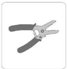
natural_image
Illustration of two pliers with black handles and metal tips (no text or symbols)B
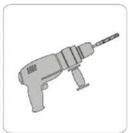
natural_image
Illustration of a handheld electric drill (no text or symbols)C
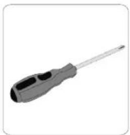
natural_image
Illustration of a screwdriver with a black handle and metallic shaft (no text or symbols)D
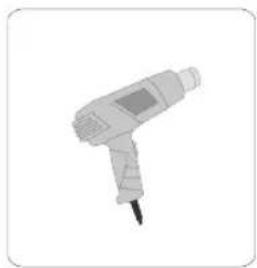
natural_image
Illustration of a handheld electric shaver with a black tip (no text or symbols)E
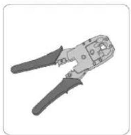
natural_image
Illustration of a pair of crimping tools (no text or symbols visible)F
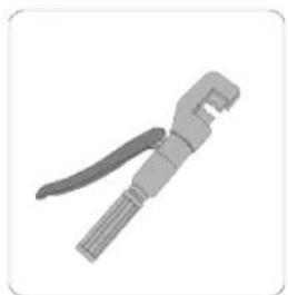
natural_image
Gray mechanical tool with threaded handle and clasp (no text or symbols visible)G
natural_image
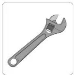
Illustration of an adjustable wrench with a handle and spout (no text or symbols)H
table 3-2 Label Descriptions
| Item Name Specification | |
| A Marker | - |
| B Wire stripper | - |
| C Hammer drill | 6, 12 |
| D Phillips screwdriver | M3, M4, M5 |
| E Heat gun | - |
| F RJ45 crimping tool | - |
| G Hydraulic plier | 2.5-6 mm^2 |
| H Adjustable spanner | - |
3.4 Electrical Connection
3.4.1 Circuit Diagram
flowchart
graph TD
    A["GRID"] -->|N| B["CUU"]
    A -->|L| B
    A -->|PE| B
    B -->|Input_N| C["Output_N"]
    B -->|Input_L| D["Output_L"]
    B -->|PE| E["PE"]
    B -->|CP| F["CP"]
    B --> G["LEAK_C"]
    B --> H["CT"]
    H --> I["CHARGING CONNECTOR TYPE 2"]
    I --> J["E"]
    K["ROB"] --> L["A"]
    M["ESP32"] --> N["B"]
    style A fill:#f9f,stroke:#333
    style I fill:#ccf,stroke:#333
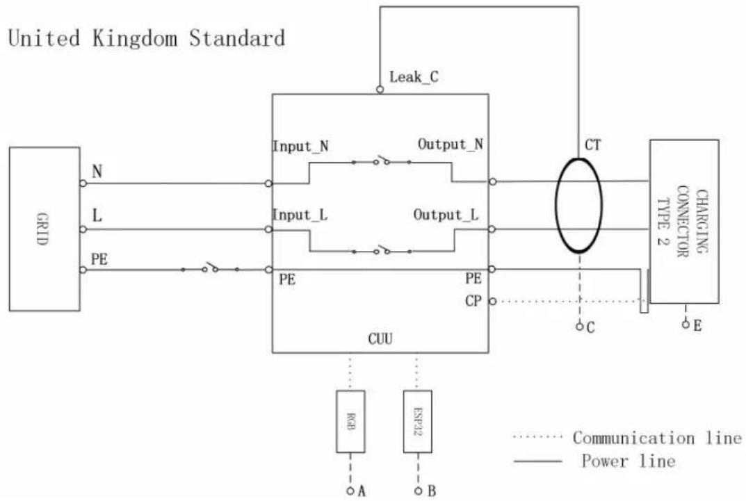
figure 3-1 Circuit diagram(United Kingdom)
table 3-3 Label Descriptions
| Label Description |
| A The LED lights that indicates the status of the charger |
| B ESP32 module for Wi-Fi communication |
| C CT for leakage current detection |
| E Charging connector Type 2 |
NOTICE
The charger already integrates a DC residual-current device (RCD) with a rated residual current of 6 mA. However, the charger also requires a type A RCD of 30 mA to operate. Each charger in the system must be individually connected to the utility grid through an RCD and a miniature circuit breaker.
3.4.2 AC Cable Connection
AC Cable Requirement
Cable cross-section: 3 × 6 mm^2
Step 1 Place the charger face-down on a clean and flat surface.
Step 2 Loosen the screws that secure the back cover plate. (M3 screws, torque: 0.5 ± 0.1 ~N · m )
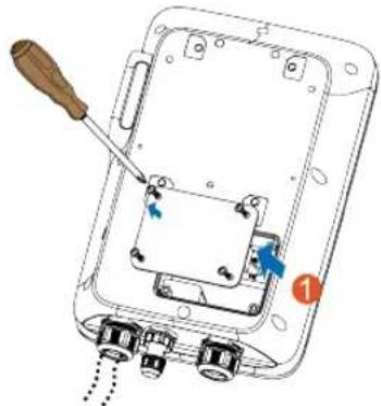
natural_image
Diagram of a device with a screwdriver inserted into a housing, showing internal components and wiring (no text or symbols)Step 3 Plug the cable into the port of the power supply which is at the leftmost.
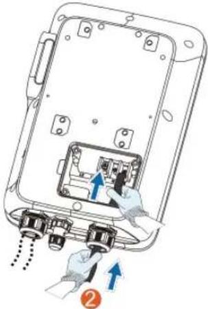
natural_image
Diagram of a device showing internal components and directional arrows, no text or symbols presentStep 4 Adjust the cable to a suitable length, and strip off the insulation of the cable to prepare for cable connection terminals.
1 Strip off the insulation from the end of each wire.
2 Insert the copper core of the stripped end of the wire into the copper lug.
3 Tighten the copper lug using a hydraulic plier.
4 Select a heat-shrink tubing that matches the diameter of the wire.
The length of the tubing should be about 2 mm longer than the length of the copper lug's wire tube.
5 Place the heat-shrink tubing on the copper lug until it completely covers the copper lug's wire hole.
6 Activate heat-shrink tubing using a heat gun.
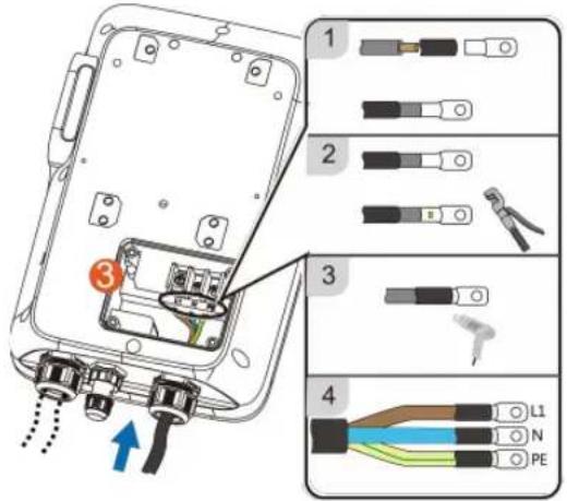
Color Terminal
Brown L1
Blue N
Yellow-green PE
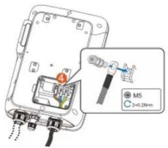
Step 5 Connect each crimped terminal (OT2.5-5) and tighten them using a screwdriver. (Torque: 3 ± 0.2 N·m)
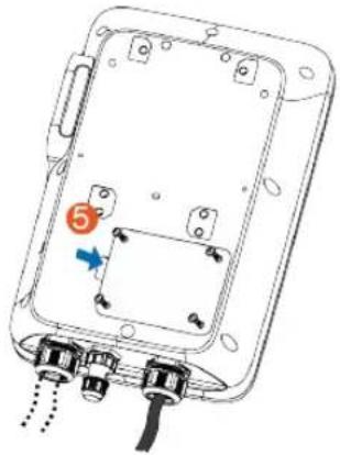
Step 6 Put the back cover plate back in place and tighten the screws to secure it.
natural_image
Technical diagram of an electronic device showing internal components and wiring (no text or symbols)-- End
3.4.3 RS485 Communication Connection
i
In the stand-alone usage application scenario, you may connect an RS485 cable to the meter to enable ALM function.
i
For the Residential Hybrid + AC Charging Solution, the RS485 communication connection is needed to connect the AC Charger to SUNGROW's 1-phase inverter (SHRS).
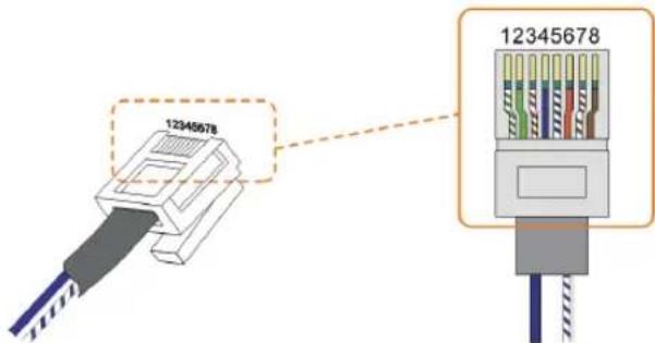
Step 1 Crimp both ends of the Ethernet cable using a crimping tool.

You will receive one of the following two RJ45 terminal components, please refer to the actual product you receive.
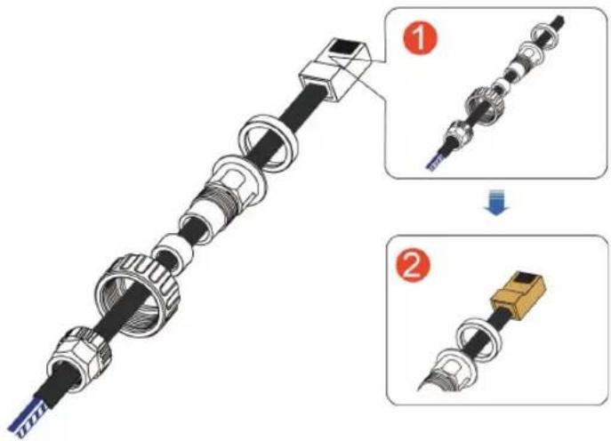
figure 3-2 RJ45 screw connector(A)
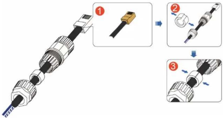
figure 3-3 RJ45 screw connector(B)

Ensure that the blue wire and the blue-white wire is correctly crimped. The blue wire (PIN 4) connects to 485B, and the blue-white wire (PIN 5) connects to 485A.
Step 2 Insert the RJ45 connector to the RJ45 jack.
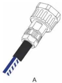
Step 3 Install seals for the Ethernet cable in sequence.
natural_image
Illustration of a connector with a blue and black cable, labeled 'A' (no text or symbols on the diagram itself)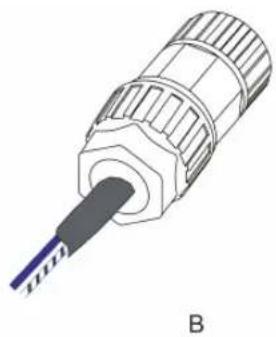
natural_image
3D illustration of a screwdriver with labeled section B (no text or symbols on the diagram itself)
Ensure that the cable is secured.
Step 4 Connect the charger to a Smart Energy Meter or a SUNGROW Hybrid inverter.
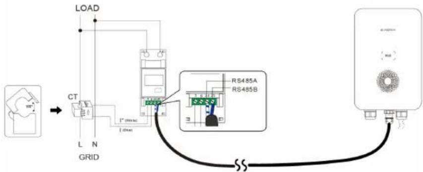
figure 3-4 Connect to a Smart Energy Meter
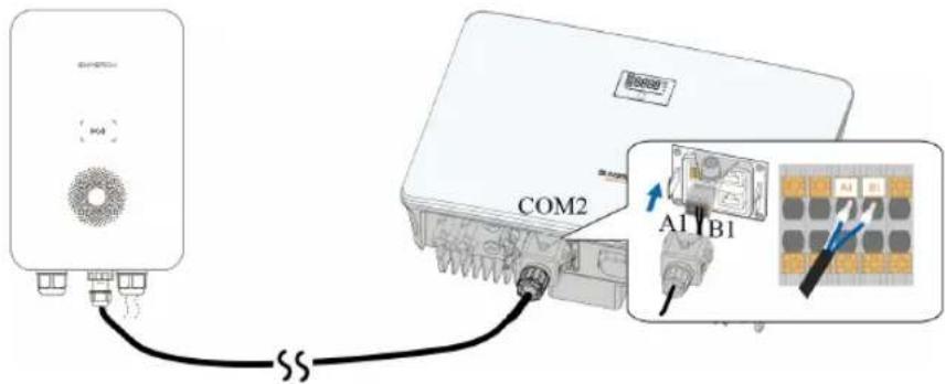
figure 3-5 Connect to an inverter(SHRS)
-- End
3.5 Wall-Mounted Installation
Install the charger on the wall using the provided wall-mounting bracket and expansion screw sets.

• Installation height of the charger from ground: 1.1m recommended
- The load-bearing capacity of the installation carrier must be at least 4.5 times the weight of the charger.
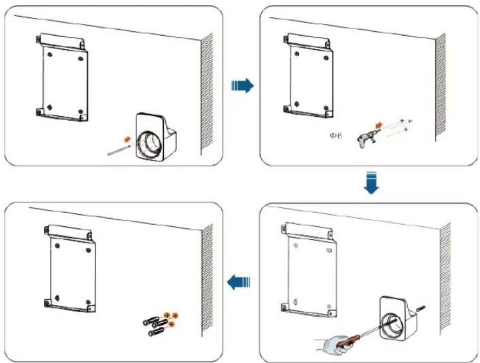
Step 1 Install the backplate.
1 Hold the backplate in the desired position on the wall and mark the positions of the drill holes.
NOTICE
Before drilling the hole for the backplate, locate and avoid water pipes and electrical wires in the wall.
2 Drill holes at the marked positions using a hammer drill. (Diameter: 6 mm; depth: 45 mm)
3 Insert the dowel into the holes.
4 Place the backplate on the wall and tighten the screws using a screwdriver to secure the backplate.
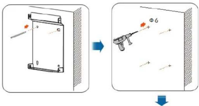
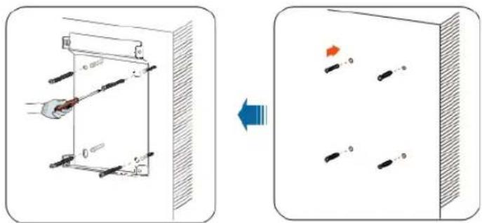
natural_image
Diagram showing a device with a handle and control panel before and after assembly, with no visible text or symbols.Step 2 Install the charging cable bracket.
1 Hold the charging cable bracket in the desired position on the wall and mark the positions of the drill holes.
2 Drill holes at the marked positions using a hammer drill.
3 Insert the dowel into the hole.
4 Place the charging cable bracket on the wall, and tighten the screws to secure the charging cable bracket using a screwdriver.
flowchart
graph TD
    A["Initial component with bolted part"] --> B["Arrow to valve mechanism"]
    B --> C["Downward arrow to test circuit"]
    C --> D["Final assembly with tool and screwdriver"]

It is recommended that the charging cable bracket be positioned at the lower right side of the charger, about 20 cm away from the charger. The distance shall be adjusted according to the actual situation.
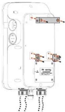
Step 3 Mount the charger.
1 Secure the upper mounting plate and the lower mounting plate on the back of the charger using a screwdriver. (Torque: 1.2 ± 0.1 N·m)
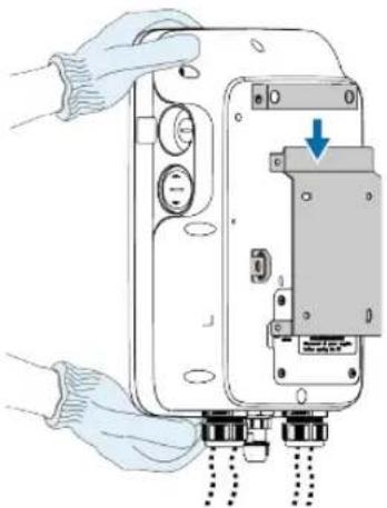
2 Hang the charger onto the backplate.
natural_image
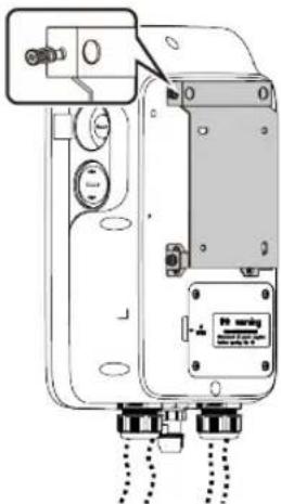
Illustration of hands installing or adjusting a device with a blue arrow indicating a component (no text or symbols present)3 Secure the upper and lower mounting plates to the backplate with screws. (Torque: 1.2 ± 0.1 N·m).
natural_image
Technical line drawing of a mechanical device with mounting holes and a control panel (no text or symbols)-- End

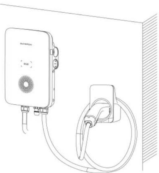
Installation height of the connector socket from ground: 1.1m recommended, from charger:0.5m recommended
natural_image
Line drawing of a wall-mounted device connected to a cable, showing ports and wiring (no text or symbols)figure 3-6 Wall-mounted charger
3.6 Pole-Mounted Installation

It is recommended to install the pole on a solid support surface (such as concrete or tarmac). If conditions do not permit, please install the foundation first, and then install the mounting pole.
3.6.1 Foundation Installation
The base should be 100 mm above the ground, and the exterior dimensions of the front, back, left, and right side columns should be greater than 100 mm. Ensure that there are openings for cables.
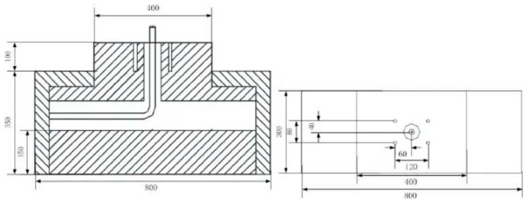
figure 3-7 Front view and top view (unit: mm)
3.6.2 Pole Installation
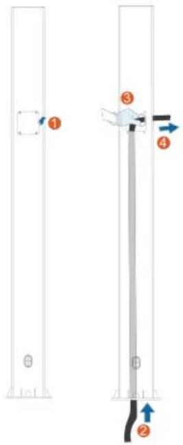
Step 1 Connect the AC cable.
1 Remove the cover plate on the back of the pole using a cross screwdriver.
2 Lead the AC cable through the bottom into the pole.
3 Grab the AC cable when it reaches the cover plate and take out the end of the cable from the AC cable outlet.
4 Pull the cable out to an appropriate length and close the cover plate.
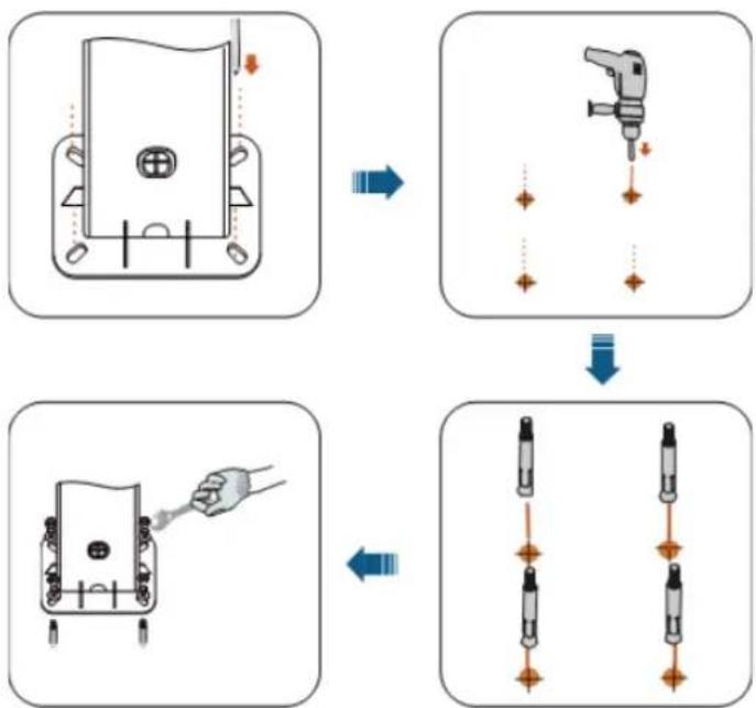
Step 2 Mount the charger.
1 Place the pole on a solid and flat surface, and mark the positions of the drill holes.
2 Drill holes at the marked positions using a hammer drill. (Diameter: 12 mm; depth: 70 mm)
3 Insert the dowel into the holes.
4 Tighten the expansion screw using a screwdriver.
flowchart
graph TD
    A["Component with switch"] --> B["Tool with screwdriver"]
    B --> C["Pin alignment with arrows"]
    C --> D["Close-up of pin alignment"]
    D --> E["Arrow pointing inward"]
5 Check whether the pole is firmly installed.
Step 3 Install the backplate and the charging cable bracket.
1 Align the holes in the backplate with the holes drilled in the pole, and secure the backplate to the pole with screws.
2 Align the holes in the bracket with the holes drilled in the pole, and secure the bracket to the pole with screws.
3 Check whether the backplate and the charging cable bracket are firmly installed.
Step 4 Install the upper mounting plate and lower mounting plate.
1 Place the charger face-down on a clean and flat surface, and secure the upper and lower mounting plates to the pole using a screwdriver.
2 Ensure that the upper mounting plate and the lower mounting plate are firmly installed.
3 Hang the charger onto the backplate.
4 Secure the upper and lower mounting plates to the backplate.
5 Check whether the charger is correctly installed on the pole.
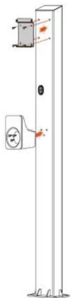
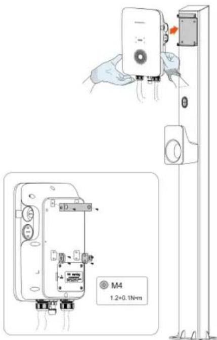
-- End
natural_image
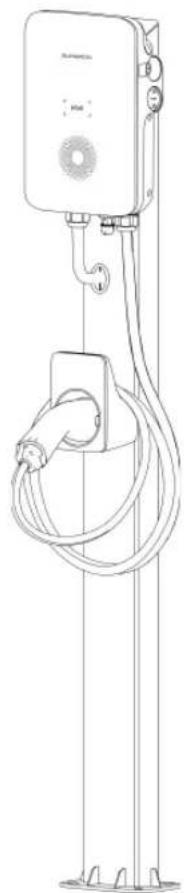
Line drawing of a vertical electric shock absorber with coiled cable and terminal connectors (no text or symbols)figure 3-8 Pole-mounted charger
4 Inspection before Commissioning
table 4-1 Requirements before commissioning
| Item | Description |
| Location | The charger is correctly mounted at a place that is convenient for operation and maintenance. |
| Charger The charger is firmly and securely installed. | |
| Cable | Cables are correctly and firmly connected, and are adequately protected from damage. |
| Current leakage protection | The AC input's current leakage protection switch is reasonable. |
| Clearance | The charger has sufficient cooling space and there is no other stuff or components are left on the top of the charger. |
Step 1 Ensure that all requirements are met before commissioning.
Step 2 Turn on the current leakage protection switch of the AC input.
Step 3 Power on the charger.
The blue LED blinks slowly which indicates the charger is in standby mode.
-- End
5 Troubleshooting
table 5-1 Fault Resolution
| Problem Possible Cause | Solution | ||
| Overvoltage | 1 The grid voltage at the input end of the charger exceeds.2 The grid voltage is still above after overvoltage. | Usually, the charger will be re-connected to the grid once the voltage falls inside the range of 251V~209V for 2 minutes. If the problem occurs repeatedly:1 Measure the actual grid voltage, and contact local power company for solutions if the grid voltage is above.2 Contact Sungrow Customer Service if the problem persists. | |
| Undervoltage | 1 The grid voltage at the input end of the charger is below.2 The grid voltage is still below after undervoltage. | Usually, the charger will be re-connected to the grid once the voltage falls inside the range of 251V~209V for 2 minutes. If the problem occurs repeatedly:1 Measure the actual grid voltage, and contact the local power company for solutions if the grid voltage is below.2 Check if the AC cables are firmly connected.3 Contact Sungrow Customer Service if the problem persists. | |
| Overfrequency | 1 The mains AC frequency exceeds 63 Hz.2 The grid frequency is still above 61 Hz after overfrequency. | Usually, the charger will be re-connected to the grid once the grid returns to normal. If the problem occurs repeatedly:1 Measure the actual grid frequency, and contact the local power company for solutions if the grid frequency is above 61 Hz.2 Contact Sungrow Customer Service if the problem persists. | |
| Underfrequency | 1 The mains AC frequency is below 47 Hz.2 The grid frequency is still below 49 Hz after underfrequency. | Usually, the charger will be re-connected to the grid once the grid returns to normal. If the problem occurs repeatedly:1 Measure the actual grid frequency, and contact the local power company for solutions if the grid frequency is below 49 Hz.2 Contact Sungrow Customer Service if the problem persists. | |
| EV | Leakage current | The DC leakage current is above 6 mA | |
| Overcurrent | Output current is above over-current point.Mark : Adjust the over-current value following the actual current, below 20 A, over-current value is actual current + 2 A;Above 20 A, over-current value is 1.1 times the actual current; If there is no define current, which is 1.1 time the max. current. | 1 Stop charging and pull out the charging connector.When the charger returns to normal, try charge again. If the problem occurs repeatedly, contact the EV manufacturer's customer service.2 Stop charging and pull out the charging connector. Contact Sungrow Customer Service if the problem persists. | |
| Problem | Possible | Cause | Solution |
| Charger | Relay adhension | The relay is stuck and cannot be disconnected. | Restart the charger and try again.If the problem occurs repeatedly, contact Sungrow Customer Service. |
| Leakage current detection circuit failure | 1 The CT terminal has bad connection or the CT is malfunctioning.2 The RCD circuit is abnormal. | ||
| Relay overtemperature | The temperature of the main relay is too high. It might be a hardware problem. | ||
| CP failure | Abnormal CP circuit on the main board | ||
| Wiring | Input terminal overtemperature | 1 The input terminal is loosely connected which causes bad connection.2 The cable's current-carry-ing capacity does not meet the requirements. | 1 Ensure that the AC cable is tightly connected, that the cable used meets requirements, and L and N wires are correctly connected.2 Contact Sungrow Customer Service if the problem persists. |
| Reverse polarity | L and N wires are connected reversely. | ||
| Meter communication abnormal | No communication between the meter and the charger for 1 minute. | Check whether the RS485 cable between the meter and the charger is properly connected, or turn off the load balancing function. | |
| CT fault | The bus current measured by the CT is smaller than the actual output current of the charger. Something abnormal with the CT. | Replace the CT, or turn off the load balancing function. | |
table 5-2 LED Signals that indicates abnormal conditions
| Charger Status LED Signals | |
| Leakage current | Red light is on for 0.5s, off for 0.5s, and flashes 4 times, and then off for 3s. Cyclic |
| CP failure | Red light is on for 0.5s, off for 0.5s, and flashes 5 times, and then off for 3s. Cyclic |
| Overcurrent | Red light is on for 0.5s, off for 0.5s, and flashes 6 times, and then off for 3s. Cyclic |
| Relay adhesion | Red light is on for 0.5s, off for 0.5s, and flashes 7 times, and then off for 3s. Cyclic |
| Leakage current circuit abnormal | Red light is on for 0.5s, off for 0.5s, and flashes 8 times, and then off for 3s. Cyclic |
| Input terminal over-temperature | Red light is on for 0.5s, off for 0.5s, and flashes 9 times, and then off for 3s. Cyclic |
| Relay over-heat | Red light is on for 0.5s, off for 0.5s, and flashes 10 times, and then off for 3s. Cyclic |
| Undervoltage | Red light is on for 0.5s, off for 0.5s, and flashes 11 times, and then off for 3s. Cyclic |
| Overvoltage | Red light is on for 0.5s, off for 0.5s, and flashes 12 times, and then off for 3s. Cyclic |
| Over-frequency | Red light is on for 0.5s, off for 0.5s, and flashes 13 times, and then off for 3s. Cyclic |
| Under-frequency | Red light is on for 0.5s, off for 0.5s, and flashes 14 times, and then off for 3s. Cyclic |
| Security chip failure | Red light is on for 0.5s, off for 0.5s, and flashes 16 times, and then off for 3s. Cyclic |
| CT abnormal | Red light is on for 0.5s, off for 0.5s, and flashes 17 times, and then off for 3s. Cyclic |
| ALM Meter communication abnormal | Red light is on for 0.5s, off for 0.5s, and flashes 18 times, and then off for 3s. Cyclic |
| Alarms (ground alarm, disassembly alarm, reverse phase alarm and etc.) | Red light is on |

If the above faults cannot be removed, please contact Sungrow.
6 iEnergyCharge App
iEnergyCharge App is a tool that allows users to operate and manage their EV chargers. Users can complete account settings and charger configuration, manage charge cards, operate the charger, and reach customer service on the App.

Depending on the version of iEnergyCharge you are using, the user interface might be slightly different.
6.1 Download and Installation
Operating System:
- Android 6.0 or later
- iOS 11 or later
Option 1
Download the App from the below application stores and install it on your device:
- Google Play
- App Store
Option 2
Scan the QR code below, and download and install the App by following the onscreen instructions.

6.2 Sign-up and Log in
Step 1 Open the iEnergyCharge App, and tap Sign up.
Step 2 Enter an email address, and tap Next.
Step 3 Find the verification code sent by the system in your email inbox. Then, go back to the App, enter the verification code, and tap Next.
Step 4 Enter a password, and the sign-up process is now completed. You will then go to the App's Home screen.
-- End
6.3 Add a Charger
To add a charger to your account on the iEnergyCharge App for operation and management, you need to set up a reliable network connection between the devices first.
Requirements:
• The charger is powered on;
- Stable WLAN networks are available.

- The charger's WLAN can only be on for 15 minutes. If the network is off, you can restart the charger and connect again.
- To avoid potential interference, it is recommended to enable airplane mode on your mobile device when connecting to the charger's WLAN.
Step 1 Tap Add device on the Home screen.
Step 2 Scan the QR code on the side of the charger, and then, in the "Add device" dialog, tap Establish Connection.
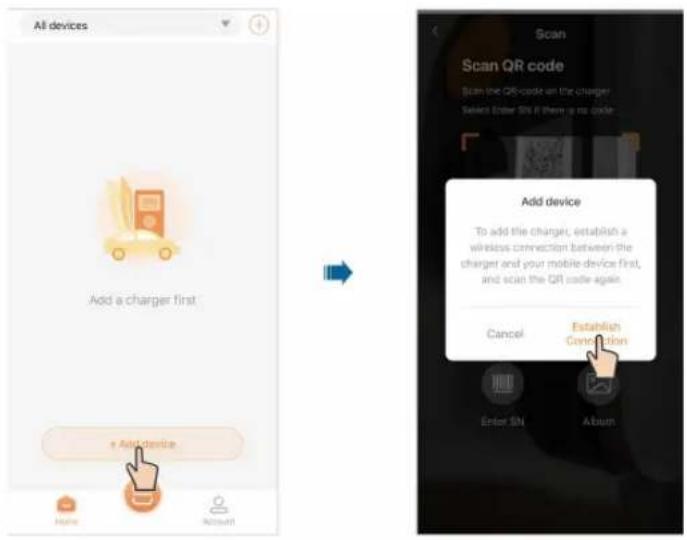
Step 3 Go to WLAN settings on your mobile device, and connect to the charger's WLAN. The charger's WLAN is named as its S/N, and the password is "admin123" or no password required.
![WLAN connection 1. Go to the WLAN settings, and connect to the Wi-Fi hotspot with the name: [A2292804847] ... 2. Please refer to the user manual if login password is required, and restart the charger if you cannot find the hotspot. WLAN MY NETWORKS sungrow OTHER NETWORKS DIRECT-B2-HP OfficeJet Pro 8730 DIRECT-hdMFC-J2330DW_BRe1cb Axxxxxxxxx OrayBo 68 Other... Apps Using WLAN & Cellular](/content/2026/05/895953/images/72d65dced6c5f196fc42d22570e5b535c8e26d9da431d737a388afc373dc3c59.jpg)
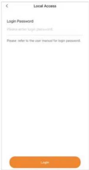
Step 4 Once connected successfully, go back to the App and enter the login password, which should be "SGC666", or "the 4-digit PIN code" on the back of the charge card. Then, tap Log in.
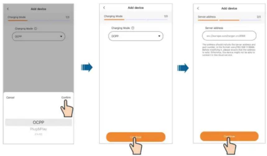
Step 5 Select a charging mode based on your needs, and tap Continue. Then, set the server address, and tap Continue.
flowchart
graph TD
    A["Add device"] --> B["Charging Mode 1/3"]
    B --> C{OCPP}
    C -->|Confirm| D["Cancel"]
    C -->|Confirm| E["Confirm"]
    D --> F["OCPP Plug&Play"]
    F --> G["OK/OK"]

    H["Add device"] --> I["Charging Mode 1/3"]
    I --> J{OCPP}
    J -->|Confirm| K["Cancel"]
    J -->|Confirm| L["OK/OK"]

    M["Add device"] --> N["Server address 2/3"]
    N --> O["Server address wx://europe.wx/harger.cn.3068"]
    O --> P["The address should include the server address and port number in the Hotcat: was/202.188.1.18888. Before modifying it, please ensure that the address is valid. Otherwise, the device might not be able to navigate to the cloud service."]
    P --> Q["OK/OK"]
Mode Description Note
| OCPP Charge using the stand-alone EV charger. | The default mode for AC007UK-01 L1.By default, AC007UK-01 L1 does not support EMS charging. Contact customer service for assistance if you require EMS charging. |
| Plug&Play Plug and charge. | - |
| EMS Available when used with the SUN-GROW solar-energy storage-EV charging system. | The default mode for AC007UK-01. |

If the charging mode is set to "EMS", you need to enter the password, which is the 4-digit PIN code on the RFID card.

Default server address: wss://europe.suncharger.cn:20038. If you want to add a non-SUNGROW charger, enter the server address provided by the operator.
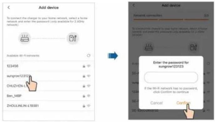
Step 6 Connect the charger to a stable WLAN network, where you are required to enter the correct password.
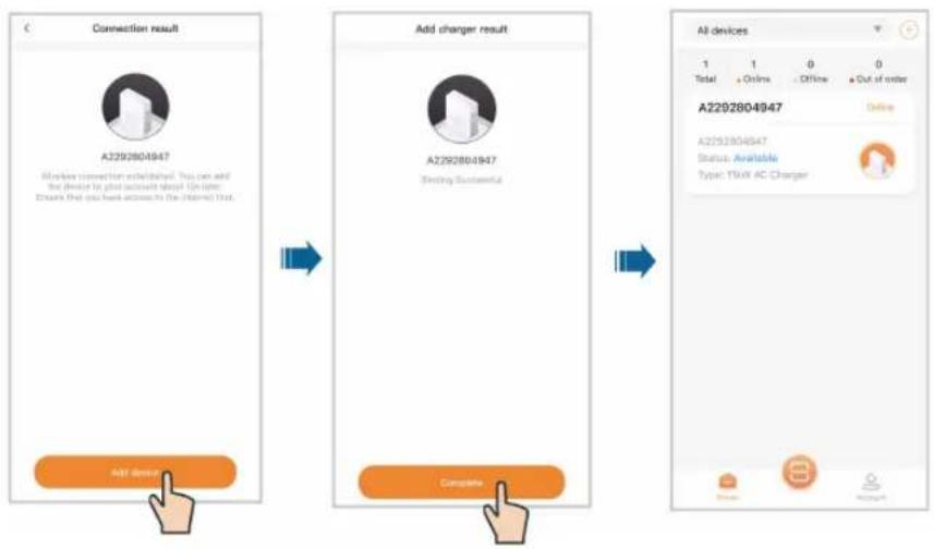
Step 7 After network connection is established successfully, tap Add device. The device is now added to your account successfully. Then, tap Complete, and you will be directed to the App's Home screen. You can check the status of the charger you have added on this screen.

Disconnect from the charger first, and connect to the router's WLAN network.
flowchart
graph TD
    A["Add device"] --> B["Add charger result"]
    B --> C["Complete"]
-- End
6.4 Charging View
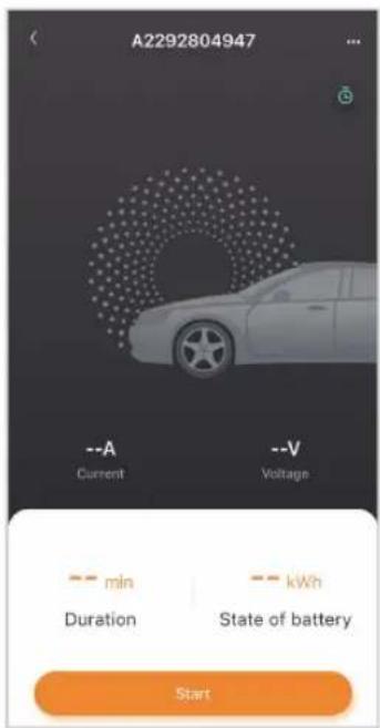
After a charger has been added, you can start a charging session or modify charging settings remotely on the charging screen of the App.
On the Home screen, choose an available charger that has been added before and tap it. You will then go to the charging screen.
6.4.1 Start/Stop Charging
Start Charging
Tap Start on the charging screen to start a charging session. During the charging process, you can view the real-time charging current and voltage, charging time, and battery status.
Stop Charging
If needed, you can tap Stop on the charging screen to stop charging immediately.
6.4.2 Scheduled Charging
Step 1 Tap in the upper right corner of the charging screen to go to "Scheduled charging".
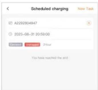
Step 2 Tap New task in the upper right corner of this screen. Here you can create a new scheduled charging task.
-- End
6.4.3 Device Settings
Tap in the upper right corner of the charging screen to go to "Device settings".
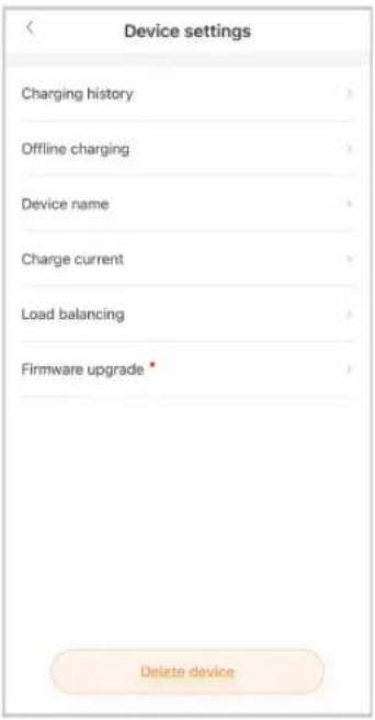
Delete device
Tap Delete device at the bottom of the screen to delete the current charger.
Charging history
Tap Charging history to view the records of charging history.
Offline charging
Requirements:
- Your phone and the charger have connection to the Internet.
• The charger is available. - At least one RFID charge card is available.
Tap Offline charging. To enable offline charging, tap the toggle button in the upper left corner, and select the charge card you want to use.
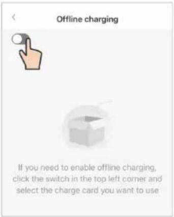

If you have not added an RFID charge card, or you need to add a new card, tap "Add card" at the top right and follow the onscreen instructions to complete the process.

If you switch off offline charging, the respective RFID charge cards must be associated with the charger once again for recognition.
Device name
Tap Device name. Enter a name, and tap Save to set the device name.
Charge current
Tap Charge current. Set the charging current, and tap Save to effect the setting.

The regulated charging current applies only to the current charging session.
Load balancing
Requirements:
• The charger is online.
• The charger is not in use.
- The charger has connected to a power-controlling device.
Tap Load balancing. Set the "Monitoring method" to Smart Meter, and set the "Meter Type" and "Max. Home Load Current" based on the actual situation. Then, tap Set to effect the settings.
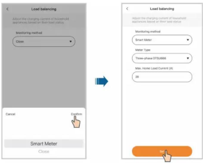

Load balancing is available only for SUNGROW energy meters. Contact the customer service for more details.
Firmware upgrade
Requirements:
- Your phone and the charger have connection to the Internet.
• The charger is available.
• There is a new version of the firmware.
Tap Firmware upgrade. Tap Update to start remote firmware upgrade.

To ensure proper functionality of the charger, it is recommended to keep the firmware up to date.
6.5 Account
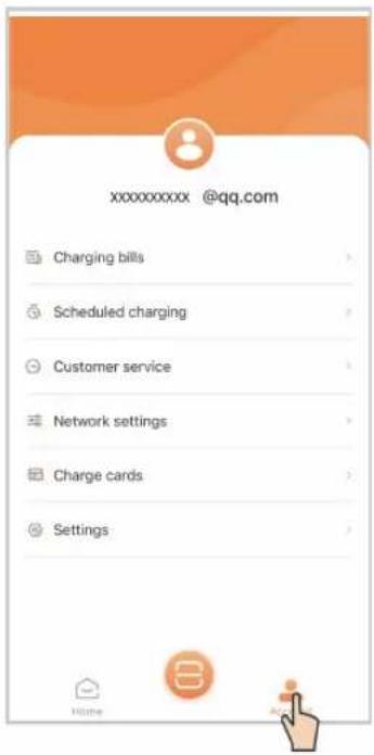
Tap Account in the bottom navigation bar. You will then see the screen shown below.
6.5.1 Charging Bills
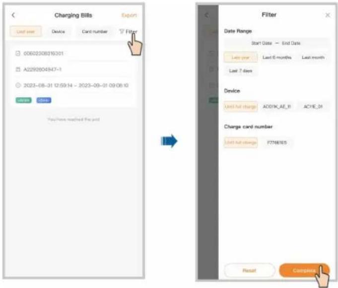
Step 1 Tap Charging bills.
Step 2 Tap Filter at the top of the screen, and you can view charging bills by date, device, and charge card number.
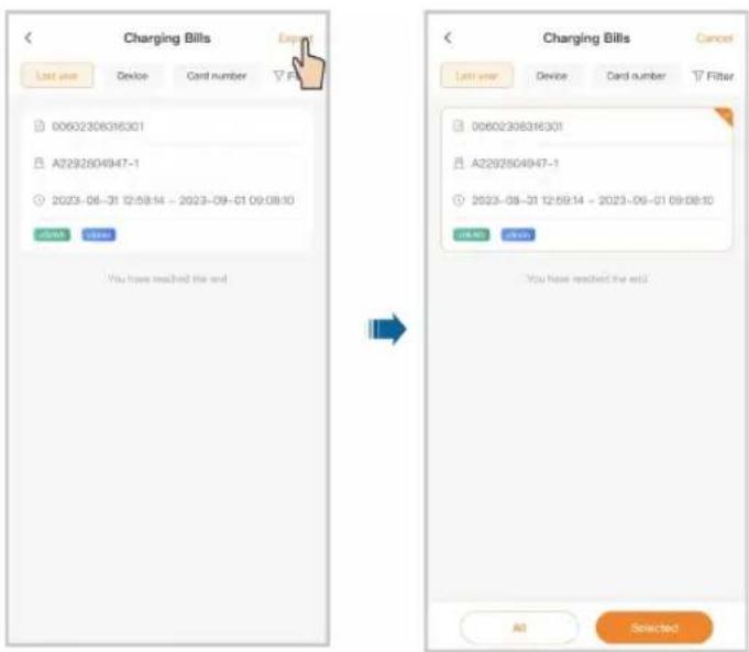
Step 3 Tap Export in the upper right corner of the screen to export the charging bills you need.
-- End
6.5.2 Scheduled Charging
Step 1 Tap Scheduled charging.
Step 2 Tap New task in the upper right corner to create a scheduled charging task. Select the device and tap Add.
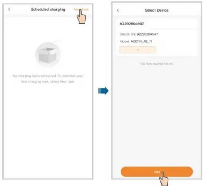
Step 3 Set the start date, start time, and duration, and tap Start. A scheduled charging task is now created.
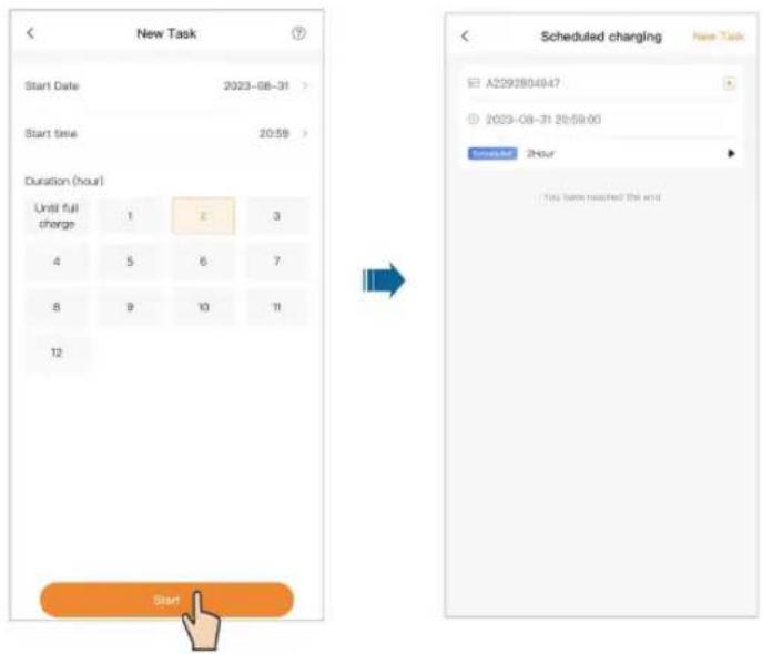
-- End
6.5.3 Customer Service
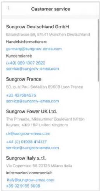
Tap Customer service. You can find the contact information for SUNGROW in some regions on this screen.
6.5.4 Network Settings
If the WLAN network has changed, please re-configure the network connection for the charger by following the below steps.

To avoid potential interference, it is recommended to enable airplane mode on your mobile device when connecting to the charger's WLAN.
Step 1 Tap Network settings, scan the QR code on the side of the charger, and connect the device.
Step 2 Go to WLAN settings on your mobile device, and connect to the charger's WLAN. The charger's WLAN is named as its S/N, and the password is "admin123" or no password required.
Step 3 Once connected successfully, go back to the App and enter the login password, which should be "SGC666", or "the 4-digit PIN code" on the back of the charge card. Then, tap Login.
Step 4 Choose another stable wireless network. Enter the password and connect the charger to the network.
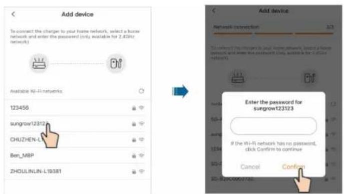
-- End
6.5.5 Firmware Management

"Firmware Management" is accessible to the Administrator account, please contact your distributor or SUNGROW for the Administrator account and password.
Step 1 Tap Firmware Management.
Step 2 Select the device and the module to be upgraded.
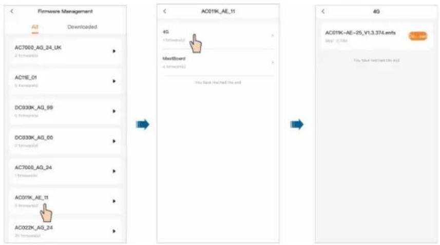
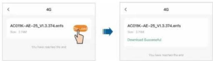
Step 3 Choose the target firmware package and tap Download to download it.
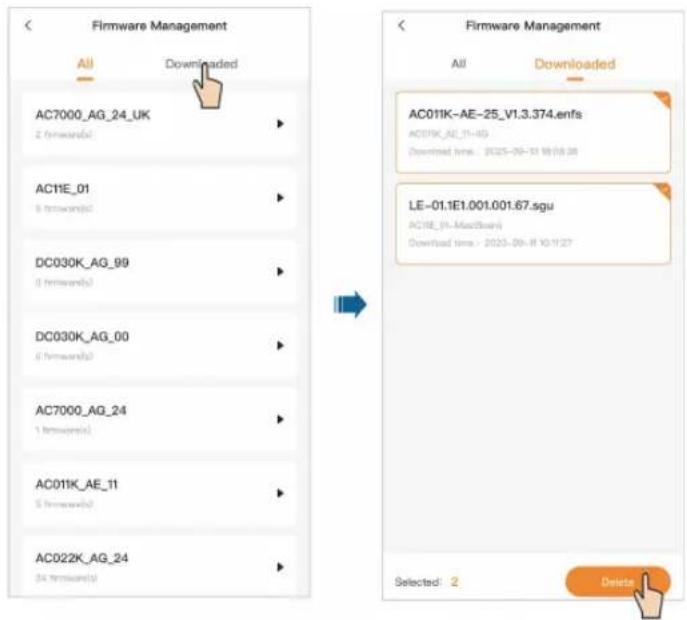
Step 4 Go back to "Firmware Management". Tap Download, and you can see the firmware package you have downloaded. You can also select the downloaded firmware package and delete it.
-- End
6.5.6 Device Connection
The "Device Connection" function is used to enable the near-end O&M of the charger.

"Device Connection" is accessible to the Administrator account, please contact your distributor or SUNGROW for the Administrator account and password.
Step 1 Tap Device Connection, scan the QR code on the side of the charger and connect the device.
Step 2 Go to WLAN settings on your mobile device, and connect to the charger's WLAN. The charger's WLAN is named as its S/N, and the password is "admin123" or no password required.
Step 3 Go back to the App, and you will automatically go to the interface for near-end O&M.
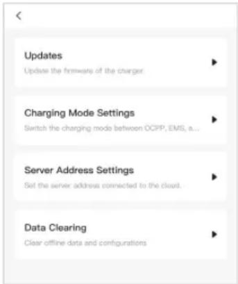
1 Tap Updates. Here you can select the firmware package that has been downloaded, and tap Start to Upload to start firmware upgrade. For details on firmware package download, see "6.5.5 Firmware Management".
2 Tap Charging Mode Settings. You can change the charging mode for the current charger on this screen as needed.

If the charging mode is set to "EMS", you need to enter the password, which is the 4-digit PIN code on the RFID card.
3 Tap Server Address Settings. You can change the server address for this charger on this screen as needed.
4 Tap Data Clearing. You can clear the cache data in the charger.
-- End
6.5.7 Charge Cards
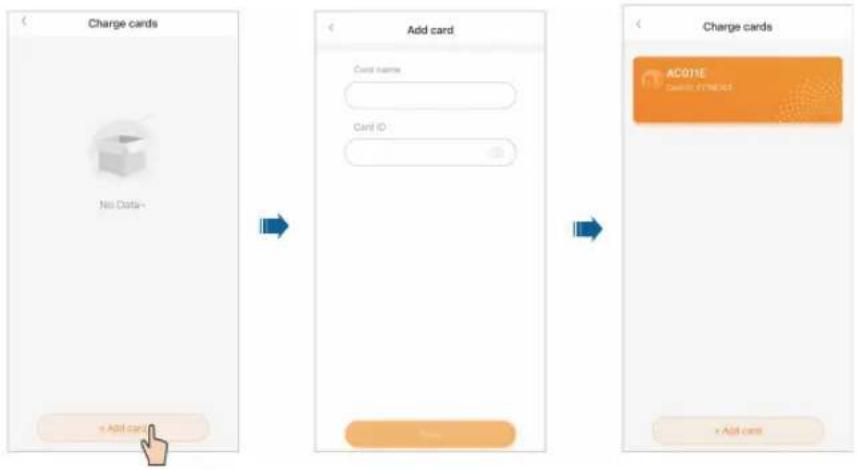
Step 1 Tap Charge cards.
Step 2 Tap Add card at the bottom of the screen. Then, enter the card name and ID, and tap Save. The card is now added successfully.
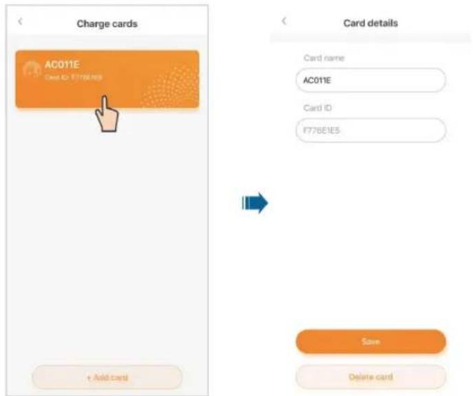
Step 3 Tap the card that has been added, and go to "Card details". Here you can edit the card name or delete the card.
-- End
6.5.8 Settings
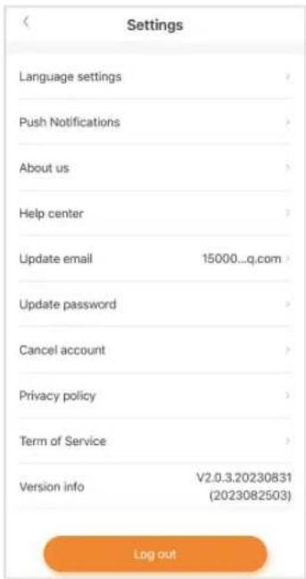
Tap Settings. Here you can complete settings related to the language of the App, push notifications, email, and password. You can tap Log out to log out of the current account.
7 Commissioning via iSolarCloud

- If the charger works under EMS mode, proceed with commissioning on the iSolarCloud App.
- If the charger works under EMS mode, make sure it is connected to the inverter via the RS485 cable. For details on the RS485 cable connection, see "3.4.3 RS485 Communication Connection".
Download the iSolarCloud App
Option 1
Search for "iSolarCloud" in an application store, and download and install the App on your device.
- Google Play (Android)
- App Store (iOS)
Option 2
Scan the following QR code to download and install the App according to the prompt information.

Commissioning on the iSolarCloud App
For detailed instructions for commissioning, please refer to the user manual of the inverter:
1-Phase Hybrid Inverter User Manual
8 Appendix
8.1 Technical Data
table 8-1 Technical Data
| Technical parameters | AC007UK-01 L1 AC007UK-01 | |
| AC Input | ||
| Nominal grid voltage 230 Vac (±10%) | ||
| Nominal grid frequency | 50 Hz / 60 Hz | |
| AC Output | ||
| Max. charging power | 7.4 kW | |
| Max. charging current | 32 A | |
| Protection & Function | ||
| Integrated DC fault current detection | Yes, 6 mA | |
| Overload protection | Yes | |
| Over-temperature protection | Yes | |
| Surge protection AC Type II | ||
| PEN protection | Yes | |
| Mechanical impact protection | IK08 | |
| ALM (Adaptative load management) | Yes | |
| User interface & Communication | ||
| Display LED indicator and App | ||
| Authentication | RFID-card / iEnergyCharge App | RFID-card / iSolarCloud App |
| Charging mode | - | Eco charging / Fast Charging / Scheduled Charging / Customized charging |
| Communication interface | WLAN, RS485 (to external meter) | WLAN, RS485 (to Sungrow inverter) |
| Communication protocol | OCPP 1.6 J | |
| Gerneral data | ||
| Dimensions (W*H*D) | 205 mm * 310 mm * 92 mm | |
| Weight 4.2 kg | ||
| Installation method | Wall-mounting (default)Stand column (optional) | |
| Degree of protection | IP65 | |
| Operating ambient temperature range | -30 °C - 50 °C | |
| Allowable relative humidity range | 5% - 95% (non-condensing) | |
| Cooling method | Natural convection | |
| Max. operating altitude | ≤ 2000 m | |
| AC cable specification | Cross-section 6 mm2 * 3 | |
| Charging connector AC Type 2 | ||
| Charging cable length | 7 m | |
| Standby self-consumption | < 5 W | |
| Warranty 3 years (standard) 5 years (standard) | ||
| Compliance | UKCA, No.1467, EN / IEC 61851-1, EN / IEC 61851-21-2 | |
8.2 Quality Assurance
In the event of a defect during the warranty period, SUNGROW will provide free of charge service or replace the product with a new one.
Evidence
During the warranty period, the customer shall provide the product purchase invoice and date. In addition, the trademark on the product shall be undamaged and legible. Otherwise, SUNGROW has the right to refuse to honor the quality guarantee.
Conditions
• After replacement, unqualified products shall be processed by SUNGROW.
- The customer shall give SUNGROW a reasonable period to repair the faulty device.
Exclusion of Liability
In the following circumstances, SUNGROW has the right to refuse to honor the quality guarantee:
- The free warranty period for the whole machine/components has expired.
- The device is damaged during transport.
• The device is incorrectly installed, refitted, or used.
• The device operates in harsh conditions beyond those described in this manual. - The fault or damage is caused by installation, repairs, modification, or disassembly performed by a service provider or personnel, not from SUNGROW.
- The fault or damage is caused by the use of non-standard or non-SUNGROW components or software.
- The installation and use range are beyond the stipulations of relevant international standards.
• The damage is caused by unexpected natural factors.
For faulty products in any of the above cases, if the customer requests maintenance, paid maintenance service may be provided based on the judgment of SUNGROW.
8.3 Declaration of Conformity
Within the scope of the EU directives:
Radio Equipment Directive (RED) 2014/53/EU
8.4 Firmware Update
The charger actively maintains security updates within 3 years after its first launch.
The operation and maintenance personnel will check for firmware updates at least every six months and record them in the corresponding firmware version checklist.
In addition, any updates to the charging station will be pushed to you through the iEnergy-Charge application.
8.5 Contact Information
In case of questions about this product, please contact us.
We need the following information to provide you with the best assistance:
- Model of the device
- Serial number of the device
- Fault code/name
- Brief description of the problem
For detailed contact information, please visit https://en.sungrowpower.com/contactUS.
- All Rights Reserved
- Trademarks
- Software Licenses
- Privacy Protection
- Disposal
- About This Manual
- Target Group
- EMC
- How to Use This Manual
- Symbols
- ! DANGER
- WARNING
- CAUTION
- NOTICE
- Contents
- All Rights Reserved ....I
- About This Manual....II
- Safe Introductions .... 1
- Introduction ....3
- Installation 7
- Inspection before Commissioning ....25
- Troubleshooting 26
- iEnergyCharge App ....31
- Safe Introductions
- ! WARNING
- Introduction
- Introduction
- Ease of Use
- Smart and Easy Management
- Sustainability
- Model and Nameplate
- Appearance and Dimensions
- LED Signals
- Electrical Connection Ports
- System Topology
- Installation
- Installation Requirements
- Location Requirements
- Environment Requirements
- Carrier Requirements
- Angle Requirements
- Unpacking and Inspection
- i
- Installation Tools
- Electrical Connection
- Circuit Diagram
- AC Cable Connection
- Color Terminal
- RS485 Communication Connection
- Wall-Mounted Installation
- Step 1 Install the backplate.
- Step 2 Install the charging cable bracket.
- Step 3 Mount the charger.
- Pole-Mounted Installation
- Foundation Installation
- Pole Installation
- Step 2 Mount the charger.
- Step 3 Install the backplate and the charging cable bracket.
- Inspection before Commissioning
- Troubleshooting
- iEnergyCharge App
- Download and Installation
- Operating System:
- Option 1
- Option 2
- Sign-up and Log in
- Add a Charger
- Charging View
- Start/Stop Charging
- Start Charging
- Stop Charging
- Scheduled Charging
- Device Settings
- Delete device
- Charging history
- Offline charging
- Device name
- Charge current
- Load balancing
- Firmware upgrade
- Account
- Charging Bills
- Scheduled Charging
- Customer Service
- Network Settings
- Firmware Management
- Device Connection
- Charge Cards
- Settings
- Commissioning via iSolarCloud
- Download the iSolarCloud App
- Appendix
- Technical Data
- Quality Assurance
- Evidence
- Conditions
- Exclusion of Liability
- Declaration of Conformity
- Firmware Update
- Contact Information
Brand : Sungrow
Model : AC007UK-01
Category : Charger