ROI-SDI - Uncategorized AJA - Free user manual and instructions
Find the device manual for free ROI-SDI AJA in PDF.


| Product Type | SDI Video Converter/Processor |
| Brand | AJA |
| Model | ROI-SDI |
| Dimensions (approx) | 3.0 x 2.3 x 0.9 inches (76 x 58 x 22 mm) |
| Weight | 0.3 lbs (135 g) |
| Power Supply | 5-15V DC via USB-C or locking connector, 4W max |
| Video Inputs | 1x 3G-SDI BNC |
| Video Outputs | 1x 3G-SDI BNC (processed), 1x HDMI (optional) |
| Supported Video Formats | 1080p 23.98/24/25/29.97/30/50/59.94/60, 1080i, 720p |
| Audio Support | Embedded SDI audio (up to 8 channels) |
| Region of Interest (ROI) Control | Adjustable via web interface or API |
| Processing Features | Pan, tilt, zoom, flip, mirror, aspect ratio correction |
| User Interface | Web-based GUI, telnet, SNMP |
| Firmware Update | USB or network |
| Mounting | Desktop or optional rack mount |
| Operating Temperature | 32 to 104°F (0 to 40°C) |
| Cleaning Instructions | Wipe with dry cloth; avoid liquids |
| Safety Certifications | CE, FCC Class A |
| Warranty | 2 years limited |
Frequently Asked Questions - ROI-SDI AJA
User questions about ROI-SDI AJA
0 question about this device. Answer the ones you know or ask your own.
Ask a new question about this device
Download the instructions for your Uncategorized in PDF format for free! Find your manual ROI-SDI - AJA and take your electronic device back in hand. On this page are published all the documents necessary for the use of your device. ROI-SDI by AJA.
USER MANUAL ROI-SDI AJA
Region of Interest Converters
DVI, HDMI, SDI to SDI Scalers
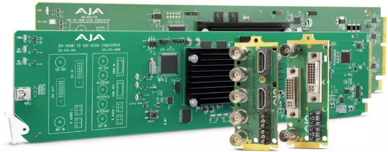
natural_image
Green printed circuit board with various electronic components and connectors, no visible text or symbols on the main subject.Installation and Operation Guide
Trademarks
AJA^® and Because it matters. are registered trademarks of AJA Video Systems, Inc. for use with most AJA products. AJA^TM is a trademark of AJA Video Systems, Inc. for use with recorder, router, software and camera products. Because it matters. is a trademark of AJA Video Systems, Inc. for use with camera products.
Corvid Ultra ^® , Io ^® , Ki Pro ^® , KONA ^® , KUMO ^® , ROI ^® and T-Tap ^® are registered trademarks of AJA Video Systems, Inc.
AJA Control Room™, KiStor™, Science of the Beautiful™, TruScale™, V2Analog™ and V2Digital™ are trademarks of AJA Video Systems, Inc.
All other trademarks are the property of their respective owners.
Copyright
Copyright © 2021 AJA Video Systems, Inc. All rights reserved. All information in this manual is subject to change without notice. No part of the document may be reproduced or transmitted in any form, or by any means, electronic or mechanical, including photocopying or recording, without the express written permission of AJA Video Systems, Inc.
Contacting AJA Support
When calling for support, have all information at hand prior to calling. To contact AJA for sales or support, use any of the following methods:
Telephone +1.530.271.3190
FAX +1.530.271.3140
Web https://www.aja.com
Support Email support@aja.com
Sales Email sales@aja.com
Contents
Notices 2
Trademarks 2
Copyright 2
Contacting AJA Support 2
Chapter 1 – Introduction .....5
Overview....5
Video Processing 5
Audio Handling 6
HDCP Protection 6
Features....6
Pixel Clock Rate 7
OG-ROI Processing Capabilities. 7
Simplified Block Diagram 8
openGear and AJA. 8
I/O Connections 8
All ROI Models....8
OG-ROI-DVI Connectors 9
OG-ROI-HDMI 9
OG-ROI-SDI. 10
Signal Indicators 11
Dashboard Control System 13
Parts List 13
Installation.... 13
Summary 13
Unpacking 13
Rear OG-ROI Series Card Installation. 13
Front OG-ROI Series Card Installation 14
Cabling 16
Typical ROI Configurations. 17
Chapter 2 – Operation....20
Using the Dashboard Control System. 20
Requirements 20
Control Interface Basic Components 20
Input Screen. 22
Click and Drag Options 24
EDID Screen 24
Output Screen 26
About the Rotation, Flip, and Frame Delay Controls. 28
Output 2 Screen 31
HDMI Screen (OG-ROI-SDI) 32
Monitor Matrix Screen 33
Genlock Screen. 34
Audio Screen (OG-ROI-HDMI/DVI). 35
Audio Screen (OG-ROI-SDI) 36
Setup Screen 37
Upload Screen. 38
Rebooting 39
Appendix A – Specifications ..... 41
OG-ROI-DVI Tech Specs 41
OG-ROI-HDMI Tech Specs 42
OG-ROI-SDI Tech Specs. 44
Appendix B – Safety and Compliance ..... 46
Warranty and Liability Information....56
Limited Warranty on Hardware. 56
Limitation of Liability 56
Governing Law and Language; Your Rights. 56
Index. 58
Chapter 1 – Introduction
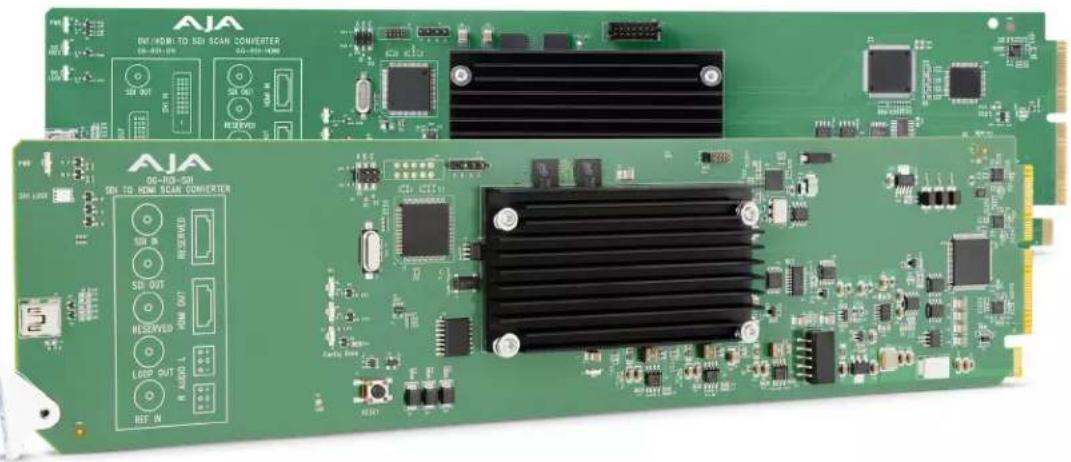
natural_image
Green printed circuit board with various electronic components and connectors (no readable text or symbols)Overview
AJA's OG-ROI family of scalers/scan converters provide exceptionally high quality conversion of computer and video signals in an openGear form factor. The OG-ROI models offer Region of Interest (ROI) support allowing DVI, HDMI and SDI input signals to be scaled and converted to an SDI output. The OG-ROI-SDI model also provides a scaled HDMI output. With incredible image scaling, extensive aspect ratio and frame rate conversion, OG-ROI fulfills the need to scale computer and video to a desired resolution, all in realtime.
The three models of OG-ROI openGear cards available are:
Designed for use in high-density openGear 2RU frames, including AJA's OG-X-FR 2RU frame, the OG-ROI Series is capable of communicating with Ross Video's Dashboard Control System. Dashboard runs on Windows ^® , macOS ^® , and Linux ^® , providing convenient, industry-standard configuration, monitoring and control of the openGear architecture over a PC or local network.
Video Processing
In default mode, the OG-ROI-DVI and OG-ROI-HDMI models automatically detect the input signal format and convert it to the SDI (and HDMI, for the OG-ROI-SDI) output video format. Their respective DVI and HDMI outputs pass the signal through without any processing, maintaining the incoming signal aspect ratio.
For the OG-ROI-SDI, the incoming signal is passed to the SDI Loop Through Output, without any processing, maintaining the incoming signal aspect ratio. The processed signal goes to both the HDMI output and the SDI output.
In Auto mode, if there is a difference in aspect ratio relative to the input and output format, the unused area is filled with a user-configurable matte color. For example, a 720p input will matte with a 625i output and vice versa, due to their different aspect ratios of 16:9 and 4:3, respectively. However, a 720p input will not matte with a 1080p output as they both have a 16:9 aspect ratio.
Audio Handling
OG-ROI-DVI, OG-ROI-HDMI
Analog audio from the host can be input via 3-pin analog audio connectors and mapped to the embedded SDI output stream. Alternatively, when an HDMI input signal is present, the HDMI input's embedded audio can be mapped to the embedded SDI output stream.
The OG-ROI-DVI model can receive both DVI and HDMI protocol input, and accepts audio if it is embedded in an HDMI signal. However, the DVI protocol does not carry audio, so if the OG-ROI-DVI is receiving DVI input, only analog audio can be embedded to the output.
OG-ROI-SDI
Digital audio embedded in the SDI input is carried through to both the SDI output and the HDMI output. Analog audio can be output through the 3-pin analog audio connectors (2 channels). Digital audio can be embedded through the SDI output as 24-bit, 8 channel, and/or through the HDMI output as 24-bit, 2 channel or 8 channel.
HDCP Protection
The OG-ROI honors HDCP, and will not allow an HDCP link. If the input content is HDCP protected, no source video will be displayed on the OG-ROI's DVI pass-through connector, or on the OG-ROI's SDI output.
Features
OG-ROI-DVI
- Converts DVI input to 3G, HD, or SD-SDI output
OG-ROI-HDMI
- Converts HDMI input to 3G, HD, or SD-SDI output
OG-ROI-SDI
- Extracts 3G-SDI input and outputs to 3G, HD, SD-SDI and/or HDMI
All OG-ROI Models
-
openGear compatible card
• EDID Emulation (OG-ROI-HDMI and OG-ROI-DVI)
• 3G-SDI output (and HDMI 1.4 output for OG-ROI-SDI)
• Supports SD, HD, and 3G formats (see Tech Specs for complete list)
• Region of Interest scaling -
Up, down, cross-conversion
- Aspect ratio conversion
• Frame rate conversion
• Image H/V flip and 90 degree rotation - Conversion between Deinterlaced and Progressive signals
- Loss of input management: Black, or Mute
• Supports 8-channels of embedded audio
• Genlock: Reference Input, HDMI/DVI/SDI Input, or Free Run - Remote Ethernet configuration through Ross DashBoard software
• Power: 8 watts (OG-ROI-HDMI, OG-ROI-DVI)
• Power: 7 watts (OG-ROI-SDI) - Hot-swappable
- Rear I/O card included
- Two slots required for each card
- Compatible with OG-X-FR, OG-3-FR, and DFR-8321 openGear frames
- Five year warranty
Pixel rates are limited to a 165 MHz maximum rate.
Pixel Clock Rate
The source video pixel clock is a combination of the video resolution and its vertical rate. Some sources can generate pixel clock rates that exceed the capabilities of the OG-ROI-DVI and OG-ROI-HDMI converters. It may not be obvious what the resulting pixel clock will be for a particular resolution or vertical rate.
NOTE: This topic does not apply to the OG-ROI-SDI since it accepts only SMPTE SDI rates on the input.
For example, when a downstream sink device is connected to the OG-ROI output monitor connector, the source and sink could potentially negotiate a display format (using EDID) that is beyond the capability of OG-ROI's video processing circuitry.
When this error occurs, an "Exceeds max rate" yellow alarm message will be displayed on the Dashboard user interface, and the OG-ROI will generate a full screen red matte on the SDI output. A downstream DVI/HDMI/SDI monitor will still display the incoming video.
Possible solutions include:
- Disconnect the downstream device (for example, a computer monitor) from the OG-ROI. Once disconnected, OG-ROI will negotiate directly with the source to generate a video resolution that is within the OG-ROI's processing capability.
- Reconfigure the source signal to a resolution that OG-ROI supports.
OG-ROI Processing Capabilities
The OG-ROI models utilize a powerful scaling processor, however, some specific combinations of input and output OG-ROI selections, de-interlacing, and 180° rotations or flips can exceed the processing capacity of the OG-ROI cards.
In these cases, a "Processing Limit Exceeded" red error message is displayed on the Dashboard user interface, and the OG-ROI will automatically turn off certain features in order to process the picture. These features that have been turned off will be reported and will be in red. For an example, see "Processing Limit Exceeded" on page 30.
Possible solutions include:
- Reduce the size of the Region of Interest selections; input OG-ROI, output OG-ROI, or a combination of both.
- Turn off 180 degree rotation and/or H and V flips, or frame delay.
- Use a progressive rather than interlace input signal.
Simplified Block Diagram
Figure 1. OG-ROI Converter/Scaler, Simplified Block Diagram
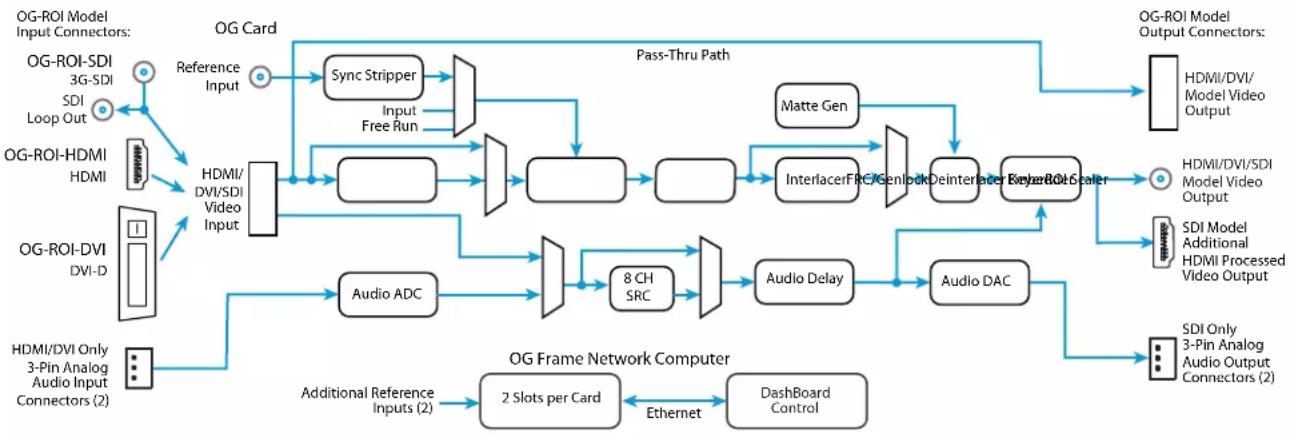
flowchart
graph TD
    A["OG-ROI Model Input Connectors"] --> B["OG-ROI-SDI 3G-SDI"]
    A --> C["OG-ROI-HDMI HDMI"]
    A --> D["OG-ROI-DVI DVI-D"]
    A --> E["HDMI/DVI Only 3-Pin Analog Audio Input Connectors (2)"]

    B --> F["OG Card"]
    C --> G["HDMI/ DVI/SDI Video Input"]
    D --> H["Audio ADC"]
    E --> I["OG Frame Network Computer"]

    F --> J["Sync Stripper"]
    F --> K["Input Free Run"]
    G --> L["InterlacerFRC/Genlock"]
    G --> M["Deinterlacer"]
    G --> N["EngineR0-Scaler"]
    H --> O["8 CH SRC"]
    I --> P["Audio Delay"]
    I --> Q["Audio DAC"]

    J --> R["Pass-Thru Path"]
    K --> R
    L --> R
    M --> R
    N --> R

    S["OG-ROI Model Output Connectors"] --> T["HDMI/DVI/Model Video Output"]
    S --> U["SDI Model Additional HDMI Processed Video Output"]
    S --> V["SDI Only 3-Pin Analog Audio Output Connectors (2)"]

    W["Additional Reference Inputs (2)"] --> X["2 Slots per Card"]
    X --> Y["Dashboard Control"]

    Z["Reference Input"] --> F
    AA["Matte Gen"] --> R
openGear and AJA
openGear is an open-architecture, modular frame system designed by Ross Video and supported by a diverse range of terminal equipment manufacturers, including AJA. Ross Video manufactures the frames, power supplies and network cards for openGear. AJA is a reseller of the openGear frames.
AJA Video is a leading manufacturer of video interface technologies, converters, digital video recording solutions and professional cameras, bringing high-quality, cost-effective products to the professional, broadcast and post-production markets. AJA products, including openGear cards, are designed and manufactured at our facilities in Grass Valley, California.
I/O Connections
All ROI Models
SDI Video Output
The SDI output BNC delivers the processed output signal which has scaling, region of interest, converted raster, converted frame rate, and embedded audio.
Reference Video Input
The Reference BNC accepts an Output timing reference signal. The reference can be SD Blackburst or HD tri-level sync.
Figure 2. I/O Connections for the OG-ROI-DVI Converter/Scaler
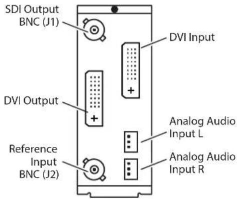
DVI Input
Connects to your Computer or single-link source device.
DVI Output
This is a pass-through unprocessed DVI output for use on a second computer monitor.
NOTE: To connect an HDMI video signal to a DVI connector, or vice versa, you can use a passive HDMI-to-DVI adapter, or use a cable adapter with an HDMI connector on one end and a DVI connector on the other (user-supplied).
Analog Audio Input
Two 3-pin analog audio connectors accept two channels of analog audio which can be embedded into the SDI output as determined by the audio configuration set using Dashboard.
OG-ROI-HDMI
Figure 3. I/O Connections for the OG-ROI-HDMI Converter/Scaler
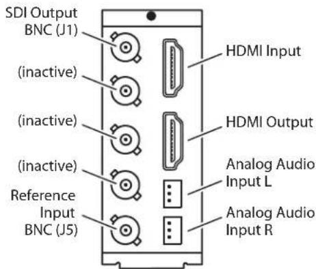
NOTE: Because the same rear module is used for both the OG-ROI-HDMI and OG-ROI-SDI, the functionality of the connectors is determined not by the rear module, but by the OG card it is attached to.
HDMI Input
Connects to your computer or single-link source device.
HDMI Output
This is a pass-through unprocessed HDMI output for use on a second computer monitor.
NOTE: To connect an HDMI video signal to a DVI connector, or vice versa, you can use a passive HDMI-to-DVI adapter, or use a cable adapter with an HDMI connector on one end and a DVI connector on the other (user-supplied).
Analog Audio Input
Two 3-pin analog audio connectors accept two channels of analog audio which can be embedded into the SDI output as determined by the audio configuration set using Dashboard.
OG-ROI-SDI
Figure 4. I/O Connections for the OG-ROI-SDI Converter/Scaler
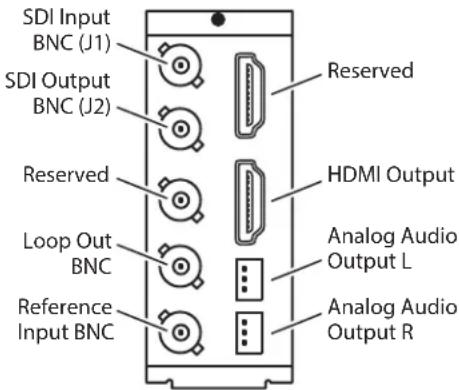
NOTE: Because the same rear module is used for both the OG-ROI-HDMI and OG-ROI-SDI, the functionality of the connectors is determined not by the rear module, but by the OG card it is attached to.
SDI Video Input
Connects to a single-link SDI source device.
SDI Loop Output
The SDI Loop Output provides a copy of the SDI Input signal. It is not processed.
HDMI Output
This is a copy of the processed SDI output signal for driving a display or device with an HDMI input.
Analog Audio Output
Two 3-pin analog audio connectors output two channels of analog audio disembedded from the incoming SDI, as determined by the audio configuration set using Dashboard.
Signal Indicators
OG-ROI-DVI/HDMI Card
Located at the upper front area of the OG-ROI-DVI/HDMI card, the LEDs shown in Figure 5 below indicate the status of the card's power, signal presence and signal lock.
Figure 5. LED lights on OG-ROI-DVI/HDMI card
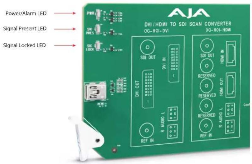
Power LED
The Power LED indicates the state of the card as displayed in Dashboard. It can be green, yellow or red.
- Green: no Dashboard card state alarm is present.
- Yellow: a yellow Dashboard card state alarm is present. See Dashboard for more information.
- Red: a red Dashboard card state alarm is present. See Dashboard for more information.
Signal Present LED
The Signal Present LED can be green or off.
- Green: incoming signal has been identified and acquired.
- Off: no signal is detected.
Signal Lock LED
The Signal Locked LED can be green or off.
- Green: incoming signal is locked. Note that in DashBoard, the Status tab shows what signal you are locked to (HDMI, Reference Input, or Free Run).
- Off: no reference is present.
Located at the upper front area of the OG-ROI-SDI card, the LEDs shown in Figure 6 below indicate the status of the card's power and signal lock.
Figure 6. LED lights on OG-ROI-SDI card
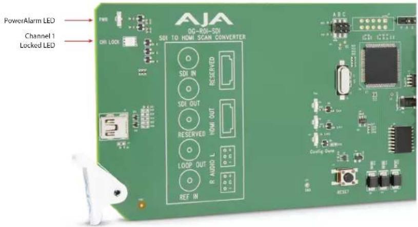
Power LED
The Power LED indicates the state of the card as displayed in Dashboard. It can be green, yellow or red.
- Green: no Dashboard card state alarm is present.
- Yellow: a yellow Dashboard card state alarm is present. See Dashboard for more information.
- Red: a red Dashboard card state alarm is present. See Dashboard for more information.
Signal Lock LED
The Signal Lock LED has four states:
- Off: Not locked to an input signal
• Green: Locked to 270 Mb input signal
• Red: Locked to 1.5Gb input signal - Amber: Locked to 3Gb input signal
Dashboard Control System
IMPORTANT: Dashboard version 8.5.1 or later is required to support the OG-ROI cards.
The Dashboard Control System, created by Ross Video, provides a control interface between Windows, macOS and Linux computers and the cards installed in an openGear frame. Dashboard operates through TCP/IP communication and requires an Ethernet connection between the controlling computer and an openGear frame.
Details for acquiring and using the Dashboard Control System are provided in "Using the Dashboard Control System" on page 20.
Parts List
| Quantity Description | |
| 1 OG-ROI Series Front Card in ESD bag | |
| 1 DVI / HDMI / BNC | Rear Card |
| 2 WECO mating connectors, part number 107654-00 | |
The OG-ROI-HDMI and OG-ROI-SDI use the same rear card.
Installation
Summary
Installing an OG-ROI Series card into an OG-X-FR or OG-3-FR openGear frame consists of the following steps:
- Install the Rear Panel onto the back of the frame corresponding to the slot pair you will be using for the OG-ROI Series card.
- Insert the OG-ROI Series card into the frame in the right (even numbered) slot of the pair.
- Connect the BNC and audio cabling to the Rear Panel.

ESD Susceptibility - Static discharge can cause serious damage to sensitive semiconductor devices. Avoid handling circuit boards in high static environments such as carpeted areas, and when wearing synthetic fiber clothing. Always exercise proper grounding precautions when working on circuit boards and related equipment.
Unpacking
Unpack each openGear product you received from the shipping container and ensure that all items are included. If any items are missing or damaged, contact your sales representative or AJA directly.
Rear OG-ROI Series Card Installation
- Ensure that the frame is properly installed.
- Locate the card frame slot on the rear of the openGear frame into which you wish to install the openGear card.
NOTE: An OG-ROI Series card occupies two slots in the frame.
- Using a Phillips screwdriver, unscrew the top screw from the desired blank rear plate and remove the rear plate.
- Seat the bottom of the Rear Card in the seating slot at the base of the frame back plane.
Figure 7. Rear Card Inserting Into Frame Seating Slot
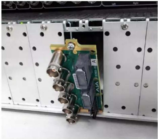
natural_image
Interior view of an electronic device showing a green circuit board with multiple connectors and metallic components, mounted on white panels (no visible text or symbols)- Align the top screw of the Rear Card with the screw hole on the top edge of the frame back plane.
- Ensure the Rear Card aligns with the desired card slot before tightening the screw.
- Using a Phillips screwdriver, fasten the Rear Card to the frame back plane. Do not over tighten.
Figure 8. Rear Card Inserted Into Frame Seating Slot
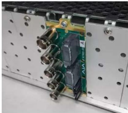
natural_image
Close-up of an electronic device showing internal components including a green circuit board and metallic connectors (no visible text or symbols)- Ensure proper frame cooling and ventilation by having all rear frame slots covered with rear modules or blank metal plates if plates are not pre-installed.
Front OG-ROI Series Card Installation
- Open the openGear frame door as follows:
A. Gently pull the side door tabs towards the center of the door, releasing the door from the frame.
B. Using both hands, pull the door towards you. The door extender arms prevent the door from falling.
-
Locate the Rear Card you installed as described above. The interior slot number is dependent on the slot combinations into which you installed the Rear Card. This allows adequate spacing to avoid damaging the card, the cards installed in the neighboring slots, or both.
-
Hold the card by the edges and carefully align the card edges with the rails inside the frame. The slots are numbered starting from the left-most slot when facing the frame front.
IMPORTANT: OG-ROI Series cards are installed into the right (even numbered) slot of the pair in order to connect with the rear panel.
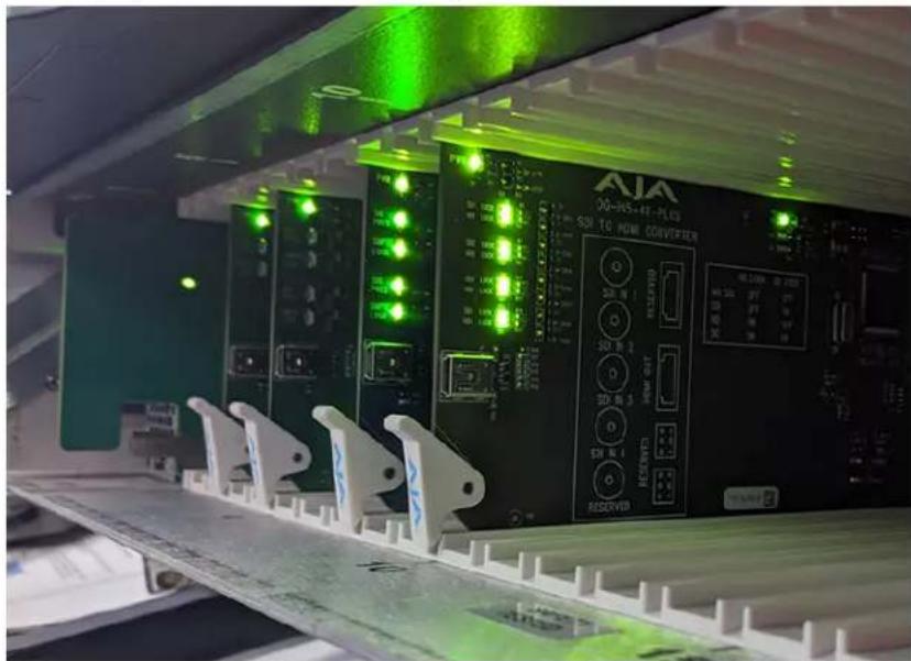
- Fully insert the card into the frame until the card is properly seated in the Rear Card. There are two stages to inserting the card:
A. After you feel the card's first click, its position in the frame will resemble the photograph below in Figure 9.
B. Next, press against the white plastic tab again until you feel the second click. The card's position will resemble the photograph below in Figure 10.
WARNING: Some cards require more pressure than others to be fully inserted. Make sure that the plastic tab at the bottom of the front edge of the card is completely upright. If it is tilting forward, the card is not yet fully inserted.
Figure 9. The card on the right is already fully inserted. The card to its left (second from the right) is not yet fully inserted, as indicated by the white plastic tab tilting forward.
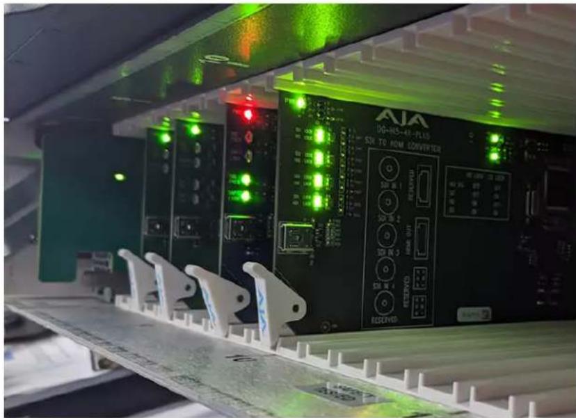
Figure 10. The white plastic tab for the card second from the right is now upright. All cards are shown fully inserted.
- Close the frame door as follows:
A. Slide the door into the frame.
B. Pull and release the door tabs to ensure the frame door is securely locked to the frame.
Cabling
Refer to "I/O Connections" on page 8 to identify the input and output signal connectors.
Two WECO audio mating connectors are included with each OG-ROI Series card.
- Insert connecting audio wires into their corresponding holes from the rear (Figure 11).
Figure 11. Rear view of the WECO mating audio connector
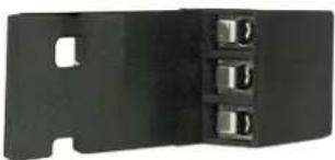
natural_image
Black metal electrical connector with three slots and a slot on the side (no text or symbols visible)- Tighten the screws on the other side of the audio mating connector (Figure 12).
Figure 12. Front view of the WECO mating audio connector showing the tightening screws
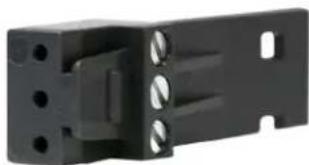
natural_image
Close-up of a black plastic mechanical bracket with mounting holes and internal cavities (no text or symbols visible)-
After you have secured the wiring for each WECO mating audio connector, connect them to the audio output connectors on the rear panel of the OG-ROI Series card.
-
Add tie wraps around the audio connectors for strain relief.
Typical ROI Configurations
Two typical configurations for using the OG-ROI for scaling of desktop region-of-interest computer-sourced video are illustrated in the following two figures. In these configurations, the pass-through monitor is used to view the subject desktop video.
Figure 13. OG-ROI with Laptop Computer, System Interconnect Diagram
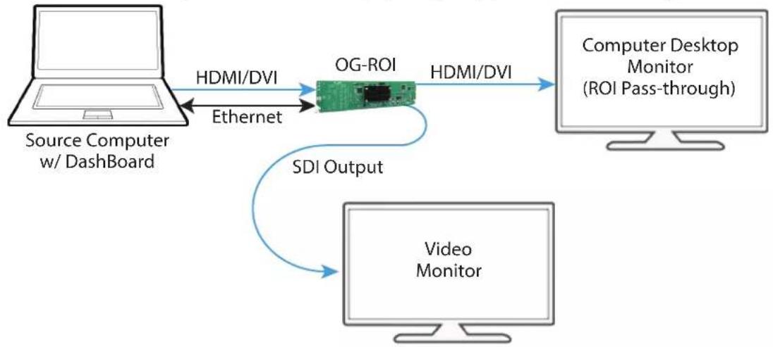
flowchart
graph LR
    A["Source Computer w/ Dashboard"] -->|HDMI/DVI Ethernet| B["OG-ROI"]
    B -->|HDMI/DVI| C["Computer Desktop Monitor (ROI Pass-through)"]
    B -->|SDI Output| D["Video Monitor"]
Figure 14. OG-ROI with Tower Computer & Two Monitors, System Interconnect Diagram
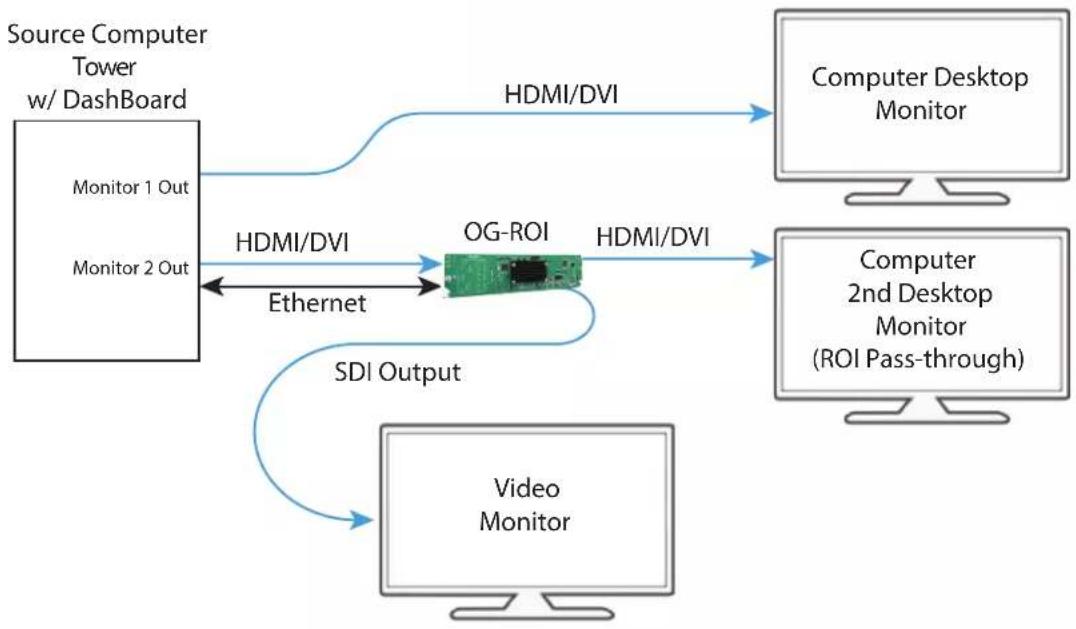
flowchart
graph TD
    A["Source Computer Tower w/ Dashboard"] -->|HDMI/DVI| B["Computer Desktop Monitor"]
    A -->|HDMI/DVI| C["OG-ROI"]
    C -->|HDMI/DVI| D["Computer 2nd Desktop Monitor (ROI Pass-through)"]
    C -->|SDI Output| E["Video Monitor"]
    A -->|Monitor 1 Out| F["Internet"]
    A -->|Monitor 2 Out| G["Internet"]
    F <-->|Ethernet| C
    G <-->|Ethernet| C
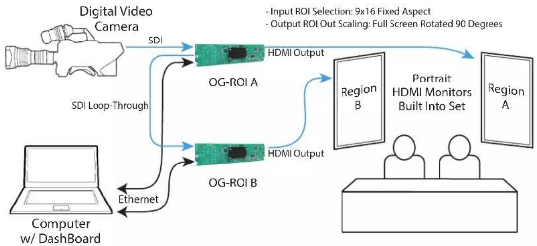
A third example (Figure 15) illustrates use of the OG-ROI Rotation feature to send selected areas of a SDI signal to portrait mounted on-set monitors at full resolution. Each monitor uses one OG-ROI converter, accomplishing the task at a much lower cost than dedicating DVE channels for rotation and resizing.
Figure 15. OG-ROI Rotation with Portrait Mounted On-Set Monitors
flowchart
graph TD
    A["Digital Video Camera"] -->|SDI| B["OG-ROI A"]
    A -->|SDI Loop-Through| C["OG-ROI B"]
    B -->|HDMI Output| D["Region B"]
    C -->|HDMI Output| D
    E["Computer w/ Dashboard"] -->|Ethernet| B
    F["Input ROI Selection: 9x16 Fixed Aspect"] --> B
    G["Output ROI Out Scaling: Full Screen Rotated 90 Degrees"] --> D
    H["Portfolio HDMI Monitors Built Into Set"] --> D
    I["Region A"] --> D
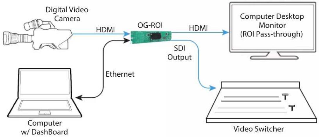
A fourth example below illustrates sending HDMI digital video from a camera to an OG-ROI to allow region of interest video input to a video switcher.
Figure 16. OG-ROI-HDMI with Video Camera to Switcher Interconnect Diagram
flowchart
graph LR
    A["Digital Video Camera"] -->|HDMI| B["OG-ROI"]
    B -->|HDMI| C["Computer Desktop Monitor (ROI Pass-through)"]
    D["Computer w/ Dashboard"] -->|Ethernet| B
    B -->|SDI Output| E["Video Switcher"]
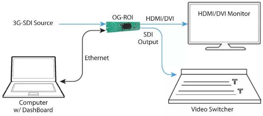
In a parallel configuration as Figure 16, Figure 17 below shows a basic configuration of the OG-ROI-SDI being used to send a 3G-SDI digital video signal to allow region of interest video input to a video switcher. You can use methods for adjusting the region of interest selection described in the section for the "Input Screen" on page 22 with the processed 3G-SDI output signal feeding a monitor.
Figure 17. OG-ROI-SDI with SDI Source to Switcher Interconnect Diagram
flowchart
graph TD
    A["Computer w/ Dashboard"] -->|Ethernet| B["OG-ROI"]
    B -->|HDMI/DVI| C["HDMI/DVI Monitor"]
    B -->|SDI Output| D["Video Switcher"]
    D -->|Ethernet| A
Chapter 2 – Operation
IMPORTANT: Once you have configured the OG-ROI card using Dashboard, and as long as the input format remains the same, the settings will persist when the frame is disconnected from a controlling computer (in stand-alone mode). If you anticipate that the input format may change, and if the current configuration settings wouldn't make sense for a different input format, you can enable Auto Bypass Mode (Auto Bypass Mode checkbox is selected from the Input tab). When enabled, Auto Bypass Mode forces the OG-ROI card to use Auto in all applicable settings when the input format changes. When the original input format is re-connected, the OG-ROI will exit Auto Bypass Mode and restore all previously configured settings for that format.
Using the Dashboard Control System
The Dashboard Control System, created by Ross Video, is available as a free download from the openGear Dashboard Software Download webpage:
https://www.opengear.tv/frame-and-control/control-system/download/
Ross Video offers comprehensive documentation that covers the extensive capabilities of the Dashboard Control System:
https://www.rossvideo.com/support/product-documentation/dashboard/
This manual addresses only those essential aspects of the Dashboard Control System needed to control the OG-ROI Series cards.
Requirements
The Dashboard Control System requires the following components:
- openGear frame with a Frame Controller card
- Ethernet connection between the controlling computer and the openGear frame
NOTE: The openGear frame ships from AJA with the MFC-8322-S Frame Controller card for controlling the new AJA Dashboard cards. The openGear frame also supports the MFC-0G3-N Advanced Networking Frame Controller card, which can be used to control compatible OG cards.
IMPORTANT: Dashboard version 8.5.1 or later is required to support the OG-ROI cards.
Dashboard automatically discovers openGear and Dashboard Connect devices, such as openGear frames and cards that are present and accessible on your network.
Control Interface Basic Components
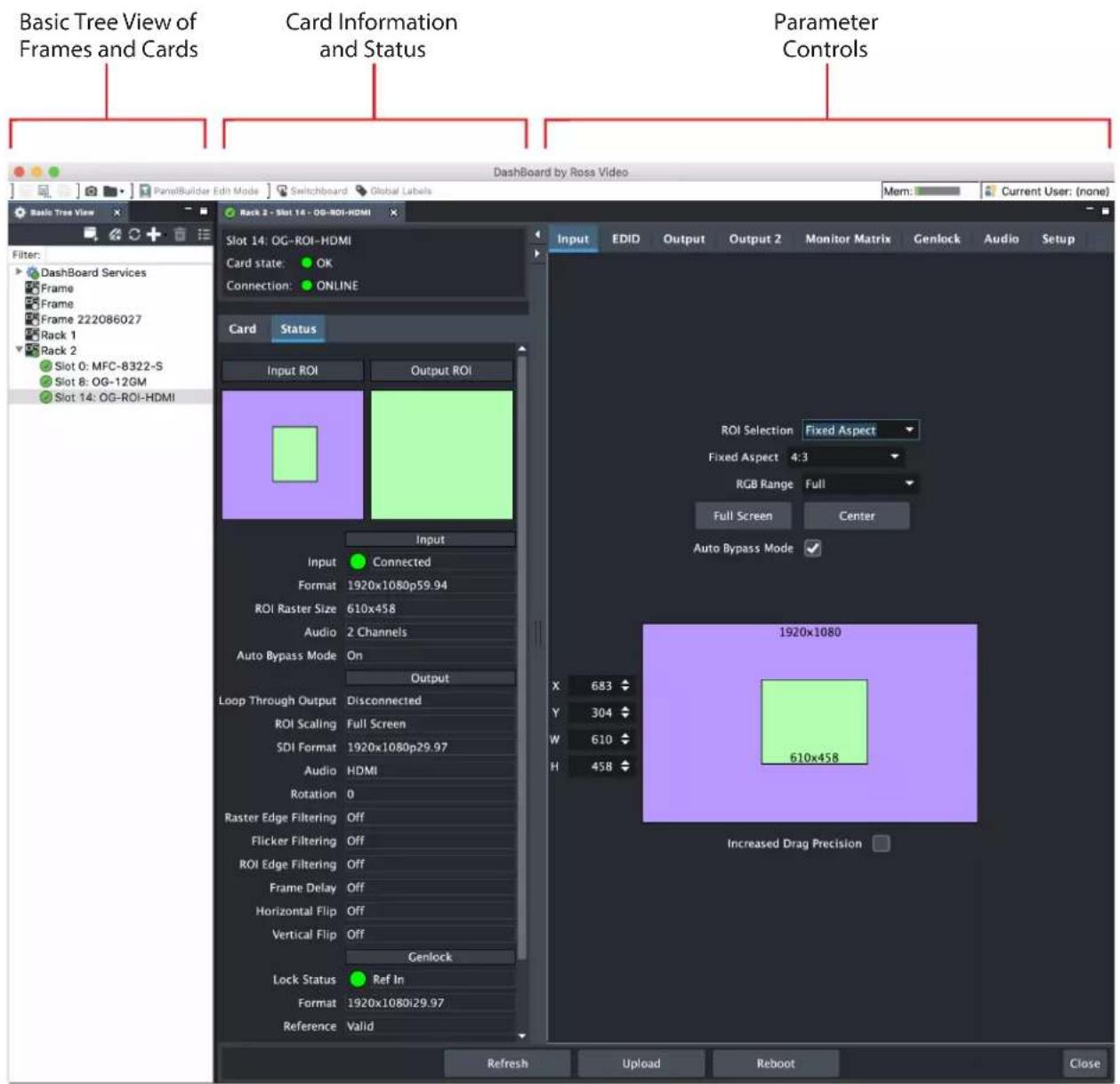
The basic components of the Dashboard Control System user interface consist of the basic tree view of frames and cards, the card information and status panel, and the parameter controls panel. These elements are shown below in Figure 18 on page 21
The basic tree view of frames and cards shows the frames and cards that are discoverable by Dashboard on your network.
The card information and status panel, shown in the middle panel, display the basic status of the card currently selected in Dashboard.
The parameter controls panel shows the tabs and parameters that the selected card has available for configuration and control.
Figure 18. Main Sections of the Dashboard User Interface
Input Screen
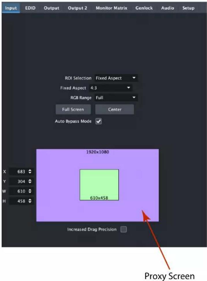
Click on the Input tab to view and make changes to the converter's input region-of-interest settings.
An input signal is required before the Input menu configuration controls are available. When no input signal is present, the OG-ROI unit grays out the Input menu controls.
The Proxy Screen shows the current region of interest setting in green with the selection pixel size at the bottom and the input pixel size at the top. Various controls are also available on the left.
NOTE: The adjustments made on the green proxy screens are live and can be viewed on the SDI output.
NOTE: Portions of this screen are grayed out if no input signal is present.
ROI Selection
Using this pulldown menu you can choose a selection mode:
Auto - Selects the entire signal detected at the input to the ROI (default setting). Scales the input region-of-interest as large as possible to fit into the SDI output region while maintaining the incoming aspect ratio. Matte may result if the input's aspect ratio does not match the SDI out aspect ratio.
NOTE: Auto selections in the Input screen and the Output screen are linked. Selecting Auto from one screen will also select Auto in the other screen.
Variable - Allows user-adjustable selection of all or a portion of the input signal. When you select Variable as the selection type, you can choose the region-of-interest selection in three ways with no constraints:
- Use the X,Y coordinates and W,H (width, height) size fields. Within these fields, you can enter values (if they are valid) or use your keyboard arrow keys to increment one pixel/line at a time for fine adjustment.
- If configuring a multiple monitor matrix, you can use the Monitor Matrix screen to select the ROI and, when applied, will fill the X, Y, W, and H fields with the correct values. See "Monitor Matrix Screen" on page 33.
- Drag the edges of the image representation (green proxy screen) at the right of the selection pane. See "Click and Drag Options" on page 24.
Fixed Aspect - Opens a ROI Fixed Aspect drop-down menu allowing fixed aspect input region-of-interest selection. In this mode, the size of the selected region-of-interest can change but the aspect ratio is held constant:
• 4:3 (SD aspect ratio)
• 16:9 (HD aspect ratio)
• 3:4 (useful for presentation on vertically oriented monitors)
• 9:16 (useful for presentation on vertically oriented monitors)
NOTE: Pixel aspect ratio (PAR) is accounted for in fixed aspect mode. The storage aspect ratio will change based on the input's PAR to achieve a display aspect ratio equivalent to your configured settings.
Fixed Size - Opens a ROI Fixed Size drop-down menu allowing fixed size input region-of-interest selection. In this mode, the region-of-interest selection can change position on the input screen but the size cannot be changed. These settings allow you to easily select standard video sizes for region-of-interest.
SDI Out - Forces the region-of-interest to have the same aspect ratio as the current SDI Out Format setting.
RGB Range Menu (not applicable to OG-ROI-SDI)
The RGB Range pulldown menu allows you to select either Full range (0-1023) or SMPTE range (typically 64-940) for RGB color input.
Full Screen Button
Click the Full Screen button to set the region-of-interest to the full input raster size.
Center Button
If you choose anything other than a full-sized image (Auto) in the ROI Select menu, you will have complete control of where the region of interest selection is placed. To quickly and precisely center the region-of-interest, click the Center button.
Auto Bypass Mode
Once you have configured the OG-ROI card using Dashboard, and as long as the input format remains the same, the settings will persist when the frame is disconnected from a controlling computer (in stand-alone mode).
If you anticipate that the input format may change, and if the current configuration settings wouldn't make sense for a different input format, you can enable Auto Bypass Mode (Auto Bypass Mode checkbox is selected from the Input tab). When enabled, Auto Bypass Mode forces the OG-ROI card to use Auto in all applicable settings when the input format changes.
When the original input format is re-connected, the OG-ROI will exit Auto Bypass Mode and restore all previously configured settings for that format.
Click and Drag Options
When using the drag method for region-of-interest placement or resizing, you can use the Increased Drag Precision functionality for precise adjustments.
Increased Drag Precision
For more control, select the Increased Drag Precision checkbox. While dragging the image, you will notice that the selection changes in a more gradual pixel-by-pixel manner regardless of your drag speed.
Arrow Keys
You can use the keyboard arrows to increment size and placement of a variable region-of-interest selection one pixel at a time in X, Y, H, W fields. (The up/down arrow keys can also be used to step through some menu selections.)
EDID Screen
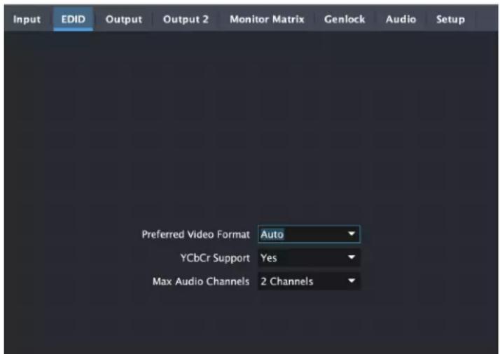
EDID (Extended Display Identification Data) is used to find the highest signal resolution that is compatible with both the source and the destination (sink) devices. When an HDMI source device is initially connected to the ROI MiniConverter, the ROI sends its EDID information to that source. The source uses this information to decide what format to send.
NOTE: The OG-ROI-SDI does not have an EDID tab screen because it does not support EDID.
NOTE: For OG-ROI-DVI and OG-ROI-HDMI devices, when a sink device is connected, its EDID is passed through to the source device and the settings on the EDID tab are not used. If no sink device is connected, the settings on the EDID tab are used.
Preferred Video Format
The OG-ROI's default EDID selection is Auto but it can be configured by the user to any of the following formats and frame rates:
• Auto
- 1280x720p50
- 1280x720p60
• 1920x1080i25
- 1920x1080i30
• 1920x1080p50
• 1920x1080p60
YCbCr Support
This parameter determines whether the OG-ROI will signal to its HDMI source that the OG-ROI will support (Yes) or will not support (No) YCbCr input formats.
NOTE: RGB formats are always supported by default in an HDMI sink.
Max Audio Channels
Selects the number of audio channels to be used from the signal source. Choose from:
- 2 Channels
- 8 Channels
Output Screen
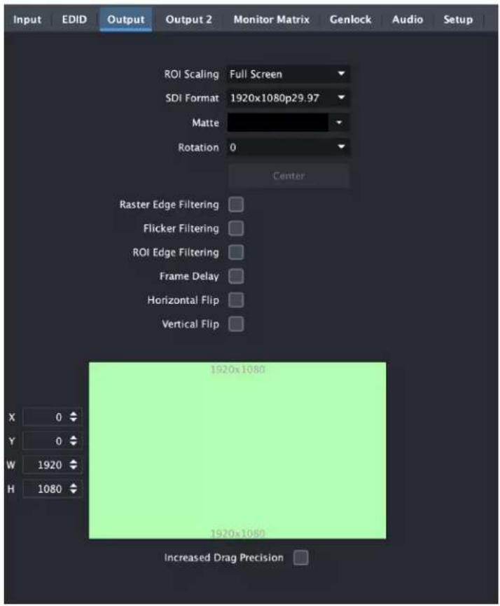
Click on the Output Tab to adjust the following parameters.
NOTE: Portions of this screen are grayed out if no input signal is present.
NOTE: Some sources can generate pixel clock rates that exceed the capabilities of the ROI. If the incoming video's pixel clock rate is too high, the ROI converter will generate a full screen red matte on the SDI output to indicate this error condition. Dashboard will also display an "Exceeds max rate" error message. A downstream HDMI/DVI/SDI monitor will still display the incoming video. See "Pixel Clock Rate" on page 7 and "OG-ROI Processing Capabilities" on page 7 for potential solutions.
ROI Out Scaling
Use the ROI Out Scaling pulldown menu to select one of the following:
Auto - Automatically scales region-of-interest to maximum size with fixed aspect ratio defined by input format (default setting).
NOTE: Auto selections in the Output screen and the Input screen are linked. Selecting Auto from one screen will also select Auto in the other screen.
Fixed Aspect - Matte - Scales region-of-interest to maximum size to fit output region while maintaining aspect ratio. Matting may occur if aspect ratio of input format and output format do not match.
Full Screen - Scales region-of-interest to maximum size to fit output geometry. This may change aspect ratio of the image. No matting will occur.
None - Crop/Matte - No scaling occurs to region-of-interest. It is always centered on the output, and the area displayed is selected using the placement controls in the Input menu.
Variable - Allows user to arbitrarily change position and scaling of region-of-interest as it is placed into the output region.
SDI Output Format
The pulldown menu offers a full range of SDI Video Formats for output. For the complete list, see "Appendix A Specifications" on page 41. The format selection is reported in the Dashboard graphic depicting the SDI Output.
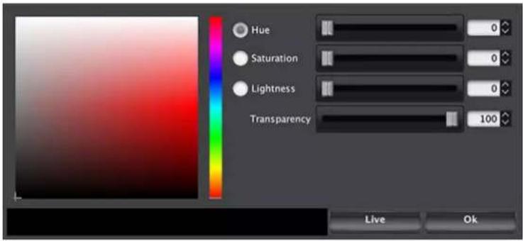
Matte Background
Click the Matte button to pull up the matte color panel that offers various modes of background color selection.
Figure 19. Matte Color Selection Panel
Rotation
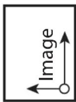
Opens a drop down menu for selecting of a clockwise rotation setting (see Figure 21 on page 29):
- 0^ (no rotation, default setting)
· 90°
· 180°
· 270°
Center Button
After a screen region-of-interest has been defined, click the Center button to quickly center the image.
Raster Edge Filtering Checkbox
You can disable edge filtering with this control. The filtering is applied to the left and right edge pixels of the raster. This is useful if you are using four OG-ROIs to drive a 4K monitor matrix. Disabling edge filtering on all four OG-ROIs can eliminate the vertical line that would occur in that situation. Default setting is On.
Flicker Filtering Checkbox
You can enable flicker filtering with this control. This can be useful where vertical detail (horizontal lines) may strobe with the refresh rate of the display. Flicker filtering can help with interlaced outputs, and when a detailed image is scaled down into a smaller area. Default setting is Off.
ROI Edge Filtering Checkbox
Similar to Raster Edge Filtering above, but the filtering is applied to the left and right sides of the Region of Interest portion of that OG-ROI's output. Default setting is On.
NOTE: The following Rotation, Frame Delay, and Flip controls interact with each other. If the OG-ROI's video processing circuit is unable to perform the processing, the actual Off state of each control is reported in red. See "About the Rotation, Flip, and Frame Delay Controls" on page 28 for more information.
Frame Delay
Turns Frame Delay On or Off. One frame of delay is automatically applied whenever Rotate or Flip is active. The current frame delay state (On or Off) is reported.
NOTE: Turning Frame Delay On can be useful if you are using two ROIs simultaneously, flipping or rotating only one of their outputs. Because a frame delay is always applied to the flipped or rotated output, turning on the other ROI's Frame Delay restores their relative timing.
Horizontal Flip
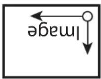
Flips the output horizontally (left to right, and right to left, see Figure 20).
Vertical Flip
Flips the output vertically (top to bottom and bottom to top, see Figure 20).
Figure 20. Flip and Rotation Illustration
Original
(0 Degree, no Flip) 90 Degree Rotation Horizontal Flip Vertical Flip 180 Degree Rotation 270 Degree Rotation
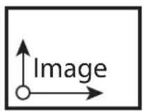
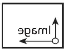
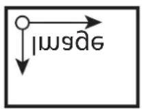
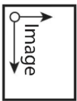
About the Rotation, Flip, and Frame Delay Controls
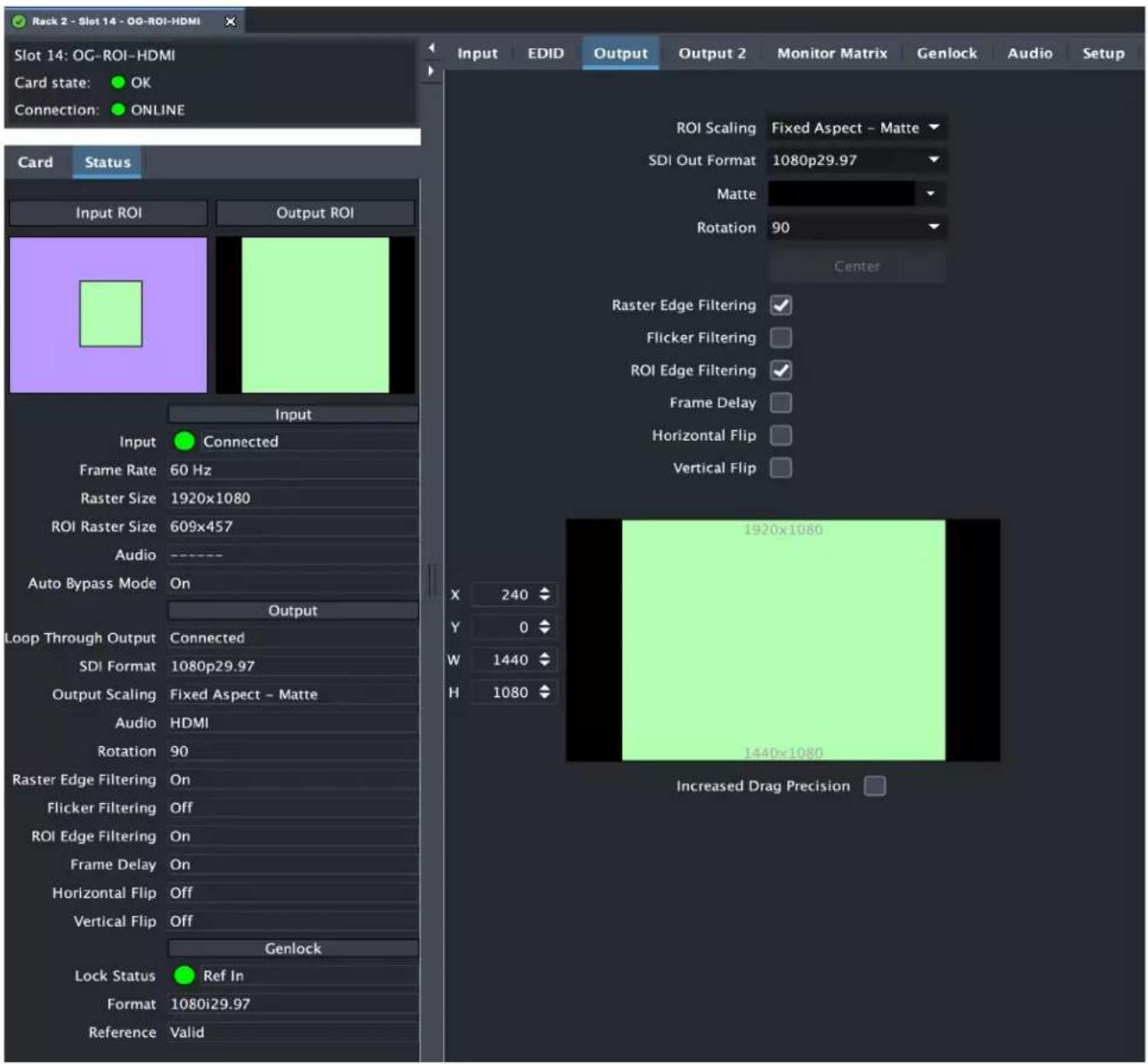
Rotation and Flip image processing requires one frame of video delay. Whenever a rotation or flip occurs a frame delay is automatically applied, and the Frame Delay On status is reported, even if the checkbox isn't selected (see Figure 21).
Figure 21. Frame Delay Automatically On with Rotation even if the checkbox isn't selected
The Rotation, Flip, and Delay controls all report their current statuses. Some specific combinations of input and output selections and 180° rotations or flips involving 1920 x 1080i input video can exceed the processing capacity of the OG-ROI Series. In these unusual cases, a Processing Limit Exceeded yellow warning alarm is displayed on the UI, and the actual current settings for Rotation, Frame Delay, and Flip are reported in red (see Figure 22). Note, however, that parameters using their default values will not be highlighted in red.
Figure 22. Processing Limit Exceeded
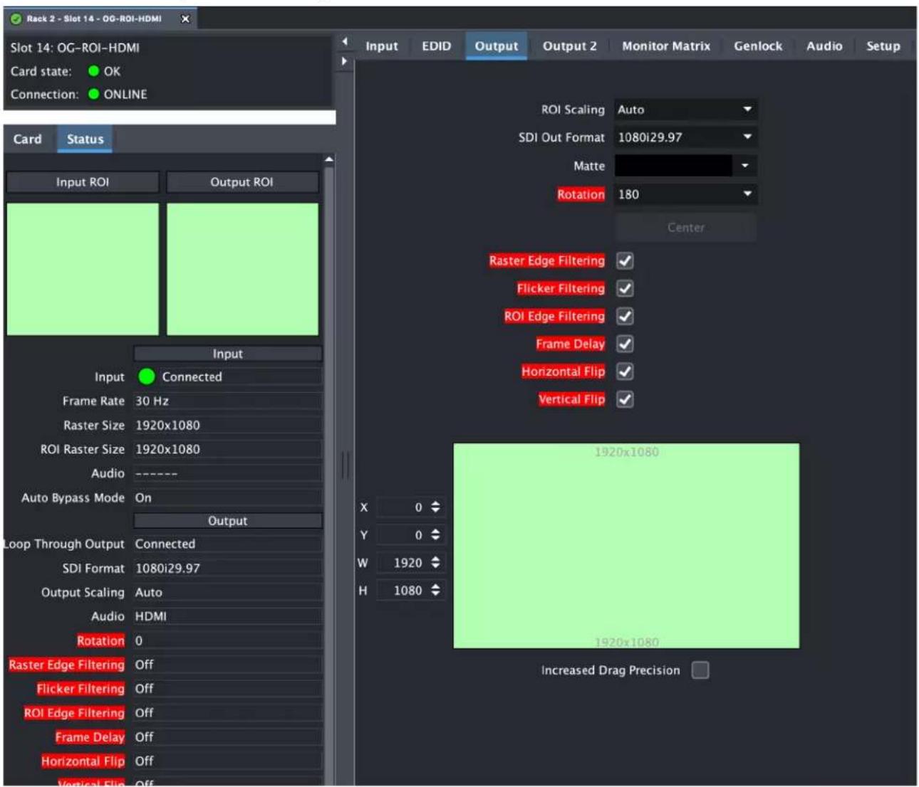
Possible workarounds for this error condition include:
- Select an input source format that is not 1920x1080i.
- Reduce the size of the input or output region of interest.
- Deselect 180^ rotation if on.
Output 2 Screen
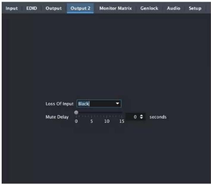
Loss of Input
This parameter lets you control OG-ROI output behavior if the input signal is lost. Selecting Black outputs black video under those circumstances. Selecting Mute will output no-video content (no signal). This can be used in conjunction with a downstream signal loss capability that would not have been triggered with a black signal.
Mute Delay
If Mute is selected from the Loss of Input control above, you can set a time delay (0-15 seconds) for how long the switch to no signal occurs. The last good frame of video is displayed during that delay time.
HDMI Screen (OG-ROI-SDI)
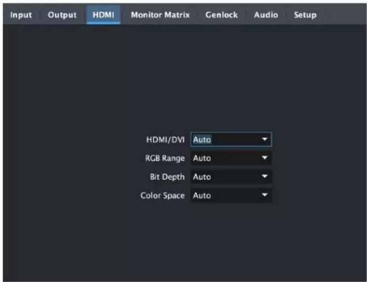
HDMI/DVI
Choose Auto, HDMI, or DVI. When DVI is selected, any audio signals present are not passed. Choosing "Auto" automatically selects the output mode based on the attached device's capabilities.
RGB Range
Choose Auto, SMPTE or Full. Choosing "Auto" automatically selects the RGB output color range setting.
Bit Depth
Choose from Auto, 8-bit, or 10-bit. Choosing "Auto" automatically selects the bit depth based on the input video and the attached device's capabilities.
Color Space
Selects the desired HDMI output video format. Choose from the following:
- Auto - selects the video format based on the input video and the attached device's capabilities.
• 4:2:2 YCbCr
• 4:4:4 RGB
• 4:4:4 YCbCr
Monitor Matrix Screen
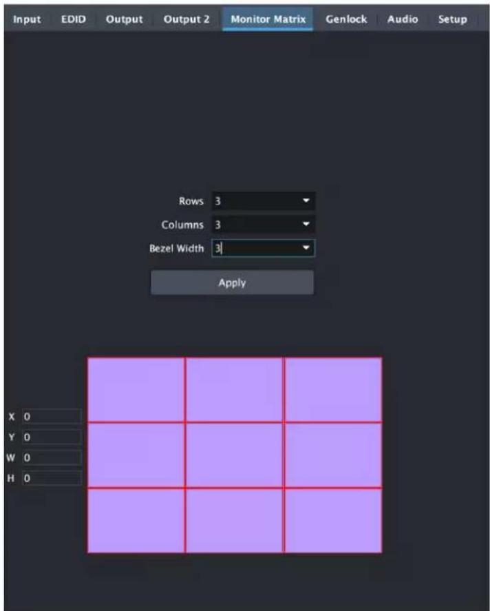
The Monitor Matrix screen offers a calculator that lets you easily define Input Region of Interest dimensions suitable for a multiple monitor matrix display. Typically a monitor matrix is a horizontal and vertical stacking of monitors, with a physical bezel distance separating the edges of the displays from each other. Dedicating one ROI to feed each monitor, and sending the same input video to all the ROIs, makes it possible to display that video so it spans across all the monitors.
Monitor Matrix Representation
A representation of the monitor matrix is shown in the Proxy Screen on the lower right. Clicking selects the area of the monitor at that location in the matrix. When row and column values are entered, a graphical representation of a matrix will be displayed. A default monitor position will be shown as yellow. A new monitor position can be selected by moving the mouse cursor over the desired position and selecting it. The Input Region of Interest position (X,Y) and size (W,H) values will then be automatically calculated. When Apply is clicked, the monitor position rectangle will turn green. When a non-zero Bezel Width is entered, the bezel border around that area is colored red.
Rows
Select the number of rows in the monitor matrix. Select from 1 to 20.
Columns
Select the number of columns in the monitor matrix. Select from 1 to 20.
Bezel Width
Select the bezel width of the display. This width will be used in calculating the Input Region of Interest.
Note that adjoining displays could have a different bezel width and require a different value entered on the ROI driving that monitor.
X, Y, W, H
The currently calculated Input Region of Interest position (X,Y) and size (W,H) are displayed here. These values are grayed out and cannot be adjusted. Once the values are applied, they can be adjusted on the Input tab.
Apply
Click on the Apply button to transfer the current Input Region of Interest dimensions to the Input screen.
Genlock Screen
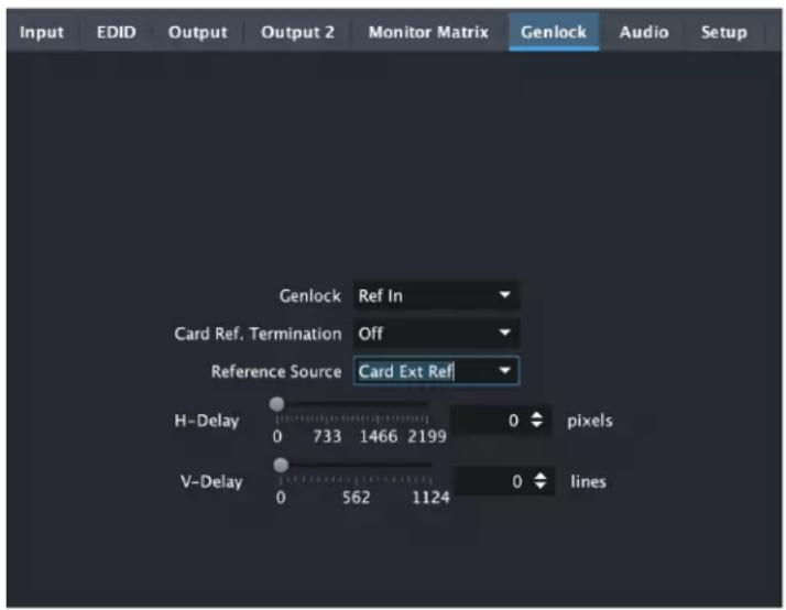
Genlock
The Genlock control offers the following options:
- Auto – use Ref Input if present, then Input signal if valid, then free-run
- HDMI – Lock to the HDMI/DVI Input (if valid video rate)
- Ref In – Lock to the Video Reference input
- Free-run – Lock to internal clock
NOTE: When HDMI is selected, OG-ROI can lock to input formats that have a SMPTE raster and frame rate and are within 50 ppm of the SDI output format.
NOTE: The actual resultant Genlock status is reported in the Status tab.
Card Ref Termination
Whether you turn this control On or Off depends on the configuration of your equipment, and whether or not the incoming reference signal is already terminated. The Ext Ref input impedance is 75 ohms.
For proper operation the input Reference signal must be stable and properly terminated using a 75-ohm terminator on the last piece of downstream equipment to which the Ref Video is connected.
On - Turn on if you have an unterminated incoming reference signal. This will provide 75 Ohm signal termination.
Off - Turn off (default) if the incoming reference signal is already terminated.
Reference Source
Select which source you want to use for Reference. Choose from the following:
Free Run - The OG-ROI Series will lock to its internal clock as the reference source.
Card Ext Ref - The OG-ROI Series will use the incoming reference source connected to the Reference Input BNC on the rear panel of the card.
OG Frame Ref 1 - The OG-ROI Series will use the incoming reference source connected to the openGear frame's Reference 1 Input BNC on the rear of the frame.
OG Frame Ref 2 - The OG-ROI Series will use the incoming reference source connected to the openGear frame's Reference 2 Input BNC on the rear of the frame.
H-Delay and V-Delay
These controls let you adjust H and V delay from the sync input by dragging the slider or entering values in the windows on the right. Horizontal delay is entered in pixels, while Vertical delay is entered in lines.
NOTE: H and V delay adjustments are only available when the SDI Out Format is compatible with the current sync input reference.
Audio Screen (OG-ROI-HDMI/DVI)
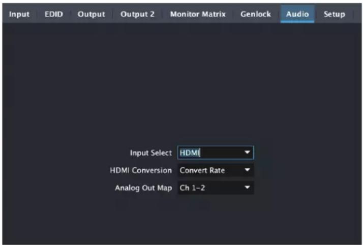
In default mode, the OG-ROI passes up to eight channels of embedded audio from the video input to the video output.
NOTE: The OG-ROI-DVI model can receive both DVI and HDMI protocol input, and accepts audio if it is embedded in an HDMI signal. However, the DVI protocol does not carry audio, so if the ROI-DVI is receiving DVI input, only analog audio can be embedded to the output.
Input Select
Use this control to select which input audio to pass to the SDI output.
- HDMI - This selection passes the HDMI incoming audio to the SDI output (up to 8 channels).
- Analog- This selection passes only the Analog audio input for inclusion into the SDI audio stream. In this case, you can use the Analog Out Map pulldown menu to select the specific channel pair you want to carry the signal.
- Analog + HDMI - This selection causes the Analog audio input to replace one pair of the HDMI audio channels on the SDI output. The analog audio is inserted on the channels defined by the Analog Out Map pulldown.
- None - No audio is output (mute) on the SDI output.
HDMI Conversion
The Convert Rate button enables OG-ROI Series to convert incoming HDMI audio between 32 kHz to 96 kHz to 48 kHz (the SDI native audio standard). If you don't want to convert, choose Pass Through.
Analog Out Map
This control selects which two SDI embedded audio channels receive the incoming L R analog audio when Input Select is set to Analog or Analog + HDMI. Choose from Ch 1-2, Ch 3-4, Ch 5-6, or Ch 7-8.
Audio Screen (OG-ROI-SDI)
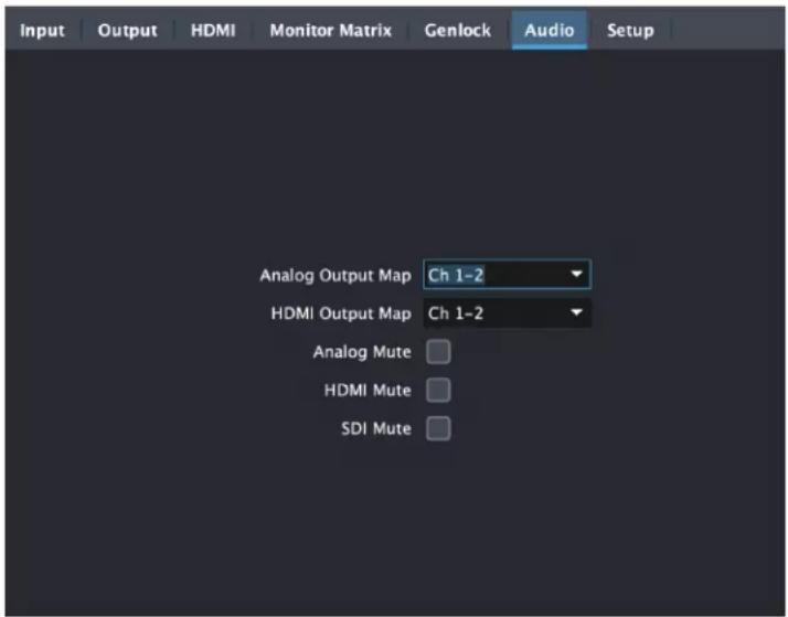
Analog Output Map
This control selects which two SDI embedded audio channels go to the two 3-pin Analog Audio Outputs. Choose from Ch 1-2, Ch 3-4, Ch 5-6, or Ch 7-8.
HDMI Output Map
This control selects which two SDI embedded audio channels go to the HDMI Output. Choose from Ch 1-2, Ch 3-4, Ch 5-6, Ch 7-8, or Ch 1-8.
Analog Mute
Select the checkbox to mute the audio on the Analog Audio Outputs.
HDMI Mute
Select the checkbox to mute the audio on the HDMI Output.
SDI Mute
Select the checkbox to mute the audio on the SDI Output.
Setup Screen
Click on the Setup tab to view and make changes to the card name, configure the reference source, or to restore card settings to factory default values.
Figure 23. OG-ROI Series Setup Tab Screen in Dashboard
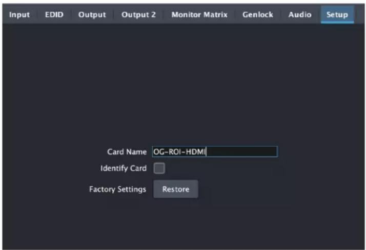
Card Name
By default, this field is pre-populated with the card name of the card you have installed—OG-ROI-HDMI, OG-ROI-DVI, or OG-ROI-SDI. You can change or customize the card name by editing the text in the Card Name field. The card name controls the name of the card that appears in the Dashboard tree view.
Identify Card
Click the checkbox to turn on Identify Card. This is especially useful when working with numerous cards and frames and you need a simple method for identifying a specific card. Click the checkbox again to turn Identify Card off.
On - Turn on if you need to identify the card. When on, the PWR LED located at the front top edge of the card will blink on and off with an orange/green color.
Off - Turn off (default) if you do not need to physically identify the card. When Identify Card is off, the PWR LED light follows the state of the card as shown in the Dashboard tree view.
- Green Icon = Green LED
• Yellow icon = yellow power LED - Red Icon = Red LED
Factory Settings
If you would like to revert the card settings to factory default values, click Restore. A confirmation window displays.
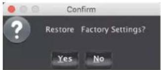
Select Yes to restore to factory settings. Select No to cancel.
Upload Screen
To Upload New Software
- Check the AJA website for new software for your OG-ROI Series. If new software is found, download it and uncompress the file archive (zip).
- Click the Upload button in the lower panel of the Dashboard Control System to open the Upload Software Wizard.
Figure 24. OG-ROI Series Upload Software Wizard window in Dashboard
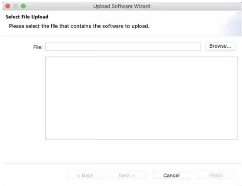
- From the Upload Software Wizard window, select Browse.
- Navigate to the location of the downloaded .bin file containing the software update. Select the .bin file, then select Open. The Upload Software Wizard window displays characteristics of the selected file for uploading.
- Click Finish. The Uploading to Selected Devices window displays with a progress bar.
Figure 25. OG-ROI Series Uploading to Selected Devices window in Dashboard
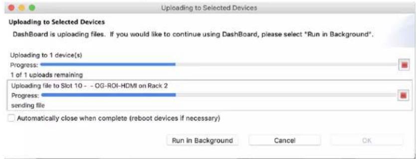
- When the progress bar indicates that the uploading is finished and status indicates "Complete," click OK.
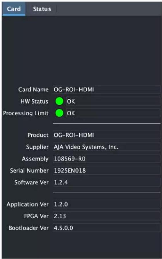
- To verify the version of software or firmware currently installed on your card, select the Card tab from the center panel of Dashboard.
Figure 26. OG-ROI Series Card Tab Screen in Dashboard indicating the currently installed software version.
Rebooting
Rebooting is a standard function built in to the Dashboard Control System, and should only be performed if the board has become unresponsive.
WARNING: During a reboot, any embedding or disembedding operations will be briefly interrupted, but will be restored once the reboot has completed.
- Click the Reboot button in the lower panel of Dashboard. The reboot confirmation message displays.
Figure 27. Reboot confirmation window
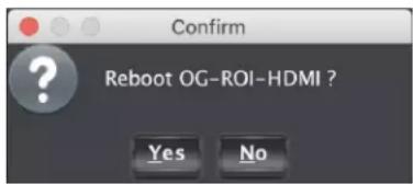
- Click Yes. The message "Loading data, please wait. Refreshing device data" displays for a moment. The card will be offline for a few seconds, and any current scan conversion operations will be interrupted.
- Following a Reboot operation, the board configuration will return to the settings that were in place at the time of rebooting.
OG-ROI-DVI Tech Specs
Video Input Formats
- Computer Signals:
• WUXGA (1920 x 1200) 60 Hz max
• VGA (640 x 480) minimum - Video Signals:
• (HD) 1920 x 1080i 50, 59.94
• (HD) 1920 x 1080p 23.98, 24, 25, 29.97, 30, 50, 59.94, 60
• (HD) 1280 x 720p 50, 59.94, 60
• (SD) 625i, 525i
• (SD) 580p, 480p
NOTE: Frame rates limited by the 165 MHz max pixel rate of the DVI receiver.
Video Output Formats
- (HD) 1920 x 1080p 50, 59.94, 60, SMPTE 425-1 Level A mapping structure 1 (4:2:2 10-bit YCbCr)
• (HD) 1920 x 1080p 23.98, 24, 25, 29.97, 30
• (HD) 1920 x 1080i 50, 59.94, 60
• (HD) 1280 x 720p 50, 59.94, 60
• (SD) 625i 25
• (SD) 525i 29.97
Color Range
• Full
- SMPTE
Reference Source
- Free Run
- Card Ext Ref
- OG Frame Ref 1
- OG Frame Ref 2
Reference Input
• Supported reference video inputs include
• 1080i tri-level sync
• 1080p tri-level sync
- 720p tri-level sync
- 625i Color Black
- 525i Color Black
- 75-ohm terminating
Video Input
- 1x DVI input connector (with embedded audio, up to 8 channels)
Video Outputs
• DVI
- 1x DVI loop through connector (with embedded audio, up to 8-channels)
• SDI
• 3G-SDI, SMPTE-259/292/424, 1x BNC
Audio Inputs
• 2-channel Balanced analog audio inputs, 2x 3-Pin terminal block connectors
• DVI embedded audio, 24-bit, 8-channel
Audio Output
• SDI embedded audio, 24-bit, 2-channel or 8-channel
User Interface
- openGear Dashboard network control software via Windows, macOS or Linux
Size
- openGear standard form factor, front slot and rear card. Two slots required for each card
Weight
• 0.5 lb (0.3 kg)
Power
- openGear frame compatible, 8.0 watts max per card
Environment
- Safe Operating Temperature: 0 to 40 C (32 to 104 F)
- Safe Storage Temperature (Power OFF): -40 to 60 C (-40 to 140 F)
- Operating Relative Humidity: 10-90% noncondensing
- Operating Altitude: <3,000 meters (<10,000 feet)
OG-ROI-HDMI Tech Specs
Video Input Formats
- Computer Signals:
• WUXGA (1920 x 1200) 60 Hz max
• VGA (640 x 480) minimum
- Video Signals:
• (HD) 1920 x 1080i 50, 59.94
• (HD) 1920 x 1080p 23.98, 24, 25, 29.97, 30, 50, 59.94, 60
• (HD) 1280 x 720p 50, 59.94, 60
• (SD) 625i, 525i
• (SD) 580p, 480p
NOTE: Frame rates limited by the 165 MHz max pixel rate of the HDMI receiver.
Video Output Formats
- (HD) 1920 x 1080p 50, 59.94, 60, SMPTE 425-1 Level A mapping structure 1 (4:2:2 10-bit YCbCr)
• (HD) 1920 x 1080p 23.98, 24, 25, 29.97, 30
• (HD) 1920 x 1080i 50, 59.94, 60
• (HD) 1280 x 720p 50, 59.94, 60
• (SD) 625i 25
• (SD) 525i 29.97
Color Range
• Full
• SMPTE
Reference Source
- Free Run
- Card Ext Ref
- OG Frame Ref 1
- OG Frame Ref 2
Reference Input
• Supported reference video inputs include
• 1080i tri-level sync
• 1080p tri-level sync
- 720p tri-level sync
- 625i Color Black
- 525i Color Black
- 75-ohm terminating
Video Input
- 1x HDMI input connector (with embedded audio, up to 8 channels)
Video Outputs
• HDMI
- 1x HDMI loop through connector (with embedded audio, up to 8 channels)
• SDI
• 3G-SDI, SMPTE-259/292/424, 1x BNC
HDCP
- ROI does not encode the HDMI output with HDCP encryption
• ROI does not accept HDCP input
Audio Inputs
• 2-channel Balanced analog audio inputs, 2x 3-Pin terminal block connectors
• HDMI embedded audio, 24-bit, 8-channel
Audio Output
• SDI embedded audio, 24-bit, 2-channel or 8-channel
User Interface
- openGear Dashboard network control software via Windows, macOS or Linux
Size
- openGear standard form factor, front slot and rear card. Two slots required for each card
Weight
• 0.5 lb (0.3 kg)
Power
- openGear frame compatible, 8.0 watts max per card
Environment
- Safe Operating Temperature: 0 to 40 C (32 to 104 F)
- Safe Storage Temperature (Power OFF): -40 to 60 C (-40 to 140 F)
- Operating Relative Humidity: 10-90% noncondensing
- Operating Altitude: <3,000 meters (<10,000 feet)
OG-ROI-SDI Tech Specs
Video Input Formats
- Video Signals:
• (HD) 1920x1080i 50, 59.94
• (HD) 1920x1080p 23.98, 24, 25, 29.97, 30, 50, 59.94, 60
• (HD) 1280x720p 50, 59.94, 60
• (SD) 625i, 50
• (SD) 525i, 59.94
Video Output Formats
- (HD) 1920x1080p 50, 59.94, 60, SMPTE 425-1 Level A mapping structure 1 (4:2:2 10-bit YCbCr)
• (HD) 1920x1080p 23.98, 24, 25, 29.97, 30
• (HD) 1920x1080i 50, 59.94, 60
• (HD) 1280x720p 50, 59.94, 60
• (SD) 625i 50
• (SD) 525i 59.94
Color Range
• Full
- SMPTE
Reference Source
- Free Run
- Ext Ref
Reference Input
• Supported reference video inputs include:
- 1080i tri-level sync
- 1080p tri-level sync
- 720p tri-level sync
- 625i Color Black
- 525i Color Black
- 75 ohm terminating
Video Input
• 1x 3G-SDI BNC, SMPTE-259/292/424
Video Outputs
• 1x 3G-SDI BNC, loop through
• 1x 3G-SDI BNC, SMPTE-259/292/424
• 1x HDMI Type A, HDMI v1.4
Audio I/O
• 24-bit, 16-channel embedded SDI audio input
• 24-bit, 16-channel embedded SDI audio output
• 24-bit, 8-channel HDMI audio output
• Balanced analog audio outputs, 2x 3-Pin terminal block connectors
User Interface
- openGear Dashboard network control software via Windows, macOS or Linux
Size
- openGear standard form factor, front slot and rear card. Two slots required for each card.
Weight
• 0.5 lb (0.3 kg)
Power
- openGear frame compatible, 7.0 watts max per card
Environment
- Safe Operating Temperature: 0 to 40 C (32 to 104 F)
- Safe Storage Temperature (Power OFF): -40 to 60 C (-40 to 140 F)
- Operating Relative Humidity: 10-90% noncondensing
- Operating Altitude: <3,000 meters (<10,000 feet)
Appendix B – Safety and Compliance
Federal Communications Commission (FCC) Compliance Notices
Class A Interference Statement
This equipment has been tested and found to comply with the limits for a Class A digital device, pursuant to Part 15, Subpart B of the FCC Rules. These limits are designed to provide reasonable protection against harmful interference in a residential installation. This equipment generates, uses, and can radiate radio frequency energy and, if not installed and used in accordance with the instructions, may cause harmful interference to radio communications. However, there is no guarantee that interference will not occur in a particular installation. If this equipment does cause harmful interference to radio or television reception, which can be determined by turning the equipment off and on, the user is encouraged to try to correct the interference by one or more of the following measures:
- Reorient or relocate the receiving antenna.
- Increase the separation between the equipment and receiver.
- Connect the equipment into an outlet on a circuit different from that to which the receiver is connected.
- Consult the dealer or an experienced radio/TV technician for help.
FCC Caution
This device complies with Part 15 of the FCC Rules. Operation is subject to the following two conditions: (1) This device may not cause harmful interference, and (2) this device must accept any interference received, including interference that may cause undesired operation.
Canadian ICES Statement
Canadian Department of Communications Radio Interference Regulations
This digital apparatus does not exceed the Class A limits for radio-noise emissions from a digital apparatus as set out in the Radio Interference Regulations of the Canadian Department of Communications. This Class A digital apparatus complies with Canadian ICES-003.
European Union and European Free Trade Association (EFTA) Regulatory Compliance
This equipment may be operated in the countries that comprise the member countries of the European Union and the European Free Trade Association. These countries, listed in the following paragraph, are referred to as The European Community throughout this document:
AUSTRIA, BELGIUM, BULGARIA, CYPRUS, CZECH REPUBLIC, DENMARK, ESTONIA, FINLAND, FRANCE, GERMANY, GREECE, HUNGARY, IRELAND, ITALY, LATVIA, LITHUANIA, LUXEMBOURG, MALTA, NETHERLANDS, POLAND, PORTUGAL, ROMANIA, SLOVAKIA, SLOVENIA, SPAIN, SWEDEN, UNITED KINGDOM, ICELAND, LICHTENSTEIN, NORWAY, SWITZERLAND
Declaration of Conformity
Marking by this symbol indicates compliance with the Essential Requirements of the EMC Directive of the European Union 2014/30/EU.

This equipment meets the following conformance standards:
Safety
EN 60065: 2002 + A1: 2006 + A11: 2008 + A2: 2010 + A12: 2011 (GS License)
IEC 60065: 2001 + A1: 2005 + A2: 2010 (CB Scheme Report/Certificate)
EN 62368-1: 2014 + A11 (T-Mark License)
IEC 62368-1: 2014 (CB Scheme Certificate)
Additional licenses issued for specific countries available on request.
Emissions
EN 55032: 2012 + AC: 2013, CISPR 32: 2015, EN 61000-3-2: 2014, EN 61000-3-3: 2013
Immunity
EN 55103-2: 2009, EN 61000-4-2: 2009, EN 61000-4-3: 2006+ A1: 2008 + A2: 2010,
EN 61000-4-4: 2012, EN 61000-4-5: 2014/A1: 2017, EN 61000-4-6: 2013,
EN 61000-4-11: 2020
Environments: E2, E3 and E4
The product is also licensed for additional country specific standards as required for the International Marketplace.

Warning! This is a Class A product. In a domestic environment, this product may cause radio interference, in which case, the user may be required to take appropriate measures.
This symbol on the product or its packaging indicates that this product must not be disposed of with your other household waste. Instead, it is your responsibility to dispose of your waste equipment by handing it over to a designated collection point for the recycling of waste electrical and electronic equipment. The separate collection and recycling of your waste equipment at the time of disposal will help conserve natural resources and ensure that it is recycled in a manner that protects human health and the environment. For more information about where you can drop off your waste for recycling, please contact your local authority, or where you purchased your product.
Korean KCC Compliance Statement
사용자 안내문
Taiwan Compliance Statement
警告使用者:
This is a Class A product based on the standard of the Bureau of Standards, Metrology and Inspection (BSMI) CNS 13438, Class A. In a domestic environment this product may cause radio interference in which case the user may be required to take adequate measures.
Japanese Compliance Statement
This is a Class A product based on the standard of the VCCI Council (VCCI-32: 2016). If this equipment is used in a domestic environment, radio interference may occur, in which case, the user may be required to take corrective actions.
Translated Warning and Caution Messages
The following caution statements, warning conventions, and warning messages apply to this product and manual.
Before Operation Please Read These Instructions

Warning! Read and follow all warning notices and instructions marked on the product or included in the documentation.
Warning! Do not use this device near water and clean only with a dry cloth.
Warning! Do not block any ventilation openings. Install in accordance with the manufacturer's instructions.
Warning! Do not install near any heat sources such as radiators, heat registers, stoves, or other apparatus (including amplifiers) that produce heat.
Warning! Refer all servicing to qualified service personnel. Servicing is required when the device has been damaged in any way, such as power-supply cord or plug is damaged, liquid has been spilled or objects have fallen into the device, the device has been exposed to rain or moisture, does not operate normally, or has been dropped.
Warning! Disconnect the external AC power supply line cord(s) from the mains power before moving the unit.
Hazard! High Voltage. This situation or condition can cause injury due to electric shock.
Warning! Only use attachments and accessories specified and/or sold by the manufacturer.
Warning! Do not defeat the safety purpose of the polarized or grounding-type plug. A polarized plug has two blades with one wider than the other. A grounding type plug has two blades and a third grounding prong. The wide blade or the third prong are provided for your safety. If the provided plug does not fit into your outlet, consult an electrician for replacement of the obsolete outlet.
Warning! Since the Mains plug is used as the disconnection for the device, it must remain readily accessible and operable.
Warning! Protect the power cord from being walked on or pinched particularly at plugs, convenience receptacles, and the point where they exit from the device.
Warning! Unplug this device during lightning storms or when unused for long periods of time.
Warning! Ensure Mains Power is disconnected before installing the OG-ROI Series modules into the frame, or installing and removing options. If a Mains switch is not provided, the power cord(s) of this equipment provide the means of disconnection. The socket outlet must be installed near the equipment and must be easily accessible.
Warning! Dual Power Cord Notice—please read this. To reduce the risk of electrical shock, disconnect both power cords before servicing equipment.
Caution! The OG-X-FR front fan door is heavy. Remove with Caution.
Warning! Do not open the chassis. There are no user-serviceable parts inside. Opening the chassis will void the warranty unless performed by an AJA service center or licensed facility.
Caution! To meet safety regulations for leakage current, connect the dual power supplies to separate branch circuits.
Warranty and Liability Information
Limited Warranty on Hardware
AJA Video Systems, Inc. (AJA Video) warrants that the hardware product, not including software components, will be free from defects in materials and workmanship for a period of five years from the date of purchase. AJA Video provides a separate software warranty as part of the license agreement applicable to software components.
If the Customer brings a valid claim under this limited warranty for a hardware product (hereafter, a "product") during the applicable warranty period, AJA Video will, at its sole option and as the Customer's sole remedy for breach of the above warranty, provide one of the following remedies:
- Repair or facilitate the repair the product within a reasonable period of time, free of charge for parts and labor.
- Replace the product with a direct replacement or with a product that performs substantially the same function as the original product.
- Issue a refund of the original purchase price less depreciation to be determined based on the age of the product at the time remedy is sought under this limited warranty.
To obtain service under this warranty, the Customer must notify AJA Video of the defect before expiration of the warranty period and make suitable arrangements for the performance of service by contacting AJA Video support through the channels set forth on the support contacts web page at https://www.aja.com/support. Except as stated, the Customer shall bear all shipping, packing, insurance and other costs, excluding parts and labor, to effectuate repair. Customer shall pack and ship the defective product to a service center designated by AJA Video, with shipping charges prepaid. AJA Video shall pay to return the product to Customer, but only if to a location within the country in which the AJA Video service center is located. SOME JURISDICTIONS DO NOT ALLOW THE EXCLUSION OF IMPLIED WARRANTIES OR LIMITATIONS ON APPLICABLE STATUTORY RIGHTS OF A CONSUMER, SO SOME OR ALL OF THE TERMS OF THIS PARAGRAPH MAY NOT APPLY TO YOU.
Limitation of Liability
Under no circumstances shall AJA video BE LIABLE IN ANY WAY FOR ANY LOST, CORRUPTED OR DESTROYED DATA, FOOTAGE OR WORK, OR FOR ANY OTHER INDIRECT, SPECIAL, INCIDENTAL OR CONSEQUENTIAL DAMAGES OR LOST PROFITS, OR FOR ANY THIRD PARTY CLAIM, IN CONNECTION WITH THE PRODUCT, WHETHER RESULTING FROM DEFECTS IN THE PRODUCT, SOFTWARE OR HARDWARE FAILURE, OR ANY OTHER CAUSE WHATSOEVER, EVEN IF AJA VIDEO HAS BEEN ADVISED OF THE POSSIBILITY OF SUCH DAMAGES. AJA VIDEO'S LIABILITY IN CONNECTION WITH THE PRODUCT SHALL UNDER NO CIRCUMSTANCES EXCEED THE PURCHASE PRICE PAID FOR THE PRODUCT. The foregoing limitations apply even if any remedy set forth in this LIMITED WARRANTY fails of its essential purpose. SOME JURISDICTIONS DO NOT ALLOW THE LIMITATION OF LIABILITY FOR PERSONAL INJURY, OR OF INCIDENTAL OR CONSEQUENTIAL DAMAGES, SO SOME OR ALL OF THE TERMS OF THIS PARAGRAPH MAY NOT APPLY TO YOU.
Governing Law and Language; Your Rights
This limited warranty is the only warranty provided by AJA Video on the hardware product. It supersedes all prior or contemporaneous understandings regarding such subject matter. No amendment to or modification of this warranty will be binding unless in writing and signed by AJA Video. The laws of the State of California, USA will govern this warranty and any dispute arising from it. Any translation of this
Agreement is intended for convenience and to meet local requirements and in the event of a dispute between the English and any non-English versions, the English version of this warranty will govern. This limited warranty gives you specific legal rights and you may have other rights that vary from jurisdiction to jurisdiction, some of which are noted above.
A
AJA Support 2
Analog Audio Input 9
Analog Audio Output 11
Analog Out Map 36
Apply Button 34
Audio Screen 35, 36
Auto Bypass Mode 23
B
Bezel Width 34
Block Diagram 8
C
Camera Video to Switcher 18
Center Button 23, 27
D
Dashboard Control Application
Audio 35, 36
EDID 24
Genlock 34
Input 22
Monitor Matrix 33
Output 26
Dashboard Control System 13
documentation 20
downloading 20
Rebooting 39
Requirements 20
Setup Tab Screen 37
Uploading New Software 38
Using 20
DVI Input 9
DVI Output 9
E
Interaction with Rotation and
Frame Delay 28
Frame Delay 28
Interaction with Rotation and
Flip 28
Full Screen Button 23
G
Genlock Control
OG-ROI-DVI 34
OG-ROI-HDMI 34
OG-ROI-SDI 34
Genlock Screen 34
H
HDCP Protection 6
H-Delay and V-Delay 35
HDMI Conversion
ROI-DVI 36
ROI-HDMI 36
HDMI Output 10
HDMI-to-DVI Adapter 9, 10
HDMI Video Input 9,10
Horizontal Flip 28
|
Input Screen 22
Input Select
ROI-DVI 36
ROI-HDMI 36
Installation 13
Cabling 16
Front Card Installation 14
Rear Card Installation 13
WECO audio mating connectors
16
I/O Connections 8
M
Matte Background 27
Max Audio Channels 25
Monitor Matrix
Representation 33
Screen 33
O
OG-ROI Configurations 17
OG-ROI-DVI 6,9
Connectors 9
Genlock Control 34
HDMI Conversion 36
Input Select 36
Signal Indicators 11
OG-ROI Features 6
OG-ROI-HDMI 6,9
Connectors 9
Genlock Control 34
HDMI Conversion 36
Input Select 36
Signal Indicators 11
OG-ROI Out Scaling
Output Scaling 26
OG-ROI Overview 5
OG-ROI-SDI 6, 10
Audio Screen 36
Connectors 10
Genlock Control 34
Signal Indicators 12
OG-ROI Selection 22
Click and Drag Options 24
openGear and AJA 8
Output Screen 26
Overview 5
P
Pixel Clock Rate 7
Preferred Video Format 25
Processing Limit Exceeded
Message 30
Resolving 30
R
Red Matte 26
Solution 7
Red SDI Output 26
Reference Video Input 8
RGB Range Menu 23
ROI Edge Filtering Checkbox
Edge Filtering Checkbox 28
Rotation 27
Illustration 28
Interaction with Flip and Frame
Delay 28
Rotation with Portrait Monitors 18
Rows 33
S
SDI Output Format 27
SDI Video Input 10
SDI Video Output 8
Signal Indicators 11
Simplified Block Diagram 8
System Interconnect Diagrams 17
T
Technical Support 2
V
Vertical Flip 28
X
X, Y, W, H 34
Y
YCbCr Support 25
- Installation and Operation Guide
- Trademarks
- Copyright
- Contacting AJA Support
- Contents
- Notices 2
- Chapter 1 – Introduction .....5
- Chapter 2 – Operation....20
- Appendix A – Specifications ..... 41
- Chapter 1 – Introduction
- Overview
- Video Processing
- Audio Handling
- OG-ROI-DVI, OG-ROI-HDMI
- OG-ROI-SDI
- HDCP Protection
- Features
- OG-ROI-DVI
- OG-ROI-HDMI
- All OG-ROI Models
- Pixel Clock Rate
- OG-ROI Processing Capabilities
- Simplified Block Diagram
- openGear and AJA
- I/O Connections
- DVI Input
- DVI Output
- Analog Audio Input
- HDMI Input
- HDMI Output
- SDI Video Input
- SDI Loop Output
- Analog Audio Output
- Signal Indicators
- OG-ROI-DVI/HDMI Card
- Power LED
- Signal Present LED
- Signal Lock LED
- Dashboard Control System
- Parts List
- Installation
- Summary
- Unpacking
- Rear OG-ROI Series Card Installation
- Front OG-ROI Series Card Installation
- Cabling
- Typical ROI Configurations
- Chapter 2 – Operation
- Using the Dashboard Control System
- Requirements
- Control Interface Basic Components
- Input Screen
- ROI Selection
- Click and Drag Options
- EDID Screen
- Preferred Video Format
- YCbCr Support
- Max Audio Channels
- Output Screen
- ROI Out Scaling
- SDI Output Format
- Matte Background
- Rotation
- Center Button
- Raster Edge Filtering Checkbox
- Flicker Filtering Checkbox
- ROI Edge Filtering Checkbox
- Frame Delay
- Horizontal Flip
- Vertical Flip
- About the Rotation, Flip, and Frame Delay Controls
- Output 2 Screen
- Loss of Input
- Mute Delay
- HDMI Screen (OG-ROI-SDI)
- HDMI/DVI
- RGB Range
- Bit Depth
- Color Space
- Monitor Matrix Screen
- Monitor Matrix Representation
- Rows
- Columns
- Bezel Width
- X, Y, W, H
- Apply
- Genlock Screen
- Genlock
- Card Ref Termination
- Reference Source
- H-Delay and V-Delay
- Audio Screen (OG-ROI-HDMI/DVI)
- Input Select
- HDMI Conversion
- Analog Out Map
- Audio Screen (OG-ROI-SDI)
- Analog Output Map
- HDMI Output Map
- Setup Screen
- Card Name
- Identify Card
- Factory Settings
- Upload Screen
- To Upload New Software
- Rebooting
- OG-ROI-DVI Tech Specs
- Video Input Formats
- Video Output Formats
- Color Range
- Reference Input
- Video Input
- Video Outputs
- Audio Inputs
- Audio Output
- User Interface
- Size
- Weight
- Power
- Environment
- OG-ROI-HDMI Tech Specs
- HDCP
- OG-ROI-SDI Tech Specs
- Audio I/O
- Appendix B – Safety and Compliance
- Federal Communications Commission (FCC) Compliance Notices
- Class A Interference Statement
- FCC Caution
- Canadian ICES Statement
- European Union and European Free Trade Association (EFTA) Regulatory Compliance
- Declaration of Conformity
- Safety
- Emissions
- Immunity
- Korean KCC Compliance Statement
- Taiwan Compliance Statement
- 警告使用者:
- Japanese Compliance Statement
- Translated Warning and Caution Messages
- Before Operation Please Read These Instructions
- Warranty and Liability Information
- Limited Warranty on Hardware
- Limitation of Liability
- Governing Law and Language; Your Rights
- A
- B
- C
- D
- E
- G
- H
- |
- M
- O
- P
- R
- S
- T
- V
- X
- Y
Brand : AJA
Model : ROI-SDI
Category : Uncategorized