
WISE-4050-AE - Network card / adapter Advantech - Free user manual and instructions
Find the device manual for free WISE-4050-AE Advantech in PDF.


| Product Type | IoT Wireless I/O Module (Network Card/Adapter) |
| Brand | Advantech |
| Model | WISE-4050-AE |
| Digital Inputs | 4 channels (dry/wet contact, 3000 Vrms isolation, 32-bit counter, frequency up to 3 kHz) |
| Digital Outputs | 4 channels (open collector, 30 V/500 mA max, 3000 Vrms isolation, pulse output up to 5 kHz) |
| Wireless Interface | 802.11b/g/n (2.4 GHz), AP or Infrastructure mode, WPA2 Personal/Enterprise |
| Ethernet Interface | Not applicable (wireless model) |
| Power Supply | 10-30 VDC (24 VDC standard), reverse polarity protection |
| Power Consumption | 2.2 W @ 24 VDC typical |
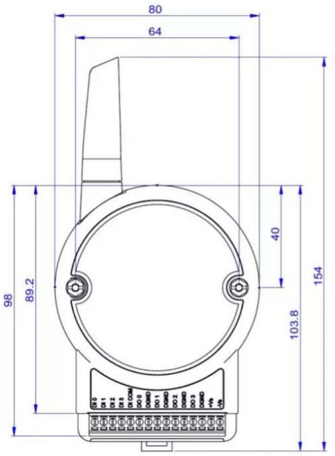
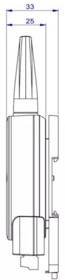
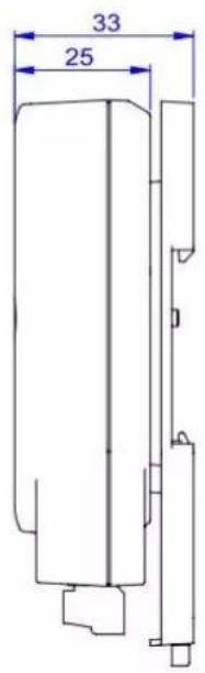
| Dimensions (with antenna) | 80 x 148 x 25 mm |
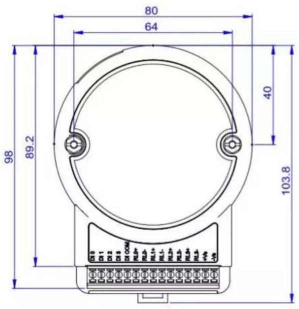
| Dimensions (without antenna) | 80 x 89 x 25 mm |
| Weight | Approx. 150 g (estimated) |
| Operating Temperature | -25 to +70°C (-13 to 158°F) |
| Storage Temperature | -40 to +85°C (-40 to 185°F) |
| Operating Humidity | 20-95% RH (non-condensing) |
| Enclosure Material | PC (polycarbonate) |
| Mounting | DIN rail, wall, or stack mount |
| I/O Connector | 3.5 mm spacing, 15-pole plug-in screw terminal |
| Antenna Connector | Reverse SMA |
| Protocols Supported | Modbus/TCP, RESTful Web API (JSON), HTTP/HTTPS, DHCP, SNTP |
| Data Logger | Internal flash for up to 10,000 samples with timestamp; periodic or event-triggered logging |
| Cloud Integration | Push data to public cloud (Dropbox, Baidu) or private cloud via REST API |
| Certifications | FCC Part 15 Class A, CE, KC |
| Safety Instructions | Do not cover openings, keep away from moisture, use correct voltage, professional servicing only |
| Spare Parts / Repairability | No user-serviceable parts; contact authorized service for repairs |
Frequently Asked Questions - WISE-4050-AE Advantech
User questions about WISE-4050-AE Advantech
0 question about this device. Answer the ones you know or ask your own.
Ask a new question about this device
Download the instructions for your Network card / adapter in PDF format for free! Find your manual WISE-4050-AE - Advantech and take your electronic device back in hand. On this page are published all the documents necessary for the use of your device. WISE-4050-AE by Advantech.
USER MANUAL WISE-4050-AE Advantech
The documentation and the software included with this product are copyrighted 2015 by Advantech Co., Ltd. All rights are reserved. Advantech Co., Ltd. reserves the right to make improvements in the products described in this manual at any time without notice. No part of this manual may be reproduced, copied, translated or transmitted in any form or by any means without the prior written permission of Advantech Co., Ltd. Information provided in this manual is intended to be accurate and reliable. However, Advantech Co., Ltd. assumes no responsibility for its use, nor for any infringements of the rights of third parties, which may result from its use.
Acknowledgements
Intel and Pentium are trademarks of Intel Corporation.
Microsoft Windows and MS-DOS are registered trademarks of Microsoft Corp.
All other product names or trademarks are properties of their respective owners.
Product Warranty
Advantech warrants to you, the original purchaser, that each of its products will be free from defects in materials and workmanship for two years from the date of purchase.
This warranty does not apply to any products which have been repaired or altered by persons other than repair personnel authorized by Advantech, or which have been subject to misuse, abuse, accident or improper installation. Advantech assumes no liability under the terms of this warranty as a consequence of such events.
Because of Advantech's high quality-control standards and rigorous testing, most of our customers never need to use our repair service. If an Advantech product is defective, it will be repaired or replaced at no charge during the warranty period. For out-of-warranty repairs, you will be billed according to the cost of replacement materials, service time and freight. Please consult your dealer for more details.
If you think you have a defective product, follow these steps:
-
Collect all the information about the problem encountered. (For example, CPU speed, Advantech products used, other hardware and software used, etc.) Note anything abnormal and list any onscreen messages you get when the problem occurs.
-
Call your dealer and describe the problem. Please have your manual, product, and any helpful information readily available.
-
If your product is diagnosed as defective, obtain an RMA (return merchandise authorization) number from your dealer. This allows us to process your return more quickly.
-
Carefully pack the defective product, a fully-completed Repair and Replacement Order Card and a photocopy proof of purchase date (such as your sales receipt) in a shippable container. A product returned without proof of the purchase date is not eligible for warranty service.
-
Write the RMA number visibly on the outside of the package and ship it prepaid to your dealer.
Part No. 2003D40003 Edition 4
Printed in Taiwan May 2016
Declaration of Conformity
CE
This product has passed the CE test for environmental specifications. We recommend the use of shielded cables.
FCC Class A
Note: This equipment has been tested and found to comply with the limits for a Class A digital device, pursuant to part 15 of the FCC Rules. These limits are designed to provide reasonable protection against harmful interference when the equipment is operated in a commercial environment. This equipment generates, uses, and can radiate radio frequency energy and, if not installed and used in accordance with the instruction manual, may cause harmful interference to radio communications. Operation of this equipment in a residential area is likely to cause harmful interference in which case the user will be required to correct the interference at his own expense.
KC
Trade name or Applicant name: Advantech
Equipment name: IoT Wireless I/O Module
Basic model name:
WISE-4012
WISE-4050
Certificate number:
WISE-4012: MSIP-CRM-AK0-WISE-4012
WISE-4050: MSIP-CRM-AK0-WISE-4050
Manufacture / Country of Origin: Advantech Taiwan
The date for certificate issue: 2016
Type of identification: Wi-Fi I/O
Technical Support and Assistance
- Visit the Advantech web site at www.advantech.com/support where you can find the latest information about the product.
- Contact your distributor, sales representative, or Advantech's customer service center for technical support if you need additional assistance. Please have the following information ready before you call:
– Product name and serial number
– Description of your peripheral attachments
– Description of your software (operating system, version, application software, etc.)
– A complete description of the problem - The exact wording of any error messages
Safety Instructions
- Read these safety instructions carefully.
- Keep this User Manual for later reference.
- Disconnect this equipment from any AC outlet before cleaning. Use a damp cloth. Do not use liquid or spray detergents for cleaning.
-
For plug-in equipment, the power outlet socket must be located near the equipment and must be easily accessible.
-
Keep this equipment away from humidity.
-
Put this equipment on a reliable surface during installation. Dropping it or letting it fall may cause damage.
-
The openings on the enclosure are for air convection. Protect the equipment from overheating. DO NOT COVER THE OPENINGS.
-
Make sure the voltage of the power source is correct before connecting the equipment to the power outlet.
-
Position the power cord so that people cannot step on it. Do not place anything over the power cord.
-
All cautions and warnings on the equipment should be noted.
-
If the equipment is not used for a long time, disconnect it from the power source to avoid damage by transient overvoltage.
-
Never pour any liquid into an opening. This may cause fire or electrical shock.
-
Never open the equipment. For safety reasons, the equipment should be opened only by qualified service personnel.
-
If one of the following situations arises, get the equipment checked by service personnel:
– The power cord or plug is damaged.
– Liquid has penetrated into the equipment.
– The equipment has been exposed to moisture.
- The equipment does not work well, or you cannot get it to work according to the user's manual.
– The equipment has been dropped and damaged.
– The equipment has obvious signs of breakage.
-
DO NOT LEAVE THIS EQUIPMENT IN AN ENVIRONMENT WHERE THE STORAGE TEMPERATURE MAY GO BELOW -20°C (-4°F) OR ABOVE 60°C (140°F). THIS COULD DAMAGE THE EQUIPMENT. THE EQUIPMENT SHOULD BE IN A CONTROLLED ENVIRONMENT.
-
CAUTION: DANGER OF EXPLOSION IF BATTERY IS INCORRECTLY REPLACED. REPLACE ONLY WITH THE SAME OR EQUIVALENT TYPE RECOMMENDED BY THE MANUFACTURER, DISCARD USED BATTERIES ACCORDING TO THE MANUFACTURER'S INSTRUCTIONS.
-
The sound pressure level at the operator's position according to IEC 704-1:1982 is no more than 70 dB (A).
DISCLAIMER: This set of instructions is given according to IEC 704-1. Advantech disclaims all responsibility for the accuracy of any statements contained herein.
Contents
Chapter 1 Product Overview....1
1.1 Introduction 2
1.2 Feature Highlights .... 2
1.2.1 RESTful Web Service 2
1.2.2 Data Storage Function 3
1.2.3 IoT Cloud Function.... 3
s Family and Specifications 4
1.3.1 Series Family 4
1.4 Mechanical Design and Dimensions 5
1.4.1 WISE-4000 Wireless Series Dimensions.... 5
1.4.2 WISE-4000/LAN Dimensions.... 5
1.5 Switch....6
1.6 LED Definition 6
1.7 Certification and Safety Standard 7
1.8 Package Information 8
Chapter 2 Product Specifications....9
2.1 General Specifications ...... 10
2.2 WISE-4010/LAN.... 12
2.2.1 I/O Specification.... 12
2.2.2 Application Wiring 13
Figure 2.1 WISE-4010/LAN Current Input Wiring Diagram ..... 13
Figure 2.2 WISE-4010/LAN Digital Output Wiring Diagram..... 13
2.2.3 Pin Assignment 14
Figure 2.3 WISE-4010/LAN Pin Assignment .... 14
2.2.4 Block Diagram.... 14
Figure 2.4 WISE-4010/LAN Block Diagram.... 14
2.3 WISE-4050/LAN.... 14
2.3.1 I/O Specification.... 14
2.3.2 Application Wiring 15
Figure 2.5 WISE-4050/LAN Digital Input Wiring Diagram ..... 15
Figure 2.6 WISE-4050/LAN Digital Output Wiring Diagram..... 15
2.3.3 Pin Assignment 16
Figure 2.7 WISE-4050/LAN Pin Assignment .... 16
2.3.4 Block Diagram.... 16
Figure 2.8 WISE-4050/LAN Block Diagram.... 16
2.4 WISE-4060/LAN....17
2.4.1 I/O Specification.... 17
2.4.2 Application Wiring 18
Figure 2.9 WISE-4060/LAN Digital Input Wiring Diagram ..... 18
Figure 2.10WISE-4060/LAN Relay Output Wiring Diagram ..... 18
2.4.3 Pin Assignment 19
Figure 2.11WISE-4060/LAN Pin Assignment 19
2.4.4 Block Diagram.... 19
Figure 2.12WISE-4060/LAN Block Diagram.... 19
2.5 WISE-4012E 20
2.5.1 I/O Specification.... 20
2.5.2 Application Wiring 22
Figure 2.13WISE-4012E Voltage Input Wiring Diagram.... 22
Figure 2.14WISE-4012E Digital Input Wiring Diagram.... 22
Figure 2.15WISE-4012E Relay Output Wiring Diagram.... 22
2.5.3 Pin Assignment.... 23
Figure 2.16WISE-4012E Pin Assignment.... 23
2.5.4 Block Diagram 23
Figure 2.17WISE-4012E Block Diagram 23
2.6 WISE-4012.... 24
2.6.1 I/O Specification.... 24
2.6.2 Application Wiring 25
Figure 2.18WISE-4012 Analog Input Wiring Diagram 25
Figure 2.19WISE-4012 Digital Input Wiring Diagram 25
Figure 2.20WISE-4012 Digital Output Wiring Diagram ...... 25
2.6.3 Pin Assignment.... 26
Figure 2.21WISE-4012 Pin Assignment 26
2.6.4 Block Diagram 26
Figure 2.22WISE-4012 Block Diagram.... 26
2.7 WISE-4050.... 27
2.7.1 I/O Specification.... 27
2.7.2 Application Wiring 28
Figure 2.23WISE-4050 Digital Input Wiring Diagram 28
Figure 2.24WISE-4050 Digital Output Wiring Diagram ...... 28
2.7.3 Pin Assignment.... 28
Figure 2.25WISE-4050 Pin Assignment 28
2.7.4 Block Diagram 29
Figure 2.26WISE-4050 Block Diagram.... 29
2.8 WISE-4051.... 29
2.8.1 I/O Specification.... 29
2.8.2 Application Wiring 30
Figure 2.27WISE-4051 Digital Input Dry Contact Wiring Diagram. 30
Figure 2.28WISE-4051 Digital Input Wet Contact Wiring Diagram 30
Figure 2.29RS-485 Port Wiring Diagram.... 31
2.8.3 Pin Assignment.... 31
Figure 2.30WISE-4051 Pin Assignment .... 31
2.8.4 Block Diagram 31
Figure 2.31WISE-4051 Block Diagram.... 31
2.9 WISE-4060.... 32
2.9.1 I/O Specification.... 32
2.9.2 Application Wiring 33
Figure 2.32WISE-4060 Digital Input Wiring Diagram ...... 33
Figure 2.33WISE-4060 Relay Output Wiring Diagram .... 33
2.9.3 Pin Assignment.... 33
Figure 2.34WISE-4060 Pin Assignment 33
2.9.4 Block Diagram 34
Figure 2.35WISE-4060 Block Diagram.... 34
Chapter 3 Hardware Installation.... 35
3.1 Interface Introduction ...... 36
3.2 Mounting 36
3.2.1 DIN-Rail Mounting 36
Figure 3.1 Mounting Kit Back View.... 36
Figure 3.2 Installing the Mounting Kit for a DIN-Rail ...... 36
Figure 3.3 Mounting on the DIN-Rail 37
Figure 3.4 Rear View of DIN-Rail Mounting 37
3.2.2 Wall Mounting 38
Figure 3.5 Mounting Kit Dimensions.... 38
Figure 3.6 Wall Mounting.... 39
Figure 3.7 Wall Mounting Finished 39
3.2.3 Stack Mounting 40
Figure 3.8 Stack Mounting.... 40
Figure 3.9 Finished Stack Mounting 40
3.3 Wiring & Connections.... 41
3.3.1 Power Supply Wiring (Not for WISE-4012E).... 41
Figure 3.10 Power Supply Wiring 41
3.3.2 USB Power (WISE-4012E Only).... 41
Figure 3.11USB Power Supply Wiring.... 42
3.3.3 I/O Units 42
Chapter 4 System Configuration ....43
4.1 Connection 44
4.2 Configure WISE Using the Web Interface.... 44
4.2.1 System Requirements.... 44
4.2.2 List of WISE-4000 Default Ethernet Ports 45
4.2.3 Factory Default Settings.... 45
4.2.4 Module Authorization 45
4.2.5 Operation Mode 45
4.2.6 Using a Browser to Configure the Module 46
4.2.7 Configuring the RS-485 Port of WISE-4051 61
Figure 4.1 Application Scenario of WISE-4051 RS-485 Port with ADAM-4000 Modbus I/O Module....66
Table 4.1: Application Scenario of WISE-4051 RS-485 Port with ADAM-4000 Modbus I/O Module....67
4.2.8 Configuring Cloud Server (WISE-4000 wireless series only)..... 79
4.3 Configure WISE-4000 with ADAM.NET Utility 82
4.3.1 Operation Framework 82
4.3.2 Configure WISE-4000 87
4.4 Site Survey Tool for WISE-4000 Wireless Series 90
4.4.1 Site Survey Architecture 90
4.4.2 Site Survey Mode....90
4.4.3 Site Survey Tool....91
Appendix A I/O Modbus Mapping Table......93
A.1 Modbus Function Code Introduction 94
A.2 WISE-4010/LAN Modbus Mapping Table 94
A.3 WISE-4050/LAN Modbus Mapping Table 98
A.5 WISE-4012E Wireless Modbus Mapping Table 102
A.6 WISE-4012 Wireless Modbus Mapping Table 105
A.7 WISE-4050 Wireless Modbus Mapping Table 110
A.8 WISE-4051 Wireless Modbus Mapping Table 112
A.9 WISE-4060 Wireless Modbus Mapping Table 114
Appendix B REST for WISE-4000 Series .....117
B.1 Introduction ...... 118
B.2 REST Resources for WISE-4000 Series.... 119
B.2.1 Digital Input.... 119
B.2.2 Digital Output 124
B.2.3 Analog Input.... 129
B.2.4 RS-485 Port Expansion Data.... 135
B.2.5 Data Logger 143
Chapter 1
Product Overview
1.1 Introduction
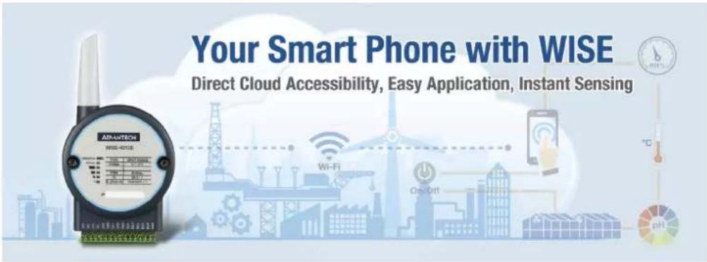
WISE-4000 series is an Ethernet-based wired or wireless IoT device, which integrated with IoT data acquisition, processing, and publishing functions. Except various I/O type offering, WISE-4000 series provides data pre-scaling, data logic, and data logger functions. These data can be access via mobile devices and be published to cloud with security in anytime and anywhere.
1.2 Feature Highlights
1.2.1 RESTful Web Service
Representational State Transfer (REST) is a software architecture style widely used for creating scalable web services. With the advantage of scalability, simplicity and performance, it's already adopted in IoT applications. It is based on Hypertext Transfer Protocol (HTTP) and uses verbs, like GET, POST, PUT, DELETE, etc., for web browsers to get web pages or retrieve data with remote servers. The data can be retrieved by internet media like HTML, XML, or JSON. REST s a uniform resource identifier (URI) to identify the data. Like using "http://10.0.0.1/analoginput/ch0" to identify the analog input value of channel 0. Then the web server may retrieve a JSON file analog input value of channel 0.
Automation Protocol
Modbus/TCP Master
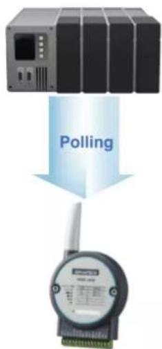
flowchart
graph TD
    A["Device"] -->|Polling| B["Digital Meter"]
Modbus/TCP Slave
RESTful Web API
Web Client
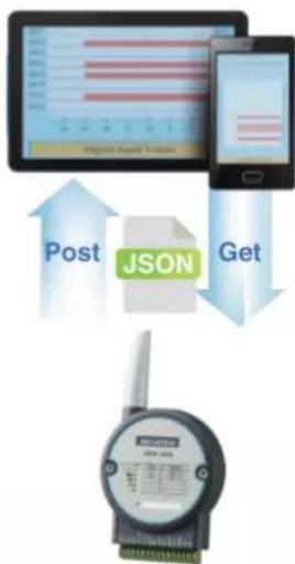
flowchart
graph TD
    A["Input Data"] --> B["Post"]
    B --> C["JSON Processing"]
    C --> D["Get"]
    D --> E["Device Monitoring"]
Web Server
1.2.2 Data Storage Function
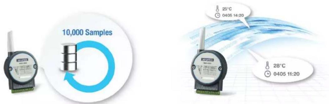
The internal flash of the WISE module can log up to 10,000 data samples with a time stamp. The I/O data can be logged periodically, and when the I/O status changes. Once the memory is full, users can choose to overwrite the old data to ring log or just stop the log function. When the module is powered-off, data can be kept in the module. When restarting, users can decide whether to clear all data or continue logging.
The definition of data in the IoT is not only the status of everything, but also includes time or location information. With a built-in Real Time Clock (RTC), WISE modules log data with a time stamp and the MAC address of the WISE module. The internal RTC can be calibrated by SNTP with time server. Once the module has been powered-off, the internal time can also be saved using the time backup battery. When users poll the data from the data logger, the time stamp will always be attached to the data.
1.2.3 IoT Cloud Function
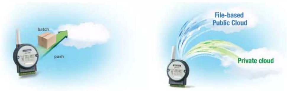
Local storage data not only can be polled by the user, it can also be pushed to the cloud automatically. Once the logger reaches the upload criteria, Data Logger will push the data to public cloud services like Dropbox or Baidu. This data will be saved on the cloud using a *.csv file extension. Users can synchronize the data on the cloud using the application program provided by the cloud provider where it can be accessed from anywhere. With the provided RESTful API, users can configure their private cloud and push the data onto it. Cloud Logger provides a very flexible solution for cloud data storage. A WISE module is the only one stop from data acquisition to the cloud.
flowchart
graph TD
    A["File-based Public Cloud"] --> B["Private cloud"]
    C["batch"] --> D["push"]
    style A fill:#f9f,stroke:#333
    style B fill:#ccf,stroke:#333
    style C fill:#cfc,stroke:#333
    style D fill:#fcc,stroke:#333
1.3 Series Family and Specifications
1.3.1 Series Family
| Interface | Model Description | |
| WLAN | WISE-4012E | 6-ch Input/OutputIoT Wireless I/O Module for IoT Developers |
| WISE-4012 | 4-ch Universal Input and 2-ch Digital OutputIoT Wireless I/O Module | |
| WISE-4050 | 4-ch Digital Input and 4-ch Digital OutputIoT Wireless I/O Module | |
| WISE-4051 | 8-ch Digital InputIoT Wireless I/O Module with 1-port RS-485 | |
| WISE-4060 | 4-ch Digital Input and 4-ch Relay OutputIoT Wireless I/O Module | |
| LAN | WISE-4010/LAN | 4-ch Current Input and 4-ch Digital OutputIoT Ethernet I/O Module |
| WISE-4050/LAN | 4-ch Digital Input and 4-ch Digital OutputIoT Ethernet I/O Module | |
| WISE-4060/LAN | 4-ch Digital Input and 4-ch Relay OutputIoT Ethernet I/O Module |
1.4 Mechanical Design and Dimensions
1.4.1 WISE-4000 Wireless Series Dimensions
1.4.2 WISE-4000/LAN Dimensions
1.5 Switch
| Switch Description Position ON (Default) OFF | |||
| SW1 Operation Mode | P1 Normal Mode Initial Mode | ||
| P2 N/A N/A | |||
| SW2 | DI Type(Ch0~3) | P1 Dry Contact | Wet Contact |
| P2 Dry Contact | Wet Contact | ||
| SW3 | DI Type(Ch4~7) | P1 Dry Contact | Wet Contact |
| P2 Dry Contact | Wet Contact | ||
Note 1 After the position 1 of SW1 been changed, user need to power on the module again to apply the operation mode
Note 2 SW2 is for WISE-4051, WISE-4050(/LAN), and WISE-4060(/LAN), all 4 channels have to be configured to dry contact or wet contact in the same time, and both P1 and P2 have to be changed together
Note 3 SW3 is for WISE-4051 only, all 4 channels have to be configured to dry contact or wet contact in the same time, and both P1 and P2 have to be changed together
1.6 LED Definition
WISE-4000 Wireless Series
| LED | Color | Indication | Behavior |
| Status | Green | Blink | 2Hz: Wait for connection0.5Hz: Network Connected |
| ON 30 Sec | When enable LOCATE function. | ||
| Com | Yellow | Blink When TX/RX data in transmission | |
| AP/Infra | Green | ON | Limited AP Mode |
| OFF | Station Mode | ||
| Signal Strength | Green | ON *4 | Full Signal |
| ON *3 | Good Signal | ||
| ON *2 | Okay Signal | ||
| ON *1 | Poor Signal | ||
| All OFF | No Signal/ Limited AP Mode | ||
WISE-4051 Only
| LED | Color | Indication | Behavior |
| Tx | Yellow | Blink | RS-485 port is transmitting data |
| Rx | Green | Blink | RS-485 port is receiving data |
WISE-4000/LAN Series
| LED Color | Indication | Behavior | |
| Status | Green | Blink Module is normally at work. (1Hz) | |
| ON 30 Sec | When enable LOCATE function. | ||
| Com | Yellow | Blink | When TX/RX data in transmission |
| Link | Green | ON | Both ends of devices are connected |
| Speed | Yellow | ON/OFF | ON: 100 MbpsOFF: Less than 10 Mbps |
1.7 Certification and Safety Standard
WISE-4000/LAN Series
FCC - FCC Part 15 Class A - IC ICES-003
CE - EN 55011 (Group 1, CLASS A) - EN 55022 - EN 61000-6-4 - EN 61000-6-2 - IEC 61000-4-2 - IEC 61000-4-3 - IEC 61000-4-4 - IEC 61000-4-5 - IEC 61000-4-6 - IEC 61000-4-8 - IEC 61000-4-11 - RoHS
China RoHS
WISE-4000 Wireless Series
- FCC - FCC Part 15 Class A - IC ICES-003
CE - EN 55011 (Group 1, CLASS A) - EN 55022 - EN 61000-6-4 - EN 61000-6-2 - IEC 61000-4-2 - IEC 61000-4-3 - IEC 61000-4-4 - IEC 61000-4-5 - IEC 61000-4-6 - IEC 61000-4-8 - IEC 61000-4-11 - RoHS
■ NCC ■ SRRC ■ China RoHS
1.8 Package Information
WISE-4000 Wireless Series
WISE-4000 Module with bundle antenna and terminal connector x1
■ Mounting bracket x1
■ Quick startup manual with China RoHS declare
WISE-4000/LAN Series
WISE-4000/LAN Module
■ Mounting bracket x1
■ Quick startup manual with China RoHS declare
WISE-4012
WISE-4000 Module with bundle antenna and terminal connector x1
■ Mounting bracket x1
■ Quick startup manual with China RoHS declare
■ 120Ohm precise resistors
WISE-4012E
WISE-4012E Module with bundle antenna and terminal connector x1
■ Quick startup manual with China RoHS declare
USB drive with WebAccess (WISE-4012E-AE-WA only)
USB power cable
■ Extension board
Screwdriver
Chapter 2
Product Specifications
2.1 General Specifications
WLAN Interface
Standard Conformance:
-802.11b
-802.11g
- 802.11n (2.4GHz only)
Network Modes:
– Limited AP (Wireless Server)
– Station/Infrastructure (Wireless Client)
■ Transmission Distance: 110 meters (In open areas with bundled external antenna)
■ Wireless Security: WPA2 Personal & Enterprise
■ Transmit Power
- 802.11b: 15.00 dBm
- 802.11g: 16.45 dBm
- 802.11n: 16.39 dBm
Antenna
- Connector: Reverse SMA
– Gain (Peak): 3.26 dBi
LAN Interface (WISE-4000/LAN Series)
Ethernet: IEEE 802.3u 10/100Base-T(X)
Connector: 1-port RJ-45
General
■ I/O Connector: 3.5mm spacing, 15-pole, plug-in screw terminal block
■ Power Connector: Micro-B USB for WISE-4012E, other modules use same connector as I/O
Watchdog Timer
- System: 1.6 second
- Communication
- Programmable (FSV)
■ RTC Accuracy: 3 min/month (WISE-4012E does not provide RTC)
■ Enclosure: PC
■ Mounting: DIN 35 rail, wall, and stack
■ Dimensions (W x H x D)
- With bundle antenna: 80 x 148 x 25 mm
- Without bundled antenna: 80 × 89 × 25 ~mm
■ Operation Temperature:
- WISE-4000 Wireless Series: -25\~70°C (-13\~158°F)
- WISE-4000/LAN Series: -40\~70°C (-40\~158°F)
■ Cold Start Temperature
- WISE-4000 Wireless Series: -20\~70°C (-4\~158°F)
- WISE-4000/LAN Series: -40\~70°C (-40\~158°F)
■ Storage Temperature: -40\~85°C (-40\~185°F)
- Operating Humidity: 20\~95% RH (non-condensing)
■ Storage Humidity: 0\~95% RH (non-condensing)
Note! Equipment will operate below 30% humidity. However, static electricity problems occur much more frequently at lower humidity levels. Make sure you take adequate precautions when you touch the equipment. Consider using ground straps, anti-static floor coverings, etc. if you use the equipment in low humidity environments.
Power
Power Input Voltage
- WISE-4012E: USB 5VDC
- WISE-4012: 10\~30 VDC (24 VDC Standard)
- WISE-4050: 10\~30 VDC (24 VDC Standard)
- WISE-4051: 10\~30 VDC (24 VDC Standard)
- WISE-4060: 10\~30 VDC (24 VDC Standard)
- WISE-4010/LAN: 10\~30 VDC (24 VDC Standard)
- WISE-4050/LAN: 10\~30 VDC (24 VDC Standard)
- WISE-4060/LAN: 10\~30 VDC (24 VDC Standard)
Power Consumption
- WISE-4012E: 2.2 W @ 5 VDC
- WISE-4012: 2.5 W @ 24 VDC
- WISE-4050: 2.2 W @ 24 VDC
- WISE-4051: 2.2 W @ 24 VDC
- WISE-4060: 2.5 W @ 24 VDC
- WISE-4010/LAN: 1.2 W @ 24 VDC
- WISE-4050/LAN: 2.2 W @ 24 VDC
- WISE-4060/LAN: 2.5 W @ 24 VDC
■ Reverse Power Protection (not for WISE-4012E)
Software
■ Configuration Interface: Web Interface, Windows Utility
■ Utility: WISE-4000/Apax .NET Utility
Driver: WISE-4000 .NET Class Library
Industrial Protocol: Modbus/TCP
■ Supported Protocols: TCP/IP, UDP, HTTP, HTTPS, DHCP, ARP, SNTP
■ Supports RESTful Web API in JSON format
■ Supports Web Server in HTML5 with JavaScript & CSS3
Note!RTC Accuracy: 3 min/month (WISE-4012E does not provide RTC)

2.2 WISE-4010/LAN
2.2.1 I/O Specification
Current Input
- Channel: 4
- Resolution: 12-bit
– Sampling Rate: 10/100 Hz/channel
– Accuracy: ±0.2% of FSR @ 25°C - Input Range: 0\~20 mA, 4\~20 mA (Select by Web Configuration)
- Input Impedance: 120 Ω
– Burn-out Detection: Yes (4\~20 mA only)
– Supports Data Scaling and Averaging
Digital Output
- Channels: 4
-Open collector to 30V , 400mA max. for resistance load - Inductive loads require an external diode to eliminate back-EMF when the DO is turned off
- On Resistance (R _DS(ON) ): 0.7 Ω (max.) @ 400mA, 25°C, 10V
– Supports 5 kHz Pulse Output
– Supports High-to-Low and Low-to-High Delay Output
2.2.2 Application Wiring
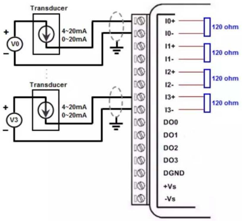
Figure 2.1 WISE-4010/LAN Current Input Wiring Diagram
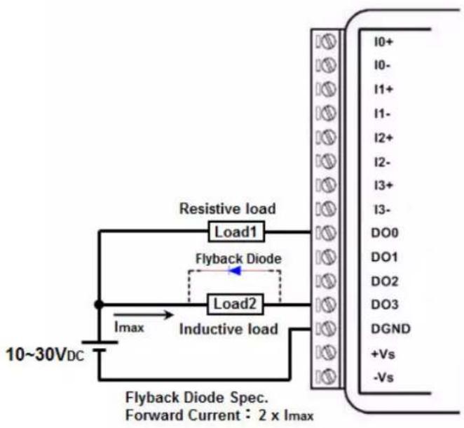
Figure 2.2 WISE-4010/LAN Digital Output Wiring Diagram
2.2.3 Pin Assignment
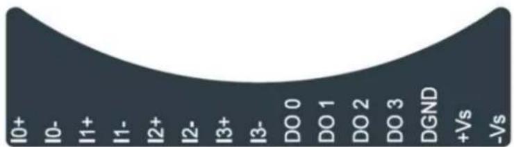
Figure 2.3 WISE-4010/LAN Pin Assignment
2.2.4 Block Diagram
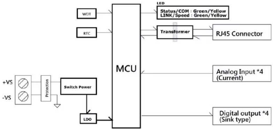
flowchart
graph TD
    A["+VS"] --> B["Protection"]
    C["-VS"] --> B
    B --> D["Switch Power"]
    D --> E["LDO"]
    E --> F["MCU"]
    G["WDT"] --> F
    H["RTC"] --> F
    I["LED"] --> F
    J["Transformer"] --> K["RJ45 Connector"]
    L["Analog Input *4 (Current)"] --> F
    M["Digital output *4 (Sink type)"] --> F
    N["Status/COM : Green/Yellow LINK/Speed : Green/Yellow"] --> F
Figure 2.4 WISE-4010/LAN Block Diagram
2.3 WISE-4050/LAN
2.3.1 I/O Specification
Digital Input
- Channel: 4
- Logic level
-Dry Contact 0: Open
1: Close to DI COM
-Wet Contact 0: 0\~3 V DC or -3\~0 V DC
1: 10\~30 V DC or -30\~-10 V DC (3 mA min.)
-All 4 channels should be configured to dry contact or wet contact in the same time
- Isolation: 3,000 V rms
– Supports 32-bit Counter Input Function (Maximum signal frequency 3 kHz) - Keep/Discard Counter Value when Power-off
– Supports Frequency Input Function (Maximum frequency 3 kHz)
– Supports Inverted DI Status
Digital Output
- Channels: 4
- Open collector to 30 V, 400 mA max. for resistance load
- Inductive loads require an external diode to eliminate back-EMF when the DO is turned off
- Isolation: 3,000 V rms
- On Resistance (R _DS(ON) ): 0.7 Ω (max.) @ 400mA, 25°C, 10V
– Supports 5 kHz Pulse Output
– Supports High-to-Low and Low-to-High Delay Output
2.3.2 Application Wiring
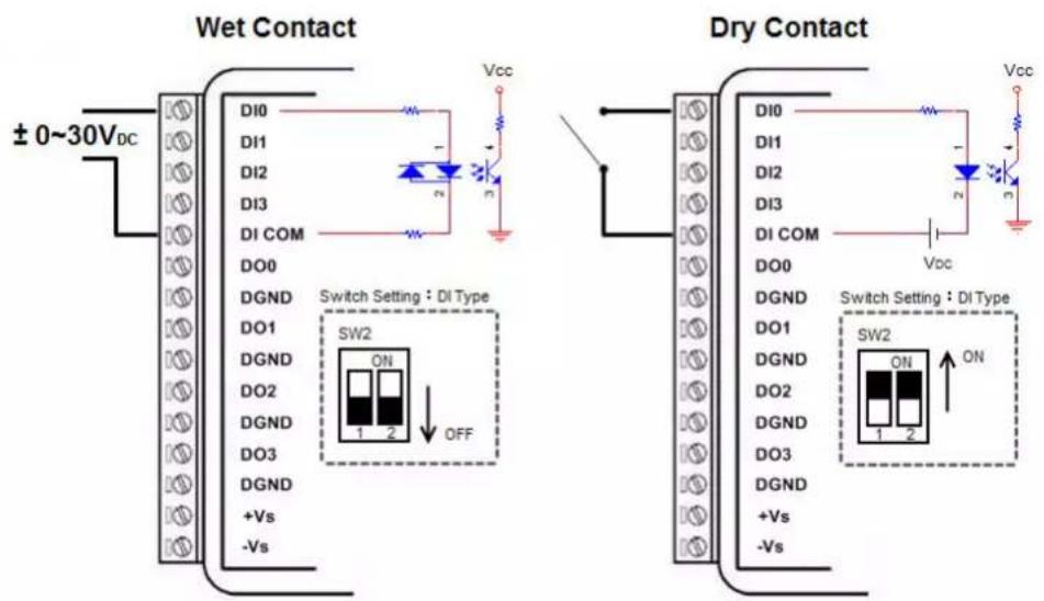
Figure 2.5 WISE-4050/LAN Digital Input Wiring Diagram
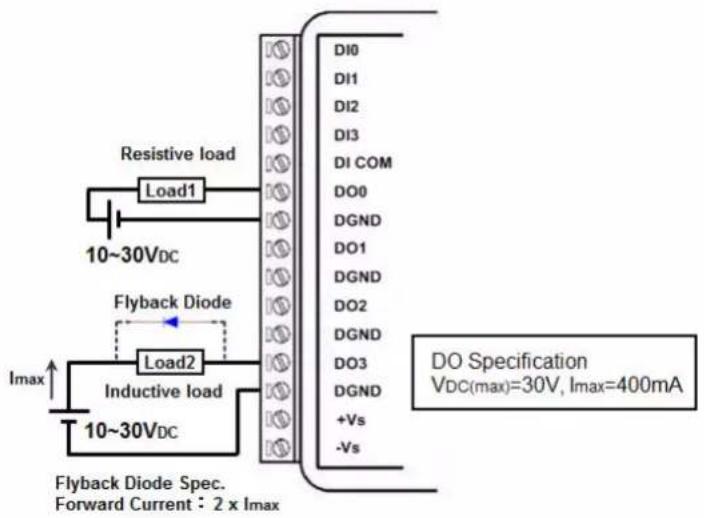
Figure 2.6 WISE-4050/LAN Digital Output Wiring Diagram
2.3.3 Pin Assignment
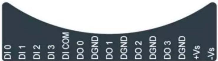
Figure 2.7 WISE-4050/LAN Pin Assignment
2.3.4 Block Diagram
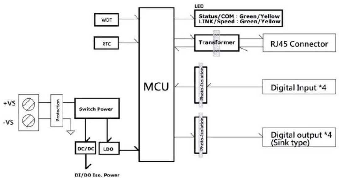
flowchart
graph TD
    A["+VS"] --> B["Protection"]
    C["-VS"] --> B
    B --> D["Switch Power"]
    D --> E["DC/DC"]
    D --> F["LDO"]
    E --> G["MCU"]
    F --> G
    G --> H["LED"]
    G --> I["Transformer"]
    I --> J["RS10"]
    I --> K["RJ45 Connector"]
    I --> L["Photo-Isolation"]
    L --> M["Digital Input *4"]
    L --> N["Digital output *4 (Sink type)"]
    G --> O["DI/DO Iso. Power"]
    H --> P["Status/COM: Green/Yellow"]
    H --> Q["LINK/Speed: Green/Yellow"]
Figure 2.8 WISE-4050/LAN Block Diagram
2.4 WISE-4060/LAN
2.4.1 I/O Specification
Digital Input
- Channel: 4
- Logic level
- Dry Contact 0: Open
1: Close to DI COM
- Wet Contact 0: 0\~3 V DC or -3\~0 V DC
1: 10\~30 V DC or -30\~-10 V DC (3 mA min.)
- Isolation: 3,000 V rms
– Supports 32-bit Counter Input Function (Maximum signal frequency 3 kHz)
- Keep/Discard Counter Value when Power-off
– Supports Frequency Input Function (Maximum frequency 3 kHz)
– Supports Inverted DI Status
Relay Output
– Channels: 4 (Form A)
- Contact Rating (Resistive Load)
-250 V _AC @ 5 A
-30 V _DC @ 3 A
- Relay On Time: 10 ms
- Relay Off Time: 5 ms
- Insulation Resistance: 1 GΩ min. @ 500 V _DC
– Dielectric Strength
-Between Contacts: 1000V_AC (1min)
-Between Coil to Contact: 3000V_AC (1min)
– Maximum Switching: 60 operations/minute
– Supports Pulse Output
– Supports High-to-Low and Low-to-High Delay Output
2.4.2 Application Wiring
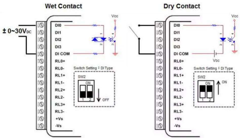
Figure 2.9 WISE-4060/LAN Digital Input Wiring Diagram
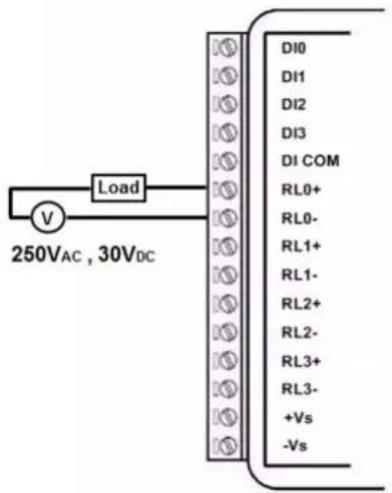
Figure 2.10 WISE-4060/LAN Relay Output Wiring Diagram
2.4.3 Pin Assignment
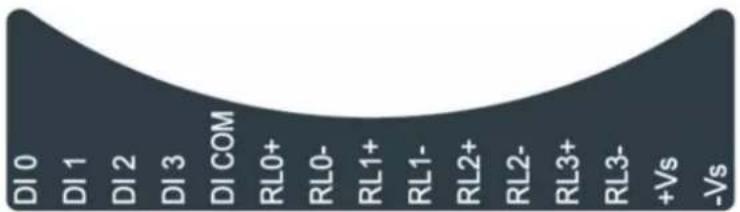
area
| Category | Value | |---|---| | DI0 | 1 | | DI1 | 2 | | DI2 | 3 | | DI3 | COM | | RI0+ | 4 | | RI0- | 5 | | RI1+ | 6 | | RI1- | 7 | | RI2+ | 8 | | RI2- | 9 | | RI3+ | 10 | | RI3- | 11 | | +Vs | 12 | | -Vs | 13 |Figure 2.11 WISE-4060/LAN Pin Assignment
2.4.4 Block Diagram
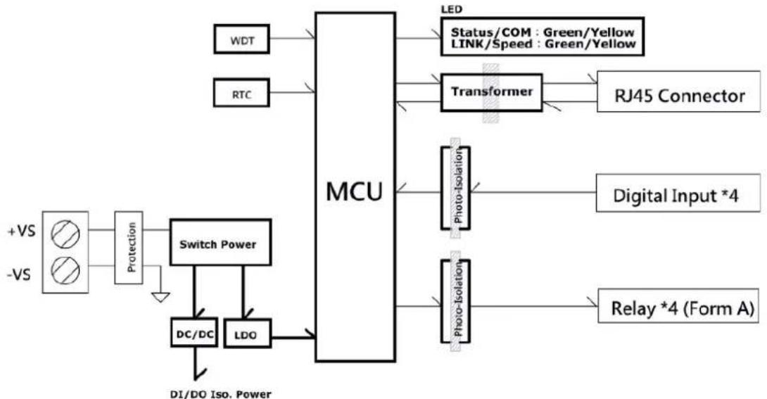
flowchart
graph TD
    A["+VS"] --> B["Protection"]
    C["-VS"] --> B
    B --> D["Switch Power"]
    D --> E["DC/DC"]
    D --> F["LDO"]
    E --> G["MCU"]
    F --> G
    G --> H["LED"]
    G --> I["Transformer"]
    I --> J["RJ45 Connector"]
    I --> K["Photo-Isolation"]
    K --> L["Digital Input *4"]
    K --> M["Relay *4 (Form A)"]
    D --> N["DI/DO Iso. Power"]
    N --> E
    style A fill:#f9f,stroke:#333
    style C fill:#f9f,stroke:#333
    style G fill:#ccf,stroke:#333
Figure 2.12 WISE-4060/LAN Block Diagram
2.5 WISE-4012E
2.5.1 I/O Specification
Voltage Input
- Channel: 2
- Resolution: 12-bit
– Sampling Rate: 10 Hz (Total) - Accuracy: ±0.1 V DC
- Input Range: 0\~10 V DC
- Input Impedance: 100 kΩ
– Supports Data Scaling and Averaging
Digital Input
- Channel: 2
- Logic level
—Dry Contact 0: Open
1: Close to GND
– Supports 32-bit Counter Input Function (Maximum signal frequency 3 kHz)
- Keep/Discard Counter Value when Power-off
– Supports Frequency Input Function (Maximum frequency 3 kHz)
– Supports Inverted DI Status
Relay Output
– Channels: 2 (Form A)
- Contact Rating
-120 V AC @ 0.5 A
-30 V DC @ 1A
- Relay On Time: 5 ms
- Relay Off Time: 6 ms
- Insulation Resistance: 1 GΩ min. @ 500 V DC
– Dielectric Strength
- Between Contacts: 1000VAC (1min)
- Between Coil to Contact: 1500V_AC (1min)
– Maximum Switching: 60 operations/minute
– Supports Pulse Output
– Supports High-to-Low and Low-to-High Delay Output
Note! The analog input channels of the WISE-4012E do not support 50/60 Hz noise rejection. The following methods can help to reduce noise:

■ Power up WISE-4012E by power bank
■ Supply sensor power by battery
■ Wiring V0- and V1- pin to GND pin
Note! The analog input channel of the WISE-4012E does not support inverted voltage protection, note that the input voltage should within 0\~10V _DC

2.5.2 Application Wiring
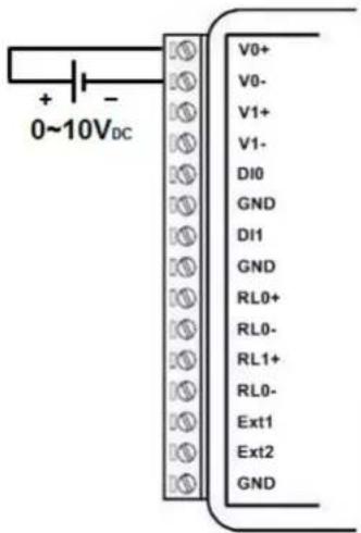
Figure 2.13 WISE-4012E Voltage Input Wiring Diagram
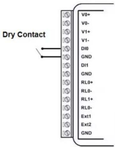
Figure 2.14 WISE-4012E Digital Input Wiring Diagram
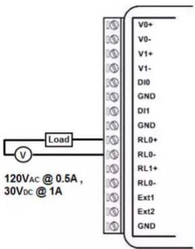
Figure 2.15 WISE-4012E Relay Output Wiring Diagram
2.5.3 Pin Assignment
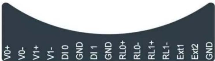
Figure 2.16 WISE-4012E Pin Assignment
2.5.4 Block Diagram
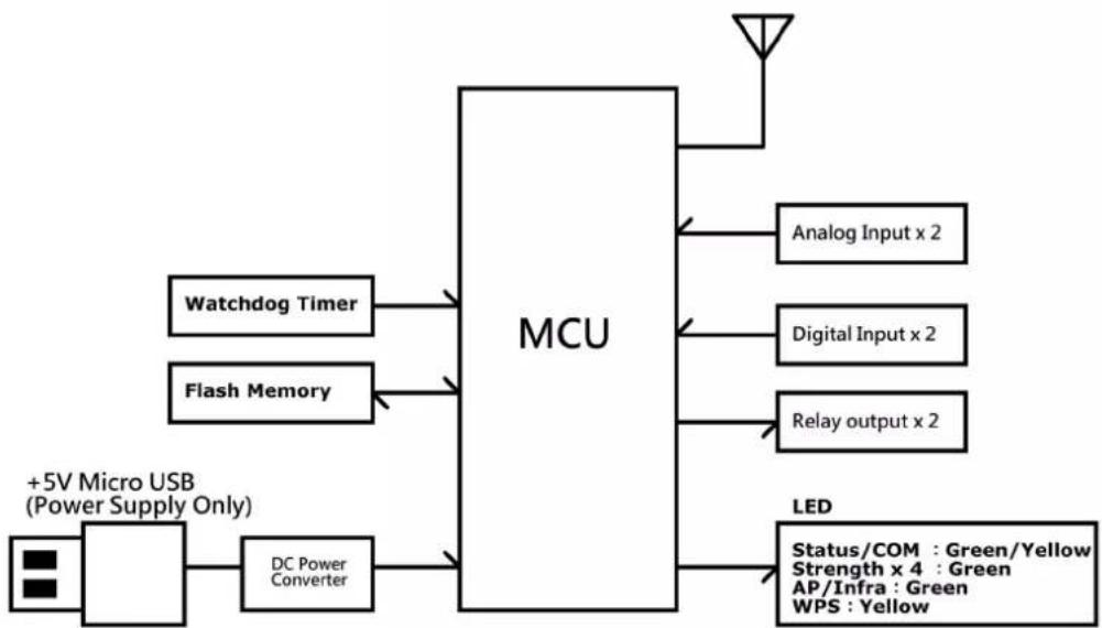
flowchart
graph TD
    A["+5V Micro USB (Power Supply Only)"] --> B["Watchdog Timer"]
    A --> C["Flash Memory"]
    B --> D["MCU"]
    C --> D
    D --> E["Analog Input x 2"]
    D --> F["Digital Input x 2"]
    D --> G["Relay output x 2"]
    H["DC Power Converter"] --> D
    I["LED"] --> J["Status/COM : Green/Yellow Strength x 4 : Green AP/Infra : Green WPS : Yellow"]
Figure 2.17 WISE-4012E Block Diagram
2.6 WISE-4012
2.6.1 I/O Specification
Universal Input
- Channel: 4
- Resolution: 16-bit
- Sampling Rate*
-Universal Input 10Hz (Total)
-Digital Input 2Hz (Per Channel)
- Accuracy
-Voltage ±0.1% of FSR
-Current ±0.2% of FSR**
- Input Type and Range
- Voltage Input ±150mV, ±500mV, ±1V, ±5V, ±10V, 0\~150mV, 0\~500mV, 0\~1V, 0\~5V, 0\~10V,
- Current Input 0\~20mA, 4\~20mA, ±20mA
- Digital Input 0: Open (Resistance > 1.5kΩ) (Dry Contact) 1: Close to GND (Resistance < 300 Ω)
- Input Impedance:
-Voltage >10M Ω
-Current 120 (Need external resistor**)
– Burn-out Detection for 4\~20 mA input range
– Supports Data Scaling and Averaging
* When the universal channel been configured as digital input, it will also share the sampling rate of analog input. And please be noted that the maximum sampling rate of digital input is 2Hz.
** For accuracy assurance in current mode, please use the 120 Ω precise resistors in the package list.
Digital Output
- Channel: 2
Open collector to 30 V, 400 mA max. for resistance load
- Inductive loads require an external diode to eliminate back-EMF when the DO is turned off
– Isolation: 3,000 Vrms - On Resistance (R _DS(ON) ): 0.7 Ω (max.) @ 200mA, 25°C, 5V
– Supports 5 kHz Pulse Output
– Supports High-to-Low and Low-to-High Delay Output
2.6.2 Application Wiring
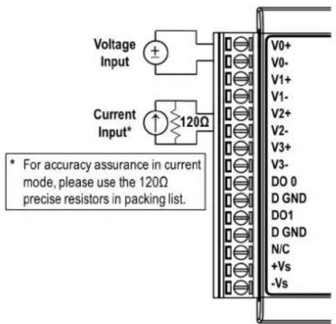
Figure 2.18 WISE-4012 Analog Input Wiring Diagram
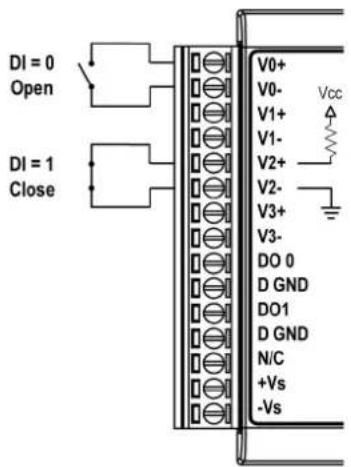
Figure 2.19 WISE-4012 Digital Input Wiring Diagram
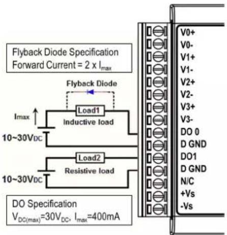
Figure 2.20 WISE-4012 Digital Output Wiring Diagram
2.6.3 Pin Assignment
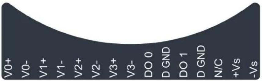
Figure 2.21 WISE-4012 Pin Assignment
2.6.4 Block Diagram
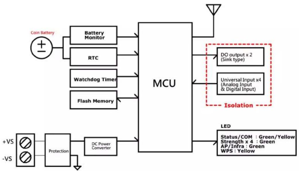
flowchart
graph TD
    A["Coin Battery"] --> B["Battery Monitor"]
    A --> C["RTC"]
    A --> D["Watchdog Timer"]
    A --> E["Flash Memory"]
    B --> F["MCU"]
    C --> F
    D --> F
    E --> F
    F --> G["DO output x 2 (Sink type)"]
    F --> H["Universal Input x4 (Analog Input & Digital Input)"]
    F --> I["Isolation"]
    J["+VS"] --> K["Protection"]
    L["-VS"] --> K
    K --> M["DC Power Converter"]
    M --> N["LED"]
    O["Status/COM : Green/Yellow Strength x 4 : Green AP/Infra : Green WPS : Yellow"] --> P["Signal"]
    style A fill:#f9f,stroke:#333
    style J fill:#ccf,stroke:#333
Figure 2.22 WISE-4012 Block Diagram
2.7 WISE-4050
2.7.1 I/O Specification
Digital Input
- Channel: 4
- Logic level
—Dry Contact 0: Open
1: Close to DI COM
-Wet Contact 0: 0\~3 V DC or -3\~0 V DC
1: 10\~30 V DC or -30\~-10 V DC (3 mA min.)
-All 4 channels should be configured to dry contact or wet contact in the same time
– Isolation: 3,000 V rms
– Supports 32-bit Counter Input Function (Maximum signal frequency 3 kHz)
- Keep/Discard Counter Value when Power-off
– Supports Frequency Input Function (Maximum frequency 3 kHz)
– Supports Inverted DI Status
Digital Output
- Channels: 4
- Open collector to 30 V, 500 mA max. for resistance load
- Inductive loads require an external diode to eliminate back-EMF when the DO is turned off
- Isolation: 3,000 V rms
- On Resistance (R _DS(ON) ): 0.7 Ω (max.) @ 500mA, 25°C
– Supports 5 kHz Pulse Output
– Supports High-to-Low and Low-to-High Delay Output
2.7.2 Application Wiring
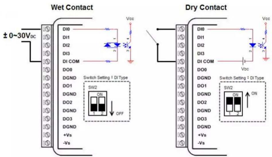
Figure 2.23 WISE-4050 Digital Input Wiring Diagram
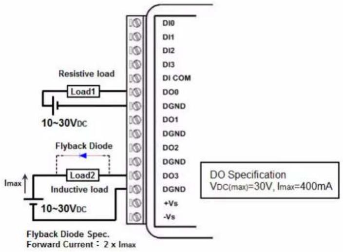
Figure 2.24 WISE-4050 Digital Output Wiring Diagram
2.7.3 Pin Assignment
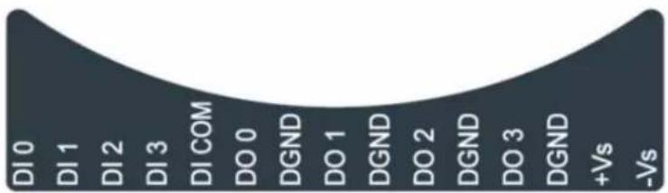
Figure 2.25 WISE-4050 Pin Assignment
2.7.4 Block Diagram
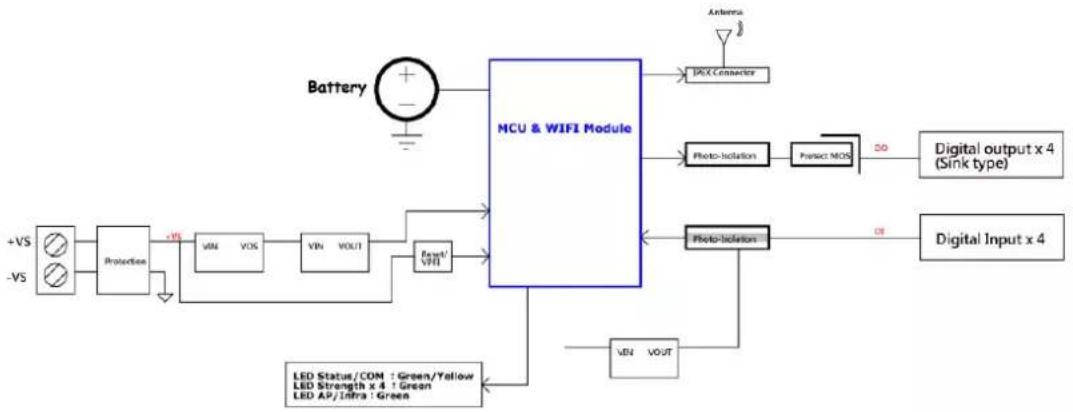
flowchart
graph TD
    A["Battery"] --> B["MCU & WIFI Module"]
    C["Protection"] --> D["+VS"]
    E["VIN"] --> F["VOS"]
    G["VOUT"] --> H["VIN"]
    I["Photo Isolation"] --> J["Photo Isolation"]
    K["LED Status/COM : Green/Yellow LED Strength x 4 : Green LED AP/Infra : Green"] --> L["VIN"]
    M["Photo Isolation"] --> N["Digital Output x 4 (Sink type)"]
    O["VOUT"] --> P["Digital Input x 4"]
    Q["Antenna"] --> R["PCC Connector"]
    S["Photo Isolation"] --> T["Photo Isolation"]
    U["Power/VOLT"] --> V["Power/VOLT"]
Figure 2.26 WISE-4050 Block Diagram
2.8 WISE-4051
2.8.1 I/O Specification
Digital Input
- Channel: 8
- Logic level
—Dry Contact 0: Open
1: Close to DI COM
-Wet Contact 0: 0\~3 V DC or -3\~0 V DC
1: 10\~30 V DC or -30\~-10 V DC (3 mA min.)
-Channel 0\~3 should be configured to dry contact or wet contact in the same time
-Channel 4\~7 should be configured to dry contact or wet contact in the same time
- Isolation: 3,000 V rms
– Supports 32-bit Counter Input Function (Maximum signal frequency 3 kHz) - Keep/Discard Counter Value when Power-off
– Supports Frequency Input Function (Maximum frequency 3 kHz)
– Supports Inverted DI Status
RS-485 Port
- Number of Ports: 1
- Port Connector: 3.5mm spacing plug-in screw terminal block (shared with I/O and power)
-Baud Rate (bps): 1200, 2400, 4800, 9600, 19200, 38400, 57600, 115200 - Data Bits:7, 8
- Stop Bits: 1, 2
- Parity: None, Odd, Even
- Flow Control: Auto flow control
- Signals: DATA+ and DATA-
- Protection: 15 kV ESD
– Supported Protocol:
-Modbus/RTU (Total 32 address by max. 8 instructions)
2.8.2 Application Wiring
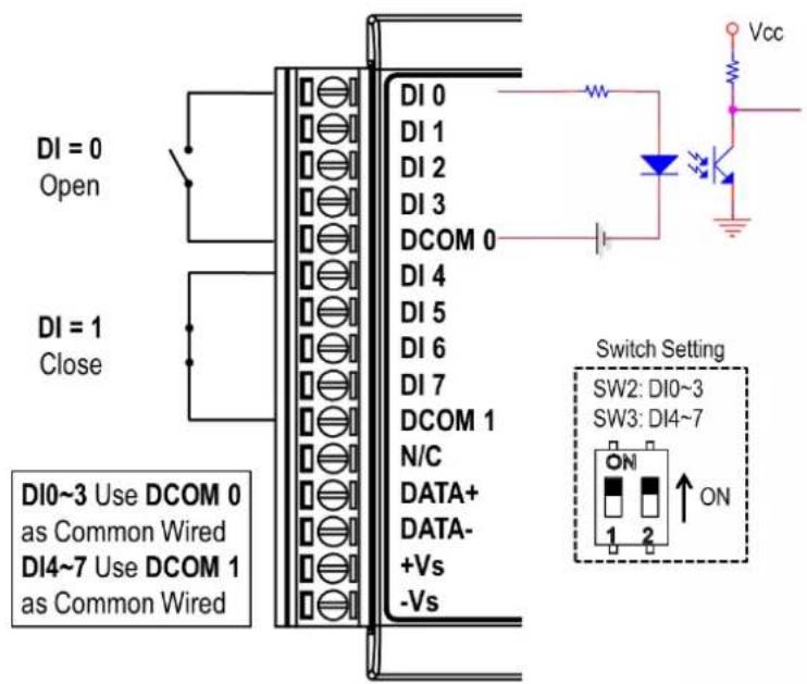
Figure 2.27 WISE-4051 Digital Input Dry Contact Wiring Diagram
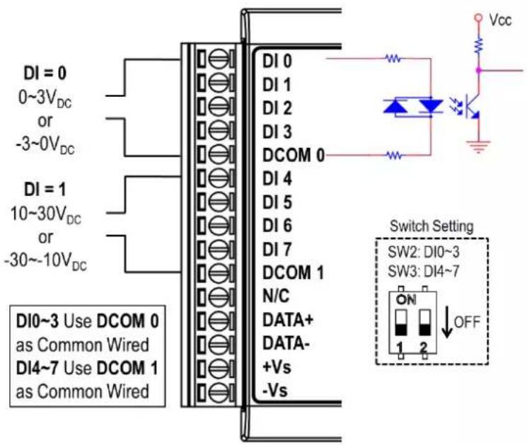
Figure 2.28 WISE-4051 Digital Input Wet Contact Wiring Diagram
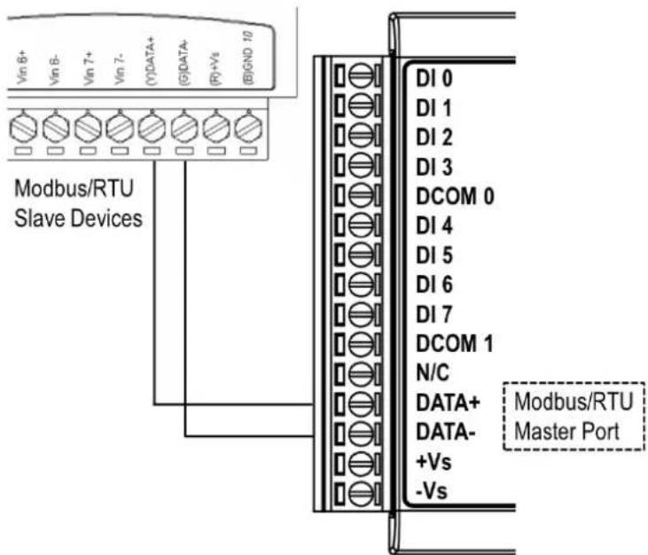
Figure 2.29 RS-485 Port Wiring Diagram
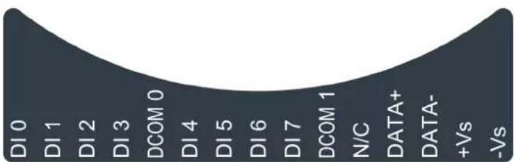
2.8.3 Pin Assignment
area
| Category | Value | |---|---| | DI 0 | High | | DI 1 | Medium | | DI 2 | Low | | DI 3 | Medium | | DCOM 0 | Low | | DI 4 | Low | | DI 5 | Low | | DI 6 | Low | | DI 7 | Low | | DCOM 1 | Medium | | N/C | Medium | | DATA+ | Medium | | DATA- | Medium | | +Vs | Medium | | -Vs | Medium |Figure 2.30 WISE-4051 Pin Assignment
2.8.4 Block Diagram
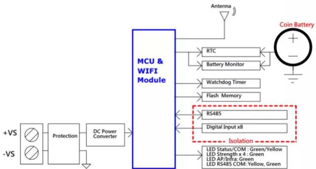
flowchart
graph LR
    A["+VS"] --> B["Protection"]
    C["-VS"] --> B
    B --> D["DC Power Converter"]
    D --> E["MCU & WIFI Module"]
    E --> F["Antenna"]
    E --> G["RTC"]
    E --> H["Battery Monitor"]
    E --> I["Watchdog Timer"]
    E --> J["Flash Memory"]
    E --> K["RS485"]
    E --> L["Digital Input x8"]
    E --> M["Isolation"]
    M --> N["LED Status/COM : Green/Yellow\nLED Strength x 4 : Green\nLED AP/Infra: Green\nLED RS485 COM: Yellow, Green"]
    G --> O["Coin Battery"]
Figure 2.31 WISE-4051 Block Diagram
2.9 WISE-4060
2.9.1 I/O Specification
Digital Input
- Channel: 4
- Logic level
-Dry Contact 0: Open 1: Close to DI COM -Wet Contact 0: 0\~3 V DC or -3\~0 V DC 1: 10\~30 V DC or -30\~-10 V DC (3 mA min.)
- Isolation: 3,000 V rms
– Supports 32-bit Counter Input Function (Maximum signal frequency 3 kHz) - Keep/Discard Counter Value when Power-off
– Supports Frequency Input Function (Maximum frequency 3 kHz)
– Supports Inverted DI Status
Relay Output
- Channels: 4 (Form A)
- Contact Rating (Resistive Load)
-250 V _AC @ 5 A
-30 V _DC @ 3 A
– Relay On Time: 10 ms
- Relay Off Time: 5 ms
- Insulation Resistance: 1 GΩ min. @ 500 V _DC
– Dielectric Strength
-Between Contacts: 1000V_AC (1min)
—Between Coil to Contact: 3000 V _AC (1min)
– Maximum Switching: 60 operations/minute
– Supports Pulse Output
– Supports High-to-Low and Low-to-High Delay Output
2.9.2 Application Wiring
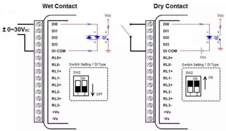
Figure 2.32 WISE-4060 Digital Input Wiring Diagram
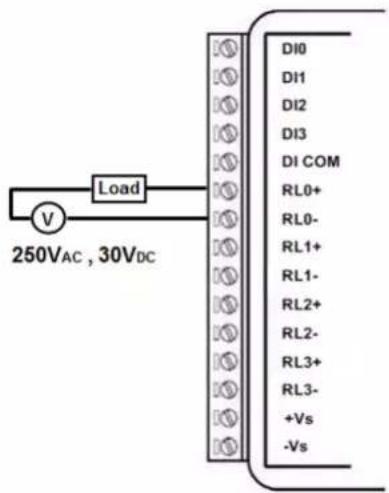
Figure 2.33 WISE-4060 Relay Output Wiring Diagram
2.9.3 Pin Assignment
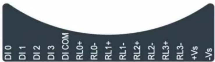
Figure 2.34 WISE-4060 Pin Assignment
2.9.4 Block Diagram
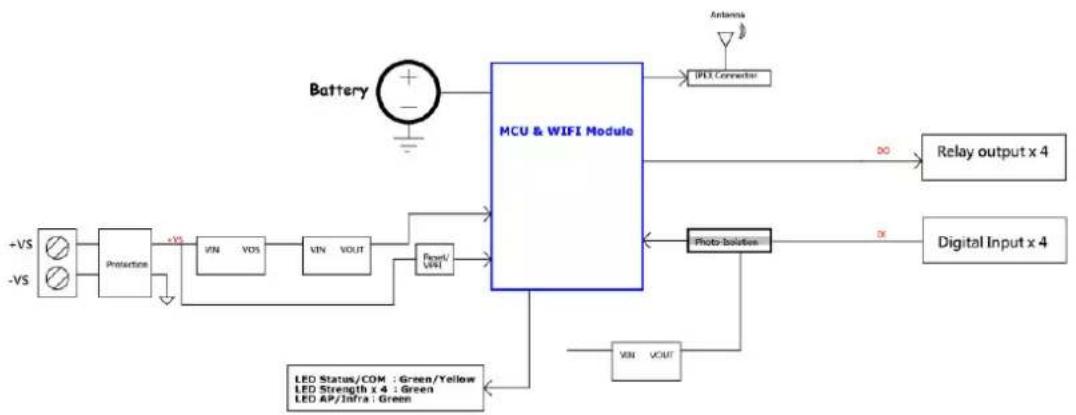
flowchart
graph TD
    A["+VS"] --> B["Protection"]
    C["-VS"] --> B
    B --> D["+VS"]
    D --> E["VIN"]
    E --> F["VOS"]
    F --> G["VIN"]
    G --> H["VOUT"]
    H --> I["Power/VIN"]
    I --> J["MCU & WIFI Module"]
    K["Battery"] --> L["+"]
    L --> M["Antenna"]
    N["IPLEX Connector"] --> O["Relay output x 4"]
    P["Photo Solution"] --> Q["Digital Input x 4"]
    R["VIN"] --> S["LED Status/COM : Green/Yellow\nLED Strength x 4 : Green\nLED AP/Inf/a : Green"] --> J
    T["VOUT"] --> U["Photely Solution"]
    V["∞"] --> W["Relay output x 4"]
Figure 2.35 WISE-4060 Block Diagram
Chapter 3
Hardware Installation
3.1 Interface Introduction
3.2 Mounting
WISE-4000 modules are designed as compact units and are allowed to be installed in the field site under the following methods.
3.2.1 DIN-Rail Mounting
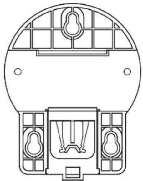
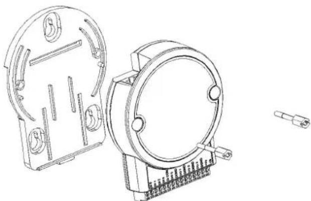
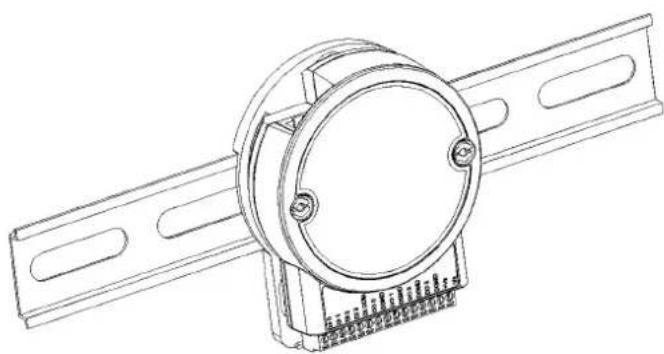
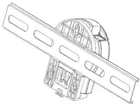
The WISE-4000 module can also be fixed to the cabinet by using mounting rails. You need to assemble the DIN rail adapter to WISE-4000 module with flathead screw driver as below. When the module is mounted on a rail, you may also consider using end brackets at each end of the rail to keep the module from sliding horizontally along the rail.
natural_image
Technical line drawing of a circular mechanical component with internal grid structure (no text or symbols)Figure 3.1 Mounting Kit Back View
natural_image
Technical line drawing of two mechanical components with mounting holes and a separate terminal pin (no text or symbols)Figure 3.2 Installing the Mounting Kit for a DIN-Rail
natural_image
Technical line drawing of a mechanical component with mounting brackets and a central circular housing (no text or symbols)Figure 3.3 Mounting on the DIN-Rail
natural_image
Technical line drawing of a mechanical assembly with internal components (no text or symbols)Figure 3.4 Rear View of DIN-Rail Mounting
3.2.2 Wall Mounting
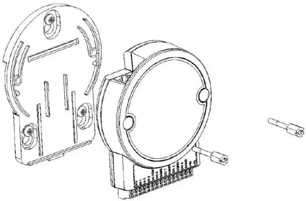
Each WISE-4000 module is packed with a plastic wall mounting bracket. User can refer the bracket dimension and assembling figure to configure an optimal placement in a wall, panel, or cabinet.
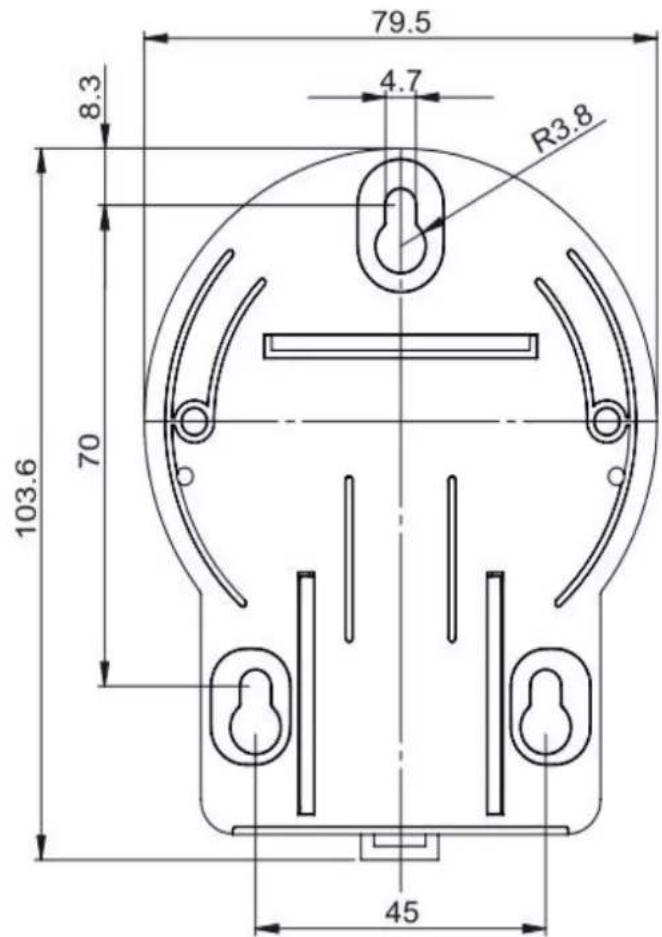
Figure 3.5 Mounting Kit Dimensions
natural_image
Technical line drawing of two mechanical components with mounting holes and a connector pin (no text or symbols)Figure 3.6 Wall Mounting
natural_image
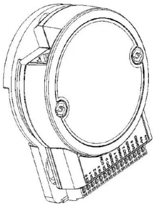
Technical line drawing of a mechanical component with no visible text or symbolsFigure 3.7 Wall Mounting Finished
3.2.3 Stack Mounting
natural_image
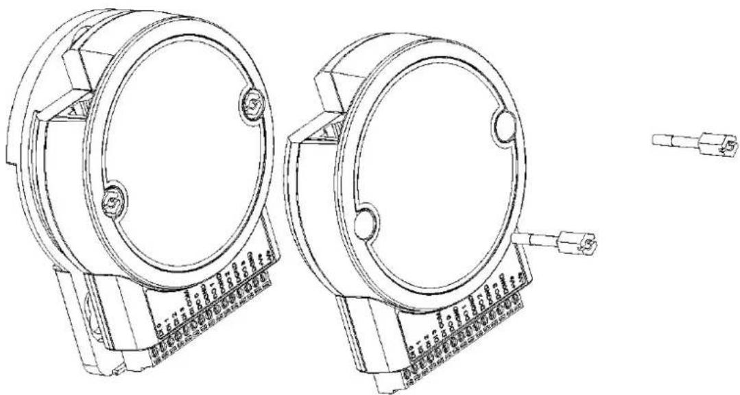
Technical line drawing of two circular mechanical components with mounting holes and a separate terminal pin (no text or symbols present)Figure 3.8 Stack Mounting
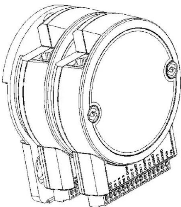
natural_image
Technical line drawing of a cylindrical mechanical component with mounting base (no text or symbols)Figure 3.9 Finished Stack Mounting
3.3 Wiring & Connections
This section introduces basic information on wiring the power supply, I/O units, and Ethernet connection.
3.3.1 Power Supply Wiring (Not for WISE-4012E)
The system of WISE-4000 is designed for a standard industrial unregulated 24 V DC power supply. For further application, it can also accept +10 to +30 V DC of power input, 200mV peak to peak of power ripple, and the immediate ripple voltage should be maintained between +10 and +30 V _DC .
Screw terminals +Vs and -Vs are for power supply wiring
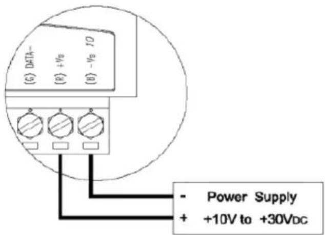
Figure 3.10 Power Supply Wiring
Note! The wires used should be at least 2 mm.

3.3.2 USB Power (WISE-4012E Only)
The system of WISE-4012E IoT Developer Kit is designed for a standard Micro-B USB 5V DC power supply. Use the provided USB power cable to power up the module. Insert the Micro-B USB end to the USB port on the side of the module, and insert another end to Type-A 5V DC USB port such as a PC, notebook, USB power adapter, USB power bank.
Note!The wider or flared part of the USB Micro-B connector is at the front side

of the module, please make sure the direction of the cable before inserting it into the module to prevent the damage to the USB port.
Some USB power banks will automatically switch off, in this case, use a standard USB power instead.
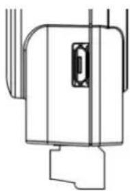
natural_image
Pure technical line drawing of a mechanical component without any text, numbers, or symbolsFigure 3.11 USB Power Supply Wiring
3.3.3 I/O Units
The system uses a plug-in screw terminal block for the interface between I/O modules and field devices. The following information must be considered when connecting electrical devices to I/O modules.
- The terminal block accepts wires from 0.5 mm to 2.5 mm.
- Always use a continuous length of wire. Do not combine wires.
- Use the shortest possible wire length.
- Use wire trays for routing where possible.
- Avoid running wires near high-energy wiring.
- Avoid running input wiring in close proximity to output wiring.
- Avoid creating sharp bends in the wires.
Chapter 4
System Configuration
4.1 Connection
- Plug a DC power source into the +Vs, -Vs pin of WISE module to turn the power on, or plug in the USB power cable for the WISE-4012E.
- For WISE-4000/LAN Series, connect your computer to Ethernet port of WISE module with RJ-45 cross-over Ethernet cable, and configure the IP address of your computer as same IP domain as default IP address of module: 10.0.0.1. Or the wireless router can be used for configure the WISE-4000/LAN Series by mobile devices or computer with wireless adapter.
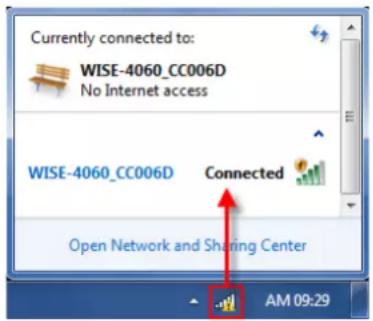
- For WISE-4000 Wireless Series, the default operation mode in normal mode is AP Mode, or you can change position 1 of SW1 to OFF as in Section 1.5, to setting the module as Initial Mode, then module must be AP Mode. Now the module can be searched by mobile devices or wireless adapter of computer with SSID: WISE-4xxx_MACAddress. Click the SSID to connect the module in AP Mode, WISE module will auto assign the IP address for mobile devices or computer.
4.2 Configure WISE Using the Web Interface
4.2.1 System Requirements
WISE-4000 module is developed by public HTML 5 base, but for detailed indication and data transmission mode may be different on Web page of the operating system.
For mobile devices, the minimum requirement of web browsers as below:
■ Safari 6 in Apple iOS
■ Web Browser in Google Android 4.0 (Ice Cream Sandwich)
■ Chrome in Google Android 4.0 (Ice Cream Sandwich)
| Mobile Browse Chrome Android Safari | |||
| Configuration Y Y Y | |||
| File Upload N N N | |||
| Data Log Chart Y Y Y | |||
| Data Log Export N N N | |||
For PC platforms, the minimum requirement of web browsers as below:
■ Internet Explorer (version 11)
■ Google Chrome (version 30)
■ Mozilla Firefox (version 25)
| Mobile Browse | Chrome | Firefox | Safari | IE11 | IE10 | IE9 |
| Configuration | Y | Y | Y | Y | Y | Y |
| File Upload | Y | Y | N | Y | N | N |
| Data Log Chart | Y | Y | Y | Y | Y | N |
| Data Log Export | Y | Y | N | N | N | N |
4.2.2 List of WISE-4000 Default Ethernet Ports
| Application Protocol | Port Note | ||
| WebServer TCP 80 Configurable | |||
| Modbus Server TCP 502 - | |||
| Search Engine | UDP | 5048 | - |
| SNTP Client | UDP | - | Randomly |
4.2.3 Factory Default Settings
WISE-4000/LAN Series
■ Operation Mode: Normal Mode
IP Mode: Static IP Address
Default IP: 10.0.0.1
■ Subnet Mask: 255.0.0.0
■ Default Gateway: 0.0.0.0
■ Default Connection Timeout: 720 second
HTTP Port: 80
WISE-4000 Wireless Series
■ Operation Mode: Normal Mode
■ Wireless Mode: AP Mode
IP Mode: Static IP Address
Default IP: 192.168.1.1
Subnet Mask: 255.255.255.0
■ Default Gateway: 192.168.1.1
DHCP Server: Enabled
■ Default Connection Timeout: 720 second
HTTP Port: 80
4.2.4 Module Authorization
| Account | Default Password | Access Ability |
| root | 00000000 | All the privileges |
| admin | 00000000 | All the privileges except access control configuration |
| user | 00000000 | View module status only, not allow to do configuration |
4.2.5 Operation Mode
The operation mode can be configured by switch SW1 on the back of module. Please refer to previous chapter for the detail of configuring SW1.
| Mode | WISE-4000/LAN Series | WISE-4000 Wireless Series |
| Initial Mode | Fixed IP address: 10.0.0.1 | Fixed IP address: 192.168.1.1Fixed Wi-Fi Mode: AP Mode |
| Normal Mode | Default IP address: 10.0.0.1 | Default IP address: 192.168.1.1Default Wi-Fi Mode: AP Mode |
4.2.6 Using a Browser to Configure the Module
- Configure URL: http://IP_address/config
Default URL: WISE-4000/LAN Series: http://10.0.0.1/config WISE-4000 Wireless Series: http://192.168.1.1/config
Configuration Steps
| Login Web Configuration Page | |
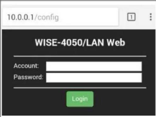 | 1. Wirelessly connect your smart phone to your local Ethernet network and open the browser of your smart phone.2. Enter IP address of module with "/config", for example, the default URL: http://10.0.0.1/config or http://192.168.1.1/config3. Then you will see the login page, please enter the account and password, then click Login button |
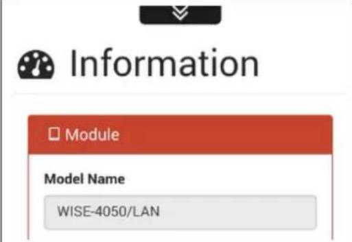 | 4. After login you will see the configura-tion web page |
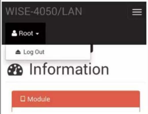 | 5. Scroll down the tab, you can change the login user here |
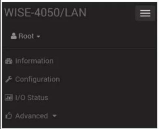 | 6. Click the button on the top, you can switch to other pages |
System Information
In the information page, you can see the dashboard: module detail, network setting, and module information, including the firmware version.
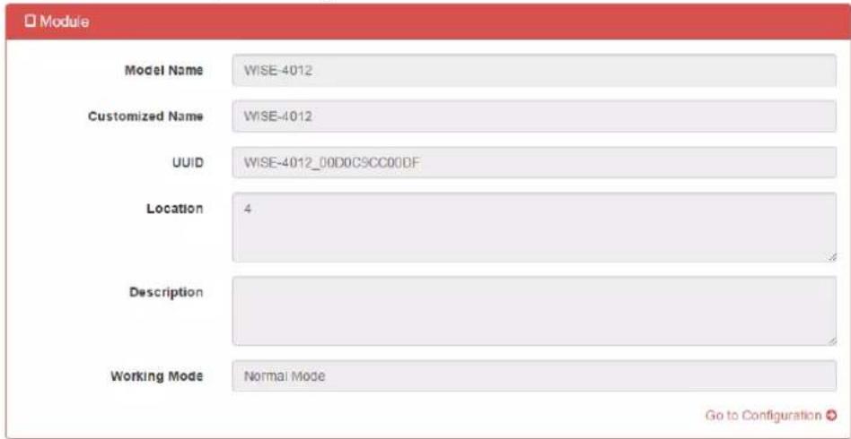
Module
Here you can see the naming of the module and related information. Click "Go to Configuration" to perform the configuration.
- Model Name: Indicates the WISE model
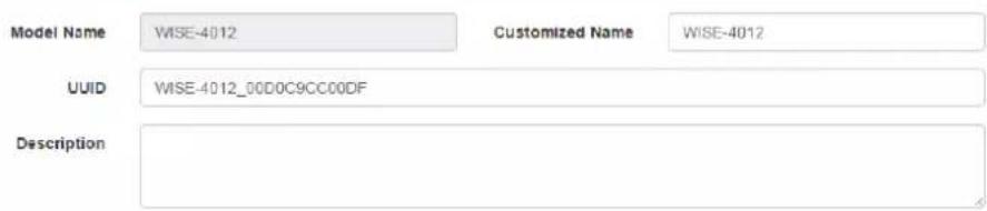
- Customized Name / UUID: Model name and UUID of the module, the default UUID is the combination of model name and the MAC address. It can be renamed.
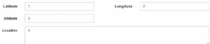
- Location Information: You can note the location of the module
— Description: You can add comments on this module for easier recognition. - Working Mode: Refer to 4.2.5 for Operation Mode
Module Information
Location Information
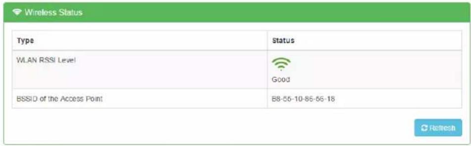
Wireless Status
For the WISE-4000 Wireless Series, users can check the WLAN RSSI Level to know the signal quality in Wireless Status field. And it also shows the MAC ID of the client device.
If the module is in AP Mode, the WLAN RSSI Level and Refresh button will not be shown.
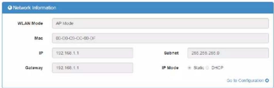
■ Network Information
For the WISE-4000 Wireless Series, WLAN Mode (AP Mode / Infrastructure) will be shown in Network Information. Here is an overview of the entire network configuration. To configure the network configuration, click "Go to Configuration".
■ Module Information
Here you can check the model name and the module description of the module. The firmware version will also been shown here. At the end of the configuration web page, you can see the version of the configuration web page. For normal release module, the version of configuration web page will increase with the firmware version, these have been updated at the same time.
To update the firmware version, go the "Firmware Version" section.
| Module Name | Module Description | Firmware Description |
| WISE-4012 | 2-channels digital output, 4-channels universal input | Fw:A0.91 B00, Bootloader:A0.90 B00 |

■ Network Configuration
- WLAN
AP Mode
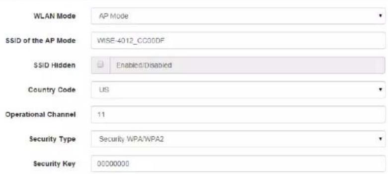
When using the module in AP mode, users can configure the SSID and also decide how the WISE module works as an AP, including the security.
The "AP Mode IP Settings" is fixed and does not allow user to make their own changes.
WLAN Settings
AP Mode IP Settings

◆ Infrastructure Mode
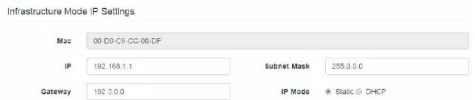
When using the module in "Infrastructure Mode", users need to enter the SSID of the Access Point (AP) the WISE is going to access, and configure the security from here. WISE-4000 wireless modules provide a Second AP Setting, this is an optional setting for the WISE module to access another AP automatically. If you do not have a Second AP, you can leave the SSID blank.
After configuring the AP that the WISE module going to access, the IP address also needs to be defined in the Infrastructure-Network.
WLAN Settings

First AP Settings
SSID of the Access Point
Twifi
Security Type
Security Open

-LAN
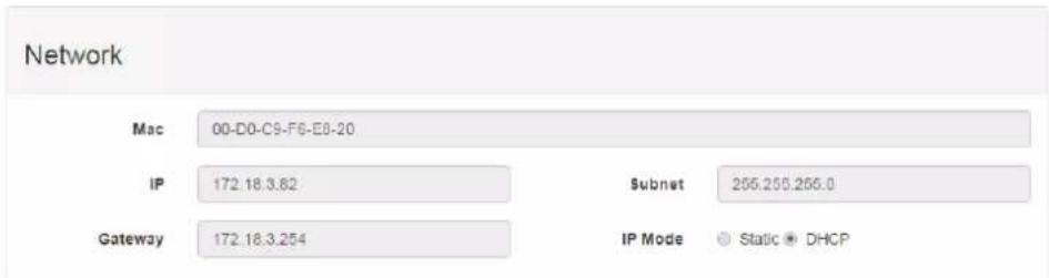
For WISE-4000/LAN wired module, you can select the Connection mode as DHCP or Static IP and configure the IP address, Subnet address, and Default gateway.
IO Status
- UI
For the WISE-4012, there are four universal input channels which can be configured as Analog Input (AI) or Digital Input (DI). Before using the universal input channels, you need to configure the universal input channels to be AI or DI here.
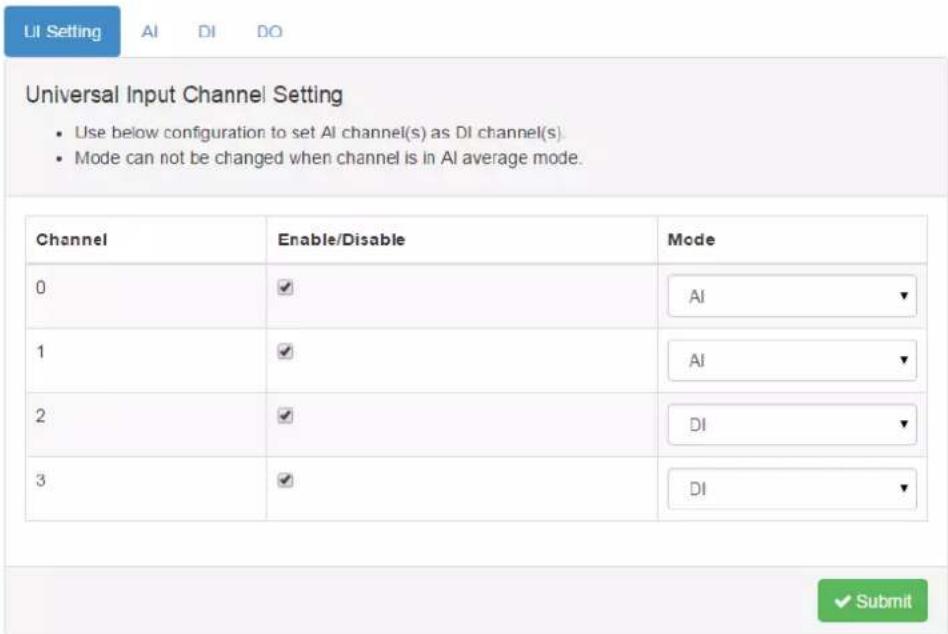
- AI
For the AI channel, the Current/Max/Min status will be shown in the status page, which includes the input range. The current status shows the latest AI value, and also the input range. The average value, which will be introduced in following pages, show the average value of selected channels.
The Max/Min status shows historical maximum or minimum value, you can reset the value by pressing "Reset".
![DI Setting AI DI DO Status Configuration Trend Status Current Max Min Channel: 0 Range: +/- 10 V Value: -0.0041 V Low Alarm Status: Clear High Alarm Status: Clear Ch Range Value[Eq] Value[Hex] Value[Dec] 0 +/- 10 V -0.0041 V 7FF2 32754 1 +/- 10 V -0.0041 V 7FF2 32754](/content/2026/05/895695/images/7f9faf8f0a6efee8dba36c126a6f5db17045582acb4fd515e134ff1102857737.jpg)
![DI Setting AI DI DO Status Configuration Trend Status Current Max Min Channel: 0 Range: +/- 10 V Value: 0.0090 V Reset Value: Reset Ch Range Value[ Eg ] Value[ Hex ] Value[ Dec ] 0 +/- 10 V 0.0090 V 801D 32797 1 +/- 10 V -0.0050 V 7FEF 32751](/content/2026/05/895695/images/498e8456d570014cf5f433ca20faead2748d4a9990ed46e3f19dcee7485a1210.jpg)
Input Range
For the AI channel which supports more than input range, you can configure the channel setting in "AI/Configuration/Channel Settings".
- Channel Mask
You can disable the AI channel to increase the sampling rate of other enabled channels in "Channel Mask".
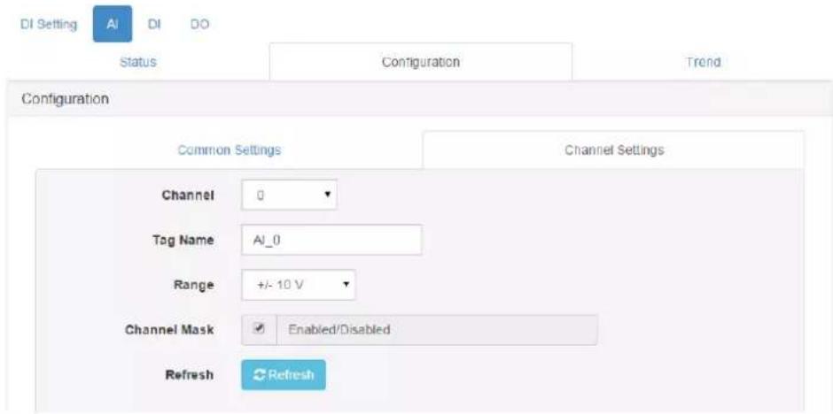
♦ Scaling Function
There are two types of scaling function for AI channels:
1. Input Signal Scaling - Scaling the Input Range
This is for scaling the analog input range within the configured input range, so that the Modbus value can fit the entire range. For example, Ch0 of WISE-4012 had been configured with an input range of 0\~5V, but the full range of signal from sensors is 1\~5V. If users do not use the Input Signal Scaling function, the 1V will be presented as 13107 in Modbus, 5V will be presented as 65535. But after Input Signal Scaling, 1V will be presented as 0 in Modbus, and 5V will still be presented as 65535.
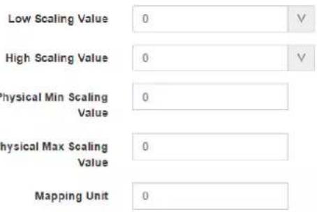
If you would like to apply the function in the previous example, enter 1 in "Low Scaling Value", and enter 5 in "High Scaling Value".
Note! The function only increases the resolution of Modbus data, but the accuracy still depends on the original input range before scaling. Furthermore, in the previous example, if the 0\~10V input range been used for scaling to 1\~5V, it may have a lower accuracy compared to using 0\~5V.
For values which are going to be configured for scaling the input range, note that the "Low Scaling Value" should be lower than "High Scaling Value".
2. Physical Value Scaling - Scaling the Output Data
Further to scaling the input range of the analog input channel, the output data can also be scaled. After the function has been applied, it would be easier to read the Modbus value in the engineering unit. For example, a temperature sensor output 0\~10 V which shows 0\~100°C. It would be better to read 0\~100 in Modbus with floating data format.
In the previous case, you can configure the "Physical Min Scaling Value" and "Low Scaling Value" as 0, which shows the input voltage 0 V as physical value 0°C; and configure the "Physical Max Scaling Value" as 100 and "High Scaling Value" as 10, which shows the input voltage 10V as physical value 100°C.
Note! The function is helping the data be more readable, but the accuracy still depends on the original input range before scaling and also depends on the sensor's accuracy.

For the values which are going to be configured for scaling the output data. For users using RESTful Web API Mapping Unit, can be configured here for further use.
◆ High/Low Alarm
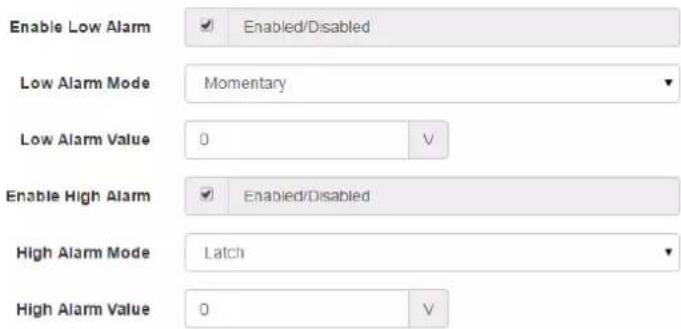
For an AI module with digital or relay output functions featuring a built-in alarm function. When the analog input value is higher than the high alarm value, or lower than the low alarm value, an alarm condition occurs. Then the alarm status will be activated to logic high. The alarm status ia shown in the status page of AI as alarm status LED display, when the alarm condition occurs, the Alarm status LED display will be lit.
The specified digital output channel will generate a logic high value if you build the mapping relationship between alarms and DO channel in the DO mapping area. You can map the DO channel referring to AI Alarm section of DO configuration. The High/Low Alarm status LED in AI status page can be cleared by clicking "Clear".
This page is for enabling and configuring the alarm. There are two alarm modes:
- Latch: Once the alarm occurs, the alarm status will be activated to logic high level and will keep the value until the alarm is manually cleared. Before the value is cleared, the Alarm status LED will be continuously lit. For an AI module with digital or relay output functions, the specific output channel (chosen in the DO AI Alarm configuration page) will continuously generate logic high value. You can clear the alarm by clicking the "Clear" button in the AI status page.
- Momentary: The alarm status will dynamically change depending on the alarm condition. If the alarm occurs, the alarm status will be logic high. If the alarm condition disappears, the alarm status will be logic low. So not only will the Alarm status LED be lit, in the web page the specific digital output channel value will change depending on the alarm condition.
After you choose the alarm mode for high alarm or low alarm, you can define the high alarm value or low alarm value by entering the value in Alarm limit text box.
Burnout Detection
The Burnout Detection function, or open-wired function, is designed for 4\~20mA input range or temperature input range. For the WISE-4012, the burnout signal is activated when the current is less than 3mA. The Modbus flag indicates that the wire of the sensor connected to the channel has burned out. You can also check the Modbus address of AI Channel Status for detail.
When a burnout situation had been detected, the AI value can be shown in "Up scale" which is FFFF(HEX), or "Down scale" which is 0. You can configure this in "Burnout Detection Mode".
Sampling Rate
For models which support more than one sampling rate, you can configure the sampling rate here. For low sampling rate mode, the AI channel would have better noise rejection ability. For the high sampling rate mode, the noise will allow easier coupling to the signal.
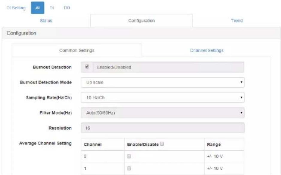
◆ Average Channel Setting
To reduce the data amount, some users don't need the detailed value of each channel but the average value of the selected channel. When the channel is enabled, the values will be averaged in 16-bit integer data, and can be shown or read as another channel.
Calibration
WISE analog input modules support internal reference calibration function, before using the calibration function, you can also try to reset the module to the default factory settings for troubleshooting, or if the calibration process had not succeeded, you can reset the module to the default factory calibration parameters.
Click "Calibration" and follow the instructions to calibrate the AI channels.
| Average Channel Setting | Channel | Enable/Disable | Range |
| 0 | ☐ | +/- 10 V | |
| 1 | ☐ | +/- 10 V | |
| 2 | ☐ | +/- 10 V | |
| 3 | ☐ | +/- 10 V | |
| Calibration | Calibration | ||
AI Trend
Here you can instantly check the analog input trend of each channel. The function is useful when testing the connection and variety between WISE and sensors.
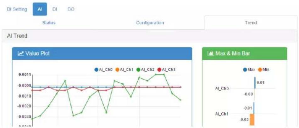
line
| Series | Value | | -------- | --------- | | AI_Ch0 | 0.001 | | AI_Ch1 | -0.03 |- DI
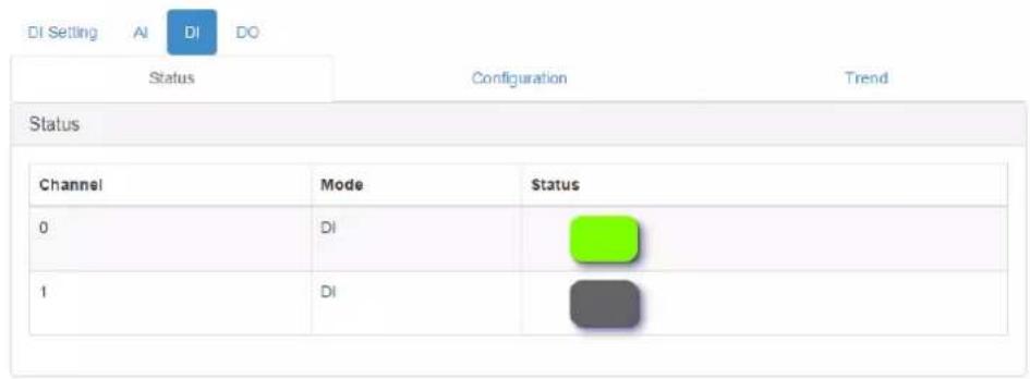
You can see the value of all digital input channels by the related LED display in this page. When DI status is a logical high, the LED will be green. If the status is a logical low, the LED will be grey.
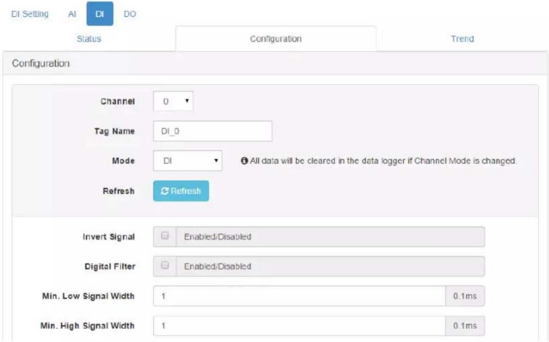
♦ Invert Signal
WISE digital input channels support Invert DI Status function, there will be an Invert Signal check box in the configuration page. Click the check box to enable/disable the function.
◆Digital Filter
Digital input channels support digital filters, these can be enabled or disabled by clicking the Digital Filter check box. If you enable the filter, you can define the minimum acceptable signal width by the Min. Low Signal Width and Min. High Signal Width text box. (Unit: 0.1ms) The high frequency noise will be removed by this filter.
◆ Counter Mode
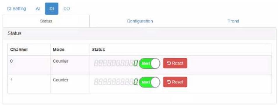
When you choose Counter mode, one counter will count the pulse number of the digital signal from the selected channel, and then record the count number in the register. In the DI Status page, the current count value of the selected channel is displayed by the Counter value text box. Start or stop the counter by switching the Start/Stop switch next to the Counter value. Reset the counter (the value in the register will be initialized to the startup value, default to be zero) by clicking the Reset button. Preset the Startup Value in the text box. When you reset the counter value, either by the reset button in the status page or by a command, the value will be reset to the Startup Value. The default value of the Startup Value is zero.
Like the DI mode, you can enable/disable the Invert Signal function and Digital Filter in the configuration page. The operation is the same. If you enable Keep Last Value, when the digital module been powered off, the last counter value will be kept in the register. When the module powers on, the counter will continuously count from that value. Without this function, when the module powers off, the counter will reset and the count value in the register will be zero.

- Low to High Latch
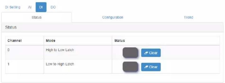
When you choose Low to High Latch mode, once the digital input channel detects logic level changes from low to high, the logic status will be kept as logic high. The logic status will remain the logic high, until you clear the latch manually. The logic status will return to logic low. The logic status can be seen by the Latch status LED display in the DI Status page. Clear the latch by clicking the Clear button. Enable/disable the Invert Status function in the configuration page.
- High to Low Latch
When you choose High to Low Latch mode, once the digital input channel detects logic level changes from high to low, the logic status will be kept as high. The logic status will remain high, until you clear latch manually. Then the logic status will return to low. The logic status can be seen by the Latch status LED display in the DI Status page. Clear the latch by clicking the Clear button. Enable/disable the Invert Status function in the configuration page.
◆ Frequency
For pure DI channels, not including the DI function of the WISE-4012, WISE modules support frequency mode. WISE module will calculate the frequency value of the digital input signal from the selected channel. The frequency value will be displayed in the Frequency value text box in the DI Status page.
-DO
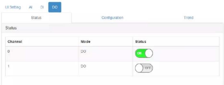
You also can control the values of all digital output channels by the status switch. The color of the switches will display current value of that digital output channel.
◆Fail Safe Value (FSV)
When the communication between the host controller and WISE digital modules is broken, the digital output channel can generate a predefined value (this value is called the fail safe value). If the FSV checkbox is checked, the module will set the output channel to logic high when WDT times-out. If the FSV checkbox is unchecked, the module will set the output channel to logic low when WDT times-out.
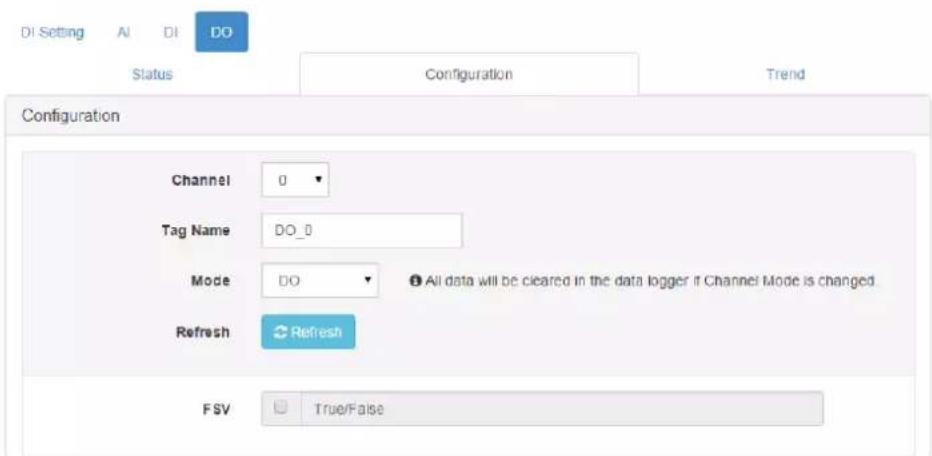
To decide whether to enable the FSV function triggered by communication with the WDT, go to General Configuration and enable the FSV function for all the module's output channels.
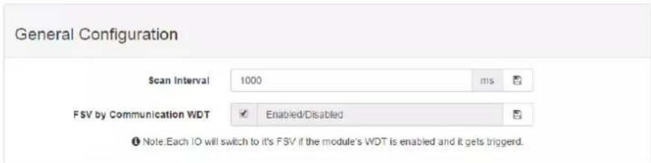
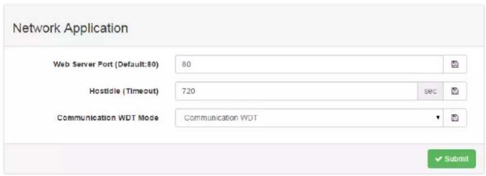
To decide the time period to trigger the communication WDT, go to Network Application to enable the Communication WDT Mode as Communication WDT first, and then configure the Host Idle (Timeout). (Unit: second) The default host idle time is 720 seconds.
♦ Pulse Output
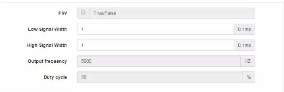
After you choose the Pulse Output mode, the selected digital output channel can generate continuous pulse train or finite pulses. You can define the pulse width by entering into the Low Signal Width and High Signal Width text box in the configuration page. (Unit: 0.1 ms) The frequency and duty cycle of the pulse output signal will be calculated automatically and displayed by the Output frequency and Duty cycle text box.
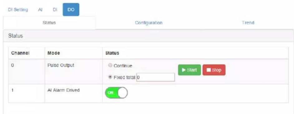
Then choose whether to generate a continuous pulse train or finite pulses by selecting the Continuous (for pulse train) or the Fixed total (for finite pulses). The text box on the right of the Fixed total button is used to define how many pulses you want to generate. After selecting pulse output mode, click the Start or Stop button to generate or to stop the pulse output.
- Low to High Delay
Choosing Low to High Delay mode, is almost the same as choosing DO mode. The only difference is that there will be certain time delays when the output value changes from logic low to logic high. Define the delay time by entering its value into the Delay Time text box in the configuration page. Control the digital output value using the DO button and seeing its current value by the DO status LED display in the DO Status page.
- High to Low Delay
Choosing High to Low Delay mode, is almost the same as choosing DO mode. The only difference is that there will be certain time delay when the output value changes from logic high to logic low. Define the delay time by entering its value into the Delay Time text box in the configuration page. Control the digital output value using the DO button and seeing its current value by the DO status LED display in the DO Status page.
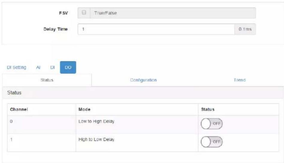
- AI Alarm Driven
After the High/Low Alarm been configured in AI channel configuration, the alarm status can be mapped in to DO channel. Choose the High Alarm or Low Alarm in Trigger Mode to active the configured DO channel.

4.2.7 Configuring the RS-485 Port of WISE-4051
WISE-4051 has one RS-485 port for Modbus gateway function, thus you can use this port to polling the data from RS-485 Modbus/RTU slave devices, like ADAM-4000, or ADAM-5000/485.
4.2.7.1 External Coils or Registers Status of RS-485 Port
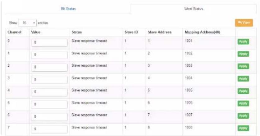
Go the "COM1" tab to check the status or configure the Modbus Master function of RS-485 port. There can be total 32 addresses of all Modbus slave to be mapped as the I/O of WISE-4051. These 32 addresses can be coils or registers. The coils will be mapped as extension bits of WISE-4051, and the registers will be mapped as extension words of WISE-4051. So in the "Status" tab, you can see the bits or words are shown in individual pages.
Column "Channel" indicate the number of bits, there are maximum 32 bits can be shown here, but you may only mapping less than 32 coils as bits, so the empty bits are invalid. Same as words may also have empty channels.
Column "Value" shows the value polling from mapped address.
Column "Status" shows the status of each bits or words, if the channel is empty which did not be mapped to Modbus slave address, the status will shows "Unavailable".
Column "Slave ID" and "Slave Address" show where the bit or word from RS-485 Modbus slave device.
Column "Mapping Address" shows the Modbus address of bits or words when WISE-4051 be polled by Modbus/TCP. The default setting of extension bits is from Modbus address 01001 of WISE-4051, and extension words is from Modbus address 41001 of WISE-4051. There are 32 address reserved for extension bits or words for WISE-4051.
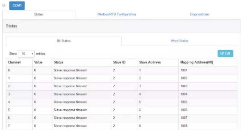
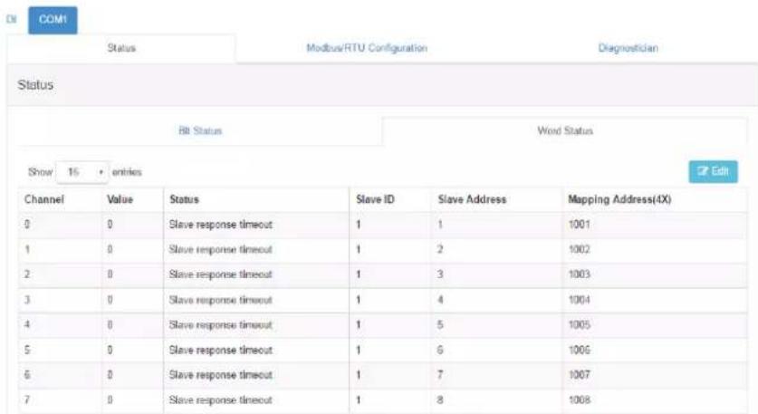
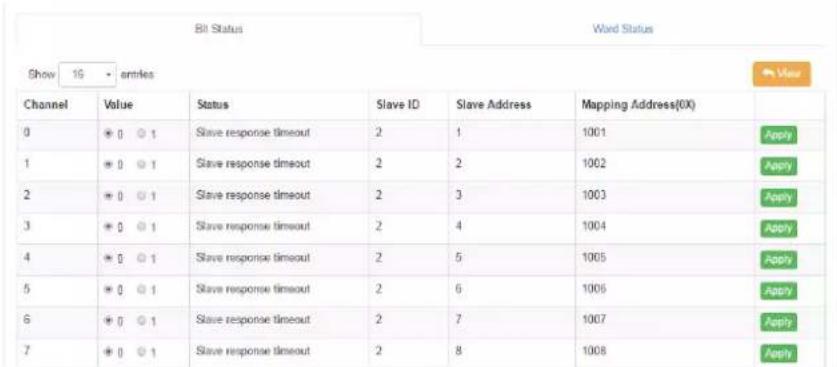
For the writable bit or word, you can click "Edit" button to switch to edit mode, change value and click "Apply" to write the Modbus address individually.
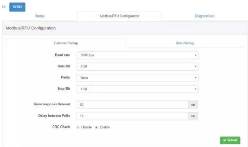
4.2.7.2 Modbus/RTU Configuration of RS-485 Port
In the "Common Setting" Tab, you can configure the parameters of WISE-4051 RS-485 port
Baud Rate: 1200, 2400, 4800, 9600, 19200, 38400, 57600, 115200 bps
Data Bit: 7, 8
■ Stop Bit: 1, 2
■ Parity: None, Odd, Even
■ Slave Respond Timeout: Here you can configure the time for waiting Modbus slave reply
■ Delay between Polls: Here you can configure the delay time between each Modbus instructions
CRC Check: Here you can enable/disable the CRC check/ignore the CRC error of Modbus
In the "Rule Setting" tab, you can configure this Modbus address of end devices you would like to polling.
Rule: There are maximum 8 rules that WISE-4051 support. Each rules can be different slave devices, in the other word, it can be maximum 8 devices connected to WISE-4051. Or you can use all rules for polling different address of same slave device.
- Slave ID: Different slave devices in same RS-485 has different slave ID, enter the slave address of Modbus devices which connected to WISE-4051 here
Type: We support 4 kinds of Modbus data type, 01 Coil Status (0x), 02 InputStatus (1x), 03 Holding Registers (4x), and 04 Input Registers (3x). After you configure one of the types in the rule, then this rule will be enabled, and WISE-4051 will start to polling after the configuration been submitted successfully.
■ Start Address: Enter the first address number that you are going to polling. The address base is 1, if you are going to polling the first address of Holding Registers, 40001, please enter number 1 here. Don't need to enter the whole address 40001.
Length: Enter the length of the address that you are going to polling in this rule. For example, if you are going to polling 40001\~40008, enter the length as 8 here. Please be noted that since WISE-4051 can polling maximum 32 address, the maximum length is 32 addresses, and the total amount of all rules should also less or equal to 32.
R/W: Here you can decide if the address in this rule will be Read or Written or not. For Coil Status and Holding Registers, you can make these addresses read only, or write only to reduce the polling effort.
■ Scan Interval (in milliseconds): Here decide the scan interval for WISE-4051 to polling Modbus slave devices. WISE-4051 will optimize the scan interval according you setting. However, the read scan interval may also depend on real case like: Baud rate, slave devices respond time, delay time between polls, etc. Go to the Diagnostician page to check the real respond time for referring the value of scan interval.
■ Mapping Channel: When the Modbus address of slave devices been configured in each rule, these addresses will also be mapped into WISE-4051. Coils of Modbus slave devices will be mapped as bits for RESTful web service and
also be mapped as coils for Modbus address of WISE-4051. Registers of Modbus slave devices will be mapped as words for RESTful web service and also be mapped as registers for Modbus address of WISE-4051. There are 32 continuous channels of bit and another 32 continuous channels of word can be mapped. Please make sure the channels for each rules are not overlapped.
Log: Here you can decide the data been polled from this rule will be logged in data logger or not.
Rule Status: The web configuration interface will check if rule settings have any overlapping or confliction. The enabled rules (enable the rule by configuring "Type") should have green icon so that the "Submit" will be shown for submitting the rules.
Note! After configuring the rules, click "Submit" to apply the rules.

Note! After changing the rule configurations, the logged data in data logger will be cleared for organizing new data structure of data logger for new configurations.
Note! Place your mouse over the table title to show the tips.

| Rule | Slave ID | Type | Start Address | Length | R/W | Scan Interval | Mapping Channel | Log | Rule Status |
| 0 | 1 | 03 Holding register | 1 | 8 | R | 1000 | 0 | # | # |
| 1 | 2 | 01 Coil status | 1 | 8 | R | 1000 | 0 | # | # |
| 2 | 2 | 01 Coil status | 17 | 8 | R | 1000 | 8 | # | # |
| 3 | 0 | Disable | 1 | 1 | R | 1000 | 0 | # | # |
| 4 | 0 | Disable | 1 | 1 | R | 1000 | 0 | # | # |
| 5 | 0 | Disable | 1 | 1 | R | 1000 | 0 | # | # |
| 6 | 0 | Disable | 1 | 1 | R | 1000 | 0 | # | # |
| 7 | 0 | Disable | 1 | 1 | R | 1000 | 0 | # | # |
In previous figure we demonstrate how to configure an ADAM-4017+ (or ADAM-4117) which slave ID is 1 and an ADAM-4055 which slave ID is 2 as the Modbus slave devices connected to WISE-4051.
ADAM-4017+ (or ADAM-4117) is an 8-ch analog input Modbus I/O modules, the Modbus address of AI0\~AI7 are 40001\~40008. In the Rule Setting page, we configure the Slave ID = 1; Type = 03 Holding Registers, since the Modbus address 40001 is start from 4; Start Address = 1 and Length = 8 for the address 40001\~40008; R/W = R, since this address is for analog input which is read only; Scan Interval = 1000ms for polling every second; Mapping Channel = 0, to mapping the data from AI0\~7 of ADAM-4017+ to channel 0\~7 of Word Status; and check the Log to log the data from ADAM-4017+.
ADAM-4055 is an 8-ch digital input and 8-ch digital output Modbus I/O modules, the Modbus address of DI0\~DI7 are 00001\~00008; the Modbus address of DO0\~DO7 are 00017\~00024. Since the address is not continuously, so we are going to configure digital input as one rule, and digital output as another rule.
For digital input channels: In the Rule Setting page, we configure the Slave ID = 2; Type = 01 Coil Status, since the Modbus address 00001 is start from 0; Start Address = 1 and Length = 8 for the address 00001\~00008; R/W = R, since this address is for digital input which is read only; Scan Interval = 1000ms for polling every second; Mapping Channel = 0, to mapping the data from DI0\~7 of ADAM-4055 to channel 0\~7 of Bit Status; and check the Log to log the data from ADAM-4055. Please be noted that the Bit Status and Word Status have individual channel number, so the Word Status for ADAM-4017+ and the Bit Status for ADAM-4055 are all start from 0.
For digital output channels: In the Rule Setting page, we configure the Slave ID = 2; Type = 01 Coil Status, since the Modbus address 00017 is start from 0; Start Address = 17 and Length = 8 for the address 00017\~00024; R/W = R/W, since this address is for digital output which can be wrote and read, you can also configured as W if you don't want to read back the value; Scan Interval = 1000ms for polling every second; Mapping Channel = 8, to mapping the data from DO0\~7 of ADAM-4055 to channel 8\~15 of Bit Status; and check the Log to log the data from ADAM-4055. Please be noted that the channel 0\~7 of Bit Status have been occupied by previous rule, so you should assign the channel number from channel 8\~31.
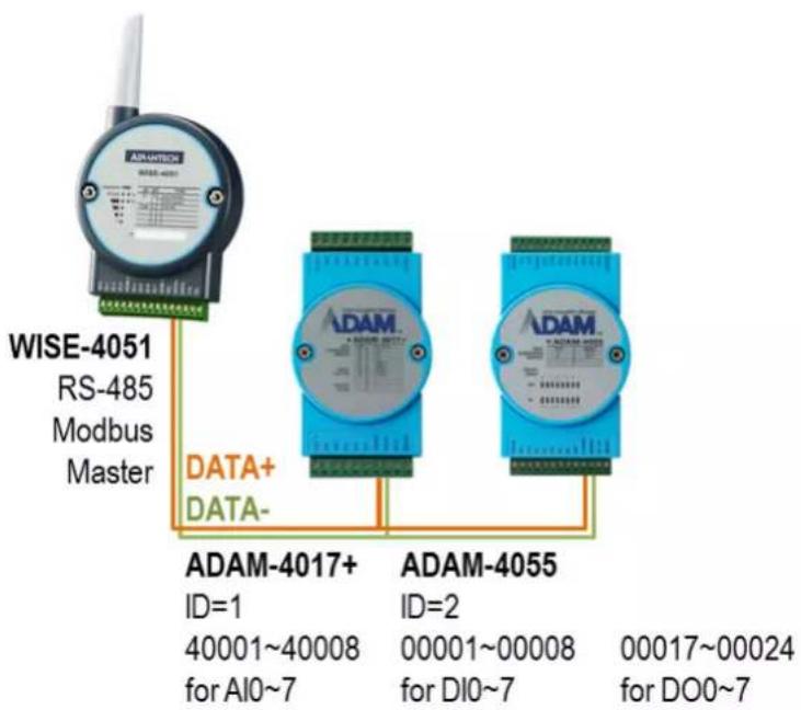
Figure 4.1 Application Scenario of WISE-4051 RS-485 Port with ADAM-4000 Modbus I/O Module
Table 4.1: Application Scenario of WISE-4051 RS-485 Port with ADAM-4000 Modbus I/O Module
| WISE-4051 ADAM | M-4055 WISE-4051 ADAM-4017+ | |||||||||
| Bit Status | Mapped Modbus Address | I/O | Slave Modbus Address | Word Status | Mapped Modbus Address | I/O | Slave Modbus Address | |||
| Ch0 010 | 01 DI0 00001 Ch0 | 410 | 01 AI0 | 40001 | ||||||
| Ch1 010 | 02 DI1 00002 Ch1 | 410 | 02 AI1 | 40002 | ||||||
| Ch2 010 | 03 DI2 00003 Ch2 | 410 | 03 AI2 | 40003 | ||||||
| Ch3 010 | 04 DI3 00004 Ch3 | 410 | 04 AI3 | 40004 | ||||||
| Ch4 010 | 05 DI4 00005 Ch4 | 410 | 05 AI4 | 40005 | ||||||
| Ch5 010 | 06 DI5 00006 Ch5 | 410 | 06 AI5 | 40006 | ||||||
| Ch6 010 | 07 DI6 00007 Ch6 | 410 | 07 AI6 | 40007 | ||||||
| Ch7 010 | 08 DI7 00008 Ch7 | 410 | 08 AI7 | 40008 | ||||||
| Ch8 010 | 09 DO0 | 00 | 017 | Ch8 410 | 09 | |||||
| Ch9 010 | 10 DO1 | 00 | 018 | Ch9 410 | 10 | |||||
| Ch10 | 01011 | DO2 | 00019 | Ch10 | 41011 | |||||
| Ch11 | 01012 | DO3 | 00020 | Ch11 | 41012 | |||||
| Ch12 | 01013 | DO4 | 00021 | Ch12 | 41013 | |||||
| Ch13 | 01014 | DO5 | 00022 | Ch13 | 41014 | |||||
| Ch14 | 01015 | DO6 | 00023 | Ch14 | 41015 | |||||
| Ch15 | 01016 | DO7 | 00024 | Ch15 | 41016 | |||||
| Ch16 | 01017 | Ch16 | 41017 | |||||||
| Ch17 | 01018 | Ch17 | 41018 | |||||||
| Ch18 | 01019 | Ch18 | 41019 | |||||||
| Ch19 | 01020 | Ch19 | 41020 | |||||||
| Ch20 | 01021 | Ch20 | 41021 | |||||||
| Ch21 | 01022 | Ch21 | 41022 | |||||||
| Ch22 | 01023 | Ch22 | 41023 | |||||||
| Ch23 | 01024 | Ch23 | 41024 | |||||||
| Ch24 | 01025 | Ch24 | 41025 | |||||||
| Ch25 | 01026 | Ch25 | 41026 | |||||||
| Ch26 | 01027 | Ch26 | 41027 | |||||||
| Ch27 | 01028 | Ch27 | 41028 | |||||||
| Ch28 | 01029 | Ch28 | 41029 | |||||||
| Ch29 | 01030 | Ch29 | 41030 | |||||||
| Ch30 | 01031 | Ch30 | 41031 | |||||||
| Ch31 | 01032 | Ch31 | 41032 | |||||||
4.2.7.3 Modbus Slave Devices Diagnostician
Since different devices will have different responds time, to have better configuration of scan interval, here WISE-4051 provides Diagnostician function for testing the respond time of each rule. You can refer to the respond timeout in this page for configuring the "Scan Interval" in "Rule Setting" page. You can reset the testing result in this page by clicking "Reset Response Time".
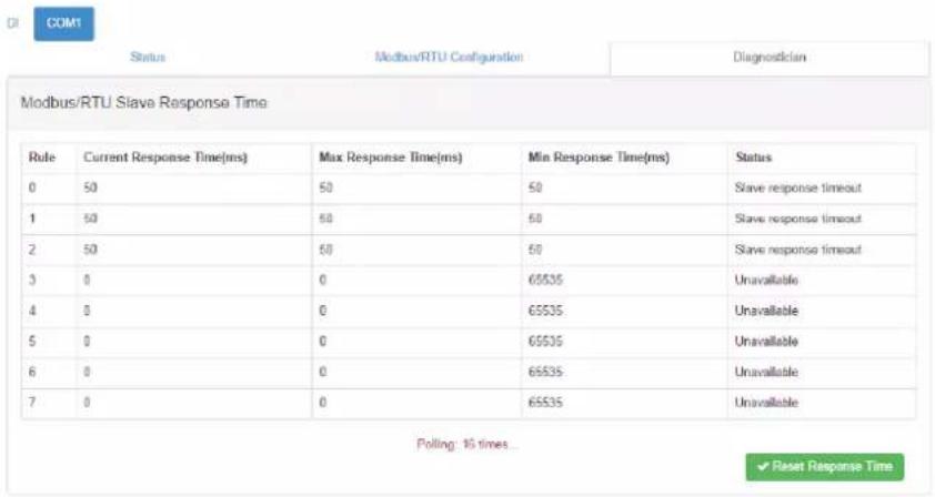
- Scan Interval of IO status
Scan Interval decides the I/O polling interval in the next part of the "I/O Status". This value will not be saved into the module, so it is only valid until the power is switched off.
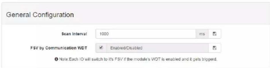
■ System Control and Maintenance
- Locate module - Helps user search for lit modules. (The status LED will be on for 30 seconds when enabled.)
- Restore to factory default -The system configuration will be cleared and restored to factory default settings when enabled.
- Reset password- Reset the password here
- Restart system -This module's system will reboot when enabled.
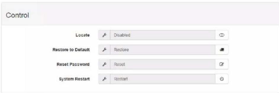
- Diagnostician
WISE modules provide a Diagnostician page for indicating the operating status of the WISE module. The status of each function is shown for easy troubleshooting.

Diagnostician
| Name | Description | Value |
| Data Logger | Event Status | Normal |
System Configuration
– Network Application
You configure the Web Server Port, Host Idle (timeout), and decide whether to enable Communication WDT here. The Web Server Port decides which Ethernet port can be used for the web service, which includes the web configuration and RESTful Web API. The default port is 80, and if you change the port number as 8080, you need to access the module through http://192.168.1.1:8080/config in AP mode for example.
The Host Idle (timeout) decides the availability of the TCP connection between the host controller and WISE. MCU-based WISE modules support four TCP connections at the same time for visiting users. It means WISE can be visited by four TCP hosts at the same time, and is not able to connect a fifth host. In this case, if one of the hosts stops communicating with the WISE module for longer than the configured host idle time, default 720 seconds, for example, the WISE module will close the TCP connection with the host.
The Communication WDT has a Host Idle time, and will be triggered when all TCP connections are closed. This includes all hosts which visit WISE and also the communication between remote servers like Dropbox or private servers. Once the WDT is enabled, it will trigger systems events like FSV of output channel or system log.
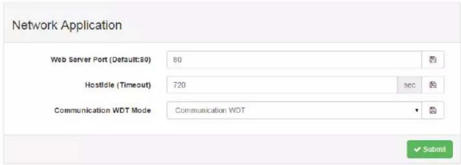
– Time & Date / SNTP
You can see the current time here, decide which time zone you use, and calibrate the time by clicking Click Me and reading the time from host devices.
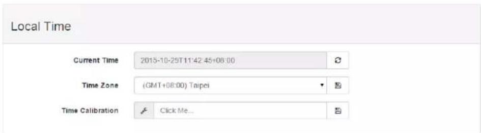
You can enable SNTP, so the module can act as an SNTP client to perform time synchronization from an assigned SNTP server.
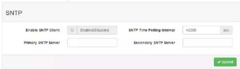
- Modbus Address
In order to provide users with more flexibility and scalability in deploying modules. It removes the limitation of the Modbus address setting and make it configurable as user's need. There are two Modbus address sections (0X and 4X) for you to configure each function item.
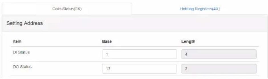
- General Configuration
The Scan Interval decides the I/O polling interval in the next part of the "I/O Status". This value will not be saved into the module, so it is only valid until the power is switched off. The FSV by Communication WDT decides whether to enable the FSV function triggered by communication with WDT. Enable the FSV function for the entire module's output channels here.
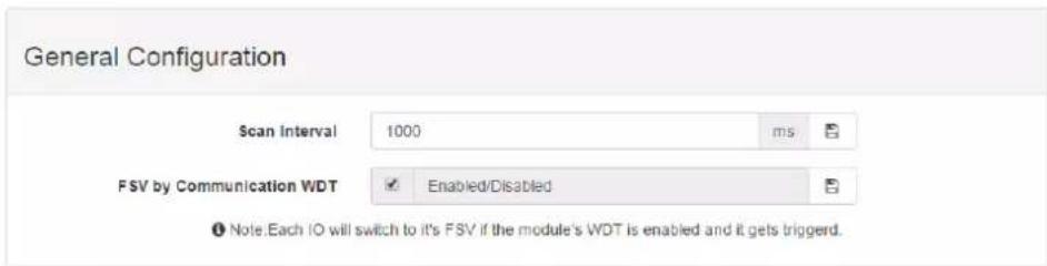
- Account Management
Change the passwords of each account here.
| Type | Password | Authority |
| Root | Change Password | Read/Write |
| Admin | Change Password | Read/Write |
| User | Change Password | Read |
■ System Configuration File
Update or Download the configuration file from WISE modules. The following items will be saved in the configuration file:
| Configuration | Information, Wireless, Network App, Time & Data, SNTP, Modbus, General Cloud, Account |
| I/O Status I/O Configuration, RS-485 (WISE-4051 only) | |
| Advanced Access | Control, Data Logger (Data log and Cloud upload) |
- Download configuration file from module
Go to the Firmware page in system configuration and click the Download configuration File button, the configurations can be saved as a file.
- Update configuration file to module
Go to the Firmware page in system configuration and click the icon to select which configuration file is going to be uploaded from the computer. Before uploading the configuration file to the module, select whether or not to apply the IP settings to the WISE module.
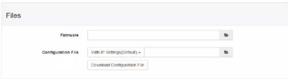
■ Firmware Version
- Check Version
The firmware version is shown in the "System Information" page. At the end of the configuration web page, check the version of configuration web page. For normal release module, the version of configuration web page will increase with the firmware version, as these have to be updated at the same time.
| Module Name | Module Description | Firmware Description |
| WISE-4012 | 2-channels digital output, 4-channels universal input | Fw:A0.91 B00, Boolloader:A0.90 B00 |

- Update Firmware
Go to the Firmware page in system configuration and click the icon to select which firmware file you are going to update. You can find the latest official release firmware file at the Advantech support site (http://support.advantech.com/support/).
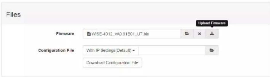
■ Access Control for Security
To avoid unauthorized access, manage which host PC or device can remotely control the WISE-4000 module by IP or MAC Address. Enable one of the rows and enter the IP address or MAC address which allows access to WISE-4000 devices.
Note! For WISE-4000 wireless modules, users can only configure access control by the IP address, not the MAC address.

Access Control
| Enable/Disable | IP(Ex: 255.255.255.255) |
| 0 | 255.255.255.255 |
| 1 | 255.255.255.255 |
| 2 | 255.255.255.255 |
| 3 | 255.255.255.255 |
Data Logger
The WISE-4000 series supports data log functions, the I/O status can be logged in the module and also be queried from the module.
- Time & Date / SNTP
Before you start the log function, confirm the RTC time inside the WISE module is configured to the correct time. Standard WISE modules, not including the WISE-4012E, come with an RTC battery. Once the RTC time has been configured, you don't need to synchronize the time with SNTP server. The time will be kept in the RTC with the battery. For the WISE-4012E, which doesn't have an RTC battery, you need to synchronize the time with the SNTP server.
– Data Configuration
I/O Data
You can configure the Log Conditions to be logged by time period or by communication with WDT. If you check the By Period box, it enables periodic logging, and the log period can be decided in following box. Note that the period is increased by 0.1 seconds, meaning that if the user configures "600" here, the status of the I/O will be logged each minute. If you check the box By Communication WDT, it will been enabled, once the condition of the WDT has been met, the status of the I/O will be logged.
For the analog input channel, data can be logged by the AI Deviation Rate (Dividing difference between present sample value and previous sample value by the total range value). Here you can enter the percentage of deviation rate to be the criteria for triggering logger.
All the data can be kept even if the module is powered off, however, you can clear all data in the logger when powering up WISE module. Just check the Clear Log when Power Up box. When the data is logged to maximum memory capacity, logger will stop logging by default. You can check the box of the Circular Log when Memory Full to overwrite the earliest data.
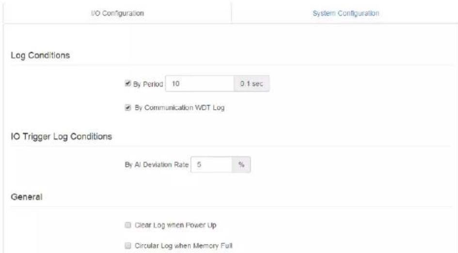
The Channel Fields tab is to decide which I/O channel's status will be logged, and if the change of the status also need to be logged or not. Note that the log memory will be cleared once any parameter is changed in the Channel Fields, and also in IO Fields.
For a digital channel, check the Log Enabled box to log the status of checked channel periodically. Or check the Change of State to trigger data logged by status change. For the universal input channel, the DI channel should be configured in AI/UI page.
Log Data
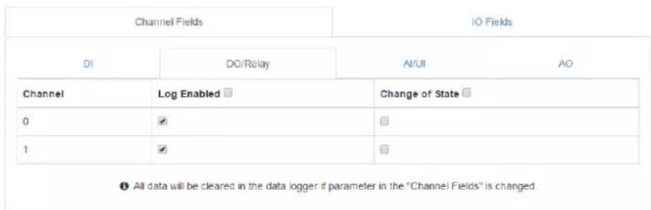
For AI channels, check the AI Log Enabled box to log the status of checked channel periodically. Or check AI Deviation Enabled to trigger data logged when the AI value changed over the deviation rate which been configured in the page above.
Log Data
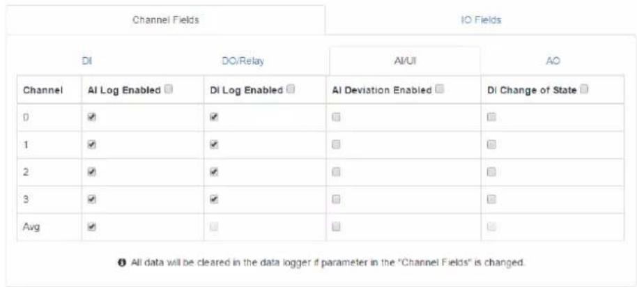
The IO Fields tab is to decide which AI data will be logged. Note that the log memory will be cleared once any parameter changed in the Channel Fields and IO Fields tabs.
Log Data
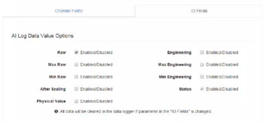
System Data
The WISE data logger function not only logs the I/O status, but also logs system events for module diagnostics or troubleshooting. You can decide what kind of system events you would like to log here.
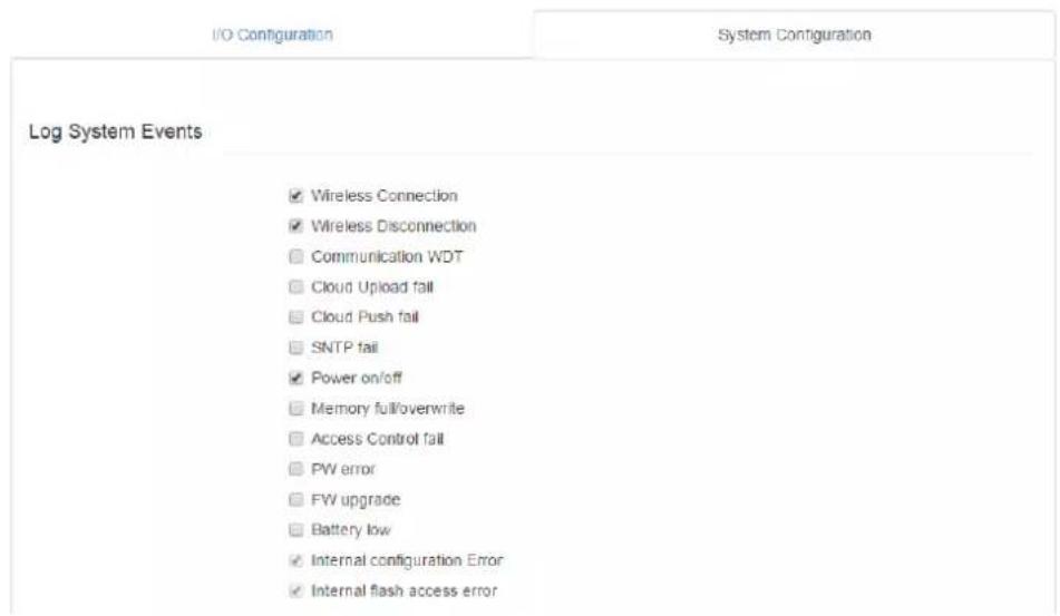
- Logger Configuration
In the previous page, you configured which data is logged. In this page you can enable the local memory storage function. There are separate switches for enabling logging I/O data or system data. You can turn ON the switches to enable logging.
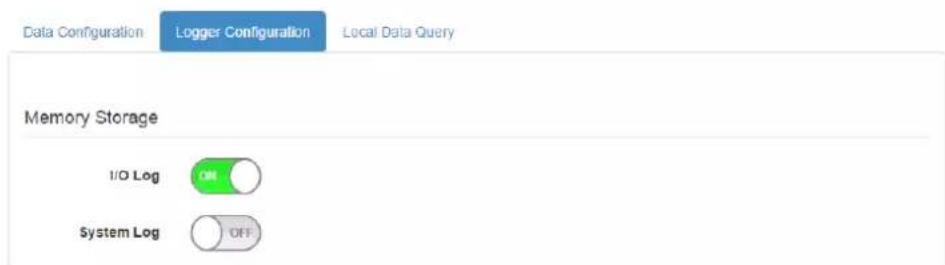
- Local Data Query
The logged data can be queried from the WISE module. Due to the limitation of MCU-based WISE modules, the file will be saved in a *.json file. You can visit https://json-csv.com/ to convert the data from *.json to *.csv.
Before querying the logged data, you can configure the format of the file. You can decide whether the data comes with a UUID or MAC ID, and decide the type of time stamp. For the latest version WISE module version, which supports Local Date and Time (GMT) the time stamp will look like: "2015-08-27T15:20:29+08:00", or if it supports Coordinated Universal Time (UTC) that the time stamp will looks like: "1440660089".
After deciding the data format you can query the data by the Amount of Latest Data for a quantity of data, or by Time Filter for a period of data. However, if the amount of data is not too large, you can also choose No Filter Enabled to query all the data.
Now you can click Query to query the data from local memory. Then the data will be shown in a chart and table. Click Save to download the data from the WISE module in a *.json file. Or you can click Clear to clear all the data in local memory.
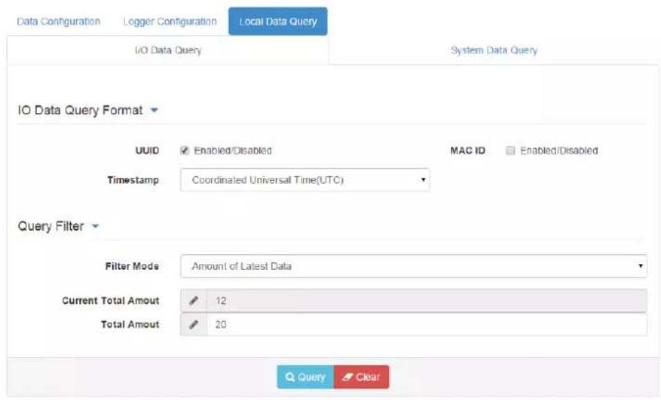
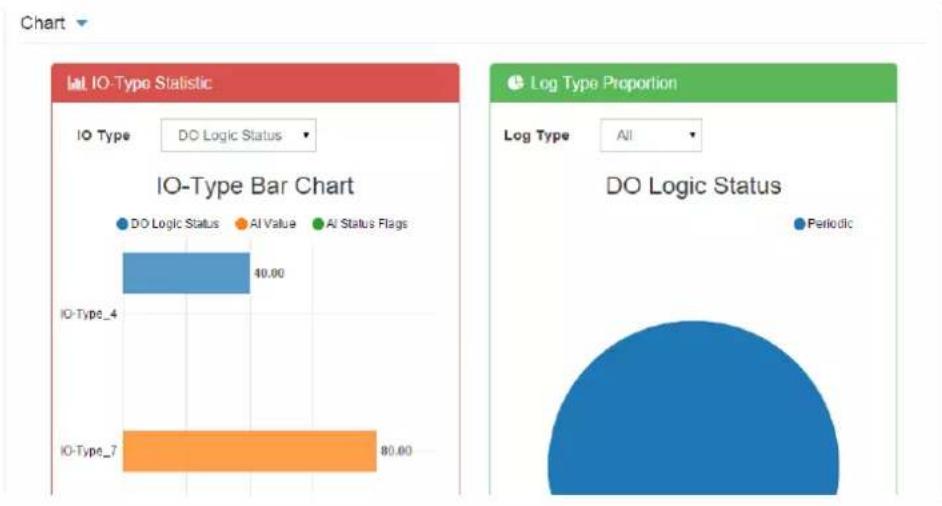
bar
| IO-Type | Category | Value | |---------|--------------------|--------| | IO-Type_4 | DO Logic Status | 40.00 | | IO-Type_7 | AI Value | 80.00 || Log Type | Timestamp | UUID | Slot | Channel | I/O-type | Value |
| 128 | 1446090622 | WISE-4012_00D0C9CC0099 | 0 | 0 | 4 | 0 |
| 128 | 1446090622 | WISE-4012_00D0C9CC0099 | 0 | 1 | 4 | 0 |
| 128 | 1446090622 | WISE-4012_00D0C9CC0099 | 0 | 0 | 7 | 32767 |

■ Cloud Logger (WISE-4000 wireless series only)
- Dropbox
Refer to section 4.2.8 Configuring Cloud Server for Dropbox cloud logger.
- Private Server
If you don't want to push the data to public file-based cloud like Dropbox, WISE also supports the Private Server function which pushes data to a private web server setup by yourself. You can setup your own web service to receive the data from WISE module, or use the example agent on your own server to receive the files pushed from the WISE module.
Go to the Cloud Configuration page and select the service as Private Server. Then configure the Private Server Setting. If you would like to use the example agent provided by WISE, you need to confirm the Server IP and Server Port, and make sure the server port you've configured had not been occupied by another application on your private server. To setup your own application to receive the file from WISE, you may need to configure the URL. SSL security also supports Dropbox to provide you with a safe private cloud solution. Once SSL security had been enabled, you need to setup the SSL service on your private server.
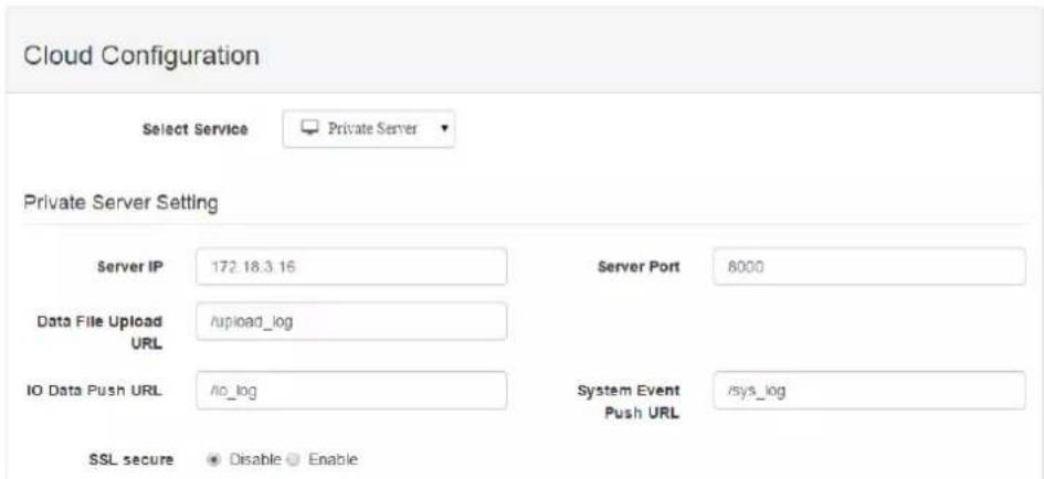
If you are not able to setup the SSL service, there is another option for safety. You can have Authentication for the private server with a User Name and Password which is also provided by our example agent.

After Cloud Configuration had been configured as a private server, you can go back to the Logger Configuration page in Data Logger. Before switching Cloud Upload to ON, you can configure the data upload criteria, and for I/O signal or system diagnosis individually. The criteria can be Item Periodic Interval mode for pushing data by a quantity of data, or Time Periodic Interval mode for pushing data by a period of time (Unit: 0.1 sec). If you don't want to upload the I/O or system data, choose Disable. After the upload criteria have been configured, you can switch Cloud Upload ON and start uploading. Then the data will be pushed to the cloud in *.csv file.
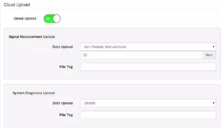
- Push Notification
For Cloud Logger functions Private Server, the data all comes from the local memory of WISE, so you can see it from the WISE data logger and make a batch of data as a file, then push it to the web server. Then push the latest data when the log condition has been triggered, like the changes of DI status. The WISE module will push a notification in JSON format to the private server as configured above, and then you have the latest WISE module data. You can switch the I/O Log or System Log ON, then the WISE module will start pushing the latest logged data to the private server.

4.2.8 Configuring Cloud Server (WISE-4000 wireless series only)
- Make sure the WISE-4000 module is able to access the Internet, and the device that's going to configure the WISE-4000 module is within the same IP domain as the WISE-4000 module
- Go to the Cloud tab of Configuration.
Note! The following instructions use Dropbox. Make sure Dropbox provide their service in your region or find an alternative public cloud service.

- Select Dropbox as the cloud server.
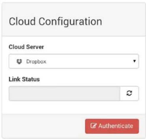
- The browser will open a new window for Dropbox. Enter your Dropbox account information including E-mail and Password, then click "Sign in".
![Dropbox - API Request Authorization - Sign in - Google Chrome Dropbox, Inc [US] https://www.dropbox.com/1/oauth2/authorize?cli Sign in to Dropbox to link with WISE Cloud Logger Email Password Forgot your password? Sign in](/content/2026/05/895695/images/5cd68bde28c28d2dec6d25ebe55a9b7aa534554b99c51ec1612a3799bce460e1.jpg)
- After logging in, click "Allow" to allow WISE Cloud Logger Apps to access your Dropbox account to store the data log file.
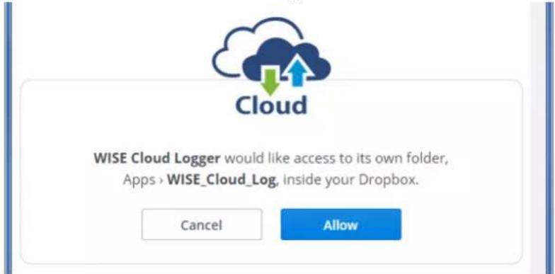
- Dropbox will then provide a code, copy this code and return to the configuration web page of the WISE module.
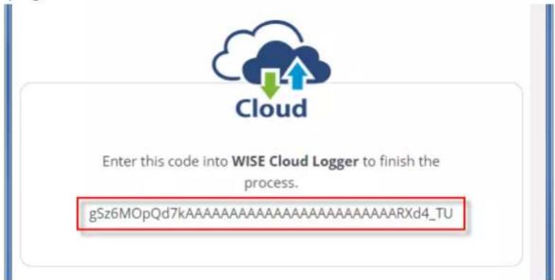
- Click "Next" to enter the code.
Grant Cloud Access
Step 1
Login to your Cloud Website and grant access of "WISE Cloud".
Next

- Paste the code provided by WISE Cloud Logger, then click "Submit".
Grant Cloud Access
Step 2
Copy the "User Code" on Cloud Service Website and paste to the following column:

gSz6MOpQd7kAAAAAAAAAAAAAAAAARXd4_TU
√ Submit

- If your WISE-4000 module is correctly connected to the Internet, you will be able to set the functions successfully. Click "Close" to return to Configuration.
Grant Cloud Access
X
Setting Successfully
* Close

- You will then be able to see the "Link Status" shows "Ready".

Configuration
Information
Wireless
Network App
Time & Date
SNTP
Modbus
Control
General
Cloud
Firmware
Account
Cloud Configuration
Cloud Service

Dropbox

Link Status
Ready


Configure
4.3 Configure WISE-4000 with ADAM.NET Utility
ADAM.NET Utility, which is designed with graphical operation interface, is aimed to offer users directly configure, control WISE-4000 module, and monitor the real-time status of remote WISE-4000 module via Ethernet or Wireless connection.
To keep you informed with latest update, you also can check it from the following download link on Advantech website.
http://support.advantech.com.tw/Support/DownloadSRDetail.aspx?SR_ID=1-2AKUDB
Note!

Before installing ADAM.NET Utility, you need to install .NET
Framework 2.0 or higher version.
System requirement
- Microsoft Windows XP/7
- At least 32 MB RAM
- 20 MB of hard disk space available
– VGA color or higher resolution monitor - Mouse or other pointing devices
-
10/100 Mbps or higher Ethernet Card
-
Install ADAM.NET Utility in your computer.
(After successfully installation, there will be a shortcut generated on the screen)

- Double click the shortcut icon, and then you will see the main operation window.
- Click Search Module icon in Toolbar. You will see all online modules in the left Module Tree screen and an unconfigured new module, whose default password is 00000000, will appear on the Others section as below. Now you can define the network mode of the module in the beginning. After that, you will be able to perform other settings.
Note! The default password is 00000000

4.3.1 Operation Framework
The operation window mainly contains 4 areas, including Menu, Toolbar, Module Tree screen and Main Operation screen.
4.3.1.1 Menu
a. File
Open Favorite Group
You can import the favorite configuration group file (.XML) from your computer.
■ Save Favorite Group
You can save the favorite group configuration group as XML file to your computer.
■ Auto-Initial Group
If you want to have the same favorite group configuration when you exit ADAM.NET utility and launch it again, you need to check this option.
Exit
Exit ADAM.NET Utility.
b. Tools
Search Device
Search all the WISE-4000 modules you connected in local Ethernet.
■ Add Devices to Group
It's used to add WISE-4000 modules to your favorite group. After activating search function, all online modules will show on Module Tree Screen area. Now you can enable this function to select the device you want to add in the Module Tree Screen.
Group Configuration
Group Configuration is on WISE-4000 series module. It can help you efficiently configure or maintain massive WISE-4000 modules with the same configuration file or firmware upgrade at one time in the local network. The following steps will instruct you how to operate it.
■ Terminal for Command Testing
WISE-4000 series module Modbus/TCP as communication protocol, so you can launch the terminal to directly communicate with WISE-4000 series module by these two protocols.
Print Screen
You can save current ADAM.NET Utility screen into an image file by this option.
HTML File Packager
You can pack your user web page by this tool:
-
Put all the files that going to pack in same folder, and "Browse..." the folder
-
Press "Save as..." and give a file name after package
-
Check all the files had been selected in "File List"
-
Check "Gzip Compression" to reduce the file size
-
After press the "Apply" button, your user web page will be compressed as "*.ehf" file, then you can download the file into your WISE module
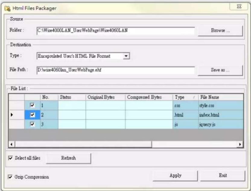
c. Setup
- Favorite Group
You can configure your favorite group including add one new device, modify or delete one current device, sort current devices and diagnose connection to one device.
■ Refresh Serial and Ethernet
ADAM.NET utility will refresh the serial and LAN network connection situation.
Add COM Ports
This option is used to add serial COM ports in ADAM.NET Utility. You won't need to use this option for WISE-4000 modules.
Show TreeView
Check this option to display the Module Tree Screen area.
Allow Calibration
Check this option to allow calibration function enabled on AI/O module.
d. Help
■ Check Up-to-Date on the Web
It will automatically connect to support and download page of Advantech website when it enabled. You can find and download the latest version of WISE-4000 utility there.
■ About ADAM.NET Utility
The current version of ADAM.NET Utility is installed on your computer.
4.3.1.2 Toolbar
There are 8 graphical icons for common used options of Menu on the toolbar.

Definition (from left to right)
- Open favorite group
- Save favorite group
- Search Modules
- Add Devices to Group
- Terminal for Command Testing
- Group Configuration
- Monitor Data Stream/Event
- Print Screen
4.3.1.3 Module Tree Screen
The Module Tree Screen locates on the left part of ADAM.NET utility operation window. There are four categories in this area:
Serial
All serial I/O Modules (ADAM-4000 and ADAM-5000 RS-485 serial modules) connected to the host PC will be listed in this category.
Ethernet
All Ethernet I/O Modules (WISE-4000, ADAM-6000, ADAM-6100, and ADAM-5000 TCP modules) connected to the host PC will be listed in this category.
Favorite Group
You can define which devices listed in the three categories above into your personal favorite group. This will make you easier to find your interested modules. Right click on the WISE-4000 device item under the Favorite Group item and you can select Add New Group to create a new group. After you create your own group, right click on your group and Add New Device into your group. You can also select Diagnose connection to check the communication.
ADAM-4500\_5510 Series
This is a DOS interface utility for remote controllers such as ADAM-4500 and ADAM-5510 series.
Wireless Sensor Networks
All wireless I/O Modules (ADAM-2000 modules) connected to the host PC, through wireless gateway, will be listed in this category.
4.3.1.4 Main Operation Screen
Main Operation Screen located on the right side of utility includes I/O status display and function setting. You can select different items in Module Tree Screen, and then Main Operation Screen will change dependently. You can do all configurations and test in this area.
In Information page (after clicking Ethernet), you can configure Connection/Send/Receive/Scan Timeout. The supervisor password is a shortcut to let you enter a password at one time which's applied for certain modules, so you don't need to enter the same password for each module when you check it.
4.3.2 Configure WISE-4000
- Configure the computer's IP address as the same domain as WISE-4000 module. For the new WISE-4000/LAN Series which default IP address is 10.0.0.1, the IP address of computer can be configured as 10.0.0.99 for example as following.
- Open the Adam/Apax .NET Utility then you can see the IP address of computer been shown under "Ethernet" tree. You can right click to refresh the subnodes of this tree. Or click "Search Device" to find WISE-4000 module.
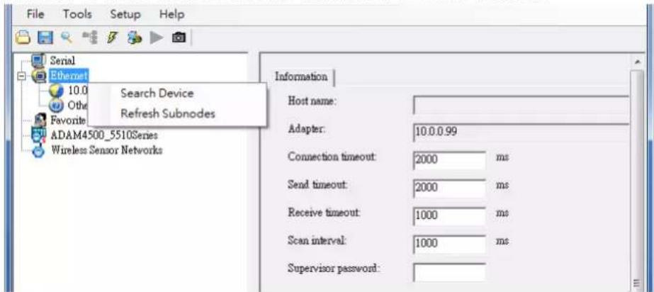
- Users can also right click the IP address to find WISE-4000 module.
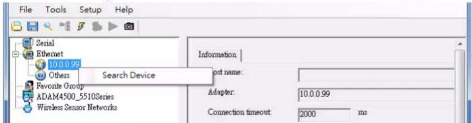
- After the module been found, it will be listed under IP address in same domain, you can login the embedded web configuration web page for further configuration as introduced in previous section
![Serial Ethernet 10.0.0.99 10.0.0.1-[WISE-4010/LAN] Others Favorite Group ADAM4500_5510Series Wireless Sensor Networks Login Info Device Info QR WISE-4010/LAN Web Account: root Password: Login](/content/2026/05/895695/images/a48f2124169b7326df25d2d4e7fb9423c577115578e00c2085db7aebc3f7abcb.jpg)
- There are some function provide in same pages in utility, first you can enter the account and password faster in "Login Info" tab.
![Serial Ethernet 10.0.0.99 10.0.0.1-[WISE-4010/LAN] Others Favorite Group ADAM4500_5510Series Wireless Sensor Networks Login Info Device Info root admin user Password Password: Login GE-4010/LAN Web](/content/2026/05/895695/images/33ad2b5d3295d588c486d1ce5ab1c21e7f621812975e5e142af0ad365f5a3240.jpg)
- In the "Device Info" tab, the detail information of this module will be shown
![Serial Ethernet 10.0.0.99 10.0.0.1-[WISE-4010/LAN] Others Favorite Group ADAM4500_5510Series Wireless Sensor Networks Login Info Device Info Device Name : WISE-4010/LAN Device Description : Firmware Version : A0.97 B00 MAC Address : 00-D0-C9-66-00-A4 IP Address : 10.0.0.1 Subnet Address : 255.255.0.0 Default Gateway : 0.0.0.0 http://10.0.0.1:80/config](/content/2026/05/895695/images/b792c6f3f5545d878b5dc4d687267ad034936f4e54d1a3ca7cd4fcbe50b635f5.jpg)
- The "QR" tab will generate the QR code of the web configuration web page for mobile device to access the module. User can also click the QR code to open the browser for further configuration.
![Serial Ethernet 10.0.0.99 10.0.0.1-[WISE-4010/LAN] Others Favorite Group ADAM4500_5510Se Wireless Sensor Net Login Info Device Info QR WISE-4010/LAN Web When scanning QR code, you will automatically be taken to the module website URL. Close](/content/2026/05/895695/images/46f0be5fe770ed22994e52707064ec0590aa29244afc9eb6462a5a78b399f559.jpg)
Note!If you are not able to search the module, you can configure the SW1 behind the module to initial mode. After power up and search the module in utility, user can find the module with default IP address, and the device name will be shown in "Others" tree with (*) sign. So user can change the device network setting in this page. Or try to locate the device and also reset the password with same page. After the new network setting been apply, please configure the SW1 back to normal mode and power up again to reboot in new network setting.
 Favorite Group ADAM4500_5510Series Wireless Sensor Networks Setting | Network setting: MAC address : 00-D0-C9-66-00-A4 IP address : 10.0.0.1 Subnet Address : 255 255 0.0 Default gateway : 0.0.0.0 Ethernet Mode Configured Static DHCP Port Number Setting (0~65535) 80 Apply change Others: Locate Enable Reset Password](/content/2026/05/895695/images/4b0c15717a067fb7834729fd69813e36a7e8f63db6681053f9d7e7c43c135068.jpg)
4.4 Site Survey Tool for WISE-4000 Wireless Series
WISE-4000 Wireless Series provides Site Survey Tool for testing the communication quality between WISE-4000 wireless module with wireless access point or wireless router.
4.4.1 Site Survey Architecture
Wiring the wireless AP with the PC installed with Site Survey Tool (Utility), if possible, the network should only have PC, AP, and WISE-4000 only.
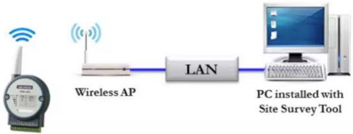
flowchart
graph LR
    A["Wireless AP"] --> B["LAN"]
    B --> C["PC installed with Site Survey Tool"]
4.4.2 Site Survey Mode
WISE module will go to site survey mode operation for testing communication quality. Most of the functions of WISE module will temporally stop to doing site survey operation. And the LED status will work as following:
| LED Color Indication Behavior | |
| Status Green OFF Site Survey mode | |
| Com Yellow Blink Site Survey data packet TX/RX | |
| AP/Infra | Green OFF Site Survey mode (Station Mode) |
| Signal Strength | Green Blink Site Survey mode |
4.4.3 Site Survey Tool
Search WISE-4000 module as described in the last section, after click the module shown in Ethernet tree. There is a "Site Survey" icon as following. Click the "Site Survey" icon to open site survey tool windows as following. Click "Start" to set the module in site survey mode and start the site survey tool. User can click "Restart" to restart the testing result, or click "Stop" to stop the testing and set the module back to normal operation.
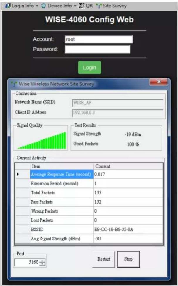
Connection
Network Name (SSID): Show which wireless AP is connected.
Client IP Address: Show the IP address of the wireless adapter of PC
Signal Quality
Show the signal strength by bar chart
Testing Results
Signal Strength: The average result of the signal strength during testing
Good Package: The percentage of passed packets during testing
Current Activity
Detail information of each testing packets
Port
User can configure which UDP port of PC is assigned for site survey testing
Appendix A
I/O Modbus Mapping Table
A.1 Modbus Function Code Introduction
To full-fill the programming requirement, there is a series of function code standard for user's reference.
| Code (Hex) Name Usage | ||
| 01 Read Coil Status Read Discrete Output Bit | ||
| 02 Read Input Status Read Discrete Input Bit | ||
| 03 Read Holding Registers | Read 16-bit register. Used to read integer or floating point process data. | |
| 04 Read Input Registers | ||
| 05 Force Single Coil Write data to force coil ON/OFF | ||
| 06 Preset Single Register Write data in 16-bit integer format | ||
| 08 Loopback Diagnosis Diagnostic testing of the communication port | ||
| 0F Force Multiple Coils Write multiple data to force coil ON/OFF | ||
| 10 | Preset Multiple Registers | Write multiple data in 16-bit integer format |
A.2 WISE-4010/LAN Modbus Mapping Table
Address (0X):
| Address (0X) | Channel | Description | Attribute |
| 00017 0 | DO ValueRead/Write | Read/Write | |
| 00018 1 | |||
| 00019 2 | |||
| 00020 3 | |||
| 00101 0 | Reset Historical Min. AI Value | Write | |
| 00102 1 | |||
| 00103 2 | |||
| 00104 3 | |||
| 00105 Average Ch 0~3 | |||
| 00111 | 0 | Reset Historical Min. AI Value | Write |
| 00112 | 1 | Write | |
| 00113 | 2 | Write | |
| 00114 | 3 | Write | |
| 00115 | Average Ch 0~3 | Write | |
| 00121 0 | Open-Circuit Flag Read(Burnout) | Read | |
| 00122 1 | |||
| 00123 2 | |||
| 00124 3 | |||
| 00131 0 | High Alarm Flag | Read | |
| 00132 1 Read | |||
| 00133 2 Read | |||
| 00134 3 Read | |||
| 00135 Average Ch 0~3 Read | |||
| 00141 0 | Low Alarm Flag | Read | |
| 00142 1 Read | |||
| 00143 2 Read | |||
| 00144 3 Read | |||
| 00145 Average Ch 0~3 Read | |||
Address (4X):
| Address (4X) Channel Description Attribute |
| 40211 Module Name 1 Read |
| 40212 Module Name 2 Read |
| 40221 All AI AI Channel Enabled Read/Write |
| 40303 All DO | DO Value | Read/Write | |
| 40001 0 | Read | ||
| 40002 1 | Read | ||
| 40003 2 | AI Value Read | ||
| 40004 3 | Read | ||
| 40005 Average Ch 0~3 | Read |
| 40009-40010 | 0 | Read/Write | |
| 40011~40012 | 1 Read/Write | Pulse Output | |
| 40013~40014 2 Read/Write | Low Level Width | ||
| 40015~40016 3 Read/Write | |||
| 40017-40018 | 0 | Read/Write | |
| 40019~40020 1 | Pulse Output | Read/Write | |
| 40021~40022 2 | High Level Width | Read/Write | |
| 40023~40024 3 | Read/Write |
| 40025-40026 | 0 | Read/Write |
| 40027~40028 1 | Pulse Output Number Read/Write(0 for continuous output)Read/Write | |
| 40029~40030 2 | ||
| 40031~40032 3 | Read/Write | |
| 40033~40034 0 | Set Incremental Pulse Output Number | Read/Write |
| 40035~40035 1 Read/Write | ||
| 40037~40038 2 Read/Write | ||
| 40037~40040 3 Read/Write | ||
| 40101~40102 0 | AI Status* | Read |
| 40103~40104 1 Read | ||
| 40105~40106 2 Read | ||
| 40107~40108 3 Read | ||
| 40111 0 | Historical Maximum AI Value | Read |
| 40112 1 Read | ||
| 40113 2 Read | ||
| 40114 3 Read | ||
| 40115 Average Ch 0~3 Read | ||
| 40121 0 | Historical Minimum AI Value | Read |
| 40122 1 Read | ||
| 40123 2 Read | ||
| 40124 3 Read | ||
| 40125 Average Ch 0~3 Read | ||
| 40131~40132 0 | AI Floating Value (IEEE754) | Read |
| 40133~40134 1 Read | ||
| 40135~40136 2 Read | ||
| 40137~40138 3 Read | ||
| 40139~40140 Average Ch 0~3 Read | ||
| 40151~40152 0 | Historical Maximum AI Floating Value (IEEE754) | Read |
| 40153~40154 1 Read | ||
| 40155~40156 2 Read | ||
| 40157~40158 3 Read | ||
| 40159~40160 Average Ch 0~3 Read | ||
| 40171~40172 0 | Historical Minimum AI Floating Value (IEEE754) | Read |
| 40173~40174 1 Read | ||
| 40175~40176 2 Read | ||
| 40177~40178 3 Read | ||
| 40179~40180 Average Ch 0~3 Read | ||
| 40191 0 | AI Value After Scaling | Read |
| 40192 1 Read | ||
| 40193 2 Read | ||
| 40194 3 Read | ||
| 40195 Average Ch 0~3 Read | ||
| 40201 0 | AI Type Code** | Read/Write |
| 40202 1 Read/Write | ||
| 40203 2 Read/Write | ||
| 40204 3 Read/Write | (The type codes of channels for average value can't be changed.) | |
| 40205 Average Ch 0~3 Read | ||
* AI Status (2 Registers)
| Lower Register Higher Register | |||
| Bit Description Bit Description | |||
| 0 Fail to Provide AI Value 0 DI triggered to Safety Value | |||
| 1 Over Range 1 DI triggered to Startup Value | |||
| 2 Under Range 2 Reserved | |||
| 3 Open Circuit / Burnout 3 Reserved | |||
| 4 Reserved | 4 Reserved | ||
| 5 Reserved | 5 Reserved | ||
| 6 Reserved | 6 Reserved | ||
| 7 ADC Initializing/Error | 7 Reserved | ||
| 8 Reserved | 8 Reserved | ||
| 9 Zero/Span Calibration Error | 9 Reserved | ||
| 10 Reserved | 10 | Reserved | |
| 11 Reserved | 11 | Reserved | |
| 12 Reserved | 12 | Reserved | |
| 13 Reserved | 13 | Reserved | |
| 14 Reserved | 14 | Reserved | |
| 15 Reserved | 15 | Reserved | |
** AI Type Code (2 Registers)
| Type Code | Input Range |
| 0x1080 | 4~20 mA |
| 0x1082 | 0~20 mA |
A.3 WISE-4050/LAN Modbus Mapping Table
| Address 0X Channel Description Attribute | ||
| 00001 0 | DI Value | Read |
| 00002 1 Read | ||
| 00003 2 Read | ||
| 00004 3 Read | ||
| 00017 0 | DO Value | Read/Write |
| 00018 1 Read/Write | ||
| 00019 2 Read/Write | ||
| 00020 3 Read/Write | ||
| 00033 0 | Counter Status(0: stop1: start) | Read/Write |
| 00034 1 Read/Write | ||
| 00035 2 Read/Write | ||
| 00036 3 Read/Write | ||
| 00037 0 | Clear Counter(1: write to clear value) | Write |
| 00038 1 Write | ||
| 00039 2 Write | ||
| 00040 3 Write | ||
| 00041 0 | Clear Overflow(1: counter overflow,auto set to 0 after read) | Read/Write |
| 00042 1 Read/Write | ||
| 00043 2 Read/Write | ||
| 00044 3 Read/Write | ||
| 00045 0 | DI Latch Status(1: DI latched,0: write to clear latch) | Read/Write |
| 00046 1 Read/Write | ||
| 00047 2 Read/Write | ||
| 00048 3 Read/Write | ||
| Address 4X Channel Description Attribute | |||
| 40211 - Module Name 1 Read | |||
| 40212 - Module Name 2 Read | |||
| 40301 All DI DI Value Read | |||
| 40303 All DO DO Value | Read/Write | ||
| 40001~40002 | 0 | Read | |
| 40003~40004 | 1 Read | Counter/Frequency Value | |
| 40005~40006 | 2 Read | ||
| 40007~40008 | 3 Read | ||
| 40009~40010 0 | Read/Write | ||
| 40011~40012 1 Read/Write | Pulse OutputLow Level Width | ||
| 40013~40014 2 Read/Write | |||
| 40015~40016 3 Read/Write | |||
| 40017~40018 0 | Read/Write | ||
| 40019~40020 1 Read/Write | Pulse OutputHigh Level Width | ||
| 40021~40022 2 Read/Write | |||
| 40023~40024 3 Read/Write | |||
| 40025~40026 0 | Read/Write | ||
| 40027~40028 1 Read/Write | Set AbsolutePulse Output Number(0 for continuous output) | ||
| 40029~40030 2 Read/Write | |||
| 40031~40032 3 Read/Write | |||
| 40033~40034 0 | Read/Write | ||
| 40035~40036 1 Read/Write | Set IncrementalPulse Output Number | ||
| 40037~40038 2 Read/Write | |||
| 40039~40040 3 Read/Write | |||
| Address 0X Channel Description Attribute | ||
| 00001 0 | DI Value | Read |
| 00002 1 Read | ||
| 00003 2 Read | ||
| 00004 3 Read | ||
| 00017 0 | DO Value | Read/Write |
| 00018 1 Read/Write | ||
| 00019 2 Read/Write | ||
| 00020 3 Read/Write | ||
| 00033 0 | Counter Status(0: stop1: start) | Read/Write |
| 00034 1 Read/Write | ||
| 00035 2 Read/Write | ||
| 00036 3 Read/Write | ||
| 00037 0 | Clear Counter(1: write to clear value) | Write |
| 00038 1 Write | ||
| 00039 2 Write | ||
| 00040 3 Write | ||
| 00041 0 | Clear Overflow(1: counter overflow,auto set to 0 after read) | Read/Write |
| 00042 1 Read/Write | ||
| 00043 2 Read/Write | ||
| 00044 3 Read/Write | ||
| 00045 0 | DI Latch Status(1: DI latched,0: write to clear latch) | Read/Write |
| 00046 1 Read/Write | ||
| 00047 2 Read/Write | ||
| 00048 3 Read/Write | ||
| Address 4X Channel Description Attribute | |||
| 40211 - Module Name 1 Read | |||
| 40212 - Module Name 2 Read | |||
| 40301 All DI DI Value | Read | ||
| 40303 All DO | DO Value | Read/Write | |
| 40001~40002 | 0 | Counter/Frequency Value | Read |
| 40003~40004 | 1 Read | ||
| 40005~40006 | 2 Read | ||
| 40007~40008 | 3 Read | ||
| 40009~40010 0 | Read/Write | ||
| 40011~40012 1 Read/Write | Pulse OutputLow Level Width | ||
| 40013~40014 2 Read/Write | |||
| 40015~40016 3 Read/Write | |||
| 40017~40018 0 | Read/Write | ||
| 40019~40020 1 Read/Write | Pulse OutputHigh Level Width | ||
| 40021~40022 2 Read/Write | |||
| 40023~40024 3 Read/Write | |||
| 40025~40026 0 | Read/Write | ||
| 40027~40028 1 Read/Write | Set AbsolutePulse Output Number(0 for continuous output) | ||
| 40029~40030 2 Read/Write | |||
| 40031~40032 3 Read/Write | |||
| 40033~40034 0 | Read/Write | ||
| 40035~40036 1 Read/Write | Set IncrementalPulse Output Number | ||
| 40037~40038 2 Read/Write | |||
| 40039~40040 3 Read/Write | |||
A.5 WISE-4012E Wireless Modbus Mapping Table
| Address 0X Channel Description Attribute | |||
| 00001 0 | DI Value | Read | |
| 00002 1 Read | |||
| 00017 0 | DO Value | R/W | |
| 00018 1 R/W | |||
| 00033 0 Counter Status | (0: stop1: start) | R/W | |
| 00034 1 R/W | |||
| 00035 0 | Clear Counter(1: write to clear value) | Write | |
| 00036 1 Write | |||
| 00037 0 Clear Overflow | (1: counter overflow,auto set to 0 after read) | R/W | |
| 00038 1 R/W | |||
| 00039 0 DI Latch Status | (1: DI latched,0: write to clear latch) | R/W | |
| 00040 1 R/W | |||
| 00101 0 | Reset HistoricalMaximum AI Value | Write | |
| 00102 1 Write | |||
| 00103 | AverageChannel 0~1 | Write | |
| 00111 0 | Reset HistoricalMinimum AI Value | Write | |
| 00112 1 Write | |||
| 00113 | AverageChannel 0~1 | Write | |
| 00131 0 | High Alarm Flag | Read | |
| 00132 1 Read | |||
| 00133 | AverageChannel 0~1 | Read | |
| 00141 0 | Low Alarm Flag | Read | |
| 00142 1 Read | |||
| 00143 | AverageChannel 0~1 | Read | |
| Address 4X Channel | Description | Attribute | |
| 40211 | Module Name 1 | Read | |
| 40212 | Module Name 2 | Read | |
| 40221 All AI | AI Channel Enable | R/W | |
40301 All DI DI Value Read 40303 All DO DO Value R/W
| 40001 0 | AI Value (Value Range: 0~10000, Value Unit: mV) | Read | |
| 40002 1 Read | |||
| 40003 | Average Channel 0~1 | Read | |
| 40017~40018 0 | Counter/Frequency Value | R/W | |
| 40019~40020 1 R/W | |||
| 40021~40022 0 | Pulse Output Low Level Width | R/W | |
| 40023~40024 1 R/W | |||
| 40025~40026 0 | Pulse Output High Level Width | R/W | |
| 40027~40028 1 R/W | |||
| 40029~40030 0 Set Absolute | Pulse Output Number (0 for continuous output) | R/W | |
| 40031~40032 1 R/W | |||
| 40033~40034 0 | Set Incremental Pulse Output Number | R/W | |
| 40035~40036 1 R/W | |||
| 40101~40102 0 | AI Status* | Read | |
| 40103~40104 1 Read | |||
| 40111 0 | Historical Maximum AI Value | Read | |
| 40112 1 Read | |||
| 40113 | Average Channel 0~1 | Read | |
| 40121 0 | Historical Minimum AI Value | Read | |
| 40122 1 Read | |||
| 40123 | Average Channel 0~1 | Read | |
| 40131~40132 0 | AI Floating Value (IEEE754) | Read | |
| 40133~40134 1 Read | |||
| 40135~40136 | Average Channel 0~1 | Read | |
| 40151~40152 0 | Historical Maximum AI Floating Value (IEEE754) | Read | |
| 40153~40154 1 Read | |||
| 40155~40156 | Average Channel 0~1 | Read | |
| 40171~40172 0 | Historical Minimum AI Floating Value (IEEE754) | Read | |
| 40173~40174 1 Read | |||
| 40175~40176 | Average Channel 0~1 | Read | |
| 40191 0 | AI Value After Scaling | Read | |
| 40192 1 Read | |||
| 40193 | Average Channel 0~1 | Read | |
| 40201 0 | AI Type Code** (The type codes of channels for average value can't be changed.) | R/W | |
| 40202 1 R/W | |||
| 40203 | Average Channel 0~1 | R | |
* AI Status (2 Registers)
| Lower Register Higher Register | ||||
| Bit Description Bit Description | ||||
| 0 Fail to Provide AI Value 0 DI triggered to Safety Value | ||||
| 1 Over Range 1 DI triggered to Startup Value | ||||
| 2 Under Range 2 Reserved | ||||
| 3 Open Circuit / Burnout 3 Reserved | ||||
| 4 Reserved 4 Reserved | ||||
| 5 Reserved 5 Reserved | ||||
| 6 Reserved 6 Reserved | ||||
| 7 ADC Initializing/Error 7 Reserved | ||||
| 8 Reserved 8 Reserved | ||||
| 9 Zero/Span Calibration Error | 9 Reserved | |||
| 10 | Reserved 10 | Reserved | ||
| 11 | Reserved | 11 | Reserved | |
| 12 | Reserved 12 | Reserved | ||
| 13 | Reserved 13 | Reserved | ||
| 14 | Reserved 14 | Reserved | ||
| 15 | Reserved 15 | Reserved | ||
** AI Type Code (2 Registers)
| Type Code | Input Range |
| 0x0148 0~10 V |
A.6 WISE-4012 Wireless Modbus Mapping Table
| Address 0X Channel Description Attribute | |||
| 00001 0 | DI Value | Read | |
| 00002 1 Read | |||
| 00003 2 Read | |||
| 00004 3 Read | |||
| 00017 0 | DO Value | R/W | |
| 00018 1 R/W | |||
| 00033 0 | Counter Status(0: stop1: start) | R/W | |
| 00034 1 R/W | |||
| 00035 2 R/W | |||
| 00036 3 R/W | |||
| 00037 0 | Clear Counter(1: write to clear value) | Write | |
| 00038 1 Write | |||
| 00039 2 Write | |||
| 00040 3 Write | |||
| 00041 0 | Clear Overflow(1: counter overflow,auto set to 0 after read) | R/W | |
| 00042 1 R/W | |||
| 00043 2 R/W | |||
| 00044 3 R/W | |||
| 00045 0 | DI Latch Status(1: DI latched,0: write to clear latch) | R/W | |
| 00046 1 R/W | |||
| 00047 2 R/W | |||
| 00048 3 R/W | |||
| 00101 0 | Reset HistoricalMaximum AI Value | Write | |
| 00102 1 Write | |||
| 00103 2 Write | |||
| 00104 3 Write | |||
| 00105 | AverageChannel 0~3 | Write | |
| 00111 0 | Reset HistoricalMinimum AI Value | Write | |
| 00112 1 Write | |||
| 00113 2 Write | |||
| 00114 3 Write | |||
| 00115 | AverageChannel 0~3 | Write | |
| 00131 0 | High Alarm Flag | Read | |
| 00132 1 Read | |||
| 00133 2 Read | |||
| 00134 3 Read | |||
| 00135 | Average Channel 0~3 | Read | |
| 00141 0 | Low Alarm Flag | Read | |
| 00142 1 Read | |||
| 00143 2 Read | |||
| 00144 3 Read | |||
| 00145 | Average Channel 0~3 | Read | |
Address 4X Channel Description Attribute
| 40211 Module Name 1 Read |
| 40212 Module Name 2 Read |
| 40221 All AI AI Channel Enable R/W |
| 40301 All DI DI Value Read |
| 40303 All DO DO Value R/W |
| 40001 0 | AI Value | Read | |
| 40002 1 Read | |||
| 40003 2 Read | |||
| 40004 3 Read | |||
| 40005 | Average Channel 0~1 | Read | |
| 40017~40018 | 0 | R/W | |
| 40019~40020 | 1 R/W | Counter/Frequency Value | |
| 40021~40022 | 2 R/W | ||
| 40023~40024 | 3 R/W |
| 40025~40026 | 0 | Pulse Output | R/W |
| 40027~40028 | 1 R/W | Low Level Width |
| 40029~40030 | 0 | Pulse Output | R/W |
| 40031~40032 | 1 R/W | High Level Width |
| 40033~40034 | 0 | Set Absolute | R/W |
| 40035~40036 | 1 R/W | Pulse Output Number(0 for continuous output) |
| 40037~40038 | 0 | Set Incremental | R/W |
| 40039~40040 | 1 R/W | Pulse Output Number | |
| 40101~40102 0 | AI Status* | Read | |
| 40103~40104 1 Read | |||
| 40105~40106 2 Read | |||
| 40107~40108 3 Read | |||
| 40111 0 | Historical Maximum AI Value | Read | |
| 40112 1 Read | |||
| 40113 2 Read | |||
| 40114 3 Read | |||
| 40115 | Average Channel 0~3 | Read | |
| 40121 0 | Historical Minimum AI Value | Read | |
| 40122 1 Read | |||
| 40123 2 Read | |||
| 40124 3 Read | |||
| 40125 | Average Channel 0~3 | Read | |
| 40131~40132 0 | AI Floating Value (IEEE754) | Read | |
| 40133~40134 1 Read | |||
| 40135~40136 2 Read | |||
| 40137~40138 3 Read | |||
| 40139~40140 | Average Channel 0~3 | Read | |
| 40151~40152 0 | Historical Maximum AI Floating Value (IEEE754) | Read | |
| 40153~40154 1 Read | |||
| 40155~40156 2 Read | |||
| 40157~40158 3 Read | |||
| 40159~40160 | Average Channel 0~3 | Read | |
| 40171~40172 0 | Historical Minimum AI Floating Value (IEEE754) | Read | |
| 40173~40174 1 Read | |||
| 40175~40176 2 Read | |||
| 40177~40178 3 Read | |||
| 40179~40180 | Average Channel 0~3 | Read | |
| 40191 0 | AI Value After Scaling | Read | |
| 40192 1 Read | |||
| 40193 2 Read | |||
| 40194 3 Read | |||
| 40195 | Average Channel 0~3 | Read | |
| 40231~40232 0 | PhysicalAI Floating Value(IEEE754) | Read | |
| 40233~40234 1 Read | |||
| 40235~40236 2 Read | |||
| 40237~40238 3 Read | |||
| 40239~40240 | AverageChannel 0~3 | Read | |
| 40201 0 | AI Type Code**(The type codes of channels for average value can't be changed.) | R/W | |
| 40202 1 R/W | |||
| 40203 2 R/W | |||
| 40204 3 R/W | |||
| 40205 | AverageChannel 0~3 | R | |
* AI Status (2 Registers)
| Lower Register Higher Register | ||||
| Bit Description Bit Description | ||||
| 0 Fail to Provide AI Value 0 DI triggered to Safety Value | ||||
| 1 Over Range 1 DI triggered to Startup Value | ||||
| 2 Under Range 2 Reserved | ||||
| 3 Open Circuit / Burnout 3 Reserved | ||||
| 4 Reserved 4 Reserved | ||||
| 5 Unavailable Channel Configuration 5 Reserved | ||||
| 6 Reserved 6 Reserved | ||||
| 7 ADC Initializing/Error | 7 Reserved | |||
| 8 Reserved 8 Reserved | ||||
| 9 Zero/Span Calibration Error | 9 Reserved | |||
| 10 | Reserved 10 | Reserved | ||
| 11 | Reserved | 11 | Reserved | |
| 12 | Reserved 12 | Reserved | ||
| 13 | Reserved 13 | Reserved | ||
| 14 | Reserved 14 | Reserved | ||
| 15 | Reserved 15 | Reserved | ||
** AI Type Code (2 Registers)
| Input Type Input Range Type Code | |
| Unipolar Voltage | 0~10 V 0x0148 |
| 0~5 V 0x0147 | |
| 0~1 V 0x0145 | |
| 0~500m V 0x0106 | |
| 0~150m V 0x0105 | |
| Bipolar Voltage | +/-10V 0x0143 |
| +/-5V 0x0142 | |
| +/-1V 0x0140 | |
| +/-500mV 0x0104 | |
| +/-150mV 0x0103 | |
| Current | 0~20mA 0x0182 |
| 4~20mA 0x0180 | |
| +/-20mA 0x0181 | |
| DI Mode DI 0x01E0 | |
A.7 WISE-4050 Wireless Modbus Mapping Table
| Address 0X Channel Description Attribute | ||
| 00001 0 | Read | |
| 00002 1 Read | DI Value | |
| 00003 2 Read | ||
| 00004 3 Read | ||
| 00017 0 | R/W | |
| 00018 1 R/W | DO Value | |
| 00019 2 R/W | ||
| 00020 3 R/W | ||
| 00033 0 | R/W | |
| 00034 1 R/W | Counter Status(0: stop1: start) | |
| 00035 2 R/W | ||
| 00036 3 R/W | ||
| 00037 0 | Write | |
| 00038 1 Write | Clear Counter(1: write to clear value) | |
| 00039 2 Write | ||
| 00040 3 Write | ||
| 00041 0 | R/W | |
| 00042 1 R/W | Clear Overflow(1: counter overflow,auto set to 0 after read) | |
| 00043 2 R/W | ||
| 00044 3 R/W | ||
| 00045 0 | R/W | |
| 00046 1 R/W | DI Latch Status(1: DI latched,0: write to clear latch) | |
| 00047 2 R/W | ||
| 00048 3 R/W | ||
| Address 4X Channel Description Attribute | |||
| 40211 - Module Name 1 Read | |||
| 40212 - Module Name 2 Read | |||
| 40301 All DI DI Value | Read | ||
| 40303 All DO DO Value | R/W | ||
| 40001~40002 | 0 | Read | |
| 40003~40004 | 1 Read | Counter/Frequency Value | |
| 40005~40006 | 2 Read | ||
| 40007~40008 | 3 Read | ||
| 40009~40010 0 | R/W | ||
| 40011~40012 1 R/W | Pulse Output | ||
| 40013~40014 2 R/W | Low Level Width | ||
| 40015~40016 3 R/W | |||
| 40017~40018 0 | R/W | ||
| 40019~40020 1 R/W | Pulse Output | ||
| 40021~40022 2 R/W | High Level Width | ||
| 40023~40024 3 R/W | |||
| 40025~40026 0 | R/W | ||
| 40027~40028 1 R/W | Set Absolute | ||
| 40029~40030 2 R/W | Pulse Output Number(0 for continuous output) | ||
| 40031~40032 3 R/W | |||
| 40033~40034 0 | R/W | ||
| 40035~40036 1 R/W | Set Incremental | ||
| 40037~40038 2 R/W | Pulse Output Number | ||
| 40039~40040 3 R/W | |||
A.8 WISE-4051 Wireless Modbus Mapping Table
| Address 0X Channel Description Attribute | ||
| 00001 0 | Read | |
| 00002 1 Read | ||
| 00003 2 Read | ||
| 00004 3 Read | DI Value | |
| 00005 4 Read | ||
| 00006 5 Read | ||
| 00007 6 Read | ||
| 00008 7 Read | ||
| 00033 0 | R/W | |
| 00034 1 R/W | ||
| 00035 2 R/W | ||
| 00036 3 R/W | Counter Status(0: stop1: start) | |
| 00037 4 R/W | ||
| 00038 5 R/W | ||
| 00039 6 R/W | ||
| 00040 7 R/W | ||
| 00041 0 | Write | |
| 00042 1 Write | ||
| 00043 2 Write | ||
| 00044 3 Write | Clear Counter(1: write to clear value) | |
| 00045 4 Write | ||
| 00046 5 Write | ||
| 00047 6 Write | ||
| 00048 7 Write | ||
| 00049 0 | R/W | |
| 00050 1 R/W | ||
| 00051 2 R/W | ||
| 00052 3 R/W | Clear Overflow(1: counter overflow,auto set to 0 after read) | |
| 00053 4 R/W | ||
| 00054 5 R/W | ||
| 00055 6 R/W | ||
| 00056 7 R/W | ||
| 0 | ||
| 00057 0 | R/W | |
| 00058 1 R/W | ||
| 00059 2 R/W | ||
| 00060 3 R/W | DI Latch Status(1: DI latched,0: write to clear latch) | |
| 00061 4 R/W | ||
| 00062 5 R/W | ||
| 00063 6 R/W | ||
| 00064 7 R/W | ||
01001\~01032 Expansion Bit R/W
05001 Low Battery Status Read
Address 4X Channel Description Attribute
| 40211 - Module Name 1 Read |
| 40212 - Module Name 2 Read |
| 40301 All DI DI Value | Read | ||
| 40001~40002 | 0 | Counter/Frequency Value | R/W |
| 40003~40004 | 1 | R/W | |
| 40005~40006 | 2 | R/W | |
| 40007~40008 | 3 | R/W | |
| 40009~40010 | 4 | R/W | |
| 40011~40012 | 5 | R/W | |
| 40013~40014 | 6 | R/W | |
| 40015~40016 | 7 | R/W | |
| 41001~41032 Expansion Word | R/W | |
| 41101~41132 | Expansion Bit Error Code | Read |
| 41201~41232 | Exapsnion Word Error Code | Read |
45101 Data Log Status Read
A.9 WISE-4060 Wireless Modbus Mapping Table
| Address 0X Channel Description Attribute | ||
| 00001 0 | Read | |
| 00002 1 Read | DI Value | |
| 00003 2 Read | ||
| 00004 3 Read | ||
| 00017 0 | R/W | |
| 00018 1 R/W | DO Value | |
| 00019 2 R/W | ||
| 00020 3 R/W | ||
| 00033 0 | R/W | |
| 00034 1 R/W | Counter Status(0: stop1: start) | |
| 00035 2 R/W | ||
| 00036 3 R/W | ||
| 00037 0 | Write | |
| 00038 1 Write | Clear Counter(1: write to clear value) | |
| 00039 2 Write | ||
| 00040 3 Write | ||
| 00041 0 | R/W | |
| 00042 1 R/W | Clear Overflow(1: counter overflow,auto set to 0 after read) | |
| 00043 2 R/W | ||
| 00044 3 R/W | ||
| 00045 0 | R/W | |
| 00046 1 R/W | DI Latch Status(1: DI latched,0: write to clear latch) | |
| 00047 2 R/W | ||
| 00048 3 R/W | ||
| Address 4X Channel Description Attribute | |||
| 40211 - Module Name 1 Read | |||
| 40212 - Module Name 2 Read | |||
| 40301 All DI DI Value | Read | ||
| 40303 All DO DO Value | R/W | ||
| 40001~40002 | 0 | Read | |
| 40003~40004 | 1 Read | Counter/Frequency Value | |
| 40005~40006 | 2 Read | ||
| 40007~40008 | 3 Read | ||
| 40009~40010 0 | R/W | ||
| 40011~40012 1 R/W | Pulse Output | ||
| 40013~40014 2 R/W | Low Level Width | ||
| 40015~40016 3 R/W | |||
| 40017~40018 0 | R/W | ||
| 40019~40020 1 R/W | Pulse Output | ||
| 40021~40022 2 R/W | High Level Width | ||
| 40023~40024 3 R/W | |||
| 40025~40026 0 | R/W | ||
| 40027~40028 1 R/W | Set Absolute | ||
| 40029~40030 2 R/W | Pulse Output Number(0 for continuous output) | ||
| 40031~40032 3 R/W | |||
| 40033~40034 0 | R/W | ||
| 40035~40036 1 R/W | Set Incremental | ||
| 40037~40038 2 R/W | Pulse Output Number | ||
| 40039~40040 3 R/W | |||
Appendix B
REST for WISE-4000 Series
B.1 Introduction
REpresentational State Transfer (REST) is a design style of software architecture for Web application behaves and services including image indication, resource request and response and message delivery. It can be developed compatible with popular protocols or standards like HTTP, URI, JSON, HTML. With the advantage of scalability, simplicity and performance, it's already adopted in Web service by Amazon, Yahoo. The Web service of is developed based on HTML5 language, if user need to integrate this into other Web services, the following information/command list should be referred for implementation.
B.2 REST Resources for WISE-4000 Series
B.2.1 Digital Input
B.2.1.1 /di\_value/slot\_index/ch\_num
| Description Retrieves information about the digital input value resource on specific slot. | |
| URL Structure | http://10.0.0.1/di_value/slot_indexhttp://10.0.0.1/di_value/slot_index/ch_num |
| HTTP Method | GET:Returns the representation of all of digital input value resource.PUT:Replace all of digital input value resourcePATCH:Apply partial modifications to digital input value resource. |
Multiple Channel Request:
GET /di_value/slot_index
Single Channel Request:
GET /di_value/slot_index/ch_num

[Example]

Request: GET /di_value/slot_0

Content-type: application/json
Response: 200 OK
{
    "DIVal": [
    {
    "Ch":0,
    "Md":0,
    "Stat":1,
    "Val":1,
    "Cnting":0,
    "ClrCnt":0,
    "OvLch":0
    },
    {
    "Ch":1,
    "Md":0,
    "Stat":0,
    "Val":0,
    "Cnting":0,
    "ClrCnt":0,
    "OvLch":0
    },
    {
    "Ch":2,
    "Md":1,
    "Stat":0,
    "Val":3378,
    "Cnting":1,
    "ClrCnt":0,
    "OvLch":0
    },
    {
    "Ch":3,
    "Md":3,
    "Stat":0,
    "Val":1,
    "Cnting":0,
    "ClrCnt":0,
    "OvLch":0
    }
    ]
}

Request: GET /di_value/slot_0/ch_2

Content-type: application/json
Response: 200 OK
{
    "Ch":2,
    "Md":0,
    "Stat":1,
    "Val":1,
    "Cnting":0,
    "ClrCnt":0,
    "OvLch":0
}
Single/Multiple Channel Request:
PUT /di_value/slot_index
Single Channel Request:
PUT /di_value/slot_index/ch_num

[Example]

Request: PUT /di_value/slot_0

Content-type: application/json
{
"DIVal": [
    {
    "Ch":0,
    "Md":0,
    "Stat":0,
    "Val":0,
    "Cnting":0,
    "ClrCnt":0,
    "OvLch":0
    },
    {
    "Ch":1,
    "Md":0,
    "Stat":0,
    "Val":0,
    "Cnting":0,
    "ClrCnt":0,
    "OvLch":0
    },
    {
    "Ch":2,
    "Md":1,
    "Stat":0,
    "Val":3378,
    "Cnting":0,
    "ClrCnt":1,
    "OvLch":0
    },
    {
    "Ch":3,
    "Md":3,
    "Stat":0,
    "Val":0,
    "Cnting":0,
    "ClrCnt":0,
    "OvLch":0
    }
]
}

Response: 200 OK

Request: PUT /di_value/slot_0/ch_2

Content-type: application/json
{
"Ch":2,
"Md":1,
"Stat":0,
"Val":3378,
"Cnting":0,
"ClrCnt":1,
"OvLch":0
}

Response: 200 OK
| PATCH | Single/Multiple Channel Request: PATCH /di_value/slot_index Single Channel Request: PATCH /di_value/slot_index/ch_num [Example] Request: PATCH /di_value/slot_0 Content-type: application/json { "DIVal": [ { "Ch":2, "Cnting": 1 }, { "Ch":3, "OvLch":0 } ] } Response: 200 OK Request: PATCH /di_value/slot_0/ch_3 Content-type: application/json { "Ch":3, "ClrCnt":1 } Response: 200 OK |
■ JSON array name definition:
| Field Abbreviation Data Type |
Array of Digital input configurations DIVal Array
■ Resource value definitions:
| Field Abbreviation Data Type Property Description | |||||
| Channel Number | Ch | Number | R | 0, 1, ..., Digital input channel number. | |
| Mode Md Number R | Digital input mode. | ||||
| 0 DI | |||||
| 1 Counter | |||||
| 2 LowToHighLatch | |||||
| 3 HighToLowLatch | |||||
| 4 Frequency | |||||
| Signal Logic Status | Stat | Number | R | 1, 0: Input signal is Logic High or Low. | |
| Channel Value Val Number R | DI measurement data | ||||
| Input Mode | Value Description | ||||
| DI | Logic Status of DI | ||||
| Counter | Counter Value | ||||
| LowToHighLatch | Logic status of DI | ||||
| HighToLowLatch | Logic status of DI | ||||
| Frequency | Frequency(unity 0.1 Hz) | ||||
| Start Counter Cnting | Number RW | Start/Stop counter countingRead1: counter is counting0: not countingWrite1: start counting0: stop counting | |||
| Clear Counter | ClrCnt | Number | W | 1: Clear the counter value | |
| Get/Clear CounterOverflow or Latch Status | OvLch | Number RW | counter overflow or latch statusRead1: overflow/latch occurred.0: no overflow or latchWrite0: clear the overflow or latch status | ||
B.2.2 Digital Output
B.2.2.1 /do\_value/slot\_index/ch\_num
| Description Retrieves information about the digital output value resource on specific slot. | |
| URL Structure | http://10.0.0.1/do_value/slot_indexhttp://10.0.0.1/do_value/slot_index/ch_num |
| HTTP Method | GET:Returns the representation of all of digital output value resource.PUT:Replace all of digital output value resourcePATCH:Apply partial modifications to digital output value resource.Multiple Channel Request:GET /do_value/slot_indexSingle Channel Request:GET /do_value/slot_index/ch_num[Example]Request:GET /do_value/slot_0Content-type: application/jsonResponse: 200 OK{"DOVal": [{"Ch":0,"Md":0,"Stat":1,"Val":1,"PsCtn":0,"PsStop":0,"PsIV": 0},{"Ch":1,"Md":0,"Stat":0,"Val":0,"PsCtn":0,"PsStop":0,"PsIV": 0},{"Ch":2,"Md":1,"Stat":1,"Val":3378,"PsCtn":0,"PsStop":0,"PsIV": 0},{"Ch":3,"Md":3,"Stat":1,"Val":1,"PsCtn":0,"PsStop":0,"PsIV": 0}]}Request:GET /do_value/slot_0/ch_2Content-type: application/jsonResponse: 200 OK{"Ch":2,"Md":0,"Stat":1,"Val":1,"PsCtn":0,"PsStop":0,"PsIV": 0} |
Single/Multiple Channel Request:
PUT /do_value/slot_index
Single Channel Request:
PUT /do_value/slot_index/ch_num

[Example]

Request: PUT /do_value/slot_0

Content-type: application/json
{
"DOVal": [
    {
"Ch":0,
    "Md":0,
    "Stat":1,
    "Val":1,
    "PsCtn":0,
    "PsStop":0,
    "PslV":0
    },
    {
"Ch":1,
    "Md":0,
    "Stat":0,
    "Val":0,
    "PsCtn":0,
    "PsStop":0,
    "PslV":0
    },
    {
"Ch":2,
    "Md":1,
    "Stat":1,
    "Val":3378,
    "PsCtn":0,
    "PsStop":0,
    "PslV":0
    },
    {
"Ch":3,
    "Md":3,
    "Stat":1,
    "Val":1,
    "PsCtn":0,
    "PsStop":0,
    "PslV":0
    }
]
}

Response: 200 OK

Request: PUT /do_value/slot_0/ch_2

Content-type: application/json
{
"Ch":2,
"Md":2,
"Stat":0,
"Val":0,
"PsCtn":0,
"PsStop":0,
"PslV":0
}

Response: 200 OK
| PATCH | Single/Multiple Channel Request:PATCH /do_value/slot_indexSingle Channel Request:PATCH /do_value/slot_index/ch_num[Example]Request: PATCH /do_value/slot_0Content-type: application/json{"DOVal": [{"Ch":2,"Md": 2},{"Ch":3,"PsStop":1}]Response: 200 OKRequest: PATCH /do_value/slot_0/ch_3Content-type: application/json{"Ch":3,"PsCtn":1}Response: 200 OK |
■ JSON array name definition:
| Field Abbreviation Data | Type | |
| Array of Digital input configurations | DOVal Array | |
■ Resource value definitions:
| Field Abbreviation Data Type Property Description | ||||
| Channel Number | Ch | Number | R | 0, 1, ...: Digital output channel number. |
| Mode Md Number R | Digital output mode. | |||
| 0 DO | ||||
| 1 Pulse Output | ||||
| 2 LowToHighDelay | ||||
| 3 HighToLowDelay | ||||
| Signal Logic Status | Stat | Number | R | 1, 0: Output signal is Logic High or Low. |
| Channel Value Val Number RW | DO measurement dataOutput ModeValue DescriptionDOGet the current signal status or set its statusPulse OutputGet or set the absolute pulse count valueLowToHighDelayGet the current signal status or set its statusHighToLowDelayGet the current signal status or set its status | |||
| Pulse Output Continue State | PsCtn | Number | RW | 1 / 0: Pulse outputting is continuous or not. |
| Stop Pulse Output | PsStop | Number W | 1: Stop the pulse outputting.(Continue is disabled, Absolute and incremental values are reset to zero. DO signal status is set to logic low.) | |
| Incremental Pulse Output Value | PsIV | Number RW | Incremental Pulse Output Value | |
B.2.3 Analog Input
B.2.3.1 /ai\_value/slot\_index/ch\_num
| Description Retrieves information about the analog input value resource on specific slot. | |
| URL Structure | http://10.0.0.1/ai_value/slot_indexhttp://10.0.0.1/ai_value/slot_index/ch_num |
| HTTP Method | GET:Returns the representation of all of analog input value resource.PUT:NonePATCH:Apply partial modifications to analog input value resource. |
| GET | Multiple Channel Request:GET /ai_value/slot_indexSingle Channel Request:GET /ai_value/slot_index/ch_num[Example]Request : GET /ai_value/slot_0Content-type: application/jsonResponse: 200 OK{"AIVal": [{"Ch":0,"En":1,"Rng":328,"Val":148,"Eg":650,"Evt":0,"LoA":0,"HiA":0,"HVal":190,"HEg":1250,"LVal":15,"LEg":500,"SVal":148,"ClrH":0,"ClrL":0},{"Ch":1,"En":1,"Rng":328,"Val":0,"Eg":0,"Evt":0,"LoA":0,"HiA":0,"HVal":0,"HEg":0,"LVal":0,"LEg":0,"SVal":0,"ClrH":0,"ClrL":0},{"Ch":2,"En":1, |
| PATCH | Single/Multi Channel Request:PATCH /ai_value/slot_indexSingle Channel Request:PATCH /ai_value/slot_index/ch_num[Example]Request: PATCH /ai_value/slot_0Content-type: application/json{"AlVal": [{"Ch":2,"LoA": 0},{"Ch":3,"HiA":0}]Response: 200 OKRequest: PATCH /ai_value/slot_0/ch_3Content-type: application/json{"LoA":0}Response: 200 OK |
■ JSON array name definition:
| Field Abbreviation Data Type |
Array of Analog input configurations AIVal Array
■ Resource value definitions (Total channels = AI channel number + 1 average channel):
| Field Abbreviation | Data Type Property Description | |||
| Channel Number Ch Number R | 0, 1, ...: Analog input channel number.Note for the average channel:The average channel number for a 4-ch AI module is 4. | |||
| Input Range Rng Number R | Analog input range. | |||
| Range code | ||||
| 328 (0x0148) 0 - 10 V | ||||
| 259 (0x0103) +/- 150 mV | ||||
| 260 (0x0104) +/- 500 mV | ||||
| 320 (0x0140) +/- 1 V | ||||
| 321 (0x0141) +/- 2.5 V | ||||
| 322 (0x0142) +/- 5 V | ||||
| 323 (0x0143) +/- 10 V | ||||
| 327 (0x0147) 0 ~ 5 V | ||||
| 384 (0x0180) 4 ~ 20 mA | ||||
| 385 (0x0181) +/- 20 mA | ||||
| 386 (0x0182) 0 ~ 20 mA | ||||
| 65535 Invalid range, if average channel is disable | ||||
| Channel Enable En Number R | 1 / 0: Enable / Disable AI conversionNotice: Average channel is read only. When channel mask of average is not 0, the value is 1. | |||
| Channel Raw Value | Val | Number | R | 0 ~ 65535:AI measurement data (Raw data) |
| Channel Engi- neering data | Eg Number R | AI engineering data, the value is 1/1000 scale.For example,1630 → 1.63 | ||
| Channel Event Status | Evt | Number R | AI statuses | |
| Low Alarm Status | LoA | Number RW | Low alarm statusRead1 : low alarm occurred.0 : not occurredWrite0 : clear the low alarm status | |
| High Alarm Status | HiA | Number RW | High alarm statusRead1 : high alarm occurred.0 : not occurredWrite0 : clear the high alarm status | |
| Maximum AI Raw Value | HVal | Number R | AI max. measurement data (Raw data) | |
| Maximum AI Engineering data | HEg Number R | AI max. engineering data, the value is 1/1000 scaleFor example,10200→10.2 |
| Minimum AI Raw Value | LVal Number R Al min. measurement data (Raw data) | |
| Minimum AI Engineering data | LEg Number R | Al min. engineering data, the value is 1/1000 scaleFor example,250 → 0.25 |
| Channel Raw Value After Scaling | SVal Number R | 0 ~ 65535 : AI measurement data (Raw data) after scaling |
| Clear Maximum AI Value | ClrH Number W 1 : Clear the Maximum AI value | |
| Clear Minimum AI Value | ClrL Number W 1 : Clear the Minimum AI value | |
| Physical value after scaling | PEg Number R | AI physical value after scaling, the value is 1/1000 scaleFor example:150350'150.35 |
| Mapping unit Uni String R | Unit for mapping valueMax. 32 characters | |
* Al Status (2 Registers)
| Lower Register | Higher Register | ||
| Bit | Description | Bit | Description |
| 0 Fail to Provide AI Value | 0 DI triggered to Safety Value | ||
| 1 Over Range | 1 DI triggered to Startup Value | ||
| 2 Under Range | 2 Reserved | ||
| 3 Open Circuit / Burnout | 3 Reserved | ||
| 4 Reserved | 4 Reserved | ||
| 5 Unavailable Channel Configuration | 5 Reserved | ||
| 6 Reserved | 6 Reserved | ||
| 7 ADC Initializing/Error | 7 Reserved | ||
| 8 Reserved | 8 Reserved | ||
| 9 Zero/Span Calibration Error | 9 Reserved | ||
| 10 Reserved | 10 Reserved | ||
| 11 Reserved | 11 Reserved | ||
| 12 Reserved | 12 Reserved | ||
| 13 Reserved | 13 Reserved | ||
| 14 Reserved | 14 Reserved | ||
| 15 Reserved | 15 Reserved | ||
B.2.4 RS-485 Port Expansion Data
B.2.4.1 Expansion Bit Data
/expansion_bit/com_x/ch_num
| Description | Retrieves information about the expansion tag bit data resource, the data information is defined by user configuration |
| URL Structure | http://10.0.0.1/expansion_bit/com_xhttp://10.0.0.1/expansion_bit/com_x /ch_numwhere x = 1 ~ : the identifier of COM numberwhere num = 0 ~ : the channel number |
| HTTP Method | GET: Returns the representation of all of expansion bit data resource.PUT: NonePATCH: Apply partial modifications to expansion bit data resource. |
Multi-Channel Request?
GET/expansion_bit/com_x
Single Channel Request?
GET/expansion_bit/com_x/ch_num

[Example]:
■ Request: GET/expansion_bit/com_1/

Content-type: application/json
Response: 200 OK
{
"ExpBit": [
{
"Ch":0,
"Val":1,
"Evt":0,
"SID":1,
"Addr":1,
"MAddr":1001,
"WEvt":0
},
{
"Ch":1,
"Val":0,
"Evt":0,
"SID":1,
"Addr":2,
"MAddr":1002,
"WEvt":0
},
{
"Ch":2,
"Val":1,
"Evt":0,
"SID":1,
"Addr":3,
"MAddr":1003,
"WEvt":0
},
{
"Ch":3,
"Val":1,
"Evt":0,
"SID":1,
"Addr":4,
"MAddr":1004,
"WEvt":0
},
{
"Ch":4,
"Val":1,
"Evt":0,
"SID":2,
"Addr":1,
"MAddr":1005,
"WEvt":0
},
......
{
"Ch":31,
"Val":0,
"Evt":0,
"SID":3,
"Addr":17,
"MAddr":1032,
"WEvt":0
}
]

■ Request: GET/expansion_bit/com_1/ch_2

Content-type: application/json
Response: 200 OK
{
"Ch":2,
"Val":1,
"Evt":0,
"SID":1,
"Addr":3,
"MAddr":1003,
"WEvt":0
}
JSON array name definition:
Field Abbreviation Data Type
Array of Analog input configurations ExpBit Array
Resource value definitions:
Field Abbreviations Data type Property Description
| Channel Number | Ch | Number | R | 0, 1, ...: expansion tag data channel numberThe channel value of expansion tag data Value: 0/1 | |
| Channel Value | Val | Number | R/W | *After writing action, user must poll the "expansion bit writing status" to get process resultThe channel error code of expansion tag data (TBD)Modbus exception codeBit 7: Write only mask | |
| EventValue Description(Bit: 6-0)0 (0x00) No error1 (0x01) Illegal function2 (0x02) Illegal data address3 (0x03) Illegal data value4 (0x04) Slave device failure5 (0x05) Acknowledge6 (0x06) Slave device busy | |||||
| Channel Error Code | Evt | Number R | 7 (0x07) Negative acknowledge8(0x08) Memory parity error9 (0x09) Reserved10 (0x0A) Gateway path unavailable11 (0x0B) Gateway target device failed to respond12 ~15 Reserved16 (0x10) Unavailable17 (0x11) Slave response timeout18 (0x12) Checksum error19 (0x13) Reserved data error20 (0x14) Send request fail21 (0x15) Unprocessed22 (0x16) Read only23 (0x17) In processing | ||
| Slave ID | SID | Number R Modbus RTU slave ID 0~255 | |||
| Slave Modbus Address | Addr | Number R Modbus RTU Slave device polling address: 1-9999 | |||
| Modbus TCP Mapping Address | MAddr | Number R Modbus TCP mapping address of expansion value:1-9999 | |||
| Field Abbreviations Data type | Property | ||||
| Expansion bit writing status | WEvt Number | The status for preview writing action. | |||
| Event Value Description (Bit: 6~0) | |||||
| 0 (0x00) No error | |||||
| 1 (0x01) Illegal function | |||||
| 2 (0x02) Illegal data address | |||||
| 3 (0x03) Illegal data value | |||||
| 4 (0x04) Slave device failure | |||||
| 5 (0x05) Acknowledge | |||||
| 6 (0x06) Slave device busy | |||||
| 7 (0x07) Negative acknowledge | |||||
| 8(0x08) Memory parity error | |||||
| 9 (0x09) Reserved | |||||
| 10 (0x0A) Gateway path unavailable | |||||
| 11 (0x0B) Gateway target device failed to respond | |||||
| 12 ~15 Reserved | |||||
| 16 (0x10) Unavailable | |||||
| 17 (0x11) Slave response timeout | |||||
| 18 (0x12) Checksum error | |||||
| 19 (0x13) Reserved data error | |||||
| 20 (0x14) Send request fail | |||||
| 21 (0x15) Unprocessed | |||||
| 22 (0x16) Read only | |||||
| 23 (0x17) In processing | |||||
| *Event value 0x17: the writing process is not finish, user should poll the status later. | |||||
Remarks:
B.2.4.2 Expansion Word Data
/expansion_word/com_x/ch_num
| Description | Retrieves information about the expansion tag bit data resource, the data information is defined by user configuration |
| URL Structure | http://10.0.0.1/expansion_word/com_xhttp://10.0.0.1/expansion_word/com_x/ch_numwhere x = 1 ~ : the identifier of COM numberwhere num = 0 ~ : the channel number |
| HTTP Method | GET: Returns the representation of all of expansion bit data resource.PUT: NonePATCH: Apply partial modifications to expansion bit data resource. |
| GET | Multi-Channel Request? GET/expansion_word/com_x Single Channel Request? GET/expansion_word/com_x/ch_num [Example]: Request: GET/expansion_word/com_1 Content-type: application/json Response: 200 OK { "ExpWord": [ { "Ch":0, "Val":32768, "Evt":0, "SID":1, "Addr":1, "MAddr":1001, "WEvt":0 }, { "Ch":1, "Val":1235, "Evt":0, "SID":1, "Addr":2, "MAddr":1002, "WEvt":0 }, { "Ch":2, "Val":65535, "Evt":0, "SID":1, "Addr":3, "MAddr":1003, "WEvt":0 }, { "Ch":3, "Val":33358, "Evt":0, "SID":1, "Addr":4, "MAddr":1004, "WEvt":0 }, { "Ch":4, "Val":4095, "Evt":0, "SID":2, "Addr":211, "MAddr":1005, "WEvt":0 }, ...... { "Ch":31, "Val":0, "Evt":0, "SID":3, "Addr":1, "MAddr":1032, "WEvt":0 } ] } |
| Request: GET/expansion_word/com_1/ch_2 Content-type: application/json Response: 200 OK { "Ch":2, "Val":65535, "Evt":0, "SID":1, "Addr":3, "MAddr":1003, "WEvt":0 } |
| JSON array name definition: | |||||
| Field Abbreviation Data Type | |||||
| Array of Analog input configurations ExpWord Array | |||||
| Resource value definitions: | |||||
| Field Abbreviations Data type Property Description | |||||
| Channel Number | Ch | Number | R | 0, 1, ...: expansion tag data channel number | |
| Channel Value | Val | Number | R/W | The channel value of expansion tag dataValue: 0/1*After writing action, user must poll the "expansion bit writing status" to get process result | |
| Channel Error Code | Evt | Number R | The channel error code of expansion tag data (TBD)Modbus exception codeBit 7: Write only maskEventValue Description(Bit: 6~0)0 (0x00) No error1 (0x01) Illegal function2 (0x02) Illegal data address3 (0x03) Illegal data value4 (0x04) Slave device failure5 (0x05) Acknowledge6 (0x06) Slave device busy7 (0x07) Negative acknowledge8(0x08) Memory parity error9 (0x09) Reserved10 (0x0A) Gateway path unavailable11 (0x0B) Gateway target device failed to respond12 ~15 Reserved16 (0x10) Unavailable17 (0x11) Slave response timeout18 (0x12) Checksum error19 (0x13) Reserved data error20 (0x14) Send request fail21 (0x15) Unprocessed22 (0x16) Read only23 (0x17) In processing | ||
| Slave ID | SID | Number R Modbus RTU slave ID 0~255 | |||
| Slave Modbus Address | Addr | Number R Modbus RTU Slave device polling address: 1-9999 | |||
| Modbus TCP Mapping Address | MAddr | Number R Modbus TCP mapping address of expansion value:1-9999 | |||
| Field Abbreviations Data type | Property | ||||
| Expansion bit writing status | WEvt Number | The status for preview writing action. | |||
| Event Value Description (Bit: 6~0) | |||||
| 0 (0x00) No error | |||||
| 1 (0x01) Illegal function | |||||
| 2 (0x02) Illegal data address | |||||
| 3 (0x03) Illegal data value | |||||
| 4 (0x04) Slave device failure | |||||
| 5 (0x05) Acknowledge | |||||
| 6 (0x06) Slave device busy | |||||
| 7 (0x07) Negative acknowledge | |||||
| 8(0x08) Memory parity error | |||||
| 9 (0x09) Reserved | |||||
| 10 (0x0A) Gateway path unavailable | |||||
| 11 (0x0B) Gateway target device failed to respond | |||||
| 12 ~15 Reserved | |||||
| 16 (0x10) Unavailable | |||||
| 17 (0x11) Slave response timeout | |||||
| 18 (0x12) Checksum error | |||||
| 19 (0x13) Reserved data error | |||||
| 20 (0x14) Send request fail | |||||
| 21 (0x15) Unprocessed | |||||
| 22 (0x16) Read only | |||||
| 23 (0x17) In processing | |||||
| *Event value 0x17: the writing process is not finish, user should poll the status later. | |||||
Remarks:
B.2.5 Data Logger
B.2.5.1 /log\_message
| Description Retrieves the log data in system memory. | |
| URL Structure http://10.0.0.1/log_message | |
| HTTP Method | GET: According to the setting of filtering, server returns the all/partial of logged data. |
| GET | Request:GET/log_message[Example]:Request:GET/log_messagefor WISE-4060/LAN moduleContent-type: application/jsonResponse: 200 OK{"LogMsg": [{"PE":128,"TIM":"2014-11-11T15:48:32+08:00","UID":"ADAM-4060/LAN_00D0C9FE1601","MAC":"00-D0-C9-FE-16-01","Record":[0,3,3,1],[0,2,4,150],[0,5,5,250]]},{"PE":128,"TIM":"2014-11-11T15:49:44+08:00","UID":"ADAM-4060/LAN_00D0C9FE1601","MAC":"00-D0-C9-FE-16-01","Record":[0,3,3,0],[0,2,4,140],[0,5,5,240]]},{"PE":128,"TIM":"2014-11-11T15:51:02+08:00","UID":"ADAM-4060/LAN_00D0C9FE1601","MAC":"00-D0-C9-FE-16-01","Record":[0,3,3,0],[0,2,4,130],[0,5,5,230]]]} |
JSON array name definition:
Field Abbreviation Data Type
Array of log messages LogMsg Array
Array of I/O records Record Array
Resource value definitions:
| Field Abbreviations Data type Property | Description | |||
| Periodic/Event | 128 Number R | Recording mode of storage______1 DI______2 DO______4 Event from AI______8 AO______16 WDT______128 Periodic______ | ||
| Timestamp | TIM | String | R | Timestamp of the storage“Coordinated Universal Time (UTC)Ex. “1415757750” corresponds to November 12, 2014, 2:02:30 am, Standard Time.(meanwhile, 2014, 10:02:30 am, Taipei Time.)“Local Date/Time according GMT time zone (ISO 8601)Ex. “1994-11-05T08:15:30-05:00” corresponds to Novem-ber 5, 1994, 8:15:30 am, US Eastern Standard Time. |
| UUID | UID | String | R | Universally Unique Identifier (UUID)Max. 32 characters |
| MAC ID MAC | String | R | MAC address.(12+5) characters, ex, “00-D0-C9-F0-63-F7 | |
| Recordingmessage | Record Array R | * The information in array is as follows.[Slot-index, Channel-index, I/O-type-index, I/O-value]* The data type in array is as follows.[Number, Number, Number, Number]Notice: When the I/O-type-index is engineering type (12, 13, 14, 18), the I/O value is 1/1000 scale. | |
| Index Recording I/O-type of the storage | |||
| 0 Invalid | |||
| 1 DI Logic Status | |||
| 2 DI Counter value | |||
| 3 DI Frequency value | |||
| 4 DO Logic Status | |||
| 5 DO Absolute Pulse Output value | |||
| 6 DO Incremental Pulse Output Value | |||
| 7 AI value | |||
| 8 Historical Maximum AI value | |||
| 9 Historical Minimum AI value | |||
| 10 AI value after scaling | |||
| 11 AI status flags | |||
| 12 AI engineering value | |||
| 13 Historical Maximum AI engineering value | |||
| 14 Historical Minimum AI engineering value | |||
| 15 AO value | |||
| 16 AO value after scaling | |||
| 17 AO status flags | |||
| 18 AO engineering value | |||
| 19 AI physical value | |||
| 20 AI engineering value (floating type) | |||
| 21 Historical Maximum AI engineering value (floating type) | |||
| 22 Historical Minimum AI engineering value (floating type) | |||
| 23 AI physical value (floating tpye) | |||
| 30 Expansion bit data | |||
| 31 Expansion bit error code | |||
| 32 Expansion word data | |||
| 33 Expansion word error code | |||
| Remarks | |||
www.advantech.com
Please verify specifications before quoting. This guide is intended for reference purposes only.
All product specifications are subject to change without notice.
No part of this publication may be reproduced in any form or by any means, electronic, photocopying, recording or otherwise, without prior written permission of the publisher.
All brand and product names are trademarks or registered trademarks of their respective companies.
© Advantech Co., Ltd. 2015
- Acknowledgements
- Product Warranty
- Declaration of Conformity
- CE
- FCC Class A
- KC
- Technical Support and Assistance
- Safety Instructions
- Contents
- Chapter 1 Product Overview....1
- Chapter 2 Product Specifications....9
- Chapter 3 Hardware Installation.... 35
- Chapter 4 System Configuration ....43
- Appendix A I/O Modbus Mapping Table......93
- Appendix B REST for WISE-4000 Series .....117
- Chapter 1
- Introduction
- Feature Highlights
- RESTful Web Service
- Data Storage Function
- IoT Cloud Function
- Series Family and Specifications
- Series Family
- Mechanical Design and Dimensions
- WISE-4000 Wireless Series Dimensions
- WISE-4000/LAN Dimensions
- Switch
- LED Definition
- Certification and Safety Standard
- WISE-4000/LAN Series
- WISE-4000 Wireless Series
- Package Information
- WISE-4012
- WISE-4012E
- Chapter 2
- General Specifications
- WLAN Interface
- LAN Interface (WISE-4000/LAN Series)
- General
- Power
- Software
- WISE-4010/LAN
- I/O Specification
- Current Input
- Digital Output
- Application Wiring
- Pin Assignment
- Block Diagram
- WISE-4050/LAN
- I/O Specification
- Digital Input
- Application Wiring
- Pin Assignment
- Block Diagram
- WISE-4060/LAN
- I/O Specification
- Relay Output
- Application Wiring
- Pin Assignment
- Block Diagram
- WISE-4012E
- I/O Specification
- Voltage Input
- Application Wiring
- Pin Assignment
- Block Diagram
- WISE-4012
- I/O Specification
- Universal Input
- Application Wiring
- Pin Assignment
- Block Diagram
- WISE-4050
- I/O Specification
- Application Wiring
- Pin Assignment
- Block Diagram
- WISE-4051
- I/O Specification
- RS-485 Port
- Application Wiring
- Pin Assignment
- Block Diagram
- WISE-4060
- I/O Specification
- Application Wiring
- Pin Assignment
- Block Diagram
- Chapter 3
- Interface Introduction
- Mounting
- DIN-Rail Mounting
- Wall Mounting
- Stack Mounting
- Wiring & Connections
- Power Supply Wiring (Not for WISE-4012E)
- USB Power (WISE-4012E Only)
- I/O Units
- Chapter 4
- Connection
- Configure WISE Using the Web Interface
- System Requirements
- List of WISE-4000 Default Ethernet Ports
- Factory Default Settings
- Module Authorization
- Operation Mode
- Using a Browser to Configure the Module
- System Information
- Module
- Wireless Status
- ■ Network Information
- ■ Module Information
- ■ Network Configuration
- ◆ Infrastructure Mode
- - Channel Mask
- ♦ Scaling Function
- Input Signal Scaling - Scaling the Input Range
- Physical Value Scaling - Scaling the Output Data
- ◆ High/Low Alarm
- Burnout Detection
- Sampling Rate
- ◆ Average Channel Setting
- Calibration
- ◆Digital Filter
- ◆ Counter Mode
- Configuring the RS-485 Port of WISE-4051
- External Coils or Registers Status of RS-485 Port
- Modbus/RTU Configuration of RS-485 Port
- Modbus Slave Devices Diagnostician
- ■ System Control and Maintenance
- Diagnostician
- System Configuration
- - Modbus Address
- - General Configuration
- - Account Management
- ■ System Configuration File
- ■ Firmware Version
- - Update Firmware
- ■ Access Control for Security
- Data Logger
- System Data
- - Logger Configuration
- - Local Data Query
- - Private Server
- - Push Notification
- Configuring Cloud Server (WISE-4000 wireless series only)
- Configuration
- Cloud Configuration
- Configure WISE-4000 with ADAM.NET Utility
- Note!
- Operation Framework
- Menu
- ■ Save Favorite Group
- ■ Auto-Initial Group
- Exit
- b. Tools
- Search Device
- ■ Add Devices to Group
- Group Configuration
- ■ Terminal for Command Testing
- Print Screen
- HTML File Packager
- c. Setup
- d. Help
- Toolbar
- Definition (from left to right)
- Module Tree Screen
- Serial
- Ethernet
- Favorite Group
- ADAM-4500\_5510 Series
- Wireless Sensor Networks
- Main Operation Screen
- Configure WISE-4000
- Site Survey Tool for WISE-4000 Wireless Series
- Site Survey Architecture
- Site Survey Mode
- Site Survey Tool
- Connection
- Signal Quality
- Testing Results
- Current Activity
- Port
- Appendix A
- A.1 Modbus Function Code Introduction
- A.2 WISE-4010/LAN Modbus Mapping Table
- Appendix B
- B.1 Introduction
- B.2 REST Resources for WISE-4000 Series
- B.2.1 Digital Input
- B.2.1.1 /di\_value/slot\_index/ch\_num
- B.2.2 Digital Output
- B.2.2.1 /do\_value/slot\_index/ch\_num
- B.2.3 Analog Input
- B.2.3.1 /ai\_value/slot\_index/ch\_num
- ■ JSON array name definition:
- B.2.4 RS-485 Port Expansion Data
- B.2.4.1 Expansion Bit Data
- JSON array name definition:
- Field Abbreviation Data Type
- Resource value definitions:
- B.2.4.2 Expansion Word Data
- B.2.5 Data Logger
- B.2.5.1 /log\_message
- www.advantech.com
Brand : Advantech
Model : WISE-4050-AE
Category : Network card / adapter