
MSC1 - Tuner JBL - Free user manual and instructions
Find the device manual for free MSC1 JBL in PDF.


| Product Type | Monitor System Controller |
| Brand | JBL |
| Model | MSC1 |
| Category | Tuner |
| Connectivity | USB 2.0 |
| Audio Inputs | 3 stereo inputs (A, B, C) via balanced 6.5mm jacks |
| Audio Outputs | 2 speaker outputs (A, B) and subwoofer output (A) via balanced 6.5mm jacks |
| Microphone Input | RMC MIC IN (3.5mm, for supplied calibration mic only) |
| Microphone Output | RMC MIC OUT (3.5mm, to computer soundcard or audio interface) |
| Room Mode Correction | Yes, JBL RMC (Room Mode Correction) with calibration procedure |
| Equalizer | Dual-band shelving EQ (Low Shelf and High Shelf) ±3 dB, adjustable frequency and gain |
| Subwoofer Control | Level (±10 dB, 0.25 dB steps), polarity (0° or 180°), crossover (60 Hz, 80 Hz, 120 Hz) |
| Mute | Yes |
| Speaker Select | Switch between A and B speaker outputs |
| Input Select | Switch between A, B, C inputs |
| Volume Control | Analog volume knob and input trim |
| Software | MSC1 Control Center (Windows XP/Vista/7, requires .NET 2.0, DirectX 9.0c, Adobe Flash 9+, Adobe Reader 7+) |
| Firmware Update | Via USB using ATMEL FLIP driver (automatic or manual) |
| Memory | Stores settings (EQ, sub, RMC) even when powered off |
| Power Requirements | External AC adapter (supplied) |
| Dimensions (approx.) | Standard 1U rackmount (not specified, estimated 19" x 1.75" x depth) |
| Weight (approx.) | 5 lb (estimated) |
| Maintenance | Clean with dry cloth; avoid liquids; unplug when cleaning |
| Safety | Follow all instructions; do not open; use only supplied accessories; avoid moisture |
Frequently Asked Questions - MSC1 JBL
User questions about MSC1 JBL
0 question about this device. Answer the ones you know or ask your own.
Ask a new question about this device
Download the instructions for your Tuner in PDF format for free! Find your manual MSC1 - JBL and take your electronic device back in hand. On this page are published all the documents necessary for the use of your device. MSC1 by JBL.
USER MANUAL MSC1 JBL
MSC1 Control Center Software For Windows Operating System User's Guide

PROFESSIONAL by HARMAN

Introduction......4
System Requirements 5
Product Registration 5
Installation 6
Quick Start 8
Launching MSC1CC 9
MSC1 Control Center Layout 10
"Virtual" MSC1 11
MSC1CC Graphic Area 12
MSC1CC Selector Tabs 13
MSC1CC Message Bar 13
MSC1CC Features 14
SUB 14
EQ 16
MSC1 Options 18
Help Tips 18
EQ Configuration 19
Store EQ Configuration 19
Load EQ Configuration 20
Firmware Update (a quick message) 21
Factory Reset 21
About MSC1 Control Center 22
RMC ^TM 23
What is JBL RMC Room Mode Correction? 23
What Room-Related Problems Does RMC Address? 23
Fundamentals of the RMC™ Calibration Procedure 24
RMC Menu 26
Starting RMC Calibration.... 26
RMC Screen Sections 27
RMC Navigation and Information 28
RMC Test Controls 29
Other RMC Controls 30
RMC Timeline 31
RMC Calibration Procedure Instructions 32
RMC Timeline Section 0 33
RMC Timeline Section 1 .... 37
RMC Timeline Section 2 46
RMC Timeline Section 3 59
RMC Timeline Section 4 70
RMC Timeline Section 5 76
RMC Timeline Section 6 80
RMC Timeline Section 7 81
RMC Results 82
RMC Alignment 84
Troubleshooting 87
MSC1 System Setup Guide 98
Updating MSC1 Firmware 102
First-Time Firmware Update Preparation 102
Automatic Firmware Updates 106
Manual Firmware Updates 107
Technical Support 108
MSC1 Control Center Software is designed to use with the JBL MSC1 Monitor System Control. MSC1 Control Center Software (MSC1CC) provides extensive control of the MSC1 features when linked to a computer via USB. The MSC1 Control Center gives remote control of the MSC1 front panel features allowing you to: apply Room Mode Correction (RMC™), custom equalization, subwoofer settings, mute the audio, and power the MSC1 on or off. The MSC1 Control Center also displays the status of other MSC1 Controls including the INPUT SELECT switches, SPEAKER SELECT switch, and MSC1 VOLUME control position.
In addition, the MSC1 Control Center Software provides advanced capabilities not available from the MSC1 front panel enabling you to:
• Perform Room Mode Correction (RMC) Calibration of connected speakers.
• View and adjust level settings created for each speaker and the subwoofer in real-time.
- Apply delay to the main speakers or subwoofer to compensate for differing distances from the mix position.
• Create and recall custom monitor EQ presets stored on your hard drive.
- Modify polarity and crossover frequency associated with a connected subwoofer.
This guide will take you through all the necessary procedures to install and run your MSC1 Control Center Software, explaining screen elements and functions. We assume that you are already familiar with basic computer operations such as launching applications and using a mouse to select parameters and navigate through screens and menus. If not, please consult the documentation provided with your computer.
Note: Throughout this manual, important tips and cautions will be presented like this.
Windows Computers:
Hard Drive: 200 MB available space
RAM: 1 GB minimum
CPU: Pentium(4,) 1.6 GHZ or better (Duo core recommended)
Netbook and ATOM processor not supported
Operating System: Windows XP (SP2), Vista, Windows7 32-bit / 64-bit
Audio: Accessible analog audio IN/OUT connectors of an internal soundcard or optional external audio interface, DirectX9 compatible.
USB Port
Minimum Screen Resolution:1024 x 768.
Uses MS .NET 2.0
Uses DirectX 9.0c
Uses Adobe ^® Flash 9 or later
Uses Adobe ^® Reader 7 or later
Microsoft, Adobe are registered trademarks of their respective owners.
Harman Professional claims no ownership or goodwill in the use of these trademarks.
Product Registration
To allow us to better support you, please take time to register your MSC1 now by going to our product registration page. This page can be accessed by clicking the "Registration" button at www.jblpro.com/msc1
Windows Computers:
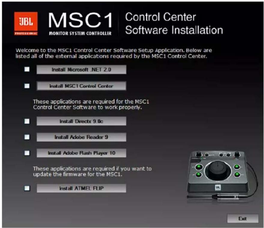
MSC1 Control Center Software Installation Menu
From CD-ROM:
- Insert the supplied CD-ROM in an available CD-ROM drive. The installation application should launch automatically.
- In the event that the installation doesn't auto-launch, from the Start Menu, click RUN.
- Click BROWSE.
-
Locate the drive containing the MSC1 Control Center Software CD-ROM.
-
Click on the file named MSC1_Application_Installer.EXE and the MSC1CC Installation Application will open.
If the Installer will not open after attempting to launch it:
A. From the Start Menu Click RUN.
B. Click BROWSE.
C. Locate the drive containing the MSC1 Control Center Software CD-ROM.
D. Navigate to the MSC1 Installer Folder.
E. Find and click on the file named "dotnetfx.exe" and this will begin an Install of MS.NET framework 2.0.
F. When the installation is complete, attempt to launch the MSC1 Installation software again.
- There are several software components, listed in the MSC1CC Software Installation Screen, required to successfully run the MSC1 Control Center.
The MSC1 Installation Software checks your system and determines the current availability of each component. A checkmark appears in the check box adjacent to a given component's launch button if it is determined the component is already installed. Therefore a component that has a checkmark in its check box does not require installation.
-
If you attempt to load an application previously installed on your computer, the instructions will ask you if you would like to repair, uninstall, or cancel the installation. At this point you should cancel the installation of that particular application.
-
Going down the list, for each component without a checkmark, press the corresponding launch button to begin installation.
-
During the MSC1 Control Center Software installation, a launch icon is placed on the desktop.
-
The DirectX 9.0c installation will ask you to choose a directory for the installation. Select any location on your C: Drive. For example, create a directory called C:\directx-9c on your hard drive and select this location for the install.
-
The ATMEL FLIP installation will ask you if you want to restart your machine. If you select NO, then as you exit the MSC1CC Installation you will be reminded that you must restart your computer before using the MSC1CC Software.
-
After you restart your computer, you can launch the MSC1 Control Center.
To install from a downloaded .ZIP file:
-
Copy the file to the desktop
-
Extract the contents using an archive application. To maintain the correct file structure, you must use the "Extract" function of the archive application. Proceed to step #5 above.
To Uninstall the MSC1 Control Center:
Launch Control Panel->Add or Remove Programs. From the “Currently Installed Programs” List, Find and highlight “MSC1 Control Center.” Then Click “Remove.”
NOTE: From time to time, JBL will issue software updates that enhance MSC1 Control Center functionality. If your computer is connected to the internet, software updates can be downloaded at www.jblproservice.com; otherwise you can obtain the update by contacting JBL Professional Customer Service at (800) 8JBLPRO (800-852-5776), Monday - Friday, 8am - 5pm P.S.T.
- Install the MSC1 Control Center Software following the procedure on pages 6.
- Connect the MSC1 power supply to an available wall outlet and then connect the MSC1 to your computer using the supplied USB cable.
- Launch The MSC1 Control Center Via the Desktop Icon.
- To power the MSC1 on or off, press the MSC1's Power Button or click on the Power Button image in the Software.
- To change subwoofer level, crossover frequency or polarity settings, click the SUB button in the software or press the MSC1 front panel SUB control. Make adjustments using the on-screen Sub controls. To view Subwoofer settings at any time, click on the SUB GRAPH tab.
- To apply high frequency and low frequency monitor EQ, click the EQ button in the software or press the MSC1 front panel EQ control. Make adjustments using the on screen EQ controls. To view EQ settings at any time, click on the EQ Graph tab.
- To enable MUTE click on the MUTE button in the software or press the front panel MSC1 MUTE control.
- To activate Room Mode Correction (RMC ^™ ) settings, click the RMC button in the software or press the front panel MSC1 RMC control.
- To perform RMC Calibration, click RMC Menu, RMC Calibration, and follow the on-screen instructions.
- To change the level of an individual speaker, click RMC Menu, RMC Alignment, and use your mouse to adjust the level slider, to the left of each speaker image. Note: Speakers levels are automatically adjusted during the RMC Calibration Procedure.
- To apply delay to an individual speaker click RMC Menu, RMC Alignment, and use your mouse to move the Delay level slider, to the right of each speaker image.
Following installation, a shortcut to the MSC1 Control Center Software is placed on your desktop and in your computer's Start Menu under Programs-> JBL Professional-> MSC1 Control Center.

MSC1 Control Center Icon
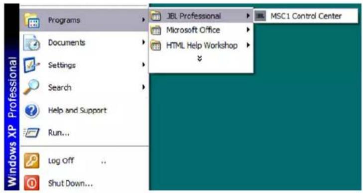
Start Menu Launch Icon
Note: Your MSC1 must be connected to your computer with the supplied USB cable and powered on before launching the MSC1 Control Center Software.
Prior to launching the MSC1 Control Center Software, make sure your MSC1 is connected to your
Note: To protect your speakers, it is good practice to complete audio connections with the MSC1 and all connected equipment powered off.
computer with the supplied USB cable and powered on. Then double-click on the desktop icon (or single-click on the Start menu icon) to launch the software. See the Features section on the following pages for details about all MSC1 Control Center Software display and menu options.

MSC1 Top Screen
As you can see, the MSC1 Control Center Top Screen consists of these main areas:
①. A Graphic Area, at the top of the screen
② A series of five Selector Tabs across center screen
The SUB Panel, to the left of the Virtual MSC1
. A "Virtual" MSC1, at bottom center
. The EQ Panel, to the right of the Virtual MSC1
⑥. The Message Bar beneath the five tabs
Note: When you launch the MSC1 Control Center Software, the Top Screen will reflect the current settings of the MSC1. If the MSC1 EQ and/or SUB controls are not illuminated, the EQ, SUB PANELS, and associated graphics will be grayed-out.
Let's take a closer look at each of the Control Center screen areas.
MSC1 Control Center Layout
Virtual MSC1
The lower center section of the MSC1 Control Center Software Top Screen is dedicated to display the "Virtual" MSC1.
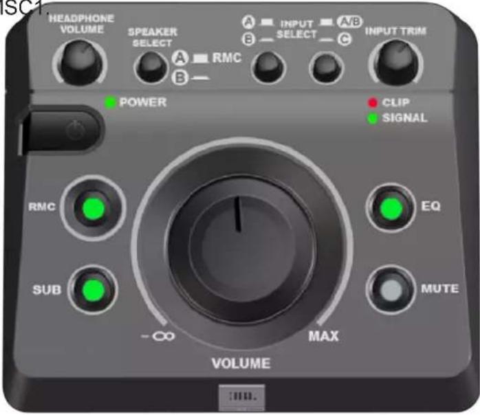
Virtual MSC1
The Virtual MSC1 displays status of these MSC1 front panel controls: SPEAKER SELECT, INPUT SELECT, RMC™, SUB, EQ, MUTE, and VOLUME position. As you make actual changes to these MSC1 front panel controls, they are instantly reflected in the Virtual MSC1. Status of The CLIP / SIGNAL LEDS, HEADPHONE VOLUME and INPUT TRIM controls are
Note: The RMC, SUB, and EQ controls do not work when the Speaker SELECT switch is set to B because unprocessed signal is always routed to the "B" SPEAKER OUTPUTS.
not displayed in software. The software features are static images.
What's more, you can turn on the actual MSC1 RMC, SUB, EQ, and MUTE controls—even power the unit on and off—from the Top Screen display. (There is a brief pause when powering
Note: All front-panel controls of the connected MSC1 remain fully functional even when the MSC1 Control Center Software is running.
on the MSC1 from the Top Screen as the computer communicates with the MSC1.)
MSC1CC Graphic Area
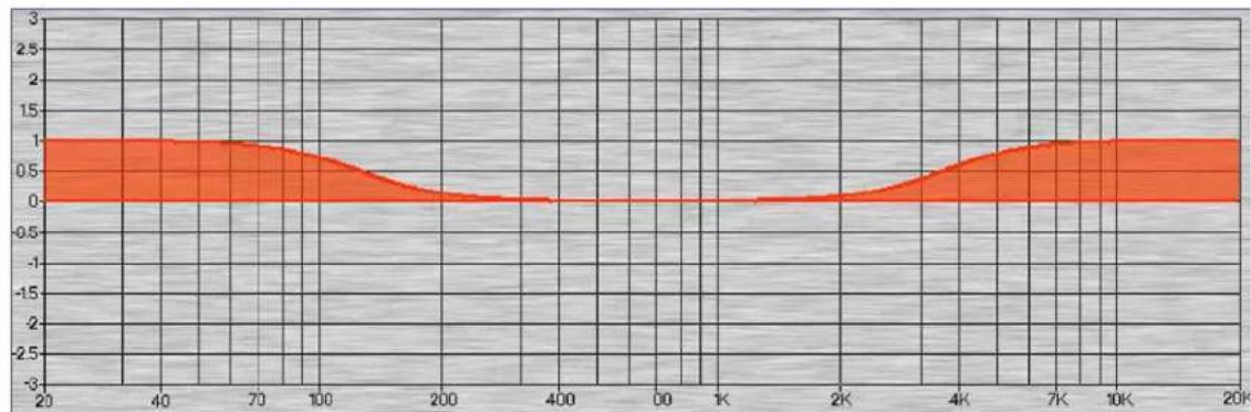
The upper area of the MSC1 Control Center Software Top Screen is used to provide graphic display of RMC™, SUB, and EQ settings when the associated tab is selected. When the respective controls on the MSC1 are not illuminated the graphs will be displayed in gray instead of full color. The example below shows the difference between displays when the EQ is On (the MSC1 EQ control is illuminated) versus Off (the MSC1 EQ control is not illuminated).
area
| x | y | | ---- | ----- | | 20 | 1.0 | | 40 | 1.0 | | 70 | 1.0 | | 100 | 0.8 | | 200 | 0.2 | | 400 | 0.0 | | 600 | 0.0 | | 800 | 0.2 | | 1000 | 0.5 | | 2000 | 1.0 | | 4000 | 1.0 | | 6000 | 1.0 | | 8000 | 1.0 | | 10000| 1.0 | | 20000| 1.0 |EQ On

area
| x | y | | ---- | ----- | | 20 | 1.0 | | 40 | 1.0 | | 70 | 1.0 | | 100 | 0.5 | | 200 | 0.0 | | 400 | 0.0 | | 600 | 0.0 | | 800 | 0.5 | | 1K | 1.0 | | 2K | 1.0 | | 4K | 1.0 | | 7K | 1.0 | | 10K | 1.0 | | 20K | 1.0 |EQ Off
MSC1CC Selector Tabs

flowchart
graph TD
    A["RMC Menu"] --> B["7"]
    C["RMC Graph"] --> D["8"]
    E["SUB Graph"] --> F["9"]
    G["EQ Graph"] --> H["10"]
    I["MSC1 Options"] --> J["11"]
Selector Tabs
Five tabs are provided across the center of the MSC1 Control Center Software Top Screen, as follows:
. RMC™ Menu – Click on this tab to access the RMC Menu.
. ⓊRMC Graph – Click on this tab to display RMC filter settings.
. SUBGraph - Click on this tab to display SUB settings.
-
Graph - Click on this tab to display EQ settings.
-
MSC1 Options – Click on this tab to access the following system features and functions: Help Tips, Store or LOAD EQ Configurations, update the MSC1 Firmware, restore MSC1 factory default settings, or display MSC1CC Software system information (software / firmware version numbers, tech support phone number, JBL website link.)
MSC1CC Message Bar
6 MSC1 Control Center finished linking to Controller.
Every time a control is moved within the MSC1 Control Center Software, commands are generated and sent to the MSC1 via USB. The Message Bar displays these commands as they occur. Only the most recent command is displayed; however, you can view the history of previous commands by clicking on the Message Bar and using the up and down arrow keys on your computer keyboard, or the mouse scroll wheel.
SUB
Pressing the SUB control on either the virtual or physical MSC1 so that it is illuminated activates the SUB PANEL located to the left of the Virtual MSC1, as shown in the illustration below. After Pressing the SUB button audio is muted for 12 second while subwoofer settings are loaded.

Sub Panel Closed Sub Panel Open

Note: The SUB control does not work when the SPEAKER SELECT switch is set to B because the subwoofer is only available for the speaker system connected to the "A" SPEAKER OUTPUTS.
In this panel, you can increase or decrease the level of a connected subwoofer by as much as 10 dB, in increments of 0.25 dB; invert the subwoofer polarity; and select any of three crossover frequencies (60 Hz, 80 Hz, or 120 Hz).
Gain and Sub Polarity settings in this panel can be modified by clicking the parameter with your mouse and then dragging (left or right) with the mouse, using the mouse scroll wheel or by using the arrow keys (up-down or left-right) on your keyboard while the mouse pointer is centered over the control.
Crossover frequency can be changed by clicking on the desired button.
Note that whenever any of these parameters are changed, the SUB control on the physical MSC1 flashes to indicate an update has been received. Also the graphic area in the upper area of the software screen automatically displays the SUB graph, reflecting real-time changes. Subwoofer level is displayed in Green; the subwoofer response below the crossover frequency is displayed in Red when subwoofer polarity is 0^ (Normal) or in Light Blue when the polarity is set to 180^ (inverted). The left and right speaker response above the crossover frequency is displayed in Dark Blue.

area
| Sub Graph | Red Area | Green Area | Blue Area | | --------- | -------- | ---------- | --------- | | 20 | 0 | 6 | 0 | | 40 | -12 | 5 | 0 | | 70 | -6 | 3 | 0 | | 100 | -2 | 1 | 0 | | 200 | -12 | 0 | 0 | | 400 | 0 | 0 | 0 | | 700 | 0 | 0 | 0 | | 1000 | 0 | 0 | 0 | | 2000 | 0 | 0 | 0 | | 4000 | 0 | 0 | 0 | | 7000 | 0 | 0 | 0 | | 10000 | 0 | 0 | 0 | | 20000 | 0 | 0 | 0 |The subwoofer is balanced relative to the main speakers during the RMC ^™ Calibration process. However, subwoofer level can be adjusted at any time using the SUB level control.
The SUB POLARITY should be set to the value that yields the greatest perceived low frequency level when listening at the mix position. Normally, when the subwoofer and main speakers are the same distance from the mix position, the best blend of the subwoofer and main speakers is achieved when SUB POLARITY is set to 0^ .
The SUB CROSSOVER determines the frequency at which signal is divided and sent to either the subwoofer or the main speakers. We recommend using the 80Hz setting as this gives the best results in most conditions. Audition the other options to suit your listening conditions and preference. See the documentation accompanying your speaker system for subwoofer crossover recommendations. If your main speakers include a high pass filter, this should be bypassed when used with the MSC1. Also, if your subwoofer includes a crossover control, it should be set to “full range” or the highest available frequency setting when used with the MSC1. If the subwoofer has an LFE (Low Frequency Effects) Input use this input when connecting the subwoofer to the MSC1. Refer to the documentation accompanying your speaker system for more information.
Note: When the SUB crossover frequency setting is modified, audio is muted for several seconds while the new settings are loaded in the MSC1.
The current settings for the SUB features are stored in the MSC1 and remain in memory after disconnecting the MSC1 from the computer, turning the MSC1 off, or disconnecting the power source. Whenever the MSC1 is powered on, your latest settings are stored, until you modify the settings using the software.
EQ
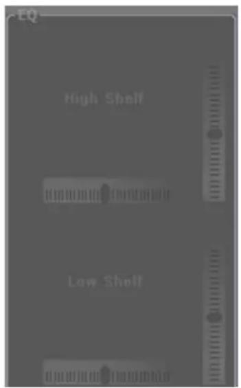
Pressing the EQ control on either the virtual or actual MSC1 so that it is illuminated activates the EQ PANEL located to the right of the Virtual MSC1, as shown in the illustration below. After Pressing the EQ button, audio is muted for 12 second while EQ settings are loaded.
EQ PANEL
EQ Panel Closed

EQ Panel Open
Note: The EQ control does not work when the SPEAKER SELECT switch is set to B because unprocessed signal is always routed to the "B" SPEAKER OUTPUTS.
This panel allows you to create custom dual-band equalization ("EQ") settings for the speakers connected to the MSC1 "A" SPEAKER OUTPUTS. Two shelving-style filters with independent controls are provided for the boost or attenuation of high frequencies (High Shelf) and low frequencies (Low Shelf).
To change equalization settings, simply use your mouse to “grab” any of the four controls – HIGH SHELF FREQUENCY, HIGH SHELF GAIN, LOW SHELF FREQUENCY, or LOW SHELF GAIN – and then move the on-screen slider to set the value. Alternately, you can select the parameter with your mouse and then use the arrow keys (up-down or left-right) on your keyboard or the mouse scroll wheel. Note that when EQ settings are changed, the EQ control on the physical MSC1 fl ashes to indicate that updates have been received. Also the graphic area in the upper area of the software screen automatically displays the EQ graph, showing parameter changes in real-time. If the “A” SPEAKER OUTPUTS are selected and playing audio, EQ changes will be heard as parameters are adjusted.

area
| x | y | | ---- | ----- | | 20 | 1.0 | | 40 | 1.0 | | 70 | 1.0 | | 100 | 0.8 | | 200 | 0.2 | | 400 | 0.0 | | 600 | 0.0 | | 800 | 0.5 | | 1000 | 1.0 | | 2000 | 1.0 | | 4000 | 1.0 | | 6000 | 1.0 | | 8000 | 1.0 | | 10000| 1.0 | | 20000| 1.0 |EQ Graph
Note: Rapid manipulation of the EQ FREQUENCY and GAIN controls may require additional time for parametric changes to take effect. This is normal, and can be alleviated by slowing movement of the controls.
Note: To compare your custom settings with the un-equalized (flat) response, simply click the EQ control to activate or bypass EQ settings.
Twenty-eight different High Shelf Frequency values are available, from 2.5 kHz to 17 kHz. Frequencies above the selected High Shelf Frequency value can be boosted or attenuated by ±3 dB, in increments of 0.25 dB.
Thirty-two different Low Shelf Frequency values are available, from 34 Hz to 1.104 kHz. Frequencies below the selected Low Shelf Frequency value can be boosted or attenuated by ±3 dB, in increments of 0.25 dB.
The current EQ settings are stored in the MSC1 and remain in memory after disconnecting the MSC1 from the computer, turning the MSC1 off, or disconnecting the power source. Whenever the MSC1 is powered on, your latest settings are stored, until you modify the settings using the software.
MSC1 Options
Clicking on the MSC1 OPTIONS tab displays the following window, which allows you to access additional features and information.

Options Menu
Note: The Options Menu can be moved anywhere onscreen by clicking and dragging the title bar.
Help Tips
Useful tips can be displayed about a given control by positioning the mouse over the control. To activate or deactivate this feature, click the box next to "Select to show help tips when mousing over a control."

Help Tips
EQ Configuration
From the MSC1 Options Menu, click (EQ Configuration) to open the EQ Configuration Options Menu. This menu allows you to save and recall MSC1 EQ Configurations to/from your computer's hard drive.

EQ Configuration Menu
Store EQ Configuration
To store custom EQ settings for the High and Low Shelf Filters, click (Store Configuration File). A Save-File Dialog will appear, allowing you to store your custom EQ settings as a file on your computer's hard drive.

Store EQ Configuration Dialog
Load EQ Configuration
You can also load stored EQ settings into the MSC1 memory. To do this, click on the (Load Configuration File) button. A caution appears indicating that you are about to overwrite the current EQ settings. After clicking (Proceed), a Load-File Dialog will appear. Simply browse to find the location of the EQ file you wish to load and click (Open) to begin loading the EQ settings.

Load EQ Configuration Caution

Load EQ Configuration File Dialog
Firmware Update
From time to time, JBL may issue a firmware update to correct a problem or provide enhancements to MSC1 functionality. This feature requires special configuration procedures prior to initial use; See Updating MSC1 Firmware for detailed information.
Factory Reset
Selecting this option will restore all settings in the connected MSC1 to original factory settings.
Note: The factory reset procedure does not affect the currently loaded version of firmware in the MSC1.

Factory Reset Caution
The device's memory can be restored to default factory settings. A factory Reset can be performed either from the MSC1 Control Center or manually from the front panel of the MSC1 (see the MSC1 Owner's Manual for the manual factory reset procedure.)
After clicking (Factory Reset) in the MSC1 Options Menu, a caution appears indicating that you are about to replace all current settings in the MSC1 with factory default settings. Click (Proceed) to replace all current MSC1 settings with Factory Default settings, otherwise, click (CANCEL). If you select (Proceed) there is a short pause while the settings inside the MSC1 parameters are reset to Factory Default settings. MSC1 LEDs will flash for approximately 15 seconds. Once the LEDs stop flashing, the MSC1 will link to the MSC1 Control Center Software.

Factory Reset – Blank or Normal
A pop-up will appear asking if the unit should be reloaded with the most recent MSC1 Control Center feature data (NORMAL) or returned to the factory default settings (BLANK). At this point you can choose to restore the most recent settings or to load factory default settings.
About MSC1 Control Center
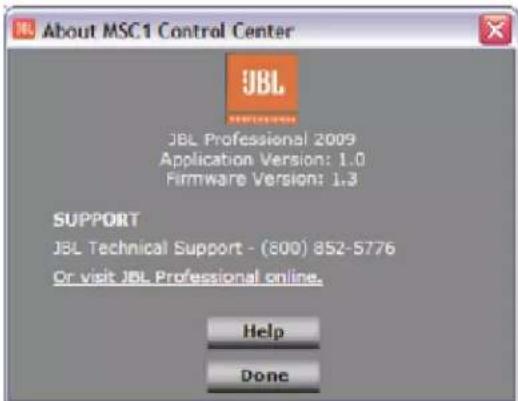
Selecting this displays the current version number of MSC1 firmware and MSC1CC software. This window also provides a JBL Pro web link and phone number for technical support.
About MSC1 Control Center Menu
What is JBL RMC™ Room Mode Correction?
A JBL first, the RMC Room Mode Correction system includes everything needed to analyze low frequency problems in your room and restore low frequency accuracy at your mix position. RMC is included in JBL's premium LSR6300 series and LSR4300 Series studio monitors. The MSC1 makes RMC affordable while extending RMC capabilities to any speaker system.
What Room-Related Problems does RMC Address?
There are two types of acoustic problems common in the small production environment, particularly those that have not been professionally designed. In the low bass region, your ROOM affects what you hear Rooms resonate at low frequencies. This resonance is the result of standing waves or room modes. The presence of room modes can give a false impression of bass response at the mix position, and lead even an experienced mix engineer to make the wrong decisions while mixing audio. A room mode is caused by the room's geometry. In a typical project studio, the strongest room modes exist at 60 Hz and below. When your speakers play bass frequencies, say from a bass guitar, the room may resonate at the frequency of the room mode. The effect is a boomy sound that continues to ring even after the note has stopped playing. This may be perceived to be a problem in the mix, when actually it is a problem in the room. Depending on where the speakers are placed and where you are sitting, it can be very dramatic. Without correction, you might choose to attenuate, limit or equalize bass signals that excite the problem. But the problem is not the mix. It is the way the mix sounds in this specific room. By changing your mix, it will sound bass-light everywhere else it is played.
Professional studios eliminate this problem by constructing bass traps in the control room. Since low frequency wave lengths are very long (50 Hz equates to a 22-foot wavelength) it takes a lot of space and mass to absorb the frequencies that excite these room modes. Most studios have neither the space nor budget to build real bass traps. Alternatively, putting absorptive material on the walls does not help these low frequency problems.
In addition to room modes, a speaker's proximity to walls and your mixing work surface can cause reinforcement of upper bass frequencies, and other sonic coloration which may adversely affect mix balances.
JBL RMC Room Mode Correction in the MSC1 is an analyzer that measures the presence of these problems and applies corrective filters that can dramatically improve the bass performance. RMC can make a big difference in problematic rooms. Once your speaker system has been properly calibrated, you'll experience superior clarity at the mix position; achieving balanced mixes comes with greater ease. Mixes produced in an RMC-tuned room sound right when played on other systems.
The MSC1 Control Center Software is required in order to take advantage of the MSC1 RMC feature. Using the software, it is possible to calibrate two speakers and, optionally, a subwoofer connected to the "A" SPEAKER OUTPUTS of the MSC1. In addition, the software permits manual adjustment of individual speaker and subwoofer levels, and subwoofer polarity, as well as application of delay to all speakers in order to compensate for differences in distance from the mix position. Once the system is calibrated, connection to a computer is no longer required.
Fundamentals of the RMC™ Calibration Procedure:

flowchart
graph TD
    A["Microphone"] --> B["MSC1"]
    C[" Speakers"] --> B
    D[" External Audio Interface"] --> B
    E[" Computer running MSC1 Software "] --> B
    B --> F["Speaker 1"]
    B --> G["Speaker 2"]
    B --> H["Speaker 3"]
    B --> I["Speaker 4"]
RMC Calibration Concept for Audio Interface
The RMC Calibration Procedure is a series of steps that culminate with the measurement of the speaker system in the room, and configuration of corrective filters in the MSC1 that tackle low frequency problems in the room. During the process, Control Center Software generates and analyzes reference signals used to identify the acoustic conditions in the room. The essential components in the audio path include a computer, a sound card or external Audio Interface, the supplied calibration microphone and cables. Since not all computers and sound cards are alike, to ensure the speaker measurements are valid, every component in the audio path too must be measured. The RMC Calibration Procedure guides you in optimizing the audio path of your system. Each section of the calibration process is clearly explained in the software using on-screen instructions and animated illustrations. The software provides a step-by-step process to evaluate and optimize the audio path. Once the audio path is optimized the speaker system is measured and calibrated by the Control Center using JBL's third generation RMC technology.
This is how the process works:
-
During the RMC process, calibrated reference "test" signals are generated by the Control Center Software output via the computer soundcard or Audio Interface. The signals are played through the MSC1 and reproduced by a connected speaker system.
-
Next, the acoustic response of each speaker is captured by the RMC Calibration microphone connected to the MSC1. The microphone signal is sent to the computer soundcard or Audio Interface input and on to the computer where the RMC algorithm in MSC1 Control Center analyzes the signal. Control Center then calculates and transmits coefficients for corrective filters to the MSC1. The filters are inserted in the signal path to the speaker outputs to "tune" the speaker system to work in harmony with the room.
A robust signal free of coloration is required for accurate measurement. To achieve this, the computer's Audio Interface and the computer itself must be properly configured to ensure the audio is unaffected by signal processing that may exist in the system. In addition, successful calibration requires the signal-to-noise performance of the entire audio path is optimized prior to measurement of the speakers. Control Center guides you in the steps required to achieve this.
To ensure success:
- The test signals originating at the computer must be reproduced by the speakers at an adequate volume. The software will guide you in setting playback levels to achieve a healthy test signal.
- The test signals captured by the microphone and analyzed by the software must be ample enough to minimize the contribution of noise in the room and the system itself. Therefore, the software will monitor the noise floor and input sensitivity of the recording channel and will guide you in making required adjustments.
- With your participation, the RMC™ Calibration Procedure ensures required conditions are met prior to calibrating your speakers. MSC1 Control Center will notify you of any conditions that require attention and may ask you to review a prior step to correct any set up errors. After resolving any issues, you can return to the current step.
Caution: Very loud playback volumes can damage hearing and speakers. While performing steps using test signals, never adjust system volume to produce a playback level that is audibly painful. Familiarize yourself with the following procedures. If playback level becomes audibly uncomfortable, stop the test. Reduce the setting of the MSC1 Input Trim Control and repeat the previous steps.
RMC™ Menu
The RMC Menu allows access to the RMC features and procedures. To access the RMC Menu, click the (RMC Menu) Selector Tab. To exit the RMC Menu, click the (Exit RMC Menu) Selector Tab. The RMC Menu has two panels, the RMC Calibration Panel and the RMC Alignment Panel accessed by clicking on the respective buttons.

RMC Menu
The RMC Calibration Panel guides you through the RMC Calibration Procedure that tunes connected speakers to the room. The RMC Alignment Panel allows you to fine-tune speaker settings, adjusting level and time delay of individual speakers. The panel offers enabling the alignment features.
Starting RMC Calibration
To initiate RMC Calibration from the MSC1CC Top Screen, enter the RMC Menu by clicking (RMC Menu), and then click (RMC Calibration).
This RMC Calibration Procedure involves a series of steps and instructions that allow you to perform RMC Calibration.
RMC™ Screen Sections
Each screen in the RMC Calibration Procedure is divided into 4 different areas: the Graphics Display Area, Instruction Area, Control Area, and RMC Timeline Area.

Typical Screen in the RMC Calibration Procedure
⑫ Graphics Display Area: This first area displays graphics and animated images that highlight the current step of RMC Calibration.
Instruction Area: This area provides the detailed text instructions of the current RMC step in the form of White text. **Text color issue
Controls Area: This interactive area contains all of the buttons, meters, and sliders required to configure and verify your audio path, during the RMC Calibration Procedure.
⑮ RMC Timeline Area: The bottom area of the screen is a graphic indicating completed and remaining steps in the RMC procedure.
RMC™ Navigation and Information Controls
The RMC Navigation and Information Controls allow you to advance through the instructions of the RMC procedure and provide access to additional help information. These controls are available throughout the RMC Calibration Procedure.

flowchart
graph TD
    A["REPLAY"] --> B["<BACK"]
    B --> C["NEXT>"]
    C --> D["SKIP >>"]
    E["HELP"] --> F["CANCEL"]
    G["16"] --> A
    H["21"] --> E
    I["17"] --> B
    J["18"] --> C
    K["19"] --> D
    L["20"] --> F
RMC Navigation and Information Controls
⑯ REPLAY: Clicking this button rewinds and plays the current animation from the beginning.
⑰ BACK: Allows you to return to the prior step in the RMC Calibration Procedure.
⑱ NEXT: Takes you to the next step in the RMC Calibration Procedure.
19 SKIP: Allows you to bypass a group of related steps. This is useful when navigating through a section with which you are already familiar; foregoing detailed description and allowing you to move to the next step that requires action.
⑳ CANCEL: Exits the RMC Calibration Procedure and returns you to the RMC Menu.
21 HELP: Provides detailed information relevant to the current step of the RMC procedure.
RMC™ Test Controls
The RMC Test Controls appear in certain RMC steps that require user-adjustment of audio levels, during the RMC Calibration Procedure. These controls start and stop the audio test signals as well as provide control over audio levels and display status information.

RMC Test Controls
22 START: Clicking this button activates the audio test signal.
②3 STOP: Clicking this button terminates playback of current test signal.
24 Output Level Slider: This control is used to modify the level of the test signals output by the computer during RMC Calibration.
25 Level Meter: This area displays the currently-measured level in dB (relative to 0 dB full scale) and changes color to indicate if the currently displayed signal level meets test requirements. The bar in the meter is Red in color if the measured input signal is found to be too low in level, (less than -20 dB). The bar is Purple if the measured input signal is found to be too high (above -8 dB). The bar is Green when the measured input level is adequate (between -20 dB and -8 dB) (indicating a level that is just right).
26 Level Indicator: This area displays a numeric representation in dB (relative to 0 dB full scale) of the current level measured at your computer's input channel. Whenever an audio test signal is playing, the two dots at either end of the Indicator flash indicating the measured audio level is actively being displayed.
27 Input Level Slider: This control is used to change the input level (sensitivity) of the selected input channel of your computer. This control appears only when using the computer's Internal Soundcard.
RMC™ Other Controls
These RMC Controls are displayed only in certain steps of the RMC Calibration Procedure.


28 29 Confirm/Retry Buttons
Yes/No Buttons\$
28 CONFIRM: Selects the currently listed input and output audio drivers from the Audio Driver Drop-Down Menus.
⑲ RETRY: Causes the computer to check your computer for connected soundcards and External Audio Interfaces, re-populating the current Audio Driver Drop-Down Menus.
③0 YES: Clicking this causes previous test settings to be utilized for RMC.
③1 NO: Clicking this ignores previously stored data enabling the option to complete the entire RMC process.

32 Soundcard Drop-Down Menu
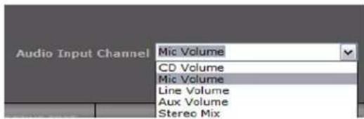
③3 Input Channel Drop-Down Menu

③4 Speaker Configuration Drop-Down Menu
32 Soundcard Drop-Down Menus: This box is populated with all the input and output drivers of detected soundcards and External Computer Audio Interfaces connected to your computer.
33 Audio Input Channel Drop-Down Menu: This box is populated with the input channel options of your selected soundcard or Audio Interface.
34 Speaker Configuration Drop-Down Menu: This box allows you to specify the configuration of the speaker system you are using.
RMC™ Timeline Area

flowchart
graph LR
    A["COMPUTER SETTINGS"] --> B["35"]
    C["Connections: Internal Step 3"] --> D["36"]
    E["SET TEST LEVELS"] --> F["37"]
    G["LOOPBACK TEST"] --> H["38"]
    I["AUDIO RECONNECT"] --> J["39"]
    K["SPEAKER CONFIGURATION"] --> L["40"]
    M["RMC CALIBRATION"] --> N["41"]
RMC Timeline
The RMC Timeline is a visual representation of the entire RMC Calibration Procedure. Each stage of the RMC Calibration Procedure is illustrated as a section in the RMC Timeline. There are seven sections in the RMC procedure, beginning with verification of your system set up and ending with the measurement and calibration of your speaker system in the room. As you progress in the RMC procedure, the Current section of the procedure is highlighted in Green. The title of the Current section is printed in this Green box. Boxes for Completed sections appear in Light Gray, while the boxes for pending sections appear in Dark Gray. You can click on these boxes to view descriptive information for RMC Calibration Procedures that have been completed.
Section 0: Getting Started
This section does not appear on the timeline. This introductory section specifies the requirements and equipment you'll need to begin the RMC Calibration Procedure. In addition, this section provides experienced users the opportunity to skip some of the more detailed instructions.

Section 1: Computer Settings
Various computer settings including selection of soundcard and audio drivers are made here.

Section 2: Connections
The hardware within your system is properly connected and configured.

Section 3: Set Test Levels
Audio test signals are utilized to adjust the gain structure of your audio path.

Section 4: Loopback Test
Connections are and internal measurements are made to characterize the audio path of the computer and soundcard or Audio Interface.
⑲ Section 5: Audio Reconnect
Hardware connections are restored to their previous state.
④0 Section 6: Speaker Configuration
Your exact speaker configuration is selected.
④1 Section 7: RMC™ Calibration
In the final section the speakers in your room are acoustically measured, the Control Center calculates RMC filter coefficients which are loaded into the MSC1.
RMC Calibration Procedure Instructions:
This reference section of the User's Guide includes a summary of each step in the RMC procedure. The following pages include the instructions, illustrations and displays you will see in the software, when performing the RMC procedure. Additionally, this section includes the text you will see if you click the on-screen (HELP) button in any step of the procedure.
RMC™ Timeline Section 0: Getting Started
The fundamentals of RMC are given in this first section. We recommend that Control Center Software is open on your computer and you refer to related screen for each RMC step in the User's Guide.
Getting Started, RMC Introduction:

RMC Introduction
On-Screen Instructions: "At any time during the RMC process, you can Click (HELP) below for information or assistance. The (REPLAY) button allows you to repeat the current movie. (CANCEL) exits the RMC procedure and returns you to the RMC Menu. Click (NEXT) to proceed."
Note: This step provides an explanation of the RMC Calibration Procedure.
The following instructions allow you to take advantage of the MSC1's Powerful RMC Room Mode Correction Capability and guide you through steps required for RMC Calibration. In the procedure your computer uses this software to measure the room and send corrective filters to the MSC1. Since all computer hardware, sound cards, and computer audio interfaces are not the same, an essential part of the procedure measures the complete audio path of your system, and guides you in setting your computer, audio interface and other hardware to nominal settings. Once your system is “pre-calibrated,” the actual RMC Calibration portion of the procedure is fast. Also, once your computer hardware is pre-calibrated, unless you make significant changes to the system, you can repeat RMC Calibration at any time without having to repeat measurement and set up of your computer hardware.
Getting Started, RMC™ Preconditions
On-Screen Instructions: “Confirm that the system settings listed above are achieved before continuing. Click (NEXT) to proceed.”
Note: The requirements that follow pertain only to the RMC Calibration Procedure. Once RMC Calibration is complete, you may reconfigure your system as needed for normal use.
The following system settings are required before proceeding:
• The Computer is on.
• The MSC1 is powered on with no audio components attached.
• All MSC1 supplied accessories are available.
- Suitable Cables (not supplied) are available for connection of the MSC1 to a speaker system; 6.5mm (1/4 inch) to: 6.5mm, or male XLR.
- If the system includes an External Audio Interface, it is connected to the computer (via USB, fire wire, etc.), powered on, and functioning properly (drivers are loaded and the system is passing audio with no issues).
- To protect speakers, power on all connected audio components prior to powering on speakers and/or external power amplifier. Power off speakers and/or external power amplifiers prior to powering off connected components.
Getting Started, RMC™ Connector Legend

RMC Connector Legend
On-Screen Instructions: "Make sure that the items shown within the color-coded icons are readily available. Click (NEXT) to proceed."
Note: All items required for completing RMC Calibration are illustrated here. Cables required to connect speakers to the MSC1 Outputs are not included with the MSC1. The use of balanced connectors and cables is strongly recommended for best system performance.
All of the cables, connectors and accessories needed to run RMC are illustrated on this page for reference. For easy reference, different types of connections are color-coded throughout the procedure.
Green icons are used to specify cables used to connect audio components to the Inputs of the MSC1. Blue icons represent the cables used when connecting speakers to the outputs of the MSC1. The Red icon refers to the RMC Microphone connection to the MSC1. The Purple icon is used to specify the cable required to connect signal from the MSC1 to your sound card or computer Audio Interface input. The Gold icon represents the USB connection.
Getting Started, Previous RMC™ Test Settings?
On-Screen Instructions: "It appears RMC Calibration has been previously performed on this computer. Use existing test settings? For more information, Click (HELP)."
Note: If you have previously run RMC on your system and you have not altered settings of system gain controls (MSC1 Volume, Input Trim, External Computer Audio Interface audio interface mic channel 1 input level, headphone output level, Direct/Computer Playback control *, you can Click (YES) to skip a number of sections of the procedure. For instance, if you have just finished running the RMC test, but are trying different speaker or subwoofer locations, you can Click (YES). If the RMC procedure details are unclear to you or if you have changed any part of your monitor path such as adding a new soundcard or audio interface, you should Click (NO) to ensure all steps are completed correctly.
If you have previously run an RMC Calibration on your computer, a number of parameters are saved in memory so that you can go through the RMC procedure faster the next time.
The parameters saved are your soundcard type (Internal Soundcard or External Audio Interface), Driver selections, audio input channel, Input and Output Level Slider settings. You will still be prompted to select your Speaker Configuration before running RMC Calibration. MSC1 and/or an External Audio Interface controls are assumed to be set correctly. If you are running similar RMC tests multiple times to try different speaker placements, listening distances, speaker configurations or adjustments in room treatment, using previous test settings will save time. If you are listening in a new location, a new room, using a different soundcard or Audio Interface, have changed MSC1 controller settings, or modified your speaker configuration, we recommend completing the entire RMC procedure.
RMC™ Timeline Section 1: Computer Settings
External Audio Interface or Internal Soundcard?
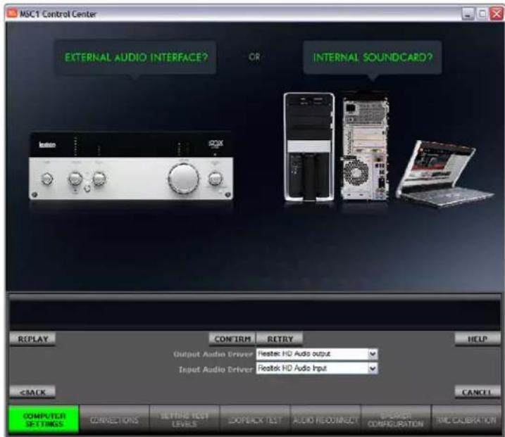
In this step, MSC1CC software gathers information about the audio devices connected to your computer. It then displays all input and output drivers found in the Audio Driver Drop-Down Menus shown in the RMC Control Area. This allows you to select the most appropriate audio path for the RMC procedure. Once you have confirmed the use of either the computer's Internal Soundcard or an External Audio Interface, the steps in the procedure are customized to configuration. The on-screen instructions and animations for the next four sections of the RMC Calibration Procedure differ based upon your choice of either an External Audio Interface or an Internal Soundcard.
What is an External Audio Interface?

Microphone Inputs for an External Audio Interface
An External Audio Interface is any device which adds audio inputs and outputs to your computer through Universal Serial Bus (USB) or Firewire (IEEE 1394) connections. These devices typically provide a number of Line and Microphone level inputs as well as multiple stereo and/or multi-channel outputs. Other features may include a variety of processing options, gain controls, and phantom power for microphones. The MSC1 is compatible with any External Audio Interface that follows standard USB or Firewire audio protocols. If you are using an External Audio Interface, you will be asked to adjust its gain controls during the RMC procedure.
What is an Internal Soundcard?
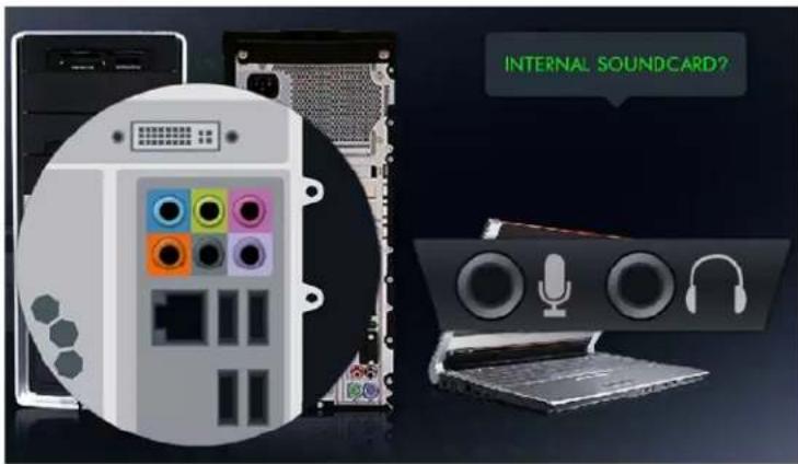
Input and Output jacks for an internal soundcard
An internal soundcard is any hardware which is integrated into a computer, either as part of the computer motherboard, or installed in an accessible card slot of the computer. An internal soundcard may provide a number of output and input jacks found in different locations on your computer. Volume is controlled by software for both the input and output. The above image shows a typical compliment of input and output jacks of laptop and desktop computers.
In the sections that follow, the User's Guide presents different sets of instructions for systems using an External Computer Audio Interface and systems using an Internal Soundcard.

Internal Soundcard instructions will look like this. Internal S.C. = Internal Soundcard

External Audio Interface instructions will look like this. External A.I. = External Audio Interface

Internal S.C. Computer Settings, Detection

Internal Soundcard Detection
On-Screen Instructions: "No External Audio Interface is detected. Select the drivers for your Internal Soundcard from the Drop-Down Menu below and Click (CONFIRM). Otherwise, Connect an External Audio Interface and Click (RETRY)."
Note: Select the name of the soundcard driver you wish to use for both Output Audio Driver and Input Audio Driver. Drivers for input and output should originate from the same soundcard.
If you have an External Audio Interface connected but you intend to use your computer's internal soundcard for RMC™, disconnect the External Audio Interface from the computer until the RMC procedure is complete. Once this is disconnected, Click on (RETRY) to update the options within the Drop-Down Menu. The Drop-Down Menu in MSC1 Control Center Software is the same drop down menu normally accessed through the Sound Folder in the Microsoft Windows Control Panel. For convenience, we have provided access to this menu within Control Center.

Internal S.C. Computer Settings, Input Selection

Internal Soundcard Recording Inputs
On-Screen Instructions: "Please select the appropriate Audio Input Channel from the Drop-Down Menu below, then Click (NEXT) to proceed."
Note: An Internal computer soundcard may have multiple input jacks for microphones, CD and DVD players, and other sources. The selections available in the Audio Input Channel Drop-Down Menu refers to the specific hardware input that you will use as the microphone input during RMC™.
In the Drop-Down Menu, you will see generic names for Audio Input Channels such as:
- Mic (Microphone), refers to the signal typically coming from a jack on the front or side of the computer. Sometimes a second "Rear Mic" input will be available, representing signal originating from a second microphone input on the rear panel of the computer.
- Line In, refers to the signal typically coming from a jack on the front or side of the computer.
- CD Player, refers to the signal typically coming from the internal CD-ROM of the computer.
- Aux, refers to signal from other auxiliary jacks, such as an "Aux" input, a TV tuner input, and/or a telephone line input.
- A Stereo or Mono Mix signal coming from the internal mixer software (a "mixer," as its name implies, combines the signal coming from multiple sources and sums it into an output).
The Drop-Down Menu is populated with all of the currently valid input sources. You must choose the one you plan to use for RMC Calibration. In most cases, this will be the Mic Jack or an input with a similar name.

Internal S.C. Computer Settings, Bypass Step 1
On-Screen Instructions: "Set Playback microphone to MUTE. Ensure that Master Volume and Wave channels are NOT MUTE. Select your recording channel from the available input sources. From the "Advanced" tab beneath this channel, Disable Mic Boost or Compression settings. The movie above illustrates an example of these settings. Click (NEXT) to proceed."
Note: The objective of this internal soundcard setup step is to ensure that the microphone input is selected on the incoming “Record” side but mute on the outgoing “Playback” side in order to avoid feedback within the soundcard.
During this step of the procedure the MSC1 Control Center Software will automatically attempt to open your “Master Volume” Mixer in Microsoft Windows XP or “Sound” Panel in Windows Vista. Many Internal soundcards have associated mixer software that allows each input to have an independent volume control (in the form of an on-screen fader).
In addition, there are often user-configurable settings for Microphone channels which if enabled, will compromise the accuracy of the RMC ^™ procedure. If your soundcard has settings for Mic Boost, Compression, Noise Suppression, Voice Recording, and/or Filtering, select the setting that disables these features.
For Windows XP, In order to manually navigate to the Window's "Master Volume" Mixer from the Windows Desktop:
- Click "Start",
- Move to "Settings",
- Click "Control Panel",
- Find and Click "Sounds and Audio Devices",
- Click the "Volume" Tab.
- Inside the "Device Volume" region, Click "Advanced...",
Once the Master Volume Mixer is Open: - Find and Click "Options" in the upper-left corner, then Select "Properties" from the menu.
-
In the Properties Panel, from the "Mixer device" Drop-Down Menu select the device that allows you to adjust volume for "Playback".
-
Click "OK" to open the Playback Mixer Controls.
- Verify that "Master Volume" and "Wave" channels are not set to MUTE.
- Verify that the "Mic Volume" (this refers to the Playback Microphone only) is Mute.
- Find and Click "Options", then Select "Properties" from the Menu.
- From the "Mixer device" Drop-Down Menu select the device that allows you to adjust volume for "Recording".
- Click "OK", to open the Recording Mixer Controls.
- Verify that "Mic Volume" is selected.
- Choose "Advanced" under this channel.
- Verify that the "Microphone Boost" is turned off and that all other effects are bypassed.
- At this time, close the mixer panels and proceed to the next RMC ^™ instruction.
For Windows Vista:
- Click "Start",
- Click "Control Panel", find and double click the "Sound" icon.
- Click the "Playback" tab and in the List of playback devices click the preferred one (typically called "Speakers") and then click "Properties" at the bottom of the panel.
- From the "Properties" panel click the "Levels" tab.
- This will bring up a list of channels associated with the selected device, from the list find the Microphone and verify that it is MUTE (this channel should contain a speaker icon that has a circle with a line through it when it is MUTE.)
- Click "OK" to save the change and close the "Properties" panel.
- Next from the "Sound" Panel click the "Recording" tab and find and click the preferred recording device (usually the "Microphone") and then click "Properties" at the bottom of the panel.
- From the "Properties" panel, click the "Levels" tab.
- Verify the selected device is NOT MUTE (the speaker icon within it should have sound waves coming from it) and move its "Microphone Boost" slider to 0 dB.
- Click "OK" to save the change and close the panel.
- Click "OK" to close the Sound Panel. Proceed to the next RMC instruction.

Internal S.C. Computer Settings, Bypass Step 2
On-Screen Instructions: "Search Windows Control Panel for your soundcard's Sound Management Software (names may vary). Ensure that all compressors, noise suppressors, equalizers, normalizers, and other effects are turned off. You may see a different image depending on your operating system. Click (NEXT) to proceed."
Note: Search your Control Panel and Program Files for applications related to your specific soundcard. These applications generally contain the name of the soundcard, or the brand of the soundcard. Open these applications to ensure that all filters and effects are disabled or bypassed.
In this step of the procedure the MSC1 Control Center Software automatically attempts to open your Control Panel. Internal Soundcards may contain advanced features and settings for noise suppression, equalization, normalization, compression, gain boost, and other effects that should be bypassed or disabled, before proceeding with RMC ^™ Calibration.
In order to manually navigate to the "Control Panel", from the Windows Desktop:
- Click "Start"
- Move to "Settings"
- Click "Control Panel"
Once "Control Panel" is open:
-
Find and Launch your Soundcard's Audio Control Manager; for example if you have a Realtek sound card the application is called "Realtek HD Sound Effect Manager."
-
Verify that all special effects (Noise suppression, equalization, normalization, compression, gain boost, filtering, etc.) are bypassed.

External A.I. Computer Settings, Detection

External Audio Interface Detection
On-Screen Instructions: "An External Audio Interface is connected. Select the drivers for your External Audio Interface from the Drop-Down Menu below and Click (CONFIRM). If you wish to use your Internal Soundcard, disconnect the External Audio Interface and Click (RETRY)."
Note: Select the name of the Audio Interface you wish to use. You should select input and output drivers from the same Audio Interface.
The RMC™ Calibration software detects all audio devices connected to your computer and displays the names of all input and output drivers found in the Drop-Down Menus of the RMC Control area. If you have an External Audio Interface connected but you intend to use your computer's internal soundcard for RMC, you must disconnect the External Audio Interface until the RMC process is complete. Once this is disconnected, Click (RETRY) to update the Drop-Down Menu options.

External A.I. Computer Settings, Bypass Step 1
On-Screen Instructions: “Search Windows Control Panel for your Audio Interface’s Sound Management Software (names may vary.) Ensure that all compressors, noise suppressors, equalizers, normalizers, and other effects are turned off. You may see a different image depending on your operating system. Click (NEXT) to proceed.”
Note: Search your Control Panel and Program Files for applications related to your specific Audio Interface. These applications generally contain the name or brand of the audio interface. Open these applications to ensure that all filters and effects are disabled or bypassed.
In this step the MSC1CC will automatically attempt to open your Control Panel. External Audio Interface manufacturers may include configuration applications which add functionality and options to the user such as Noise suppression, equalization, normalization, compression, gain boost, and other effects which should be bypassed or disabled.
In order to manually navigate to the External Audio Interface's Control Manager, from the Windows Desktop:
- Click "Start"
- Move to "Settings"
- Click "Control Panel"
- Find and Click on your Audio Interface's Audio Control Manager (For example, if you have a MOTU interface it will be called "MOTU Sound Effect Manager").
- Verify that all special effects (Noise suppression, equalization, normalization, compression, gain boost, filtering, etc.) are bypassed or set to Off.
RMC™ Timeline Section 2: Connections

Internal S.C. Connections

Internal S.C. Connections, Overview
On-Screen Instructions: "Click (NEXT) to view Step-by-Step instructions for the connections shown above. Otherwise, make the connections shown and then Click (SKIP)."
Note: Connections Overview shows all of the connections required at this time. Click (NEXT) to view step-by-step instructions on all connections. If necessary, refer to the LEGEND that illustrates all cables, connectors and accessories.
This procedure ensures that the hardware in your system is properly connected for the RMC Calibration Procedure. Note that two JBL LSR series speakers and subwoofer are shown for purposes of illustration. Note that any brand of speakers may be used and a subwoofer is not required to complete RMC Calibration.
The USB connection to the MSC1 is required at all times while using MSC1 Control Center Software.

Internal S.C. Connections, Step 1
On-Screen Instructions: "Using the supplied Phono Cable, connect the White Phono plug to the "C" Left Input and connect the Red Phono plug to the "C" Right Input of the MSC1. Connect the 3.5mm plug to the Headphone jack of your Soundcard. If your Soundcard has a 6.5mm jack, use the supplied Adaptor. Click (NEXT) to proceed."
Using the supplied Phono cable, connect your computer soundcard's headphone output (assumed to be stereo) to the MSC1 Input "C" jacks as shown. (Be sure to follow the color coding: Red plug to Red jack, White plug to White jack.) You may need to use the supplied female balanced 3.5mm (1/8 inch) to male balanced 6.5mm (1/4 inch) Adaptor if your soundcard's headphone output jack only accepts the larger connector.
Internal S.C. Connections, Step 2
On-Screen Instructions: “Attach the supplied Microphone Clip to a microphone stand and insert the MSC1 Calibration Microphone pointing upwards. The top of the Microphone should be at your ear height. Position the stand next to your listening position. Click (NEXT) to proceed.”
Note: You can position the microphone just to the side of the final listening position at this time, allowing you to remain comfortably positioned at your computer. You will have time to place the microphone in your exact listening position before the actual RMC™ Calibration begins. We highly recommend using a microphone stand. Holding the microphone in your hand while running RMC Calibration causes acoustic reflections off of your body to negatively affect results.
RMC results are best when the supplied omni-directional microphone is attached to a proper microphone stand using the supplied microphone clip. The microphone should be pointed straight up to ensure that the sound traveling across the surface of the capsule is consistent, regardless of speaker distance or direction from the microphone. The top of the microphone should be positioned at your ear height next to or near your listening position and remain there until you run RMC Calibration. You will have time to place the microphone in your exact listening position before the final RMC Calibration begins.

Internal S.C. Connections, Step 3
On-Screen Instructions: “Connect the supplied RMC™ Microphone 3.5mm plug to the MSC1 RMC MIC IN jack. Caution: Connecting a different microphone or product to this input may cause damage to the MSC1 or the connected product. Click (NEXT) to proceed.”
Caution: Connect only the supplied MSC1 RMC Microphone to the MSC1 MIC IN jack! Connecting other microphones or external equipment to the MSC1 MIC IN jack may cause damage to either the MSC1 or to the other equipment.
The RMC microphone is specifically designed to interface with the MSC1. Therefore, different microphones should not be substituted.

Internal S.C. Connections, Step 4
On-Screen Instructions: "Using the supplied 3.5mm Cable, connect one end to the MSC1 RMC MIC OUT jack and the other to your soundcard's Mic input. If your microphone input is 6.5mm, use the supplied Adaptor. Click (NEXT) to proceed."
The MSC1 RMC MIC OUT jack provides a conditioned mic-level signal intended for your
Note: The MSC1 buffers and amplifies the RMC MIC IN signal, and sends a balanced output signal from the RMC MIC OUT jack to your computer's soundcard input via the 3.5mm Cable (with the 3.5mm Adaptor if necessary.)
soundcard's Microphone input. The MIC OUT jack is the upper of the two 3.5mm (1/8 inch) connections on the rear panel of the MSC1. You may need to use the supplied female balanced 3.5mm (1/8 inch) to male balanced 6.5mm (1/4 inch) Adaptor if your soundcard's Microphone input only accepts the larger connector.

Internal S.C. Connections, Step 5
On-Screen Instructions: “Connect the MSC1 Speaker “A” left and right Outputs to studio monitor Left and Right Inputs using 6.5mm Cables. Connect the MSC1 SUB “A” Output to the input of a subwoofer (refer to studio monitor / subwoofer owner’s manual). Click (NEXT) to proceed.”
Note: For optimum performance and RMC™ results we recommend using balanced connections to your speakers. Although connections to two JBL speakers and a JBL subwoofer are shown, any brand of speaker may be used, and a subwoofer is optional. For information on balanced connections, refer to the LEGEND in this manual, or refer to your speaker's Owner's Manual.
To run an RMC Calibration, you will need 6.5mm cables to connect the MSC1 "A" SPEAKER OUTPUTS to your speaker system (these cables are not supplied). Audio connections may vary according to manufacturer and model of speakers. All MSC1 outputs are balanced 6.5mm (1/4 inch) type and we strongly recommend using the speaker's balanced inputs, if possible. Other equipment can be connected to the other MSC1 inputs (A and B) and outputs (B) at this time. However, make sure that you have made the required connection to the MSC1 (C) inputs for RMC Calibration. The rear panel of the MSC1 is clearly labeled. Confirm you have correctly connected the Left and Right inputs and outputs of connected equipment to the respective Left and Right connectors on the MSC1. If your soundcard has a "pan" function, it's a good idea to confirm left and right channels are properly patched to the MSC1. Panning full left should yield sound through your left speaker and sub only; while panning full right should yield sound through your right speaker and sub only.
If you are using passive speakers and external power amplifiers, whenever this guide makes reference to powered speaker inputs or level controls, substitute the power amplifier inputs and level controls.

Internal S.C. Connections, Step 6

MSC1 RMC™ Control Settings
On-Screen Instructions: "Set these MSC1 controls: (A.) SUB On. (B.) MSC1 VOLUME set to -∞ (Minimum). (C.) RMC Off. (D.) SPEAKER SELECT Switch is set to SPEAKER "A" Outputs (Up position). (E.) INPUT SELECT Switch is set to "C" (Down Position). (F.) INPUT TRIM set to Minimum (G.) EQ Off. (H.) MUTE is Not Enabled. Click (NEXT) to proceed."
Note: Ensure that all features of the MSC1 are set as directed. Even if the system does not include a subwoofer, set all controls as directed, including the SUB control.
The illustration in this step shows the MSC1 front panel settings required for RMC.
First, set both the INPUT TRIM and the MSC1 VOLUME to minimum (full counter-clockwise position) in order to protect your speakers from any loud pops, clicks, or noises while making connections and for the initial steps of RMC Calibration.
SPEAKER SELECT switch should be set to "A," which selects the "A" outputs. (RMC is available only for speakers connected to the "A" SPEAKER Outputs and the Subwoofer Output.)
The INPUT SELECT switch should be set to "C."
During RMC Calibration, the MSC1 MUTE control must be disabled and EQ must be turned off. The SUB button should be on whether or not a subwoofer is connected.

Internal S.C. Connections, Step 7

RMC ^TM Speaker Settings
On-Screen Instructions: "Check your studio monitors to confirm: (A.) Tone or EQ settings are Bypassed, Flat, or Normal. (B.) Speaker Volume control is set to Maximum. (C.) Speakers are Powered On. Click (NEXT) to proceed."
Note: Studio monitor features including equalizers, tone controls, and filters should be bypassed to allow RMC to collect unfiltered acoustic information from your system. All speakers should play at relatively the same relative volume. For the RMC Calibration Procedure, Speaker level controls should be set to produce equal output from all speakers and maximum overall volume.
Speaker systems may include equalization and tone control features to allow adjustment of frequency response. It is important to bypass features that affect frequency response or set them to "flat", or nominal values to ensure the effectiveness of the RMC Calibration Procedure. Following RMC Calibration, these frequency response controls can be restored to preferred settings.
Speaker volume controls should be set as close to maximum as possible while ensuring all of the speakers produce equal level. Speaker-to-speaker level differences of more than 10dB will cause display of an error message, requiring an adjustment of your speaker volume controls.

natural_image
Interior view of a computer setup showing external hardware and cable assembly (no text or symbols visible)External A.I. Connections

External A.I. Connections, Overview
On-Screen Instructions: "Click (NEXT) to view Step-by-Step instructions for the connections shown above. Otherwise, make the connections shown and then Click (SKIP)."
Note: Connections Overview shows all of the connections required at this time. Click (NEXT) to view step-by-step instructions on all connections. If needed, refer to the LEGEND containing all cables, connectors and accessories.
This procedure ensures that the hardware in your system is properly connected for the RMC ^™ Calibration Procedure. Note that two JBL LSR series speakers and subwoofer are shown for purposes of illustration. Note that any brand of speakers may be used and a subwoofer is not required to complete RMC Calibration.
The USB connection to the MSC1 is required at all times while using MSC1 Control Center Software.

External A.I. Connections, Step 1
On-Screen Instructions: "Using the supplied Phono Cable, connect the White Phono plug to the "C" Left Input and connect the Red Phono plug to the "C" Right Input of the MSC1. Connect the 3.5mm plug to the Headphone jack of your Audio Interface. If your Audio Interface has a 6.5mm jack, use the supplied Adaptor. Click (NEXT) to proceed."
Using the supplied Phono (RCA) cables, connect your computer External Audio Interface's headphone output to the MSC1 Input "C" jacks as shown. (Be sure to follow the color coding: Red plug to Red jack, White plug to White jack.) You may need to use the supplied female balanced 3.5mm (1/8 inch) to male balanced 6.5mm (1/4 inch) Adaptor if your External Audio Interface's headphone output jack only accepts the larger connector.

External A.I. Connections, Step 2

External A.I.RMC™ Settings
On-Screen Instructions: “On your Audio Interface confirm: (A.) Audio output cables are disconnected. (B.) Headphone output, microphone inputs, and interface output levels are set to Minimum. (C.) Phantom Power is turned OFF. Click (NEXT) to proceed.”
Note: Any mic or line input can be used for RMC as long as Phantom Power, and Mic Boost options are disabled. Do not use high impedance inputs, typically labeled "instrument/guitar."
Make sure that your external Audio Interface is not providing phantom power to the inputs before making any connections. Some Audio Interfaces include high impedance 6.5mm (1/4 inch) inputs allowing connection of electric guitars and other high impedance instruments. It is preferable not to use these inputs for RMC ^™ Calibration.
If you are using your External Audio Interface's main outputs, disconnect them in order to ensure that any sound associated with RMC Calibration is sent through the headphone output only.
Set all of your Audio Interface hardware's input and output level controls to minimum settings, to protect your system while connections are made.

External A.I. Connections, Step 3
On-Screen Instructions: “Adjust the Audio Interface Monitor Mix Control (also called Balance or Blend) to select 100% Computer Playback. To prevent feedback use this control to disable direct monitoring of the Input signal. Click (NEXT) to proceed.”
Note: This step prevents feedback from occurring within the Audio Interface. If you hear feedback or a distorted signal, check the position of this control. If you currently hear the microphone through your speakers, check the position of this control.
Audio Interfaces have a MIX control (sometimes referred to as DIRECT/PLAYBACK or BALANCE control) which adjusts the blend of signal coming from equipment connected to the Audio Interface inputs and the playback of audio coming from the computer. (Refer to your Audio Interface Owner's Manual for specific name and function of this feature.) Set this control to produce 100% computer playback, so only computer playback is sent to the audio outputs. This step prevents feedback from occurring within the Audio Interface. If you hear feedback or a distorted signal, check the position of this control. Once RMC is complete, you can set this control on your Audio Interface as needed for normal use.

External A.I. Connections, Step 4
On-Screen Instructions: “Attach the supplied Microphone Clip to a microphone stand and insert the MSC1 Calibration Microphone pointing upwards. The top of the Microphone should be at your ear height. Position the stand next to your listening position. Click (NEXT) to proceed.”
Note: You can position the microphone just to the side of the final listening position at this time, allowing you to remain comfortably positioned at your computer. You will have time to place the microphone in your exact listening position before the actual RMC™ Calibration begins. We highly recommend using a microphone stand. Holding the microphone in your hand while running RMC Calibration causes acoustic reflections off of your body to negatively affect results.
RMC results are best when the supplied omni-directional microphone is attached to a proper microphone stand using the supplied microphone clip. The microphone should be pointed straight up to ensure that the sound traveling across the surface of the capsule is consistent, regardless of speaker distance or direction from the microphone. The top of the microphone should be positioned at ear height and, for this particular step, placed next to or near your listening position, while you finish the RMC procedural instructions. You will have time to place the microphone in your exact listening position before the final RMC Calibration begins.

External A.I. Connections, Step 5
On-Screen Instructions: “Connect the supplied RMC Microphone 3.5mm plug to the MSC1 RMC MIC IN jack. Caution: Connecting a different microphone or product to this input may cause damage to the MSC1 or the connected product. Click (NEXT) to proceed.”
Caution: Connect only the supplied MSC1 RMC Microphone to the MSC1 MIC IN jack! Connecting other microphones or external equipment to the MSC1 MIC IN jack may cause damage to either the MSC1 or to the other equipment.
The RMC microphone is specifically designed to interface with the MSC1. Therefore, different microphones should not be substituted.

External A.I. Connections, Step 6
On-Screen Instructions: "Using the supplied 3.5mm Cable, connect one end to the MSC1 RMC™ MIC OUT jack and the other end to any of your Audio Interface Mic/Line inputs. If your microphone input is 6.5mm, use the supplied Adaptor. Click (NEXT) to proceed."
Note: If your Audio Interface has 2 or more balanced inputs, select any input which has a volume control, phantom power disabled, and is not a high impedance "instrument/guitar" input. If your audio interface allows stereo linking of inputs, set this feature to MONO.
The MSC1 RMC MIC OUT jack provides a conditioned mic-level signal intended for connection to your Audio Interface's Balanced Mic/Line input. The RMC MIC OUT jack is the upper of the two 3.5mm (1/8 inch) connections on the rear panel of the MSC1. You may need to use the supplied female balanced 3.5mm (1/8 inch) to male balanced 6.5mm (1/4 inch) Adaptor if your Audio Interface's Mic/Line input only accepts the larger connector.

External A.I. Connections, Step 7
On-Screen Instructions: “Connect the MSC1 Speaker “A” left and right Outputs to studio monitor Left and Right Inputs using 6.5mm Cables. Connect the MSC1 SUB “A” Output to the input of a subwoofer (refer to studio monitor / subwoofer owner’s manual). Click (NEXT) to proceed.”
Note: For optimum performance and RMC results we recommend using balanced connections to your speakers. Although connections to two JBL speakers and a JBL subwoofer are shown, any brand or number of speakers may be used, and a subwoofer is optional. For information on balanced connections, refer to the LEGEND in this manual, or refer to your speaker's Owner's Manual.
To run an RMC Calibration, you will need 6.5mm cables to connect the MSC1 "A" SPEAKER OUTPUTS to your speaker system (these cables are not supplied). Audio connections may vary according to manufacturer and model of speakers. All MSC1 outputs are balanced 6.5mm (1/4 inch) type and we strongly recommend using the speaker's balanced inputs, if possible. Other equipment can be connected to the other MSC1 inputs (A and B) and outputs (B) at this time; however, make sure that you have made the required connection to the MSC1 C inputs for RMC Calibration. The rear panel of the MSC1 is clearly labeled. Confirm you have correctly connected the Left and Right inputs and outputs of connected equipment to the respective Left and Right connectors on the MSC1. If your soundcard has a "pan" function, it's a good idea to confirm left and right channels are properly patched to the MSC1. Panning full left should yield sound through your left speaker and sub only; while panning full right should yield sound through your right speaker and sub only.
If you are using passive speakers and external power amplifiers, whenever this guide makes reference to powered speaker inputs or level controls, substitute the power amplifier inputs and level controls.

External A.I. Connections, Step 8

MSC1 RMC™ Control Settings
On-Screen Instructions: "Set these MSC1 controls: (A.) SUB On. (B.) MSC1 VOLUME set to -∞ (Minimum). (C.) RMC Off. (D.) SPEAKER SELECT Switch is set to SPEAKER "A" Outputs (Up position). (E.) INPUT SELECT Switch is set to "C" (Down Position). (F.) INPUT TRIM set to (Minimum). (G.) EQ Off. (H.) MUTE is Not Enabled. Click (NEXT) to proceed."
Note: Ensure that all features of the MSC1 are set as directed. Even if the system does not include a subwoofer, set all controls as directed, including the SUB control.
The illustration in this step shows the MSC1 front panel settings required for RMC.
First, set both the INPUT TRIM and the MSC1 VOLUME to minimum (full counter-clockwise position) in order to protect your speakers from any loud pops, clicks, or noises while making connections and for the initial steps of RMC Calibration.
SPEAKER SELECT switch should be set to A, which selects the "A" SPEAKER Outputs. (RMC is available only for speakers connected to the "A" SPEAKER Outputs and the Subwoofer Output.)
The INPUT SELECT switch should be set to "C."
During RMC Calibration, the MSC1 MUTE control must be disabled and EQ must be turned off. The SUB button should be on whether or not a subwoofer is connected.

External A.I. Connections, Step 9

RMC ^TM Speaker Settings
On-Screen Instructions: "Check your studio monitors to confirm: (A.) Tone or EQ settings are Bypassed, Flat, or Normal. (B.) Speaker Volume control is set to Maximum. (C.) Speakers are Powered On. Click (NEXT) to proceed."
Note: Studio monitor features including equalizers, tone controls, and filters should be bypassed to allow RMC to collect unfiltered acoustic information from your system. All speakers should play at relatively the same relative volume. For the RMC Calibration Procedure, Speaker level controls should be set to produce equal output from all speakers and maximum overall volume.
Speaker systems may include equalization and tone control features to allow adjustment of frequency response. It is important to bypass features that affect frequency response or set them to “flat”, or nominal values to ensure the effectiveness of the RMC Calibration Procedure. Following RMC Calibration, these frequency response controls can be restored to preferred settings.
Speaker volume settings should be set as close to maximum as possible while ensuring all of the speakers produce equal level. Speaker-to-speaker level differences of more than 10dB will cause display of an error message, requiring a speaker volume adjustment.
RMC™ Timeline Section 3: Set Test Levels

Internal Set Test Levels
Once the system is connected, calibrate your audio path by playing audio test signals through it; adjusting the levels to meet specific performance criteria.

Internal S.C. Set Test Levels, Step 1
On-Screen Instructions: "For this test ensure that connected audio sources and open audio applications are in 'STOP' mode and are not sending signals to the MSC1. Click (NEXT) to proceed."
Note: No audio sources external to the MSC1 Control Center should be playing during RMC Calibration. Furthermore, the MSC1 test signals will stop playing if you click on the desktop or an application other than MSC1 Control Center. Make sure the MSC1 Control Center is the active application during the entire RMC Calibration Procedure.
Before initiating an RMC Calibration, it is important no other audio or sound files are being played through your system. You do not have to close all audio applications, but playback of all files should be stopped. Make sure that the listening environment is quiet, and noise in the room produced by equipment, traffic and people is kept to a minimum. This includes noise from TV, fans, air conditioning, and talking. All of these sounds will be picked up by the RMC microphone, potentially compromising RMC results.
The MSC1 Control Center Audio is active only while it is the current focus of your desktop. Clicking on other applications and/or the desktop, while a test signal is playing will shift the focus away from the Control Center, stop the audio and interrupt the procedure. To restore operating functionality, click within the MSC1CC Window. Make sure the MSC1 Control Center remains the active application throughout the RMC Calibration Procedure.

Internal S.C. Set Test Levels, Step 2
On-Screen Instructions: "Click (START) on the panel below to activate the Test Signal and Level Meter. Sound may not be audible. Click (NEXT) to proceed."
Note: Click (START), then Click (NEXT). The audio test can be started and stopped at any time during this test.
Clicking (START) begins the playback of a multi-tone wave file and at the same time activates a level meter that reports the input channel's current average level relative to 0dBFS. The meter allows you to observe the audio level while making level adjustments to it.

Internal S.C. Set Test Levels, Step 3
On-Screen Instructions: "Increase the Output Level Slider to 80%. The MSC1 Signal LED may illuminate. Click (NEXT) to proceed"
Note: Arrow keys or a mouse jog wheel can be used to adjust the sliders in fine increments.
The 80% setting produces a sufficient volume level as the RMC process continues. As the setting of the Output Level Slider is increased, the MSC1 Signal Present light will illuminate, but you will not hear an increase in level from your speakers. Also the Clip LED should not be illuminated.

Internal S.C. Set Test Levels Step 4
On-Screen Instructions: "Adjust the Input Level Slider until the Level Indicator displays a value of approximately -22 dB. The Level Meter should be Red. Click (NEXT) to proceed."
Note: Adjusting the Input Level Slider sets the system input sensitivity to optimize the audio path for the RMC™ measurements.
Adjustments made to the on-screen Input Slider optimize input sensitivity and noise floor of the RMC Calibration measurements. External sounds in the environment produced by air conditioners, and noisy equipment in your room may affect the noise floor significantly. We recommend turning off all non-essential noise producing devices, to keep the noise floor as low as possible. A noise floor of -22 dB is acceptable while setting levels in the following steps.

Internal S.C. Set Test Levels, Step 5
On-Screen Instructions: "Turn the MSC1 VOLUME to the "12:00" setting. The speakers should reproduce the test signal at a soft level. The Level Meter may still be Red. Click (NEXT) to proceed."
Note: With the MSC1 VOLUME control set to 12:00 the input gain structure is optimized for typical use.

Internal S.C. Set Test Levels, Step 6
On-Screen Instructions: "Listen to the system for any distortion. If you hear distortion or notice that the MSC1 Clip LED is illuminated, check all settings. Click (NEXT) to proceed."
Note: If the MSC1 Clip LED is illuminated you will need to reduce the soundcard Wave output. Open your Playback Volume Mixer from Windows Control Panel-> Sounds and Audio Devices Properties-> Volume and reduce the setting of your “Wave” Channel fader until the Clip LED is no longer illuminated, and distortion is not audible.
You should hear a multi-tone signal, comprised of several sine waves. Improper gain settings may cause clipping, over-driven signal, in the system. Clipping can result in audible distortion, likely produced at the output of the Soundcard. If you hear distortion, adjust the soundcard level controls one at a time, reducing the setting of each control until the source of the clipping and resulting distortion is eliminated.

Internal S.C. Set Test Levels, Step 7
On-Screen Instructions: "Adjust the MSC1 INPUT TRIM until the Level Meter turns Green and the Level Indicator displays a value between -20 dB and -9 dB or until the Volume becomes uncomfortably loud. Click (NEXT) to proceed."
Note: The multi-tone test signal will be heard through speakers connected to the "A" SPEAKER and SUB Outputs. The bar in the Level Meter will become Green in color indicating a valid level between -20 dB and -9 dB has been achieved. The audible volume should be perceived as slightly louder than a strong speaking level.
The multi-tone sound file you hear is comprised of multiple sine waves of equal amplitude at 40 Hz, 80 Hz, 160 Hz and 320 Hz. This level of the test signal, heard via the "A" SPEAKER Outputs, should be perceived as louder than normal speech, The Level Meter will be Green in color indicating a valid level between -20 dB and -9 dB. Increasing the setting of the MSC1 INPUT TRIM, causes an increase in the on-screen Level Meter reading Ideally, RMC Calibration should be run with a level reading of approximately -9 dB. If the system becomes uncomfortably loud prior to achieving a reading of -9 dB, adjust the MSC1 INPUT TRIM to produce a maximum volume without discomfort. After doing this, the on-screen Level Meter might be Red.

Internal S.C. Set Test Levels, Step 8
On-Screen Instructions: "If the Volume is uncomfortably loud, Adjust the MSC1 INPUT TRIM to produce a comfortable Volume. If necessary, Adjust the Input Level Slider until the Level Meter is Green or until the Input Level Slider is at 100%. Click (NEXT) to proceed."
Note: If the Volume is comfortable and the Level Meter is Green, Click (NEXT). If the Volume is uncomfortably loud or if you think you hear distortion, reduce the setting of the INPUT TRIM. Then adjust the on-screen Input Level Slider until the Level Meter is Green.
If the Volume is comfortable and the Level Meter is Green, Click (NEXT). If the Volume is uncomfortably loud or you believe your speakers are producing distortion, reduce the setting of the INPUT TRIM to produce an acceptable level. The Level Meter might become Red at this point. If so, adjust the Input Level Slider until the Level Meter becomes Green. A maximum signal-to-noise ratio is needed for a valid RMC measurement. In noisy environments, the speakers must play louder to achieve a successful calibration. The greater the difference between the noise floor and the speaker output level, the better the conditions for RMC Calibration. To check this difference, you can silence the audio test signal by pressing the MUTE button on the MSC1 and read the level of the noise floor using the on-screen Level Indicator located above the Level Meter. Then Press MUTE again, restoring the audio test signal, and view the Level Indicator reading to determine the speaker output level. Next subtract the noise floor measurement from the speaker output level measurement. A difference of 22 db or greater is optimum for successful calibration. Make sure the MUTE is disabled (the control is not illuminated) before continuing.

Internal S.C. Set Test Levels, Step 9
On-Screen Instructions: "If the Level Meter still displays a Red Level, Set the MSC1 RMC™ MIC LEVEL PAD to the In position. Adjust the Input Level Slider until a Green level is reached. Click (NEXT) to proceed."
Note: If the Volume is comfortable and the Level Meter is Green, Click (NEXT). If your Input Level Slider is at 100% and the Level indicator still displays a reading less than -20 dB, use a paperclip or similar object to Set the MSC1 RMC MIC LEVEL PAD to the IN position.
If the Volume is comfortable and the Level Meter is Green, Click (NEXT). If the on-screen Input Level Slider is at 100% and the Level Indicator still displays a level below -20 dB, Click the on-screen (STOP) button or press the MSC1 MUTE control. Locate the MIC LEVEL PAD switch on the rear panel of the MSC1. Using a paperclip or similar object, Set the MSC1 RMC MIC LEVEL PAD to the IN position. Insert the paper clip and press gently on the internal switch. The MSC1 ships from the factory with this switch in the OUT position. Setting this switch to the IN position adds 8 dB of gain to the mic signal, which should allow you to lower the setting of the on-screen Input Level Slider. Because the LEVEL PAD directly increases the noise floor of the measurement, it should not be engaged unless necessary. Once this switch is set to the IN position, make sure the MSC1 MUTE Control is not illuminated and / or Click (START) to restart the audio test signal, and adjust the Input Level Slider until the Level Meter becomes Green in color. If a Green Level Meter still can not be achieved, and your speakers are producing distortion, RMC Calibration is not possible in this environment at the current listening distance. The cause could be any of the following: The environment is noisy; the listening distance and therefore the microphone distance from the speakers is too great; the speakers in this system are not capable of adequate output. Please contact JBL Professional Customer Service using the Technical Support page of this user's guide.

Internal S.C. Set Test Levels, Step 10
On-Screen Instructions: "Click (STOP) to stop the test signal, and then Click (NEXT) to proceed." Click (STOP) or (NEXT) to proceed. The Input Level Slider and Output Level Slider values are
Note: Click (STOP) or (NEXT) to proceed. The MSC1 Control Center Software will save the current settings of the Input Level and Output Level Sliders. These settings will be used later in the RMC Calibration Procedure.
stored in software and are recalled prior to RMC Calibration. Once RMC Calibration is complete, slider settings are stored as part of the RMC Test Settings so they can be reused any time you run the RMC Calibration, eliminating the need to repeat the preceding steps.
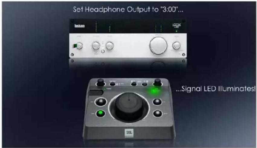
External A.I. Set Test Levels

External A.I. Set Test Levels, Step 1
On-Screen Instructions: "For this test ensure that connected audio sources and open audio applications are in 'STOP' mode and are not sending signals to the MSC1. Click (NEXT) to proceed."
Note: No audio sources external to the MSC1 Control Center should be playing during RMC™ Calibration. The MSC1 test signals will stop playing if you click on the desktop or an application other than MSC1 Control Center. Make sure the MSC1 Control Center is the active application during the entire RMC Calibration Procedure.
Before initiating an RMC Calibration, it is important no other audio or sound files are being played through your computer or the MSC1. You do not have to close all audio applications, but playback of all files should be stopped. Make sure that the listening environment is quiet, and noise in the room produced by equipment, traffic and people is kept to a minimum. This includes noise from appliances, fans, air conditioning, and talking. All of these sounds will be picked up by the RMC microphone, potentially compromising RMC results.
The MSC1 Control Center Audio is active only when Control Center is the currently selected application. Clicking on the desk top or another window, while a test signal is playing will shift the focus away from the Control Center, stop the audio and interrupt the procedure. To restore the operating functionality, click within the MSC1CC Window. Make sure the MSC1 Control Center remains the active application throughout the RMC Calibration Procedure.

External A.I. Set Test Levels, Step 2
On-Screen Instructions: "Click (START) on the panel below to activate the Test Signal and Level Meter. Sound may not be audible. Click (NEXT) to proceed."
Note: Click (START), then Click (NEXT). The test signal can be started and stopped at any time during this test.
Clicking (START) begins the playback of a multi-tone wave file and at the same time activates a Level Meter that reports the input channel's current average level relative to 0dBFS. The meter allows you to see the audio level while making adjustments.

External A.I. Set Test Levels, Step 3
On-Screen Instructions: "Increase the setting of the Headphone Output on your Audio Interface to "3:00." The MSC1 Signal LED may illuminate. Click (NEXT) to proceed."
Note: For most audio interfaces, the 3:00 position will produce an output level 80% of maximum which is optimum for RMC^TM Calibration.
Note: If your audio interface does not have a dedicated Headphone Output Control adjust the setting of the audio interface Main Output Control instead.
Slowly increase the headphone output level control of your External Audio Interface to the 3:00 position. As the setting of the headphone output is increased, the MSC1 Signal Present light should become illuminated, but you should not hear any audio in the room. The Clip LED should not illuminate.

External A.I. Set Test Levels, Step 4
On-Screen Instructions: "Increase the Output Level Slider to 80%. Click (NEXT) to proceed."
Note: Arrow keys or a mouse jog wheel can be used to adjust the sliders in fine increments.
The 80% setting produces a sufficient volume level as the RMC process proceeds. You should still not hear sound from the speakers.

External A.I. Set Test Levels, Step 5
On-Screen Instructions: "Adjust the Mic/Line Input Gain Control on your Audio Interface until the Level Indicator displays a value of approximately -26 dB. The Level Meter should be Red. Click (NEXT) to proceed."
Note: Adjusting the Mic/Line Input Gain sets the system input sensitivity to optimize the audio path for the RMC™ measurements.
Adjustments made to the Mic/Line input gain optimize input sensitivity and noise floor of the RMC Calibration measurements. External sounds in the environment produced by air conditioners, and noisy equipment in your room may significantly affect the noise floor. We recommend turning off all non-essential noise producing devices to keep the noise floor as low as possible.

External A.I. Set Test Levels, Step 6
On-Screen Instructions: "Turn the MSC1 VOLUME to the "12:00" setting. The speakers should reproduce the test signal at a soft level. Click (NEXT) to proceed."
Note: With the volume control set to 12:00 the input gain structure is optimized for typical use.
As the MSC1 VOLUME control setting approaches "12:00" you should hear the multi-tone test file playing at a low level through the speakers.

External A.I. Set Test Levels, Step 7
On-Screen Instructions: "Listen to the system for any distortion. If you hear distortion or notice that the MSC1 Clip LED is illuminated, check all settings. Click (NEXT) to proceed."
Note: If the MSC1 CLIP LED is illuminated, reduce the setting or the Computer Audio Interface Headphone Output until the Clip LED is no-longer illuminated and distortion is not audible.
You should hear a multi-tone signal, comprised of several sine waves. Improper gain settings may cause clipping, an over-driving of the system resulting in audible distortion. The distortion is likely produced at the output of the Audio Interface. If you hear distortion, adjust the soundcard level controls one at a time, reducing the setting of each control until the source of the clipping and resulting distortion is eliminated.

External A.I. Set Test Levels, Step 8
On-Screen Instructions: "Adjust the MSC1 INPUT TRIM until the Level Meter turns Green and the Level Indicator displays a value between -20 dB and -9 dB or until the Volume becomes uncomfortably loud. Click (NEXT) to proceed."
Note: The multi-tone test signal will be heard through speakers connected to the “A” SPEAKER and SUB OUTPUTS. When the Level Meter displays a Green color, this indicates a valid level between -20 dB and -9 dB has been achieved. The volume should be perceived as slightly louder than a strong speaking level.
The multi-tone sound file you hear is comprised of multiple sine waves of equal amplitude at 40 Hz, 80 Hz, 160 Hz and 320 Hz. This test signal, will be heard from speakers connected to the "A" SPEAKER Outputs, at a level perceived to be louder than normal speech. The Level Meter will become Green in color indicating a valid level between -20 dB and -9 dB has been achieved. As increasing the setting of the MSC1 INPUT TRIM causes the on-screen Level Meter reading to increase. Ideally, RMC ^™ Calibration should be run with a level reading of approximately -9 dB. If the system volume becomes uncomfortably loud prior to achieving -9 dB, reduce the MSC1 INPUT TRIM setting to achieve a comfortable listening level. After doing this, the on-screen Level Meter may be Red in color.

External A.I. Set Test Levels, Step 9
On-Screen Instructions: "If the Volume is uncomfortably loud, Adjust the MSC1 INPUT TRIM to produce a comfortable Volume. If necessary, Adjust the Mic/Line Gain Control on your Audio Interface until the Level Meter is Green or until the Mic/Line Gain Control on your Audio Interface is at 100%. Click (NEXT) to proceed."
Note: If the Volume is comfortable and the Level Meter is Green, Click (NEXT). If the Volume is uncomfortably loud or if you think you are doing damage to your speakers at that level, turn the INPUT TRIM down to a safe level. Then Adjust the Mic/Line Input Gain until the Level Meter is Green.
If the Volume is comfortable and the Level Meter is Green, Click (NEXT). If the Volume is uncomfortably loud or if the speakers are producing distortion, reduce the setting of the MSC1 INPUT TRIM to an acceptable level. Then Adjust the Computer Audio Interface Mic/Line Input Gain until the on-screen Level Meter is Green in color. A maximum signal-to-noise ratio is needed for a valid RMC™ measurement. In noisy environments, the speakers must play louder to achieve a successful calibration. The greater the difference between the noise floor and the speaker output level, the better the conditions for RMC Calibration. To check this difference, you can silence the audio test signal by pressing the MUTE button on the MSC1 and reading the noise floor level from the on-screen Level Indicator located above the Level Meter. Then Press MUTE again, restoring the audio test signal, and read the Level Indicator to determine the speaker output level. Next subtract the Noise floor measurement from the Speaker Output level measurement. A difference of 22 db is optimum for successful calibration. Make sure the MUTE is disabled (the control is not illuminated) before continuing.

External A.I. Set Test Levels, Step 10
On-Screen Instructions: "If the Level Meter still displays a Red Level, Set the MSC1 RMC MIC LEVEL PAD to the In position. Adjust the Mic/Line Gain Control of the Audio Interface until a Green level is reached. Click (NEXT) to proceed."
Note: If the Volume is comfortable and the Level Meter is Green, Click (NEXT). If the audio interface Mic/Line Gain Control is at maximum and the Level Indicator still displays a reading less than -20 dB, use a paperclip or similar object to Set the MSC1 RMC MIC LEVEL PAD to the In position.
If the Volume is comfortable and the Level Meter is Green, Click (NEXT). If your Mic/Line Gain Control is at Maximum and your Level still displays below -20 dB, use a paperclip or similar object to set the MSC1 RMC MIC LEVEL PAD to the IN position. Insert the paper clip and press gently on the internal switch. You may Click (STOP) or press the MUTE control while doing this. This switch is located behind an aperture on the rear panel of the MSC1 just above the Headphone jack and is marked LEVEL PAD. Pushing this switch in adds 8 dB of gain to the mic signal, which should allow you to lower your Mic/Line Gain Control. Because the LEVEL PAD directly increases the noise floor of the measurement, it should not be engaged unless necessary. You may Click (STOP) or Press the MUTE control while doing this if a Green Level Meter is still can not be achieved, and your speakers producing distortion, RMC Calibration is not possible in this environment at this distance. The cause could be any of the following: The environment is noisy; the listening distance and therefore the microphone distance from the speakers is too great; the speakers in this system are not capable of adequate output. Please contact JBL Customer Service using the Technical Support page of this user's guide.

External A.I. Set Test Levels, Step 11
On-Screen Instructions: "Click (STOP) to stop the test signal, and then Click (NEXT) to proceed."
Note: Click (STOP) or (NEXT) to proceed. The MSC1 Control Center Software will save the current settings of the Input and Output Level Sliders. These settings will be used later in the RMC™ Calibration Procedure.
The Input Level Slider and Output Level Slider values are stored in software and recalled prior to RMC Calibration. Once RMC Calibration is complete, slider settings are stored as part of the RMC Test Settings so they can be reused any time you run the RMC Calibration, eliminating the need to repeat the preceding steps.
RMC™ Timeline Section 4: Loopback Test

Internal S.C. Loopback Test

Internal S.C. Loopback Test, Query
On-Screen Instructions: "It appears that the Loopback Test has already been run. Would you like to re-run the Loopback Test?"
Note: This test should be re-run if you are using a different computer or soundcard than previously used for RMC Calibration. If you are repeating RMC using the same audio path and soundcard, you can Click (NO) to skip the Loopback Test.
Once you have completed RMC, a number of settings and files are stored, including the frequency response of your Internal Soundcard. Once this test has been successfully completed, you do not have to repeat the test unless you change your computer or soundcard. If the MSC1CC finds no evidence of successful completion of the Loopback test, this step does not appear and you are presented with instructions for the Loopback Test Overview.

Internal S.C. Loopback Test, Overview
On-Screen Instructions: "Click (NEXT) to view Step-by-Step instructions for the connections shown above. Otherwise, make the connections shown and then Click (SKIP). Do not change any Volume settings during the process."
Note: The Loopback test consists of making a direct connection between your soundcard headphone output and the soundcard microphone input and then measuring the frequency response and gain of the soundcard audio path. The MSC1 and speakers are not measured during this test. Audio should NOT be audible during this test.
During the Loopback Section you are prompted to make a connection between the soundcard headphone output and its mic input. The test measures the frequency response, input-to-output gain, and linearity of your soundcard. The MSC1 and speakers are not measured during this test; it is solely a test of the soundcard internal electronics. This measurement ensures that variables, potentially introduced by the soundcard are eliminated and do not influence the measurement of the speakers. This Loopback test data is stored allowing you to skip the Loopback test when RMC ^™ Calibration is repeated, using the same hardware.
The supplied stereo 3.5mm (1/8 inch) to 3.5mm (1/8 inch) cable is all that is required to make the required connections. If your soundcard provides a larger 6.5mm (1/4 inch) input and/or headphone output, use the supplied adaptors.

Internal S.C. Loopback Test, Step 1
On-Screen Instructions: "Disconnect the Phono Cable's 3.5mm plug from your Soundcard Headphone jack. Do not disconnect the Phono plugs from the MSC1 "C" Inputs. Click (NEXT) to proceed."
Note: Leaving the Phono plugs connected makes the following steps easier.
Unplug the 3.5mm (1/8 inch) side of the cable from the internal soundcard headphone output. Leave the other end of the cable (the Phono plugs) connected to the MSC1 "C" Inputs.

Internal S.C. Loopback Test, Step 2
On-Screen Instructions: "Disconnect the 3.5mm Cable from the MSC1 RMC™ MIC OUT jack. Click (NEXT) to proceed."
Note: Disconnect the 3.5mm Cable from the MSC1 RMC MIC OUT jack and hold it in your hand. Click (NEXT) for the next instruction.
After disconnecting the 3.5mm Cable, keep the 3.5mm plug of the cable in your hand because it will be utilized in the following instruction.

Internal S.C. Loopback Test, Step 3
On-Screen Instructions: "Insert THIS 3.5mm Cable into your Soundcard Headphone jack. Use the supplied Adaptor if needed. Click (NEXT) to proceed."
Note: When this step is completed a cable will connect the soundcard headphone output and the soundcard Mic input, as shown in the illustration.

Internal S.C. Loopback Test, Running
On-Screen Instructions: "To begin the Loopback Test, Click (START). During this test, you should not hear audio. If you hear audio Click (STOP) and check your connections and settings. A successful Loopback test is required to run RMC Calibration."
Note: The loopback test is measuring the soundcard's internal electronics only and therefore generates no audible signal. The test takes between 10 seconds and 2 minutes to complete. You may notice that the Level Sliders move during the test. No user adjustments are required during this test.
The loopback test is measuring the soundcard's internal electronics only and therefore generates no audible signal. If any sounds are heard during this test, Click (STOP) and confirm all connections and settings were made according to directions in the previous steps. RMC Calibration can only be successfully performed after the Loopback data from this test is completed. If you experience problems completing this step please contact JBL Customer Service using the Technical Support page of this user's guide.

External A.I. Loopback Test

External A.I. Loopback Test, Query
On-Screen Instructions: "It appears that the Loopback Test has already been run. Would you like to re-run the Loopback Test?"
Note: This test should be re-run if you are using a different computer or Audio Interface than previously used for RMC™ Calibration. If you are repeating RMC using the same audio path and Audio Interface, you can Click (NO) to skip the Loopback Test.
Once you have completed RMC, a number of settings and files are stored, including the frequency response of your External Audio Interface. Once this test has been successfully completed, you do not have to repeat the test unless you change your computer or Audio Interface. If the MSC1CC finds no evidence of successful completion of the Loopback test, this step does not appear and you are presented with instructions for the Loopback Test, Overview.

External A.I. Loopback Test, Overview
On-Screen Instructions: "Click (NEXT) to view Step-by-Step instructions for the connections shown above. Otherwise, make the connections shown and then Click (SKIP). Do not change any Volume settings during the process."
Note: The Loopback test requires a direct connection between the External Audio Interface Headphone output and its Mic/Line Input. The test measures the frequency response and gain of the Audio Interface audio path. The MSC1 and speakers are not measured during this test. Audio should NOT be audible during this test.
During the Loopback Section you are prompted to connect your Audio Interface Headphone output directly to its Mic/Line Input. This test measures the frequency response, input-to-output gain, and linearity of your Audio Interface. The MSC1 and speakers are not measured during this test; it is solely an internal electronics test for the External Audio Interface. No audio should be heard during this test. This measurement ensures that variables, potentially introduced by the soundcard are eliminated and do not influence the measurement of the speakers. This Loopback test data is stored and can be used again allowing you to skip the Loopback test when RMC Calibration is repeated using the same hardware.
The supplied stereo 3.5mm (1/8 inch) to 3.5mm (1/8 inch) cable is all that is needed to make the required connections. If your Audio Interface provides a larger 6.5mm (1/4 inch) input and/or headphone output, use the supplied adaptors.

External A.I. Loopback Test, Step 1
On-Screen Instructions: "Disconnect the Phono Cable's 3.5mm plug from your Audio Interface Headphone jack. Do not disconnect the Phono plugs from the MSC1 "C" Inputs. Click (NEXT) to proceed."
Note: Leaving the Phono plugs connected makes the following steps easier.
Disconnect the 3.5mm (1/8 inch) plug from the Audio Interface headphone output. Leave the other end of the cable with the Phono plugs, connected to the MSC1 "C" Inputs.

External A.I. Loopback Test, Step 2
On-Screen Instructions: "Disconnect the 3.5mm Cable from the MSC1 RMC™ MIC OUT jack. Click (NEXT) to proceed."
Note: Disconnect the 3.5mm Cable from the MSC1 RMC MIC OUT jack and hold the plug in your hand.
This plug will be connected elsewhere momentarily.

External A.I. Loopback Test, Step 3
On-Screen Instructions: "Insert THIS 3.5mm Cable into your Audio Interface Headphone jack. Use the supplied Adaptors if needed. Click (NEXT) to proceed."
Note: When this step is complete, the cable will connect the Audio Interface headphone output to the Audio Interface Mic/Line Input, as shown in the illustration.

External A.I. Loopback Test, Running
On-Screen Instructions: "To begin the Loopback Test, Click (START). During this test, you should not hear audio. If you hear audio, Click (STOP) and check your connections and settings. A successful Loopback test is required to run RMC Calibration."
Note: The loopback test is measuring the External Audio Interface's internal electronics only and therefore generates no audible signal. The test takes between 10 seconds and 2 minutes to complete. You may notice that the Level Sliders move during the test. No user adjustments are required during this test.
If any sounds are heard during this test, Click (STOP) and confirm all connections and settings were made according to directions in the previous steps. RMC Calibration can only be successfully performed after the Loopback data from this test is completed. If you experience problems completing this step please contact JBL Customer Service using the Technical Support page of this user's guide.
RMC™ Timeline Section 5: Audio Reconnect
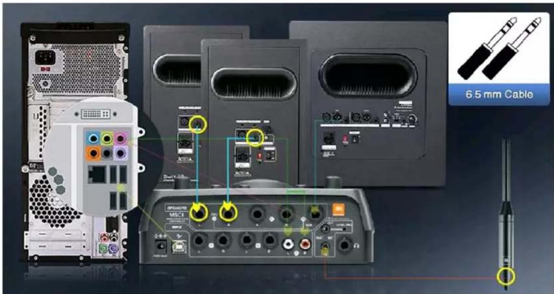
Internal S.C. Audio Reconnect

Internal S.C. Audio Reconnect Overview
On-Screen Instructions: "Click (NEXT) to view Step-by-Step instructions to restore the connections shown above. Otherwise, restore the connections shown and then Click (START) to verify your levels. Once verified, Click (SKIP)."
Note: Reconnect your system to play audio. Check the Level Meter to confirm connections have been made properly and level settings have not changed.
Now that the loopback test has confirmed your computer and its internal soundcard are correctly configured, the system connections should be restored. This is accomplished by reconnecting the MSC1 Input “C” jacks to the soundcard headphone output using the Phono cable, and connecting the MSC1 rear panel RMC MIC OUT jack to the soundcard mic input using the 3.5mm cable. Click (NEXT) to view detailed instructions for restoring of these connections. Click (START) to play the audio test signal and using the MSC1CC Level Meter, confirm the level settings haven’t changed. The Level Meter should be Green in color and the Level Indicator should display the same value as in Section 3,” Internal S.C., Set Test Levels.” Click (STOP) once this is confirmed. If the level is different, review all connections and levels, make the necessary changes and perform this step again. If necessary, repeat Section 2 Internal S.C. Connections and Section 3 Internal S.C. Set Test Levels.

Internal S.C. Audio Reconnect, Step 1
On-Screen Instructions: "Disconnect the 3.5mm Cable from your Soundcard Headphone jack and re-connect it to the MSC1 RMC™ MIC OUT jack. Click (NEXT) to proceed."
Note: The MSC1 rear panel RMC MIC OUT should be connected to the soundcard Mic Input using the 3.5mm cable (3.5mm to 3.5mm.)
If the soundcard has a 6.5mm (1/4 inch) mic input, use the female balanced 3.5mm (1/8 inch) to male balanced 6.5mm (1/4 inch) adaptor. This is the same connection as previously made in Internal S.C. Connections, Step 4.

Internal S.C. Audio Reconnect, Step 2
On-Screen Instructions: "Re-connect the Phono Cable's 3.5mm plug to your Soundcard Headphone jack using the supplied Adaptor if necessary. Click (NEXT) to proceed."
Note: The soundcard headphone output should be connected to the MSC1 Inputs "C" using the supplied Phono cable.
This is the same connection as previously made in Internal S.C. Connections, Step 1.

Internal S.C. Audio Reconnect, Step 3
On-Screen Instructions: “Click (START) to confirm the Level Meter is Green and the Level Indicator is between -20 dB and -9 dB. Otherwise, review all of your connections and settings as required. Click (STOP) when confirmation is complete. Click (NEXT) to proceed.”
Note: You'll notice the Level Meter and Level Indicator indicate the level of audio heard in the room, and displays levels and numbers similar to those in Section 3, "Internal S.C. Set Test Levels."
Click (START) to play the audio test signal and using the MSC1CC Level Meter, confirm the level settings haven't changed. The Level Meter should be Green and the Level Indicator should display the same value as in Section 3, "Internal S.C., Set Test Levels." Click (STOP) once this is confirmed. If the level is different, review all connections and levels, make the necessary changes and perform this step again. If necessary, repeat Sections 2 Internal S.C. Connections and Section 3 Internal S.C. Set Test Levels.

External A.I. Audio Reconnect

External A.I. Audio Reconnect, Overview
On-Screen Instructions: "Click (NEXT) to view Step-by-Step instructions to restore the connections shown above. Otherwise, restore the connections shown and then Click (START) to verify your levels. Once verified, Click (SKIP)."
Note: Reconnect your system to play audio, Check the Level Meter to confirm connections have been made properly and level settings have not changed.
Now that the Loopback Test has confirmed your computer and External Audio Interface are correctly configured, the system connections should be restored. This is accomplished by reconnecting the MSC1 Input “C” jacks to the Audio Interface headphone output using the Phono cable, and connecting the MSC1 rear panel RMC™ MIC OUT jack to the Audio Interface mic input using the 3.5mm cable. Click (NEXT) to view detailed instructions for restoring these connections. Click (START) to play the audio test signal and using the MSC1CC Level Meter, confirm the level settings haven’t changed. The Level Meter should be Green in color and the Level Indicator should display the same value as in Section 3,” External A.I., Set Test Levels.” Click (STOP) once this is confirmed. If the level is different, review all connections and levels, make the necessary changes and perform this step again. If necessary, repeat Section 2, External A.I. Connections and Section 3, External A.I. Set Test Levels.
EXTERNAL A.I.
External A.I. Audio Reconnect, Step 1
On-Screen Instructions: "Disconnect the 3.5mm Cable from your External Audio Interface Headphone jack and re-connect it to the MSC1 RMC™ MIC OUT jack. Click (NEXT) to proceed."
Note: The MSC1 rear panel RMC MIC OUT should be connected to the Computer Audio Interface Mic/Line Input using the 3.5mm Cable (3.5mm to 3.5mm).
If the Audio Interface has a 6.5mm (1/4 inch) mic input, use the female balanced 3.5mm (1/8 inch) to male balanced 6.5mm (1/4 inch) adaptor. This is the same connection as previously made in External A.I. Connections, Step 6.
EXTERNAL A.I.
External A.I. Audio Reconnect, Step 2
On-Screen Instructions: "Re-connect the Phono Cable's 3.5mm plug to your External Audio Interface Headphone jack using the supplied Adaptor if necessary. Click (NEXT) to proceed."
Note: The headphone output of the External Audio Interface should now be connected to MSC1 Inputs "C" using the supplied Phono cable.
This is the same connection as previously made in External A.I. Connections, Step 1.
EXTERNAL A.I.
External A.I. Audio Reconnect, Step 3
On-Screen Instructions: “Click (START) to confirm the Level Meter is Green and the Level Indicator is between -20 dB and -8 dB. Otherwise, review all of your connections and settings as required. Click (STOP) when confirmation is complete. Click (NEXT) to proceed.”
Note: You'll notice the Level Meter and Level Indicator indicates the audio heard in the room, and displays levels and numbers similar to those in Section 3, External A.I. Set Test Levels.
Click (START) to play the audio test signal and using the MSC1CC Level Meter, confirm the level settings haven't changed. The Level Meter should be Green in color and the Level Indicator should display the same value as in Section 3," External A.I. Set Test Levels." Click (STOP) once this is confirmed. If the level is different, review all connections and levels, make the necessary changes and perform this step again. If necessary, repeat Section 2 External A.I. Connections and Section 3 External A.I. Set Test Levels.
The instructions for the remaining two sections pertain to systems using either an External Audio Interface or an Internal Soundcard.
RMC™ Timeline Section 6: Speaker Configuration

natural_image
Three modern audio speakers on a dark background, no text or symbols visibleSpeaker Configuration Selection


Internal S.C. and External A.I. Speaker Configuration <6.0 Speaker Configuration>
On-Screen Instructions: "Please select the speaker configuration from the Drop-Down Menu below that applies to you. Once selected, Click (NEXT) to proceed."
Note: Prior to running RMC Calibration, use the Drop-Down Menu to let the system know your speaker configuration. This specifies the speakers to be measured during RMC Calibration. Note: If the selected Speaker Configuration includes a speaker that isn't present in the system, RMC Calibration will fail.
This Drop-Down Menu tells RMC which speakers to calibrate. Choose the configuration that matches the speaker set up connected to the “A” SPEAKER OUTPUTS of the MSC1. A subset of your speakers can be selected if you wish. For instance, if you have connected a Left Speaker, Right Speaker, and Subwoofer to the MSC1 “A” SPEAKER OUTPUTS, you can choose to calibrate just the Left and Right Speakers excluding the Subwoofer. RMC Calibration will fail if you include a speaker in your selected Speaker Configuration that isn’t there. The Software will attempt to measure Audio Level for a non-existent speaker. This will cause Control Center to display an error indicating insufficient level was detected.
Confirming your speaker configuration is always necessary prior to RMC Calibration, even when repeating RMC Calibration.
RMC™ Timeline Section 7: RMC Calibration

RMC Calibration is about to begin
In the final section the speakers are calibrated, results are compiled, and corrective filter settings are loaded into the MSC1.


Internal S.C. and External A.I. RMC Calibration, Mic Placement
On-Screen Instructions: "Position the Microphone at ear height in the listening position. Confirm the path between the speakers and the microphone is clear of people and objects. Click (START) to begin a 5 second countdown. Use this time to move away from your speakers and microphone. (For Example: Stand against the wall opposite your speakers.)"
Note: RMC Calibration is about to begin. The test can be stopped at any time by Clicking (STOP) and the test can be restarted at any time by Clicking (START).
The Control Center is ready to perform the RMC Calibration. It is important the supplied omni-directional microphone is placed in front of your speakers, at ear level, in your exact listening position prior to beginning Calibration. Be sure the path between the microphone and the speakers is clear of people and unnecessary objects. Open doors and windows change the acoustic character of the room, so prior to starting RMC Calibration, make sure you have opened or closed doors and windows to simulate typical conditions in the room. When you are ready, click the on-screen (START) button. This will begin a 5 second countdown, during which you should distance yourself from the speakers and microphone and position yourself in a location that doesn't interfere with the measurement; preferably in a spot near the wall opposite the speakers. The RMC Calibration process will begin at the conclusion of the countdown.


Internal S.C. and External A.I. RMC™ Calibration, Measurement
On-Screen Instructions: "RMC Calibration is Running. Please wait quietly. To discontinue RMC Calibration Click (STOP)."
Note: RMC Calibration is Running. Please wait quietly. To discontinue RMC Calibration Click (STOP).
Normally, when a subwoofer is used, a cross-over is applied that filters the low frequency content sent to the left and right speakers. However, during RMC Calibration, all speakers connected to the MSC1 “A” SPEAKER OUTPUTS, are played and measured as full-range speakers, even if a subwoofer is part of the system. This allows the Control Center to identify the room resonance for each speaker, making it possible to listen with, or without a sub at any time, (using the Sub ON/OFF control) without having to recalibrate the system. Talking and other noises should be kept to a minimum while the speakers are reproducing the test signal. Loud noises during the RMC process may lead to faulty test results. At any time, if you need to stop RMC Calibration you can Click (STOP) during the test. This allows you to re-start the test without loosing any settings or data collected up to that point. Clicking the (CANCEL) button will end Calibration and return you to the RMC Menu without altering the RMC settings in the MSC1. New RMC settings are sent to the MSC1 only after successful completion of the RMC Calibration process.
RMC Results
Once the RMC Calibration process has finished, a pop-up message will signal the completion status of the procedure.
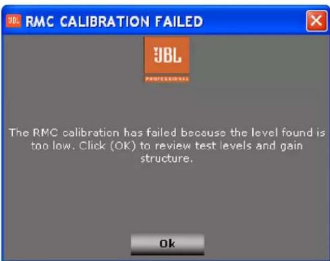
RMC Calibration Failure Message
If RMC ^™ fails to complete successfully, an error message with an explanation is displayed. In this case you will be directed to review pre-calibration procedures to diagnose and fix the problem. The RMC error codes are explained in the Troubleshooting section of this document.

RMC Complete Message
When RMC is successfully completed, a pop-up message displays the number of corrective filters applied. Next, the RMC Graph window (similar to the one below) displays the parametric information for the corrective filters applied during RMC Calibration.
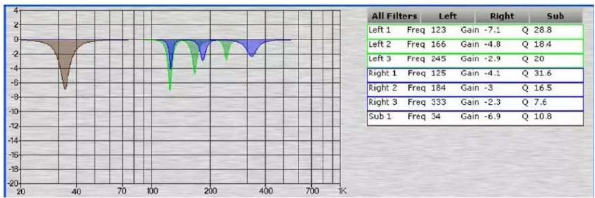
line
| Filter | Freq | Gain | Q | |---|---|---|---| | Left 1 | 123 | -7.1 | 28.8 | | Left 2 | 166 | -4.8 | 18.4 | | Left 3 | 245 | -2.9 | 20 | | Right 1 | 125 | -4.1 | 31.6 | | Right 2 | 184 | -3 | 16.5 | | Right 3 | 333 | -2.3 | 7.6 | | Sub 1 | 34 | -6.9 | 10.8 |RMC Results Graph
The filter for each speaker is color-coded; Green for the Left channel, blue for the Right, and brown for the Subwoofer. The parametric data is listed in the area adjacent to the graph. The buttons above this parametric data allow the viewing of the Left channel, Right channel, and/or Subwoofer filters individually or simultaneously. Note that the corrective filters displayed depend on the status of settings related to the subwoofer, including subwoofer crossover frequency, and whether the sub is currently ON or OFF. If the subwoofer is off, filters are applied to the Left and Right full range speakers to tackle room related problems found when the speakers are used full-range. If the subwoofer is on, filters are applied to the subwoofer to tackle resonance below the crossover frequency and filters are also applied to the Left and Right speakers to tackle resonance above the crossover frequency.
Once The RMC ^™ test is successfully completed, Room Mode Correction filters can be enabled or disabled The RMC control on the front panel of the MSC1 and also in the Control Center Software, allows you to easily audition your speakers with or without Room Mode Correction. Room Mode Correction is enabled when the RMC Control is illuminated. Pressing the RMC button incurs a 0.5 second pause in audio while filter data is loaded.
The current settings for the RMC Calibration remain in the MSC1 even after turning the unit off, and disconnecting the power supply from the unit. Upon Power up with the RMC control illuminated, RMC Calibration settings are applied to the audio path.
RMC Alignment
The RMC Alignment Menu in the MSC1 Control Center gives you access to special controls you can use to fine-tune performance of your system. In the ideal set up, all speakers are equidistant from the listening position. In cases where the ideal placement is not possible, these alignment level and delay controls can be used to compensate for differences in physical placement. Reducing the level and applying time delay to a speaker that is positioned closer to the listening position than the other speakers produces a more accurate stereo image. Although the RMC process balances all speakers within a 14 dB of each other, the user-adjustable level control for each speaker lets you introduce level “offsets” and balance speakers to taste. Additionally when used, the delay controls can restore the strongest possible stereo image and “phantom center” in cases where speakers are not exactly the same distance from the listening position. Additionally, this menu provides a duplicate of the subwoofer level and polarity controls found in the Top Screen of the MSC1 Control Center Software.
From the MSC1CC Top Screen, click the (RMC Menu) tab to enter the RMC Menu and then Click on (RMC Alignment.)

RMC Alignment Menu
The RMC ^™ Alignment Menu allows control of the “A” SPEAKER OUTPUT levels 42, time delay 43, and polarity 44 of a connected subwoofer. Modifications are made by moving the level sliders adjacent to each speaker. Note that whenever any of the RMC alignment parameters are changed using the software, the RMC control on the MSC1 front panel flashes to indicate new settings have been received. Changes are displayed in the software and heard in real-time.
For the Left and Right “A” speakers, Level and Time Delay controls are provided. The Level sliders apply up to 12dB of attenuation to each speaker (in 0.25dB increments). The Time Delay slider values are expressed in units of distance, over a range of 1 inch to 3 ft. 9 inches (in 1 inch increments). Applying delay to a speaker affects the way it sounds relative to another speaker when the same signal is present in both speakers. When a stereo mix is created, some signals are positioned in both the left and right speakers. In a properly aligned system, the same signal placed in both speakers is perceived to originate from a spot halfway between the two speakers. This spot is referred to as the “phantom center” because the signal sounds as if it is coming from a third speaker positioned halfway between the left and right speakers. When the left and right speakers can not be optimally positioned to produce a strong phantom center, and one speaker is further away out of necessity, the application of delay to the closer of the two speakers can restore the phantom center. Additionally, speakers can be delayed relative to the subwoofer or vice versa to ensure signals in common to the speakers and the subwoofer, are optimally reproduced. As mentioned, delay values are expressed in units of distance. For example, if the left speaker is 1 foot closer to the listening position than the right speaker, applying a value of 1ft. of time delay to the Left speaker will cause you to perceive its’ audio as if it originates 1 foot farther away, and the same distance from the listening position as the Right speaker. The correct delay value can be determined by measuring the distance from the listening position to each speaker. Delay should be applied to the closest speaker. A subjective evaluation of the delay setting should be done from the position that will be used for critical listening; in a production studio, the mix position.
The Subwoofer has 3 sliders; the Sub Level, with a range of ±10 dB (in 0.25 dB increments), Sub Time Delay, operating from 1 inch to 3 ft. 2 inches (in 1 inch increments), and Polarity, which is either 0 Degrees or 180 Degrees.

RMC Arrow Indicating Recommended Value
When RMC ^™ Calibration is performed, the RMC system automatically sets the levels of the Left, Right speakers and the Subwoofer for a balanced system. The recommended level value for each speaker is indicated by an arrow symbol pointing to the numeric level value. At any time, alignment parameters can be adjusted. Time Delay settings and Subwoofer Polarity are not calculated as part of the RMC Calibration process, and are set manually.
The RMC Alignment menu has additional controls that can be used to restore RMC settings.
Clicking (REVERT) 46 returns all of the Speaker Levels to the values calculated during RMC Calibration, and sets all Speaker Delays to 0 ft.
Clicking (REFRESH) 47 loads all of the current parameters from RMC Calibration (Filters and Level Settings) into the MSC1.
The following ACTIVITY 45 controls allow you to set preferences for the application of time delay values and level offsets.
The Always Enable option ensures Delay and Level settings will always be applied, independent of RMC filters and the status of the RMC Control.
When the Enable with RMC option is selected, delay and level offsets are applied only when the RMC CONTROL is illuminated and RMC filters are applied.
When the Never Enable option is selected, time delay and level offsets are always bypassed, regardless of the setting of the RMC Control.
The Text color of the alignment parameters is shown in black when the alignment data is not active and light gray when alignment is active.
RMC ^™ Troubleshooting Guide and Error code references:
Software will not launch
- Confirm that your computer meets the minimum system requirements listed on page 3 in this manual.
- Confirm that the software named MSC1 Control Center has been successfully installed to your computer's hard drive.
- Confirm that the MSC1 is connected to your computer with the supplied USB cable and that it is powered on.
- Use your computer's diagnostic tools to confirm that the USB port that the MSC1 is connected to is active and that there are no system conflicts.
I can not hear any audio from my speakers
- Confirm that your audio source is connected to the MSC1 and you have that input selected from the INPUT SELECT switches 1 and 2.
- Ensure that your audio source is playing and the Green SIGNAL LED is illuminated.
- Confirm your speakers are connected to the set of outputs you have selected using the SPEAKER SELECT switch and the speakers are powered on.
- Check that the MSC1 Volume control is not set to - .
• Make sure the MUTE control on the MSC1 is not enabled (not illuminated).
I can not hear any audio from my headphones
- Confirm your audio source is connected to the MSC1 inputs and the corresponding INPUT SELECT switch 1 or 2 is selected.
- Ensure your audio source is playing and the Green SIGNAL LED is illuminated.
- Check that your headphones are connected to the Headphone output of the MSC1 HEADPHONE OUTPUT as specified in the MSC1 Owner's Manual.
- Check that the HEADPHONE VOLUME control is not set to the full counterclockwise position.
• Make sure the MUTE control on the MSC1 is not enabled (not illuminated).
My headphones sound distorted or are very loud
- Reduce the setting of the HEADPHONE VOLUME control to a comfortable level.
- If you are listening at low levels and the audio is still distorted, the external audio source itself may be producing the distortion. Reduce the volume of the audio source using available level controls in the external equipment.
• Always use caution when setting the headphone volume to avoid levels that can damage your hearing or the headphones.
Audio output is very low
- Confirm -10 dBV equipment is not connected to the "A/B" inputs. Check the MSC1 Owner's Manual connection guidelines for balanced and unbalanced signals.
- Confirm your audio source is connected to the MSC1, sending a strong signal and is connected to the selected input connectors. Refer to the MSC1 Owner's Manual recommendations for use of balanced and unbalanced connections.
- Check that the MSC1 Volume control is not set to - .
- Increase the setting of the MSC1 INPUT TRIM control.
- Increase setting of level controls on speakers or power amplifier.
- If your speakers are connected using unbalanced connections, use balanced connections. Refer to the MSC1 Owner's Manual and documentation for connected speakers.
Audio sounds distorted
- Confirm +4 dBu equipment is not connected to the "C" inputs. Check the MSC1 Owner's Manual connection guidelines for balanced and unbalanced signals.
- If the Red CLIP LED is illuminated, reduce the setting of the INPUT TRIM control until the LED is no longer illuminated.
- Check that the input sensitivity controls on your speakers are set to accept high level signals. The MSC1 is capable of producing professional level output of up to +17dBu which may clip the input of speakers. If the speaker does not have an input sensitivity control, we recommend increasing the setting of the speaker volume control. This will allow you to reduce the level sent to the speaker from the MSC1.
- Make sure you are not driving your loudspeakers beyond rated SPL output capability, as this can cause damage to your speakers.
No difference in sound when the EQ control is pressed in or out
- Confirm that the MSC1 SPEAKER SELECT switch is set to "A". EQ affects only signal sent to the "A" SPEAKER OUTPUTS.
- Click on the "EQ Graph" tab and confirm an EQ curve has been set and EQ Gain not set to 0dB for both the Low Frequency and High Frequency filters).
No difference in sound when the SUB control is pressed in or out
- Confirm that a subwoofer is connected to the MSC1 "A" Sub SPEAKER OUTPUT.
- Confirm that the MSC1 SPEAKER SELECT switch is set to "A". The Subwoofer is not available when monitoring using the "B" SPEAKER OUTPUTS.
• Make sure that there is a low frequency component to the signal being monitored.
My system does not seem to make any bass
- Confirm that a subwoofer is connected to the MSC1 Sub Output.
- Confirm that the MSC1 SPEAKER SELECT switch is set to "A". The Subwoofer is not available when monitoring using the "B" SPEAKER OUTPUTS.
• Make sure that there is a low frequency component to the signal being monitored. -
If your system does not include a subwoofer, make sure the SUB control is not enabled (not Illuminated).
-
Even if the subwoofer includes outputs for connection to the left and right main speakers, confirm speakers are connected directly to the "A" Left and Right outputs of the MSC1, not to the subwoofer. Connect the subwoofer directly to the SUB output of the MSC1. Set crossover frequency controls on the subwoofer to the highest available frequency setting. If the subwoofer includes an LFE (Low Frequency Effects) Input, connect the MSC1 to this input.
- Refer to the MSC1 Owner's Manual and your speaker equipment manuals for proper cables and connection guidelines.
I hear high frequency noise from my speakers whenever the MSC1 is connected to my computer via USB
- If you are connecting the MSC1 through a USB Hub, with other USB devices also connected to the USB Hub, try connecting the MSC1 directly to a single USB port on your computer. This will isolate the MSC1's USB connection and may eliminate the noise. Alternately, try connecting each of the other USB devices directly to a single USB port on your computer.
- If the MSC1 is not connected to a USB hub and other devices are connected to your computer using individual USB ports, try removing these other devices one-by-one to identify the one that is creating the high frequency noise. If you discover one particular device is causing the interference, avoid connecting the device to your computer while the MSC1 USB connection is being used.
The RMC™, EQ, and SUB controls in the Virtual MSC1 do not light when pressed
- The MSC1 SPEAKER SELECT switch is set to "B". Processed signal (RMC and/or EQ) and subwoofer signal is heard only when monitoring the "A" SPEAKER OUTPUTS. Only flat, unprocessed signal is routed to "B" SPEAKER OUTPUTS.
- Check USB connection to the MSC1 Control Center Software and make sure the MSC1 is powered on and linked. Disconnect and reconnect the USB cable to re-link Control Center Software with MSC1.
When I press the RMC, EQ, and/or SUB controls on the MSC1, they flash three times and do not change state
- Verify the MSC1 SPEAKER SELECT switch is set to "A." The RMC, EQ, and SUB controls are inactive when the "B" Speakers are selected.
- If after retrying the controls they still flash three times without changing state and you are connected to a computer via USB, disconnect the USB cable, wait 10 seconds, then reconnect the USB Cable and try the front panel controls again once the MSC1 has finished linking with the Control Center.
- If the above does not remedy the problem, power the MSC1 off, disconnect the power cable, wait 20 seconds, reconnect the power cable. After the device has linked to the Control Center, try using the controls again.
None of the onscreen tabs except "MSC1 Options" are functional
• The MSC1 SPEAKER SELECT switch is set to "B".
- Check USB connection to the MSC1 Control Center Software and make sure the MSC1 is powered on and linked.
No difference in sound when the RMC ^TM control is pressed in or out
- Confirm that the MSC1 SPEAKER SELECT switch is set to "A". RMC affects only signal sent to the "A" SPEAKER OUTPUTS.
- Click on the RMC Graph tab and confirm that there is valid RMC data. The multicolored table in the upper right hand corner displays a list of RMC filters placed during RMC Calibration. This table will be blank if RMC Calibration has not been performed or if RMC did not identify acoustic problems requiring filters.
Help tips are continually shown onscreen
- Click on the “MSC1 Options” tab and uncheck “Select to show help tips when mousing over a control.”
Automatic Firmware Update fails (FIRMWARE UPDATE SUCCESSFUL message is not displayed)
- Close all applications running on your computer except for MSC1 Control Center Software.
- Remember to perform all firmware update procedures with the SPEAKER SELECT switch in the "A" position.
- If this is your first time performing a firmware update, before attempting a manual update or automatic update, make sure to perform all of the configuration procedures in the “Updating MSC1 Firmware” section (pages 91-96) of this manual.
- Exit the MSC1 Control Center Software, unplug the USB cable connecting the computer to the MSC1, power down the MSC1, and then wait 30 seconds. Re-power the MSC1, and turn the EQ feature on. Then launch the MSC1CC and attempt the automatic firmware update again.
- If the MSC1 does not link to the Control Center Software perform a manual firmware update.
If the above measures do not correct the problem, please contact JBL Customer Service using the Technical Support page of this user's guide.
RMC™ Calibration error troubleshooting guide
MSC1 FAQ:
Q: I am using an External Audio Interface and the audio I hear is not distorted. As soon as I launch the MSC1 CC Software, the audio becomes distorted and the pitch of the audio seems to change.
A: Some Audio Interfaces reference the same computer audio settings information as MSC1 Control Center Software. We recommend launching the MSC1 CC Software prior to launching any other audio applications.
Q: The MSC1 CC Software looses connection to the MSC1 if another USB device is disconnected.
A: To recover the USB connection, close and re-launch the MSC1 CC Software.
Q: The MSC1 is producing audio, but the controls no longer respond.
A1: If USB is connected, disconnect USB and verify MSC1 controls have recovered. Then reconnect the USB cable.
A2: If disconnecting USB does not resolve the problem, remove the power cable from the MSC1 and wait 10 seconds. Reconnect the power cable and wait for the power LED to flash twice. Then press the POWER button.
Q: My computer boots slower with the MSC1 USB connection plugged in.
A: Your computer looks at any USB device connected as a possible boot source which may slow down your boot-up sequence. For faster boot times, disconnect the MSC1 USB connection until you are logged in and your system has completed the start up process.
RMC Troubleshooting FAQ:
RMC Timeline Section: COMPUTER SETTINGS:
Q: I am selecting my audio drivers using the Drop-Down Menu, but my audio originates from a different soundcard than the one selected.
A1: Your computer operating system has a different default soundcard selected. You will need to change your computer soundcard selection. From the START menu, go to the Control Panel and locate and click "Sounds" or "Sound and Audio Devices". Click on the Audio tab at the top and then select the appropriate soundcard or Audio Interface from the Drop-Down Menus. Once the soundcard you wish to use is selected in these menus, click "Apply" at the bottom and close the panel. Return to the Control Center RMC procedure and select the appropriate soundcard using the Drop-Down Menu.
A2: If you have an External Audio Interface connected to your system, but you are trying to run RMC using your internal soundcard, this can be the cause. In this case, you should disconnect your External Audio Interface from your system until RMC is complete. Once the External Audio Interface is disconnected, you should be able to select the appropriate audio drivers in the Control Center Drop-Down Menu.
Q: I am using an External Audio Interface and I see a message asking me to select an Audio Input Channel but the menu is blank. Why isn't there an option available? What should I do?
A: You are trying to use an External Audio Interface, but your computer operating system still thinks you are trying to use your internal soundcard. You will need to change your computer soundcard selection. From the START menu, go to the Control Panel, locate and click "Sounds" or "Sound and Audio Devices". Click the "Audio" tab at the top and then select the appropriate soundcard from the Drop-Down Menus. Once the soundcard you wish to use is selected in these menus, click "Apply" at the bottom and close the panel. Return to the Control Center RMC™ procedure and select the appropriate soundcard using the Drop-Down Menu.
Q: Which Audio Input Channel do I select from the Drop-Down Menu?
A: This selection connects the software audio path to your hardware microphone input. The easiest way to find the correct selection is to open a recording application such as Sound Recorder which can be located by navigating to and clicking on Start Menu\Programs\Accessories\Entertainment\Sound Recorder. Under the Edit menu, select Audio Properties, then click the "Volume..." button under the Sound recording area. This opens the Recording control and should list all of your Audio Input Channel options. With the MSC1 RMC Calibration Microphone connected to the MSC1 Mic IN jack, and the MSC1 Mic OUT jack connected to the soundcard input, move all of the volume controls to maximum. Press Record in the Sound Recording application and talk into the microphone; then use the select boxes across the bottom of the Recording control to select different input channels until you see a waveform move with your voice. You can ignore inputs named CD Player or Mixer, and for most soundcards, the Audio Input Channel contains the word Mic or Microphone in the name. Once you confirm the correct channel name for the hardware jack, you can close the other windows and applications and return to the RMC procedure.
RMC Timeline Section: CONNECTIONS:
Q: Why do I have to connect the RMC Microphone to the MSC1, rather than connect it directly to my computer microphone input?
A: The RMC Microphone requires power and amplification provided by the MSC1. The MSC1 MIC OUT is also conditioned to optimize the mic signal for RMC Calibration. Since computer microphone inputs differ, the MSC1 allows interface of the RMC Calibration Microphone with any computer sound card or External Audio Interface.
Q: If I do not have a subwoofer connected, why do I have to have the SUB Control enabled?
A: Calibrating audio test levels with the subwoofer enabled makes the procedure consistent for all users with and without subwoofers. RMC measurements are made full range without any crossover filters applied, to optimize the system with and without subwoofer crossovers enabled.
RMC™ Timeline Section: SET TEST LEVELS
Q: Audio disappears when I click on an element outside of the MSC1 Control Center Software during any part of the RMC Calibration Procedure.
A: The MSC1 CC Software will only send or receive audio through your system when it is the selected application. In any test during RMC the MSC1CC software must be the active application for the test signals to be set and for the Level Meters and data collection to work.
Q: During the Set Test Levels step the Level Meter does not change or move, regardless of the setting of the Input Level Slider.
A1: No audio or very low signal level is being detected by the application. Review all of your microphone connections and settings. Refer to the question above “Which Audio Input Channel do I select from the Drop-Down Menu?” and verify you have the correct Audio Input Channel selected.
Q: I hear the microphone through my speakers.
A: Your Microphone playback channel is not muted, and it should be for RMC. Open your computer Volume Control by navigating to and clicking Start\Control Panel\Sounds or Sound Devices. Click the Audio tab at the top, and then click on "Volume..." in the Sound playback section. Find the channel with the name that matches your selected Audio Input Channel and make sure the Mute check box for that channel is checked.
Q: I hear feedback or high levels of noise through my speakers?
A: Your Microphone playback channel is not muted, and it should be for RMC. Open your computer Volume Control by navigating to and clicking Start\Control Panel\Sounds or Sound Devices, and opening these options. Click on the Audio tab at the top, and then click on "Volume..." in the Sound playback section. Find the channel with the name that matches your selected Audio Input Channel and make sure the Mute check box for that channel is checked.
Q: My Input Volume Slider is turned up to 100% and I still can not get the Level Meter to read close to -30 dB? What do I do?
A1: If your input levels are too low, the first thing to try is using the MIC PAD switch on the rear of the MSC1. Use a paperclip or something similar to push this switch to the IN position. This increases the gain of the microphone circuit. Once the switch is engaged, repeat the test. If you still need more gain, continue to A2.
A2: In some systems it may be necessary to increase the gain of the input channel. In this case, open your Recording Controls by navigating to and clicking Start\Control Panel\ Sounds or Sound Devices, and open these options. Click the Audio tab at the top, and then click on "Volume..." in the Sound recording section. Find the channel with the name that matches your selected Audio Input Channel and click on the "Advanced" button for that channel. You will see either a check box or slider that says Mic Boost. Check this box or move the slider 1 increment higher. Return to the MSC1 CC application and confirm you have enough gain. If you have a slider, increase this until you have adequate gain.
Q: All of the audio from my system sounds distorted, even at soft levels.
A1: The output of your soundcard is clipping and the gain needs to be turned down. Open your computer Volume Control by going to Start\Control Panel\Sounds or Sound and Audio Devices, and open these options. Click on the Audio tab at the top, and then click on (Volume...) in the Sound playback section. While playing audio, reduce the level of the Wave slider until the distortion goes away.
A2: If the problem persists after checking the above and you are using an external audio interface, reduce settings of Audio Interface volume controls until the distortion goes away.
RMC™ Timeline Section: LOOPBACK TEST
Q: Loopback test seems to be taking forever and I have clicked on an element outside of the MSC1 Control Center Software during its operation.
A: The MSC1 CC Software will only send or receive audio through your system when it is the selected application. In any test during RMC the MSC1CC Software must be the active application for the test signals to be set and for the Level Meters and data collection to work.
Q: Do I need to run the Loopback Test every time I run RMC?
A: Unless you are using a different soundcard or Audio Interface it is not necessary to repeat the loopback test.
Q: I've previously had a successful Loopback Test but Control Center is asking me to run the Loopback Test again. Why?
A: The Loopback Test file is deleted if a change in soundcard or Audio Interface is detected or if you choose to run the loopback test again.
Q: My Loopback Test keeps failing and a message asks me to check my gain settings. I have checked all of my connections already. What Do I do?
A: Some soundcards may require more gain for this step. In this case you will need to open your Recording Controls by navigating to and clicking Start\Control Panel\Sounds or Sound Devices, and open these options. Click on the Audio tab at the top, and then click "Volume..." in the Sound recording section. Find the channel with the name that matches your selected Audio Input Channel and click on the "Advanced" button for that channel. You will see either a check box or slider that says Mic Boost. Check this box or move the slider 1 increment higher. Return to the MSC1 CC application and Click START to repeat the Loopback Test. If the test fails again and you have a slider, keep increasing the mic boost slider until the test completes. When finished, return the Mic Boost back to the original setting.
RMC™ Timeline Section: RESTORE CONNECTIONS
Q: Audio disappears when I click on an element outside of the MSC1 Control Center Software during any part of the RMC Calibration Procedure.
A: The MSC1 CC Software will only send or receive audio through your system when it is the selected application. In any test during RMC the MSC1CC Software must be the active application for the test signals to be set and for the Level Meters and data collection to work.
Q: The Level Meter is not displaying the same level as in Audio Test.
A: Check all of your connections, controller settings, and volume controls.
RMC Timeline Section: SPEAKER CONFIGURATION
Q: Can I run RMC with different speaker configurations?
A: If you have speakers connected to the "A" Left, Right and SUB SPEAKER OUTPUTS, you can select any RMC configuration you would like to test. However, RMC will display an error message if you select a configuration including a speaker that is not currently connected.
RMC Timeline Section: RUN RMC CALIBRATION
Q: Audio disappears when I click on an element outside of the MSC1 Control Center Software during any part of the RMC Calibration Procedure.
A: The MSC1CC Software will only send or receive audio through your system when it is the selected application. In any test during RMC the MSC1CC Software must be the active application for the test signals to be set and for the Level Meters and data collection to work.
Q: The software displays "ambient noise" error message. What should I do?
A1: After an RMC error, the procedure reverts to the Set Test Levels section. The amount of random noise in the measurement was too high caused by excessive microphone gain or high levels of noise in the room. If using an internal soundcard, Click (START) and reduce the setting of the Control Center on-screen Input Level Slider until the level indicated is 2 dB lower. If using an External Audio Interface, Click (START) and reduce the microphone/line input gain until the level indicated is 2 dB lower. If the Level Meter is Red, adjust the Input Trim to make the Level Meter Green. Then proceed with RMC Calibration.
A2: If the RMC Microphone is placed under or near an air conditioning vent or if there are noise sources that can be turned off during the RMC Calibration Procedure, turn these noise sources off until RMC is successful.
Q: The software displays "signal-to-noise" error message. What should I do?
A: After an RMC™ error, the procedure reverts to the Set Test Levels section. The noise floor of your measurement is too high, or your signal level is too low to record a valid measurement. Turn the MSC1 VOLUME control down to - and Click (START) on the screen. If using an internal soundcard, slightly reduce the setting of the Control Center on-screen Input Level Slider until the Level Meter displays a level 2 dB lower. If using an External Audio Interface, slightly reduce the gain setting of the microphone/line input control until the Level Meter displays a level 2 dB lower. Turn the MSC1 VOLUME control back to 12:00 and increase the speaker output by increasing the MSC1 INPUT TRIM control until your levels are in the Green range of the on-screen Level Meter, and then proceed with RMC Calibration. Repeat this process until RMC Calibration is successful.
Q: The software displays a "levels are too different" error message. What does this mean?
A: After an RMC error, the procedure reverts to the Set Test Levels section. The volume controls on your speakers or power amplifiers need to be adjusted to produce equal level from each speaker when heard at the listening position. Click (START), and disconnect the LEFT and SUB speakers from the MSC1 and look at the Level Meter and note the number shown for the RIGHT speaker. Disconnect the RIGHT speaker from the MSC1 and connect the LEFT and note the number shown for the LEFT speaker. If you have a subwoofer, disconnect LEFT and RIGHT speakers and connect the SUB and note the number shown for the SUB. Make adjustments to the volume controls on your speakers or amplifiers to produce an equal level from each speaker at the listening position.
Q: An error message is displayed after the RMC process measures the subwoofer. What should I do?
A: After an RMC error, the procedure reverts to the Set Test Levels section. The subwoofer level needs to be close to the other speaker levels to be successful. Follow the instructions of the error code to adjust the subwoofer volume control. For example, if the error message displays “level is too high” make an adjustment to reduce the subwoofer volume on the subwoofer, Click (START) to check that levels are still in the Green range of the on-screen level meter, and then return to RMC Calibration. Repeat this process until RMC is successful.
Q: The software displays a "Levels too Low" error message. What does this mean?
A1: Make sure that you select a Speaker Configuration for speakers that are currently connected and powered on.
A2: After an RMC error, the procedure reverts to the Set Test Levels section. The recorded signal level was too low to achieve a valid measurement. If your speaker levels can be comfortably increased, use the INPUT TRIM control to increase the speaker levels slightly. Click (START) to confirm your levels are still in the Green range of the on-screen Level Meter, and proceed with RMC Calibration. If you are using an internal soundcard, and your speaker levels are already fairly loud, slightly increase the setting of the Control Center on-screen Input Level Slider until the Level Meter displays a level
2 dB higher. If your speaker levels are at a high sound level and if using an External Audio Interface, slightly increase the gain setting of the microphone/line input control until the Level Meter displays a level 2 dB higher and then return to RMC ^™ Calibration. Check that your levels are still in the Green range of the on-screen Level Meter, and proceed with RMC Calibration.
Q: The software displays a "Levels too High" error message. What does this mean?
A1: After an RMC error, the procedure reverts to the Set Test Levels section. The recorded signal level was too high to achieve a valid measurement. Use the INPUT TRIM control to decrease the speaker levels slightly if your speakers are playing back at high levels. Click (START) to check that your levels are still in the Green range of the on-screen level meter, and then return to RMC Calibration.
A2: If using an internal soundcard, Click (START) and decrease the setting of the Control Center on-screen Input Level Slider until the Level Meter displays a level 2 dB lower and proceed with RMC Calibration. If using an External Audio Interface, Click (START) and reduce the gain setting of the microphone/line input control until the Level Meter displays a level 2 dB lower and proceed with RMC Calibration.
Q: The software displays a "Loopback File" error message. What does this mean?
A: The Loopback file for your system is missing or corrupted and the Loopback Test needs to be repeated. Return to the Loopback Test in the Timeline and follow the procedures to complete the Loopback Test. Then proceed with RMC Calibration.
Q: I have tried everything and the software still displays error messages during RMC. What should I do?
A: Close all other running applications except MSC1 Control Center Software. The RMC Calibration test requires significant processing power during the RMC test. Closing unnecessary applications and processes provides the optimum conditions for your computer to process RMC data. If necessary, check Control Center Minimum System requirements in this User's Guide.
This guide will help you balance the levels of connected signal sources, and speaker systems, and set gain structure of the system to maximize performance. The guide assumes all of your equipment is connected, powered on and producing audio. For speaker placement guidelines, refer to your speaker owner's manual. Throughout this procedure, level adjustments and listening should be done at low or moderate levels.
Input levels and gain structure for multiple inputs:
Audio Signal Source Basics:
With the MSC1 as the hub of your system, you can listen to three connected stereo input sources, using either of two connected sets of speakers and a subwoofer. Optimizing the gain structure of your system allows you to achieve the greatest possible volume without distortion, while minimizing the amount of system noise heard at the listening position. The end result is greater dynamic range and more impressive performance from your system when using the MSC1. Since even the best professional electronic equipment contributes some amount of noise, the noise can be minimized by elevating the level of audio passing through the device, which relatively reduces the noise component of the signal. Conversely, elevating the signal level in a device beyond its limit can cause the device to produce distortion. When a device is driven into distortion, it is said to be clipping. When your MSC1 system is properly configured, the loudest signal produced by any connected audio source does not exceed the maximum level the MSC1 can accept, and the MSC1 CLIP indicator LED illuminates only occasionally and momentarily. The type of cable can also improve system performance. The MSC1 has “balanced” inputs and outputs. Using a simple but clever method of noise rejection, balanced inputs and outputs decrease the opportunity for noise to enter the system. The use of balanced connections also increases the amount of signal sent and received in the system, which further reduces the potential for noise. If signal sources and speakers connected to the MSC1 have balanced outputs and inputs, we highly recommend using balanced cable and connectors as this will reduce the amount of noise in the system.
Multiple Audio Sources:
The MSC1 allows monitoring of up to three stereo input sources. When using multiple audio sources you will want to adjust the output level of each source to produce equal playback level when monitored through your speakers. Most audio sources have adjustable output controls allowing you to vary the output level from the source. If all audio sources connected to the MSC1 have a variable output level control, adjust these controls so all sources play back with equal level, with no distortion, and without illuminating the CLIP LED on the MSC1. To balance the output level of the three sources, you should play the same or similar audio program on all three audio sources. Make sure the loudest signal does not produce distortion in the signal source itself. Set the MSC1 INPUT TRIM control to the full counter-clockwise position, and set the MSC1 VOLUME control to the "12:00" position. With the MSC1 VOLUME control at this setting, play a loud passage of program material and increase the MSC1 INPUT TRIM control to produce a comfortable listening level. Play the same program material simultaneously on all connected sources and use the INPUT SELECT switches to confirm all connected sources
are equally loud. Once you have done this, you can switch between audio sources and hear closely matched levels.
Speaker/Amplifier controls and settings:
Speaker or Amplifier Volume Controls and Noise Floor:
Electronics and amplifiers incorporated in powered speaker systems, and outboard amplifiers used with non-powered speakers generate a certain amount of noise. We recommend the following procedure to minimize noise in the system and achieve the best balance of connected speakers with, or without a subwoofer. Power all connected speakers on. Turn the MSC1 VOLUME control to the Minimum ( - ) setting. Set your speaker/amplifier volume controls to maximum. Sit in the listening position and notice the amount of noise you hear with no audio playing through the system. If you find the amount of noise objectionable, reduce the setting of the volume control on each speaker/amplifier in the system equally, making small adjustments until the noise is at an acceptable level. Keep in mind that significantly reducing the level control on the speaker or power amplifier will reduce the maximum output of your system. Note that the amount of audible noise may not change with the position of the volume control on some speaker systems.
Subwoofer Setup:
Refer to your subwoofer owner's manual for placement guidelines as the subwoofer is a critical component in system tuning and level calibration. Ensure that all rear panel controls on your subwoofer are set as instructed by the MSC1 Owner's Manual. On the subwoofer, set the volume control to maximum, select the highest available crossover frequency setting, and set the polarity to 0° (Normal). If the subwoofer has a dedicated LFE (Low Frequency Effects) input, use this input for connection to the MSC1. The MSC1 internal crossover will blend the subwoofer with the Left and Right speakers connected to the "A" SPEAKER OUTPUTS. The MSC1 ships from the factory with Sub Level set to 0 dB, the 80 Hz crossover engaged, and the polarity set to 0° (Normal) polarity. Launch the MSC1 Control Center Software to select change the crossover setting for your system. While 80 Hz is an ideal crossover setting in most systems, if you are using smaller type subwoofer or if your speakers are unable to produce low frequency sound below 80 Hz, we recommend using the 120 Hz crossover setting. Using the MSC1 CC Software, the subwoofer on-screen Sub Level Slider should be set to 0 dB and if the subwoofer is in close proximity to the speakers, the 0° (Normal) polarity setting should be used.
Volume Controls With a Subwoofer:
Once your speaker volume controls are set you can adjust your subwoofer level. Play audio program material with which you are familiar, that has strong low frequency content. Using moderate playback levels toggle the MSC1 SUB control on and off and adjust the subwoofer volume using the on-screen Sub Level Slider in the MSC1 Control Center Software. Set the subwoofer volume to extend the low frequency of the system without being excessive. When
the subwoofer is properly placed in the room and balanced, the low frequency will sound as if it is coming from the Left and Right speakers. If your subwoofer volume control and the MSC1 Sub Level Slider are set to maximum positions and you find the sub is still not loud enough, you can reduce the level settings of the Left and Right speaker volume controls until you achieve the balance you need. However, if the subwoofer sounds low in level, or does not seem to have the very low frequency content you expect to hear, the cause may be acoustic in nature due to the placement of the subwoofer in the room. Since the subwoofer and the main speakers produce the same signal just above and below the frequency of the crossover, a difference in distance to the listening position of the subwoofer relative to the main speakers can cause low frequency content to cancel acoustically. The on-screen Sub Polarity control in the MSC1 Control Center can compensate for this condition and improve low frequency performance. Simply flip the Sub Polarity control in the MSC1 Control Center, and evaluate the quality of the low frequency at the listening location. Set the Sub Polarity control to the position that produces the most apparent bass. Since low frequency wavelengths are very long (a frequency of 50 Hz has a wave length of approximately 20 feet) bass response in the room can vary greatly depending on where the subwoofer is placed, and where you are sitting in the room. Sometimes the subwoofer is positioned in a place that causes low frequency to cancel at the listening position. The loss of bass can be quite dramatic and no increase in level sent to the sub will make a difference. By experimenting with the placement of the sub, you can optimize the amount of low frequency heard at the listening position. Try placing the sub against the wall or in the corner nearest to the left or right main speaker.
Room Mode Correction and System Alignment:
After configuring the main speakers and subwoofer, MSC1 Control Center Software can be used to tune the speakers to the room by performing an RMC Calibration. RMC ^™ will calibrate the speakers to eliminate low frequency problems that can occur in rooms that are not professionally designed, and also inaccuracies caused by the influence of walls or the work surface.
Multiple Speaker Systems:
When taking full advantage of the “A” or “B” SPEAKER OUTPUTS of the MSC1, level matching each set of speakers will be needed. Once you have listened to the noise floor of each system and set volume levels appropriately, play some audio at low to moderate levels through the MSC1 and use the SPEAKER SELECT switch to audition the two sets of speakers. To balance the “A” and “B” speakers, adjust the volume controls on the louder pair to match the level of the quieter pair. These volume control settings may be quite different if using different listening distances, speakers from different manufacturers, or different speaker models. During the RMC Calibration Procedure, the Left and Right “A” speakers and a connected subwoofer are balanced within a 14 dB of each other, as measured at the listening position. If after running RMC, the “B” speaker system sounds louder than the “A” system, reduce the level of the “B” speaker system using the volume controls on the speakers. Conversely, if the “A” system is too loud, use the MSC on-screen level controls to reduce each
"A" speaker level by the same amount. If the speakers are still too loud, reduce the level of each "A" speaker using the control on the speaker itself and then repeat the RMC™ Calibration Procedure.
Setting System Delays:
Time alignment of a stereo pair of speakers is critical to stereo imaging and small adjustments can make a large difference. In an ideal set up, all speakers are the same distance from your listening location. When ideal placement is not possible, time alignment can be effective. The Alignment Menu in the MSC1 Control Center, provides delay sliders that can be used to time align each "A"
SPEAKER OUTPUT. Make sure the alignment feature is enabled, and make small adjustments to delay the closer speaker until you hear the stereo image improve. To determine the correct amount of delay, measure the distance from the face of each speaker and subwoofer to the listening location and apply the appropriate amount of delay to the closest speaker. If you do not have a means of measuring speaker distances, and aren't sure which speaker is further away from the listening position, increase the delay setting of either the Left or Right speaker by a large amount. Play audio material that includes an instrument, vocal, or signal prominently placed in the center of the stereo mix, and slowly reduce the slider setting of the delayed channel. Listen as the image shifts towards center. Then remove the delay you applied and try delaying the other speaker. The delay setting applied to either the Left or the Right speaker that produces a strongly centered image is the setting to use. If the subwoofer in your system is closer to the listening position than the Left and Right speakers, you can apply delay to the subwoofer to optimize the alignment of the sub with the main speakers in your system. However, if the subwoofer in your system is a greater distance from the listening position than the Left and Right speakers, we recommend you do not apply delay to the subwoofer.
Setting System Output Levels:
Making final output level adjustments is simple. Reduce the MSC1 INPUT TRIM control to minimum and set the MSC1 VOLUME control to minimum as well. Play audio material and verify that the Green signal present LED is illuminated on the MSC1. Turn the MSC1 VOLUME control to 12:00 and slowly increase the INPUT TRIM control until the audio is playing at a comfortable level. With these settings, your system should get comfortably loud without producing distortion. If your speakers produce distortion, you should reduce the setting of the input trim. Doing so will reduce system level, and you may find that moving your listening position closer to the speaker will provide the additional volume you need. Having followed these suggestions, you have optimized the gain structure and signal path of your entire system and your system will deliver maximum output and clarity.
From time to time, JBL may issue a firmware update to correct a problem or provide enhancements to MSC1 functionality. Several preliminary steps must be taken before you will be able to successfully perform a firmware update. These steps only need to be successfully performed once to activate the Firmware Update feature. If you have already performed these steps jump ahead to the Sections labeled “Automatic Update” and “Manual Update” for in-depth descriptions.
First-Time Firmware Update Preparation
- To begin Click the (MSC1 OPTIONS) tab and then Click (Firmware Update) in the MSC1 Options Menu.

Firmware Update Menu
- Next Click (Firmware Update Diagnostics.) This sub menu is used to configure the Firmware Update features for proper operation.

Firmware Update Diagnostics Menu
Checking for ATMEL FLIP
- In this diagnostic menu Click (Check for ATMEL FLIP) to verify that you have installed the ATMEL FLIP program. This button will cause the text box to the right to indicate whether or not ATMEL FLIP is currently installed on your computer. If ATMEL FLIP is already installed then skip to step 5, otherwise proceed to step 4.
Note: While performing any of the following Firmware Update procedures ensure that the “A” SPEAKER OUTPUTS are currently selected.
Installing ATMEL FLIP
- Click (Install ATMEL FLIP) to install this program which contains the proper device drivers required to update the MSC1 firmware. At the conclusion of the installation you will be prompted to restart your computer. Please do so. Then return to this section of the User's Guide. In MSC1 Control Center, click the Options tab, Click Firmware Update, click Firmware Update Diagnostics.
Configuring Firmware Update Drivers
- Once you have completed the previous steps 1-4 Click (Configure Driver) in the Firmware Update Diagnostics menu; this action should cause the Found New Hardware Wizard to launch.

New Hardware Wizard Panel 1
- On this first panel of the Found New Hardware Wizard select the option: "No, not this time"

New Hardware Wizard Panel 2
- On the second panel of the Found New Hardware Wizard select the option: "Install from a list or specific location (Advanced)"

New Hardware Wizard Panel 3
- On The third and final panel select the option: "Search for the best driver in these locations"
- Then check the check box labeled: "Include this location in the search:"
- Then click the browse button and navigate to this directory location: "C:\Program Files\JBL Professional\Monitor System Controller\Device Firmware Update"
(Note in the directory location example above, the hard drive labeled "C:" in Windows XP. Hard drive labels vary so be sure to substitute your hard drive label. Note, you must select the hard drive on which your operating system is installed. Also if your computer operating system is Windows Vista, the "Program Files" directory will be named "Program Files (x86)".)
- Click (Next>)
- Windows will install the appropriate drivers and display a message: "the new hardware was successfully installed."
- Close the Found New Hardware Wizard. You are now ready to perform Automatic and Manual Firmware Updates.
Automatic Update

Automatic Firmware Update Menu
The preferred method of updating firmware is an Automatic Update. The process allows you to install a firmware file that is already stored within the MSC1 Control Center Software or a new firmware file obtained from JBL, Clicking (Load Default Firmware) allows you to load a version of the firmware stored within the MSC1 Control Center. An “Updating Firmware” progress bar will appear in the Firmware Update window as the firmware is loaded.
Clicking (Update From File) enables you to update firmware from a location on your hard drive. The firmware file is named "MSC1-x-x.hex", where x-x is the version code. Locate and select the file and Click (Open) to proceed. An "Updating Firmware" progress bar will appear in the Firmware Update window.

Firmware Update SuccessFirmware Update Bar
Note: Do not exit the software or power down the connected MSC1 until the progress bar disappears and a “FIRMWARE UPDATE SUCCESSFUL” message appears.
Following the update procedure, the MSC1 must be powered on again. If a “firmware failed message” is displayed, exit the MSC1 Control Center Software, unplug the USB cable connecting the computer to the MSC1, power down the MSC1, wait 20 seconds before re-powering the MSC1 and performing the update procedure again.
Manual Updates
Clicking (Manual Update) will cause the following window to be displayed:

Manual Firmware Update Instructions
This window provides step-by-step instructions accompanied by diagrams which allow you to manually update the firmware in your MSC1.
Note: The Manual Firmware Update procedure should be used if the Automatic Firmware Update procedure repeatedly fails. This procedure requires that you follow all on-screen instructions precisely. The process involves depression of switches on the bottom panel of the MSC1. The sequence and timing between switch depressions is critical. Performing the steps too quickly will result in an invalid update.
Note: Once the Manual Firmware Update procedure is complete, turn on the MSC1 again.
For technical support in the USA, contact JBL Customer Service Monday through Friday, 8:00am - 5:00pm Pacific Coast Time Call (800) 8JBLPRO (800-852-5776) or go to our website at www.jblproservice.com
MSC1 Control Center Software © 2010 JBL Professional.
JBL Professional
8500 Balboa Boulevard
Northridge, CA 91329 USA
www.jblpro.com

PROFESSIONAL
by HARMAN
Part Number: 444307-001
11.22.2010
- MSC1 Control Center Software For Windows Operating System User's Guide
- MSC1 Control Center Layout 10
- MSC1CC Features 14
- MSC1 Options 18
- RMC TM 23
- Windows Computers:
- Product Registration
- From CD-ROM:
- To install from a downloaded .ZIP file:
- To Uninstall the MSC1 Control Center:
- MSC1 Control Center Layout
- Virtual MSC1
- MSC1CC Graphic Area
- MSC1CC Selector Tabs
- MSC1CC Message Bar
- SUB
- EQ
- MSC1 Options
- Help Tips
- EQ Configuration
- Store EQ Configuration
- Load EQ Configuration
- Firmware Update
- Factory Reset
- About MSC1 Control Center
- What is JBL RMC™ Room Mode Correction?
- What Room-Related Problems does RMC Address?
- Fundamentals of the RMC™ Calibration Procedure:
- To ensure success:
- RMC™ Menu
- Starting RMC Calibration
- RMC™ Screen Sections
- RMC™ Navigation and Information Controls
- RMC™ Test Controls
- RMC™ Other Controls
- RMC™ Timeline Area
- Section 0: Getting Started
- Section 1: Computer Settings
- Section 2: Connections
- Section 3: Set Test Levels
- Section 4: Loopback Test
- ⑲ Section 5: Audio Reconnect
- ④0 Section 6: Speaker Configuration
- ④1 Section 7: RMC™ Calibration
- RMC Calibration Procedure Instructions:
- RMC™ Timeline Section 0: Getting Started
- Getting Started, RMC™ Preconditions
- Getting Started, RMC™ Connector Legend
- Getting Started, Previous RMC™ Test Settings?
- RMC™ Timeline Section 1: Computer Settings
- What is an External Audio Interface?
- Internal S.C. Computer Settings, Detection
- Internal S.C. Computer Settings, Input Selection
- Internal S.C. Computer Settings, Bypass Step 1
- For Windows Vista:
- Internal S.C. Computer Settings, Bypass Step 2
- External A.I. Computer Settings, Detection
- External A.I. Computer Settings, Bypass Step 1
- RMC™ Timeline Section 2: Connections
- Internal S.C. Connections, Overview
- Internal S.C. Connections, Step 1
- Internal S.C. Connections, Step 2
- Internal S.C. Connections, Step 3
- Internal S.C. Connections, Step 4
- Internal S.C. Connections, Step 5
- Internal S.C. Connections, Step 6
- Internal S.C. Connections, Step 7
- External A.I. Connections, Overview
- External A.I. Connections, Step 1
- External A.I. Connections, Step 2
- External A.I. Connections, Step 3
- External A.I. Connections, Step 4
- External A.I. Connections, Step 5
- External A.I. Connections, Step 6
- External A.I. Connections, Step 7
- External A.I. Connections, Step 8
- External A.I. Connections, Step 9
- RMC™ Timeline Section 3: Set Test Levels
- Internal S.C. Set Test Levels, Step 1
- Internal S.C. Set Test Levels, Step 2
- Internal S.C. Set Test Levels, Step 3
- Internal S.C. Set Test Levels Step 4
- Internal S.C. Set Test Levels, Step 5
- Internal S.C. Set Test Levels, Step 6
- Internal S.C. Set Test Levels, Step 7
- Internal S.C. Set Test Levels, Step 8
- Internal S.C. Set Test Levels, Step 9
- Internal S.C. Set Test Levels, Step 10
- External A.I. Set Test Levels, Step 1
- External A.I. Set Test Levels, Step 2
- External A.I. Set Test Levels, Step 3
- External A.I. Set Test Levels, Step 4
- External A.I. Set Test Levels, Step 5
- External A.I. Set Test Levels, Step 6
- External A.I. Set Test Levels, Step 7
- External A.I. Set Test Levels, Step 8
- External A.I. Set Test Levels, Step 9
- External A.I. Set Test Levels, Step 10
- External A.I. Set Test Levels, Step 11
- RMC™ Timeline Section 4: Loopback Test
- Internal S.C. Loopback Test, Query
- Internal S.C. Loopback Test, Overview
- Internal S.C. Loopback Test, Step 1
- Internal S.C. Loopback Test, Step 2
- Internal S.C. Loopback Test, Step 3
- Internal S.C. Loopback Test, Running
- External A.I. Loopback Test, Query
- External A.I. Loopback Test, Overview
- External A.I. Loopback Test, Step 1
- External A.I. Loopback Test, Step 2
- External A.I. Loopback Test, Step 3
- External A.I. Loopback Test, Running
- RMC™ Timeline Section 5: Audio Reconnect
- Internal S.C. Audio Reconnect Overview
- Internal S.C. Audio Reconnect, Step 1
- Internal S.C. Audio Reconnect, Step 2
- Internal S.C. Audio Reconnect, Step 3
- External A.I. Audio Reconnect, Overview
- EXTERNAL A.I.
- External A.I. Audio Reconnect, Step 1
- External A.I. Audio Reconnect, Step 2
- External A.I. Audio Reconnect, Step 3
- RMC™ Timeline Section 6: Speaker Configuration
- Internal S.C. and External A.I. Speaker Configuration <6.0 Speaker Configuration>
- RMC™ Timeline Section 7: RMC Calibration
- Internal S.C. and External A.I. RMC Calibration, Mic Placement
- Internal S.C. and External A.I. RMC™ Calibration, Measurement
- RMC Results
- RMC Alignment
- Software will not launch
- I can not hear any audio from my speakers
- I can not hear any audio from my headphones
- My headphones sound distorted or are very loud
- Audio output is very low
- Audio sounds distorted
- No difference in sound when the EQ control is pressed in or out
- No difference in sound when the SUB control is pressed in or out
- My system does not seem to make any bass
- I hear high frequency noise from my speakers whenever the MSC1 is connected to my computer via USB
- The RMC™, EQ, and SUB controls in the Virtual MSC1 do not light when pressed
- When I press the RMC, EQ, and/or SUB controls on the MSC1, they flash three times and do not change state
- None of the onscreen tabs except "MSC1 Options" are functional
- No difference in sound when the RMC TM control is pressed in or out
- Help tips are continually shown onscreen
- Automatic Firmware Update fails (FIRMWARE UPDATE SUCCESSFUL message is not displayed)
- RMC™ Calibration error troubleshooting guide
- MSC1 FAQ:
- RMC Troubleshooting FAQ:
- RMC Timeline Section: CONNECTIONS:
- RMC™ Timeline Section: SET TEST LEVELS
- RMC™ Timeline Section: LOOPBACK TEST
- RMC™ Timeline Section: RESTORE CONNECTIONS
- RMC Timeline Section: SPEAKER CONFIGURATION
- RMC Timeline Section: RUN RMC CALIBRATION
- Input levels and gain structure for multiple inputs:
- Multiple Audio Sources:
- Speaker/Amplifier controls and settings:
- First-Time Firmware Update Preparation
- Checking for ATMEL FLIP
- Installing ATMEL FLIP
- Configuring Firmware Update Drivers
- Automatic Update
- Manual Updates
Brand : JBL
Model : MSC1
Category : Tuner