
HMS140V - Uncategorized MITSUBISHI - Free user manual and instructions
Find the device manual for free HMS140V MITSUBISHI in PDF.


| Product Type | Air-to-Water Heat Pump (Hydrolution Series) |
| Model | HMS140V (Indoor Unit), FDCW140VNX-A (Outdoor Unit) |
| Applications | Heating, Cooling, Domestic Hot Water |
| Refrigerant | R410A (GWP = 1975) |
| Compressor | Inverter-controlled, variable speed |
| Indoor Unit Water Heater | Integrated coil-type, capacity up to 300 L (MT300) or 500 L (MT500) |
| Immersion Heater | Integrated electrical backup, up to 4 kW (step 2) |
| Power Supply | 3-phase / 1-phase, 230V/400V (depending on installation) |
| Main Fuse Recommendation | Depends on installation; typical 16A–32A per phase |
| Sound Pressure Level | < 70 dB(A) (both indoor and outdoor units) |
| Operating Temperature Range | Outdoor: –20°C to +43°C (heating/cooling) |
| Heating Curve Adjustment | Selectable curve (0–20) with offset knob and own curve programming |
| Cooling Function | Active cooling via reversing cycle (requires activation in menu 9.3.3) |
| Hot Water Temperature Range | Start: 25–55°C, Stop: 30–60°C; Extra Hot Water up to 65°C |
| Control Interface | Front panel display with menu-driven settings (Normal/Extended/Service) |
| Key Features | Silent mode, vacation set-back, room sensor support (MH-RG10), external heat source integration |
| Safety Precautions | High/low pressure sensors, earth leakage breaker, overcurrent protection, alarms with auto/manual reset |
| Maintenance | Regular check of safety valves (FL2, BP5), pressure gauge (0.5–1.5 bar), outdoor unit grille cleaning |
| Dimensions (Indoor Unit) | Approx. 600 x 600 x 1800 mm (height x width x depth) – estimate based on typical units |
| Weight (Indoor Unit) | Approx. 100–130 kg (estimate) |
| Warranty Requirement | Installation data and checklist (page 34) must be completed by installer |
Frequently Asked Questions - HMS140V MITSUBISHI
User questions about HMS140V MITSUBISHI
0 question about this device. Answer the ones you know or ask your own.
Ask a new question about this device
Download the instructions for your Uncategorized in PDF format for free! Find your manual HMS140V - MITSUBISHI and take your electronic device back in hand. On this page are published all the documents necessary for the use of your device. HMS140V by MITSUBISHI.
USER MANUAL HMS140V MITSUBISHI
Air to Water Heat Pump
Hydrolution (HM)
HMA100V, HMA100VM / FDCW71VNX-A FDCW100VNX-A
HMS140VA, HMS140V / FDCW140VNX-A
Safety percautions
General
6 Installation data 6
Information about the installation
Product information 7
Features of Hydrolution 7
Principle of operation Hydrolution 7
Front panel, indoor unit
____ 8 How to use the front panel ____ 9 Menu types ____ 9 Quick movement ____ 9 Key lock ____ 9 Language setting ____ 9
Comfort setting heating
General 10
Operating status 10
Changing the room temperature manually 10
Default Heating curve setting 11
Readjusting the default settings 12
Heating system 2 12
Vacation set back 12
Silent mode 12
Comfort setting with room sensor 12
Comfort setting cooling
General 13 Cooling operated from the outdoor sensor in operating mode AutoC 13
Comfort setting hot water
Available volume 14
Prioritizing 14
Extra Hot Water 15
Maintenance
Checking the safety valves in indoor unit ____ 15
Pressure gauge in indoor unit ____ 16
Emptying the hot water heater ____ 16
Emptying the vessel ____ 16
Maintenance of outdoor unit ____ 16
Saving tips ____ 16
Dealing with comfort disruption
____ 17 Operating mode "Add. heat only" ____ 18 Emergency mode ____ 18
Alarm indications
What happens in the event of an alarm? ____ 19 Recommended actions ____ 19 Resetting alarms ____ 19
Control
Display 20
Menu types ____ 20
Menu management 20
Menu tree 21
Main menus 24
1.0 [N] Hot water temp. 25
2.0 [N] Supply temp. 26
3.0 [N] Supply temp. 2 28
4.0 [N] Outdoor temp. 29
5.0 [N] Heat pump 29
6.0 [N] Room temperature 30
7.0 [N] Clock 31
8.0 [N] Other adjustments 32
Checklist: Checks before commissioning ____ 34
SAFETY PRECAUTIONS
■ Please read these "SAFETY PRECAUTIONS" before starting to use this product and use the product appropriately according to the instructions.
■ The precautions provided here are classified into “△ DANGER” and “△ CAUTION”. The “△ DANGER” sections describe potentially hazardous situations that may lead to serious outcomes such as death and sericus injuries if the product is mishandled. Note, however, that depending on the situation, the items listed in the “△ CAUTION” sections do also have the potential of causing serious outcomes. Both warnings and cautions provide you important information related to safety; please make sure to observe them.
■ The symbols used throughout the main text of this manual have the following meaning.

△ marks mean danger, alarm, and caution. The specified prohibited item is described in the triangle. The left mark means “Shock hazard alarm”.

○ marks mean prohibited items. The specified prohibited item is described in the circle or in the vicinage.

- marks mean compulsory action or instruction. The specified prohibited item is described in the circle. The left mark means “Earth is needed”.
■ After you have read the manual, always store it where other users can refer to at any time. If a new owner takes over the system, make sure to pass this manual. This heat pump complies with EMC Directive 2004/108/EC.
This appliance is designed for use in a home environment and can be used by children aged from 8 years and above and persons with reduced physical, sensory or mental capabilities or lack of experience and knowledge if they have been given supervision or instruction concerning use of the appliance in a safe way and understand the hazards involved. Children shall not play with the appliance. Cleaning and user maintenance shall not be made by children without supervision.
This in accordance to applicable parts of the low voltage directive 2006/95/EC, LVD. HMS140VA, HMS140V and its relevant outdoor unit and tanks are also intended for use by experts or trained users in
shops, hotels, light industry, on farms and in similar environments. This in accordance to applicable parts of the machinery directive 2006/42/EC.
CE marking is applicable to the area of 50 Hz power supply.
The emission sound pressure level from each Indoor and Outdoor unit is under 70 dB(A).
INSTALLATION PRECAUTIONS
DANGER
Make sure to have the installation done by your dealer or a specialist.

If you install by yourself and the unit is not properly installed, water leakage, electric shock, fire and injuries caused by the drop of the unit may occur.
The preventive measures that the density of leaked refrigerant does not exceed the limit is necessary in case of installing the unit in a small room.

The leakage of refrigerant may cause oxygen deficiency accident. Consult your dealer for the measures.
CAUTION
Make sure to perform grounding work.

Do not connect grounding wire to any gas pipe, water pipe, conductor rods or telephones. Incomplete grounding may cause electric shock through leakage of electricity.
Make sure to mount a leakage breaker

Otherwise electric shock may occur.
Please consult your dealer or a specialist for the mounting.
Do not mount where flammable gas leakage can happen.

If leaked gas stagnates in the unit, the gas may cause fire.
Make sure to layout the drain pipe so that the water is completely drained.

Otherwise, water may leak and wet household goods.
OPERATION PRECAUTIONS
DANGER
Do not expose yourself directly to radiator or any other heating device for a long time.

It may cause low temperture burn injury.
Do not set water temperature too high when under-floor heating application is used.

It may cause low temperature burn injury.
Do not expose yourself directly to cooled air flow for a long time or cool too much.

It may be cause of deconditioning or health disorder.
Do not insert fingers or sticks into the air inlet or outlet grilles.

It may cause injuries because of the fan rotating at high speed.
If the unit has been submerged under water due to a natural disaster such as flood or typhoon, consult your dealer before using it again.
If you use it as it stands, it may lead to failure, electric shock or fire.
If any abnormal symptom (scorched flavor etc.) is found, cut off the power and stop the operation.

Then consult your dealer.
If you use it as it stands, it may lead to failure, electric shock or fire.
One of the causes of poor cooling or poor heating may be refrigerant leakage. Please consult your dealer.

If the repair requires additional refrigerant, determine the service with the service staff. The refrigerant of air conditioner is not toxic. Normally the refrigerant does not leak. But if it leaks and contacts fire such as fan heater, space heater or cooking heater, it may produce toxic chemicals.
Do not insert fingers or sticks even if air blower does not operate.

It may suddenly operate and cause injuries.
CAUTION
Do not use for particular purpose such as the storage of food, animals and plants, precision apparatus and arts etc.
Storage goods may degrade.
Do not operate the button with wet hand.

It may cause electric shock.
When a burning appliance is used together with the unit, ventilate frequently

If ventilation is not sufficient, it may cause oxygen deficiency accident.
Do not place a burning appliance where the airflow from the unit is directly blown in case fan coil is used.

It may cause the imperfect combustion of the equipment.
Make sure that the unit installation foundation is not damaged due to long-term use.
If it is left to stand, the unit may fall down causing injury.
Do not lean on the unit.

It may overturn or fall if it is placed on unstable surface and if may cause injury.
Do not wash the unit with water, nor place a vase with water on the unit.

It may cause electric shock or ignition.
Do not install the unit where the airflow is directly blown to animals and plants.

They may suffer from adverse effect.
Before cleaning, make sure to stop operation and cut off the power.

The fan inside rotates at high speeds.
Make sure to use proper size of fuse.

Using steel wire or copper wire may lead to failure or fire.
Do not store a flammable spray etc. near the unit, nor blow directly to the unit.
It may lead to fire.
Before maintenance, make sure to stop operation and cut off the power.

The fan inside rotates at high speeds.
When the unit isn't used for a long term, cut off the power.

The accumulation of dirt may lead to heat generation or fire. But, before resuming the operation, turn on the unit for six hours beforehand to save harmless.
Do not place any other electric appliances or household goods below or around the air conditioner.
Dripping from the unit may lead to failure or contamination.
Do not touch the aluminum fin.

Otherwise it may lead to injuries.
Do not clean the inside of the indoor unit by yourself. Make sure to consult your dealer or user inquiry counter specified by our company.
If you select incorrect detergent or improper method, resin parts may be damaged and lead to water leakage. If the detergent is dropped on the electric component or motor, it may lead to failure, smoking or ignition.
Do not place objects on the outdoor unit, nor mount on it.
It may lead to injuries resulting from dropping or falling.
During the operation or maintenance, do not use an unstable footrest.
It may lead to injuries resulting from falling.
During thunderstorm, stop the operation and turn off the switch.

A lightning strike may lead to failure.
After several seasons of operating, ! inspections and maintenances are required except routine care and cleaning.
Accumulated dirt or dust inside the indoor unit may cause odor, water leakage through the clogging of water discharging pipe for dehumidification. Specialized information and skills are required for inspections and maintenances. Therefore contact your dealer.
Do not place any object around the outdoor unit, nor allow fallen leaves to pile up.

Fallen leaves may induce insects and worms in them, and they may lead to failure, ignition or smoking by touching electric components.
Do not use with inlet/outlet grilles or other panel removed.

Otherwise, it may lead to injuries.
Do not operate or stop the unit by using the power supply switch.

It may lead to fire or water leakage. If auto restart is set effectively, the fan may rotate suddenly causing injuries.
Do not strain the remote control cord.

A part of core wire may be cut off causing electric leakage.
Do not use water heater etc. near the indoor unit or remote control.

If a Vapor-generating appliance is used near them, it may lead to water drop causing electric leakage or short circuit.
Do not use the unit where powder or fiber is floating.

Fine powder or fiber passing through the air filter may stagnate inside the unit and lead to electric leak or short circuit.
Do not place objects under the unit which must avoid being exposed to water.

Over 80 percent humidity or the clogging of drain pipe may damage them through dew dropping.
PRECAUTIONS FOR RELOCATION OR REPAIRING
CAUTION
Never perform any modification. Contact your dealer for repairing.

Improper repairing may lead to water leakage, electric shock or fire. Normally the refrigerant does not leak. But if it leaks and contacts fire such as fan heater, space heater or cooking heater, it may produce toxic chemicals. When repairing refrigerant leakage, determine the service with the service staff that the repair has been finished without fault.
If it is required to relocation and reinstall the unit, consult your dealer or a specialist.
Improper installation of air conditioning unit may cause water leakage, electric shock and/or fire.
Before repairing or checking indoor unit, be sure to turn off "Indoor unit power supply breaker".
It can result in electric shock or injury due to rotation of indoor unit fan if you perform check or repair with the "Indoor unit power supply breaker" turned on.
Place the panels removed for repairing or checking on the stable spot.

Otherwise, dropping or falling may lead to injury.
General
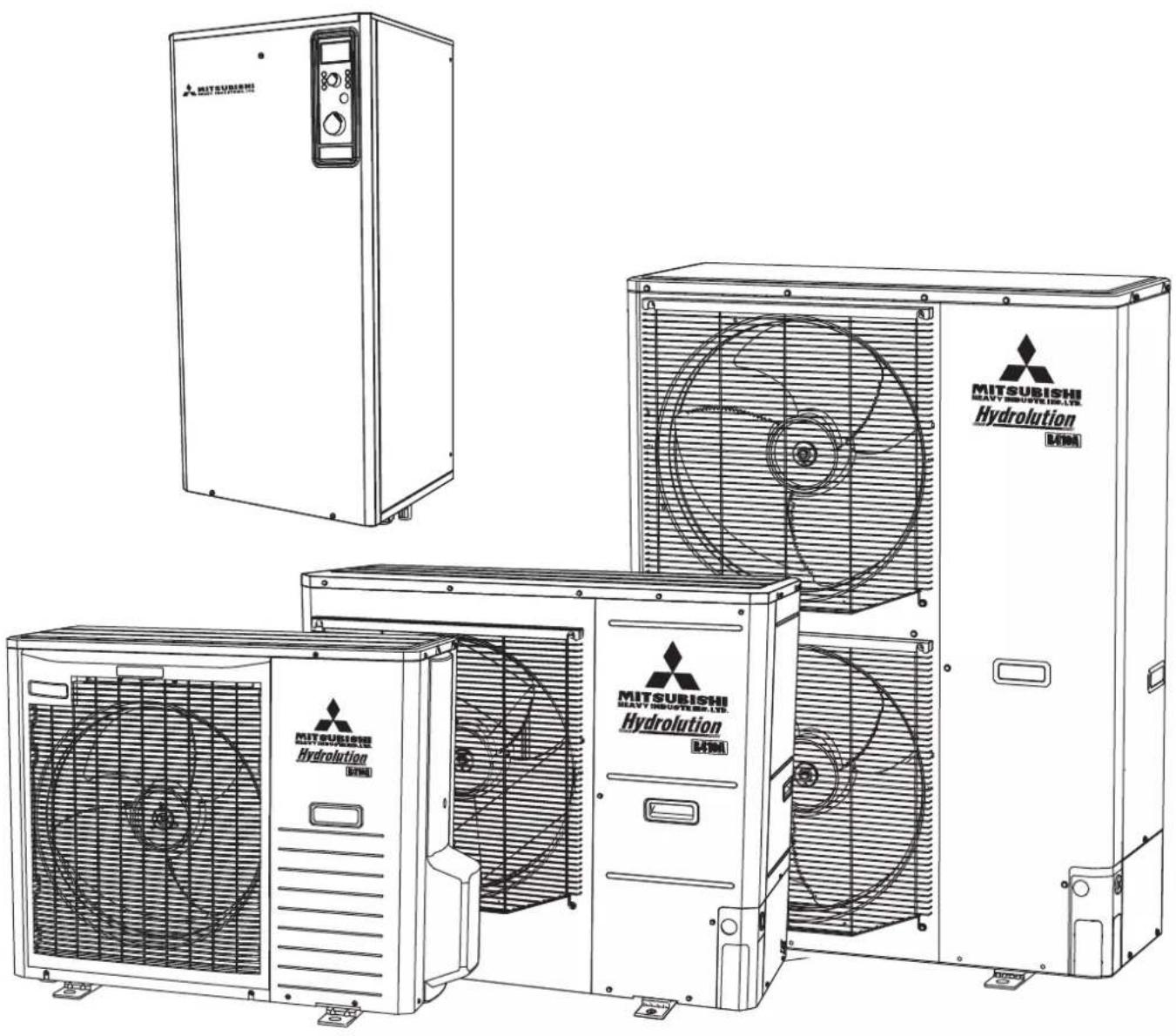
Hydrolution is a system for heating, cooling and producing hot water for small houses. The system consists of an outdoor nuit, which utilises the energy in the outdoor air and sends it to the indoor unit, which takes care of the regulation and heat distribution in the house.
In order to get the greatest benefit from the system Hydrolution you should read through the User's Manual.
Hydrolution is a quality system offering a long service life and reliable operation.
NOTE
Do not vent R410A into the atmosphere: R410A is a fluorinated greenhouse gas, covered by the Kyoto Protocol with a Global Warming Potential(GWP) = 1975.
Installation data
Completed by the installation engineer when the installation is installed
Installation data and installation check list on page 34 must be filled in by the installer in order for the warranty to apply.
| The Serial number, must always be stated in all correspondence with MHI. | |||
| Indoor unit: ____ Outdoor unit: ____ | |||
| Installation date | |||
| Check list, page 34, filled in □ | |||
| Installation engineers | |||
| Heating□Radiator Floor Fan convectorCooling□Other Floor Fan convector Not availableExternal heat source□Solar Gas Oil Wood Pellets ElectricityAccessories□Tank heater MII-RG 10 ESV22/28 VCC22/28 ACK22/28 | |||
| SettingsFill in the difference from default settings. | |||
| Menu Number Menu Type Description | Setting | ||
| ____________ | ____________ | ____________ | ____________ |
| ____________ | ____________ | ____________ | ____________ |
| ____________ | ____________ | ____________ | ____________ |
| Date____Signed____ | |||
This appliance is not intended for use by persons (including children) with reduced physical, sensory or mental capabilities, or lack of experience and knowledge, unless they have been given supervision or instruction concerning use of the appliance by a person responsible for their safety.
Children should be supervised to ensure that they do not play with the appliance.
Information about the installation
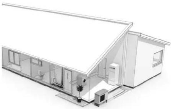
natural_image
Architectural line drawing of a modern two-story house with visible roof, door, and window (no text or symbols)Product information
Hydrolution is a complete modern heat pump system that offers effective technical energy saving and reduced carbon dioxide emissions. Heat production is safe and economical with integrated hot water heater, immersion heater, circulation pump and climate system in the indoor unit.
The heat is retrieved from the outdoor air through outdoor unit, where the refrigerant circulated in a closed piping system transfers the heat from the heat source (outdoor air) to indoor unit.
This eliminates the need for holes and coils in the ground.
Features of Hydrolution
■ Optimal annual heating factor thanks to the inverter controlled compressor.
■ Outdoor unit with compact dimensions.
■ Speed controlled system pump that supplies the heat pump with suitable system flow.
■ Optimized operating costs. The speed of the compressor is adjusted according to the demand.
■ Integrated coil water heater in indoor unit.
■ Integrated clock for scheduling extra hot water and temperature lowering/increasing the supply water temperature.
■ Prepared for control of two heating systems.
■ Integrated active cooling function.
■ Possible to connect external heat sources.
Principle of operation Hydrolution
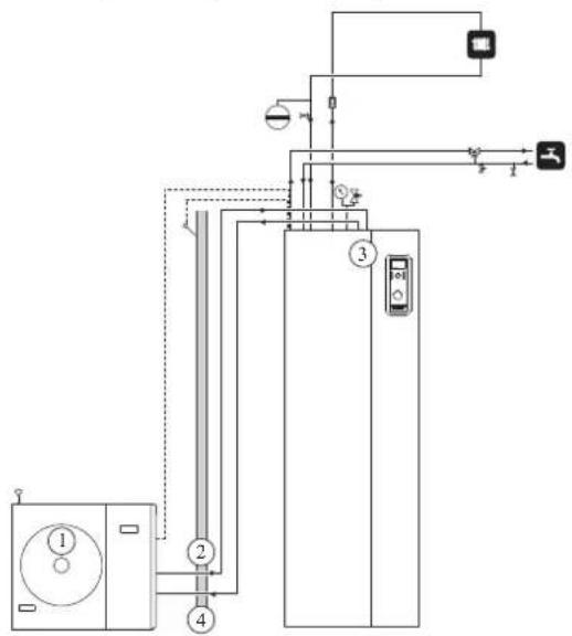
flowchart
graph TD
    A["Control Unit ①"] --> B["Valve ②"]
    B --> C["Valve ③"]
    C --> D["Sensor ④"]
    D --> E["Return Line"]
    E --> F["Output Line"]
    G["Sensor ⑤"] --> H["Feedback Line"]
    H --> I["Return Line"]
    I --> J["Return Line"]
    K["Return Line"] --> L["Return Line"]
Function
Hydrolution is a system that can produce heating, hot water and cooling.
The principle during heating can be simplified as follows:
- The refrigerant in outdoor unit takes the heat from the outdoor air and is compressed to higher temperature by the compressor.
- The hot refrigerant (now in gas state) is routed into indoor unit.
- The refrigerant releases the heat for further distribution in the system.
- The refrigerant (now in liquid state) is routed back to outdoor unit and the process is repeated.
By reversing the entire process, and thereby the refrigerant in outdoor unit takes the heat from the water and release the heat to the outdoor air, the heat pump can cool instead if necessary. Indoor unit determines when outdoor unit is to work and not to work, using the collated data from the temperature sensor. In the event of extra heat demands, indoor unit can connect additional heat source in the form of the internal immersion heater, or any connected external heat source.
Front panel, indoor unit
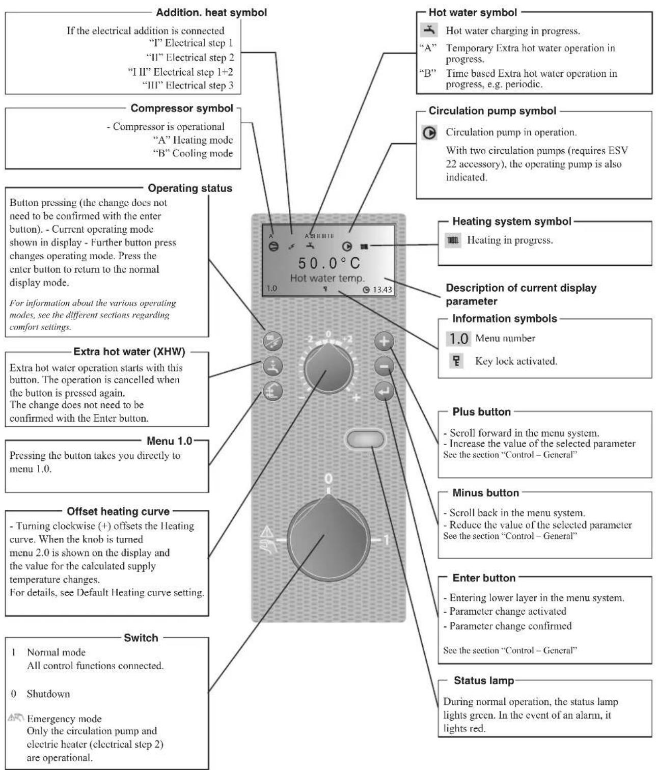
How to use the front panel
All the most common settings are made from the panel such as comfort etc. that you expect from the heat pump system to fulfil.
In order to make full use of it, certain basic settings must have been made (see page 11) and the installation in general is carried out according to the instructions.
Menu 1.0 (the temperature in the water heater) is normally shown on the display.

The plus and minus buttons and the enter button are used to scroll through the menu system as well as to change the set value in some menus.


Menu types (Menu 8.1.1)
Control is classified into different menu types depending on how "deep" into the controls you need to go.
■ Normal [N]: The settings you as a customer often need.
■ Extended [U]: Shows all detailed menus except the service menus.
Quick movement
To quickly return to the main menu from a sub menu, press
the following button:
Key lock
A key lock can be activated in the main menus by simultaneously
pressing the and the buttons. The key symbol will
then be shown on the display.
The same procedure is used to deactivate the key lock.
Language setting (Menu 8.1.2)
Language used in the display can be chosen in menu 8.1.2.
Comfort setting heating
General
The indoor temperature depends on several factors.
■ Sunlight and heat emissions from people and household machines are normally sufficient to keep the house warm during the warmer parts of the year.
■ When it gets colder outside, the heating system must be started. The colder it is outside, the warmer radiators and under floor heating systems must be.
Controlling heat production
Normally, the heat pump heats the water (heating medium) to the temperature required at a certain outdoor temperature. This occurs automatically on the basis of the collected temperature values from the outdoor sensor and sensors on the lines to the radiators (supply water sensors). Extra accessories such as room sensors, can influence the temperature.
In order to operate the system properly, the correct settings must be made on the heat pump first, see the section "Default Heating curve setting".
The outdoor sensor (mounted on an exterior wall of the house) senses variations in the outdoor temperature early on, sends the information to the heat pump control computer and heating operation is started. It does not have to be cold inside the house before the control system is activated. As soon as the temperature drops outside, the temperature of the water to the radiators (supply temp.) inside the house is increased automatically.
The heat pumps flow temperature (menu 2.0) will hover around the theoretical required value, which is in brackets on the display.
Temperature of the heating system
The temperature of the heating system in relation to the outdoor temperature can be determined by you by selecting a heat curve and by using the “Offset heating curve” knob on the heat pump’s front panel.
Operating status

The “Operating mode” button is used to set the required operating mode.
The change does not need to be confirmed with the enter button.
The current operating mode is shown on the front panel display when the button is pressed and the mode changes when you continue to press the button.
The display returns to the normal display mode once the enter button is pressed.
The electric heater is only used for anti-freeze if it is deactivated in the menu system for all operating modes.
There are different operating modes to choose:
- "Auto"
Indoor unit automatically selects the operating mode by taking the outdoor temperature into account. This means that the operating mode switches between "Heating" and "Hot water".
The circulation pump is permitted to operate when there is a need.
- "AutoC"*
Indoor unit selects operating mode automatically (cooling can also be selected now) by the outdoor temperature. This means that the operating mode switches between “Heating”, “Cooling” and “Hot water”.
The circulation pump is permitted to operate when there is a need.
- Heating
Only heating and hot water mode.
The circulation pump is in operation the entire time. Electirc heater is energized if necessary.
- Cooling*
Heat pump is used for cooling only if electric heater use is allowed. Otherwise, it is used for both cooling and hot water. The circulation pump is in operation the entire time.
- Hot water
Only hot water is produced.
Only the compressor is operational.
- Add. Heat only
Heat pump is not operational. The function is activated/deactivated by pressing in the “operating mode button” for 7 seconds.
* To use the cooling functions, the system must be designed to withstand low temperatures and cooling must be activated in menu 9.3.3.
Changing the room temperature manually
If you want to temporarily or permanently increase or lower the indoor temperature, turn the “Offset heating curve” knob clockwise to increase or anticlockwise to lower. One line approximately represents 1 degree change in room temperature.
NOTE
An increase in the room temperature may be inhibited by the radiator or underfloor heating thermostats, if so these must be set at 0.
Default Heating curve setting
The basic heating is set using menu 2.1.2 and with the “Heating curve offset” knob.
If the room temperature does not reach the target, readjustment may be necessary.
If you do not know the correct settings, use the basic data from the automatic heating control system diagram on the right.
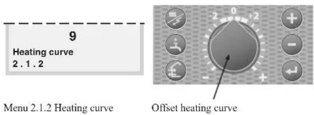
Heating curve offset for system 2 can be made in menu 3.1
NOTE
Wait one day between settings so as to stabilise the temperatures.
Setting with diagrams
The diagram shows the relation between the outdoor temperature in the area and the target supply water temperature of the heating system. This is set under menu 2.1.2, "Heating curve". Limitations, which are not in the diagrams, can be set in the control system's permitted min and max temperatures. (See menu 2.1.4 and 2.3 as well as 3.3 and 3.4)
Heating curve offset -2
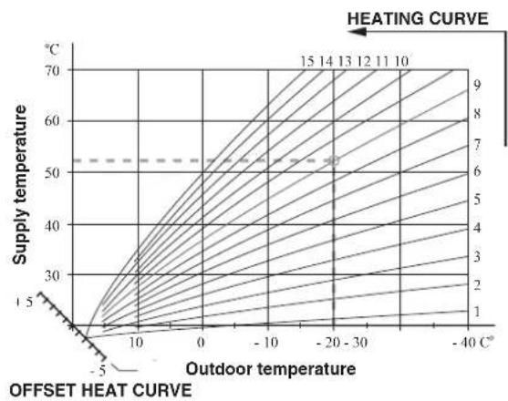
line
| Outdoor temperature | Supply temperature | Value | | ------------------- | ------------------ | ----- | | -5 | 1 | 1 | | 0 | 30 | 2 | | -10 | 40 | 3 | | -20 | 50 | 4 | | -30 | 60 | 5 | | -40 | 70 | 6 | | -5 | 1 | 7 | | 0 | 30 | 8 | | -10 | 40 | 9 | | -20 | 50 | 10 | | -30 | 60 | 11 | | -40 | 70 | 12 | | -5 | 1 | 15 | | 0 | 30 | 15 | | -10 | 40 | 15 | | -20 | 50 | 15 | | -30 | 60 | 15 | | -40 | 70 | 15 |Heating curve offset 0
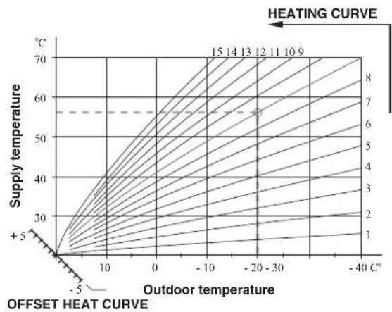
line
| Outdoor temperature | Supply temperature | HEATING CURVE | | ------------------- | ------------------ | ------------- | | -5 | +5 | 1 | | 0 | 30 | 2 | | -10 | 40 | 3 | | -20 | 55 | 4 | | -30 | 60 | 5 | | -40 | 70 | 6 | | -40 | 70 | 7 | | -40 | 70 | 8 | | -40 | 70 | 9 | | -40 | 70 | 10 | | -40 | 70 | 11 | | -40 | 70 | 12 | | -40 | 70 | 13 | | -40 | 70 | 14 | | -40 | 70 | 15 |Heating curve offset +2
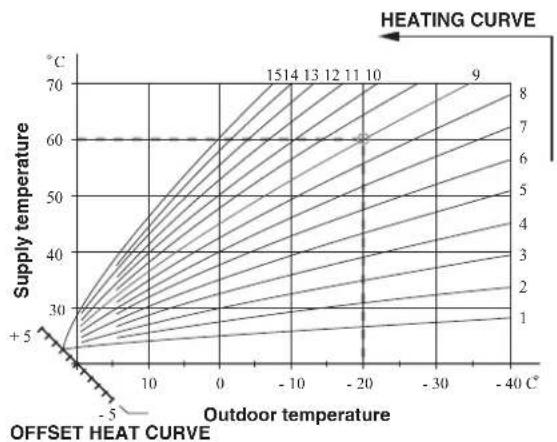
line
| Outdoor temperature | Supply temperature | HEATING CURVE | | ------------------- | ------------------ | ------------- | | 0 | 30 | 1 | | -10 | 60 | 2 | | -20 | 70 | 3 | | -30 | 60 | 4 | | -40 | 50 | 5 | | -5 | 40 | 6 | | -10 | 50 | 7 | | -20 | 60 | 8 | | -30 | 50 | 9 | | -40 | 40 | 10 | | -5 | 30 | 11 | | -10 | 40 | 12 | | -20 | 50 | 13 | | -30 | 60 | 14 | | -40 | 50 | 15 |Readjusting the default settings
If the room temperature does not reach the target, readjustment may be necessary.
Cold weather conditions
- When the room temperature is too low, the “Heating curve” value is increased in menu 2.1.2 by one increment.
- When the room temperature is too high, the “Heating curve” value is decreased in menu 2.1.2 by one increment.
Warm weather conditions
If the room temperature is low, increase the “Heating curve offset” setting by one step clockwise.
If the room temperature is high, reduce the “Heating curve offset” setting by one step anti-clockwise.
Heating system 2
If the heating system has two different type of emitter like radiator and under floor heating, it is possible to set two different calculated supply temperature. System 1 for higher supply temperature can be set in menu 2.1.0, and system 2 for lower supply temperature can be set in menu 3.0.
Vacation set back
When you are away from home for a long time, it is possible to set the target supply water temperature for heating lower than usual to save energy consumption. Also, it is possible to cancel hot water operation during the period.
For details, see menu 7.5.0 Vacation set back.
Silent mode
If you like to reduce noise from outdoor unit, it is possible to do by reducing the compressor speed and fan speed in outdoor unit. For details, see menu 7.6.0 Silent mode.
Comfort setting with room sensor
If MH-RG10 is installed, operation mode is chosen not only by outdoor temperature but also by room temperature.
Upper limit of the outdoor temperature to operate in Heating mode can be set in menu 8.2.3 Stop temp Heating.
Lower limit of the outdoor temperature to operate in Cooling mode can be set in menu 8.2.4 Start temp Cooling.
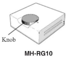
Target room temperature can be adjusted by turning the knob on MH-RG10, and it is displayed in menu 6.3.
For details, see instruction manual for MH-RG10. The below figure shows an example of mode transition.
NOTE
Mode transition wouldn't happen even if MH-RG10 is installed in case Heating or Cooling mode is chosen. Choose Auto or AutoC in case room sensor is used.
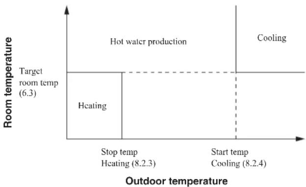
line
| Temperature Level | Room Temperature (°C) | | :--- | :--- | | Hot water production | 6.3 | | Cooling | 8.24 | | Heating | 8.23 | | Stop temp | 8.23 | | Start temp | 8.24 | | Target room temp (6.3) | 6.3 |Mode transition (in case AutoC is chosen)
Comfort setting cooling
General
In the default setting, cooling operation is not allowed. In order to activate, change the setting on the menu 9.3.3 Cooling system to "On".
NOTE
The climate system must manage cooling operation. Setting must be made by the installer when commissioning the system.
Settings must be made by the installer when commissioning the system.
If a room sensor is connected, it starts and stops cooling based on both the room and the outdoor temperature. The lowest calculated supply water temperature is set in menu 2.2.4.
Cooling operated from the outdoor sensor in operating mode AutoC
If the cooling system is set to "On" in menu 9.3.3 and the outdoor temperature is greater or equivalent to the set start temperature for cooling in menu 8.2.4, cooling starts.
Cooling stops when the outdoor temperature drops below the set value minus the set value in menu 8.2.5.
The calculated supply water temperature is determined from the selected cooling curve in menu 2.2.2 and the offset for cooling curve, menu 2.2.1. Limitations, which are not in the diagram, are included in the control system's permitted min temperature.
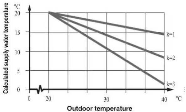
line
| Outdoor temperature (°C) | k=1 | k=2 | k=3 | | ------------------------ | ----- | ----- | ----- | | 0 | 20.0 | 20.0 | 20.0 | | 20 | 18.0 | 17.0 | 15.0 | | 40 | 15.0 | 9.0 | 2.0 |Comfort setting hot water
The integrated water heater is a coil model and is heated by circulating water, which is heated by the heat pump.
During “normal” consumption it is enough to run the heat pump to supply the different tapping points of the house with hot water. The temperature of the hot water in the water heater then varies between the set values.
Under section 1.0 [N] Hot water temp. on page 25 there is a complete description of menu settings for hot water temperatures.
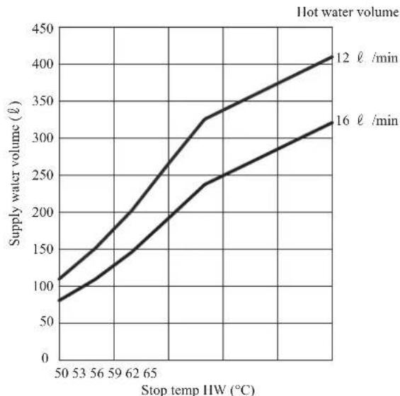
Available volume
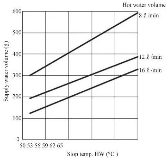
line
| Stop temp. HW (°C) | 8 ℓ /min | 12 ℓ /min | 16 ℓ /min | | ------------------ | -------- | --------- | --------- | | 53 | 300 | 190 | 120 | | 65 | 400 | 270 | 180 | | 65 | 600 | 390 | 280 |
line
| Stop temp HW (°C) | 12 ℓ /min | 16 ℓ /min | | ----------------- | --------- | --------- | | 50 | 100 | 80 | | 53 | 120 | 100 | | 56 | 140 | 120 | | 59 | 160 | 140 | | 62 | 180 | 160 | | 65 | 200 | 180 | | 68 | 240 | 220 | | 70 | 320 | 240 | | 72 | 340 | 260 | | 74 | 360 | 280 | | 76 | 380 | 300 | | 78 | 400 | 320 | | 80 | 420 | 340 |MT500
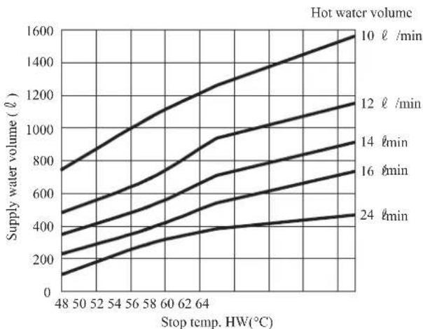
*These graphs are based on the following conditions :
Inlet water temperature : 15°C
Outlet water temperature : 40°C
Outdoor air temperature : 7°C
Hot water Supply is unlimited in case 8 ℓ/min at the condition as the capacity is bigger than hot water supply.
Prioritizing
When the water temperature in the tank drops, heat pump operation shifts to hot water production. In case there is demand for both hot water and heating/cooling for long time, operation mode is periodically switched between hot water and heating/cooling. For details, see menu 1.0 Hot water temp and 8.5.0 Period settings.
Extra Hot Water
In all “Extra hot water” functions, the temperature of the hot water increases temporarily. The temperature is first increased to an adjustable level by the compressor (menu 1.5) and then the electric heater is energized until the water temperature reaches the stop temperature (menu 1.4).
Temporary “Extra hot water” is activated manually, whilst time based extra hot water is activated using the settings made in the control computer.
When:
■ “A” appears above the 📁 icon, temporary extra hot water is active.
■ "B" appears above the icon, time based extra hot water is active.
NOTE
“Extra hot water” usually means that the electric heater is activated regardless of Allow add heat setting (menu 8.2.1) and therefore increases the electrical consumption.
"Extra hot water" can be activated in three different ways:
1. Periodic time based extra hot water
Interval between extra hot water operation is selected in menu 1.7. Menu 1.8 shows when the next extra hot water operation is due.
The increased temperature is maintained by the electric heater for one hour.
2. Schedule time based extra hot water
The start and stop times for the day of the week when the extra hot water operation is required are set in the sub menus to menu 7.4.0.
The increased temperature is maintained by the electric heater for the selected period.
3. Temporary extra hot water
Extra hot water operation starts when Extra hot water button is pressed, and it is kept for 3 hours. The operation is cancelled when the button is pressed again during the period.
The increased temperature is maintained by the electric heater until the period of time has expired.
NOTE
Heat pump will not start until Extra hot water period finishes. It may cause insufficient hot water supply if big demand comes.
Maintenance
Hydrolution requires minimal maintenance after commissioning. Hydrolution contains many components and is why monitoring functions are integrated to help you.
If something abnormal occurs, a message appears about malfunctions in the form of different "alarm" texts in display.
Checking the safety valves in indoor unit
Indoor unit has been equipped with a safety valve for the water heater as well as a safety valve for the climate system by the installer.
For HT30, a safety relief valve is supplied with tank unit and the valve is installed to water pipe by installer.
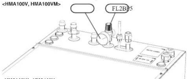
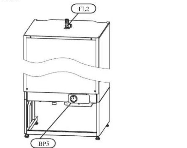
The climate system's safety valve
MT500
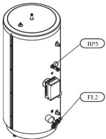
The climate system's safety valve (FL2) must be completely sealed. Checks must be carried out regularly as follows:
■ Open the valve.
- Check that water flows through the valve. If this does not happen, replace the safety valve.
■ Close the valve again.
■ The heating system may need to be refilled after checking the safety valve, see the section “Filling the heating system”.
Hot water heater safety valve
The water heater's safety valve sometimes releases a little water after hot water usage. This is because the cold water, which enters the heater to replace the hot water, expands when heated causing the pressure to rise and the safety valve to open.
Also check the water heater safety valve regularly. The appearance and location of the safety valve differs between different installations. Contact your installer for information.
Pressure gauge in indoor unit
The working range of the heating system is normally 0.5 - 1.5 bar when the system is closed. Check this on the pressure gauge (BP5).
Emptying the hot water heater
The water heater is of the coil type and is drained using the siphon principle. This can be done either via the drain valve on the incoming cold water pipe or by inserting a hose into the cold water connection.
Emptying the vessel
Contact your installer if the vessel in indoor unit needs emptying.
Maintenance of outdoor unit
Outdoor unit is equipped with control and monitoring equipment, however some exterior maintenance is still necessary.
Make regular checks throughout the year that the inlet grille is not clogged by leaves, snow or anything else. During the cold months of the year, check to make sure that there isn't a build up of ice or frost under outdoor unit. Strong wind combined with heavy snowfall can block the intake and exhaust air grilles. Make sure that there is no snow on the grilles.
Also check that the condensation water drain under outdoor unit is not blocked.
If necessary the outer casing can be cleaned using a damp cloth. Care must be exercised so that the heat pump is not scratched when cleaning. Avoid spraying water into the grilles or the sides so that water penetrates into outdoor unit. Prevent
outdoor unit coming into contact with alkaline cleaning agents.
⚠ WARNING!
Rotating fan
Saving tips
Your Hydrolution produces heat and hot water according to your needs. It also attempts to carry out all requirements with all available “aids” from the control settings made.
The indoor temperature is naturally affected by the energy consumption. Therefore, take care not to set a temperature higher than necessary.
Other known factors that affect the energy consumption are, for example, hot water consumption and the insulation level of the house, as well as the level of comfort you require.
Also remember:
■ Open the thermostat valves completely (except in the rooms that are to be kept cooler for various reasons, e.g. bedrooms).
Thermostat valves in the radiators and floor loops can negatively affect the energy consumption. They slow the flow in the heating system, which the heat pump wants to compensate with increased temperatures. It then works harder and consumes more electrical energy.
Dealing with comfort disruption
Use the following list to find and remedy any heating or hot water problems.
| Symptom Cause Action | ||
| Low hot water temperature or a lack of hot water | Circuit or main MCB tripped. Check and replace blown fuses. | |
| Heat pump and immersion heater do not heat. | Check and replace any blown circuit and main fuses. | |
| Possible earth circuit-breaker tripped. Reset the earth circuit-breaker, if the earth circuit-breaker trips repeatedly, call an electrician. | ||
| Switch (SF1) set to mode 0. Set the switch to 1. | ||
| Large hot water demand. Wait a few hours and | check if the hot water temperature rises. | |
| Too low start temperature setting on the control system. | Adjust the start temperature setting in menu 1.2. | |
| Low room temperature. | Possible earth circuit-breaker tripped. | Reset the earth circuit-breaker, if the earth circuit-breaker trips repeatedly, call an electrician. |
| Heat pump and immersion heater do not heat. | Check and replace any blown circuit and main fuses. | |
| Incorrect setting of “Heating curve, offset” and/or “Cooling curve, offset”. | Adjust the settings.Check menu 2.1.1, 2.1.2 for heating system 13.1, 3.2 for heating system 22.1.1, 2.2.2 for cooling system | |
| Stop temp heating setting is too low. Adjust the setting. Check menu 8.2.3 | ||
| Circuit or main MCB tripped. Check and replace blown fuses. | ||
| Heat pump in incorrect operating mode “Hot water” or “Cooling”. | Change operating mode to “Auto” or “AutoC”. | |
| The current limiter has restricted the current because many power consumers are being used in the property. | Switch off one/several of the power consumers. | |
| High room temperature. Incorrect setting of “Heating curve, offset” and/or “Cooling curve, offset”. | Adjust the settings.Check menu 2.1.1, 2.1.2 for heating system 13.1, 3.2 for heating system 22.1.1, 2.2.2 for cooling system | |
| Check and replace any blown circuit andmain fuses. | ||
| Check that the circuit breaker to the indoor unit is not off. | ||
| Set switch (SF1) to standby “ΔR”, | ||
The phenomena mentioned below is not malfunction.
| The air conditioning system sounds as if water is draining from it. | Sounds of rustling or gurgling may be heard when the operation is started, when the compressor is activated/deactivated during operation, or when the operation is stopped. These are the sounds of the refrigerant flowing through the system. |
| Sounds of rustling or gurgling may be heard from a stopped indoor unit. | These sounds can be heard when the air conditioning system is performing automatic control. |
| The air conditioning system cannot start operating again immediately after stopping. | Outdoor unit does not restart during the first 3 minutes after stopping operation. This is because a circuit for protecting the compressor is activated (the fan is operating during this period). |
| The outdoor unit discharges water or steam during heating operation. | Water or steam is discharge during defrosting operation which removes frost built up on the surface of the heat exchanger in the outdoor unit in heating mode. |
| The outdoor unit fan is not running even when the system is in operation. | The fan speed is automatically controlled according to the ambient temperature. It may be stopped in high ambient temperature in case of heating, and in low ambient temperature in case of cooling. Also, the fan is stopped during defrosting operation. REQUESTS The fan will suddenly begin to operate even if it is stopped. Do not insert finger and/or stick. |
| Hissing sounds are heard when the operation is stopped or during defrost operation. | These sounds are generated when the refrigerant valve inside the air conditioning system is activated. |
Operating mode "Add. heat only"
In the event of malfunctions that cause a low indoor temperature, you can normally activate “Add. heat only” in indoor unit, which means that heating only occurs with the immersion heater.
Activate the mode by holding in the operating mode button

for 7 seconds.
Note that this is only a temporary solution, as heating with the immersion heater does not make any savings.
Emergency mode
Emergency mode is activated by setting the switch to “” It is used when the control system and thereby operating mode “Add. heat only” do not function as they should. Emergency mode is activated by setting switch (SF1) to “”
The following applies in emergency mode:
■ The front panel is not lit and the control computer in indoor unit is not connected.
■ Outdoor unit is off and only the circulation pump and immersion heater in indoor unit are active.
■ An electrical step of 4 kW is connected. The immersion heater is controlled by a separate thermostat (BT30).
■ The automatic heating control system is not operational, so manual shunt operation is required. Call installer.
Alarm indications
There are many monitoring functions integrated in Hydrolution. To alert you to any malfunctions, the control computer transmits alarm signals that can be read from the front panel display.
What happens in the event of an alarm?
■ The background lighting in the display starts flashing and the status lamp lights red.
■ Some alarms change operating mode to “Add. heat only.” and reduce the supply temperature to the minimum permitted temperature to notify you that something is wrong.
Different types of alarms
■ Alarms with automatic reset (do not need to be acknowledged when the cause has disappeared).
■ Existing alarms that require corrective action by you or the installer.
Recommended actions
- Read off which alarm has occurred from the heat pump' display.
- As a customer you can rectify certain alarms. See the table below for relevant actions. If the alarm is not rectified, or is not included in the table, turn off the switch(SF1) to 0 and contact your installer.
| Alarm descriptionAlarm text on the display | Check/remedy before installers/service technicians are called | |
| Tripped low pressure sensor.LP-ALARM | Check that the thermostats for the radiators/under-floor systems are not closed. | |
| Tripped high pressure sensor.HP-ALARM | Check that the thermostats for the radiators/under-floor systems are not closed. | |
| OU power failure / OU Com. error | Outdoor unit not powered / Communication cut | Check that any circuit breakers to the outdoor unit are not off. |
| Display not lit | Check and replace any blown circuit and main fuses. | |
| Check that the circuit breaker to the indoor unit is not off. | ||
| Check that the switch (SF1) is in normal position (1). |
Resetting alarms
No harm in resetting an alarm. If the cause of the alarm remains, the alarm recurs.
■ When an alarm has been triggered, it can be reset by switching indoor unit off and on using the switch (SF1).
- When the alarm cannot be reset using the switch (SF1), the operating mode, “Add. heat only”, can be activated to resume a normal temperature level in the house. This is most easily carried out by holding the “Operating mode” button in for 7 seconds.
NOTE
Recurring alarms mean that there is a fault in the installation.
Contact your installer!
Control
Display
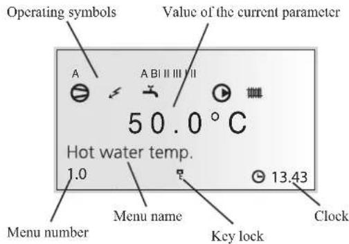
Menu types
Control is classified into different menu types depending on how "deep" into the controls you need to go.
■ Normal [N]: The settings you as a customer often need.
■ Extended [U]: Shows all detailed menus except the service menus.
Menu management

The Plus button is used to move forward to the next menu on the current menu level and to increase the value of the parameter in menus where this is possible.
The Minus button is used to move back to the previous menu on the current menu level and to decrease the value of the parameter in menus where this is possible.

The Enter button is used to select submenus of the current menu, to permit parameters to be changed and to confirm any changes to parameters. When the menu number ends with a zero this indicates that there is a submenu.
Changing parameters
In order to change a parameter (value):
- Access the required menu.
- Press ← button, the numerical value starts to flash.
- Increase or decrease using + or buttons.
- Confirm by pressing ← button.
- Menu 1.0 is automatically displayed again 30 minutes after the last button is pressed.
Example
Changing the heating curve, menu 2.1.
- The starting point is menu 1.0.
- Press + button to move to menu 2.0.
- Press ← button to move to menu 2.1.
-
Press ← button to change the value.
-
Change the value by pressing + or buttons.
-
Confirm the selected value by pressing ↻ button.
-
Press button to access menu 1.0.
Menu tree
1.0 [N] Hot water temp.
| 1.1 [N] Max HW/Peroid time |
| 1.2 [N] Start temperature HW |
| 1.3 [N] Stop temperature HW |
| 1.4 [U] Stop temperature XHW |
| 1.5 [U] Heat pump stop XHW |
| 1.6 [U] Max heat p. time XHW |
| 1.7 [U] Interval XHW |
| 1.8 [U] Next XHW action |
| 1.9 [U] HW run time |
| 1.12 [N] Return |
2.0 [N] Supply temp.
| 2.1.1 [N] Offset heating/Total2.1.0 [N] Heating settings | |
| 2.1.2 [N] Heating curve | |
| 2.1.3.1 [U] Supply temp.at +202.1.3.0 [U] Ow | |
| 2.1.3.2 [U] Supply temp.at -20 | |
| 2.1.3.3 [U] Buckling temperature | |
| 2.1.3.4 [U] Supply t. at buckl. | |
| 2.1.3.5 [U] Return | |
| 2.1.4 [U] Min supply heating | |
| 2.1.5 [U] Circ-pump speed heat | |
| 2.1.6 [N] Return | |
| 2.2.1 [N] Offset cooling/Total2.2.0 [N] Cooling settings | |
| 2.2.2 [N] Cooling curve | |
| 2.2.3.1 [U] Supply temp.at +202.2.3.0 [U] Ow | |
| 2.2.3.2 [U] Supply temp.at +40 | |
| 2.2.3.3 [U] Return | |
| 2.2.4 [U] Min supply cooling | |
| 2.2.5 [U] Circ-pump speed cool | |
| 2.2.6 [N] Return | |
| 2.3 [U] Max supply temp. | |
| 2.4 [U] External adjustment | |
| 2.5 [U] Supply/Return temp. | |
| 2.6 [U] Degree minutes | |
| 2.7 [N] Return | |
Control
3.0 [N] Supply temp. 2
| 3.1 [N] Offset heating/Tot 2 | |
| 3.2 [N] Heating curve 2 | |
| 3.3 [U] Min supply temp. 2 | |
| 3.4 [U] Max supply temp. 2 | |
| 3.5 [U] External adjust. 2 | |
| 3.6.0 [U] Own heating curve 2 | 3.6.1 [U] Supply temp.at +20 |
| 3.6.2 [U] Supply temp.at -20 | |
| 3.6.3 [U] Buckling temperature | |
| 3.6.4 [U] Supply t. at buckl | |
| 3.6.5 [U] Return | |
| 3.7 [U] Supply/Return temp 2 | |
| 3.8 [N] Return | |
4.0 [N] Outdoor temp.
| 4.1 [N] Outdoor avg. temp. |
| 4.2 [U] Outdoor filter time |
| 4.3 [U] Outdoor avg. 1min. |
| 4.4 [N] Return |
5.0 [N] Heat pump
| 5.1 [N] Number of starts | 6.1 [U] Room | |
| 5.2 [N] Run time compressor | 6.2 [U] Heat | |
| 5.3 [U] Time to start | 6.3 [N] Room | |
| 5.4 [U] Outdoor temp. Tho-A | 6.4 [U] Room | |
| 5.5 [U] Heat Ex Tho-R1 | 6.5 [U] Room | |
| 5.6 [U] Heat Ex Tho-R2 | 6.6 [N] Return | |
| 5.7 [U] Suction temp. Tho-S | *Requires ac | |
| 5.8 [U] Hot gas Tho-D | ||
| 5.9 [U] Liquid line temp. | ||
| 5.10 [U] Condensor out / max | ||
| 5.11 [U] HP | ||
| 5.12 [U] LPLPT | ||
| 5.13 [U] Fan speed | ||
| 5.14.1 [U] OU current CT5.14.0 [U] CompFreq act/set | ||
| 5.14.2 [U] Inverter temp Tho-IP | ||
| 5.14.3 [U] Return | ||
| 5.16 [N] Return | ||
6.0 [N] Room temperature*
| 6.1 [U] Room compensation |
| 6.2 [U] Heating system |
| 6.3 [N] Room temp. setpoint |
| 6.4 [U] Room temp avg. 1min |
| 6.5 [U] Room integrator time |
| 6.6 [N] Return |
*Requires accessory and activation in menu 9.3.6.
| 7.0 [N] Clock | 8.0 [N] Other adjustments | ||
| 7.1 [N] Date | 8.1.1 [N] Menu type8.1.0 [N] Display | ||
| 7.2 [N] Time | |||
| 7.3.1 [U] Set back time7.3.0 [U] Temp set back | 8.1.2 [N] Language | ||
| 8.1.3 [N] Display contrast | |||
| 7.3.2 [U] Set back temp +/- | 8.1.4 [N] Light intensity | ||
| 7.3.3 [U] Heating systcm | 8.1.5 [N] Return | ||
| 7.3.4 [U] Return | 8.2.1 [N] Allow add. hcat8.2.0 [N] O | ||
| 7.4.1 [U] XHW Monday7.4.0 [U] Extra hot water | 8.2.2 [N] Add. heat only | ||
| 7.4.2 [U] XHW Tuesday | 8.2.3 [U] Stop temp. heating | ||
| 7.4.3 [U] XHW Wednesday | 8.2.4 [U] Start temp. cooling | ||
| 7.4.4 [U] XHW Thursday | 8.2.5 [U] Hysteresis | ||
| 7.4.5 [U] XHW Friday | 8.2.6 [N] Return | ||
| 7.4.6 [U] XHW Saturday | 8.3.1 [U] Fuse size8.3.0 [U] Current | ||
| 7.4.7 [U] XHW Sunday | |||
| 7.4.8 [U] Return | 8.3.2 [U] Max. electric power | ||
| 8.3.3 [U] Current phase 1 | |||
| 7.5.1 [U] Vacation begins7.5.0 [U] Vacation set back | 8.3.4 [U] Current phase 2 | ||
| 7.5.2 [U] Vacation ends | 8.3.5 [U] Current phase 3 | ||
| 7.5.3 [U] Heating system | 8.3.6 [U] Transform. ratio EBV | ||
| 7.5.4 [U] Offset heating curve | 8.3.7 [U] Return | ||
| 7.5.5 [U] HW off | 8.5.1 [U] Period time8.5.0 [U] Period | ||
| 7.5.6 [U] Return | |||
| 7.6.0 [N] Silent mode | 7.6.1 [N] Silent mode time | 8.5.2 [U] Max time for HW | |
| 8.5.3 [U] Return | |||
| 7.6.2 [N] Return | 8.6 [N] Return | ||
| 7.7 [N] Return | |||
Main menus
Menu 1.0 [N] Hot water temp.
The current hot water temperature in the vessel is shown here.
Figure on left shows the one in the middle and right one in brackets shows the one on the bottom.
Menu 2.0 [N] Supply temp.
The current supply temperature for the heating system is shown here with the calculated supply temperature in brackets.
Menu 3.0 [N] Supply temp. 2
The current supply temperature for heating system 2 is shown here with the calculated supply temperature in brackets.
Menu 4.0 [N] Outdoor temp.
The current outdoor air temperature is displayed here.
Menu 5.0 [N] Heat pump
The outdoor operation data are shown in the sub-menus to this menu.
The following text appears in the display.
| MeansText | |
| Off | Shownwhenthereisnocompressordemand andnoncofthefollowingapply. |
| On | Shownduringnormaloperationwiththecompressor. |
| Shownwhilethecompressorisrunning.Initiates | |
| Com.problem | Shownintheeventoftemporarycommunicationproblems. |
| Shownduringdefrost.Defrosting | |
| Oilreturn | Shownwhenthecompressorisrotatedtobelubricated. |
| Protection | Shownwhenthecompressorisinsomeform ofprotectionorduringastartdelayof30minutes. |
| Shutdown | Shownintheeventofanalarm,tariffBor OperatingmodeAdditiononly. |
| Stopped | Shownwhentheoutdoortemperatureisoutsidethecompressor’sworkingrange(toohigh ortoolowtemperature). |
Menu 6.0 [N] Room temperature
The room temperature is shown here and the set room temperature in brackets. The factor for the room sensor and heating system to control are set in the sub-menus to this menu.
Menu 7.0 [N] Clock
The date and time are set in the submenus of this menu. Different temperature reductions and increases at selected times are also set from this menu.
Menu 8.0 [N] Other adjustments
The menu type, language, operating mode settings and load monitor reading are set in the sub-menus to this menu.
NOTE! These settings should only be made by persons with the necessary expertise.
[N] Normal, covers the normal user's needs.
[U] Extended, shows all menus except the service menus.
1.0 [N] Hot water temp.
Menu 1.1 [N] Max HW/Period time
The time of the hot water period and the time for the whole period are shown here. Whole period is shown in brackets. Shown for both hot water charging and heating when necessary:
Time for Heating (Max.) when heating is in progress.
Time for Hot water (Max.) if hot water charging is in progress.
Menu 1.2 [N] Start temperature HW
The temperature when the heat pump starts hot water charging is set here.
Setting range: 25 - 55 °C
Menu 1.3 [N] Stop temperature HW
The temperature when the heat pump stops hot water charging is set here.
Setting range: 30 - 60 °C
Menu 1.4 [U] Stop temperature XHW
The desired temperature during extra hot water is set here.
Setting range: 40 – 65 °C
Menu 1.5 [U] Heat pump stop XHW
The desired stop temperature during extra hot water for the heat pump is set here.
Setting range: 40 – 60 °C
Menu 1.6 [U] Max heat p. time XHW
Here you select the maximum amount of time the heat pump can charge hot water for during extra hot water.
Setting range: 0 - 60 min
Menu 1.7 [U] Interval XHW
Periodic time based extra hot water is selected here.
Extra hot water is shut off at the value "Off". Extra hot water is started when the value is confirmed.
Setting range: 0 - 90 days
Menu 1.8 [U] Next XHW action
Time to the next periodic Extra hot water operation is shown here.
Menu 1.9 [U] HW run time
Shows how long hot water charging with the compressor has been in progress (accumulated).
Menu 1.12 [N] Return
Return to menu 1.0.
2.0 [N] Supply temp.
Menu 2.1.0 [N] Heating settings
Heating settings are made in the sub-menus for this menu.
Menu 2.1.1 [N] Offset heating/Total
The selected heating curve offset is shown here.
The total offset of the heat curve is also shown here. It includes schedule, outer compensation and any room control.
Note! The value is changed using the “Heating curve offset” knob.
Setting range: -10 - 10
Menu 2.1.2 [N] Heating curve
The selected heating curve is shown here. At value 0, the function “Own heat curve” is activated, see menu 2.1.3.0.
Setting range: 0 - 20
Menu 2.1.3.0 [U] Own heating curve
Here you can select your own curve definition. This is an individual linear curve with one break point. You select a break point and the associated temperatures.
Note! The “Heating curve” in menu 2.1.2 must be set to 0 to activate this function.
Menu 2.1.3.1 [U] Supply temp.at +20
The supply temperature at an outdoor air temperature of +20 °C is selected here.
Setting range: 0 - 80* °C
* Limited by menu 2.3 Max supply temp.
Menu 2.1.3.2 [U] Supply temp.at -20
The supply temperature at an outdoor air temperature of -20 ^ is selected here.
Setting range: 0 - 80* °C
* Limited by menu 2.3 Max supply temp.
Menu 2.1.3.3 [U] Buckling temperature
Here you select at what outside air temperature the break point shall occur.
Setting range: -15 – 15 °C
Menu 2.1.3.4 [U] Supply t. at buckl.
You set the calculated supply temperature for the break point here.
Setting range: 0 - 80* °C
* Limited by menu 2.3 Max supply temp.
Menu 2.1.3.5 [U] Return
Return to menu 2.1.3.0.
Menu 2.1.4 [U] Min supply heating
The set minimum level for the supply temperature to the heating system is shown here.
The calculated flow temperature never drops below the set level irrespective of the outdoor temperature, heating curve or its offset heating curve.
Setting range: 20 - 65 °C
Menu 2.1.5 [U] Circ-pump speed heat
The speed of the circulation pump during space heating is selected here.
Setting range: 1 - 100
Menu 2.1.6 [N] Return
Return to menu 2.1.0.
Menu 2.2.0 [N] Cooling settings
Cooling settings are made in the sub-menus for this menu.
Menu 2.2.1 [N] Offset cooling/Total
The selected cooling curve offset is changed here.
The total offset of the cooling curve is also shown here. It includes schedule, outer compensation and any room control.
Setting range: -10 - 10
Menu 2.2.2 [N] Cooling curve
The selected cooling curve is shown here. At value 0, the function “Own cooling curve” is activated, see menu 2.2.3.0.
Setting range: 0 - 3
Menu 2.2.3.0 [U] Own cooling curve
Here you can select your own curve definition.
Note! The cooling curve in menu 2.2.2 must be set to 0 to activate this function.
Menu 2.2.3.1 [U] Supply temp.at +20
The supply temperature at an outdoor air temperature of +20 °C is selected here.
Setting range: 0 - 25* °C
* Limited by menu 2.2.4 Min supply cooling.
Menu 2.2.3.2 [U] Supply temp.at +40
The supply temperature at an outdoor air temperature of +40 °C is selected here.
Setting range: 0 - 25* °C
* Limited by menu 2.2.4 Min supply cooling.
Menu 2.2.3.3 [U] Return
Return to menu 2.2.3.0.
Menu 2.2.4 [N] Min supply cooling
The set minimum level for the supply temperature to the cooling system is shown here.
The calculated flow temperature never drops below the set level irrespective of the outdoor temperature, cooling curve or its offset.
| HMA100 H | MS140VA HM | S140V | |
| Setting range (°C) 7-25 | 7-25 | 7-25 | ^*2 |
| Default value (°C) 10 | 18 | ^*1 | 18 |
*1 It is necessary to adjust the value for fancoil application. Recommended value is 10.
*2 Do not set the value lower than 18°C. It may cause water leak and damage your property or the product itself.
Menu 2.2.5 [N] Circ-pump speed cool
The speed of the circulation pump during cooling is selected here.
Setting range: 1 - 100
Menu 2.2.6 [N] Return
Return to menu 2.2.0.
Menu 2.3 [U] Max supply temp.
The set maximum level for the supply temperature to the heating system is shown here.
The calculated flow temperature never exceeds the set level irrespective of the outdoor temperature, heating curve or offset heating curve.
Setting range: 25 - 65 °C
Menu 2.4 [U] External adjustment
Connecting an external contact, for example, a room thermostat (accessory) or a timer allows you to temporarily or periodically raise or lower the room temperature. When the external contact is closed, the heating curve offset or cooling curve offset is changed by the number of steps shown here.
If room control is active there is a degree change to the set room temperature.
Setting range: -10 - 10
Menu 2.5 [U] Supply/Return temp.
The current supply and return line temperatures are shown here. Return temperature is shown in brackets.
Menu 2.6 [U] Degree minutes
Current value for number of degree-minutes. In addition, this value can be changed to accelerate the start of heating production or cooling.
Setting range: -32000 - 32000
Menu 2.7 [N] Return
Return to menu 2.0.
3.0 [N] Supply temp. 2
Menu 3.1 [N] Offset heating/Tot 2
The heating curve offset 2 is selected here.
The total offset of heat curve 2 is also shown here. It includes schedule, outer compensation and any room control.
Setting range: -10 - 10
Menu 3.2 [N] Heating curve 2
The selected heating curve is shown here. At value 0, the function “Own heat curve 2” is activated, see menu 3.6.0.
Setting range: 0 - 20
Menu 3.3 [U] Min supply temp. 2
The set minimum level for the supply temperature for heating system 2 is shown here.
The calculated flow temperature never drops below the set level irrespective of the outdoor temperature, heating curve or its offset.
Setting range: 10 - 65 °C
Menu 3.4 [U] Max supply temp. 2
The set maximum level for the supply temperature for heating system 2 is shown here.
The calculated flow temperature never exceeds the set level irrespective of the outdoor temperature, heating curve or its offset.
Setting range: 10 – 65 °C
Menu 3.5 [U] External adjust. 2
Connecting an external contact, for example, a room thermostat (accessory) or a timer allows you to temporarily or periodically raise or lower the room temperature. When the external contact is closed, the heating curve offset or the cooling curve offset is changed by the number of steps shown here.
If room control is active there is a degree change to the set room temperature.
Setting range: -10 - 10
Menu 3.6.0 [U] Own heating curve 2
Here you can select your own curve definition. This is an individual linear curve with one break point. You select a break point and the associated temperatures.
Note! The heating curve in menu 3.2 must be set to 0 to activate this function.
Menu 3.6.1 [U] Supply temp.at +20
The supply temperature at an outdoor air temperature of +20 °C is selected here.
Setting range: 0 - 80* °C
* Limited by menu 3.4 Max supply temp. 2.
Menu 3.6.2 [U] Supply temp.at -20
The supply temperature at an outdoor air temperature of -20 ^ is selected here.
Setting range: 0 - 80* °C
* Limited by menu 3.4 Max supply temp. 2.
Menu 3.6.3 [U] Buckling temperature
Here you select at what outside air temperature the break point shall occur.
Setting range: -15 – 15 °C
Menu 3.6.4 [U] Supply t. at buckl
You set the calculated supply temperature for the break point here.
Setting range: 0 - 80* °C
* Limited by menu 3.4 Max supply temp. 2.
Menu 3.6.5 [U] Return
Return to menu 3.6.0.
Menu 3.7 [U] Supply/Return temp 2
The present supply and return temperatures for heating system 2 are shown here. Return temperature is shown in brackets.
Menu 3.8 [N] Return
Return to menu 3.0.
4.0 [N] Outdoor temp.
Menu 4.1 [N] Outdoor avg. temp.
This menu shows the average outdoor temperature according to the set value in menu 4.2 (factory setting: 24h).
Menu 4.2 [U] Outdoor filter time
Here you select during how long the average temperature in menu 4.1 is calculated.
Setting range: 1 min, 10 min, 1h, 2h, 4h, 6h, 12h, 24h
Menu 4.3 [U] Outdoor avg. 1min.
Shows the average outdoor temperature over the last minute.
Menu 4.4 [N] Return
Return to menu 4.0.
5.0 [N] Heat pump
Menu 5.1 [N] Number of starts
The accumulated number of starts with the compressor in outdoor unit is shown here.
Menu 5.2 [N] Run time compressor
The accumulated time that the compressor has been used in outdoor unit is shown here.
Menu 5.3 [U] Time to start
Time until the compressor start in outdoor unit is shown in this menu.
Menu 5.4 [U] Outdoor temp. Tho-A
This menu shows the outdoor air temperature that the heat pump measures.
Menu 5.5 [U] Heat Ex Tho-R1
This menu shows the evaporator temperature in the heat pump at sensor Tho-R1.
Menu 5.6 [U] Heat Ex Tho-R2
This menu shows the evaporator temperature in the heat pump at sensor Tho-R2.
Menu 5.7 [U] Suction temp. Tho-S
This menu shows the suction gas temperature in the heat pump.
Menu 5.8 [U] Hot gas Tho-D
This menu shows the hotgas temperature in the heat pump.
Menu 5.9 [U] Liquid line temp.
This menu shows the liquid line temperature in the heat pump.
Menu 5.10 [U] Condensor out / max
Shows the current and max. allowed temperature after the condenser.
Menu 5.11 [U] HP
The current high pressure and corresponding temperature during heating are shown here. During cooling, the actual low pressure and corresponding temperature are shown.
Menu 5.12 [U] LP LPT
The current low pressure is shown here.
Menu 5.13 [U] Fan speed
No function.
Menu 5.14.0 [U] CompFreq act/set
The actual and set point value for the compressor frequency are shown here.
Menu 5.14.1 [U] OU current CT
The present phase current to outdoor unit is shown here.
Menu 5.14.2 [U] Inverter temp Tho-IP
The current inverter temperature is shown here.
Menu 5.14.3 [U] Return
Return to menu 5.14.0.
Menu 5.16 [N] Return
Return to menu 5.0.
6.0 [N] Room temperature\*
*Requires accessory and activation in menu 9.3.6.
Menu 6.1 [U] Room compensation
A factor is selected here that determines how much the calculated supply temperature is affected by the difference between the room temperature and the set room temperature. A higher value gives a greater change.
Setting range: 0 - 10.0
Menu 6.2 [U] Heating system
You select here whether the room sensor is valid for heating system 1 (menu 2.0) and/or heating system 2 (menu 3.0).
Setting range: Off, System 1, System 2, System 1+2
Menu 6.3 [N] Room temp. setpoint
The desired room temperature is shown here.
Setting range: 10 - 30 °C
Menu 6.4 [U] Room temp avg. 1min
Shows the average room temperature over the last minute.
Menu 6.5 [U] Room integrator time
Select the integration time for room control here.
Setting range: 0 - 120
Menu 6.6 [N] Return
Return to menu 6.0.
7.0 [N] Clock
Menu 7.1 [N] Date
The current date is set here.
Menu 7.2 [N] Time
Here the current time is set.
Menu 7.3.0 [U] Temp set back
Settings, e.g. for night reduction can be selected in the submenus to this menu.
Menu 7.3.1 [U] Set back time
The time for the set back operation, e.g. night reduction is chosen here.
Menu 7.3.2 [U] Set back temp +/-
Changes of the heat curve during set back operation period, e.g. the night reduction is set here.
Setting range: -10 - 10
Default value: 0
Menu 7.3.3 [U] Heating system
The heating system to apply the set back operation is selected here. If heating system 2 is present the menu can be set to "Off", "System 1", "System 2" or "System 1+2". In other cases only "Off" and "System 1" can be selected.
Setting range: Off, System 1, System 2, System 1+2
Menu 7.3.4 [U] Return
Return to menu 7.3.0.
Menu 7.4.0 [U] Extra hot water
Settings are made in the sub-menus of this menu when extra hot water is required on a specific day.
Menu 7.4.1 - 7.4.7 [U] XHW Monday - XHW Sunday
Here you select the period for respective days when extra hot water should be activated. Hours and minutes for both start and stop are shown. Equal values mean that extra hot water is not activated. Time can be set past midnight.
Setting range: 00:00 - 23:45
Menu 7.4.8 [U] Return
Return to menu 7.4.0.
Menu 7.5.0 [U] Vacation set back
Holiday settings are made in the sub-menus to this menu.
When the holiday function is active, the calculated supply line temperature is reduced according to the setting and hot water charging can be switched off.
When the holiday function is deactivated, the heat pump operates hot water for an hour, before periodic extra hot water is activated (even if periodic extra hot water is activated in menu 1.7).
Note! The holiday setting does not deactivate cooling.
Menu 7.5.1 [U] Vacation begins
The start date for holiday changing is set here. The date is changed by pressing the enter button. The holiday change starts applying at 00:00 on the selected date.
Same date in menu 7.5.1 and 7.5.2 deactivates the holiday function.
Menu 7.5.2 [U] Vacation ends
The end date for holiday changing is set here. The date is changed by pressing the enter button. The holiday change stops applying at 23:59 on the selected date.
Same date in menu 7.5.1 and 7.5.2 deactivates the holiday function.
Menu 7.5.3 [U] Heating system
The heating system to apply the vacation set back is selected here. If heating system 2 is present the menu can be set to "Off", "System 1", "System 2" or "System 1+2". In other cases only "Off" and "System 1" can be selected.
Setting range: Off, System 1, System 2, System 1+2
Menu 7.5.4 [U] Offset heating curve
How much the heating curve is to be offset during the holiday period is set here.
If the relevant heating system has a room sensor, the change is given in degrees.
Setting range: -10 - 10
Menu 7.5.5 [U] HW off
You can choose if hot water operation is cancelled during the holiday period
Setting range: No, Yes
Menu 7.5.6 [U] Return
Return to menu 7.5.0.
Menu 7.6.0 [N] Silent mode
Setting is made in the sub-menu of this menu if Silent mode is activated on a certain period.
When the silent mode is activated, maximum compressor speed and fan speed in outdoor unit is reduced in order to make the noise smaller.
Take note that the capacity is reduced by around 30% during silent mode.
It is valid in heating mode only.
Menu 7.6.1 [N] Silent mode time
Here you select the period when the silent mode should be activated. Hours and minutes for both start and stop are shown. Equal values mean that the silent mode is not activated. Time can be set past midnight.
Setting range: 00:00-23:45
Menu 7.6.2 [N] Return
Return to Menu 7.6.0
Menu 7.7 [N] Return
Return to menu 7.0.
8.0 [N] Other adjustments
Menu 8.1.0 [N] Display settings
Settings concerning language and menu type are set in the submenus to this menu.
Menu 8.1.1 [N] Menu type
The menu type is chosen here.
[N] Normal, covers the normal user's needs.
[U] Extended, shows all menus except the service menus.
[S] Service, shows all menus, returns to normal menu level 30 minutes after the last button was pressed.
NOTE
Incorrect settings in the service menus can damage the property and/or heat pump.
Setting range: N, U, S
Menu 8.1.2 [N] Language
Language settings are made here.
Menu 8.1.3 [U] Display contrast
The display's contrast is set here.
Setting range: 0 - 31
Menu 8.1.4 [U] Light intensity
The light intensity in idle mode is set here. Idle mode starts 30 minutes after the last button was pushed.
Setting range: 0=off, 1=low, 2=average.
Menu 8.1.5 [N] Return
Return to menu 8.1.0.
Menu 8.2.0 [N] Op. mode settings
Settings regarding auto mode can be made in the sub-menus to this menu.
Menu 8.2.1 [N] Allow add. heat
You can choose at which operating mode the electric heater is to be permitted to produce hot water and heat when needed.
Setting range: Off, Heating, Heating + Cooling, Cooling
Default values: Heating
Menu 8.2.2 [N] Add. heat mode
Selected if electric heater only is to be used to produce hot water and heat.
Setting range: Off, On
Menu 8.2.3 [U] Stop temp. heating
The average outdoor air temperature at which the heat pump (in auto mode) is to stop heat production.
When the average outdoor air temperature falls below Stop temp. heating - Hysteresis (menu 8.2.5) heating starts again.
Setting range: 1 - 43 °C
Menu 8.2.4 [U] Start temp. cooling
The average outdoor air temperature at which the heat pump (in autoC mode) is to start cooling.
When the average outdoor temperature exceed it, cooling starts.
When the average outdoor air temperature falls below Start temp. cooling - Hysteresis (menu 8.2.5) cooling stops.
Setting range: 10 - 43* °C
* Operable temperature range is 15 – 43 °C.
Menu 8.2.5 [U] Hysteresis
See menu 8.2.3 and menu 8.2.4. Also affects control with room sensor.
Setting range: 1.0 - 10.0
Menu 8.2.6 [N] Return
Return to menu 8.2.0.
Menu 8.3.0 [U] Current limiter
Settings and readings regarding the load monitor are set in the sub-menus to this menu.
Menu 8.3.1 [U] Fuse size
The setting selected on the PCB (AA22) switch (R24) is shown here.
Menu 8.3.2 [U] Max. electric power
The setting selected on the PCB (AA22) switch (R25) is shown here.
Menu 8.3.3 [U] Current phase 1
Measured current from phase 1 shown here. If the value falls below 2.8 A “low” is displayed.
Menu 8.3.4 [U] Current phase 2
Measured current from phase 2 shown here. If the value falls below 2.8 A “low” is displayed.
Menu 8.3.5 [U] Current phase 3
Measured current from phase 3 shown here. If the value falls below 2.8 A “low” is displayed.
Menu 8.3.6 [U] Transform. ratio EBV
The transfer value must be defined depending on the current transformers used for the PCB.
Setting range: 100 - 1250
Menu 8.3.7 [U] Return
Return to menu 8.3.0.
Menu 8.5.0 [U] Period settings
Time periods for heating and hot water production are set in the sub-menus for this menu.
Menu 8.5.1 [U] Period time
You can set the length of cycle time for hot water production and heating in case there is demand for both.
Setting range: 5 - 60 min
Menu 8.5.2 [U] Max time for HW
Here you select operation period for hot water of the period time. (8.5.1)
Setting range: 0 – 60 min
Menu 8.5.3 [U] Return
Return to menu 8.5.0.
Menu 8.6 [N] Return
Return to menu 8.0.
Checklist: Checks before commissioning
| CheckedNote | ||
| Non-return valve | Is it installed in right direction? | ☐ |
| Safety valve | Is it installed in cold water line? | ☐ |
| Mixer valve | Is it installed in right direction? | ☐ |
| ☐ | ||
| CheckedNote | ||
| System volume | Tank \_\_\_\_ + System \_\_\_\_ = Total \_\_\_\_ | ☐ |
| Safety valve | Is FL2 installed? | ☐ |
| Expansion vessel | Total system volume × 5% or more \_\_\_\_ | ☐ |
| Internal heater | Permitted/prohibited (Menu 8.2.1) | ☐ |
| External heat Source | Yes → Type \_\_\_\_ Setting (Menu 9.2.8) \_\_\_\_ No | ☐ |
| Heating system 2 | YesNo | ☐ |
| CheckedNote | ||
| Pipe system, condensation insulation | ☐ | |
| Reversing valve (QN12) Is it installed in right direction? | ☐ | |
| ☐ | ||
| CheckedNote | ||
| Pipe length (within 12m) | \_\_\_\_m | ☐ |
| Height difference (within 7m) | \_\_\_\_m | ☐ |
| Test pressurization | 41.5 bar | ☐ |
| Leak tracing | ☐ | |
| End pressure Evacuation | -1 bar or lower for one hour | ☐ |
| ☐ | ||
| CheckedNote | ||
| Property's main fuse | 3/1 phase \_\_\_\_A | ☐ |
| Group fuse | 3/1 phase \_\_\_\_A | ☐ |
| Current limiter/current sensor | Is it installed properly if the power supply is 3 phase? | ☐ |
| ☐ | ||
| CheckedNote | ||
| External circulation pump | Yes/No | ☐ |
| Buffer vessel | Yes/No Volume \_\_\_\_ | ☐ |
| Relief valve | Yes/No | ☐ |
| Room sensor | Yes/No TypeSetting (Menu 9.3.5, 9.3.6, 6.2) | ☐ |
| ☐ | ||
MEMO
MEMO
![MITSUBISHI HMS140V - Menu 8.6 [N] Return - 1](/content/2026/05/894593/images/debceee5eccd98b5b894f7e63eb0d093414f591e3ffbddc65417cf93cfc84683.jpg)
7 Roundwood Avenue, Stockley Park, Uxbridge, Middlesex, UB11 1AX, United Kingdom
Tel: +44-20-7025-2750
Fax: +44-20-7025-2751
http://www.mhiae.com
- Safety percautions
- General
- Information about the installation
- Front panel, indoor unit
- Comfort setting heating
- Comfort setting cooling
- Comfort setting hot water
- Maintenance
- Dealing with comfort disruption
- Alarm indications
- Control
- SAFETY PRECAUTIONS
- INSTALLATION PRECAUTIONS
- DANGER
- CAUTION
- Make sure to mount a leakage breaker
- Do not mount where flammable gas leakage can happen.
- Make sure to layout the drain pipe so that the water is completely drained.
- OPERATION PRECAUTIONS
- When the unit isn't used for a long term, cut off the power.
- Do not place any other electric appliances or household goods below or around the air conditioner.
- Do not touch the aluminum fin.
- Do not clean the inside of the indoor unit by yourself. Make sure to consult your dealer or user inquiry counter specified by our company.
- Do not place objects on the outdoor unit, nor mount on it.
- During the operation or maintenance, do not use an unstable footrest.
- During thunderstorm, stop the operation and turn off the switch.
- After several seasons of operating, ! inspections and maintenances are required except routine care and cleaning.
- Do not place any object around the outdoor unit, nor allow fallen leaves to pile up.
- Do not use with inlet/outlet grilles or other panel removed.
- Do not operate or stop the unit by using the power supply switch.
- Do not strain the remote control cord.
- Do not use water heater etc. near the indoor unit or remote control.
- Do not use the unit where powder or fiber is floating.
- Do not place objects under the unit which must avoid being exposed to water.
- PRECAUTIONS FOR RELOCATION OR REPAIRING
- Never perform any modification. Contact your dealer for repairing.
- If it is required to relocation and reinstall the unit, consult your dealer or a specialist.
- Before repairing or checking indoor unit, be sure to turn off "Indoor unit power supply breaker".
- Place the panels removed for repairing or checking on the stable spot.
- NOTE
- Installation data
- Completed by the installation engineer when the installation is installed
- Product information
- Features of Hydrolution
- Function
- How to use the front panel
- Menu 1.0 (the temperature in the water heater) is normally shown on the display.
- Menu types (Menu 8.1.1)
- Quick movement
- Key lock
- Language setting (Menu 8.1.2)
- Controlling heat production
- Temperature of the heating system
- Operating status
- Changing the room temperature manually
- Default Heating curve setting
- Setting with diagrams
- Readjusting the default settings
- Heating system 2
- Vacation set back
- Silent mode
- Comfort setting with room sensor
- Cooling operated from the outdoor sensor in operating mode AutoC
- Available volume
- Prioritizing
- Extra Hot Water
- "Extra hot water" can be activated in three different ways:
- Periodic time based extra hot water
- Schedule time based extra hot water
- Temporary extra hot water
- Checking the safety valves in indoor unit
- Hot water heater safety valve
- Pressure gauge in indoor unit
- Emptying the hot water heater
- Emptying the vessel
- Maintenance of outdoor unit
- ⚠ WARNING!
- Saving tips
- Also remember:
- Operating mode "Add. heat only"
- Emergency mode
- What happens in the event of an alarm?
- Different types of alarms
- Recommended actions
- Resetting alarms
- Display
- Menu types
- Menu management
- Changing parameters
- Example
- Menu tree
- Main menus
- Menu 1.0 [N] Hot water temp.
- Menu 2.0 [N] Supply temp.
- Menu 3.0 [N] Supply temp. 2
- Menu 4.0 [N] Outdoor temp.
- Menu 5.0 [N] Heat pump
- Menu 6.0 [N] Room temperature
- Menu 7.0 [N] Clock
- Menu 8.0 [N] Other adjustments
- [N] Hot water temp.
- Menu 1.1 [N] Max HW/Period time
- Menu 1.2 [N] Start temperature HW
- Menu 1.3 [N] Stop temperature HW
- Menu 1.4 [U] Stop temperature XHW
- Menu 1.5 [U] Heat pump stop XHW
- Menu 1.6 [U] Max heat p. time XHW
- Menu 1.7 [U] Interval XHW
- Menu 1.8 [U] Next XHW action
- Menu 1.9 [U] HW run time
- Menu 1.12 [N] Return
- [N] Supply temp.
- Menu 2.1.0 [N] Heating settings
- Menu 2.1.1 [N] Offset heating/Total
- Menu 2.1.2 [N] Heating curve
- Menu 2.1.3.0 [U] Own heating curve
- Menu 2.1.3.1 [U] Supply temp.at +20
- Menu 2.1.3.2 [U] Supply temp.at -20
- Menu 2.1.3.3 [U] Buckling temperature
- Menu 2.1.3.4 [U] Supply t. at buckl.
- Menu 2.1.3.5 [U] Return
- Menu 2.1.4 [U] Min supply heating
- Menu 2.1.5 [U] Circ-pump speed heat
- Menu 2.1.6 [N] Return
- Menu 2.2.0 [N] Cooling settings
- Menu 2.2.1 [N] Offset cooling/Total
- Menu 2.2.2 [N] Cooling curve
- Menu 2.2.3.0 [U] Own cooling curve
- Menu 2.2.3.1 [U] Supply temp.at +20
- Menu 2.2.3.2 [U] Supply temp.at +40
- Menu 2.2.3.3 [U] Return
- Menu 2.2.4 [N] Min supply cooling
- Menu 2.2.5 [N] Circ-pump speed cool
- Menu 2.2.6 [N] Return
- Menu 2.3 [U] Max supply temp.
- Menu 2.4 [U] External adjustment
- Menu 2.5 [U] Supply/Return temp.
- Menu 2.6 [U] Degree minutes
- Menu 2.7 [N] Return
- [N] Supply temp. 2
- Menu 3.1 [N] Offset heating/Tot 2
- Menu 3.2 [N] Heating curve 2
- Menu 3.3 [U] Min supply temp. 2
- Menu 3.4 [U] Max supply temp. 2
- Menu 3.5 [U] External adjust. 2
- Menu 3.6.0 [U] Own heating curve 2
- Menu 3.6.1 [U] Supply temp.at +20
- Menu 3.6.2 [U] Supply temp.at -20
- Menu 3.6.3 [U] Buckling temperature
- Menu 3.6.4 [U] Supply t. at buckl
- Menu 3.6.5 [U] Return
- Menu 3.7 [U] Supply/Return temp 2
- Menu 3.8 [N] Return
- [N] Outdoor temp.
- Menu 4.1 [N] Outdoor avg. temp.
- Menu 4.2 [U] Outdoor filter time
- Menu 4.3 [U] Outdoor avg. 1min.
- Menu 4.4 [N] Return
- [N] Heat pump
- Menu 5.1 [N] Number of starts
- Menu 5.2 [N] Run time compressor
- Menu 5.3 [U] Time to start
- Menu 5.4 [U] Outdoor temp. Tho-A
- Menu 5.5 [U] Heat Ex Tho-R1
- Menu 5.6 [U] Heat Ex Tho-R2
- Menu 5.7 [U] Suction temp. Tho-S
- Menu 5.8 [U] Hot gas Tho-D
- Menu 5.9 [U] Liquid line temp.
- Menu 5.10 [U] Condensor out / max
- Menu 5.11 [U] HP
- Menu 5.12 [U] LP LPT
- Menu 5.13 [U] Fan speed
- Menu 5.14.0 [U] CompFreq act/set
- Menu 5.14.1 [U] OU current CT
- Menu 5.14.2 [U] Inverter temp Tho-IP
- Menu 5.14.3 [U] Return
- Menu 5.16 [N] Return
- [N] Room temperature\*
- Menu 6.1 [U] Room compensation
- Menu 6.2 [U] Heating system
- Menu 6.3 [N] Room temp. setpoint
- Menu 6.4 [U] Room temp avg. 1min
- Menu 6.5 [U] Room integrator time
- Menu 6.6 [N] Return
- [N] Clock
- Menu 7.1 [N] Date
- Menu 7.2 [N] Time
- Menu 7.3.0 [U] Temp set back
- Menu 7.3.1 [U] Set back time
- Menu 7.3.2 [U] Set back temp +/-
- Menu 7.3.3 [U] Heating system
- Menu 7.3.4 [U] Return
- Menu 7.4.0 [U] Extra hot water
- Menu 7.4.1 - 7.4.7 [U] XHW Monday - XHW Sunday
- Menu 7.4.8 [U] Return
- Menu 7.5.0 [U] Vacation set back
- Menu 7.5.1 [U] Vacation begins
- Menu 7.5.2 [U] Vacation ends
- Menu 7.5.3 [U] Heating system
- Menu 7.5.4 [U] Offset heating curve
- Menu 7.5.5 [U] HW off
- Menu 7.5.6 [U] Return
- Menu 7.6.0 [N] Silent mode
- Menu 7.6.1 [N] Silent mode time
- Menu 7.6.2 [N] Return
- Menu 7.7 [N] Return
- [N] Other adjustments
- Menu 8.1.0 [N] Display settings
- Menu 8.1.1 [N] Menu type
- Menu 8.1.2 [N] Language
- Menu 8.1.3 [U] Display contrast
- Menu 8.1.4 [U] Light intensity
- Menu 8.1.5 [N] Return
- Menu 8.2.0 [N] Op. mode settings
- Menu 8.2.1 [N] Allow add. heat
- Menu 8.2.2 [N] Add. heat mode
- Menu 8.2.3 [U] Stop temp. heating
- Menu 8.2.4 [U] Start temp. cooling
- Menu 8.2.5 [U] Hysteresis
- Menu 8.2.6 [N] Return
- Menu 8.3.0 [U] Current limiter
- Menu 8.3.1 [U] Fuse size
- Menu 8.3.2 [U] Max. electric power
- Menu 8.3.3 [U] Current phase 1
- Menu 8.3.4 [U] Current phase 2
- Menu 8.3.5 [U] Current phase 3
- Menu 8.3.6 [U] Transform. ratio EBV
- Menu 8.3.7 [U] Return
- Menu 8.5.0 [U] Period settings
- Menu 8.5.1 [U] Period time
- Menu 8.5.2 [U] Max time for HW
- Menu 8.5.3 [U] Return
- Menu 8.6 [N] Return
Brand : MITSUBISHI
Model : HMS140V
Category : Uncategorized