
DH-3PL1 - Chauffe-eau instantané et chaudière PANASONIC - Free user manual and instructions
Find the device manual for free DH-3PL1 PANASONIC in PDF.


| Type | Electric instantaneous water heater (shower) |
| Model | DH-3PL1 |
| Brand | Panasonic |
| Rated Voltage | 230 V a.c. 60 Hz |
| Power Consumption | 3500 W |
| Power Control | Off, 1000 W - 3500 W |
| Min. Water Pressure | 9.8 kPa / 0.1 kgf/cm² / 1.42 psi |
| Max. Water Pressure | 380 kPa / 3.87 kgf/cm² / 55 psi |
| Dimensions (H x W x D) | 295 mm x 154 mm x 82 mm |
| Weight | 1.2 kg |
| Outlet System | Single Point System (Open Outlet) |
| Water Connection | Filter body assembly at inlet, shower hose at outlet |
| Safety Features | Earth Leakage Breaker (ELB), thermal cut-out, double pole switch |
| Installation Height | 1.5 m - 1.7 m above floor |
| Minimum Clearance | 250 mm from side walls |
| Electrical Wiring | Permanent connection via DP switch (3 mm contact gap), 2.5 mm² 3-core cable |
| Grounding | Required; earth rod optional (DQ-6H) with resistance < 100 Ω |
| Included Accessories | Shower head, shower hose, shower hanger, filter body assembly, rubber packings, wall plugs, screws |
| Maintenance | Monthly ELB test, weekly shower head and filter cleaning |
Frequently Asked Questions - DH-3PL1 PANASONIC
User questions about DH-3PL1 PANASONIC
0 question about this device. Answer the ones you know or ask your own.
Ask a new question about this device
Download the instructions for your Chauffe-eau instantané et chaudière in PDF format for free! Find your manual DH-3PL1 - PANASONIC and take your electronic device back in hand. On this page are published all the documents necessary for the use of your device. DH-3PL1 by PANASONIC.
USER MANUAL DH-3PL1 PANASONIC
Operating and Installation Instructions
Electric Home Shower (Household Use)
Model No. DH-3PL1
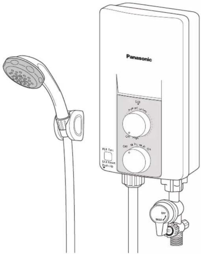
Thank you for purchasing the Panasonic Electric Home Shower. This appliance is intended for household use only. For optimum performance and safety, please carefully read this Operating Instructions and keep this documentation in a safe place for future reference.
CONTENTS
Page No.
BEFORE USING ELECTRIC HOME SHOWER
2
- SAFETY INSTRUCTIONS 2
- PARTS IDENTIFICATION 4
- ACCESSORIES 4
HOW TO USE ELECTRIC HOME SHOWER
5
- HOW TO USE 5
- WATER FLOW RATE ADJUSTMENT 5
- MAINTENANCE 6
- TROUBLESHOOTING 7
- SPECIFICATIONS 7
HOW TO INSTALL ELECTRIC HOME SHOWER
8
- BEFORE INSTALLATION 8
- HOW TO INSTALL 8
- TEST OPERATION 11
BEFORE USING ELECTRIC HOME SHOWER
1. SAFETY INSTRUCTIONS
SAFETY INSTRUCTIONS
To be followed absolutely
Before operating, please read the following "Safety Instructions" carefully.
To prevent personal injury, injury to others and property damage, the following instructions must be followed.
Incorrect operation caused by failure to follow instructions will cause harm or damage, the seriousness of which is classified as follow:
WARNING
This sign warns of death or serious injury.
CAUTION
This sign warns of injury to users or damage to property.
The instructions to be followed are classified by the following symbols:

This symbol (with a white background) denotes an action that is PROHIBITED.


This symbol (with a black background) denote action that is COMPULSORY.
WARNING

Stop using the Unit when any abnormality/failure occurs and turn "OFF" the Miniature Circuit Breaker (MCB). (Risk of smoke/fire/electric shock/scalding)
The ELB Reset Lever cannot be reset. Please refer to item no. 3. TEST OPERATION at page 11.
Burnt odor, or smoke is detected during operation.
The Front Plate/Back Plate is deformed or abnormally hot.
- The outlet water temperature become extremely hot and cannot be controlled using the Power Control Knob. Contact your authorized dealer immediately for maintenance/repair.

• The Unit must be earthed.
Improper grounding could cause electric shock.

- Switch off the Miniature Circuit Breaker (MCB) before any service to avoid electric shock hazards.

- In time of lightning / thunder, switch "OFF" the Miniature Circuit Breaker (MCB) in advance to protect the shower Unit against possible damage.

- Inspect on the built-in ELB (once a month) to avoid a hazard to users such as damage to property, serious injury or death. Please refer to item no. 3. TEST OPERATION at page 11.

• Each time shower water is turned 'ON', check the water temperature by hand before showering.

- When the shower is used by someone such as child, old person, sick person and physically handicapped person, the person responsible for their safety is kindly requested to pay attention and check the shower temperature by using hand from time to time.

- Pay attention to the shower temperature when reducing the volume of water. The shower temperature will become very hot if the water flow rate is too low.

- This appliance is not intended for use by persons (including children) with reduced physical, sensory or mental capabilities, or lack of experience and knowledge, unless they have been given supervision or instruction concerning use of the appliance by a person responsible for their safety. Children should be supervised to ensure that they do not play with the appliance.

- If the ELB Reset Lever cannot be reset even if you push it up or if it soon slides down during operation, please do not use the Unit and contact the authorized dealer immediately to avoid a hazard to users such as damage to property, serious injury or death. Never fix the ELB Reset Lever forcibly with tape and such.

- Do not insert finger or other objects into the electric home shower Unit to avoid physical and electric shock hazards.

- Do not replace the Shower Head, Shower Hose or any other parts of the Unit with spare parts other than genuine parts.
Parts for other models will not fit to this model and may cause hazardous condition to user.
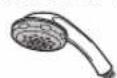

Shower Head Shower Hose

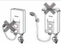
- Do not spray water to the Unit, nor put wet towels on it to avoid from coming into contact with any live parts and such, in order to prevent smoke emission, ignition, fire and electric shock hazards.
CAUTION

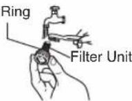
- Please make sure the O Ring is not removed and shall be free from foreign particle to avoid water leaking.
O Ring

- Never use benzene, thinner, bleaching agent and such for cleaning purpose to avoid smoke emission, ignition, fire and electric shock hazards.


- Avoid using dirty water as it may affect heater performance and other components.

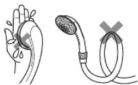
- Do not block the Shower Head with hand, towel or bend the Shower Hose. The water flow rate will drop and water temperature may become very hot.
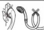

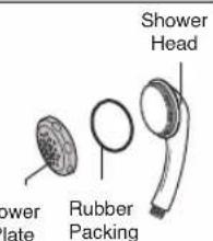
• Take care not to damage the holes of the Shower Plate during the cleaning. The Rubber Packing shall be set on the Shower Head before fixing back the Shower Plate to Shower Head. Do not remove part other than Shower Plate and Rubber Packing.

- In order to avoid a hazard due to inadvertent resetting of the thermal cut-out, this appliance must not be supplied through an external switching device, such as a timer, or connected to a circuit that is regularly switched on and off by the utility.
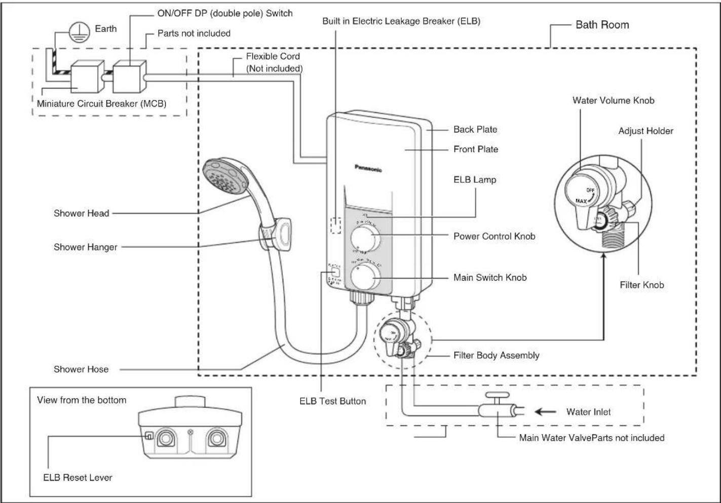
2. PARTS IDENTIFICATION
3. ACCESSORIES
| Description: | Items: | ||
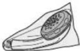 Shower Head Packing Shower Head Packing | 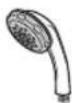 Shower Head (1 set) Shower Head (1 set) | ||
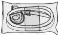 Shower Hanger Packing Shower Hanger Packing | 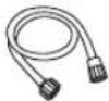 Shower Hose (1 set) Shower Hose (1 set) |  Shower Hanger (1 set) Shower Hanger (1 set) | |
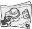 Filter Body Packing Filter Body Packing | 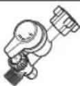 Filter Body Assembly (1 set) Filter Body Assembly (1 set) |  Rubber Packing A (1 pc) Rubber Packing A (1 pc) | 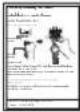 Filter Body Assembly Caution Sheet (1 pc) Filter Body Assembly Caution Sheet (1 pc) |
 Installation Packing Installation Packing | 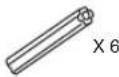 Wall Plug (6 pcs) Wall Plug (6 pcs) |  X 2Rubber Packing A (2 pcs) X 2Rubber Packing A (2 pcs) |  Screws (6 pcs) Screws (6 pcs) |
1. HOW TO USE
- Turn the Water Volume Knob clockwise to turn on the water (make sure the Main Water Valve is on). (Water will flow out from Shower Head at inlet water temperature).
- Switch on the Miniature Circuit Breaker (MCB) and ON/OFF DP (double pole) Switch.
- Push up the ELB Reset Lever if it is down.
- Turn the Main Switch Knob to "On" (ELB Lamp will light).
- The shower temperature can be gradually controlled by turning the Power Control Knob.
If the Power Control Knob is turned clockwise, the shower temperature will increase, reaching the highest temperature at 'High'.
- If the Water Volume Knob is turned clockwise, the volume of water will increase thus the water temperature will decrease.
- If the Water Volume Knob is turned anticlockwise, the volume of water will decrease thus the water temperature will increase. (Please refer WATER FLOW RATE ADJUSTMENT below).
- After using this Unit, please turn off the Main Switch Knob and turn off the water supply by turning the Water Volume Knob anticlockwise until water flow is completely stop.
Note: In case of no water supply, close the Water Volume Knob by turning it anticlockwise and make sure the Main Switch Knob and the Power Control Knob are in "Off" condition (ELB light is off). This is to prevent unnecessary water flow from Shower Head after the water supply recovered.
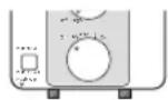
ELB: On condition
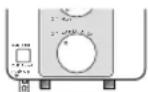
ELB: Off condition

CAUTION

Do not block the Shower Head with hand, towel or bend the Shower Hose. The water flow rate will drop and water temperature may become very hot.
natural_image
Illustration of a hand holding a heart with a pressure drop and a catheter inserted, both without any text or symbols.2. WATER FLOW RATE ADJUSTMENT
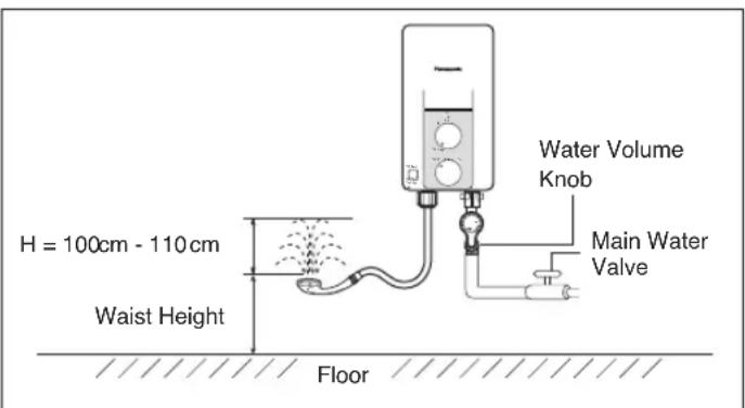
(1) Maximum water flow rate can be adjusted by using Main Water Valve.
Step 1: Turn "OFF" the Main Water Valve.
Step 2: Turn the Shower Head upward at waist height.
Step 3: Turn the Water Volume Knob clockwise to maximum volume position.
Step 4: Gradually turn "ON" the Main Water Valve and adjust the splashing height (H) of the shower.
It is recommended to adjust the water splashing height (H) at 100 cm - 110 cm (approximately 3 L/min).
Note: 1. After setting maximum flow rate, please use Water Volume Knob to turn on and turn off the water supply.
- Pay attention to shower temperature when reducing the volume of water.
The shower temperature will become very hot if the water flow rate is too low.
- In case of continuous usage at high temperature setting, water temperature will increase and the control device will activate temporary resulting the water temperature to drop.
3. MAINTENANCE

WARNING

Switch off the Miniature Circuit Breaker (MCB) before any service to avoid electric shock hazards.
(1) Main Body cleaning.
Be sure to switch "OFF" the Miniature Circuit Breaker (MCB) beforehand.
1) Clean it with moist cloth.
2) Never use benzene, thinner, detergent, bleach and such.
3) Do not spray water to the Unit, nor put wet towels on it.
4) Make sure to use suitable cloth to clean the Front Plate surface to avoid scratch.
(2) Shower Head cleaning.
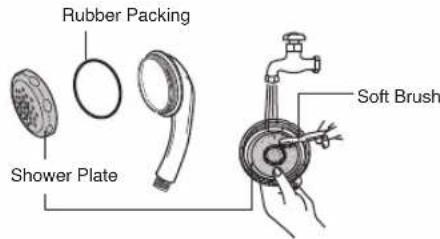
Turn the Shower Plate anticlockwise and remove it from the Shower Head with hand. Clean the Shower Head's holes by using a soft brush from time to time (Recommended once a week).

CAUTION

Take care not to damage the holes of the Shower Head during the cleaning. The Rubber Packing shall be set on the Shower Head before fixing back the Shower Plate to Shower Head. Do not remove other parts other than Shower Plate and Rubber Packing.
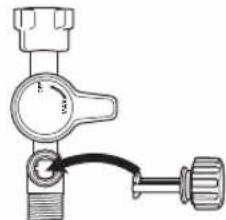
(3) Filter Unit Cleaning (Filter Unit is fixed to Filter Knob)
Clean the Filter of the Filter Unit with water once a week.
Clean the Filter Unit when hot water is not drawn normally.
Dismantle, cleaning and assemble of Filter Unit
① Close the Main Water Valve.
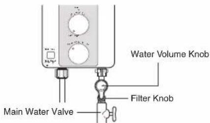
② Turn the Filter Knob anticlockwise and pull it out.
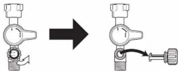
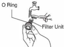
③ Clean the Filter Unit.

CAUTION

Please make sure the O Ring is not removed and shall be free from foreign particle to avoid water leaking.
④ Insert the Filter Unit and tighten it properly (clockwise).
⑤ Turn the Water Volume Knob to its original position based on Water Flow Rate Adjustment at page 5.
natural_image
Mechanical valve assembly diagram with no visible text or symbols4. TROUBLESHOOTING
(1) Check the following points before asking for repair.
| Symptom Points to be checked | |
| Water is not drawn normally. | 1. Check the Filter Unit. Clean the Filter if it is clogged by stain and dirt (refer Filter Unit Cleaning at page 6).2. Check the Shower Head and Shower Plate. Clean the Shower Head and Shower Plate if it is clogged by dirt (refer Shower Head Cleaning at page 6). |
| No hot water comes out from the outlet(no electric supply to the unit) | 1. Make sure the Main Switch Knob is at “On” position.2. Make sure the ELB Reset Lever is not slide down.Push up the ELB Reset Lever to reset the ELB (refer to TEST OPERATION at page 11).3. Make sure to switch on the ON/OFF DP (double pole) Switch.4. Make sure to switch on the Miniature Circuit Breaker (MCB). |
| No water flows out from the Shower Head at all. | 1. Check the Water Volume Knob. Turn the Water Volume Knob clockwise if it is closed.2. Check the Main Water Valve. Turn "ON" the Main Water Valve if it is closed (refer to HOW TO USE at page 5). |
| Water not hot enough. | 1. Check the WATER FLOW RATE ADJUSTMENT as in page 5. |
(2) If abnormalities as mentioned below are found during use, please do not use the Unit and contact your authorized dealer immediately.
1) Water leakage.
2) No water flow.
3) Water temperature cannot be controlled.
4) ELB lamp does not light up.
(3) Special skill is required for repairing. Never try to repair the Unit by yourself.
5. SPECIFICATIONS
| Voltage | 230 V a.c. 60 Hz |
| Power Consumption | 3500 W |
| Electric Power Control | Inlet Water Temp. (Off), 1000 W - 3500 W |
| Min. Water Pressure | 9.8 kPa / 0.1 kgf/cm2 / 1.42 psi |
| Max. Water Pressure | 380 kPa / 3.87 kgf/cm2 / 55 psi |
| Dimension | 295(H) mm X 154(W) mm X 82(D) mm |
| Weight | 1.2 kg |
| Outlet System | Single Point System (Open Outlet) |
HOW TO INSTALL ELECTRIC HOME SHOWER
WARNING

- Proper size of Flexible Cord and electric wiring must be installed to avoid smoke emission and fire hazards.
- During installation process make sure electric and water supply is turn "OFF".
- The home shower must be permanently connected to the electric supply through the ON/OFF DP (double pole) Switch having a contact separation of at least 3 mm in all poles incorporated in the fixed wiring. This switch must be clearly identifiable but out of reach of a person using a fixed bath or shower.

The Unit must be earthed.
Improper grounding could cause electric shock.

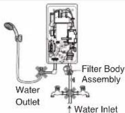
- Never install Filter Body Assembly at the outlet, inlet water cannot be filtered and allows foreign particles to enter the Unit. It will cause Heater Unit and Shower Head to clog up.
- Do not install, remove and reinstall the Unit by yourself. Improper installation will cause leakage, electric shock or fire. Installation and wiring must be done by competent personnel.
- Do not share the inlet and outlet pipe of the Home Shower Unit with other outlets. The pressure may drop due to water being drawn off at other point. The shower temperature may become very hot.
CAUTION

Flexible Cord must enter the Unit thru designated point only (do not make additional holes).
1. BEFORE INSTALLATION
(1) Make sure water flow pressure.
Min. water pressure 9.8 kPa / 0.1 kgf/cm² / 1.42 psi
Max. water pressure 380 kPa / 3.87 kgf/cm² / 55 psi
- How to measure the water pressure as illustrated. Water should flow out of the Hose 2.0 m above the Main Water Valve.
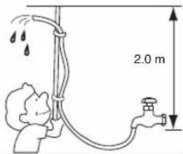
Note: When removing the Unit from package, some water may be found inside. This is normal as the Unit is tested during the manufacturing process.
2. HOW TO INSTALL

WARNING

During installation process make sure electric and water supply is turn "OFF".
-
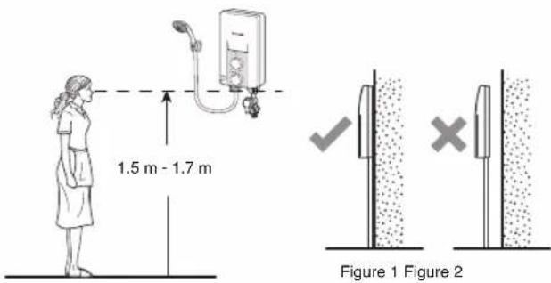
Where to install the Unit.
-
Be sure to install the Unit on the wall as illustrated in Figure 1 (vertical position with the water fittings pointing downward).
- Do not install the Unit away from wall surface as shown in Figure 2.
-
The Unit must be installed at 1.5 m - 1.7 m above the floor.
-
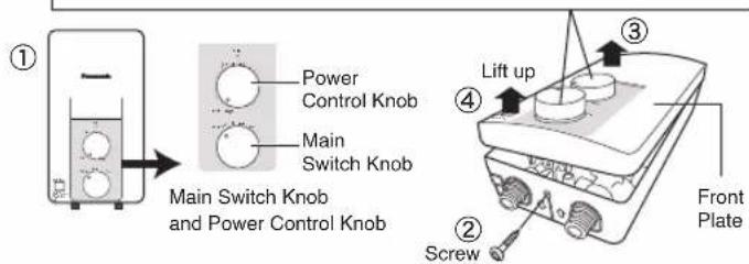
How to remove the Front Plate
① Make sure the Main Switch Knob and Power Control Knob are at "Off" condition.
② Remove the screw at the bottom of the Unit.
③ Lift up the Main Switch Knob to make it free (Main Switch Knob is attached to Rotary Shaft inside the Unit. Do not fully detach the Main Switch Knob from the Front Plate). Make sure the Main Switch Knob and Power Control Knob are not detached from the Front Plate.
④ Remove the Front Plate by lifting up Main Switch Knob and then unhook the top side (Main Switch Knob shall not detach from Front Plate).
Note:
Main Switch Knob and Power Control Knob are attached to Front Plate.
Do not remove Main Switch Knob and Power Control Knob from Front Plate.
3. How to fix Electric Home Shower.
① The distance of the Unit should be more than 250 mm from right and left of the wall.
①
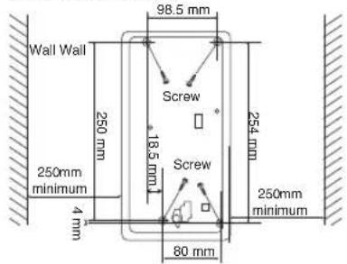
② Make 4 holes at the wall by means of a drill.
③ Drive a Wall Plug into the hole.
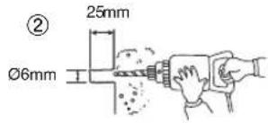
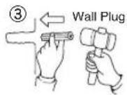
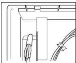
④ Lead the Flexible Cord to the set thru portion as shown below for electric wiring process.
④
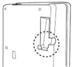
natural_image
Pure mechanical component diagram without any text, numbers, or symbols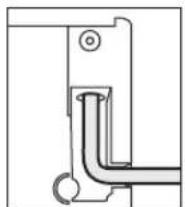
natural_image
Pure electrical circuit lines without any symbolsView from outside View from inside

CAUTION

Flexible Cord must enter the Unit thru designated point only (do not make additional holes).
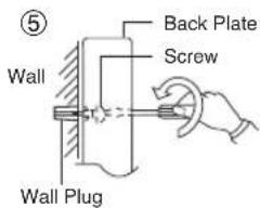
⑤ • Mount the Unit on the wall with 4 screws.
- Drive each Screw into the two upper Wall Plugs through the screw holes on the Back Plate.
• After tighten up the two upper Screws, tighten up the remaining two Screws.
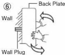
⑥ Please ensure the set fixed tightly on the wall by shaking it left and right.
Note: The Back Plate must be mounted with 4 Screws.
4. Electric wiring

WARNING

Proper size of Flexible Cord and electric wiring must be installed to avoid smoke emission and fire hazards.

WARNING

The home shower must be permanently connected to the electric supply through the ON/OFF DP (double pole) Switch having a contact separation of at least 3 mm in all poles incorporated in the fixed wiring. This switch must be clearly identifiable but out of reach of a person using a fixed bath or shower.
① Lead the Flexible Cord connected to ELB terminal inside the unit: 2.5 mm², 3 core Flexible Cord.
② Unscrew the Cord Holder and fix the Flexible Cord. Strip the lead wire (coating). Fasten the life wire (L) and neutral wire (N) to the ELB (L,N) and earth wire to the Ground Point with 1 N·m (10 kgf.cm) torque. Fix back the Cord Holder to its position to clamp the Flexible Cord.
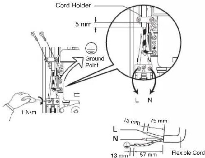
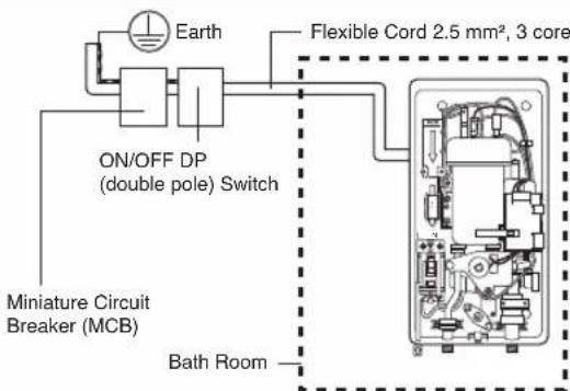
③ Connect wires in correct polarity (L,N).
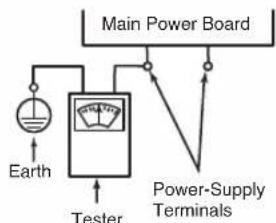
- Connecting the wires in wrong polarity (L,N) causes an abnormal condition which may lead to electric leaking, burning and such.
- Before wiring, please check polarity (L,N) with voltage range of a tester or voltmeter by connecting one terminal of the meter to earth while the other to one of the Power-Supply Terminals. | Main Power
- When the needle of the meter deflects greatly, the polarity of the Power-Supply Terminals is 'L'.
flowchart
graph TD
    A["Earth"] --> B["Main Power Board"]
    B --> C["Tester"]
    C --> D["Power-Supply Terminals"]
    D --> B

WARNING

The Unit must be earthed.
Improper grounding could cause electric shock.
• The Unit must be earthed.
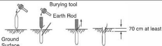
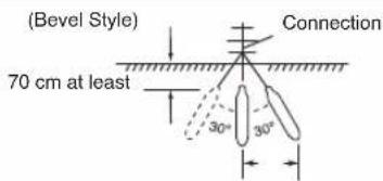
- Earth Rod fixing procedure. Select suitable place to bury the optional Earth Rod (DQ-6H) for at least 70 cm below ground surface.
- Ensure that the ground resistance is less than 100 . If it is not, drive the Earth Rod deeper into ground surface or use 2 or 3 Earth Rods.
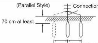
About 2 mAbout 2 m1 m
5. Piping installation procedure
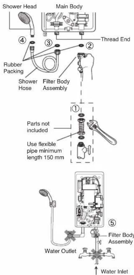
① Place Rubber Packing between Filter Body Assembly and Flexible Pipe. Do not use Piping Tape. Tighten it by Spanner firmly.
② Place Rubber Packing between Filter Body Assembly and Main Body. Do not use Piping Tape. Tighten it by hand firmly.
③ Place Rubber Packing between Shower Hose and Main Body. Do not use Piping Tape. Tighten it by hand firmly.
④ Place Rubber Packing between Shower Hose and Shower Head. Do not use Piping Tape. Tighten it by hand firmly.
⑤ The Filter Body Assembly should be placed in the front direction of the Unit.

WARNING

Do not share the inlet or outlet pipe of Home Shower Unit with other outlets.
The pressure may drop due to water being drawn off at other point. The shower water temperature may become very hot.

CAUTION

Avoid using dirty water as it may affect heater performance and other components.
NOTE:
* Make sure no water leaks from pipe connection.
* When glue is used for external piping connection, must wait for the glue to dry before proceed to test run with water.
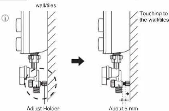
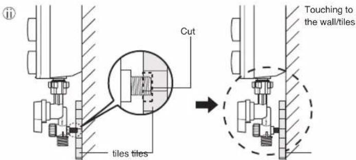
⑥ Adjust Holder Adjustment. (Behind Filter Body Assembly). Set the Adjust Holder behind the Filter Body Assembly by turning it anticlockwise or clockwise. Make sure the Adjust Holder is touching to the wall or tiles.
If the Adjust Holder needs to be cut due to different wall height make sure the Adjust Holder is touching to the wall or tiles to prevent possibility of water leakage at the Filter Body Assembly.
6. How to fix the Front Plate
① Make sure the Main Switch Knob and Power Control Knob on Front Plate and it is at "Off" position.
② Make sure the "D-Cut" position of the Rotary Shaft and VR Shaft are located as shown.
③ Close the Front Plate of the unit according to the sequence as illustrated.
④ Push in the Main Switch Knob and Power Control Knob until it is fully inserted
Note:
1. Do not push the ELB Test Button during fixing the Front Plate. 2. Do not apply extreme force to insert the Main Switch Knob and Power Control Knob during fixing the Front Plate because it will damage the switch inside the Unit. 7. Shower Hanger installation.
Install the Shower Hanger so that the Shower Head top is not higher than the Unit top.   3. TEST OPERATION
1. • Before switch "ON" electricity supply check the wiring. - Switch "ON" the Miniature Circuit Breaker (MCB) and ON/OFF DP (double pole) Switch. - Set the ELB of the Unit to "On". (Push up the ELB Reset Lever if it is down) - Push the ELB Test Button. - It is normal if the ELB turns "Off" (the ELB Reset Lever falls) and push the ELB Reset Lever up. Refer figure as shown. - Inspection on the built-in ELB (once a month) to avoid a hazard to users such as damage to property, serious injury or death. WARNING
 If the ELB Reset Lever cannot be reset even if you push it up or if it soon slides down during operation, please do not use the Unit and contact the authorized dealer immediately to avoid a hazard to users such as damage to property, serious injury or death. Never fix the ELB Reset Lever forcibly with tape and such.  2. · Turn "ON" the Main Water Valve. - Turn the Water Volume Knob clockwise. - Check if water leaks from the Pipe Line. 3. · Turn the Main Switch Knob "On" (ELB lamp will lights). - Turn the Power Control Knob clockwise and hot water will flow out from the Shower Head. (Adjust to suitable water temperature). 4. • Refer detail for HOW TO USE and WATER FLOW RATE ADJUSTMENT on page 5. Panasonic Manufacturing Malaysia Berhad. (196501000304) No. 3, Jalan Sesiku 15/2, Section 15, Shah Alam Industrial Site, 40200 Shah Alam, Selangor Darul Ehsan, Malaysia. http://www.panasonic.com- Operating and Installation Instructions
- Electric Home Shower (Household Use)
- CONTENTS
- BEFORE USING ELECTRIC HOME SHOWER
- HOW TO USE ELECTRIC HOME SHOWER
- HOW TO INSTALL ELECTRIC HOME SHOWER
- SAFETY INSTRUCTIONS
- SAFETY INSTRUCTIONS
- WARNING
- CAUTION
- Stop using the Unit when any abnormality/failure occurs and turn "OFF" the Miniature Circuit Breaker (MCB). (Risk of smoke/fire/electric shock/scalding)
- • The Unit must be earthed.
- PARTS IDENTIFICATION
- ACCESSORIES
- HOW TO USE
- WATER FLOW RATE ADJUSTMENT
- MAINTENANCE
- Main Body cleaning.
- Shower Head cleaning.
- Filter Unit Cleaning (Filter Unit is fixed to Filter Knob)
- Dismantle, cleaning and assemble of Filter Unit
- TROUBLESHOOTING
- SPECIFICATIONS
- The Unit must be earthed.
- BEFORE INSTALLATION
- HOW TO INSTALL
- How to fix Electric Home Shower.
- Electric wiring
- Piping installation procedure
- NOTE:
- How to fix the Front Plate
- Shower Hanger installation.
- TEST OPERATION
Brand : PANASONIC
Model : DH-3PL1
Category : Chauffe-eau instantané et chaudière