
Apollo MS-AP12OOO - Receiver Fusion - Free user manual and instructions
Find the device manual for free Apollo MS-AP12OOO Fusion in PDF.


| Product Type | Marine Monoblock Subwoofer Amplifier |
| Brand | Fusion (a Garmin brand) |
| Model | Apollo MS-AP12OOO |
| Amplifier Class | Class D |
| Peak Power Output | 2000 W |
| RMS Power (4 Ohm, 14.4 Vdc, ≤1% THD+N) | 650 W |
| RMS Power (2 Ohm, 14.4 Vdc, ≤1% THD+N) | 1100 W |
| Frequency Response | 20 Hz – 3.5 kHz (4 Ohm) |
| Input Impedance | 22 kOhm |
| Input Sensitivity (Rated Power, 4 Ohm) | 2.1 Vrms |
| Signal-to-Noise Ratio (Rated Power, 4 Ohm) | 101 dBA |
| Operating Voltage | 10.8 – 16 Vdc |
| Current Draw (Standby) | <5 mA |
| Current Draw (On, No Audio) | 1.15 A |
| Recommended Fuse/Circuit Breaker | 40 A (not included) |
| Remote Turn-On Voltage | >4 Vdc |
| Minimum Speaker Load Impedance | 2 Ohm (4 Ohm nominal) |
| Dimensions (Width x Depth x Height) | 235 x 180 x 45 mm (9.25 x 7.06 x 1.75 in) |
| Weight | 2.2 kg (4 lb 13.6 oz) |
| Water Rating | IEC 60529 IPX2 (drip-proof) |
| Compass-Safe Distance | 75 cm (30 in) |
| Operating Temperature Range | 0 to 50°C (32 to 122°F) |
| Storage Temperature Range | -20 to 70°C (-4 to 158°F) |
| Protection Circuits | Reverse voltage, input under/over voltage, over temperature, output short circuit |
| Mounting Options | Bracket (quick-release) or direct mount with countersunk screws |
| Control/Setup | Requires Fusion-Link app for DSP profile configuration |
| LED Indicator | Single LED bar: Green (operational), Orange (recoverable fault), Red (critical fault) |
| Maintenance | Wipe with a dry cloth; do not use liquids or cleaners |
| Repair/Servicing | No user-serviceable parts. Contact Garmin support or authorized dealer. |
| Compatibility | Only with Fusion DSP-enabled marine audio systems (not for third-party systems) |
Frequently Asked Questions - Apollo MS-AP12OOO Fusion
User questions about Apollo MS-AP12OOO Fusion
0 question about this device. Answer the ones you know or ask your own.
Ask a new question about this device
Download the instructions for your Receiver in PDF format for free! Find your manual Apollo MS-AP12OOO - Fusion and take your electronic device back in hand. On this page are published all the documents necessary for the use of your device. Apollo MS-AP12OOO by Fusion.
USER MANUAL Apollo MS-AP12OOO Fusion
Installation Instructions ......2
Garmin", the Garmin logo, Fusion", Fusion-Link", and the Fusion logo are trademarks of Garmin Ltd. or its subsidiaries, registered in the USA and other countries. These trademarks may not be used without the express permission of Garmin.
M/N: A03876
Fusion® Apollo™ MS-AP12000 Monoblock Amplifier Installation Instructions
Important Safety Information
WARNING
See the Important Safety and Product Information guide in the product box for product warnings and other important information.
This device must be installed according to these instructions.
Disconnect the power supply to the vessel's audio system before beginning to install this device.
CAUTION
Continuous exposure to sound pressure levels over 100 dBA may cause permanent hearing loss. The volume is typically too loud if you cannot hear people speaking around you. Limit the amount of time you listen at high volume. If you experience ringing in your ears or muffled speech, stop listening and have your hearing checked.
To avoid possible personal injury, always wear safety goggles, ear protection, and a dust mask when drilling, cutting, or sanding.
NOTICE
YOU MUST NOT USE THIS AMPLIFIER WITH ANY THIRD-PARTY MARINE
AUDIO SYSTEMS. This amplifier is compatible only with Fusion® DSP-enabled marine audio equipment and may cause damage to third-party speakers due to the amplifier power output.
When drilling or cutting, always check what is on the opposite side of the surface to avoid damaging the vessel.
It is strongly recommended that you have your audio system installed by a professional installer to ensure optimum performance.
You must read all installation instructions before beginning the installation. If you experience difficulty during the installation, go to support.garmin.com for product support.
After installing an audio system, you should run the connected speakers and subwoofers at low to medium volumes during their first few hours of use. This helps to improve the overall sound by gradually loosening up the moving components in the new speakers and subwoofers, such as the cone, spider, and surround. See the installation instructions provided with your speakers, because there may be more details about the recommended low-to-medium volume usage time for each model.
NOTE: After installing the amplifier, you must set up your connected stereo using the Fusion-Link™ app to select and activate the correct DSP profile.
Tools Needed
• 40 A inline fuse or circuit breaker
- Drill and 3 mm ( 1/8 in.) drill bit (or a drill bit appropriate for your provided mounting hardware and mounting-surface material).
- Screwdrivers:
5 mm (7/32 in.) flat (slotted)
4 mm ( 5/32 in.) flat (slotted)
2 Phillips
0 Phillips
- Wire cutter
- Wire stripper
- Wires and cables:
4 AWG (21 through 25 mm 2 ) marine-grade, fully-tinned copper wire for power and ground
NOTE: You may need larger-diameter (smaller gauge number) wire for longer runs to account for voltage drop (Connecting to Power, page 4)
12 AWG (3 through 4 mm 4 ) marine-grade, fully-tinned copper wire for speakers
You can purchase this wire from your Fusion or Garmin ® dealer.
010-12898-00: 7.62 m (25 ft.)
NOTE: You may need larger-diameter (smaller gauge number) wire for longer runs of speaker wire.
20 AWG (0.5 through 0.75 mm 4 ) marine-grade, fully-tinned copper wire for the remote-on signal
- 1-channel RCA cable (Signal and Speaker Connection Considerations, page 5)
You can purchase suitable lengths of RCA cable from the Garmin website at garmin.com/apollo_amplifier_accessories or from your Fusion or Garmin dealer.
- Cable ties (optional)
Mounting Considerations
CAUTION
In high ambient temperatures and after extended use, the device enclosure may reach temperatures deemed dangerous to touch. To avoid possible personal injury, the device must be installed in a location where it will not be touched during operation.
NOTICE
This device should be mounted in a well-ventilated location that is not exposed to extreme temperatures or conditions. The temperature range for this device is listed in the product specifications. Extended exposure to temperatures exceeding the specified temperature range, in storage or operating conditions, may cause device failure. Extreme-temperature-induced damage and related consequences are not covered by the warranty.
This device is designed for installation only in a dry location. Installing this device in a location where it may come in contact with more than occasional dripping water or become submerged may result in damage. Water damage is not covered by the warranty.
You must not mount this device upside-down on the underside of a horizontal mounting surface. Mounting the device in an upside-down orientation reduces the effectiveness of heat dissipation, and may lead to shutdown due to thermal protection.
If you are mounting the device on fiberglass, when drilling the pilot holes, use a countersink bit to drill a clearance counterbore through only the top gel-coat layer. This will help to avoid cracking in the gel-coat layer when the screws are tightened.
You can mount this amplifier using one of two methods:
- You can use the included bracket and pan head screws to mount the amplifier (Installing the Mounting Bracket, page 3).
- Mounting the amplifier using the bracket allows you to quickly attach and detach the amplifier from the mounting surface.
- Mounting the amplifier using the bracket requires clear space above the mounting location to allow for connecting the amplifier to the bracket and installing the locking wedge.
- You can use the included flat-head, countersunk screws to mount the amplifier directly to the mounting surface (Mounting the Device Directly to the Surface, page 4).
- Mounting the amplifier directly to the surface does not allow you to quickly detach the amplifier.
- Mounting the amplifier directly to the surface does not require as much clear space above the mounting location, so it may be a more suitable choice for installing in a smaller space.
When selecting a mounting location, observe these considerations:
- You must mount the amplifier in a location that does not interfere with the fuel tank or electrical wiring.
- You must mount the amplifier in a location where it is not exposed to water.
- You must mount the amplifier in a location where it is not exposed to fuel or fuel vapor.
- You must mount the amplifier in a location with adequate ventilation where it is not exposed to extreme temperatures.
- If you mount amplifier in an enclosed space, you should install a cooling fan with appropriate ducts to aid in airflow.
- You should mount the amplifier so that the cables can be connected easily.
- You must not mount the amplifier upside-down on the underside of a horizontal mounting surface.
• To avoid interference with a magnetic compass, you should mount the amplifier the specified distance away from a compass. This distance is listed in the specifications section.
- You must not mount the amplifier in close proximity to other navigation-critical equipment, antennas, or radio-communication equipment on the vessel.
Installing the Mounting Bracket
NOTICE
Pan-head screws are included, but they may not be suitable for the mounting surface. If you provide different mounting hardware, you must not use fasteners with a countersunk head. Hardware with a countersunk head will damage the mounting bracket.
Before you install the mounting bracket, you must select a mounting location and determine what screws and other mounting hardware are needed for the surface.
Mounting the device using the mounting bracket allows you to quickly attach and remove the device as needed.
1 Use the included template to verify that the mounting location has sufficient clearance to install the device.

natural_image
Mechanical assembly diagram showing a mounted component with mounting holes and a cable (no text or symbols visible)NOTE: You must install the bracket with the release tab pointing up to properly secure the amplifier in the bracket.
2 Using a 3 mm ( 1/8 in.) bit or a bit appropriate for your provided hardware and mounting-surface material, drill the pilot holes marked on the template.
NOTICE
If you are mounting the device on fiberglass, when drilling the pilot holes, use a countersink bit to drill a clearance counterbore through only the top gel-coat layer. This will help to avoid cracking in the gel-coat layer when the screws are tightened.
3 Using the included pan-head screws or other pan-head mounting hardware, secure the bracket to the mounting surface.
NOTICE
You must use pan-head screws, because countersunk screws will damage the bracket.
Connecting the Device to the Mounting Bracket
You must secure the mounting bracket to the surface before you can connect the device.
1 Hold the device over and slightly above the mounting bracket.

2 Place the device onto the bracket ① and pull down ② until the tab audibly clicks.
3 Insert the wedge over the tab on the top of the mounting bracket it and push down to lock the device in the bracket.

natural_image
3D diagram of a device with a mounted component and a cable, no visible text or symbols4 Install the included screw covers in the four holes on the top of the amplifier (optional).
Removing the Device from the Mounting Bracket
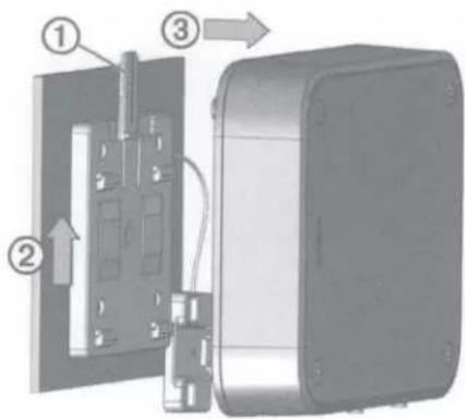
1 Lift up to remove the wedge, which unlocks the tab on the mounting bracket.

natural_image
3D rendering of a mechanical device with an upward arrow and cable, no visible text or symbols2 Press the tab ① on the mounting bracket, and lift up ② on the amplifier to disconnect it from the mount ③.
Mounting the Device Directly to the Surface
If you are installing the device in a location with limited space, or you do not want to use the bracket, you can mount the device directly to the surface.
NOTE: Countersunk screws are provided to mount the device directly to the surface. If you choose to use your own hardware to mount the device directly to the surface, countersunk heads are recommended.
1 Using the provided template, mark the pilot hole locations for the four mounting holes on the device, observing these considerations:
- Because you are not using the bracket, you do not need to observe the upper clearance line on the template.
- You must observe the lower clearance line on the template so that you have the space needed to make the cable connections.
2 Using a 3 mm ( 1/8 in.) bit or a bit appropriate for your provided hardware and mounting-surface material, drill the pilot holes.
NOTICE
If you are mounting the device on fiberglass, when drilling the pilot holes, use a countersink bit to drill a clearance counterbore through only the top gel-coat layer. This will help to avoid cracking in the gel-coat layer when the screws are tightened.
3 Using the provided countersunk screws, secure the device to the mounting surface.
4 Install the included screw covers in the four holes on the top of the amplifier (optional).
Connection Considerations
NOTICE
You should disconnect the power supply to the audio system before making any connections to the amplifier. Failure to disconnect the audio system may result in damage to the amplifier or audio system.
All terminals and connections must be protected from contact with other conductive materials, such as the vessel chassis and other wires. Improper terminal or wire contact may result in damage to the audio system.
When routing power, speaker, and RCA cables, make sure they are not pinched or crushed. A pinched cable may result in contact with other conductive materials which may damage the audio system.
NOTE: You must connect the amplifier to the AMPLIFIER ON wire from the stereo for the amplifier to turn on and off with the stereo.
When selecting and routing cables, consider the following:
- You should use RCA signal cables that are of the appropriate length to connect the stereo to the amplifier. Avoid using cables that are much longer than needed.
- When routing cables, you should not route RCA cables alongside the power cables. Routing audio cables next to the power cables may introduce interference or unwanted noise in the audio signal.
- When routing cables, protect them from sharp objects. You should use rubber grommets when routing cables through metal panels to protect the cables.
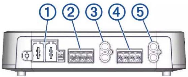
Port Identification

① Power block port (Connecting to Power, page 4)
② Subwoofer speaker block port (Signal and Speaker Connection Considerations, page 5)
③ RCA input port
Connecting to Power
△WARNING
The positive wire (not included) from the power source to the amplifier must run through a 40 A inline fuse or circuit breaker (not included) as close to the power source as possible. Connecting the amplifier to power without an inline fuse or circuit breaker may result in a fire if there is a short in the cable.
You should use 4 AWG (21 through 25 mm 2 ) marine-grade, fully-tinned copper wire (not included) to connect the amplifier to power and ground for most installations. For power-cable runs longer than 5 m (16 ft.), you should consider using larger-diameter (smaller gauge number) wire to minimize power loss.
You must connect the REM terminal on the amplifier block to either the AMPLIFIER ON wire from the connected stereo or to a constant 12 Vdc power source using a switch.
NOTICE
Connecting to the AMPLIFIER ON wire from the stereo instead of using an external switch is recommended to avoid damaging your speakers when the stereo turns on or off.
1 Route 4 AWG (21 through 25 mm 2 ) marine-grade, fully-tinned copper ground wire (not included) to the amplifier and to a ground location on the boat.
2 Using a 5 mm (7/32 in.) flat (slotted) screwdriver, connect the ground wire to the GND terminal on the power connection block.
3 Connect the other end of the ground wire to the ground location.
4 Route 4 AWG (21 through 25 mm 2 ) marine-grade, fully-tinned copper power wire (not included) to the amplifier and to the power source.
5 As close to the power source as possible, install a 40 A inline fuse on the power wire in an accessible location or connect the power wire through a 40 A circuit breaker.
△WARNING
Connecting the amplifier to power without a 40 A inline fuse or circuit breaker may result in a fire if there is a short in the cable.

natural_image
Simple electrical circuit diagram showing a battery connected to a terminal block with a resistor (no text or symbols)6 Using a 5 mm (7/32 in.) flat (slotted) screwdriver, connect the power (+) wire to the PWR terminal on the power connection block.
7 Route a 20 AWG (0.5 through 0.75 mm 4 ) marine-grade, fully-tinned copper remote-on wire (not included) from the amplifier to the AMPLIFIER ON wire on the stereo.
NOTE: The amplifier and the stereo must connect to a common ground terminal point for the AMPLIFIER ON signal to function properly.
8 Using a 4 mm ( 5/32 in.) flat (slotted) screwdriver, connect the remote-on wire to the REM terminal on the power connection block.
NOTICE
You should wait to connect the power terminal block to the amplifier. Make all of the other connections to the stereo and speakers before completing the connection to power (Completing the Connections, page 5).
Signal and Speaker Connection Considerations
When connecting your stereo and subwoofer to the amplifier, observe the following considerations:
- A subwoofer connects to the amplifier using a terminal block (Connecting a Subwoofer to the Amplifier, page 5).
• The amplifier supports a nominal 4 Ohm speaker load impedance, and a 2 Ohm minimum speaker load impedance. - When connecting a subwoofer, you should use 12 AWG (3 through 4mm2 ) marine-grade, fully-tinned copper wire.
- You must connect a 1-channel RCA cable from the subwoofer line out port on the stereo to the single-RCA input port on the amplifier.
Connecting a Subwoofer to the Amplifier
1 Route12 AWG (3 through 4 mm 2 ) marine-grade, fully-tinned copper wire to the subwoofer and the amplifier.
NOTE: You should label both ends of the speaker wire, including polarity, so you can easily identify which wires route to which subwoofer.
2 Connect the speaker wire to the subwoofer, observing polarity.
NOTE: Incorrectly connecting the speaker wire by crossing the polarity may result in poor sound quality.
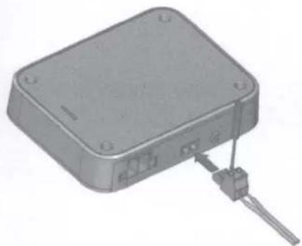
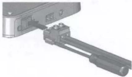
3 Using a 4 mm ( 5/32 in.) flat (slotted) screwdriver, connect the speaker wires to the speaker terminal block.
NOTE: The speaker terminal block is not labeled. Refer to the label on the amplifier port when determining polarity.
natural_image
3D rendering of a rectangular electronic device with a connector and cable inserted (no visible text or symbols)4 When both speaker wires are connected to the terminal block, press the assembled terminal block into the port on the amplifier to complete the subwoofer connection.
5 Connect a 1-channel RCA cable to the RCA subwoofer line-out connector from the stereo for a zone you want to use with the subwoofer.
6 Connect the other end of the 1-channel RCA cable to the single RCA input port on the amplifier.
Completing the Connections
Before you connect the amplifier to the power source, you should complete all other connections to the amplifier.
1 Make sure the speaker wire is connected between the subwoofer and the amplifier, using a speaker terminal block.
2 Make sure the RCA cable is connected between the stereo and the amplifier.
3 Make sure the power and ground cables are connected to the power terminal block and the power source (Connecting to Power, page 4).
4 Make sure the amplifier remote-on wire is connected to the power terminal block and to the amplifier turn-on wire from the stereo (Connecting to Power, page 4).
5 Insert the assembled power terminal block into the power port on the left side of the amplifier.
natural_image
Mechanical assembly diagram showing a shaft and housing component (no text or symbols visible)6 Using a 5 mm ( 7/32 in.) flat (slotted) screwdriver, secure the power terminal block to the amplifier.
NOTICE
After you have completed all connections, you must configure the DSP profile for the amplifier before playing music. If the DSP profile is not set up, you may damage the connected speakers (Configuring the Amplifier, page 5).
Configuring the Amplifier
To configure the amplifier for use with your audio system, you must use the Fusion-Link app to set up the DSP profile after you have completed the connections.
TIP: You can view a video tutorial to help set up a DSP profile for your system at garmin.com/videos/fusion_link_app.
1 Follow the instructions in your stereo owner's manual to download the Fusion-Link app and connect it to the stereo.
2 Select the appropriate amplifier, speakers, and/or subwoofer(s) for each zone in the Fusion-Link app.
3 Follow the instructions in the Fusion-Link app to select a configured profile for the connected amplifier, speakers, and/or subwoofer(s).
4 Send the DSP profile to the connected stereo and test the sound.
5 Repeat steps 3 and 4 until the audio system sounds satisfactory.
Specifications
| Compass-safe distance | 75 cm (30 in.) |
| Operating temperature range | From -0 to 50°C (from 32 to 122°F) |
| Storage temperature range | From -20 to 70°C (from -4 to 158°F) |
| Water rating | IEC 60529 IPX2 1 |
| Maximum wire gauge | Power: 2 AWG (33.63 mm 2 )Speakers: 10 AWG (5.26 mm 2 ) |
| Weight | 2.2 kg (4 lbs 13.6 oz) |
| Amplifier class | Class D |
| Frequency response | 20 Hz to 3.5 kHz (4 Ohm) |
| CEA-2006 power rating @ 14.4 Vdc, 4 Ohm, ≤ 1% THD+N, 50 Hz, AES17-20 kHz BW | 650 W RMS |
| CEA-2006 power rating @ 14.4 Vdc, 2 Ohm, ≤ 1% THD+N, 50 Hz, AES17-20 kHz BW | 1100 W RMS |
| Peak power output | 2000 W |
| Input impedance | 22 kOhm |
| Input sensitivity @ rated power output, 4 Ohm | 2.1 Vrms |
| Signal to noise ratio @ rated power output, 4 Ohm | 101 dBA |
| Signal to noise ratio @ 1 W, 4 Ohm | 75 dBA |
| Operating voltage | 10.8 to 16 Vdc |
| Current draw, standby (@14.4 Vdc input) | less than 5 mA |
| Current draw, on, no audio (@14.4 Vdc input) | 1.15 A |
| Power-cable fuse or circuit breaker rating (not included) | 40 A |
| Remote turn-on | Greater than 4 Vdc |
| Protection circuits | Reverse voltageInput under/over voltageOver temperatureOutput short circuit |
Dimensions


| 1 | 235 mm ( 91/4 in.) |
| 2 | 180 mm ( 71/16 in.) |
| 3 | 45 mm ( 13/4 in.) |
More Information
Troubleshooting
Before you contact your Fusion dealer or service center, you should perform a few simple troubleshooting steps to help diagnose the problem.
If the Fusion amplifier has been installed by a professional installation company, you should contact the company so a technician can assess the problem and advise you about possible solutions.
LED Power Indicator Bar Colors
The single LED power indicator bar on the amplifier changes colors to indicate status and potential faults. You can use these LED color reference tables when troubleshooting the amplifier.
| LED Color | Status |
| Off | Power off |
| Green | Operational |
| Orange | Recoverable fault |
| Red | Critical fault |
LED Is Off
| Potential Cause | Potential Resolution |
| Power connection issue (Connecting to Power, page 4) | Check the power wiring connections to the power terminal block and make sure they are securely connected using the terminal screws.Check the connection between the power terminal block and the amplifier, and make sure the power terminal block is seated securely in the port.Check the power wiring connections to the inline fuse, circuit breaker (if applicable), and battery, and repair or tighten any disconnected or loose wires.Check the inline fuse (if applicable), and replace it if the fuse is blown. If the fuse blows again, disconnect the amplifier from power and contact Garmin Support (support .garmin.com).Check the circuit breaker (if applicable), and reset it if necessary. If the breaker continues to trip, disconnect the amplifier from power and contact Garmin Support (support .garmin.com).If you connected a subwoofer or high-power full-range speakers using the high-power adapter (bridged mode), check the settings in the DSP profile. Using generic or no profile settings with speakers in bridged mode may cause power issues.Make sure the supply voltage is within the specified operating range for the amplifier.Make sure you are using the appropriate gauge for the length of the power cable run, and replace the cable with a thicker gauge, if needed. |
| Remote turn-on wire connection issue | Check the remote turn-on wire connection to the power terminal block and make sure it is securely connected using the terminal screws.Check the remote turn-on wire connection to the stereo and repair or tighten a disconnected or loose wire.Make sure the stereo and the amplifier are connected to a common ground.If you connected the remote turn-on wire to a switch instead of the stereo, make sure the switch is installed correctly. |
LED Is Green and There Is No Sound
| Potential Cause | Potential Resolution |
| Power or volume issue | Make sure the stereo is powered on.Make sure the volume is not set too low or muted.Check the volume limit setting on the stereo. A low limit setting may result in volume issues. |
| DSP settings issue | Check the DSP settings in the Fusion-Link app and make sure the correct speakers and amplifier are selected.NOTE: After you configure the settings, you must select the option in the app to send the DSP settings to the devices. |
| Signal or speaker connection issue | Check the RCA cable connections to the stereo and the amplifier, and re-connect all disconnected cables, if needed.Check the speaker wiring connections to the speaker terminal blocks and make sure they are securely connected using the terminal screws. Reconnect or tighten the wires, if needed.Check the connection between the speaker terminal blocks and the amplifier, and make sure the speaker terminal blocks are seated securely in the ports.Check the wire gauge used to connect the speakers to the amplifier, and make sure it is appropriate for the length of the wire run (Signal and Speaker Connection Considerations, page 5). |
| RCA channel or cable issue | Check the RCA cable for damage and replace it if needed.Check the RCA cable connection to the stereo and make sure it is connected to the intended output.If the RCA cable is connected to the intended output, try connecting it to another zone output from the stereo to determine if there may be an issue with the stereo. |
| Intermittent power issue | Check the power cables to make sure they are the appropriate gauge, are fused, and are connected properly (Connecting to Power, page 4). |
LED Is Green and the Sound Is Not Optimal
| Issue | Potential Resolution |
| There is a hum or other unexpected noise from a speaker | Route the RCA cables away from other cables, especially power cables. Routing RCA cables alongside power cables may introduce interference or unwanted noise in the audio signal.Install ground-loop isolators inline with the RCA cables from the stereo.NOTE: You should install ground-loop isolators on the RCA cables where they connect to the stereo, not where they connect to the amplifier. |
| The sound is distorted or clipping | Check the DSP settings in the Fusion-Link app and make sure the correct amplifier, speakers, and/or subwoofer are selected.NOTE: After you configure the settings, you must select the option in the app to send the DSP settings to the devices. |
| Bass response is reduced or uneven | · Check the polarity of the subwoofer wires and correct it if needed.· Check the DSP settings in the Fusion-Link app and make sure the correct amplifier, speakers, and/or subwoofer are selected.· In the DSP settings, try different phase settings for the subwoofer out to see if it sounds better.NOTE: After you configure the settings, you must select the option in the app to send the DSP settings to the devices. |
LED Is Orange
| Potential Cause | Potential Resolution |
| Power supply under- or over-voltage issue | Check the input power to make sure it is within the 10.8 to 16 Vdc operational range for the amplifier. |
| Power wire gauge issue | Check the wire gauge used to connect the amplifier to power, and make sure it is appropriate for the length of the wire run. |
| Over-temperature issue | Check the temperature of the amplifier and make sure it is under 50°C (122°F). If the amplifier is hotter than the operational temperature rating, add ventilation to the installation location or mount the amplifier in a different location. |
NOTE: The amplifier automatically attempts to recover from a recoverable fault (orange LED). If multiple attempts at recovery are not successful, the amplifier transitions to a critical fault status (red LED). You disconnect the amplifier from the power source for one minute, and then reconnect it or toggle the AMPLIFIER ON signal to reset the critical fault.
LED Is Red
| Potential Cause | Potential Resolution |
| Power wire gauge issue | Check the wire gauge used to connect the amplifier to power, and make sure it is appropriate for the length of the wire run. If you are using high-power full-range speakers or subwoofers, you should consider increasing the power cable gauge (smaller number). |
| Power supply under- or over-voltage issue | Check the input power to make sure it is within the specified voltage operating range for the amplifier.If the amplifier experiences a number of under-voltage faults (orange LED) in a short period of time, it considers the issue a critical fault and changes the LED color to red. A series of orange indicators followed by a red indicator may indicate an under-voltage issue. |
| Prolonged over-temperature issue | Check the temperature of the amplifier and make sure it is under 50°C (122°F). If the amplifier is hotter than the operational temperature rating, add ventilation to the installation location or mount the amplifier in a different location. |
| DSP setting or volume issue | Check the DSP settings in the Fusion-Link app and make sure the correct amplifier, speakers, and/or subwoofers are selected.NOTE: After you configure the settings, you must select the option in the app to send the DSP settings to the stereo. |
| Speaker fault | Check all of the connected speaker wires.Make sure the speaker wires are connected to the speaker terminal blocks and to the speakers properly.Make sure there are no shorts in the speaker wires, and there are no cuts in the speaker-wire jackets that may result in a short. |
| Internal amplifier or power supply fault | Disconnect the amplifier from the power source for one minute, and then reconnect it and test for proper operation. If the LED continues to show a red fault, contact Garmin Support (support.garmin.com). |
物質宣言
See the Important Safety and Product Information guide in the product box for product warnings and other important information.
This device must be installed according to these instructions.
Disconnect the power supply to the vessel's audio system before beginning to install this device.
CAUTION
Continuous exposure to sound pressure levels over 100 dBA may cause permanent hearing loss. The volume is typically too loud if you cannot hear people speaking around you. Limit the amount of time you listen at high volume. If you experience ringing in your ears or muffled speech, stop listening and have your hearing checked.
To avoid possible personal injury, always wear safety goggles, ear protection, and a dust mask when drilling, cutting, or sanding.
NOTICE
YOU MUST NOT USE THIS AMPLIFIER WITH ANY THIRD-PARTY MARINE AUDIO SYSTEMS. This amplifier is compatible only with Fusion DSP-enabled marine audio equipment and may cause damage to third-party speakers due to the amplifier power output.
When drilling or cutting, always check what is on the opposite side of the surface to avoid damaging the vessel.
It is strongly recommended that you have your audio system installed by a professional installer to ensure optimum performance.
You must read all installation instructions before beginning the installation. If you experience difficulty during the installation, go to support.garmin.com for product support.
After installing an audio system, you should run the connected speakers and subwoofers at low to medium volumes during their first few hours of use. This helps to improve the overall sound by gradually loosening up the moving components in the new speakers and subwoofers, such as the cone, spider, and surround. See the installation instructions provided with your speakers, because there may be more details about the recommended low-to-medium volume usage time for each model.
NOTE: After installing the amplifier, you must set up your connected stereo using the Fusion-Link™ app to select and activate the correct DSP profile.
Tools Needed
• 40 A inline fuse or circuit breaker
- Drill and 3mm ( 1/8 in.) drill bit (or a drill bit appropriate for your provided mounting hardware and mounting-surface material).
- Screwdrivers:
- 5 mm (l/32 in.) flat (slotted)
• 4 mm ( 532 in.) flat (slotted) - 3 mm (1/8 in.) flat (slotted)
2 Phillips
0 Phillips
- Wire cutter
- Wire stripper
- Wires and cables:
4 AWG (21 through 25 mm 2 ) marine-grade, fully-tinned copper wire for power and ground
NOTE: You may need larger-diameter (smaller gauge number) wire for longer runs to account for voltage drop (Connecting to Power, page 9)
16 AWG (1.3 through 1.5 mm 2 ) marine-grade, fully-tinned copper wire for standard speakers
You can purchase this wire from your Fusion or Garmin ® dealer:
- 12 AWG (3 through 4mm2 ) marine-grade, fully-tinned copper wire for high-power full-range speakers or subwoofers using the high power adapter (bridged mode)
You can purchase this wire from your Fusion or Garmin dealer:
NOTE: You may need larger-diameter (smaller gauge number) wire for longer runs of speaker or subwoofer wire.
20 AWG (0.5 through 0.75 mm 2 ) marine-grade, fully-tinned copper wire for the remote-on signal
• 2-channel RCA cable (1 per stereo channel pair) (Signal and Speaker Connection Considerations, page 10)
• 1-channel RCA cable (1 per mono channel) (Signal and Speaker Connection Considerations, page 10)
You can purchase a suitable length of RCA cable at garmin.com/apollo_amplifier_accessories or from your Fusion or Garmin dealer.
- Cable ties (optional)
Mounting Considerations
CAUTION
In high ambient temperatures and after extended use, the device enclosure may reach temperatures deemed dangerous to touch. To avoid possible personal injury, the device must be installed in a location where it will not be touched during operation.
NOTICE
This device should be mounted in a well-ventilated location that is not exposed to extreme temperatures or conditions. The temperature range for this device is listed in the product specifications. Extended exposure to temperatures exceeding the specified temperature range, in storage or operating conditions, may cause device failure. Extreme-temperature-induced damage and related consequences are not covered by the warranty.
This device is designed for installation only in a dry location. Installing this device in a location where it may come in contact with more than occasional dripping water or become submerged may result in damage. Water damage is not covered by the warranty.
You must not mount this device upside-down on the underside of a horizontal mounting surface. Mounting the device in an upside-down orientation reduces the effectiveness of heat dissipation, and may lead to shutdown due to thermal protection.
If you are mounting the device on fiberglass, when drilling the pilot holes, use a countersink bit to drill a clearance counterbore through only the top gel-coat layer. This will help to avoid cracking in the gel-coat layer when the screws are tightened.
You can mount this amplifier using one of two methods:
- You can use the included bracket and pan head screws to mount the amplifier (Installing the Mounting Bracket, page 4).
- Mounting the amplifier using the bracket allows you to quickly attach and detach the amplifier from the mounting surface.
-
Mounting the amplifier using the bracket requires clear space above the mounting location to allow for connecting the amplifier to the bracket and installing the locking wedge.
-
You can use the included flat-head, countersunk screws to mount the amplifier directly to the mounting surface (Mounting the Device Directly to the Surface, page 7).
- Mounting the amplifier directly to the surface does not allow you to quickly detach the amplifier.
- Mounting the amplifier directly to the surface does not require as much clear space above the mounting location, so it may be a more suitable choice for installing in a smaller space.
When selecting a mounting location, observe these considerations:
- You must mount the amplifier in a location that does not interfere with the fuel tank or electrical wiring.
- You must mount the amplifier in a location where it is not exposed to water.
- You must mount the amplifier in a location where it is not exposed to fuel or fuel vapor.
- You must mount the amplifier in a location with adequate ventilation where it is not exposed to extreme temperatures.
- If you mount amplifier in an enclosed space, you should install a cooling fan with appropriate ducts to aid in airflow.
- You should mount the amplifier so that the cables can be connected easily.
- You must not mount the amplifier upside-down on the underside of a horizontal mounting surface.
- To avoid interference with a magnetic compass, you should mount the amplifier the specified distance away from a compass. This distance is listed in the specifications section.
- You must not mount the amplifier in close proximity to other navigation-critical equipment, antennas, or radio-communication equipment on the vessel.
Installing the Mounting Bracket
NOTICE
Pan-head screws are included, but they may not be suitable for the mounting surface. If you provide different mounting hardware, you must not use fasteners with a countersunk head. Hardware with a countersunk head will damage the mounting bracket.
Before you install the mounting bracket, you must select a mounting location and determine what screws and other mounting hardware are needed for the surface.
Mounting the device using the mounting bracket allows you to quickly attach and remove the device as needed. 1 Use the included template to verify that the mounting location has sufficient clearance to install the device.

natural_image
3D mechanical assembly diagram showing a mounted device with screws and wires, no visible text or symbolsNOTE: You must install the bracket with the release tab pointing up to properly secure the amplifier in the bracket.
2 Using a 3 mm ( 1/8 in.) bit or a bit appropriate for your provided hardware and mounting-surface material, drill the pilot holes marked on the template.
NOTICE
If you are mounting the device on fiberglass, when drilling the pilot holes, use a countersink bit to drill a clearance counterbore through only the top gel-coat layer. This will help to avoid cracking in the gel-coat layer when the screws are tightened.
3 Using the included pan-head screws or other pan-head mounting hardware, secure the bracket to the mounting surface.
NOTICE
You must use pan-head screws, because countersunk screws will damage the bracket.
Connecting the Device to the Mounting Bracket
You must secure the mounting bracket to the surface before you can connect the device.
1 Hold the device over and slightly above the mounting bracket.

2 Place the device onto the bracket and pull down until the tab audibly clicks.
3 Insert the wedge over the tab on the top of the mounting bracket it and push down to lock the device in the bracket.

natural_image
3D rendering of a mechanical device with a mounted component and mounting base (no text or symbols visible)4 Install the included screw covers in the four holes on the top of the amplifier (optional).
Removing the Device from the Mounting Bracket
1 Lift up to remove the wedge, which unlocks the tab on the mounting bracket.

natural_image
3D rendering of a mechanical device with a mounted component and mounting base (no text or symbols visible)2 Press the tab ① on the mounting bracket, and lift up ② on the amplifier to disconnect it from the mount ③.

Mounting the Device Directly to the Surface
If you are installing the device in a location with limited space, or you do not want to use the bracket, you can mount the device directly to the surface.
NOTE: Countersunk screws are provided to mount the device directly to the surface. If you choose to use your own hardware to mount the device directly to the surface, countersunk heads are recommended.
1 Using the provided template, mark the pilot hole locations for the four mounting holes on the device, observing these considerations:
- Because you are not using the bracket, you do not need to observe the upper clearance line on the template.
- You must observe the lower clearance line on the template so that you have the space needed to make the cable connections.
2 Using a 3mm ( 1/8 in.) bit or a bit appropriate for your provided hardware and mounting-surface material, drill the pilot holes.
NOTICE
If you are mounting the device on fiberglass, when drilling the pilot holes, use a countersink bit to drill a clearance counterbore through only the top gel-coat layer. This will help to avoid cracking in the gel-coat layer when the screws are tightened.
3 Using the provided countersunk screws, secure the device to the mounting surface.
4 Install the included screw covers in the four holes on the top of the amplifier (optional).
Connection Considerations
NOTICE
You should disconnect the power supply to the audio system before making any connections to the amplifier. Failure to disconnect the audio system may result in damage to the amplifier or audio system.
All terminals and connections must be protected from contact with other conductive materials, such as the vessel chassis and other wires. Improper terminal or wire contact may result in damage to the audio system.
When routing power, speaker, and RCA cables, make sure they are not pinched or crushed. A pinched cable may result in contact with other conductive materials which may damage the audio system.
NOTE: You must connect the amplifier to the AMPLIFIER ON wire from the stereo for the amplifier to turn on and off with the stereo.
When selecting and routing cables, consider the following:
- You should use RCA signal cables that are of the appropriate length to connect the stereo to the amplifier. Avoid using cables that are much longer than needed.
- When routing cables, you should not route RCA cables alongside the power cables. Routing audio cables next to the power cables may introduce interference or unwanted noise in the audio signal.
- When routing cables, protect them from sharp objects. You should use rubber grommets when routing cables through metal panels to protect the cables.
Port Identification
MS-AP41200 4-Channel Amplifier

MS-AP61800 6-Channel Amplifier
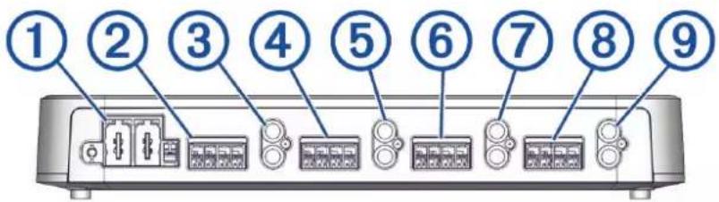
MS-AP82400 8-Channel Amplifier
| 1 | Power block port (Connecting to Power, page 9) |
| 2 | Zone 1 speaker block port (Signal and Speaker Connection Considerations, page 10) |
| 3 | Zone 1 RCA input |
| 4 | Zone 2 speaker block port |
| 5 | Zone 2 RCA input |
| 6 | Zone 3 speaker block port |
| 7 | Zone 3 RCA input |
| 8 | Zone 4 speaker block port |
| 9 | Zone 4 RCA input |
Connecting to Power
WARNING
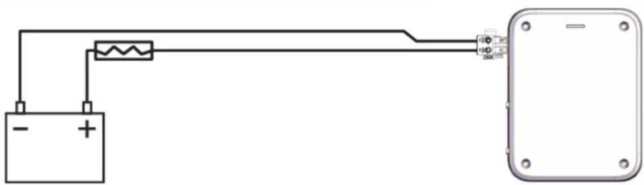
The positive wire (not included) from the power source to the amplifier must run through a 40 A inline fuse or circuit breaker (not included) as close to the power source as possible. Connecting the amplifier to power without an inline fuse or circuit breaker may result in a fire if there is a short in the cable.
You should use 4 AWG (21 through 25 mm 2 ) marine-grade, fully-tinned copper wire (not included) to connect the amplifier to power and ground for most installations. For power-cable runs longer than 5 m (16 ft.), you should consider using larger-diameter (smaller gauge number) wire to minimize power loss.
You must connect the REM terminal on the amplifier block to either the AMPLIFIER ON wire from the connected stereo or to a constant 12 Vdc power source using a switch.
NOTICE
Connecting to the AMPLIFIER ON wire from the stereo instead of using an external switch is recommended to avoid damaging your speakers when the stereo turns on or off.
1 Route 4 AWG (21 through 25 mm 2 ) marine-grade, fully-tinned copper ground wire (not included) to the amplifier and to a ground location on the boat.
2 Using a 5 mm ( 7/32 in.) flat (slotted) screwdriver, connect the ground wire to the GND terminal on the power connection block.
3 Connect the other end of the ground wire to the ground location.
4 Route 4 AWG (21 through 25 mm 2 ) marine-grade, fully-tinned copper power wire (not included) to the amplifier and to the power source.
5 As close to the power source as possible, install a 40 A inline fuse on the power wire in an accessible location or connect the power wire through a 40 A circuit breaker.

natural_image
3D mechanical assembly diagram showing a shaft and housing component (no text or symbols visible)WARNING
Connecting the amplifier to power without a 40 A inline fuse or circuit breaker may result in a fire if there is a short in the cable.
natural_image
Simple electrical circuit diagram showing a battery connected to a resistor and terminal block (no text or symbols)6 Using a 5 mm ( 7/32 in.) flat (slotted) screwdriver, connect the power (+) wire to the PWR terminal on the power connection block.
7 Route a 20 AWG (0.5 through 0.75 mm 2 ) marine-grade, fully-tinned copper remote-on wire (not included) from the amplifier to the AMPLIFIER ON wire on the stereo.
NOTE: The amplifier and the stereo must connect to a common ground terminal point for the AMPLIFIER ON signal to function properly.
8 Using a 4 mm ( 5/32 in.) flat (slotted) screwdriver, connect the remote-on wire to the REM terminal on the power connection block.
NOTICE
You should wait to connect the power terminal block to the amplifier. Make all of the other connections to the stereo and speakers before completing the connection to power (Completing the Connections, page 13).
Signal and Speaker Connection Considerations
When connecting your stereo and speakers to the amplifier, observe the following considerations:
- All speakers connect to the amplifier using terminal blocks (Connecting Standard Full-Range Speakers to the Amplifier, page 11).
- When connecting standard full-range speakers, you should use 16 AWG (1.3 through 1.5 mm2 ) marine-grade, fully-tinned copper wire.
- When connecting high-power full-range speakers or a subwoofer in bridge mode using the included high power adapter, you should use 12 AWG (3 through 4mm2 ) marine-grade, fully-tinned copper wire (Connecting High-Power Full-Range Speakers or a Subwoofer to the Amplifier, page 12).
• Each set of zone speaker terminals on the amplifier is paired to the RCA inputs for that zone.
• Each channel supports a nominal 4 Ohm speaker load impedance, and a 2 Ohm minimum speaker load impedance. - You can connect either a zone line out or a subwoofer line out from the stereo to any of the zone RCA inputs on the amplifier.
- You should observe the zone and polarity markings for each channel when connecting speakers to the amplifier. The speaker ports for each zone are marked with negative (-) and positive (+) for the left (L) and right (R) channels. When connecting a high-power full-range speaker or a subwoofer in bridge mode, the speaker terminal polarity is marked on the high power adapter.
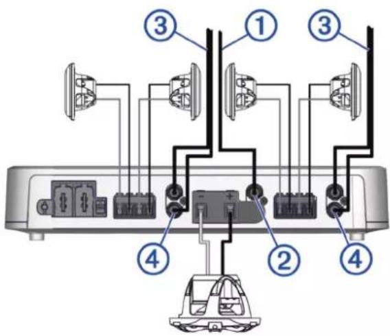
In the following example, a single 4 Ohm subwoofer is connected to ZONE 2 using the high power adapter, and pairs of 4 Ohm standard full-range speakers are connected to the right and left channels for the other two zones.
In this example, you must connect the single RCA subwoofer line out connector from the stereo ① to the uncovered L RCA port for ZONE 2 on the amplifier ② and you must connect the two RCA zone line out connectors from the stereo ③ to the other two zone RCA ports on the amplifier . ④
Connecting Standard Full-Range Speakers to the Amplifier
You must use the provided terminal blocks to connect standard full-range speakers to the amplifier.
1 Route 16 AWG (1.3 through 1.5 mm 2 ) marine-grade, fully-tinned copper speaker wire (not included) to the speakers and the amplifier.
NOTE: You should label both ends of the speaker, including polarity, so you can easily identify which wires route to which speakers.
2 Connect the speaker wire to the speakers, observing polarity.
NOTE: Incorrectly connecting the speaker wire by crossing the polarity may result in poor sound quality.
3 Using a #0 Phillips or a 3 mm ( 1/8 in.) flat (slotted) screwdriver, connect the speaker wires to the speaker terminal blocks, observing the polarity.
NOTE: The speaker terminal blocks are not labeled. Refer to the labels on the amplifier ports when determining polarity.

natural_image
3D rendering of a device housing with an attached sensor module (no text or symbols visible)4 When all speaker wires are connected to the terminal block, press the assembled terminal block into the appropriate ZONE port on the amplifier to complete the speaker connection for the zone.
5 Use a 2-channel RCA cable (not included) to connect the RCA zone line out connectors from the stereo to the RCA input ports for the appropriate zone on the amplifier (Signal and Speaker Connection Considerations, page 10).
6 Repeat this procedure for all of the speakers you want to connect to the amplifier.
Connecting High-Power Full-Range Speakers or a Subwoofer to the Amplifier
NOTICE
The provided high power adapter places two adjacent channels into bridged mode. You should connect only one 4 Ohm high-power full-range speaker or subwoofer to the amplifier when using the high power adapter. Connecting a load of less than 4 Ohm when using the high power adapter may cause damage to the amplifier, speakers, or subwoofers.
You must install the provided high power adapter on the speaker terminal block when connecting a high-power full-range speaker or subwoofer to a zone. This adapter guarantees that the correct speaker terminals are connected and it signals to the amplifier that the zone is operating in high-power mode (commonly referred to as bridged mode). If needed, you can purchase additional adapters from your Fusion dealer.
1 Place the high power adapter over an empty speaker terminal block and press until it clicks in place.
2 Route 12 AWG (3 through 4 mm 2 ) marine-grade, fully-tinned copper speaker wire (not included) to the high-power full-range speaker or subwoofer and the amplifier.
NOTE: You should label both ends of the speaker wire, including polarity, so you can easily identify which wires route to which speakers.
3 Connect the speaker wire to the full-range speaker or subwoofer, observing polarity.

natural_image
Mechanical assembly diagram showing a rotating component with orange arrows indicating motion (no text or symbols)NOTE: Incorrectly connecting the speaker wire by crossing the polarity may result in poor sound quality.
4 Using a #0 Phillips or a 3 mm ( 1/8 in.) flat (slotted) screwdriver, connect the speaker wires to the speaker terminal blocks, observing the polarity labeled on the high power adapter cover.

natural_image
3D rendering of a gray electronic device with ports and a small mechanical component inserted (no text or symbols visible)5 When both speaker wires are connected to the terminal block using the high power adapter, insert the assembled terminal block into the appropriate ZONE port on the amplifier to complete the connection for the zone.
6 Complete an action:
- If you are connecting a subwoofer, connect a 1-channel RCA cable (not included) to the RCA subwoofer line-out connector from the stereo for a zone you want to use with the subwoofer.
- If you are connecting high-power full-range speakers, connect a 2-channel RCA cable (not included) to the RCA zone out connector from the stereo for a zone you want to use with the high-power full-range speakers.
7 Connect the other end of the RCA cable from the stereo to the open RCA input port ① for the channel powering the subwoofer or the channels powering the high-power full-range speakers.
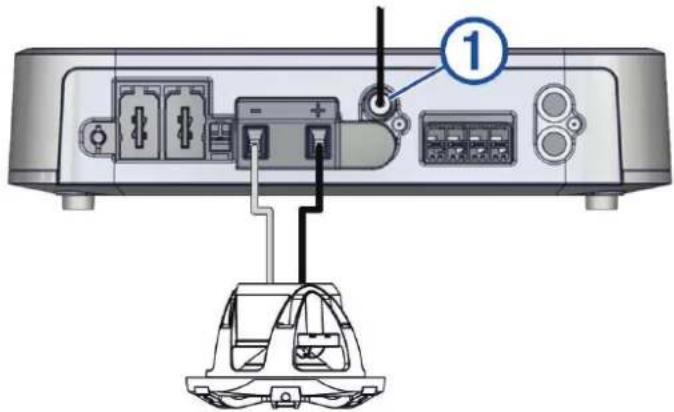
NOTE: Each high-power full-range speaker connects to only one channel from the 2-channel RCA cable from the stereo. Be sure to connect the left RCA channel connector to the RCA port on the amplifier for the channel powering the left high-power full-range speaker, and to connect the right RCA channel connector to the RCA port on the amplifier for the channel powering the right high-power speaker.
8 Repeat this procedure for additional high-power full-range speakers or additional subwoofers.
Completing the Connections
Before you connect the amplifier to the power source, you should complete all other connections to the amplifier.
1 Make sure all speaker wires are connected between the speakers and/or subwoofer(s) and the amplifier, using speaker terminal blocks.
2 Make sure all RCA cables are connected between the stereo and the amplifier.
3 Make sure the power and ground cables are connected to the power terminal block and the power source (Connecting to Power, page 9).
4 Make sure the amplifier remote-on wire is connected to the power terminal block and to the amplifier turn-on wire from the stereo (Connecting to Power, page 9).
5 Insert the assembled power terminal block into the power port on the left side of the amplifier.

natural_image
3D mechanical assembly showing a device with a highlighted internal component and a lever handle (no text or symbols visible)6 Using a 5 mm ( 7/32 in.) flat (slotted) screwdriver, secure the power terminal block to the amplifier.
NOTICE
After you have completed all connections, you must configure the DSP profile for the amplifier before playing music. If the DSP profile is not set up, you may damage the connected speakers (Configuring the Amplifier, page 14).
Configuring the Amplifier
To configure the amplifier for use with your stereo and speakers, you must use the Fusion-Link app to set up the DSP profile after you have completed the connections.
TIP: You can view a video tutorial to help set up a DSP profile for your system at garmin.com/videos/fusion_link_app.
1 Follow the instructions in your stereo owner's manual to download the Fusion-Link app and connect it to the stereo.
2 Select the appropriate amplifier, speakers, and/or subwoofer(s) for each zone in the Fusion-Link app.
3 Follow the instructions in the Fusion-Link app to select a configured profile for the connected amplifier, speakers, and/or subwoofer(s).
4 Send the DSP profile to the connected stereo and test the sound.
5 Repeat steps 3 and 4 until the audio system sounds satisfactory.
Specifications
| Compass-safe distance | MS-AP41200: 75 cm (30 in.)MS-AP61800: 145 cm (57 in.)MS-AP82400: 245 cm ( 961/2 in.) |
| Operating temperature range From 0 to 50°C (from 32 to 122°F) | |
| Storage temperature range From -20 to 70°C (from -4 to 158°F) | |
| Water rating IEC 60529 IPX2 | 1 |
| Maximum wire gauge | Power: 2 AWG ( 33.63 mm2 )Speakers: 12 AWG ( 3.31 mm2 ) |
| Weight | MS-AP41200: 2.2 kg (4 lbs 13.6 oz)MS-AP61800: 2.7 kg (5 lbs 15.2 oz)MS-AP82400: 3.15 kg (6 lbs 15.1 oz) |
| Amplifier class Class D | |
| Frequency response 20 Hz to 20 kHz | |
| CEA-2006 power rating per channel @ 14.4 Vdc, 4 Ohm, ≤ 1% THD+N, 1 kHz, AES17-20 kHz BW | 150 W RMS per channel |
| CEA-2006 power rating per channel @ 14.4 Vdc, 2 Ohm, ≤ 1% THD+N, 1 kHz, AES17-20 kHz BW | 290 W RMS per channel |
| CEA-2006 power rating per channel @ 14.4 Vdc, 4 Ohm bridged, ≤ 1% THD+N, 1 kHz, AES17-20 kHz BW2 | 580 W RMS per channel |
| Peak power output | MS-AP41200: 1200 WMS-AP61800: 1800 WMS-AP82400: 2400 W |
| Input impedance 22 kOhm | |
| Input sensitivity @ rated power output, 4 Ohm 1.6 Vrms | |
| Signal to noise ratio @ rated power output, 4 Ohm All models: 97 dBA | |
| Signal to noise ratio @ 1 W, 4 Ohm All models: 75 dBA | |
| Separation/crosstalk | MS-AP41200: 61 dBMS-AP61800: 58 dBMS-AP82400: 58 dB |
| Operating voltage 10.8 to 16 Vdc | |
| Current draw, in standby/off using AMPLIFIER ON wire (@14.4 Vdc input) | less than 5 mA |
| Current draw, on, no audio (@14.4 Vdc input) | MS-AP41200: 1.15 AMS-AP61800: 1.32 AMS-AP82400: 1.6 A |
| Power-cable fuse or circuit breaker rating (not included) 40 A | |
| Remote turn-on Greater than 4 Vdc | |
Protection circuits
Reverse voltage
Input under/over voltage
Over temperature
Output short circuit
Dimensions

NOTE: A MS-AP41200 amplifier is shown for illustration purposes. Refer to the table for model-specific measurements.
| 1 | MS-AP41200: 235 mm ( 91/4 in.)MS-AP61800: 297 mm ( 1111/16 in.)MS-AP82400: 359 mm ( 141/8 in.) |
| 2 | 180 mm ( 71/16 in.) |
| 3 | 45 mm ( 13/4 in.) |
More Information
Troubleshooting
Before you contact your Fusion dealer or service center, you should perform a few simple troubleshooting steps to help diagnose the problem.
If the Fusion amplifier has been installed by a professional installation company, you should contact the company so a technician can assess the problem and advise you about possible solutions.
LED Power Indicator Bar Colors
The single LED power indicator bar on the amplifier changes colors to indicate status and potential faults. You can use these LED color reference tables when troubleshooting the amplifier.
| LED Color Status | |
| Off Power off | |
| Green Operational | |
| Orange Recoverable fault | |
| Red Critical fault | |
LED Is Off
| Potential Cause Potential Resolution | |
| Power connection issue (Connecting to Power, page 9) | ·Check the power wiring connections to the power terminal block and make sure they are securely connected using the terminal screws.·Check the connection between the power terminal block and the amplifier, and make sure the power terminal block is seated securely in the port.·Check the power wiring connections to the inline fuse, circuit breaker (if applicable), and battery, and repair or tighten any disconnected or loose wires.·Check the inline fuse (if applicable), and replace it if the fuse is blown. If the fuse blows again, disconnect the amplifier from power and contact Garmin Support (support.garmin.com).·Check the circuit breaker (if applicable), and reset it if necessary. If the breaker continues to trip, disconnect the amplifier from power and contact Garmin Support (support.garmin.com).·If you connected a subwoofer or high-power full-range speakers using the high-power adapter (bridged mode), check the settings in the DSP profile. Using generic or no profile settings with speakers in bridged mode may cause power issues.·Make sure the supply voltage is within the specified operating range for the amplifier.·Make sure you are using the appropriate gauge for the length of the power cable run, and replace the cable with a thicker gauge, if needed. |
| Remote turn-on wire connection issue | ·Check the remote turn-on wire connection to the power terminal block and make sure it is securely connected using the terminal screws.·Check the remote turn-on wire connection to the stereo and repair or tighten a disconnected or loose wire.·Make sure the stereo and the amplifier are connected to a common ground.·If you connected the remote turn-on wire to a switch instead of the stereo, make sure the switch is installed correctly. |
LED Is Green and There Is No Sound
| Potential Cause | Potential Resolution |
| Power or volume issue | Make sure the stereo is powered on.Make sure the volume is not set too low or muted.Check the volume limit setting on the stereo. A low limit setting may result in volume issues. |
| DSP settings issue | Check the DSP settings in the Fusion-Link app and make sure the correct speakers and amplifier are selected.NOTE: After you configure the settings, you must select the option in the app to send the DSP settings to the devices. |
| Signal or speaker connection issue | Check the RCA cable connections to the stereo and the amplifier, and re-connect all disconnected cables, if needed.Check the speaker wiring connections to the speaker terminal blocks and make sure they are securely connected using the terminal screws. Reconnect or tighten the wires, if needed.Check the connection between the speaker terminal blocks and the amplifier, and make sure the speaker terminal blocks are seated securely in the ports.Check the wire gauge used to connect the speakers to the amplifier, and make sure it is appropriate for the length of the wire run (Signal and Speaker Connection Considerations, page 10). |
| RCA channel or cable issue | Check the RCA cable for damage and replace it if needed.Check the RCA cable connection to the stereo and make sure it is connected to the intended output.If the RCA cable is connected to the intended output, try connecting it to another zone output from the stereo to determine if there may be an issue with the stereo. |
| Intermittent power issue | Check the power cables to make sure they are the appropriate gauge, are fused, and are connected properly (Connecting to Power, page 9). |
LED Is Green and the Sound Is Not Optimal
| Issue Potential Resolution | |
| There is a hum or other unexpected noise from a speaker | Route the RCA cables away from other cables, especially power cables. Routing RCA cables alongside power cables may introduce interference or unwanted noise in the audio signal.Install ground-loop isolators inline with the RCA cables from the stereo.NOTE: You should install ground-loop isolators on the RCA cables where they connect to the stereo, not where they connect to the amplifier. |
| The sound is distorted or clipping | Check the DSP settings in the Fusion-Link app and make sure the correct amplifier, speakers, and/or subwoofer are selected.NOTE: After you configure the settings, you must select the option in the app to send the DSP settings to the devices. |
| Bass response is reduced or uneven | · Check the polarity of the subwoofer wires and correct it if needed.· Check the DSP settings in the Fusion-Link app and make sure the correct amplifier, speakers, and/or subwoofer are selected.· In the DSP settings, try different phase settings for the subwoofer out to see if it sounds better.NOTE: After you configure the settings, you must select the option in the app to send the DSP settings to the devices. |
LED Is Orange
| Potential Cause Potential Resolution | |
| Power supply under- or over-voltage issue | Check the input power to make sure it is within the 10.8 to 16 Vdc operational range for the amplifier. |
| Power wire gauge issue | Check the wire gauge used to connect the amplifier to power, and make sure it is appropriate for the length of the wire run. |
| Over-temperature issue | Check the temperature of the amplifier and make sure it is under 50°C (122°F). If the amplifier is hotter than the operational temperature rating, add ventilation to the installation location or mount the amplifier in a different location. |
NOTE: The amplifier automatically attempts to recover from a recoverable fault (orange LED). If multiple attempts at recovery are not successful, the amplifier transitions to a critical fault status (red LED). You disconnect the amplifier from the power source for one minute, and then reconnect it or toggle the AMPLIFIER ON signal to reset the critical fault.
LED Is Red
| Potential Cause Potential Resolution | |
| Power wire gauge issue | Check the wire gauge used to connect the amplifier to power, and make sure it is appropriate for the length of the wire run. If you are using high-power full-range speakers or subwoofers, you should consider increasing the power cable gauge (smaller number). |
| Power supply under- or over-voltage issue | Check the input power to make sure it is within the specified voltage operating range for the amplifier.If the amplifier experiences a number of under-voltage faults (orange LED) in a short period of time, it considers the issue a critical fault and changes the LED color to red.A series of orange indicators followed by a red indicator may indicate an under-voltage issue. |
| Prolonged over-temperature issue | Check the temperature of the amplifier and make sure it is under 50°C (122°F). If the amplifier is hotter than the operational temperature rating, add ventilation to the installation location or mount the amplifier in a different location. |
| DSP setting or volume issue | Check the DSP settings in the Fusion-Link app and make sure the correct amplifier, speakers, and/or subwoofers are selected.NOTE: After you configure the settings, you must select the option in the app to send the DSP settings to the stereo. |
| Speaker fault | Check all of the connected speaker wires.Make sure the speaker wires are connected to the speaker terminal blocks and to the speakers properly.Make sure there are no shorts in the speaker wires, and there are no cuts in the speaker-wire jackets that may result in a short. |
| Internal amplifier or power supply fault | Disconnect the amplifier from the power source for one minute, and then reconnect it and test for proper operation. If the LED continues to show a red fault, contact Garmin Support (support.garmin.com). |
物質宣言
© 2023 Garmin Ltd. or its subsidiaries
Garmin 2 , the Garmin logo, Fusion 2 , Fusion-Link ™ , and the Fusion logo are trademarks of Garmin Ltd. or its subsidiaries, registered in the USA and other countries. These trademarks may not be used without the express permission of Garmin.
M/N: A03843 / A03888 / A03889
FUSON®
A Garmin Brand
Apollo™ MS-AP12000
Apollo MS-AP41200
Mounting Template
100 mm (4 in.) clearance required when mounting using the bracket. 25 mm (1 in.) required when mounting the amplifier directly to the surface.
Provide sufficient clearance for the cable bending radius and to allow room for the tool used to secure the power terminal block to the amplifier. Required for both mounting options.
Veillez à laisser un écart suffisant selon le rayon de courbure du câble et pour utiliser les outils qui permettent de fixer le bornier d'alimentation à l'ampli. Requis pour les deux options d'montaggio. Lasciare spazio libero sufficiente per il raggio di curvatura del cavo e per consentire l'uso dello strumento per fissare la morsettiera all'amplificatore. Questo è necessario per entrambe leiten erforderlich.
natural_image
Warning symbol with exclamation mark inside a triangle (no text or numbers)IMPORTANT SAFETY AND PRODUCT INFORMATION
WARNING
Failure to heed the following warnings could result in an accident resulting in death or serious injury.
Marine Operation Warnings
- You are responsible for the safe and prudent operation of your vessel. This device does not relieve you from the responsibility of safely operating your vessel. Avoid navigational hazards and never leave the helm unattended.
• Always be prepared to promptly regain control of the vessel. Use caution near hazards in the water, such as docks, pilings and other vessels.
Hearing Damage Warning
Listening to the stereo at high volume can cause damage to your hearing.
Product Environmental Programs
Information about the Garmin ® product recycling program and WEEE, RoHS, REACH, and other compliance programs can be found at garmin.com/aboutGarmin/environment.
Declaration of Conformity
Hereby, Garmin declares that this product is in compliance with the Directive 2014/53/EU. The full text of the EU declaration of conformity is available at the following internet address: garmin.com/compliance.
UK Declaration of Conformity
Hereby, Garmin declares that this product is in compliance with the relevant statutory requirements. The full text of the declaration of conformity is available at the following internet address: garmin.com/compliance.
FCC Compliance
This device complies with part 15 of the FCC Rules. Operation is subject to the following two conditions: (1) this device may not cause harmful interference, and (2) this device must accept any interference received, including interference that may cause undesired operation.
This equipment has been tested and found to comply with the limits for a Class B digital device, pursuant to part 15 of the FCC rules. These limits are designed to provide reasonable protection against harmful interference in a residential installation. This equipment generates, uses, and can radiate radio frequency energy and may cause harmful interference to radio communications if not installed and used in accordance with the instructions. However, there is no guarantee that interference will not occur in a particular installation. If this equipment does cause harmful interference to radio or television reception, which can be determined by turning the equipment off and on, the user is encouraged to try to correct the interference by one of the following measures:
- Reorient or relocate the receiving antenna.
- Increase the separation between the equipment and the receiver.
- Connect the equipment into an outlet on a circuit different from that to which the receiver is connected.
- Consult the dealer or an experienced radio/TV technician for help.
This product does not contain any user-serviceable parts. Repairs should only be made by an authorized Garmin service center. Unauthorized repairs or modifications could result in permanent damage to the equipment, and void your warranty and your authority to operate this device under Part 15 regulations.
Innovation, Science and Economic Development Canada Compliance
This device contains licence-exempt transmitter(s)/receiver(s) that comply with Innovation, Science and Economic Development Canada's licence-exempt RSS(s). Operation is subject to the following two conditions: (1) this device may not cause interference, and (2) this device must accept any interference, including interference that may cause undesired operation of the device.
Limited 3-Year Marine Consumer Warranty
Garmin New Zealand Limited, trading as Fusion ® Entertainment ('Fusion'), warrants that this Fusion Marine product is free from defects in material and workmanship, according to the following terms and conditions:
- The limited warranty for the Fusion product purchased extends to 36 months beginning on the date of purchase of the product.
- The limited warranty extends only to consumers who purchase the product in one of the countries (or areas) set forth on garmin.com/compliance. The limited warranty is only valid in Fusion's intended country (or area) of sale of the product.
- During the limited warranty period, Fusion or its authorised service network will repair or replace (at Fusion's discretion), any defective product or parts thereof with new and return the product to the consumer in working condition. No charge will be made to the consumer for either parts or labour in repairing or replacing the product. All replaced parts and cosmetic parts should be free of defects at the time of shipment and, therefore shall not be covered under these limited warranty terms.
- Repaired product will be warranted for the balance of the original warranty period or for ninety (90) days from the date of repair, whichever is longer.
- All warranty claims must be accompanied with a copy of this warranty card, and a copy of proof of purchase.
The consumer shall have no coverage or benefits under this limited warranty if any of the following conditions are applicable:
- The product has been subject to: abnormal use, abnormal conditions, improper storage, unauthorised modifications, unauthorised connections, unauthorised repair including but not limited to use of unauthorised spare parts in repairs, misuse, neglect, abuse, accident, alteration, improper installation, acts of God, spill of foods or liquids, maladjustment of customer controls or other acts which are beyond the reasonable control of Fusion, including deficiencies in consumable parts such as fuses, and breakage or damage to antennae unless caused directly by defects in materials or workmanship, and normal wear and tear of the product.
- Fusion was not notified by the consumer of the alleged defect or malfunction of the product during the applicable limited warranty period.
- The product serial number or the accessory date code has been removed, defaced or altered.
- The product was used with or connected to an accessory not supplied by Fusion or fit for use with Fusion product, or used in a manner other than its intended use.
If a problem develops during the limited warranty period, the consumer should take the following step-by-step procedure:
1 The consumer shall return the product to any authorised Fusion dealer in authorised sales countries for repair or replacement processing. Fusion assumes no freight or shipping responsibility for returning goods to an authorised Fusion dealer, or return freight from an authorised dealer to the consumer submitting the warranty claim.
2The consumer shall be charged for any parts or labour charges not covered by this limited warranty. The consumer shall be responsible for expenses related to removal and reinstallation of the product.
3If the product is returned to Fusion after the expiration of the warranty period, Fusion's normal service policies shall apply and the consumer will be charged accordingly.
The benefits conferred by this warranty apply to the extent that they are not superseded by any other rights and remedies available under any applicable legislation that cannot be excluded. In jurisdictions where implied or legal warranties may be excluded, any implied or legal warranty is hereby excluded and the foregoing warranty is the purchaser's sole and exclusive remedy and is in lieu of all other warranties, express or implied.
- Some states in America do not allow the exclusion or limitation of consequential damages, so the above limitation and exclusion may not apply to you. This warranty gives you specific legal rights which may vary from state to state.
- Fusion neither assumes nor authorises any authorised service centre or any person or entity to assume for it any other obligation or liability beyond that which is expressly provided for in this warranty.
- All warranty information, product features and specifications are subject to change without notice.
Limited 3-Year Marine Consumer Warranty for Australian Consumers
Garmin Australasia, 30 Clay Place, Eastern Creek, NSW 2766, Australia.
EMAIL: australia@fusionentertainment.com PHONE: 1800 235 822
THE FUSION PROMISE OF QUALITY LIMITED 3-YEAR CONSUMER WARRANTY
This warranty is given in addition to other rights and remedies available to the consumer under Australian Consumer Law. In addition to the Fusion Warranty, our goods come with guarantees that cannot be excluded under the Australian Consumer Law. You are entitled to a replacement or refund for a major failure and for compensation for any others reasonably foreseeable loss or damage. You are also entitled to have the goods repaired or replaced if the goods fail to be of acceptable quality and the failure does not amount to a major failure.
Garmin New Zealand Limited, trading as Fusion Entertainment ('Fusion'), warrants this Fusion Product including, Speaker, Subwoofer, Amplifier, Head Unit, or genuine Fusion Accessory 'product' is free from defects in materials and workmanship, in accordance with the following terms and conditions:
- The limited warranty for the Fusion product purchased is only available for (36) months after the date of purchase.
- The limited warranty extends only to the original consumer of the product and may not be assigned or transferred to any other person or consumer without Fusion's prior written consent being provided.
- During the limited warranty period, Fusion or its authorised service network will repair or replace any defective or faulty product or parts at its own cost.
- Repaired or replaced product will be warranted for the balance of the original warranty period or for ninety (90) days after the date of repair, whichever is longer.
- All warranty claims must be notified to Fusion or its authorised Dealer in writing during the warranty period accompanied with a copy of this warranty card, proof of purchase date and the product with an intact and unaltered serial number or accessory date code.
This warranty will not apply if:
The consumer causes the Product to be of unacceptable quality or fails to take steps to prevent the product from becoming of unacceptable quality and/or it is damaged by abnormal use. Examples of goods becoming of unacceptable quality or of abnormal use by the consumer include:
- Storage of product under improper conditions.
- Exposure to excessive moisture or dampness.
- Exposure to excessive temperature extremes or other adverse environmental conditions.
- Unauthorised modifications of product, connections or otherwise unauthorised repairs including, but not limited, to the use of unauthorised parts in the repair of products.
- Improper use of or installation of, or interference with, product adjustments or controls and or including antenna breakage or damage due to misuse.
- Damage caused by consumables or by electricity supply.
- Acts of god (force majeure), exposure of product to food spills, or any other type of fluid ingress.
- Using the product in a way for which was not intended to be used or connecting it to an accessory not supplied by, specified by, or authorised by Fusion.
- Any other abnormal use of or conduct causing product to become of unacceptable quality.
Other exclusions:
- This warranty extends to the repair or replacement of Fusion product only and the consumer is responsible for any expenses relating to the removal or installation of the product or related services including the cost of delivering the product to Fusion or its authorised dealer.
-
Repair work conducted by Fusion after this warranty has expired or if this warranty for any other reason this Fusion warranty does not apply is subject to Fusion's normal service policies and Fusion charges for labour and material may apply.
-
This is a manufacturers warranty provided to consumers of Fusion products. Variations to this warranty may only be made by Fusion and will be notified to the customer in writing or issued on the Fusion website. Fusion Dealers, agents and authorised dealers are not authorised to make changes or vary this Fusion warranty.
- All warranty information, product features and specifications are subject to change without notice.
- Fusion is not responsible for replacing or the cost of replacing any consumer data lost occurring either due to equipment failure or during the repair and replacement process.
- This is a manufacturers warranty provided to consumers of Fusion products. Variations to this warranty may only be made by Fusion and will be notified to the customer in writing or issued on the Fusion website. Fusion Dealers, agents and authorised dealers are not authorised to make changes or vary this Fusion warranty.
- All warranty information, product features and specifications are subject to change without notice.
- Fusion is not responsible for replacing or the cost of replacing any consumer data lost occurring either due to equipment failure or during the repair and replacement process.
重要安全和产品信息
警告
© 2020 Garmin Ltd. or its subsidiaries
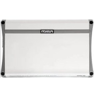
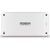
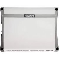

- Fusion® Apollo™ MS-AP12000 Monoblock Amplifier Installation Instructions
- Important Safety Information
- WARNING
- CAUTION
- NOTICE
- YOU MUST NOT USE THIS AMPLIFIER WITH ANY THIRD-PARTY MARINE
- Tools Needed
- Phillips
- Phillips
- Mounting Considerations
- Installing the Mounting Bracket
- Connecting the Device to the Mounting Bracket
- Removing the Device from the Mounting Bracket
- Mounting the Device Directly to the Surface
- Connection Considerations
- Port Identification
- Connecting to Power
- △WARNING
- Signal and Speaker Connection Considerations
- Connecting a Subwoofer to the Amplifier
- Completing the Connections
- Configuring the Amplifier
- More Information
- Troubleshooting
- LED Power Indicator Bar Colors
- Connecting Standard Full-Range Speakers to the Amplifier
- Connecting High-Power Full-Range Speakers or a Subwoofer to the Amplifier
- Dimensions
- FUSON®
- Apollo™ MS-AP12000
- Apollo MS-AP41200
- Mounting Template
- Marine Operation Warnings
- Hearing Damage Warning
- Product Environmental Programs
- Declaration of Conformity
- UK Declaration of Conformity
- FCC Compliance
- Innovation, Science and Economic Development Canada Compliance
- Limited 3-Year Marine Consumer Warranty
- Limited 3-Year Marine Consumer Warranty for Australian Consumers
- THE FUSION PROMISE OF QUALITY LIMITED 3-YEAR CONSUMER WARRANTY
- This warranty will not apply if:
- Other exclusions:
- 重要安全和产品信息
- 警告
Brand : Fusion
Model : Apollo MS-AP12OOO
Category : Receiver