PS-8810 - Uncategorized BSS Audio - Free user manual and instructions
Find the device manual for free PS-8810 BSS Audio in PDF.


| Product Type | Digital Signal Processor with 24x10 matrix mixer and dual input processing paths |
| Brand | BSS Audio |
| Model | PS-8810 (standard) / PS-8810C (with CobraNet) |
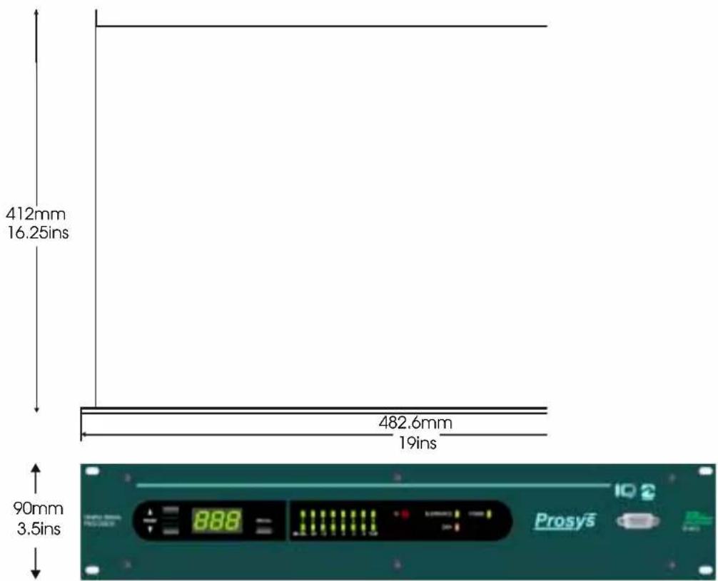
| Form Factor | 19-inch rack mount, 3.5" (2U) height |
| Dimensions (W x D x H) | 19 x 16 x 3.5 inches (48.3 x 40.6 x 8.9 cm) |
| Weight | 13.25 lbs (6.1 kg) |
| Power Supply | 100-240 VAC, 50/60 Hz, 24 W nominal |
| Audio Inputs | 8 balanced analog (mic/line/phantom), 3-pin barrier block; plus 8 digital via CobraNet (PS-8810C) |
| Audio Outputs | 10 balanced analog (2 main + 8 aux), 3-pin barrier block; plus 8 digital via CobraNet (PS-8810C) |
| Digital Audio Conversion | 24-bit, 48 kHz sampling |
| DSP Processing Power | 240 MIPS, 4 SHARC processors, approx. 4000 DSP objects |
| Input Processing per Channel | Fader, mute, polarity, gate, compressor, auto-leveler, 2 filter sections (up to 256 filters total), delay (up to 2 s) |
| Output Processing per Channel | Delay, 2 filter sections, ambient leveler, output limiter |
| Automixing | NOM attenuation, priority ducking, adaptive gating, up to 32 automix groups |
| Matrix Mixer | 24 x 10 crosspoint (with CobraNet) / 16 x 10 (standard) |
| Presets & Scenes | 32 user presets (full settings), 32 user scenes (partial), event scheduler with real-time clock |
| Control Interfaces | RS-232 (front & rear), IQ Loop (RJ-45), Control Port (DB37: 8 digital I/O, 8 analog I/O), IR sensor |
| CobraNet (PS-8810C only) | 8 channels I/O, primary & secondary RJ-45, redundant network support |
| Front Panel Display | 3-digit digital display + 16-segment LED matrix (level, gate status, or test pattern) |
| Software Control | IQ for Windows (free download); compatible with AMX, Crestron, Philips Pronto |
| Phantom Power | +24 VDC per input, switchable via rear panel |
| Frequency Response | 20 Hz – 20 kHz, ±0.5 dB |
| Dynamic Range | >100 dB (A-weighted) |
| THD+N | <0.05% at 1 kHz, 0 dBu |
| Safety & Maintenance | Do not remove covers; no user-serviceable parts; clean with soft dry cloth; disconnect power during storms |
| Warranty | 1 year (worldwide); US: 1 year parts/labor (return to HARMAN) |
Frequently Asked Questions - PS-8810 BSS Audio
User questions about PS-8810 BSS Audio
0 question about this device. Answer the ones you know or ask your own.
Ask a new question about this device
Download the instructions for your Uncategorized in PDF format for free! Find your manual PS-8810 - BSS Audio and take your electronic device back in hand. On this page are published all the documents necessary for the use of your device. PS-8810 by BSS Audio.
USER MANUAL PS-8810 BSS Audio
Prosys™
PS-8810
Digital Signal Processor

User Manual
Connect here first...
Issue 1.1 DN1101
Software version IQ Win 5.0
IMPORTANT SAFETY INFORMATION
DO NOT REMOVE COVERS.
NO USER SERVICEABLE PARTS INSIDE.
REFER SERVICING TO QUALIFIED SERVICE PERSONNEL.


THIS EQUIPMENT MUST BE EARTHED.
IT SHOULD NOT BE NECESSARY TO REMOVE ANY PROTECTIVE EARTH OR SIGNAL CABLE SHIELD CONNECTIONS TO PREVENT GROUND LOOPS. ANY SUCH DISCONNECTIONS ARE OUTSIDE THE RECOMMENDED PRACTISE OF BSS AUDIO AND WILL RENDER ANY EMC OR SAFETY CERTIFICATION VOID.

REGULATORY INFORMATION

This equipment has been tested and found to comply with the following European and International Standards for Electromagnetic Compatibility and Electrical Safety:
Radiated Emissions (EU): EN55103-1 (1997)
Mains Disturbance (EU): EN55103-1 (1997)
RF Immunity (EU): EN55103-2 (1997)
Electrical Safety (EU): EN60065 (1998)
Electrical Safety (US): UL6500, 2 ^nd Edition 1999
Electrical Safety (CAN): CAN/CSA-E60065-00
Radiated Emissions (US): FCC part 15 Class B
This manual will help you successfully install your unit, and describes the capabilities of the BSS PS-8810. Please read all the instructions, warnings and cautions contained within it.
Also, for your protection, please send in the warranty registration card today. And save the receipt - it is your official proof of purchase.
Note: The information provided in this manual was deemed accurate as of the publication date. However, updates to this information may have occurred. To obtain the latest version of this manual, please visit the BSS website at www.bss.co.uk.
BSS Audio reserves the right to alter specifications without prior notice.
Important Safety Instructions
1 Read these instructions.
2 Keep these instructions.
3 Heed all warnings.
4 Follow all instructions.
5 Do not use this apparatus near water. To reduce the risk of fire or electric shock, do not expose this apparatus to rain or moisture.
6 Clean only with a soft dry cloth.
7 Do not block any ventilation openings. Install in accordance with the manufacturer's instructions.
8 Do not install near any heat sources such as radiators, heat registers, stoves, or other apparatus that produce heat.
9 Do not defeat the safety purpose of the polarised or grounding-type plug. A polarised plug has two blades or pins and a third grounding prong. The wide blade or prong is provided for your safety. If the provided plug does not fit into your outlet, consult an electrician for replacement of the obsolete outlet.
10 Protect the power cord from being walked on or pinched, particularly at plugs, convenience receptacles, and the point where they exit from the apparatus.
11 Only use attachments/accessories specified by the manufacturer.
12 Use only with a cart, stand, bracket, or table specified by the manufacturer, or sold with the apparatus. When a cart is used, use caution when moving the cart/apparatus combination to avoid injury from tip-over.
13 Unplug this apparatus during lightning storms or when unused for long periods of time.
14 Refer all servicing to qualified personnel. Servicing is required when the apparatus has been damaged in any way, such as power-supply cord or plug is damaged, liquid has been spilled or objects have fallen into the apparatus, the apparatus has been exposed to rain or moisture, does not operate normally, or has been dropped.

Contents
Important Safety Instructions.... 2
1.0 Primary Checks 9
2.0 Installation 9
3.0 Warranty Information ....10
4.0 Introduction ......13
5.0 Features .... 15
Controls, Connectors & Indicators
6.0 Front Panel 16
b: DATA Indicator 17
a: Power Indicator 17
c: IQ Interface Indicator 17
d: Input Gate Status Display 17
e: Digital Display 17
f: Selector Buttons 18
g: RECALL Button 18
h: IR Sensor 18
i: RS232 connector 18
7.0 Rear panel ....19
A: Audio Inputs 19
B: Audio Outputs 19
C: CobraNet® Connectors 20
E: RS232 Serial Port 20
D: IQ Loop Connectors 20
F: Control Port 21
G: Mains Power Inlet 21
Using the PS-8810
8.0 Quick Install Procedure 23
9.0 Hardware Installation & Connections .....25
Connecting to a Host Computer 26
RS232 Computer Connection 26
Set the Baud Rate 27
Comms Problems 28
Connecting the IQ Loop 29
Set the IQ Address 29
PS-8810 as a single loop IQ Interface 29
PS-8810 in an IQ Loop system 30
IQ Component Connections 31
IQ Loop Wiring 33
Audio Wiring 34
About the Audio Inputs 34
Suggested Audio Input Gain Control Settings 35
Contents
Balanced Input Wiring 35
Unbalanced Input Wiring 36
About the Audio Outputs 37
Balanced Output Wiring 37
Unbalanced Output Wiring 38
CobraNet® Connections 39
Control Port Connections 41
Modem Connection 42
PC Requirements 44
System Overview 44
Presets and Scenes 44
Programming the PS-8810 with IQ for Windows
10.0 IQ Win Overview ....44
PC Requirements 44
System Overview 44
Presets and Scenes 44
IQ Win Notes 45
Quick Set Up 47
11.0 Processing Functions ....48
Metering & Status 48
Output Level Meters 48
Output Dynamic Cut/Boost Meters 48
Input Level Meters 48
Input Dynamic Cut/Boost Meters 49
Preset Information 49
Status Window 49
CPU Utilisation 49
DSP 50
General 51
Real Time Clock 51
Front Panel Control Lock Out 51
Data 51
Interface 52
LED Display Mode 52
Front Panel Access 52
User Labels 52
Firmware Information 52
Signal Path 53
Input Path 54
Input Selector 54
Input Meter 54
Input Select Switch 54
Input Processing Selection 54
Input Signal Fader, Muter, and Inverter 55
Output Overview 55
Contents
Inputs Window Link 55
Input/Output Matrix Link 55
Input Filters 56
Type 56
Frequency 56
Gain 56
Band EQ 57
Shape 57
Post-Processing Filters 58
Input Delay 59
Hardware Delays 59
Input Gate 60
Enable Gate 60
Depth 60
Static Threshold 60
Hysteresis 60
Signal Delay 61
Attack Time 61
Hold Time....61
Release Time 61
Side-chain Filter 61
Auto-Leveler 62
On/Off 62
Target Level 63
Max Gain....63
Idle Gain 63
Open to....63
Threshold 63
Attack Time 63
Release Time 63
Input Compressor....64
On/Off 64
Compression Ratio 64
Threshold 64
Soft Knee (Width) 65
Attack Time 65
Release Time 65
Side-chain Filter 65
Priority Ducking 66
Automixer 66
Automixing Group Controls 67
Priority Mix Enable 67
Max Number of Open Mics 67
Highest Open Mic Priority Indicator 67
Total Number of Open Mics Indicator 67
NOM Attenuation 68
Adaptive Gating....68
Enable 68
Contents
Mode 68
Step Size 68
Enable 68
Ambient Level Meter 69
Group Gate Threshold Ambient Offset 69
Ambience Weighting 69
Automix Matrix 70
Automixing Individual Controls.... 71
Priority 71
Depth of Cut 71
Attack Time....71
Release Time 71
Solo/Mute 72
Input/Output Matrix 73
Output Path 76
Output Section 77
Output Delay 77
Output Filters 77
Ambient Leveler 78
On/Off 78
Sense Input 78
Sense Threshold 78
Program Level Dependent Mode 79
Expansion Ratio 79
Max Added Gain 79
Attack Time....79
Release Time 79
Program Level Threshold 79
Sense Delay 79
Output Limiter 80
On/Off 80
Threshold 80
Attack Time 80
Release Time 80
Output Select 81
12.0 Presets 82
Preset Segue 82
13.0 Scenes 83
Scene Editor 84
14.0 Events Scheduler 85
One Time Events 86
Periodic Events 86
Schedule 87
Explanation 89
Contents
15.0 CobraNet® 89
Setup 91
System Name 91
System Description 91
System Location....91
System Contact 91
Firmware Version 91
MAC Address 91
IP Address 92
Conductor 92
Status indicators 92
Input 93
Output 94
External Control
16.0 Infrared Remote Control 97
IR Code Editor....98
PS8810 IR Code Format 102
17.0 Control Port 103
Digital Inputs 104
Set Object(s) 104
Room Combine 105
Bump Object(s) 105
Bump Object(s) Continuously 105
Recall Preset 105
Recall Scene 105
Digital Outputs 107
Analogue Inputs (AIN 1-8)....109
Analogue Outputs 110
Reference Section
18.0 Technical Information 112
Audio 112
Input Section 112
DSP Processing Section.... 112
Output Section 113
Control and Interface 113
19.0 Block Diagram.... 116
20.0 Specifications 117
21.0 User Notes 120
1.0 Primary Checks

As part of BSS' system of quality control, this product is carefully inspected before packing to ensure flawless appearance.
After unpacking the unit, please inspect for any physical damage and retain the shipping carton and ALL relevant packing materials for use should the unit need returning.
In the event that damage has occurred, please notify your dealer immediately, so that a written claim to cover the damages can be initiated.
Please fill in the warranty details on the form opposite for future reference.
2.0 Installation
3.0 Warranty Information

IMPORTANT
We recommend that you record your purchase information here for future reference. Noting the serial number here may be invaluable in the event of theft of the unit and, the other details will all be helpful if a warranty repair becomes necessary.
Unit Serial Number:
Dealer Name:
Dealer Address:
Post/Zip Code:
Dealer Phone Number:
Dealer Contact Name:
Invoice/Receipt Number:
Date of Purchase:
Comments or questions regarding the PS-8810 or other BSS products?
Contact:

BSS Audio
Cranborne House
Cranborne Road
Potters Bar
Hertfordshire
EN6 3JN
England

Phone (+44) (0)1707 660667
Fax (+44) (0)1707 660755
Web site, www.bss.co.uk
Warranty Information
Worldwide Warranty terms:
When sold to an end user by BSS Audio or a BSS Audio Authorised Reseller, this unit is warranted by the seller to the purchaser against defects in workmanship and the materials used in its manufacture for a period of one year from the date of sale.
Faults arising from misuse, unauthorised modifications or accidents are not covered under this warranty. No other warranty is expressed or implied.
If the unit is faulty it should be sent to the seller of the equipment, in its original packaging with shipping prepaid. The unit will be returned to you when the repair has been completed. If the unit was purchased in the European Union, you may, as an alternative, return the unit to any other BSS distributor in the European Union.
You should include a statement listing the faults found. The unit's serial number must be quoted in all correspondence relating to a claim.
United States (US) Warranty Coverage:
BSS Audio Products are warranted to be free from defects of material and workmanship for a period of one year from the date of delivery to the original user. Repair will be made at no cost for labour or material within this time period. This warranty will be void if this product has been modified without prior authorization or subjected to abuse.
All warranty repairs should be returned postage-paid to HARMAN PRO NORTH AMERICA and should include proof of purchase. Warranty repairs will be returned at no charge to customer. The unit should be returned with a copy of the dated sales receipt with serial number and in the original shipping container.
Please contact Harman Pro at (888) 251 8351 for additional repair and shipping information.
4.0 Introduction

The BSS PS-8810 is a virtual 24x10 routing mixer that also provides unique dual input processing paths, making it two complete eight-channel mixers in one chassis. In addition, every input and output channel includes a full complement of signal processing as well as automixing features to offer a complete 'system-in-a-box' solution.
Each of the eight balanced inputs is independently adjustable for any mic or line-level source and, all analogue audio inputs have low noise microphone preamps and switched phantom power. The input signal is routed through a switch that allows either the analogue input or CobraNet input (PS-8810C) into the 'Input Processing Section'.
The BSS PS-8810 features high-quality 24-bit A/D and D/A converters along with 240MIPS (Million Instructions Per Second) of DSP (Digital Signal Processing) for optimum dynamic range. Around 4000 DSP objects can be handled internally.
The 16 Input Processing Sections include a fader, advanced algorithms for gating, auto-levelling, filtering, compression and automixing. Automixing functions include 'NOM' (Number of Open Mic's) Attenuation, Priority Ducking, and Adaptive Gating processing.
Each of the Input Processing Sections is further processed by a full 24x10 Matrix Mixer (with CobraNet fitted) that allows any combination of routing and mixing from any input to any output. The Matrix Mixer outputs are routed to the two Main Outputs and eight AUX Audio Outputs.
The Main and AUX Audio Output sections further process the signal with individually adjustable signal delay and filters along with an Ambient-Leveler and a high performance Output Limiter for system protection.
32 user configurable 'Presets' allow control over all the settings and configuration of the unit, while 32 'Scenes' allow partial settings changes for only those controls that need to be adjusted. An event scheduler allows Presets or Scenes to be recalled on a single or periodic occurrence based upon an internal real-time clock.
All of the BSS PS-8810 parameters are backed up via reliable FLASH Memory.
Introduction
The unit is controllable and programmable using IQ for Windows software (version 5.0 or later) via IQ Loop, or standard RS-232 serial port. As an IQ ^® component, it can be controlled by an IQ System ^® , and with its distributed intelligence ^TM capability, can continue to operate even when an IQ System is not connected. The BSS PS-8810 can also act as a system interface to other IQ components.
A Control Port implements analogue and digital I/O for external control and monitoring using simple potentiometers, switch wall controllers and indicator panels. Infra red remote control is built in as standard and, almost any parameter can be programmed using Philips Pronto, for example. Control is also available to third-party system controllers from companies such as AMX and Crestron.
PS-8810C
The BSS PS-8810C includes a CobraNet ^® network interface card that allows an additional eight channels of digital audio input from a CobraNet ^® network and eight channels of digital audio output to a CobraNet ^® network. This enables compatibility with other CobraNet ^® systems such as Peavey's Media Matrix. The CobraNet card is also available as an upgrade option for the standard PS-8810.
BSS PS-8810
The PS-8810 includes the following listed features:
√ Dual Input Processing Paths
√ 16 Control Port Analogue/Digital Inputs
√ 16 Control Port Analogue/Digital Outputs
√ 16 Input Faders
√ 16 Input Gates
√ 16 Input Compressors
√ 32 Input Filter Sections
√ 32 Input Delays
√ 10 Output Limiters
√ 10 Output Delays
√ 10 Output Filter Sections
√ Up to 256 Filters
√ 32 Auto-Mix Groups
√ 32 Presets
√ 32 User-Programmable Scenes
√ Dual 8x10 Matrix Mixers
√ 10 Ambient Levellers

BSS PS-8810C
The PS-8810C includes all of the features listed for the PS-8810 and also adds:
√ factory installed CobraNet ^® network interface with:
- 8 digital audio Inputs via CobraNet ®
- 8 digital audio Outputs via CobraNet ^®
- CobraNet ^ Input and Output routing and switching capabilities.
- Enhanced Matrix Mixer capable of full 24x10 crosspoint matrix-mixing
Controls, Connectors & Indicators
6.0 Front Panel

a: Power Indicator
A green front panel 'Power' indicator lights to show that AC power is being supplied. In addition, the light will blink when an input IR command has been received.
b: DATA Indicator
An amber front panel data signal presence indicator ('DATA') flashes whenever commands addressed to the BSS PS-8810 are received. To assist with troubleshooting, an option that forces the DATA indicator to remain lit is available through IQ for Windows software.
c: IQ Interface Indicator
This green front panel 'Interface' led indicates that the BSS PS-8810 is the master unit in an IQ loop. The control to set this is found in the IQ for Windows software.
d: Input Gate Status Display
A sixteen-segment LED display matrix is provided on the front panel. The LEDs are separated into two rows of eight. The display can be set to three different operating modes: 'Level Meter', 'Gate Status', and 'Infinity Pattern'.
- 'Level Meter mode' - each row can be set to display the signal level of any input or output meter.
- 'Gate Status mode' - each LED represents a corresponding input gate, and remains lit while the gate is open.
- 'Infinity Pattern mode' - the LED's constantly flash in a 'figure of eight' pattern (LED test mode).
e: Digital Display
The three-digit digital display serves several useful functions. When power is first applied, it displays an initialization sequence. Once the unit is initialized, the display changes to Preset Mode, indicating the presently selected Preset. The display also indicates Scene select, IQ address, and RS232 baud rate when those parameters are being adjusted.
Front Panel
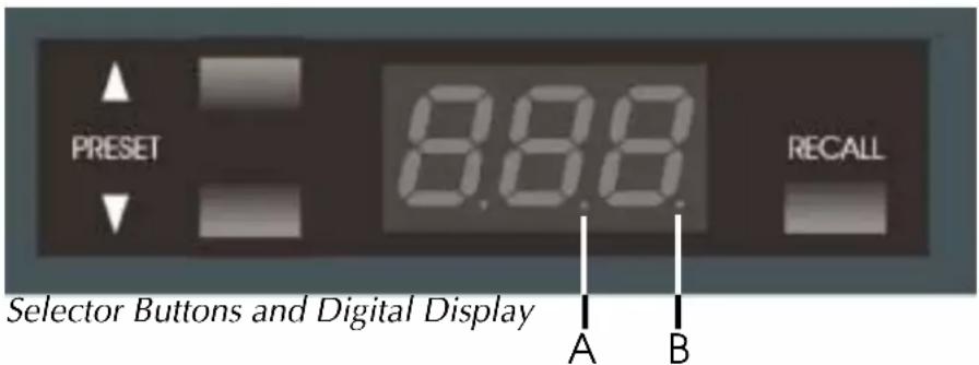
When a parameter is changed, a small indicator (A) momentarily lights to show the parameter has been stored in FLASH memory. Another small indicator (B) is illuminated whenever any parameter is varied from its value within the currently selected Preset.
Front panel control may be 'locked out' via IQ for Windows software. The display reads "Lxx" rather than the usual "Pxx" to indicate the locked status of the controls.
f: Selector Buttons
Two front panel buttons are provided to switch between 'Presets', select 'Scenes', change 'IQ address', and choose RS232 baud rate.
g: RECALL Button
The RECALL button, when pressed and held for longer than 2 seconds, causes the display to cycle through the available choices until it is released; first to 'Scene select' mode, then 'Address select' mode, 'Baud rate select' mode, and finally back to 'Preset select' mode. For more information about these features please refer to the Hardware Installation & Connections section - chapter 9.0.
Once the RECALL button is released, the PRESET UP and DOWN arrow buttons are used to adjust the parameter. On releasing the RECALL button, the user has two seconds to begin using the UP or DOWN arrow buttons before the display changes back to default. When the parameter is adjusted to the desired value, press the RECALL button again to store the setting.
h: IR Sensor
Infra Red (IR) sensor for use with remote control systems such as Philips Pronto. Do not cover! The power indicator will flash when IR commands are received.
i: RS232 connector
Serial port connector for connection to computer using RS232 protocol.
7.0 Rear panel
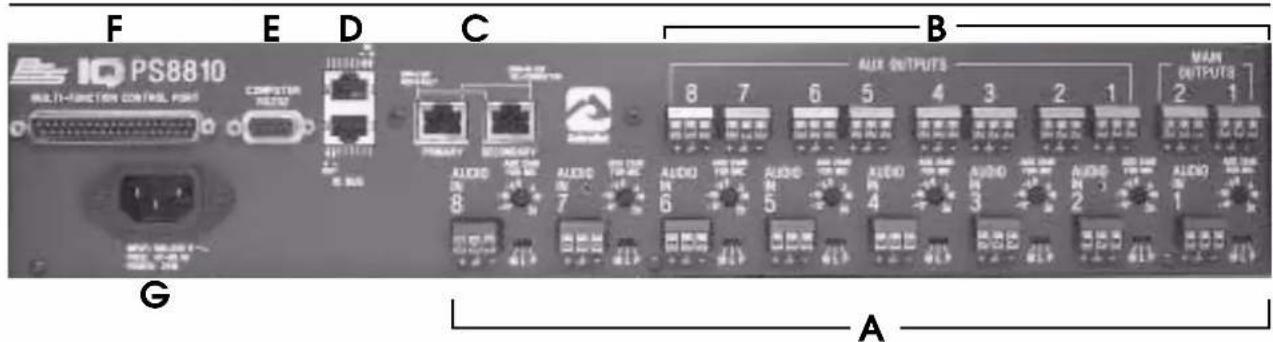
A: Audio Inputs
Three-terminal removable barrier block connectors are provided on the rear panel for balanced analogue audio input.
Input Selector
Each input has a three-position "M L P" selector switch for mic level, line level, or mic level with phantom power.
- Select the M position for microphone signal levels up to +7dBu (0dbu=0.775 volts).
- Select the L position for line level signals up to +32dBu
- Select the P position for mic inputs that require +24VDC 'phantom' power.
Audio Input Gain Control
Each analogue audio input channel has a screwdriver-set, calibrated gain potentiometer for adjusting the input gain to the input signal level. These can be used to compensate for different microphone sensitivities. Control range is from -12dB to +20dB.
B: Audio Outputs
Main and AUX Audio Outputs
A 3-pin removable barrier block plug is provided on the rear panel for each of the 10 analogue audio outputs (Main Outs 1 & 2 and Aux Outs 1-8).
Rear panel
C: CobraNet® Connectors

CobraNet Connections and Indicators
These two RJ-45 connections provide CobraNet access to and from the PS-8810C. This feature is not available on the standard PS-8810 and this area is covered by a blank plate.
The PRIMARY and SECONDARY connectors provide 100Mbit CAT-5 connection to the primary and redundant (secondary) CobraNet networks.
In normal operation, the PRIMARY connection will be active and the left LED will be green to show link connection to the CobraNet network. If network connection is lost, the LED turns red. The right PRIMARY LED will be green when the CobraNet network is connected, and will turn Yellow when the unit is the Conductor.
The SECONDARY connection is similar to the Primary, but is active only in case of a fault in the CobraNet network attached to the PRIMARY. The secondary LEDs work in the same way as the primary ones.
D: IQ Loop Connectors

IQ Loop Input/Output Connector
The upper rear panel RJ-45 connector provides the input from the IQ bus. Dropout relays maintain loop integrity in the event power is removed from the BSS PS-8810.
IQ Loop Output Connector
The lower rear panel RJ-45 connector provides for normal output wiring to the next device on the IQ Loop
E: RS232 Serial Port
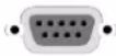
RS232 Serial Port
Female DB9 serial port connectors are provided on both the front and rear panels for direct communication with a PC serial port. Connection to the RS-232 port is available through the front or rear port, but not both simultaneously. Connection to both at the same time will result in errors. The BSS PS-8810 is also capable of serving as the system interface for other IQ components.
Rear panel
F: Control Port

A male DB37 connector is provided on the rear panel for external monitoring and control of objects within the BSS PS-8810. There are eight digital outputs, eight analogue outputs, eight digital inputs and eight analogue inputs available as well as +5V and +10V for powering external circuits.
G: Mains Power Inlet

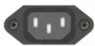
AC Line Connector
A rear panel IEC320 connector is provided for attaching the power cord. The BSS PS-8810 has a universal power supply, and may be operated on AC line voltages from 100VAC to 240VAC at 50Hz or 60Hz.
Using the PS-8810
The following sections describe the BSS PS8810's features and their operation. Where specified, some features are accessed via controls located on the unit itself however, most of the features are configured and controlled using IQ for Windows software.
If you are unfamiliar with IQ for Windows software, please refer to the IQ for Windows Help files, visit the BSS Audio website, www.bss.co.uk or the IQ website, www.iqaudiosystems.com, or contact your BSS representative or BSS Technical Support.
8.0 Quick Install Procedure
This procedure is provided for those who are already familiar with the IQ System and would like to install the BSS PS-8810 in the shortest time possible. Less experienced installers or those wishing a full explanation of the installation procedure are encouraged to refer to the hardware installation section.
Installation:
1 Mount the unit into a standard 19-inch (48.3-cm) equipment rack or cabinet.
Configure the BSS PS-8810:
2 Set input selector switches for Mic, Line, or Phantom, depending upon the type of input signal to be fed to the input.
3 Set audio input gain levels on the back of the unit. See the 'Audio Connections' section for further information regarding suggested settings.
Connections:
4 Turn off all amplifiers or other equipment that will either feed or be connected to the unit.
5 Connect the audio wiring to the BSS PS-8810 inputs and outputs. The wiring should follow the standards as described in the 'Audio Connections' section.
6 Connect directly to the host computer, using either of the RS232 connectors (front or rear), if the unit is to be used as a 'system interface' or as a stand-alone device.
7 Connect the BSS PS-8810 to the IQ System, if available, via the IQ Loop connectors. Connect the IQ Loop wiring to all other IQ components if the unit is to be used as the system interface.
8 If using more than one BSS PS-8810C (or other compatible IQ components) and CobraNet for routing the audio, connect CAT-5 cables from the PS-8810C's PRIMARY
Quick Install Procedure
connector to a 100Mbit dedicated switch. The SECONDARY connector should be wired if a second 'redundant backup system' is to be setup. If using just two units then the primaries and secondaries can be connected directly between the units. To conform to the regulatory agencies, the clamp-on ferrites that are shipped with the unit must be attached to the CAT-5 cables.
9 Connect any circuits to be used with the Control Port connector to the unit.
10 Connect the unit to the AC power supply.
Prepare the BSS PS-8810:
11 Set the IQ address on the BSS PS-8810 to an unused IQ address.
12 If the unit is to be used as a system interface, set the baud rate, and set the unit to act as system interface (green Interface LED on) using IQ for Windows software.
Prepare the audio system:
13 Set all equipment that will be in the signal chain before or after the BSS PS-8810.
14 Set and verify all level and gain settings on all amplifiers or other equipment that will either feed or be connected to the unit.
9.0 Hardware Installation & Connections
An IQ System with a Host Computer and a BSS PS-8810
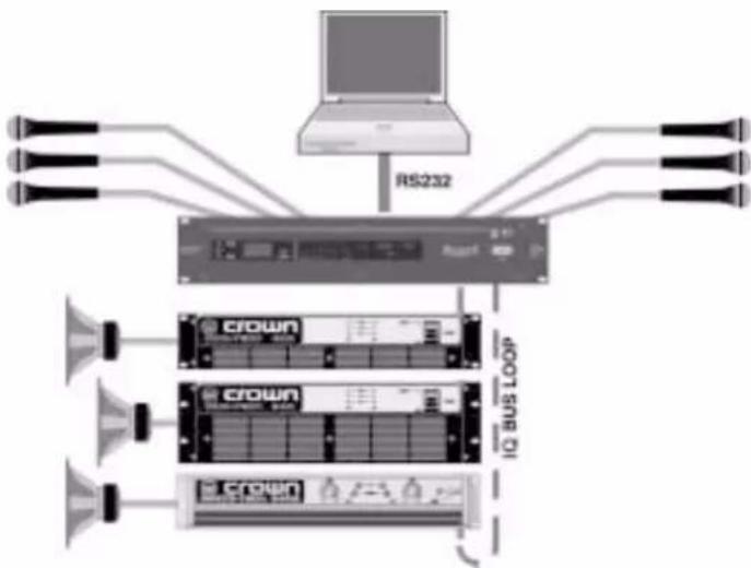
flowchart
graph TD
    A["RS232"] --> B["10x10 bus loop"]
    C["crown"] --> D["10x10 bus loop"]
    E["crown"] --> F["10x10 bus loop"]
    G["crown"] --> H["10x10 bus loop"]
    I["crown"] --> J["10x10 bus loop"]
    K["Link"] --> L["Link to RS232"]
    style RS232 fill:#f9f,stroke:#333
    style 10x10 bus loop fill:#ccf,stroke:#333
    style 10x10 bus loop fill:#cfc,stroke:#333
    style 10x10 bus loop fill:#fcc,stroke:#333
The installation of a BSS PS-8810 consists of installing the hardware and configuring the unit via IQ for Windows (IQ Win) software. An overview of this software starts from section 10.0 of this manual. Refer also to the IQ for Windows on-line Help files for instructions in setting up and operating your IQ software.
The hardware installation can be seen as these steps:
1) Connecting to a host computer
2) Connecting to the IQ Loop
3) Connecting the audio inputs and outputs
4) Connecting to the CobraNet ^® Network (PS-8810C)
5) Connecting auxiliary devices
6) Connecting a modem (if required)
Connections Computer
Connecting to a Host Computer
An IQ host computer is a PC running Microsoft Windows 95, 98, ME, 2000 or NT that is used to configure, control or monitor an IQ System. Depending upon the design of your IQ System, it may or may not require a host computer during normal operation. Third party control systems such as AMX can also be used but, need some fundamental programming before they are able to access the PS-8810's features.
How the BSS PS-8810 will be used will determine whether or not it will need to be connected directly to a host computer. If the unit is to be connected to an 'IQ Loop' it will not necessarily need to be connected directly to a host computer. The following circumstances require connection to a host computer:
- If an IQ Loop is not to be used, the BSS PS-8810 will need to be connected to a host computer so that the unit can be configured. Afterwards, if computer control is not required, the host computer can be disconnected.
- If the BSS PS-8810 is to be configured before it is installed into an IQ System, it must be connected directly to a host computer for configuration. The onboard memory of the unit will maintain its configuration without it being plugged into an AC source.
- If the BSS PS-8810 is to be used as an IQ interface for other IQ System components, it will need to be connected directly to a host computer for configuration of other components during setup, and for IQ control of components during normal operation.
One of the advantages of connecting directly to a host computer is that a separate IQ interface (i.e. Crown IQ_INT-3) is not required. If you plan to configure the unit while it is connected to the IQ Loop, skip ahead to Step 2.
RS232 Computer Connection
RS232 is commonly used with PCs, and is the communication standard supported by the BSS PS-8810 when used as an interface. Because it uses unbalanced signal wiring, it cannot be used for distances over 50 feet (15.2 m).
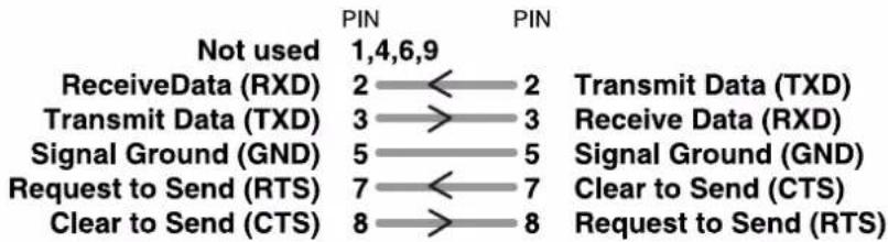
The following illustration shows how to wire the serial cable:
ConnectionsComputer
PC (RS-232) PS-8810 (RS-232)
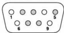
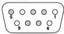
Cable connectors are numbered as they appear from the front.
bar
| Category | PIN | Not used | |---|---|---| | ReceiveData (RXD) | 2 | 1,4,6,9 | | Transmit Data (TXD) | 3 | 2 | | Signal Ground (GND) | 5 | 3 | | Request to Send (RTS) | 7 | 2 | | Clear to Send (CTS) | 8 | 3 | | Transmit Data (TXD) | 2 | 3 | | Receive Data (RXD) | 3 | 5 | | Signal Ground (GND) | 5 | 5 | | Clear to Send (CTS) | 7 | 7 | | Request to Send (RTS) | 8 | 8 |RS232 Cable Wiring
Important: Do not use twisted pair wire for RS232 because it increases crosstalk. Instead, use an untwisted cable or ribbon cable.
Set the Baud Rate
Baud rate for RS232 serial communication is set using the front panel buttons. IQ for Windows software has the capability to adjust automatically to the baud rate of the BSS PS-8810 for maximum performance, so setting the baud rate usually is not necessary; however, the baud rate can be set by using the following procedure:
1 Push and hold the front-panel RECALL button until the display changes from the 'Preset' mode (i.e. "P01") to the 'Scene select' mode (i.e. "S01"), then 'Address select' mode (i.e. "001"), then to 'Baud rate select' mode (i.e. "115").
2 Push the UP or DOWN arrow buttons to select the desired baud rate. The highest baud rate supported by the unit is 115K baud. In most cases, 115K baud is the best setting and is also the default setting. Adjust to a lower baud rate only if you are having difficulty establishing communications with the host computer.
3 When the RECALL button is released, the user has two seconds to begin using the UP or DOWN arrow buttons before the display changes back to the 'Preset' mode.
Connections Computer
4 When the parameter is adjusted to the desired value, press the RECALL button again to store the setting.
The communication parameters of the host computer are set within IQ for Windows software. Please refer to the IQ for Windows Help files for information about setting up communication parameters.
The available baud rates are (in descending bps order):
115200
57600
38400
19200
Comms Problems
Here are some steps to follow if you are having difficulty establishing serial communication:
1 If the host computer fails to communicate with the unit and the communication standard and parameters are set correctly, try reducing the baud rate.
2 Check the serial cable for improper wiring or possible shorted or broken wires.
3 If communication problems persist, check for other programs or hardware in the computer that might interfere.
4 For further assistance contact BSS Technical Support.
Connections IQ Loop
Connecting the IQ Loop
The 'IQ Loop' is a serial communication loop for transmitting IQ commands and data between multiple IQ compatible units. It provides excellent flexibility, allowing a IQ Loop 'loop' to be wired with either fibre optic cabling or with inexpensive twisted-pair wire. A single IQ System can have more than one IQ Loop. To function properly, a IQ Loop must be unbroken.
Set the IQ Address
Every IQ component needs a unique 'address' so that it can then be individually controlled and monitored by the IQWin software and can also coexist on the IQ Loop with other similar units.
An IQ address for the PS-8810 can be any number from 1 to 250. Other IQ components can be set to addresses above 250, but do not do so, because numbers above 250 are reserved for special use. With the BSS PS-8810 address "0" (zero) disconnects external communication.
To set the address:
1 Push and hold the front-panel RECALL button until the display changes to 'Address select' mode, (i.e. "001")
2 Press the UP or DOWN buttons to select the desired address number.
3 Press the RECALL button again to store the address.
The display will automatically return to 'Preset' mode in a few seconds.
No two IQ components of the same type which are connected to the same IQ Loop can have the same address. Suppose, for example, an IQ System has two IQ loops, 1 and 2, and a BSS PS-8810 is to be installed into loop 1 and given an address of 114. No other BSS PS-8810 can be given the same address in loop 1. However, a BSS PS-8810 in loop 2 can have the address of 114, and another type of IQ component can be given an address of 114 in loop 1. For example, both a Crown IQ-PIP-USP2 and a BSS PS-8810 can both use the same address on the same loop.
PS-8810 as a single loop IQ Interface
The BSS PS-8810 can serve as an IQ interface between a host computer and a single IQ Loop for other IQ components. This can eliminate the need for an external IQ Interface (i.e. IQ INTII) in a small system. The BSS PS-8810 connects directly to the host computer via the DB9 RS232 serial connector.
Connections IQ Loop
One of the units must be set as the 'Master' for the IQ Loop, this is done by setting its 'IQ interface' LED to light using the IQWin software.
In order to use more than one PC with the IQ loop the IQNET server software must be used, please refer to the IQNET Server help for more information.
PS-8810 in an IQ Loop system
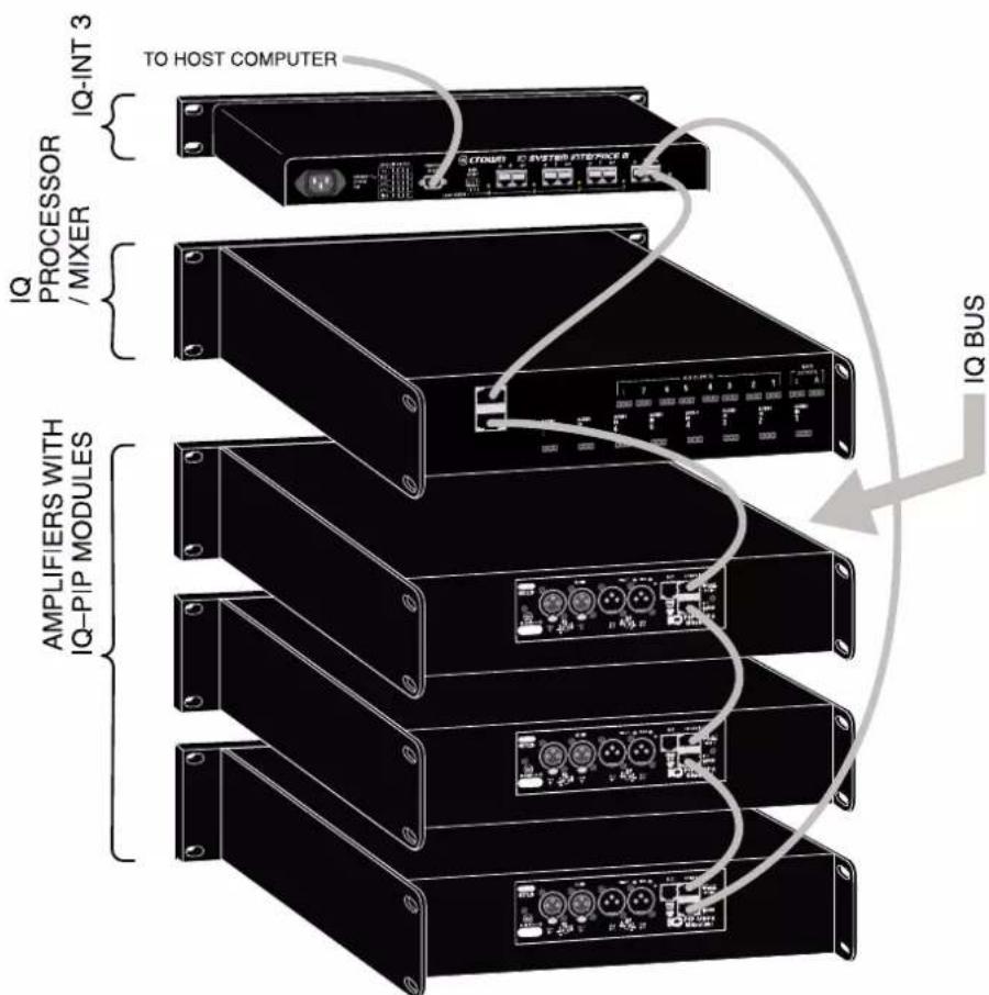
The IQ components in a IQ Loop are wired sequentially. The loop begins and ends with the IQ interface. The output of one IQ component 'loops' to the input of the next and so on as shown below.
IQ Loop wiring 'Loop' from Output to Input of each IQ component
Connections IQ Loop
IQ Component Connections
Three different types of connectors are used for IQ Loop wiring on IQ components. These include DIN connectors, RJ-45 connectors, and removable barrier strip plugs. Connection details for these differing types of connectors are found in the following pages.
The BSS PS-8810 uses RJ-45 connectors that accept plugs like the one shown below.
RJ-45 Plug
When wiring RJ-45 connectors, it is good practice to follow the EIA/TIA 568B protocol for RJ-45 connector cable. This protocol assigns wire colours as follows:
1 white-orange 5 white-blue
2 orange 6 green
3 white-green 7 white-brown
4 blue 8 brown
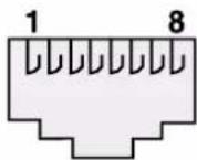
RJ-45 Pin Numbers
When attaching RJ-45 connectors to cable, be sure to use the appropriate crimping tool and verify that the connector is properly seated into the tool or damage will result.
The following examples show how to connect the BSS PS-8810 to other IQ components on the IQ Loop:
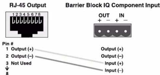
RJ-45 Output to Barrier Block Input
Connections IQ Loop
RJ-45 Output
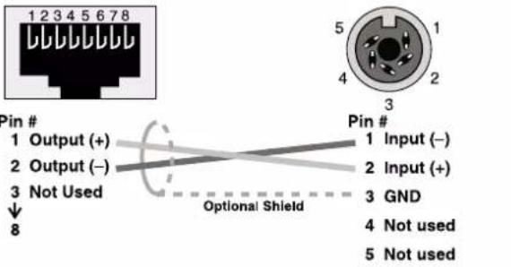
RJ-45 Output to Din Input
Barrier Block IQ Component Output
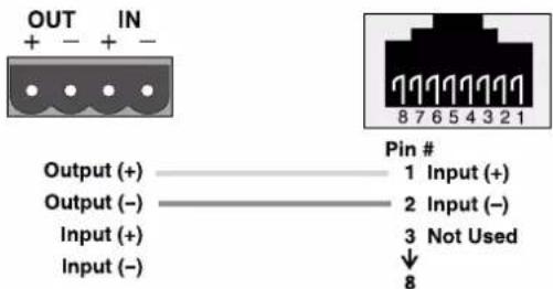
Barrier Block Output to RJ-45 Input
Din IQ Component Output
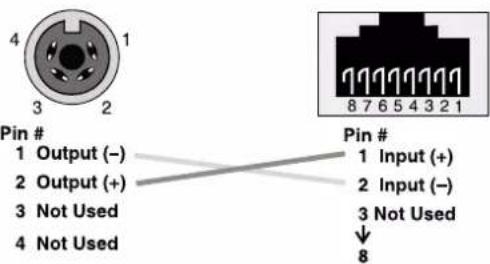
Din Output to RJ-45 Input
RJ-45 IQ Component Output
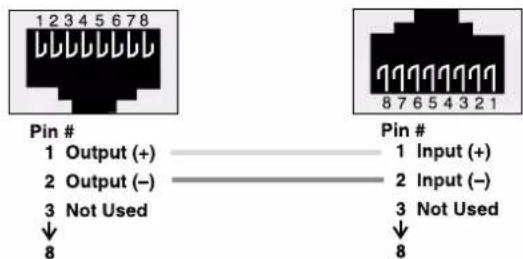
RJ-45 Output to RJ-45 Input
Connections IQ Loop
IQ Loop Wiring
As implemented in the BSS PS-8810 the IQ Loop is a 20-mA current loop operating at a baud rate of 38.4kbps. The IQ Loop must be unbroken.
The IQ Loop connection can use inexpensive twisted-pair wiring (shielded or unshielded). Here are some guidelines for twisted-pair wiring:
- When interference is a problem, use shielded twisted-pair wire at least 26 AWG in size. The wire should be of good quality and should have low capacitance (30 pF/foot or less is suitable).
The shield serves two purposes:
1 It helps prevent the IQ data signal from transmitting to nearby audio wiring.
2 It helps prevent outside RF from interfering with the data signal. However, in most cases interference is not a problem and, since unshielded wire has lower capacitance, it is a better choice for typical applications.
- Minimize the total capacitance of an IQ Loop. The total combined capacitance for a IQ Loop should be less than 30 nF. To calculate this, allow approximately 60 pF for each IQ component in a loop. This accounts for a slight signal degradation which occurs as data signals pass through a component.
- Add an IQ Repeater for very long loops—greater than 1,000 feet (305 m)—or when required by high-capacitance wire.
Although BSS recommends adding a repeater for loops longer than 1,000 feet, it is sometimes possible to go 2,000 feet (610 m) or more before a repeater is required. The most significant factor in determining maximum loop length is wire capacitance. Lower capacitance will allow longer loops (unshielded wire usually has lower capacitance).
Outside RF interference is seldom a problem for an IQ Loop especially if shielded twisted-pair wire is used. However, there are extreme situations when fibre optic wiring is recommended. For example, locating a IQ Loop next to an AM radio transmission line may require fibre optic cabling. An extremely long IQ Loop distance may also require fibre optic cabling. Contact BSS If fibre optic cabling is required.
Connections Audio
Audio Wiring
The BSS PS-8810 has eight mic/line inputs, two main outputs and eight AUX outputs Three-terminal removable barrier block connectors are provided for the mic/line inputs and main and AUX outputs.
About the Audio Inputs
Three-terminal removable barrier block connectors are provided for the audio inputs.
Each input has an input selector switch.
- Slide it to the left (M) for microphone signal levels up to 5dBu (0dBu = 0.775 volts).
- Select the center position (L) for line level signals up to +20 dBu.
- Slide it to the right (P) to provide 24VDC to mics requiring phantom power.
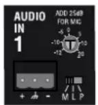
An Audio Input Section
Each input has a screwdriver-set, calibrated gain control to compensate for different input source levels. The slot on the control shaft points to the gain setting. The settings are labelled for line level input. Add 25 dB to the scale if the inputs are switched for microphone level signals.
Use a screwdriver to adjust the gain pot so that the input signal level plus gain equals roughly 0dBu. You will need to know, or estimate, the level of the input source. Setting the source signal level to approximately 0dBu will provide 20dBu of headroom in the input preamp. Some recommended settings are given in the following table.
Connections Audio
Suggested Audio Input Gain Control Settings
| Pro Audio equipment | Semi-Pro or consumer equipment | Dynamic mic, speech | Condenser mic, speech | Hot condenser mic, speech | Dynamic mic, music | Hot condenser mic, music | Close-miked dynamic mic, bass/drums | Close-miked dynamic mic, kick drum, guitar amp | |
| dBm/dBV (nominal) | +4 dBm | -10 dBV | -75 dBV | -65 dBV | -45 dBV | -55 dBV | -25 dBV | -15 dBV | -5 dBV |
| dBu (nominal) | +4 dBu | -8 dBu | -73 dBu | -63 dBu | -43 dBu | -53 dBu | -23 dBu | -13 dBu | -3 dBu |
| Suggested Setting | -4 (L) | +8 (L) | +20 (M) | +18 (P) | +11 (P) | +20 (M) | -2 (P) | -12 (M) | -12 (M) or +3 (L) |
0 dBm = 0.775 VRMS with a 600-ohm load, 0 dBV = 1 VRMS, 0 dBu = 0.775 VRMS
Balanced Input Wiring
Balanced sources should be wired as shown below. Notice that the shield is not connected to the chassis ground of the source if the source is also connected to the AC ground (that is, it has a grounded AC plug). This prevents unwanted ground loops.
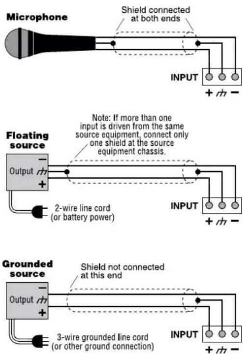
Balanced Audio Input Wiring
Connections Audio
Unbalanced Input Wiring
Unbalanced sources should be wired as shown below. The examples are grouped according to whether twin lead shielded wire or single conductor coax (or twisted pair) wire is used.
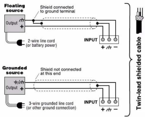
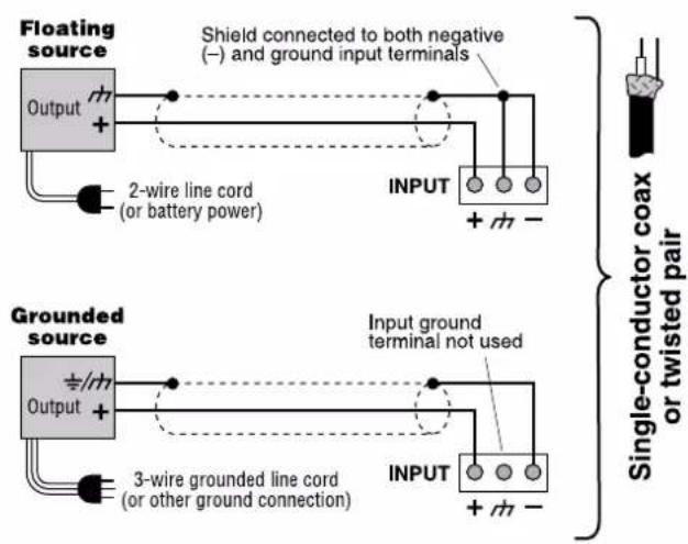
Unbalanced Audio Input Wiring
Connections Audio
About the Audio Outputs
Three-terminal removable barrier block connectors are provided for audio output (Figure 6.5). Both main and AUX Audio Outputs are balanced and can drive 1200 ohms or more to +20 dBu.
The two Main outputs and the eight AUX outputs allow the BSS PS-8810 to act as a 24x10 matrix mixer. The sixteen Input Processing Sections along with the eight CobraNet Inputs (PS-8810C only) allow full mixing of any of the inputs to any of the 10 outputs.
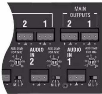
Back Panel Output Connectors
Balanced Output Wiring
Balanced output wiring is shown below. Notice that if the load is connected to AC ground, the shield should not be connected to the output ground terminal. This will prevent unwanted ground loops.
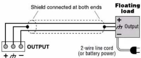
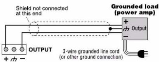
Balanced Audio Output Connections
Connections Audio
Unbalanced
Output Wiring
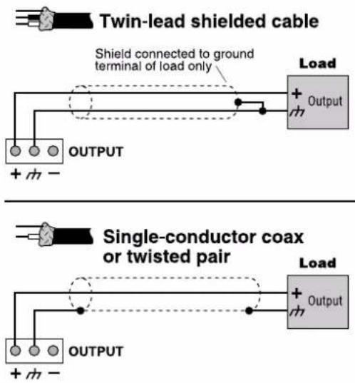
Unbalanced Audio Output Connections
CobraNet® Connections
The CobraNet network carries 8 channels of audio bidirectionally via a single cable. Connect the PS-8810C to the CobraNet network using RJ45 terminated standard CAT-5 cable from the PRIMARY connector on the rear of the unit.
The PRIMARY connection can either be connected to another PS-8810 unit or other CobraNet compatible component's PRIMARY port. A further option is to connect to a port on a 100Mbit Ethernet switch or hub in order to distribute the network audio to other devices. Devices that are to communicate with the PS-8810 will all need unique ethernet IP addresses assigned - see the CobraNet section for more details.
The SECONDARY connector is for creating a redundant network for backup purposes. This port should be tied to the backup Ethernet network. In the event of a failure in the cabling or hardware connected to the PRIMARY system the PS-8810 will switch to the SECONDARY network in a matter of seconds.
There are two LEDs built in to the RJ45 sockets on the back of the unit, these indicators represent the network status.
The left hand LED should light green when a cable that is connected to an active CobraNet network is plugged in. This LED will flash to show the presence of network traffic but will light red if there is a fault. Possible faults could include cabling or hardware problems and network collisions (often when installed into an ethernet switch running a lot of network information).
The right hand LED is green even when no cables are wired to the port as it represents the active status of the CobraNet hardware. The LED will change colour to yellow when the unit has become the 'conductor', i.e. is the network master. See the CobraNet section for more details.
Connections CobraNet
®
In order for the system to conform to the stated regulatory requirements, clamp-on ferrites that are shipped with the unit must be attached to the PRIMARY and SECONDARY CobraNet cables. Be sure to double loop the cable in the ferrite.
Connections Control Port
Control Port Connections
Connect any external circuits you plan to use to control and/or monitor the BSS PS-8810 via the Control Port. The diagram below shows pin assignments for the Control Port. See the Control Port (Section 16.0) for information on the operation of the Control Port, and for examples of wiring circuits to the Control Port connector.
PS-8810 Control Port (DB37)

PIN PIN PIN PIN
1 D OUT 1 10 GND 19 D IN 8 28 GND
2 D OUT 2 11 GND 20 A OUT 9 29 +10V
3 D OUT 3 12 D IN 1 21 A OUT 10 30 A IN 1
4 D OUT 4 13 D IN 2 22 A OUT 11 31 A IN 2
5 D OUT 5 14 D IN 3 23 A OUT 12 32 A IN 3
6 D OUT 6 15 D IN 4 24 A OUT 13 33 A IN 4
7 D OUT 7 16 D IN 5 25 A OUT 14 34 A IN 5
8 D OUT 8 17 D IN 6 26 A OUT 15 35 A IN 6
9 +5V 18 D IN 7 27 A OUT 16 36 A IN 7
37 A IN 8
Control Port Pin Assignment
Pins 1 through 8 are assignable to manually select a binary (on/off) value, chosen Preset status, or status of any logical binary control or sensor (most likely gate and Preset).
Pins 20 through 27 provide an analogue output from 0 to +10VDC that is assignable or can reflect an object (including faders) of the unit.
A total of 1 amp of current is available from all outputs.
Pins 12 through 19 are assignable to logic Preset recall and general control for logical type objects within the unit, and are assignable to any combination of mute controls. Pins 30 through 37 function as analogue inputs and are assignable to any combination of fader controls.
Connections Modem Connection
Modem Connection
The BSS PS-8810 is also modem compatible. The BSS PS-8810 periodically sends out an "AT" command string {ATS0=1} that automatically initializes a connected Hayes compatible modem to its max baud rate and auto-answer mode. The link is non handshaking.
A standard null modem cable should be used between the interface and modem with the exception of pin 4. Pin 4 of the 9-pin RS232 connector on the back of the interface should NOT be connected. This configuration is not compatible with some 232/null modem applications.
When using a modem it may be necessary to set the front panel baud rate at a level lower than the modem data speed, e.g. 192 (19200bps) for a 56kbps modem (true upload speed is only 33600bps). This is to ensure clean data transfer between the PS-8810 and remote computer however, feel free to experiment with the higher speeds if a reliable rate can be found.
Refer to the diagram below for modem wiring detail.
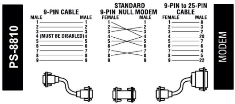
Modem Hook-up

This section describes how to set up the PS-8810 from within IQ Win software and includes an overview of the various processing functions and associated windows.
10.0 IQ Win Overview
The PS-8810 is configured using IQ Win software. This application enables the setup of all the parameters available to the DSP of the ProSys unit.
PC Requirements
To run IQ Win successfully a 200Mhz Pentium II (preferably 400Mhz or better) machine with an absolute minimum of 32MB RAM (64MB or more is better) is recommended. IQ Win will run under Windows 95/98/ME/NT or 2000 (2000 Pro recommended)
System Overview
The PS-8810 is a 'fixed path' processing unit, this means that the audio signal travels along a set course of DSP objects, these objects can be switched in or out of the path and in some instances matrix routed into other paths. The 'Signal Path' tab in the PS-8810 setup window in IQ Win displays an overview of the main DSP, input / output routing and the various processing objects in them. This is where most of the PS-8810's DSP configuration is accessed. More information about this 'map' is available in chapter 11.0 Processing Functions.
All 8 analogue inputs are divided into two separate paths (A&B - denoted by the colours green for A and blue for B) that can be processed independently allowing a sub or monitor mix to be set up easily, i.e. there are 16 input processing sections available. With the addition of CobraNet a further 8 channels can be routed through the unit.
Presets and Scenes
The basic premise in setting up the PS-8810 is that the unit should be configured for a particular use and this setup then stored as a Preset in the unit (shown as "P" and a 2 digit number between 00 and 32 on the ProSys LED display). There are also Scene memories (denoted by an "S" on the front panel display), that store just the settings of up to 50 of the DSP objects but, not the configuration of objects.
Presets or Scenes can be primed to change at set times or dates using the 'Unit Event' scheduler giving a reasonable degree of flexibility not unlike other show controllers. A Preset segue function enables Presets to be crossfaded in level for smooth transitions between setups.
IQ Win itself can also switch between different setups including combinations of units wired via the IQ interface. The Dataframe contains all the information for all the devices on the IQ network and is saved as a .WIQ file on the PC's hard drive. Different
versions of these files that pertain to the same hardware setups can then be scheduled to change using the Schedule function in the File menu and this can even be linked to MIDI Time Code using the MTC Scheduler in the Setup menu.
A further level of control is also available using IQ Win Scenes, these are not the same as the Unit Scenes that can be set up for the PS-8810 alone. These can be scheduled using the Scene Sequencer found in the Dataframe menu and are again saved on the PC hard drive (as .SIQ files). IQ Win Scenes can be organised without any units connected to the PC, unlike PS-8810 Presets that can only be stored in the unit while the program is on-line to the device.
IQ Win Notes
If you use the Cut command from the Edit menu on a PS-8810 icon in the Workplace this will not delete the unit but, instead removes all the settings back to their defaults. Equally, Copy will put the settings on the clipboard for Pasting back into another unit (if you have two or more on an IQ loop for example).
All of the settings in the unit can be printed in list format using the File menu Print command. This is useful to assess the configuration of the device on paper although, note that for a standard PS-8810 the printout will run to over 20 pages! Use the 'Select' button to choose for which unit(s) you wish to print the settings.
The Upload and Engage options in the Dataframe menu enable a manual connection to be made either from the unit in the former case or back to the unit in the latter. All the current settings will be either received or sent to the PS-8810. These functions can be used to re-establish communication with the unit should the link go down, i.e. the RS232 cable is accidentally unplugged.
The Edit Control Pages option allows the construction of 'custom' control panels to give selective access to particular controls and to represent them in a user's chosen layout with added text and images.
IQ Win also includes some comprehensive error reporting facilities that can be linked to a printer or sent out externally via a connected modem to either a fax or pager. A .wav audio file alert can even be played through the system! Note that at present the error reporting doesn't include information relating to CobraNet
IQ Win Overview
installations. Error reporting can be suppressed if necessary - this is useful in larger systems where there may be too much generation of data.
A security system is implemented using a set of passwords to protect almost any aspect of the software's functionality from unauthorised access or alteration. Passwords can be set to secure:
- Running the IQ Win program
- Creation of new Dataframes/Scenes
- Access to the current Dataframe
• Operation/editing of component controls - Setup of Scene sequences
The Administrator mode gives access to all passwords with one single password.
Some passwords are program based, e.g. run program, create new Dataframe/Scene and Administrator. The current Dataframe, Component controls and Scene sequence passwords are saved with the Dataframe in the .WIQ file itself.
The following section describes how to get up and running with a PS-8810 and IQ Win and then gives an overview of the various processing function windows found in the PS-8810 configuration section of IQ Win.
Quick Set Up
IQ Win software is used to configure the PS-8810. This is a free download from the IQ Audio Systems web site at www.iqaudiosystems.com. At the time of writing this software is at version 5 and some elements of the interface and functionality may change if a newer version is released. The following Quick Set Up guide assumes that you have installed a copy of the IQ Win software on the PC that you wish to use to configure the PS-8810.
1 Connect the PC to the PS-8810 via the RS232 connector and make sure that the unit is plugged in and powered up. See the Connections section for more information on cabling if required.
2. Launch the IQ Win program. The 'Component Discovery' window should appear and the PS-8810 should be auto detected. This is called the 'discovery process', where IQ Win performs a 'roll call' to find connected units by scanning all the PC's com ports. The correct com port setting is stored in the IQ Win .ini file for quicker detection on the next application launch. The baud rate should also be automatically set. Once the process is finished and if a unit is detected IQ Win will then upload its settings.
If it isn't, or the PS-8810 isn't powered up yet, then press the 'Abort' button and you will be taken into the IQ Win Workplace area. In this case the unit can be manually added by going to the 'Dataframe' menu and selecting 'New Components'. Choose either PS-8810 or the PS-8810C if you have CobraNet capability. Enter a number, i.e. "1" in the Address box and press 'OK'.
-
A representation of the PS-8810 should appear in the Workplace area. Double click this image to edit the PS-8810's parameters.
-
A window with input / output level meters on its left and a graphic of the front panel should be displayed under the 'General' tab. See chapter 11.0 Processing Functions for more information about the various windows associated with these tabs.
You are now ready to start configuring the PS-8810.
11.0 Processing Functions Metering & Status
Metering
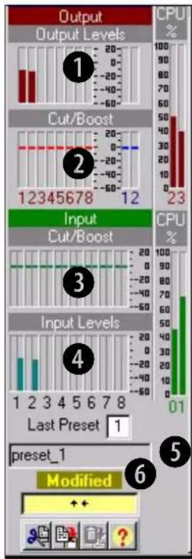
7
IQ Win Input Path Control Window
① Output Level Meters
Audio level meters are provided for each output. The meters sense the audio signal immediately after the audio output processing block.
Meter range is from -60 to +20dBu with 0.5dB resolution.
② Output Dynamic Cut/Boost Meters
Meters are provided for each output to indicate the overall cut or boost being applied from all output signal processing features that affect output gain, including Ambient-Leveler and Output Limiter.
Meter range is from -60 to +20dBu with 0.5dB resolution.
③ Input Level Meters
Audio level peak program meters are provided for each of the sixteen Input Processing Sections. The meters sense the digital audio signal, and respond with 1.7 millisecond attack and 350 millisecond release. Calibration is in dBu when the input is in 'line' mode and set at 0dB.
Meter range is from -60 to +20dBu with 0.5dB resolution.
Processing Functions Metering & Status
④ Input Dynamic Cut/Boost Meters
Meters are provided for each Input Processing Section to indicate the overall cut or boost being applied from all signal processing features that affect input gain, including Auto-leveler, Input Compressor, and Automixing.
Meter range is from -60 to +20dBu with 0.5dB resolution.
⑤ Preset Information
These windows indicate the Preset that is currently displayed and also shows the label associated with that Preset. The Preset can be changed by IQ Win, the front panel of the unit, by the event scheduler, or by a programmed control port input.
⑥ Status Window
This window shows the current status of the unit and has three modes:
- "Active" (green): Indicates that the settings of the unit agree with the displayed Preset.
- "Modified" (yellow): Indicates that the settings of the unit are different from the displayed Preset.
- "Offline" (red): Indicates that IQ Win is not currently in communication with the unit.
⑦ CPU Utilisation
The PS-8810 has a substantial amount of DSP processing capability, but each function requires a certain amount of processing time. These four CPU meters indicate the amount of processing capability that remains. On start-up these meters will probably indicate some percentage of usage even if none of the processing sections have been enabled, this is due to the 24x10 matrix router and is quite normal.
Processing Functions DSP
DSP The DSP processing is divided between four individual DSP's; two for the input processing and two for the mixing and output processing.
- DSP 0 does the processing for input channels 1 through 4
- DSP 1 takes care of 5 through 8.
- DSP 2 is responsible for output processing of Main 1 and AUX 1 through 4
- DSP3 has Main 2 and AUX 5 through 8.
Each processing requirement is monitored by the CPU utilisation meters and additional processing is not allowed after the DSP is 95% utilized.
To conserve CPU usage, turn off any processing on unused input and output processing sections. Also, each output's matrix mixing requires about 6% processing, so solo unused outputs to one input rather than a full mix.
Processing Functions General
General
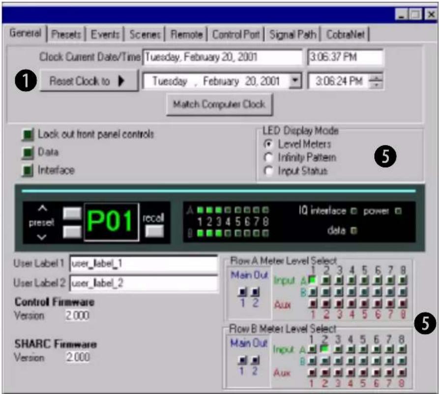
① Real Time Clock
The onboard Real Time Clock tracks day, date, hour, minute and second, and may be set to any date and time desired, or to match that of the computer running IQ for Windows software. The clock is used as a time reference for the Events Scheduling feature. Internal capacitor storage allows the clock to run for up to 45 days without power being applied to the BSS PS-8810.
② Front Panel Control Lock Out
Activation of this control prevents access to the front panel controls. When active, the front panel display will indicate "Lxx" to show that the front panel is not accessible. If a front panel control is pressed, the display will show "Loc", reminding the user that the front panel is locked.
③ Data
This control allows the user to light the front panel "DATA" LED continuously. This is handy as a diagnostic tool to show IQ communications to a particular unit.
Processing Functions General
④ Interface
When activated the PS-8810 acts as the IQ interface 'master', allowing itself and other components on the unit's IQ loop to communicate to a host computer connected via its RS232 port.
Note that only one PS-8810 can be the interface on a loop and that each type of IQ component must have a unique IQ address.
⑤ LED Display Mode
The sixteen front panel 'STATUS' LED's can be used to display a variety of information. They can be used to horizontally provide meter status information for two selected input or output audio channels. In addition, the LED's can indicate the input gate status of the sixteen Input Processing Sections, lighting when the gate is open. The meters can also provide an 'infinity pattern' that can be used to provide diagnostic information, not all that useful, but it does look cool!
⑥ Front Panel Access
The mock front panel allows monitor and control of the unit just as if you are pushing the front panel controls. Preset switching, access, and status monitoring are available through this control.
⑦ User Labels
The user labels can be used to convey useful information about the unit. User label 1 is also displayed in the title bar.
⑧ Firmware Information
The version of the Control firmware and SHARC (DSP) firmware is displayed. This is useful to ensure that the current firmware is installed.
Processing Functions Signal Path
Signal Path
flowchart
graph TD
    subgraph Inputs
        A1["1"] --> A2["1A"]
        A2 --> A3["1B"]
        A3 --> A4["2A"]
        A4 --> A5["2B"]
        A5 --> A6["3A"]
        A6 --> A7["3B"]
        A7 --> A8["4A"]
        A8 --> A9["4B"]
        A9 --> A10["5A"]
        A10 --> A11["5B"]
        A11 --> A12["6A"]
        A12 --> A13["7A"]
        A13 --> A14["Aux"]
        A14 --> A15["1"]
        A15 --> A16["2"]
        A16 --> A17["3"]
        A17 --> A18["4"]
        A18 --> A19["5"]
        A19 --> A20["6"]
        A20 --> A21["7"]
        A21 --> A22["8"]
    end

    subgraph Auto-mix
        B1[" "] --> B2[" "]
        B2 --> B3[" "]
        B3 --> B4[" "]
        B4 --> B5[" "]
        B5 --> B6[" "]
        B6 --> B7[" "]
        B7 --> B8[" "]
    end

    subgraph Matrix
        C1[" "] --> C2[" "]
        C2 --> C3[" "]
        C3 --> C4[" "]
        C4 --> C5[" "]
        C5 --> C6[" "]
        C6 --> C7[" "]
        C7 --> C8[" "]
    end

    subgraph Groups
        D1[" "] --> D2[" "]
        D2 --> D3[" "]
        D3 --> D4[" "]
        D4 --> D5[" "]
        D5 --> D6[" "]
        D6 --> D7[" "]
        D7 --> D8[" "]
    end

    subgraph Solo/Mute
        E1["6A"] --> E2["1"]
        E2 --> E3["2"]
        E3 --> E4["Aux"]
        E4 --> E5["3"]
        E5 --> E6["4"]
        E6 --> E7["5"]
        E7 --> E8["6"]
        E8 --> E9["7"]
        E9 --> E10["8"]

    end

    subgraph Outputs
        F1["1"] --> F2["Main"]
        F2 --> F3["Aux"]
        F3 --> F4["Main"]
        F4 --> F5["Main"]
        F5 --> F6["Aux"]
    end

    style Inputs fill:#f9f,stroke:#333
    style Auto-mix fill:#ccf,stroke:#333
    style Matrix fill:#cfc,stroke:#333
    style Groups fill:#fcc,stroke:#333
    style Solo/Mute fill:#cff,stroke:#333
    style Outputs fill:#ffc,stroke:#333
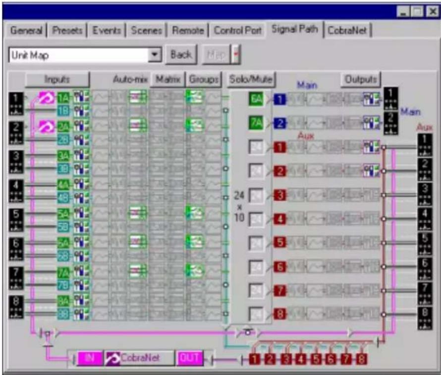
The PS-8810 is an 8 analogue input/10 analogue output digital signal processor and matrix mixer that also has the capability of routing 8 digital inputs and 8 digital outputs from a CobraNet network when the PS8810C or CobraNet card is used.
The 8 rear panel analogue inputs and the 8 CobraNet inputs are available to each of the 16 Input Processing Sections through a switch. The sixteen Input Processing Sections are divided into eight pairs (A & B) that share a common rear panel analogue input or CobraNet input. For example, Input Processing Sections 1A and 1B can have either Analogue Input 1 or CobraNet Input 1 as their input. All sixteen Input Processing Sections are identical. The outputs of the Input Processing Sections are fed to the 24 x 10 Matrix Mixer.
In addition, the output of the 'B' Input Processing Sections are available to the eight CobraNet outputs. These CobraNet output routing switches allow either the output of the 'B' Input Processing Sections or the output of the AUX Output Processing Sections to be sent to the eight CobraNet outputs.
Processing Functions Input Path
Input Path
1
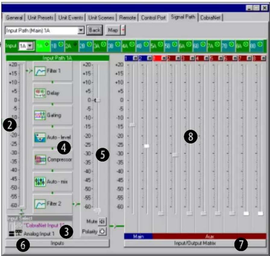
This panel is accessed by clicking on either the input select buttons or the first object (Input Level/Polarity/Mute) in the Signal Path for the required channel.

Input Selector
Choose which input channel to view by either pressing the blue or green input channel required or, pick an input from the drop down box.

Input Meter
The switched input signal is sampled and displayed.

Input Select Switch
The signal that is input to each of the Input Processing Sections can be either the associated analogue audio signal from the rear panel or the associated CobraNet input.

Input Processing Selection
Displays the DSP processes available to the selected input path, if the icons are coloured the processes are enabled. Click on the
Processing Functions Input Path
process box in order to edit its parameters.
⑤ Input Signal Fader, Muter, and Inverter
The output of each of the Input Processing Sections has a fader associated with it prior to the Matrix Mixer. In addition, the Input Processing Section has a muter and inverter.
6 Output Overview
This area enables routing of the selected input to the 10 analogue output channels. A fader and meter is provided for each routing.
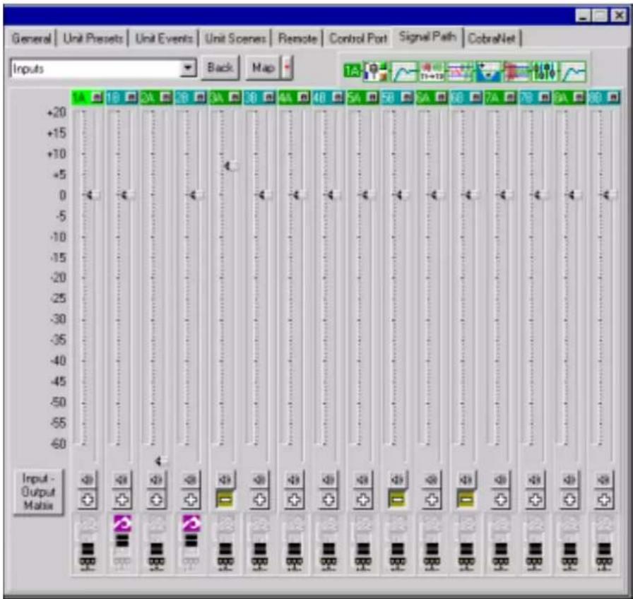
⑦ Inputs Window Link
This button opens a further window that displays all the input gain faders with level meters, mute, polarity and input select switches. It all provides an overview of the Input Processing Section DSP processes that are enabled/disabled for the selected input channel.
⑧ Input/Output Matrix Link
This button opens the Input/Output Matrix window, as described next.
Processing Functions Input Filters
Input Filters
line
| Time | Gain in dB | |------|------------| | 50 | 0.0 | | 10k | 18.0 |Type
The Input Filters provide an array of filter types for any processing need:
Low-pass
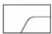
High-pass
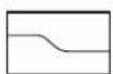
Low-pass Shelf
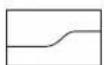
High-pass Shelf
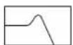
Low-pass EQ
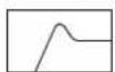
High-pass EQ
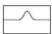
Parametric EQ
Frequency
All filters are frequency adjustable from 20-20KHz
Gain
Gain is adjustable from +24dB to -24dB.
Processing Functions Input Filters

Each DSP is capable of 64 filters that must be shared between Input Processing Sections. In addition to preprocessing filtering, there is post-processing filtering and side-chain filtering associated with each gate. Each individual filter can be switched off or the entire processing filter section can be turned on or bypassed.
Band EQ
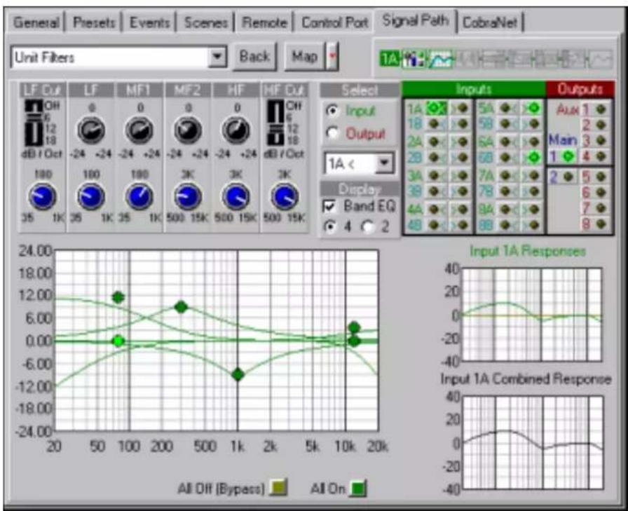
For those who wish to use a more standard Band EQ filter, the Display function allows a 2 band or 4 band EQ with knobs on.
Shape
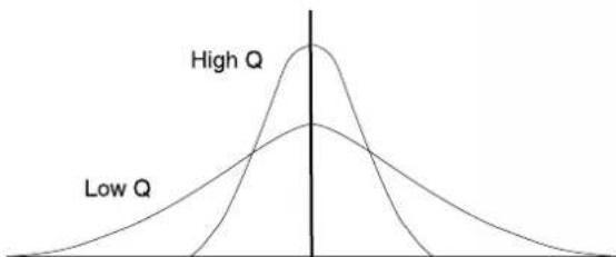
Low-pass and High-pass shapes can be selected from Butterworth 1-4, Bessel 2-4, or Linkwitz-Riley 4. Shelving filters allow low-pass or high-pass filtering with adjustable shelf gain. Equalization filters (Low-pass, High-pass, and Parametric) allow adjustable gain of the peak and control over the Q of the filter.
line
| Category | Peak Value | | -------- | ---------- | | High Q | High Q | | Low Q | Low Q |Care should be taken when using EQ filters to limit the overall gain.
Processing Functions Input Filters

High Q filters with gain greater than unity can cause unwanted ringing. This is true for both digital and analogue filters and should be used with great care.
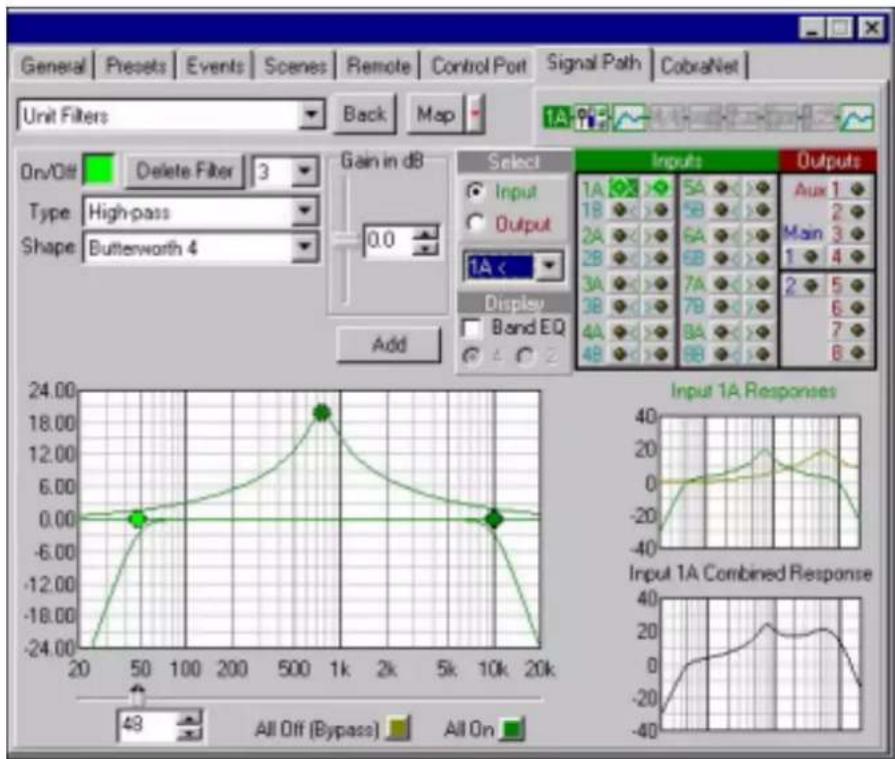
Each filter is shown graphically in the larger window and can be controlled by clicking on the filter 'nodes' and moving them.
The responses of the preprocessing filters and post-processing filters are displayed in the smaller Input Response graph to the right of the main curve display.
The Input Combined Response graph shows the summed total of the two filter sections; an actual frequency composite of the filter networks for that input.
Post-Processing Filters
Additional filtering is available after all of the input signal processing and is identical in operation to the Input Filters.
Processing Functions Input Delay
Input Delay
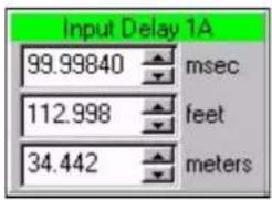
A delay can be added to any of the Input Processing Sections in order to time-equalize the various input signals. Delay is displayed in IQ for Windows software in time, feet, and meters. Control range is from 0 to 100 milliseconds in 20 microsecond steps. Delay time can be adjusted up to a maximum of 2 seconds for each channel.
Hardware Delays
The delays in the PS-8810 are fixed and allow very precise alignment of audio signals. Delay elements are available in each Input Processing Section to ensure that audio alignment is attained. The processing time delays of each of the various components in the PS-8810 and CobraNet network need to be taken into account in this alignment process. These are fixed latencies in order to keep filter alignment together.
The various delays in the PS-8810 and PS-8810C are:
- Input A/D Converter: 667us
• DAC Converter: 520us - Input Processing: 1.665ms
• Output Processing: 1.665ms - CobraNet: 5.333ms
Processing Functions Input Gate

Input Gate
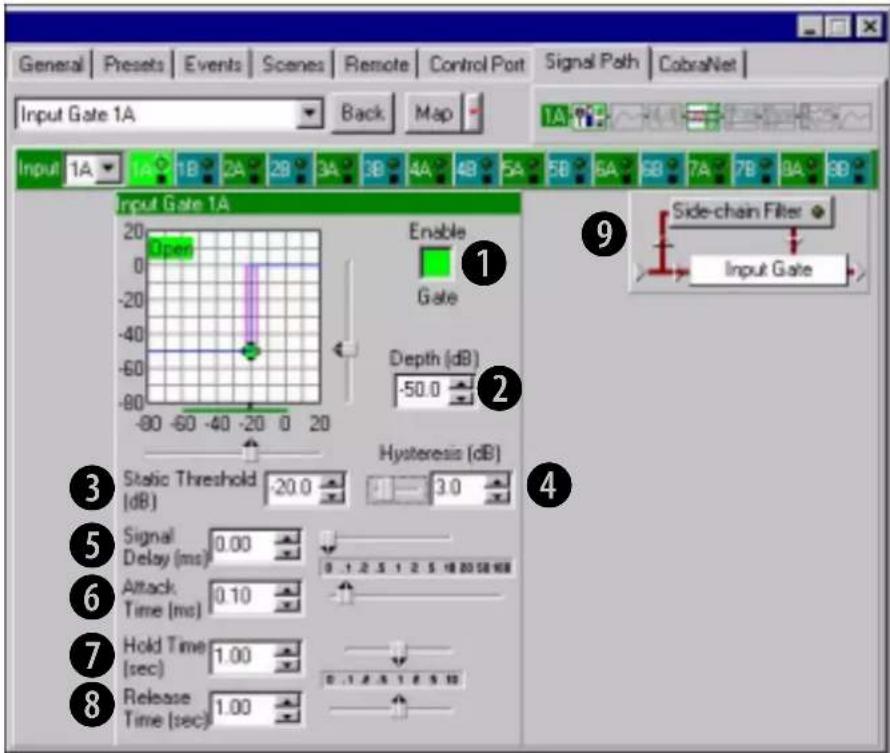
The Input Gate feature allows signals above a certain level to pass and attenuates lower level signals. When 'open', the Input Gate passes the input signal un-attenuated. When 'closed', it attenuates the input signal by an amount specified with the Depth control.
There are eight parameters which control this feature:
① Enable Gate
Switches the gate on or off.
② Depth
Sets the 'closed' gain of the Gate.
Control range is from -100dB to 0dB in 0.5dB steps
③ Static Threshold
Specifies the peak signal level (after side-chain processing) above which the gate will open.
Control range is from -80 to +20dB in 0.5dB steps
④ Hysteresis
Sets a range in dB above and below the Threshold which separates the levels at which the Input Gate opens and closes. The input signal must reach a level above the Threshold plus Hysteresis to
Processing Functions Input Gate
open. Once opened the input must reach a level below the Threshold minus Hysteresis to close.
Control range is from 0dB to 12dB in 0.5dB steps
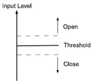
⑤ Signal Delay
Additional delay applied to the input signal, but not to the control key signal. Provided to allow the Input Gate to 'look ahead' in time.
Control range is from 0 milliseconds to 10 milliseconds
⑥ Attack Time
Sets the time required for the Input Gate to increase its gain by 20dB.
Control range is from 0.2 milliseconds to 100 milliseconds
⑦ Hold Time
Determines how long the Input Gate will remain open after the control key signal falls below the Threshold.
Control range is from 0.01 seconds to 10 seconds
⑧ Release Time
Sets the time required for the Input Gate to decrease its gain by 20dB.
Control range is from 0.01 seconds to 10 seconds
⑨ Side-chain Filter
The Side-chain Filter processes the Control Key signal used to trigger the Input Gate. Its output is not directly in the signal path, and only affects the sensitivity of the Gate Threshold versus frequency. This filter can be especially useful in situations where certain frequency components need to be rejected by the gate. The use of this filter in conjunction with the Signal Delay can provide de-essing of the gate.
Processing Functions Auto-leveler

Auto-Leveler
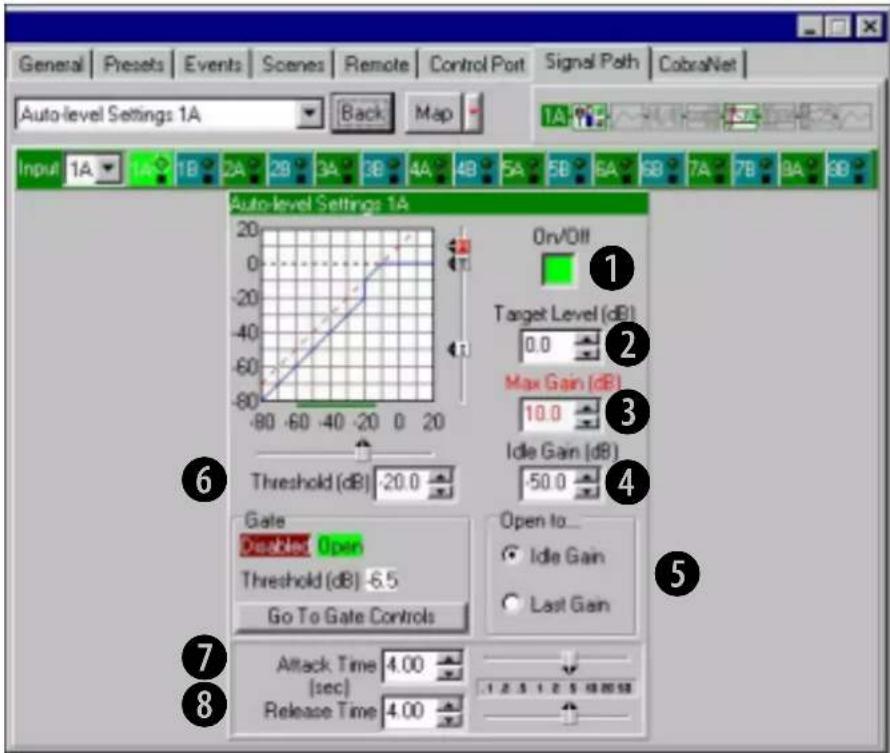
The Auto-leveler works in tandem with the Input Gate to compensate for long-term average input levels that vary over time. When the Auto-leveler is enabled, the open state gain of the corresponding Input Gate, normally 0dB, is adjusted dynamically to achieve a desired average output level. The Auto-Leveller's affect on input gain is metered by the Input Dynamic Cut/Boost Meter.
In the example above, the Threshold is set to -20db and the autoleveller allows the input signal to pass unaffected at levels below the Threshold. At input signals above the Threshold, the autoleveller adds gain to try and adjust the signal to the 0db Target Level. At input signal levels above 0db, the signal is clamped to 0db.
Eight parameters control this feature:
① On/Off
Turns this feature on or off
Processing Functions Auto-leveler

② Target Level
Sets the desired average output level. The Auto-leveler will expand input signals below this level and compress input signals above this level.
Control range is from -100 to +20dB in 0.5dB steps.
③ Max Gain
Sets the maximum gain through the Auto-Leveler. This feature can prevent 'runaway' from occurring during periods of very low signal level.
Control range is from -100 to +20dB in 0.5dB steps.
④ Idle Gain
Sets the initial Gate gain when the Auto-Leveler mode is set to "Open to Idle Gain". Using the "Idle Gain" setting can provide a smoother transition from very soft to very loud input program.
Control range is from -100 to +20dB in 0.5dB steps.
⑤ Open to...
When set to “Last Gain” the Gate opens to the last gain computed by the Auto-Leveler. In “Idle Gain” position, the Gate opens to a potentially safer “Idle Gain” setting.
⑥ Threshold
Sets the input level below which the Auto-Leveler action will be inhibited. This allows the Auto-Leveler to suspend gain changes during quiet passages and, along with Max Gain, prevent excessive system gain.
Control range is from -100 to +20dB in 0.5dB steps.
⑦ Attack Time
Sets the time required for the Auto-Leveler to expand its gain by 20dB.
Control range is 0.1 to 60 seconds in 0.1 second steps.
⑧ Release Time
Sets the time required for the Auto-Leveler to compress its gain by 20dB.
Control range is 0.1 to 60 seconds in 0.1 second steps.
Processing Functions Input Compressor
Input Compressor
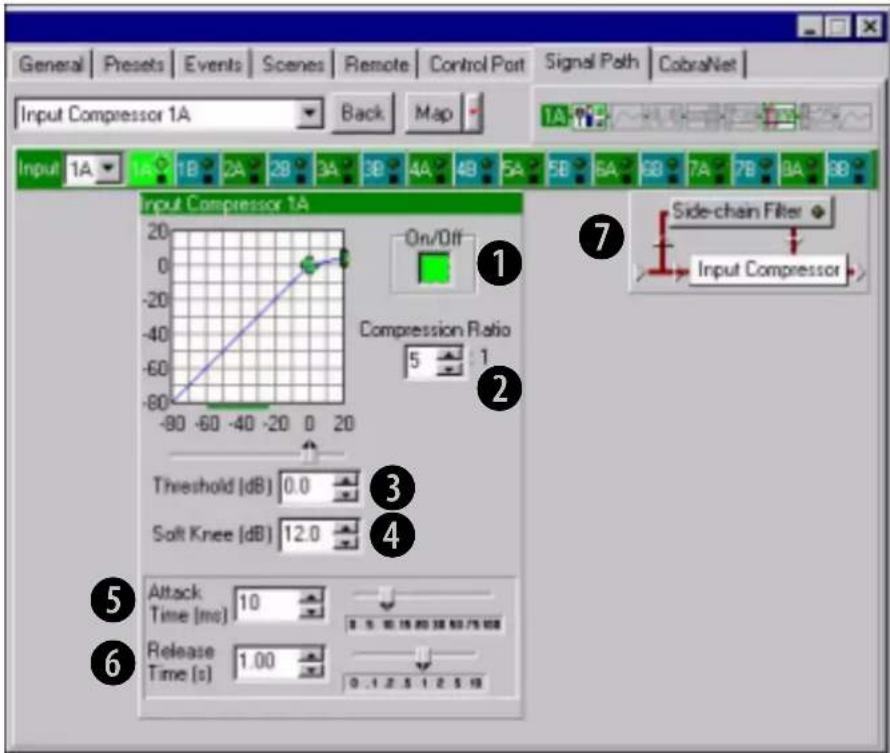
The input compressor provides a means for controlling the dynamic range of input signals. It is a feed-forward type, which performs the compression after the Input Level Meter. The Input Compressor's effect on input gain is metered by the Input Dynamic Cut/Boost Meter.
Seven parameters control this feature:
① On/Off
Turns this feature on or off
② Compression Ratio
Determines how many dB the input level must change for a 1dB change in output level. Dynamic variations in the input signal will be reduced by a factor equal to the compression ratio.
Control range is 2:1 to 32:1
③ Threshold
Specifies the average signal level (after side-chain processing) above which the compressor will begin to reduce gain.
Control range is from -80 to +20dB in 1dB steps
Processing Functions Input Compressor
④ Soft Knee (Width)
Sets a range in dB around the actual threshold through which the compressor gain is gradually modified from unity to the final compressed gain.
Control range is from 0 dB to +20dB in 0.5dB steps.
⑤ Attack Time
Sets the time required for the Compressor to decrease its gain by 20 dB.
Control range is from 1.0 to 100 milliseconds in 1 millisecond increments
⑥ Release Time
Sets the time required for the Compressor to increase its gain by 20 dB.
Control range is from 0.1 to 10 seconds in 10 millisecond increments
⑦ Side-chain Filter
The Compressor Key Filter operates as a 'side-chain' processor to filter the Control Key signal used to trigger the compressor. Its output is not directly in the signal path, and only affects the sensitivity of the Compressor Threshold versus frequency.
Processing Functions Auto-Mixer
Automixer
Automatic mixers allow 'hands-free' mixing that minimises many of the undesirable effects of using multiple microphones. Applications such as conference rooms, training rooms and boardrooms typically implement many microphones for individual speakers. Simultaneously mixing all microphones with acceptable gain before feedback manually is not possible.
The BSS PS-8810 implements three automixing functions to address this situation: Priority Ducking, NOM Attenuation and Adaptive Gating.
Each of the sixteen Input Processing Sections can be grouped into any of 32 Auto-Mix Groups. In addition to the Group assignment, each Input Section includes a separate 'Enable' control. This controls whether the respective channel participates in its assigned groups AutoMixing functions. There are group Automixing controls and individual Input Processing Section controls. Automixing's effect on input gain is metered by the Input Dynamic Cut/Boost Meter.
Priority Ducking
Enforces a priority order of open microphones such that high-priority inputs duck (attenuate) lower-priority inputs. Additionally, a maximum number of equal-priority open microphones may be specified. Each input can be assigned a Priority from 1 (highest) to 8 (lowest). When an input gate opens, it is allowed to pass according to the priority that has been assigned and is dependent upon the other open inputs within its group.
Keeping the number of open microphones to a minimum reduces background noise while allowing a higher gain before feedback for improved intelligibility.
Input gates must be enabled for all inputs participating in Priority Ducking within an Automix Group.
If an input belongs to more than one Auto-Mix Group, it MUST be the highest priority in all of the groups in which it participates.
Processing Functions Auto-Mixer
Automixing Group Controls
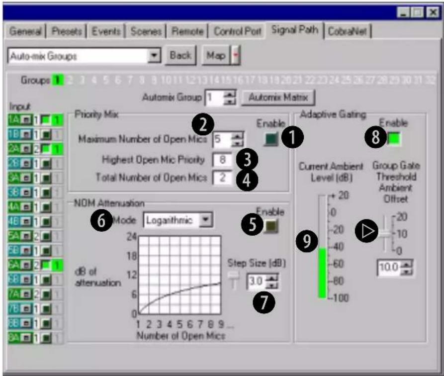
There are two group controls and two group indicators for this feature:
① Priority Mix Enable
Turns Ducking Priority Mix on and off for the automix group
② Max Number of Open Mics
Sets the max number of open mics within the automix group. A last-in, first-out algorithm is used to determine which mics are ducked
③ Highest Open Mic Priority Indicator
Shows the highest priority level for all open mics within the automix group
④ Total Number of Open Mics Indicator
Indicates the total number of presently open mics within the automix group
Processing Functions Auto-Mixer
NOM Attenuation
NOM (Number of Open Mics) Attenuation reduces overall system gain as the number of open mics increases beyond one for improved gain before feedback.
There are three group controls for this feature:
⑤ Enable
Turns NOM Attenuation on and off within an automix group
⑥ Mode
Sets the attenuation algorithm to linear or logarithmic. In linear mode, each open mic beyond one will cause all inputs in the auto-mix group to be attenuated by an amount equal to the Attenuation Step Size, defined below.
logarithmic mode: the attenuation per open mic will decrease as more mics open. Logarithmic mode with Attenuation Step Size of 3dB emulates 'classic' NOM attenuation schemes
Linear mode: allows each individual mic to use a higher nominal gain by more aggressively attenuating as more mics open.
⑦ Step Size
With NOM Attenuation mode, determines the attenuation as a function of the number of open mics in the auto-mix group. In linear mode, each open mic beyond one increases the attenuation by this amount.
Control range is from 0.5 to 3dB in 0.5dB steps.
Adaptive Gating
Adaptive Gating dynamically modifies the Input Gate thresholds in the auto-mix group as a function of the ambient level in the room. The ambient level is computed as the weighted average of the closed mic input levels. The weighted average makes it possible to compensate for mic locations with different ambient levels.
There are two group controls, one group meter, and one individual input control for this feature:
⑧ Enable
Turns Adaptive Gating on and off for an automix group
Processing Functions Auto-Mixer

Ambient Level Meter
Indicates the calculated ambient level for the automix group.

Group Gate Threshold Ambient Offset
Sets the amount above the calculated ambient level for the gate threshold for all inputs participating in the automix group.
- For inputs with ambient weighting factors equal to zero or one, the actual gate threshold will be offset from the calculated ambient level by this amount.
- For inputs with ambient weighting factors between zero and one, the offset is expanded prior to adding it to the calculated ambient level - the smaller the weighting factor, the larger the expansion.
Control range is from 0 to 20dB in 0.5dB steps

Individual Control:
Ambience Weighting
The weighting factor used in the ambient level calculation for each input. This control should be set to 1 with the following two exceptions:
- To exclude the mic from the ambient level calculation, set the weighting factor to zero
- To compensate for a mic in a relatively noisy location set the weighting factor to a value between zero and one. Control range is from 0 to 1 in 0.1 step increments.
Processing Functions Auto-Mixer
Automix Matrix
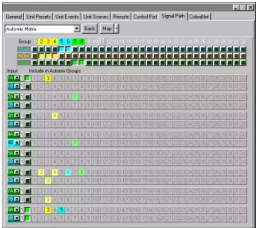
Auto-mix Matrix
Accessed by pressing the Auto-mix Martian button in the Signal Path window. This window is an interactive overview of all the possible automix routings assignments and priorities. There are three main automix functions; Ducking, NOM and Adaptive Gating and these work as a group.
Ducking is based upon the 16 inputs, these inputs are assigned a priority (1 being the highest) and involves cutting an input based upon a gate being open for a higher priority. NOM is a reduction based upon how many open mics are in the group and Adaptive Gating moves the threshold of the gate based upon an external source.
Colours denote the type of function assigned from the input to the automix group, Blue=Ducking, Yellow=NOM and Green=Adaptive Gating. Assignments set up in the matrix take on the colour of the active function and, if two or more functions are set up then the colour will change to red. If the individual input enable switches are off then the colours become faint and, if the group functions are disabled then the numbers become white although the assignment remains.
The group function is enabled by clicking on the rows (either Duck, Nom or Gate) at the top of the window. Clicking on the Group row numbers at the very top of the window accesses the group controls window for that group number.
Processing Functions Auto-Mixer
Automixing
Individual
Controls
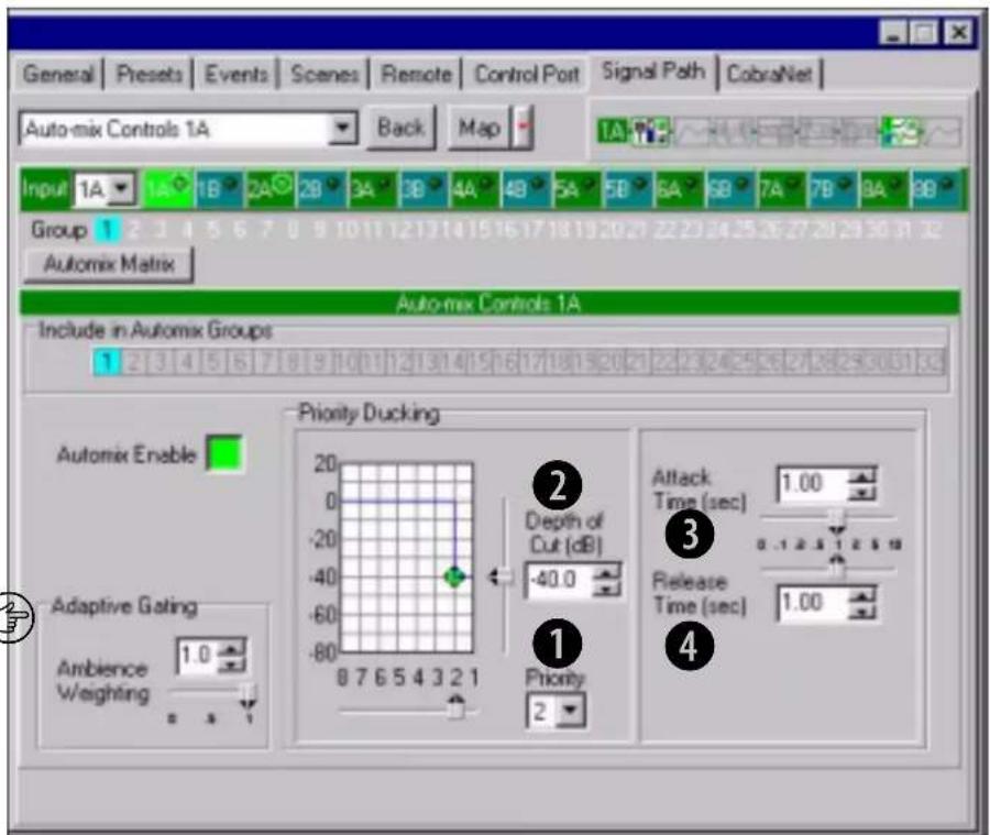
There are four individual Input controls:
① Priority
Assigns a relative priority to each channel.
Control range is 1 to 8; where 1 is the highest priority and 8 is the lowest priority
② Depth of Cut
Sets the 'ducked' mic gain.
Control range is from -100 to 0 in 0.5dB steps
③ Attack Time
Sets the time required for Priority Ducking to attenuate the mic gain by 20dB.
Control range is from 10 milliseconds to 10 seconds in 10 millisecond steps
④ Release Time
Sets the time required for Priority Ducking to increase the mic gain by 20dB.
Control range is from 10 milliseconds to 10 seconds in 10 millisecond steps
Processing Functions Solo/Mute
Solo/Mute Solo/Mute
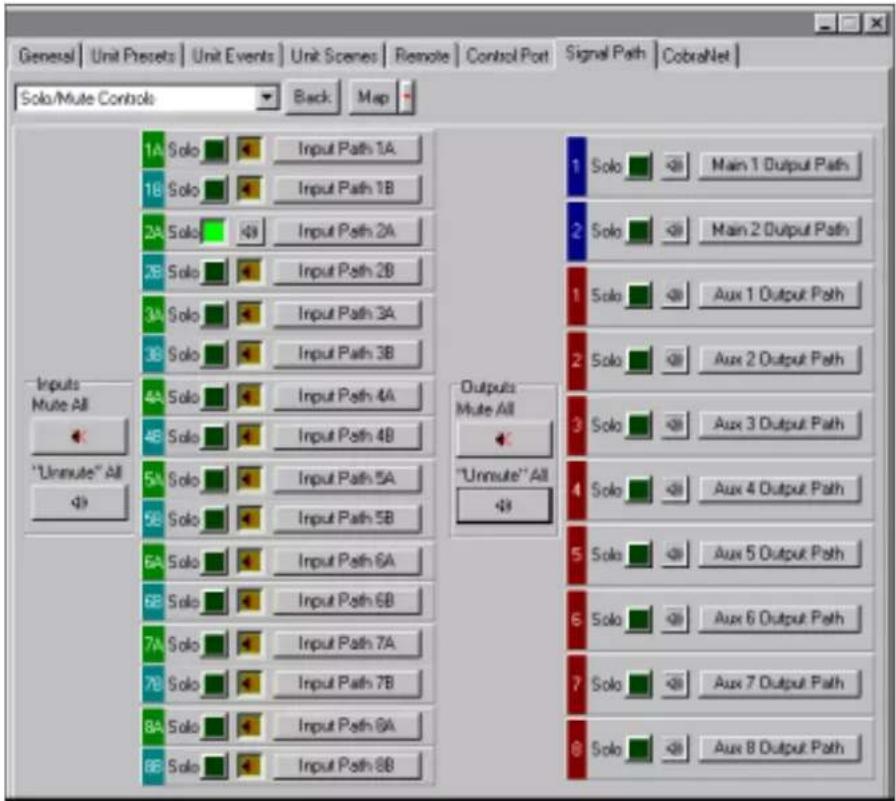
The status of the Input and Output channel mutes and solos can all be monitored by pressing the "Solo/Mute" button above the main Signal Path window. From here individual channels can be soloed for preview purposes and muted equally, all solos and mutes can be switched in or out for the Inputs and Outputs separately.
Processing Functions Input/Output Matrix
Input/Output Matrix
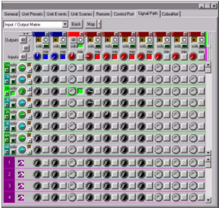
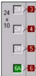
The matrix allows routing, soloing, muting, gain adjustment and polarity inversion of the available audio channels through the PS-8810. This panel is accessed by clicking on the grey area of the 24x10 block in the middle of the Signal Path window.
Individual input channels can be assigned exclusively to any other single output channel or, can be crossmixed through the 24:1 mixer using the level control associated with the routing position in the matrix. Individual channels can be soloed to check signal integrity/level and furthermore, any input channel can be soloed together with any output channel for source/destination assessment. Alternatively, routing can be handed back to the 24:1 matrix by pressing the 'Mix' button associated with the output channel that has had an exclusive assignment applied, this disconnects the exclusive routing.
The fact that the same signal input is routed to the two A/B Input Processing Sections makes it possible to process each input two different ways. For example, it is possible to route a single input (or set of inputs) to both a PA system and also a record feed, in this case use the signal from Input Processing Section A for the PA
Processing Functions Input/Output Matrix
system and the signal from Input Processing Section B for recording.
This panel at top left of the window has two functions; firstly it acts as the overall mute cancel control, the top speaker icon unmuting all the outputs, the bottom all the inputs and the middle both the inputs and outputs simultaneously. Note that this clears any solo assignments made for the selected channels.

Secondly, the small box with two arrows is the Matrix window expand/compress button. With all the controls displayed for all the channels this window can only be shown in full on a very high resolution screen (usefully 19" or above monitor). In order to give access to all the channel controls on smaller screens the window can be compressed to a more standard size by pressing this button.

In this situation an extra scroll bar control is displayed to the right of the output channel controls, this is the default on opening the window. Moving this slider alters the ratio of analogue channels (green) that are displayed to the number of CobraNet channels (pink). If the window is in its full size mode then this control is not available and, the scrollbar for the analogue channels changes to a green bar and a pink bar for the CobraNet channels.
The top row controls are for the output channels. The first two blue topped columns are the Main outputs and the red are the Aux outputs. These all have the same controls which include a mute button (speaker icon), polarity switch (+ or - button), a solo control (green for solo active), a gain control and a 'Mix' button that reassigns any exclusive routings back to the 24:1 mixer level controls. There is also a small signal indication meter. Clicking on the small box in the coloured column header will leave the Matrix and open the associated Output Path window.
The input channel controls are on the left of the Matrix and offer a solo, input gain level adjustment, polarity switch and a mute (shown by a small musical note symbol here). As usual the A and B input processing paths are denoted by blue and green colouring. Clicking in the small box in these coloured areas opens the Input Path window linked to that channel.
Processing Functions Input/Output Matrix
The CobraNet input channels have the CobraNet logo and are coloured pink. There are no overall channel controls available to these inputs.
The crosspoint controls in the Matrix itself enable an amount of signal to be routed using the black level control - control range is from "Off" to +20dB. Exclusive assignment of a particular input to output is attained by pressing the button at the crosspoint between the required channels. In this situation the level controls for all inputs in that output channel become greyed out and are inactive.
Processing Functions Output Path

Output Path
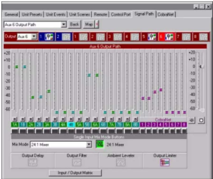
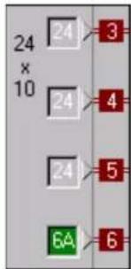
This panel is either accessed by clicking on one of the numbers written in the 24x10 area or by clicking on the Output fader/mute/polarity icon at the end of the Output processing section.
In addition to the output of each of the sixteen Input Processing Sections, the eight CobraNet Inputs are fed to the Matrix Mixer, providing a 24 Input by 10 Output fully independent crosspoint mix as controlled by the Input/Output Matrix. Each of the ten Output Processing Sections has independent fader control of all of the inputs to the selected output, i.e. a 24:1 mixer, as shown above.
The Mix Mode drop down box is used for selecting exclusive assignments between a particular input and output. This function is repeated with the Single Input Mix Mode Buttons or the routing can be reassigned to the 24:1 mixer.
The selected output channel displays the status of the Output Processing Section objects and their parameters can be accessed by clicking on these icons. There is also a button to quickly access the Input/Output Matrix for further routing options.
Processing Functions Output Section
Output Section Output Processing Sections
Each of the ten Outputs, (two 'Main' and eight 'AUX'), have independent Output Processing Sections to allow control of the mixed output. Output Processing functions include delay, filters, ambient leveler, limiter, fader, mute, and polarity inverter.
Output Delay
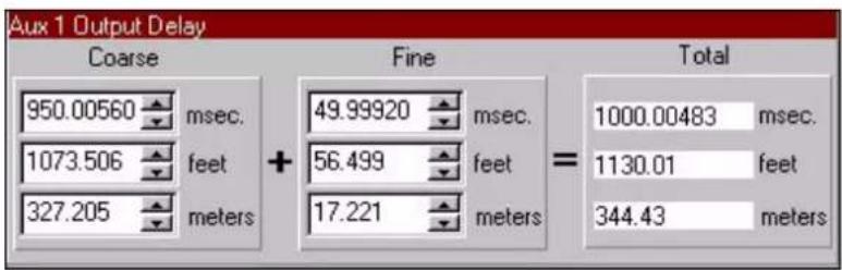
Output Signal Delay can be set for each Output Processing Section. This delay is especially useful in loudspeaker array alignment, where the crossovers, mix, and other processing is complete and the loudspeaker needs to be aligned to the system.
The inherent delays of the various input signals should be corrected by the delay in the Input Processing Section.
Delay is displayed by IQ for Windows software in milliseconds, feet, and meters. Available delay for each Output Processing Section is up to 2 seconds in 20 microsecond steps (1/4 inch).
Output Filters

These filters are identical to the Input Filters, please read the section on Input Filters for more information. As was the case with the Input Filters, the two DSP's that process the outputs have a finite amount of processing capability. Each of the DSP's can provide up to 64 filters, with Main 1 and AUX 1-4 processed by one DSP and Main 2 and AUX 5-8 processed by the other. The CPU Utilization meters indicate how much DSP processing capability remains.
Processing Functions Ambient Leveler

Ambient
Leveler
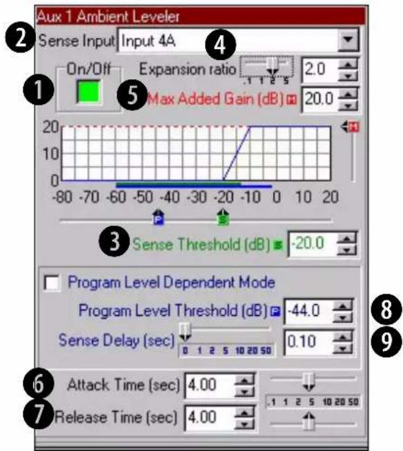
The Ambient-Leveler expands the output channel gain to compensate for a sensed ambient level. The ambient level can be sensed from any of the sixteen Input Processing Sections, or the computed ambient level from one of the 32 auto-mix groups. This feature allows the BSS PS-8810 to maintain optimum signal to noise and intelligibility in environments with varying background noise.
The software graphically displays the gain function, with line meters underneath the graph displaying the Input Ambient Sense level (green) and the Output Signal Level (blue).
Seven parameters control this feature:
① On/Off
Turns this feature on or off
② Sense Input
Determines the source for the ambient level that will do the adjustment
③ Sense Threshold
Sets a level for the ambient sensor input threshold. The Ambient-Leveler expansion will be inhibited for input levels below this threshold. This action allows the Ambient-Leveler to suspend gain changes when the ambient level is low and, along with Max
Processing Functions Ambient Leveler

Added Gain, prevent excessive system gain.
Control range is from -80 dB to +20 dB in 0.5dB steps
④ Expansion Ratio
Determines how much the gain of the output channel will increase for every increase in the ambient signal level above the Threshold setting. A 4:1 Expansion Ratio setting will raise the output gain 4dB for every 1dB that the ambient signal increases.
Control range is from 0.1:1 to 5:1
⑤ Max Added Gain
Sets the maximum increase in gain through the Ambient-Leveler. Control range is from 0dB to +20 dB in 0.5dB steps
⑥ Attack Time
Sets the time required for the Auto-Leveler to expand its gain by 20dB.
Control range is from 0.1 to 60 seconds in 0.1 second steps
⑦ Release Time
Sets the time required for the Auto-Leveler to compress its gain by 20 dB.
Control range is from 0.1 to 60 seconds in 0.1 second steps
Program Level Dependent Mode
Allows the Ambient-Leveler expansion to be inhibited when the actual output Program level is above a prescribed level. This mode prevents program material 'feed-through' from artificially increasing the apparent ambient level.
⑧ Program Level Threshold
Sets the output program level threshold above which Ambient-Leveling will be inhibited when in Program Level Dependent mode.
Control range is from -80 to +20dB in 0.5dB steps
⑨ Sense Delay
Sets the delay after the output program level falls below the Program Level Threshold before the Ambient Leveling begins. Control range is 0 to 60 seconds in 0.1 second increments
Processing Functions Output Limiter
Output Limiter
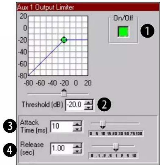
The Output Limiter function provides a means of directly monitoring and controlling peak output level. It is especially valuable for the protection of amplifiers, loudspeakers and other audio equipment. The Output Limiter operates similar to a compressor with an infinite compression ratio, preventing the output level from exceeding the specified Threshold.
Four parameters control this feature:
① On/Off
Turns this feature on or off
② Threshold
Used to set the peak signal level above which compression occurs.
Control range is from -80 to +20dB in 0.5dB steps
③ Attack Time
Sets the time required for the Limiter to decrease its gain by 20dB.
Control range is from 1 to 100 milliseconds in 1 millisecond steps
④ Release Time
Determines how long it takes for the gain to return to normal when the level drops below the Threshold.
Control range is from 10 milliseconds to 10 seconds in 10 millisecond steps
Processing Functions Output Select
Output Select
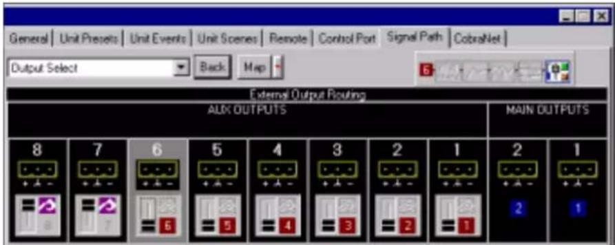
Each AUX output is individually switchable via the AUX Output Select switches, accessed by clicking on the black Aux boxes in the Signal Path window. The eight rear panel AUX outputs can either be the output of an Output Processing Section or they can be fed from a CobraNet Output.
The output of the two Main Output Processing Sections goes directly to the analogue output drivers that provide the signal on the rear panel of the unit.
Clicking on one of the Aux output representations displays an overview of that channels current output processing configuration. The Main Outputs graphics have no function and are purely for display purposes.
12.0 Presets
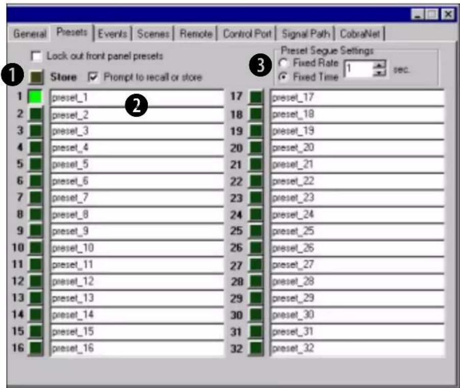
The BSS PS-8810 has the ability to reconfigure itself with a single command. Thirty-two 'Presets' can be stored and recalled via a variety of means including the front panel, via a Control Port Input, an IR command, or a scheduled 'Event'.
① For a Preset to be stored, all of the individual controls needs to be set up using IQ Win whilst on-line to the PS-8810, then the 'Store' button pressed and a Preset selected.
To ensure that settings are not inadvertently lost due to selection of a Preset instead of storage of a Preset, the "Prompt to recall or store" checkbox allows a query window to display whenever a Preset button is pressed in order to ensure the intent of the user.
② Each Preset has a 32 character user definable label.
③ Preset Segue This enables smooth level transitions between Presets. When a Preset is selected, all of the fader settings are changed at a rate that is determined by the 'Preset Segue Settings' box. The rate of change can be either a 'Fixed Time' that is selectable from 0 second to 255 seconds or a 'Fixed Rate' that goes from 0.5dB/sec to 40dB/sec.
13.0 Scenes
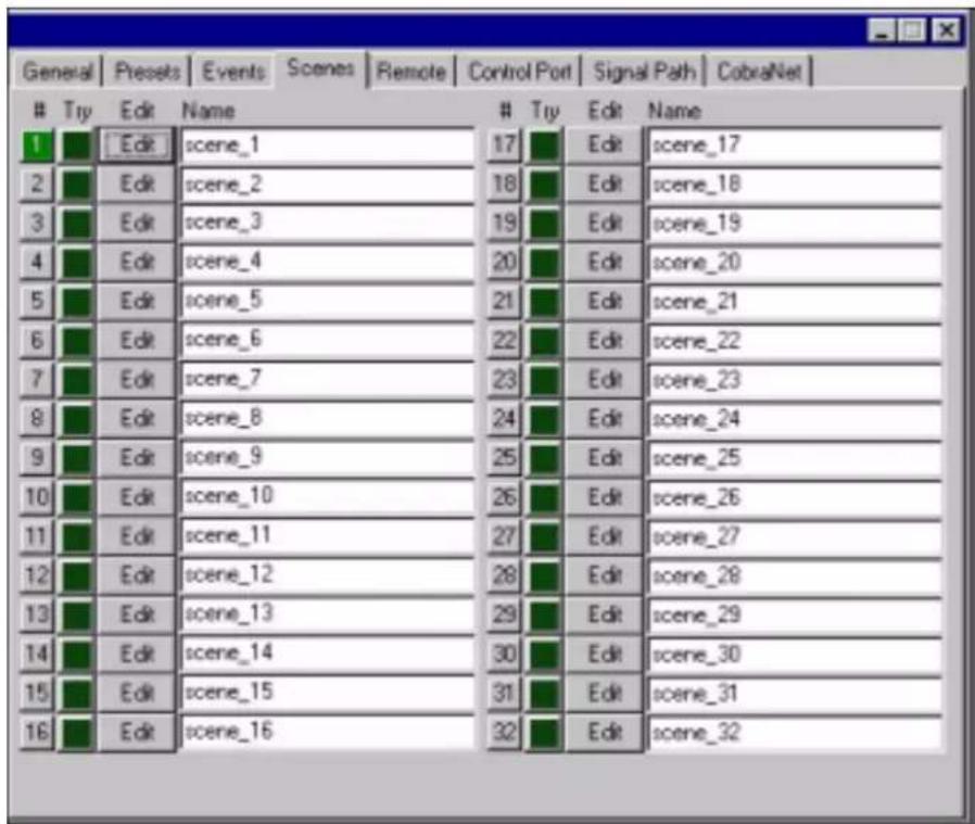
There are times when only a few objects' settings need to be changed and this is the function of 'Scenes'. PS-8810 Scenes allow up to 50 objects to be grouped together and changed to a specific state with a single command. Like Presets, Scenes can be changed from the front panel, a Control Port Input, an IR command, or a scheduled 'Event'.
Each Scene has a 32 character label associated with it and the Scene Editor allows the objects to be selected and configured for each Scene.
Note: These 'unit' Scenes should not be confused with the IQ Win equivalents that are saved as .SIQ files and are handled quite differently with a different scheduler.
Scenes
Scene Editor
2
3
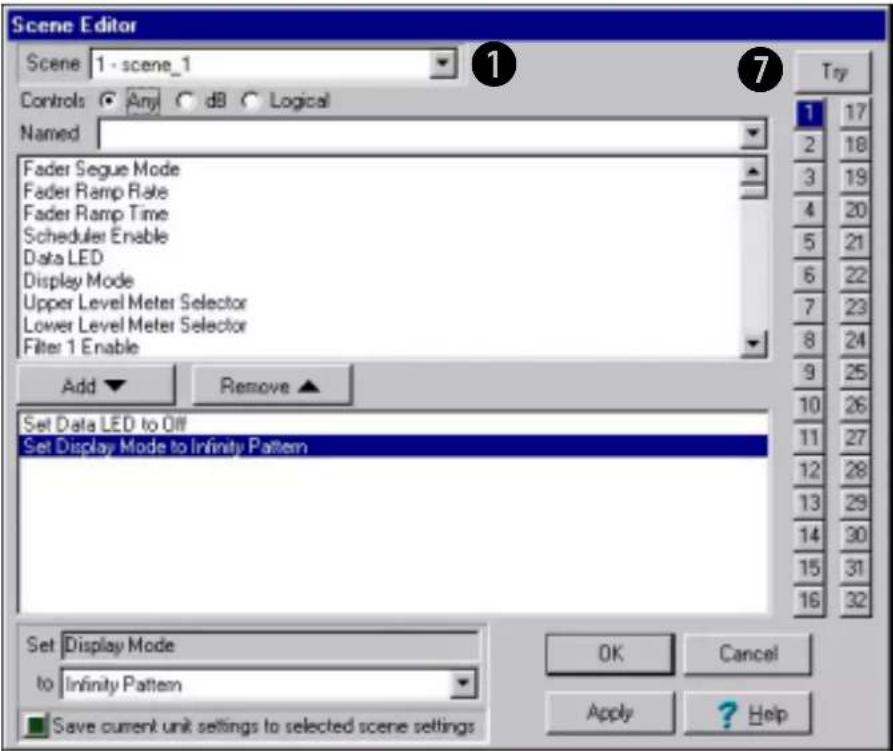
4
5
6
① Select the Scene to be edited in the 'Scene' box at top, or click on one of the 32 buttons located at the right of the screen.
② The 'Controls' selector allows the type of parameters to be chosen to be narrowed down by selecting either 'dB' or 'Logical'.
③ Use the 'Named' box to type in all, or part of, the name of the control you wish to add to the Scene. The selection of available parameters will change as you type, if the selection is incorrect delete all the text and start again to bring back the complete listing.
④ The 'Add' and 'Remove' buttons allow you to choose which parameters are to be included in the Scene.
⑤ Select one of the parameters in the bottom box and its settings will become available to change.
⑥ The "Save current unit settings to selected scene settings" enables the chosen parameters to have their settings taken from the actual settings for those parameters that are set in the PS-8810. This solves the problem of having to set up those controls to manually reflect the values found in the PS-8810.
⑦ The 'Try' button allows the Scene to be simulated to ensure that the settings are those that are desired.
14.0 Events Scheduler
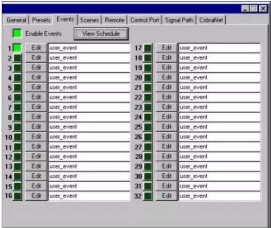
Different configurations can be triggered at particular times. The BSS PS-8810 has an internal real time clock that can be used to setup a schedule for recalling Presets or Scenes. By using the 'Event Scheduler' to recall unit settings at certain times, the unit can be used in a variety of different ways.
The internal clock has a 'keep alive' capacitor that allows the unit to be unpowered for up to 45 days without losing the current date and time.
Each Event can be enabled individually and the entire Event Scheduler can be enabled, allowing the scheduler to be turned off without having to switch individual Events off. Each Event has its own label and the 32 Events can be individually set to recall a Preset or Scene in either a one time or periodic mode.
Events Scheduler
One Time Events
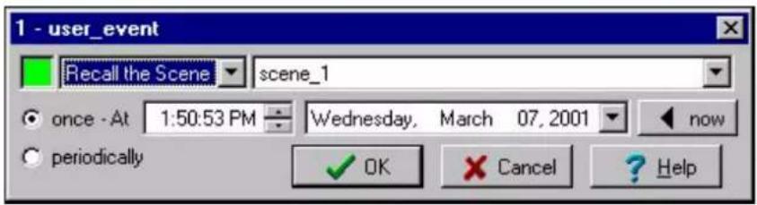
An Event can be scheduled to occur only once, and the time of the Event can be programmed by choosing 'once'. The exact time of the Event can then be set.
Periodic Events
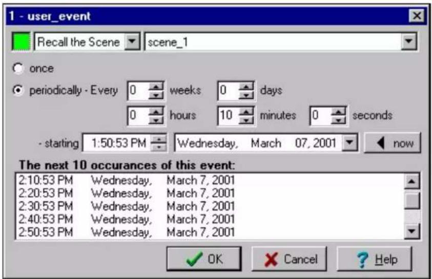
If an Event is required at a set rate, the Event editor allows the programming the Event at periodic intervals. Each Event can have its own repetition rate and starting time, independent of any other. The Event schedule window shows the next 10 occurrences of the Event. By using multiple Events that are interleaved, a pattern of Events can allow switching between several setups in a regular timed fashion.
Events Scheduler
Schedule
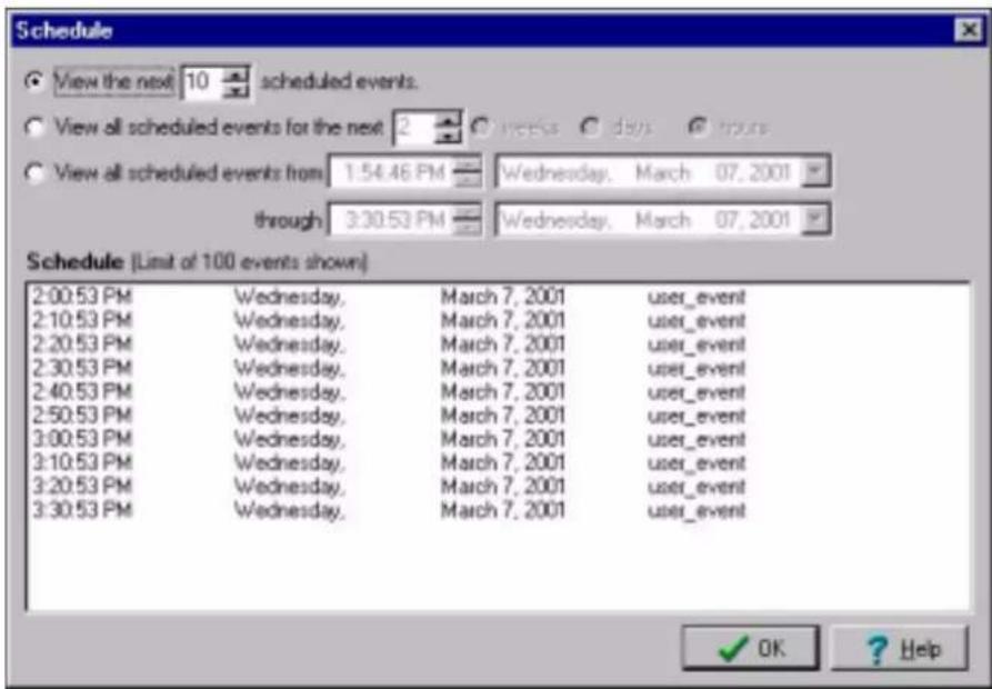
The main Event 'View Schedule' button allows viewing of all of the enabled Events for a defined period of time. This ensures that the desired sequence of periodic Events are occurring at the desired times.
CobraNet®

15.0 CobraNet ^®
Explanation
CobraNet is a technology developed by Peak Audio, Inc. that allows real time digital audio to be distributed over standard Fast (100Mb) Ethernet hardware. CobraNet allows the PS-8810C to not only have analogue inputs and outputs, but also to provide 8 digital Inputs and 8 digital Outputs from a CobraNet network. These additional Inputs and Outputs allow enhanced routing and processing capabilities, including the passing of audio channels to other PS8810's to create larger mixing and processing structures.
Transmission of digital audio via CobraNet is accomplished through 'Bundles' and 'Slots'. Bundles are Ethernet packets that contain up to eight digital audio channels, called 'Slots'. Each digital audio channel is assigned a position (1-8) within the Bundle, hence the name Slot. The Bundle is then assigned a unique number that indicates how it will be transmitted on the CobraNet network. A receiver merely needs to select the Bundle number to receive the audio.
Bundles can be either multicast or unicast. Multicast bundles are sent to all CobraNet network devices, while unicast bundles are sent to one, and only one, CobraNet network device. Through the use of Fast Ethernet switches, unicast transmission of bundles can greatly increase the number of bundles that can be present on a CobraNet network since the bundles only go to the device that is addressed. Since each device can send and receive four bundles (i.e. up to 32 channels), great flexibility is allowed in the routing of audio over the network. Assignment of bundles as multicast or unicast is done through the assignment of the bundle number. Bundles with numbers 1-255 are always multicast, while bundles 256-65,279 are designated as unicast. Bundle assignments need to be unique, with only one CobraNet transmitter allowed per bundle.
The coordination, i.e. clock master, of the CobraNet network is the function of the 'Conductor'. The 'Conductor Priority' is set in each device and decides which unit will be the Conductor. If the Conductor is removed from the CobraNet network for any reason, the remaining devices decide who becomes the Conductor based on a numerical hierarchy, i.e. priority '0'=never and '255'=always. The PS-8810 is set as '32' as a default.
The Conductor is responsible for ensuring that all devices on the CobraNet network transmit their bundles in a coordinated way.
The Conductor recognizes each device on the network and assigns a transmission position for each bundle of each device.
In addition the Conductor sends master clock to each device to ensure that all audio is synchronous. Like a conductor of an orchestra, the Conductor signals the beginning of a synchronous transmission cycle, and then each device sends its bundle(s) in lock step. This occurs 750 times a second, with each audio channel having 64 samples of 48KHz audio. Each audio channel can be sent as 16, 20, or 24 bit samples. if 24bit audio is used then a bundle will be reduced to 7 channels. There is a fixed latency of 5.33ms.
CobraNet networks utilize Fast (100Mb) Ethernet hardware and can use either repeater hubs or switches. A repeater hub is a device that takes the data that comes into each port, and sends it back out on all ports except the port in came in on. As a result, only multicast bundles can be used in repeater hub networks and these need to be limited to 8 bundles per network.
On the other hand, switches are much more efficient, in that they examine the destination address of each packet of data received on each port, then switch that data to the particular recipient of that packet. Unicast bundles exploit this feature to minimize the audio traffic on the CobraNet network. The result is that an almost limitless number of unicast bundles can be on a switched CobraNet network. Multicast bundles are allowed on a switched network, but they must be used with care.
Peak recommends that not more than four multicast bundles be used in a switched CobraNet network. Peak also advise not to mix ordinary computer data on a repeater hub network, as this could result in dropout in the audio. In switched CobraNet networks, coexistence of CobraNet audio and ordinary computer data is possible, because there are no collisions with the audio.
If there are only two PS-8810 units involved in a CobraNet network these can be connected using CAT 5 crossover cables.
More information:
www.pekaudio.com
www.iqaudiosystems.com
Setup
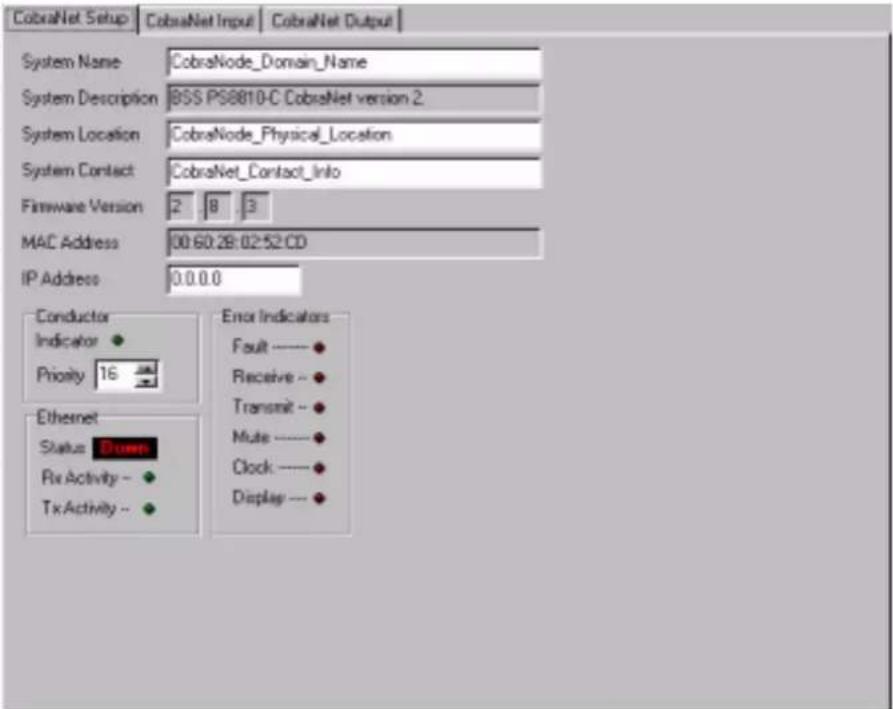
The CobraNet Setup tab allows an overall control of the PS-8810-C's CobraNet functions.
Several labels and information are available:
① System Name
This user defined label indicates the name of the particular PS-8810C
② System Description
This label is embedded in the CobraNode and indicates the manufacturer and description of the CobraNet device
③ System Location
Used to describe the location of the CobraNet device
④ System Contact
A label that tells who to contact in the event of a problem
⑤ Firmware Version
Indicates the CobraNode's firmware Protocol Version, Major Version, and Minor Version
⑥ MAC Address
The CobraNode's unique manufacturer hardware address.
6 IP Address
The Internet Protocol address that is assigned by the system integrator. Used as a standard part of ethernet networking transmission protocols and works much like a zip/postal code for the unit on the network.
⑧ Conductor
The CobraNet 'Setup' tab indicates information about the status of the Conductor. Each CobraNet device can be assigned its own Conductor 'Priority' which will be used to determine who will be the Conductor of the network. Conductor Priority values range from 0 to 255, with 0 being the lowest priority and 255 being the highest priority. A light indicates when the CobraNet device is the Conductor of the system. The PS-8810 defaults to 32.
⑨ Status indicators
There are a number of status and error indicators for the CobraNet network.
The Ethernet 'Status' tells if the physical network is connected to the unit. The 'Rx Activity' and 'Tx Activity' lights tell if there is incoming or outgoing Ethernet activity.
The Error Indicators are:
- Fault: An overall fault in the CobraNet network
- Receive: An error on received CobraNet Bundles
- Transmit: An error on transmitted CobraNet Bundles
- Mute: An audio output may be corrupt
- Clock: Fault or lost contact with the CobraNet network
- Display: Encountered an unexpected error
Input
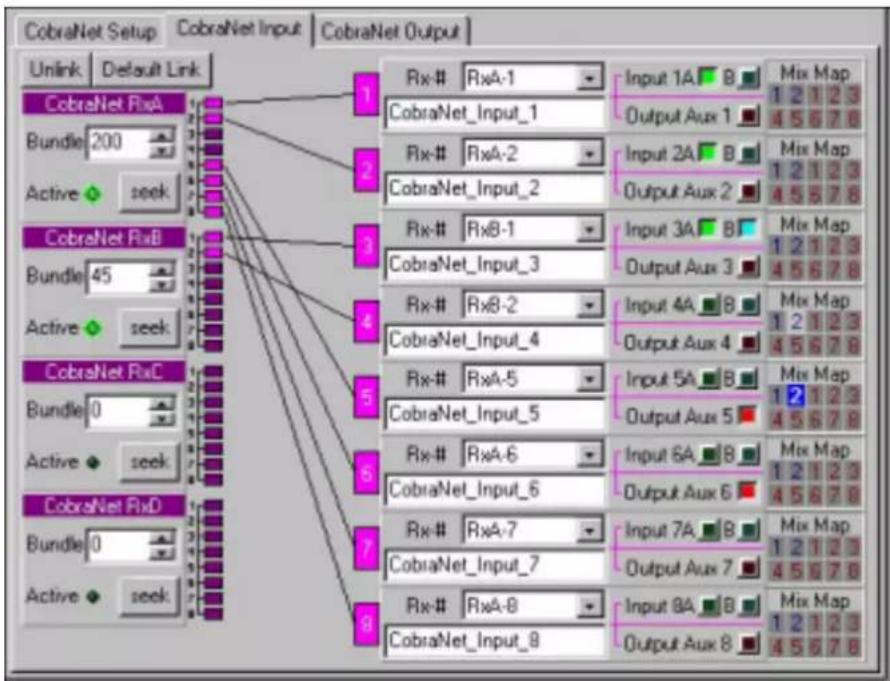
flowchart
graph TD
    A["CobraNet Setup"] --> B["Unlink"]
    A --> C["Default Link"]
    D["CobraNet RxA"] --> E["1"]
    D --> F["2"]
    D --> G["3"]
    D --> H["4"]
    D --> I["5"]
    D --> J["6"]
    D --> K["7"]
    D --> L["8"]
    M["CobraNet RxB"] --> N["1"]
    M --> O["2"]
    M --> P["3"]
    M --> Q["4"]
    M --> R["5"]
    M --> S["6"]
    M --> T["7"]
    M --> U["8"]
    V["CobraNet RxC"] --> W["1"]
    V --> X["2"]
    V --> Y["3"]
    V --> Z["4"]
    V --> AA["5"]
    V --> AB["6"]
    AC["CobraNet RxD"] --> AD["1"]
    AC --> AE["2"]
    AC --> AF["3"]
    AC --> AG["4"]
    AC --> AH["5"]
The PS-8810C can accept four Bundles from the CobraNet network and route the audio Slots of those Bundles into the processing and mixing of the unit. These four Bundles (RxA, RxB, RxC, and RxD), are assigned Bundle numbers by the Bundle window. If a transmitter is supplying audio on that Bundle, the Active lamp will light. The 'Seek' button allows scanning of the multicast Bundles (Bundles 1-255) to see if any of the Bundles have audio data on them. If audio is detected on any of those Bundles, the Bundle number will stop at that point.
The individual audio Slots are assigned one of the eight CobraNet Inputs to the PS-8810C. Once the eight CobraNet Inputs have been assigned Bundles and Slots, they can be used by the unit for routing and processing. The CobraNet Inputs each have a unique label for identification and can be routed into the processor in several ways. The Input Processing Sections can accept either the analogue input or the CobraNet Input. In addition, a CobraNet Input can be routed directly to a corresponding AUX Output. Each of the 10 audio outputs have access to all eight CobraNet Inputs in their mix.
Links from any of the 8 bundle audio channels can be drawn by clicking on the pink boxes and dragging the wire to the chosen input. The 'Default Link' button sets up the first bundle to link to the respective 8 CobraNet inputs, while the 'Unlink' button removes all links.
Output
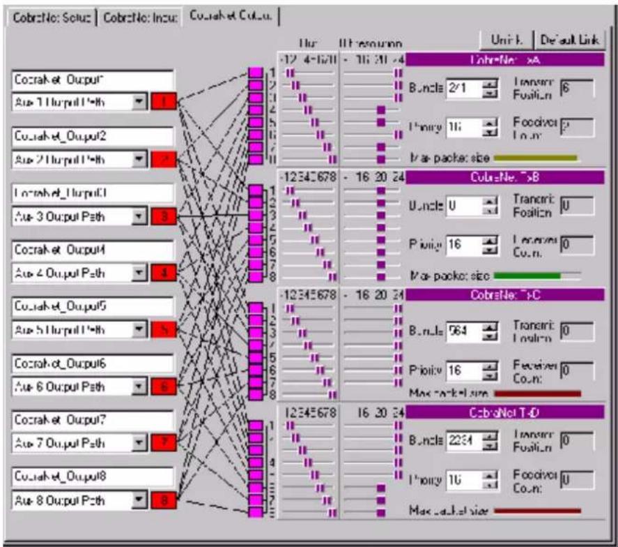
network
| Node | Value | |---|---| | Cocrak et Output | 1 | | Aue 1 Output1*th | 1 | | Cocrak et Output2 | 1 | | Aue 2 Output1*th | 1 | | Locrak et_Lurput1 | 3 | | Aue 3 Output Path | 3 | | Cocrak et Output4 | 4 | | Aue 4 Output Path | 4 | | Cocrak et_Output5 | 5 | | Aue 5 Output1*th | 5 | | Cocrak et_Output6 | 6 | | Aue 6 Output Path | 6 | | Cocrak et Output7 | 7 | | Aue 7 Output Path | 7 | | Cocrak et_Output8 | 8 | | Aue 8 Output Path | 8 | | Lnr - 4-1/21 - 16-20-24 | 12-34-5678 - 16-20-24 | | Lnr - 16-20-24 | 12-34-5678 - 16-20-24 | | Lnr - 16-20-24 | 12-34-5678 - 16-20-24 | | Lnr - 16-20-24 | 12-34-5678 - 16-16-24 | | Lnr - 16-20-24 | 12-34-5678 - 16-20-24 | | Lnr - 16-20-24 | 12-34-5678 - 16-20-24 | | Lnr - 16-20-24 | 12-34-5680 - 16-20-24 | | Lnr - 16-20-24 | 12-34-5680 - 16-20-24 | | Lnr - 16-20-24 | 12-34-5680 - 16-20-24 | | Lnr - 16-20-24 | 16-20-24 - 16-20-24 | | Lnr - 16-20-24 | 16-20-24 - 16-20-24 | | Lnr - 16-20-24 | 16-20-24 - 16-20-24 | | Lnr - 16-20-24 | 16-20/24 - 16/20/24 | | Lnr - 16/20/24 | 16/20/24 - 16/20/24 | | Lnr - 16/20/24 | 16/20/24 - 16/20/24 | | Lnr - 16/20/24 | 16/20/24 - 16/20/24 | | Lnr - 16/20/24 | 39/39/39/39/39/39/39/39/39/39/39/39/39/39/39/39/39/39/39/39/39/39/39/39/39/39/39/39/39/39/39/39/39/39/ |The PS-8810's eight CobraNet Outputs can be assigned to be transmitted on Slots in one of four CobraNet Bundles. The CobraNet Outputs can accept audio from either the corresponding 'B' Input Processing Section or the corresponding AUX Output Processing Section. Each of the eight CobraNet Outputs is then assigned a Bundle and Slot position. Unlike the CobraNet Inputs, the same CobraNet Output can go to more than one Bundle/Slot position.
The 'Unlink' Button allows all of the Bundle/Slot assignments to be disconnected, while the 'Default Link' Button allows assignment of CobraNet Output 1 to Slot 1 of each Bundle, CobraNet Output 2 to Slot 2 of each Bundle, and so forth.
Each Slot can be assigned either none, 16bit, 20bit, or 24bit resolution. Each Bundle is limited in the number of audio 'bits' that can be placed in a single Bundle and is a function of the maximum Ethernet data payload. The 'Max Packet Size' meter tracks how much room remains in the Bundle. Once the 'Max Packet Size' has been exceeded, additional data will not be allowed. As can be seen in the figure above, seven 24bit Slots are allowed in TxC with Slot 8 not active, while TxD allows all eight slots if three are 20bit.
The transmit Bundle is assigned in the window and a unique priority can also be assigned for each Bundle. This Bundle Priority is used by the Conductor to assign a transmit position on the CobraNet network. Audio Bundles are sent on the network in a synchronous fashion dictated by the Conductor. The Conductor assigns a position to each transmitting Bundle in the network based upon that Bundle's Priority. At the start of a synchronous cycle, the Conductor tells the highest priority Bundle to transmit, then each successive Bundle transmits based upon its assigned Position. The 'Receiver Count' for each Bundle tells how many receivers, i.e. other devices on the network, are listening to that Bundle. synchronous cycle, the Conductor tells the highest priority Bundle to transmit, then each successive Bundle transmits based upon its assigned Position. The 'Receiver Count' for each Bundle tells how many receivers, i.e. other devices on the network, are listening to that Bundle.
External Control
16.0 Infrared Remote Control
The BSS PS-8810 has the ability to use an IR remote control such as a programmable remote control device like the Philips Pronto to remotely control the unit.
The front panel of the PS-8810 has an IR receiver that can detect IR signals and switch objects based upon a particular received code. 64 available IR commands allow a variety of objects to be selected.
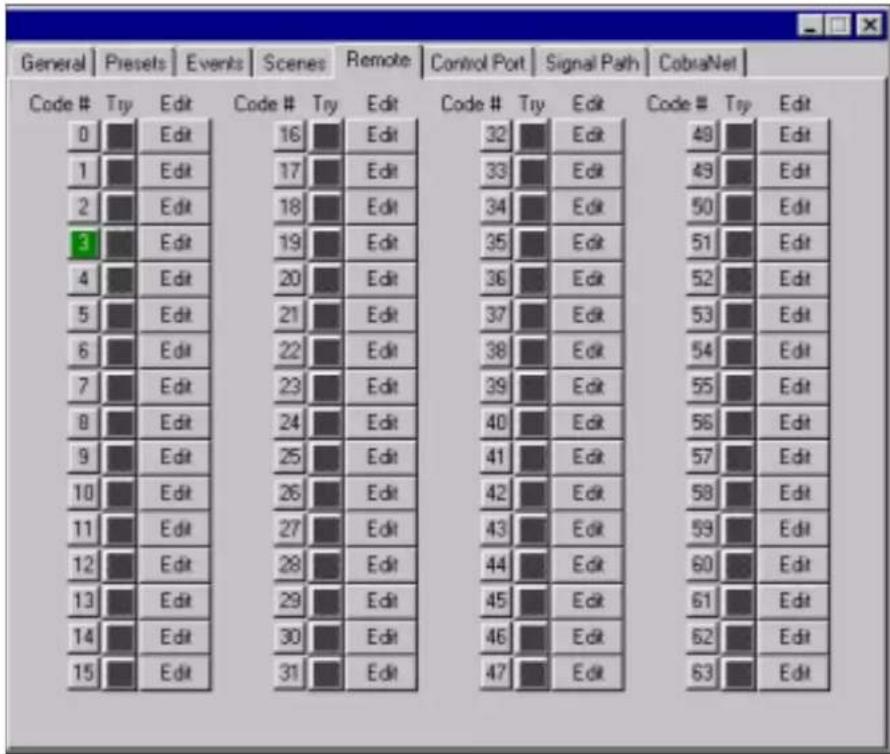
Infrared Remote Control IR Code Editor
IR Code Editor
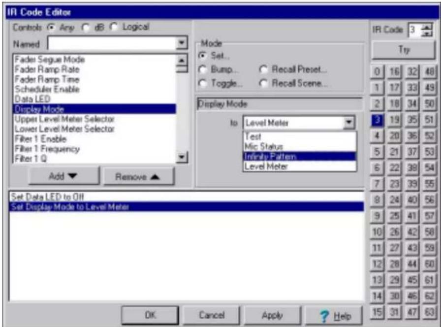
When a particular IR code's Edit button is pushed, the IR Code Editor window allows selection of objects for inclusion in that IR code. Each selected object can be edited for particular usage. The IR code can also be configured to recall a 'Preset' or a 'Scene'. As a setup tool, the 'Try' button allows the IR code configuration to be simulated to ensure that it acts as expected.
Infrared Remote Control Philips Pronto
Philips Pronto
The Philips Pronto IR Remote Controls, TS1000 and TSU2000, allow access to the PS8810's IR commands. The Philips Pronto runs configuration programs that may be created on the remote itself or by using the software package ProntoEdit.
ProntoEdit documentation and software comes standard with the TSU200 or is available for download from the Philips Web site at http://www.pronto.philips.com/prontoedit4.htm. Please refer to the Pronto User's Manual for more detailed information.
After installing Pronto Edit, open the file "PS-8810 IR.CCF". The file is available at the IQ website http://www.IQAudioSystems.com/software/PS8810 IR Control.zip. This provides a good place to start.
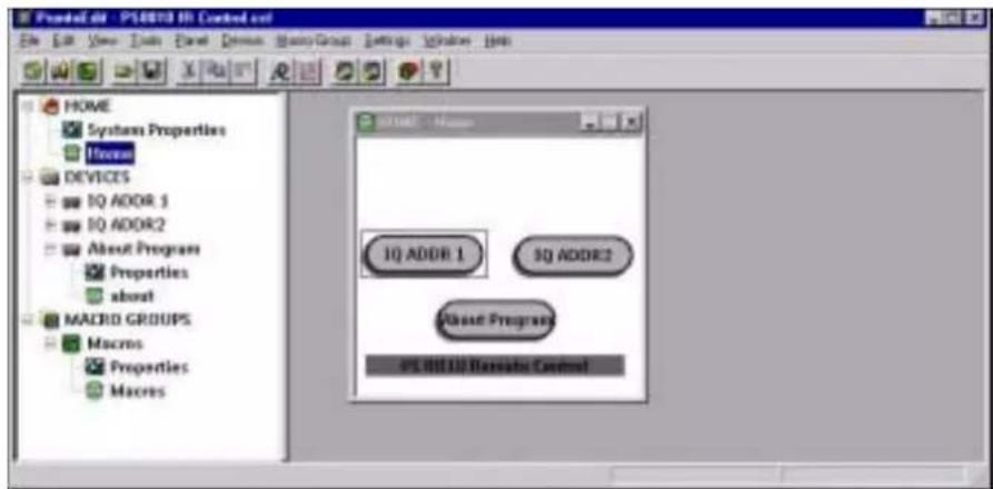
The screen will look like the screen shot below.
The "HOME" folder contains the buttons located on the home page. Double clicking on "Home" under the "HOME" folder will open the 'Home' panel in the window to the right.
IQ ADDR 1 is a jump to the IQ ADDR 1 page. This is actually a
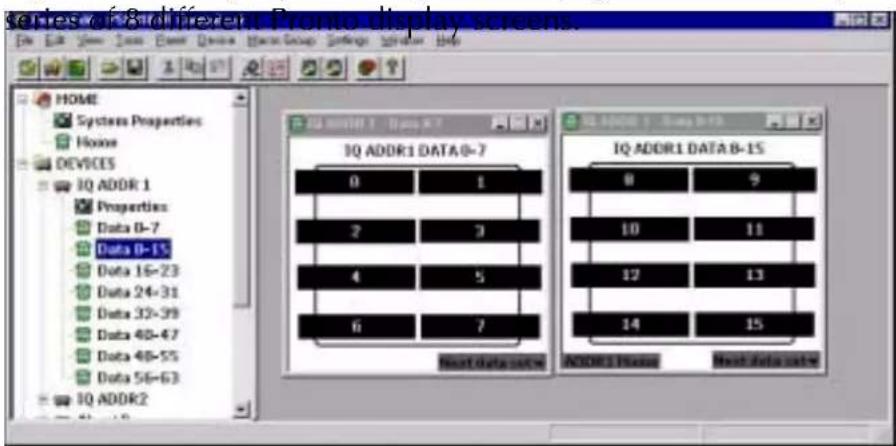
Infrared Remote Control Philips Pronto
Each page contains 8 buttons. There are a total of 64 buttons (0-These buttons correspond to the 64 different code # buttons on the IQ Win control page. These buttons will only work if the IQ address of the PS-8810 is set to 1.
Similarly, there are 64 buttons under the device IQ ADDR 2. These buttons will only work if the IQ address of the PS-8810 is set to 2.
To change the IQ address of the PS-8810 Pronto controls, open the properties window up for each button. This is done by right clicking on the button and selecting properties. The following window will appear.
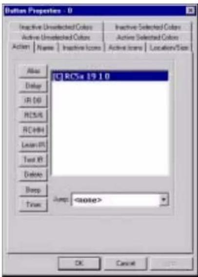
Under the 'Action' tab the RC5x command is displayed. In this case it is "19 1 0", this command will select a PS-8810 device at IQ Address 1 and send code#0. With this code highlighted, press the delete button. Now a new code can be entered.
It is also possible to enter more than one command. In this case, pressing the button on the remote will transmit multiple commands for perhaps controlling multiple mixers or other IR controllable equipment.
To enter a new code, click on the 'RC5/6' button. This allows you to define a new RC5 or RC6 command. For the PS-8810, an RC5x command is required.
Infrared Remote Control Philips Pronto
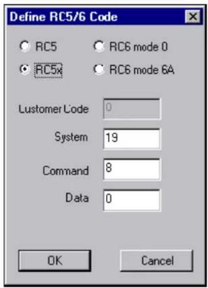
- Select the button for RC5x.
- Enter in 19 for System (19 defines a PS-8810).
- Enter the IQ address (0-63) for Command.
- Enter the code # (0-63) for Data.
Once all of the buttons and windows are set up, save the program as a *.ccf file type.
Download the program into the pronto and try it out.
PS8810 IR Code Format
The PS8810 uses the Philips RC5x IR command format. The following diagram shows the IR command string.
Every RC5x command must begin with 2 start bits and a toggle bit. The toggle bit is 0, unless the command is repeated, in which case, it simply toggles for each instance of the repeated command. These three bits are followed by the Device Type (A4-A0), the command bits (C7-C0) and the data bits (D5-D0), which are described below.

| Address (19) | Command (IQ Address) | Data (IR Command #) |
| The 5 address bits define what device the data is for (i.e. TV, VCR,...mixer). The PS8810 is defined by #19 decimal (10011)binary | The 8 command bits define the IQ Address of the mixer. Due to the format of RC5x, The C7 and C6 bits are ALWAYS=0. Valid IQ Addresses are 1- 63. | The 6 data bits define the IQ command. 6-bits allows for 64 commands. These commands are user defined in the mixer using IQ for Window's Software. |
Some Remote controls such as the Philips Pronto allow users to manually enter the IR code to be transmitted. In this case, you would enter the commands as shown below.
IQ Address=1, Select user defined command number 0 (19 1 0)

IQ Address=1, Select user defined command number 1 (19 1 1)

IQ Address=1, Select user defined command number 2 (19 1 2)

IQ Address=1, Select user defined command number 3 (19 1 3)


IQ Address=1, Select user defined command number 63 (19 1 63)

IQ Address=20, Select user defined command number 25 (19 20 25)

17.0 Control Port
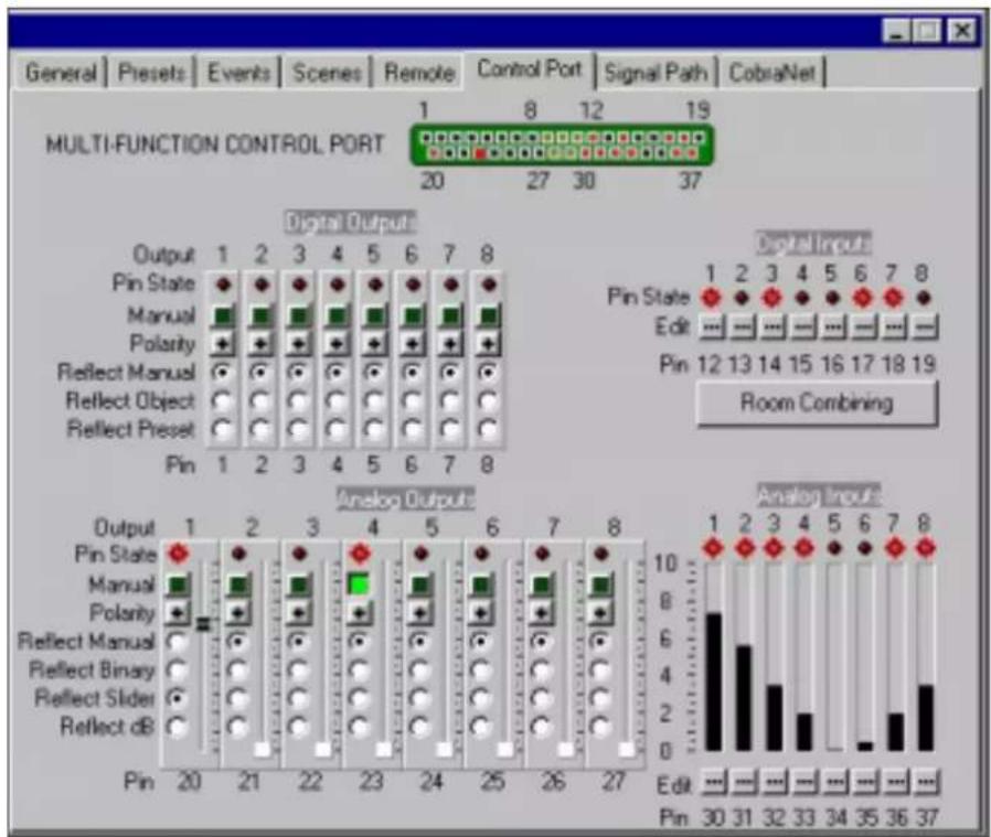
The Control Port provides a means for external monitoring and control of 'objects' within the BSS PS-8810. It can be used to turn peripherals on and off, send signals to other system components, receive digital and/or analogue signals from other components, and indicate status of the input gates.
The Control Port implements sixteen outputs and sixteen inputs along with power supply outputs and common grounds.
Eight of the outputs are digital 'logic outs', while the other eight are analogue outputs that are capable of digital 'logic outs'.
Eight of the inputs (AIN1-8) are capable of monitoring digital and analogue external signals.
The other eight inputs (DIN1-8) are digital only.
Control Port Digital Inputs (DIN 1-8)
Digital Inputs
These inputs are digital (high or low) only. The inputs are current driven and will accept voltages up to +25VDC. They switch at approximately +1VDC. They can be used to control one or more objects within the BSS PS-8810. The Pin State Indicator shows the actual status of the hardware input as it comes into the rear panel connector.
When the Edit button is pressed on a Digital Input, the Control Port Assignment Dialogue box appears to assist in setup of the input.
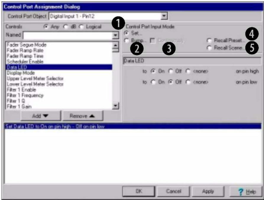
The Controls buttons allow filtering of the objects to allow only certain objects to be displayed. The Named window allows input of text to narrow the search. Once the desired object has been found, highlighting and pressing of the Add button adds it to the object list on the bottom of the window. By highlighting a particular object in the bottom window, the attributes of the object can be edited. Binary objects can be chosen on a particular digital input level, while multiple choice objects can be given specific choices.
① Set Object(s)
Allows a single input to control up to fifty objects within the BSS PS-8810. Binary objects can be controlled with normal or
Control Port Digital Inputs (DIN 1-8)
inverted logic. Multi-valued objects (e.g. gains, thresholds, etc.) can be set to different settings for input transitions from low-to-high and high-to-low.
② Bump Object(s)
Similar to Set Object mode except that rather than setting the object to an absolute value, the specified values are added to the current object values. Upper and lower limits can be set to limit the range of the control.
③ Bump Object(s) Continuously
Similar to Bump Object mode, except that the specified values are added to the object value continuously at 14 second intervals.
④ Recall Preset
Enables the input to recall one of the 32 user Presets. Separate Presets can be recalled for low-to-high and high-to-low transitions.
⑤ Recall Scene
Enables the input to recall one of the 32 user Scenes. Separate Scenes can be recalled for low-to-high and high-to-low transitions.
Room Combine
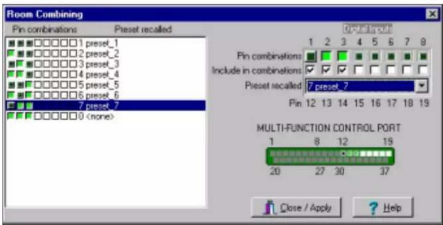
Enables the digital inputs to be used in a binary combination of digital inputs to recall one of the 32 user Presets. Using all inputs (1-8) allows up to 256 unique combinations. Lesser numbers of inputs can be used for fewer combinations. This mode can be used for room-combining applications where switch-closures indicate moving room dividers. By selecting which digital inputs
Control Port Digital Inputs (DIN 1-8)
are to participate in the room combining, individual closure patterns can be programmed to trigger particular Presets. Each combination can be programmed to its own Preset. The example screen shot shows three digital inputs participating in an 8 option room combining scheme. All three inputs off selects Preset 1, while input 1 on while inputs 2&3 are off select 2, and so forth. This allows a highly flexible programming scheme for any room combining design.
Uses:
The Control Port digital inputs can be used to sense logic 'high' or 'low' signals to control many of the features of the BSS PS-8810. The inputs are current driven and will accept +5V or +10V inputs, and are well suited for sensing contact closure.
One particularly useful way to use the Logic Input Control Mode is to sense the opening and closing of switches in a room-combining system. Switches are mounted in retractable partitions between rooms. When a partition is opened, the signal at the digital input will be interpreted as a logic 'low', and when the partition is closed, the signal at the digital input will be interpreted as a logic 'high'. When specific mapped combinations of logic lows and highs are sensed, the BSS PS-8810 will activate a Preset to tailor the audio system to the currently configured space.
Another possible use for the Logic Input Control Mode is to sense switch closures along the path of a ride in a theme park, to signal the ride's location, and change to different Presets accordingly.
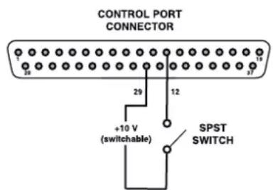
Sample Control Port Analogue Input Circuit
Control Port Digital Outputs
Digital Outputs
There are eight digital outputs. Each output may be controlled manually, configured to indicate the state of a binary object or, configured to indicate whether a particular Preset is loaded. There is one indicator and five controls for each output:
- Pin State Indicator: indicates the logical 'Pin-High' or 'Pin-Low' status of the actual hardware output
- Manual: directly controls the output state of the corresponding pin when in Manual mode
- Polarity: changes the polarity of the digital output regardless of the pin control mode
- Reflect Manual: causes the output to directly reflect the state of its Manual control
- Reflect Object: causes the output to reflect the state of the selected binary object within the BSS PS-8810. Only a single object may be specified.
- Reflect Preset: causes the output to reflect whether the chosen Preset number is loaded within the BSS PS-8810
When the Control Port digital outputs are turned 'on', +10VDC at 10 mA is supplied across the output to ground. A total of 1 amp of current is available.
Control Port Digital Outputs
There are many possible uses for the Control Port outputs. For example, they can be used to turn on auxiliary cooling fans. To do this the output signal might be used to close a relay. The relay would then turn the fans on or off.
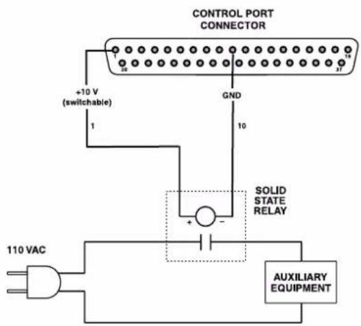
A Sample Control Port Output Circuit
By monitoring the operating condition of amplifiers (with the IQ System software), the need for additional cooling would be apparent. The software could then be used to turn on the appropriate Control Port input.
Another use for the Control Port outputs might be to light an LED on an annunciator panel to indicate Preset status, input channel mute, or any other on/off type function.
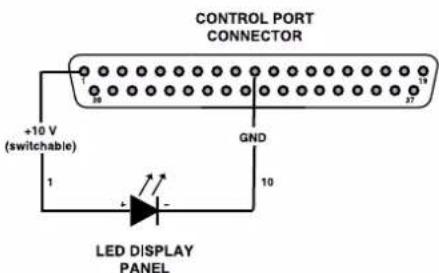
A Sample Control Port Output LED Circuit
Control Port Analogue Inputs
Analogue Inputs (AIN 1-8)
The Control Port analogue inputs allow a 0 to +10VDC signal to be input to allow remote control of continuously variable objects such as faders or filter frequencies. They can also be used to control switched objects (just like the Digital Inputs). When the Edit button associated with a particular input is pressed, the Control Port Assignment Dialogue box appears and allows programming of the input just as was discussed for the Digital Inputs.
These inputs can be used to sense the presence of an analogue input signal level, such as ordinary 10kOhm linear potentiometers for level control. Analogue inputs can alternately be set to sense simple contact closure.
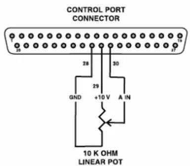
Sample Control Port Digital Input Circuit
A screw-terminal board with barrier-block to DB37M connections makes it easy to interface external circuitry to the Control Port.
ComputerBoards, Inc. offers a suitable screw-terminal board (part number CIO-MINI37), along with an enclosure (part number ENC-MINI37) for this use.
Contact ComputerBoards, Inc. at www.computerboards.com or (508)946-5100.
Control Port Analogue Outputs
Analogue Outputs
In addition to the eight Digital Outputs, there are eight Analogue Outputs that can be used to provide an output voltage (0 to +10VDC for control). These outputs can reflect a particular analogue object such as a fader, or a switched object and, can be used to provide drive for such things as lighting controls or for a standard digital type output.
The settings are remembered in a Preset, so they can be used to change the voltage of a particular output based upon Preset.
There is one indicator and six controls for each output.
- Pin State Indicator: indicates the logical 'Pin-High' or 'Pin-Low' status of the actual hardware output
- Manual: directly controls the binary output state of the corresponding pin when in Manual mode
- Polarity: changes the polarity of the analogue output regardless of the pin control mode
- Reflect Manual: causes the output to directly reflect the state of its Manual control
- Reflect Binary: causes the digital output to reflect the state of the selected binary object within the BSS PS-8810. Only a single object may be specified
- Reflect Slider: causes the analogue output to reflect the setting of the slider control associated with the output
- Reflect db: causes the analogue output to reflect the status of the selected db object. Only a single db object may be specified.
Reference Section
18.0 Technical Information
Technical Description
Following is a technical description of the operation of the BSS PS-8810.
Audio Input Section
Each audio input signal first passes through a balanced filter designed to eliminate RF interference. The RF filters are a balanced network of chokes, ferrite beads, and capacitors that attenuate both common-mode and differential-mode signals above 500 kHz. Optional input isolation transformers are available.
The balanced signal then enters the input switching circuit. This circuit can insert a 25dB pad for line level signals or apply phantom power to the input terminals (24VDC through two 2 Kohm resistors). The signal is filtered again to eliminate lower-frequency RF energy such as interference from the AM broadcast band.
A discrete preamp stage takes the balanced input signal and provides 13 to 45 dB of voltage gain adjustable by a rear panel potentiometer. The preamp output provides a single-ended voltage output that is then coupled to a single-ended-to-differential amplifier that also provides the bias offset needed by the A/D converter.
A 24-bit high-resolution A/D converter samples the input audio at 48 kHz. The audio processing is set to provide +20dBu as full scale, allowing full utilization of the dynamic range of the converter. Each converter supplies a two-channel digital audio stream to the DSPs for processing. One A/D converter acts as a master to supply sampling clocks to the rest of the system. A 12.288 MHz oscillator (256 times the 48 kHz sampling rate) acts as the master clock source.
DSP Processing Section
Four DSP processors supply all of the digital audio processing in the unit. Serial digital audio from the input converters is sent to the DSP board for processing. Digital audio from either the Input board or the CobraNet board is routed to the two input DSPs. The processors collect 16 samples of audio, then process the
Technical Information
audio as a 'brick' of data. After the input DSPs have processed the data, they transfer the audio bricks to shared memory. The two output DSPs then retrieve the audio from memory and do the required output processing. The audio is then sent serially from the DSPs serial ports either to the Output board or the CobraNet outputs.
The DSP processors have a 30 MHz clock, while serial digital audio is locked to serial clock (3 MHz) and frame sync clock (48 KHz) supplied from the Input board.
An interface to the System Controller board allows programming of the DSPs, control updates, and metering information to be passed to the outside world. The DSPs depend upon the System Controller for programming upon reset or initial power, as there is no nonvolatile memory on board.
Output Section
Output serial digital audio from the DSP board is sent to the output board for conversion and analogue processing. The serial digital audio is comprised of two channels of 24-bit signals. Each DAC converts the audio data stream into two differential output channels. A differential amplifier filters the DAC's audio output and provides single-ended audio to a gain stage that sets the full-scale output of the DAC. A single-ended-to-differential stage provides a 50-ohm output. Optional transformers are available for the Main Outputs.
Control and Interface
System Controller
The System Controller board provides interface to the outside world as well as providing all of the program storage and initialization.
At reset, the control processor uses boot code from nonvolatile flash memory. Program code is then transferred to fast RAM and the processor begins to run. Each DSP processor is then booted via the system interface and upon successful booting of all the DSPs, audio processing begins.
Technical Information
- Flash Memory Storage:
In addition to storing program code for the control and DSP processors, flash memory provides storage for all nonvolatile data including Presets and setting
- IQ Loop:
The dual RJ-45 connector allows IN/OUT connection to an IQ loop. The BSS PS-8810 can act as either an ordinary component or an interface. When acting as an interface, a computer needs to be connected to the RS232 interface
• RS232:
When the BSS PS-8810 is in interface mode, the computer communicates with the BSS PS-8810 and all components on its IQ loop via this port. Front Panel control allows setting of the baud rate, and IQ for Windows software automatically adjusts to this setting. When in the component mode, the BSS PS-8810 can still communicate with the computer through this port
- DSP Interface:
The control processor boots all of the DSP processors via this interface. Additionally, the control processor sets all audio processing controls and receives all meter data over this port.
• Real Time Clock: An internal real time clock allows Presets to be called based upon a real time. The event scheduler works independently of the computer and can recall a specific Preset either as a one-time function or a repeatable event with a specific start time and repeat rate. The clock is capable of retaining the correct time for up to 45 days without power applied the BSS PS-8810
- Front Display: The control processor communicates to the front display via a serial interface. All LED updates and display information is passed to the front panel in this manner. The control processor monitors the front-panel switches
- Power Interface: The System Controller board receives voltages from the power supply and routes them to the Input and DSP boards. A regulator creates the +10V available for the Control Port
Technical Information
- Control Port:
External events can be either generated or monitored via this port and used to control or signal some function within the unit. Sixteen digital outputs, eight digital inputs, and eight analogue inputs provide access to the unit. current-limited voltages (+5V and +10V) are provided to power external circuits
Digital Outputs:
These eight outputs provide +10V at 10mA as configured by IQ software. These outputs can signal either a specific event or can signal the gate status of the input channels
Analogue Outputs:
These eight 0 to +10VDC inputs can be mapped to any object in the box for control. Fader objects can be mapped to allow remote control of a particular fader
Digital Inputs:
Eight switched inputs can be linked to specific functions, such as muters, in the unit. These inputs can also be used to select a particular Preset based upon a desired switch combination on these inputs. The inputs are current driven and will accept any DC voltage to +25VDC
Analogue Inputs:
Any fader in the unit can be controlled via one of these inputs. A 10VDC swing allows the control to vary from null to full scale. IQ software controls provide limiting of the fader value in the unit
19.0 Block Diagram
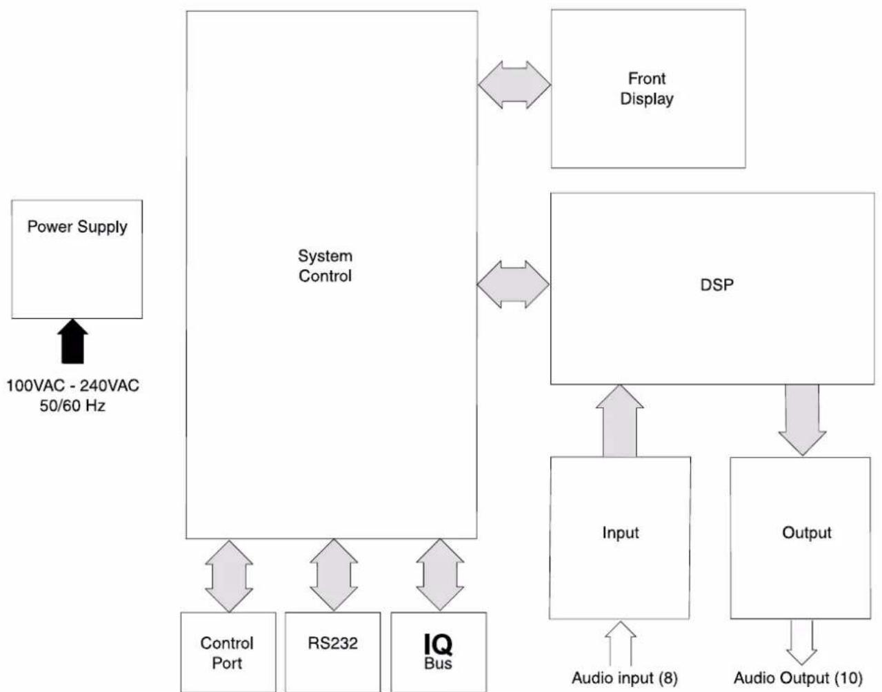
flowchart
graph TD
    A["Power Supply"] -->|100VAC - 240VAC 50/60 Hz| B["System Control"]
    B --> C["Front Display"]
    B --> D["DSP"]
    D --> E["Input"]
    D --> F["Output"]
    E --> G["Control Port"]
    E --> H["RS232"]
    E --> I["IQ Bus"]
    F --> J["Audio input (8)"]
    F --> K["Audio Output (10)"]
20.0 Specifications
Front Panel Controls: Front-panel switches select IQ Address, Baud Rate, any of 32 user programmable Scenes, and any of 32 user-defined Presets (P01-P32)
Rear-Panel Controls: A 3-position selector switch (mic/line/phantom) and a calibrated gain control for each input
Connectors:
IQ Loop: RJ-45 for input/output
RS232: RJ-45 for 'daisy chain' output
Control Port: DB9F computer interface for both component and interface modes DB37M for analogue inputs, digital inputs, digital outputs, +5VDC, +10VDC and Ground. Audio Inputs and Outputs
Audio: 3-pin male removable barrier block connectors, Buchanan® type cable connector or equivalent supplied
AC Power: IEC320 connector for AC power cord
Display: Front-panel 'Power' indicator lights to show that the unit is plugged in and AC power is being supplied
An amber front-panel 'Data' Signal Presence Indicator (DATA) flashes whenever commands addressed to the BSS PS-8810 are received
A green front-panel 'IQ Interface' indicator lights when the BSS PS-8810 is being used as system interface
A three character segmented digital display indicates the BSS PS8810's initialization sequence by displaying each processor's name as it comes on-line. Also indicates the presently selected Preset, IQ address and baud rate while those parameters are being adjusted and indicates when a parameter has been stored in flash memory or when any parameter is varied from its value within the currently selected Preset
A front panel, sixteen-segment LED display matrix can be set to three different operating modes: 'Level Meter', 'Gate Status', and 'Infinity Pattern'
Specifications
Power Requirements: 100VAC to 240VAC, 24W nominal
Protection: If communication is lost, the unit will continue to function with the last commands received
RS232 Data Communication:
Baud Rate: Selectable to 19.2K, 38.4K, 57.6K, or 115.2K BAUD
Data Format: Serial, binary, asynchronous; 1 start bit; 1 stop bit; 8 data bits; no parity
Data Rate: 38.4 K BAUD
Data Format: Serial, binary, asynchronous; 1 start bit; 1 stop bit; 8 data bits; no parity
IQ Loop Data Communication:
IQ Loop Interface Type: Optically isolated 20mA current loop
Operation: Half-duplex
Transmission Distance: Variable from 200 to 3000 feet (61 to 914 meters), depending upon wire capacitance. Typically 1000 feet (305 meters) using shielded twisted-pair wire, #26 AWG or larger. Can be extended with an IQ Repeater
Audio:
Phantom power voltage: +24VDC at 10mA
Input Gain Range: +20 dBu to -12dBu (additional 25 dB for mic setting)
Digital Sampling: 24 bit, 48kHz
Input Impedance: 20kOhms balanced, 10kohms unbalanced
Dynamic Range: Greater than 100dB (A-weighted, 20 Hz-20KHz)
Frequency Response: 20Hz-20kHz, ± 0.5dB
Common Mode
Rejection: 50dB (typical)
Crosstalk: Greater than 80dB at 10kHz
Total Harmonic
Distortion: Less than 0.05% THD + N (1kHz, 0dBu)
Output Impedance: 100 Ohms balanced, 50 Ohms unbalanced
Max Input Level: +32dBu (line) or +7dBu (mic)
Max Output Level: +20dBu
Specifications
Control Port:
Power Supply: +5VDC and +10VDC outputs are provided. The total output current is limited to 1A
Outputs:
Logic Low: less than 0.1V
Logic High: 10V (via internal pull-up) Output Current is limited to 10mA max per pin
Inputs:
Input Impedance: greater than 50kOhm
Logic Low: less than 0.5V
Logic High: greater than 5V
Analogue Range: 0 to 10V (for inputs 9-16 only)
Max Input Voltage: 25V
Mechanical:
Weight: 13 pounds, 4 ounces (6.1 kg)
Dimensions: Width: 19-inch (483-cm) standard rack mount (EIA RS-310-B)
Depth: 16-inch (40.6-cm) behind mounting surface
Height: 3.5-inches (8.9-cm)
21.0 User Notes
User Notes
- Prosys™
- PS-8810
- Digital Signal Processor
- IMPORTANT SAFETY INFORMATION
- THIS EQUIPMENT MUST BE EARTHED.
- REGULATORY INFORMATION
- Important Safety Instructions
- Contents
- Important Safety Instructions.... 2
- Controls, Connectors & Indicators
- Front Panel 16
- Rear panel ....19
- Using the PS-8810
- Quick Install Procedure 23
- Hardware Installation & Connections .....25
- Programming the PS-8810 with IQ for Windows
- IQ Win Overview ....44
- Processing Functions ....48
- DSP 50
- General 51
- Signal Path 53
- Input Path 54
- Input Filters 56
- Input Delay 59
- Hardware Delays 59
- Input Gate 60
- Auto-Leveler 62
- Input Compressor....64
- Automixer 66
- CobraNet® 89
- External Control
- Infrared Remote Control 97
- Control Port 103
- Reference Section
- Technical Information 112
- Block Diagram.... 116
- Specifications 117
- User Notes 120
- Primary Checks
- Installation
- Warranty Information
- IMPORTANT
- Unit Serial Number:
- Warranty Information
- Worldwide Warranty terms:
- United States (US) Warranty Coverage:
- Introduction
- Introduction
- PS-8810C
- BSS PS-8810
- BSS PS-8810C
- Front Panel
- a: Power Indicator
- b: DATA Indicator
- c: IQ Interface Indicator
- d: Input Gate Status Display
- e: Digital Display
- Front Panel
- f: Selector Buttons
- g: RECALL Button
- h: IR Sensor
- i: RS232 connector
- Rear panel
- A: Audio Inputs
- Input Selector
- Audio Input Gain Control
- B: Audio Outputs
- Main and AUX Audio Outputs
- Rear panel
- C: CobraNet® Connectors
- CobraNet Connections and Indicators
- D: IQ Loop Connectors
- IQ Loop Input/Output Connector
- IQ Loop Output Connector
- E: RS232 Serial Port
- RS232 Serial Port
- F: Control Port
- G: Mains Power Inlet
- AC Line Connector
- Quick Install Procedure
- Installation:
- Configure the BSS PS-8810:
- Connections:
- Quick Install Procedure
- Prepare the BSS PS-8810:
- Prepare the audio system:
- Hardware Installation & Connections
- Connections Computer
- Connecting to a Host Computer
- RS232 Computer Connection
- ConnectionsComputer
- RS232 Cable Wiring
- Set the Baud Rate
- Comms Problems
- Connections IQ Loop
- Connecting the IQ Loop
- Set the IQ Address
- To set the address:
- PS-8810 as a single loop IQ Interface
- PS-8810 in an IQ Loop system
- IQ Component Connections
- RJ-45 Plug
- IQ Loop Wiring
- Connections Audio
- Audio Wiring
- About the Audio Inputs
- Suggested Audio Input Gain Control Settings
- Balanced Input Wiring
- Unbalanced Input Wiring
- About the Audio Outputs
- Balanced Output Wiring
- CobraNet® Connections
- Connections CobraNet
- Connections Control Port
- Control Port Connections
- PIN PIN PIN PIN
- Control Port Pin Assignment
- Connections Modem Connection
- Modem Connection
- IQ Win Overview
- PC Requirements
- System Overview
- Presets and Scenes
- IQ Win Notes
- IQ Win Overview
- Quick Set Up
- Processing Functions Metering & Status
- Metering
- ① Output Level Meters
- ② Output Dynamic Cut/Boost Meters
- ③ Input Level Meters
- Processing Functions Metering & Status
- ④ Input Dynamic Cut/Boost Meters
- ⑤ Preset Information
- ⑥ Status Window
- ⑦ CPU Utilisation
- Processing Functions DSP
- Processing Functions General
- General
- ① Real Time Clock
- ② Front Panel Control Lock Out
- ③ Data
- ④ Interface
- ⑤ LED Display Mode
- ⑥ Front Panel Access
- ⑦ User Labels
- ⑧ Firmware Information
- Processing Functions Signal Path
- Signal Path
- Processing Functions Input Path
- Input Path
- Input Meter
- Input Select Switch
- Input Processing Selection
- ⑤ Input Signal Fader, Muter, and Inverter
- Output Overview
- ⑦ Inputs Window Link
- ⑧ Input/Output Matrix Link
- Processing Functions Input Filters
- Type
- Frequency
- Gain
- Band EQ
- Shape
- Post-Processing Filters
- Processing Functions Input Delay
- Input Delay
- Hardware Delays
- Processing Functions Input Gate
- Input Gate
- ① Enable Gate
- ② Depth
- ③ Static Threshold
- ④ Hysteresis
- ⑤ Signal Delay
- ⑥ Attack Time
- ⑦ Hold Time
- ⑧ Release Time
- ⑨ Side-chain Filter
- Processing Functions Auto-leveler
- Auto-Leveler
- ① On/Off
- ② Target Level
- ③ Max Gain
- ④ Idle Gain
- ⑤ Open to...
- ⑥ Threshold
- ⑦ Attack Time
- Processing Functions Input Compressor
- Input Compressor
- ② Compression Ratio
- ③ Threshold
- ④ Soft Knee (Width)
- ⑤ Attack Time
- ⑥ Release Time
- ⑦ Side-chain Filter
- Processing Functions Auto-Mixer
- Automixer
- Priority Ducking
- Input gates must be enabled for all inputs participating in Priority Ducking within an Automix Group.
- NOM Attenuation
- ⑤ Enable
- ⑥ Mode
- ⑦ Step Size
- Adaptive Gating
- ⑧ Enable
- Ambient Level Meter
- Group Gate Threshold Ambient Offset
- Individual Control:
- Ambience Weighting
- Automix Matrix
- ① Priority
- ② Depth of Cut
- ③ Attack Time
- ④ Release Time
- Processing Functions Solo/Mute
- Solo/Mute Solo/Mute
- Processing Functions Input/Output Matrix
- Input/Output Matrix
- Processing Functions Output Path
- Output Path
- Processing Functions Output Section
- Output Section Output Processing Sections
- Output Delay
- Output Filters
- Processing Functions Ambient Leveler
- ④ Expansion Ratio
- ⑤ Max Added Gain
- ⑦ Release Time
- Program Level Dependent Mode
- ⑧ Program Level Threshold
- ⑨ Sense Delay
- Processing Functions Output Limiter
- Processing Functions Output Select
- Output Select
- Presets
- Scenes
- Try Edit Name # Try Edit Name
- Scenes
- Scene Editor
- Events Scheduler
- Events Scheduler
- One Time Events
- Periodic Events
- Schedule
- CobraNet®
- CobraNet ®
- Explanation
- Setup
- IP Address
- ⑧ Conductor
- ⑨ Status indicators
- Input
- Output
- Infrared Remote Control
- Infrared Remote Control IR Code Editor
- IR Code Editor
- Infrared Remote Control Philips Pronto
- Philips Pronto
- PS8810 IR Code Format
- Control Port
- Control Port Digital Inputs (DIN 1-8)
- Digital Inputs
- ① Set Object(s)
- ② Bump Object(s)
- ③ Bump Object(s) Continuously
- ④ Recall Preset
- ⑤ Recall Scene
- Room Combine
- Uses:
- Control Port Digital Outputs
- Digital Outputs
- Control Port Analogue Inputs
- Analogue Inputs (AIN 1-8)
- Control Port Analogue Outputs
- Analogue Outputs
- Technical Information
- Technical Description
- Audio Input Section
- DSP Processing Section
- Technical Information
- Output Section
- Control and Interface
- System Controller
- - Flash Memory Storage:
- - IQ Loop:
- • RS232:
- - DSP Interface:
- - Control Port:
- Digital Outputs:
- Analogue Outputs:
- Digital Inputs:
- Analogue Inputs:
- Specifications
- Specifications
- User Notes
- User Notes
Brand : BSS Audio
Model : PS-8810
Category : Uncategorized