
UV1-S - Audio/video extender Hall Research - Free user manual and instructions
Find the device manual for free UV1-S Hall Research in PDF.


| Brand | Hall Research |
| Model | UV1-S |
| Product Type | Audio/Video Extender (Sender) |
| Video Formats | RGB, YPbPr (component) |
| Maximum Resolution | Up to 1920 x 1440 non-interlaced at 60 Hz |
| Bandwidth | DC to 250 MHz |
| Maximum Distance | 500 ft (152 m) for VGA/Component |
| Connectors | 1 x HD15 female (VGA input), 1 x RJ45 (CAT5 output) |
| Power over UTP | Yes |
| Number of RJ45 Outputs | 1 |
| Local Loop Out | No |
| Wall Mountable | No (model UV1-S is not wall-mountable) |
| Power Supply | External universal supply; output 9 V DC, center-positive |
| Compliance | CE, FCC Part 15 Subpart B Class A |
| Dimensions (H x W x L) | 0.8" x 1.7" x 4.5" (20.3 x 43.2 x 114.3 mm) |
| Features | Transmits video and power over one CAT5 cable; adjustable cable length compensation; only one power supply needed for sender and all receivers; rugged, compact size |
Frequently Asked Questions - UV1-S Hall Research
User questions about UV1-S Hall Research
0 question about this device. Answer the ones you know or ask your own.
Ask a new question about this device
Download the instructions for your Audio/video extender in PDF format for free! Find your manual UV1-S - Hall Research and take your electronic device back in hand. On this page are published all the documents necessary for the use of your device. UV1-S by Hall Research.
USER MANUAL UV1-S Hall Research
Order toll-free in the U.S. 800-959-6439
FREE technical support, Call 714-641-6607 or fax 714-641-6698
Mail order: Hall Research, 1163 Warner Ave. Tustin, CA 92780
Web site: www.hallresearch.com E-mail: info@hallresearch.com
VGA + Power Over UTP
Table of Contents
1.0 GENERAL DESCRIPTION 2
1.1 NOTE FOR -CV MODELS 3
2.0 FEATURES....4
3.0 SETUP AND OPERATION 4
3.1 IMPORTANT NOTE REGARDING SELECTING THE UTP CABLE....7
3.2 DIP SWITCH SETTINGS FOR THE MODEL UV1-SL 8
4.0 SPECIFICATIONS....9
VGA + Power Over UTP

flowchart
graph TD
    A["Video Source"] -->|VGA| B["Model UV2-S"]
    C["Local Monitor"] -->|VGA| B
    B -->|Only 1 Power Supply need for entire setup| D["Remote Monitors"]
    B -->|Cat-5 Cable| E["UV1-R"]
    B -->|Cat-5 Cable| F["UV1-R"]
1.0 General Description
This User's Manual covers the Mini-Cat® series of high-resolution PC or HDTV component video transmission system.
The transmission systems are comprised of one Sender unit and one or more Receiver units. They enable you to split and extend a PC VGA video or analog Component HDTV signal up to 500 feet.
A unique feature of the system is that in most installations only one power supply is enough to power the sender and the receiver(s). All sender units can supply power to all the receivers connected to them via the Cat5 cable. If the cable is longer than 330 feet or 100 m then the receiver may require a separate supply. Conversely, in the case of 1-to-1 setups, the Receiver unit can also supply power to the Sender (only when the Sender is a single channel).
VGA + Power Over UTP
The characteristics of the Sender units are summarized below:
| Feature | Local Loop Out | RJ45 Outputs | Power Over UTP | Wall Mount |
| UV1-S | No | 1 | Yes | No |
| UV1-S-DP | No | 1 | Yes | Yes |
| UV1-S-WP | No | 1 | Yes | Yes |
| UV1-SL | Yes | 1 | Yes | No |
| UV1-SL-DP | Yes | 1 | Yes | Yes |
| UV2-S | Yes | 2 | Yes | No |
| UV4-S | Yes | 4 | Yes | No |
| UV8-S | Yes | 8 | Yes | No |
Table 1 - Sender Characteristics
Note: For Cat-5 runs of over 330 feet, the receivers may need their own additional supplies sold separately (HRT model # 511-GS569).
1.1 Note for -CV models:
The Mini-Cat ^® series senders can be built to extend Composite Video and Stereo Audio up to 2000 feet, and are sold with HD15 to 3 RCA A/V cables. These models are labeled with -CV (e.g.: UV2-S-CV) and are not compatible with VGA signals. The Model UV1-SL is also capable of extending Composite Video & Stereo Audio by setting a dip switch (see section 3.2).
2.0 Features
• Transmit video and power on one cable
- Senders with multiple outputs for splitting to multiple displays
• Handles resolutions up to 1920x1440
• Drives standard CAT5 cables to 500 feet
• Adjustable cable length compensation at each receiver
• Only one power supply required for sender and all receivers
• Rugged, Reliable, Compact size
3.0 Setup and Operation
A. Place the sender near the video source and connect it to your source using the cable provided.
- For PC's VGA output use a HD15 male-to-male cable (generally a short cable may be included with your package)
- For RGB or YPbPr sources, use a HD15 to 3 RCA cable (Hall Research Model # CHD15-3RCA-length 03 = 3ft, 06 = 6 ft).
●
B. Use an Unshielded Twisted Pair (UTP) or a Shielded Twisted pair (STP) cable such as Cat5, 5e, or 6 wired per standard 568B to connect the sender to the receiver(s). See Section 3.1 for important cable selection considerations.
VGA + Power Over UTP
IMPORTANT
Do not connect this unit to any LAN device such as network cards or hubs as this may cause damage. Use EIA/TIA 568B standard straight-through patch wiring as shown below. Do not use crossover cables.
| EIA/TIA 568B WIRING STANDARD | |
| PIN | Wire Color |
| 1 | White w/ Orange Stripe |
| 2 | Orange |
| 3 | White w/Green Stripe |
| 4 | Blue |
| 5 | White w/Blue Stripe |
| 6 | Green |
| 7 | White w/Brown Stripe |
| 8 | Brown |

Figure 2
C. At each remote site connect a receiver to the Cat5 cable and plug your display to its HD15 output connector.
D. Plug a power supply to the System based on the type of the sender used. In general, you should connect the power supply to the Sender unit. However, follow these suggestions for best performance.
- If the sender has more than one RJ45 output then the power supply must be connected to the sender.
- If the system is comprised of only one sender and one receiver, then you can supply power at either the sender or the receiver.
VGA + Power Over UTP
Wallplate Power Connection
The wall plate units have a 2 pin screw terminal for power connection on the back of the unit. You need to connect 6 vDC (could be 6 to 9vDC) to these terminals.
In your package there is either of the 2 power supplies pictured. There is also a 2.5 ~mm Jack included in the package so that you don't have to cut the connector at the end of the power supply. If you decide not to cut off the power supply connector, then solder a pair of wires to the enclosed jack and connect those to the power terminals.

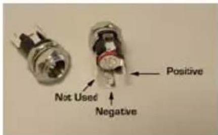
Using the supplied 2.5mm Jack also gives you the ability to place the power supply outside the wall. You can use a separate single gang plate and install the supplied jack on it and wire it to the terminals on the back of the wall units.
You can use 20 awg or heavier wire to extend the DC output cord of the power supply if you need to locate the power supply farther from the device. It is recommended to keep the distance of the supply from the unit to within 30 feet.
Note: Please do not connect the power supply to the AC source until you have securely connected the output cords to the Wall Plate Mini-Cat unit.
Electrical Safety Note
Since the DC supply to the unit is only 6 to 9 vDC with minimal current requirements, the product qualifies as a Class 2 low-voltage device, and you are not required to run the DC cables in a conduit. However if you will be installing the power supply in the wall or ceiling, since it has to plug in to AC, you need an electrical junction box for it, and the AC line that brings high-voltage to the junction-box should follow the electrical code for your specific installation
VGA + Power Over UTP
E. Apply a video source to the system and check for an image at each receiver, then set the compensation Potentiometer (pot) for best possible image. Start with the compensation pot fully CCW (least compensation), then slowly turn it clockwise and check for the bleeding of left to right horizontal lines on the screen. See Figure 3.

Figure 3
3.1 Important note regarding selecting the UTP Cable
First of all, UTP (unshielded) is preferred over STP (shielded) unless you are running the cable very close to AC power lines, power transformers, or ballasts of fluorescent lights, where EMI (electro-magnetic interference) can get into the video if it is strong enough.
Secondly, for best results especially for distances of over 150 feet, it is highly recommended to use a Zero-Skew Cat5 cable. (Part # CUTP-Z-1000).
VGA + Power Over UTP
This cable ensures that the horizontal alignment of the red, green, and blue components of the video signal is maintained regardless of the length of the Cat5 cable. In this cable, the number of twists in each of the 4 pairs in the cable is the same. If you do not use a Zero Skew cable and feel that the RGB alignment is off by an unacceptable level, then you can use a Skew Corrector (Hall Research Model SKU-RGB) at the display device if desired.
- For Cat5 runs of over 330 ft, you may need to connect a power supply to the sender as well as the receiver. This is due to the fact that the resistance of the cable causes a voltage drop from the sender to the receiver and the voltage level of the power at the receiver may not be sufficient for proper operation. This extra power supply must be ordered separately (Model 511-GS569).
- When using one supply for the system, if the power supply voltage is not enough due to the length of the Cat5 cable run, the power LED on some units may start blinking. This signifies that you need to attach another power supply to the unit that is currently being port powered.
3.2 Dip Switch Settings for the Model UV1-SL
The UV1-SL can be used to transmit Composite Video and Stereo Audio as well as VGA to the receiver. However since the Video signals are terminated differently than audio, you need to move the dip switch to the proper position.
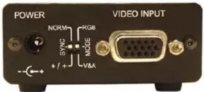
Figure 4
Use the Mode Dip Switch to select the video type for transmission.
The Sync Dip Switch is used to change the polarity of sync at the receiver. If your remote display has trouble positioning the right and left edges of the screen, then try putting the switch in the +/+ position.
VGA + Power Over UTP
4.0 Specifications
| Video Formats | RGB, and YPbPr, plus CV and line level stereo audio for UV1-SL | |
| Resolutions | Up to 1920 x 1440 non-interlaced at 60Hz | |
| Bandwidth DC to 250 MHz | ||
| Maximum Distance | Up to 500 ft. (152 meters) for VGA and Component Video models, or 2000 ft (609m) for Composite Video and Audio models | |
| Connectors | HD15 female for video input and output, RJ45 for CAT5 outputs | |
| Compliance CE; FCC Part 15 Subpart B Class A, IC Class | ||
| Power | From utility-power (mains) outlet, through included external Universal power supply. Output Voltage: 9 DC Center-Positive,Do not substitute any other external power supply without contacting the factory first. | |
| Dimensions | UV1-R | 0.8" H x 1.7" W x 4.5" L |
| UV1-S | 0.8" H x 1.7" W x 4.5" L | |
| UV1-R-DP | Single-gang Decora | |
| UV1-R-WP | 4.4" H x 2.8" W x 0.98" D | |
| UV1-S-DP | Single-gang Decora | |
| UV1-S-WP | 4.4" H x 2.8" W x 0.98" D | |
| UV1-SL | 1.1" H X 2.75" WxX 3.1" L | |
| UV1-SL-DP | Single-gang Decora | |
| UV2-S 1.22" H x 4.86"W x 2.60"D | ||
| UV4-S 1.22" H x 8.20" W x 3.00" D | ||
| UV8-S* | 1.32" H x 7.58" W x 3.88" D | |
*UV8-S has 2 L-shaped mounting ears that protrude 0.88" beyond the main box on each side. 4 mounting holes are present on a rectangular pattern of 8.62" x 2.63")
HR HALL RESEARCH
© Copyright 2012. Hall Research, Inc. All rights reserved.
CUSTOMER
SUPPORT
INFORMATION
Order toll-free in the U.S. 800-959-6439
FREE technical support, Call 714-641-6607 or fax 714-641-6698
Mail order: Hall Research, 1163 Warner Ave. Tustin, CA 92780
Web site: www.hallresearch.com E-mail: info@hallresearch.com
Brand : Hall Research
Model : UV1-S
Category : Audio/video extender