
PFM889-I/IM - Équipement sans fil Dahua Technology - Free user manual and instructions
Find the device manual for free PFM889-I/IM Dahua Technology in PDF.


| Product Type | Wireless Video Transmission Equipment |
| Brand | Dahua Technology |
| Model | PFM889-I/IM |
| CPU/Baseband | Atheros AR9344 |
| Memory | 64MB DRAM, 8MB Flash |
| Interfaces | 2 x 10/100M Base-TX (RJ-45) |
| Power Supply | POE (802.3af) or 24V/0.5A adapter |
| Wireless Standards | IEEE 802.11 a/n |
| Frequency Band | 4920-6100 MHz (5.8GHz band) |
| Max Data Rate | 300 Mbps |
| Max Transmission Distance | 3 km (point-to-point, line of sight) |
| Antenna | External directional antenna (included) |
| Operating Temperature | -30°C to 70°C |
| Operating Humidity | 5% to 95% (non-condensing) |
| IP Rating | IP66 |
| Security Features | WPA/WPA2, 802.1X, IP filtering, HTTPS/SSL, VLAN |
| Management | Web-based GUI, SNMP, Ping Watchdog, Reset button |
| Firmware | TDMA-based OS, upgradable |
| Warranty | Refer to manufacturer |
Frequently Asked Questions - PFM889-I/IM Dahua Technology
User questions about PFM889-I/IM Dahua Technology
0 question about this device. Answer the ones you know or ask your own.
Ask a new question about this device
Download the instructions for your Équipement sans fil in PDF format for free! Find your manual PFM889-I/IM - Dahua Technology and take your electronic device back in hand. On this page are published all the documents necessary for the use of your device. PFM889-I/IM by Dahua Technology.
USER MANUAL PFM889-I/IM Dahua Technology
DH-PFM Wireless Equipment
User's Manual
V1.0.0
ZHEJIANG DAHUA VISION TECHNOLOGY CO.,LTD.
Copyrights
© 2017 ZHEJIANG DAHUA VISION TECHNOLOGY CO.,LTD.. All rights reserved.
Any or full contents of the user's manual cannot be copied, transmitted, distributed or stored, partially or wholly, by any means, without the prior written approval of ZHEJIANG DAHUA VISION TECHNOLOGY CO.,LTD. (hereinafter "Dahua").
Dahua or a third party may reserve the right of the product described in this user's manual. Without the prior written approval of the corresponding party, any person cannot copy, distribute, amend, abstract, reverse compile, disassemble, decode, reverse engineering, rent, transfer or sub-license the software.
Trademark
@alhua @alhua @alhua HDCVI , , and are trademarks or registered
trademarks of the Dahua in various jurisdictions. Other trademarks and company names mentioned herein are the properties of their respective owners.
Update and Revision
In order to enhance the product safety and provide you with better user experience, Dahua may improve the product via software auto update, but Dahua doesn't need to inform in advance and isn't liable to any responsibility.
Dahua reserves the right to revise any information in this document at any time; the revised contents will be added into the new version without further notice. There may be minor differences in some product functions after it is updated.
Cybersecurity Statement
- You are responsible for the risks resulting from connecting your product to the internet, including but not limited to, cyber-attacks, hacking attacks, computer viruses and malware, etc. Please protect your data and personal information by taking necessary actions, such as changing the default password and using a strong combination, changing your password periodically, keeping your firmware up-to-date, etc. Dahua is not responsible for any dysfunction, information leakage or other problems caused by failure to take necessary precautions to secure your devices. We will provide product maintenance services.
- To the extent not prohibited by applicable laws, Dahua and its employees, licensees, and affiliates are not liable for personal injury, or any incidental, special, indirect, or consequential damages whatsoever, including, without limitation, damages for loss of profits, corruption or loss of data, failure to transmit or receive any data, business interruption, or any other commercial damages or losses arising out of or related to the use or inability to use its products or services, however caused, regardless of the theory of liability (contract, tort or otherwise), even if it has been advised of the possibility of such damages. Some jurisdictions do not allow the exclusion or limitation of liability for personal injury, or of incidental or consequential damages, so this limitation may not apply to you.
- In no event shall liability for all damages (other than as may be required by applicable laws in cases involving personal injury) exceed the amount paid for products or services.
Cybersecurity Recommendations
Mandatory actions to be taken towards cybersecurity
1. Change Passwords and Use Strong Passwords:
The number one reason systems get “hacked” is due to having weak or default passwords. Dahua recommends changing default passwords immediately and choosing a strong password whenever possible. A strong password should be made up of at least 8 characters and a combination of special characters, numbers, and upper and lower case letters.
2. Update Firmware
As is standard procedure in the tech-industry, we recommend keeping NVR, DVR, and IP camera firmware up-to-date to ensure the system is current with the latest security patches and fixes.
Check the firmware release of your running devices. If the firmware release date is over 18 months old, please contact a Dahua authorized local distributor or Dahua technical support for available update releases.
“Nice to have” recommendations to improve your network security
1. Change Passwords Regularly
Regularly change the credentials to your devices to help ensure that only authorized users are able to access the system.
2. Change Default HTTP and TCP Ports:
- Change default HTTP and TCP ports for Dahua systems. These are the two ports used to communicate and to view video feeds remotely.
- These ports can be changed to any set of numbers between 1025-65535. Avoiding the default ports reduces the risk of outsiders being able to guess which ports you are using.
3. Enable HTTPS/SSL:
Set up an SSL Certificate to enable HTTPS. This will encrypt all communication between your devices and recorder.
4. Enable IP Filter:
Enabling your IP filter will prevent everyone, except those with specified IP addresses, from accessing the system.
5. Change ONVIF Password:
On older IP Camera firmware, the ONVIF password does not change when you change the system's credentials. You will need to either update the camera's firmware to the latest revision or manually change the ONVIF password.
6. Forward Only Ports You Need:
- Only forward the HTTP and TCP ports that you need to use. Do not forward a huge range of numbers to the device. Do not DMZ the device's IP address.
- You do not need to forward any ports for individual cameras if they are all connected to a recorder on site; just the NVR is needed.
7. Disable Auto-Login on SmartPSS:
Those using SmartPSS to view their system and on a computer that is used by multiple people should disable auto-login. This adds a layer of security to prevent users without the appropriate credentials from accessing the system.
8. Use a Different Username and Password for SmartPSS:
In the event that your social media, bank, email, etc. account is compromised, you would not want someone collecting those passwords and trying them out on your video surveillance system. Using a different username and password for your security system will make it more difficult for someone to guess their way into your system.
9. Limit Features of Guest Accounts:
If your system is set up for multiple users, ensure that each user only has rights to features and functions they need to use to perform their job.
10. UPnP:
- UPnP will automatically try to forward ports in your router or modem. Normally this would be a good thing. However, if your system automatically forwards the ports and you leave the credentials defaulted, you may end up with unwanted visitors.
- If you manually forwarded the HTTP and TCP ports in your router/modem, this feature should be turned off regardless. Disabling UPnP is recommended when the function is not used in real applications.
11. SNMP:
Disable SNMP if you are not using it. If you are using SNMP, you should do so only temporarily, for tracing and testing purposes only.
12. Multicast:
Multicast is used to share video streams between two recorders. Currently there are no known issues involving Multicast, but if you are not using this feature, deactivation can enhance your network security.
13. Check the Log:
If you suspect that someone has gained unauthorized access to your system, you can check the system log. The system log will show you which IP addresses were used to login to your system and what was accessed.
14. Physically Lock Down the Device:
Ideally, you want to prevent any unauthorized physical access to your system. The best way to achieve this is to install the recorder in a lockbox, locking server rack, or in a room that is behind a lock and key.
15. Connect IP Cameras to the PoE Ports on the Back of an NVR:
Cameras connected to the PoE ports on the back of an NVR are isolated from the outside world and cannot be accessed directly.
16. Isolate NVR and IP Camera Network
The network your NVR and IP camera resides on should not be the same network as your public computer network. This will prevent any visitors or unwanted guests from getting access to the same network the security system needs in order to function properly.
For latest information about Dahua cybersecurity statement and recommendations, please visit www.dahuasecurity.com.
Overview
This document elaborates installation, configuration and use of DH-PFM wireless equipment.
Symbol Definition
The following symbols may appear in the document. Please refer to the table below for the respective definition.
| Symbol | Note |
 Danger Danger | It means highly potential danger. It will cause severe injury or casualties if it fails to avoid. |
 Waming Waming | It means moderate or low potential danger. It may cause slight or moderate injury if it fails to avoid. |
 Caution Caution | It means potential risk. It may cause device damage, data los weaker performance or other unpredictable consequences if it fails to avoid. |
 | It means that it can help you to solve a problem or save your time. |
 | It means the additional information, which is the emphasis and supplement of the main body. |
Before use, please read the following requirements carefully and conform to them strictly, in order to prevent danger and property loss.

Caution
- Please transport, use and store this product under allowed temperature and humidity.
- Please don't expose the product to direct sunlight or close to a heating source.
- Please don't place the product at humid, dusty or fuliginous places.
- Please install the product at well-ventilated places. Prohibit blocking its air vent.
- Please install the product at flat and stable places.
- Please don't drip or splash liquids onto the product.
- Please don't put other things onto the product.
- Please don't dismantle the product arbitrarily.

Warning
- Please use recommended power line within rated specifications.
Special Announcement
- This manual is for reference only. Please refer to the actual product for more details.
- This manual will be regularly updated according to product changes, and the updated contents will be added into the new version without prior announcement.
- Please contact Customer Service Department of this company for the latest program and supplementary instructions.
- The user shall undertake any losses resulting from violation of guidance in the manual.
- Regarding possible doubts or disputes in the manual, final explanations of the company shall prevail.
Legal Statement...... I
Cybersecurity Statement and Recommendations...... II
Preface....V
Important Safeguards and Warnings ...... VI
Description......VIII
1 Product Overview.... 1
1.1 Product Overview.... 1
1.2 Overview of TDMA Technology....3
1.3 Technical Features....4
1.4 Equipment Kit....5
1.5 Application Range 5
1.6 Hardware Profile 6
2 Product Installation....7
2.1 Equipment Installation....7
2.2 Description of Equipment Line Connection 9
2.3 Restore Factory Defaults 9
3 Common Networking 11
3.1 Wireless Point-to-point....11
3.2 Wireless Point-to-multipoint 12
3.3 Adjustment of Wireless Coverage Dead Angle.... 13
4 Status Display.... 14
5 Setting Wizard.... 17
6 Wireless Settings 23
7 Network Settings....26
8 Advanced Settings 29
9 System Settings 31
10 Tool Application....33
Appendix 1 Industry Application 35
Appendix 1.1 Wireless Surveillance of Safe Site....35
Appendix 1.2 Wireless Surveillance of Safe Town 38
Appendix 2 Troubleshooting....40
Appendix 3 Points for Attention ...... 42
Appendix 4 Test Report 44
Appendix 5 Technical Specification .... 50

Caution
Table 1 Release Note
| Version | Release Date | Revised Chapter | Author |
| 1.0 | 2014-05-12 | Create | cl |
Aim of Manual
This manual mainly enables users to get familiar with DH-PFM88X, helps users to use it and solve some common problems when necessary. This manual mainly involves DH-PFM88X hardware information, WEB page parameters, configuration mode, networking mode and fault analysis, so as to effectively help users to know and use the equipment quickly, and shorten the time for users to know DH-PFM series products.
Table 2 Definition of Nouns and Description of Abbreviations
| No. | Definition or Abbreviation | Description |
| 1 | DH-PFM880 | AP local side |
| 2 | DH-PFM881 | CPE client |
| 3 | DH-S4200-24T | Indoor switch without fan |
| 4 | DH-S4000-7X | Outdoor quasi-industrial switch with wide temperature range |
1 Product Overview
DH-PFM88X series equipment owns unique built-in TDMA wireless technology. This technology combines advanced core technologies in the industry, and boasts features such as long transmission distance, high throughput and strong anti-interference performance.
TDMA technology includes TDMA, flexible configuration of 5M/10M/20M/40MHz bandwidth, rate control and ACK overtime automatic adjustment technologies. TDMA effectively solves hidden node problem that perplexes large point-to-multipoint WLAN. Flexible configuration of 5M/10M/20M/40MHz bandwidth realizes balance between scarce wireless bandwidth resource and complicated working scenes. With advanced rate control algorithm, adapt to channel quality changes quickly while keeping stable rate as far as possible. ACK overtime automatic adjustment technology detects the distance between access point and client automatically, adjusts wireless parameters and optimizes the equipment performance.
DH-PFM881 maximum point-to-point transmission distance reaches 3km and maximum transmission rate reaches 300Mbps. With excellent remote transmission performance, its throughput rate reaches 40Mbps (open space) at 3km and multi-channel HD video can be transmitted. AP equipment supports point-to-point and point-to-multipoint remote access wireless mode; CPE supports point-to-point remote access mode.
1.1 Product Overview
With a small body, DH-PFM88X boasts the most advanced design technology in the industry, wireless transmission effect comparable to base station, and high cost performance advantage.
The equipment adopts unique TDMA wireless technology, integrates advanced TDMA, MIMO and Multi-hop technologies, innovative compatibility and improved 802.11n protocol, and thus guarantees long distance, throughput rate and anti-interference performance of wireless transmission. Compared to products of other manufacturers, DH-PFM88X series wireless equipment owns the following advantages:
1. Integrate TDMA Technology
DH-PFM88X owns TDMA operating system and integrates with TDMA technology, which effectively solves hidden node problem that perplexes large point-to-multipoint WLAN. With advanced rate control algorithm, adapt to channel quality changes quickly while keeping stable rate as far as possible, so it is very suitable for remote wireless transmission. By solving remote point-to-multipoint access issue, access quantity increases, rate allocation becomes more uniform, and it can be applied to operator and wireless surveillance fields.

Caution
As a wireless equipment operating system redeveloped on the basis of kernel, TDMA is more suitable for wireless video surveillance data transmission.
2. Integrate Watchdog
DH-PFM88X integrates hardware watchdog to monitor system operation all the time. In case of abnormal system operation, watchdog resets and reboots the system, so as to ensure its stability effectively and reduce manual operation.
3. Ping Watchdog Function Carries out Real-time Detection of Link
Ping Watchdog function detects whether the link fails or not, and reboots the equipment immediately when the link fails, so as to ensure link stability.
4. A Lot of Frequency is Provided to the User
At present, most wireless products work at standard 802.11 5.8G frequency, but standard 5.8G frequency band is relatively scarce. When 5.8G equipment is used a lot, it is easily interfered. DH-PFM88X increases support for frequency near 5.8G and expands working frequency to 4920MHz-6100MHz within allowed range. Since some frequencies face less interference, clients and access points in these frequency bands work better than other frequency bands. DH-PFM88X supports for non-standard frequency band has reduced external interference to wireless product, enhanced its throughput rate effectively and satisfied users' requirements for relatively high bandwidth.

Caution
Before using these non-standard frequency bands, please confirm whether they conform to local laws, regulations and radio management stipulations.
5. Adapt to Complicated and Changing Working Environment
DH-PFM88X is able to work in complicated and changing environment: working temperature ranges from -30°C to 70°C, while working humidity ranges from 5% to 95%. DH-PFM88X keeps relatively high throughput rate in all kinds of harsh environment for a long time, such as thunderstorm, high temperature and high humidity, low temperature and low humidity.
1.2 Overview of TDMA Technology
At present, most remote Wi-Fi network bridge products have developed from 802.11 WLAN technology. Built-in TDMA operating system integrates TDMA, flexible configuration of 5M/10M/20M/40MHz bandwidth, rate control and ACK overtime automatic adjustment technologies, and it is known as an ideal remote Wi-Fi access product. TDMA effectively solves hidden node problem that perplexes large point-to-multipoint WLAN. Flexible configuration of 5M/10M/20M/40MHz bandwidth realizes balance between scarce wireless bandwidth resource and complicated working scenes: narrow wireless bandwidth configuration is used when there are less idle wireless channels and single user doesn't place a high requirement on wireless access rate; wide wireless bandwidth configuration is used when there are many idle wireless channels and single user places a high requirement on wireless access rate. Moreover, narrow wireless bandwidth configuration is more effective in sheltered environment. With advanced rate control algorithm, adapt to channel quality changes quickly while keeping stable rate as far as possible, so it is very suitable for remote wireless transmission. ACK overtime automatic adjustment technology detects the distance between access point and client automatically, adjusts wireless parameters and optimizes the equipment performance.
Before AP enables TDMA, client shall set a priority. When one AP connects multiple clients and different clients place different requirements on bandwidth, priority shall be set according to bandwidth requirements of client on present equipment. In case of high bandwidth requirements, it is suggested that the priority should be set to be high; on the contrary, the priority should be set to be low. Of course, if all clients place the same requirements on bandwidth, priority of all clients can be the same

Caution
TDMA function can be enabled by AP; client can set its own priority. Other manufacturers' TDMA cannot intercommunicate with our TDMA.
1.3 Technical Features
1) Integrate TDMA and effectively enhance "point-to-multipoint" overall performance.
2) Support client priority setting and better deploy every client in case of point-to-multipoint.
3) Support Ping Watchdog and real-time monitoring of wireless link; reboot the equipment automatically when wireless link disconnects, and thus ensure its stability.
4) Support outdoor high temperature and low temperature: -30-70°; quasi-industrial design, waterproof IP66 grade.
5) Recommended wireless coverage range is 3km.
6) Lightning protection of radio frequency port reaches 15KV ESD.
7) Support automatic distance measurement function; display straight-line distance between client and base station in a real-time way.
8) Support automatic rebooting and restoration function of the equipment.
9) Full-band support: frequency spreading supports 4920\~6100Mhz.
10) Support flow control; control input/output flow of base station/client effectively.
11) Support VLAN division, realize VLAN function and control broadcast storm.
12) Support 802.1x authentication method, ensure client access control effectively and provide access security.
13) Support multi-channel selection (5M/10M/20M/40M); promote anti-interference and penetrating power effectively.
14) Support 4 working modes: AP, Station, AP-WDS and Station-WDS.
15) Unique design of antenna radio-frequency amplifier and low-noise receiver guarantees remote video, audio and data transmission.
16) Human-oriented working mode wizard configuration is convenient for those who are not wireless professionals.
17) POE power supply supports international 802.3af standard, and becomes more convenient and
reliable.
18) Support IP login, carry out remote control and management via webpage, and thus facilitate configuration.
19) Waterproof ultraviolet-proof shell ensures that the equipment works stably outdoors.
1.4 Equipment Kit

| No. | DH-PFM880 | DH-PFM881 |
| 1 | Host*1 | Host*1 |
| 2 | Antenna*1 | N/A |
| 3 | Feeder*2 | Cable tie *2 |
| 4 | POE power supplier (24V/0.5A)*1 | POE power supplier (24V/0.5A)*1 |
| 5 | Instruction book | Instruction book |
| 6 | Other installation packages | Other installation packages |
Table 1-1 Packing List
1.5 Application Range
- First-choice recommendation: safe town, safe construction site, safe scenic area, elevator IP HD wireless video surveillance.
Secondary recommendation: unblocked scenes such as playground, pasture and suburb crossroad.
1.6 Hardware Profile
| Hardware Index | |
| CPU/Baseband Radio | Atheros AR9344 |
| Memory | 64MB DRAM, 8MB Flash |
| Physical Interface | 2×10/100M Base-TX (Cat. 5/5E, RJ-45) network interface |
| LED Indicator Light | Power, LAN, WLAN, 3×Link Quality |
| Power Supply | POE, Power Adapter 24V/0.5A |
Table 1-2 Hardware Information
Description of LED Mechanism
DH-PFM88X adopts LED to display present working status and connecting quality, so users know its present working condition visually without logging onto the webpage. LED mainly consists of two parts, equipment status and connecting quality. The first LED in the left is power indicator light, the second one in the left is network indicator light and the third one is connection indicator light. The first one to the third one in the right is signal strength indicator light.


Figure 1-1 LED Indicator Light on DH-PFM881 Shell
| LED | Color | Status |
| POWER | Green | When this light turns on, it means that DH-PFM88X is connected with power supply. |
| LAN | Green | When this light turns on, it means that DH-PFM88X LAN port is connected with external equipment. |
| WLAN | Green | When this light turns on, it means that DH-PFM88X wireless is enabled.When this light flickers, it means that equipment wireless is enabled, and data is wirelessly transmitted. |
| Signal Strength | Red | Indicator light shows signal strength.Green light means high signal strength. |
| Yellow | Yellow light means medium signal strength. | |
| Green | Red light means very weak signal or no signal. |
Table 1-3 LED Information
2 Product Installation
2.1 Equipment Installation
natural_image
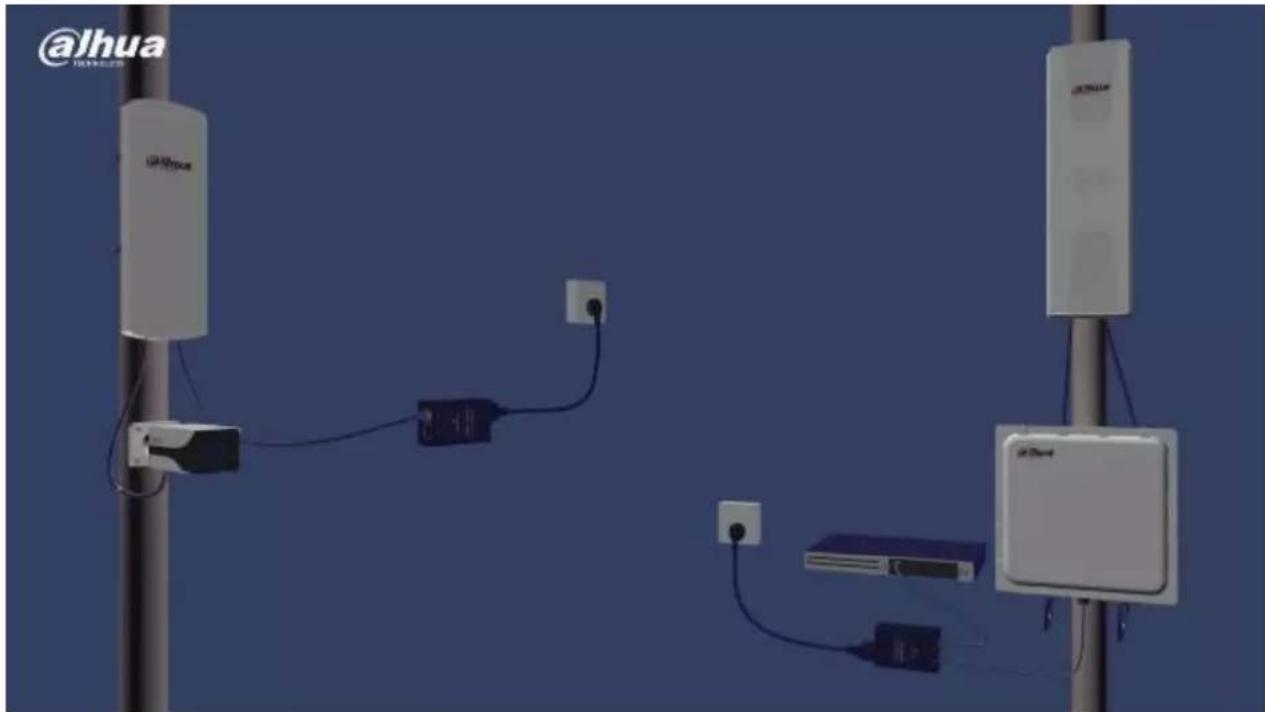
3D rendering of a network device setup with two vertical posts and connected cables, no visible text or symbolsFigure 2-1 DH-PFM88X Overall Installation Diagram

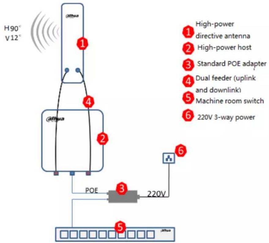
DH-PFM88X line connection type differs under different network modes. Since its default setting is network bridge mode, this chapter mainly describes line connection type of network bridge mode. For connection type of route mode, please refer to Chapter 7 Route Mode of Network Setting.
flowchart
graph TD
    A["@lthua"] -->|1| B["POE"]
    A -->|2| C["220V 3-way power"]
    A -->|3| D["220V 3-way power"]
    A -->|4| E["220V 3-way power"]
    A -->|5| F["220V 3-way power"]
    G["High-power directive antenna"] --> A
    H["High-power host"] --> A
    I["Standard POE adapter"] --> A
    J["Dual feeder (uplink and downlink)"] --> A
    K["Machine room switch"] --> A
    L["220V 3-way power"] --> A
Figure 2-2 DH-PFM880 Installation Diagram

Figure 2-3 DH-PFM881 Installation Diagram
2.2 Description of Equipment Line Connection
flowchart
graph TD
    A["DH-PFM88X"] -->|POE| B["POE Power"]
    A -->|LAN2| B
    A -->|Camera| B
    B -->|POE| C["PC Host/Camera"]
    B -->|LAN| D["Network Cable"]
    D --> E["Output"]
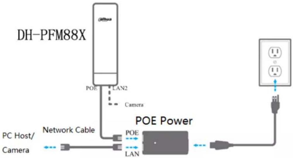
Figure 2-4 DH-PFM88X Interface Connection Diagram
| Type | Interface | Interface Name | Connection and Function |
| DH-PFM881 | Two RJ45 interfaces | POE | Connect “POE” on POE power supply with twisted pair cable; provide DH-PFM881 equipment with 24V power supply and data transmission. |
| LAN2 | As “LAN” interface, it can connect IF Camera. Any LAN port can be used for equipment debugging. | ||
| DH-PFM880 | One RJ45 interface | None | Connect “POE” interface on POE power supply with network cable; provide DH-PFM880 equipment with 24V power supply and data transmission. “LAN” interface on POE power supply connects a switch or other equipment, and serves as a debugging interface. |
Table 2-1 Description of Port Connection
2.3 Restore Factory Defaults
If the user forgets DH-PFM88X IP, choose manual operation: press Reset key for 5-10s and release it after all LED turn on, when the equipment has restored factory defaults. Meanwhile, the network interface, which owns a direct connection with DH-PFM88X host, displays 2 continuous connections and disconnections.

Figure 2-5 Restore Factory Defaults
| Item | Factory Defaults |
| IP Address | 192.168.1.36 |
| User Name | admin |
| Password | admin |
| Wireless Mode | Client |
| Encryption Type | WPA->WPA2->CCMP->secret key: 1234567890abc |
| Network Mode | Network bridge mode |
Table 2-2 Factory Defaults of Main Parameters

Caution
At network management page of the equipment (System Settings), click “Restore” and restore factory defaults. Factory parameters are shown in Table 2-2 Factory Defaults of Main Parameters.
3 Common Networking
3.1 Wireless Point-to-point
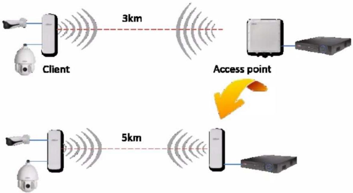
During point-to-point communications, one DH-PFM881 is usually set to be an access point, while the other DH-PFM881 equipment is the client. Actual connection diagram is as follows.
flowchart
graph TD
    A["Client"] -->|3km| B["Server"]
    B --> C["Access point"]
    D["Client"] -->|5km| E["Server"]
    E --> F["Access point"]
Figure 3-1 Networking Diagram of Access Point and Client
- At Network Settings Page->Network Mode, both DH-PFM88X equipment shall be set to network bridge mode; firewall is prohibited in both equipment; they have different LAN IP.
- At Wireless Page, wireless mode shall be set to be access point and client respectively. AP and client have the same SSID, the same encryption way and password. For example, WPA->WPA2->CCMP->1234567890. Output power is set to be 13dBm, AP frequency is 5.785GHz, whereas channel width of AP and client is 20MHZ.
- Caution: directions of AP and client shall be opposite.
- One computer pings the other computer. That is to say, input ping xxx.xxx.xxx.xxx (IP of the other computer) on one computer.
Expected result: after AP and client are connected, computers of AP and client can ping with each other. Meanwhile, connection quantity is 1 on AP status display page.
3.2 Wireless Point-to-multipoint
During point-to-multipoint communications, DH-PFM880 is usually set to be an access point (single AP covers 90 degrees and 4 AP cover 360 degrees), while other DH-PFM881 equipment shall be client. Actual connection diagram is as follows.

Figure 3-2 Point-to-multipoint Networking Diagram
- At Network Settings Page->Network Mode, all DH-PFM88X equipment shall be set to network bridge mode; firewall is prohibited (which is disenabled by default) in all equipment; they have different LAN IP.
- At Wireless Page, wireless mode shall be set to be access point and client respectively. AP and client have the same SSID, the same encryption way and password. For example, WPA->WPA2->CCMP->1234567890. It is suggested that configuration should be completed according to equipment wizard.
- Caution: directions of AP and client shall be opposite.
- One computer pings the other computer. That is to say, input ping xxx.xxx.xxx.xxx (IP of the other computer) on one computer.
Expected result: after AP and client are connected, computers of AP and client can ping with each other.
Meanwhile, connection quantity is N (representing the quantity of connected clients) on AP status display page.
3.3 Adjustment of Wireless Coverage Dead Angle
When client adopts direct wireless communications with central AP (access point) because surveillance point is blocked seriously, two sets of CPE realize back-to-back connection and carry out angle adjustment. Actual connection diagram is as follows.

flowchart
graph TD
    A["Client"] -->|5km| B["Access point"]
    B -->|3km| C["Monitor"]
    C --> D["Server"]
    style A fill:#f9f,stroke:#333
    style B fill:#ccf,stroke:#333
    style C fill:#cfc,stroke:#333
    style D fill:#fcc,stroke:#333
Figure 3-3 Networking Diagram of Coverage Dead Angle Adjustment
1. Two back-to-back equipment shall adopt wired connection.
2. Downlink client equipment is set to be access point; uplink central AP equipment is set to be client.
3. For specific configuration of single equipment, please refer to setting wizard configuration.
| Network Bridge | Equipment | Mode | Frequency (MHz) | Network Name | Password |
| A&B Pairing | A | Client | Default | Dahua1 | Dahautech1 |
| B | AP | 5745MHz(149) | Dahua1 | Dahautech1 | |
| C&D Pairing | C | Client | Default | Dahua2 | Dahautech2 |
| D | AP | 5825MHz(165) | Dahua2 | Dahautech2 |
Corresponding Table of Pairing Across Network

By default, client doesn't need to set equipment frequency, but differentiates by e and password. High-end user can set client input frequency at wireless setting page.
As the first page after the user logs on, status display page shows present configuration of the equipment and real-time monitoring of present working status. It is the 2^nd item of menu bar.

Figure 4-1 Status Display
| Item | Function | Item | Function |
| Name | DH-PFM88X | Kernel Version | V2.1.0.2681.9344 |
| Firmware Version | Software version number | 802.11 Mode | Conform to 802.11 protocol at present |
| WAN IP | IP address of WAN port in route mode | WAN MAC | MAC address of WAN port in route mode |
| Network Mode | Operation mode, route mode or network bridge mode | Network Name | Name of wireless network |
| Frequency/ Channel | Communications channel | Channel Width | There are 4 types, including 5M, 10M, 20M and 20/40M AUTO. |
| Wireless Mode | Client, AP, WDS client, WDS AF and WDS repeater | Encryption | Several encryption methods of wireless network |
| Distance | Distance between interconnected client and AP | Noise Floor | Interference from external environment |
| Signal | As a parameter for client, WDS | Link | Link connection quality |
| Level | client and WDS repeater, it shows overall signal level of client, as well as uplink and downlink signal level of client. | Quality | |
| TX/RX Rate | As a parameter for client, WDS client and WDS repeater, it shows momentary rate of transmitting/receiving data of present equipment. | Time | It displays time. When NTP client function is enabled, NTP server is set correctly and the equipment is online, the time item will be automatically updated to calibration time on NTP server. If it cannot go online, it has a default value. |
Table 4-1 Parameters on Status Display Page
Real-time Monitoring
Throughput rate: also known as throughput capacity, it refers to data size passing every section within unit time. Throughput rate on status display page refers to data size transmitted on the network within unit time. This is a main index to measure network performance. With this index, the user can monitor data transmission speed of the equipment.

line
| Throughput | Routes Table | Bridge Table | ARP Table | AP Information | Syslog | | ---------- | ------------ | ------------ | --------- | -------------- | ------ | | RX | 6.11kbps | | | | | | TX | | 648kbps | | | |Figure 4-2 Throughput Rate
Routes table: it stores the path pointing to network of DH-PFM88X equipment.
| Monitor | Throughput | Routes Table | Bridge Table | ARP Table | AP Information | Syslog | |||
| Destination | Gateway | Netmask | Interface | |
| 192.168.1.0 | * | 255.255.255.0 | br0 | |
Figure 4-3 Routes Table
Bridge table: corresponding relation of MAC address and aging time of equipment whose communication has gone through DH-PFM88X in the past certain period, obtained by DH-PFM88X.
| Monitor | Throughput | Routes Table | Bridge Table | ARP Table | Station Information | Syslog | |
| MAC Address | Ageing Timer | |
| 08:9e:01:bb:a2:8b | 0.50 | |
| 9c:b7:93:de:d9:2b | 0.00 | |
| 9c:b7:93:e0:d9:2b | 0.00 | |
Figure 4-4 Bridge Table
ARP table: corresponding relation of IP address and MAC address used by LAN port, whose communication has gone through DH-PFM88X in the past certain period, obtained by the equipment.
| Monitor | Throughput | Routes Table | Bridge Table | ARP Table | Station Information | Syslog | ||
| IP Address | MAC Address | Interface | |
| 192.168.1.11 | 08:9e:01:bb:a2:8b | br0 | |
Figure 4-5 ARP Table
AP/Client Information Table
When the equipment connects a client in AP mode, it shows client information.
| Monitor | Throughput | Routes Table | Bridge Table | ARP Table | Station Information |
| MAC Address | TX/RX Rate | RSSI | |||
| 9c:b7:93:e0:40:69 | 216M/240M | 65 |
Figure 4-6 Client Information
When the equipment connects an AP in client mode, it shows AP information.
| Monitor | Throughput | Routes Table | Bridge Table | ARP Table | AP Information | Syslog | ||||||
| MAC Address | TX/RX | Signal Level | Noise Floor | RX Packets | TX Packets | RX Bytes | TX Bytes |
| 9c:b7:93:d2:05:bc | 240M/240M | -27 | -96 | 4877 | 1063943 | 3131930 | 39917838 |
Figure 4-7 AP Information
Precondition
Connect the equipment with configuration host and turn on power by reference to Figure 2-4 DH-PFM88X Interface Connection Diagram.
Operating Steps
Step 1 Configure static IP address of "192.168.1.x" segment of host IP address (for example, 192.168.1.180).

Figure 5-1 Host IP
Step 2 In the browser, input default IP address of DH-PFM88X: 192.168.1.36. The system shows login page.

Figure 5-2 Login Page
Step 3 Input username and password (whose default values are admin), and click "Confirm". The system shows status display page, including basic information, such as working status, present settings and software version of DH-PFM88X equipment.

Figure 5-3 Status Display
Step 4 Click "Wizard" in the left, which helps the user to configure the equipment quickly, such as network configuration and wireless mode and so on.
You can click menu in the left of the page, to enter corresponding configuration page.
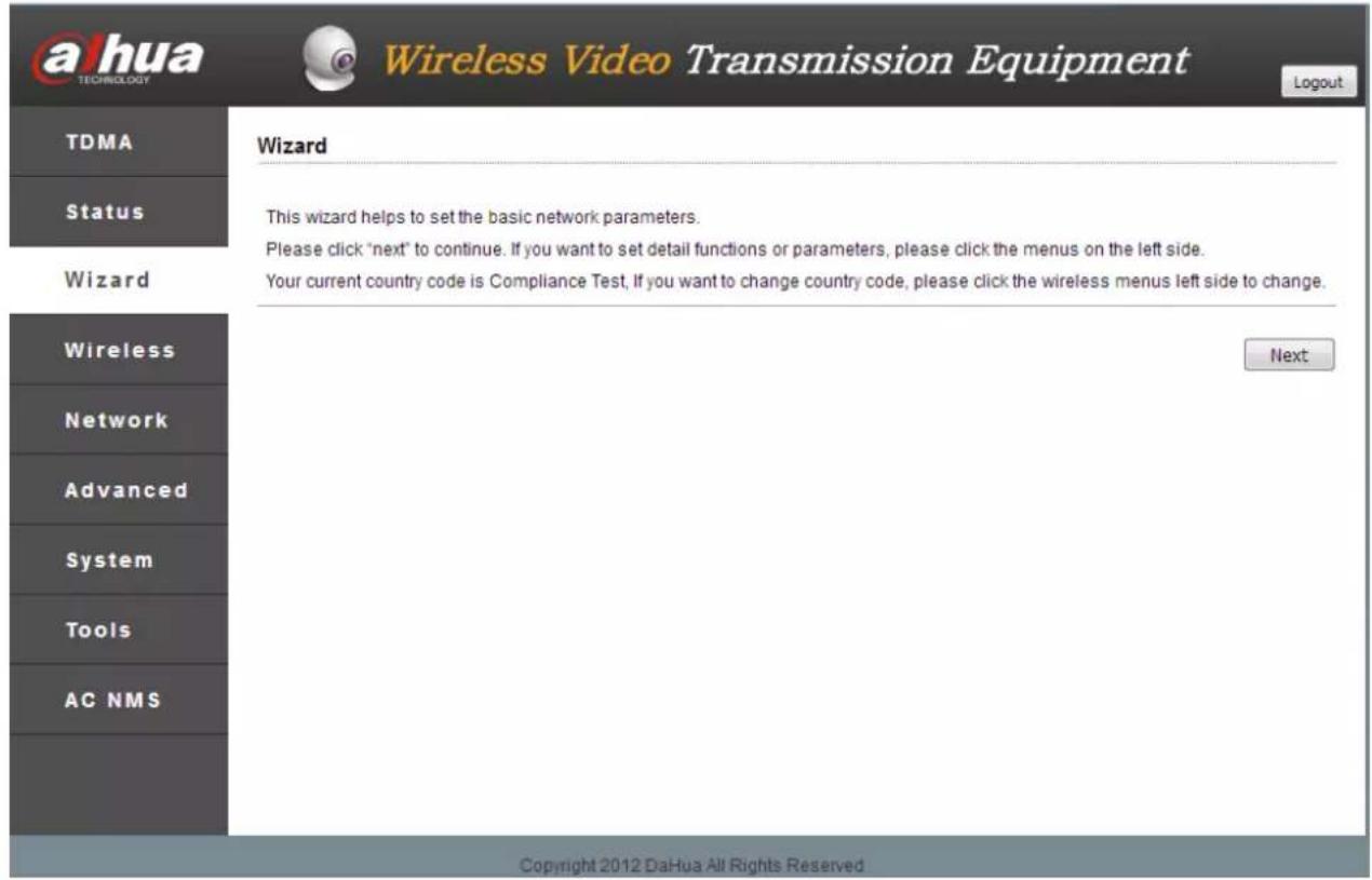
Figure 5-4 Wizard
Step 5 Click "Next" to show basic network parameters. Default configuration is "Network Bridge Mode"; IP address of LAN port is "192.168.1.36". It is suggested that the user should modify its IP address immediately after logging onto the equipment.

Equipment IP is unique in the same LAN. Pay attention to modify equipment IP according to design, and ensure that IP in the same LAN doesn't conflict.

Figure 5-5 Network Setting
Step 6 Click "Next" to show basic wireless parameters and wireless encryption options.
The most common two wireless modes of DH-PFM88X equipment are “client” and “access point”. In the same LAN, local end and client wireless equipment have the same needs for wireless encryption option, network name option and password option.
Note
- In "client" mode, equipment connecting video camera is usually set as client mode.
- In “access point” mode, local DH-PFM88X equipment is usually set as access point mode, connecting surveillance room.
- In case of multiple access points in the same region, pay attention to set different frequencies for different DH-PFM880 equipment; choose one from 8 defined frequencies.
![ahua TECHNOLOGY Wireless Video Transmission Equipment Logout TDMA Status Wizard Wireless Network Advanced System Tools AC NMS Wireless This wizard page helps to set the basic wireless and wireless security. Please click the left "Wireless" menu for detail setting. Wireless Mode: Station SSID: DaHua Wireless Security[?]: WPA WPA2-PSK Key: •••••••••••••••••••••••••••••••••••••••••••••••••••••••••••••••••••••••••••••• Last Next Copyright 2012 DaHua All Rights Reserved](/content/2026/05/893400/images/7d7ffef532decad3e7811a5fb5c8bf38f500d15a2fa6b44211520c6bb8708cf8.jpg)
Figure 5-6 Wireless Setting
Step 7 Click "Next" to show working scenario option.
This wizard provides custom scenarios for the user, as is shown in the following figure. It is suggested that default settings should be used.
![ahua TECHNOLOGY Wireless Video Transmission Equipment Logout TDMA Status Wizard Wireless Network Advanced System Tools AC NMS Scenario This wizard page helps to select the working scenarios. The first 3 working scenarios cover most of the cases. Please click Custom t o manually set the parameters. Long distance (>1Km) [?] +Line of sight Long distance (>1Km) [?] +None line of sight Short distance (<1Km) [?] Custom [?] Last Next Copyright 2012 DaHua All Rights Reserved](/content/2026/05/893400/images/3f0dd71cef436a3c19e2270b9a549195fa3d0f72e5986979479474f518a7d69f.jpg)
Figure 5-7 Working Scenario
Step 8 Click "Next" to show custom scenarios.
- When wireless mode is access point, the user only needs to change channel width to be 40+MHz or 40-MHz, set output power at 27dBm and tick "ACK-Timeout Adjustment". Other options remain unchanged.
- When wireless mode is client, the user shall set channel at 20/40M, output power at 27dBm and tick "ACK-Timeout Adjustment". Other options remain unchanged.

Figure 5-8 Custom Scenario
| Parameter Name | Parameter Description |
| Output Power | The user configures output power of the equipment according to actual working conditions and local laws. The larger the output power is, the farther the wireless transmission distance will be (maximum output power available to the system is 27dBm). |
| Channel Width | Default value is 20MHz, so as to reach the optimal wireless transmiss rate. It is suggested that channel width should be 40+MHz or 40-MHz, so as to enhance wireless transmission quality. |
| ACK-Timeout Adjustment | It is suggested that the user should enable “ACK-Timeout Adjustment”. This option tests the distance between two equipment automatically, sets parameters according to this distance and thus optimizes wireless connection quality. |
| Distance | If “ACK-Timeout Adjustment” is enabled, this distance setting becomes invalid; the system will test equipment distance automatically and optimize connection quality. “ACK-Timeout Adjustment” shall be disenabled, so that the distance set by the user takes effect. |
Table 5-1 Parameter Description
Step 9 Click "Next" to show "Wizard-Finish" page.
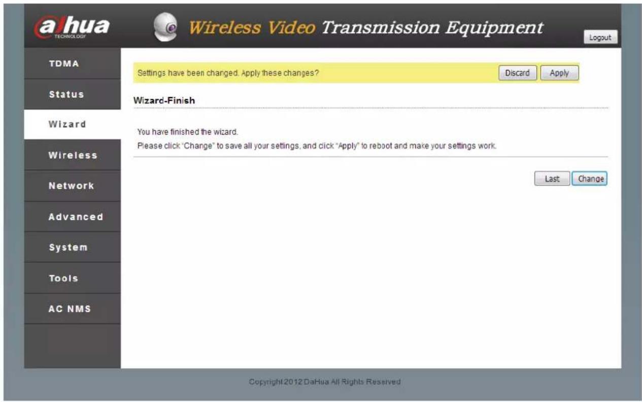
Figure 5-9 Finish Page
Step 10 Click "Change" button to save all settings, and then click "Apply" button, so as to make them take effect.
You can click "Last" to change previous settings.
Page of wireless settings is shown as follows:
![a hua TECHNOLOGY Wireless Video Transmission Equipment Logout TDMA Status Wizard Wireless Network Advanced System Tools AC NMS Basic Wireless Settings Wireless Mode[?]: Station SSID: DaHua Select Frequency Scan List[?]: Enable Output Power: 27 dBm IEEE 802.11 Mode: A/N mixed Country Code: Compliance Test Select Channel Width[?]: 20/40 MHz Max TX Rate, Mbps[?]: MCS 15-300 Wireless Security Settings Security: WPA Mode: WPA 2 Cypher: CCMP Authentication Mode: PSK WPA Key: Show Change Copyright 2012 DaHua All Rights Reserved](/content/2026/05/893400/images/be7299e89d7f68eee76f749dadb8d5d199b2d060e7c790c9a6cc83c97b15500b.jpg)
Figure 6-1 Wireless Settings
There are 5 wireless modes, including AP mode, CPE/client mode, WDS client mode, WDS AP mode and WDS repeater.
Access Point (AP) mode: a wireless access node can be connected with client equipment, such as computer, mobile phone and wireless bridge etc.. One AP is able to connect with multiple clients.
CPE/Client: it is used with AP. One client only connects with one AP.
WDS Client: equivalent to client, it only connects with WDS AP or WDS repeater. One WDS client only connects with one WDS AP or WDS repeater.
- DH-PFM Wireless Equipment
- User's Manual
- Copyrights
- Trademark
- Update and Revision
- Cybersecurity Statement
- Cybersecurity Recommendations
- Change Passwords and Use Strong Passwords:
- Update Firmware
- Change Passwords Regularly
- Change Default HTTP and TCP Ports:
- Enable HTTPS/SSL:
- Enable IP Filter:
- Change ONVIF Password:
- Forward Only Ports You Need:
- Disable Auto-Login on SmartPSS:
- Use a Different Username and Password for SmartPSS:
- Limit Features of Guest Accounts:
- UPnP:
- SNMP:
- Multicast:
- Check the Log:
- Physically Lock Down the Device:
- Connect IP Cameras to the PoE Ports on the Back of an NVR:
- Isolate NVR and IP Camera Network
- Overview
- Symbol Definition
- Caution
- Warning
- Special Announcement
- Aim of Manual
- Product Overview
- Product Overview
- Integrate TDMA Technology
- Integrate Watchdog
- Ping Watchdog Function Carries out Real-time Detection of Link
- A Lot of Frequency is Provided to the User
- Adapt to Complicated and Changing Working Environment
- Overview of TDMA Technology
- Technical Features
- Equipment Kit
- Application Range
- Hardware Profile
- Description of LED Mechanism
- Product Installation
- Equipment Installation
- Description of Equipment Line Connection
- Restore Factory Defaults
- Common Networking
- Wireless Point-to-point
- Wireless Point-to-multipoint
- Adjustment of Wireless Coverage Dead Angle
- Corresponding Table of Pairing Across Network
- Real-time Monitoring
- AP/Client Information Table
- Precondition
- Operating Steps
- Note
Brand : Dahua Technology
Model : PFM889-I/IM
Category : Équipement sans fil