
XVR5108H-4KL-I2 - Digital Video Recorder Dahua Technology - Free user manual and instructions
Find the device manual for free XVR5108H-4KL-I2 Dahua Technology in PDF.


| Product Type | Digital Video Recorder (DVR) |
| Model | XVR5108H-4KL-I2 |
| Brand | Dahua Technology |
| Video Compression | H.265, H.264, MJPEG |
| Video Input Channels | 8 channels (analog/HD) |
| Video Output | HDMI, VGA, CVBS (simultaneous) |
| HDMI Resolution | Up to 4K (3840 x 2160) |
| Audio Input/Output | 16-channel audio input via DB25, 1-channel output plus two-way talk |
| Alarm I/O | 16 alarm inputs, 3 alarm outputs (NO/NC) |
| Network Interface | 1 RJ-45 10/100/1000 Mbps Ethernet |
| PTZ Control | RS-485, supports multiple protocols |
| AI Functions | Face detection, face recognition, IVS (tripwire, intrusion), human/vehicle detection |
| Recording | Continuous, scheduled, motion, alarm, AI event recording |
| Playback | Simultaneous record and playback, smart search, frame-by-frame, reverse play |
| Storage | 1 SATA HDD up to 10TB, eSATA support |
| USB Ports | 2 USB 2.0 ports on front and rear |
| Power Supply | 12 VDC, 3.5A (standard) |
| Power Consumption | < 15W (without HDD) |
| Operating Temperature | -10°C to +55°C (14°F to 131°F) |
| Operating Humidity | 10% – 90% (non-condensing) |
| Dimensions (W x D x H) | Approx. 315 x 250 x 48 mm |
| Weight | Approx. 1.5 kg (without HDD) |
| Mounting | Desktop or rackmount (bracket optional) |
| Included Accessories | Mouse, power adapter, CD (manual and software), screws for HDD |
Frequently Asked Questions - XVR5108H-4KL-I2 Dahua Technology
User questions about XVR5108H-4KL-I2 Dahua Technology
0 question about this device. Answer the ones you know or ask your own.
Ask a new question about this device
Download the instructions for your Digital Video Recorder in PDF format for free! Find your manual XVR5108H-4KL-I2 - Dahua Technology and take your electronic device back in hand. On this page are published all the documents necessary for the use of your device. XVR5108H-4KL-I2 by Dahua Technology.
USER MANUAL XVR5108H-4KL-I2 Dahua Technology

ZHAOANG GUANJIAN VIEW TECHNOLOGY CO., LTD. 102.3.03
Foreword
General
This user's manual (hereinafter referred to be "the Manual") introduces the functions and operations of the DVR devices (hereinafter referred to as "the Device"). Read carefully before using the device, and keep the manual safe for future reference.
Safety Instructions
The following signal words might appear in the manual.
Signal Words Meaning
| DANGER | Indicates a high potential hazard which, if not avoided, will result in death or serious injury. |
| WARNING | Indicates a medium or low potential hazard which, if not avoided, could result in slight or moderate injury. |
| CAUTION | Indicates a potential risk which, if not avoided, could result in property damage, data loss, reductions in performance, or unpredictable results. |
| IPS | Provides methods to help you solve a problem or save time. |
| NOTE | Provides additional information as a supplement to the text. |
Revision History
| Version | Revision Content | Release Time |
| Added DH-XVR54xxL-4KL-I3, DH-XVR58xxS-4KL-I3, DH-XVR58xxS-4KL-I3-LP, DH-XVR71xxH-4K-I3, DH-XVR71xxHE-4K-I3, DH-XVR72xxA-4K-I3, DH-XVR72xxAN-4K-I3, DH-XVR74xxL-4K-I3, and DH-XVR78xxS-4K-I3. | July 2022 | |
| V2.3.0 | ||
| V2.2.0 | Added the configuration of extended smart illumination. | June 2022 |
| V2.1.0 | Added DH-XVR54xxL-I3 and DH-XVR58xxS-I3. | May 2022 |
| Version | Revision Content | Release Time |
| V2.0.0 | Added DH-XVR42xxAN-I(V2.0).Added smart illumination as alarm linkage.Added schedule mode for AI functions.Added IVS mode switch.Added disabling event notifications in disarming.Added sensitivity for IVS settings.Updated disk quota.Supports safety baseline 2.0. | April 2022 |
| V1.2.1 | Updated AI mode switch.Added intelligent diagnosis.Updated alarm-in port settings.Updated password resetting. | December 2021 |
| V1.2.0 Added some models. | October 2021 | |
| V1.1.0 | Added DH-XVR4232AN-I. | July 2021 |
| V1.0.11 | Added DH-XVR5816S-4KL-I2-LP and DH-XVR7816S-4KL-X-LP-V2. | May 2021 |
| V1.0.10 Deleted the video quality analytics function. | April 2021 | |
| V1.0.9 Added some models. | February 2021 | |
| V1.0.8 Added some models. | November 2020 | |
| V1.0.7 Added some models. | September 2020 | |
| V1.0.6 Added some models. | May 2020 | |
| V1.0.5 | Updated to 4.0 UI version. | February 2020 |
| V1.0.4 | Added disarm function, HDD database function, and SMD preview function.Optimizes Smart Search function, available to filtering human and vehicle. | September 2019 |
| V1.0.0 | First release. | October 2018 |
Privacy Protection Notice
As the device user or data controller, you might collect the personal data of others such as their face, fingerprints, and license plate number. You need to be in compliance with your local privacy protection laws and regulations to protect the legitimate rights and interests of other people by implementing measures which include but are not limited: Providing clear and visible identification to inform people of the existence of the surveillance area and provide required contact information.
About the Manual
- The manual is for reference only. Slight differences might be found between the manual and the product.
- We are not liable for losses incurred due to operating the product in ways that are not in compliance with the manual.
- The manual will be updated according to the latest laws and regulations of related jurisdictions. For detailed information, see the paper user's manual, use our CD-ROM, scan the QR code or visit our official website. The manual is for reference only. Slight differences might be found between the electronic version and the paper version.
- All designs and software are subject to change without prior written notice. Product updates might result in some differences appearing between the actual product and the manual. Please contact customer service for the latest program and supplementary documentation.
- There might be errors in the print or deviations in the description of the functions, operations and technical data. If there is any doubt or dispute, we reserve the right of final explanation.
- Upgrade the reader software or try other mainstream reader software if the manual (in PDF format) cannot be opened.
- All trademarks, registered trademarks and company names in the manual are properties of their respective owners.
- Please visit our website, contact the supplier or customer service if any problems occur while using the device.
- If there is any uncertainty or controversy, we reserve the right of final explanation.
Important Safeguards and Warnings
This chapter describes the contents covering proper handling of the Device, hazard prevention, and prevention of property damage. Read carefully before using the device, and comply with the guidelines when using it.
Operation Requirements
- Do not place or install the Device in a place exposed to sunlight or near the heat source.
- Keep the Device away from dampness, dust or soot.
- Keep the Device installed horizontally on the stable place to prevent it from falling.
• Wall-mounting is not supported. - Do not drop or splash liquid onto the Device, and make sure there is no object filled with liquid on the Device to prevent liquid from flowing into the Device.
● Install the Device in a well-ventilated place, and do not block the ventilation of the Device. - Operate the device within the rated range of power input and output.
- Do not dissemble the Device.
● Transport, use and store the Device under the allowed humidity and temperature conditions.
Electrical Safety
- Use the battery of specified manufacturer; otherwise there might result in explosion. When replacing battery, make sure the same type is used. Improper battery use might result in fire, explosion, or inflammation.
- Follow the instructions to dispose of the used battery.
- Use the recommended power cables in the region and conform to the rated power specification.
- Use the power adapter provided with the Device, or adapter meets the LPS standard; otherwise, it might result in people injury and device damage.
- The power supply must conform to the requirements of ES1 in IEC 62368-1 standard and be no higher than PS2. Note that the power supply requirements are subject to the device label.
- Connect the device (I-type structure) to the power socket with protective earthing.
- The appliance coupler is a disconnection device. When using the coupler, keep the angle for easy operation.
Table of Contents
Foreword....II
Important Safeguards and Warnings......V
1 Introduction.... 1
1.1 Overview ...... 1
1.2 Functions....1
2 Getting Started.... 3
2.1 Checking the Components .... 3
2.2 Installing HDD .... 3
2.2.1 DH-XVR42xxAN-I/DH-XVR42xxAN-I(V2.0)/DH-XVR52xxA-I2/DH-XVR52xxA-I3/DH-XVR52xxA-4KL-I2/DH-XVR52xxA-4KL-I3/DH-XVR52xxAN-I2/DH-XVR52xxAN-I3/DH-XVR52xxAN-4KL-I2/DH-XVR52xxAN-4KL-I3/DH-XVR72xxA-4K-I2/DH-XVR72xxA-4K-I3/DH-XVR72xxA-4KL-I/DH-XVR72xxAN-4K-I2/DH-XVR72xxAN-4K-I3/DH-XVR82xxA-4K-I/DH-XVR82xxA-4KL-I....4
2.2.2 DH-XVR58xxS-I2/DH-XVR58xxS-4KL-I2/DH-XVR58xxS-4KL-I2-LP/DH-XVR58xxS-I3/DH-XVR58xxS-4KL-I3/DH-XVR58xxS-4KL-I3-LP/DH-XVR78xxS-4K-I2/DH-XVR78xxS-4K-I3/DH-XVR78xxS-4KL-X-LP-V2/DH-XVR88xxS-4KL-I....6
2.2.3 DH-XVR54xxL-I2/DH-XVR54xxL-4KL-I2/DH-XVR54xxL-I3/DH-XVR54xxL-4KL-I3/DH-XVR74xxL-4K-I2/DH-XVR74xxL-4K-I3....8
2.2.4 DH-XVR1Bxx-I/DH-XVR1BxxH-I/DH-XVR41xxC-I/DH-XVR41xxHS-I/DH-XVR51xxH-I/DH-XVR51xxH-I2/DH-XVR51xxH-I3/DH-XVR51xxH-4KL-I2/DH-XVR51xxH-4KL-I3/DH-XVR51xxHE-I2/DH-XVR51xxHE-I3/DH-XVR51xxHE-4KL-I2/DH-XVR51xxHE-4KL-I3/DH-XVR51xxHS-I2/DH-XVR51xxHS-I3/DH-XVR51xxHS-4KL-I2/DH-XVR51xxHS-4KL-I3/DH-XVR71xxH-4K-I2/DH-XVR71xxH-4K-I3/DH-XVR71xxHE-4KL-I/DH-XVR71xxHE-4K-I2/DH-XVR71xxHE-4K-I3....11
2.2.5 DH-XVR51xxC-I3/DH-XVR51xxC-4KL-I3....13
3 The Grand Tour 16
3.1 Front Panel....16
3.1.1 DH-XVR51xxH-I....16
3.1.2 DH-XVR71xxH-4K-I2/DH-XVR71xxH-4K-I3/DH-XVR71xxHE-4K-I2/DH-XVR71xxHE-4K-I3/DH-XVR71xxHE-4KL-I....16
3.1.3 DH-XVR72xxA-4KL-I/DH-XVR72xxAN-4K-I2/DH-XVR72xxA-4K-I2/DH-XVR72xxAN-4K-I3/DH-XVR72xxA-4K-I3....17
3.1.4 DH-XVR82xxA-4K-I/DH-XVR82xxA-4KL-I....17
3.1.5 DH-XVR41xxC-I/DH-XVR41xxHS-I/DH-XVR42xxAN-I/DH-XVR42xxAN-I(V2.0)/DH-XVR51xxH-I2/DH-XVR51xxH-I3/DH-XVR51xxH-4KL-I2/DH-XVR51xxH-4KL-I3/DH-XVR51xxHE-I2/DH-XVR51xxHE-I3/DH-XVR51xxHE-4KL-I2/DH-XVR51xxHE-4KL-I3/DH-XVR51xxHS-I2/DH-XVR51xxHS-I3/DH-XVR51xxHS-4KL-I2/DH-XVR51xxHS-4KL-I3/DH-XVR52xxA-I2/DH-XVR52xxA-I3/DH-XVR52xxA-4KL-I2/DH-XVR52xxA-4KL-I3/DH-XVR52xxAN-I2/DH-XVR52xxAN-I3/DH-XVR52xxAN-4KL-I2/DH-XVR52xxAN-4KL-I3....18
3.1.6 DH-XVR78xxS-4K-I2/DH-XVR78xxS-4K-I3/DH-XVR78xxS-4KL-X-LP-V2/DH-XVR88xxS-4KL-I.....19
3.1.7 DH-XVR74xxL-4K-I2/DH-XVR74xxL-4K-I3 19
3.1.8 DH-XVR54xxL-I2/DH-XVR54xxL-4KL-I2/DH-XVR54xxL-I3/DH-XVR54xxL-4KL-I3....20
3.1.9 DH-XVR58xxS-I2/DH-XVR58xxS-I3/DH-XVR58xxS-4KL-I2/DH-XVR58xxS-4KL-I3/DH-XVR58xxS-4KL-I2-LP/DH-XVR58xxS-4KL-I3-LP 20
3.1.10 DH-XVR1Bxx-I/DH-XVR1BxxH-I.....21
3.1.11 DH-XVR51xxC-I3/DH-XVR51xxC-4KL-I3....21
3.2 Rear Panel 22
3.2.1 DH-XVR51xxH-I/DH-XVR51xxH-I2/DH-XVR51xxH-I3/DH-XVR51xxH-4KL-I2/DH-XVR51xxH-4KL-I3/DH-XVR51xxHE-I2/DH-XVR51xxHE-I3/DH-XVR51xxHE-4KL-I2/DH-XVR51xxHE-4KL-I3/DH-XVR71xxH-4K-I2/DH-XVR71xxH-4K-I3/DH-XVR71xxHE-4K-I2/DH-XVR71xxHE-4K-I3/DH-XVR71xxHE-4KL-I....22
3.2.2 DH-XVR41xxC-I/DH-XVR41xxHS-I/DH-XVR51xxHS-I2/DH-XVR51xxHS-I3/DH-XVR51xxHS-4KL-I2/DH-XVR51xxHS-4KL-I3....23
3.2.3 DH-XVR52xxA-I2/DH-XVR52xxA-I3/DH-XVR52xxA-4KL-I2/DH-XVR52xxA-4KL-I3/DHXVR42xxAN-I/DH-XVR42xxAN-I(V2.0)/DH-XVR52xxAN-I2/DH-XVR52xxAN-I3/DH-XVR52xxAN-4KL-I2/DH-XVR52xxAN-4KL-I3/DH-XVR72xxA-4K-I2/DH-XVR72xxA-4K-I3/DH-XVR72xxA-4KL-I/DH-XVR72xxAN-4K-I2/DH-XVR72xxAN-4K-I3....24
3.2.4 DH-XVR82xxA-4K-I/DH-XVR82xxA-4KL-I 26
3.2.5 DH-XVR58xxS-I2/DH-XVR58xxS-4KL-I2/DH-XVR58xxS-I3/DH-XVR58xxS-4KL-I3/DH-XVR78xxS-4K-I2/DH-XVR78xxS-4K-I3/DH-XVR88xxS-4KL-I.....27
3.2.6 DH-XVR58xxS-4KL-I2-LP/DH-XVR58xxS-4KL-I3-LP/DH-XVR78xxS-4KL-X-LP-V2....29
3.2.7 DH-XVR54xxL-I2/DH-XVR54xxL-4KL-I2/DH-XVR54xxL-I3/DH-XVR54xxL-4KL-I3/DH-XVR74xxL-4K-I2/DH-XVR74xxL-4K-I3 31
3.2.8 DH-XVR1Bxx-I/DH-XVR1BxxH-I....33
3.2.9 DH-XVR51xxC-I3/DH-XVR51xxC-4KL-I3 34
3.3 Remote Control Operations 34
3.4 Mouse Operations 36
4 Connection.... 38
4.1 Typical Connection Diagram....38
4.2 Connecting to Video and Audio Input and Output....38
4.2.1 Video Input 38
4.2.2 Video Output ....39
4.2.3 Audio Input .... 39
4.2.4 Audio Output ....39
4.3 Connecting to Alarm Input and Output....40
4.3.1 Introducing Alarm Port....40
4.3.2 Alarm Input 41
4.3.3 Alarm Output 41
4.3.4 Alarm Output Relay Parameters....41
5 Local Configurations 43
5.1 Initial Settings....43
5.1.1 Booting up....43
5.1.2 Initializing the Device....43
5.1.3 Resetting Password....47
5.1.4 Setting Up with the Startup Wizard ....54
5.2 Live View....71
5.2.1 Live View Screen....71
5.2.2 Live View Control bar....72
5.2.3 Navigation Bar....76
5.2.4 Shortcut Menu....77
5.2.5 AI Preview Mode ....78
5.2.6 Channel Sequence 80
5.2.7 Color Setting....82
5.2.8 Live View Display....84
5.2.9 Configuring Tour Settings....87
5.2.10 Quick Operation Bar....90
5.3 Entering Main Menu....92
5.4 Controlling PTZ Cameras....94
5.4.1 Configuring PTZ Connection Settings....94
5.4.2 Working with PTZ Control Panel 95
5.4.3 Configuring PTZ Functions 97
5.4.4 Calling PTZ Functions....100
5.4.5 Calling OSD Menu....101
5.5 Configuring Camera Settings....102
5.5.1 Configuring Image Settings....102
5.5.2 Configuring Encode Settings 105
5.5.3 Configuring Snapshot Settings 107
5.5.4 Configuring Encode Enhancement....109
5.5.5 Configuring Overlay Settings....109
5.5.6 Configuring Covered Area Settings....110
5.5.7 Configuring Channel Type....111
5.5.8 Upgrading Coaxial Camera 112
5.6 Configuring Remote Devices....113
5.6.1 Adding Remote Devices....113
5.6.2 Managing Remote Devices 125
5.7 Configuring Record Settings....127
5.7.1 Enabling Record Control 128
5.7.2 Configuring Recorded Video Storage Schedule....129
5.8 Configuring Snapshot Settings....129
5.8.1 Configuring Snapshot Trigger....129
5.8.2 Configuring Snapshot Storage Schedule 131
5.8.3 Backing up Snapshots to FTP 131
5.9 Playing Back Video....132
5.9.1 Enabling Record Control 132
5.9.2 Instant Playback 133
5.9.3 Video Playback....133
5.9.4 Smart Search....140
5.9.5 Showing AI Rule during Playback....140
5.9.6 Marking and Playing Back Video....141
5.9.7 Playing Back Snapshots....144
5.9.8 Playing Back Splices....144
5.9.9 Using the File List....145
5.10 Alarm Events Settings....146
5.10.1 Alarm Information....146
5.10.2 Alarm Input Settings....147
5.10.3 Alarm Output Settings 153
5.10.4 Video Detection 158
5.10.5 System Events....165
5.10.6 Configuring Disarming.... 168
5.11 AI Function....169
5.11.1 Configuring AI Mode....169
5.11.2 For Pro AI Series 169
5.11.3 For Lite AI Series....207
5.11.4 Configuring IVS Mode 243
5.11.5 Configuring Smart Schedule....244
5.12 IoT Function 245
5.12.1 Configuring Sensor Settings 245
5.12.2 Configuring Temperature and Humidity Camera....252
5.12.3 Configuring Wireless Siren 263
5.13 Configuring POS Settings....263
5.13.1 Searching the Transaction Records 264
5.13.2 Configuring POS Settings....264
5.14 Configuring Backup Settings 266
5.14.1 Finding USB Device 266
5.14.2 Backing up Files 267
5.15 Network Management 268
5.15.1 Configuring Network Settings....268
5.15.2 Configuring Network Testing Settings 285
5.16 Configuring Account Settings 288
5.16.1 Configuring User Account....289
5.16.2 Configuring Group Account....294
5.16.3 Configuring ONVIF Users....298
5.17 Audio Management....299
5.17.1 Configuring Audio Files....299
5.17.2 Configuring Playing Schedule for Audio Files 300
5.18 Storage Management....301
5.18.1 Configuring Basic Settings....301
5.18.2 Configuring the Recording and Snapshot Schedule 302
5.18.3 Configuring Disk Manager....302
5.18.4 Configuring Record 304
5.18.5 Configuring Advance Settings 304
5.18.6 Configuring Disk Quota 306
5.18.7 Configuring HDD Detecting Settings 309
5.18.8 Configuring Record Estimate....311
5.18.9 Configuring FTP Storage Settings....313
5.19 Security Center 315
5.19.1 Security Status....315
5.19.2 System Service....316
5.19.3 Attack Defense 320
User's Manual
5.19.4 CA Certificate 324
5.19.5 Audio/Video Encryption 327
5.19.6 Security Warning 329
Configuring System Settings....332
5.20.1 Configuring General System Settings....332
5.20.2 Configuring RS-232 Settings 333
5.20.3 Configuring System Maintenance Settings.... 334
5.20.4 Exporting and Importing System Settings 335
5.20.5 Restoring Default Settings....337
5.20.6 Updating the Device 338
5.20.7 Exporting Intelligent Diagnosis Data....341
Viewing Information....341
5.21.1 Viewing Version Details 341
5.21.2 Viewing Log Information 341
5.21.3 Viewing Event Information 343
5.21.4 Viewing Network Information 344
5.21.5 Viewing HDD Information....346
5.21.6 Viewing Channel Information....347
5.21.7 Viewing Data Stream Information....348
Logging out of the Device....349
6 Web Operations 350
Connecting to Network 350
Logging in to the Web....350
Introducing Web Main Menu....351
Viewing Open-source Software Notice....352
7 FAQ 354
Glossary 360
HDD Capacity Calculation.... 362
Compatible Backup Devices.... 364
Appendix 3.1 Compatible USB List....364
Appendix 3.2 Compatible SD Card List....365
Appendix 3.3 Compatible Portable HDD List....365
Appendix 3.4 Compatible USB DVD List....365
Appendix 3.5 Compatible SATA DVD List....366
Appendix 3.6 Compatible SATA HDD List .... 366
Compatible CD/DVD Burner List 371
Compatible Displayer List.... 372
Compatible Switcher.... 373
Earthing 374
Appendix 7.1 What is the Surge....374
Appendix 7.2 The Earthing Modes....375
Appendix 7.3 Thunder Proof Ground Method in the Monitor System....376
Appendix 7.4 The Shortcut Way to Check the Electric System by Digital Multimeter....377
RJ45-RS232 Connection Cable Definition 380
Cybersecurity Recommendations.... 382
1 Introduction
1.1 Overview
The Device is an excellent digital monitor product for security industry. The embedded LINUX OS assures the stable operation. The H.265 and G.711 technologies assure the high quality image and low bit stream. The frame-by-frame play function displays more details for analysis, and provides the functions such as record, playback, and monitor and assures the synchronization for audio and video. The Device also adopts the advanced control technology and great network data transmission capability.
The Device adopts embedded design to achieve high security and reliability. It can work in the local end and, with strong networking capability it can get connected to the professional surveillance software (Smart PSS) to form a security network to show its powerful remote monitoring function.
The Device is applicable to the areas such as bank, telecom, electricity, traffic, intelligent residential district, factory, warehouse, resources, and water conservancy facilities.
1.2 Functions

The functions might be different depending on the software and hardware versions of the model you purchased.
AI Function
- Support face detection that analyzes the attributes such as age, gender, glasses, beard, mask, and then make structured of these data to store for quick search.
- Support face recognition that compares the captured face snapshot with the face database and link the configured alarms (face detection should be enabled).
● Support searching by picture that is convenient for finding the target picture from database. - Support 16 channel IVS function that includes tripwire and intrusion detection. The IVS function can avoid wrong alarms by filtering the factors such as rains, light, and animals.
● Calculate the quantity of detected humans within 24 hours. - Detect the vehicles passing by within 24 hours.
Real-time Surveillance
● Support VGA port and HDMI port to realize the surveillance through monitors.
● Support HDMI, VGA, and TV output at the same time.
IoT Management
Provide specific management module for IoT features including humidity and temperature data reports and alarms linkage.
Sensor Integration
Integrate coaxial cameras with diverse array of sensors such as temperature, humidity and wireless alarm devices.
Storage Management
- Special data format to guarantee data security and avoid the risk of modifying data viciously.
• Support digital watermark.
Compression Format
Support multiple-channel audio and video signal. An independent hardware decodes the audio and video signal from each channel to maintain video and audio synchronization.
Backup Function
- Support backup operation through USB port (such as USB storage disk, portable HDD, and burner).
- Client-end user can download the file from local HDD through network to backup.
Record & Playback
- Support each channel real-time record independently, and simultaneously support the functions such as search, backward play, network monitor, record search, and download.
● Support various playback modes: slow play, fast play, backward play and frame by frame play.
● Support time title overlay so that you can view event accurate occurred time.
● Support zooming in the selected area in the live view.
Network Operation
Support network remote real-time monitor, remote record search and remote PTZ control.
Alarm Activation
- Several relay alarm outputs to realize alarm activation and on-site light control.
● The alarm input port and output port have the protection circuit to guarantee the Device safety.
Communication Port
- RS-485 port can realize alarm input and PTZ control.
- RS-232 port can connect to keyboard, COM port of PC or the matrix control.
- Standard Ethernet port can realize network remote access function.
- The dual-network port has the multi-address, fault tolerance, load balance setup mode.
PTZ Control
Support PTZ decoder through RS-485 port.
Intelligent Operation
• Support mouse operation function.
- Support "copy and paste" function for the same settings.
UPnP (Universal Plug and Play)
Establish mapping connection between LAN and WAN through UPnP protocol.
Camera Self-adaptive
Auto-recognize and work with the PAL or NTSC camera and HD camera.
2 Getting Started
2.1 Checking the Components

The actual appearance, component, or quantity might be different depending on the model you purchased.
When you receive the Device, check against the following checking list. If any of the items are missing or damaged, contact the local retailer or after-sales engineer immediately.
Table 2-1 Checking list
| No. | Checking Items | Requirements | |
| 1 Package | Appearance No obvious damage. | ||
| Packing materials | No broken or distorted positions that could be caused by hit. | ||
| 2 Labels Labels on the device | Not torn up.Do not tear up or throw away the labels; otherwise the warranty services are not ensured. You need to provide the serial number of the product when you call the after-sales service. | ||
| 3 Device | Appearance No obvious damage. | ||
| Data cables, power cables, fan cables, mainboard | No connection loose. | ||
2.2 Installing HDD
Check whether the HDD is already installed in the Device when you first time using the Device. We recommend you to use the HDD recommended officially. Do not use the PC HDD.

Shut down the device and then unplug the power cable before you open the case to replace the HDD.
2.2.1 DH-XVR42xxAN-I/DH-XVR42xxAN-I(V2.0)/DH-XVR52xxA-I2/DH-XVR52xxA-I3/DH-XVR52xxA-4KL-I2/DH-XVR52xxA-4KL-I3/DH-XVR52xxAN-I2/DH-XVR52xxAN-I3/DH-XVR52xxAN-4KL-I2/DH-XVR52xxAN-4KL-I3/DH-XVR72xxA-4K-I2/DH-XVR72xxA-4K-I3/DH-XVR72xxA-4KL-I/DH-XVR72xxAN-4K-I2/DH-XVR72xxAN-4K-I3/DH-XVR82xxA-4K-I/DH-XVR82xxA-4KL-I
Step 1 Remove the screws to take off the cover.
Figure 2-1 Remove screws

Step 2 Put two screws on the HDD and twist one turn.
Figure 2-2 Put screws

Step 3 Align the two screws with the holes on the device.
Figure 2-3 Align screws

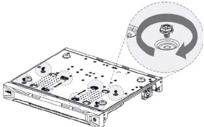
Step 4 Turn the device and put in the other two screws, and then fasten all screws to fix the HDD to the device.
Figure 2-4 Fasten screws
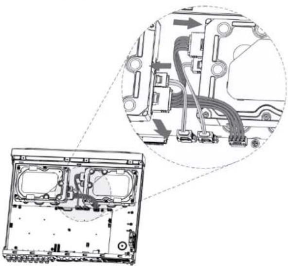
Step 5 Use power cable and data cable to connect the device and HDD.
Figure 2-5 Connect cables
Step 6 Put back the cover and fasten the screws.
Figure 2-6 Put back cover

2.2.2 DH-XVR58xxS-I2/DH-XVR58xxS-4KL-I2/DH-XVR58xxS-4KL-I2-LP/DH-XVR58xxS-I3/DH-XVR58xxS-4KL-I3/DH-XVR58xxS-4KL-I3-LP/DH-XVR78xxS-4K-I2/DH-XVR78xxS-4K-I3/DH-XVR78xxS-4KL-X-LP-V2/DH-XVR88xxS-4KL-I
Step 1 Remove the screws from the chassis.
Figure 2-7 Remove screws

Step 2 Take off the cover of the chassis.
Figure 2-8 Take off cover

Step 3 Remove the screws from the drive bracket to take it off.
Figure 2-9 Take off drive bracket

Step 4 Align the four screw holes on the disk to those on the drive bracket and fix the disk on the bracket.
Figure 2-10 Fix disk

Step 5 Fix other disks on the bracket as needed.
Figure 2-11 Fix other disks

Step 6 Fix the two drive brackets.

This is only needed on models with 8 bays.
Figure 2-12 Fix drive brackets

Step 7 Put the drive brackets back and fix them in the DVR.
Figure 2-13 Put back drive bracket

Step 8 Connect the disks and the DVR with power cable and data cable.

The following figure shows the connection of 4-bay model for example.
Figure 2-14 Connect cables

Step 9 Put the cover back and fasten the screws.
Figure 2-15 Put back cover

2.2.3 DH-XVR54xxL-I2/DH-XVR54xxL-4KL-I2/DH-XVR54xxL-I3/DH-XVR54xxL-4KL-I3/DH-XVR74xxL-4K-I2/DH-XVR74xxL-4K-I3
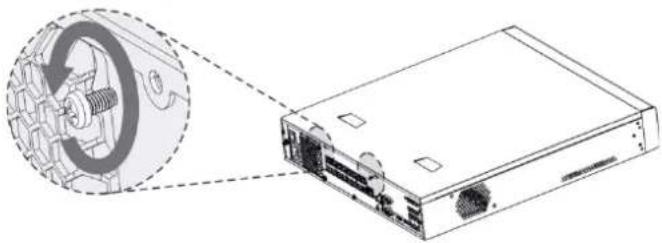
Step 1 Remove the fixing screws from the rear panel.
Figure 2-16 Remove screws
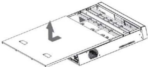
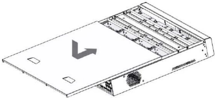
Step 2 Remove the cover along the direction shown in the following arrow.
Figure 2-17 Remove cover
Step 3 Remove the screws on the sides of HDD bracket to take out the bracket. For the way to remove the bracket, see the following figure.
Figure 2-18 Remove bracket
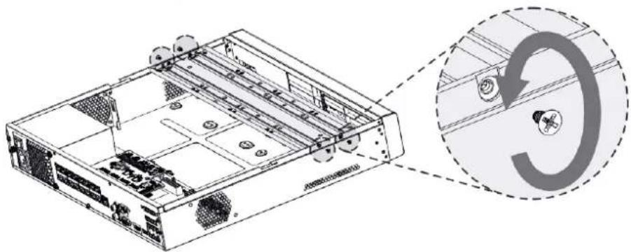
Step 4 Match the four screw holes on the HDD with the four holes on the bracket and then fasten the screws. The HDD is fixed to the bracket.
Figure 2-19 Fix HDD

Step 5 Install the other HDDs.
Figure 2-20 Install other HDDs

Step 6 Place the bracket to the device and then fasten the screws on the sides of the bracket.
Figure 2-21 Fasten screws

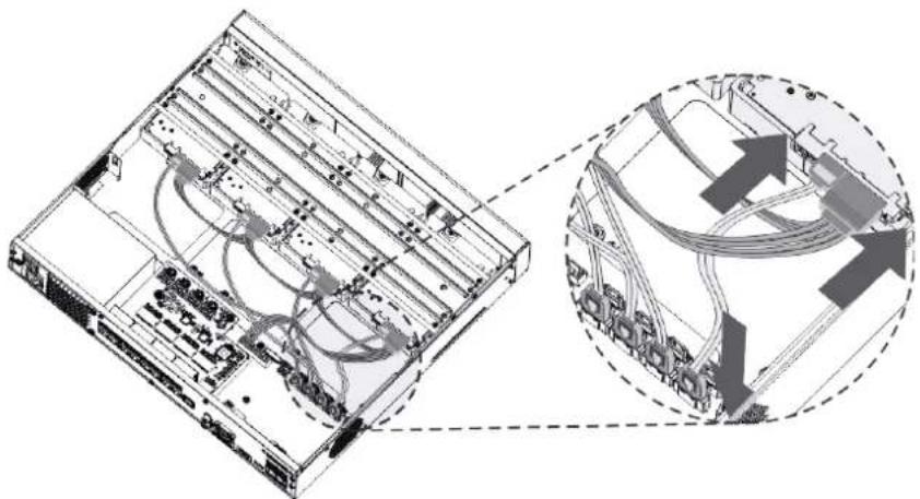
Step 7 Connect the HDD data cable and power cable to the device.
Figure 2-22 Connect cables
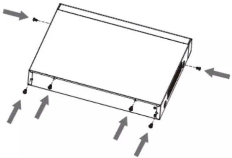
Step 8 Put back the cover and fasten the screws on the rear panel to complete the installation.
Figure 2-23 Put back cover
2.2.4 DH-XVR1Bxx-I/DH-XVR1BxxH-I/DH-XVR41xxC-I/DH-XVR41xxHS-I/DH-XVR51xxH-I/DH-XVR51xxH-I2/DH-XVR51xxH-I3/DH-XVR51xxH-4KL-I2/DH-XVR51xxH-4KL-I3/DH-XVR51xxHE-I2/DH-XVR51xxHE-I3/DH-XVR51xxHE-4KL-I2/DH-XVR51xxHE-4KL-I3/DH-XVR51xxHS-I2/DH-XVR51xxHS-I3/DH-XVR51xxHS-4KL-I2/DH-XVR51xxHS-4KL-I3/DH-XVR71xxH-4K-I2/DH-XVR71xxH-4K-I3/DH-XVR71xxHE-4KL-I/DH-XVR71xxHE-4K-I2/DH-XVR71xxHE-4K-I3
Step 1 Remove the screws on the cover.
Figure 2-24 Remove screws

Step 2 Remove the cover.
Figure 2-25 Remove cover

Step 3 Align the screws of the HDD with the holes on the back of the device and fasten them.
Figure 2-26 Fasten screws

Step 4 Connect the HDD cable and the power cable to the mainboard.
Figure 2-27 Connect cables

Step 5 Put back the cover.
Figure 2-28 Put back cover

Step 6 Fasten the screws.
Figure 2-29 Fasten screws
2.2.5 DH-XVR51xxC-I3/DH-XVR51xxC-4KL-I3
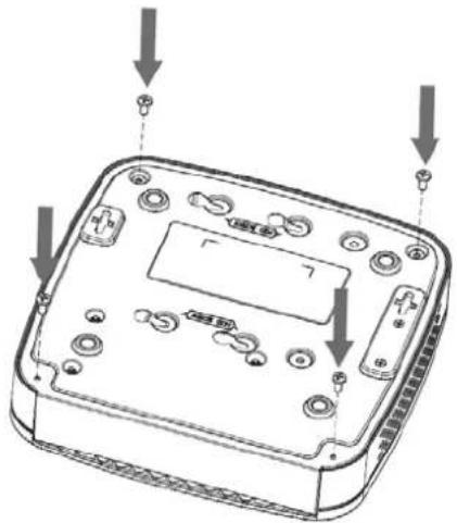
Step 1 Remove the screws.
Figure 2-30 Remove screws

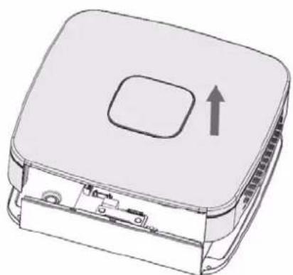
Step 2 Take off the cover.
Figure 2-31 Take off cover
Step 3 Align the screws with the holes on the DVR and fasten them.
Figure 2-32 Install HDD

Step 4 Use the HDD cable and power cable to connect HDD and mainboard.
Figure 2-33 Connect cables

Step 5 Put back the cover.
Figure 2-34 Put back cover

Step 6 Fasten the screws.
Figure 2-35 Fasten screws
3 The Grand Tour
This chapter introduces various components of the Device, remote control and mouse operations.
3.1 Front Panel
3.1.1 DH-XVR51xxH-I
Figure 3-1 Front panel
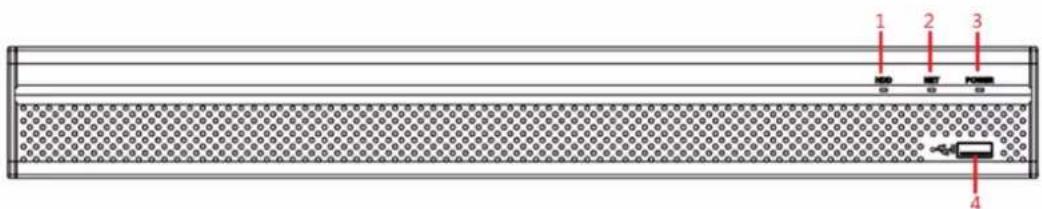
Table 3-1 Front panel description
| No. | Port Name | Function |
| 1 | HDD | Glows blue when HDD status is abnormal. |
| 2 | NET | Glows blue when network status is abnormal. |
| 3 | POWER | Glows blue when the power is connected properly. |
| 4 USB port | Connects to peripheral devices such as USB storage device, keyboard, and mouse. | |
3.1.2 DH-XVR71xxH-4K-I2/DH-XVR71xxH-4K-I3/DH-XVR71xxHE-4K-I2/DH-XVR71xxHE-4K-I3/DH-XVR71xxHE-4KL-I
Figure 3-2 Front panel

Table 3-2 Front panel description
| No. | Port Name | Function |
| 1 USB port | Connects to peripheral devices such as USB storage device, keyboard and mouse. | |
3.1.3 DH-XVR72xxA-4KL-I/DH-XVR72xxAN-4K-I2/DH-XVR72xxA-4K-I2/DH-XVR72xxAN-4K-I3/DH-XVR72xxA-4K-I3
Figure 3-3 Front panel
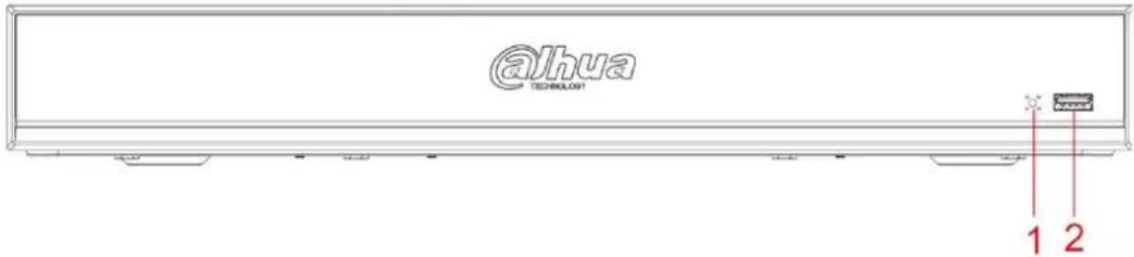
Table 3-3 Front panel description
| No. | Port Name | Function |
| 1 | IR receiver | Receives infrared signal from remote control. |
| 2 USB port | Connects to the external devices such as keyboard, mouse, and USB storage device. | |
3.1.4 DH-XVR82xxA-4K-I/DH-XVR82xxA-4KL-I
Figure 3-4 Front panel

Table 3-4 Front panel description
| No. | Indicator/Port | Function |
| 1 USB port | Connects to peripheral devices such as USB storage device, keyboard, and mouse. | |
| 2 | IR receiver | Receives infrared signal from remote control. |
3.1.5 DH-XVR41xxC-I/DH-XVR41xxHS-I/DH-XVR42xxAN-I/DH-XVR42xxAN-I(V2.0)/DH-XVR51xxH-I2/DH-XVR51xxH-I3/DH-XVR51xxH-4KL-I2/DH-XVR51xxH-4KL-I3/DH-XVR51xxHE-I2/DH-XVR51xxHE-I3/DH-XVR51xxHE-4KL-I2/DH-XVR51xxHE-4KL-I3/DH-XVR51xxHS-I2/DH-XVR51xxHS-I3/DH-XVR51xxHS-4KL-I2/DH-XVR51xxHS-4KL-I3/DH-XVR52xxA-I2/DH-XVR52xxA-I3/DH-XVR52xxA-4KL-I2/DH-XVR52xxA-4KL-I3/DH-XVR52xxAN-I2/DH-XVR52xxAN-I3/DH-XVR52xxAN-4KL-I2/DH-XVR52xxAN-4KL-I3
Figure 3-5 Front panel

Table 3-5 Front panel description
| No. | Port Name | Function |
| 1 | HDD | Glows when HDD status is abnormal. |
| 2 | NET | Glows when network status is abnormal. |
| 3 | POWER | Glows when the power is connected properly. |
| 4 USB port | Connects to peripheral devices such as USB storage device, keyboard, and mouse. | |
3.1.6 DH-XVR78xxS-4K-I2/DH-XVR78xxS-4K-I3/DH-XVR78xxS-4KL-X-LP-V2/DH-XVR88xxS-4KL-I
Figure 3-6 Front panel

Table 3-6 Front panel description
| No. | Port Name | Function |
| 1 | IR receiver | Receives infrared signal from remote control. |
| 2 USB port | Connects to peripheral devices such as USB storage device, keyboard, and mouse. | |
3.1.7 DH-XVR74xxL-4K-I2/DH-XVR74xxL-4K-I3
Figure 3-7 Front panel
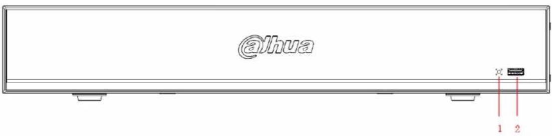
Table 3-7 Front panel description
| No. | Port Name | Function |
| 1 | IR receiver | Receives infrared signal from remote control. |
| 2 USB port | Connects to peripheral devices such as USB storage device, keyboard, and mouse. | |
3.1.8 DH-XVR54xxL-I2/DH-XVR54xxL-4KL-I2/DH-XVR54xxL-I3/DH-XVR54xxL-4KL-I3
Figure 3-8 Front panel
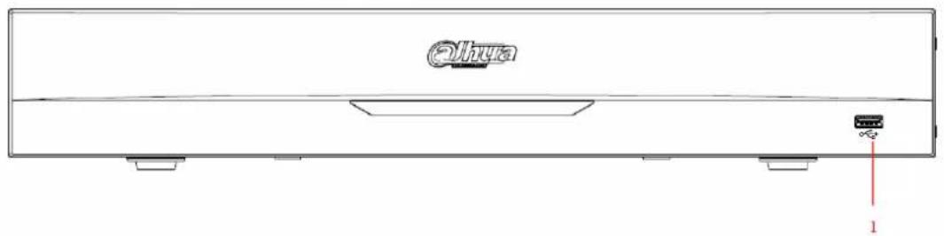
Table 3-8 Front panel description
| No. | Port Name | Function |
| 1 USB port | Connects to peripheral devices such as USB storage device, keyboard, and mouse. | |
3.1.9 DH-XVR58xxS-I2/DH-XVR58xxS-I3/DH-XVR58xxS-4KL-I2/DH-XVR58xxS-4KL-I3/DH-XVR58xxS-4KL-I2-LP/DH-XVR58xxS-4KL-I3-LP
Figure 3-9 Front panel

Table 3-9 Front panel description
| No. | Port Name | Function |
| 1 USB ports | Connect to peripheral devices such as USB storage device, keyboard, and mouse. | |
3.1.10 DH-XVR1Bxx-I/DH-XVR1BxxH-I
Figure 3-10 Front panel

Figure 3-11 Front panel
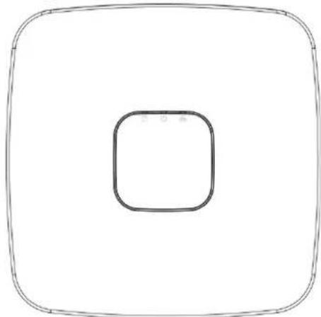
Table 3-10 Front panel description
| Icon | Name | Function |
| HDD status indicator | The indicator is off when the HDD is running normally.The indicator glows blue when the HDD is in malfunction. | |
| Power status indicator | The indicator is off when the power is connected abnormally.The indicator glows blue when the power is connected normally. | |
| Network status indicator | The indicator is off when the network connection is correct.The indicator glows blue when the network connection is abnormal. |
3.2 Rear Panel
3.2.1 DH-XVR51xxH-I/DH-XVR51xxH-I2/DH-XVR51xxH-I3/DH-XVR51xxH-4KL-I2/DH-XVR51xxH-4KL-I3/DH-XVR51xxHE-I2/DH-XVR51xxHE-I3/DH-XVR51xxHE-4KL-I2/DH-XVR51xxHE-4KL-I3/DH-XVR71xxH-4K-I2/DH-XVR71xxH-4K-I3/DH-XVR71xxHE-4K-I2/DH-XVR71xxHE-4K-I3/DH-XVR71xxHE-4KL-I
Figure 3-12 Rear panel
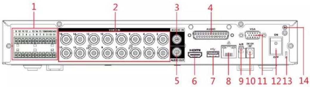
Table 3-11 Rear panel description
| No. | Port Name | Function |
| 1 | Alarm input port 1–16 | Four groups of alarm input ports (Group 1: port 1 to port 4; Group 2: port 5 to port 8; Group 3: port 9 to port 12; Group 4: port 13 to port 16). These ports receive the signal from the external alarm source.There are two types: NO (Normally Open) and NC (Normally Closed).When your alarm input device is using external power, make sure the alarm input device and the Device have the same ground. |
| Alarm output port 1–3 (NO1–NO3; C1–C3) | Three groups of alarm output ports (Group 1: port NO1–C1, Group 2: port NO2–C2, Group 3: port NO3–C3). These ports output alarm signal to the alarm device. Make sure power supply to the external alarm device.NO: Normally open alarm output port.C: Alarm output public end. | |
| 1/= | Ground. | |
| 2 | Video input port | Connects to analog camera to input video signal. |
| 3 Audio input port | Receives audio signal output from the devices such as microphone.It corresponds to video input port 1. | |
| 4 DB25 | port | Connects to the audio splitter taken from the package to convert to audio input port which receives the audio signal from devices such as microphone. It corresponds to video input ports 2–16. |
| 5 | Audio output port | Outputs audio signal to the devices such as the sound box. |
| 6 HDMI | port | High definition audio and video signal output port.The port outputs the uncompressed high definition video and multi-channel audio data to the connected display with HDMI port. |
| 7 USB | port | Connects to external devices such as USB storage device, keyboard and mouse. |
| 8 | Network port | Connects to Ethernet port. |
| 9 | RS-485 communication port | Connects to the control devices such as speed dome PTZ. RS-485_A port is connected by the cable A and RS-485_B is connected to the cable B. |
| 10 | Power input port | Inputs 12 VDC power. |
| 11 | VGA port | Outputs analog video data to the connected display with VGA port. |
| 12 | Power button | Turns on/off the DVR. |
| 13 | Power cable fastener | Use a cable tie to secure the power cable on the DVR to prevent loss. |
| 14 | Ground terminal. | |
3.2.2 DH-XVR41xxC-I/DH-XVR41xxHS-I/DH-XVR51xxHS-I2/DH-XVR51xxHS-I3/DH-XVR51xxHS-4KL-I2/DH-XVR51xxHS-4KL-I3
Figure 3-13 Rear panel

Table 3-12 Rear panel description
| No. | Port Name | Function |
| 1 | Video input port | Connects to analog camera to input video signal. |
| 2 | Audio input port | Receives audio signal output from the devices such as microphone. |
| 3 | Audio output port | Outputs audio signal to the devices such as the sound box. |
| 4 HDMI | port | High definition audio and video signal output port.The port outputs the uncompressed high definition video and multi-channel audio data to the connected display with HDMI port. |
| 5 | Network port | Connects to Ethernet port. |
| 6 | RS-485 communication port | Connects to the control devices such as speed dome PTZ. RS-485_A port is connected by the cable A and RS-485_B is connected to the cable B. |
| 7 | VGA port | Outputs analog video data to the connected display with VGA port. |
| 8 USB port | Connects to external devices such as USB storage device, keyboard and mouse. | |
| 9 | Power input port | Inputs 12 VDC power. |
| 10 | Power cable fastener | Use clamp to secure the power cable on the DVR in case there is any loss. |
| 11 | Ground terminal. | |
3.2.3 DH-XVR52xxA-I2/DH-XVR52xxA-I3/DH-XVR52xxA-4KL-I2/DH-XVR52xxA-4KL-I3/DHXVR42xxAN-I/DH-XVR42xxAN-I(V2.0)/DH-XVR52xxAN-I2/DH-XVR52xxAN-I3/DH-XVR52xxAN-4KL-I2/DH-XVR52xxAN-4KL-I3/DH-XVR72xxA-4K-I2/DH-XVR72xxA-4K-I3/DH-XVR72xxA-4KL-I/DH-XVR72xxAN-4K-I2/DH-XVR72xxAN-4K-I3
Figure 3-14 Rear panel

Table 3-13 Rear panel description
| No. | Port Name | Function |
| 1 | Ground terminal. | |
| 2 | Alarm input port 1-16 | Four groups of alarm input ports (Group 1: port 1 to port 4; Group 2: port 5 to port 8; Group 3: port 9 to port 12; Group 4: port 13 to port 16). These ports receive the signal from the external alarm source.There are two types: NO (Normally Open) and NC (Normally Closed).When your alarm input device is using external power, make sure the alarm input device and the DVR connect to the same ground. |
| Alarm output port 1-3 (NO1-NO3; C1-C3) | Three groups of alarm output ports. (Group 1: port NO1-C1, Group 2: port NO2-C2, Group 3: port NO3-C3). These ports output alarm signal to the alarm device. Make sure power supply to the external alarm device.NO: Normally open alarm output port.C: Alarm output public end. | |
| 1/2 | Ground. | |
| 3 | Video input port | Connects to analog camera to input video signal. |
| 4 | Audio input port | Receives audio signal output from the devices such as microphone. |
| 5 | Audio output port | Outputs audio signal to the devices such as the sound box. |
| 6 HDMI | port | High definition audio and video signal output port.The port outputs the uncompressed high definition video and multi-channel audio data to the connected display with HDMI port. |
| 7 USB port | Connects to the external devices such as keyboard, mouse, and USB storage device. | |
| 8 | Network port | Connects to Ethernet port. |
| 9 | RS-485 communication port | Connects to the control devices such as speed dome PTZ. RS-485_A port is connected by the cable A and RS-485_B is connected to the cable B. |
| 10 | Power input port | Inputs 12 VDC power. |
| 11 | VGA port | Outputs analog video data to the connected display with VGA port. |
| 12 | Power button | Turns on/off the DVR. |
| 13 | Power cable fastener | Use clamp to secure the power cable on the DVR in case there is any loss. |
3.2.4 DH-XVR82xxA-4K-I/DH-XVR82xxA-4KL-I
Figure 3-15 Rear panel

Table 3-14 Rear panel description
| No. | Port Name | Function |
| 1 | Video input port | Connects to analog camera to input video signal. |
| 2 | Audio output port | Outputs audio signal to the devices such as the sound box. |
| 3 | MIC IN | Two-way talk input port which receives analog audio signal output from the devices such as microphone and pickup. |
| 4 | Audio input port | Receives audio signal output from the devices such as microphone. |
| 5 | RS-232 debug COM | The port is used for general COM debug to configure IP address or transfer transparent COM data. |
| 6 | Alarm input port1–16 | 4 groups of alarm input ports (Group 1: port 1 to port 4; Group 2: port 5 to port 8; Group 3: port 9 to port 12; Group 4: port 13 to port 16). These ports receive the signal from the external alarm source.There are two types: NO (normal open) and NC (normal close).When your alarm input device is using external power, make sure the input device and the DVR connect to the same ground. |
| ⊕ | Ground terminal. | |
| 7 | VGA port | Outputs analog video data to the connected display with VGA port. |
| 8 | Network port | Connects to Ethernet port. |
| 9 HDMI port | High definition audio and video signal output port.The port outputs the uncompressed high definition video and multi-channel audio data to the connected display with HDMI port. | |
| 10 USB port | Connects to the external devices such as keyboard, mouse, and USB storage device. | |
| 11 | Power input port | Inputs power. |
| 12 | Alarm output port 1–5 (NO1–NO5; C1–C5; NC5) | 5 groups of alarm output ports (Group 1: port NO1–C1, Group 2: port NO2–C2, Group 3: port NO3–C3, Group 4: port NO4–C4, Group 5: port NO5, C5, NC5). These ports output alarm signal to the alarm device. Make sure power supply to the external alarm device.NO: Normal open alarm output port.C: Alarm output public end.NC: Normal close alarm output port. |
| 13 | Power button | Turns on/off the DVR. |
| 14 | ± | Ground. |
3.2.5 DH-XVR58xxS-I2/DH-XVR58xxS-4KL-I2/DH-XVR58xxS-I3/DH-XVR58xxS-4KL-I3/DH-XVR78xxS-4K-I2/DH-XVR78xxS-4K-I3/DH-XVR88xxS-4KL-I
Figure 3-16 Rear panel

Table 3-15 Rear panel description
| No. | Port Name | Function |
| 1 GND | Ground. | |
| 2 | Power input port | Inputs power. |
| 3 | Power button | Turns on/off the Device. |
| 4 | Audio input port | Receives the analog audio signal output from the devices such as microphone. |
| 5 | Audio input port (MIC IN) | Two-way talk input port which receives the analog audio signal output from the devices such as microphone, pickup. |
| 6 | Audio output port (MIC OUT) | Two-way talk output port which outputs the analog audio signal to the devices such as the sound box. |
| 7 | Audio output port | Outputs the analog audio signal to the devices such as the sound box. |
| 8 | Video output port | Connect to video output devices such as TV. |
| 9 | Alarm input port 1-16 | Four groups of alarm output ports (Group 1: port 1 to port 4; Group 2: port 5 to port 8; Group 3: port 9 to port 12; Group 4: port 13 to port 16). These ports receive the signal from the external alarm source. There are two types; NO (Normally Open) and NC (Normally Closed).When your alarm input device is using external power, make sure the device and the NVR have the same ground. |
| Alarm output port 1-5 (NO1-NO5; C1-C5; NC5) | Five groups of alarm output ports. (Group 1: port NO1-C1, Group 2: port NO2-C2, Group 3: port NO3-C3, Group 4: port NO4-C4, Group 5: port NO5, C5, NC5). These ports output alarm signal to the alarm device. Make sure power supply to the external alarm device.NO: Normally open alarm output port.C: Alarm output public end.NC: Normally closed alarm output port. | |
| RS-485 communication port | You can connect to the control devices such as speed dome PTZ.RS-485_A port is connected by the cable A and RS-485_B is connected to the cable B. | |
| Four-wire full-duplex RS-485 port (T+, T-, R+, R-) | Four-wire full-duplex 485 port. T+ and T- is the output wire; R+ and R- is the input wire. | |
| Control power output (CTRL 12V) | Controls 12 VDC power output. It is to control the on-off alarm relay output. | |
| 12V power output port | Provides power to external devices such as camera and alarm device. Note the supplying power shall be below 1A. | |
| ± | Ground. | |
| 10 | Video input port | Connect to analog camera to input video signal. |
| 11 | Network port | Connects to Ethernet port. |
| 12 VGA | video output | Outputs analog video signal. It can connect to the monitor to view analog video. |
| 13 | RS-232 debug COM | It is for general COM debug to configure IP address or transfer transparent COM data. |
| 14 HDMI port | High definition audio and video signal output port. It outputs the same video source as VGA. It supports 4K resolution output and supports mouse operation and control.Note when the HDMI output resolution is 4K, the VGA output stops. | |
| 15 USB port | Connects to the external devices such as keyboard, mouse, and USB storage device. | |
| 16 | eSATA port | External SATA port which connects to the device with SATA port.Perform the jumper configuration when connecting HDD. |
3.2.6 DH-XVR58xxS-4KL-I2-LP/DH-XVR58xxS-4KL-I3-LP/DH-
XVR78xxS-4KL-X-LP-V2
Figure 3-17 Rear panel

Table 3-16 Rear panel description
| No. | Port Name | Function |
| 1 Audio output port | Outputs the analog audio signal to the devices such as the sound box. | |
| 2 | Video output port | Connect to video output devices such as TV. |
| 3 | Audio input port (MIC IN) | Two-way talk input port which receives the analog audio signal output from the devices such as microphone, pickup. |
| 4 | Audio output port (MIC OUT) | Two-way talk output port which outputs the analog audio signal to the devices such as the sound box. |
| 5 | Audio input port | Receives the analog audio signal output from the devices such as microphone. |
| 6 | Alarm input port 1-16 | Four groups of alarm output ports (Group 1: port 1 to port 4; Group 2: port 5 to port 8; Group 3: port 9 to port 12; Group 4: port 13 to port 16). These ports receive the signal from the external alarm source. There are two types; NO (Normally Open) and NC (Normally Closed).When your alarm input device is using external power, make sure that the device and the NVR have the same ground. |
| Alarm output port 1-5 (NO1-NO5; C1-C5; NC5) | Five groups of alarm output ports. (Group 1: port NO1-C1,Group 2: port NO2-C2,Group 3: port NO3-C3, Group 4: port NO4-C4, Group 5: port NO5, C5, NC5). These ports output alarm signal to the alarm device. Make sure that power supply to the external alarm device.NO: Normally open alarm output port.C: Alarm output public end.NC: Normally closed alarm output port. | |
| RS-485 communication port | You can connect to the control devices such as speed dome PTZ.RS-485_A port is connected by the cable A and RS-485_B is connected to the cable B. | |
| Four-wire full-duplex RS-485 port (T+, T-, R+, R-) | Four-wire full-duplex 485 port. T+ and T- is the output wire; R+ and R- is the input wire. | |
| Control power output (CTRL 12V) | Controls the 6th channel power output for alarm.Turns off power output when there is alarm output.Turns on power output when the alarm is cleared. | |
| 12V power output port | Provides power to external devices such as camera and alarm device. Note the supplying power shall be below 1A. | |
| G Ground. | ||
| 7 | RS-232 debug COM | It is for general COM debug to configure IP address or transfer transparent COM data. |
| 8 VGA video output | Outputs analog video signal. It can connect to the monitor to view analog video. | |
| 9 | Power button | Turns on/off the Device. |
| 10 | Power input port | Inputs power. |
| 11 | Loop out | Outputs the video signal of the corresponding video input port. |
| 12 | Video input port | Connect to analog camera to input video signal. |
| 13 | Network port | Connects to Ethernet port. |
| 14 USB port | Connects to the external devices such as keyboard, mouse, and USB storage device. | |
| 15 | eSATA port | External SATA port which connects to the device with SATA port. Perform the jumper configuration when connecting HDD. |
| 16 HDMI port | High definition audio and video signal output port. It outputs the same video source as VGA. It supports 4K resolution output and supports mouse operation and control.Note when the HDMI output resolution is 4K, the VGA output stops. | |
| 17 | GND | Ground. |
3.2.7 DH-XVR54xxL-I2/DH-XVR54xxL-4KL-I2/DH-XVR54xxL-I3/DH-
XVR54xxL-4KL-I3/DH-XVR74xxL-4K-I2/DH-XVR74xxL-4K-I3
Figure 3-18 Rear panel (1)

Figure 3-19 Rear panel (2)
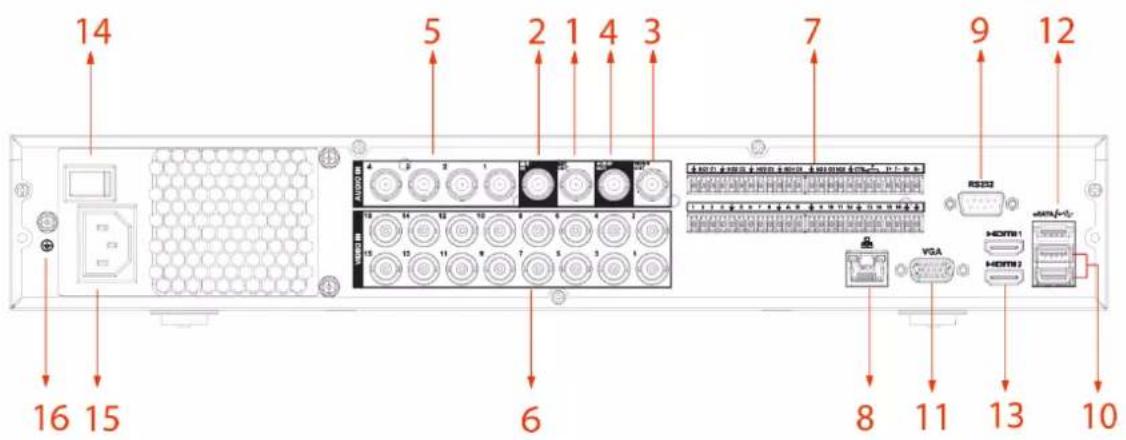
Figure 3-20 Rear panel (3)

Table 3-17 Rear panel description
| No. | Port Name | Function |
| 1 | Audio output port (MIC OUT) | Two-way talk output port which outputs the analog audio signal to the devices such as the sound box. |
| 2 | Audio input port (MIC IN) | Two-way talk input port which receives the analog audio signal output from the devices such as microphone, pickup. |
| 3 Video | output port | Connect to video output devices such as TV. |
| 4 | Audio output port | Outputs the analog audio signal to the devices such as the sound box. |
| 5 | Audio input port | Receives the analog audio signal output from the devices such as microphone. |
| 6 | Video input port | Connect to analog camera to input video signal. |
| 7 | Alarm input port 1-16 | Four groups of alarm output ports (Group 1: port 1 to port 4; Group 2: port 5 to port 8; Group 3: port 9 to port 12; Group 4: port 13 to port 16). These ports receive the signal from the external alarm source. There are two types; NO (Normally Open) and NC (Normally Closed).When your alarm input device is using external power, make sure the device and the NVR have the same ground. |
| Alarm output port 1-5 (NO1-NO5; C1-C5; NC5) | Five groups of alarm output ports. (Group 1: port NO1-C1, Group 2: port NO2-C2, Group 3: port NO3-C3, Group 4: port NO4-C4, Group 5: port NO5, C5, NC5). These ports output alarm signal to the alarm device. Make sure power supply to the external alarm device.NO: Normally open alarm output port.C: Alarm output public end.NC: Normally closed alarm output port. | |
| RS-485 communication port | You can connect to the control devices such as speed dome PTZ.RS-485_A port is connected by the cable A and RS-485_B is connected to the cable B. | |
| Four-wire full-duplex RS-485 port (T+, T-, R+, R-) | Four-wire full-duplex 485 port. T+ and T- is the output wire; R+ and R- is the input wire. | |
| Control power output (CTRL 12V) | Controls 12 VDC power output. It is to control the on-off alarm relay output. | |
| 12V power output port | Provides power to external devices such as camera and alarm device. Note the supplying power shall be below 1A. | |
| ± | Ground. | |
| 8 | Network port | Connects to Ethernet port. |
| 9 | RS-232 debug COM | It is for general COM debug to configure IP address or transfer transparent COM data. |
| 10 USB | port | Connects to the external devices such as keyboard, mouse, and USB storage device. |
| 11 VGA | video output | Outputs analog video signal. It can connect to the monitor to view analog video. |
| 12 eSATA | port | External SATA port which connects to the device with SATA port.Perform the jumper configuration when connecting HDD. |
| 13 HDMI | port | High definition audio and video signal output port. It outputs the same video source as VGA. It supports 4K resolution output and supports mouse operation and control.Note when the HDMI output resolution is 4K, the VGA output stops. |
| 14 | Power switch | Turns on/off the Device. |
| 15 | Power input port | Inputs power. |
| 16 | GND | Ground. |
3.2.8 DH-XVR1Bxx-I/DH-XVR1BxxH-I
Figure 3-21 Rear panel
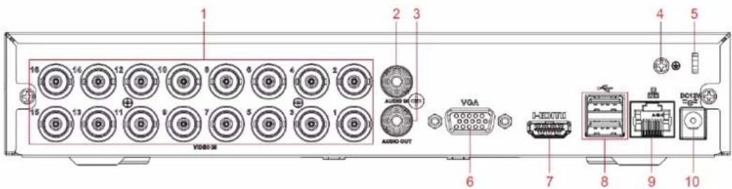
Table 3-18 Rear panel description
| No. | Port Name | Function |
| 1 | Video input port | Connect to analog camera to input video signal. |
| 2 | Audio input port | Receives the analog audio signal output from the devices such as microphone. |
| 3 Audio output port | Outputs the analog audio signal to the devices such as the sound box. | |
| 4 GND | Ground. | |
| 5 | Power cable fastener | Use clamp to secure the power cable on the DVR in case there is any loss. |
| 6 VGA video output | Outputs analog video signal. It can connect to the monitor to view analog video. | |
| 7 HDMI port | High definition audio and video signal output port. It outputs the same video source as VGA. It supports 4K resolution output and supports mouse operation and control.Note when the HDMI output resolution is 4K, the VGA output stops. | |
| 8 USB port | Connects to the external devices such as keyboard, mouse, and USB storage device. | |
| 9 | Network port | Connects to Ethernet port. |
| 10 | Power input port | Inputs power. |
3.2.9 DH-XVR51xxC-I3/DH-XVR51xxC-4KL-I3
Figure 3-22 Rear panel

Table 3-19 Rear panel description
| No. | Port Name | Function |
| 1 | Video input port | Connects to analog camera to input video signal. |
| 2 USB port | Connects to external devices such as USB storage device, keyboard and mouse. | |
| 3 | VGA port | Outputs analog video data to the connected display with VGA port. |
| 4 HDMI | port | High definition audio and video signal output port.The port outputs the uncompressed high definition video and multi-channel audio data to the connected display with HDMI port. |
| 5 | Network port | Connects to Ethernet port. |
| 6 | Power input port | Inputs 12 VDC power. |
| 7 | Ground terminal. | |
3.3 Remote Control Operations

Note the remote control is not our standard accessory and might not be included in the accessory bag. It is supplied dependent on the model you purchased.
Figure 3-23 Remote control

Table 3-20 Remote control description
| No. | Name | Function |
| 1 | Power button | Press this button to boot up or shut down the device. |
| 2 Address | Press this button to input device serial number, so that you can control the Device. | |
| 3 | Forward | Multi-step forward speed and normal speed playback. |
| 4 | Slow motion | Multi-step slow motion speed or normal playback. |
| 5 | Next record | In playback state, press this button to play back the next video. |
| 6 | Previous record | In playback state, press this button to play back the previous video. |
| 7 Play/Pause | In normal playback state, press this button to pause playback.In pause state, press this button to resume to normal playback.In live view window page, press this button to enter video search menu. | |
| 8 Reverse/pause | In the reverse playback state, press this button to pause reverse playback. | |
| In the reverse playback pause state, press this button to resume to playback reversing state. | ||
| 9 Esc. | Go back to previous menu or cancel current operation (close front page or control). | |
- FOREWORD
- GENERAL
- SAFETY INSTRUCTIONS
- PRIVACY PROTECTION NOTICE
- ABOUT THE MANUAL
- IMPORTANT SAFEGUARDS AND WARNINGS
- OPERATION REQUIREMENTS
- ELECTRICAL SAFETY
- TABLE OF CONTENTS
- FOREWORD....II
- IMPORTANT SAFEGUARDS AND WARNINGS......V
- 1 INTRODUCTION.... 1
- 2 GETTING STARTED.... 3
- 3 THE GRAND TOUR 16
- 3.2 REAR PANEL 22
- 3.3 REMOTE CONTROL OPERATIONS 34
- 3.4 MOUSE OPERATIONS 36
- 4 CONNECTION.... 38
- 4.3 CONNECTING TO ALARM INPUT AND OUTPUT....40
- 5 LOCAL CONFIGURATIONS 43
- USER'S MANUAL
- 6 WEB OPERATIONS 350
- 7 FAQ 354
- 1 INTRODUCTION
- 1.1 OVERVIEW
- 1.2 FUNCTIONS
- AI FUNCTION
- REAL-TIME SURVEILLANCE
- IOT MANAGEMENT
- SENSOR INTEGRATION
- STORAGE MANAGEMENT
- COMPRESSION FORMAT
- BACKUP FUNCTION
- RECORD & PLAYBACK
- NETWORK OPERATION
- ALARM ACTIVATION
- COMMUNICATION PORT
- PTZ CONTROL
- INTELLIGENT OPERATION
- UPNP (UNIVERSAL PLUG AND PLAY)
- CAMERA SELF-ADAPTIVE
- 2 GETTING STARTED
- 2.1 CHECKING THE COMPONENTS
- 2.2 INSTALLING HDD
- 2.2.2 DH-XVR58XXS-I2/DH-XVR58XXS-4KL-I2/DH-XVR58XXS-4KL-I2-LP/DH-XVR58XXS-I3/DH-XVR58XXS-4KL-I3/DH-XVR58XXS-4KL-I3-LP/DH-XVR78XXS-4K-I2/DH-XVR78XXS-4K-I3/DH-XVR78XXS-4KL-X-LP-V2/DH-XVR88XXS-4KL-I
- 2.2.3 DH-XVR54XXL-I2/DH-XVR54XXL-4KL-I2/DH-XVR54XXL-I3/DH-XVR54XXL-4KL-I3/DH-XVR74XXL-4K-I2/DH-XVR74XXL-4K-I3
- 2.2.5 DH-XVR51XXC-I3/DH-XVR51XXC-4KL-I3
- 3 THE GRAND TOUR
- 3.1 FRONT PANEL
- 3.1.1 DH-XVR51XXH-I
- 3.1.2 DH-XVR71XXH-4K-I2/DH-XVR71XXH-4K-I3/DH-XVR71XXHE-4K-I2/DH-XVR71XXHE-4K-I3/DH-XVR71XXHE-4KL-I
- 3.1.3 DH-XVR72XXA-4KL-I/DH-XVR72XXAN-4K-I2/DH-XVR72XXA-4K-I2/DH-XVR72XXAN-4K-I3/DH-XVR72XXA-4K-I3
- 3.1.4 DH-XVR82XXA-4K-I/DH-XVR82XXA-4KL-I
- 3.1.6 DH-XVR78XXS-4K-I2/DH-XVR78XXS-4K-I3/DH-XVR78XXS-4KL-X-LP-V2/DH-XVR88XXS-4KL-I
- 3.1.7 DH-XVR74XXL-4K-I2/DH-XVR74XXL-4K-I3
- 3.1.8 DH-XVR54XXL-I2/DH-XVR54XXL-4KL-I2/DH-XVR54XXL-I3/DH-XVR54XXL-4KL-I3
- 3.1.9 DH-XVR58XXS-I2/DH-XVR58XXS-I3/DH-XVR58XXS-4KL-I2/DH-XVR58XXS-4KL-I3/DH-XVR58XXS-4KL-I2-LP/DH-XVR58XXS-4KL-I3-LP
- 3.1.10 DH-XVR1BXX-I/DH-XVR1BXXH-I
- 3.2 REAR PANEL
- 3.2.2 DH-XVR41XXC-I/DH-XVR41XXHS-I/DH-XVR51XXHS-I2/DH-XVR51XXHS-I3/DH-XVR51XXHS-4KL-I2/DH-XVR51XXHS-4KL-I3
- 3.2.3 DH-XVR52XXA-I2/DH-XVR52XXA-I3/DH-XVR52XXA-4KL-I2/DH-XVR52XXA-4KL-I3/DHXVR42XXAN-I/DH-XVR42XXAN-I(V2.0)/DH-XVR52XXAN-I2/DH-XVR52XXAN-I3/DH-XVR52XXAN-4KL-I2/DH-XVR52XXAN-4KL-I3/DH-XVR72XXA-4K-I2/DH-XVR72XXA-4K-I3/DH-XVR72XXA-4KL-I/DH-XVR72XXAN-4K-I2/DH-XVR72XXAN-4K-I3
- 3.2.4 DH-XVR82XXA-4K-I/DH-XVR82XXA-4KL-I
- 3.2.5 DH-XVR58XXS-I2/DH-XVR58XXS-4KL-I2/DH-XVR58XXS-I3/DH-XVR58XXS-4KL-I3/DH-XVR78XXS-4K-I2/DH-XVR78XXS-4K-I3/DH-XVR88XXS-4KL-I
- 3.2.6 DH-XVR58XXS-4KL-I2-LP/DH-XVR58XXS-4KL-I3-LP/DH
- XVR78XXS-4KL-X-LP-V2
- 3.2.7 DH-XVR54XXL-I2/DH-XVR54XXL-4KL-I2/DH-XVR54XXL-I3/DH
- XVR54XXL-4KL-I3/DH-XVR74XXL-4K-I2/DH-XVR74XXL-4K-I3
- 3.2.8 DH-XVR1BXX-I/DH-XVR1BXXH-I
- 3.2.9 DH-XVR51XXC-I3/DH-XVR51XXC-4KL-I3
- 3.3 REMOTE CONTROL OPERATIONS
Brand : Dahua Technology
Model : XVR5108H-4KL-I2
Category : Digital Video Recorder