
DAV-6470 - Temperature regulator DAVIS - Free user manual and instructions
Find the device manual for free DAV-6470 DAVIS in PDF.


| Product Type | Temperature Regulator |
| Brand | DAVIS |
| Model | DAV-6470 |
| Dimensions (H x W x D) | 120 x 80 x 30 mm |
| Weight | 150 g |
| Power Supply | 230V AC, 50Hz |
| Display Type | Backlit LCD |
| Temperature Range | 5°C to 35°C |
| Accuracy | ±0.5°C |
| Control Type | On/Off (mechanical relay) |
| Operating Modes | Heat, Cool, Auto, Frost Protection |
| Key Features | Set temperature, hysteresis, child lock, low battery indicator |
| Installation | Wall-mounted (standard box) |
| Material | Flame-retardant ABS plastic |
| Certifications | CE, RoHS, WEEE |
| Warranty | 2 years |
| Includes | Mounting screws, user manual |
| Maintenance | Clean with a soft, dry cloth. Do not use liquids. |
| Safety | Disconnect power before installation. Ensure correct wiring. |
Frequently Asked Questions - DAV-6470 DAVIS
User questions about DAV-6470 DAVIS
0 question about this device. Answer the ones you know or ask your own.
Ask a new question about this device
Download the instructions for your Temperature regulator in PDF format for free! Find your manual DAV-6470 - DAVIS and take your electronic device back in hand. On this page are published all the documents necessary for the use of your device. DAV-6470 by DAVIS.
USER MANUAL DAV-6470 DAVIS
Soil Moisture Sensor & Multi-Purpose Temperature Probe Installation Instructions
For Wireless Leaf & Soil Moisture/Temperature Stations
The WATERMARK Soil Moisture Sensor and the Multi-Purpose Temperature Probe are for use with the Vantage Pro2 Wireless Leaf & Soil Moisture/Temperature Station, #6345. Please refer to your Wireless Leaf & Soil Moisture/Temperature Station manual for more information on how to install and use the sensors.
Installation Procedures
Connecting the Sensors
- To extend the sensor cables, see “Extending Sensor Cables” on page 4.
- To use a temperature probe for temperature compensation of a soil moisture sensor, install the sensor pair in corresponding connectors: 1 & 1, 2 & 2, 3 & 3, and 4 & 4.
- If no soil temperature probe is used, the station will use a default temp of 75°F (24°C) to compensate the soil moisture readings.
- If you are installing a temperature probe that is not providing temperature compensation for a soil moisture reading, do not use a connector that matches to any installed soil moisture sensor.
- If a soil moister / temperature sensor pair do not use matching connectors, the soil moisture reading can be off as much as 1% for every 1°F(0.5°C) error in the soil temperature.
-
Run the sensor cables up through the grommets on the bottom of the station housing.
-
Connect soil moisture probes to the SOIL connectors.
-
Connect the temperature probes to the TEMP connectors.
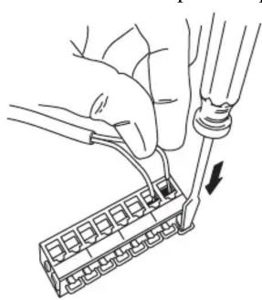
Connecting Sensor Cable to Terminal Block

Sensor Cables Enter Station Housing Through Grommets
- Secure all sensor cables through the provided cable clamps and then secure the mounts by driving a screw through the clamp into the cable clamp mounts located above the grommets.
Before "Planting" the Sensors
If you can, soak soil moisture sensors overnight in water before installing them.
- Always “plant” a wet soil moisture sensor.
- If time permits, wet the soil moisture sensor for 30 minutes in the morning and let dry until evening, wet for 30 minutes and let dry overnight, wet again for 30 minutes the next morning and let dry again until evening. Soak over the next night and install wet. This will improve sensor response during the first few irrigations or waterings.
"Planting" the Sensors
-
Make sensor access holes to the depth required with a 7/8" diameter rod.
-
Make a hole for the soil moisture sensor and a separate adjacent hole for the temperature probe.
- For very coarse or gravely soils, an oversize hole of 1" to 1 1/4" may be needed to prevent abrasion damage to the soil moisture sensor membrane. In this case, you will need to "grout in" the sensor with a slurry made from the sample soil to get a snug fit in the soil.
- Always install sensors in the active root system of the crop with a snug fit in the soil.
CAUTION: In gravelly soils and with deeper sensors, you must use extra caution to install the soil moisture sensor without damaging the membrane.
- Lack of a snug fit is the biggest problem in obtaining good soil moisture sensor readings.
- The ideal method of making the access hole is to have a stepped tool. This makes an oversize hole for the upper portion and an exact sized hole at the bottom where the sensor is located.

Stepped Sensor Installation Tool
- Fill the hole with water and push the sensor down into the hole so it bottoms out.
- A length of 1/2" Class 315 PVC pipe (pipe inside diameter = 0.716", 18.18mm) fits snugly over the sensor collar and can be used to push the sensor. A good snug fit in the soil is important.

- You can solvent weld the 1/2" Class 315 PVC pipe to the sensor collar for easier installation and removal. Use a PVC/ABS cement (IPS Weld-on #794 or equivalent).
- Carefully backfill the access hole with soil to eliminate any air pockets which could allow water to channel down to the sensor.
- If you are using temperature sensors, install the temperature sensor next to the soil moisture sensor.
Note: Soil moisture sensors will provide better accuracy after one or two irrigation cycles, during which time they “break-in” and acclimate to the soil conditions.
"Planting" Sensors in Turf or Lawns
- Cut a slight “V” shaped trench about 5” wide at the top, and about 6” deep into the turf, and about 6” long.
- Lift out the turf plug piece you just cut.
- Press the sensors into the soil at about a 45 degree angle into the side of the trench to set the sensors about 3"-5" below the soil surface. Make sure they are set snugly in the soil.
- Replace the plug removed from the trench and compact it back into place. It will repair itself in short order.
-
Run the wires to the Soil Moisture Station and connect them as described in “Connecting the Sensors” on page 1.
-
If you withhold irrigation for several days and allow the soil to dry down a bit, you should see the soil moisture readings start to creep upward.
- Usually, you will not need to water turf until the soil moisture reading is around 25-40 centibars at the recommended 3"-5" depth.
Extending Sensor Cables
The soil moisture sensor and the temperature probe both come with a 15' (4.6 m) cable.
- If additional wiring is required, up to 1000' (300 m) of additional wire can be spliced onto the sensor wire.
- The additional wire must be fully waterproof.
- We recommend using #18 gauge wire with UF insulation, and using a 3M Scotchpak or Duraseal heat shrink splice connector.
Note: Avoid long wire runs near power cables. The transient currents can affect the small current used to read the sensors.
Removing the Sensors
- When removing sensors prior to harvest in annual crops, it's a good idea to do this just after the last irrigation when the soil is moist.
- Do not pull the sensor out by the wires. You may have to dig out, at least partially, any sensors more than 12" deep or any sensors in dry soil. Careful removal prevents sensor and sensor membrane damage.
- When sensors are removed for winter storage, rinse the sensors in water to clean them, let the sensors dry, then store the sensors in a clean, dry location.
Contacting Davis Instruments
(510) 732-7814 Technical Support, Monday – Friday, 7:00 a.m. – 5:30 p.m. Pacific Time. (510) 670-0589 Fax to Customer Service or Tech Support. support@davisnet.com E-mail to Technical Support. info@davisnet.com General e-mail. www.davisnet.com Copies of User Manuals, Spec Sheets, and Application Notes are available on the “Support” page. Watch for FAQs and other updates. Subscribe to the e-newsletter.
Product Numbers: 6440, 6470
Davis Instruments Part Number: 07395.158C
Soil Moisture Sensor & Multi-Purpose Temperature Probe Installation Instructions Rev. C Manual (2/25/05)
This product complies with the essential protection requirements of the EC EMC Directive 89/336.

3465 Diablo Avenue, Hayward, CA 94545-2778
510-732-9229 · Fax: 510-732-9188
E-mail: info@davisnet.com • www.davisnet.com
- SOIL MOISTURE SENSOR & MULTI-PURPOSE TEMPERATURE PROBE INSTALLATION INSTRUCTIONS
- FOR WIRELESS LEAF & SOIL MOISTURE/TEMPERATURE STATIONS
- INSTALLATION PROCEDURES
- BEFORE "PLANTING" THE SENSORS
- PLANTING" THE SENSORS
- PLANTING" SENSORS IN TURF OR LAWNS
- EXTENDING SENSOR CABLES
- REMOVING THE SENSORS
- CONTACTING DAVIS INSTRUMENTS
Brand : DAVIS
Model : DAV-6470
Category : Temperature regulator