
ARO 120 SX (2020) - Snowmobile Timbersled - Free user manual and instructions
Find the device manual for free ARO 120 SX (2020) Timbersled in PDF.


| Product Type | Snow bike conversion kit |
| Brand | Timbersled |
| Model | ARO 120 SX (2020) |
| Estimated Dry Weight - Front | 16.5 lbs (7.4 kg) |
| Estimated Dry Weight - Rear | 120 lbs (54.43 kg) |
| Overall Length (pivot to bumper) | 63.0 in (160.0 cm) |
| Disc Brake Type | Wilwood Hydraulic Dual Piston |
| Track Drive Sprocket | 6 tooth / 2.86 pitch |
| Drive Shaft Sprocket | 17 tooth - 15t spline |
| Upper Chain Case Sprocket | 18 tooth - 15t spline |
| Lower Chain Case Sprocket | 17 tooth - 15t spline |
| Drive Chain | EK520 SRX2 70 Link (master link) |
| Chain Case Chain | EK520 SRX2 52 Link (continuous) |
| Rear Suspension | ARO Long Travel |
| Front Track Shock | FOX 1.5 ZERO LSC-R |
| Rear Track Shock | FOX 1.5 ZERO LSC-R |
| Rear Travel - Fixed Fit Kit | 12.0 in (30.5 cm) |
| Rear Travel - TSS Fit Kit | 20.0 in (50.8 cm) |
| Ski Type | Traverse |
| Skag Type | Traverse Hardened |
| Track Width/Length/Height | 11.5" x 120" x 2.5" Traverse |
| Fuel Storage | Accessory (3.5 gal / 13.2 L) |
| Install Kits | Fixed Strut/Suspension Strut |
| Warranty | 12 months limited warranty |
Frequently Asked Questions - ARO 120 SX (2020) Timbersled
User questions about ARO 120 SX (2020) Timbersled
0 question about this device. Answer the ones you know or ask your own.
Ask a new question about this device
Download the instructions for your Snowmobile in PDF format for free! Find your manual ARO 120 SX (2020) - Timbersled and take your electronic device back in hand. On this page are published all the documents necessary for the use of your device. ARO 120 SX (2020) by Timbersled.
USER MANUAL ARO 120 SX (2020) Timbersled
Read, understand, and follow all of the instructions and safety precautions in this manual and on all product labels.
Failure to follow the safety precautions could result in serious injury or death.

WARNING
Cancer and Reproductive Harm www.P65Warnings.ca.gov/passenger-vehicle.

For videos and more information about a safe riding experience with your Polaris vehicle, scan this QR code with your smartphone.

2020 Owner's Manual
ARO 120 SX
ARO 129
ARO 129 LE
ARO 129 LE 3"
ARO 137 LE
RIOT 120
RIOT 120 LE
POLARIS® and Timbersled® are trademarks of POLARIS Industries Inc.
Copyright 2019 Polaris Industries Inc. All information contained within this publication is based on the latest product information at the time of publication. Due to constant improvements in the design and quality of production components, some minor discrepancies may result between the actual vehicle and the information presented in this publication. Depictions and/or procedures in this publication are intended for reference use only. No liability can be accepted for omissions or inaccuracies. Any reprinting or reuse of the depictions and/or procedures contained within, whether whole or in part, is expressly prohibited.
Loctite® is a registered trademark of Henkel AG & Co.
EK® is a copyright trademark of Enuma Chain Mfg. Co., Ltd.
The original instructions for this vehicle are in English. Other languages are provided as translations of the original instructions.
Printed in U.S.A.
2020 Timbersled Owner's Manual
9929951

natural_image
Four black-and-white photos showing outdoor vehicles and a soldier in action, with no visible text or symbols.Thank you for purchasing a POLARIS vehicle, and welcome to our world-wide family of POLARIS enthusiasts. Be sure to visit us online at www.polaris.com for the latest news, new product introductions, upcoming events, career opportunities and more.
Here at POLARIS we proudly produce an exciting line of utility and recreational products. We believe POLARIS sets a standard of excellence for all utility and recreational vehicles manufactured in the world today. Many years of experience have gone into the engineering, design, and development of your POLARIS vehicle, making it the finest machine we've ever produced.
- Snowmobiles
- SPORTSMAN® All-terrain vehicles
- Low emission vehicles (LEVs)
• RANGER® utility vehicles
• POLARIS® PRO XD™ work vehicles - SLINGSHOT® three wheel motorcycles
- RZR® sport vehicles
- GEM® vehicles
- INDIAN® motorcycles
• POLARIS POWER® generators - POLARIS DEFENSE® combat vehicles
• Timbersled® Snow Bikes
For safe and enjoyable operation of your vehicle, be sure to follow the instructions and recommendations in this owner's manual. Your manual contains instructions for minor maintenance, but information about major repairs is outlined in the POLARIS Service Manual and can be performed by a factory certified Master Service Dealer® (MSD) technician.
Your POLARIS dealer knows your vehicle best and is interested in your total satisfaction. Your POLARIS dealership can perform all of your service needs during, and after, the warranty period.
The following signal words and symbols appear throughout this manual and on your vehicle. Your safety is involved when these words and symbols are used. Become familiar with their meanings before reading the manual.

DANGER
DANGER indicates a hazardous situation which, if not avoided, WILL result in death or serious injury.

WARNING
SAFETY ALERT WARNING indicates a hazardous situation which, if not avoided, COULD result in serious injury or death.

CAUTION
SAFETY ALERT CAUTION indicates a hazardous situation which, if not avoided, COULD result in minor to moderate injury.
CAUTION
CAUTION indicates special precautions that must be taken to avoid vehicle damage or property damage.
IMPORTANT
IMPORTANT provides key reminders during disassembly, assembly, and inspection of components.
NOTICE
NOTICE provides key information by clarifying instructions.

The Prohibition Safety Sign indicates an action NOT to take in order to avoid a hazard.

The Mandatory Action Sign indicates an action that NEEDS to be taken to avoid a hazard.
Introduction 7
Safety 9
Features 27
The Perfect Fit . . . . . . . . . . . . . . . . . . . 31
Pre-Ride Inspection ..... 41
Operation 45
Maintenance 49
Specification....75
Warranty 85
Maintenance Log . . . . . . . . . . . . . . . . . 91
INTRODUCTION
IMPORTANT NOTES FOR OWNERS AND DRIVERS
After reading this manual, store it with the snow bike for convenient reference. It should remain with the vehicle when it is sold.
Some of the illustrations and photos used in this manual are general representations. Your model may differ.
Follow the maintenance program outlined in this manual. Preventive maintenance ensures that critical components of the snow bike are inspected at specific mileage intervals. This service can be performed by your authorized Timbersled dealer.
You and your dealer must complete the registration form included with your vehicle and forward it to us. This form should be completed at the dealership upon purchase, and is necessary to ensure warranty coverage.
Protect and preserve your right to ride by joining your local trail riding clubs.
When teaching inexperienced operators to ride, set up a predetermined course for practice. Make sure they know how to drive and control the vehicle before allowing them to make longer trips. Teach them proper riding courtesy, and enroll them in driver's training and safety courses sponsored by local or state organizations.
PRESERVATION OF THE ENVIRONMENT
Timbersled is committed to supporting an environmental education campaign. We encourage state and provincial governments across the snowbelt to adopt rigorous safety training programs that encourage protection of our environment, including wildlife and vegetation.
Clubs and other organizations are working together to protect our environment. Please support their efforts and operate your snow bike with consideration for the protection and preservation of our environment.
INSTALLATION
See your local Timbersled dealer for installation instructions and accessory attachments.
VEHICLE IDENTIFICATION NUMBERS
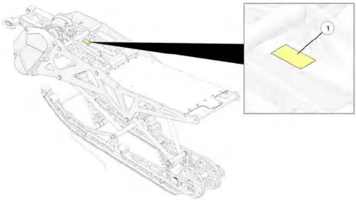
Whenever corresponding about a Timbersled, be sure to refer to the vehicle identification number (VIN) and the serial number. The VIN and serial number decal ① can be found on the top of the chassis. Record your Timbersled's serial number in the spaces provided.
NOTICE
If installing an aftermarket tunnel wrap, do not cover the tunnel serial number with the wrap. If the tunnel wrap doesn't provide an opening for the label, remove the section of wrap where the label is located.
natural_image
Technical line drawing of a mechanical assembly with an inset showing a yellow component labeled '1' (no text or symbols present)① Serial Number
SERIAL NUMBER:
SAFETY
OPERATOR SAFETY
Follow the recommended maintenance program on page 49 to ensure that all critical components on the snow bike are thoroughly inspected at specific intervals outlined in the Periodic Maintenance Chart. Your dealer can perform this service.
WARNING
Driving a snow bike requires your full attention. DO NOT drink alcohol or use drugs or medications before or while driving. They will reduce your alertness and slow your reaction time.
Snow bikes are capable of traveling at high speeds. Use extra caution to ensure operator safety. Make sure your snow bike is in excellent operating condition at all times. Always check major and vital safety components before every ride.
All Timbersled snow bikes are designed and tested to provide safe operation when used as directed. Failure of critical machine components may result from operation with any modifications, especially those that increase speed or power. DO NOT MODIFY YOUR MACHINE. The snow bike may become aerodynamically unstable at speeds higher than those for which it is designed. Loss of control may occur at higher speeds. Modifications may also create a safety hazard and lead to bodily injury.
HOST BIKE
The Timbersled Snow Bike system is designed to be attached to a variety of host bikes. Read and understand your host bike's operation manual and follow all safety and maintenance information. Failure to do so could result in serious injury or death.
STAY CLEAR OF TRACK
Your snow bike is propelled by a revolving track that must be partially exposed for proper operation.
WARNING
Serious injuries may result if hands, feet, or clothing become entangled in the track. Be alert when riding, and remain properly seated to stay clear of the track. Never hold the snow bike up or stand behind it while warming up the track. A loose track or flying debris could cause serious injury or death. We recommend having your dealer perform all track service and alignment procedures.
RIDING POSITION
Operating a Timbersled requires skill and balance for proper control. Rider positions may vary with experience and the features available on some models, but under many conditions the proper position is to be seated with both hands on the handlebar grips for proper throttle, brake, and steering control. See your host bike's owners manual for proper riding position.

WARNING
Improper riding position may reduce control and could result in serious injury or death. Always ride in a position that allows for control of your vehicle.
RIDER CAPACITY
This Timbersled is designed for a single rider only. Never carry a passenger on this vehicle.
RIDING APPAREL
HELMET
Wearing a helmet can prevent a severe head injury. Whenever riding a Timbersled vehicle, always wear a helmet that meets or exceeds established safety standards. Clasp the buckle and pull each strap tight to ensure the helmet is properly secured to the head.
Approved helmets in the USA and Canada bear a U.S. Department of Transportation (DOT) label.
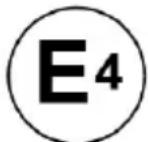
Approved helmets in Europe, Asia and Oceania bear the ECE 22.05 label. The ECE mark consists of a circle surrounding the letter E, followed by the distinguishing number of the country which has granted approval. The approval number and serial number will also be displayed on the label.

051039
0006.31
EYE PROTECTION
Do not depend on eyeglasses or sunglasses for eye protection. Whenever riding a Timbersled vehicle, always wear shatterproof goggles or use a shatterproof helmet face shield. Timbersled recommends wearing approved Personal Protective Equipment (PPE) bearing markings such as VESC 8, V-8, Z87.1, or CE. Make sure protective eye wear is kept clean.
CLOTHING
Be prepared, be warm and be comfortable when riding. Be aware of the weather forecast, especially the windchill, and dress accordingly. See page 23.

WARNING
Avoid wearing loose clothing or long scarves, which can become entangled in moving parts and cause serious injury. Always wear an approved helmet and eye protection.
SURVIVAL PREPARATION
For your safety, always ride in a group. Always tell someone where you're going and how long you expect to be gone. If it isn't possible to ride with others, and you must travel into remote areas, always carry survival equipment that's appropriate to the conditions you may encounter. Such equipment may include, but is not limited to: extra clothing, a sleeping bag, a flashlight, food and water, a signaling mirror, a means of building a fire, and a two-way radio or cellular telephone.
Always carry the owner's manual on your snow bike. For added protection, purchase and carry the following items on your snow bike as well:
- Extra Set of Spark Plugs
- Tow Rope
- Extra Oil
- Fuel Deicer
-
Winter Survival Kit
-
Spare Drive Chain
- Spare Chain Case Chain (if equipped)
- Trail Map
- First Aid Kit
- Tool Kit
EXCESSIVE SPEED
WARNING
High speed driving, especially at night, could result in serious injury or death. Always reduce speed when driving at night or in inclement weather.
Always observe all state and local laws governing snow bike operation and speed limits. Always be alert and pay attention to the trail ahead. If your speed is 40 MPH (64 km/h), your snow bike is traveling about 60 feet (18 m) per second. If you look back for only two seconds, your snow bike will travel about 120 feet (36 m). If your speed is 60 MPH (96 km/h), your snow bike will travel about 180 feet (55 m) in two seconds.
Traveling at night requires extra caution. If your host bike is equipped with a headlight, check headlight and taillight to ensure proper operation, and don't over-drive your headlight beam. Always be able to bring your snow bike to a stop in the distance illuminated by the headlight.
DRIVER AWARENESS
Slow down when traveling near poles, posts, or other obstacles. Be especially alert if you're snow biking after dark. Always be on the alert for wire fences. Single strands are especially dangerous, since there may be a great distance between posts. Guy wires on utility poles are also difficult to distinguish.
Make sure the way is clear before crossing railroads and other roads and highways. The noise of your snow bike will drown out the sound of approaching vehicles. Look ahead, behind, and to both sides before turning or crossing railroad tracks or highways. Steep embankments may also hide your view. Always leave yourself a way out.
Variances in snow depth and/or water currents may result in uneven ice thickness. You may drown if you break through the ice. Never travel on frozen bodies of water unless you have first verified that the ice is sufficiently thick to support the weight and moving force of the snow bike, you and your cargo, together with any other vehicles in your party. Always check with local authorities and residents to confirm ice conditions and thickness over your entire route. Operators assume all risk associated with ice conditions on frozen bodies of water.
When teaching inexperienced operators to ride, set up a predetermined course for practice. Make sure they know how to drive and control the snow bike before allowing them to make longer trips. Teach them proper snow bike courtesy, and enroll them in driver's training and safety courses.
DISABLED OPERATORS
Safe operation of this rider-active vehicle requires good judgement and physical skills. Operators with cognitive or physical disabilities have an increased risk of loss of control, which could result in serious injury or death.
MOUNTAINOUS TERRAIN RIDING
Mountainous terrain operation, even for experienced riders, can present conditions and situations that could result in serious injury or death. Please review all of the information about riding in mountainous terrain on the following pages of this manual.
WARNING
An avalanche can occur at any time, in any conditions and on any slope.
The avalanche information provided in this manual should be considered basic information and is not intended to replace your participation in an avalanche safety training course. After reviewing the avalanche information in this manual, be sure to participate in an avalanche safety training course before riding in mountainous terrain. The training course will provide more information as well as the opportunity to practice riding and using proper search and recovery techniques.
For more information, education, training courses, and links to international resources, visit www.avalanche.org or scan the QR code with your smartphone or other device. See page 18
GET THE SAFETY GEAR
In addition to carrying a spare chain, spark plugs and tools on each snow bike, each person in your riding group should wear the recommended snow bike riding apparel and carry (on their person) the following survival items when riding in mountainous terrain:
- A digital avalanche beacon with new "fresh" alkaline batteries
• An avalanche probe
• A compact shovel and hand saw -
A backpack (preferably an avalanche air bag backpack)
• Emergency provisions, including the following items: -
Small first aid kit
- Extra pair of gloves
- Extra dry socks
- Tow rope, map, compass/GPS
– Lighter or waterproof matches
– Signal mirror and whistle - Bottled water
– High calorie snack food - Compact emergency blanket
- Cell phone
- Radio

natural_image
Product photo of a PPOARE 1+ water safety kit with green and black components (no text or symbols visible)GET TO KNOW YOUR SAFETY GEAR
Following the safety gear and apparel recommendations will increase your chances of survival if you encounter an avalanche or become stranded in the backcountry, but even experienced and properly-equipped snow bikers, hikers and skiers perish in avalanches or succumb to hypothermia. Using a beacon or probe for the first time during an avalanche recovery operation, or not knowing how to deploy your avalanche air bag backpack during a slide, should be considered UNACCEPTABLE to you and all members of your riding group. It's critical that you and all members of your riding group know how to use the safety gear.
While you may know how to use your gear, you may have to rely on your riding group to find you in an avalanche. Make sure they know how to use their gear.
- Dress in layers. Multiple layers of clothing provide the best barrier to cold and wind. Layers can be removed, but if you start out without enough layers, they cannot be added later. Avoid cotton materials, which will freeze if they get wet.
- Wear highly visible gear.
- Try on all gear and equipment to make sure it fits and doesn't interfere with your riding capabilities. Place all survival aids in your backpack and wear the backpack at all times. Non-essential items can be stored on the snow bike in an accessory bag.
- Read and follow the manufacturer's user and maintenance instructions for all gear. If you have questions about how your gear works, contact the manufacturer for more information.
- Practice using your beacons, shovels and probes with your riding group in real-world conditions wearing all of your gear. Have someone hide an active “transmitting” beacon by throwing it (not walking it) into a snowbank and timing your group’s search for it.
- Test deploying your gear. If you own an avalanche air bag backpack, check with the manufacturer's test deployment guidelines and bottle weight replacement specifications. Most air bag backpack manufacturers recommend testing the pack once a year so you know it works and feel comfortable with the bag and deployment time.
- Make sure your probe and shovel are in good condition and that you know how to assemble them.
GET THE PICTURE
Slopes steeper than 30irc are more prone to avalanches, but any slope should be considered avalanche terrain, even small slopes with trees. Low-angle slopes are also avalanche terrain if they have steeper slopes above them.
NOTE
The 30irc slope graphic is for illustration purposes only. The risk of an avalanche is always present in mountainous terrain, regardless of slope angle.
Always look for the following warning signs of unstable snow. If you see or hear any of these signs, riding on or below any slope is dangerous and should be avoided:
- Recent avalanches
- A "whumpfing" sound under a snowpack
- Cracks across the top of a snowpack
• A recent heavy snowfall - Blowing snow
- Rain
- Rapid warming

GET OUT OF HARM'S WAY
- Before riding, always tell a responsible person (i.e. at the lodge or gas station) where your group is going.
- Never ride alone. Always ride in a small, manageable group. Riding in a large group makes it more difficult to track riders or find missing members.
- Go “one at a time”. Only one snow bike at a time should cross, ascend or highmark a slope. Other riders should watch from a safe location until the previous rider exits the slope.
- Never park at the base of a slope or at the bottom of a gully or valley. When parking to take a break or watch other riders, park at the sides of the slope with the front of your snow bike pointed away from the slope.
GET TO KNOW YOUR SNOW BIKE
Because Timbersled snow bikes feature tall track paddles, the rear suspension rails and sliders will sit above the snowpack on a groomed trail. Always deploy the scratchers and limit high speed operation when trail riding.
Always practice riding your snow bike in a safe, open, flat area before attempting your first ride in mountainous terrain. This is especially important for low-elevation riders who are not accustomed to riding a snow bike designed for deep snow.
Do not ride in mountainous terrain until you are comfortable riding and controlling your snow bike in deep snow.
- Practice turning, leaning and braking, both on the trail and off the trail. When you're comfortable with these maneuvers, practice more advanced maneuvers in deep flat snow.
- Learn techniques from more experienced riders.
- Practice traversing through deep snow, which is when you will often need to steer by leaning your body weight in the desired direction.
- Practice using proper throttle control to maintain vehicle momentum and adequate track speed in deep snow. Everyone gets stuck at some point in time. If you know your snow bike is becoming stuck, try to turn downhill as much as you can before the snow bike comes to a stop.
GET THE FORECAST
Make a riding plan based on the current avalanche and weather forecast. It is important to remember that overnight weather conditions may have created unsafe riding terrain that was considered safe the day before. Visit www.avalanche.org or scan the QR code. Follow the page links to locate current avalanche reports and conditions for your area of operation.

GET AVALANCHE SAFETY TRAINING
Timbersled recommends you and all members of your riding group participate in an avalanche safety course. Visit www.avalanche.org/education or scan the QR code for education and training resources.

AVALANCHE AWARENESS
Avalanches are a matter of timing. A steep slope can be safe one day, but unsafe the next day due to changing weather and wind conditions.
- Always review the user instructions provided with your safety equipment and follow the recommendations for maintenance, testing and use. Always test your safety equipment to ensure it works properly before riding in mountainous terrain.
- Always store your survival gear in your backpack and wear the backpack. Do not store your survival gear on the snowmobile.
- Always research current avalanche conditions in your area of operation before riding. Check with local law enforcement, resort or lodging personnel, gas station attendants and other riders to learn about current conditions and any advisories in the area.
- Read and understand the avalanche danger scale. Pay attention to any danger level warnings issued for your area of operation.
- Always remain alert while riding in mountainous terrain. Be aware of snowpack conditions above you as you ride. Avalanches can occur at any time regardless of current condition reports.
North American Public Avalanche Danger Scale
Avalanche danger is determined by the likelihood, size and distribution of avalanches.
| DANGER LEVEL TRAVEL | ADVICE LIKELIHOOD | OF AVALANCHES | AVALANCHE SIZE AND DISTRIBUTION | |
| 5 Extreme |  | Avoid all avalanche terrain. | Natural and human-triggered avalanches certain. | Large to very large avalanches in many areas. |
| 4 High |  | Very dangerous avalanche conditions. Travel in avalanche terrain not recommended. | Natural avalanches likely; human-triggered avalanches very likely. | Large avalanches in many areas; or very large avalanches in specific areas. |
| 3 Considerable |  | Dangerous avalanche conditions. Careful snowpack evaluation, cautious route-finding and conservative decision-making essential. | Natural avalanches possible; human-triggered avalanches likely. | Small avalanches in many areas; or large avalanches in specific areas; or very large avalanches in isolated areas. |
| 2 Moderate |  | Heightened avalanche conditions on specific terrain features. Evaluate snow and terrain carefully; identify features of concern. | Natural avalanches unlikely; human-triggered avalanches possible. | Small avalanches in specific areas; or large avalanches in isolated areas. |
| 1 Low |  | Generally safe avalanche conditions. Watch for unstable snow on isolated terrain features. | Natural and human-triggered avalanches unlikely. | Small avalanches in isolated areas or extreme terrain. |
| Safe backcountry travel requires training and experience. You control your own risk by choosing where, when and how you travel. | ||||
ICE AND SNOW BUILD-UP

WARNING
Ice and snow build-up may interfere with the steering and braking of your snow bike, resulting in serious injury or death. Keep the snow bike free of snow and ice.
Before driving, manually turn the ski to the left and right to be sure ice and snow are not interfering with full left and right steering. If difficulty is encountered, remove ice and snow build-up that may be obstructing the steering.
DRIVING ON SLIPPERY SURFACES

WARNING
Never attempt an abrupt change of direction when operating on slippery surfaces. Proceed slowly and use extra caution. Driving on ice or hard-packed snow reduces steering and braking control, which may result in loss of control and serious injury or death. Slow down and use extra caution when operating on slippery surfaces.
INADEQUATE SNOW CONDITIONS
NOTICE
Driving in too little snow will result in excessive wear and damage to the slide rail, track, ski, ski skags, and/or spindle.

WARNING
Inadequate cooling and lubrication will lead to overheating of the slide rail and track, causing premature wear, damage and failure, which can result in serious injury. Reduce speeds and frequently drive into fresh snow to allow adequate cooling and polishing of the slide rail and track surfaces. Avoid operating for prolonged periods on ice, hard-packed surfaces or roads.
If the snow bike becomes stuck in snow, clear the track and tunnel area of snow, then step down the snow in front of the snow bike so that when the throttle is opened, the snow bike will be able to climb up and over the snow.
DRIVING DOWNHILL
When riding downhill, shift your weight to the rear of the snow bike and reduce your speed to a minimum. Apply just enough throttle to keep the engine from stalling, allowing the engine's compression to help slow the snow bike and keep it from rolling freely downhill.
WARNING
When driving on long downhill stretches, pump the brakes. Riding the brakes may cause the brake system to overheat, which may result in brake failure. Excessive or repetitive use of the brakes for high speed stops will also cause an overheated brake system. This condition may lead to a sudden loss of brakes and/or fire and may result in serious injury or death.
DRIVING IN HILLY TERRAIN
WARNING
Climbing a hill or crossing the face of a slope may result in loss of balance and rollover, causing serious injury or death. Use caution and good judgement when driving in hilly terrain.
Use extra caution when operating in hilly terrain. If climbing a hill is unavoidable, keep your weight low and forward. If you must cross the face of a slope, keep your weight on the uphill side of the snow bike to maintain proper balance and avoid possible roll-over.
Slow down when reaching the crest of a hill. Be prepared to react to obstacles, sharp drops or other people or vehicles that may be on the other side of the hill.
If you're unable to continue up a hill, turn the snow bike downhill before it loses momentum. If this isn't possible, spin the track just enough to dig in to prevent it from rolling back down the hill. Stop the engine. Keeping away from the downhill side of the snow bike, pull the rear of the snow bike around and point the front end and skis downhill. Remount the snow bike, restart the engine, and descend the hill carefully.
Whenever your snow bike has been parked for a length of time, especially overnight, always make sure the ski and track are loosened from ice and snow before attempting to drive. Apply the throttle with enough authority to put the snow bike into motion, but always operate within safety limits.
CAUTION
Reference host bike's owner's manual to insure bike is adequately prepared for cold temperature conditions.
MANEUVERABILITY
While much control and maneuverability is achieved through the steering system and ski, maximum control is achieved by the shifting of your body weight. Maneuverability will change for lighter operators.
DRIVING RESPONSIBLY
Every snow bike handles differently, and even the most benign conditions may become dangerous if operators drive improperly. If you're new to snow biking, acquaint yourself with the snow bike and with what it will and won't do under various conditions. Even seasoned drivers should spend some time getting the feel for a snow bike before attempting ambitious maneuvers.
- A snow bike depends on the rider's body position for proper balance in executing turns, traversing hills, etc. Always start on a smooth, level area to begin building your operating experience.
- Before allowing someone else to use your snow bike, know the extent of their operating skills. Check to see if they've taken a safety course and have an operator's certificate. For their protection, as well as yours, make sure they take a safety course. Everyone can benefit from the course.
- Don't "jump" your snow bike over large drifts or similar terrain. Jumping may injure your back because of spinal compression that could occur when the snow bike impacts the ground. The seat and suspension of your snow bike have been designed to provide protection under normal riding conditions. Your snow bike is not intended for this kind of use.
- Be courteous to oncoming traffic by dimming your headlights (if equipped) and reducing your speed.
- When traveling in a group of snow bikes, don't tailgate (follow too closely). Leave enough distance between snow bikes to provide ample stopping room and to provide protection from flying snow and debris. Allow even more distance when driving on slippery surfaces or when driving in darkness or other low visibility conditions. Be aware of any traffic around your vehicle. Drive defensively to avoid accidents.
- If equipped, remove the key from the ignition when you leave the snow bike unattended.
WINDCHILL/TEMPERATURE CHARTS
The following information is provided to help you determine when temperatures become dangerous for riding.
Safety and warning labels have been placed on the vehicle for the operator's protection. Make sure the operator understands the information on all labels. If any label becomes illegible or comes off, contact your POLARIS dealer for a replacement. Replacement safety labels are provided by POLARIS at no charge. The part number is printed on the label.
The safety labels are located on the tunnel/cowling of your snow bike.
PROPER USE WARNING

natural_image
Blue circular icon with a white open book and lowercase 'i' symbol (no text or numbers)
natural_image
Circular logo with stylized black and white graphic elements, no text or symbols present.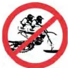
WARNING
Prior to operation, read and understand Timbersled and OEM motorcycle owner's manuals and all warnings.
- ALWAYS wear a DOT approved helmet, eye protection, and protective clothing while operating this vehicle.
• Never carry a passenger. - Before starting engine, check throttle and brake for proper operation.
- Reduce speed and use extreme caution when operating in unfamiliar terrain.
- Ensure that sprocket and track shrouds are in place and secure. Do not operate with shrouds removed.
Failure to follow these instructions could result in severe injury or death. If owners manual is missing contact Timbersled for a replacement.
TOWING WARNING
WARNING
NEVER pull or tow any person or object behind this Timbersled. Objects towed can easily collide with the rear of the track or other objects, resulting in severe injury or death.
NEVER sit on track tunnel. ALWAYS stay clear of track. Entanglement with track can cause severe injury or death.
ACCESSORY WARNING WARNING
Suspension travel reduces distance between exhaust and tunnel. ALWAYS position cargo and accessories to avoid contact with engine, exhaust, or moving components.
FAILURE TO COMPLY MAY RESULT IN SUSPENSION INTERFERENCE OR FIRE AND BURN HAZARD.

natural_image
Mechanical device with chain-like gears and a hand adjusting it (no visible text or symbols)FEATURES
COMPONENT LOCATIONS

① Break Lever
② Exhaust
③ Brake System
④ Tunnel
⑤ Ski Loop
⑥ Spindle
⑦ Ski
⑧ Ski Skags
⑨ Drive Chain
⑩ Chain Case
⑪ Front Track Shock
⑫ Track
⑬ Rear Track Shock
⑭ Rail
⑮ Track Tensioning Block
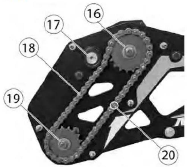
CHAIN CASE COMPONENTS
⑯ Jack Shaft
⑰ Chain Slider/Tensioning Bolt
⑱ Chain Case Chain
⑲ Drive Shaft
⑳ Chain Pin
TOOLS
Timbersled recommends carrying a few tools to work on the snow bike kit when in the backcountry. These tools will take the entire snow bike kit apart.
- Wrenches: 1/2", 8 mm, 9 mm, 10 mm, 13 mm, 14 mm, 15 mm, 16 mm, 17 mm, Adjustable Wrench that adjusts up to 1"
• Hex Keys: 5/32, 7/32 & 1/4 - Torque Key: T27
- Toque Bits
- Bumper Bolts: T45
- Other Tools: Flat blade screwdriver, Pliers
CARGO STORAGE
Never hang heavy items or fuel containers from the rear of the tunnel. Cargo may be stowed only in the tunnel storage bag (if equipped) or another properly used and authorized Timbersled accessory specifically designed for your Timbersled model.
NOTE
Exceeding the tunnel cargo weight capacity could result in tunnel and or suspension pad damage. Do not exceed tunnel weight limit.
RAIL ICE SCRATCHERS
Timbersled recommends rail ice scratchers to help prevent overheating when riding on ice or hard-packed snow.
ACCESSORIES
Timbersled offers a wide range of accessories for your snow bike to help make each ride more enjoyable.

WARNING
Use only Timbersled parts and accessories on your Timbersled snow bike. Use of unapproved parts and accessories may result in:
• Non-compliance with government/industry requirements
- Voiding of warranty
- Injury to self or others
This applies (but is not limited) to the following areas: brakes and fuel storage.
THE PERFECT FIT
SUSPENSION QUICK SETUP GUIDE
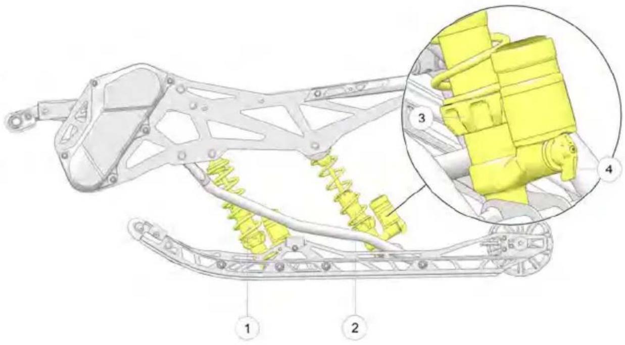
The front ① and rear ② suspensions on your Timbersled snow bike are easy to adjust. Just remember three simple steps:
- Ride your snow bike.
- Adjust the spring preload ③ to tune vehicle balance (ski pressure and weight transfer).
- Adjust shock clickers ④ (if equipped) to tune ride quality (stiffer or softer ride).
The following sections explain how to execute these steps in greater detail according to your specific Timbersled model. For ARO models, move on to the Timbersled ARO Suspension Quick Setup section. For RIOT models, move on to the Timbersled RIOT Quick Setup Guide section.
NOTE
The best suspension setting depends on many variables including the riding terrain and the rider's weight, riding style, and individual preferences.
TIMBERSLED ARO SUSPENSION QUICK SETUP
Step 1: Ride your Timbersled ARO snow bike.
Ride the snow bike on the type of terrain you most often intend to ride to fully experience the existing suspension settings before making any adjustments. Optimal suspension settings can change depending on the terrain you ride.
Step 2: Adjust the spring preload to tune vehicle balance.
CAUTION
DO NOT EXCEED MIN/MAX preload values (as shown in the tables on page 38 and page 38). Failure to comply may result in personal injury or damage to equipment.
After riding, you should be able to determine if the snow bike needs more or less weight transfer and ski to ground pressure. In general, the more spring preload that is added, the less weight will be transferred. Heavier riders, will typically require more spring preload than lighter riders.
NOTE
Always perform shock spring preload adjustments with the weight of the vehicle removed from the shock and the shock at full extension. Make spring preload adjustments in small (approximately 1/16th of an inch) increments and test ride quality between adjustments.
- If your ride requires less weight transfer to the rear suspension, increase the rear track shock's spring preload.
- If your ride requires more weight transfer to the rear suspension, decrease the rear track shock's spring preload.
- If it feels like the ski to ground pressure is too heavy, making it difficult to steer, increase the preload on the front track spring and decrease the preload on the back track spring.
- If it feels like the ski to ground pressure is too light (i.e. the ski lifts from the ground too readily), decrease the preload on the front track spring and increase the preload on the back track spring.
NOTE
For Timbersled ARO bikes with monotube shocks (i.e. shocks with NO clickers), the rear track spring preload can also be decreased to increase ride softness and increased to increase ride stiffness and reduce bottoming out. However, for Timbersled ARO bikes equipped with clickers, using the clickers is typically the best way to adjust for these ride quality characteristics.
Step 3: Adjust shock clickers (if equipped) for ride quality.
For ARO models with shock clickers, you can adjust the clickers to control bottoming and adjust ride comfort.
NOTE
To learn more about compression and rebound damping with shock clickers, see the sections on QS3 Shocks (page 36) and 1.5 Zero LSC-R Shocks (page 37).
- For a softer ride, turn the clicker(s) counter-clockwise to decrease compression or rebound damping.
- For a stiffer ride or to stop bottoming out the front or rear suspension, turn the front or rear track shock clicker clockwise to increase compression or rebound damping.
Test ride the snow bike and continue making small spring and clicker adjustments until you achieve the perfect ride.
NOTE
For improved handling and additional control of the front ski, the Timbersled TRIO front shock can be added to the front forks and spindle of ARO and RIOT models.
TIMBERSLED RIOT SUSPENSION QUICK SETUP
Step 1: Ride your Timbersled RIOT snow bike.
Ride the snow bike on the type of terrain you most often intend to ride to fully experience the existing suspension settings before making any adjustments. Optimal suspension settings can change depending on the terrain type you ride
Step 2: Adjust the spring preload to tune vehicle balance.
CAUTION
DO NOT EXCEED MIN/MAX preload values (as shown in the tables on page 38 and page 38). Failure to comply may result in personal injury or damage to equipment.
After riding, you should be able to determine if the snow bike needs more or less weight transfer and ski to ground pressure. In general, the more spring preload that is added, the less weight that will be transferred. The Timbersled RIOT's front track shock and spring supports most of the bike's weight, while its rear track shock and spring primarily controls ski to ground pressure.
NOTE
Always perform shock spring preload adjustments with the weight of the vehicle removed from the shock and the shock at full extension. Make spring preload adjustments in small (approximately 1/16th of an inch) increments and test ride quality between adjustments.
- If your ride requires less weight transfer, decrease the front track shock's spring preload.
- If your ride requires more weight transfer, increase the front track shock's spring preload.
- If it feels like the ski to ground pressure is too heavy, making it difficult to steer, you can decrease the preload on the rear track spring.
- If it feels like the ski to ground pressure is too light (i.e. the ski lifts from the ground too readily), you can increase the preload on the rear track spring.
NOTE
For Timbersled RIOT bikes with monotube shocks (i.e. shocks with NO clickers), the front track spring preload can also be decreased to increase ride softness and increased to increase ride stiffness and reduce bottoming out. However, for Timbersled RIOT bikes equipped with clickers, using the clickers is typically the best way to adjust for these ride quality characteristics. Ski to ground pressure can also be adjusted with the rear track shock clicker alone or in combination with spring preload settings.
Step 3: Adjust shock clickers (if equipped) for ride quality.
For RIOT models with shock clickers, you can adjust the clickers to control bottoming, adjust for ride comfort, and adjust ski to ground pressure. The clickers on the front track shock should be used to increase or decrease bottoming resistance and ride quality and the clickers on the rear track shock should be used to increase and decrease ski to ground pressure and weight transfer.
NOTE
To learn more about compression and rebound damping with shock clickers, see the sections on QS3 Shocks (page 36) and 1.5 Zero LSC-R Shocks (page 37).
- For a softer ride, turn the front track shock clicker counter-clockwise to decrease compression damping.
-
For a stiffer ride and less bottoming, turn the front track shock clicker clockwise to increase compression damping.
-
To decrease weight transfer, turn the rear track shock clicker clockwise to increase rear shock compression damping
- To increase weight transfer, turn the rear track shock clicker counterclockwise to decrease rear shock compression damping
Test ride the snow bike and continue making small spring and clicker adjustments until you achieve the perfect ride.
NOTE
For improved handling and additional control of the front ski, the Timbersled TRIO front shock can be added to the front forks and spindle of ARO and RIOT models.
TIMBERSLED IFP SHOCKS
natural_image
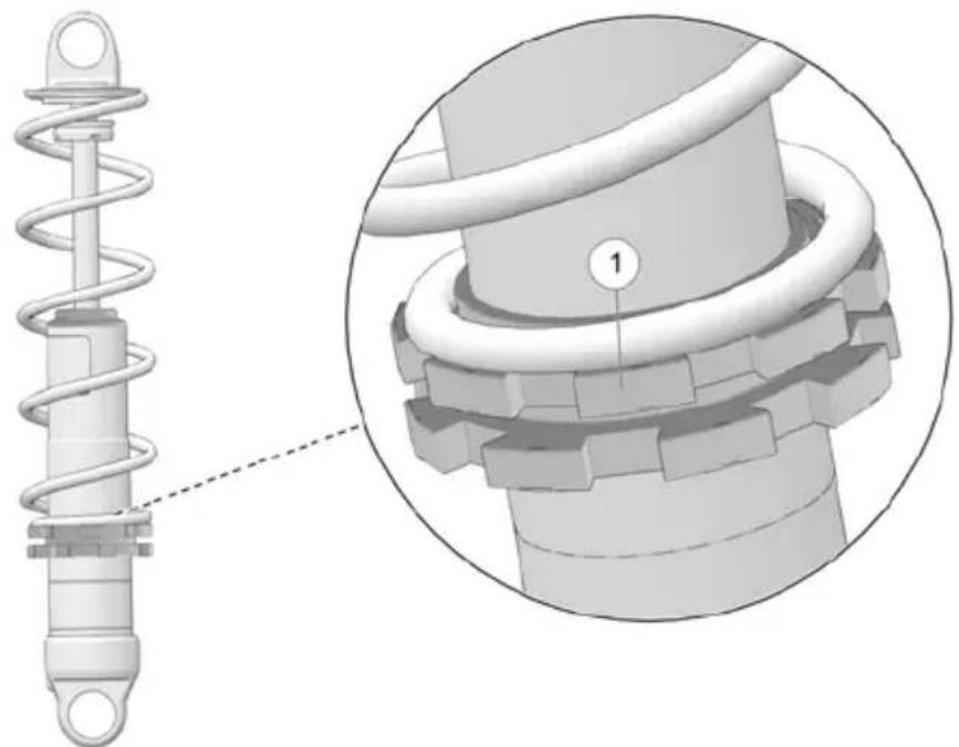
Mechanical assembly diagram showing a spring and gear component with a magnified inset highlighting a specific part (no text or symbols present)All standard ARO and RIOT models have Timbersled Internal Floating Piston (IFP) Shocks for both front track and rear track. Timbersled IFP shocks are spring preload ① adjustable ONLY as they do not have clickers for adjusting compression and rebound damping. Although the factory spring preload settings are usually sufficient for most riders, if you find adjustment is needed, NEVER adjust the spring preload beyond the minimum and maximum spring preload settings (see page 38 and page 38).
NOTE
A spanner wrench (Part Number: 2871095–329) is needed to adjust the Timbersled IFP shock spring preload.
FOX QS3 SHOCKS
natural_image
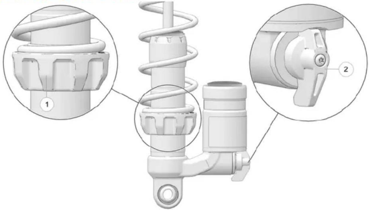
Technical illustration of a mechanical spring assembly with close-up views of internal components (no text or symbols)All Timbersled ARO LE and RIOT LE Models, including the Timbersled 3" Model, have QS3 shocks for both front track and rear track. Fox QS3 Shocks are spring preload adjustable ① and have clickers ② for adjusting compression damping. Remember to adjust your snow bike's spring preload first, before moving on to adjust the clickers. If spring preload adjustment is needed, never adjust the QS3 shocks beyond their Min/Max preload values (seepage 38 and page 38). Compression damping slows down (i.e. dampens) the shock compression that happens when the snow bike hits a dip, bump or other disturbance. The higher the compression damping, the slower the shocks will compress when encountering a disturbance.
QS3 clickers have the following three positions:
-
1 Soft: Turn the clicker all the way to it's farthest counterclockwise position to achieve a softer or more plush ride with the least amount of compression damping.
-
2 Medium: Turn the clicker one click clockwise from its soft position to achieve a intermediate ride (between plush and stiff) with a medium amount of compression damping.
-
3 Stiff: Turn the clicker two clicks clockwise from it's soft position for a stiffer ride with the highest amount of compression damping.
TIP
When ascending steep inclines with the Timbersled RIOT LE, temporarily turn the rear track clicker on the QS3 shocks clockwise to it's highest compression damping setting to help the ski remain in contact with the ground during the ascent.
Timbersled ARO 120 SX Models, have FOX 1.5 Zero LSC-R Shocks for both front and rear track. In addition to being spring preload adjustable①, Fox 1.5 Zero LSC-R Shocks have 2 clickers which adjust compression damping② and rebound damping ③. Remember to adjust your snow bike's spring preload first, before moving on to adjust the clickers. If spring preload adjustment is needed, never adjust 1.5 Zero LSC-R shocks beyond their Min/Max preload values (see page 38 and page 38).
Compression damping and rebound damping work hand-in-hand to provide a softer or stiffer ride. Increasing compression damping creates a stiffer ride by slowing down (i.e. dampening) the shock compression that happens when your bike hits a dip, bump or other disturbance. Increasing rebound damping also creates a stiffer ride by causing the shocks to rebound (i.e. extend back to their normal position) more slowly after compressing when the bike hits a disturbance. Too much rebound damping on bumpy terrain may not allow the shocks to recover quickly enough after a bump to allow the shock to be ready for the next bump.
The 1.5 Zero LSC-R shock clickers have a total of 24 compression damping clicker positions and a total of 25 rebound damping clicker positions which allows for more minute changes and finer tuning of ride quality. The shock clickers can be turned all the way counterclockwise for a softer or plusher ride with the least amount of compression or rebound damping and can be turned all the way clockwise for the stiffest ride with the most amount of compression or rebound damping. Keep in mind that adjustments to the spring preload will require you to reset the compression and rebound damping to find the best settings once again.
NOTE
After setting the spring preload, it is suggested that you start with both compression and rebound damping set at their softest settings (i.e. clickers turned all the way counterclockwise) and slowly try out more compression and rebound damping until you achieve your perfect ride.
FRONT TRACK SHOCK SPRING SETTINGS
Factory settings, combined with user adjustments to the front track shock spring, should be sufficient in providing the best riding experience for most riders. Always perform shock spring preload adjustments with the weight of the vehicle removed from the shock and with the shock at full extension.
NOTICE
Never adjust spring preload to an installed length longer than the factory length or shorter than the minimum length as shown in the following chart. Damage to the suspension could result. When decreasing preload, make sure at least two turns of preload are holding the retainer against the spring.
| MODEL FRONT | SHOCK | SPRING RATE | FACTORY INSTALLED LENGTH | MIN. ALLOWABLE INSTALLED LENGTH |
| RIOT 120 Timbersled IFP | 250 | 8-1/2" 8-1/4" | ||
| RIOT 120 LE | FOX QS3 250 | 8-1/2" 8-1/4" | ||
| ARO 129 Timbersled IFP | 150 | 7-13/16" 8-7/16" | ||
| ARO 129 LE ARO 129 LE 3" ARO 137 LE | FOX QS3 150 | 7-3/4" 7-7/16" | ||
| ARO SX 120 FOX 1.5 ZERO LSC-R | 200 | 7-13/16" 7-9/16" |
REAR TRACK SHOCK SPRING SETTINGS
Always perform shock spring preload adjustments with the weight of the vehicle removed from the shock and with the shock at full extension.
NOTE
If adjustments to the factory-installed springs are not sufficient for riders over 300 lbs. (136 kg), optional stiffer springs are available. Your Timbersled dealer can assist.
| MODEL REAR | TRACKSHOCK | SPRINGRATE | FACTORYINSTALLEDLENGTH | MIN.ALLOWABLEINSTALLEDLENGTH |
| RIOT 120 TimbersledIFP | 80 8–1/2” 7” | |||
| RIOT 120 LE FOX QS3 80 8–1/2” 7” | ||||
| ARO 129 TimbersledIFP | 175 7–13/16” 8–7/16” | |||
| ARO 129 LEARO 129 LE 3”ARO 137 LE | FOX QS3 175 7–7/8” 7–7/16” | |||
| ARO 120 FOX 1.5ZERO LSC-R | 200 7–13/16” 7–9/16” | |||
TSS SHOCK TUNING
The TSS suspension system is intended to work in harmony with the in track rear suspension to create a dual rear suspension feel that is unique to a Timbersled snow bike. It is not intended to have a soft squishy feel like the stock motorcycle rear suspension, and it's important that you do not try to tune it to feel this way. For maximum suspension performance follow the tuning instructions.
The TSS shock is preset from the factory with 260 psi. Use a Fox Float air pump to adjust the spring rate and preload of the TSS shock. Your shock will have a sticker on it with the minimum, maximum and factory pressure settings.
| Suggested TSS Pressures | |
| Setting PSI | |
| Minimum Setting 200 | |
| Factory Setting 260 | |
| Maximum Setting 400 | |
To tune the TSS shock:
- Take the weight off the shock by lifting the bike from under the engine or tipping it on its side.
-
Remove the shock's silver valve cap.
-
Thread the pump onto the shock's valve-stem until the pump pressures up and you are able to see the supplied pressure on the gauge.
NOTE
When the pump pressures up the shock instantly loses 20 psi from the volume it takes to fill the pump hose. You will need to compensate for this when checking pressures.
- When finished, unthread the pump. You will hear a release of air when unthreading the pump, but this will not affect the exact pressure you gave the shock.
NOTE
When tuning your TSS shock, it is best to add or subtract air pressure in increments of 25 psi at a time. Be very careful to not get snow or water inside the valve stem; this can cause the shock to leak air.
- For a more refined tuning method, you may use the TSS shock O-ring which can be found on the outer shock body. The O-ring is designed to be a gauge for measuring the amount of shock travel you are using when riding.
To measure the amount of shock travel:
- Slide the O-ring down to it's lowest point.
- Ride the snow bike for approximately 10 minutes.
- Stop the bike and measure the amount the O-ring has moved. To measure O-ring movement, measure the distance between the O-ring's starting point (when moved down to it's lowest point) and the O-ring's current location (after a 10 minute ride).
The O-ring movement equals the amount of TSS shock travel. The TSS shock has a max travel distance of 1.5" to bottom out. It is recommended that the targeted amount of shock travel be about 1-1/8" of stroke. - Tune the TSS shock in increments of 25 psi to reach the targeted amount of shock travel (1-1/8") and accomplish perfect calibration.
NOTE
Each time you make a pressure adjustment (of 25 psi), slide the O-ring back down to its lowest point and ride for approximately 10 minutes before rechecking your shock travel distance.
PRE-RIDE INSPECTION
PRE-RIDE CHECKLIST
Inspect all items on the checklist for proper operation or condition before each use of the snow bike. Procedures are outlined in the referenced sections.
| ITEM SEE SECTION | |
| Steering System page 43 | |
| Coolant Level See Host Bike's Owners | Manual |
| Injection Oil Level See Host Bike's Owners Manual | |
| Ignition Switch See Host Bike's Owners Manual | |
| Headlight/Taillight/Brakelight See Host | Bike's Owners Manual |
| Suspension Mounting Bolts page 31 | |
| Skags (Wear Bars) page 70 | |
| Ski Saddle and Spindle Bolts page 72 | |
| Track Alignment/Condition page 63 | |
| Rail Slide Condition page 72 | |
| Chain Tension page 52 and page 56 | |
PRE-RIDE SUSPENSION INSPECTION
Loose nuts and bolts can reduce your snow bike's reliability and cause needless repairs and down time. Before beginning any ride, a visual inspection will uncover potential problems. Check the following items on a weekly basis or before any long trip.
| ITEM SEE SECTION | |
| Check suspension mounting bolts for tightness. | - |
| Check rear idler wheel bolt for tightness. | page 44 |
| Check rear idler adjusting bolt locknuts for tightness. | - |
| Check rail slide condition. page 72 | |
| Check track tension. | - |
| Check ski runner/skag condition. page 70 | |
| Check ski spindle bolts for tightness. | - |
| Swing Arm Pivot Bolt | - |
| Check chains (chain case and engine drive chain) for wear and tension. | page 56 |
BEFORE STARTING THE ENGINE
Before starting the engine, reference your host bike's owner's manual for engine starting process and safety warnings.
WARNING
Operating the vehicle with worn, damaged, or malfunctioning components could result in serious injury or death. Never start the engine without checking all vehicle components to be sure of proper operation.
READ AND UNDERSTAND YOUR OWNER'S MANUAL
Read your Timbersled owner's manual, as well as your host bike's owner's manual, completely and refer to it often. The manual is your guide to safe and enjoyable experience.
STEERING SYSTEM
WARNING
Ice and snow build-up may interfere with the steering of your snow bike, resulting in serious injury or death. Keep the vehicle free of snow and ice.
Before driving, manually turn the ski to the left and right to be sure ice and snow are not interfering with full left and right steering. If difficulty is encountered, remove ice and snow build-up that may be obstructing the steering linkage or front ski and skags.
Ensure fork clamps, spindle and ski bolts, and front axle bolt are torqued properly.
BRAKES
Always check the following items for proper operation before starting the engine.
BRAKE LEVER TRAVEL
Squeeze the brake lever. It should move no closer to the handgrip than 1/2 inch (1.3 cm). A smaller distance indicates low brake fluid level or air in the hydraulic system. Your dealer can assist.
LEVER FEEL
If the brake lever feels “spongy” when squeezed, check the brake fluid level and condition.

WARNING
Continued use of “spongy” brakes may cause a complete loss of brakes, which could result in serious injury or death. Always have the brakes serviced at the first sign of sponginess.
NOTICE
To gain 100% braking performance, Timbersled recommends performing 20–50 stop cycles of the Timbersled Brake System before first ride. Brake cycles should be performed at a slow controlled speed in a flat, open environment. Starting the snowbike and engaging it into gear, allow the track to spin 3–5 full rotations. Apply moderate pressure to the brake until the track is completely stopped and is no longer spinning. Repeat as necessary.
TRACK
Track damage or failure caused by operation on ice or poor lubrication conditions voids the track warranty.

WARNING
Operating the snow bike with a damaged track increases the possibility of track failure, which could cause loss of control resulting in serious injury or death. Always inspect the track for damage before using the vehicle.
CAUTION
Use of traction products such as studs increases the possibility of track damage and/or failure. Driving at high speeds for extended periods of time in marginal lubrication could severely damage track rods, break track edges, and cause other track damage. Examples of marginal lubrication would include frozen bodies of water without snow cover, icy trails, and no-snow conditions.
OPERATION
BREAK-IN PERIOD
SNOW BIKE SYSTEM BREAK-IN
| BREAK-IN FUNCTION BREAK IN PERIOD (HOURS OF ENGINE RUN TIME) | POST BREAK-IN MAINTENANCE | |
| Chain: Drive and Chain Case 3 hours | Lubricate | |
| Chain Deflection (Drive and Chain Case)note: follow chain tensioning procedures onpage 56 and page 60. | 3 hours | Check Tension |
| Brake Line Connections 3 hours | Check for leaks | |
| Track Tension 3 hours Check Tension | ||
| Swing Arm Bolt 3 hours Re-Torque | ||
| Strut Rod Bolts 3 hours Re-Torque | ||
| Front Axle 3 hours Re-Torque | ||
| Ski Bolt 3 hours Re-Torque | ||
Drive with extra caution during the break-in period. Perform regular checks on fluid levels, lines, and all other important areas of the snow bike.
TRACK WARM-UP
WARNING
A loose track or flying debris could cause serious injury or death. Stand clear of the front of the snow bike and the moving track. Never hold the snow bike off the ground or stand behind it while warming up the track. Do not use excessive throttle during warm-up or when the track is free-hanging. Use a stable rear support.
WARNING
Use of traction products such as studs, ice growsers, etc. will increase the possibility of track damage and/or failure. This could cause loss of control, resulting in serious injury or death. Always inspect for track damage before operating the snow bike.
Follow these steps to ensure proper warm-up of the engine, drive train and track.
- Use an appropriate stand to securely support the rear of the snow bike. The track should be about 4 inches (10 cm) off the ground.
- Start the engine and allow it to warm up two to three minutes.
- Engage the throttle abruptly and allow the track to rotate several revolutions.
TIP
It will take longer to warm up the track sufficiently during colder outdoor temperatures.
-
Release the throttle, apply the brakes, shut off the engine and lower the snow bike to the ground.
-
Grasp the ski by the front loop and move it from side to side to loosen snow and ice.
SLIDE RAIL AND TRACK COOLING
NOTICE
Inadequate cooling and lubrication will lead to overheating of the slide rail and track, resulting in premature wear and failure. Reduce speeds and frequently drive into fresh snow to allow adequate cooling and polishing of the slide rail and track surfaces. Avoid operating on ice, hard-packed surfaces or roads.
Deep lug tracks are designed specifically for operation in deep snow conditions. Operation with deep lug tracks on low snow, hard-packed trails, ice, or at sustained high speeds may cause track overheating, track lug separation, and/or rail slide damage.
NOTICE
Track damage attributed to track overheating and/or lug separation is not covered under the Timbersled limited warranty policy.
IMPORTANT
Timbersled ARO 3" models have a recommended maximum sustained speed limit of 50 MPH. To avoid track/lug damage, never exceed this maximum recommended sustained speed.
FUEL STORAGE

WARNING
Gasoline is highly flammable and explosive under certain conditions.
• Always exercise extreme caution whenever handling gasoline.
- Always follow the safety procedures outlined in your host bike's owner's manual.
• Always refuel outdoors or in a well-ventilated area.
• Always turn off the engine before refueling.
- Do not overfill the tank. Do not fill the tank neck.
- Do not smoke or allow open flames or sparks in or near the area where refueling is performed or where gasoline is stored.
- If gasoline spills on your skin or clothing, immediately wash it off with soap and water and change clothing.
- Never start the engine or let it run in an enclosed area. Engine exhaust fumes are poisonous and can cause loss of consciousness or death in a short time.
FUEL RECOMMENDATION
See host bike owner's manual for fuel recommendation.
NOTICE
Operating with obstructed fuel systems will result in serious engine damage. Perform maintenance as recommended. Prolonged exposure to petroleum based products may damage paint. Always protect painted surfaces when handling fuel.
DAILY STORAGE
At the end of each ride, park the vehicle on a level surface and support it at the rear with an appropriate track stand. The track should be suspended approximately 4 inches (10 cm) off the ground.
Remove the key (if applicable) and cover the vehicle.
MAINTENANCE
For host bike maintenance procedures and recommendations, refer to your host bike's owner's manual. The maintenance information found in the manual only applies to the Timbersled Snow Bike system.
TIMBERSLED RECOMMENDED MAINTENANCE PROGRAM
Always follow recommended regular maintenance and perform service checks as outlined in this manual. Record maintenance and service in the Maintenance Log.
The recommended maintenance schedule on your vehicle calls for service and maintenance inspections at 150 miles (240 km), 500 miles (800 km) and 1000 miles (1600 km). These inspections should be performed by a qualified service technician. For continued optimum performance and component life, continue maintenance checks at 1000 mile (1600 km) intervals.
All necessary replacement parts and labor incurred, with the exception of authorized warranty repairs, become the responsibility of the registered owner. If, during the course of the warranty period, part failures occur as a result of owner neglect in performing recommended regular maintenance, the cost of repairs are the responsibility of the owner.
Personal safety is critical when attempting to service or make adjustments to your vehicle. If you're not familiar with safe service or adjustment procedures and the use of tools, or if you don't feel comfortable performing these tasks yourself, your authorized Timbersled dealer can provide any needed service.
NOTICE
Hot components can cause damage to plastic. Always make sure the exhaust system and engine have cooled before tipping the vehicle on its side for service or inspection.
NOTE
Timbersled recommends changing the oil in your host bike more frequently that stated in the host bike's owners manual.
PERIODIC MAINTENANCE TABLE
The following chart is a guide based on average riding conditions. You may need to increase frequency based on riding conditions. When inspection reveals the need for replacement parts, always use genuine Timbersled parts, available from your Timbersled dealer.
| I - INSPECT (CLEAN, ADJUST, TIGHTEN, LUBRICATE, REPLACE IF NECESSARY)C - CLEAN, R - REPLACE, L - LUBRICATE | ||||||
| ITEM | FREQUENCY | |||||
| 150 MI.(240 KM) | 500 MI.(800 KM) | 1000 MI. (1600 KM) | 2000 MI. (3200 KM) | PRE- SEASON | ||
| BRAKES | ||||||
| Hose Routing | ||||| | |||||
| Hose Condition | ||||| | |||||
| Fluid Leaks | ||||| | |||||
| Brake Pads | ||||| | |||||
| Brake Disc | ||||| | |||||
| Brake System (see page 54 for inspection procedures) | ||||| | |||||
| Brake Fluid | III | |||||
| FUEL MANAGEMENT | ||||||
| Air Box/Air Intake | ||||| | |||||
| CHASSIS | ||||||
| Chassis Mount Bushings | R R I/L | |||||
| Suspension Mounting Bolts | ||||| | |||||
| Steering Fasteners | ||||| | |||||
| Rear Suspension Fasteners | ||||| | |||||
| Ski Saddle/Spindle Bolts | ||||| | |||||
| Drive Chain (see page 56 and page 61 for inspection and tensioning procedures) | I/L I/L R | R I/L | ||||
| Rear Wheel Idler Bolt | | | | | | | |||||
| Idler Bolt Jam Nut | | | | | | | |||||
| Track Alignment | | | | | | | |||||
| Track Tension | | | | | | | |||||
| Rail Slide Condition (seepage for inspectionprocedures) | | | | | | | |||||
| Chain Case Chain (see page 60and page 61 for inspection andtensioning procedures) | I/L I/L R | R I/L | ||||
| Fork Clamp Bolts | | | | | | |||||
| Swing Arm Bolts | | | | | |||||
| Strut Rod Bolt | | | | | | |||||
| Front Axle Bolt | | | | | | |||||
| Chain Guide Slider | I I R R | I/R | ||||
| Ski Skags (see page 70 forinspection procedures) | | | | | | | |||||
| RearSuspensionArm Bushings(if equipped—grease withgrease fittings) | | | | | | | |||||
LUBRICATION
CHAIN LUBRICATION
Lubricate the chains every 8 to 10 hours of operation. We have found that the use of Maxima Chain Wax for O-ring chains works best. It is recommended to lift the track off the ground. Start the bike and put it into first gear and let the clutch out allowing the drive system to spin. Slowly spray lube directly onto the chain rollers and O-rings, soaking the chain. This will allow good penetration into the moving chain parts.
TRACK LUBRICATION
The slide rail needs snow for lubrication. Excessive wear indicates insufficient lubrication. A new rail slide can cause faster heat build-up in limited lubrication, resulting in excessive wear.

WARNING
Operating with insufficient lubrication between the rail slide and track guide clips can cause track failure, loss of vehicle control and loss of braking ability, which can result in serious injury or death. Avoid operating for extended periods on ice and other surfaces that have little or no snow for lubrication.
If excessive rail slide wear occurs due to poor snow conditions, additional scratchers are available specifically designed for your model. Your dealer can provide more information.
Track damage or failure caused by operation on ice or under other poor lubrication conditions will void the track warranty.
EXHAUST SYSTEM
For exhaust system inspection procedures, see your host bike's owner's manual.
CAUTION
Hot exhaust system parts can cause burns. Allow adequate time for the exhaust system to cool. Never perform this procedure with the engine running.
SUSPENSION
SUSPENSION MAINTENANCE
The following procedures should be performed regularly to properly maintain the suspension of your snow bike.
- Track tension and alignment adjustment may be required if the track starts to skip on the drivers or if the rail slides are wearing too quickly. For more information on track tension and alignment refer to the Track Maintenance section (page 63).
- Inspect rail slides regularly for wear and replace them if they have thin spots. Rail slide wear can be prevented by making sure snow is spraying on them when riding on the trail. It is recommended to install ice scratchers on the rails if frequently riding on hard pack snow conditions. The rails are pre drilled for this. Ice Scratchers and rail slides can be purchased through Timbersled or most snow bike shops. For more information on rail slide inspection and wear see the Rail Slide Wear section (page 72).
NOTE
Replacement rail slides are the same profile as late model Timbersled snow bikes.
- Timbersled RIOT models' rear suspension arm is equipped with grease fittings. The suspension comes with assembly grease on the bushings that should last until the first maintenance period. Lubricate as necessary and at the maintenance intervals indicated on the Periodic Maintenance chart (page 50).
BRAKES
Inspect the brake lever reserve before each use of the snow bike. See page 44.
Brake pads must be replaced when the brake pad material becomes thinner than 1/16 inch (1.5 mm). A kit is available for replacing brake pads. Your Timbersled dealer can assist.
WARNING
Brake failure during operation can result in serious injury or death. Properly functioning brakes are vital to your safety. Be sure the brake pads do not drag on the disc and that brake lever travel is not excessive. Always replace brake pads when the brake pad material becomes thinner than 1/16 inch (1.5 mm).
BRAKE COMPONENTS


natural_image
Circular object with scalloped edges and a central hole, labeled with number 3 (no text or symbols on the object itself)① Brake Caliper
② Brake Pad Material
③ Brake Disc
EXCESSIVE LEVER TRAVEL
Hydraulic brakes are self-adjusting, but if excessive brake pad clearance develops, bring the snow bike to an authorized Timbersled dealer for inspection and adjustment.
TIP
The lightweight brake discs have vent holes that may cause a high-pitched sound during operation.
BRAKE FLUID
The brake fluid level can be seen through a plastic sight glass in the brake reservoir. If the fluid is sufficient, the sight glass will be black. If the sight glass is any color other than black, add brake fluid.
Replace brake fluid at least every two years with DOT 4 high temperature brake fluid, or an equivalent product.
WARNING
After opening a bottle of brake fluid, always discard any unused portion. Never store or use a partial bottle. Brake fluid is hygroscopic, meaning it rapidly absorbs moisture from the air. The moisture causes the boiling temperature of the brake fluid to drop, which can lead to early brake fade and the possibility of accident or serious injury.
WARNING
Keep the master cylinder cover free of dirt and debris. The vent slits allow for diaphragm movement, and if they become plugged, movement of brake fluid below the diaphragm may be restricted, altering brake function.
NOTICE
Brake fluid will damage labels, paint and some plastics. Always wipe up spills immediately.
Air in the hydraulic brake system will cause spongy brake lever action. If the brakes feel spongy, bleed the system before operating the snow bike.
WARNING
Operating the vehicle with a spongy brake lever can result in loss of brakes, which could cause an accident and lead to serious injury or death. Never operate the vehicle with a spongy-feeling brake lever.
During the bleeding procedure, keep the brake handle as level as possible. The reservoir must be in this position to minimize the possibility of air entering the system through the reservoir vent.
- Remove the brake master cylinder reservoir cover and gasket.
- Fill the master cylinder reservoir to between the MIN and MAX marks or 1/4-5/16 inch (.6-.8 cm) below the lip of the reservoir opening. Reinstall the gasket and cover.
- Slip a rubber tube over the ball of the bleeder valve and direct the flow of fluid into an approved container.
- Squeeze the brake lever a full stroke. Then unscrew the bleeder valve 3/4 of a turn to release air.
- Close the bleeder valve and release the brake lever.
- Repeat steps 4–5 until fluid flows from the bleeder valve in a solid stream free of air bubbles.
WARNING
Overfilling the master cylinder leaves no room for fluid expansion and may cause the brakes to lock, resulting in serious injury or death. Always add brake fluid to the fill line as recommended.
- After bleeding is complete, refill the reservoir to the proper level.
- Reinstall the gasket and cover.
TORQUE
6–8 in lbs (0.7–0.9 Nm)
DRIVE SYSTEM
DRIVE CHAIN TENSION
For long chain life and reliability, it is extremely important that you keep the drive chain adjusted properly. Always check drive chain tension before riding.
IMPORTANT
TIMBERSLED SUSPENSION STRUT (TSS) MODELS: The TSS MUST be at full extension and set to at least 200 PSI to measure and adjust drive chain tension properly. To ensure the TSS is at full extension, remove all weight from the shock. Inspecting and adjusting a chain without the suspension at full extension will indicate a loose chain and lead to over-tensioning and excessive chain stretch and wear.
NOTE
The drive chain may loosen on the first ride due to initial chain stretch and slider break-in. Retighten drive chain after the first few rides. If the problem persists, your dealer can assist.
MEASURING DRIVE CHAIN TENSION
To measure drive chain tension before riding:
- Ensure your snow bike is free of all snow and debris, positioned on a flat even surface, and has no wheel kit positioned under it.
For Timbersled Suspension Strut (TSS) models, set TSS shock air pressure to at least 200 PSI. Then ensure TSS suspension is at full extension (i.e. no weight is on the shocks) by tipping the bike on its side or by using an appropriate stand to lift the bike under its engine ensuring the track is suspended off the ground.

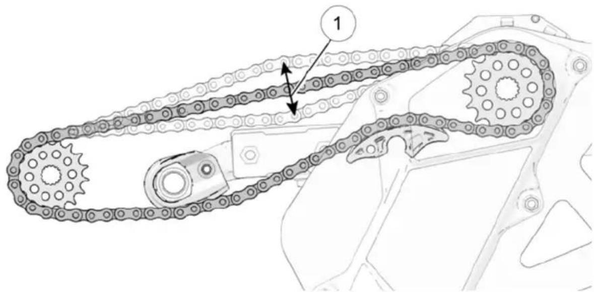
- Position a ruler behind or in front of the top chord of the drive chain, halfway between the counter shaft sprocket and the jack shaft sprocket (this is where drive chain displacement should be measured)①. Steady the ruler so it does not move as chain displacement is measured.
-
Choose a single chain link pin close to the ruler to use as a reference point for measuring chain displacement. Push down on the top chord of the chain with one finger and line up the 1 inch mark on the ruler with the chosen chain pin ② (see photo).
-
Then, without moving the ruler, push up on the top chord of the chain with one finger in the same location and count the number of 1/8 th in. marks between the 1 inch mark and the new position of the chosen chain pin③.
If the chain is properly tensioned, there should be between 0.75 in. and 0.25 in. between the 1 inch mark (the position of the chosen chain pin when pressed down) and the current position of the chosen chain pin (when pressed up). This is the drive chain's displacement measurement. If the drive chain's displacement measurement is less or more than 0.75 in. and 1.25 in. the chain needs to be adjusted (see Adjusting Drive Chain Tension).

natural_image
Close-up of a mechanical component with a ruler and numbered annotation (no readable text or symbols)
ADJUSTING DRIVE CHAIN TENSION
To adjust drive chain tension, follow the steps below.
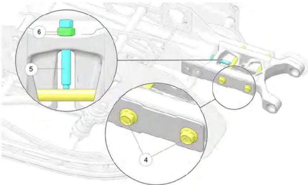
- If the chain needs to be adjusted, loosen both 15 mm frame rail slide bolts ④ located on the right side of the Timbersled.
- Next, loosen the 13 mm inner jam nut ⑥ on the inner frame tension adjuster bolt ⑤.
- Adjust the tension adjuster bolt ④ in or out to achieve the correct chain tension.
- Re-torque the jam nut ⑥ to 25 Nm.
- Re-torque the frame rail slide bolts ④ to 50 Nm .
- Measure the drive chain's displacement once again to ensure it is properly adjusted.
If the chain is too tight and the frame is difficult to compress, you may loosen the front right-hand side panel bolt ⑦ and the front right-hand frame bolt ⑧ to allow the frame to slide easier. Re- torque both bolts to 60 Nm prior to tensioning the chain.

CHAIN CASE CHAIN TENSION
It is recommended that you measure the chain case chain tension each time the chain is lubricated.
CAUTION
Do not over-tension the chain. Improper chain tension can cause excessive wear to the chain and the tension roller bolt.
MEASURING CHAIN CASE CHAIN TENSION
To measure the chain case chain's tension:
- Remove the fasteners that hold the chain case cover on.
- Position a ruler behind or in front of the right chord of the drive chain halfway between the drive shaft sprocket④ and the jack shaft sprocket② (this is where the chain's displacement should be measured). Position and steady the ruler so it does not move as chain displacement is measured.
- Choose a single chain link pin close to the ruler to use as a reference point for measuring chain displacement. Push the chain's right chord to the left near the chosen link pin using 1 finger. Line up the 1 inch mark on the ruler with the center of the chosen chain pin.
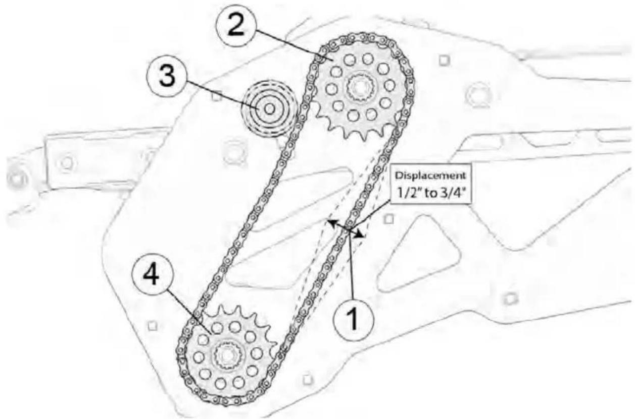
- Then, without moving the ruler, push the chain's right chord to the right with one finger in the same location and count the number of 18 marks between the 1 inch mark and the new position of the chosen chain pin.
If the chain is properly tensioned, there should be between 12 " and 34 " between the 1 inch mark (the position of the chosen chain pin when pressed to the left) and the current position of the chosen chain pin (when pressed to the right). This is the chain case chain's displacement measurement①. If the chain's displacement measurement is less or more than 12 " to 34 ", the chain tension needs to be adjusted (see Adjusting Chain Case Chain Tension).
ADJUSTING CHAIN CASE CHAIN TENSION
To adjust the chain case chain's tension:
- Loosen the tension roller bolt ③.
- Adjust the chain tension as needed by pushing the roller bolt③ towards the chain to increase tension or away from the chain to lessen tension.
- Then tighten the tension roller bolt ③ firmly once again.
- Measure the chain case chain's displacement ① once more to ensure proper adjustment.
CHAIN INSPECTION
IMPORTANT
Regular drive chain and chain case chain inspection is important. A broken chain can cause host bike damage.
Chains need to be regularly inspected for signs of wear, damage and stretching. A drive chain or chain case chain that has stretched 1% or more of its length is worn out and will need to be replaced.
NOTE
A chain with 1000 miles or 75 hours of use will need to be replaced (see Periodic Maintenance Interval Table on page 50).
To measure chain stretch, perform the following procedure:
- To determine whether the chain has stretched 1% or more, first ensure the chain is taut along the area you plan to measure (a screw driver ② is used to keep the drive chain taught in the drive chain image below).
Timbersled RIOT and ARO snow bikes are equipped with 520 drive and chain case chains which have a pitch of 58 or 0.625" (A chain's pitch is the length of a single link which is measured from the center of one pin to the center of the next pin ①).

- Mark out the number of links to measure (see the following table to find the number of links to measure for the chain you are inspecting). To mark this number of links, begin by marking the first pin③ and counting forward the same number of pins (number of pins counted should equal the number of links to measure). Finish by marking the final pin④. (see image with first and last pin marked).

| CHAIN TYPE | # OF LINKS TO MEASURE | EXPECTED LENGTH | EXPECTED LENGTH +1% | ACCEPTABLE LENGTH RANGE |
| Drive Chain 24 | (mark first and last pin) | 15”(24 x 0.625 = 15) | 15.15” or slightly < 15 18 ” | Between 15” and 15.15” |
| Chain Case Chain | 17(mark first and last pin) | 10.625” or 10 58 ”(17 x 0.625 = 10.625) | 10.731” or slightly < 10 34 ” | Between 10.625” and 10.731” |
-
Then measure the counted number of links by measuring from the center of the first pin ③ to the center of the final pin ④. This measurement should equal a length somewhere within the acceptable length range (as shown in the previous table).
-
If the length of the counted chain links equals or exceeds the expected length plus 1% (see table) the chain is worn out and must be replaced.
If the length of the chain links is less than the expected length plus 1% (i.e. the length is within the acceptable length range), the chain does not need to be replaced at this time.
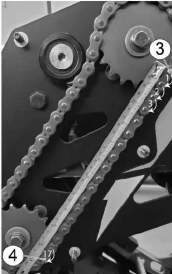
- Using a hoist, safely lift and support the rear of the snow bike off the ground.
- Rotate the track by hand to check for damage.
- Carefully examine the track along the entire length of each rod. Bend the track to check for breakage.
- Replace the track if any rod damage is found.
WARNING
Broken track rods can cause a rotating track to come off the snow bike, which could cause serious injury or death. Never operate with a damaged track. Never rotate a damaged track under power.
TRACK ALIGNMMENT
Proper track alignment is an essential factor in proper snow bike handling and in preventing excessive wear to the track and rail slides (i.e hifax).
INSPECTING TRACK ALIGNMENT
To inspect track alignment, follow the steps below.
-
With the rear of the bike off the ground and properly supported by a stand, allow the bike to idle in gear for several revolutions to inspect whether the track is running straight. Then shut off the engine. When the track is properly aligned, the track clips ⑦ should run evenly along the hifax ① (i.e. rail slides) and the track should be centered on the suspension.
-
Measure the horizontal distance ⑪ between the hifax ① (i.e. rail slides) and the track edge ⑩ on both sides of the bike.
-
If the track is aligned properly, both sides should have approximately the same distance measurement ⑪ between the hifax and the track edge.
If the track is running too far to one side, track alignment should be adjusted. See the following section, Adjusting Track Alignment.

ADJUSTING TRACK ALIGNMENT
To adjust track alignment, follow the steps below.
- With the rear of the bike off the ground and properly supported by a stand, loosen the axle bolt ③.
- Loosen the adjustment bolt's jam nut ④.
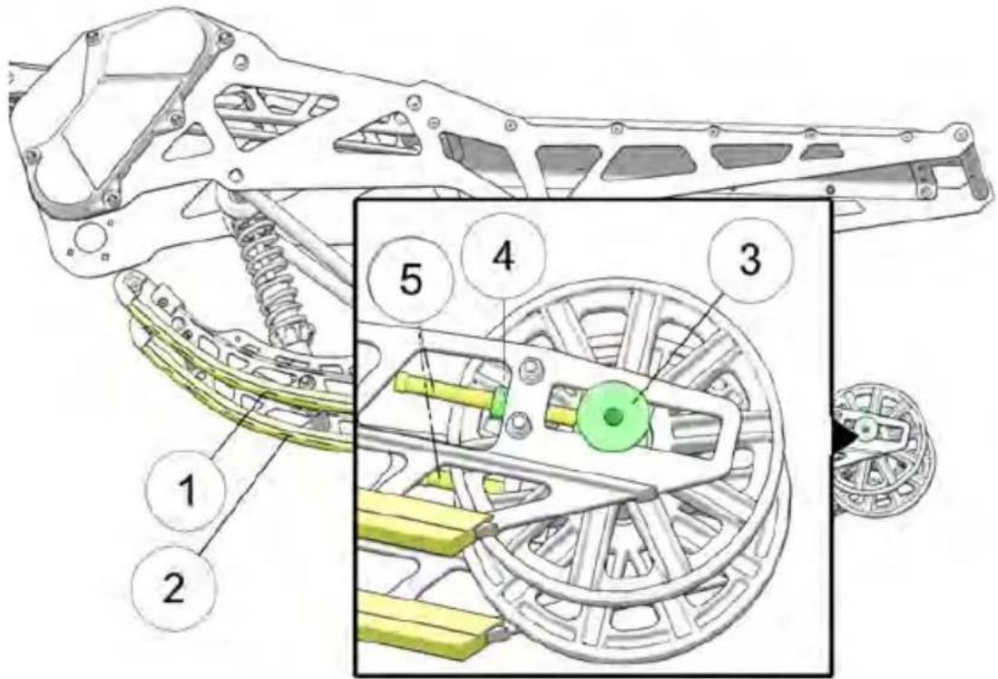
- If the track is running too far to the left, tighten the left side of the track by turning the tension adjustment bolt ⑤, on the left side of the bike, to the right (approximately one-half turn).
If the track is running too far to the right, tighten the right side of the track by turning the tension adjustment bolt ⑤, on the right side of the bike, to the right (approximately one-half turn).
NOTE
The amount you should turn the adjustment bolt on either side of the bike will depend on how far off center the track is running. Therefore it is suggested that you turn the bolt one-half turn at a time, checking the alignment between each half-turn adjustment to determine if additional adjustment is needed.
- Re-tighten the adjustment bolt's jam nut.
- Then re-torque the axle bolt.
TORQUE
Axle Bolt - 50 Nm (36.9 ft. lbs)
- Ensure the bike is still secure and the track is still off the ground. Then allow the bike to idle in gear for several revolutions which allows the track alignment adjustments to take full effect.
- Observe the running track for several additional revolutions before turning the engine off. When aligned properly, the track should appear to run straight and centered on the suspension rails.
- With the track stopped and the engine off, measure the horizontal distance ⑪ between the rail slide (i.e. hifax) and the track edge on both sides of the bike.
If the distance between the hifax and track edge is approximately the same on both sides of the bike, and the track appears to run centered on the rails, the track is properly aligned
If the distance between the hifax and track edge is NOT the same on both sides of the bike, and the track does NOT appear to run centered on the rails, repeat the steps above until your track is properly aligned. - Track Alignment adjustments will change the track's tension. After completing track alignment, it is best to measure track tension and adjust if necessary (see Track Tension section: page 66)
TRACK TENSION
Proper track tension adjustment is critical for proper snow bike handling. Always maintain proper track alignment and tension. Each track is slightly unique and will break in a bit differently depending on how and where you ride. If the track starts to skip on the drivers, this is a sign the track is too loose. If the rail sliders (i.e. hifax) is wearing quickly, the track tension may be too tight.
NOTE
Before measuring and adjusting track tension, ensure the track is properly aligned. For more information on track alignment, see the Track Alignment section beginning on page 63.
MEASURING TRACK TENSION

| TRACK TENSION DATA | |||
| SUSPENSION | PROPER SLACK MEASURE-MENT | APPLIED WEIGHT | MEASURE-MENT LOCATION - 8 |
| All Model Types 3/4" to 1" 10 lbs 10" | to 15" in front | of the rear axle | |
To measure track tension:
- Using an appropriate hoist or stand, safely lift and support the rear of the snow bike off the ground.
- Place the recommended weight ⑥ or downward pressure on the track at the measurement location ⑧ specified (see table).
- At the measurement location ⑧, measure the vertical slack or space ⑨ between the bottom of the hifax ① (i.e. rail slider) and the wear surface of the track clip ⑦. This is the slack measurement ⑨.
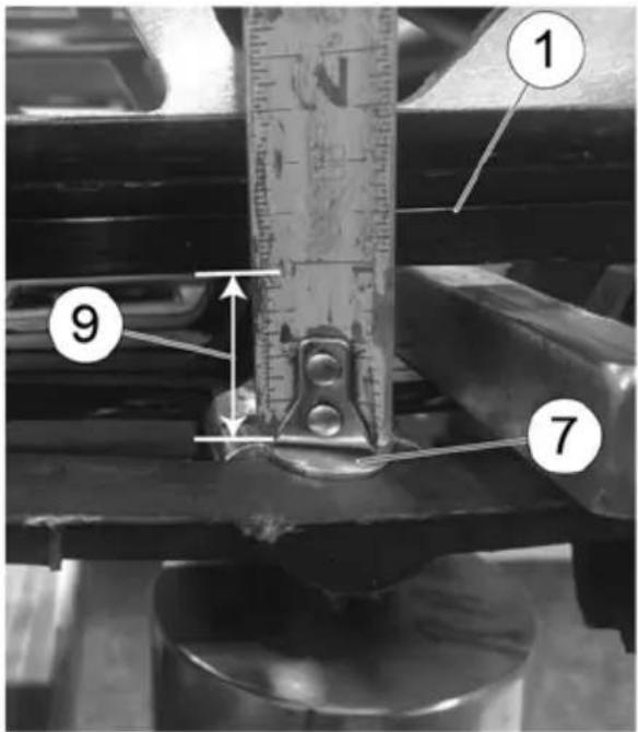
- If the track is properly tensioned, the slack measurement ⑨ should be between 3/4" to 1" (as shown in the table).
If the slack measurement ⑨ is less or greater than the proper slack measurement (3/4" to 1"), the track tension should be adjusted (see the following section, Adjusting Track Tension).
ADJUSTING TRACK TENSION
Measure track tension to be sure adjustment is needed.
NOTE
If the track starts to skip on the drivers, the track is too loose and will need to be adjusted. Occasionally this will happen after a new track has been run.
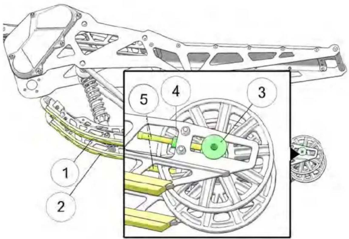
- With the rear of the bike off the ground and properly supported by a stand, loosen the axle bolt ③ on the track tensioning block.
-
Loosen the adjustment bolt's jam nut ④.
-
Then tighten or loosen the tension adjustment bolt ⑤, a half-turn at a time on both the right and left side of the bike. Turn the adjustment bolts the same amount on both sides of the track to tension the track evenly and keep the track aligned (track alignment should be performed before measuring and adjusting track tension).
Turning the adjustment bolts ⑤ on each side of the bike to the right will push the rear axle ③ back and tighten track tension.
Turning the adjustment bolts ⑤ on each side of the bike to the left will allow the rear axle ③ to move forward toward the front of the bike putting less tension on the track.
- Re-tighten the adjustment bolt's jam nut.
- Torque the axle bolt once again.
TORQUE
Axle Bolt - 50 Nm (36.9 ft. lbs)
- With the bike still secure and the track off the ground, rotate the track several times by hand or by running the engine in gear for several seconds. Then stop or turn the bike off. (It takes several track revolutions for track adjustment to take effect.)
- Measure the track tension again (see Measuring Track Tension).
If the slack measurement ⑨ is within the proper slack measurement range, your track tension is set properly.
If the tension is still too loose or too tight, repeat the steps above until your track tension is set properly.
- Once the track tension is set, check to ensure the track is still properly aligned. To check and adjust track alignment, see the Track Alignment section.
SKI MAINTENANCE
Timbersled recommends periodically inspecting your ski for damage.
- Check the ski bolt to make sure it is tight. Torque to specification.
TORQUE
45 Nm (33 ft. lbs)

WARNING
Failure to torque fasteners as directed will adversely affect the steering system and may lead to severe injury or death.
- Inspect for cuts or peeled up plastic that will cause the ski to handle poorly.
- Inspect for bent, broken, or worn-out ski skags.
- Inspect the ski saddle for bends that may make the ski crooked.
- Inspect the ski rubber to make sure it is not smashed or worn out.
NOTE
Timbersled highly recommended that you DO NOT tie your bike against the front of the ski. This can permanently bend the plastic ski causing your bike to handle poorly.
SKI SKAGS

WARNING
Worn skis and/or skags will adversely affect handling. Loss of vehicle control may result, causing serious injury or death. See your dealer's studding chart for recommended skags.
Check skags before each use of the snow bike to ensure positive steering characteristics. Skags must be replaced when worn to half their original diameter.
TIP
Carbide skags must be replaced if any abnormal wear or chipping is found.
SKAG REPLACEMENT
- Raise and support the front of the snow bike so the ski is approximately 6 inches (15.2 cm) from the ground.
- Remove the attaching nuts ① and pry the skag ② downward.
- Remove the front end of the skag.
- Remove the rear end of the skag.
- Reverse the steps to install a skag.

RAIL SLIDE WEAR
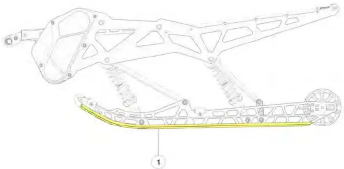
natural_image
Technical line drawing of a mechanical assembly with labeled component 1 (no text or symbols beyond label)Timbersled rail slides ① run along the bottom of the rail to prevent track wear. Both the left and right rail slide should be inspected periodically and replaced when necessary.
For ease of inspection, all Timbersled rail slides have a wear limit indicator groove ② to indicate the minimum permissible slide thickness ③. Replace the rail slides if they are worn to the top of the groove at any point along their length. Failure to do so may result in permanent damage to the track or rails.
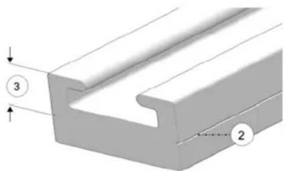
SPINDLE MAINTENANCE
The spindle does not require any maintenance. It is designed to bend if it comes in contact with a rock or stump during operation. Timbersled recommends thoroughly inspecting the assembly for bends or cracks before you ride.
FALL TUNE-UP
For maximum performance, your Timbersled dealer can perform a fall service tune-up. Their experienced and trained service technicians will keep your snow bike in peak operating condition.
MATTE CLEAR COAT CLEANING (IF EQUIPPED)
Matte finish products are prone to trapping dirt, oils and other contaminants. Timbersled recommends cleaning with warm water and a mild dish detergent. Use a soft sponge to gently rub the surface and rinse with clean warm water. For stubborn stains such as grease or oil, use a citrus based cleaner (3M Citrus Base Cleaner recommended). Spray onto the area to be cleaned and rub with a soft sponge. Allow to sit for a couple of minutes and wash away with clean warm water. Repeat as necessary to clean the surface.
NOTICE
Never use a polishing/buffing wax or any sponge that has an abrasive surface. These products will buff the matte surface of the finish resulting in a glossy finish. It is not recommended that you clean matte finishes with a pressure washer as this will further imbed contaminants into the clear coat and possibly damage the labels.
EXTENDED STORAGE
Off-season or extended storage of your snow bike requires preventive measures to aid against deterioration and to prolong the useful life of many components.
CLEANING AND PRESERVATION
Proper storage starts with cleaning, washing, and waxing the cowling, side panels, chassis, and plastic parts. Wipe down remaining surfaces with a damp cloth. Clean and touch up with paint any rusted or previously painted surfaces. Be sure that corrosive salt and acids are removed from surfaces before beginning preservation with waxes and rust inhibitors (grease, oil or paint).
The snow bike should be stored in a dry garage or shed, out of direct sunlight, and covered with a fabric snow bike cover. Plastic tarp may cause condensation to form and damage snow bike components.
TRACK AND SUSPENSION
Moderate track tension should be maintained during summer storage. The snow bike should be supported off the ground to allow the track to hang freely.
Whenever the snow bike is transported:
- Be sure the fuel cap and oil cap are installed correctly.
- Tie the snow bike to the transporting unit securely using suitable straps.
- Remove the ignition key (if equipped) to prevent loss.
NOTE
Use of a cover is recommended when transporting your vehicle on an open trailer.
SPECIFICATION
RIOT 120
| DIMENSIONS | |
| Estimated Dry Weight - Front 16 lbs (7.25 kg) | |
| Estimated Dry Weight - Rear 106 lbs (48 kg) | |
| Overall Length - pivot to bumper 65 in (165.1 cm) | |
| ENGINE AND DRIVETRAIN | |
| Disc Brake Type Wilwood Hydraulic Dual Piston | |
| Track Drive Sprocket 6 tooth / 2.86 pitch | |
| Drive Shaft Sprocket 17 tooth - 15t spline | |
| Upper Chain Case Sprocket 18 tooth -15t spline | |
| Lower Chain Case Sprocket 17 tooth - 15t spline | |
| Drive Chain EK520 SRX2 70 Link (master link) | |
| Chain Case Chain EK520 SRX2 52 Link (continuous) | |
| Chain Slider Standard | |
| SUSPENSION | |
| Rear Suspension RIOT Long Arm | |
| Front Track Shock FOX ZERO Pro® (IFP) | |
| Rear Track Shock FOX ZERO Pro® (IFP) | |
| Rear Travel - Fixed Fit Kit 13.0 in (33.0 cm) | |
| Rear Travel - TSS Fit Kit | 21.0 in (53.0 cm) |
| Ski Type | Traverse |
| Skag Type | Deuce Bar Center Skag |
| Track Width/Length/Height | 11.5" x 120" x 2.5" Traverse |
| FEATURES | |
| Fuel Storage | Accessory (3.5 gal / 13.2 L) |
| Fuel Storage Strap | Accessory |
| Storage | Accessory |
| Install Kits | Fixed Strut/Suspension Strut |
RIOT 120 LE
| DIMENSIONS | |
| Estimated Dry Weight - Front (lbs./kg.) 16 lbs (7.25 kg) | |
| Estimated Dry Weight - Rear (lbs./kg.) 110 lbs (49.9 kg) | |
| Overall Length - pivot to bumper (in./cm.) 65 in (165.1 cm) | |
| ENGINE AND DRIVETRAIN | |
| Disc Brake Type Wilwood Hydraulic Dual Piston | |
| Track Drive Sprocket 6 tooth / 2.86 pitch | |
| Drive Shaft Sprocket 17 tooth - 15t spline | |
| Upper Chain Case Sprocket 18 tooth - 15t spline | |
| Lower Chain Case Sprocket 17 tooth - 15t spline | |
| Drive Chain EK520 SRX2 70 Link (master link) | |
| Chain Case Chain EK520 SRX2 52 Link (continuous) | |
| Chain Slider Standard | |
| SUSPENSION | |
| Rear Suspension RIOT Long Arm | |
| Front Track Shock FOX ZERO QS3 ® | |
| Rear Track Shock FOX ZERO QS3 ® | |
| Rear Travel - Fixed Fit Kit 13.0 in (33.0 cm) | |
| Rear Travel - TSS Fit Kit 21.0 in (53.0 cm) | |
| Ski Type | Traverse |
| Skag Type | Deuce Bar Center Skag |
| Track Width/Length/Height | 11.5" x 120" x 2.5" Traverse |
| FEATURES | |
| Fuel Storage | Accessory (3.5 gal / 13.2 L) |
| Fuel Storage Strap | Accessory |
| Storage | Accessory |
| Install Kits | Fixed Strut/Suspension Strut |
ARO SX 120
| DIMENSIONS | |
| Estimated Dry Weight - Front 16.5 lbs (7.4 kg) | |
| Estimated Dry Weight - Rear 120 lbs (54.43 kg) | |
| Overall Length - pivot to bumper 63.0 in (160.0 cm) | |
| ENGINE AND DRIVETRAIN | |
| Disc Brake Type Wilwood Hydraulic Dual Piston | |
| Track Drive Sprocket 6 tooth / 2.86 pitch | |
| Drive Shaft Sprocket 17 tooth - 15t spline | |
| Upper Chain Case Sprocket 18 tooth - 15t spline | |
| Lower Chain Case Sprocket 17 tooth - 15t spline | |
| Drive Chain EK520 SRX2 70 Link (master link) | |
| Chain Case Chain EK520 SRX2 52 Link (continuous) | |
| Chain Slider Standard | |
| SUSPENSION | |
| Rear Suspension ARO Long Travel | |
| Front Track Shock FOX 1.5 ZERO LSC-R | |
| Rear Track Shock FOX 1.5 ZERO LSC-R | |
| Rear Travel - Fixed Fit Kit 12.0 in (30.5 cm) | |
| Rear Travel - TSS Fit Kit 20.0 in (50.8 cm) | |
| Ski Type | Traverse |
| Skag Type | Traverse Hardened |
| Track Width/Length/Height | 11.5" x 120" x 2.5" Traverse |
| FEATURES | |
| Fuel Storage | Accessory (3.5 gal / 13.2 L) |
| Fuel Storage Strap | Accessory |
| Storage | Accessory |
| Install Kits | Fixed Strut/Suspension Strut |
ARO 129
| DIMENSIONS | |
| Estimated Dry Weight - Front 16 lbs (7.25 kg) | |
| Estimated Dry Weight - Rear 117.0 lbs (53.1 kg) | |
| Overall Length - pivot to bumper 65.5 in (166.37 cm) | |
| ENGINE AND DRIVETRAIN | |
| Disc Brake Type Wilwood Hydraulic Dual Piston | |
| Track Drive Sprocket 6 tooth / 2.86 pitch | |
| Drive Shaft Sprocket 17 tooth - 15t spline | |
| Upper Chain Case Sprocket 18 tooth - 15t spline | |
| Lower Chain Case Sprocket 17 tooth - 15t spline | |
| Drive Chain EK520 SRX2 70 Link (master link) | |
| Chain Case Chain EK520 SRX2 52 Link (continuous) | |
| Chain Slider Standard | |
| SUSPENSION | |
| Rear Suspension ARO Long Travel | |
| Front Track Shock FOX ZERO Pro® (IFP) | |
| Rear Track Shock FOX ZERO Pro® (IFP) | |
| Rear Travel - Fixed Fit Kit 12.0 in (30.5 cm) | |
| Rear Travel - TSS Fit Kit 20.0 in (50.8 cm) | |
| Ski Type | Traverse |
| Skag Type | Traverse Hardened |
| Track Width/Length/Height | 11.5" x 129" x 2.5" Traverse |
| FEATURES | |
| Fuel Storage | Accessory (3.5 gal / 13.2 L) |
| Fuel Storage Strap | Accessory |
| Storage | Accessory |
| Install Kits | Fixed Strut/Suspension Strut |
ARO 129 LE
| DIMENSIONS | |
| Estimated Dry Weight - Front 16 lbs (7.2 kg) | |
| Estimated Dry Weight - Rear 117.4 lbs (53.25 kg) | |
| Overall Length - pivot to bumper 65.5 in (166.37 cm) | |
| ENGINE AND DRIVETRAIN | |
| Disc Brake Type Wilwood Hydraulic Dual Piston | |
| Track Drive Sprocket 6 tooth / 2.86 pitch | |
| Drive Shaft Sprocket 17 tooth - 15t spline | |
| Upper Chain Case Sprocket 18 tooth - 15t spline | |
| Lower Chain Case Sprocket 17 tooth - 15t spline | |
| Drive Chain EK520 SRX2 70 Link (master link) | |
| Chain Case Chain EK520 SRX2 52 Link (continuous) | |
| Chain Slider Standard | |
| SUSPENSION | |
| Rear Suspension ARO Long Travel | |
| Front Track Shock FOX ZERO QS3 ® | |
| Rear Track Shock FOX ZERO QS3 ® | |
| Rear Travel - Fixed Fit Kit 12.0 in (30.5 cm) | |
| Rear Travel - TSS Fit Kit 20.0 in (50.8 cm) | |
| Ski Type | Traverse |
| Skag Type | Traverse Hardened |
| Track Width/Length/Height | 11.5" x 129" x 2.5" Traverse |
| FEATURES | |
| Fuel Storage | Accessory (3.5 gal / 13.2 L) |
| Fuel Storage Strap | Accessory |
| Storage | Accessory |
| Install Kits | Fixed Strut/Suspension Strut |
ARO 129 LE 3"
| DIMENSIONS | |
| Estimated Dry Weight - Front 16 lbs (7.2 kg) | |
| Estimated Dry Weight - Rear 119 lbs (53.98 kg) | |
| Overall Length - pivot to bumper 67.5 in (171.5 cm) | |
| ENGINE AND DRIVETRAIN | |
| Disc Brake Type Wilwood Hydraulic Dual Piston | |
| Track Drive Sprocket 6 tooth / 3.0 pitch | |
| Drive Shaft Sprocket 17 tooth - 15t spline | |
| Upper Chain Case Sprocket 17 tooth - 15t spline | |
| Lower Chain Case Sprocket 18 tooth - 15t spline | |
| Drive Chain EK520 SRX2 70 Link (master link) | |
| Chain Case Chain EK520 SRX2 52 Link (continuous) | |
| Chain Slider Standard | |
| SUSPENSION | |
| Rear Suspension ARO Long Travel | |
| Front Track Shock FOX ZERO QS3 ® | |
| Rear Track Shock FOX ZERO QS3 ® | |
| Rear Travel - Fixed Fit Kit 12.0 in (30.5 cm) | |
| Rear Travel - TSS Fit Kit 20.0 in (50.8 cm) | |
| Ski Type | Traverse |
| Skag Type | Traverse Hardened |
| Track Width/Length/Height | 11.5" x 129" x 3" Traverse |
| FEATURES | |
| Fuel Storage | Accessory (3.5 gal / 13.2 L) |
| Fuel Storage Strap | Accessory |
| Storage | Accessory |
| Install Kits | Fixed Strut/Suspension Strut |
ARO 137 LE
| DIMENSIONS | |
| Estimated Dry Weight - Front 16 lbs (7.25 kg) | |
| Estimated Dry Weight - Rear 121 lbs (54.9 kg) | |
| Overall Length - pivot to bumper 72 in (182.9 cm) | |
| ENGINE AND DRIVETRAIN | |
| Disc Brake Type Wilwood Hydraulic Dual Piston | |
| Track Drive Sprocket 6 tooth / 2.86 pitch | |
| Drive Shaft Sprocket 17 tooth - 15t spline | |
| Upper Chain Case Sprocket 18 tooth - 15t spline | |
| Lower Chain Case Sprocket 17 tooth - 15t spline | |
| Drive Chain EK520 SRX2 70 Link (master link) | |
| Chain Case Chain EK520 SRX2 52 Link (continuous) | |
| Chain Slider Standard | |
| SUSPENSION | |
| Rear Suspension ARO Long Travel | |
| Front Track Shock FOX ZERO QS3 ® | |
| Rear Track Shock FOX ZERO QS3 ® | |
| Rear Travel - Fixed Fit Kit 12.0 in (30.5 cm) | |
| Rear Travel - TSS Fit Kit 20.0 in (50.8 cm) | |
| Ski Type | Traverse |
| Skag Type | Traverse Hardened |
| Track Width/Length/Height | 11.5" x 137" x 2.5" Traverse |
| FEATURES | |
| Fuel Storage | Accessory (3.5 gal / 13.2 L) |
| Fuel Storage Strap | Accessory |
| Storage | Accessory |
| Install Kits | Fixed Strut/Suspension Strut |
TORQUE TABLES
RAILS AND TRACK

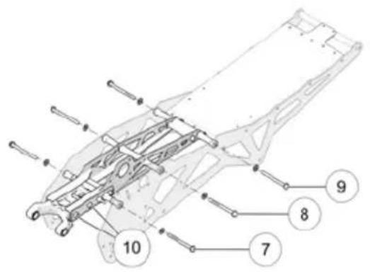
| Torque Torque | |||
| 1 | 60 Nm with Red Loc Tite 263 | 6 | 60 Nm with Blue Loc Tite 243 |
| 2 | 60 Nm with Red Loc Tite 263 | 7 | 60 Nm with Red Loc Tite 263 |
| 3 | 60 Nm with Red Loc Tite 263 (Tighten from Nut Side) | 8 | 60 Nm with Red Loc Tite 263 |
| 4 | 60 Nm with Red Loc Tite 263 | 9 | 60 Nm with Red Loc Tite 263 |
| 5 | 60 Nm (Tighten from Nut Side) | 10 | 50 Nm |
SPINDLE AND SKI

natural_image
Mechanical assembly diagram showing a bracket with bolts and a numbered component (no text or symbols present)
| Torque Torque | |||
| 1 | 50 Nm (Tighten from Nut Side) | 2 | 45 Nm |
| 3 | 18 Nm | ||
BRAKES

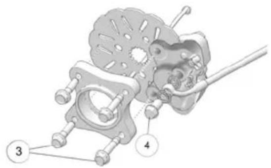
| Torque Torque | |||
| 1 | 60 Nm | 3 | 25 Nm |
| 2 | 11 Nm | 4 | 20 Nm |
DRIVE CHAIN ASSEMBLY


natural_image
Diagram of a mechanical or robotic arm with labeled joints and connecting rods (no text or symbols present)| Torque Torque | |||
| 1 | 25 Nm | 3 | 8 Nm |
| 2 | 60 Nm with Red 263 Loc Tite | ||
WARRANTY
TIMBERSLED CONVERSION SYSTEMS LIMITED WARRANTY
POLARIS Sales Inc., 2100 Highway 55, Medina, MN 55340 (POLARIS) gives a 12 MONTH LIMITED WARRANTY on all components of your TIMBERSLED Conversion System against defects in material or workmanship. This warranty covers parts and dealer labor charges for repair or replacement of defective parts and begins on the date of purchase by the original retail purchaser. This warranty is transferable to another owner during the warranty period through a TIMBERSLED dealer, but any such transfer will not extend the original term of the warranty. The duration of this warranty may vary by international region based upon local laws and regulations.
See your dealer for details and separate terms and conditions for any promotional warranties.
REGISTRATION
At the time of sale, the Warranty Registration Form must be completed by your dealer and submitted to TIMBERSLED within ten days of purchase. Upon receipt of this registration, TIMBERSLED will record the registration for warranty. No verification of registration will be sent to the purchaser as the copy of the Warranty Registration Form will be your proof of warranty coverage. If you have not signed the original registration and received the customer copy, please contact your dealer immediately. NO WARRANTY COVERAGE WILL BE ALLOWED UNLESS YOUR CONVERSION SYSTEM IS REGISTERED WITH TIMBERSLED.
WARRANTY COVERAGE AND EXCLUSIONS: LIMITATIONS OF WARRANTIES AND REMEDIES
This TIMBERSLED limited warranty excludes any failures that are not caused by a defect in material or workmanship. THIS WARRANTY DOES NOT COVER CLAIMS OF DEFECTIVE DESIGN. This warranty also does not cover damage caused due to incorrect installation, acts of God, accidental damage, normal wear and tear, abuse or improper handling. This warranty also does not cover any Conversion System, component, or part that has been altered structurally, modified, neglected, improperly maintained, used for racing, competition, or for purposes other than for which it was designed.
This warranty also excludes failures resulting from improper lubrication; surface imperfections caused by external stress, heat, cold or contamination; operator error or abuse; improper component alignment, tension, adjustment; improper maintenance; modified components; use of aftermarket components; unauthorized repairs; repairs made after the warranty period expires or by an unauthorized repair center; use of the product in competition or for commercial purposes. Warranty will not apply to any product which has been damaged by abuse, accident, fire or any other casualty not determined a defect of materials or workmanship.
This warranty excludes coverage for consumable components, general wear items, or any parts exposed to friction surfaces, stresses, environmental conditions and/or contamination for which they were not designed or not intended, including but not limited to the following items:
| Skis | Ski Wear Rods |
| Tracks | Slide Rails |
| Suspension Components | Finished and Unfinished Surfaces |
| Brake Components | Chains |
| Idler Wheels | Hydraulic Components |
This warranty provides no coverage for personal loss or expense, including mileage, transportation costs, hotels, meals, shipping or handling fees, product pick-up or delivery, replacement rentals, loss of product use, loss of profits, or loss of vacation or personal time.
THE EXCLUSIVE REMEDY FOR BREACH OF THIS WARRANTY SHALL BE, AT POLARIS' OPTION, REPAIR OR REPLACEMENT OF ANY DEFECTIVE MATERIALS, COMPONENTS, OR PRODUCTS. THE REMEDIES SET FORTH IN THIS WARRANTY ARE THE ONLY REMEDIES AVAILABLE TO ANY PERSON FOR BREACH OF THIS WARRANTY. POLARIS SHALL HAVE NO LIABILITY TO ANY PERSON FOR INCIDENTAL, CONSEQUENTIAL OR SPECIAL DAMAGES OF ANY DESCRIPTION, WHETHER ARISING OUT OF EXPRESS OR IMPLIED WARRANTY OR ANY OTHER CONTRACT, NEGLIGENCE, OR OTHER TORT OR OTHERWISE. THIS EXCLUSION OF CONSEQUENTIAL, INCIDENTAL AND SPECIAL DAMAGES IS INDEPENDENT FROM AND SHALL SURVIVE ANY FINDING THAT THE EXCLUSIVE REMEDY FAILED OF ITS ESSENTIAL PURPOSE.
THE IMPLIED WARRANTY OF FITNESS FOR A PARTICULAR PURPOSE IS EXCLUDED FROM THIS LIMITED WARRANTY. ALL OTHER IMPLIED WARRANTIES (INCLUDING BUT NOT LIMITED TO THE IMPLIED WARRANTY OF MERCHANTABILITY) ARE LIMITED IN DURATION TO THE ABOVE 12 MONTH WARRANTY PERIOD. TIMBERSLED DISCLAIMS ALL EXPRESS WARRANTIES NOT STATED IN THIS WARRANTY. SOME STATES DO NOT PERMIT THE EXCLUSION OR LIMITATION OF INCIDENTAL OR CONSEQUENTIAL DAMAGES OR ALLOW LIMITATIONS ON THE DURATION OF IMPLIED WARRANTIES, SO THE ABOVE LIMITATIONS MAY NOT APPLY TO YOU IF INCONSISTENT WITH CONTROLLING STATE LAW.
HOW TO OBTAIN WARRANTY SERVICE
If your Conversion System requires warranty service, you must take it to a TIMBERSLED Servicing Dealer. When requesting warranty service you must present your copy of the Warranty Registration to the dealer. (THE COST OF TRANSPORTATION TO AND FROM THE DEALER IS YOUR RESPONSIBILITY). TIMBERSLED suggests that you use your original selling dealer; however, you may use any TIMBERSLED Servicing Dealer to perform warranty service.
In the Country where your product was purchased:
Warranty or Service Bulletin repairs must be done by an authorized TIMBERSLED dealer. If you move or are traveling within the country where your product was purchased, Warranty and Service Bulletin repairs may be requested from any authorized TIMBERSLED dealer that sells the same line as your product.
Outside the Country where your product was purchased:
If you are traveling temporarily outside the country where your product was purchased, you should take your product to an authorized TIMBERSLED dealer. You must show the dealer photo identification from the country of the selling dealer's authorized location as proof of residence. Upon residence verification, the servicing dealer will be authorized to perform the warranty repair.
If you move:
If you move to another country, be sure to contact TIMBERSLED Customer Assistance and the customs department of the destination country before you move. Product importation rules vary considerably from country to country. You may be required to present documentation of your move to TIMBERSLED in order to continue your warranty coverage. You may also be required to obtain documentation from TIMBERSLED in order to register your product in your new country. You should warranty register your product at a local TIMBERSLED dealer in your new country immediately after you move to continue your warranty coverage and to ensure that you receive information and notices regarding your Conversion System.
If you purchase from a private party:
If you purchase a TIMBERSLED product from a private party, to be kept and used outside of the country in which the product was originally purchased, all warranty coverage will be denied. You must nonetheless register your product under your name and address with a local TIMBERSLED dealer in your country to ensure that you receive safety information and notices regarding your product.
EXPORTED PRODUCTS
EXCEPT WHERE SPECIFICALLY REQUIRED BY LAW, THERE IS NO WARRANTY OR SERVICE BULLETIN COVERAGE ON THIS PRODUCT IF IT IS SOLD OUTSIDE THE COUNTRY OF THE SELLING DEALER'S AUTHORIZED LOCATION. This policy does not apply to products that have received authorization for export from TIMBERSLED. Dealers may not give authorization for export. You should consult an authorized dealer to determine this product's warranty or service coverage if you have any questions. This policy does not apply to products registered to government officials or military personnel on assignment outside the country of the selling dealer's authorized location. This policy does not apply to Safety Bulletins.
NOTICE
If your product is registered outside of the country where it was purchased and you have not followed the procedure set above, your product will no longer be eligible for warranty or service bulletin coverage of any kind, other than safety bulletins. Products registered to Government officials or military personnel on assignment outside of the country where the product was purchased will continue to be covered by the Limited Warranty.
Please work with your dealer to resolve any warranty issues. Should your dealer require any additional assistance, they will contact the appropriate TIMBERSLED department.
This warranty gives you specific legal rights, and you may also have other rights which vary from state to state or in different countries. If any of the above terms are void because of federal, state, local law, all other warranty terms will remain in effect.
For questions call TIMBERSLED Customer Assistance:
United States & Canada: 1-800-POLARIS (1-800-765-2747)
French: 1–800–268–6334
MAINTENANCE LOG
MAINTENANCE LOG
Present this section of your manual to your dealer each time your snowmobile is serviced. This will provide you and future owners with an accurate log of maintenance and services performed on the snowmobile.
| DATE | MILES (KM) | TECHNICIAN | SERVICE PERFORMED / COMMENTS |
| 150 mi. (240 km) | |||
| 500 mi (800 km) | |||
| 1000 mi (1600 km) | |||
| 2000 mi (3200 km) | |||
| DATE | HOURS TECHNICIAN | SERVICE PERFORMED / COMMENTS |
, Inspection....Driving 61Hilly Terrain....
Driving on Slippery Surfaces ..... 20
Driving Responsibly ....
A
Accessories 29
E
Accessory Warning 25
ARO SX 120 Specifications ..... 77Environment Preservation ..... 7
Avalanche Awareness .... Excessive Speed.
Avalanche Danger Scale. 1B Exhaust System
Avalanches 13
F
B
Before Starting the Engine. 43 Brake Fluid.
Bleeding Hydraulic Brake FOX 1.5 Zero LSC-R Shocks ..... 37
System ...... FOX.QS35shocks
Brake Inspection....From54Track Shock Factory
Brake Lever Travel....Spring Settings.
Brake pads....Fuel.Prefix (Initial Fill)....4
Brakes .... Fuel Recommendation.... 4
Brake Fluid. . . . . . . . . . . . . . . . . . . . . . . . . . . . . . . . . . . . . . . . . . . . . . . . . . . . . . . . . . . . . . . . Fuel. Storage.
Components....54
Inspection 54
Lever Travel 54
System Bleeding 55
Break-In Period....Host Btke.
H
C
Cargo Storage ..... IFP. Stocks
Chain Case Chain ....Inadequate Snow Conditions ....20
Adjustment. . . . . . . . . . . . . . . . . . . . . . . . . . . . . . . . . . . . . . . . . . . . . . . . . . . . . . . . . . . . . . . . . . . . . . . . . . inspection, Pre-Ride.
Chain Lubrication ....... Installation
Cleaning for Matte Finishes ..... 73
Cold Weather Drive-Away 21
Component Location 27
|
D
Disabled Operators.... Matte Finish Cleaning.... 7
Drive Chain .... Mountainous Terrain Riding .... 13
Drive Chain Tension 56
Driver Awareness 12
Driving Downhill 21
M
Maintenance Log.
Maintenance Recommendations.....9
Maneuverability.
Matte Finish Cleaning....7
Mountai64us Terrain Riding ..... 13
0
Suspension Quick Setup Guide . . . 31-
33, 35-38
Oil Recommendations 45
Operating in Deep Snow 20
Operator Safety. 9-10
T
P
Temperature Charts 23
Tools.
Towing Warning ....
Periodic Maintenance Table ..... 50-
Track
Pre-Ride Suspension Inspection . . . 42
Inspection ....
Proper Use Warning.
Eubrication ....
Tension ....
R
Track Care, Storage. 73
Track Inspection....44....
Track Lug Separation, Deep
Lugs
Rail Ice Scratchers.
Track Maintenance 63, 66
Rail Slide Wear
Track Warm-Up.
Rear Track Shock Spring
Transporting the Snow Bike ..... 74
Settings
TSS Shock Tuning .... 3
Recommended Maintenance ..... 49
Tune-Up
Rider Capacity ....
10-11
Riding Apparel ....
... 10
Riding Position.
RIOT 120 LE Specifications ..... 76
RIOT 120 Specifications ..... 75
V
Vehicle Identification Numbers ..... 8
S
W
Safety Symbols 4
Signal Words ....Warning Symbols
Skag Replacement ....Warranty.
Ski Maintenance....70 Ski Skags....70 Windchill Charts
Slide Rail and Track Cooling ..... 46
Snow Bike System Break-In. 45
Snow Conditions 20
Spindle bolts. 42
Spindle Maintenance....72
Steering System Inspection ..... 43
Storage Procedures, Seasonal ..... 73
Storage, Daily 48
Survival Preparation....11
Suspension Inspection, Pre-Ride 42
Suspension Maintenance ..... 53
Suspension mounting bolts. 42

For your nearest Polaris dealer,
call 1-800-POLARIS (765-2747)
or visit www.polaris.com
Polaris Industries Inc.
2100 Highway 55
Medina, MN 55340
Part No. 9929951 Rev 01
Printed in USA



- WARNING
- Owner's Manual
- DANGER
- CAUTION
- IMPORTANT
- NOTICE
- INTRODUCTION
- IMPORTANT NOTES FOR OWNERS AND DRIVERS
- PRESERVATION OF THE ENVIRONMENT
- INSTALLATION
- VEHICLE IDENTIFICATION NUMBERS
- SAFETY
- OPERATOR SAFETY
- HOST BIKE
- STAY CLEAR OF TRACK
- RIDING POSITION
- RIDER CAPACITY
- RIDING APPAREL
- HELMET
- EYE PROTECTION
- CLOTHING
- SURVIVAL PREPARATION
- EXCESSIVE SPEED
- DRIVER AWARENESS
- DISABLED OPERATORS
- MOUNTAINOUS TERRAIN RIDING
- GET THE SAFETY GEAR
- GET TO KNOW YOUR SAFETY GEAR
- GET THE PICTURE
- NOTE
- GET OUT OF HARM'S WAY
- GET TO KNOW YOUR SNOW BIKE
- Do not ride in mountainous terrain until you are comfortable riding and controlling your snow bike in deep snow.
- GET THE FORECAST
- GET AVALANCHE SAFETY TRAINING
- AVALANCHE AWARENESS
- North American Public Avalanche Danger Scale
- ICE AND SNOW BUILD-UP
- DRIVING ON SLIPPERY SURFACES
- INADEQUATE SNOW CONDITIONS
- DRIVING DOWNHILL
- DRIVING IN HILLY TERRAIN
- MANEUVERABILITY
- DRIVING RESPONSIBLY
- WINDCHILL/TEMPERATURE CHARTS
- PROPER USE WARNING
- TOWING WARNING
- ACCESSORY WARNING WARNING
- FEATURES
- COMPONENT LOCATIONS
- CHAIN CASE COMPONENTS
- TOOLS
- CARGO STORAGE
- RAIL ICE SCRATCHERS
- ACCESSORIES
- THE PERFECT FIT
- SUSPENSION QUICK SETUP GUIDE
- TIMBERSLED ARO SUSPENSION QUICK SETUP
- TIMBERSLED RIOT SUSPENSION QUICK SETUP
- Step 1: Ride your Timbersled RIOT snow bike.
- Step 2: Adjust the spring preload to tune vehicle balance.
- Step 3: Adjust shock clickers (if equipped) for ride quality.
- Soft: Turn the clicker all the way to it's farthest counterclockwise position to achieve a softer or more plush ride with the least amount of compression damping.
- Medium: Turn the clicker one click clockwise from its soft position to achieve a intermediate ride (between plush and stiff) with a medium amount of compression damping.
- Stiff: Turn the clicker two clicks clockwise from it's soft position for a stiffer ride with the highest amount of compression damping.
- TIP
- FRONT TRACK SHOCK SPRING SETTINGS
- REAR TRACK SHOCK SPRING SETTINGS
- TSS SHOCK TUNING
- PRE-RIDE INSPECTION
- PRE-RIDE CHECKLIST
- PRE-RIDE SUSPENSION INSPECTION
- BEFORE STARTING THE ENGINE
- READ AND UNDERSTAND YOUR OWNER'S MANUAL
- STEERING SYSTEM
- BRAKES
- BRAKE LEVER TRAVEL
- LEVER FEEL
- TRACK
- OPERATION
- BREAK-IN PERIOD
- TRACK WARM-UP
- SLIDE RAIL AND TRACK COOLING
- FUEL STORAGE
- FUEL RECOMMENDATION
- DAILY STORAGE
- MAINTENANCE
- TIMBERSLED RECOMMENDED MAINTENANCE PROGRAM
- PERIODIC MAINTENANCE TABLE
- LUBRICATION
- CHAIN LUBRICATION
- TRACK LUBRICATION
- EXHAUST SYSTEM
- SUSPENSION
- SUSPENSION MAINTENANCE
- EXCESSIVE LEVER TRAVEL
- BRAKE FLUID
- TORQUE
- DRIVE SYSTEM
- DRIVE CHAIN TENSION
- MEASURING DRIVE CHAIN TENSION
- ADJUSTING DRIVE CHAIN TENSION
- CHAIN CASE CHAIN TENSION
- MEASURING CHAIN CASE CHAIN TENSION
- ADJUSTING CHAIN CASE CHAIN TENSION
- CHAIN INSPECTION
- TRACK ALIGNMMENT
- INSPECTING TRACK ALIGNMENT
- ADJUSTING TRACK ALIGNMENT
- TRACK TENSION
- MEASURING TRACK TENSION
- ADJUSTING TRACK TENSION
- Axle Bolt - 50 Nm (36.9 ft. lbs)
- SKI MAINTENANCE
- SKI SKAGS
- SKAG REPLACEMENT
- RAIL SLIDE WEAR
- SPINDLE MAINTENANCE
- FALL TUNE-UP
- MATTE CLEAR COAT CLEANING (IF EQUIPPED)
- EXTENDED STORAGE
- CLEANING AND PRESERVATION
- TRACK AND SUSPENSION
- SPECIFICATION
- RIOT 120
- TORQUE TABLES
- RAILS AND TRACK
- SPINDLE AND SKI
- WARRANTY
- TIMBERSLED CONVERSION SYSTEMS LIMITED WARRANTY
- REGISTRATION
- WARRANTY COVERAGE AND EXCLUSIONS: LIMITATIONS OF WARRANTIES AND REMEDIES
- HOW TO OBTAIN WARRANTY SERVICE
- EXPORTED PRODUCTS
- MAINTENANCE LOG
- A
- E
- F
- B
- H
- C
- |
- D
- M
- 0
- T
- P
- R
- V
- S
- W
Brand : Timbersled
Model : ARO 120 SX (2020)
Category : Snowmobile