Universal Motion - Door closer Dormakaba - Free user manual and instructions
Find the device manual for free Universal Motion Dormakaba in PDF.


| Product Type | Bottom Center Hung Self-Closing Patch Fitting |
| Brand | Dormakaba |
| Model | Universal Motion |
| Application | Pivoting glass doors for indoor or covered areas |
| Maximum Door Weight | 220 lbs (100 kg) |
| Maximum Door Width | ≤40" (1000 mm) |
| Maximum Door Height (Option 1) | ≤84" (2133 mm) |
| Maximum Door Height (Option 2) | ≤102" (2590 mm) |
| Glass Thickness Compatibility | 3/8" (10 mm) or 1/2" (12 mm) |
| Glass Type Required | Fully tempered monolithic glass (ASTM C 1036, C 1048) |
| Mounting System | Floor pivot plate with self-closing patch fitting |
| Hold Open Function | Yes, adjustable up to 90° in either direction |
| Closing Speed Adjustment | Sweep valve (140°-45°) and Latch valve (45°-close) |
| Torque Specification (Inserts) | 9 ft lbs (12 Nm) |
| Hex Key Size | 5 mm |
| Number of Screws (Patch Fitting) | 6 hex screws |
| Installation Personnel | Two persons required |
| Required Safety Gear | Protective clothing, gloves, goggles |
| Maintenance Interval | Inspect every 500,000 cycles; replace damaged parts immediately |
| Cleaning Method | Alcohol-based cleaner; avoid silicone or oil-based products |
| Replacement Parts | Use only original dormakaba parts |
| Disposal | Follow local, state, and national regulations |
Frequently Asked Questions - Universal Motion Dormakaba
User questions about Universal Motion Dormakaba
0 question about this device. Answer the ones you know or ask your own.
Ask a new question about this device
Download the instructions for your Door closer in PDF format for free! Find your manual Universal Motion - Dormakaba and take your electronic device back in hand. On this page are published all the documents necessary for the use of your device. Universal Motion by Dormakaba.
USER MANUAL Universal Motion Dormakaba
natural_image
Blank white rectangular panel with a small corner detail and a small circular mark at the top-left corner (no text or symbols)
natural_image
Technical line drawing of a rectangular electronic device with mounting base (no text or symbols)Universal Motion
Bottom Center Hung Self-Closing Patching Fitting with or without hold open
Installation instructions
833006 - 06-2020
EN
Table of contents
1 Technical specifications 3
1.1 Overview 3
1.1.1 General information 3
1.1.2 Intended use 3
1.1.3 Glass requirements/fittings/mounting 3
1.1.4 Requirements for glass panel 3
1.1.5 Safety instructions 3
1.1.6 Symbols used - Safety/Installation 3
1.1.7 Maintenance, care, repair 3
1.1.8 Disposal 3
1.2 Door dimensions & options 4
2 Installation instructions
2.1 Overall 5
2.2 Prepare floor and install pivot plate 5
2.3 Install self-closing patch fitting on glass 6
2.4 Install gaskets 6
2.5 Secure self-closing patch fitting to glass 6
2.6A Option 1: Install door panel (with PT20/PT30) 7
2.6B Option 2: Install door panel (with PT20/PT24) 8
2.6C Option 3: Install door panel (with PT20/PT40) 9
2.7 Securing floor pivot plate 10
2.8 Install covers 11
1 Technical specifications
1.1 Overview
These instructions are for installation of the Universal Motion Self-Closing Patch Fittings for the following mounting and style versions:
1. Glass mounting
1.1.1 General information
- dormakaba requires use of tempered monolithic glass.
- dormakaba glass hardware is not suitable for harsh environment; for example, applications where chemicals (e.g. chlorine) are used such as indoor swimming pools, saunas, or salt-water pools.
- Do not swing doors with excessive force. Install limiting stop to prevent door from opening too far.
1.1.2 Intended use
- For pivoting doors in indoor or covered areas only.
- For manual slowly opening and closing only.
1.1.3 Glass requirements/fittings/mounting
- The substructure/wall must be able to bear permanent loads, and be level (max. tolerance: 1/16" [2] per 39" [1m]).
- Fasteners must be sufficiently dimensioned for the substructure/wall and weight of the door.
- When adjusting glass elements, always stick to the required clearance for the respective hardware. Adjust clearance so glass does not come in contact with any hard surfaces such as glass, metal or concrete.
- Do not use excessive force when installing the glass (avoid over tightening screws.)
1.1.4 Requirements for glass panel
- dormakaba requires use of fully tempered glass, which complies with ASTM C 1036 and ASTM C 1048. Secondary heat soaking processes are optional but not required.
- Clamping area must be flat and uncoated (no self-cleaning coating!)
- Never use glass with conchoidal fractures and/or damaged edges.
1.1.5 Safety instructions
• Installation requires two people.
• Always wear protective clothing.
- Only properly qualified and specially trained staff are authorized to mount dormakaba glass hardware.
- Due to crushing hazards and possible injury caused by breakage of glass during mounting, corresponding protective clothing (especially gloves and protective goggles) is required.
- Never clamp metal fitting hardware directly to glass surface.
1.1.6 Symbols used - Safety/Installation

CAUTION
Mounting components must meet the requirements of substructure/wall and door weight. Please read the technical information for fittings.

WARNING
Risk of breaking glass. When installing the door, support the door panel with a block of wood or similar object.

CLOSING EDGE OF DOOR
1.1.7 Maintenance, care, repair
- Immediately replace damaged parts.
• Always use original dormakaba parts. - Clean clamping area with alcohol-based standard commercial cleaning agent before mounting the glass hardware.
- Use a damp cloth for occasional cleaning.
• Always use silicone - and oil-free cleaners (e.g. acetone). - Check glass hardware at regular intervals for proper positioning, smooth operation and correct adjustment.
- High traffic door systems require inspection by properly qualified staff (specialized companies or installation firms.)
• Function of fittings is recommended to be inspected every 500,000 movements by a specialist.
1.1.8 Disposal
Disposal in accordance with local, state and national regulations.
1.2 Door dimensions & options
Universal Motion - PT20 - PT30
![1/4" [6] PT30 1/8" [3] PT20 2-5/8" [67] 1/4" [6] 1/4" [6] Univ. Motion](/content/2026/05/889561/images/7fc7524325b8a09f49dc30556de46e33b4d1472a08d113693c4c93b77bbd68e7.jpg)
Universal Motion - PT20 - PT24
![PT24 PT20 2-5/8" [67] 1/4" [6] 1/8" [3] 1/4" [6] Univ. Motion](/content/2026/05/889561/images/22cd3d62c3be94c28f6da6c0ea773bff34e475eb66ee608e5159f37180bb50e1.jpg)
Universal Motion - PT20 - PT40
![1/8" [3] 1/4" [6] 1/8" [3] PT40 1/4" [6] PT20 1/8" [3] 2-5/8" [67] 1/4" [6] 1/8" [3] 1/4" [6] Univ. Motion 1/4" [6]](/content/2026/05/889561/images/c7a3b6a8b7de134896cbc36b0fa7fe2a9a687900a6990f060ff58f02366d0b90.jpg)
Technical Data
Glass thickness in [mm] 3/8" [10], 1/2" [12]
Glass width in [mm] ≤40" [1000]
Door leaf height in [mm] ≤84" [2133], ≤102" [2590]
Door leaf weight lbs [kg]* ≤220lbs [100]
* Including weight of auxiliary hardware.
2 Installation instructions
2.1 Overall
Fig. 1

2.1 Covers
2.3 Gaskets
2.5 Pivot plate fasteners
2.2 Self-closing patch fitting
2.4 Pivot plate
2.6 Pivot plate covers
2.2 Prepare floor and install pivot plate
Fig. 2
![1-1/16" [26] 3/4" [83] 5/8" [16] ±1/8" [±3] ±1/8" [±3°] 1-1/16" [26] 2-5/8" [67] Center section of pivot plate Hex key size 3mm Pivot plate Fasteners Pins Anchors 2.2.1 Mark and drill holes in floor surface. Drill 2-3/4" [70] deep holes, using 3/8" [10] drill bit 2.2.2 Insert anchors. 2.2.3 Slide pins into anchors. 2.2.4 Ensure center of pivot plate is aligned and plumb. 2.2.5 Secure pivot plate to floor surface using included fasteners. Adjustments: 2.2.6 Move center section of pivot plate in any direction, via set screws, until correct pivot alignment is met. Use a 3mm hex key.](/content/2026/05/889561/images/7351d1f84984beb40a8a81afeeb5d1b7ef2a3e0d910a51743fed7046a1c33cc5.jpg)
2.3 Install self-closing patch fitting on glass
Fig. 3

2.3.1 Remove backing from adhesive strip inside fitting.
2.3.2 Slide the fitting onto glass.
2.3.3 Press glass against adhesive strip.
2.4 Install gaskets
Fig. 4
1/2" [13] Glass

3/8" [10] Glass
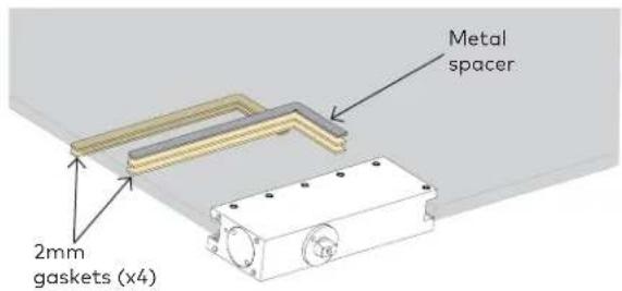
2.4.1 If have 1/2" [13] glass:
• Use one 2mm gasket on each side of the glass.
• Plus the included metal spacer.
2.4.2 If have 3/8" [10] glass:
- Use two 2mm gaskets on each side of the glass.
• Plus the included metal spacer.
2.5 Secure self-closing patch fitting to glass
Fig. 5

Hex key size
5mm
2.5.1 Secure self-closing fitting to glass.
- Tighten the six (6) hex screws.
- Use a 5mm hex key.
2.6A Option 1: Install door panel (with PT20/PT30)
Fig. 6
PLEASE NOTE ALL PT20 AND PT30 PATCH FITTING INSERTS' ORIENTATION MAY NEED TO BE REVERSED TO MEET THE NON-U.S.-STANDARD 2-5/8" [67] BACK SET WHICH IS NEEDED IN CONJUNCTION WITH A UNIVERSAL MOTION SELF-CLOSING PATCH FITTING. ENSURE TO FOLLOW THE DIRECTIONS BELOW CLOSELY.
![PT20 Pivot Point Wall Door panel 2-5/8" [67] from wall to center of insert Shown looking DOWN from top of patch fitting.](/content/2026/05/889561/images/ba1827311296757575d6c1099df1fdbbf52b7d0881067dabece51ab4d25663e4.jpg)
2.6.1 Mount PT20 and PT30 patch fittings to glass door and glass transom per PT20 and PT30 installation instructions.
2.6.2 Place PT20 insert into fitting, oriented as shown above.
NOTE: ENSURE INSERT IS ORIENTED CORRECTLY.
2.6.3 Secure insert with included fasteners.
- Tighten and torque accordingly.

| Torque value | |
| PT20 insert | 9 ft lbs [12Nm] |
| PT30 insert | 9 ft lbs [12Nm] |
Hex key size
5mm
![PT30 Pivot Point Wall Door panel 2-5/8" [67] from wall to center of insert Shown looking UP from bottom of patch fitting.](/content/2026/05/889561/images/54978f179f5e55231ec14e2570b5eb7875ac7f05ffa02e3747d5eec2dada1da0.jpg)
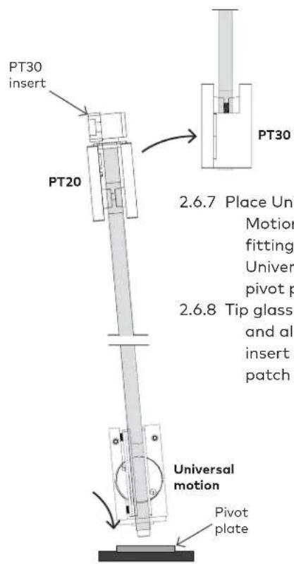
2.6.4 Place PT30 pivot pin into PT30 insert.
2.6.5 Secure with set screw.
2.6.6 Place PT30 insert assembly into top of PT20, oriented as shown above.
NOTE: ENSURE INSERT IS ORIENTED CORRECTLY.

2.6.9 Secure insert with included M6x16 socket head screws.
2.6B Option 2: Install door panel (with PT20/PT24)
Fig. 7
PLEASE NOTE ALL PT20 PATCH FITTING INSERTS AND PT24 PIVOT ORIENTATION MAY NEED TO BE REVERSED TO MEET THE NON-U.S.-STANDARD 2-5/8" [67] BACK SET WHICH IS NEEDED IN CONJUNCTION WITH A UNIVERSAL MOTION SELF-CLOSING PATCH FITTING. ENSURE TO FOLLOW THE DIRECTIONS BELOW CLOSELY.
PT24
pivot
PT20
insert
PT20 Pivot Point
PT24
pivot
PT20 plastic sleeve
2-5/8" [67] from
wall to center of
insert
Shown looking UP
from bottom of
patch fitting.
PT20
insert
2.6.1 Mount PT20 patch fitting to glass door per PT20 installation instructions.
2.6.2 Mount PT24 pivot to door frame per PT24 installation instructions.
2.6.3 Slide PT20 plastic sleeve and PT20 insert onto PT24 pivot.
NOTE: ENSURE INSERT IS ORIENTED CORRECTLY.
PT24
PT20
insert
PT24
PT20
2.6.4 Place Universal Motion
patching fitting into
Universal Motion pivot plate.
2.6.5 Tip glass panel up and
align PT20 patch fitting with PT20 insert.
2.6.6 Secure PT20 insert with
included M6x16 socket
head screws.
Hex key size
5mm
Universal
motion
Torque value
PT20 9 ft lbs
insert [12Nm]
Pivot
plate
2.6C Option 3: Install door panel (with PT20/PT40)
Fig. 8
PLEASE NOTE ALL PT20 AND PT40 PATCH FITTING INSERTS' ORIENTATION MAY NEED TO BE REVERSED TO MEET THE NON-U.S.-STANDARD 2-5/8" [67] BACK SET WHICH IS NEEDED IN CONJUNCTION WITH A UNIVERSAL MOTION SELF-CLOSING PATCH FITTING. ENSURE TO FOLLOW THE DIRECTIONS BELOW CLOSELY.
![PT20 Pivot Point Sidelite Door panel 2-5/8" [67] from sidelite to center of insert Shown looking DOWN from top of patch fitting.](/content/2026/05/889561/images/d336eb3cc1f79fb4d67e22d42f78a8df3f651ff0aea707684b9f91e7cfaed7a4.jpg)
2.6.1 Mount PT20 and PT40 patch fittings to glass door and glass transom per PT20 and PT40 installation instructions.
2.6.2 Place PT20 insert into fitting, oriented as shown above.
NOTE: ENSURE INSERT IS ORIENTED CORRECTLY.
2.6.3 Secure insert with included fasteners.
- Tighten and torque accordingly.

| Torque value | |
| PT20 insert | 9 ft lbs [12Nm] |
| PT40 insert | 9 ft lbs [12Nm] |
| Hex key size | |
| 5mm | |
![PT40 Pivot Point Sidelite Transom 2-5/8" [67] from sidelite to center of insert Shown looking UP from bottom of patch fitting.](/content/2026/05/889561/images/b60a3ad4a889d549f2d72c8c9dac857a7caf97f49bd364ac9122f7c6919a2154.jpg)
2.6.4 Place PT40 pivot pin into PT40 insert.
2.6.5 Secure with set screw.
2.6.6 Place PT40 insert assembly into top of PT20, oriented as shown above.
NOTE: ENSURE INSERT IS ORIENTED CORRECTLY.

2.6.7 Place Universal Motion patching fitting into Universal Motion pivot plate.
2.6.8 Tip glass up and align PT40 insert with PT40 patch fitting.

2.6.9 Secure insert with included M6x16 socket head screws.
2.7 Securing floor pivot plate
Fig. 9

2.7.1 Adjust Universal Motion pivot plate center section to ensure pivot pin correctly aligns with center section.
- Adjust via set screws (see dashed arrows above for reference).

natural_image
Technical diagram of a mechanical assembly with a curved arrow indicating rotation or movement (no text or symbols present)2.7.2 Rotate door 90° to gain access to side of patch fitting.

2.7.3 Adjust sweep and latch speeds as needed.
- Use valves #1 or #2.

Valve # Action Action opening angle
| 1 Sweep degree 140° - 45° |
| 2 Latch degree 45° - close |
2.8 Install covers
Fig. 10

2.8.1 Snap covers onto pivot plate.
2.8.2 Door must be rotated 90° to allow access for pivot plate covers.

2.8.3 Align holes in cover with pins on end of fitting.
2.8.4 Snap covers onto patch fitting.

2.8.5 To remove:
- Depress spring pins and pop cover off.
2.9.1 Install limiting door stop in preferred location.
NOTE: Ensure door does not open farther than 140^ maximum.
3 Adjustments
3.1 Adjusting hold open (optional)
Fig. 12

natural_image
Technical line drawing of a mechanical bracket assembly with mounting base and side panel (no text or symbols)
natural_image
Technical diagram of a mechanical assembly with a curved arrow indicating direction (no text or symbols present)
natural_image
Simple line drawing of a rectangular block with an arrow indicating rotation or movement (no text or symbols)3.1.1 To engage hold open:
- Push door open in either direction until hold open engages.
3.1.2 To disengage hold open:
- Pull door to pop door out of hold open.
• Maximum hold open 90° in either direction.

- Universal Motion
- Table of contents
- Technical specifications 3
- Installation instructions
- Technical specifications
- Overview
- Glass mounting
- General information
- Intended use
- Glass requirements/fittings/mounting
- Requirements for glass panel
- Safety instructions
- Symbols used - Safety/Installation
- CAUTION
- WARNING
- CLOSING EDGE OF DOOR
- Maintenance, care, repair
- Disposal
- Door dimensions & options
- Technical Data
- Overall
- Prepare floor and install pivot plate
- Install self-closing patch fitting on glass
- Install gaskets
- If have 1/2" [13] glass:
- If have 3/8" [10] glass:
- Secure self-closing patch fitting to glass
- Secure self-closing fitting to glass.
- 2.6A Option 1: Install door panel (with PT20/PT30)
- PLEASE NOTE ALL PT20 AND PT30 PATCH FITTING INSERTS' ORIENTATION MAY NEED TO BE REVERSED TO MEET THE NON-U.S.-STANDARD 2-5/8" [67] BACK SET WHICH IS NEEDED IN CONJUNCTION WITH A UNIVERSAL MOTION SELF-CLOSING PATCH FITTING. ENSURE TO FOLLOW THE DIRECTIONS BELOW CLOSELY.
- NOTE: ENSURE INSERT IS ORIENTED CORRECTLY.
- 2.6B Option 2: Install door panel (with PT20/PT24)
- PLEASE NOTE ALL PT20 PATCH FITTING INSERTS AND PT24 PIVOT ORIENTATION MAY NEED TO BE REVERSED TO MEET THE NON-U.S.-STANDARD 2-5/8" [67] BACK SET WHICH IS NEEDED IN CONJUNCTION WITH A UNIVERSAL MOTION SELF-CLOSING PATCH FITTING. ENSURE TO FOLLOW THE DIRECTIONS BELOW CLOSELY.
- 2.6C Option 3: Install door panel (with PT20/PT40)
- PLEASE NOTE ALL PT20 AND PT40 PATCH FITTING INSERTS' ORIENTATION MAY NEED TO BE REVERSED TO MEET THE NON-U.S.-STANDARD 2-5/8" [67] BACK SET WHICH IS NEEDED IN CONJUNCTION WITH A UNIVERSAL MOTION SELF-CLOSING PATCH FITTING. ENSURE TO FOLLOW THE DIRECTIONS BELOW CLOSELY.
- Securing floor pivot plate
- Install covers
- To remove:
- Adjustments
- Adjusting hold open (optional)
- To engage hold open:
- To disengage hold open:
Brand : Dormakaba
Model : Universal Motion
Category : Door closer