A-156 - Uncategorized Doepfer - Free user manual and instructions
Find the device manual for free A-156 Doepfer in PDF.


| Product Type | Dual Control Voltage Quantizer |
| Brand | Doepfer |
| Model | A-156 QNT |
| Form Factor | Eurorack 3U module, 8 HP width |
| Dimensions (WxHxD) | 40.3 mm x 128.5 mm x 20 mm (approx.) |
| Weight | Approx. 100 g |
| Power Consumption | +12V: 40 mA, -12V: 10 mA (typical) |
| Control Voltage Input Range | 0 to +10 V |
| Control Voltage Output Range | 0 to +10 V (quantized) |
| Quantizer 1 Grid | Semitone (1/12 V) or same as quantizer 2 via jumper |
| Quantizer 2 Grid Options | Chromatic, major scale, minor scale, major chord, minor chord, fundamental+fifth, plus sixth or seventh |
| Trigger Input | Low/high transition causes quantization; internal rate ~500 Hz if unconnected |
| Trigger Output | ~10 ms pulse on each quantization step; retriggering possible |
| Transpose Input | Common CV input, quantized to semitone, added to both outputs |
| Controls | 3-position switches for scale (all/major/minor), mode (scale/chord/quint), and added interval (-/+6/+7) |
| Connectors | 8x 3.5 mm mono jacks (2x CV in, 2x CV out, 2x trig in, 2x trig out) + 1x transpose CV in |
| Maintenance | Wipe with dry cloth; avoid liquids and cleaning solvents |
| Safety | Disconnect power before patching or modifying jumpers; use only in dry environments |
| Spare Parts / Repairability | No user-serviceable parts; contact Doepfer or authorized service for repairs |
| Included Accessories | Module only; standard Eurorack power cable |
Frequently Asked Questions - A-156 Doepfer
User questions about A-156 Doepfer
0 question about this device. Answer the ones you know or ask your own.
Ask a new question about this device
Download the instructions for your Uncategorized in PDF format for free! Find your manual A-156 - Doepfer and take your electronic device back in hand. On this page are published all the documents necessary for the use of your device. A-156 by Doepfer.
USER MANUAL A-156 Doepfer
flowchart
graph TD
    A["A-156 QNT"] --> B["CV In"]
    A --> C["CV Out"]
    A --> D["Trig. In"]
    A --> E["Trig. Out"]
    F["Transpose CV 1+2"] --> G["Options"]
    style F fill:#f9f,stroke:#333
    style G fill:#ccf,stroke:#333
1. Introduction
Module A-156 (QNT) is a dual control voltage quantizer.
For each of the two sections, the control voltage applied to the input is converted into the nearest quantized (i.e. terraced or stepped) voltage, and sent to the control voltage output. Any voltage between 0 and 10V is acceptable.
Quantizer 1 provides the usual semitone grid (i.e. steps of 1/12 V) whereas quantizer 2 enables more elaborate grid settings like major or minor scales or chords. If desired quantizer 1 can use the same grid settings as quantizer 2.
The trigger inputs allow the synchronization of the quantizing processes to other events (e.g. envelope trigger, analog sequencer clock, MIDI clock).
The trigger outputs transmit a trigger pulse whenever quantization takes place.
The transpose input is common for both quantizers and enables the transposition of both output voltages.
2. Overview
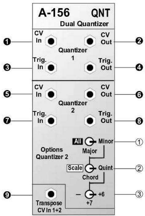
Controls:
① switch : 3-position switch for scale type (chromatic, major, minor)
② switch : 3-position switch for mode (scale, chord, fundamental + fifth)
③ switch : 3-position switch for additional sixth or seventh
In / Outputs:
①, ⑤ CV In : Control voltage inputs
②, ⑥ CV Out : Control voltage outputs (quantized)
③, ⑦ Trig. In : Trigger inputs
④, ⑧ Trig. Out : Trigger outputs
⑨ Transpose : Transpose control voltage input for simultaneous transposition of quantizer 1 and 2
3. Basic Principles
A quantizer consists of an analog/digital converter (ADC) and a digital/analog converter (DAC). The voltage applied to the analog input of the ADC is converted into digital information (e.g. 6 bit = 64 steps). The DAC converts this digital information back into a quantized analog voltage in the same voltage range. For pitch control voltage applications following the 1V/oct standard an ADC resolution of 1/12V (= 0.0833V) is used.
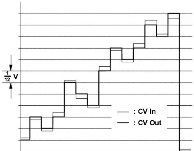
Module A-156 contains 2 quantizers. The factory setting for quantizer 1 is a semitone grid (i.e. voltage steps of 1/12 V, see fig. 1).

If the position of jumper J1 on the A-156 circuit board is changed the first quantizer has the same features as quantizer 2, i.e. the 3 switches determine the behaviour of quantizer 1 as well.
Quantizer 2 enables other grids than just semitones, e.g. major scale, minor scale, major chord, minor chord, fundamental + fifth and the addition of a sixth or seventh to chords. This means that only such voltages appear at the control voltage output that meet the selection criteria (e.g. minor chord with seventh) set by the 3 switches.
line
| Time | CV In | CV Out | |------|-------|--------| | 0 | 0 | 0 | | 1/12 | 1/12 | 1/12 | | 2/12 | 2/12 | 2/12 | | 3/12 | 3/12 | 3/12 | | 4/12 | 4/12 | 4/12 | | 5/12 | 5/12 | 5/12 | | 6/12 | 6/12 | 6/12 | | 7/12 | 7/12 | 7/12 | | 8/12 | 8/12 | 8/12 | | 9/12 | 9/12 | 9/12 | | 10/12| 10/12 | 10/12 | | 11/12| 11/12 | 11/12 | | 12/12| 12/12 | 12/12 | | 13/12| 13/12 | 13/12 | | 14/12| 14/12 | 14/12 | | 15/12| 15/12 | 15/12 | | 16/12| 16/12 | 16/12 | | 17/12| 17/12 | 17/12 | | 18/12| 18/12 | 18/12 | | 19/12| 19/12 | 19/12 | | 20/12| 20/12 | 20/12 | | 21/12| 21/12 | 21/12 | | 22/12| 22/12 | 22/12 | | 23/12| 23/12 | 23/12 | | 24/12| 24/12 | 24/12 | | 25/12| 25/12 | 25/12 | | 26/12| 26/12 | 26/12 | | 27/12| 27/12 | 27/12 | | 28/12| 28/12 | 28/12 | | 29/12| 29/12 | 29/12 | | 30/12| 30/12 | 30/12 | | 31/12| 31/12 | 31/12 | | 32/12| 32/12 | 32/12 | | 33/12| 33/12 | 33/12 | | 34/12| 34/12 | 34/12 | | 35/12| 35/12 | 35/12 | | 36/12| 36/12 | 36/12 | | 37/12| 37/12 | 37/12 | | 38/12| 38/12 | 38/12 | | 39/12| 39/12 | 39/12 | | 40/12| 40/12 | 40/12 | | 41/12| 41/12 | 41/12 | | 42/12| 42/12 | 42/12 | | 43/12| 43/12 | 43/12 | | 44/12| 44/12 | 44/12 | | 45/12| 45/12 | 45/12 | | 46/12| 46/12 | 46/12 | | 47/12| 47/12 | 47/12 | | 48/12| 48/12 | 48/12 | | 49/12| 49/12 | 49/12 | | 50/12| 50/12 | 50/12 | | ... (repeated) | ... (repeated) | ... (repeated) | | End | ... | ... |fig. 1: Quantizing in a semitone grid (1/12 V)
Quantization takes place continuously if the trigger input of the quantizer in question is not used (i.e. if nothing is plugged into the trigger input socket). The internal quantizing rate is about 500 Hz in this case. If a rectangle signal is applied to the trigger input (e.g. from an LFO, sequencer trigger output, MIDI-to-Sync interface) the quantization happens only during the low/high transition of the trigger input signal. Thus the quantization process can be synchronized to other events.
4. Controls
① Switch
The 3-position switch ① determines the scale type.
In position "All" a chromatic scale (see fig. 2) is used, i.e. the voltage step is 1/12 V.

In this case switches ② and ③ have no function.

fig. 2: chromatic scale (semitone grid)
In the "Major" position major chords or major scales are generated depending upon the position of switch ②.
In the "Minor" position minor chords or minor scales are generated depending upon the position of switch ②.
② Switch
The 3-position switch ② determines the output mode.
In the "Scale" position all voltages corresponding to the scale selected with switch ① (major or minor) are passed to the control voltage output (see fig. 3).
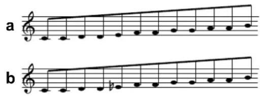
fig. 3: Major scale (a) and minor scale (b)
During scanning of the control voltage all 12 steps of an octave are generated. Therefore some steps appear twice in the graph above. The same is valid for all other grids too.
In the "Chord" position only voltages corresponding to the chord type selected with switch ① (major or minor) are passed to the control voltage output (see fig. 4a+b).
In the "Quint" position only voltages corresponding to the fundamental or the fifth are passed to the control voltage output (see fig. 4 c).
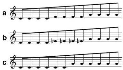
fig. 4: Major chord (a), minor chord (b) and fundamental+fifth (c)
If switch ① is in the "All" position, switch ② has no function.
③ Switch
The 3-position switch ③ enables the addition of a sixth (pos. +6) or a (minor) seventh (pos. +7) if switch ② is in position "Chord" (see fig 5 a, b, c, d) or "Quint" (see fig. 5 e, f). In the middle position "-" neither is added.
If switch ① is in the "All" position the switches ② and ③ have no function. Likewise switch ③ has no function if ② is in the "Scale" position.
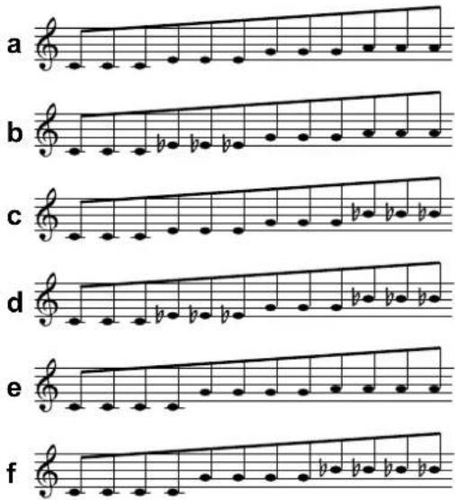
fig. 5: Addition of a sixth (a, b, e), and seventh (c, d, f)
5. In / Outputs
① CV In • ⑤ CV In
Socket ① and ⑤ are the inputs for the quantizers 1 and 2 respectively. The control voltage to be quantized is patched into these sockets.
② CV Out • ⑥ CV Out
At outputs ② and ⑥ the quantized voltages appear.
③ Trig. In • ⑦ Trig. In
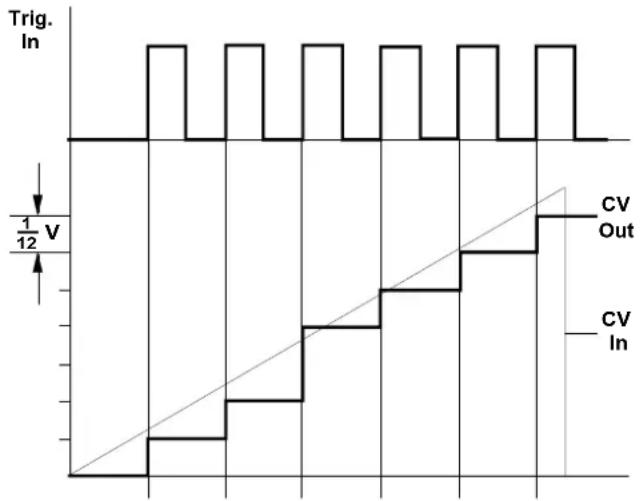
If a trigger signal is applied to the trigger input ③ or ⑦ the quantization process takes place during low/high transition of the trigger signal. If this is not desired leave the socket un-connected. Quantization then takes place at the internal rate of about 500Hz.
The external trigger signals are scanned with a rate of about 1kHz. Therefore the external trigger frequency has to be less than 500Hz to avoid aliasing effects. In practice this will be no restriction as normal quantization rates are much lower (usually only a few Hz).
line
| Time (ns) | Trig. In (V) | CV In (V) | | --------- | ------------ | --------- | | 0 | 0 | 0 | | 1 | 1 | 0.5 | | 2 | 0 | 1 | | 3 | 1 | 0.5 | | 4 | 0 | 1 | | 5 | 1 | 0.5 | | 6 | 0 | 1 | | 7 | 1 | 0.5 | | 8 | 0 | 1 | | 9 | 1 | 0.5 | | 10 | 0 | 1 | | 11 | 1 | 0.5 | | 12 | 0 | 1 | | 13 | 1 | 0.5 | | 14 | 0 | 1 | | 15 | 1 | 0.5 | | 16 | 0 | 1 | | 17 | 1 | 0.5 | | 18 | 0 | 1 | | 19 | 1 | 0.5 | | 20 | 0 | 1 | | 21 | 1 | 0.5 | | 22 | 0 | 1 | | 23 | 1 | 0.5 | | 24 | 0 | 1 | | 25 | 1 | 0.5 | | 26 | 0 | 1 | | 27 | 1 | 0.5 | | 28 | 0 | 1 | | 29 | 1 | 0.5 | | 30 | 0 | 1 | | 31 | 1 | 0.5 | | 32 | 0 | 1 | | 33 | 1 | 0.5 | | 34 | 0 | 1 | | 35 | 1 | 0.5 | | 36 | 0 | 1 | | 37 | 1 | 0.5 | | 38 | 0 | 1 | | 39 | 1 | 0.5 | | 40 | 0 | 1 | | 41 | 1 | 0.5 | | 42 | 0 | 1 | | 43 | 1 | 0.5 | | 44 | 0 | 1 | | 45 | 1 | 0.5 | | 46 | 0 | 1 | | 47 | 1 | 0.5 | | 48 | 0 | 1 | | 49 | 1 | 0.5 | | 50 | 0 | 1 | | 51 | 1 | 0.5 | | 52 | 0 | 1 | | 53 | 1 | 0.5 | | 54 | 0 | 1 | | 55 | 1 | 0.5 | | 56 | 0 | 1 | | 57 | 1 | 0.5 | | 58 | 0 | 1 | | 59 | 1 | 0.5 | | 60 | 0 | 1 | | Note: The actual values for Trig. In and CV In are not provided in the code. The CSV data is extracted directly from the image. The values for each trace are explicitly labeled on the graph.fig. 6: External triggered quantization
④ Trig. Out • ⑧ Trig. Out
At the trigger outputs ④ and ③ a trigger pulse of about 10ms duration is output whenever quantization takes place, i.e. if the output voltage at the control voltage output ② or ⑥ changes. For example this output can be used to trigger a envelope generator (ADSR) with each new quantization step.

The pulsewidth is fixed to 10 ms. If during this 10 ms a new trigger signal has to be generated, re-triggering takes place. In this case a 5ms pulse appears before the next 10ms pulse is generated.
⑨ Transposing CV 1+2
The transpose input ⑨ enables the simultaneous transposition of both quantizer outputs. The voltage at the transpose input ⑨ is quantized to the nearest semitone, and effects both quantizers, i.e. the voltage at the transpose input is quantized and added to both quantizer outputs.
Example: A voltage of +1.0 V applied to the transpose input shifts both quantizer one octave up.

As the input and output range for all control voltages is 0...+10 V the CV outputs ② and ⑥ stop at +10 V if the addition of input CV and transpose CV would exceed +10V.
6. User examples
There are manifold applications for the A-156 as any control voltage can be used as a voltage source for the quantizer (e.g. LFO, Random, ADSR, Theremin, Light-controlled voltage, Foot controller, Analog sequencer, MIDI-controlled voltages).
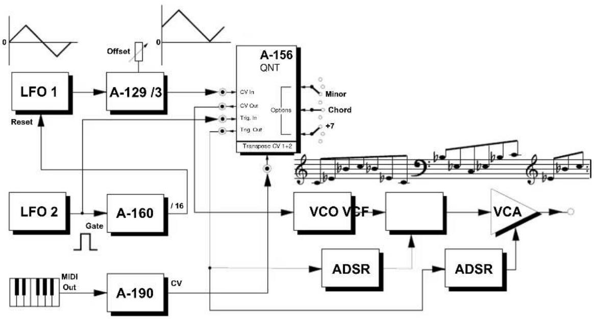
Arpeggio-like effects, especially, can be realized very easily. The patch in fig. 7 can be used as a basic set-up for further experiments.
LFO1 (slow triangle wave) serves as the control voltage source for the quantizer. As the quantizer accepts only positive voltages the attenuator/offset generator A-129/3 has to be used to process negative or symmetrical (i.e. positive/negative) voltages like the LFO output. The A-129/3 converts the symmetrical voltage of the LFO into a purely positive voltage by adding an adjustable fixed positive voltage.
LFO2 (rectangle output) generates a trigger signal. Each low/high transition causes the quantizer to pick out the current voltage of LFO1 and to quantize it, depending on the mode selected (e.g. minor with added seventh).
When a MIDI keyboard is used the arpeggios can be transposed using a MIDI-to-CV-Interface (A-190).
In the patch in fig. 7 LFO1 is reset every 16 trigger events to obtain a periodic arpeggio with 16 "notes".

Which arpeggio notes are affected by the quantization depends upon the relation of the LFO frequencies. Try different settings for LFO frequencies.
Try also a modified patch without Clock Divider A-160 and without resetting LFO1. In this case the LFOs oscillate without synchronization and the arpeggio length depends upon the frequency relation of LFO1 and LFO2. Very interesting arpeggios appear if the LFO frequencies are not whole number multiples as the patterns then don't repeat.

Try other control voltages instead of LFO1, e.g. random, analog or digital noise, There-min, ADSR or others. You will obtain random or non-random patterns that always match with the grid selected.
flowchart
graph TD
    A["LFO 1"] --> B["A-129 /3"]
    B --> C["Transpase CV 1+2"]
    D["LFO 2"] --> E["A-160"]
    E --> F["VCO VCF"]
    F --> G["VCA"]
    H["MIDI Out"] --> I["A-190"]
    I --> J["CV"]
    K["Offset"] --> B
    L["Reset"] --> B
    M["Minor"] --> N["Chord"]
    O["+7"] --> N
    P["Offsets"] --> Q["Waveform Signal"]
    R["Gate"] --> S["Input Signal"]
    T["Feedback Lines"] --> U["Feedback Lines"]
    V["Adsr"] --> W["ADSR"]
    X["Adsr"] --> Y["ADSR"]
fig 7: arpeggio-like sound patterns
If an ADSR is used as a control voltage source the A-129/3 is no longer required as the ADSR generates only positive voltages.
One very interesting combination is with a Theremin module A-178 as the continuous voltage from the Theremin is converted into "musically correct" intervals by the quantizer, e.g. only notes from a major scale.
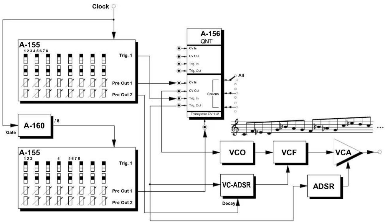
Another typical application is shown in fig. 8: using the Quantizer A-156 with the Analog/Trigger Sequenzer A-155.
The upper sequencer generates an 8-note sequence. The voltage "Pre Out 1" controls the VCO pitch and is processed by the quantizer to obtain exact tunings. Without the quantizer it would be very difficult to obtain the correct intervals.
The lower sequencer is synchronized to the upper and runs at 1/8 speed (output "/8" of the Clock Divider A-160 used as clock input). The lower sequencer controls the transpose input ⑨ on the quantizer. Consequently the sequence on the upper sequencer is transposed by the lower sequencer as after each pass of the upper sequencer the lower sequencer advances to the next step.

Instead of the lower sequencer a MIDI keyboard in combination with a MIDI-to-CV interface (A-190) may be used for transposition (see fig. 7).

Instead of the lower sequencer also a random voltage (A-118 Random voltage or combination of Noise and S&H triggered by A-160) may be used. In this case one obtains random transpositions. If it is desired that the transpositions match with certain scales (e.g. major chord) that can be adjusted independently of the quantizer already in use another quantizer is required.
flowchart
graph TD
    Clock --> A155["1 2 3 4 5 6 7 8"]
    A155 --> Trig1["Trig. 1"]
    Trig1 --> PreOut1["Pre Out 1"]
    Trig1 --> PreOut2["Pre Out 2"]
    PreOut1 --> A160["A-160"]
    PreOut2 --> A160
    A160 --> Gate["Gate"]
    A155 --> Trig1a["Trig. 1"]
    Trig1a --> PreOut1a["Pre Out 1"]
    Trig1a --> PreOut2a["Pre Out 2"]
    PreOut1a --> A155b["1 2 3"]
    PreOut2a --> A155b
    A155b --> Gate
    A155 --> Trig1c["Trig. 1"]
    A155 --> PreOut2a["Pre Out 2"]
    A156["QNT"] --> TransposeCV1.2["Transpose CV 1.2"]
    TransposeCV1.2 --> Options["Options"]
    Options --> A156
    A156 --> All["All"]
    VCO["VCO"] --> VCF["VCF"] --> VCA["VCA"] --> Adder
    VCO --> Adder
    VCF --> Adder
    Adder --> VCA
    Adder --> VCA
    Adder --> VCA
    Adder --> VCA
    Adder --> VCA
    Adder --> VCA
    Adder --> VCA
    Adder --> VCA
    Adder --> VCA
    Adder --> VCA
    Adder --> VCA
    Adder --> VCA
    Adder --> VCA
    Adder --> VCA
    Adder --> VCA
fig. 8: Sequencer and quantizer
7. Patch-Sheet
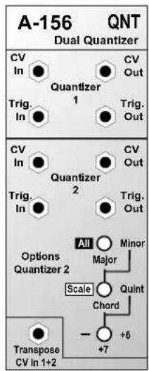
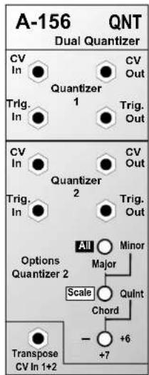
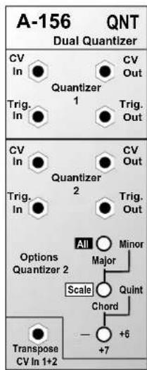
The following diagrams of the module can help you recall your own Patches. They're designed so that a complete 19" rack of modules will fit onto an A4 sheet of paper.
Photocopy this page, and cut out the pictures of this and your other modules. You can then stick them onto another piece of paper, and create a diagram of your own system.
Make multiple copies of your composite diagram, to use for remembering good patches and set-ups.

- Draw in patchleads with coloured pens
- Draw or write control settings in the little white circles
Brand : Doepfer
Model : A-156
Category : Uncategorized