
DA-78HR - Audio recorder TASCAM - Free user manual and instructions
Find the device manual for free DA-78HR TASCAM in PDF.


| Product Type | Digital Multitrack Recorder |
| Number of Tracks | 8 |
| Recording Resolution | 16-bit or 24-bit linear |
| Sampling Frequencies | 44.1 kHz, 48 kHz |
| Recording Medium | Hi8 MP or ME video cassette (NTSC or PAL) |
| Maximum Recording Time | 108 min with P6-120 tape (NTSC) |
| Analog Inputs (Balanced) | 8 channels, D-sub 25-pin female, +4 dBu, 20 kΩ |
| Analog Inputs (Unbalanced) | 8 x RCA, -10 dBV, 10 kΩ |
| Analog Outputs (Balanced) | 8 channels, D-sub 25-pin female, +4 dBu, 10 kΩ loaded |
| Analog Outputs (Unbalanced) | 8 x RCA, -10 dBV, 250 Ω |
| Digital I/O | TDIF-1 via D-sub 25-pin; SPDIF coaxial (RCA) for stereo submix |
| Synchronization | Word clock BNC (IN/OUT/THRU), timecode RCA (IN/OUT), MIDI, REMOTE/SYNC IN |
| Timecode Formats | 30 drop, 30 non-drop, 29.97 drop, 29.97 non-drop, 25, 24 fps |
| Varispeed Range | ±6% in 0.1% steps |
| Shuttle Speeds | 0.25x to 8x play speed (forward and reverse) |
| Dimensions (W x H x D) | 482 x 143 x 350 mm (19 x 5.6 x 13.8 in) |
| Weight | 8.1 kg (17.8 lb) |
| Power Requirements | USA/Canada: 120 VAC, 60 Hz; UK/Europe: 230 VAC, 50 Hz; Australia: 240 VAC, 50 Hz |
| Power Consumption | 34 W |
| Head Maintenance | Use cleaning tape via maintenance menu; check error rates and drum time |
| Safety | Do not remove cover; use grounded cord; keep away from moisture; refer servicing to qualified personnel |
| Optional Accessories | RC-898/828/808 remote, IF-AE8/IF-88SD/IF-TAD converters, RC-30P footswitch, TDIF-1EX extender |
| Repairability | No user-serviceable parts inside; contact qualified service technician for repairs |
Frequently Asked Questions - DA-78HR TASCAM
User questions about DA-78HR TASCAM
0 question about this device. Answer the ones you know or ask your own.
Ask a new question about this device
Download the instructions for your Audio recorder in PDF format for free! Find your manual DA-78HR - TASCAM and take your electronic device back in hand. On this page are published all the documents necessary for the use of your device. DA-78HR by TASCAM.
USER MANUAL DA-78HR TASCAM
TEAC Professional Division
DA-78HR
Digital Multitrack Recorder
D00524000A
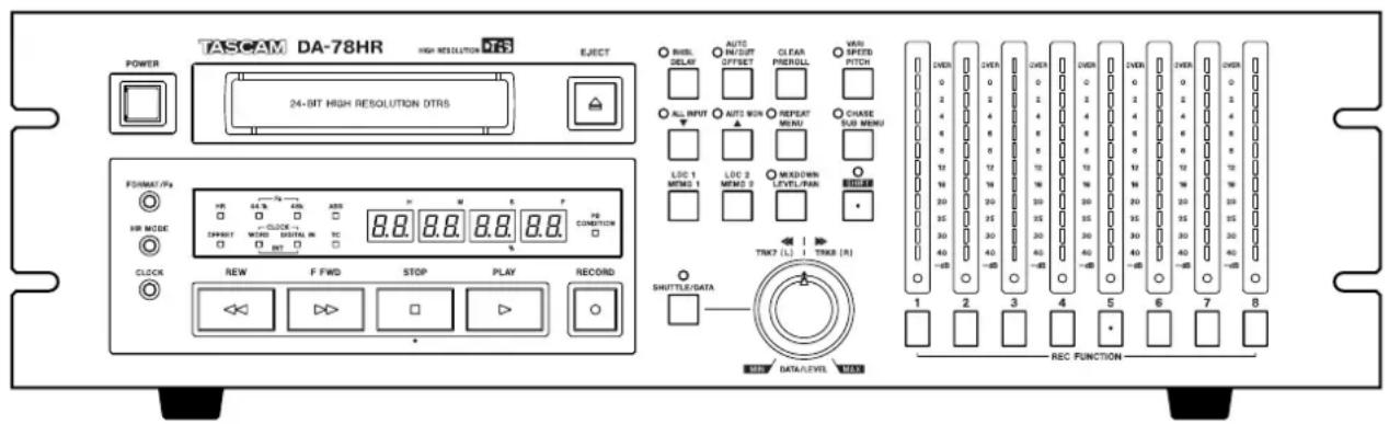
OWNER'S MANUAL

CAUTION
RISK OF ELECTRIC SHOCK
DO NOT OPEN

CAUTION: TO REDUCE THE RISK OF ELECTRIC SHOCK, DO NOT REMOVE COVER (OR BACK). NO USER-SERVICEABLE PARTS INSIDE. REFER SERVICING TO QUALIFIED SERVICE PERSONNEL.

The lightning flash with arrowhead symbol, within an equilateral triangle, is intended to alert the user to the presence of uninsulated “dangerous voltage” within the product’s enclosure that may be of sufficient magnitude to constitute a risk of electric shock to persons..

The exclamation point within an equilateral triangle is intended to alert the user to the presence of important operating and maintenance (servicing) instructions in the literature accompanying the appliance.
This appliance has a serial number located on the rear panel. Please record the model number and serial number and retain them for your records.
Model number
Serial number
WARNING: TO PREVENT FIRE OR SHOCK HAZARD, DO NOT EXPOSE THIS
APPLIANCE TO RAIN OR MOISTURE.
IMPORTANT (for U.K. Customers)
DO NOT cut off the mains plug from this equipment.
If the plug fitted is not suitable for the power points in your home or the cable is too short to reach a power point, then obtain an appropriate safety approved extension lead or consult your dealer.
If nonetheless the mains plug is cut off, remove the
fuse and dispose of the plug immediately, to avoid
a possible shock hazard by inadvertent connection to the mains supply.
If this product is not provided with a mains plug, or one has to be fitted, then follow the instructions given below:
IMPORTANT: The wires in this mains lead are coloured in accordance with the following code:
GREEN-AND-YELLOW : EARTH
BLUE : NEUTRAL
BROWN : LIVE
WARNING: This apparatus must be earthed.
As the colours of the wires in the mains lead of this apparatus may not correspond with the coloured markings identifying the terminals in your plug proceed as follows:
The wire which is coloured GREEN-and-YELLOW must be connected to the terminal in the plug which is marked by the letter E or by the safety earth symbol 12 or coloured GREEN or GREEN-and-YELLOW.
The wire which is coloured BLUE must be connected to the terminal which is marked with the letter N or coloured BLACK.
The wire which is coloured BROWN must be connected to the terminal which is marked with the letter L or coloured RED.
When replacing the fuse only a correctly rated approved type should be used and be sure to re-fit the fuse cover.
IF IN DOUBT — CONSULT A COMPETENT ELECTRICIAN.
For U.S.A
TO THE USER
This equipment has been tested and found to comply with the limits for a Class A digital device, pursuant to Part 15 of the FCC Rules. These limits are designed to provide reasonable protection against harmful interference when the equipment is operated in a commercial environment. This equipment generates, uses, and can radiate radio frequency energy and, if not installed and used in accordance with the instruction manual, may cause harmful interference to radio communications.
Operation of this equipment in a residential area is likely to cause harmful interference in which case the user will be required to correct the interference at his own expense.
CAUTION
Changes or modifications to this equipment not expressly approved by TEAC CORPORATION for compliance could void the user's authority to operate this equipment.
For the consumers in Europe
WARNING
This is a Class A product. In a domestic environment, this product may cause radio interference in which case the user may be required to take adequate measures.
IMPORTANT SAFETY INSTRUCTIONS
CAUTION:
- Read all of these Instructions.
- Save these Instructions for later use.
- Follow all Warnings and Instructions marked on the audio equipment.
1) Read Instructions — All the safety and operating instructions should be read before the product is operated.
2) Retain Instructions — The safety and operating instructions should be retained for future reference.
3) Heed Warnings — All warnings on the product and in the operating instructions should be adhered to.
4) Follow Instructions — All operating and use instructions should be followed.
5) Cleaning — Unplug this product from the wall outlet before cleaning. Do not use liquid cleaners or aerosol cleaners. Use a damp cloth for cleaning.
6) Attachments — Do not use attachments not recommended by the product manufacturer as they may cause hazards.
7) Water and Moisture — Do not use this product near water — for example, near a bath tub, wash bowl, kitchen sink, or laundry tub; in a wet basement; or near a swimming pool; and the like.
8) Accessories — Do not place this product on an unstable cart, stand, tripod, bracket, or table. The product may fall, causing serious injury to a child or adult, and serious damage to the product. Use only with a cart, stand, tripod, bracket, or table recommended by the manufacturer, or sold with the product. Any mounting of the product should follow the manufacturer's instructions, and should use a mounting accessory recommended by the manufacturer.
9) A product and cart combination should be moved with care. Quick stops, excessive force, and uneven surfaces may cause the product and cart combination to overturn.

natural_image
Symbolic icon of a person pushing a large object under a circular background (no text or symbols)10) Ventilation — Slots and openings in the cabinet are provided for ventilation and to ensure reliable operation of the product and to protect it from overheating, and these openings must not be blocked or covered. The openings should never be blocked by placing the product on a bed, sofa, rug, or other similar surface. This product should not be placed in a built-in installation such as a bookcase or rack unless proper ventilation is provided or the manufacturer's instructions have been adhered to.
11) Power Sources — This product should be operated only from the type of power source indicated on the marking label. If you are not sure of the type of power supply to your home, consult your product dealer or local power company. For products intended to operate from battery power, or other sources, refer to the operating instructions.
12) Grounding or Polarization— This product may be equipped with a polarized alternating-current line plug (a plug having one blade wider than the other). This plug will fit into the power outlet only one way. This is a safety feature. If you are unable to insert the plug fully into the outlet, try reversing the plug. If the plug should still fail to fit, contact your electrician to replace your obsolete outlet. Do not defeat the safety purpose of the polarized plug.
13) Power-Cord Protection — Power-supply cords should be routed so that they are not likely to be walked on or pinched by items placed upon or against them, paying particular attention to cords at plugs, convenience receptacles, and the point where they exit from the product.
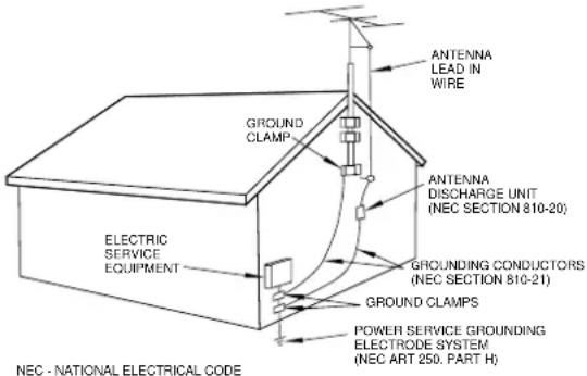
14) Outdoor Antenna Grounding — If an outside antenna or cable system is connected to the product, be sure the antenna or cable system is grounded so as to provide some protection against voltage surges and built-up static charges. Article 810 of the National Electrical Code, ANSI/NFPA 70, provides information with regard to proper grounding of the mast and supporting structure, grounding of the lead-in wire to an antenna discharge unit, size of grounding conductors, location of antenna-discharge unit, connection to grounding electrodes, and requirements for the grounding electrode.
"Note to CATV system installer:
This reminder is provided to call the CATV system installer's attention to Section 820-40 of the NEC which provides guidelines for proper grounding and, in particular, specifies that the cable ground shall be connected to the grounding system of the building, as close to the point of cable entry as practical.
Example of Antenna Grounding as per National Electrical Code, ANSI/NFPA 70
15) Lightning — For added protection for this product during a lightning storm, or when it is left unattended and unused for long periods of time, unplug it from the wall outlet and disconnect the antenna or cable system. This will prevent damage to the product due to lightning and power-line surges.
16) Power Lines — An outside antenna system should not be located in the vicinity of overhead power lines or other electric light or power circuits, or where it can fall into such power lines or circuits. When installing an outside antenna system, extreme care should be taken to keep from touching such power lines or circuits as contact with them might be fatal.
17) Overloading — Do not overload wall outlets, extension cords, or integral convenience receptacles as this can result in risk of fire or electric shock.
18) Object and Liquid Entry — Never push objects of any kind into this product through openings as they may touch dangerous voltage points or short-out parts that could result in a fire or electric shock. Never spill liquid of any kind on the product.
19) Servicing — Do not attempt to service this product yourself as opening or removing covers may expose you to dangerous voltage or other hazards. Refer all servicing to qualified service personnel.
20) Damage Requiring Service — Unplug this product from the wall outlet and refer servicing to qualified service personnel under the following conditions:
a) when the power-supply cord or plug is damaged.
b) if liquid has been spilled, or objects have fallen into the product.
c) if the product has been exposed to rain or water.
d) if the product does not operate normally by following the operating instructions. Adjust only those controls that are covered by the operating instructions as an improper adjustment of other controls may result in damage and will often require extensive work by a qualified technician to restore the product to its normal operation.
e) if the product has been dropped or damaged in any way.
f) when the product exhibits a distinct change in performance – this indicates a need for service.
21) Replacement Parts — When replacement parts are required, be sure the service technician has used replacement parts specified by the manufacturer or have the same characteristics as the original part.
Unauthorized substitutions may result in fire, electric shock, or other hazards.
22) Safety Check — Upon completion of any service or repairs to this product, ask the service technician to perform safety checks to determine that the product is in proper operating condition.
23) Wall or Ceiling Mounting—The product should be mounted to a wall or ceiling only as recommended by the manufacturer.
24) Heat — The product should be situated away from heat sources such as radiators, heat registers, stoves, or other products (including amplifiers) that produce heat.
Table of Contents
1 - Introduction to the DA-78HR
1.1 Unpacking ...... 7
1.2 Features....7
1.3 Using this manual....7
1.4 Precautions and recommendations 8
1.4.1 Clock source in a digital studio..... 8
1.4.2 HR recording and emphasis ..... 8
1.4.3 Environmental conditions....8
1.4.4 Installing the DA-78HR....9
1.4.5 Electrical considerations ...... 9
1.4.6 Three-core power cord.... 9
1.4.7 Powering the DA-78HR off and on... 9
1.4.8 Condensation....9
1.5 Recommended tapes.... 9
1.5.1 Tape brands.... 10
1.5.2 Available recording and playback time.... 11
2 - Front and rear panel features
2.1 General controls and indicators..... 13
① Power switch ....13
② Tape loading slot and EJECT key ..... 13
③ FORMAT/Fs key 13
④ HR MODE key 13
⑤ CLOCK key 13
⑥ Status indicators 13
⑦ Tape counter 13
⑧ PB CONDITION indicator 13
2.2 Tape transport keys and controls ... 13
⑨ REW key 13
⑩ F FWD key 13
11 STOP key 14
⑫ PLAY key 14
13 RECORD key 14
⑭ DATA/LEVEL control 14
2.3 System control keys.... 14
15 SHIFT key and indicator .....14
16 RHSL (DELAY) key and indicator ..... 14
17 AUTO IN/OUT (OFFSET) key and indicator 14
18 CLEAR (PRE ROLL) key 14
⑲ VARI SPEED / PITCH key and indicator 14
20 ALL INPUT (▼) key and indicator ..... 14
② AUTO MON ( ▲) key and indicator ..... 14
② REPEAT (MENU) key and indicator ....15
②3 CHASE (SUB MENU) key and indicator 15
⑳ LOC 1 (MEMO 1) key 15
25 LOC 2 (MEMO 2) key 15
26 MIXDOWN (LEVEL/PAN) key and indicator 15
2.4 Track controls.... 15
27 REC FUNCTION keys and indicators . 15
28 Peak meters 15
2.5 Rear panel features.....15
29 REMOTE IN/SYNC IN ....15
30 MIDI IN/OUT/THRU 15
③1 SYNC OUT 15
③2 REMOTE IN ....15
③3 REMOTE PUNCH IN/OUT .....16
③4 TDIF-1 (DIGITAL I/O) ......16
35 TIME CODE (IN, OUT) 16
36 WORD SYNC (IN, OUT, THRU) .....16
③7 DIGITAL IN, OUT (COAXIAL) .....16
38 ANALOG INPUTS (unbalanced) .....16
⑲39 ANALOG INPUTS (BALANCED) ......16
④0 ANALOG OUTPUTS (unbalanced) .....16
41 ANALOG OUTPUTS (BALANCED) .....16
④2 \~ IN ....16
3 - Connections
3.1 Audio connections....17
3.1.1 Balanced analog audio connections17
3.1.2 Unbalanced analog audio connections ....17
3.1.3 Digital audio connections....17
3.1.4 SPDIF connectors....18
3.2 Synchronization connections.....18
3.2.1 Word clock connections....18
3.2.2 MIDI connectors (IN, OUT and THRU) 18
3.2.3 Timecode connections....18
3.2.4 MIDI timecode connections .....18
3.3 Connection to other TASCAM units18
3.3.1 REMOTE IN....18
3.3.2 Footswitch....18
3.3.3 Multiple DTRS units....18
3.3.4 "Indirect" word sync....19
4 - Menu interface, etc.
4.1 The display ....20
4.1.1 Peak meters....20
4.2 The SHIFT key....20
4.2.1 Shifted keys....20
4.2.2 Shift mode.....20
4.3 Menus and sub-menus .....21
4.3.1 Exiting menu mode....21
4.3.2 Sub-menus....21
4.3.3 Adjusting parameter values......21
4.3.4 Resetting parameters to default values .....21
4.3.5 "Left" and "right" keys.....22
4.3.6 Sub-frame values.....22
4.3.7 Using the DATA/LEVEL knob to set values .....22
4.4 SYSTEM menu....23
4.5 AUDIO1 menu....23
4.6 AUDIO2 menu....24
4.7 TC menu....24
4.8 TC chase menu....25
4.9 TC generator menu .....25
4.10 MIDI menu....25
4.11 Maintenance menu....26
4.12 Dedicated keys ......26
5 - Basic operations
5.1 Formatting a tape ......27
5.1.1 Selecting a word clock source..... 27
5.1.2 Formatting.... 27
5.1.3 Aborting the format process...... 28
5.1.4 Recording while formatting..... 28
5.2 Recording the first tracks.....28
5.2.1 Preparing to record....28
5.2.2 Selecting a clock source.....28
5.2.3 Write-protecting cassettes.... 28
5.2.4 Recording the first tracks (i).... 29
5.2.5 Recording the basic tracks (ii).....29
5.2.6Replaying the first tracks.... 29
5.3 Input selection....29
5.3.1 Digital input selection.... 29
5.3.2 Input patchbay routing.... 30
5.3.3 Track bouncing.... 30
5.3.4 Returning to ALL ANALOG setting. 31
5.4 More on digital recording ....31
5.4.1 Sampling frequency and word length 31
5.4.2 Selecting input word length.... 31
5.5 Overdubbing....31
5.6 Punch-in and punch-out....32
5.6.1 Automatic punch point setting..... 32
5.6.2 Setting punch points "on the fly".... 32
5.6.3 Setting punch points using the front panel.... 33
5.6.4 Editing the pre-roll and post-roll times.... 33
5.6.5 Rehearsing the punch-in....34
5.6.6 Interrupting a rehearsal or punch recording 34
5.6.7 Recording the punch-in.... 34
5.6.8 Replaying the punched material..... 34
5.6.9 Exiting punch-in mode.... 35
6 - Monitoring
6.1 ALL INPUT ....36
6.2 AUTO MON....36
6.3 Shuttle monitor....36
6.3.1 Enabling and disabling shuttle monitoring.... 36
6.4 Shuttle muting ....36
6.5 Summary of monitor modes .....37
7 - Advanced operations
7.1 Autolocation ....38
7.1.1 Setting MEMO 1 and MEMO 2 "on the fly" 38
7.1.2 Checking, editing and manually entering MEMO 1 and MEMO 2....38
7.1.3 Setting the location pre-roll time .....38
7.1.4 Moving to MEMO 1 and MEMO 2.....38
7.1.5 Location and playback....38
7.2 Repeat function....39
7.2.1 To start repeat play ....39
7.3 Track delay....39
7.4 Sub-mixer....40
7.4.1 Entering mixdown mode.....40
7.4.2 Setting the master level .....40
7.4.3 Leaving edit/pan setting mode.....40
7.4.4 Setting levels and pan positions.....40
7.4.5 Setting the sub-mixer input sources41
7.5 Crossfade times ....41
7.6 Vari speed (pitch control)......41
7.6.1 To set a non-standard speed.....41
7.7 Shuttle operations....42
7.7.1 Shuttle monitoring....42
7.7.2 Shuttle muting 42
7.8 Meter modes....42
7.8.1 Peak hold time....42
7.8.2 Meter ballistics....42
7.9 Sine oscillator....43
7.9.1 Recording the oscillator .....43
7.10 REC MUTE (recording silence) .....43
7.11 Dither....43
7.11.1 Selecting dither settings....44
7.12 Advanced output options......44
7.12.1 Output word length .....44
7.12.2 Output patchbay....44
7.13 Emulation....45
7.13 Emulation....45
7.14 Saving settings to tape....45
7.14 Saving settings to tape....45
7.14 Saving settings to tape....45
7.14 Saving settings to tape....45
7.14 Saving settings to tape....45
7.14 Saving settings to tape....45
7.14 Saving settings to tape....45
7.14 Saving settings to tape....45
7.14 Saving settings to tape....45
7.14 Saving settings to tape....45
7.14 Saving settings to tape....45
7.14 Saving settings to tape....45
7.14 Saving settings to tape....45
7.14 Saving settings to tape....45
7.15 Restoring settings from tape .....45
8 - Synchronization with other DTRS units
8.1 Synchronization connections......47
8.2 Machine ID and master/slave settings....47
8.2.1 Differences between DTRS models .47
8.2.2 Setting machine ID 48
8.2.3 Master/slave settings (CHASE mode)....48
8.3 Machine offset....48
8.3.1 Setting machine offset......48
8.3.2 Cancelling machine offset......48
8.3.3 Setting machine offset "on the fly".49
8.3.4 An example of setting offsets .....49
8.4 Digital dubbing....50
8.5 Synchronized formatting....50
Table of Contents
8.5.1 Recording while formatting.... 51
8.6 Individual clock mode 51
8.7 Error messages....51
9 - Operations related to timecode
9.1 ABS and timecode 52
9.1.1 ABS time....52
9.1.2 Tape timecode....52
9.1.3 Selecting TC or ABS timing .....52
9.2 Tape timecode mode 52
9.2.1 TAPE TC setting 53
9.2.2 ABS setting....53
9.3 Selecting the frame mode.... 53
9.4 Timecode input and output.....53
9.4.1 Showing input timecode.... 54
9.4.2 Timecode input timing....54
9.4.3 Timecode output ....54
9.4.4 MTC output ....54
9.4.5 Fast linear timecode (LTC) output... 55
9.4.6 Timecode output timing 55
9.5 Recording timecode 55
9.5.1 Selecting the timecode source..... 55
9.5.2 Recording timecode using the generator ....56
9.5.3 Generator modes 56
9.5.4 Synthesizing timecode from ABS timing 56
9.5.5 External timecode sources ..... 57
9.5.6 Recording timecode from external sources....57
9.5.7 Checking external timecode .... 57
9.5.8 Checking the frame mode of striped timecode 58
9.6 Chasing to timecode 58
9.6.1 Machine ID and timecode.... 58
9.6.2 Timecode offset 58
9.6.3 Setting timecode offset 58
9.6.4 Cancelling timecode offset 59
9.6.5 Setting timecode offset "on the fly" 59
9.6.6 Park position 59
9.6.7 Automatic park position setting..... 59
9.6.8 Absolute and relative difference..... 60
9.6.9 Rechasing timecode.... 60
9.6.10 Bypassing timecode errors...... 60
9.6.11 Individual recording while chasing timecode 60
10 - MIDI control
10.1 MMC enable and disable.... 62
10.1.1 Assigning a MIDI ID to the DA-78HR....62
10.1.2 MMC commands and the DA-78HR62
10.2 MMC Bit Map Array....63
10.3 MIDI Control Change ......65
10.4 MIDI System Exclusive......65
10.4.1 Identity Reply......65
10.4.2 TASCAM Exclusive messages .....65
10.4.3 Track delay....65
10.4.4 Crossfade 65
10.4.5 Machine offset....65
10.4.6 Track Copy Setup....66
10.4.7 Track Copy Enable 66
10.5 MIDI Implementation Chart......67
11 - Maintenance, etc.
11.1 Head and transport cleaning .....68
11.1.1 To clean the heads and transport..68
11.1.2 Checking error rates......68
11.1.3 Checking drum time....69
11.2 Backup memory initialization......69
11.3 Checking version numbers......69
11.3.1 Software upgrades ....70
12 - Options, specifications and reference
12.1 Options for the DA-78HR....71
12.1.1 RC-898 remote control unit....71
12.1.2 RC-828 remote control unit....71
12.1.3 RC-808 remote control unit....71
12.1.4 IF-AE8 AES/EBU digital audio converter ....71
12.1.5 IF-88SD SDIF-2 digital audio converter ....71
12.1.6 IF-TAD ADAT digital audio converter ....71
12.1.7 TDIF-1EX extender box .....71
12.1.8 Cables....71
12.2 Specifications....72
12.2.1 Tape recorder section....72
12.2.2 Analog inputs and outputs .....72
12.2.3 Digital inputs and outputs .....72
12.2.4 Remote/sync connectors .....72
12.2.5 Word sync terminals .....72
12.2.6 Timecode connectors....72
12.2.7 MIDI connectors....72
12.2.8 Remote control connectors....72
12.2.9 Physical specifications .....73
12.2.10 Power specifications....73
12.2.11 Audio specifications....73
The TASCAM DA-78HR is a digital audio multi-track recorder designed for use in a variety of applications, including video post-production and audio multitrack work.
It records 8 tracks of full-quality digital audio on standard Hi8 video cassettes using a specially-designed transport and head mechanism. Using this medium, up to 108 minutes of continuous recording is possible on a single NTSC “120” tape
Recording is carried out at either 24 or 16 bits of resolution, and digital data may be input at 16, 20 or 24 bits of resolution. Analog signals are converted to digital data using 64 times oversampling delta-sigma techniques.
The DA-78HR builds on the foundations laid by the TASCAM DA-88, DA-38 and DA-98 digital multi-track recorders, and retains compatibility with them. 16-bit tapes recorded on one of the DA series can be replayed and overdubbed on any other machine in the series, or any DTRS machine. 24-bit tapes can only be replayed in DA-78HR recorders,
1.1 Unpacking
The box contains the following.
• DA-78HR Digital Multitrack Recorder (x 1)
- Accessories:
-Rackmount screw kit (x 1)
-AC power cord, 2 m (6 ft.) long (x 1)
-This manual (x 1)
- Warranty card (x 1)
1.2 Features
Other key features of the DA-78HR include:
- TASCAM-exclusive high-performance/high wear resistive rotary 4-head mechanism with TASCAM original track layout (DTRS standard)
- Use of standard, low-cost media with long recording and playback times
- 24-bit or 16-bit linear quantization at either 44.1 kHz or 48 kHz provides CD-quality sound or better
-
Fast, frame-accurate tape location and positioning; end-to-end winding for a “120” tape is around 80 seconds
-
Direct digital synchronization of up to 16 DTRS recorders (128 tracks) without the use of any external synchronizer or controller
- Direct digital dubbing between DTRS units
- An internal digital patchbay, allowing input-to-track assignment and selection of digital, analog and off-tape sources without the use of external switching or routing equipment
- Internal 8 x 2 mixer (level and pan) for stereo replay of recorded tracks and output through a standard SPDIF connector without external mixing equipment
- SPDIF stereo input
- Balanced +4dBu analog inputs and outputs carried on a convenient compact D-sub connector
- Unbalanced -10 dBV connectors (RCA) for connection to semi-professional equipment
- 15-segment peak meters with user-selectable fall ballistics and variable hold time (including continuous peak hold)
- Meters also used for display of channel and track information
- Integral digital sine oscillator, providing signals at 440Hz and 1kHz for tuning and other frequencies for lineup purposes
- Digital input and output on a single convenient compact D-sub connector (TDIF-1 format)
- Settings carried out through a menu hierarchy
- SMPTE/EBU timecode input and output
• MIDI Time Code and MIDI Machine Control - Simplified source/tape monitoring functions with automatic switching
- Auto punch-in and punch-out with rehearsal mode
- 2-point full function autolocator with A–B repeat function.
- Variable speed recording and playback (up to 6.0% in 0.1% steps)
- Shuttle mode enables “rock and roll” audio positioning of key locations
- Data entry mode allows use of shuttle knob to set data values
1.3 Using this manual
We suggest that you take the trouble to read this manual through at least once before starting to use the DA-78HR. In this way, you will find out where to turn when you need answers.
We suggest that you make a special note of the section 1.4, “Precautions and recommendations” as these contain some information which is unique to the DA-78HR.
We also suggest that you also read, as this will help you when you come to perform basic operations.
When referring to a control or a connector on the DA-78HR, the name of the control or connector will be written in bold type, and may be followed by a number, as in the example below:
Holding down the PLAY key ⑫ and pressing the REC ⑬ key will start the recording process.
The numbers refer to the front and rear panel illustrations and description in this manual.
When referring to a word or phrase which appears on the display, the word or phrase will be written as follows:
$$ \bar {n} E \bar {n} o. 1 (\text { MEMO } 1). $$
If on-screen parameters are given as part of a display example, they may sometimes be shown in the following way, where the represents an unknown value:
id SEL 88 (ID SEL xx ), where xx is the machine ID
NOTE
Recording is an art as well as a science. A successful recording is often judged primarily on the quality of sound as art, and we obviously cannot guarantee that. A company that makes paint and brushes for artists cannot say that the paintings made with their products will be critically well-received. TASCAM can make no guarantee that the DA-78HR by itself will assure the quality of the recordings you make. Your skill as a technician and your abilities as an artist will be significant factors in the results you achieve.
1.4 Precautions and recommendations
As with any precision piece of electronic equipment, common-sense precautions apply with the DA-78HR.
However, there are a few extra precautions which apply to the DA-78HR, and we suggest that you make a note of these, to prolong the useful life of the DA-78HR.
1.4.1 Clock source in a digital studio
The DA-78HR can be used in a variety of situations, and with a variety of equipment, either digital or analog.
If you are working with more than one digital audio unit in your setup, you should note that all units must be driven by the same central clock source (“word clock” or “word sync”).
If different word clock sources are used throughout the setup, it is actually possible to damage speakers, etc. because of mismatches.
The DA-78HR can be designated as the word clock master for your studio, or can be slaved to external word clocks, using a convenient front-panel switch and standard BNC connectors.
Even though AES/EBU stereo digital audio signals are self-clocking, any AES/EBU format signals converted and fed to or from the DA-78HR must be synchronized at word level with the DA-78HR.
1.4.2 HR recording and emphasis
Recordings made in 24-bit (HR) mode do not use emphasis.
If an attempt is made to record a digital signal that contains emphasis using either the TDIF or the SPDIF digital audio inputs, the display shows E P EMP , and the signal is muted.
A digital emphasis circuit is provided, however, for compatibility with previous models of DTRS recorder.
Note that if a recording using emphasis is dubbed to the DA-78HR via the analog inputs, this signal will need to be modified appropriately.
1.4.3 Environmental conditions
The DA-78HR can be operated in most environments, but we suggest that you keep the environmental conditions within the following limits:
- Ambient temperature between 5^ and 35^ (41°F and 95°F).
- Relative humidity should be between 30% and 80% non-condensing
- There should be no strong magnetic fields (speakers, etc.) near the DA-78HR.
- Avoid spraying polish, insecticides, etc. near the DA-78HR.
NOTE
If you need to clean the DA-78HR, use a soft cloth, moistened if necessary with a little detergent and
water. Do not use abrasive cleaners or solvents such as alcohol or thinner.
Avoid subjecting the DA-78HR to jolts, sudden shocks, etc.
NOTE
If you have to return the unit for service or repair, use the original packing materials if possible. If the unit is to be transported to a recording location, etc., use a suitable transport case with sufficient shock protection.
TASCAM does not accept responsibility for damage resulting from neglect or accident.
1.4.4 Installing the DA-78HR
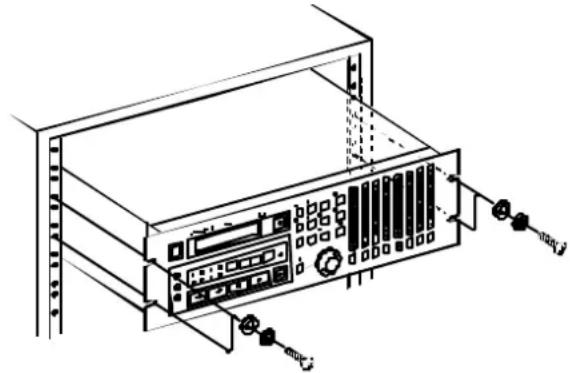
The DA-78HR may be installed in a standard 19" rack, occupying 3U of space. Since the DA-78HR is quite heavy (around between 7 and 8 kg – about 16 lb.), your rack should be strong and stable to take the weight of the DA-78HR.
The DA-78HR should be mounted with the front panel vertical.
natural_image
Technical line drawing of a rack-mounted server or server unit with ports and connectors (no text or symbols)1.4.5 Electrical considerations
Make sure that your local power supply matches the voltage requirements marked on the rear panel of the DA-78HR.
If you are in any doubt concerning the local power supply, consult an electrician.
Avoid extreme voltage fluctuations. If necessary, use an input voltage regulator to smooth the power supplied to the DA-78HR.
Do not open the unit to clean inside, or to perform any internal adjustments. You should not attempt any cleaning or other maintenance procedures which are not described in this manual.
You may need to clean the heads occasionally. The procedure for doing this, and for checking tape error rates, etc., is given in 11.1, “Head and transport cleaning”.
1.4.6 Three-core power cord
In order to maintain the best possible audio quality, the DA-78HR is supplied with a 3-core (grounded) power cord. DA-78HR should be used with a grounded power cord, connected to a suitable electrical ground, at all times. If it is not, there is a possibility that the audio quality will suffer.
1.4.7 Powering the DA-78HR off and on
When powering the DA-78HR off and on, always wait for five seconds or more between powering the unit off and turning it on again. If the power is switched too quickly, the precision power supply may not provide the power of the proper quality required for recording.
If power is inadvertently switched off an on quickly, and the power supply does not respond properly, switch the unit off again, wait for five or more seconds, and switch it on again.
1.4.8 Condensation
If you use the DA-78HR in a warm place after moving it from a cold place (for instance, recording on location), or if there has been a sudden change in temperature, condensation may occur within the tape mechanism, with a risk of possible damage to the unit.
If condensation does occur, you will not be able to operate the DA-78HR controls, and you will see the following message on the display E dB (EDEW).
If you see the above message, leave the DA-78HR switched on for one or two hours, then switch it off and on again before starting recording.
If you are going to use the DA-78HR in a location where you think condensation is likely to occur, move the DA-78HR into the warmer location about one or two hours before recording is due to start, and leave it switched on. Turn the DA-78HR off and then on again before starting recording.
1.5 Recommended tapes
The DA-78HR is designed for use with Hi8 video cassettes. You cannot use any other kind of tape with the DA-78HR.
Always use new tapes, or tapes in the best possible condition, in order to achieve the best possible results when recording. Tapes which have been over-used will not give such good results as new tapes.
1 - Introduction to the DA-78HR
There are two basic types of Hi8 tape: MP and ME. Each has its own particular characteristics and merits:
- MP tapes are manufactured using a daubed magnetic particle deposit process and exhibit a level of performance which is more than acceptable. They have a durability which allows them to be used as work tapes in studio and post-production environments.
- ME tapes have their magnetic layer produced through a metal evaporation process. Generally speaking, though these tapes have a high performance level, they are not as robust as MP tapes (see above) and should be used for live recording and archival purposes, rather than as work tapes.
TASCAM does not endorse any specific tape or tape manufacturer. TASCAM has licensed the use of the DTRS logo (DTRS) to tape manufacturers, provided their tape meets the specifications required by DTRS tape recorders. The table below lists several such tapes, certified for use with DTRS tape recorders. However, the use of the DTRS logo on the tape packaging does not imply any endorsement of the tape by TASCAM. It is possible that the characteristics and sensitivities of tapes may be changed by the manufacturers without notice. The brands and model numbers of tapes listed below may not always meet the specifications required by DTRS systems for optimum performance. TASCAM assumes no responsibility for problems resulting from changes made by a manufacturer to the materials or specifications of its tape products.
The electrical characteristics of DTRS recorders are adjusted and set using Sony Hi8 tape parameters (MP and ME) prior to shipment.
1.5.1 Tape brands
The following brands and models of tape can be used with the DA-78HR. As mentioned above, this list does not constitute any endorsement by TASCAM of these products, nor is it a guarantee that tapes bearing this brand and model name will continue to give optimum performance.
| Maker MP | ME | |
| Sony | DARS-MP D: | E6-HME |
| P6-HMP | E5-HME | |
| P6-HMPX | E6-HMEAD | |
| P5-HMP | E5-HMEAD | |
| P5-HMPX | E6-HMEX | |
| E5-HMEX | ||
| Quantegy | DA8 MP D: | |
| BASF | DA MP D: | |
| HHB | DA113 D: | |
| Maxell | DRS-113DA (P D: | |
| Fuji | DPD-MP D: |
The electronics of DTRS recorders are designed to operate within specific parameters. The use of a tape with sensitivity higher or lower than that of tapes for which the DTRS recorder was originally designed may cause an error in functionality or prevent the user from getting optimum performance from the tape. Always use the shortest possible tape for a given project. Do not attempt to use 150-minute or longer tapes in DTRS machines, as the machine will detect the thickness of tape and automatically eject any tape thinner than recommended.
Never attempt to use a tape with the DA-78HR that has previously been used in video equipment.
NOTE
You cannot cut and splice DTRS 8mm tapes for editing purposes. Using a spliced tape in the DA-78HR will invariably result in serious damage to the heads, requiring replacement. All editing must be done digitally.
1.5.2 Available recording and playback time
Depending on whether the tape has been purchased for use with an NTSC (P6/E6) or a PAL/SECAM (P5/E5) television system, the same length of tape (as far as video length is concerned) will provide different times for audio work, as shown below, due to different frame rates between television systems. The
indication P6/E6 or P5/E5 will be printed on the tape package:
| Time on tape label | P6/E6 (NTSC tape) | P5/E5 (PAL/SECAM tape) |
| 20 18 25 | ||
| 30 27 37 | ||
| 45 40 56 | ||
| 60 54 75 | ||
| 90 81 113 | ||
| 120 108 – |
2 - Front and rear panel features
2 - Front and rear panel features
2.1 General controls and indicators
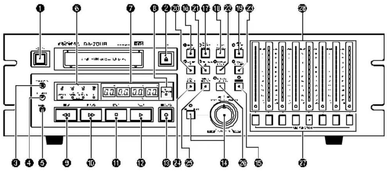
① Power switch
Turns the power to the DA-78HR on and off. When the DA-78HR is turned off, settings will be retained in memory.
② Tape loading slot and EJECT key
Only use Hi8 ME or MP tapes as specified in 1.5, "Recommended tapes". The DA-78HR will automatically eject all other tapes.
NOTE
Do not use a tape which has been used for recording video. Always use either new tapes or tapes which have been used in a DTRS recorder.
The EJECT key ejects any loaded cassette. A cassette can only be ejected when the transport is stopped.
③ FORMAT/Fs key
The FORMAT/Fs key controls the formatting of tapes and allows selection of the sampling frequency used for recording (see 5.1, “Formatting a tape” for full details). The current sampling frequency is shown on the status indicators ^6 .
④ HR MODE key
This key allows the selection of the recording resolution (16-bit or high-resolution 24-bit). See 5.1, “Formatting a tape” for details.
The appropriate indicator ⑥ will light if the HR mode is selected.
⑤ CLOCK key
This is used to select the word sync source for the DA-78HR (either internal, WORD or DIGITAL IN as shown on the indicated).
⑥ Status indicators
The status indicators show the current status of various DA-78HR functions. The legends of these indicators are abbreviated for reasons of space. Here is a list of their full meanings, together with the pages on which the functions are more fully described:
| Legend Meaning Section | ||
| HR | High-resolution (24-bit) mode 5.1 | |
| Fs (44.1k) | Either of these will light to show the current sampling frequency | 5.1 |
| Fs (48k) | ||
| ABS | Tape subcode (ABS) is being used as the timing reference | 9.1 |
| Legend Meaning Section | ||
| OFFSET | Machine or timecode offset is in operation | 8.3.1 and 9.6.2 |
| CLOCK (WORD) | When both of these are lit, the DA-78HR is using internal word sync, and when neither is lit, word sync is being received through the REMOTE IN/SYNC IN connector. If one is lit, the word sync is being received through the appropriate connector (digital audio (COAXIAL) or word sync). | 3.2 |
| CLOCK (DIGITAL IN) | ||
| TAPE TC | Lights when the DA-78HR is reading timecode from the tape | 9 |
⑦ Tape counter
The tape counter gives the current tape time in hours, minutes, seconds and frames.
It is also used to display menus, sub-menus and the values of the parameters of the unit, as well as providing information on the current status of the unit.
⑧ PB CONDITION indicator
There is one more indicator PB CONDITION which lights if there are many errors when reading or recording the tape. It also flashes when the block error rate is being checked (11.1.2, “Checking error rates”).
If this lights frequently, the block error rate can be checked and the heads cleaned (11.1, "Head and transport cleaning").
2.2 Tape transport keys and controls
⑨ REW key
Rewinds the tape at high speed.
If this key is pressed during recording, recording will stop and the tape will rewind.
⑩ F FWD key
Winds the tape forward at high speed.
If this key is pressed during recording, recording will stop and the tape will wind forward.
NOTE
When either REW or F FWD is pressed for the first time after powering up, or loading a tape, the unit first configures itself for the reel hub diameter of the tape in use, during which the tape advances at low speeds. This takes several seconds. Thereafter, the
transport momentarily goes into stop mode before the tape starts fast-winding.
⑪ STOP key
Cancels any current tape transport mode, and stops the tape. If pressed in chase mode, cancels the mode and stops the tape.
⑫ PLAY key
Starts playing the tape. If this key pressed while recording is in progress, the DA-78HR drops out of record mode.
13 RECORD key
If the PLAY key 12 is pressed while the RECORD key is held down, recording will start on all “armed” tracks (5.2.1, “Preparing to record”).
If the DA-78HR is in play mode, and thREC key is pressed, recording will start immediately on any “armed” tracks.
The RECORD key also is used to set punch-in points during auto punch-in/out operations (5.6, “Punch-in and punch-out”).
14 DATA/LEVEL control
When the SHUTTLE/DATA key is pressed, the indicator will light. The DATA/LEVEL control will then be active as a shuttle control. Turning the control to the right provides forward cueing and turning it to the left provides reverse cueing, similar to “rock and roll” on open-reel tape decks. For details, see 7.7, “Shuttle operations”.
When the SHUTTLE/DATA key is pressed in conjunction with the SHIFT key, the DATA/LEVEL control is also used as a data entry control to make various settings, including the sub-mixer settings. See 4.3.7, "Using the DATA/LEVEL knob to set values" and 7.4, "Sub-mixer" for details.
2.3 System control keys
The following keys all provide access to more advanced functions of the DA-78HR. Many of them are also used in the menu system to view and set system parameters. See 4, “Menu interface, etc.” for details.
Many of them also serve two functions, as shown by the blue “shifted” legends below the unshifted legends (shown here in parentheses). See 4.2, “The SHIFT key” for details.
⑮ SHIFT key and indicator
Controls the behavior of the other keys (see 4.2, “The SHIFT key” for details).
16 RHSL (DELAY) key and indicator
This key and indicator allow selection of the rehearsal mode in auto punch-in and out (5.6, "Punch-in and punch-out").
When the DA-78HR is in shift mode, this key allows the setting of track delays (7.3, "Track delay").
⑰ AUTO IN/OUT (OFFSET) key and indicator
This key and indicator allow automatic punch-in and punch out following rehearsal (5.6, “Punch-in and punch-out”).
When the DA-78HR is in shift mode, this key allows the setting of chase offsets (8.3, “Machine offset” and 9.6.2, “Timecode offset”).
18 CLEAR (PRE ROLL) key
This key defeats the rehearsal and auto modes during auto punch-in and out (see 5.6, “Punch-in and punch-out”). It can also be used to cancel a format operation (5.1, “Formatting a tape”).
When the DA-78HR is in shift mode, this is used to set pre- and post-roll times (5.6.4, “Editing the pre-roll and post-roll times” and 7.1.3, “Setting the location pre-roll time”).
⑲ VARI SPEED / PITCH key and indicator
Used to set the varispeed (pitch) amount, and to turn the function on and off (see 7.6, “Vari speed (pitch control)”.
20 ALL INPUT (▼) key and indicator
This key is used to switch the monitoring mode so that the outputs mirror the inputs (see 6.1, “ALL INPUT”).
② AUTO MON ( ▲) key and indicator
This key is used to change the monitoring mode to change automatically in punch operations (see 6.2, "AUTO MON").
In menu mode and when editing parameters, this acts as a key to select and change (increment) parameters.
When used with the SHIFT key, it acts as a cursor key.
2 - Front and rear panel features
②2 REPEAT (MENU) key and indicator
This key is used to provide a repeat function between the two location points (see 7.2, “Repeat function”).
When the DA-78HR is shift mode, it allows selection of the top-level menus (see 4.3, “Menus and sub-menus”).
②3 CHASE (SUB MENU) key and indicator
This key is used to set the DA-78HR to a slave chase mode, either to another DTRS unit, or to timecode (see 8.2.3, “Master/slave settings (CHASE mode)” and 9.6, “Chasing to timecode”).
When the DA-78HR is in shift mode, it allows selection of the second level of menus in the menu tree (see 4.3, “Menus and sub-menus”).
24 LOC 1 (MEMO 1) key
This key locates the tape to the position set by MEMO 1 (this key used with the SHIFTkey). See 7.1, "Autolocation" for details.
⑲ LOC 2 (MEMO 2) key
This key locates the tape to the position set by MEMO 2 (this key used with the SHIFT key). See 7.1, "Autolocation" for details.
26 MIXDOWN (LEVEL/PAN) key and indicator
This key turns the 8 x 2 sub-mixer output on and off from the rear panel outputs. See 7.4, “Sub-mixer” for details.
When the DA-78HR is in shift mode, this key is used to set the level and the pan position of each track in the sub-mixer image (7.4, "Sub-mixer").
2.4 Track controls
27 REC FUNCTION keys and indicators
These eight switches and indicators allow the setting and viewing of the record status on a track-by-track basis.
When one of these switches is pressed, the appropriate indicator will flash, the track is “armed”, and going into record mode will start recording on that track. When recording is being carried out on a track, the track’s indicator will light steadily.
In addition, these keys are also used to select tracks and channels for different operations, including the input and output patchbays, the delay and sub-mixer
functions. See 7.3, “Track delay”, 7.4, “Sub-mixer” and 5.3, “Input selection” for details of these operations.
28 Peak meters
These 15-segment peak meters show the input level or the recorded signal level, depending on the monitoring mode currently in operation (6, "Monitoring").
NOTE
When using digital recording equipment, there is no headroom above the 0 dB mark and no tape saturation is possible. Any signal which causes the "OVER" segment to light will cause audible distortion. For this reason you should take care not to let recording levels exceed this level.
The ballistics and peak hold times are selectable (see 7.8, “Meter modes”).
They may also be used to provide a quick visual guide to the status of some of the settings (sub-mixer, patchbay, etc.). See 4.1.1, “Peak meters” for details.
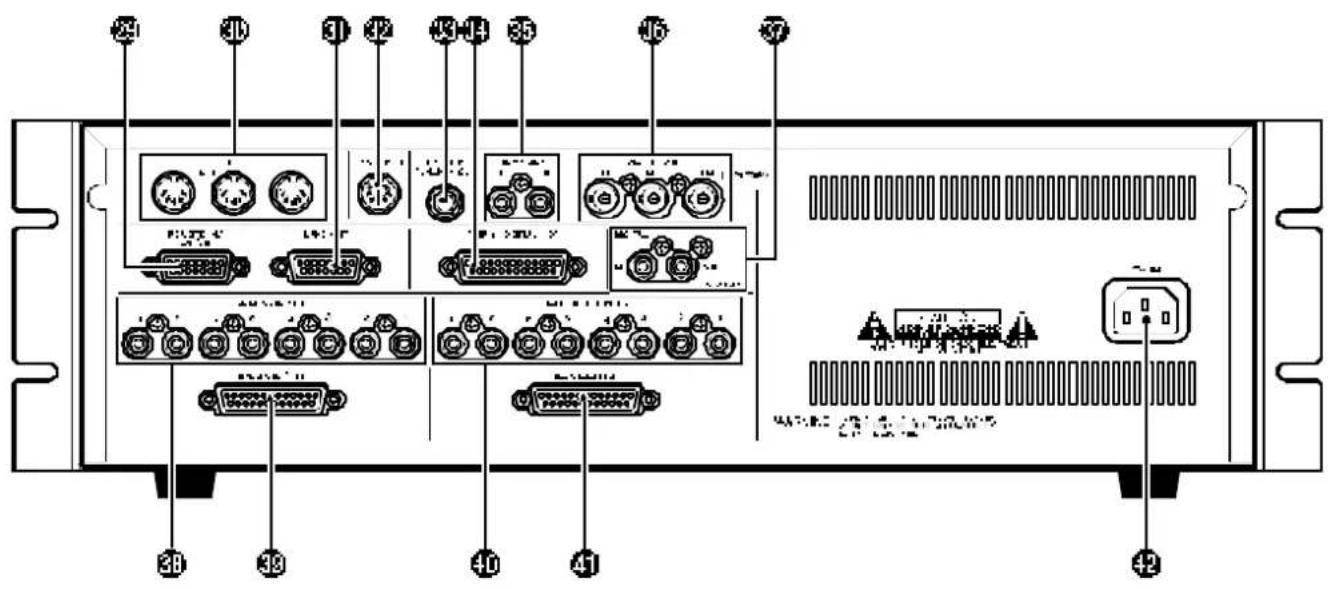
2.5 Rear panel features
See 3, “Connections” for full details of how to connect the DA-78HR to other units.
29 REMOTE IN/SYNC IN
This connector is used to connect another “master” DTRS unit (e.g. DA-78HR, DA-98, DA-88 or DA-38). See 8, “Synchronization with other DTRS units” for further details.
A TASCAM remote control unit may also be connected here, but not all functions of the DA-78HR may be available from the remote control unit.
30 MIDI IN/OUT/THRU
These connectors carry MIDI Time Code (MTC) and MMC (MIDI Machine Control) commands as well as MIDI System Exclusive messages. See 10, “MIDI control” for details of how these facilities are used when synchronizing to other units.
31 SYNC OUT
This is used to connect another DTRS unit in the “daisy-chain” or, if this DA-78HR is the last unit in the chain, to attach a termination plug.
32 REMOTE IN
Use this to connect an optional RC-808 remote control unit. Note that not all features of the DA-78HR can be controlled using the RC-808.
33 REMOTE PUNCH IN/OUT
Use this to connect an optional RC-30P foot-switch to control punch operations.
34 TDIF-1 (DIGITAL I/O)
This connector carries the digital signals to and from the DA-78HR in TEAC Digital Interface Format (TDIF-1).
35 TIME CODE (IN, OUT)
These RCA connectors are used to carry SMPTE/EBU timecode to and from the DA-78HR. For details of using the DA-78HR with timecode synchronization, see 9, “Operations related to timecode”.
36 WORD SYNC (IN, OUT, THRU)
These BNC connectors are used to carry the word clock between the DA-78HR and other types of digital audio equipment. The THRU connector is auto-terminated (i.e. there is no need for a terminator when this is unconnected).
37 DIGITAL IN, OUT (COAXIAL)
These RCA connectors provide an SPDIF stereo digital audio signal containing the submix signal(QU) or accept an SPDIF signal (IN) for recording (see 7.4, "Sub-mixer" and 5.3.1, "Digital input selection").
38 ANALOG INPUTS (unbalanced)
These eight RCA connectors accept unbalanced analog audio inputs at -10 dBV.
39 ANALOG INPUTS (BALANCED)
This connector carries 8 balanced inputs at a nominal +4 dBu level. This allows convenient and reliable single-cable connection to the GROUP outputs of a suitably-equipped console such as the TASCAM M-1600 series.
40 ANALOG OUTPUTS (unbalanced)
These eight RCA connectors output unbalanced analog audio signals at a -10 dBV level.
④1 ANALOG OUTPUTS (BALANCED)
This connector carries 8 balanced outputs at a nominal +4 dBu level. This allows convenient and reliable single-cable connection to the tape return inputs of a suitably-equipped console such as the TASCAM M-1600 series.
42 \~ IN
Use the provided AC power cord to connect the DA-78HR to the AC power supply through this connector.
This section explains how to connect other equipment to the DA-78HR. It is not intended as a complete reference to the use of the DA-78HR. See the appropriate sections for full details of how these connectors are used.
NOTE
When making connections between the DA-78HR and other equipment, whether audio or control, both the DA-78HR and the other equipment must be turned off, otherwise damage may be caused to the DA-78HR and/or the other equipment.
Only use TASCAM-supplied and TASCAM-approved cables when making connections to the DA-78HR. Though the cables and connectors may resemble computer cables, they serve different purposes, and meet a different set of specifications. The use of cables other than TASCAM cables will at best cause the equipment to work erratically, and at worst cause damage to the equipment.
If the use of cables other than TASCAM cables causes or results in damage, the warranty is voided.
3.1 Audio connections
Other audio equipment can be connected to the DA-78HR either using analog or digital interfaces.
Selection for the input source (analog or digital) on a global or individual track basis is made from the menus. See 5.3, "Input selection" for details.
3.1.1 Balanced analog audio connections
All balanced analog input and output audio connections to the DA-78HR are made through 25-pin D-sub connectors.
All these audio inputs and outputs are balanced and are rated at a nominal +4dBu level.
This allows convenient and tidy cabling between the DA-78HR and other units such as the TASCAM M-1600 series of mixing consoles.
It is not recommended that you make up your own cables—consult your TASCAM dealer for availability of suitable ready-made cables (and see 12.1.8, "Cables"). However, we recognize that every situation has its own unique features, and there are occasions when a special cable must be made.
Before starting to make the cable, we suggest you contact your TASCAM dealer for full details of cable specifications, etc.
The pinouts for both the ANALOG OUTPUT and INPUT connectors are as follows:
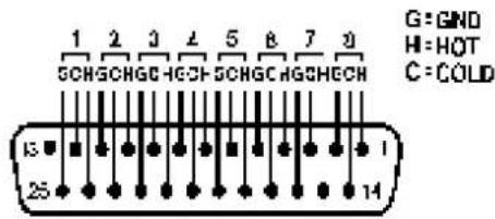
where G=ground, H="hot" (+) and C="cold" (-).
The impedance of the inputs is 20k and that of the outputs is 10 .
3.1.2 Unbalanced analog audio connections
In addition to the balanced analog set of connections, there are eight RCA jacks for input signals and eight for output. These are, of course, unbalanced, and the nominal signal level is -10 dBV.
NOTE
Only connect and use one set of analog inputs at a time. There is no facility to switch between the two sets of analog input connectors.
3.1.3 Digital audio connections
Multitrack digital audio input and output signals are carried on a single 25-pin D-sub connector. The signals are in TDIF-1 format.
To carry signals between a DA-78HR and another unit equipped with TDIF-1 interfaces, such as the TASCAM series of digital mixing consoles or other DTRS recorders, use a PW-88D cable (1 meter long) or a PW-88DL cable (5 meters long).
If you need to connect the DA-78HR to a digital audio source using a different format, we recommend the use of the following units:
- TASCAM IF-88AE Interface Unit—converts between the TDIF-1 and AES/EBU formats (8 channels). It also provides SPDIF format conversion facilities.
- TASCAM IF-AE8—also provides sophisticated conversion facilities between the TDIF-1 and AES/EBU data formats.
- TASCAM IF-88SD Interface Unit—converts between the TDIF-1 and SDIF-2 digital audio formats.
- The TASCAM IF-TAD—converts between the TDIF-1 and ADAT data formats, using a digital optical input/output for the ADAT data.
3 - Connections
3.1.4 SPDIF connectors
The coaxial RCA digital audio connectors on the rear panel allow connection of an SPDIF-equipped device (e.g. a DAT recorder).
This digital unit should be used as a clock source if data is to be read from it
When synchronizing to the signal received at the COAXIAL DIGITAL IN, set the CLOCK key so that the DIGITAL IN indicator lights.
3.2 Synchronization connections
The DA-78HR has facilities for control and synchronization with other units. For full details of how to operate the DA-78HR with other units, see 8, “Synchronization with other DTRS units” and 9, “Operations related to timecode”.
3.2.1 Word clock connections
This set of BNC connectors is used to synchronize the DA-78HR to other digital audio devices.
The CLOCK key is used to change between clock sources, and should be set tWORD when synchronizing to an external word clock (the WORD indicator will light).
The IN jack should be connected to the WORD SYNC OUT of the digital audio device from which the DA-78HR is to receive the synchronization clock.
The OUT outputs word clock information provided from the DA-78HR, while the THRU, to echoes the signals received at IN.
Note that if the DA-78HR is connected to other DTRS units, the WORD SYNC jacks do not need to be connected between the DTRS units.
3.2.2 MIDI connectors (IN, OUT and THRU)
These standard 5-pin DIN MIDI connectors are used to carry MIDI Time Code (MTC) and MIDI Machine Control (MMC) information between the DA-78HR and other suitably-equipped units (for instance, sequencers capable of being synchronized to MTC, and capable of transmitting MMC commands).
The MIDI parameters are set through the menu system (see 10, “MIDI control”).
Note the difference between MIDI OUT and MIDI THRU. The OUT connector outputs signals which originate from the DA-78HR. The THRU connector echoes messages received at the IN.
3.2.3 Timecode connections
The DA-78HR can be synchronized to externally-generated timecode and is also equipped with an internal timecode generator.
SMPTE/EBU timecode can be received at the TIME CODE INRCA jack, and can be transmitted from the TIME CODE OUT RCA jack.
See 9, “Operations related to timecode” for details.
3.2.4 MIDI timecode connections
The three MIDI connectors, IN, OUT and THRU, conform to the MIDI standards for such connectors.
3.3 Connection to other TASCAM units
By a “TASCAM unit”, we mean another DA-78HR, a DA-98, DA-88 or a DA-38 unit, or an optional remote control unit, which may also be connected in a “chain” with multiple DTRS units.
3.3.1 REMOTE IN
This jack on the rear panel can be used to connect a remote control unit such as RC-808 remote control unit.
Basic control can be carried out using this unit, but more advanced operations will not be possible.
3.3.2 Footswitch
A footswitch such as the optional TASCAM RC-30P footswitch can be connected to the REMOTE PUNCH IN/OUT jack on the rear panel.
This footswitch allows hands-free punch-in and punch-out.
When a track or track is armed, and the unit is in play mode, pressing the footswitch once will drop the unit into record mode, and pressing it again will drop it back into play mode.
The footswitch, rather than the transport keys, can also be used to set punch points, as described in 5.6, "Punch-in and punch-out".
3.3.3 Multiple DTRS units
Use a TASCAM PW-88S cable when connecting other units to the REMOTE/SYNC IN connector or to the SYNC OUT connector.
This synchronization cable will carry the internal synchronization code and the transport signals, etc. There is no need to make any other connections,
apart from the audio connections (either digital or analog).
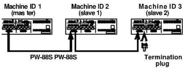
If more than one DTRS unit is to be used, the first unit in the chain must have its Machine ID set to "1", ("0" in the case of DA-88s) and subsequent units must have their IDs set in order with no gaps in the numbering sequence. Note that the diagram below does not show any audio connections.
flowchart
graph TD
    A["Machine ID 1 (mas ter)"] --> B["PW-88S"]
    C["Machine ID 2 (slave 1)"] --> D["PW-88S"]
    E["Machine ID 3 (slave 2)"] --> F["Termination plug"]
    B --> D
    D --> F
See 8.2, "Machine ID and master/slave settings" for details of setting the Machine ID using the menu system
NOTE
The last unit in the chain must be terminated (a TASCAM termination plug must be plugged into the SYNC OUT of the last machine in the chain. Once again, only use TASCAM cables for connection of equipment to and from the DA-78HR.
3.3.4 "Indirect" word sync
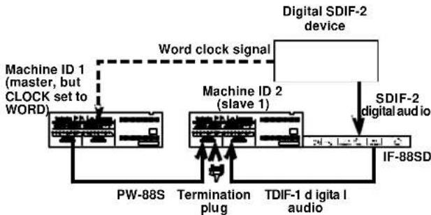
As mentioned earlier, there is usually no need to use a word clock when connecting DTRS units together. There is, however, an occasion when it is necessary to carry external word sync between DTRS units.
This is when a slave DTRS unit is recording digitally from another digital audio device:
flowchart
graph TD
    A["Machine ID 1 (master, but CLOCK set to WORD)"] -->|Word clock signal| B["Machine ID 2 (slave 1)"]
    B --> C["TDIF-1 d igital I audio"]
    C --> D["IF-88SD"]
    E["Digital SDIF-2 device"] -->|Word clock signal| B
    F["SDIF-2 digital audio"] -->|Word clock signal| B
    G["PW-88S"] --> A
    H["Termination plug"] --> B
Though the slave will receive its word clock from the master unit, the master itself must receive its word clock from the other digital audio device.
In this case, the master unit will have its clock source set to WORD, and the slave will receive its clock from the master unit through the SYNC IN.
4 - Menu interface, etc.
Read this section to understand the basic principles of the menu operations. These menus are used for making settings which cannot be made directly from dedicated front panel keys.
In addition, this section gives a brief description of the top-level menu groups as well as the sub-menu items and the parameters. This is not a detailed description of these menus and parameters, but may be consulted for quick reference. See the appropriate sections of the manual for detailed information regarding these menu settings.
4.1 The display
The DA-78HR's menus and their options are displayed using the time counter. Since the display is composed of 7-segment LED counters, a special alphabet is used to show the letters of the alphabet.
The characters on the DA-78HR time counter are shown as in the table below:
| A | B | C | D | E | F | G | H | I | J | K |
| b | c | d | E | F | G | H | i | j | ||
| L | M | N | O | P | Q | R | S | T | U | V |
| L | n | o | P | q | r | S | t | u | ||
| W | X | Y | Z | 0 | 1 | 2 | 3 | 4 | 5 | 6 |
| y | ||||||||||
| 7 | 8 | 9 | - | . | x^a | |||||
| - | . | |||||||||
a. This is a lowercase "x", used to denote an unknown value.
When a menu item or a value is given in this manual, we show it in the following way:
PE. HLD (PK HLD).
Notice also that because there are not many character positions on the time counter, the English menu titles, etc. may be abbreviated sometimes.
4.1.1 Peak meters
In addition to the time display, the bargraph meters are sometimes used to show a value. For example, in the stereo sub-mixer settings, the meters act as a bargraph display to show the “fader” settings of the track levels.
Typically, the higher the value of the parameter, the more segments of the meter are lit (at minimum values, no segments are lit, at maximum values, all segments are lit).
Pressing and holding SHIFT and pressing any REC FUNCTION key in these editing modes will toggle the meters between data value display and the normal meter display.
4.2 The SHIFT key
The SHIFT key serves two functions: first, to modify the action of another key when the SHIFT key is pressed and held while the other key is pressed, and secondly, to enter “shift mode”. These two are explained below.
4.2.1 Shifted keys
Some keys of the DA-78HR perform two functions, labels associated with the key. For instance, the LOC 1 (locate to memory position 1) key, has the alternative “shifted” function marked as MEMO 1 (store the current time into memory location 1).
When the SHIFT key is pressed and held down, and one of these keys, as described in the relevant part of this manual, is pressed, the shifted function will be performed.
The two keys can then be released in either order (either the SHIFTkey or the other key can be released first).
4.2.2 Shift mode
By contrast, pressing tSHIFTkey alone and releasing it will place the unit into "shift mode". The SHIFTindicator flashes to show this.
Pressing any of the two-function keys while the unit is in shift mode will automatically enter the shifted function.
While the unit is in shift mode, pressing the SHIFT key once again will turn the indicator off and exit SHIFTmode.
Note, however, that pressing and holding the SHIFT key and pressing another key to access the shifted function of that key will not affect the current shift mode.
4.3 Menus and sub-menus
When the unit is in shift mode, the REPEAT(MENU) key is the “gateway” to the menus. This key is used to show the top level groups of the menu tree:
| SYSTEN-- | SYSTEM-- | Basic system parameters and functions |
| Audio.1-- | AUDIO1-- | Parameters affecting the audio functions of the DA-78HR |
| Audio.2-- | AUDIO2-- | Additional audio features |
| tc-- | TC-- | Timecode parameters (generator, display, etc.) |
| tc.chs-- | TC.CHS-- | Parameters affecting the time-code chase mode of the DA-78HR |
| tcG.rEc-- | TCG.REC-- | Timecode generator recording parameters) |
| n_id-- | MIDI-- | Parameters concerned with the MIDI functions of the DA-78HR |
| nR.intn-- | MAINTN-- | Maintenance, etc. parameters, concerned with the DA-78HR |
When the MENU key is pressed, one of this group names is displayed on the screen and the unit enters menu mode. When the MENU key is pressed again, the next menu group name in this list above is shown (the list is “circular”, i.e. the first group name follows the last in the list).
Pressing and holding down the SHIFT key and pressing the MENU key goes to the previous menu group, following the order described above. Once again, the list is regarded as “circular”.
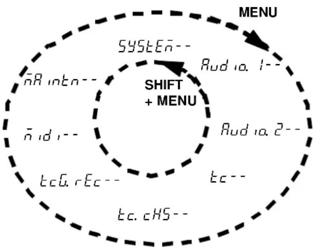
flowchart
graph TD
    A["SYSTEM"] --> B["Shift + MENU"]
    B --> C["MENU"]
    A --> D["na intn"]
    A --> E["na d"]
    B --> F["tcG.rEc"]
    B --> G["tc.cHS"]
    C --> H["Rud ia. 1--"]
    C --> I["Rud ia. 2--"]
    C --> J["tc--"]
Note that the titles of these top-level menu groups are all followed by two dashes ( ^- ), showing that there are submenus “under” this level.
4.3.1 Exiting menu mode
To exit menu mode, either:
- turn off the shift mode (press the SHIFT key so that its indicator is no longer flashing)
or
- enter another shifted function (except for the shifted MENU or SUB MENU functions)
4.3.2 Sub-menus
When a menu is displayed, pressing the shifted CHASE key (SUB MENU) brings up the sub-menu items associated with that particular top-level menu group.
There are two different ways of displaying sub-menu items:
- one is that the name of the parameter to be adjusted, and the current value of the parameter are displayed together.
- the other way is to that the name of the parameter is displayed for one second, and the display then changes to the current value of the parameter (this is when the parameter name and/or the value are too long to be displayed together).
Pressing the SUB MENU key cycles through the list of sub-menu items in a top-level menu group (the list is regarded as circular).
Pressing and holding the SHIFT key and pressing the SUB MENU key cycles through the sub-menu items in the reverse order.
4.3.3 Adjusting parameter values
In menu mode, the AU TO MON and the ALL INPUT keys perform the function of up and down keys (▲ and ▼) and they are used to change the values of parameters in the sub-menu items.
As soon as the value of the parameter is changed on the display, the parameter itself is changed (i.e. there is no need to confirm changes with an ENTER key or the equivalent).
If one of these keys is pressed and held down for half a second, the key changes to a “repeat” mode. If the key is held down for one second, the repeat mode changes to a “fast repeat” mode, and the value of the parameter changes faster.
4.3.4 Resetting parameters to default values
To reset a parameter value to the default value, press and hold down the ▲ key and immediately afterwards, press the ▼ key, or vice versa.
4.3.5 "Left" and "right" keys
When editing time values, etc. it is useful to be able to edit one particular element (i.e. hours, minutes, seconds or frames) of the time value.
The “cursor” is indicated by a flashing dot following the “field” currently being edited.
There are no dedicated left and right cursor keys. Instead, when the unit is in menu mode, pressing and holding the SHIFT key and pressing the ▲ key will have the effect of a left cursor key.
Likewise, pressing and holding the SHIFT key and pressing the ▼ key will have the effect of a right cursor key.
It should be noted that there is an “invisible” field to the right of the frames field. This allows the whole of the displayed value to be incremented, not just the highlighted field. In other words, frame values, etc. will “roll over” and increment the next field to the left. In this mode, there is no flashing dot to indicate the cursor.
Repeated presses of these keys will allow the editing of the following fields (in order):
Hours Minutes Seconds Frames Frames (with increment of whole time value) Sub-frames percentage Sub-frames percentage (with increment of whole time value) Sub-frames samples Sub-frames samples (with increment of whole time value) Hours, etc.
The right “cursor key” (SHIFT + ▼) moves forward through the list, and the right “cursor” key (SHIFT + ▲) moves backward.
The sub-frame displays (in italics above) are explained in the section below (4.3.6, “Sub-frame values”).
4.3.6 Sub-frame values
There are two ways of representing sub-frame values: as “percentage” subframes, or as samples.
When sub-frames are displayed as percentages, the minimum displayed value is always 00 and the maximum displayed value is 99.
When displayed as a sample value, the number of samples per frame varies, according to both the sampling rate, and the frame rate currently selected:
| Sampling frequency → rate ↓ | 48 kHz 44.1 kHz | |
| 24 | 1999 | 1469 |
| 25 | 1919 | 1763 |
| 29.97 | 1601 | 1471 |
| 30 | 1599 | 1469 |
| ABS | 1439 | 1322 |
When moving around a time value in the way described above, moving the “cursor” past the frames field will change the display to a sub-frame display.
A sub-frame display shows SF (SF), followed by either the 2-digit representation of the percentage subframe value SF or the 4-digit representation of the sample value SF
There are four modes of sub-frame display:
• Percentage
• Percentage with increment of whole time value
- Samples
• Samples with increment of whole time value
In the two display modes where there is an increment of the whole time value, there is no dot displayed.
These modes are accessed, as explained above (4.3.5, ““Left” and “right” keys”) using the “cursor keys”.
To return to the hh:mm:ss.ff display, move the cursor “outside the display”, i.e. to the right of the sub-frame field when the “samples with increment of whole time value” mode is displayed.
4.3.7 Using the DATA/LEVEL knob to set values
In some menus and other parameter settings, it is possible to use the DATA/LEVEL knob to set numerical values.
1 Press and hold down the SHIFT key, and press the SHUTTLE/DATA key.
This data setting is the default setting, made at power-up.
2 When editing the value of a parameter, and the SHUTTLE/DATA indicator is blinking slowly,
4 - Menu interface, etc.
the current position of the knob and the current parameter value do not match.
3 When the SHUTTLE/DATAindicator knob blinks rapidly, the current position of the knob matches the current parameter value. Turning the knob from this position will now allow the parameter value to be changed.
4 Turn off the “data entry” mode using the SHIFT and SHUTTLE/DATAkey combination.
Until the match described above has been made, the value of the parameter cannot be changed using the knob.
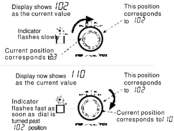
Note that because of the precision of the knob, the value may sometimes appear to “jump”.
Fine-tuning of values should be done with the ▲ and ▼ keys.
4.4 SYSTEM menu
SYSTEM-- The following parameters are used to control and provide information regarding the overall operation of the unit:
| Display | Values (*=default) | Described in |
| id. SEL.(ID selection) | 1*through 15 | 8.2. 2, “Setting machine ID” |
| ID when the unit is connected in a chain of DTRS units | ||
| t inE. node.(time mode) | Rb5*,tc | 9.1, “ABS and timecode” |
| Reference timing source | ||
| clock node(clock mode) | Ruto*,indu id(individual) | 8.6, “Individual clock mode” |
| Clock source for a slave unit. | ||
| Display | Values (*=default) | Described in |
| PE.HLD(peak hold) | 0, 1 through8 seconds (default is 3), cnt (continuous) | 7.8.1, “Peak hold time” |
| Meter peak hold time | ||
| rLS(release time) | FRSE*, SLOB(slow), ñEd(medium) | 7.8.2, “Meter ballistics” |
| Meter release time | ||
| SRE.E.(save) | oFF* 7.14, “Saving settings to tape” | |
| Saves the current settings to the tape | ||
| LoRd(load) | oFF* | 7.15, “Restoring settings from tape” |
| Loads settings from tape | ||
4.5 AUDIO1 menu
Audio. 1. -- The following parameters are used to control the audio operation of the unit using the first audio menu:
| Display | Values (*=default) | Described in |
| d. in. | td,IF (TDIF)^* , SPD (SPDIF) | 5.3.1, “Digital input selection” |
| Selects digital audio source (for tracks 7 and 8 only) | ||
| in. PRtch (input patch) | ALL. AnRLG* (all analog), ALL. dGEL (all digital), individual track s set to R0 (ana-log), d0 (digital) or t0 (track) | 5.3, “Input selec-tion” |
| Track input source can be either analog, digital or a recorded track | ||
| td. IF. (TDIF) | 24*, 20, 16 | 5.4.2, “Selecting input word length” |
| Input digital word length | ||
| d. tH (dither) | off*, rEct (rect-angular), tr (tri-angular) | 7.11.1, “Selecting dither settings” |
| Dither noise shape | ||
| rEc.nute. (rec mute) | ALL off. *,ALL on or individual tracks on or off | 7.10, “REC MUTE (recording silence) |
| Rec mute function | ||
4.6 AUDIO2 menu
Audio.2.-- This menu provides additional audio parameter settings:
| Display | Values (*=default) | Described in |
| c. FRdE. (crossfade) | 10* through 200 (in 10 ms increments) | 7.5, “Crossfade times” |
| Crossfade time for punch, etc. | ||
| out.PRTch (output patching) | norRL* (normal or as set) | 7.12.2, “Output patchbay” |
| Output patchbay | ||
| out.bvt. (output word length) | 16,24* 7.12.1, “Output word length” | |
| (word length of digital output) | ||
| SHtL.non. (shuttle monitor) | 0 (off)*, 1 (on) 6.3, “Shuttle monitor” | |
| Shuttle monitor function | ||
| SHtL.nut. (shuttle mute) | 0 (off)*, 1 (on) 6.4, “Shuttle mut-ing” | |
| Shuttle mute function | ||
| o5c. (oscillator) | off*, 440, 12 (1k) | 7.9, “Sine oscillator” |
| Line-up oscillator | ||
4.7 TC menu
t c -- The following parameters are used to control timecode operations:
| Display | Values (*=default) | Described in |
| tRPE.tc (tape TC) | tc trP* (TC track), conū (converted), Rb5 (absolute) | 9.2, “Tape time-code mode” |
| Tape timecode source | ||
| Frā nodE (frame mode) | SYS8 (SYS), E4t (EXTERNAL), tRPE (TAPE): 29df*, 30nd, 29nd, 25, 24, 30df | 9.3, “Selecting the frame mode”, 9.4.1, “Showing input timecode”, 9.5.8, “Checking the frame mode of striped timecode” |
| System frame mode and external tape frame rate display | ||
| d, SP. (TC display) | tRPE* (off-tape), E4t (external), d, FF (difference) | 9.4.1, “Showing input timecode” |
| Timecode display source | ||
| in.tc.tēG (input TC timing) | RnALoG*, d, G, tRL | 9.4.2, “Timecode input timing” |
| Incoming timecode reference | ||
| out.tc.tēG (output TC timing) | RnALoG* (analog), d, G, tRL (digital) | 9.4.6, “Timecode output timing” |
| Outgoing timecode reference | ||
| out.tc.Src (output TC source) | tRPE tc* (from tape), rEGEn (regenerated), rESHAPE (reshaped) | 9.4.3, “Timecode output” |
| Source of outgoing timecode | ||
| FRSt Ltc (fast LTC) | S Frā* (5 frames), LEAP (leap)pFF | 9.4.5, “Fast linear timecode (LTC) output” |
| Fast LTC output mode | ||
4.8 TC chase menu
bc.cHS -- The following parameters are used to control the DA-78HR operations when chasing to an incoming timecode signal:
| Display | Values (*=default) | Described in |
| ind iū, rEc (individual recording) | 0* (off), 1 (on) 9.6 | 11, “Individual recording while chasing timecode” |
| Enabling individual recording while chasing | ||
| rEcHS. ōd (rechase mode) | rEcHASE* (rechase), FrEE (free) | 9.6. 9, “Rechasing timecode” |
| Rechase mode | ||
| rEcHS. yd (rechase window) | 15Ec*, 25Ec (1 or 2 seconds) | 9.6. 9, “Rechasing timecode” |
| Width of rechase “window” | ||
| Err. byPRS (error bypass) | 10 Frn*, 30 Frn (10 or 30 frames) | 9.6. 10, “Bypassing timecode errors” |
| Length of time for error bypass when chasing | ||
| Pb. Po5. tSE (park position test) | oFF*, on | 9.6. 6, “Park position” |
| Performs the park position test | ||
| PRtE. Po5. (park position) | 00 00* (0 seconds, 0 frames) to 01 29 (1 second, 29 frames) | 9.6.7, “Automatic park position setting” |
| Park position timing | ||
4.9 TC generator menu
E_cG. rE_c -- The following parameters are used to control the internal timecode generator.
| Display | Values (*=default) | Described in |
| tc. rEc. Src (TC recording source) | E4t* (external), tcG (TC generator), tRPE tc (tape timecode) | 9.5. 1, “Selecting the timecode source” |
| Selects the source of the timecode “stripe” | ||
| Display | Values (*=default) | Described in |
| tc. rEc. En (TC recording enable) | ^* (off), I (on) 9.5.2 | “Recording timecode using the generator” |
| Enabling of timecode recording | ||
| Strt. t inE (TC generator) | Time value in hh:mm:ss.ff (00:00:00.00*) | 9.5.2, “Recording timecode using the generator” |
| Start time for on-board generator | ||
| tcG. node (TC generator mode) | rESEt* (reset), cont (continue) | 9.5.3, “Generator modes” |
| Restart mode for on-board generator | ||
| tcG. (TC generator) | StoP* (stop), run (run) | 9.5.2, “Recording timecode using the generator” |
| Start/stop timecode generator | ||
4.10MIDI menu
id ^1-2 The following parameters are used to control the MIDI parameters of the DA-78HR.
| Display | Values (*=default) | Described in |
| id _1 (MIDI) | on*, oFF | 10.1, “MMC enable and disable” |
| Enables or disables MIDI (including MTC) | ||
| _id (MIDI ID) | ALL*, I to 127 | 10.1.1, “Assigning a MIDI ID to the DA-78HR” |
| MMC ID | ||
| tc(MTC) | on*, oFF | 9.4.4, “MTC output” |
| MTC output | ||
| FRSt. tc(fast MTC) | on*, oFF | 9.4.4, “MTC output” |
| MTC output in fast wind mode | ||
| Stop. tc(stop MTC) | on*, oFF | 9.4.4, “MTC output” |
| MTC output in stop mode | ||
4.11 Maintenance menu
into-- The following menu provides information relating to maintenance procedures, etc.
| Display | Values (*=default) | Described in |
| _ion (version) | 5y5 (system).*Front (front), 5uo (servo) | 11.3, “Checking version numbers” |
| System, front panel driver, servo software (f imware) versions | ||
| drun.t.in(drum time) | totL* (total),SrcH (search) | 11.1.3, “Checking drum time” |
| Number of hours the drum has been in use | ||
| cLEN(cleaning) | off* 11.1, “Head and transport cleaning” | |
| Starts the head cleaning process | ||
| b.E.r.(block error rate) | off*,on | 11.1.2, “Checking error rates” |
| Displays the current block error rate | ||
| init.(backup memory initialization) | off* 11.2, “Backup memory initializa-tion” | |
| dEütype(emulated device type) | dR-78Hr*, dR-88, dR-38, dR-98 | 7.13, “Emulation” |
4.12 Dedicated keys
The following (shifted) keys also allow settings to be made. These are fully described in the appropriate sections of the manual:
| Key Description | Description Described in | |
| DELAY | Individual relative track delay | 7.3, “Track delay” |
| OFFSET | Offset relative to timecode or absolute times | 8.3, “Machine offset” and 9.6.2, “Timecode of fset” |
| PREROLL | Locate pre-roll and auto-punch pre- and post-roll times | 5.6.4, “Editing the pre-roll and post-roll times” and 7.1.3, “Setting the location pre-roll time” |
| PITCH | Varispeed (±6.0%) | 7.6, “Varispeed (pitch control)” |
| LOC/MEMO 1 | Location memory points | 7.1, “Autolocation” |
| LOC/MEMO 2 |
This section explains some of the basic operations using the DA-78HR. Section 7, “Advanced operations” describes more advanced operations.
Most operations on a DA-78HR are similar to those on a traditional analog multitrack recorder, but we suggest that you read this section and the next to learn about the features of the DA-78HR.
5.1 Formatting a tape
Before you use a tape in the DA-78HR, you must first format it. This marks internal synchronization patterns for the servo to follow on subsequent passes through the tape as well as the subcode data (ABS).
The process also initializes the tape for recording at either 16-bit or 24-bit resolution.
No audio data is normally recorded during a formatting operation (but see below).
5.1.1 Selecting a word clock source
1 Use the CLOCK key to select a clock source.
NOTE
Remember that in your digital audio setup, only one digital audio device should be set to be a clock master. All other digital audio devices must derive their clocks from it.
There are four options available:
- WORD (the WORD indicator lights)—this is the word clock received at the WORD SYNC IN connector. You may use this setting when recording digital audio through the TDIF-1 input, if the source of the audio is set to be a clock master.
- INT (internal)—both the WORD and DIGITAL IN CLOCK indicators light. You may use this setting if other digital audio devices are to be word clock slaves, or if the input signals are analog.
- DIGITAL IN—this refers to the SPDIF(OAXIAL) input. Use this if the recording source is to be received here, and the source device is a word clock master.
- SYNC IN—this cannot be set using OeCK key, but occurs automatically when the DA-78HR is being controlled from another DTRS unit, and the REMOTE IN/SYNC IN connection has been made (see 8.1, “Synchronization connections”). Neither the WORD nor DIGITAL IN indicators will light at this time.
5.1.2 Formatting
While formatting is proceeding, you cannot perform any other transport operation except stopping the tape.
You cannot change the sampling rate or the bit resolution while formatting is in progress.
1 Switch on the DA-78HR and load a tape into the tape loading slot. As the tape is loaded and threaded, the tape counter shows
For details of tapes that you can use in the DA-78HR, see 1.5, "Recommended tapes".
2 PressREW to take the tape to the beginning and stop the tape.
3 Press the FORMAT/Fs key. The display shows Format (FORMAT).
4 Press the FORMAT/Fs key again within 5 seconds. The display will then show a flashing F, followed by all dashes (F - - - - - - - ).
If you do not press the FORMAT/Fs key twice within 5 seconds the Format message will disappear. This is a feature designed to stop you formatting a tape accidentally.
$$ " - L o R d - -". $$
NOTE
If you do press the FORMAT/Fsey twice and you then change your mind about formatting the tape, use either the CLEAR or STOP key to cancel the operation.
5 Select the sampling frequency (either 44.1kHz or 48kHz), using the FORMAT/Fs key.
The sampling frequency that you select depends on the eventual use for the recording. For audio work, selecting 44.1kHz will allow you to produce CD master tapes with no frequency conversion.
NOTE
If a digital signal is received at DIGITAL I/Ojack or at the SPDIF (COAXIAL) input, the DA-78HR's recording and playback sampling frequency is automatically determined by the sampling frequency of the input signal and you cannot change it.
6 Select the recording mode using theHR MODE key. When HR mode (24-bit recording) is selected, theHR indicator to the left of the time counter will light.
Remember that if HR mode is selected, the tape must be replayed on an HR DTRS
5 - Basic operations
recorder. Of course, a non-HR (16-bit) recording made on the DA-78HR can be replayed on any DTRS recorder.
7 To start formatting the tape, hold down the RECORDkey and press the PLAY key.
NOTE
The tape counter may show a negative ABS time for a short while at the start of the formatting process. While it is displaying a negative value, no audio recording can take place.
8 The tape will format to the end, and then rewind automatically.
You are now able to use the tape for recording.
All transport controls are disabled during formatting, except for the STOP key, which can be used to abort the format process.
It is possible to format tapes on a number of DTRS units simultaneously. For details, see 8.5, “Synchronized formatting”.
5.1.3 Aborting the format process
To abort the process before formatting actually takes place (i.e. you have pressed the FORMAT/Fs switch twice in error), press the CLEAR or the STOP key.
The only transport operation you can perform once formatting has started is to stop the tape.
However, we do not recommend interrupting the formatting process, but suggest that you let the tape run to the end.
If you interrupt the formatting (or the formatting is interrupted by a power cut or events beyond your control), rewind the tape and start the format from the beginning of the tape again.
5.1.4 Recording while formatting
If you have armed any tracks (you have pressed its REC FUNCTION switch, and the indicator is flashing), any audio signal routed to that track will be recorded while formatting is in progress.
NOTE
If you have recorded and formatted part of a tape, and you wish to continue formatting and recording on the rest of the tape ("assembly"), you should rewind to a pre-formatted, blank section of the tape and resume formatting and recording from there.
Recording and formatting will continue at the sampling frequency used on the first part of the tape.
Avoid re-starting recording and formatting from an unformatted section of the tape.
5.2 Recording the first tracks
There are a number of different ways of recording the first tracks. However, all follow the same basic principles.
- When using a newly-formatted tape, we suggest that you record a blank “leader” about 30 seconds long, starting from the beginning of the tape, to avoid dropout. Leave a similar recorded blank “trailer” at the end of the recording. You can use the Rec Mute function as a convenient way of recording silence. See 7.10, “REC MUTE (recording silence)”.
- If the tape counter shows a negative value, you cannot record on the tape at that position.
5.2.1 Preparing to record
1 If you have not already loaded a formatted blank tape, do so now.
2 Make sure that varispeed is turned off. Check the VARI SPEED indicator 7.6, "Vari speed (pitch control)".
3 Select the recording source (see 5.3, "Input selection") as either all digital, all analog or a mixture of these sources. The DA-78HR contains a "patch bay" which allows you to route inputs to tracks.
5.2.2 Selecting a clock source
1 If you have selected a digital source, you should select the word clock master using the CLOCK key.
This can either be an external word clock connected to the rear panel BNC WORD IN connector, or it can be the SPDIF (COAXIAL) digital audio signal. The appropriate indicator to the right of the time counter will light.
Alternatively, if both of these are lit, the unit will serve as the word clock master in the audio system.
NOTE
Remember that there must be one, and only one, word clock master unit in a digital audio system.
5.2.3 Write-protecting cassettes
You cannot record on a cassette where the write-protect tab has been closed (write-protected).
Hi8 cassette write tabs work in the opposite manner to DAT cassettes, and “closed” means “write-protect”.
If the tape is write-protected, eject the tape, open the write-protect tab, replace the cassette, and try again.
- Sony Hi8 cassettes (and those from some other manufacturers) have the words “SAVE” (write-protected) and “REC” (write-enabled) molded into the cassette shell by the protection tab.
5.2.4 Recording the first tracks (i)
1 Arm the tracks on which you wish to record.
Press the REC FUNCTION key of these tracks; the indicator will start flashing.
2 Adjust the input signal levels so that the track meters read high, but the OVER segment does not light.
3 Hold down the RECORD key, and press the PLAY key. The tape will start moving and recording will start.
The REC FUNCTION indicators of all armed tracks will light steadily.
When you start recording, the point at which recording starts is automatically stored into memory for punch-in purposes.
4 To stop recording and stop the tape, press the STOP key. You can also press the PLAY key, which will continue the tape movement, but stop recording.
5.2.5 Recording the basic tracks (ii)
This is an alternative method of recording basic tracks on a blank, formatted tape.
1 Arm the tracks and adjust the levels as described in [1] and [2] above (5.2.4, "Recording the first tracks (i)").
The REC FUNCTION indicators of all armed tracks will flash.
2 Press the PLAY key. The tape will start moving.
3 When you reach the point at which you want to start recording, press the RECORD key.
The REC FUNCTION indicators of all armed tracks will light steadily.
The point at which recording starts is automatically stored into memory for punch-in purposes.
4 Stop recording as described above.
5.2.6 Replaying the first tracks
When you have positioned the tape at the beginning of the recording you have just made (or at the pre-roll point), you can start playing back the tape.
1 Turn off the RECORD FUNCTION switch of the track you have just recorded (not compulsory, but recommended, as this will prevent you from accidentally hitting the RECORD key and going into record mode, overwriting what you have already recorded).
2 Rewind the tape to the point that you started recording and press PLAY.
5.3 Input selection
This section describes how to choose all analog or all digital input sources when recording with the DA-78HR. For other routing procedures, see below (5.3.2, "Input patchbay routing").
1 Press the SHIFT key so that the unit is in shift mode (SHIFT indicator is flashing).
2 Press the MENU key until the display shows Audio, I-- (AUDIO1--).
3 Press the SUB MENU key until the display briefly shows in.PATCH (IN PATCH) and then changes to the current setting.
4 To change between all analog and all digital inputs, press the ▲ and ▼ keys ALL RoALG (ALL ANALG – all analog) or ALL dGTL (ALL DGTL – all digital).
In the above two settings, the inputs are mapped to the tracks on a one-to-one basis (i.e. input 1 is routed to track 1, input 5 is routed to track 5, etc.).
5.3.1 Digital input selection
If 7 and 8 are selected for digital input, the d in (D IN) menu item allows you to choose between the TDIF-1 input and the SPDIF COAXIAL) input.
If the SPDIF (COAXIAL) input is selected, these signals ( d^7 and dB ) can then be routed to any track (see below, 5.3.2, “Input patchbay routing”).
NOTE
If the SPDIF COAXIAL ) input is selected, it is not possible to use the other six channels of the TDIF-1 digital input. It is, however, possible to record analog
5 - Basic operations
signals or to perform track-bounce operations with the SPDIF (COAXIAL) input selected.
Note that whatever digital source is selected, the appropriate clock must be selected. If you are recording from (say) a CD player, which typically cannot accept a word clock, as well as from a TDIF-1 source (e.g. a TASCAM digital mixer) the DA-78HR must be set to accept the clock from the DIGITAL IN(see 5.2.2, “Selecting a clock source”). This clock must then be sent from the THRU of the DA-78HR to the IN of the TDIF-1 device, which must be set as a word sync slave.
1 Press theSHIFTkey so that theSHIFTindicator is flashing, and press the MENU key until the display shows Aud 10. I-- (AUDIO1-).
2 Press theSUB MENU key until the display showsd. in (D IN) followed by the current setting.
3 Use the ▲ and ▼ keys to change between td , F(TDIF) and SPd (SPDIF—COAXIAL) .
NOTE
You cannot use the SPDIF (COAXIAL) output from the sub-mixer while accepting a signal from the SPDIF (COAXIAL) input.
You must use a tape formatted at the sampling frequency of this input (i.e. you cannot use the SPDIF (COAXIAL) input to record a CD on a 48kHz tape. Varispeed is also not possible when recording using this input.
5.3.2 Input patchbay routing
To route inputs to tracks whose numbers do not correspond to those of the inputs, or to mix the types of input source (digital, analog or off-tape):
1 Follow steps 1 through 3 in 5.3, "Input selection" above,
2 Press the REC FUNCTION key of the track to which the input will be routed.
3 The display changes to show the track number of the destination track, together with the source (e.g. E r P 1 R 1 (TRK1 A1) shows that track 1 has been selected, and that analog input 1 is the source.
4 Use the ▲ and ▼ keys to change the input source from R1 through R8 (analog 1 through 8), d1 through d8 (digital 1 through 8) and t1 through t8 (track 1 through 8).
5 To select another destination track, press that track's REC FUNCTION key and repeat the process.
NOTE
If your setting results in all tracks being fed on a one-to-one basis from the same input source (analog or digital), the display will change to show this, a few seconds after the patchbay operation that caused this to be the case.
| T 7/8 | The meters can be used to see the patchbay assignment using the meters, as shown here. Each meter gives the status of its correspondingly-numbered track. | |
| T 5/6 | ||
| T 3/4 | ||
| T 1/2 | ||
| D 7/8 | ||
| D 5/6 | PressSHIFT and one of the REC FUNCTION keys (as described in 4.1.1, “Peak meters”) to toggle this meter mode off and on. The default at power-on is for this mode to be on. | |
| D 3/4 | ||
| D 1/2 | ||
| A 7/8 | ||
| A 5/6 | ||
| A 3/4 | ||
| A 1/2 | ||
| Because of the limitations of the number of meter segments available, each segment is used to rep- |
resent two input possibilities. The top third is used to show track sources, the middle third is used for digital, and the lower third for analog sources.
With a digital recorder such as the DA-78HR, track crosstalk is almost negligible (better than 90dB at 1 kHz). For this reason, you do not have to worry so much about the constraints of choosing physical track locations as you do with analog recordings.
5.3.3 Track bouncing
If you need to copy a track to another track at any time in the recording process, remember that track copying in the digital domain will add no noise or distortion. A digital copy is a “clone” of the original, and no loss of quality is incurred.
The DA-78HR allows you to copy tracks digitally, and you can use the internal sub-mixer (see 7.4, "Sub-mixer") to combine all tracks (level and pan can be set) to tracks 7 and 8.
NOTE
Because the DA-78HR also allows a track to be replayed and recorded onto itself, all eight tracks can be mixed internally and merged into tracks 7 and 8.
The basic method for going about this is:
1 Exit shift mode and enter theMIXDOWN mode.
2 Enter shift mode, and enter the sub-mixer mode.
3 Make the level and pan settings for the tracks which are to be combined, as described in 7.4, "Sub-mixer". See this section for full details of how to operate the sub-mixer.
4 You can use the DA-78HR's SPDIF (COAXIA), TDIF-1 and analog outputs to monitor tracks 7 and 8. Only tracks 7 and 8 will be output from the TDIF-1 and analog outputs, and the other track outputs will be muted.
5 Arm tracks 7 and 8.
6 Record tracks 7 and 8.
5.3.4 Returning to ALL ANALOG setting
After tracks have been set individually, it may be necessary to return the inputs to all analog. It is then easy to return to all digital (see 5.3, “Input selection”), but setting all inputs to “all track” would be a somewhat pointless setting!
1 While the unit is in "patchbay" mode, as described in 5.3.2, "Input patchbay routing", press and hold down one of the ▲ or ▼ keys, and press the other of these keys.
The routing will change to all analog (ALL AnRLoG).
5.4 More on digital recording
The DA-78HR is able to accept (and output) digital signals at the DIGITAL I/O connector in TDIF-1 format.
The DA-78HR should be connected to other TDIF-1 equipment using a PW-88D or PW-88DL connector cable.
NOTE
Only use a TASCAM digital cable when making digital audio connections to the DA-78HR. Other types of cable may cause damage to the system, and the warranty will be voided if such damage is caused by use of the wrong cables.
The DA-78HR should be set to be either a word clock master or a word clock slave when connected to other digital equipment. There can only be one word clock master in a setup.
5.4.1 Sampling frequency and word length
If you attempt to record digitally from a digital source which has a different frequency from that previously recorded as the DA-78HR's tape format, the Fs indicator corresponding to the tape's sampling frequency will start to flash. This indicates a frequency mismatch.
Recording with different sampling frequencies is not recommended – problems will certainly occur on replay of such a recording.
If you attempt to record digitally from a digital source with a word length (5.1, “Formatting a tape”) different from that for which the tape has been formatted, errors will occur. A good rule is therefore to keep one word length and one sampling frequency throughout a tape.
5.4.2 Selecting input word length
When data is accepted through the DIGITAL I/O connector, the word length of the incoming data must be set. This can be selected from between 16-bit, 20-bit or 24-bit. This is not the same as the resolution recorded on tape.
To set the word length:
1 Press theSHIFT key so that the SHIFT indicator is flashing, and press the MENU key until the display shows Audio. 1-- (AUDIO1--).
2 Press the SUB MENU key until the display shows ed, F. 88 (TDIF xx, where xx is the current input word length).
3 Use the ▲ and ▼ keys to choose between 24, 20 and 16-bit word lengths.
We suggest that you experiment with the dither settings (7.11, “Dither”) if you find you are recording quantization noise at low levels when the input word length is set to 20 or 24 bits and you are recording at 16-bit resolution. Though you will lose a little in the signal-to-noise ratio, total harmonic distortion figures will be improved.
NOTE
If you are dubbing tracks from a DA-88, this value must always be set to 16 bits.
5.5 Overdubbing
Overdubbing subsequent tracks is carried out in a very similar way to recording the first tracks.
5 - Basic operations
If you are unsure about the difference between monitoring modes as implemented on the DA-78HR, now is a good time to read 6, “Monitoring”.
Obviously you will want to record while you listen to the off-tape signals from previously-recorded tracks and the input source on tracks where recording is taking place.
5.6 Punch-in and punch-out
There are a number of ways in which the DA-78HR can be used to perform reliable punch-in and punch-outs automatically. Punch points can be set and edited to frame accuracy, either from a cue list or “on-the-fly” in real time.
The DA-78HR provides a rehearsal mode which simulates the punching process, allowing the artists to perfect the timing of the new material.
The mechanics of punching on a digital recorder appear to the operator to be the same as on an analog recorder.
Crossfading, however, is an important and useful function on digital recorders, to ensure continuity between original and punched material. In the case of the DA-78HR, this crossfade time is adjustable from 10 milliseconds to 200 milliseconds (7.5, “Crossfade times”).
The AUTO MON mode is essential here: in both rehearsal and punch modes, the material prior to the punch point is monitored off tape. The monitoring of armed tracks changes to source while rehearsals and punching are carried out and then changes to off-tape again after the punch-out point See 6, “Monitoring” for details of monitoring modes, including the AUTO MON mode.
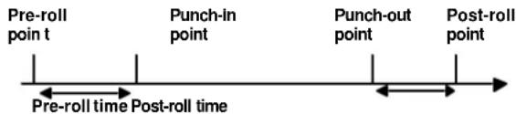
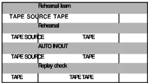
NOTE
Though it is possible to perform punch recording in ALL INPUT mode, the monitoring in this mode does not make it easy to perform accurate punch operations. We suggest that you turn this mode off when performing punch-ins.
5.6.1 Automatic punch point setting
Whenever recording takes place, the time when recording begins is automatically stored as a punch-in time, and the time when recording stops is stored as a punch-out time.
This is not usually the way in which you will want to set the punch points, however. There are several alternative ways in which you can set these points, as described below:
5.6.2 Setting punch points "on the fly"
This method demands sharp reflexes (but you can edit the punch points later as we show below).
NOTE
If an optional footswitch has been attached to the rear paneREMOTE PUNCH IN/OUT jack, this can be used in the following steps instead of the RECORDand PLAY keys (i.e. press the switch once to set the punch-in point, and again to set the punch-out point).
1 Press the AUTO MON key (the indicator will light).
This is not strictly speaking necessary for setting the punch points, but the AUTO MON is necessary for punch operations, so we suggest you turn it on here.
2 Use the REC FUNCTION key(s) to arm the track(s) on which you will be recording.
3 Press the RHSL (rehearsal) key. The indicator will flash, showing that the DA-78HR is in “rehearsal learn” mode.
4 Rewind the tape to before where the punch is to occur.
5 Start playing the tape (press PLAY). You will monitor the off-tape signals.
6 At the point where the punch is to occur, press RECORD.
The RECORD key will flash, and the REC FUNCTION indicator of any armed tracks will light steadily. Monitoring will change to input source recording for these tracks.
NOTE
If you do not want to change to source monitoring on the punch track(s) between the punch points when setting the points, do not set the REC FUNCTION on for these tracks.
At any time when the RHSLindicator is lit or flashing, this means that recording will not actually be carried out, even if the RECORD key and/or the REC FUNCTION indicators are lit.
7 At the point where you want to punch out, press PLAY.
The REC FUNCTION indicator of any armed tracks will start flashing again. The RECORD key will go out. Monitoring of these tracks will return to off-tape status.
8 After the post-roll period, the tape will return to the pre-roll point (the punch-in point minus the pre-roll offset).
The RHSL indicator will now light steadily, showing that the DA-78HR is in rehearsal mode.
If you need to trim these punch points to sub-frame accuracy, you can do so using the procedure described in 5.6.3, “Setting punch points using the front panel” below.
NOTE
If you want to alter the pre-roll and post-roll times, see 5.6.4, "Editing the pre-roll and post-roll times". The punch-in and punch-out points will remain the same while you change the pre- and post-roll times.
5.6.3 Setting punch points using the front panel
Setting the punch-in point:
1 Press the RHSL (rehearsal) key twice so that the indicator lights flashes or lights steadily.
2 Press the AUTO MON key (the indicator will light).
3 Press the SHIFTkey to enter shift mode (SHIFT indicator flashing).
4 Press the LOC 1 (MEMO 1) key.
The display will briefly show in Point (In Point), and will then show the current value of the punch-in point.
5 Use the shifted ▲ and ▼ keys (LEFT and RIGHT) to select the “field” (hours, minutes,
seconds, frames or sub-frames) that you want to edit, and use the ▲ and ▼ keys to change the value of the punch-in time. See 4.3.5, ““Left” and “right” keys” for details.
Setting the punch-out point:
1 If you have not already performed steps 1 and 2, as described for setting the punch-in point, do them now.
2 Press the SHIFTkey to enter shift mode (SHIFT indicator flashing).
3 Press the LOC 2 (MEMO 2) key.
4 Use the shifted ▲ and ▼ keys (LEFT and RIGHT) to select the “field” (hours, minutes, seconds, frames or sub-frames) that you want to edit, and use the ▲ and ▼ keys to change the value of the punch-out time. See 4.3.5, “‘Left’ and “right” keys” for details.
The value of the punch-in point can be reset to 00 00 00.00 (this includes in “invisible” sub-frame value) by pressing the ▲ and ▼ keys together.
After setting the punch times, press SHIFT so that the indicator is no longer flashing.
You can locate the tape to the punch-in point (minus the pre-roll time) by pressing LOC 1.
NOTE
The methods described above can be used to "trim" punch points which have been captured "on the fly".
5.6.4 Editing the pre-roll and post-roll times
As a default (factory) setting, the DA-78HR will position the tape 5 seconds before the punch-in point, however this has been set.
The default post-roll time is 3 seconds. You can alter both these times using the following method:
1 Make sure the SHIFTindicator is flashing (the unit is in shift mode).
2 Press the CLEAR (PRE ROLL) key.
3 When the display shows Pr. 0005, rH (PR 0005 RH), the time of the punch pre-roll is shown in minutes and seconds (when the display shows Pr 0000 Lc (PR 0000 LC), this refers to the location pre-roll time, which is different).
4 Use the ▲ and ▼ keys to change the values (the shifted ▲ and ▼ keys act as cursor keys between minutes and seconds).
5 - Basic operations
5 Press the CLEAR(PRE ROLL) key once more so that the display shows Po 0003 (PO 0003), i.e. the post-roll time.
Since there is little point in setting pre- and post-roll times to frame accuracy, you can only set these values to second accuracy.
The minimum values you can set are 5 seconds (pre-roll) and 3 seconds (post-roll) and the maximum value is 59 minutes 59 seconds for both.
Any punch operation from now will take your setting for pre-roll and use it when locating the tape to the punch-in point. For example, if your pre-roll time has been set to 10 seconds (00:00:10.00), and the punch-in point is at 00:06:03.12, the tape will locate to 00:05:53.12 when starting rehearsal or punch-in.
5.6.5 Rehearsing the punch-in
After you have set the punch points, and you have located the tape to the pre-roll point, as described above, you can rehearse the punch process.
1 Press theRHSL key so that the indicator lights steadily.
This indicates that you are now in rehearsal mode.
2 Press PLAY. The tape will start playing from the pre-roll point.
3 At the punch-in point, monitoring will change to source.
The RECORDkey will flash, and the REC FUNCTION indicator of any armed tracks will light steadily. However, recording will not be carried out.
4 At the punch-out point, monitoring will change back to off-tape monitoring.
The tape will continue playing to the post-roll point and then rewind to the pre-roll point.
5 Repeat the rehearsal process until you are satisfied with the performance.
5.6.6 Interrupting a rehearsal or punch recording
Very often while rehearsing a punch-in, you will not want to run the tape all the way to the punch-out point (an entry cue is missed, or a mistake is made early on in the take). In these cases, the following procedure applies to both rehearsal and punch recording:
1 While the tape is running, press the LOC 1 key (there is no need to press STOP first).
The tape will return to the punch-in point, minus the value specified in the punch-in offset (5.6.4, “Editing the pre-roll and post-roll times”).
2 Pressing PLAY will then re-start the rehearsal or punch-in process.
- Pressing the LOC 2 key will locate the tape to the punch-out position minus the punch-in pre-roll time.
- These functions are only operative when the RHSL or AUTO IN/OUT indicators are lit or flashing. When they are off, the LOC 1 and LOC 2 keys will act normally.
5.6.7 Recording the punch-in
1 Make sure the tape is at the pre-roll point, and press the AUTO IN/OUTkey once.
The indicator will flash, showing that the DA-78HR is in auto-punch mode.
2 Press PLAY. The tape will start playing.
At the punch-in point, the RECORDindicator will light steadily, as will the REC FUNCTION indicators of any armed tracks. Monitoring will change from off-tape to source and the INPUT MONITOR of any armed tracks will light.
Recording will now actually take place. Any recorded material which was previously on the armed tracks between the punch points will be replaced by the new recording.
3 At the punch-out point, the monitoring will go back to off-tape (th#NPUT MONITOR indicators of armed tracks will go out), and when the post-roll point is reached, the tape will rewind to the pre-roll point.
4 The AUTO IN/OUTindicator will light steadily, showing that the DA-78HR is now in replay mode.
5.6.8 Replaying the punched material
1 To replay the punch-in, press the PLAY key. Playback will start (the REC FUNCTION indicators of the armed tracks will continue to flash).
2 At the post-roll point, the tape will automatically rewind to the pre-roll point.
3 If you want to record the punch-in again, press the AUTO IN/OUTkey so that the indicator flashes, and repeat the process described above.
4 If you are satisfied with the punch-in, follow the steps below, otherwise, press LOC 1 to return to the punch-in point, press the AUTO IN/OUT key so that the indicator flashes, and repeat the take.
5.6.9 Exiting punch-in mode
1 Disarm any armed tracks (press the REC FUNCTION switches so that the indicators go out).
2 Press the CLEAR key.
This will exit the AUTO IN/OUT(or rehearsal) mode.
The LOC 1 and LOC 2 keys will return to their usual functions, but the punch points are still retained in memory.
3 Press the AU TO MON key so that the indicator goes out.
Normal monitoring modes will now be in operation (see 6, "Monitoring").
NOTE
We strongly advise you to read this section – the effective use of multitrack monitoring is one of the keys to an efficient recording session.
Like all multitrack recorders, the DA-78HR has a number of different monitoring modes, depending on the current monitor status, transport status and whether the track is armed or not.
When a DA-78HR track is in playback mode, the monitoring is off-tape.
The controls which affect monitoring are:
- A L L I N P U T - AUTO MON
In addition, there are two menu items affecting the monitoring:
- shuttle monitor
- shuttle mute
6.1 ALL INPUT
When this is active, the signal from the DA-78HR's outputs will always be the appropriate input source signal for all tracks.
When the ALL INPUT key is pressed, its indicator will light. Monitoring for all tracks will be source monitoring, rather than off-tape.
6.2 AUTO MON
This mode is primarily used in punch operations. When auto monitor mode is entered (by pressing the AUTO MON key), the AUTO MON indicator lights.
This automatically changes the monitoring on armed tracks from off-tape to source when recording or rehearsing a recording, and back to off-tape when the punch-out point is reached.
6.3 Shuttle monitor
In addition to these modes, there is one further setting, that affects monitoring, but only in one special case – shuttle mode. Usually, when shuttling the tape, you will want to monitor off-tape. However, if a track is armed, you may want to listen to the source input signal, rather than the off-tape recording.
NOTE
ALL INPUT overrides any shuttle monitoring selections described below. Any shuttle monitoring while ALL INPUT is on will always be source monitoring.
The shuttle monitor mode has no effect when AUTO MON is off.
When the AUTO MON and shuttle monitoring are both on, the output from all armed tracks will be the source input.
If AUTO MON is on, but shuttle monitoring is off, all armed tracks will monitor off-tape in shuttle mode.
You can also disable off-tape shuttle monitoring with the Shuttle Mute function (6.3, "Shuttle monitor").
Shuttle monitoring is attenuated by 12 dB compared with other monitoring modes. This helps to avoid damage to tweeters, etc. when shuttling fast.
6.3.1 Enabling and disabling shuttle monitoring
1 Press the SHIFT key so that the SHIFT indicator is flashing.
2 Press theMENU key until the display shows Audio 2-- (AUDIO2--).
3 Press theSUB MENUkey until the display shows SHTL. non. (SHTL MON x, wherex can be 1 (on) or 0 (off).
4 Use the ▲ or ▼ key to change the value to (shuttle monitoring enabled) or □ (shuttle monitoring disabled).
6.4 Shuttle muting
It may be sometimes desirable to mute off-tape output when shuttling. The shuttle mute function allows you to do this:
1 Press the SHIFT key so that the SHIFTindicator is flashing.
2 Press theMENU key until the display shows Rudi.2-- (AUDIO2--).
3 Press theSUB MENUkey until the display shows SHTL MUT. (SHTL MUT x, where x can be 1 (on) or 0 (off).
4 Use the ▲ or ▼ key to change the value to (shuttle mute enabled) or □ (shuttle mute disabled).
6.5 Summary of monitor modes
The following table shows what will be monitored from a track. This depends on the ALL INPUT, AUTO
MON and the REC FUNCTION settings, and on the transport mode currently engaged.
| REC FUNCTION | PLAYRECORD | STOP,REW,FFWD | SHUTTLE(shuttle monitor) | ||
| ALL INPUT ON | ON | INPUT | |||
| OFF | |||||
| ALL INPUT OFF | AUTOMON OFF | ON | TAPE | INPUT | OFF |
| OFF | ON | ||||
| AUTOMON ON | ON | MUTE | OFF | ||
| OFF | ON | ||||
7.1 Autolocation
The DA-78HR contains two location memories, accessible through the LOC 1 and LOC 2 keys. These also allow a “A ↔ B repeat” facility, which allows you to rehearse part of a mixdown, for instance. These two location memory points are referred to as “MEMO 1” and “MEMO 2”.
As with the punch recording points (5.6, “Punch-in and punch-out”), it is possible to set and edit these points in a number of ways.
7.1.1 Setting MEMO 1 and MEMO 2 "on the fly"
This can be done regardless of the current status of the tape transport (playing, recording, winding, stopped, or shuttle).
1 Press and hold down the SHIFT key and press the MEMO 1 or MEMO 2 key.
The current tape position (when the MEMO key was pressed) will be stored to the appropriate location memory (MEMO 1 or MEMO 2).
The display will indicate that the location memory point has been stored(RESET (PRESET)).
7.1.2 Checking, editing and manually entering MEMO 1 and MEMO 2
The checking, editing, and manual entry of the Memo 1 and Memo 2 location points are all essentially the same operation. Location points can be edited and entered to frame accuracy.
1 Press theSHIFTkey so that theSHIFTindicator flashes.
2 Press either the MEMO 1 or MEMO 2 key, depending on which location point is to be accessed.
3 The display briefly shows nEño (MEMO x), and then the currently-stored location memory is shown on the display. The “cursor” (flashing period) is at the “hours” field.
4 Use the ▲ and ▼ keys to set the “hours” value, and move the “cursor” with the SHIFTed ▲ and ▼ keys.
For details regarding the entry of time values, including sub-frame entry, see 4.3, “Menus and sub-menus”.
5 When the location times have been set, press the SHIFT key to turn the SHIFT mode off and return the counter to its normal display.
7.1.3 Setting the location pre-roll time
When you locate to a location memory, the tape will stop at the memorized location point, minus a pre-defined pre-roll time.
As shipped, the DA-78HR's default location pre-roll time is 0 seconds. You can edit this to a value between 0 seconds (the tape will locate to the exact location point) and 59 minutes, 59 seconds, in 1 second increments.
NOTE
This pre-roll time is independent of the punch pre-roll time. See 5.6.4, "Editing the pre-roll and post-roll times".
1 Set the unit into shift mode (press tSHIFT key so that the SHIFT indicator is flashing).
2 Press the CLEAR (PREROLL) key.
3 The display will show Pr 0000. Lc (PR 0000 LC).
4 Use the ▲ and ▼ keys to set the location pre-roll time in minutes and seconds (up to 59 minutes, 59 seconds). The SHIFTed ▲ and ▼ keys can also be used to move the cursor between the minutes and seconds “fields”.
When a location memory is used, the tape will now locate to the location point, minus the value you have just entered. For instance, if the location point is at “00:12:04.03” and you have set a location pre-roll time of 5 seconds, the tape will locate to “00:11:59.03”.
This pre-roll time is different to the pre-roll time used for punch operations as described in 5.6.4, “Editing the pre-roll and post-roll times”.
7.1.4 Moving to MEMO 1 and MEMO 2
When you have set the location memories as described above, you simply need to press LOC 1 or LOC 2 keys to move the tape to these location points.
The tape will locate to the location memory minus the location pre-roll time, as described above.
7.1.5 Location and playback
If you press the PLAY key while the tape is locating (the PLAY key will flash), the tape will start playing when it reaches the location point.
7 - Advanced operations
If you press PLAY twice while the tape is locating, the PLAY key will light steadily, the tape will stop and playback will start immediately.
If you are using the DA-78HR with a remote control unit, and you have have pressed that AUTO PLAY key on the remote control unit, replay will start automatically when the location point is reached.
7.2 Repeat function
You can repeat playback continuously between the two location memory points (Memo 1 and Memo 2).
NOTE
When we talk about the “first” and the “second” locations here, we are referring to the earlier and later location times. Memo 1 could be at a later time than Memo 2, and hence we would refer to it in this section as the “second location point”.
The tape will wind to a little before the first point (if it is not there already) and start playing. The off-tape monitoring will start at the first memory location and continue until the second location is reached. The tape will then stop playing, and rewind to a little before the first point and start playing again.
7.2.1 To start repeat play
1 When the two location points have been set, press the REPEAT key.
2 The tape will locate to the first location point and start playing until the second location point, rewind to the first location point, and play again. This process will be repeated.
While the tape position is between the two location points, the REPEATindicator will be lit steadily. It will flash while the tape position is outside the two location points.
3 Stop the repeat function by pressing the REPEATkey (the REPEATindicator will go out).
If the tape is playing, it will continue playing (past the second location point).
If the tape is rewinding to the first location point when the REPEAT key is pressed, it will stop.
NOTE
The two location points must be at least 5 seconds apart for the repeat facility to be operational—if you attempt a repeat operation when they are closer together than this, the display shows too NEAR (TOO NEAR
If you have only set one location point, the repeat will be between "00:00:00.00" and the location point.
Pressing any transport control while repeat play is in progress will stop the replay, but will not cancel the repeat mode. To restart the repeat playback, locate to either location point, and while the tape is winding, pressPLAY. Alternatively, presPLAY while the tape is before the second location point.
7.3 Track delay
The DA-78HR allows you to delay tracks relative to the other tracks, either when recording or playing back. You can use this function for post-production “slip”, compensate for delays caused by external processing equipment, allow for propagation delay in multi-microphone sessions or add special effects.
The track delay can be set from -200 samples to +7200 samples. A negative number means that the track on which the “delay” setting is made is advanced in time relative to the other tracks. However, this does not mean that the DA-78HR includes a time machine! Since the monitoring head is a “virtual” head, made of a composite of delayed off-tape and input source signals, the “position” of the recording head can be adjusted in both directions.
1 Make sure that the unit is in shift mode (the SHIFT indicator is flashing).
2 Press the RHSL (DELAY) key.
3 The display can show the delay in samples or milliseconds in which the delay is counted. Press and release the DELAY key briefly in order to change between these two units.
Millisecond delays are shown as 3-digit values, and sample displays are shown as 4-digit values (always with leading zeroes).
4 Typically, all tracks will have their delay set together (as shown by the display). Use the ▲ and ▼ keys to change the value.
You can also use the DATA/LEVEL knob to set the delay value (see 4.3.7, "Using the DATA/LEVEL knob to set values").
5 Press a track's REC FUNCTION key to select an individual track whose delay value can be changed.
6 To change from editing individual track values back to all tracks together, press and hold the DELAY key for more than one second.
7 Press and hold the SHIFT key for more than three seconds to exit the delay setting mode.
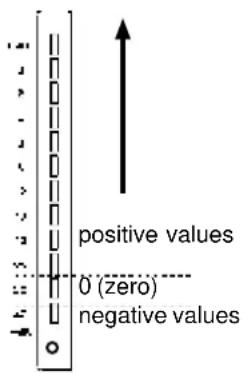
The meters can also be used to give a visual indication of the track delay.
Press SHIFT and one of the REC FUNCTION keys (as described in 4.1.1, “Peak meters”) to toggle this meter mode off and on. The default at power-on is for this mode to be on.
The track delay, expressed in
seconds, is between -4 to +150 milliseconds. At a typical sound propagation rate, the maximum value corresponds to about 50 meters (about 160 feet) of distance.
7.4 Sub-mixer
One important feature of the DA-78HR is the ability to mix input sources and off-tape signals into a stereo signal which is routed to tracks 7 and 8 and can be output at the rear panel SPDIF (COAXIAL) output (as well as through channels 7 and 8 of the TDIF-1 digital and analog outputs). As well as the track delay available on the DA-78HR for the tape tracks, this internal mixer also features level and pan controls, so that a simple mix can be obtained.
This mixed signal is output only when the MIXDOWN indicator is lit. Pressing the (unshifted) MIXDOWN key will toggle the indicator between on and off.
A temporary “patch” can also be set up for this submix, overriding the current input patch settings while the mixdown mode is active.
NOTE
When MIXDOWN is on, the signals from channels 1 through 6 (analog and digital) are not output.
7.4.1 Entering mixdown mode
1 Make sure theSHIFT indicator is off.
2 Press the MIXDOWN key. The MIXDOWN indicator will light.
Pressing the MIXDOWN key again (with shift mode off) will exit mixdown mode.
7.4.2 Setting the master level
This is the master level of all signals output through channels 7 and 8.
1 With mixdown mode enabled, press the SHIFT key so that the indicator is flashing.
2 Press the MIXDOWN (LEVEL/PAN) key. This enters the level/pan setting mode.
3 If the display does not show NST.L 888 (MST L xxx — master level), continue to press the LEVEL/PAN key until this is shown.
Repeated presses of the LEVEL/PAN key or the currently-selected channel (as explained below) will cycle through the following:
master level → channel level → channel pan → channel input selection
4 Use the data knob and/or the ▲ and ▼ keys to change the level between (- dB) and 27(0 dB) .
The 7 and 8 meters may be used to show the level (toggle with SHIFT+REC FUNCTION). The 0 dB segment represents a value of 127, and the -12 dB segment represents a value of 64.
7.4.3 Leaving edit/pan setting mode
When the unit is in edit/pan setting mode as above, it can be returned to normal operations (as shown by a change in the display) by either of the following methods:
Entering another shift mode function (e.g. delay)
or
Pressing the SHIFTkey so that the SHIFT indicator stops flashing (exiting shift mode).
NOTE
Remember that turning off the edit/pan setting mode will not automatically turn off the mixdown mode. To turn off the mixdown mode, you must turn off the shift mode and then press thMIXDOWN key.
7.4.4 Setting levels and pan positions
To set the individual channel levels and pan positions:
1 Make sure that the unit is in level/pan setting mode, as described above (7.4.2, "Setting the master level").
2 Press the REC FUNCTION key whose number corresponds to the channel you want to set. The REC FUNCTION Indicator at the bottom of the meter will start to flash, showing that this is the active channel being edited.
7 - Advanced operations
The display will show the level and pan position of the channel. For example, D2P - c would indicate a level of 102 and a center pan position.
3 Use the ▲ and ▼ keys and/or the knob to change the level of the active channel.
4 To change the level of another channel, press that channel'REC FUNCTION key.
The meters may be used to show the value of the channel levels (the default is for this function to be on, and it may be toggled with the SHIFT+REC FUNCTION combination).
5 Press the LEVEL/PANkey or the REC FUNCTION key of the currently active channel to change the cursor (flashing period) to the pan setting.
$$ \left[ \begin{array}{c} \text {Pan values range from} ^ {P}. L - - \ \text {(PL- hard left) through P.L62} \ \text {(immediately to the right of the} \ \text {hard left setting),} ^ {P}. - c - (\text {P.-C-} \ \text {center) and P.r62 (PR62 -} \ \text {almost hard right) to } ^ {- - r} \ \text {(P.-R-hard right).} \ \text {The meters are also be used to} \ \text {show the pan settings. Press} \ \text {SHIFT and one of theREC} \ \text {FUNCTION keys (as described in} \ \text {o} \end{array} \right] $$
4.1.1, “Peak meters”) to toggle this meter mode off and on. The default at power-on is for this mode to be on.
6 Use the ▲ and ▼ keys and/or the knob to adjust the pan settings of the active channel.
7.4.5 Setting the sub-mixer input sources
1 From the pan setting, as described immediately above, press either the REC FUNCTION key of the active channel, or the LEVEL/PAN key.
2 The display will show the current input source for the channel, e.g. in 1 t1 (In 1 t1—the input source for channel 1 is track 1).
3 Use the ▲ and ▼ keys to cycle through t l through t B (track 1 through 8), R l through R B (analog inputs 1 through 8) and d l through d B (digital inputs 1 through 8).
4 Pressing the ▲ and ▼ keys together will “normalize” the sub-mixer, feeding each channel
with the output of the correspondingly-numbered track.
NOTE
These assignments are temporary, and remain only as long as the mixdown mode is enabled. When the mixdown mode is disabled, the previous input patch-bay settings are restored.
5 To record the mixer outputs onto tracks 7 and 8, arm these tracks and record in the usual way.
7.5 Crossfade times
As mentioned earlier (5.6, “Punch-in and punch-out”), digital punch recording requires that the original and new signal be crossfaded over a short period of time.
The factory default crossfade time for the DA-78HR is 10 ms, and this can be adjusted in 10 millisecond steps to a maximum of 200 ms.
For the most part, 10 ms is an adequate value and will produce seamless punches, but there may be times (matching reverb settings, etc.) when a longer crossfade is required.
1 Press theSHIFT key so that the SHIFTindicator is flashing, and press the MENU key until the display shows Audio.2-- (AUDIO2--).
2 Press theSUB MENUkey until the display shows c. FAdE000 (C FADE xxx), where xxx is the current crossfade time in milliseconds.
3 Use the ▲ and ▼ keys to adjust the crossfade time (10 through 200 ms in 10 ms steps)
7.6 Vari speed (pitch control)
The speed of recording and playback (and hence the pitch) of the DA-78HR can be adjusted to 6% above or below normal speed in 0.1% steps.
NOTE
You cannot operate the pitch control when the DA-78HR is slaved to another unit, or synchronized to an external word clock. If the clock is changed to external while varispeed is on, the VARI SPEED indicator will go out. The indicator will also go out if chasing is enabled while varispeed is on.
7.6.1 To set a non-standard speed
1 Press theVARI SPEEDkey. Its indicator will light, and the SHIFTindicator will flash.
2 Use the ▲ and ▼ keys to change the value (maximum +6.0%, minimum -6.0%, in 0.1% steps).
Reset the value to 0.00% by pressing and holding either of the ▲ or ▼ keys, and pressing the other.
3 Press the SHIFT key to turn off the setting mode. The VARI SPEED indicator will continue to be lit, showing that varispeed is currently enabled.
4 Turn off varispeed (when the/ARISPEED indicator is lit) by pressing the VARI SPEED key to turn the indicator off.
NOTE
The VARI SPEED indicator will light whenever the varispeed is enabled, even if the speed is set to 0.0%.
Playback and recording will now take place at the new speed.
7.7 Shuttle operations
The shuttle key, indicator and knob are used to simulate the “rock and roll” location method on open-reel tape decks, allowing you to locate a point on tape through audible cues.
As the knob is moved from the center detented position, the shuttle speed becomes higher.
The variation in speed is not continuous; but as you turn the knob from the center position, the shuttle speed changes, following these values (relative to normal speed): 0.25, 0.5, 1.0, 2.0, 4.0, 8.0. The 1.0 speed is only available when shuttling in the forward direction.
Shuttle operations are only possible when the SHUT-TLE indicator is lit (press the SHUTTLE switch).
If the SHUTTLE knob remains untouched at the center position for 10 seconds, the shuttle mode is disabled, and the indicator goes off.
7.7.1 Shuttle monitoring
This is also covered in 6.3, “Shuttle monitor”. The default behavior of the DA-78HR is that when shuttling the tape, you monitor off the recorded tape.
NOTE
When monitoring in shuttle mode, the monitor signal is attenuated by 12 dB (to avoid possible damage to ears and speakers).
When AUTO MON is on, the monitoring of any armed tracks will be off-tape, unless the SHTL MON is on, in which case, the monitoring of armed tracks will be source input. The monitoring of all other (unarmed) tracks can still be switched on a track-by-track basis using the tracks' INPUT MONITOR switches.
The SHTL MON key is only enabled when AUTO MON is on. When AUTO MON is off, it has no effect.
7.7.2 Shuttle muting
As explained above, shuttling the tape will usually allow off-tape monitoring. However, there may be times when you will want to mute all off-tape signals when shuttling. This procedure is described in 6.4, "Shuttle muting".
7.8 Meter modes
The DA-78HR peak bargraph meters can be customized to suit your working preferences. Both the peak hold time and the “ballistics” of the meters can be adjusted.
7.8.1 Peak hold time
1 Press theSHIFT key so that the SHIFT indicator is flashing, and press the MENU key until the display shows SYSTEM-- (SYSTEM-).
2 Press the SUB MENU key until the display shows PZ. HLD. 80 (PK HLD xx— peak hold) with the current value for this setting.
3 Use the ▲ and ▼ keys to change the value between 0 and 9 seconds or cnt (CNT—continue—which will permanently display the maximum peak signal level. This can be useful if you are doing a “dry run” rehearsal, but you cannot keep your eyes on the meters all the time that the rehearsal is going on).
To turn off the peak hold display if n has been set, change the peak hold value to seconds and the meter segments will "drop back".
7.8.2 Meter ballistics
Use a similar process to change the “fall-back” ballistics of the peak meters. You cannot change the rise time of the meters, which are fixed with peak meter characteristics.
1 Press theSHIFT key so that the SHIFTindicator is flashing, and press the MENU key until the display shows SYSTEM-- (SYSTEM-).
7 - Advanced operations
2 Press theSUB MENU key until the display shows-L5. (RLS—release) and then changes to the current value for that setting.
3 Use the ▲ and ▼ keys to change the value between the FAST (FAST), SLOB (SLOW) and nEd (MEDIUM) settings.
7.9 Sine oscillator
The DA-78HR incorporates a digital oscillator for lineup and signal tracing purposes. This oscillator is a sine-wave oscillator at either the standard tuning frequency of 440 Hz or a tape line-up signal at 1 kHz.
The oscillator signal level is at the nominal signal level (but note that since the oscillator is a constant sine wave, it cannot truly be compared with “real-world” transient signals).
To operate the oscillator:
1 Press the SHIFTkey so that theSHIFTindicator is flashing, and press the MENU key until the display shows Audio 2-- (AUDIO2--).
2 Press theSUB MENU key until the display showso5c. 888 (OSC xxx, for oscillator, with the current setting).
3 Use the ▲ and ▼ keys to switch the oscillator between the different settings FF (OFF), 440 (440), and I^ (1k).
When the oscillator is turned on, it overrides all other track inputs.
The oscillator setting is not backed up with the other settings.
NOTE
When using the oscillator, you should turn down the monitor levels in the control room and studio to avoid damage to your ears (and the speakers).
7.9.1 Recording the oscillator
As mentioned above, the oscillator overrides all other track inputs, regardless of whether digital or analog input has been selected.
Recording the oscillator test tone is therefore similar to any other recording operation.
7.10REC MUTE (recording silence)
There may be times when you wish to prevent any signal from reaching an armed track (in other words, when you record, you are recording silence onto the track.
1 Press the SHIFT key so that the SHIFT indicator is flashing, and then press the MENU key until the display shows Audio. I-- (AUDIO1--).
2 Press theSUB MENU key until the display briefly shows rEc. nute (REC MUTE) and then changes to show the current setting (the default is all off).
3 Change the settings using the ▲ and ▼ keys.
4 To set record muting for individual tracks, use the track REC FUNCTION keys as track selection keys, and change the settings individually for each track using the ▲ and ▼ keys.
The display will show the track number and the current mute setting (e.g. L_r 1 OFF (TR 1 OFF)).
5 When no track is selected using the REC FUNCTION keys, the display reverts to ALL (ALL), as it does if all tracks are the same value.
If the SHIFT and REC FUNCTION keys are used, each meter shows the record mute status of the correspondingly-numbered track, as shown here (only one segment lights to show the mute status).
Press SHIFT and one of the REC FUNCTION keys (as described in 4.1.1, "Peak meters") to toggle this meter mode off and on. The default at power-on is for this mode to be on.
Pressing the ▲ and ▼ keys together makes the defaultALL OFF setting.
7.11 Dither
Dither is the technique of adding a known noise to low-level signals, especially when converting from a high number of bits (for instance 24 or 20 input bits, as in the case of the DA-78HR) to a lower number
(for instance 16, the DA-78HR's non-HR tape word length) to improve quantization.
Paradoxically, this technique of adding noise removes quantization noise and distortion at low signal levels and improves the overall distortion figures. ^1
Though quantization noise is reduced, there is a loss of a few dB in the signal-to-noise ratio. For this reason, the DA-78HR does not implement dither as a standard, but allows you to choose between no dither, rectangular or triangular (the shapes refer to the distribution of values in the digital noise). Rectangular gives about 3dB better signal-to-noise ratio than triangular, but there is noise modulation, which may be audible when recording and playing back low-level program sources.
NOTE
Dither can be turned on and off while recording is taking place. However, there will probably be an audible change in the sound quality. We suggest making a test recording before a session. In this way you will be able to make an instant assessment of the effects of the different dither settings on your program material.
7.11.1 Selecting dither settings
1 Press theSHIFT key so that theSHIFTindicator is flashing, and then press the MENU key until the display shows Audio. I-- (AUDIO1--).
2 Press theSUB MENUkey until the display shows dith. 888 (DITH xxx where xxx is the current setting).
3 Use the ▲ and ▼ to select the dither function you want (either FF (OFF), r t (RECT) (rectangular) or t r (TRI) (triangular)).
7.12 Advanced output options
7.12.1 Output word length
The output word length from the TDIF-1 (and the SPDIF COAXIAL) outputs can be set to either 16 or 24 bits.
1 Press the SHIFT key so that the unit is in shift mode (SHIFT indicator is flashing).
2 Press the MENU key until the display shows Audio 10.2-- (AUDIO2--).
3 Press the SUB MENU key until the display briefly shows out. bit. (OUT BIT xx), where xx is the current setting.
4 Use the ▲ and ▼ keys to change between 16 and 24 bits.
NOTE
Simply changing the output word length to 24 bits will not automatically provide better sound quality, if the equipment being fed by the DA-78HR is not capable of accepting 24-bit audio.
7.12.2 Output patchbay
In addition to the integral input patchbay, the DA-78HR also features a patchbay which allows tracks to be routed to different output channels.
This routing is carried out in parallel to both the TDIF digital and the analog sets of outputs.
The default setting is normal (NORMAL), i.e. tracks are output to their correspondingly-numbered output channels.
To make an output patch setting:
1 Press the SHIFT key so that the unit is in shift mode (SHIFT indicator is flashing).
2 Press the MENU key until the display shows Audio 10.2-- (AUDIO2--).
3 Press the SUB MENU key until the display briefly shows out. PATCH (OUT PATCH), followed by the current setting.
4 Press any of the REC FUNCTION keys to select an output channel (not a track) which will have a track assigned to it.
5 The display shows the current setting of this output channel, e.g. cH. 1 tr. 3 (Ch1 tr3 means that output channel 1 is fed by tape track 3. Use the ▲ and ▼ keys to change the track number.
7 - Advanced operations
Track 8
Track 7
Track 6
Track 5
Track 4
Track 3
Track 2
Track 1
Pressing the ▲ and ▼ keys simultaneously returns the output patchbay to the normal state.
The meters display the current assignments of tracks to the output channels. In this case, each meter shows the assignment status of the correspondingly-numbered output channel (not track), as shown here.
Press SHIFT and one of the REC FUNCTION keys (as described in
4.1.1, “Peak meters”) to toggle this meter mode off and on. The default at power-on is for this mode to be on.
7.13Emulation
The DA-78HR can be set to emulate other DTRS types when interrogated by an RC-898 remote control unit or other remote control devices (such as the controllers on the TM-D series of TASCAM digital mixers).
1 Press theSHIFTkey so that theSHIFTindicator is flashing, and press the MENU key until the display shows _intn-- (MAINTN--).
2 Press theSUB MENU key until the display briefly shows EU TYPE (DEV TYPE), followed by the current setting.
3 The default is (naturally) dR-78Hr , but you can use the and keys to select any of the following: dR-88 (DA-88 post-V4 with SY-88 fitted giving all timecode functions when working as a slave with ID 2 or greater), dR-38 (DA-88 pre-V4, with track copy) and dR-98 (DA-88 pre-V4).
NOTE
None of these emulations provides full control of all facilities available on the DA-78HR from the remote control unit. If the remote control unit does not support the DA-78HR, select dR-98 as the emulation. If the controller does not support the DA-98, select dR-88 as the emulation.
7.14 Saving settings to tape
This function allows you to store your settings conveniently on the tape that you have used to make your recordings. This means that you can work at home on your project using your own DA-78HR, take the tape to another facility using the DA-78HR, and set up the other machine in exactly the same way as the original at home. Of course, there are many other uses for this facility.
The settings stored on the tape do not affect the recorded audio data.
To save the current settings to tape:
1 Make sure that there is a formatted tape in the recorder before you start to save the settings to tape. The tape must be stopped before you start the save operation.
2 Press theSHIFT key so that the SHIFT indicator is flashing, and press the MENU key until the display shows SYSTEM-- (SYSTEM-).
3 Press theSUB MENUkey until the display shows SAVE. OFF (SAVE OFF).
4 Press the ▲ key to make the DA-78HR ready for saving the settings. The display will show rERdy (READY).
5 Press the ▲ key again to actually start the save operation.
The DA-78HR will automatically search to the position on the tape where the data will be saved, will write the data, and then rewind and check that the data has been correctly written. While the data is being written and checked, the display shows SRAU (SAVING).
6 When the save operation has finished correctly, the display shows donE (DONE). The tape may now be ejected.
If there is no tape inserted (or the tape has not been formatted) when the save operation is readied, the display shows no TAPE (NOTAPE).
If the tape is not stopped when the save operation is readied, the display shows not Stop (NOT STOP).
If an error is encountered while saving is taking place, the display will show SRAJE Err (SAVE ERR).
7.15Restoring settings from tape
This allows you to recall settings stored on tape as described above (7.14, “Saving settings to tape”).
1 To restore settings, the tape containing the settings must be loaded. The tape must be stopped before you start this restore operation.
2 Press theSHIFT key so that theSHIFTindicator is flashing, and press the MENU key until the display shows SYSTEM-- (SYSTEM-).
3 Press theSUB MENUkey until the display shows LoRd. oFF (LOAD OFF).
4 Press the ▲ key to make the DA-78HR ready for loading the settings. The display will show rEAdy (READY).
5 Press the ▲ key again to actually start the restore operation.
The DA-78HR will automatically search to the position on the tape where the data has been saved, and will read the data, loading it into memory. While the data is being read from tape, the display shows rEAd inG (READING).
6 If the settings data on the tape has been read successfully, the display will show rEAd oL (READ OK). The unit will then re-start, as if power had just been turned on.
If there is no tape inserted (or the tape has not been formatted) when the load operation is readied, the display shows no TAPE (NO TAPE).
If the tape is not stopped when the load operation is readied, the display shows not Stop ( NOT STOP).
If no data can be located on the tape, the display will show no data (NO DATA).
If an error is encountered while the reading is taking place, the display will show rERd Err (READ ERR).
This section describes the techniques and methods to be followed when the DA-78HR is linked to other DTRS units (e.g. TASCAM DA-98, DA-38, DA-88 and of course other DA-78HR units).
Up to 16 DTRS units can be linked, for a total of 128 digital tracks.
If you are connecting DTRS units of different types to the DA-78HR, use the DA-78HR or a DA-98 as the master unit and the other units as slave units.
8.1 Synchronization connections
The cable to be used when connecting the DA-78HR to other DTRS units for synchronization purposes should be a PW-88S cable. This is 1 meter (3 ft.) long. If you require a longer cable, please consult your TASCAM dealer.
NOTE
Be sure to use only the optional PW-88S sync cables. The use of any other cables could damage the DA-78HR.
Be sure to connect the termination plug to the last slave's SYNC OUT connector, or else incorrect functions may occur.
Turn on all the DTRS units in your system, regardless of whether you actually use all of them. A unit or units turned off will make synchronization impossible.
To synchronize multiple DTRS units, use a pre-formatted tape in the master unit, and also in the slave units. Since the DTRS system uses ABS time to achieve synchronization, it is impossible to synchronize using tapes without ABS time recorded on them.
To synchronize multiple DTRS units, all the tapes in each unit must be formatted at the same sampling rate, or synchronization is impossible.
The synchronization connections form a “daisy-chain”, with the master unit at the head of the chain, and the last slave at the tail.
Connections are made from the SYNC OUT of one unit to the REMOTE IN/SYNC IN of the next. This connection also carries the word clock between the DTRS units. Slave units will automatically take their clock through this, as shown by the front panel CLOCK indicators, neither of which will be lit.
There are exceptional circumstances when independent clocks may be necessary. See 8.6, “Individual clock mode” for details.
NOTE
Always make and break all connections with the power to all units in the chain turned OFF.
8.2 Machine ID and master/slave settings
Each DTRS unit in the chain must be assigned a machine ID. The unit at the head of the chain (the master) should have ID number 1.
Though not strictly necessary, we suggest that IDs are assigned in a consecutive sequential order from the head of the chain.
8.2.1 Differences between DTRS models
The DA-78HR, DA-98 and DA-38 use machine IDs that are set by software (the machine must be turned on for the ID to be set). The values for the IDs of these models start at “1” and go up to “16”.
The switch on the back of the DA-88 is only operative when the unit is turned off. It is marked from “0” through “F”.
When including DA-88s and DA-78HRs in the same chain, add 1 to the number shown on the DA-88's rear panel machine ID switch to make the DA-88's machine ID match the series of the DA-78HR (and DA-98 and DA-38) IDs. Any DA-88 whose Machine ID is not 1 (the switch has been set to a value other than 0) will show its Slave ID briefly at power-on.
Therefore, for a chain of three units; a DA-78HR as master, with a DA-98 and DA-88 as slaves, the machines' IDs should be set as follows:
| Unit | ID as shown | “Real” ID | How the ID is set | Power on or off when ID is set |
| DA-78HR 11 Tape counter | menu system | ON | ||
| DA-98 2 | 2 | Menu system | ON | |
| DA-88 2 | 3 | Rotary switch on rear panel | OFF | |
It therefore makes sense to set the machine IDs of all DA-88s in the chain first, immediately after connections have been made with the power off, and then turn on power to all units before setting the machine IDs of all DA-78HRs, DA-98s and DA-38s in the chain.
NOTE
When you set the machine IDs, you can set the ID of any machine first, but we recommend doing this in a
8 - Synchronization with other DTRS units
standard sequence, working from the head of the chain to the end.
8.2.2 Setting machine ID
1 Press theSHIFTkey so that theSHIFTindicator is flashing, and press the MENU key, until the counter shows SYSTEM-- (SYSTEM--).
2 Press theSUB MENU key until the display shows id. SEL. 88 (ID SEL xx), where xx is the current machine ID setting.
3 Use the ▲ and ▼ keys to change the value between 1 and 15.
NOTE
If you try to set the machine ID to anything other than 1, when no sync cable is connected, an error message will be shown.
8.2.3 Master/slave settings (CHASE mode)
Each unit with an ID greater than 1 is regarded as a slave unit.
1 For each slave unit in the chain, press the SHIFTkey so that the SHIFT indicator is flashing, and press the MENU key, until the counter shows SYSTEM-- (SYSTEM--).
2 Press theSUB MENU key until the display briefly shows inE.node (TIME MODE) and then changes to show the current time mode (which is either ABS—absolute or TC—time-code).
3 If any slave unit shows TC, use the ▲ and ▼ keys to change this tABS.
4 On each slave unit, press the CHASE key. The CHASE indicator will start flashing.
5 Press any of the transport controls on the master unit (machine ID 1). The slave unit(s) will synchronize and follow the transport commands of the master.
When a slave unit is locked to the master unit, its CHASE indicator will light steadily. While chasing, the transport keys of the slave unit are disabled.
6 To turn off chase mode on a slave unit, press the CHASE key so that the CHASE indicator goes off.
NOTE
When chasing, it may take some time before chase lock is achieved. A slave unit cannot start recording until it has achieved chase lock status.
8.3 Machine offset
It is sometimes necessary to offset a slave unit in the chain relative to the master unit. This offset can be set to sample accuracy to a maximum value of ± two hours.
NOTE
This offset is unrelated to timecode offset and refers only to the machine offset when synchronized to other DTRS units.
8.3.1 Setting machine offset
1 Press the SHIFT key so that the unit enters shift mode (flashing SHIFT indicator).
2 Press the AUTO IN/OUT (OFFSET) key.
3 The display will show RbS. ofST. (ABS OFST) and the current offset (if any has been set).
4 Use the ▲ and ▼ keys to set the offset for the slave unit, and the SHIFTed ▲ and ▼ keys to move the cursor to the different fields. The OFFSET key can also be used as a right cursor key.
See 4.3.5, ““Left” and “right” keys” for details of setting values in a time field.
5 You can also change the sign of the offset value between by moving the cursor to the sign.
When a non-zero offset is set, the front panel OFFSET indicator will light.
NOTE
If you change an offset value (timecode or ABS), any punch points, location memories, etc. will be invalidated. For example, if you change the offset to 00:30:00.00 (30 minutes) from 00:00:00.00 (no offset), a punch point which was previously at 00:33:00.00 (33 minutes into the tape) will still have the same value (00:33:00.00), but will now be only 3 minutes into the tape.
8.3.2 Cancelling machine offset
To cancel machine offset, simply set the offset value to 00:00:00.00.
1 Enter the offset setting, as described above.
2 Press and hold down the ▲ key and press the ▼ key to reset the value.
Machine offset will now be cancelled and the OFFSET indicator will go out.
8.3.3 Setting machine offset "on the fly"
As well as entering an absolute number, it is also possible to enter a number “on the fly” as the tapes are playing.
1 Locate the two tapes (master and slave) so that they have the right offset, either by playing the tapes and pausing them or carry out the next operation while one or both tapes is being played back.
2 On the slave unit to be offset, press and hold the SHIFT key, and press the AUTO IN/OUT (OFFSET) key at the correct offset time to capture and store the offset.
The display will briefly show AT. OFFSET (AT OFFSET), and the current difference between the master and slave tapes will be stored as an offset.
NOTE
The value entered in this way can be edited later using the technique described above.
You cannot determine the offset from an unformatted tape, or if either tape is currently displaying a negative ABS value.
8.3.4 An example of setting offsets
A practical example of setting offsets is given here.
The master DA-78HR contains the tape with the dialog and reference tracks from the video worktape. Another DA-78HR (the slave) has a tape with some tracks containing video backing music. It is necessary to produce an offset between the two so that when the master is played, the music tracks will start at the correct time relative to the dialog and reference tracks.
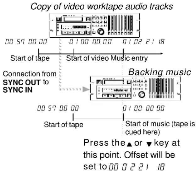
flowchart
graph TD
    A["Copy of video worktape audio tracks"] --> B["Start of tape"]
    B --> C["Start of video Music entry"]
    C --> D["Backing music"]
    D --> E["Start of music (tape is cued here)"]
    E --> F["Start of tape"]
    F --> G["Connection from SYNC OUT to SYNC IN"]
    G --> H["Press the ▲ or ▼ key at this point. Offset will be set to 00 0 2 2 1 18"]
1 Locate the slave tape with the backing music to the start of the music.
The shuttle mode is useful here (see 7.7, “Shuttle operations”).
2 Rewind the master to a little before you want the music to enter.
3 Start playing the master DA-78HR.
4 When the music entry point is reached, press and hold the SHIFT key and press the AU TO IN / OUT key to capture the offset point.
5 Stop the master, and set the slave into CHASE mode (8.2.3, "Master/slave settings (CHASE mode)").
6 Rewind the master to a little before the music entry and start playing.
The slave machine should now follow the transport movements of the master, with the appropriate offset, so that the music enters at the right point.
8.4 Digital dubbing
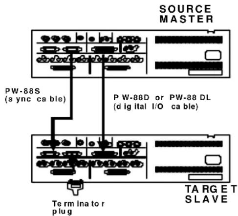
When you copy tapes between DTRS units in the digital domain, there is no loss of quality. A “work-tape” or copy is therefore indistinguishable from the original. Additionally, the DA-78HR uses low-cost media (Hi8 video cassettes), which makes it easy to back up important projects.
NOTE
When you copy tracks from DA-88 units, the word length should be set to 16 bits (5.4.2, "Selecti ng input word length").
You may want to exploit these features of the DTRS system to make archive copies, and “safety copies” of important material (see 1.5, “Recommended tapes” for our suggestions on tape use).
1 With the power to all units turned OFF, make the synchronization connections as described in 8.1, "Synchronization connections".
Remember to terminate the slave unit.
2 Connect the DIGITAL I/O of the master unit (source) to the DIGITAL I/O of the slave (target).
Use only the approved cables (PW-88D or PW-88DL) to connect the DTRS units. Use of any other cables can cause damage to the units and will invalidate the warranties.
3 Turn on both units. Make sure the machines' IDs are correctly set (8.2.2, "Setting machine ID").
4 Insert the master tape into the source master and a blank tape, formatted with the same sampling frequency and with the same recording resolution as the master tape, into the target slave.
5 Select “all digital” as the input source on the target slave (5.3, “Input selection”).
6 Put the target slave machine intoCHASE mode (8.2, "Machine ID and master/slave settings").
7 Locate the master tape to a point before the material you want to duplicate.
The target slave will also locate since it is in chase mode.
8 Arm all tracks (REC FUNCTION) on the target slave machine.
9 Make sure that all REC FUNCTION switches on the source master are turned OFF.
NOTE
If any REC FUNCTION switches on the source master are turned on, you will erase your master tape! You may want to use the tape's write-protect tab (5.2.3, "Write-protecting cassettes").
10 On the master machine, hold down RECORD and press PLAY.
No recording will take place on the source master, but the tracks will be recorded digitally on a one-to-one basis to the target slave.
There is no need to carry out any special pre-dubbing procedure such as timing the digital output – the digital and analog outputs are separate.
You can use the input patchbay on the target slave machine (5.3.2, "Input patchbay routing") to transfer tracks from the source master tape to different tracks on the target slave.
Note that you cannot combine tracks by this method.
8.5 Synchronized formatting
When several units are connected together, you can format several tapes simultaneously, using one machine as the master. This can be a very convenient way of saving time and effort.
1 Make sure that all machines are connected together using the SYNC connections, as described above, and that the last unit in the chain is terminated.
2 Load a blank unformatted tape into each DTRS unit.
Make sure all tapes are the same length.
3 Press theCHASE key on all of the slave DTRS units. The indicator will flash.
4 Press FORMAT/Fs twice within five seconds, on each of the DTRS units (master and all slaves) so all machines are ready to start formatting.
If you press the CLEAR key while the FORMAT indicator is lit steadily, you will cancel the format operation.
5 Select the same sampling rate (48 kHz or 44.1 kHz) on each DTRS unit.
Any slave DTRS unit which has a different sampling frequency selected from that selected on the master will display an error message.
6 Press and hold PLAY and press RECORD on the master. All slave unit CHASE indicators will light steadily, and the tapes will start to be formatted in synchronization.
8.5.1 Recording while formatting
As with a single-machine format (5.1.4, “Recording while formatting”), it is possible to record while formatting on multiple machines.
You may want to use this feature when making a live multi-machine recording, and there has not been time to format all the tapes in advance of the performance.
Remember that you should let the tapes run to the end—you should not halt the formatting/recording process part of the way through the tape.
8.6 Individual clock mode
There are some circumstances where it may be necessary to use independent reference clocks on a chain of DTRS units when TC time mode (see 9.2, “Tape timecode mode”) is selected.
There are two settings, AUTO and INDVID (individual). AUTO is the default, and the unit behaves as follows when this is selected.
| Slave unit's Time Mode | Master DA-78HR | Slave DA-78HR units |
| ABS All clock sources | DTRS sync | |
| TC | Internal | Internal |
| Word sync | DTRS sync |
In individual mode, the unit behaves as follows:
| Slave unit's Time Mode | Master DA-78HR | Slave DA-78HR units |
| ABS | All clock sources | DTRS sync |
| TC | Internal, WORD or DIGITAL IN |
1 Press theSHIFT key so that the SHIFTindicator is flashing, and press the MENU key, until the counter shows SYSTEM-- (SYSTEM--).
2 Press theSUB MENUkey until the display briefly shows cLOP. node (CLOK MODE) and then changes to the current setting.
3 Use the ▲ and ▼ keys to change between the Auto (AUTO) and induced (INDVID) modes.
8.7 Error messages
These error messages refer to DTRS synchronization:
E. d 10 (E DIO)—appears if the digital cable is not connected. Re-connect the correct cable to the DIGITAL I/O connector.
E. cLoc (E CLOC)—appears when the sync cable is not connected, the master has been turned off, or the master's sampling frequency is different from that of the slave unit's. Recheck these parameters.
If either of these messages appears, correct the fault to return to normal operation.
9 - Operations related to timecode
The DA-78HR contains synchronization facilities, including a SMPTE/EBU timecode generator, which allow it to act either as a timecode master or a timecode slave when connected in a timecode chain.
If timecode is recorded on tape, a special discrete subcode track is used, which leaves all eight tracks free for recording and playback of audio material. Note that this subcode is available both as analog SMPTE/EBU timecode and also as MTC.
The DA-78HR is able to synchronize with external timecode devices, even if the DA-78HR tape has not been striped, by converting its internal servo subcode (ABS) to timecode “on-the-fly”.
A full range of options is provided for full compatibility with the widest possible range of other equipment.
9.1 ABS and timecode
In some parts of this manual we will use the phrases “ABS” and “TC”. Here, we explain these two different timing reference methods and the differences between them.
9.1.1 ABS time
“ABS” stands for “Absolute”, and is the absolute time of the tape as recorded on the subcode of the tape. This timing starts at the beginning of the tape with a value of 00:00:00:00. This is the timing reference used when the DA-78HR is not using timecode.
Timecode contains a fixed number of frames per second. However, the ABS method of timing works in a slightly different way.
In three seconds of time, there are 100 frames. These frames are allocated as follows:
| Second | Number of frames | Maximum frame value displayed |
| 00 – 01 33 32 | ||
| 01 – 02 33 32 | ||
| 02 – 03 34 33 |
This pattern is repeated every three seconds, as you will notice when you set frame values using the menu system in ABS mode. When multiple DTRS units are connected together in DTRS sync mode, the master unit always outputs ABS timings to the slave unit(s).
9.1.2 Tape timecode
“TC” stands for timecode, and is shown whenever a timecode value is used rather than the ABS value. The timecode may be internal or external and can be received and transmitted via the MIDI connectors, or timecode synthesized from the ABS subcode (9.2, "Tape timecode mode").
Whether the timecode is generated or synthesized, we will refer to it as “timecode” in this manual, to distinguish it from ABS timing values.
Timecode can be re-produced independently of ABS timings and can be of any frame format supported by common timecode standards.
Timing information received and transmitted from and to external controllers will always be referenced to timecode values.
When the DA-78HR is referenced to its absolute timecode, the ABS indicator to the left of the tape counter will light, and when referenced to timecode (internal or external), the C indicator will light.
9.1.3 Selecting TC or ABS timing
NOTE
This procedure is fundamental to synchronization operations. If you select absolute timing mode when you want to synchronize with timecode, you will be unable to synchronize the DA-78HR.
To change between the two different time reference modes, perform the following procedure:
1 Press the SHIFT key so that the SHIFT indicator is flashing, and then press the MENU key so that the display shows SYSTEM-- (SYSTEM-).
2 Press theSUB MENUkey until the display briefly shows t. inE. node (TIME MODE followed by t. nd. 000 (TMD xxx)—the current setting for this parameter, as described below.
3 Use the ▲ and ▼ keys to select either Ab5 (ABS) or Ec (TC) (the default is Ab5).
The appropriate indicator by the time display will light.
9.2 Tape timecode mode
The following procedure allows you to select the source for tape timecode (including using ABS timings, which are used to synthesize SMPTE/EBU timecode. This synthesized timecode is treated exactly as if a tape had been striped with timecode).
1 Press the SHIFT key so that the SHIFT indicator is flashing, and press the MENU key until the displays shows _C - - (TC-) .
9 - Operations related to timecode
2 Press theSUB MENU key until the display briefly shows RPE. tC (TAPE TC), followed by the current setting.
3 Use the ▲ and ▼ keys to change the value of this parameter between tr (TC TRK) and conv RbS (CONV ABS).
TC TRKmeans that timecode recorded on the tape will be used as the source for the timecode.
CONV ABSmeans that the ABS time (subcode) will be converted to timecode and output as timecode.
9.2.1 TAPE TC setting
You should only use this setting if you have already striped the dedicated timecode track with timecode (either from an external source or from the DA-78HR's own internal generator).
If you have selectedTC TRK from the menu above, any timecode recorded on the tape will be used as the tape timecode source.
9.2.2 ABS setting
If you have selected CONV ABS in the menu above, the ABS subcode time from the tape will be used as the timecode, with the start of the tape having a timecode value of 00:00:00.00, as with the ABS code itself.
The timecode frame rate used will be the frame rate as selected in 9.3, "Selecting the frame mode")
NOTE
If you are using ABS timings as timecode, the hours, minutes and seconds of the ABS time will correspond to the converted timecode unless the frame rate is set to 29.97 non-drop or 30 drop. In these cases, the difference between ABS values and timecode values will be about 2 seconds per hour.
9.3 Selecting the frame mode
The DA-78HR can use the following standards for timecode (including timecode synthesized by the ABS to TC facility):
Frame mode (fps) Display
| 30 non-drop | 30nd (30ND) |
| 30 drop | 30df (30DF) |
| 29.97 non-drop | 29nd (29ND) |
| Frame mode (fps) | Display |
| 29.97 drop (default) | 29DF (29DF) |
| 25 | 25 (25) |
| 24 | 24 (24) |
When using the DA-78HR to chase to a timecode master, the system frame mode on the DA-78HR must match the frame mode of the timecode master, otherwise chase operations are not possible.
The system frame mode is automatically set when a tape which has been striped with timecode is inserted, (or if power is switched on with a striped tape already inserted in the unit). The frame mode recorded on the tape will be used as the system frame mode.
However, the system frame mode may be changed following the procedure below.
The system frame mode will determine the type of timecode output, even if it differs from the tape time-code (the type of which can be viewed as described in 9.5.8, “Checking the frame mode of striped time-code”).
The DA-78HR also outputs timecode synthesized from the ABS code CONV ABS as described in 9.2, "Tape timecode mode") using the frame mode set here.
The DA-78HR's internal timecode generator also uses this frame mode when generating timecode.
To change the system frame rate:
1 Press the SHIFT key so that the SHIFT indicator is flashing, and press the MENU key until the displays shows _C - - (TC-) .
2 Press theSUB MENUkey until the display briefly shows Fn.node (FRM MODE), followed by the current system setting for this parameter (e.g. SYS 29df (SYS 29DF)).
3 Use the ▲ and ▼ keys to select the frame mode for your project.
9.4 Timecode input and output
Remember in this section, “timecode” means SPMTE/EBU timecode when referring to incoming timecode. Outgoing timecode will also refer to SMPTE/EBU timecode, unless MTC output is turned on (see 9.4.4, “MTC output”).
9.4.1 Showing input timecode
There are two primary reasons for the DA-78HR to receive timecode: when the DA-78HR is chasing to timecode, and must receive the master timecode, and when the DA-78HR is to record timecode from another unit (but see 9.5.5, “External timecode sources” below).
To view incoming timecode, follow the procedure below:
1 Press theSHIFT key so that theSHIFTindicator is flashing, then press the MENU key until the display shows ·s(TC-) .
2 Press theSUB MENUkey so that the display shows d, SP. 0000 (DISP xxxx) where xxxx is the current setting.
3 Use the ▲ and ▼ keys to change between TAPE (TAPE)(off-tape setting), E4E(EXT—timecode received at the timecode input) and dIFF (DIFF—the difference between the received timecode and the actual position). Use EXT to view the received timecode.
NOTE
Even when the DA-78HR is in ABS mode, this setting has some effect. If TAPE is selected here, the ABS tape time is shown. If DIFF is selected here, and the DA-78HR is chasing using DTRS sync, the difference between the ABS time of the master unit and the slave unit is shown.
To show the frame mode of the incoming timecode:
1 Press theSHIFT key so that theSHIFTindicator is flashing, then press the MENU key until the display shows ·s(TC-) .
2 Press theSUB MENUkey so that the display briefly shows Frn.nodE (FRM MODE), followed by the system frame mode as described in 9.3, "Selecting the frame mode".
3 Press and hold the SHIFT key and press the ▲ key so that the display shows E4E 0000 (EXT xxxx) where xxxx is the abbreviation for the external timecode frame mode. If no external timecode is being received, the display shows: E4E -- (EXT - ).
9.4.2 Timecode input timing
Because of the nature of analog-to-digital conversion, the timecode input to the DA-78HR must be synchronized either to the audio from the digital or analog outputs.
1 Press theSHIFT key so that the SHIFT indicator is flashing, then press theMENU key until the display shows ·s(TC-) .
2 Press the SUB MENU key so that the display briefly shows in. tc. t nG (INTCTMG) and then changes to the current setting.
3 Use the ▲ and ▼ keys to change between AnRLoG (ANALOG) and d iG iEAL (DIGITAL).
9.4.3 Timecode output
The timecode received at the timecode input jack, or the timecode recorded on tape (or synthesized from ABS), can be output from the timecode output jack.
When the DA-78HR is the timecode master, the timecode it outputs should be off tape.
However, when the DA-78HR is in the middle of a timecode chain, you will probably want to retransmit the incoming timecode (the OUT functions as a THRU). This section explains how to perform these operations.
1 Press theSHIFT key so that the SHIFT indicator is flashing, then press theMENU key until the display shows _C - - (TC-) .
2 Press the SUB MENU key so that the display shows out. tc. Src (OUT TC SRC) briefly, and then changes to the current setting.
3 Use the ▲ and ▼ keys to choose between E APE t (TA PE TC), which includes off-tape and synthesized timecode, r EGEN (REGEN), which is regenerated timecode, and -ESHAPE (RESHAPE) which is filtered and re-transmitted by the DA-78HR.
9.4.4 MTC output
It is possible to select whether or not the DA-78HR outputs MIDI timecode, and under what circumstances. The following functions are available:
- M T C ou t put
- MTC output in fast modes (allows sequencers, etc. to keep track)
- MTC output when stopped
The last two of these are dependent on the first, i.e. if MTC is set to be off, it cannot be output in fast or stop modes. All of these are accessed from the MIDI menu:
1 Press theSHIFT key so that the SHIFT indicator is flashing, then press theMENU key until the display shows ·s (MIDI--).
9 - Operations related to timecode
To set the MTC output on or off:
2 Press theSUB MENU key until the display shows on (MTC ON) or off (MTC OFF).
3 Use the ▲ and ▼ keys to change the setting to the required value (on or off).
To set the MTC output when fast or stopped:
2 Press theSUB MENU key until the display shows eitherFAST, ntc (FAST MTC) or Stop, ntc (STOP MTC), followed by the current setting (on or off).
3 Use the ▲ and ▼ keys to change the setting to the required value (on or off).
NOTE
If MIDI is turned off using the MIDI menu (10.1, "MMC enable and disable"), MTC output is also disabled.
9.4.5 Fast linear timecode (LTC) output
The Fast LTC function controls the way in which timecode is output when fast winding the tape, or if shuttling is carried out at greater than normal play-back speed.
1 Press the SHIFTkey so that theSHIFTindicator is flashing, then press the MENU key until the display shows t - (TC-) .
2 Press theSUB MENU key so that the display showsFAST LLC (FAST LTC) briefly, and then changes to the current setting.
3 Use the ▲ and ▼ keys to make the appropriate setting.
There are three settings:
The SFr (5 FRM) setting means that timecode information is not output continuously. Here, the DA-78HR reads the timecode from the tape as it is spooling, outputs 5 consecutive frames at normal speed starting with the value which has been read from tape, then reads the tape again, outputs another 5 consecutive frames based on the new tape position, and so on.
The L E A P (LEAP) setting means that timecode is output continuously during fast operations, and will not be contiguous (it will leap between frames).
The oFF (OFF) setting means that timecode is not output during fast operations.
9.4.6 Timecode output timing
Because of the nature of the digital-to-analog conversion, the timecode which is output from the DA-78HR must be synchronized to match the audio timing from either the digital or the analog audio outputs, whichever set of outputs is in use at the time.
1 Press theSHIFT key so that the SHIFT indicator is flashing, then press theMENU key until the display shows c - - (TC-).
2 Press theSUB MENUkey so that the display shows out. tc. tñG (OUT TC TMG) briefly, and then changes to the current setting.
3 Use the ▲ and ▼ keys to select between AnALoG (ANALOG) and d, G, tEAL (DIGITAL).
9.5 Recording timecode
9.5.1 Selecting the timecode source
The DA-78HR allows you to select one of three sources for recording timecode: the DA-78HR's internal generator, external timecode, or timecode based on tape.
To select the source for recording timecode:
1 Press theSHIFT key so that the SHIFTindicator is flashing, then press theMENU key until the display shows E_c , rE_c -- (TCG REC--).
2 Press theSUB MENUkey so that the display shows tc. rEc. Src (TC REC SRC) briefly, and then changes to the current setting.
3 Use the ▲ and ▼ keys to select a source for the timecode recording from the following options: E4E (EXT), EcG (TCG—timecode generator) and TAPE. Ec (TAPE TC).
If you select E APE. E c, the source of the tape timecode will be used, as determined in the tape timecode selection menu (9.2, “Tape timecode mode”).
NOTE
Generally speaking, timecode should be recorded from an external source only when audio tracks and timecode must be transferred together from external units. In all other cases, we suggest that you use the internal generator or the tape as sources for recording timecode.
If you are recording timecode only, we suggest that you do not use external sources for recording timecode.
Set the source to TAPE TC as described immediately above, and use ABS (see 9.2.2, "ABS setting") as the tape timecode source. This will ensure an accurate match between the timecode and the ABS timing reference (the fact that the generator must be started manually means that there will not be a tight relation between timecode and the ABS timing).
This will also allow you to synchronize multiple DTRS units accurately to external timecode, even though the slave units are not timecode-based.
9.5.2 Recording timecode using the generator
1 Insert a formatted tape into the DA-78HR.
It is possible to format and stripe a new tape simultaneously, by setting up the formatting procedure as described in 5.1, “Formatting a tape” and then following the instructions below.
2 Select timecode as the timing reference (9.1.3, "Selecting TC or ABS timing").
3 Select a frame rate (9.3, "Selecting the frame mode").
4 Press theSHIFT key so that theSHIFTindicator is flashing, then press the MENU key until the display shows . r - - (TCG REC- ) .
5 Select the source of the timecode as the internal generator (9.5.1, "Selecting the timecode source").
6 Press theSUB MENUkey until the display briefly shows STRT. t inE (STRT TIME), followed by the current start time of the generator.
7 Edit the generator start time as described in 4.3, "Menus and sub-menus".
8 To record the timecode, press theSUB MENU key until the display showsEc. rEc. En 0 (TC REC EN 0, i.e. disabled). Use the ▲ and ▼ keys to change the setting to / (enabled).
The TC indicator will start flashing. This setting will return to ☐ (disabled) when timecode recording has finished.
9 To start the generator, press the SUB MENU key until the display shows tUc. Stop (TCG STOP). Then use the ▲ or ▼ key to start the generator running.
The display will show t.c.g. run (TCG RUN).
10 Press and hold the PLAY and press the RECORD key and the tape will start recording. The TC indicator will start flashing faster while timecode striping is going on.
NOTE
You can also start recording (steps 8 and 10) and then start the timecode generator (step 9).
If the method described above (arming the timecode track, and then starting recording) is used, the tape counter is used to show the output from the timecode source (the generator) when the timecode track is armed, flashing when the tape is stopped, and steady when the tape is running.
9.5.3 Generator modes
When the timecode generator is stopped, using the sub-menu command to restart the generator will either restart from the start time as set in 7, or to continue from the time when it was stopped.
1 Press theSHIFT key so that the SHIFT indicator is flashing, then press theMENU key until the display shows E G , rE - (TCG REC-).
2 Press the SUB MENU key so that the display shows tcU, node (TCG MODE) briefly, and then changes to the current setting.
3 Use the ▲ and ▼ keys to choose between RESET (RESET—resume start from set value) and cont (CONT—continue from currently reached value).
9.5.4 Synthesizing timecode from ABS timing
When you are synthesizing timecode from ABS, the tape counter display behaves differently from the way as described above.
The tape counter will not flash when the timecode track is armed and the tape is stopped, and it will not display all hyphens, since the timecode source is always available.
In this case, you can start recording the timecode at any time (before or after) the tape has started moving.
9 - Operations related to timecode
9.5.5 External timecode sources
The following notes should help you when you must record timecode on the DA-78HR from an external source (analog or digital).
As mentioned earlier, you should only need to record timecode from an external source when the audio and timecode tracks have to be transferred together, keeping a strict relationship between the audio and timecode tracks.
In all other cases, we suggest using either the DA-78HR's internal generator or timecode from tape. If you use these as sources, there will be no jitter problems, and any problems of synchronization with the digital audio clock are eliminated
NOTE
When recording timecode from an external digital source, make sure the digital clock of the DA-78HR and that of the external source are synchronized. A warning message will appear if the timecode source and the DA-78HR are not synchronized, but timecode can still be recorded. However, the resulting timecode recording will probably cause synchronization problems in the future.
When recording timecode from another DTRS unit, synchronize the two units using ABS chase (setting the timecode/audio source unit to be a slave unit). After the two units have been synchronized in this way, timecode and audio can be transferred together.
When recording timecode from a digital source (audio or video), make sure that the DA-78HR and the other unit are locked to a common word (audio recorder) clock reference. After the two machines have been synchronized in this way, timecode and audio can be transferred together.
If your analog recorder cannot chase to external timecode, you must first record the timecode from the analog recorder on an audio track of the DA-78HR and then transfer the timecode to the dedicated timecode track.
Timecode recorded on the audio track in this way is synchronized to the audio clock, and can subsequently be transferred (through patching) to the timecode track.
9.5.6 Recording timecode from external sources
1 Set the time mode t (9.1.3, "Selecting TC or ABS timing").
2 Set the timecode record source to E4E (9.5.1, "Selecting the timecode source").
3 To record the timecode, press the SUB MENU key until the display shows t.c. rEc. En. 0 (TC REC EN 0), meaning that timecode recording is disabled. Use the ▲ and ▼ keys to change the setting to 1 (1—enabled).
4 Start the external source to check the status of the external timecode.
If no external timecode has been received since the DA-78HR has been switched on, the tape counter will show all hyphens.
If external timecode has been received since the DA-78HR has been switched on, but is not currently being received, the tape counter will flash.
If the external timecode is currently being received at normal (play) speed, the tape counter will show the value of the timecode currently being received. If the external timecode is being received from a source in fast wind mode, the tape counter will flash.
If the timecode source is not clock-synchronized with the DA-78HR, a warning will be shown on the display screen. In this case, although you can record timecode, it is not recommended, as this will probably cause problems later on.
5 Stop the external timecode source, and rewind or reset it to a point prior to where you want recording to begin.
The tape counter will now start to flash.
6 Restart the source.
The tape counter will display received time-code.
7 Press and hold downPLAY and press RECORD. Timecode will now be recorded from the external source onto the timecode track.
If the tape counter was flashing when the time-code track was armed, the tape counter will now show all hyphens, and nothing will be recorded.
9.5.7 Checking external timecode
You can check received timecode by using the timecode display function as described in 9.4.1, "Showing input timecode".
9.5.8 Checking the frame mode of striped timecode
To view the frame mode of a tape which has been striped with timecode, follow the steps below:
1 Press theSHIFT key so that theSHIFTindicator is flashing, then press the MENU key until the display shows _C -- (TC-).
2 Press theSUB MENUkey so that the display briefly shows Frn node (FRM MODE), followed by the system frame mode as described in 9.3, "Selecting the frame mode".
3 Press and hold the SHIFT key and press the ▲ key twice so that the display shows TAPE (TAPE xxxx) where xxxx is the abbreviation for the frame mode of the timecode striped on the tape. If no timecode has been striped on the tape, the display shows: TAPE -- (TAPE -).
9.6 Chasing to timecode
The following sections describe the operation of the DA-78HR when chasing to external timecode.
The operation of the CHASE key is similar to the way the CHASE key is used when synchronizing DTRS units, but in this case, the machine ID is not used.
9.6.1 Machine ID and timecode
Since a DA-78HR with machine ID set to 1 is always a master unit as regards DTRS sync operation, there is no need to make any setting on such a machine if it is to be a timecode slave. As long as timecode is received at the TIME CODEN connector, a unit whose machine ID is set to 1 will automatically enter timecode chase mode when the CHASE key is pressed.
However, when a DA-78HR unit has its machine ID set to a value other than 1, there is a conflict when the CHASE key is pressed. You must determine whether the chase mode refers to timecode or to the DTRS sync, and this is done using the Time Mode menu (9.1.3, "Selecting TC or ABS timing"). If Rb5 is selected, when CHASE is pressed, the machine will enter DTRS sync mode, but if bc is selected, the machine will attempt to lock to external timecode.
When the DA-78HR is in “chase-ready” mode (the CHASE indicator is flashing) and timecode is received at the TIME CODE INonnector, the DA-78HR will start to chase the timecode. When it is
locked to the incoming timecode, the CHASE indicator will light steadily.
NOTE
The timecode frame rate used on the DA-78HR must match the frame rate of incoming timecode (9.3, "Selecting the frame mode"). If they do not match, the DA-78HR will not chase to timecode. Check the frame rate of the incoming timecode at the source and of the timecode recorded on the DA-78HR's tape.
The timecode used internally by the DA-78HR does not have to be an actual timecode striped tape. Instead, timecode can by "synthesized" from the ABS subcode timings, as described in 9.2, "Tape timecode mode".
The exact ways in which it chases the timecode and handles transport functions, etc. are determined by a number of settings, as described below:
9.6.2 Timecode offset
When a DA-78HR is a timecode slave, you may enter an offset for the audio from the DA-78HR to match the audio (or video sequence) from the timecode master.
As with the machine offset (8.3, “Machine offset”), you can either set this manually, entering the numbers, or set it “on-the-fly” by ear. In either case, once the offset has been entered, it can then be edited.
The offset can be set to subframe or sample accuracy (4.3.6, “Sub-frame values”).
The way in which the timecode offset is set is exactly the same as for a machine (ABS) offset, except that the DA-78HR must first be set up as a timecode slave, as described above (9.6.1, “Machine ID and timecode”).
NOTE
If you change an offset value (timecode or ABS), any punch points, location memories, etc. will be invalidated. For example, if you change the offset to 00:30:00.00 (30 minutes) from 00:00:00.00 (no offset), a punch point which was previously at 00:33:00.00 (33 minutes into the tape) will still have the same value (00:33:00.00), but will now be only 3 minutes into the tape.
9.6.3 Setting timecode offset
1 Press theSHIFT key so that the SHIFTindicator is flashing (shift mode).
2 Press the AUTO IN/OUT (OFFSET) key.
3 The display will show tc. ofSt (TC OFST) followed by the current offset (if any has been set).
9 - Operations related to timecode
4 Use the ▲ and ▼ keys to set the offset for the slave DA-78HR, and the SHIFT ed ▲ and ▼ keys to move the cursor to the e different fields.
You can also use the OFFSET key as a right cursor key.
The front panOFFSET indicator will light when an offset value has been set.
See 4.3.5, “‘Left’ and “right” keys” for details of setting values in a time field. You can set the offset to sub-frame (percentage or sample) accuracy.
5 You can also change the sign of the offset value to a minus value by moving the cursor to the appropriate position and using the ▲ and ▼ keys.
9.6.4 Cancelling timecode offset
To cancel the offset, simply set the offset value to 00 00 00 00.
1 Enter the offset setting, as described above.
2 Press and hold down the ▲ key and press the ▼ key to reset the value.
Timecode offset will now be cancelled and the front panelOFFSET indicator will go out.
9.6.5 Setting timecode offset "on the fly"
As well as entering an absolute number, it is also possible to enter a number “on the fly” as the tapes are playing.
1 Locate the two devices (master and slave DA-78HR) so that they have the right offset, either by playing the tapes and pausing them or carry out the next operation while one or both tapes is being played back.
2 On the slave DA-78HR, press and hold the SHIFTkey, and press the AUTO IN/OUT (OFFSET) key at the correct offset time to capture and store the offset.
The display will briefly show Rt. OFFSET (AT OFFSET), and the current difference between the master unit and slave DA-78HR will be stored as an offset.
9.6.6 Park position
When the DA-78HR is slaved to an external time-code source, it will take some time between the master unit starting to play and starting to transmit timecode for the DA-78HR to read.
These functions allow you to measure and test the optimum pre-roll position for the DA-78HR (when it is a timecode slave) to park itself relative to the master timecode device so that it will lock up and start playing quickly.
1 Press theSHIFT key so that the SHIFTindicator is flashing, then press theMENU key until the display shows t.c. cHS-- (TC CHS--).
2 Press theSUB MENUkey so that the display shows PRrL. PoS (PARK POS) briefly, and then changes toPrL (PRK) followed by the current setting, shown in seconds and frames.
3 Use the ▲ and ▼ keys to adjust the value (maximum is 1 second and 29 frames)
9.6.7 Automatic park position setting
When the DA-78HR is acting as a timecode slave, it can automatically determine the optimum park pre-roll position to sync with the master.
1 Turn the DA-78HR'sCHASE on, if it is off and make sure that the time mode is set to TC.
2 Press theSHIFT key so that the SHIFTindicator is flashing, then press theMENU key until the display shows t.c. cHS-- (TC CHS--).
3 Press theSUB MENUkey so that the display shows PL. POS. TST (PK POS TST) briefly, and then changes to OFF OFF).
4 Play and stop the master tape.
5 Use the ▲ or ▼ key to turn the park test on. The DA-78HR will then rewind so that the relative difference is zero. When the DA-78HR has stopped, go on to the next step below.
6 Play the timecode master.
When the value shown on the display has stopped changing and is stabilized, go on to the next step below.
7 Use the ▲ or ▼ key to turn the park test off. The display shows donE (DONE), and the optimum park pre-roll time for the timecode master is now stored.
9.6.8 Absolute and relative difference
The offset as set above (“Timecode offset” on page 58) can be called the “absolute difference” between the two times. However, if the slave machine “wanders” (actually, this is unlikely), the offset (theoretical difference) will not be equal to the
absolute difference. The “relative difference” is expressed as below:
Relative difference = Absolute difference - Offset
Thus, if the offset is set on a slave machine to +00:10:00.00 (10 minutes) and while chasing, the two machines' counters read as follows:
Master 10 15 12 12
Slave 10 05 12 08
the slave is now 10 minutes and 4 frames behind the master.
Since the slave is meant to be exactly 10 minutes behind the master, the difference, +4 frames, is the “relative difference” between the master and the slave.
To view the and relative differences between master and slave machines:
1 Press theSHIFT key so that theSHIFTindicator is flashing, then press the MENU key until the display shows ·s(TC-) .
2 Press theSUB MENUkey so that the display shows d, SP (DISP) followed by the current setting.
3 Use the ▲ and ▼ keys to make thed,FF (DIFF) setting—the difference between the received timecode and the actual position.
9.6.9 Rechasing timecode
When timecode is received, the DA-78HR can either constantly monitor the internal off-tape timecode (or the ABS equivalent as set in 9.2, “Tape timecode mode”) and the external timecode, issuing “speed-up” and “slow-down” messages to the transport to keep itself in sync (rechasing), or it can synchronize once and run freely, ignoring the incoming timecode.
1 Press theSHIFT key so that theSHIFTindicator is flashing, then press the MENU key until the display shows t.c. cHS-- (TC CHS--).
2 Press theSUB MENUkey so that the display briefly shows rECHS. nd (RECHS MD) and then changes to the current setting.
3 Use the ▲ and ▼ keys to choose between rEchASE (RECHASE) and FrEE (FREE).
While the DA-78HR is re-syncing (speeding up and slowing down), playback output will be muted, unless the clock is set to INT. Usually you should find that the DA-78HR does not need to rechase, however, and you can leave it in free-running mode. If the timecode master tape includes a break in the timecode, though, you may want the DA-78HR to rechase the master.
As well as selecting rechase, you can also select the length of the “rechase window”. This means that if the difference between internal and incoming time-code is greater than the value of this window (1 or 2 seconds in the case of the DA-78HR), the synchronizer will start to rechase.
1 Press theSHIFT key so that the SHIFTindicator is flashing, then press theMENU key until the display shows t.c. cHS-- (TC CHS--).
2 Press the SUB MENU key so that the display briefly shows rEchS. Bd. (RECHS WD) and then changes to the current setting.
3 Use the ▲ and ▼ keys to change between 1 and 2 seconds.
9.6.10 Bypassing timecode errors
As timecode is received from a remote master unit, it may be subject to errors (dropouts on the timecode master tape, etc.). These errors can cause synchronization failure (the DA-78HR will no longer be locked to the timecode of the master unit).
You can set the DA-78HR to bypass and ignore incoming timecode errors of up to 30 frames in length, or up to 10 frames in length.
1 Press theSHIFT key so that the SHIFT indicator is flashing, then press theMENU key until the display shows c. cHS-- (TC CHS--).
2 Press the SUB MENU key so that the display briefly shows Err. BYPAS. (ERR BYPAS) and then changes to the current setting.
3 Use the ▲ and ▼ keys to change between 10 Frn (10 FRM) and 30 Frn (30 FRM).
9.6.11 Individual recording while chasing timecode
If slave DTRS units are chasing a master DTRS unit, the default action is for the slaves' record status to follow that of the master. If the slaves are connected with TC as well as SYNC, and have TC rather than ABS selected as the timing reference, this default behavior can be overridden using the function described here.
1 Press theSHIFT key so that the SHIFT indicator is flashing, then press theMENU key until the display shows tc. cHS-- (TC CHS--).
9 - Operations related to timecode
2 Press theSUB MENU key so that the display shows indu. rEc (INDV REC x) where x is ☐ (disabled) or 1 (enabled).
3 Use the ▲ and ▼ keys to choose between☐ (disabled) and / (enabled).
When this function is enabled, individual recording is possible when chasing to timecode, and when it is disabled, all slave units follow the master's lead.
10.1 MMC enable and disable
The DA-78HR can be controlled using MIDI Machine Control Commands (MMC). To enable and disable the DA-78HR's response to these commands:
1 Press theSHIFTkey so that theSHIFTindicator is flashing, and then press the MENU key until the display shows ·s (MIDI-).
2 Press theSUB MENU key until the display shows n̄ id, on or n̄ id, off (MIDI ON or MIDI OFF.
3 Use the ▲ and ▼ keys to make the appropriate setting.
NOTE
Turning this parameter on and off will also enable and disable respectively the transmission of MIDI timecode (MTC).
10.1.1 Assigning a MIDI ID to the DA-78HR
A MIDI ID is used in a MIDI Machine Control setup to identify each unit in the MIDI chain.
One (and only one) of up to 127 units can be designated as the MIDI Timecode Master for the whole chain.
This MIDI ID is not the same as a MIDI Channel number (even though some units' manuals may refer to it as a "channel number"), and is not connected with the Machine ID (8.2.2, "Setting machine ID"). To set the MIDI ID:
1 Press theSHIFTkey so that theSHIFTindicator is flashing, and then press the MENU key until the display shows ·s (MIDI-).
2 Press theSUB MENU key until the display shows ^1 (D), followed by the current ID number.
3 Use the ▲ and ▼ keys to change the ID to a value between 1 and 127, making sure that this is unique in your setup.
You can also select the default value of LL (ALL), which allows the DA-78HR to accept all MMC commands transmitted over the MIDI network.
Set the MIDI ID using the method described immediately above.
The MMC commands used by the DA-78HR are listed in this section (10.2, "MMC Bit Map Array").
10.1.2 MMC commands and the DA-78HR
An example of a MIDI sequencer being used to control a DA-78HR (using the auto-punch of the sequencer to punch in and out on the DA-78HR tracks) is given below. Note that the sequencing software must be able to transmit MMC commands and also to sync to MTC for this to be effective:
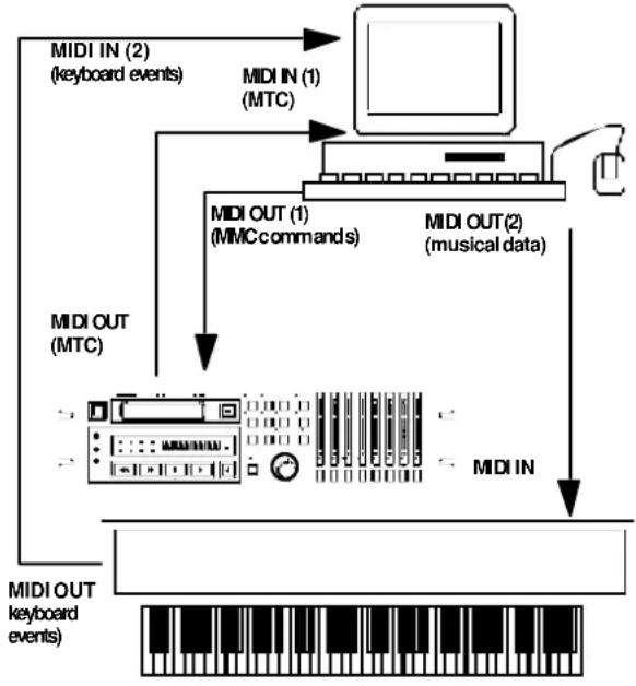
flowchart
graph TD
    A["MIDI IN (2) (keyboard events)"] --> B["MIDI IN (1) (MTC)"]
    B --> C["MIDI OUT (1) (MMC commands)"]
    C --> D["MIDI OUT (2) (musical data)"]
    D --> E["MIDI IN"]
    E --> F["MIDI OUT (keyboard events)"]
    F --> G["Computer"]
    style A fill:#f9f,stroke:#333
    style B fill:#ccf,stroke:#333
    style C fill:#cfc,stroke:#333
    style D fill:#fcc,stroke:#333
    style E fill:#ffc,stroke:#333
    style F fill:#cfc,stroke:#333
The sequencer is set up to transmit MMC commands, and is set so that it synchronizes to SMPTE/MTC.
When a “transport” command is given from the sequencer, the appropriate MMC command is transmitted to the DA-78HR. When the DA-78HR has located and starts playback (or recording), the MTC is transmitted back to the sequencer, which locks in and starts at the correct point.
In this way, though the DA-78HR is the timecode master, the sequencer is the transport master.
The arrangement shown here uses 2 inputs to the sequencer. The same effect could be achieved with the intelligent use of filtering mechanisms.
10.2MMC Bit Map Array
Commands unavailable on the DA-78HR are struck through, as for example (RECORD PAUSE).
| Byte Bit 7 Bit 6 (40H) Bit 5 (20H) Bit 4 (10H) Bit 3 (08H) Bit 2 (04H) Bit 1 (02H) Bit 0 (01H) | ||||||||
| c0 | -0 | (06)RECORDSTROBE | (05)REWIND | (04)FASTFORWARD | (03)DEFERREDPLAY | (02)PLAY | (01)STOP | (00)reserved |
| c1 | -0 | (0D)MMCRESET | (0C)COMMANDERRORRESET | (0B)CHASE | (0A)EJECT | (09)PAUSE | (08)RECORDPAUSE | (07)RECORD EXIT |
| c2 | -0 | (14) | (13) | (12) | (11) | (10) | (0F) | (0E) |
| c3 | -0 | (1B) | (1A) | (19) | (18) | (17) | (16) | (15) |
| c4 | -0 | -0 | -0 | -0 | (1F) | (1E) | (1D) | (1C) |
| c5 | -0 | (26) | (25) | (24) | (23) | (22) | (21) | (20) |
| c6 | -0 | (2D) | (2C) | (2B) | (2A) | (29) | (28) | (27) |
| c7 | -0 | (34) | (33) | (32) | (31) | (30) | (2F) | (2E) |
| c8 | -0 | (3B) | (3A) | (39) | (38) | (37) | (36) | (35) |
| c9 | -0 | -0 | -0 | -0 | (3F) | (3E) | (3D) | (3C) |
| c10 | -0 | (46)SEARCH | (45)VARIABLEPLAY | (44)LOCATE | (43)UPDATE | (42)READ | (41)MASKEDWRITE | (40)WRITE |
| c11 | -0 | (4D)ADD | (4C)MOVE | (4B)MTCCOMMAND | (4A)GENERATORCOMMAND | (49)ASSIGNSYS.MAS | (48)STEP | (47)SHUTTLE |
| c12 | -0 | (54)DEFERREDVARI.PLAY | (53)COMMANDSEGMENT | (52)GROUP | (51)EVENT | (50)PROCEDURE | (4F)DROP.FR.ADJUST | (4E)SUBTRACT |
| c13 | -0 | (5B) | (5A) | (59) | (58) | (57) | (56) | (55)REC STROBEVARIABLE |
| c14 | -0 | -0 | -0 | -0 | (5F) | (5E) | (5D) | (5C) |
| c15 | -0 | (66) | (65) | (64) | (63) | (62) | (61) | (60) |
| c16 | -0 | (6D) | (6C) | (6B) | (6A) | (69) | (68) | (67) |
| c17 | -0 | (74) | (73) | (72) | (71) | (70) | (6F) | (6E) |
| c18 | -0 | (7B) | (7A) | (79) | (78) | (77) | (76) | (75) |
| c19 | -0 | -0 | -0 | -0 | (7F)RESUME | (7E) | (7D) | (7C)WAIT |
| Byte | Bit 7 | Bit6 (40H) | Bit5 (20H) | Bit4 (10H) | Bit3 (08H) | Bit2 (04H) | Bit1 (02H) | Bit0 (01H) |
| r0 | -0 | (06)GENERATORTIME CODE | (05)LOCKDEVIATION | (04)ACTUALOFFSET | (03)REQUESTEDOFFSET | (02)SELECTEDMASTERCODE | (01)SELECTEDTIME CODE | (00)reserved |
| r1 | -0 | (0D)GP5 | (0C)GP4 | (0B)GP3 | (0A)GP2 | (09)GP1 | (08)GP0/LOCATEPOINT | (07)MTC-INPUT |
| r2 | -0 | (14) (13) (12) (11) (10) (0F) | GP7 | (0E)GP6 | ||||
| r3 | -0 | (1B) (1A) (19) (18) (17) (16) (15) | ||||||
| r4 | -0 | -0 | -0 | -0 | (1F) (1E) (1D) (1C) | |||
| r5 | -0 | (26)ShortGENERATORTIME CODE | (25)ShortLOCKDEVIATION | (24)ShortACTUALOFFSET | (23)ShortREQUIREDOFFSET | (22)ShortSELECTEDMASTERCODE | (21)ShortSELECTEDTIME CODE | (20)reserved |
| r6 | -0 | (2D)Short GP5 | (2C)Short GP4 | (2B)Short GP3 | (2A)Short GP2 | (29)Short GP1 | (28)Short GP0LOCATEPOINT | (27)ShortMTG-INPUT |
| r7 | -0 | (34) (33) (32) (31) (30) (2F) | Short GP7 | (2E)Short GP6 | ||||
| r8 | -0 | (3B) (3A) (39) (38) (37) (36) (35) | ||||||
| r9 | -0 | -0 | -0 | -0 | (3F) (3E) (3D) (3C) | |||
| r10 | -0 | (46)SELECTDTIME-CODESOURCE | (45)TIMESTANDARD | (44)COMMANDERRORLEVEL | (43)COMMANDERROR | (42)RESPONSEERROR | (41)UPDATE RATE | (40)SIGNATURE |
| r11 | -0 | (4D)RECORDSTATUS | (4C)RECORDMODE | (4B)FASTMODE | (4A)STOPMODE | (49)VELOCITYTALLY | (48)MOTIONCONTROLTALLY | (49)SELECTEDTIME CODEUSER BITS |
| r12 | -0 | (54)STEPLENGTH | (53)TRACK INPUTMONITOR | (52)TRACK SYNCMONITOR | (51)RECORDMONITOR | (50)GLOBALMONITOR | (4F)TRACKRECORDREADY | (4E)TRACKRECORDSTATUS |
| r13 | -0 | (5B)GENERATORCOMMANDTALLY | (5A)CHASEMODE | (59)RESOLVEDPLAYMODE | (58)CONTROLDISABLE | (57)LIFTERDEFEAT | (56)FIXEDSPEED | (55)PLAYSPEEDREFERENCE |
| r14 | -0 | -0 | -0 | -0 | (5F)MTCSETUP | (5E)MTCCOMMANDTALLY | (5D)GENERATORUSER BITS | (5C)GENERATORSETUP |
| r15 | -0 | (66) (65) | FAILURE | (64)RESPONSESEGMENT | (63)VITC INSERTENABLE | (62)TRACKMUTE | (61)EVENTRESPONSE | (60)PROCEDURE RESPONSE |
| r16 | -0 | (6D) | (6C) (6B) | (6A) | (69) (68) (67) | |||
| r17 | -0 | (74) (73) (72) (71) (70) (6F) (6E) | ||||||
| r18 | -0 | (7B) (7A) (79) (78) (77) (76) (75) | ||||||
| r19 | -0 | -0 | -0 | -0 | (7F)RESUME | (7E) | (7D) | (7C)WAIT |
10.3MIDI Control Change
It is also possible to send use MIDI Control Change messages to control the sub-mixer parameters, as described here:
| Parameter MIDI Control Hex value | ||
| Channel fader Volume (7) 0x07 | ||
| Channel pan | Pan (10) | 0x0a |
| Master fader | Control (9) 0x09 | |
| Channel mute ^a | Control (11) | 0x0b |
a. Values of 0 through 63 turn mute on, values of 64 through 128 turn it on.
MIDI channels 1 through 8 control channels 1 through 8 on the master DA-78HR in a DTRS chain. MIDI channels 9 through 16 can be used to control channels 1 through 8 on the first slave DA-78HR in a chain.
10.4MIDI System Exclusive
The following are the System Exclusive formats used by the DA-78HR:
10.4.1 Identity Reply
Reply to an Identity Request:
| F0 | SysEx header |
| 7E | Universal SysEx non-realtime header |
| Obtained by subtracting 1 from the Machine ID | |
| <06> | sub-ID #1 — general information |
| <02> | sub-ID #2 — device identity reply |
| 4E | TEACID |
| 01 | Category = recorder |
| 04 | type = digital cassette |
| 04 | interface = direct |
| 0C | machine = DA-78HR |
| Software version of unit . Numbers above decimal point, expressed in binary | |
| Software version of unit . Numbers below decimal point expressed in binary | |
| 00 | Currently unassigned |
| 00 | Currently unassigned |
| F7 | End of SysEx |
10.4.2 TASCAM Exclusive messages
These TASCAM Exclusive messages are developed for controlling DTRS recorders connected to each other via the SYNC IN connections.
The messages follow the following format:
| F0 | SysEx header |
| 4E | TEAC ID |
| Obtained by subtracting 1 from the Machine ID | |
| 11 | Operation code (DTRS SYNC IN) |
| Machine ID set on each DTRS recorder | |
| Command code | |
| Data — format varies according to command | |
| checksum — lower 7 bits of the sum of all numbers from (and including)up to | |
| F7 | End of SysEx |
10.4.3 Track delay
Track delay can be set from -200 through +7200
$$ < c c > = 0 4 $$
$$ < d a t a > \text { is 5 bytes: } < t k > < \mathrm{da} > < \mathrm{db} > < \mathrm{dc} > < \mathrm{dd} > $$
10.4.4 Crossfade
Can be set from 0 to 90 ms in this way
$$ < c c > = 0 5 $$
1 data byte, taking a value from 0 through 9 (0 through 90 ms)
10.4.5 Machine offset
Used to set the machine offset of a slave machine chasing to a master via aSYNC IN connection (the master's chase cannot be set, of course).
The limits of this parameter are ±02:00:00.00 . If a value over or below these limits are entered, the limit value will be set.
$$ < c c > = 0 6 $$
$$ \langle d a t a \rangle \text { is four bytes: } \langle h h \rangle \langle m m \rangle \langle s s \rangle \langle f f \rangle $$
10.4.6 Track Copy Setup
$$ < c c > = 0 9 $$
There are two data bytes:
10.4.7 Track Copy Enable
$$ < \mathrm{cc} > = 0 \mathrm{a} $$
1 byte of data to enable or disable the function. 0 = disable, 1 = enable.
10.5MIDI Implementation Chart
11.1 Head and transport cleaning
The DA-78HR incorporates an internal cleaning mechanism that not only cleans the rotary head, but also the tape as it enters the tape path. The provision of this cleaning mechanism significantly reduces the need for manual cleaning. If, despite the internal cleaning mechanism, the PB CONDITION indicator ⑥ lights, the heads are dirty and manual cleaning procedures should be followed.
NOTE
Use a TEAC HC-8 cleaning tape (recommended) or a dry cleaning tape specially designed for Hi8 8mm video equipment.
NEVER use a wet-type cleaning tape, as this will result in winding problems.
The use of the dry tape will reduce the head life of the DA-78HR by about five hours. Use of manual cleaning is therefore discouraged.
We recommend the following schedule (based on our experience with the DTRS system) for cleaning and maintenance schedules. See 11.1.3, “Checking drum time” below for details of how to check head usage time.
Every 350 to 400 hours
Perform manual cleaning of heads and guides as described below. Check the tape path alignment after cleaning. This requires proper test and measurement equipment, and should be performed only by qualified service personnel.
Every 1000 hours (every third cleaning)
A complete alignment check should be performed.
The above cleaning cycle timings are based on the assumption that the DA-78HR is being operated in a clean environment. A dusty or smoky atmosphere will shorten the time between cleaning operations
NOTE
Most name brand tapes are of very high quality. However, it is sometimes possible to receive “bad” stock which exhibits excessive shedding characteristics. If you receive such tape stock, stop using it immediately, and follow the cleaning procedure as described below.
11.1.1 To clean the heads and transport
1 Press theSHIFTkey so that theSHIFTindicator is flashing, and press the MENU key until the
display shows _intn (MAINTN—maintenance).
2 Press the SUB MENUkey until the display briefly shows cLEN. 0000 (CLEN xxxx), followed by cLEN. off (CLEN OFF).
Here, thexxxx represents the number of times cleaning has been performed.
3 Use the ▲ key to change □FF to □n (ON).
If a tape has already been loaded, it will automatically be ejected.
Pressing ▼ at this point will show the previous display.
4 Insert the cleaning tape.
5 The cleaning tape will "play" for about 5 seconds (the display will show CLEANING (CLEANING)) and then be ejected automatically. The cleaning counter (number of times the heads have been cleaned) will be incremented by one.
- Do not attempt to rewind or fast forward the cleaning tape, either in the DA-78HR or in a video unit. Simply insert it into the DA-78HR when you use it the next time.
- Excessive cleaning can cause excessive wear on the heads. Do not clean the heads too frequently, and never perform the head cleaning procedure more than 5 times running.
- In addition to cleaning the heads, we recommend that you have the DA-78HR checked by an authorized TASCAM service technician every 500 hours or so of use.
11.1.2 Checking error rates
If you hear noise and distortion on playback, even after cleaning the heads, or if you are presented with a tape of dubious quality, you may want to check the block error rate of the tape.
1 Press the SHIFT key so that the SHIFT indicator is flashing, and press the MENU key until the display shows _intn (MAINTN—maintenance).
2 Press the SUB MENUkey until the display shows b. E. r. oFF (BER OFF).
3 Use the ▲ and ▼ keys to change off to on. The PB CONDITION indicator will start to flash.
4 Play the suspect tape. The track meters are used to show the error rate at different location, as listed below:
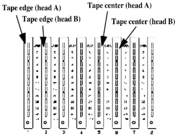
| ... | || | 96-128 |
| = | || | 88-95 |
| , | || | 80-87 |
| , | || | 72-79 |
| , | || | 64-71 |
| , | || | 56-63 |
| , | || | 48-55 |
| , | || | 40-47 |
| , | || | 32-39 |
| , | || | 24-31 |
| , | || | 16-23 |
| , | || | 6-15 |
| , | || | 0-7 (none lit) |
The number of segments lit indicates the blocks containing errors (per group of 128 blocks), as shown here.
It is inevitable that there will be a few errors, but if the meter segments are consistently lit while the tape is playing, something is wrong (and you will almost certainly be able to hear it!).
Use this display to show where the tape is in error, and which head is causing errors. In this way, you can pinpoint any trouble.
If playing another tape seems to remove the errors, the problem is with the tape, otherwise you may want to clean the heads (11.1, “Head and transport cleaning”). Remember not to clean the heads more than 5 times in a row.
NOTE
If, after trying different tapes and cleaning the heads, you still see many errors, you should contact a TASCAM service technician to check your DA-78HR.
5 Use the ▲ and ▼ keys to turn off the error display and use the meters for their normal functions.
11.1.3 Checking drum time
This function allows you to check the number of hours that the drum has been used overall, as well as in fast forward or rewind (search) mode.
1 Press theSHIFTkey so that theSHIFTindicator is flashing, and press the MENU key until the
display shows _intn (MAINTN—maintenance).
2 Press the SUB MENUkey until the display briefly shows drun. t in (DRUM TIM—drum time). The display then changes.
3 Use the ▲ and ▼ keys to choose between d. 0000 (D xxxx — total drum time) and d. S. 0000 (D.S.xxxx—drum search time).
xxxx represents the time in hours shown beside the appropriate parameter.
11.2 Backup memory initialization
The DA-78HR includes non-volatile memory (NVRAM) which preserves almost all user settings after the power is turned off.
To reset these settings to their default values (defaults are listed in 4, "Menu interface, etc.") :
1 Press the SHIFT key so that the SHIFT indicator is flashing, and press the MENU key until the display shows _intn (MAINTN—maintenance).
2 Press the SUB MENUkey until the display shows in it. (INIT).
3 Press either ▲ or ▼ to change the display to show rEADY (READY).
4 Press either ▲ or ▼ once again to initialize all the stored parameters to the factory settings.
The unit will show donE (DONE) and will restart (as if power had just been turned on).
11.3 Checking version numbers
In case of problems, you may need to quote the version number of the DA-78HR's internal software components to a TASCAM representative.
There are three major components of the DA-78HR's internal software: system, front panel and servo. Each of these can be checked independently.
1 Press the SHIFT key so that the SHIFT indicator is flashing, and press the MENU key until the display shows _intn (MAINTN—maintenance).
2 Press the SUB MENUkey until the display briefly shows UERSion (VERSION) and then changes to either SYS 0.00 (SYS x.yy —the system software), Frnt 0.00 (FRNT x.yy—
the front panel software) or 500.8.88SVO x.yy—the servo software).
The x.yy here represents the software revision number (e.g. 1.00).
3 Use the ▲ and ▼ keys to display the required software component version number.
11.3.1 Software upgrades
TASCAM pursues a policy of continuous improvement to products, and there may be future enhancements to the DA-78HR software. Your TASCAM dealer will be able to advise you of developments in this area.
12.1 Options for the DA-78HR
You can purchase a number of options through your TASCAM dealer.
12.1.1 RC-898 remote control unit
This full-function remote control unit can control up to six DTRS units, in addition to VTRs and analog audio devices.
With 99 location point memories, and an easily-visible display and dedicated keys, this unit represents one of the most sophisticated options available for controlling a DTRS system.
12.1.2 RC-828 remote control unit
Up to four DTRS recorders can be controlled using the RC-828 remote control, with jog/shuttle control, transport and track arming controls, and twelve location points.
12.1.3 RC-808 remote control unit
For transport and track arming, etc. of a single DTRS unit.
12.1.4 IF-AE8 AES/EBU digital audio converter
Converts between TDIF-1 and AES/EBU (or SPDIF) formats (up to eight channels). This unit can be used effectively in digital video situations, etc.
12.1.5 IF-88SD SDIF-2 digital audio converter
Converts eight channels of digital audio between the TDIF-1 and SDIF-2 format. This unit is for use with DASH format digital multitrack recorders, etc.
The following cables should be used with the unit:
| Cable Purpose | |
| PW-SD1 IF-88SD → SDIF-2 | |
| PW-SD2 SDIF-2 → IF-88SD |
12.1.6 IF-TAD ADAT digital audio converter
Converts eight channels of digital audio between the TDIF-1 and ADAT formats, using a “lightpipe” for connection to the ADAT interface-equipped unit. This unit is suitable for dubbing operations.
12.1.7 TDIF-1EX extender box
The TDIF-1EX extends the maximum distance over which TDIF-1 signals can be transmitted, to a maximum of 50 m (160 ft.).
12.1.8 Cables
As mentioned, TASCAM cannot accept any responsibility for damage caused by the use of the wrong cables.
Always consult your TASCAM dealer to see if there is a ready-made cable to meet your needs. The TASCAM cables to be used with the DA-78HR (at the time of writing this manual) are given in the table below:
| Cable Purpose | |
| PW-88D | 1 m (3 ft.) DA-78HR DTRS digital dubbing cable |
| PW-88DL | 5 m (15 ft.) DA-78HR DTRS digital dubbing cable |
| PW-88S | 1 m (3 ft.) DA-78HR DTRS sync cable |
| PW-2D 2m (6 ft.) 8-channel analog balanced audio I/O cable (e.g. DA-78HR M1600) | |
| PW-4D 4m (12 ft.) 8-channel analog balanced audio I/O cable (e.g. DA-78HR M1600) | |
| PW-10D | 10m (30 ft.) 8-channel analog balanced audio I/O cable (e.g. DA-78HR M1600) |
12.2Specifications
12.2.1 Tape recorder section
Format DTRS/DTRS-HR format
Recording method Rotary-head, helical-scan method
Tape type Hi8 MP tape / Hi8 ME
Head construction 2 x record, 2 x playback
Tracking method ATF (Automatic Track Finding)
Erasure method Overwrite
Drum speed 2,000 r.p.m.
Tape speed 15.955 mm/sec.
Equivalent tape speed 4.2 m/sec.
Maximum recording time 108 min. (using P6-120 tape)
Time to play from stop Less than 2 seconds
Fast forward/rewind time 80 seconds (using P6-120 tape)
Search speed Maximum of 100 x play speed
Shuttle speed Forward and reverse at 8.0, 4.0,
2.0, 1.0, 0.5 and 0.25 play speed
(1.0 speed available only in forward
shuttle mode)
Vari speed ±6% (0.1% steps)
Positioning accuracy To 1 sample
Positioning lock time Within 8 seconds (when locating 2
DA-78HRs synced together)
Number of recording tracks 8
Sub-code ABS track, SMPTE/EBU timecode facility
Error correction Double-encoded Reed-Solomon code
Sampling frequency 44.1 kHz, 48 kHz
Recording/playback 16/24 bits linear (DTRS/DTRS-HR) resolution
Reference level -16 dB (full bit)
Cross-fade time 10ms to 200ms (10ms increments)
Track delay -200 to +7,200 samples (-4 to +150 ms) in single-unit increments.
Can be set in samples or ms.
Offset ±2 hours (to sample accuracy)
Sync clock Internal, WORD or SPDIF
AD converters 128 times oversampling,
24-bit (switchable dither)
DA convertors 128 times oversampling, 24-bit
Supported timecode formats 30 drop, 30 non-drop, 29.97 drop,
29.97 non-drop, 25 and 24 fps
12.2.2 Analog inputs and outputs
Analog inputs (balanced) D-sub 25-pin female +4 dBu
Impedance: 20k Ω
Analog inputs (unbalanced) 8 x RCA
-10dBV
Impedance: 10 kΩ
Analog outputs (balanced) D-sub 25-pin female +4 dBu
Impedance: 10k Ω (loaded)
Analog outputs (unbalanced) 8 x RCA
-10dBV
Impedance: 250 Ω
12.2.3 Digital inputs and outputs
Digital I/O (unbalanced) D-sub 25-pin female
TDIF-1 format
DIGITAL INPUT/OUTPUT RCA connectors
(COAXIAL, unbalanced)
12.2.4 Remote/sync connectors
Remote in/sync in D-sub 15-pin female
Conforms to REMOTE IN/SYNC
IN protocol
Sync out D-sub 15-pin female
Conforms to REMOTE IN/SYNC
IN protocol
12.2.5 Word sync terminals
Word sync in/thru BNC connector, 79 at TTL
level (THRU auto-terminated)
Word sync out BNC connector, 75 at TTL
level
12.2.6 Timecode connectors
Timecode input RCA connector
Input impedance: 10Ω
Input level:
0.5 Vp-p to 10.0V p-p
Timecode output RCA connector
Output impedance 100 Ω
Output level: 2.0 V p-p
12.2.7 MIDI connectors
MIDI IN, OUT, THRU (to MIDI
standards)
12.2.8 Remote control connectors
Remote in 8-pin DIN connector (for use with RC-808)
Remote punch in/out 1/4" mono jack (for use with
optional RC-30P footswitch)
12 - Options, specifications and reference
12.2.9 Physical specifications
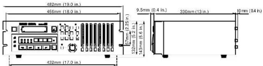
Size (including feet) 482 x 143 x 350 (mm) w x h x d 19 x 5.6 x 13.8 (in)
Weight 8.1 kg (17.8 lbs)
12.2.10 Power specifications
Power requirements USA/Canada 120 VAC, 60 Hz U.K./Europe 230 VAC, 50 Hz Australia 240 VAC, 50 Hz
Power consumption 34 W
Applicable Electromagnetic E4
Environment
Peak inrush current 16.5 A
Dynamic range >104dB DTRS-HR
(Fs=48kHz, 22k LPF and A- >95dB DTRS
weight)
Total harmonic distortion < 0.004% (DTRS-HR)
< 0.005% (DTRS)
Channel separation >90 dB at 1kHz
Wow and flutter Unmeasurable
0 dB u = 0.775 V rms, 0 dB V = 1.0 V rms
Changes in specifications and features may be made without notice or obligation
12.2.11 Audio specifications
Frequency response 20 Hz to 20 kHz±0.5dB
Signal-to-noise ratio >104 dB DTRS-HR
(Fs=48kHz, 22 k LPF and >100 dB DTRS
A-weight)
A
aborting the format process 28
ABS and timecode 52
ABS frame rate 52
ABS setting 53
ABS time 52
absolute and relative difference60
absolute difference
absolute time
see "ABS time"
adjusting parameter values 21
advanced output options 44
ALL ANALOG setting 31
ALL INPUT 14,36
ambient temperature 8
analog inputs 72
analog inputs (balanced) 16
analog inputs (unbalanced) 16
analog outputs 72
synchronizing with timecode 55
analog outputs (balanced) 16
analog outputs (unbalanced) 16
audio connections 17
Audio specifications 73
audio specifications 73
AUDIO1 menu 23
AUDIO2 menu 24
AUTO IN/OUT (OFFSET) key and indicator 14
AUTO MON 14, 36
auto play39
autolocation38
see "location points"
automatic park position setting59
automatic punch point setting 32
available recording and playback time 11
B
backup memory initialization69
balanced analog audio connections 17
basic operations 27
BER
see "Block Error Rate"
block error rate (BER) 68
bypassing timecode errors60
C
cables71
cancelling machine offset 48, 59
cancelling timecode offset 59
cassette types9
CHASE key 15
chase mode 48
chase to timecode 58
checking and editing and manually entering location points 38
checking drum time69
checking error rates 68
checking external timecode 57
checking head time69
checking location points 38
checking the frame mode of striped timecode 58
checking version numbers 69
cleaning the heads 68
CLEAR (PRE ROLL) key 14
clock source in a digital studio 8
condensation 9
condensation (dew)9
connections
digital audio 17
crossfade tim€1, 65
cursor keys 22
D
DA-3847
DA-8847
DA-9847
DATA/LEVEL knob 22
default values (resetting) 21
delaying tracks 39
dew warning 9
digital audio connections17
digital dubbing 50
digital I/O16
DIGITAL IN, OUT (COAXIAL) 16
digital input selection 29
Digital inputs and outputs 72
digital outputs
synchronizing with timecode 55
dither 31, 43
drum time 69
DTRS10
emulation 45
models (differences) 47
synchronization 47
synchronization (error messages) 51
dubbing 50
E
edit/pan setting mode40
editing location points 38
electrical considerations 9
emulation45
enabling and disabling MMC 62
environmental conditions 8
error rate68
external timecod57
external timecode source
F
fast linear timecode (LTC) output55
footswitch 16, 18
formatting27, 50
frame mode53
striped timecode58
frame rate53
ABS timing52
G
generating timecode 56
generator modes 56
grounding 9
H
head cleaning 68
head time 69
HR mode 7–8
emphasis 8
|
ID
see "machine ID"
IF-88SD SDIF-2 digital audio converter 71
IF-AE8 AES/EBU digital audio converter71
IF-TAD ADAT digital audio converter 71
"indirect" word syn£9
individual clock mode 51
individual recording while chasing timecode 60
input patchbay routing 30
input selection 29
input timecode display54
input word length 31
inputs and output specifications 72
inputs and outputs 72
installing the DA-78HR9
interrupting a rehearsal or punch recording 34
L
"Left" and "right" keys 22
line-up oscillator43
LOC 1 (MEMO 1) key 15
LOC 2 (MEMO 2) key 15
location 7
MEMO 1 and MEMO 2 38
location and playback 38
location points 38
auto play 38
auto-repeat 39
editing38
locating 38
setting pre-roll time38
LTC output 55
M
machine ID47, 58
master/slave settings47
setting48
timecode 58
machine offset 48, 65
maintenance menu 26
manually entering location points 38
master/slave settings47–48
master/slave settings (CHASE mode) 48
ME tapes 10
menu interface20
menu mode
exiting 21
menus 7, 21
sub-menus 21
meterballistics42
meter modes 42
meters 42
MIDI 7
connectors 15, 18, 72
control 62
Control Change 65
functions 18
ID 62
implementation cha67
machine control 18, 63
menu 25
MIDI timecode18
MIDI timecode connections 18
MMC 62
settings25
System Exclusive 65
timecode 18
MIXDOWN (LEVEL/PAN) key and indicator 15
mixdown mode40
MMC
bitmap array63
commands62
enable and disable 62
monitoring 7, 36
monitor mode summary 37
shuttle 36
MP tapes 10
MTC 18
MTC output 54
multiple DTRS units/8
N
nthesizing 56
0
offset
DTRS synchronization 48
setting 49
timecode 58
options 71
PW-88S (cable) 47
RC-808 remote control unit 71
RC-828 remote control unit 71
RC-898 remote control unit 71
TDIF-1EX extender box 71
oscillator 43
output
advanced options 44
patchbay 44
word length 44
overdubbing 31
P
parameter values, adjusting?
park position59
peak hold time 42
peak meters 15, 20
Physical specifications 73
physical specifications 73
pitch control
see "varispeed"
playback (repeat) 39
playback times 11
post-roll time
see also "pre-roll time"33
\~ IN (POWER IN)6
power cord 7
power specifications 73
power supply 9
powering the unit off and on 9
pre-roll and post-roll (punch) 33
pre-roll time
editing 33
location38
propagation delay 39
punch-in and punch-out 32
punch-in mode 35
exiting35
punch-ins
crossfade time\$1
interrupting 34
introduction 32
recording34
rehearsing 34
replaying 34
setting points 32
setting punch points 32–33
R
rack mounting 9
REC FUNCTION keys and indicators 15
REC MUTE (recording silence) 43
rec mute function43
rechasing timecode 60
recommended tapes 9
RECORD key 14
recording
emphasis 8
recording punch-ins 34
recording silence (REC MUTE) 43
recording the oscillator 43
recording time11
recording timecode 55
from external sources57
using the generator 56
recording timecode from external sources 57
recording while formatting 28, 51
rectangular dither 44
rehearsing punch-ins 34
relative difference60
relative humidity8
Remote control connectors 72
REMOTE IN 15, 18
REMOTE IN/SYNC IN 15
REMOTE PUNCH IN/OUT 16
Remote/sync connectors 72
REPEAT (MENU) key and indicator 15
repeat function 39
repeat play 39
replaying punched material 34
resetting parameters 21
restoring settings from tape45
s
sampling frequency 31
saving settings to tape 45
selecting a clock source 27–28
selecting dither settings 44
selecting input word length 31
selecting TC or ABS timing2
selecting the frame mode 53
selecting the timecode source 55
selecting timecode or absolute timing
setting a non-standard speed41
setting default parameter values21
setting location points 38
setting machine ID48
setting machine offset 48
setting machine offset "on the fly" 49
setting MEMO 1 and MEMO 2 "on the fly"38
setting punch points "on the fly" 32
setting punch points using the front panel33
setting punch points using the menus33
setting the location pre-roll time8
setting timecode offset "on the fly"59
settings
restoring from tape 45
saving to tape45
SHIFT key and indicator14
shift mode20
shifted keys 20
shuttle42
shuttle monitoring36, 42
shuttle muting36, 42
shuttle operations42
SHUTTLE/DATA knob 22
sine oscillator43
software upgrades 70
software version 69
software version numbers 69
SPDIF
connectors 18
input/output 16
Specifications72
STOP key 14
sub-frame values 22
sub-menus 21
sub-mixer 40
input sources 41
master level 40
setting levels and pan positions40
summary of monitor modes 37
synchronization
connections 18, 47
formatting 50
PW-88S cable 47
with other DA units47
with other DTRS units 47
synthesizing timecode from ABS timing56
SYSTEM menu23
T
tape brands 10
tape errors68
tape head cleaning 68
tape length 11
Tape recorder section 72
tape timecode52
tape types 9
DTRS 10
MP and ME 10
tapes
ME 10
MP 10
playback and recording times 11
TC chase men25
TC generator menu 25
TC menu24
TC time 52
TC timing52
TDIF-1 (DIGITAL I/O) 16
test tone43
timecode7, 52
ABS times 52
absolute and relative difference 60
bypassing errors 60
chasing 58
connections 16, 18
external 54, 57
external sources 57
fast LTC 55
frame mode 53
frame rate 53
from digital source 57
from tape 55
generator 55
input 54
input timing 54
LTC output 55
machine ID 58
MTC 18
offset 58–59
output 54
output during fast operations 55
output timing 55
park position 59
park position when chasing 59
rechasing 60
recording from external sources 57
selecting the source 55
synthesizing from ABS timing 53, 56
TC time 52
Timecode connectors 72
timecode output 54
timecode time
see "TC time"
track bouncing 30
track controls 15
track copy
enable 66
setup 66
track delay 39, 65
transport keys and controls 13
U
unbalanced analog audio connections 17
V
varispeed 7, 41
W
word clock connections 18
word length 31
word sync 16
Word sync terminals72
write-protecting cassette28
TASCAM
TEAC Professional Division
DA-78HR
TEAC CORPORATION
Phone: (0422) 52-5082 3-7-3, Nakacho, Musashino-shi, Tokyo 180-8550, Japan
TEAC AMERICA, INC.
Phone: (323) 726-0303 7733 Telegraph Road, Montebello, California 90640
TEAC CANADA LTD.
Phone: 905-890-8008 Facsimile: 905-890-9888 5939 Wallace Street, Mississauga, Ontario L4Z 1Z8, Canada
TEAC MEXICO, S.A. De C.V
Phone: 5-658-1943 Privada De Corina, No.18, Colonia Del Carmen Coyoacon, Mexico DF 04100
TEAC UK LIMITED
Phone: 01923-819699 5 Marlin House, Marlins Meadow, The Croxley Centre, Watford, Herts. WD1 8YA, U.K.
Phone: (03) 9644-2442 106 Bay Street, Port Melbourne, Victoria 3207, Australia
- TEAC Professional Division
- DA-78HR
- OWNER'S MANUAL
- IMPORTANT (for U.K. Customers)
- DO NOT cut off the mains plug from this equipment.
- TO THE USER
- CAUTION
- For the consumers in Europe
- WARNING
- IMPORTANT SAFETY INSTRUCTIONS
- CAUTION:
- "Note to CATV system installer:
- Table of Contents
- - Introduction to the DA-78HR
- - Front and rear panel features
- - Connections
- - Menu interface, etc.
- - Basic operations
- - Monitoring
- - Advanced operations
- - Synchronization with other DTRS units
- - Operations related to timecode
- - MIDI control
- - Maintenance, etc.
- - Options, specifications and reference
- Unpacking
- Features
- Using this manual
- NOTE
- Precautions and recommendations
- Clock source in a digital studio
- HR recording and emphasis
- Environmental conditions
- Installing the DA-78HR
- Electrical considerations
- Three-core power cord
- Powering the DA-78HR off and on
- Condensation
- Recommended tapes
- Tape brands
- Available recording and playback time
- General controls and indicators
- ① Power switch
- ② Tape loading slot and EJECT key
- ③ FORMAT/Fs key
- ④ HR MODE key
- ⑤ CLOCK key
- ⑥ Status indicators
- ⑦ Tape counter
- ⑧ PB CONDITION indicator
- Tape transport keys and controls
- ⑨ REW key
- ⑩ F FWD key
- ⑪ STOP key
- ⑫ PLAY key
- RECORD key
- DATA/LEVEL control
- System control keys
- ⑮ SHIFT key and indicator
- RHSL (DELAY) key and indicator
- ⑰ AUTO IN/OUT (OFFSET) key and indicator
- CLEAR (PRE ROLL) key
- ⑲ VARI SPEED / PITCH key and indicator
- ALL INPUT (▼) key and indicator
- ② AUTO MON ( ▲) key and indicator
- ②2 REPEAT (MENU) key and indicator
- ②3 CHASE (SUB MENU) key and indicator
- LOC 1 (MEMO 1) key
- ⑲ LOC 2 (MEMO 2) key
- MIXDOWN (LEVEL/PAN) key and indicator
- Track controls
- REC FUNCTION keys and indicators
- Peak meters
- Rear panel features
- REMOTE IN/SYNC IN
- MIDI IN/OUT/THRU
- SYNC OUT
- REMOTE IN
- REMOTE PUNCH IN/OUT
- TDIF-1 (DIGITAL I/O)
- TIME CODE (IN, OUT)
- WORD SYNC (IN, OUT, THRU)
- DIGITAL IN, OUT (COAXIAL)
- ANALOG INPUTS (unbalanced)
- ANALOG INPUTS (BALANCED)
- ANALOG OUTPUTS (unbalanced)
- ④1 ANALOG OUTPUTS (BALANCED)
- \~ IN
- Audio connections
- Balanced analog audio connections
- Unbalanced analog audio connections
- Digital audio connections
- SPDIF connectors
- Synchronization connections
- Word clock connections
- MIDI connectors (IN, OUT and THRU)
- Timecode connections
- MIDI timecode connections
- Connection to other TASCAM units
- REMOTE IN
- Footswitch
- Multiple DTRS units
- "Indirect" word sync
- The display
- Peak meters
- The SHIFT key
- Shifted keys
- Shift mode
- Menus and sub-menus
- Exiting menu mode
- Sub-menus
- Adjusting parameter values
- Resetting parameters to default values
- "Left" and "right" keys
- Sub-frame values
- Using the DATA/LEVEL knob to set values
- SYSTEM menu
- AUDIO1 menu
- AUDIO2 menu
- TC menu
- TC chase menu
- TC generator menu
- 4.10MIDI menu
- Maintenance menu
- Dedicated keys
- Formatting a tape
- Selecting a word clock source
- Formatting
- Aborting the format process
- Recording while formatting
- Recording the first tracks
- Preparing to record
- Selecting a clock source
- Write-protecting cassettes
- Recording the first tracks (i)
- Recording the basic tracks (ii)
- Replaying the first tracks
- Input selection
- Digital input selection
- Input patchbay routing
- To select another destination track, press that track's REC FUNCTION key and repeat the process.
- Track bouncing
- Returning to ALL ANALOG setting
- More on digital recording
- Sampling frequency and word length
- Selecting input word length
- Overdubbing
- Punch-in and punch-out
- Automatic punch point setting
- Setting punch points "on the fly"
- Setting punch points using the front panel
- Editing the pre-roll and post-roll times
- Rehearsing the punch-in
- Interrupting a rehearsal or punch recording
- Recording the punch-in
- Replaying the punched material
- Exiting punch-in mode
- ALL INPUT
- AUTO MON
- Shuttle monitor
- Enabling and disabling shuttle monitoring
- Shuttle muting
- Summary of monitor modes
- Autolocation
- Setting MEMO 1 and MEMO 2 "on the fly"
- Checking, editing and manually entering MEMO 1 and MEMO 2
- Setting the location pre-roll time
- Moving to MEMO 1 and MEMO 2
- Location and playback
- Repeat function
- To start repeat play
- Track delay
- Press and hold the SHIFT key for more than three seconds to exit the delay setting mode.
- Sub-mixer
- Entering mixdown mode
- Setting the master level
- Leaving edit/pan setting mode
- Setting levels and pan positions
- Setting the sub-mixer input sources
- Crossfade times
- Vari speed (pitch control)
- To set a non-standard speed
- Shuttle operations
- Shuttle monitoring
- Shuttle muting
- Meter modes
- Peak hold time
- Meter ballistics
- Sine oscillator
- Recording the oscillator
- 7.10REC MUTE (recording silence)
- Dither
- Selecting dither settings
- Advanced output options
- Output word length
- Output patchbay
- 7.13Emulation
- Saving settings to tape
- 7.15Restoring settings from tape
- Synchronization connections
- Machine ID and master/slave settings
- Differences between DTRS models
- Setting machine ID
- Master/slave settings (CHASE mode)
- Machine offset
- Setting machine offset
- Cancelling machine offset
- Setting machine offset "on the fly"
- An example of setting offsets
- Digital dubbing
- Synchronized formatting
- Recording while formatting
- Individual clock mode
- Error messages
- ABS and timecode
- ABS time
- Tape timecode
- Selecting TC or ABS timing
- Tape timecode mode
- TAPE TC setting
- ABS setting
- Selecting the frame mode
- Timecode input and output
- Showing input timecode
- Timecode input timing
- Timecode output
- MTC output
- Fast linear timecode (LTC) output
- Timecode output timing
- Recording timecode
- Selecting the timecode source
- Recording timecode using the generator
- Generator modes
- Synthesizing timecode from ABS timing
- External timecode sources
- Recording timecode from external sources
- Checking external timecode
- Checking the frame mode of striped timecode
- Chasing to timecode
- Machine ID and timecode
- Timecode offset
- Setting timecode offset
- Cancelling timecode offset
- Setting timecode offset "on the fly"
- Park position
- Automatic park position setting
- Absolute and relative difference
- Rechasing timecode
- Bypassing timecode errors
- Individual recording while chasing timecode
- MMC enable and disable
- Assigning a MIDI ID to the DA-78HR
- MMC commands and the DA-78HR
- 10.2MMC Bit Map Array
- 10.3MIDI Control Change
- 10.4MIDI System Exclusive
- Identity Reply
- TASCAM Exclusive messages
- Track delay
- Crossfade
- Machine offset
- Track Copy Setup
- Track Copy Enable
- Head and transport cleaning
- Every 350 to 400 hours
- Every 1000 hours (every third cleaning)
- To clean the heads and transport
- Checking error rates
- Checking drum time
- Backup memory initialization
- Checking version numbers
- Software upgrades
- Options for the DA-78HR
- RC-898 remote control unit
- RC-828 remote control unit
- RC-808 remote control unit
- IF-AE8 AES/EBU digital audio converter
- IF-88SD SDIF-2 digital audio converter
- IF-TAD ADAT digital audio converter
- TDIF-1EX extender box
- Cables
- 12.2Specifications
- Tape recorder section
- Analog inputs and outputs
- Digital inputs and outputs
- Remote/sync connectors
- Word sync terminals
- Timecode connectors
- MIDI connectors
- Remote control connectors
- Physical specifications
- Power specifications
- Audio specifications
- A
- B
- C
- D
- E
- F
- G
- H
- |
- ID
- L
- M
- N
- 0
- P
- R
- s
- T
- U
- V
- W
- TASCAM
- TEAC CORPORATION
Brand : TASCAM
Model : DA-78HR
Category : Audio recorder