
Töörö - Synthesizer Fred's Lab - Free user manual and instructions
Find the device manual for free Töörö Fred's Lab in PDF.


| Product Type | Hybrid polyphonic synthesizer module (digilog) |
| Polyphony | 6 voices, 4-part multitimbral |
| Sound Engine | 2 wavetable oscillators, analog FL A847 low-pass filter, digital shaper (LP/BP/HP), 2 LFOs, 2 AHDSR envelopes, arpeggiator, modulation matrix (8 sources), multi-FX |
| Memory | 100 user presets, 10 user multis |
| Dimensions | 160 mm x 100 mm x 60 mm |
| Weight | 350 g |
| Power | USB 5V ±5%, 350 mA maximum |
| Audio Outputs | 2 x 6.35 mm unbalanced jacks (main L/R), 2 x 3.5 mm TRS jacks (voices 1-4 individually) |
| MIDI Connectivity | DIN IN, DIN OUT, USB-B (MIDI over USB and power) |
| Audio Resolution | 44 kHz, 12-bit |
| Master Clock | MCU 80 MHz, USB 48 MHz, OSCs 792 kHz |
| User Interface | 4 encoders, 14 tactile switches, 2-digit 7-segment hex display, 12 LEDs, power switch |
| Multi-FX Types | Mono modulated delay, stereo chorus/flanger, stereo modulated line |
| Arpeggiator | MIDI-syncable with up, down, random, upx, downx modes and grid settings |
| Envelopes | 2 x AHDSR with additional hold stage, velocity and aftertouch modulation, multiple trigger modes |
| LFOs | 2 independent with triangle, saw, square, random, filtered random, and cross-modulation shapes; rise and phase control |
| Modulation Matrix | 8 sources (Env F, Env A, LFO 1, LFO 2, Mod Wheel, Pitch, Velocity, Aftertouch) each assignable to one destination |
| Filter Tuning | Automated procedure to calibrate analog FL A847 filters for minimal voice-to-voice variation |
| Firmware Update | Via USB MIDI; follow instructions at fredslab.net to avoid bricking |
| Accessories Included | Quickstart guide, USB cable (1 m) |
| Safety & Care | Use in dry environment; avoid liquids, drops, and aggressive solvents; use certified USB adapters; shielded cables for FCC compliance |
| Warranty | 3 years from purchase date against manufacturing defects; does not cover wear, misuse, or unauthorized modifications |
Frequently Asked Questions - Töörö Fred's Lab
User questions about Töörö Fred's Lab
0 question about this device. Answer the ones you know or ask your own.
Ask a new question about this device
Download the instructions for your Synthesizer in PDF format for free! Find your manual Töörö - Fred's Lab and take your electronic device back in hand. On this page are published all the documents necessary for the use of your device. Töörö by Fred's Lab.
USER MANUAL Töörö Fred's Lab
TÖÖRÖ module User and service Manual
Revision 1.1 EN - 28/05/2021 for Firmware V1.42 - 07/05/2021
![graph TD A["POWER"] --> B["USB - 5V"] B --> C["MIDI IN"] C --> D["MIDI OUT"] D --> E["1&2"] E --> F["3&4"] F --> G["LEFT"] G --> H["RIGHT"] I["INT"] --> J["OSC"] J --> K["FILTER"] K --> L["OPEN"] L --> M["LFO"] M --> N["AMP"] N --> O["TUNE"] P["COPY"] --> Q["OSC"] R["COPY"] --> S["FILTER"] T["COPY"]…](/content/2026/05/886830/images/b12a80de96bfdbb91922606cff5f261e562f22493edeb19a099d124a512b6a10.jpg)
FRÉDÉRIC MESLIN / FRED'S LAB
May31,2021
Introduction
Thank you very much for purchasing the T“o“or“o!
This is the second multitimbral synthesizer from Fred's Lab and our best attempt at hybrid polyphonic synthesis.
By carefully blending analog and digital technologies, mixing 1970's and 2020's electronics and pouring it in a compact and rugged package, the T"o"or"o was born.
With its 6 characterful voices, the wild FL A847 filters and an advanced delay on board, the T'o"or"o has high sonic potential, just release it and create!
Love from Germany
Fred, from Fred's Lab
Legal notices
Fred's Lab cannot be liable for erroneous information contained in this manual. The contents of this manual may be updated at any time without prior notice. We have put best effort to ensure the information provided here is useful and accurate. Fred's Lab extends no liabilities in regard to this manual other than those required by the local laws.
Fr'ed'eric Meslin Audioger"ate
Herwarthstraße, 20
53115 Bonn, Germany
info@fredslab.net
http://fredslab.net
Support requests
For support requests, you can reach me per e-mail at:
support@fredslab.net
or per post, using the previously mentioned company address.
For each support request, please include the instrument model, serial number and a precise description of the problem encountered with a maximum of details and supporting elements for a quick resolution.
Copyright information
This original manual, its content, including the graphics & descriptions are the property of Fred's Lab. No part of this manual should be reproduced other than for customer personal use and backup needs without a written permission from Fred's Lab.
Warranty
Fred's Lab warranty this product free of defects 3 years from its date of purchase.
This warranty covers product from manufacturing defects, when the product is used observing normal operating conditions. However, the warranty does not cover:
• Normal product wear-out
- Damages caused by failure to observe the rules of use
• Damages due to negligence of the user
- Products having been modified or repaired by the user or a third person
More information about product warranty can be found in the General Terms and Conditions of Sale document available at:
https://fredslab.net/en/terms.html
Special Thanks
I would like to thank the following persons for their contributions to this project:
- Panel and logo designs: Serge Beauchamp
- Kickstarter communication / Press kit: Alex Theakston
• Factory sounds: Espen Kraft - Quality insurance: Benoit Ruelle, Ren'e Schmidt, Pierre Studievic, Mathieu Meslin, Thomas Billiou, Oliver Rockstedt
- User manual: Oliver Rockstedt
• Audio demos: Laurent Pelletier, Fabien Labonde
And Fanny & Neal Homberger for their continuous support and their regular contributions.
This project has been made possible through the financial support from the Kickstarter Backers.
Precautions
Before plugging in the Töörö! and go rocking the World, have a sit and read this precautions through:
• Always use the device in a dry and warm environment
- Never drop the device or expose to too much pressure or vibration
- Never spill liquids or bath the device in beer
- Never clean the device with an aggressive solvent
- Only use certified USB power adapters to power the device
- Never wiggle the plugs to disconnect the cords
- Never connect the line outputs to the power outputs of an amplifier
- Only modify the unit at your own risk!
The Töörö! used in conjunction with headphones and speaker systems can produce very loud sounds in a wide range of frequencies.
Human hearing is very sensitive and can be damaged quickly. So watch out your hears and those of your audience!
Contents
1 Presentation 9
1.1 What is MIDI? 9
1.2 Remarks on polyphony 9
2 Requirements 9
2.1 An audio system ..... 9
2.2 A MIDI controller ..... 10
2.3 A USB power source ..... 10
2.4 Remarks on USB noise ..... 10
3 Instrument Setup 11
4 Instrument Operation 12
4.1 Connectors 12
4.2 Controls & Indicators ..... 13
4.3 Editing Parameters ..... 14
4.3.1 Parameter LEDs 14
4.3.2 Parameter Display 14
5 Preset & Multi Management 15
5.1 Selecting a Part ..... 15
5.2 Setting the MIDI Channel ..... 15
5.3 Selecting a Preset ..... 15
5.4 Saving a Preset 16
5.4.1 Overwriting the Current Preset 16
5.4.2 Saving a Preset to a Different Memory Location 16
5.5 Copying Presets.... 16
5.6 Initializing a Preset 16
5.7 Dumping a Preset via Sysex 16
5.8 Selecting a Multi ..... 17
5.9 Saving a Multi ..... 17
5.9.1 Overwriting the Current Multi 17
5.9.2 Saving a Multi to a Different Memory Location ..... 17
5.10 Copying Multis 18
5.11 Initializing a Multi 18
5.12 Dumping a Multi via Sysex 18
6 Preset Parameters 19
6.1 Overview 19
6.2 Voice Mode 19
6.3 Oscillators....20
6.3.1 Wave 20
6.3.2 Table 20
6.3.3 Coarse Tune 21
6.3.4 Fine Tune 21
6.3.5 FM Amount 22
6.3.6 FM Rate 22
6.3.7 Level 22
6.3.8 Sync 22
6.4 Extra 23
6.4.1 Noise Level 23
6.4.2 Ringmodulator Level 23
6.5 Filter 24
6.5.1 Cutoff....24
6.5.2 Resonance 24
6.5.3 Env F Amount 24
6.5.4 LFO 1 Amount ..... 24
6.5.5 Pitch Tracking 25
6.5.6 Aftertouch Amount 25
6.6 Shaper 26
6.6.1 Cutoff Frequency 26
6.6.2 Resonance 26
6.6.3 Env A Amount 26
6.6.4 LFO 2 Amount ..... 26
6.6.5 Pitch Tracking 27
6.6.6 Mode 27
6.7 LFOs 28
6.7.1 Shape 28
6.7.2 Speed 28
6.7.3 Rise 29
6.7.4 Phase 29
6.8 Envelopes 30
6.8.1 Attack Time 30
6.8.2 Decay Time 30
6.8.3 Sustain Level 30
6.8.4 Release Time 31
6.8.5 Velocity Amount 31
6.8.6 Hold Time 31
6.8.7 Aftertouch Amount 31
6.8.8 Trigger Mode 31
6.9 Amplifier 32
6.9.1 Level 32
6.9.2 Pan 32
6.10 Arpeggiator 33
6.10.1 Mode 33
6.10.2 Grid 33
6.10.3 Tempo 34
6.10.4 Hold 34
6.11 Modulation Matrix 35
6.11.1 Entering the Matrix Programming Mode 35
6.11.2 Programming a Modulation Assignment ..... 35
6.11.3 Replacing a Modulation Assignment 35
6.11.4 Clearing a Modulation Assignment ..... 35
6.11.5 Exiting the Matrix Programming Mode ..... 35
6.11.6 Modulation Sources ..... 36
6.11.7 Modulation Destinations ..... 36
6.11.8 Default Assignments 36
6.11.9 Example 1: Applying LFO 1 Modulation on Osc 1 Pitch ..... 37
6.11.10 Example 2: Applying Pitch Modulation on Amplifier Pan ..... 37
7 Multi Parameters 38
7.1 Overview....38
7.2 Parts Mixer 38
7.3 Multi FX 39
7.3.1 Length 39
7.3.2 Feedback 39
7.3.3 Mix 39
7.3.4 Mode 39
7.3.5 Speed 40
7.3.6 Depth 40
8 Filter Tuning 41
9 Firmware Update 41
10 Restoring the Factory Presets 41
11 Specifications 42
11.1 Sound Engine 42
11.1.1 General 42
11.1.2 Oscillators 42
11.1.3 Filter 42
11.1.4 Shaper 42
11.1.5 Envelopes 42
11.1.6 LFOs 42
11.1.7 Arpeggiator 42
11.1.8 DCA 43
11.1.9 Multi FX 43
11.2 Memory 43
11.3 Line Outputs 43
11.4 Audio Resolution 43
11.5 Master Clocks 43
11.6 Power 43
11.7 Connectors 43
11.8 User Interface 44
11.9 Dimensions & Weight 44
11.10Mechanics 44
11.11Accessories 44
12 MIDI Implementation 45
12.1 Channel Voice Messages 45
12.1.1 Note Off 45
12.1.2 Note On 45
12.1.3 Polyphonic Aftertouch 45
12.1.4 Controller Change 45
12.1.5 Program Change 46
12.1.6 Channel Aftertouch 46
12.1.7 Pitch Bend .... 46
12.2 System Real Time Messages ..... 46
12.2.1 Clock Start 46
12.2.2 Clock Continue ..... 46
12.2.3 Clock Stop 47
12.2.4 Clock Tick 47
12.2.5 Active Sensing 47
12.3 MIDI CC Assignments ..... 48
13 Sysex Implementation 50
13.1 Requests 50
13.1.1 Multi Request 50
13.1.2 Preset Request 50
13.1.3 Preset Parameter Request ..... 50
13.1.4 Multi Parameter Request ..... 51
13.2 Dumps 52
13.2.1 Multi Dump 52
13.2.2 Preset Dump 53
13.2.3 Preset Parameter Dump 56
13.2.4 Multi Parameter Dump 56
13.2.5 Data Packing 56
14 Schematics 58
15 Norms 68
15.1 Europe: CE 68
15.2 Canada: Interference Regulation ..... 69
15.3 USA: FCC Information 69
1 Presentation
The Töörö is a 6-voice polyphonic, 4-part multi-timbral, hybrid "digilog" MIDI sound module.
- Polyphonic means it can play several notes at the same time.
- Multi-timbral means it can play several instruments at the same time.
- Digilog means the sound is created using audio algorithms and then converted into the analog domain for further processing.
- MIDI sound module means it needs a MIDI controller to generate sound.
1.1 What is MIDI?
MIDI stands for Musical Instrument Digital Interface.
It is a technical standard allowing music instruments to communicate and be used in concerto. It defines a protocol, messages, a digital interface and cables / connectors formats. A MIDI connection carries notes, controller changes, clocks and various configuration data.
The Töörö is a hybrid instrument. It initially computes the sounds using mathematical models and algorithms, executed by a powerful ARM micro-processor, which are then converted into analog domain and shaped by an FL A847 low-pass filter.
1.2 Remarks on polyphony
The 6-voice polyphony is the absolute maximal number of notes that can be played at the same time. If you try to play more notes simultaneously, the older voices will be muted and reused for newer notes. This mechanism is called "voice-stealing" and will result in audio artifacts or parts of your music not being played when triggered. In order to avoid it, keep in mind the module limitations while composing your music.
2 Requirements
To play with the T"o"or"o you need:
- An audio system with line-level inputs
• A MIDI controller, a sequencer or a computer
• A USB power source
2.1 An audio system
can be a HiFi stereo system, a power mixing desk connected to speakers or a pair of active speakers.
2.2 A MIDI controller
can be any master keyboard, wind controller, surface... that sends MIDI notes. You can also attach the instrument to a hardware or software MIDI sequencer. It can run on a computer, a laptop or a tablet/smartphone. You may need a dedicated external MIDI interface or just use the USB connection.
2.3 A USB power source
can be a USB host, a power bank or a USB wall adapter/charger. Never use cheap USB chargers that can be very noisy.
2.4 Remarks on USB noise
If you keep hearing irritating hum and noise when the Töörö is connected via USB, you may experience a USB ground loop problem. Fortunately, there are several solutions to overcome this problem.
Solution 1:
- Use another USB power source (power bank or wall adapter)
- Connect the instrument to the computer with a MIDI DIN cable
Solution 2:
• Use a USB galvanic isolator

Example: Olimex USB-ISO module
https://www.olimex.com/Products/USB-Modules/USB-ISO
MIDI DIN connections are, by design, prevented from ground loop problems. It is the preferred solution to avoid these annoying issues.
3 Instrument Setup
Step 1: Audio
Connect the Töörö line-level outputs (left & right) to your audio system inputs using two 6.35mm unbalanced jacks.
Step 2: MIDI
Connect the Töörö MIDI DIN input (MIDI IN) to your MIDI compatible controller or sequencer/computer using a MIDI DIN cable.
or
Connect the USB port (USB - 5V) to your computer, laptop, tablet or smartphone.
Step 3: Power
If not already done in the previous step, connect the Töörö power input (USB - 5V) to your power source of choice.
Press the power switch on the rear panel to power up the T"o"or"o.
Step 4: Audio system
Switch on you audio system, adjust the volume and play some notes!
4 Instrument Operation
Once the instrument is properly installed and you can hear some sounds when playing notes, let's have a good look at its panel:

4.1 Connectors
A USB - 5V
This is the USB-B connector for both power and MIDI over USB function. It must be attached to a source to power up the T"o"or"o.
B MIDI IN
This is the MIDI DIN input connector for a MIDI compatible controller or sequencer. It should be attached to a MIDI DIN output connector of an other device.
©MIDI OUT
This is the MIDI DIN output connector to be connected to a sequencer, computer or subsequent machines. All incoming messages that are not parsed by the Töörö are forwarded to this output.
D VOICES 1&2 / 3&4
These are separate TRS jacks hardwired to voices 1-4 for individual processing. Signal of voices 1/3 will appear on the tip, voices 2/4 on the ring of the connector. Note that the voices are not cut from the main outputs when a cable is plugged in.
E F LEFT & RIGHT
These are the main outputs to be connected to a mixing desk, audio interface of power speaker system.
4.2 Controls & Indicators
①Power Switch
Switches the power on or off.
② Module Buttons & LEDs
Selects the module edited by the parameter encoders. Pressing the same buttons several times cycles through all available modules of a section. The LED color shows which module is currently selected corresponding to the panel labeling.
③ SYSTEM Button
Allows access to the advanced functions. This button is used in conjunction with the parameter encoders and the module buttons.
④ALT Button & LED
Used to access the alternate functions and synthesis parameters labelled in inverse printing. Pressing this button toggles between normal and alternate mode. Alternate mode is indicated with the LED lit.
⑤VOL/BAL Button
Holding this button while turning one of the encoders sets the volume or balance for a part. In normal mode, volume is set. To set the balance, enable the alternate mode via the ALT button.
⑥ POLY LED
If lit, the currently selected part is in polyphonic mode. Otherwise, the part is set to monophonic mode. Double-click the VOL/BAL button to toggle the mode.
⑦ Parameter Encoders & LEDs
Changes the value of sound or system parameters.
⑧PGM LED
Indicates if modulation matrix programming mode is enabled.
⑨ EXIT Button
Exits matrix programming mode and returns to normal operation. Also, holding the EXIT button and pressing the PRESET button reloads the currently saved preset / multi (depending on ALT), discarding all modifications made.
10 Sources Buttons
Enters matrix programming mode and selects the source to modulate a sound parameter. If alternate mode is enabled via the ALT button, a second set of sources can be selected and assigned.
⑪ PRESET/MULTI Button
Loads and saves presets and multis. Pressing the button momentary, loads the next preset. Holding the button down for more than one second will save the current preset or multi with all its modifications.
127-segment Display
Shows the current preset or multi number. While editing a parameter, the display will show its current value for some time. To indicate negative parameter values, the dot after the first digit will be lit. Also, when MIDI data is received, the dot after the second digit will flash. When selecting a module for editing, the display will briefly indicate which module is edited.
4.3 Editing Parameters
To edit parameters, use the 4 encoders at the bottom row of the Töörö. Which parameters are currently edited, depends on the selection of the module via the module buttons, if alternate mode is enabled via the ALT button or the SYSTEM button is held down.
4.3.1 Parameter LEDs
The LEDs above the encoders give a rough idea about the parameters value by showing different colors and brightness:
- When a parameter is set to 0, the LED is off.
- Unipolar parameters start with yellow for smaller values, blending into red on higher values.
- On bipolar parameters, negative values are shown in green, positive values are shown in red.
Color blind users should instead rely on the values shown on the display when turning the encoders.
4.3.2 Parameter Display
Whenever a parameter is changed via an encoder, the display shows its current value for a short time and then changes back to the preset or multi number.
To show the values in full resolution on the 2-digit display, most numeric parameters of the Töörö are shown as hexadecimal values. Negative values are indicated by a dot after the first digit.

Hcx: -0x2A
Decimal: -42

Hex: 0x43
Decimal: 67
5 Preset & Multi Management
The Töörö is a multi-timbral device that can store 100 presets and 10 multis. All memory locations can be overwritten by the user, so the factory patches can be overwritten.
An important concept to understand is that there is no separation between preset and multi mode, the Töörö always operates in multi mode.
- A preset is a single sound with a set of parameters for oscillators, filter, shaper, LFOs, envelopes, amplifier, arpeggiator and modulation matrix.
- For operations on presets, the alternate mode must be disabled. Make sure that the ALT LED is not lit.
- A multi is a set that references 4 presets as parts, a mixer with volume and balance, the MIDI channel settings and an fx section.
- For operations on multis, the alternate mode must be enabled. Make sure that the ALT LED is lit.
5.1 Selecting a Part
Before selecting or editing a preset, it is important to select the part currently edited. By default, part 1 is selected.
Press and hold the SYSTEM button. Then use the first parameter encoder labelled PART to select the part. The display will show P1..P4 while the encoder is turned.

Part selection 1..4
5.2 Setting the MIDI Channel
You can set a separate MIDI channel for each part to receive notes and other messages from an external keyboard, computer or sequencer. In addition, omni mode can be selected to receive MIDI data from all channels.
Press and hold the SYSTEM button. Then use the second parameter encoder labelled CHANNEL to select the midi channel. The display will show 01..16 or OM while the encoder is turned.

Channel 1..16

Omni mode
Note: when omni mode is selected, channel 1 is used to transmit parameter changes.
5.3 Selecting a Preset
There are 2 ways to select a preset:
- Press the PRESET button to increment the preset number by one.
- Press and hold the SYSTEM button. Then use the fourth parameter encoder labelled PRESET to increment or decrement the preset number.

Preset selection 0..99
5.4 Saving a Preset
5.4.1 Overwriting the Current Preset
To save an edited preset onto the current memory location, press and hold down the PRESET button until the display starts to blink. When the button is released, the preset will be saved, replacing the data stored previously.
5.4.2 Saving a Preset to a Different Memory Location
Saving a preset to a different location can be done by copy & paste utilizing a temporary buffer.
- Press and hold the SYSTEM button. Then press the Module button labelled FILTER. This button also has a secondary vertical label COPY left to it.
- The preset is now stored inside a temporary buffer.
- Select the destination preset to be overwritten as described above under Selecting a Preset.
- Press and hold the SYSTEM button. Then press the Module button labelled ENV. This button also has a secondary vertical label PASTE left to it.
- The preset previously stored in the temporary buffer is now recalled.
- Press and hold down the PRESET button until the display starts to blink. When the button is released, the preset will be saved.
5.5 Copying Presets
Presets can be copied to another location via copy & paste in a similar way as described above under Saving a Preset to a Different Memory Location.
5.6 Initializing a Preset
To initialize a preset, press and hold the SYSTEM button and then press the Module button labelled OSC. This button also has a secondary vertical label INIT left to it. Initializing resets all sound parameters to their default values.
5.7 Dumping a Preset via Sysex
Preset data can only be dumped over USB MIDI to be stored on an external computer or sequencer.
To dump a preset over USB MIDI, press and hold the SYSTEM button and then press the Module button labelled LFO. This button also has a secondary vertical label DUMP left to it.
You can dump back a preset from your computer or sequencer at any time. The T“o”or“o” will process any received dump without any prerequisites.
5.8 Selecting a Multi
There are 2 ways to select a multi:
- When alternate mode is selected via the ALT button, the multis can be cycled through by pressing the PRESET button repeatedly.
- Press and hold the SYSTEM button. Then use the third parameter encoder labelled MULTI to increment or decrement the multi number.
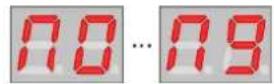
Multi selection M0..M9
5.9 Saving a Multi
First, make sure that alternate mode is enabled via the ALT button.
5.9.1 Overwriting the Current Multi
To save a multi onto the current memory location, press and hold down the PRESET button until the display starts to blink. When the button is released, the multi will be saved, replacing the data stored previously.
5.9.2 Saving a Multi to a Different Memory Location
Saving a multi to a different location can be done by copy & paste utilizing a temporary buffer.
- Press and hold the SYSTEM button. Then press the Module button labelled FILTER. This button also has a secondary vertical label COPY left to it.
- The multi is now stored inside a temporary buffer.
- Select the destination multi to be overwritten as described above under Selecting a Multi
- Press and hold the SYSTEM button. Then press the Module button labelled ENV. This button also has a secondary vertical label PASTE left to it.
• The multi previously stored in the temporary buffer is now recalled.
- Press and hold down the PRESET button until the display starts to blink. When the button is released, the multi will be saved.
5.10 Copying Multis
Multis can be copied to another location via copy & paste in a similar way as described above under Saving a Multi to a Different Memory Location.
5.11 Initializing a Multi
To initialize a multi, while in alternate mode, press and hold the SYSTEM button and then press the Module button labelled OSC. This button also has a secondary vertical label INIT left to it. Initializing resets all multi parameters to its default values.
- Part 1 will be set to preset 00 on MIDI channel 1.
- Part 2 will be set to preset 01 on MIDI channel 2.
- Part 3 will be set to preset 02 on MIDI channel 3.
• Part 4 will be set to preset 03 on MIDI channel 4.
• Volume is set to maximum for all parts.
• Balance is set to center for all parts. - The FX mix level is set to minimum / disabled
5.12 Dumping a Multi via Sysex
Multi data can be dumped over USB MIDI to be stored on an external computer or sequencer.
To dump a multi over USB MIDI, while in alternate mode, press and hold the SYSTEM button and then press the Module button labelled LFO. This button also has a secondary vertical label DUMP left to it.
You can dump back a multi from your computer or sequencer at any time. The T"o"or"o will process any received dump without any prerequisites.
Important: keep in mind that multi data does not contain any information about the sound parameters. You have to transfer these separately via preset dumps.
6 Preset Parameters
6.1 Overview
T“o”or“o overall preset structure
| PRESET | ||||
| •NAME Name of the Preset in 32 ASCII characters •TUNE Master tuning in cents •BENDRANGE Pitch bend range in semitones •USERTABLE Wave references for user tables 1 & 2 | OSC •WAVE Position in the wave table from 0 to 4 •COARSE Coarse pitch tuning -36 to +36 semitones •FM AMOUNT Amount of phase modulation from the FM operator •LEVEL Oscillator output level | •TABLE Wave table selection T1-T8, user, random per note, random per chord •FINE Fine pitch tuning -100 to +100 cents •FM RATE Rate of the FM operator based on oscillator pitch •SYNC Time scaling of waveforms | LFO 1&2 •SHAPE Triangle, saw-up, saw-down, square, MW, random, filtered random, LFO1 x LFO2 •RISE Oscillation level rising time | •SPEED Oscillation rate of the LFO •PHASE Free, random, 0, 90, 180, 270 |
| FILTER •CUTOFF Cutoff frequency of LP filter •RESO Amount of resonance •ENV. F AMOUNT Influence of filter envelope | •TRACK Pitch tracking of the cutoff •AFTERTOUCH Influence of MIDI aftertouch •LFO 1 AMOUNT Influence of LFO1 on cutoff | ARP •MODE off, up, down, random, upx, downx modes •TEMPO Internal tempo 64 - 320 bpm | •DIVISION 48, 32, 24, 16, 12, 8, 6, 3, 2, 1 MIDI ticks •HOLD on / off | |
| SHAPER •CUTOFF Cutoff or center frequency •RESO Q or gain amount •ENV. A AMOUNT Influence of amp envelope | •TRACK Pitch tracking of the cutoff •MODE Shaper mode, LP, BP & HP •LFO 2 AMOUNT Influence of LFO2 on cutoff | AMP •LEVEL Sound overall level | •PAN Sound stereo panning | |
| EXTRA •NOISE White noise level | •O1xO2 Amount of ring modulation | MOD. MATRIX •EF AMOUNT Amount of filter envelope •EA AMOUNT Amount of amplifier envelope •L1 AMOUNT Amount of LFO1 •L2 AMOUNT Amount of LFO2 •WHEEL AMOUNT Amount of MIDI mod. wheel •PITCH AMOUNT Amount of MIDI pitch •VELO AMOUNT Amount of MIDI velocity •AFTER AMOUNT Amount of MIDI aftertouch | •EF TARGET Parameter being modulated •EA TARGET Parameter being modulated •L1 TARGET Parameter being modulated •L2 TARGET Parameter being modulated •WHEEL TARGET Parameter being modulated •PITCH TARGET Parameter being modulated •VELO TARGET Parameter being modulated •AFTER TARGET Parameter being modulated | |
| ENV F&A •ATTACK TIME Time for env. to rise •DECAY TIME Time for env. to decay •SUSTAIN LEVEL Envelope sustain level •RELEASE TIME Time for env. to release | •VELOCITY Effect of velocity •HOLD TIME Hold time after attack phase •AFTERTOUCH Effect of aftertouch •TRIGGER MODE Always, never, continue | |||
Notes:
- The preset name is only accessible by Sysex messages.
- The Tune and Band Range parameters are only accessible via Sysex and MIDI CC messages.
6.2 Voice Mode
Each preset of the Töörö can be played in monophonic or polyphonic mode. To toggle the mode, double-click the VOL/BAL button. If polyphonic mode is selected, the POLY LED is lit.
In monophonic mode, each part is played by a single dedicated voice. The voice number corresponds to the part number, e.g. part 1 uses voice 1, part 2 uses voice 2 etc. This way, each part appears as a separate signal at the Voices Outputs, so it can be processed and mixed individually.
In monophonic mode, note priority is "last played" for new notes, and "highest" for re-triggered notes.
6.3 Oscillators

The Töörö has two identical wavetable oscillators that build the heart of the sound engine. Each oscillator generates a blended waveform that is determined by the content of the selected wavetable. In addition, FM modulation and auto-sync is possible within a single oscillator to produce alterations of the harmonic content.

To access the oscillators parameters, press the OSC module button. If you press the button more than once, the selection will cycle between Osc 1 and Osc 2. The LED color indicates which oscillator is selected:

Osc 1

Osc 2
In addition, the display will show the selected oscillator briefly:

Osc 1

Osc 2
In normal mode, the Wave, Coarse Tune, FM Amount and Level parameters can be edited via the first and second encoder. To edit the Table, Fine Tune, FM Rate and Sync parameters, alternate mode has to be enabled via the ALT button.
6.3.1 Wave
Sets the play position inside the selected wavetable. You can modulate this parameter via the modulation matrix in order to bring movement into your sound.
6.3.2 Table
This parameter selects the wavetable that is used by the oscillator. In conjunction with the Wave setting, it is the most important control to define the basic tone.
Each wavetable consists of a combination of 4 waveforms that are blended to create a smooth transition. The following 16 waveforms are available to build these combinations:
- Sawtooth
- Square
- Triangle
- Sine
- Blue Noise
- Brown Noise
- Metal overtones
-
Bell like
-
Double Saw
- Double Square
- Organ,
- Prime numbers
- Formant A
- Formant E
- Formant O
- Grin
There are 8 factory wavetables and one user wavetable to choose from:


Basic Sawtooth → Square → Triangle → Sine
Bright Blue Noise → Brown Noise → Metal Overtones → Bell-like
Full Double Saw → Double Square → Organ → Prime Numbers
Formants Formant A → Formant E → Formant O → Grin
Mix 1 Sawtooth → Organ → Bell-like → For- mant E
Mix 2 Triangle r → Grin → Sine → Blue Noise
Mix 3 Formant A → Brown Noise → Formant O → Prime Numbers
Mix 4 Metal Overtones → Double Square → Bell-like → Double Saw
User Free combination of waveforms
Random per Note Random combination generated on each played note
Random per Chord Random combination generated on each played chord
Each oscillator has its own user table. It is initialized with the content of Basic for Osc 1 and Bright for Osc 2.
There are two ways to change the content of the user wavetable:
- By sending a sysex command that configures the entries.
- By selecting the Random per note or Random per Chord wavetable and switch back to the User setting. Doing so will keep the last randomly generated combination. You can repeat this method several times until you are satisfied with the result.
6.3.3 Coarse Tune
Sets the pitch of the oscillator in semitones within a +/-3 octave range.
6.3.4 Fine Tune
Sets the fine pitch of the oscillator. It covers a range of +/-100 cents of a semitone.
6.3.5 FM Amount
The FM feature offers a phase modulation that uses the selected wave as carrier and a sine wave as modulator. This parameter sets the amount of modulation that is applied to the carrier.
6.3.6 FM Rate
Sets the frequency of the modulator sine wave for the phase modulation. The frequency is based on note pitch, using the following ratios:
- For negative values: freq / (1 - rate / 16)
- For positive values: freq * rate / 4
6.3.7 Level
Sets the mix level of the oscillator's output.
6.3.8 Sync
This parameter sets the auto-sync feature. It sounds like hard-sync and works by shorting and scaling the waveform, while keeping the note original pitch. A range of 1 to 15 waveform cycles can be set for the sync feature.
6.4 Extra

This module offers two additional signal sources that can be mixed with the oscillators before being routed to the shaper.

To access the extra parameters, press the FILTER module button. If you press the button more than once, the selection will cycle between filter and shaper. The extra module's parameters are accessible in both cases.
In normal mode, the Noise Level can be edited via the fourth encoder. To edit the Ringmodulator Level, alternate mode has to be enabled via the ALT button.
6.4.1 Noise Level
Sets the mix level of the white noise generator's output.
6.4.2 Ringmodulator Level
Sets the mix level of the ring modulator. The ring modulator multiplies the output of the two oscillators and generates a signal that contains the sum and the difference of the source signals. You can use this to get metallic timbres.
6.5 Filter

This module is one of the main sound-shaping components of the Töörö and is built upon a discret analog design, the FL A847 optocoupled resonant filter. It offers a 12db/octave low-pass with a unique sound.

To access the filter parameters, press the FILTER module button. If you press the button more than once, the selection will cycle between filter and shaper. The LED color indicates which module is selected:
Filter Shaper
In addition, the display will show the selected module briefly:


Filter Shaper
Make sure that the filter module is selected.
In normal mode, the Cutoff, Resonance and Env F Amount parameters can be edited via the first, second and third encoder. To edit the Pitch Tracking, After-touch Amount and LFO 1 Amount parameters, alternate mode has to be enabled via the ALT button.
6.5.1 Cutoff
The cutoff frequency sets the point at which the signal is split into two bands. Frequencies below that point will remain unaffected, while frequencies above will be attenuated progressively.
6.5.2 Resonance
In a resonant filter, frequencies around the cutoff point can be emphasized. This is what this parameter is for. The more the value is increased, the more the sound will get a nasal character that will turn into a ringing at higher settings. When fully raised, the filter will run into self-oscillation, producing a tone with a pitch tuned to the cutoff frequency.
6.5.3 Env F Amount
Determines how much the filter envelope (Env F) affects the cutoff frequency. Use this to shape the harmonic content over time in order to make your sound feel more alive.
6.5.4 LFO 1 Amount
Sets the amount of LFO 1 modulation on the cutoff frequency.
6.5.5 Pitch Tracking
This parameter allows the cutoff frequency to follow the pitch of the played notes. The effective pitch is calculated from the note number but also includes any modulation via the pitch wheel. The reference note number where modulation is unaffected is 36. The range of this parameter reaches from -200% to +200%. A setting of 10 in the display corresponds to a tracking of +100%, making the cutoff frequency follow the notes on the keyboard.
6.5.6 Aftertouch Amount
Sets the amount of modulation that is applied by the keyboard aftertouch.
6.6 Shaper

The shaper is a module located right after the mixer stage and allows additional processing before the signal is routed to the analog filter. It offers a multimode filter that can be configured as low-pass, band-pass or high-pass.

To access the shaper parameters, press the FILTER module button. If you press the button more than once, the selection will cycle between filter and shaper. The LED color indicates which module is selected:
Filter Shaper
In addition, the display will show the selected module briefly:


Filter Shaper
Make sure that the shaper module is selected.
In normal mode, the Cutoff, Resonance and Env A Amount parameters can be edited via the first, second and third encoder. To edit the Pitch Tracking, Mode and LFO 2 Amount parameters, alternate mode has to be enabled via the ALT button.
6.6.1 Cutoff Frequency
Sets the frequency at which the separation between pass band and attenuation band takes place.
- In low-pass mode, all frequencies above the cutoff frequency are attenuated.
- In band-pass mode, the cutoff frequency can be seen as center frequency. A band around this center frequency is kept unaffected, while the rest outside will be attenuated.
- In high-pass mode, all frequencies below the cutoff frequency are attenuated.
6.6.2 Resonance
- In low-pass or high-pass mode, this parameter creates an adjustable "bump" that accentuates the frequencies around the cutoff frequency.
- In band-pass mode, it adjusts the size of the band around the center frequency.
6.6.3 Env A Amount
Determines how much the amplifier envelope (Env A) affects the cutoff frequency. Use this to achieve a natural progression of the filter that corresponds to the volume of the signal.
6.6.4 LFO 2 Amount
Sets the amount of LFO 2 modulation on the cutoff frequency.
6.6.5 Pitch Tracking
This parameter allows the cutoff frequency to follow the pitch of the played notes. The effective pitch is calculated from the note number but also includes any modulation via the pitch wheel. The reference note number where modulation is unaffected is 36. The range of this parameter reaches from -200% to +200%. A setting of 10 in the display corresponds to a tracking of +100%, making the cutoff frequency follow the notes on the keyboard.
6.6.6 Mode
Switches between low-pass, band-pass and high-pass mode.


Low-pass Band-pass High-pass
6.7 LFOs

The Töörö has 2 independent LFOs that can be used for various modulation purposes.

To access the LFO parameters, press the LFO module button. If you press the button more than once, the selection will cycle between LFO 1 and LFO 2. The LED color indicates which LFO is selected:

In addition, the display will show the selected LFO briefly:


LFO 1 LFO 2
In normal mode, the Shape and Speed parameters can be edited via the first and second encoder. To edit the Rise and Phase parameters, alternate mode has to be enabled via the ALT button.
6.7.1 Shape
This parameter sets the waveform generated by the LFO.

Triangle
Ramp up, rising sawtooth
Ramp down, falling sawtooth
Square
M-shaped wave
Random steps, Sample & hold
Slew, like random but smoothed steps for continuous output
Amplitude modulation, product of a triangle wave and the other LFOs output
6.7.2 Speed
The speed parameter sets the LFO frequency. It covers a large range from 20 seconds up to 250Hz. The lower settings can be used for very slow, nearly unnoticeable movements, whereas the faster settings allow the LFO to be used as an additional FM audio source.
6.7.3 Rise
Sometimes it's not desirable to have the LFO at its full modulation after a note is played, but gradually fading it in. This is what the rise parameter does. It allows you to ramp up the modulation depth slowly up to 18 seconds.
6.7.4 Phase
The LFO can either be free-running or starting at a certain phase position after a note is played. A free running LFO is very interesting in mono mode and when using arppegio, as it allows a continuous progression of parameters for notes played in a sequence. A key-synced LFO allows to get more predictable results. Additionally, there is a random phase setting that is especially useful at low speeds.

Free running Random 0


。

90°

180°

270°
6.8 Envelopes

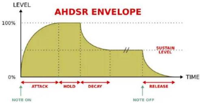
The Töörö has 2 independent envelopes that are designated for filter and amplifier modulation in first place, but can also be used for other modulation purposes. In addition to the standard ADSR-type envelopes, the Töörö offers an additional hold stage on both envelopes after the attack. Also, the sustain level can be modulated via aftertouch. The envelope times cover a range from 1ms to 18s for all parameters.

To access the envelope parameters, press the ENV module button. If you press the button more than once, the selection will cycle between filter envelope (Env F) and amplifier envelope (Env A). The LED color indicates which envelope is selected:

Env F

Env A
In addition, the display will show the selected envelope briefly:

Env F

Env A
In normal mode, the Attack, Decay, Sustain and Release parameters can be edited via the encoders. To edit the Velocity, Hold, Aftertouch and Trigger parameters, alternate mode has to be enabled via the ALT button.
6.8.1 Attack Time
Sets the time to rise the envelope signal from 0 to the maximum value after the envelope is triggered.
6.8.2 Decay Time
Sets the time required by the envelope signal to fall from the maximum to the sustain level.
6.8.3 Sustain Level
Sets the destination level that is reached at the end of the decay stage.
6.8.4 Release Time
Sets the time to fall from the sustain level to 0 after the trigger is released.
6.8.5 Velocity Amount
This parameter allows to control the overall modulation amount of the envelope via the note velocity. If set to 0, velocity has no effect on the envelope depth. If set to higher values, the amount of velocity sensitivity gradually increases.
6.8.6 Hold Time
The Töörö's envelopes have an additional hold stage, whose time can be controlled by this parameter. Setting its value to 0 completely disables the hold stage and the envelope works like a normal ADSR envelope. Increasing the parameter, introduces a hold time after the attack stage where the signal is kept at maximum before the decay stage is entered.
6.8.7 Aftertouch Amount
To offer more control over the sustain stage, its level can be modulated via aftertouch. This parameter defines how much the sustain level is affected by the aftertouch amount. If set to 0, aftertouch has no effect and sustain works in a normal way. On higher settings, the sustain is increasingly affected by the keyboard aftertouch.
6.8.8 Trigger Mode
The trigger mode sets the behaviour of the envelope when a new note is started while it is still running on a previous note.

Always restart from the attack stage with level 0.
Never retrigger. Stay at whatever level/stage it was before the voice was reused.
Continue. Always restart in the attack stage using the last level.
The Never and Continue modes are especially useful in mono mode or when a lot of voice stealing is happening. In these cases they allow less static playing schemes.
6.9 Amplifier

The amplifier is the last module in the chain before the signal is routed to the parts mixer. It allows you to set the overall preset volume and panorama position.
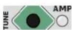
Press the module button AMP to access the parameters of the amplifier.
The display will show the selected module briefly:

Amplifier
In normal mode, the Level can be edited via the first encoder. To edit the Pan, alternate mode has to be enabled via the ALT button.
6.9.1 Level
Sets the overall volume. Use this parameter to match a preset against the others to prevent large jumps in volume when switching presets.
6.9.2 Pan
Sets the position of the sound in the stereo field.
6.10 Arpeggiator

The arpeggiator is a module that allows the creation of melodic patterns from chords or single notes.

Press the module button LFO to access the parameters of the arpeggiator. If you press the button more than once, the selection will cycle between LFO 1 and LFO 2. The arpeggiator's parameters are accessible in both cases.
In normal mode, the Mode and Grid parameters can be edited via the third and fourth encoder. To edit the Tempo and Hold parameters, alternate mode has to be enabled via the ALT button.
6.10.1 Mode
The mode parameter enables the arpeggiator and sets the order and the range of the generated notes.
The following table shows the possible modes as well as an example of generated notes when a C major chord (C3 |E3 |G3) is played.
| Off | C3 |E3 |G3 (no change) | |
| Up | C3 → E3 → G3 | |
| Down | G3 → E3 → C3 | |
| Random | (random order) | |
| Up 2 | C3 → C4 → E3 → E4 → G3 → G4 | |
| Down 2 | G3 → G4 → E3 → E4 → C3 → C4 | |
| Up 4 | C3 → C4 → C3 → C4 → E3 → E4 → E3 → E4 → G3 → G4 → G3 → G4 | |
| Down 4 | G3 → G4 → G3 → G4 → E3 → E4 → E3 → E4 → C3 → C4 → C4 → C3 → C4 |
6.10.2 Grid
This parameter determines the note value and the gate length of the generated notes.
The displayed value shows the number of clock ticks between each note. Because MIDI clock operates with a rate off 24ppq (pulses per quarter), a value of 24 refers to a quarter note.
The following table shows the relationship between the display and the note value:
| Display value | Note value |
| 48 1/2 | |
| 32 1/2 triplet | |
| 24 1/4 | |
| 16 1/4 triplet | |
| 12 1/8 | |
| 8 1/8 triplet | |
| 6 1/16 | |
| 3 1/32 | |
| 2 1/32 triplet | |
| 1 1/64 triplet |
The gate length of the notes is always equivalent to 50% of the note value.
Note: to modify the perceived gate length, make use of the envelope hold and decay parameters.
6.10.3 Tempo
There are two ways to set the base tempo for the arpeggiator:
- Free-running: the tempo is set manually, using this parameter.
- Synchronized: the tempo is set automatically, using MIDI clock (USB or DIN).
The Töörö automatically switches to synchronized mode if an external clock is received and reverts back to the free running mode when no other clock source is available.
The display always shows the last two digits of the BPM value. If the tempo is set above 100 BPM, a dot is shown after the first digit:

85 BPM

134 BPM
6.10.4 Hold
The hold function allows the arpeggiator to continue its sequence after all notes are released.
- When hold is disabled, notes are only generated when at least one note is pressed.
- With hold enabled, the arpeggiator starts when the first note is received. The generated sequence continues to play after all notes are released. It will then change as soon as a new note or chord is played.

No hold

Hold enabled
Note: in hold mode, the arpeggiator always stays in sync with the MIDI timing. New sequences of notes are only started on the grid. In normal mode, sequences starts immediately when notes are entered.
6.11 Modulation Matrix

The Töörö offers a modulation matrix with 8 sources. Each source can only modulate one destination. To assign the modulation sources to the different destinations, the matrix programming mode has to be entered.
6.11.1 Entering the Matrix Programming Mode
To enter matrix programming mode, press one of the Sources buttons on the right side of the panel. Use the ALT button before to access the secondary sources. The PGM LED will now be lit.
6.11.2 Programming a Modulation Assignment
These are the steps to program a modulation assignment:
- Enter the Matrix Programming Mode by pressing one of the sources buttons. Use the ALT button before if you want to use one of the alternate sources.
- The display will now indicate the selected modulation source.
- Select the module that should be modulated via the Module buttons.
- In order to program a modulation for a parameter that is accessible in alternate mode, make sure that the alternate mode is enabled via the ALT button.
- Turn the encoder that corresponds to the parameter that should be modulated.
At the end of this chapter, you'll find some examples how to program a modulation in detail.
6.11.3 Replacing a Modulation Assignment
Programming a new assignment on a modulation source will replace the previous one.
6.11.4 Clearing a Modulation Assignment
Hold down the EXIT and press one of the Sources buttons to clear any assignment for that modulation source.
6.11.5 Exiting the Matrix Programming Mode
The matrix programming mode can be exited at any time via the EXIT button. If no modulation assignment is edited for some seconds, the programming mode is also left automatically.
6.11.6 Modulation Sources
The following modulation sources can be used:

Env F (Filter envelope)

Env A (Amplifier envelope)

LFO 1

LFO 2
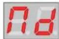
Mod wheel

Pitch (note number & pitch wheel)

Note velocity

Aftertouch
6.11.7 Modulation Destinations
The following parameters can be used as modulation destinations:
| Module Parameters |
| Oscillators Wave, Pitch, FM Amount, FM Rate, Sync, LevelExtra Noise, Ring ModulationFilter Cutoff, ResonanceShaper Cutoff, ResonanceLFO SpeedAmplifier Level, Pan |
6.11.8 Default Assignments
After initializing a preset, some mappings are pre-assigned with a modulation amount of 0. By sending the appropriate MIDI CCs, you can control the modulation amount for these default mappings.
| Source | Target |
| Env F | Osc 1 Sync |
| Env A | Osc 1 FM Amount |
| LFO 1 | Osc 1 Wave |
| LFO 2 | Ring Modulation |
| Mod wheel Filter Cutoff | |
| Pitch | Osc 2 Sync |
| Velocity | Osc 1 Wave |
| Aftertouch | LFO 1 Speed |
Furthermore, there is a default assignment for vibrato via mod wheel. Whenever the modulation amount of the mod wheel is set to 0 or modulation is disabled, a default modulation of LFO 2 to master pitch is applied and its intensity is controlled by the mod wheel.
6.11.9 Example 1: Applying LFO 1 Modulation on Osc 1 Pitch
- Make sure that the ALT LED is off. If not, press the ALT button to disable the alternate mode.
- Press the L1/VL button in the sources section.
- The display will now show L1 to indicate LFO 1 as modulation source.
- Press the OSC module button once or twice until the corresponding LED is lit in red and the display shows O1 briefly.
- Turn the second encoder to set the modulation amount for the Coarse parameter.
- Press the EXIT button in the sources section or wait a few seconds to exit the programming mode automatically.
6.11.10 Example 2: Applying Pitch Modulation on Amplifier Pan
- Make sure that the ALT LED is on. If not, press the ALT button to enable the alternate mode.
- Press the EA/PI button in the sources section.
- The display will now show PI to indicate pitch as modulation source.
- Press the AMP module button. The display will show AM briefly.
- Press the ALT button again to select the alternate parameters for modulation. The ALT LED will be lit now.
- Turn the first encoder to set the modulation amount for the Pan parameter.
- Press the EXIT button in the sources section or wait a few seconds to exit the programming mode automatically.
7 Multi Parameters
7.1 Overview
T"o"or"o overall multi structure

Note: The multi name is only accessible by Sysex messages.
7.2 Parts Mixer
The parts mixer allows to control the volume and balance of all parts. The four encoders correspond to the part number.
- Make sure that alternate mode is disabled to set the volumes or enable it to set the balances via the ALT button.
- Press and hold the VOL/BAL button.
- Turn the encoder that corresponds to the part to change the value.
- The LEDs above the encoders will show an optical representation of the value by their brightness and color.
7.3 Multi FX

The Töörö offers time-domain effects that are based on the repetition of the original signal at different intervals. The delay time of each effect can be modulated by an internal LFO. The effects are applied to all parts of the multi with the same intensity.

Press the module button AMP to access the parameters of the multi fx.
In normal mode, the Length, Feedback and Mix parameters can be edited via the second, third and fourth encoder. To edit the Mode, Speed and Depth parameters, alternate mode has to be enabled via the ALT button.
7.3.1 Length
Sets the delay time and therefore the frequency of the repetitions. The range of this parameter covers a span from a few milliseconds up to 780ms. Depending on the setting, you can get results in a wide range from thickening the sound with barely noticeable delays up to rhythmic patterns.
7.3.2 Feedback
The feedback parameter controls the amount of repetitions that are generated. When set to maximum, infinite repetitions are generated, allowing drones and lush ambient sounds.
7.3.3 Mix
This parameter sets the level of the effect signal that is mixed with the dry signal. The level of the dry signal is not affected by this setting.
7.3.4 Mode
This parameter chooses which effect is being used:

No effect

Mono delay
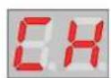
Chorus / Flanger

Stereo delay
- The mono delay repeats the original signal a defined number of times. The repetitions are progressively degraded, they lose their loudness, dynamic precision and some of their frequency content.
- Although the chorus/flanger effect does not feel like a delay, it uses the same ground principles. The repetitions are closer and modulated, the perceived effect is a constant variation of the sound spectrum giving it a thicker character. This effect has multiple uses, try to experiment with different settings!
- The stereo delay is very similar to the mono delay. The essential difference is the repetitions come first from the left channel and then from the right channel and so on. It gives a nice stereo image to the sound.
7.3.5 Speed
Sets the speed of the modulation that is applied to the delay time. It covers a range from 16s to 6Hz.
7.3.6 Depth
Sets the amount of modulation that is applied to the delay time.
8 Filter Tuning
The Töörö contains an analog FL A847 filter for each voice. According to the nature of analog components, each voice will have slightly different sound. In order to minimize these variations, the filter can be tuned via an automated procedure.
- Wait at least 15 minutes after the Töörö has been powered up. This is to ensure that all internal components are working at their desired operation temperature.
- Turn down the volume on your attached audio system or disconnect the output jacks. While the tune procedure is running, some high pitched tones will be generated at high output levels that could damage your speakers and hearing.
- Press and hold the SYSTEM button. Then press the module button labelled AMP. This button also has a secondary vertical label TUNE left to it.
- The tune procedure is now started and will take about 2 minutes to proceed. While running, the display will show some screens that represent the individual steps.
- After the tuning is done, the display will return to show the preset number again.
9 Firmware Update
To benefit from new features (and potential bug-fixes), the internal firmware of the Töörö can be re-programmed. Updates should only be performed when absolutely necessary and the procedure steps and recommendations should be strictly followed.
In order to check which version of the firmware is currently installed, the display will show the version number briefly right after the Töörö is powered on.
Important: Failing to observe the update procedure may simply brick your device! Therefore, please proceed carefully.
To update your Töörö instrument to the latest firmware revision, please refer to the appropriate update documentation and read the following tutorials at:
https://fredslab.net/en/tooro-module.php
10 Restoring the Factory Presets
To restore the factory presets, maintain the PRESET button pressed at startup until the display shows FS for "Factory Setting".
Remark: The first 40 presets slots will be overwritten. Make sure to backup the previous content if needed.
11 Specifications
Here you will find all technical data concerning the T“o”or“o.
11.1 Sound Engine
11.1.1 General
• Number of parts: 4
• Maximal polyphony: 6 voices
- MIDI channel selection, overall volume and panning settings per part
11.1.2 Oscillators
Two 12bit digital oscillators with:
- Waveform morphing
• Factory and user tables
• Additional sine modulator for linear through zero phase modulation
• Auto-sync feature (hardsync)
Additional sources:
- White noise
- Ring modulation of both oscillators
11.1.3 Filter
FL A847 optocoupler based 12dB/octave low-pass filter with self-oscillation and saturation.
11.1.4 Shaper
Digital multimode filter with low-pass, band-pass and high-pass.
11.1.5 Envelopes
Two ADSR envelopes with additional hold stage and multiple triggering options.
11.1.6 LFOs
Two complex LFOs with various waveforms and AD envelope.
11.1.7 Arpeggiator
MIDI-syncable arpeggiator with multiple modes and patterns.
11.1.8 DCA
Digitally controlled attenuator with volume and panning control.
11.1.9 Multi FX
Effect types:
• Mono modulated delay
- Stereo chorus / flanger
- Stereo modulated line
11.2 Memory
- 100 user presets
- 10 user multis
11.3 Line Outputs
- -10dBu (single voice) / 0.25 VRMS / 0.7Vpkpk
• +20dBu (full scale) / 7.7V RMS / 20Vpkpk - Impedance DC 1kΩ, AC 0Ω (f < 30kHz)
11.4 Audio Resolution
- 44kHz, 12Bit
11.5 Master Clocks
- MCU: 80MHz
- USB: 48MHz
- OSCs: 792kHz
11.6 Power
• USB bus power +5V +/-5%
- 350mA (maximum)
11.7 Connectors
• 2 line-level unbalanced 6.35mm jacks (mix left & right)
- 2 instrument-level 3.5mm jacks for separate voice outputs (for voice 1-4 only)
• 1 MIDI in DIN jack
• 1 MIDI out DIN jack
• 1 USB type B socket (for power and MIDI over USB)
11.8 User Interface
- 4 encoders
• 14 tactile switches
• Dual digit 7-segment hexadecimal display
• 12 leds - 1 power switch
11.9 Dimensions & Weight
- 160mm x 100mm x 60mm (unit)
• 350 grams (unit)
11.10 Mechanics
• Aluminum industrial enclosure
- 4 rubber feet
11.11 Accessories
- Quickstart guide
- USB cable 1m
12 MIDI Implementation
12.1 Channel Voice Messages
Channel Voice Messages are used to send basic music events to one specific channel or part. They consists in 3 bytes: the status byte, followed by two data bytes. Here follows the list of supported messages.
12.1.1 Note Off
Stops the playback of a note.
Byte:012
Data:0x8cnotevelo
c =MIDIchannel(0-15)
note=MIDInote(0-127)
velo=notevelocity(0-127)
12.1.2 Note On
Starts the playback of a note.
Byte:012
Data:0x9cnotevelo
    c =MIDIchannel(0-15)
    note=MIDInote(0-127)
    velo=notevelocity(1-127)*
*Note:avelocityof0correspondstoaNoteoffevent.
12.1.3 Polyphonic Aftertouch
Polyphonic aftertouch / pressure
Byte:01 2
Data:0xAcnotevalue
    c =MIDIchannel(0-15)
    note =MIDInote
    value=aftertouchvalue
12.1.4 Controller Change
Modifies a specific sound parameter value of the given channel (= part).
Byte:01 2
Data:0xBcindexvalue
    c =MIDIchannel(0-15)
    index=controllernumber(seetheCList)
    value=controllervalue*(seetheCList)
*Note: internalparametervaluesarerepresentedin10bitformat.
SinceMIDICCscanonlytransmit7bitvalues, valuestransmitted areinternallyinterpolatedandsmoothed.
12.1.5 Program Change
Selects the current preset.
Byte:01
Data:0xCcpreset
c=MIDIchannel(0-15)
preset=presetnumber(0-99)
12.1.6 Channel Aftertouch
Controls the pressure level of the given channel (= part) notes.
Byte:012
Data:0xDcvalue
c=MIDIchannel(0-15)
value=Pressurevalue(0-127)
12.1.7 Pitch Bend
Increases or decreases the pitch of the given channel (= part) notes.
Byte:012
Data:0xEcleastmost
c=MIDIchannel(0-15)
least=leastsignificant7bitof14bitbendvalue*
most=mostsignificant7bitof14bitbendvalue*
*Note:bendvalueiscenteredaround0x4000=0cents.
12.2 System Real Time Messages
System Real Time Messages are used to send high-priority messages relative to music timing and sequences.
12.2.1 Clock Start
Start all parts arpeggiators if enabled.
Byte:0
Data:0xFA
12.2.2 Clock Continue
Re-start all parts arpeggiators if enabled.
Byte:0
Data:0xFB
12.2.3 Clock Stop
Stop all parts arpeggiator.
Byte:0
Data:0xFC
12.2.4 Clock Tick
Synchronizes the MIDI master clock of the sound module. A tick corresponds to 1/24th of a quarter note.
Byte:0
Data:0xF8
12.2.5 Active Sensing
Ensure the MIDI connection is working.
Once first sent, active sensing messages must be sent to the module periodically. If the module stops receiving active sensing messages for an extended period of time, it will automatically perform a all sounds off.
Byte:0
Data:0xFE
12.3 MIDI CC Assignments
Controller Change Messages are used to alter sound parameters of a given channel. They allow more musical expressivity by adjusting the sound character while playing or allow the editing of the part parameters from an extended/remote MIDI interface or a computer software (sequencer or preset editor).
The messages consist of 3 bytes: the status byte, followed by the control number byte and then terminated by the control value byte. Here's the list of supported messages:
| Section Parameter CC Number | ||
| General Modwheel 1 | ||
| Preset Osc 1 Wave | 70 | |
| Osc 1 Coarse | 21 | |
| Osc 1 FM Amount | 22 | |
| Osc 1 Level | 23 | |
| Osc 1 Table | 24 | |
| Osc 1 Fine | 25 | |
| Osc 1 FM Rate | 26 | |
| Osc 1 Sync | 27 | |
| Osc 2 Wave | 77 | |
| Osc 2 Coarse | 31 | |
| Osc 2 FM Amount | 32 | |
| Osc 2 Level | 33 | |
| Osc 2 Table | 34 | |
| Osc 2 Fine | 35 | |
| Osc 2 FM Rate | 36 | |
| Osc 2 Sync | 37 | |
| Extra Noise | 78 | |
| Extra Ring | 79 | |
| Env A Attack | 73 | |
| Env A Decay | 40 | |
| Env A Sustain | 41 | |
| Env A Release | 72 | |
| Env A Velo | 43 | |
| Env A Hold | 42 | |
| Env A After | 44 | |
| Env A Trigger | 45 | |
| Env F Attack | 46 | |
| Env F Decay | 47 | |
| Env F Sustain | 48 | |
| Env F Release | 49 | |
| Env F Velo | 51 | |
| Env F Hold | 50 | |
| Env F After | 52 | |
| Env F Trigger | 53 | |
| Preset Filter Resonance 71 | ||
| Filter Cutoff 74 | ||
| Filter Env F Amount 54 | ||
| Filter Track 55 | ||
| Filter After 56 | ||
| Filter LFO 1 Amount 57 | ||
| Shaper Cutoff | ||
| Shaper Resonance | ||
| Shaper Env A Amount | ||
| Shaper Track | ||
| Shaper Mode | ||
| Shaper LFO 2 Amount | ||
| LFO 1 Shape | ||
| LFO 1 Speed | ||
| LFO 1 Rise 104 | ||
| LFO 1 Phase | ||
| LFO 2 Shape | ||
| LFO 2 Speed | ||
| LFO 2 Rise 108 | ||
| LFO 2 Phase | ||
| Arp Mode | ||
| Arp Grid | ||
| Arp Tempo 112 | ||
| Arp Hold | ||
| Amp Level 80 | ||
| Amp Pan | ||
| Modulation Env F | ||
| Modulation Env A | ||
| Modulation LFO 1 | ||
| Modulation LFO 2 | ||
| Modulation Mod Wheel | ||
| Modulation Pitch | ||
| Modulation Velocity | ||
| Modulation Aftertouch | ||
| Bend Range | ||
| Tune | ||
| Multi | Level | 07 |
| Balance | 10 | |
| FX Mix | 91 | |
| FX Feedback | 12 | |
| FX Length | 14 | |
| FX Depth | 93 | |
| FX Mode | 13 | |
| FX Speed | 15 | |
| System | All Sounds Off | 120 |
| Reset All Controllers | 121 | |
| All Notes Off | 123 | |
| Omni Off | 124 | |
| Omni On | 125 | |
| Mono Mode 126 | ||
| Poly Mode | 127 | |
13 Sysex Implementation
Sysex or System Exclusive Messages are lengthier MIDI messages used to transfer, save and load preset and multi parameters. Two types of messages exist: requests and dumps.
Requests are sent to the music instrument to ask for the dump of a specific preset or multi.
Dumps are sent by the instrument in response to the reciprocal request or are sent to the instrument to replace a specific preset or multi. Dumps previously requested can be sent back without any alteration, to restore a previous memory configuration.
13.1 Requests
13.1.1 Multi Request
Request a specific multi from the memory.
Byte:0 1 2 3
Data:0xF00x010xMI0xF7
0xF0=Sysexstart
0x01=Service1=>"Multirequest"
0xMI=Multiid(0-9=memoryslot,0x7F=multieditbuffer)
0xF7=Sysexend
13.1.2 Preset Request
Request a specific preset from the memory.
Byte:0 1 2 3
Data:0xF00x020xPI0xF7
0xF0=Sysexstart
0x02=Service2=>"Presetrequest"
0xPI=Presetid(0-99=memoryslot,0x70-0x73=Part1-4)
0xF7=Sysexend
13.1.3 Preset Parameter Request
Request a specific preset parameter from the memory.
Byte: 0 1 2 3 4 5
Data: 0xF00x030xPI0xIDL0xIDH0xF7
    0xF0 =Sysexstart
    0x03 =Service3=>"Presetparameterrequest"
    0xPI =Presetid(0x70-0x73=Part1-4)
    0xIDL=Parameterid(lower7bits)
    0xIDH=Parameterid(higher7bits)
    0xF7 =Sysexend
See Preset Dump parameters table for IDs.
13.1.4 Multi Parameter Request
Request a specific multi parameter from the memory.
Byte:012345
Data:0xF00x040x000xIDL0xIDH0xF7
0xF0=Sysexstart
0x04=Service4=>"Multiparameterrequest"
0x00=Reserved,setto0
0xIDL=Parameterid(lower7bits)
0xIDH=Parameterid(higher7bits)
0xF7=Sysexend
See Multi Dump parameters table for IDs.
13.2 Dumps
13.2.1 Multi Dump
Multi dump. Sysex is 104 bytes long.
Byte:012n103
Data:0xF00x110xMI...0xF7
0xF0=Sysexstart
0x11=Service17=>"Multidump"
0xMI=Multiid(0-10=memoryslot,0x7F=currenteditbuffer)
...data(100bytes)
0xF7=Sysexend
Data is packed, see Data Packing section for details.
| ID | Index | Length | Description |
| 0 | 0 | 2 Preset | ID Part 1 |
| 1 | 2 | 2 Preset | ID Part 2 |
| 2 | 4 | 2 Preset | ID Part 3 |
| 3 | 6 | 2 Preset | ID Part 4 |
| 4 | 8 | 2 MIDI | Channel Part 1 |
| 5 | 10 | 2 MIDI Channel Part 2 | |
| 6 | 12 | 2 MIDI Channel Part 3 | |
| 7 | 14 | 2 MIDI Channel Part 4 | |
| 8 | 16 | 2 Volume Part 1 | |
| 9 | 18 | 2 Volume Part 2 | |
| 10 | 20 | 2 Volume Part 3 | |
| 11 | 22 | 2 Volume Part 4 | |
| 12 | 24 | 2 Balance Part 1 | |
| 13 | 26 | 2 Balance Part 2 | |
| 14 | 28 | 2 Balance Part 3 | |
| 15 | 30 | 2 Balance Part 4 | |
| 16 | 32 | 2 FX Length | |
| 17 | 34 | 2 FX Feedback | |
| 18 | 36 | 2 FX Mix | |
| 19 | 38 | 2 FX Mode | |
| 20 | 40 | 2 FX Speed | |
| 21 | 42 | 2 FX Depth | |
| 22 | 44 | 2 Reserved | |
| 23 | 46 | 2 Flags (internal) | |
| 24 | 48 | 32 Name |
13.2.2 Preset Dump
Preset dump. Sysex is 264 bytes long.
Byte:012n263
Data:0xF00x120xPI...0xF7
0xF0=Sysexstart
0x12=Service18=>"Presetdump"
0xPI=Presetid(0-99=memoryslot,0x70-0x73=Part1-4)
...data(260bytes)
0xF7=Sysexend
Data is packed, see Data Packing section for details.
| ID | Index | Length | Description |
| 0 | 0 2 Osc 1 | Wave | |
| 1 | 2 2 Osc 1 | Coarse | |
| 2 | 4 2 Osc 1 | FM Amount | |
| 3 | 6 2 Osc 1 | Level | |
| 4 | 8 2 Osc 1 | Table | |
| 5 | 10 2 Osc 1 | Fine | |
| 6 | 12 2 Osc 1 | FM Rate | |
| 7 | 14 2 Osc 1 | Sync | |
| 8 | 16 2 Osc 2 | Wave | |
| 9 | 18 2 Osc 2 | Coarse | |
| 10 | 20 2 Osc 2 | FM Amount | |
| 11 | 22 2 Osc 2 | Level | |
| 12 | 24 2 Osc 2 | Table | |
| 13 | 26 2 Osc 2 | Fine | |
| 14 | 28 2 Osc 2 | FM Rate | |
| 15 | 30 2 Osc 2 | Sync | |
| 16 | 32 2 Extra | Noise | |
| 17 | 34 2 Extra | Ring | |
| 18 | 36 2 Shaper | Cutoff | |
| 19 | 38 2 Shaper | Resonance | |
| 20 | 40 2 Shaper | Env A Amount | |
| 21 | 42 2 Shaper | Track | |
| 22 | 44 2 Shaper | Mode | |
| 23 | 46 2 Shaper | LFO 2 Amount | |
| 24 | 48 2 Filter | Cutoff | |
| 25 | 50 2 Filter | Resonance | |
| 26 | 52 2 Filter | Env F Amount | |
| 27 | 54 2 Filter | Track | |
| 28 | 56 2 Filter | After | |
| 29 | 58 2 Filter | LFO 1 Amount | |
| 30 | 60 2 Env F | Attack | |
| 31 | 62 2 Env F | Decay | |
| 32 | 64 2 Env F | Sustain | |
| 33 | 66 2 Env F | Release | |
| 34 | 68 2 Env F | Velo | |
| 35 | 70 2 Env F | Hold | |
| 36 | 72 2 Env F | After | |
| 37 | 74 2 Env F | Trigger | |
| 38 | 76 2 Env A | Attack | |
| 39 | 78 2 Env A | Decay | |
| 40 | 80 2 Env A | Sustain | |
| 41 | 82 2 Env A | Release | |
| 42 | 84 2 Env A | Velo | |
| 43 | 86 2 Env A | Hold | |
| 44 | 88 2 Env A | After | |
| 45 | 90 2 Env A | Trigger |
| ID | Index | Length | Description |
| 46 | 92 | 2 LFO | 1 Shape |
| 47 | 94 | 2 LFO | 1 Speed |
| 48 | 96 | 2 LFO | 1 Rise |
| 49 | 98 | 2 LFO | 1 Phase |
| 50 | 100 | 2 LFO | 2 Shape |
| 51 | 102 | 2 LFO | 2 Speed |
| 52 | 104 | 2 LFO | 2 Rise |
| 53 | 106 | 2 LFO | 2 Phase |
| 54 | 108 | 2 Arp | Mode |
| 55 | 110 | 2 Arp | Grid |
| 56 | 112 | 2 Arp | Tempo |
| 57 | 114 | 2 Arp | Hold |
| 58 | 116 | 2 Amp | Level |
| 59 | 118 | 2 Amp | Pan |
| 60 | 120 | 2 Env | F Amount |
| 61 | 122 | 2 Env | F Target |
| 62 | 124 | 2 Env | A Amount |
| 63 | 126 | 2 Env | A Target |
| 64 | 128 | 2 LFO | 1 Amount |
| 65 | 130 | 2 LFO | 1 Target |
| 66 | 132 | 2 LFO | 2 Amount |
| 67 | 134 | 2 LFO | 2 Target |
| 68 | 136 | 2 Wheel | Amount |
| 69 | 138 | 2 Wheel | Target |
| 70 | 140 | 2 Pitch | Amount |
| 71 | 142 | 2 Pitch | Target |
| 72 | 144 | 2 Velo | Amount |
| 73 | 146 | 2 Velo | Target |
| 74 | 148 | 2 After | Amount |
| 75 | 150 | 2 After | Target |
| 76-79 | 152 | 8 Osc | 1 Waves |
| 80-83 | 160 | 8 Osc | 2 Waves |
| 84 | 168 | 2 Tune | |
| 85 | 170 | 2 Reserved | |
| 86 | 172 | 2 Bend | Range |
| 87 | 174 | 2 Flags (internal) | |
| 88 | 176 | 32 Name |
13.2.3 Preset Parameter Dump
Preset parameter dump. Sysex is 8 bytes long.
Byte:01234567
Data: 0xF00x130xPI0xIDLOxIDH0xVLL0xVLH0xF7
0xF0=Sysexstart
0x13=Service19=>"Presetparameterdump"
0xPI=Presetid(0x70-0x73=Part1-4)
0xIDL=Parameterid(lower7bits)
0xIDH=Parameterid(higher7bits)
0xVLL=Parametervalue(lower7bits)
0xVLH=Parametervalue(higher7bits)
0xF7=Sysexend
See Preset Dump parameters table for IDs.
13.2.4 Multi Parameter Dump
Multi parameter dump. Sysex is 8 bytes long.
Byte:01234567
Data:0xF00x140x000xIDLOxIDH0xVLL0xVLH0xF7
0xF0=Sysexstart
0x14=Service20=>"Multiparameterdump"
0x00=Reserved,setto0
0xIDL=Parameterid(lower7bits)
0xIDH=Parameterid(higher7bits)
0xVLL=Parametervalue(lower7bits)
0xVLH=Parametervalue(higher7bits)
0xF7=Sysexend
See Multi Dump parameters table for IDs.
13.2.5 Data Packing
Sysex payload data is packed because of the 7-bit restriction of the MIDI format.
ByteDescription
0:byte0, lowest7bits
1:byte1, lowest7bits
2:byte2, lowest7bits
3:byte3, lowest7bits
4:tops, top7thbitsofthe4precedingbytes
5:byte4, lowest7bits
6:byte5, lowest7bits
7:byte6, lowest7bits
8:byte7, lowest7bits
9:tops, top7thbitsofthe4precedingbytes
...
Packing algorithm:
intlength=3;
intsize=sizeof(content);
for(inti=0;i<size/4;i++){
    inttops=0;
    sysex[length++]=*data&0x7F;
    tops|=(*data++&0x80)>>7;
    sysex[length++]=*data&0x7F;
    tops|=(*data++&0x80)>>6;
    sysex[length++]=*data&0x7F;
    tops|=(*data++&0x80)>>5;
    sysex[length++]=*data&0x7F;
    tops|=(*data++&0x80)>>4;
    sysex[length++]=top;
14 Schematics
To minimize electronic waste and ensure long product life, Fred's Lab is willing to provide all technical documents needed to repair his products. The following schematics are provided "as is" with no warranty of any kind. Any modification made to a Fred's Lab instrument immediately voids the included 3-year product warranty. Repairs must be carried out by a competent repair service. Fred's Lab stays available for the maintenance of your instruments. Do not hesitate to contact the support service for a free quote. Spare parts can directly be ordered from us.
Intellectual property:
The following technical documents are provided for advisory, repair and educational purposes only. They remain the entire property of Fred's Lab and cannot be reproduced without a written authorization. Users are granted to draw inspiration from this information for their projects (commercial or not), while respecting the limits of non-cloning or counterfeiting the original product. If in doubt about legal matters, please contact us.


Schematics and tech docs
Copyright Fred's Lab - All rights reserved 2010, 2021 / Rasp Germany
2019 - 2021 / Bonn Germany Schematics are provided for m
CE DECLARATION OF CONFORMITY
- Product unique identification:
T“o”or“o analog and digital sound module
Belonging to the category "multimedia electronic equipment"
- Address of the manufacturer and his authorized representative:
Fr'ed'eric Meslin Audioger"ate
Herwarthstraße, 20
53115 Bonn, Germany
Email: fred@fredslab.net
Telephone: +49 228 53451657 (office hours)
- Object of the declaration:
This equipment conforms to the following requirements:
• EN 55032:2015 (emission), EN 55035:2017 (immunity)
• EN 61000-4-2:2009 (ESD)
• EN 61000-4-3:2006 + A1:2008 + A2:2010 (immunity)
• EN 61000-4-8:2010 (immunity)
• EN 61000-6-3 (interference)
• 2011/65/EU (ROHS 2), 2012/19/EU (WEEE)
After examinations conducted by the independent laboratory:
Report: EMC Testreport 1290 / 2020 (22 July 2020)
- Signed for and on behalf of Fr'ed'eric Meslin Audioger"ate:
Fr'ed'eric Meslin, Lead Engineer of Fred's Lab
Bonn, the 22/07/2020
15.2 Canada: Interference Regulation
This device does not exceed the Class B limits for radio noise emissions from digital apparatus set out in the radio interference regulation of the Canadian Department of Communications.
This equipment has been verified to comply with the limits for a class B computing device, pursuant to FCC Rules. In order to maintain compliance with FCC regulations, shielded cables must be used with this equipment. Operation with non-approved equipment or unshielded cables is likely to result in interference to radio and TV reception.
Important: Changes and modifications made to the equipment without the approval of the manufacturer can void your authority to operate this equipment.
Note: This equipment has been tested and found to comply with the limits for a Class B digital device, pursuant to part 15 of the FCC Rules. These limits are designed to provide reasonable protection against harmful interference in a residential installation. This equipment generates, uses and can radiate radio frequency energy and, if not installed and used in accordance with the instructions, may cause harmful interference to radio communications.
However, there is no guarantee that interference will not occur in a particular installation. If this equipment does cause harmful interference to radio or television reception, which can be determined by turning the equipment off and on, the user is encouraged to try to correct the interference by one or more of the following measures:
• Reorient or relocate the receiving antenna
- Increase the separation between the equipment and receiver
- Connect the equipment into an outlet on a circuit different from that to which the receiver is connected
- Consult the dealer or an experienced radio/TV technician for help
- TÖÖRÖ MODULE USER AND SERVICE MANUAL
- INTRODUCTION
- LEGAL NOTICES
- SUPPORT REQUESTS
- COPYRIGHT INFORMATION
- WARRANTY
- SPECIAL THANKS
- PRECAUTIONS
- CONTENTS
- 1 PRESENTATION 9
- 2 REQUIREMENTS 9
- 3 INSTRUMENT SETUP 11
- 4 INSTRUMENT OPERATION 12
- 5 PRESET & MULTI MANAGEMENT 15
- 6 PRESET PARAMETERS 19
- 7 MULTI PARAMETERS 38
- 8 FILTER TUNING 41
- 9 FIRMWARE UPDATE 41
- 10 RESTORING THE FACTORY PRESETS 41
- 11 SPECIFICATIONS 42
- 12 MIDI IMPLEMENTATION 45
- 13 SYSEX IMPLEMENTATION 50
- 14 SCHEMATICS 58
- 15 NORMS 68
- 1 PRESENTATION
- 1.1 WHAT IS MIDI
- 1.2 REMARKS ON POLYPHONY
- 2 REQUIREMENTS
- 2.1 AN AUDIO SYSTEM
- 2.2 A MIDI CONTROLLER
- 2.3 A USB POWER SOURCE
- 2.4 REMARKS ON USB NOISE
- SOLUTION 1
- SOLUTION 2
- 3 INSTRUMENT SETUP
- STEP 1: AUDIO
- STEP 2: MIDI
- STEP 3: POWER
- STEP 4: AUDIO SYSTEM
- 4 INSTRUMENT OPERATION
- 4.1 CONNECTORS
- A USB - 5V
- B MIDI IN
- ©MIDI OUT
- D VOICES 1&2 / 3&4
- E F LEFT & RIGHT
- 4.2 CONTROLS & INDICATORS
- ①POWER SWITCH
- ② MODULE BUTTONS & LEDS
- ③ SYSTEM BUTTON
- ④ALT BUTTON & LED
- ⑤VOL/BAL BUTTON
- ⑥ POLY LED
- ⑦ PARAMETER ENCODERS & LEDS
- ⑧PGM LED
- ⑨ EXIT BUTTON
- 10 SOURCES BUTTONS
- ⑪ PRESET/MULTI BUTTON
- 127-SEGMENT DISPLAY
- 4.3 EDITING PARAMETERS
- 4.3.1 PARAMETER LEDS
- 4.3.2 PARAMETER DISPLAY
- 5 PRESET & MULTI MANAGEMENT
- 5.1 SELECTING A PART
- 5.2 SETTING THE MIDI CHANNEL
- 5.3 SELECTING A PRESET
- 5.4 SAVING A PRESET
- 5.4.1 OVERWRITING THE CURRENT PRESET
- 5.4.2 SAVING A PRESET TO A DIFFERENT MEMORY LOCATION
- 5.5 COPYING PRESETS
- 5.6 INITIALIZING A PRESET
- 5.7 DUMPING A PRESET VIA SYSEX
- 5.8 SELECTING A MULTI
- 5.9 SAVING A MULTI
- 5.9.1 OVERWRITING THE CURRENT MULTI
- 5.9.2 SAVING A MULTI TO A DIFFERENT MEMORY LOCATION
- 5.10 COPYING MULTIS
- 5.11 INITIALIZING A MULTI
- 5.12 DUMPING A MULTI VIA SYSEX
- 6 PRESET PARAMETERS
- 6.1 OVERVIEW
- T“O”OR“O OVERALL PRESET STRUCTURE
- NOTES
- 6.2 VOICE MODE
- 6.3 OSCILLATORS
- 6.3.1 WAVE
- 6.3.2 TABLE
- 6.3.3 COARSE TUNE
- 6.3.4 FINE TUNE
- 6.3.5 FM AMOUNT
- 6.3.6 FM RATE
- 6.3.7 LEVEL
- 6.3.8 SYNC
- 6.4 EXTRA
- 6.4.1 NOISE LEVEL
- 6.4.2 RINGMODULATOR LEVEL
- 6.5 FILTER
- 6.5.1 CUTOFF
- 6.5.2 RESONANCE
- 6.5.3 ENV F AMOUNT
- 6.5.4 LFO 1 AMOUNT
- 6.5.5 PITCH TRACKING
- 6.5.6 AFTERTOUCH AMOUNT
- 6.6 SHAPER
- 6.6.1 CUTOFF FREQUENCY
- 6.6.2 RESONANCE
- 6.6.3 ENV A AMOUNT
- 6.6.4 LFO 2 AMOUNT
- 6.6.5 PITCH TRACKING
- 6.6.6 MODE
- 6.7 LFOS
- 6.7.1 SHAPE
- 6.7.2 SPEED
- 6.7.3 RISE
- 6.7.4 PHASE
- 6.8 ENVELOPES
- 6.8.1 ATTACK TIME
- 6.8.2 DECAY TIME
- 6.8.3 SUSTAIN LEVEL
- 6.8.4 RELEASE TIME
- 6.8.5 VELOCITY AMOUNT
- 6.8.6 HOLD TIME
- 6.8.7 AFTERTOUCH AMOUNT
- 6.8.8 TRIGGER MODE
- 6.9 AMPLIFIER
- 6.9.1 LEVEL
- 6.9.2 PAN
- 6.10 ARPEGGIATOR
- 6.10.1 MODE
- 6.10.2 GRID
- 6.10.3 TEMPO
- 6.10.4 HOLD
- 6.11 MODULATION MATRIX
- 6.11.1 ENTERING THE MATRIX PROGRAMMING MODE
- 6.11.2 PROGRAMMING A MODULATION ASSIGNMENT
- 6.11.3 REPLACING A MODULATION ASSIGNMENT
- 6.11.4 CLEARING A MODULATION ASSIGNMENT
- 6.11.5 EXITING THE MATRIX PROGRAMMING MODE
- 6.11.6 MODULATION SOURCES
- 6.11.7 MODULATION DESTINATIONS
- 6.11.8 DEFAULT ASSIGNMENTS
- 6.11.9 EXAMPLE 1: APPLYING LFO 1 MODULATION ON OSC 1 PITCH
- 6.11.10 EXAMPLE 2: APPLYING PITCH MODULATION ON AMPLIFIER PAN
- 7 MULTI PARAMETERS
- 7.1 OVERVIEW
- 7.2 PARTS MIXER
- 7.3 MULTI FX
- 7.3.1 LENGTH
- 7.3.2 FEEDBACK
- 7.3.3 MIX
- 7.3.4 MODE
- 7.3.5 SPEED
- 7.3.6 DEPTH
- 8 FILTER TUNING
- 9 FIRMWARE UPDATE
- 10 RESTORING THE FACTORY PRESETS
- 11 SPECIFICATIONS
- 11.1 SOUND ENGINE
- 11.1.1 GENERAL
- 11.1.2 OSCILLATORS
- 11.1.3 FILTER
- 11.1.4 SHAPER
- 11.1.5 ENVELOPES
- 11.1.6 LFOS
- 11.1.7 ARPEGGIATOR
- 11.1.8 DCA
- 11.1.9 MULTI FX
- 11.2 MEMORY
- 11.3 LINE OUTPUTS
- 11.4 AUDIO RESOLUTION
- 11.5 MASTER CLOCKS
- 11.6 POWER
- 11.7 CONNECTORS
- 11.8 USER INTERFACE
- 11.9 DIMENSIONS & WEIGHT
- 11.10 MECHANICS
- 11.11 ACCESSORIES
- 12 MIDI IMPLEMENTATION
- 12.1 CHANNEL VOICE MESSAGES
- 12.1.1 NOTE OFF
- 12.1.2 NOTE ON
- 12.1.3 POLYPHONIC AFTERTOUCH
- 12.1.4 CONTROLLER CHANGE
- 12.1.5 PROGRAM CHANGE
- 12.1.6 CHANNEL AFTERTOUCH
- 12.1.7 PITCH BEND
- 12.2 SYSTEM REAL TIME MESSAGES
- 12.2.1 CLOCK START
- 12.2.2 CLOCK CONTINUE
- 12.2.3 CLOCK STOP
- 12.2.4 CLOCK TICK
- 12.2.5 ACTIVE SENSING
- 12.3 MIDI CC ASSIGNMENTS
- 13 SYSEX IMPLEMENTATION
- 13.1 REQUESTS
- 13.1.1 MULTI REQUEST
- 13.1.2 PRESET REQUEST
- 13.1.3 PRESET PARAMETER REQUEST
- 13.1.4 MULTI PARAMETER REQUEST
- 13.2 DUMPS
- 13.2.1 MULTI DUMP
- 13.2.2 PRESET DUMP
- 13.2.3 PRESET PARAMETER DUMP
- 13.2.4 MULTI PARAMETER DUMP
- 13.2.5 DATA PACKING
- 14 SCHEMATICS
- INTELLECTUAL PROPERTY
- CE DECLARATION OF CONFORMITY
- FR'ED'ERIC MESLIN AUDIOGER"ATE
- 15.2 CANADA: INTERFERENCE REGULATION
Brand : Fred's Lab
Model : Töörö
Category : Synthesizer