DCP 100 - Uncategorized QSC - Free user manual and instructions
Find the device manual for free DCP 100 QSC in PDF.


| Type | Digital Cinema Processor |
| Model | DCP 100 |
| Dimensions (H x W x D) | 5.25 x 19 x 15 inches (133 x 483 x 381 mm) |
| Power Supply | 100–240 VAC, 50/60 Hz |
| Digital Audio Inputs | 10 channels AES3 (DB-25: pairs 1-4, plus HI/VI pair 8) |
| Analog Audio Inputs | Main 8-channel DB-25, Mic/Line XLR (with phantom power), stereo RCA line inputs |
| Digital Audio Outputs | Up to 8 DataPorts for QSC amplifiers (HD-15) |
| Audio Performance (Analog Input) | Dynamic range >105 dB, THD+N <0.005% |
| A/D Conversion | 24-bit delta-sigma, 48 kHz |
| D/A Conversion | 24-bit delta-sigma, 48 kHz |
| DSP Processing | 24-bit IIR filters, crossover (Linkwitz-Riley/Butterworth up to 48 dB/octave), parametric EQ, 28-band graphic EQ, delay, polarity |
| Front Panel Display | 4.3-inch 16:9 color TFT touch screen (480 x 272) |
| Monitor Speaker | 4-inch full-range, 10 W Class D amplifier |
| Network Interfaces | QSControl (10/100 Ethernet), RS-232 serial, USB Type B (configuration) |
| Configuration Storage | SD memory card (2 GB included) for backup and quick replacement |
| Special Outputs | Hearing Impaired (HI) and Visually Impaired (VI) mixes, monitor output, relay outputs (2), logic outputs (2) |
| Automation Inputs | 6 digitally sampled analog inputs (contact closure or 10k pot) |
| Operating Temperature | Up to 50°C (122°F) |
| Safety Certifications | FCC Class B (USA), CE, RoHS compliant, China RoHS table |
| Warranty | 3 years limited (USA; other countries vary) |
Frequently Asked Questions - DCP 100 QSC
User questions about DCP 100 QSC
0 question about this device. Answer the ones you know or ask your own.
Ask a new question about this device
Download the instructions for your Uncategorized in PDF format for free! Find your manual DCP 100 - QSC and take your electronic device back in hand. On this page are published all the documents necessary for the use of your device. DCP 100 by QSC.
USER MANUAL DCP 100 QSC
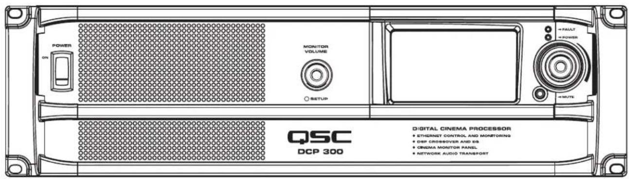
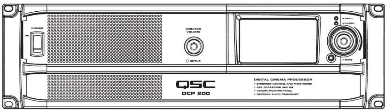
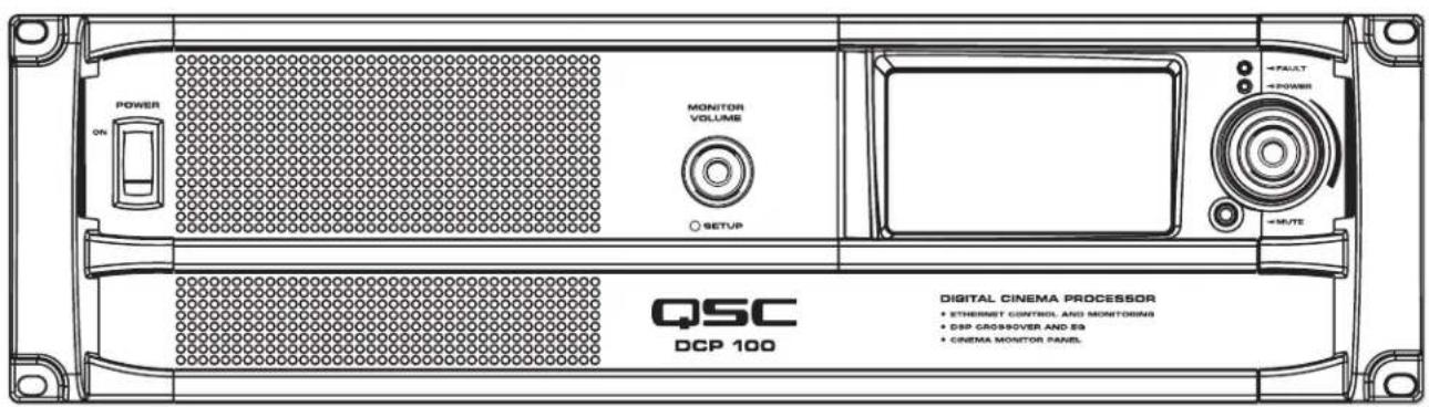
DCP – Digital Cinema Processor
TD-000285-00 C
*TD-000285-00*
IMPORTANT SAFETY PRECAUTIONS AND EXPLANATION OF SYMBOLS

WARNING!


The lightning flash with arrowhead symbol within an equilateral triangle is intended to alert the user to the presence of uninsulated "dangerous" voltage within the product's enclosure that may be of sufficient magnitude to constitute a risk of electric shock to humans.

The exclamation point within an equilateral triangle is intended to alert the user to the presence of important operating and maintenance (servicing) instructions in this manual.
SAFEGUARDS

Electrical energy can perform many useful functions. This unit has been engineered and manufactured to assure your personal safety. Improper use can result in potential electrical shock or fire hazards. In order not to defeat the safeguards, observe the following instructions for its installation, use and servicing.

Caution: To reduce the risk of electric shock, do not remove the cover. No user-serviceable parts inside. Refer servicing to qualified service personnel.

Warning: To prevent fire or electric shock, do not expose this equipment to rain or moisture.
- Maximum operating ambient temperature is 50^ C ( 122^ F).
- Never restrict airflow through the device vents. Please insure that the side panel vents are unobstructed.
- When installing equipment into a rack, distribute the units evenly. Otherwise, hazardous conditions could be created by an uneven distribution of weight.
- Connect the unit only to a properly rated supply circuit. The DCP is suitable for connection to 100-240VAC, 50-60Hz with no special considerations other than the appropriate IEC power cord.
- Reliable earthing (grounding) of rack-mounted equipment should be maintained.

LITHIUM BATTERY WARNING
THE DCP EQUIPMENT CONTAINS A NON-RECHARGEABLE LITHIUM BATTERY. LITHIUM IS A CHEMICAL KNOWN TO THE STATE OF CALIFORNIA TO CAUSE CANCER OR BIRTH DEFECTS. THE NON-RECHARGEABLE LITHIUM BATTERY CONTAINED IN THIS EQUIPMENT MAY EXPLODE IF IT IS EXPOSED TO FIRE OR EXTREME HEAT. DO NOT SHORT CIRCUIT THE BATTERY. DO NOT ATTEMPT TO RECHARGE THE NON-RECHARGEABLE LITHIUM BATTERY.
Warranty (USA only; other countries, see your dealer or distributor)
Disclaimer
QSC Audio Products, LLC (“QSC”) is not liable for any damage to amplifiers, loudspeakers, or other equipment that is caused by negligence or improper installation and/or use of this signal processing product. While QSC has endeavored to develop and produce the most dependable and robust ‘network’ audio product for your use, due to the myriad of network situations and equipment that may be encountered in its implementation, QSC cannot be held responsible for network conflicts and associated consequences that may result. For this reason, QSC strongly recommends that the network used for implementation of the DCP product(s) be completely separate from all other networks, data or otherwise. As such, should you elect to integrate the DCP product(s) with an existing network system, all risks attendant to such integration of the DCP product(s) with an existing network or network systems are assumed by you. While QSC strives to provide the highest quality technical solutions for networked audio products, in no event will QSC or its suppliers be held liable for any damage, consequential, incidental or otherwise, including any claims for lost profits and/or savings resulting from any attempted integration of the DCP product(s) with an existing network or network system. No agent, employee or representative of QSC has any authority to alter or modify in any manner, the disclosures and recommendations set forth herein.
QSC Audio Products 3-Year Limited Warranty
QSC Audio Products, LLC ("QSC") guarantees the DCP 100, 200, and 300 products to be free from defective materials and/or workmanship for a period of three (3) years from the date of sale and will replace defective parts and repair malfunctioning products under this warranty when the defect occurs under normal installation and use – provided the unit is returned to our factory or one of our authorized service stations via prepaid transportation with a copy of proof of purchase (i.e., sales receipt). This warranty provides that the examination of the returned product must indicate, in our judgment, a manufacturing defect. This warranty does not extend to any product which has been subjected to misuse, neglect, accident, improper installation, or where the date code has been removed or defaced. QSC shall not be liable for incidental and/or consequential damages. This warranty gives you specific legal rights. This limited warranty is freely transferable during the term of the warranty period.
Customers may have additional rights, which vary from state to state or from country to country. In the event that a provision of this limited warranty is void, prohibited or superseded by local laws, the remaining provisions shall remain in effect.
Periodically, this warranty is updated. To obtain the most recent version of QSC's warranty statement, please visit www.qscaudio.com.
Contact us at 800-854-4079 or visit our website at www.qscaudio.com.
The QSC limited warranty is valid for a period of three (3) years from date of purchase in the United States and many (but not all) other countries.
For QSC warranty information in countries other than the United States, contact your authorized QSC international distributor. A list of QSC International distributors is available at www.qscaudio.com.
To register your QSC product online, go to www.qscaudio.com and select "Product Registration". Other questions regarding this warranty can be answered by calling, e-mailing or contacting your authorized QSC distributor.
© 2010, QSC Audio Products, LLC. Patents may apply or be pending.
QSC is a registered trademark of QSC Audio Products, LLC. "QSC" and the QSC logo are registered with the U.S. Patent and Trademark Office.
All trademarks are the property of their respective owners.
FCC Interference Statement
NOTE: This equipment has been tested and found to be in compliance with the limits for a class B digital device, pursuant to part 15 of the FCC rules.
These limits are designed to provide reasonable protection against harmful interference in a residential installation. This equipment generates, uses, and can radiate radio frequency energy and if not installed and used in accordance with the instructions, may cause harmful interference to radio communications. However, there is no guarantee that interference will not occur in a particular installation. If this equipment does cause harmful interference to radio or television reception, which can be determined by switching the equipment on and off, the user is encouraged to try to correct the interference by one or more of the following measures:
• Reorient or relocate the receiving antenna.
• Increase the separation between the equipment.
- Connect the equipment into an outlet on a circuit different from that to which the receiver is connected.
- Consult the dealer or an experienced radio or TV technician for help.
RoHS Statement
The DCP products are in compliance with European Directive 2002/95/EC – Restriction of Hazardous Substances (RoHS).
The DCP products are in compliance with "China RoHS" directives. The following chart is provided for product use in China and its territories:
| DCP 100, 200, 300 系列 | ||||||
| 部件名称(Part Name) | 有毒有害物质或元素(Toxic or hazardous Substances and Elements) | |||||
| 铅(Pb) | 汞(Hg) | 镉(Cd) | 六价铬(Cr(vi)) | 多溴联苯(PBB) | 多溴二苯醚(PBDE) | |
| 电路板组件(PCB Assemblies) | XO O O O | O | ||||
| 机壳装配件(Chassis Assemblies) | O O X O O | O | ||||
| 0: 表明这些有毒或有害物质在部件使用的同类材料中的含量是在 SJ/T11363_2006极限的要求之下。O: Indicates that this toxic or hazardous substance contained in all of the homogeneous materials for this part is below the limit requirement in SJ/T11363-2006.X: 表明这些有毒或有害物质在部件使用的同类材料中至少有一种而含量是在SJ/T11363_2006极限的要求之上。X: Indicates that this toxic or hazardous substance contained in at least one of the homogeneous materials used for this part is above the limit requirement in SJ/T11363-2006. | ||||||
Introduction
QSC's DCP is a powerful solution for today's D-Cinema audio systems. From server to speakers, the DCP offers a complete set of tools to facilitate all the signal processing, audio distribution, monitoring and automation control services required in a modern D-Cinema sound system.
The DCP builds on the legacy of QSC's DCM and BASIS™ products to provide all signal processing and monitoring functions for Digital Cinema in a single integrated system. Designed to be used with QSC's Digital Cinema Amplifiers (DCA) and featuring advanced DSP presets for QSC's Digital Cinema Speakers (DCS), the DCP optimizes loudspeaker performance while simplifying cinema sound system wiring and configuration. The DCP covers cinema systems ranging from three to five screen channels, and is configurable for bi-amp, tri-amp or quad-amp operation. Though optimized to receive audio content directly from a D-Cinema server, the DCP is also compatible with all analog cinema processor formats including Dolby® Digital Surround-EX and DTS-ES and features a 10 channel analog input for integration with 35mm audio systems.
The DCP is more than an audio processor. Whether designing a system for a single auditorium or designing a large multiplex, the DCP offers the flexibility in configuration, networking, audio distribution and advanced management services to get the job done.
Features
Selector Matrix
DCP 100 DCP 200 DCP 300
Digital Inputs 10 channel 16 channel 16 channel
| Screen Channel Crossovers | Type 2 way – 2, 3, 4 way |
| Quantity 3 – 5 |
CobraNet™ No Yes Yes
• Digital inputs accept AES-3 audio from a D-Cinema server or other digital audio source
• Analog inputs accept audio from film processors
• Additional analog inputs accommodate non-sync and Mic/Line sources
• Master volume and full 1/3 octave EQ on all channels (except subwoofer)
- Booth monitor with touch screen control for easy operation
• Digital loudspeaker crossovers
• Three or five screen channels with 2-way, 3-way or 4-way crossovers
• Compatible with all existing QSC DCA amplifiers
- Dual internal power supplies with load sharing for seamless recovery in the event of a failure
• SD memory card for quick unit swap – restores all settings
- Multiple bypass modes – routes audio around failed components to ensure that the show will go on
- DSP presets for QSC's DCS speakers for great "out of the box" performance and reduced setup time
- QSControl.net™ software (including Venue Manager, QSCreator, Notify and API for 3^rd Party control systems) offer ultimate flexibility in management and allow for the creation of custom control screens, remote access, fault reporting and diagnosis
- Easily integrates with existing film processors for dual film/digital projection systems
- CobraNet offers digital non-sync routing and future expansion capability (DCP 200 and DCP 300 models only)
• Continued development of software and firmware will add new capabilities via easy updates
Digital Signal Processing
The DCP digital signal processing capability outperforms traditional analog crossovers and equalizers for optimized speaker performance. Crossover frequency, 1/3 octave graphic EQ, parametric equalization, polarity, delay and gain can be precisely adjusted for each speaker in your system. Active 2-way, 3-way and 4-way crossovers are available. Advanced crossover presets for QSC DCS speakers speeds system set-up and ensures maximum performance.
Less Wiring, Faster Setup
The DCP greatly simplifies system wiring and setup, significantly reducing installation time and labor cost. Input to the DCP is provided via standard DB-25 cables from the D-Cinema server and/or 35 mm cinema processor. Connections to DCA amplifiers for input and monitor signals are made through a single QSC DataPort cable (VGA-style cable). All traditional XLR and barrier strip terminations are eliminated. DCP processors simplify setup by using a menu-driven, PC-based software program for configuration. The program includes a speaker data file that lists default parameters for popular cinema speaker models. Commonly used configurations can also be saved on a disk, or redistributed across a network, allowing you to quickly load them into other DCP processors throughout a theatre complex. All system configuration data may be saved to an SD memory card, allowing easy transfer of settings to a new (backup) DCP, should replacement ever be required.
Advanced Monitor Functions
In addition to audio monitoring of amplifier inputs and outputs, the DCP includes QSC's exclusive "load fault" detection. The DCP monitors all amplifier outputs and indicates opens and shorts in the speaker system, providing confirmation that all amplifier outputs are functioning properly. Further, the DCP detects all amplifier clipping and protect modes and heat sink temperature for reporting via a QSControl™ Ethernet monitoring system or via SNMP.
The QSControl.net™ suite of applications allows for the creation of custom control screens via "drag and drop" design using the QSCreator software application. Screens can be designed to provide intuitive fault reporting and diagnosis that is accessible through remote network access. In addition, QSC's PoE-enabled NAC 100 Ethernet remote control panel provides remote operation and status throughout a cinema multiplex from anywhere on the local network.
DCP 300 Front Panel Features
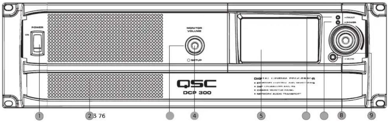
- Power "on" switch
- 4" full-range monitor speaker
- Monitor volume and parameter adjust (function depends on operating mode) Monitor mode: controls level to DCP front panel speaker in monitor mode Setup mode: provides parameter control in setup mode
- Setup mode LED - illuminates green when DCP is in setup mode
- Touch control LCD (4.3" 16:9 color display)
- Fault LED - illuminates red when load faults or system errors are detected
- Power "on" LED - illuminates green when AC power is applied
- Mute button - illuminates red when engaged, illuminates green when disengaged
- Auditorium volume control - global level control for all audio outputs
DCP 300 Rear Panel Features
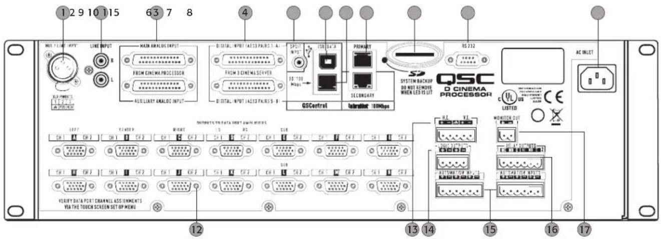
- Mono analog input - accepts microphone or line level signals (with phantom power)
- Stereo analog inputs – accepts line level signals
- Analog audio inputs – connect to D-Cinema server or film processor with analog outputs
• Top connector: channels 1 through 8
• Bottom connector: 6 auxiliary channels
- Digital audio inputs – connect to D-Cinema server or fi lm processor with digital outputs
• Top connector: AES3 pairs 1 through 4 (digital audio channels 1 through 8)
• Bottom connector: AES3 pairs 5 through 8 (digital audio channels 9 through 16)
-
S/PDIF input - multi-channel digital input for non-sync/alternative content
-
USB Type B port for DCP configuration and management via direct connection
- 10/100 Mbps Ethernet port – for QSControl™, 3rd party, or SNMP management and remote access
- 100 Mbps Ethernet ports - CobraNet™ audio network - Primary and Secondary (backup)
- SD memory card – device configuration storage supports quick unit replacement
- Serial communications port - 3^rd party control/automation via RS232
- IEC inlet - AC mains power connector with cord lock
- DataPort interface for QSC amplifiers – supports up to fourteen single port amplifiers
- Hearing impaired and visually impaired special mix outputs
- CMOS compatible logic outputs – for use as automation triggers, alerts, system status
- Automation inputs – digitally sampled analog control inputs (control presets, levels etc.)
- Relay outputs - mechanically decoupled control outputs (curtain, lighting control etc.)
- Audio monitor output - tap from front panel monitor speaker (post DSP, pre amplifi er)
DCP 200 Front Panel Features
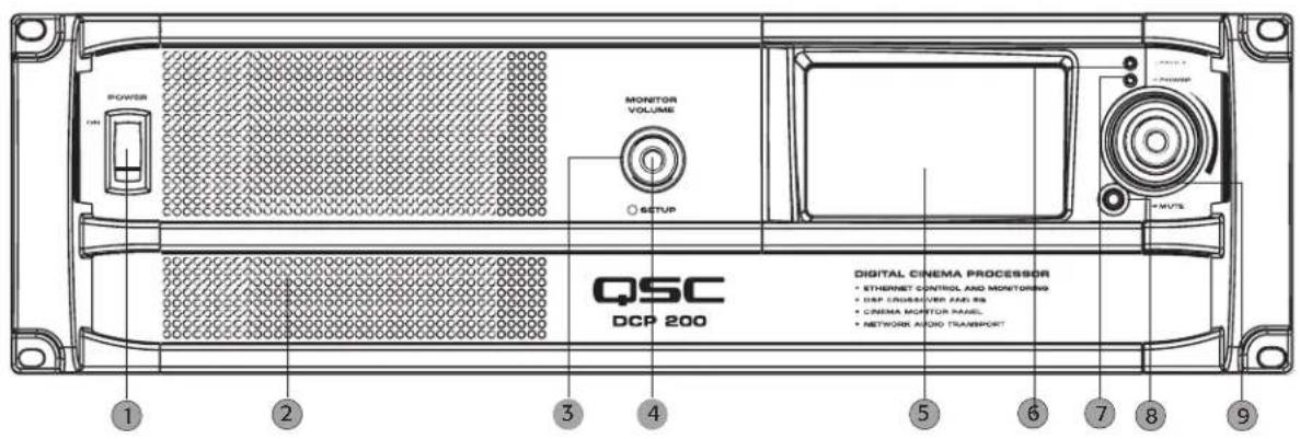
- Power "on" switch
- 4" full-range monitor speaker
- Monitor volume and parameter adjust (function depends on operating mode) Monitor mode: controls level to DCP front panel speaker in monitor mode Setup mode: provides parameter control in setup mode
- Setup mode LED – illuminates green when DCP is in setup mode
- Touch control LCD (4.3" 16:9 color display)
- Fault LED – illuminates red when load faults or system errors are detected
- Power "on" LED - illuminates green when AC power is applied
- Mute button – illuminates red when engaged, illuminates green when disengaged
- Auditorium volume control - global level control for all audio outputs
DCP 200 Rear Panel Features
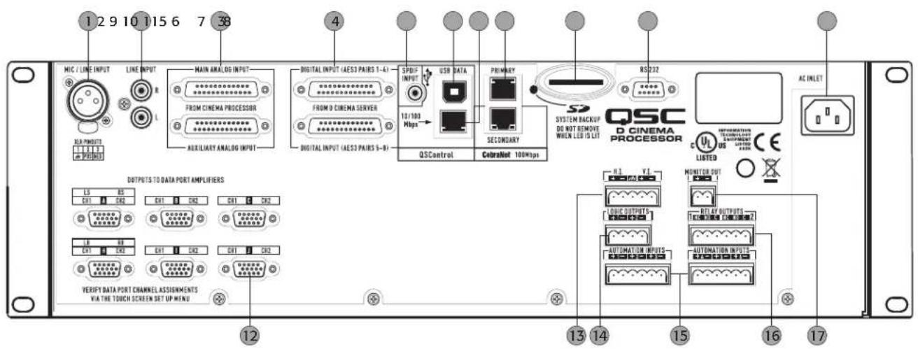
- Mono analog input – accepts microphone or line level signals (with phantom power)
- Stereo analog inputs – accepts line level signals
- Analog audio inputs – connect to D-Cinema server or film processor with analog outputs
• Top connector: channels 1 through 8
• Bottom connector: 6 auxiliary channels
- Digital audio inputs – connect to D-Cinema server or film processor with digital outputs
• Top connector: AES3 pairs 1 through 4 (digital audio channels 1 through 8)
• Bottom connector: AES3 pairs 5 through 8 (digital audio channels 9 through 16)
- S/PDIF input - multi-channel digital input for non-sync/alternative content
- USB Type B port for DCP configuration and management via direct connection
- 10/100 Mbps Ethernet port – for QSControl™, 3rd party, or SNMP management and remote access
- 100 Mbps Ethernet ports - CobraNet™ audio network - Primary and Secondary (backup)
- SD memory card - device configuration storage supports quick unit replacement
- Serial communications port - 3^rd party control/automation via RS232
- IEC inlet - AC mains power connector with cord lock
- DataPort interface for QSC amplifiers – supports up to six single port amplifiers
- Hearing impaired and visually impaired special mix outputs
- CMOS compatible logic outputs – for use as automation triggers, alerts, system status
- Automation inputs - digitally sampled analog control inputs (control presets, levels etc.)
- Relay outputs - mechanically decoupled control outputs (curtain, lighting control etc.)
- Audio monitor output - tap from front panel monitor speaker (post DSP, pre amplifier)
DCP 100 Front Panel Features
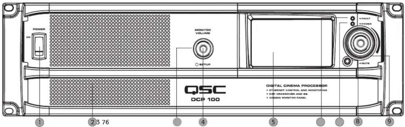
- Power "on" switch
- 4" full-range monitor speaker
- Monitor volume and parameter adjust (function depends on operating mode) Monitor mode: controls level to DCP front panel speaker in monitor mode Setup mode: provides parameter control in setup mode
- Setup mode LED - illuminates green when DCP is in setup mode
- Touch control LCD (4.3" 16:9 color display)
- Fault LED - illuminates red when load faults or system errors are detected
- Power "on" LED - illuminates green when AC power is applied
- Mute button – illuminates red when engaged, illuminates green when disengaged
- Auditorium volume control - global level control for all audio outputs
DCP 100 Rear Panel Features
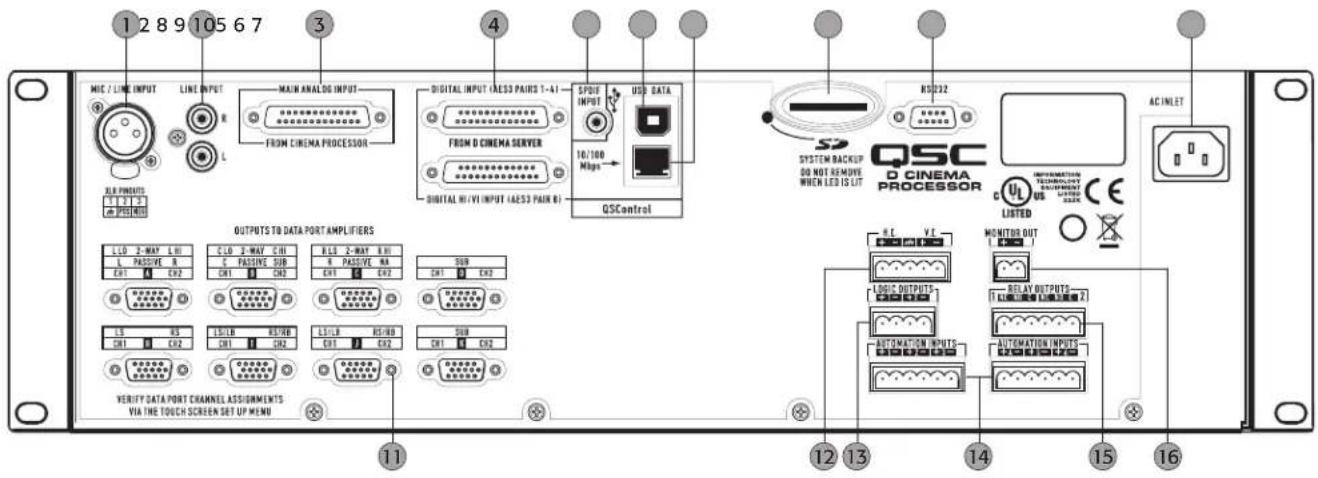
- Mono analog input – accepts microphone or line level signals (with phantom power)
- Stereo analog inputs – accepts line level signals
- Analog audio inputs – connect to D-Cinema server or film processor with analog outputs Top connector: Main Analog Input: channels 1 through 8
- Digital audio inputs – connect to D-Cinema server or film processor with digital outputs Top connector: AES3 pairs 1 through 4 (digital audio channels 1 through 8) Bottom connector: AES3 pair 8 (digital audio channels 15 and 16 for H.I./V.I.)
- S/PDIF input - multi-channel digital input for non-sync/alternative content
- USB Type B port for DCP configuration and management via direct connection
- 10/100 Mbps Ethernet port – for QSControl™, 3rd party, or SNMP management and remote access
- SD memory card - device configuration storage supports quick unit replacement
- Serial communications port - 3 rd party control/automation via RS232
- IEC inlet - AC mains power connector with cord lock
- DataPort interface for QSC amplifiers – supports up to eight single port amplifiers
- Hearing impaired and visually impaired special mix outputs
- CMOS compatible logic outputs – for use as automation triggers, alerts, system status
- Automation inputs – digitally sampled analog control inputs (control presets, levels etc.)
- Relay outputs - mechanically decoupled control outputs (curtain, lighting control etc.)
- Audio monitor output - tap from front panel monitor speaker (post DSP, pre amplifier)
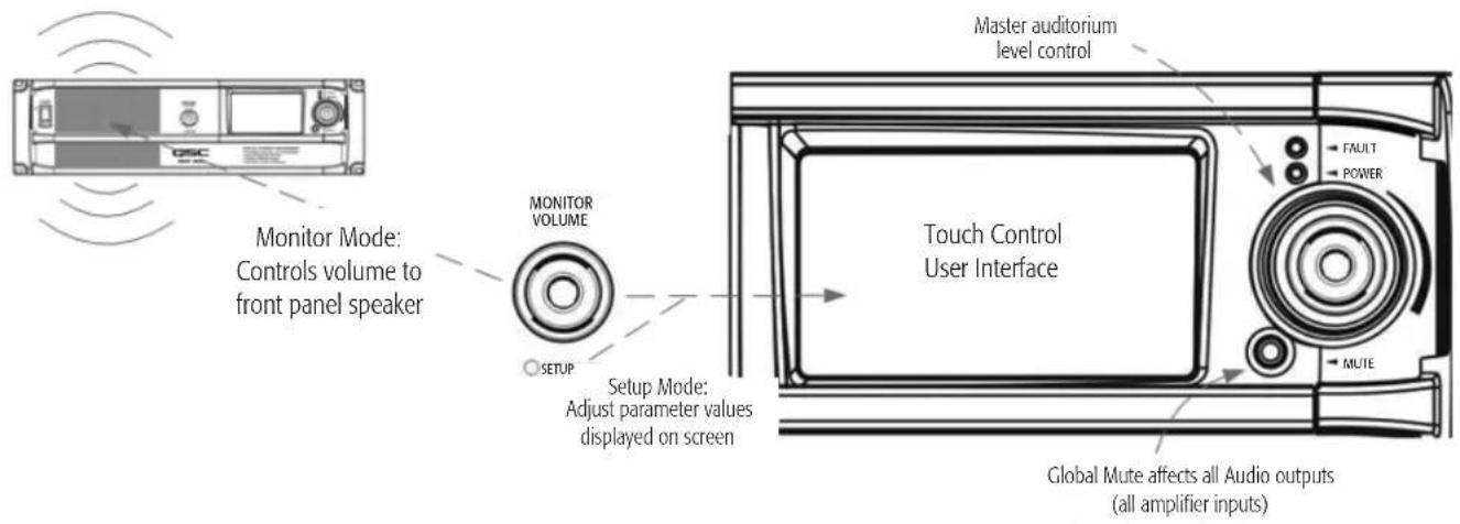
Front Panel User Interface Details
Front Panel UI
The DCP front panel includes a 480 x 272 pixel, 4.3", color TFT display with a touch control interface and a 16:9 wide screen aspect ratio. The touch control "user interface" allows authorized system operators to recall previously configured presets, adjust levels, change monitor tap points etc. The "Monitor Volume" knob is used to manipulate these parameters when the DCP is in "setup mode" (indicated when the "SETUP" LED in the middle of the Monitor Volume knob is illuminated green).
The Monitor Volume is also used to change the level of the amplified monitor signal feeding the DCP front panel speaker when the DCP is in "monitor mode" (indicated when the "SETUP" LED is not illuminated).
The global "Mute" button, when engaged, mutes all audio outputs. Engagement of the Mute button is indicated when the red LED in the mute button cap is illuminated. Normal operation (non-muted) is indicated through illumination of the Mute button cap with a green LED.
The large rotary encoder knob to the right of the touch control LCD is the master level control for the auditorium sound system. Adjusting this control manipulates the level of the audio signal fed to all audio outputs.
Setup Overview
Initial configuration of the DCP is performed through QSC's DCP Manager™ software, which must be installed on a Windows® PC or laptop computer. Once the software is installed on the computer, the computer can then be connected to the DCP product via a USB connection.
A system designer would typically begin high-level configuration by defining the basic system topology and distribution of audio within the DCP Manager application. This involves selecting the audio sources for the DCP program inputs, auditorium sound format, amplification and speaker design and whether additional devices (such as BASIST™ devices) are included in the system design for the purposes of expanding the quantity of DataPort outputs or for locating the amplifiers remotely for example: outside of the projection booth... behind the projection screen. Presets can be created to accommodate multiple audio sources or distribution topologies (i.e., to support different configurations for the main theatre presentation and for alternative content/non-sync audio) and/or to support multiple auditorium mixes or multi-use applications.
Once the high-level configuration is complete, the rest of system can be connected to the DCP and/or powered up and completion of the DSP configuration, assignment of levels, application of architectural delay etc. and system tuning can commence.
Note that recalling of system presets and adjustment of system parameters such as output and monitor levels, monitor tap points etc. can be made through the front panel user interface (the touch control LCD and associated rotary encoders) by authorized users.
The Setup Overview on the following pages is a general application guide showing the installation steps required for a basic system. Refer to the Help Files in DCP Manager and the QSControl.net™ suite of applications for detailed setup and configuration instructions and for system examples. The QSC Cinema Products web pages are also a good source of information for application notes and system design assistance.
Setup Overview
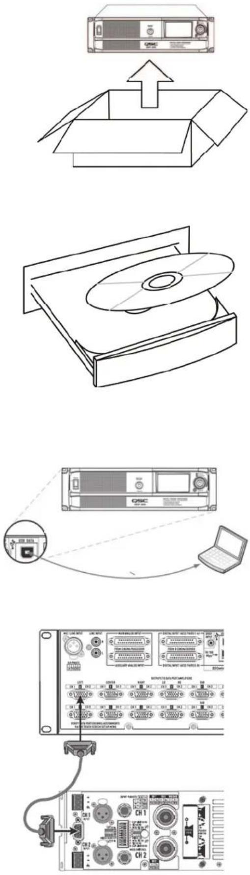
1. Unpack Carton
Remove your DCP product from its carton and inspect it carefully. Make sure that the carton contents are complete and that there are no signs of shipping damage. Retain all packaging for future unit storage or for the unlikely event that service is needed.
2. Install Software
Load the DCP Manager disc into a CD-ROM or DVD drive on a Windows ^® PC or laptop computer. Follow the installation instructions displayed on your computer's screen.
Note: DCP Manager must be installed before connecting the DCP to a Windows PC or laptop computer.
3. Confi gure DCP
After DCP Manager is installed, connect a USB cable between the DCP and the computer. Turn the DCP on, launch DCP Manager and follow the prompts on screen. Refer to the Help Files for instructions on how to confi gure the basic operating parameters of the DCP (source inputs, format, presets, etc).
4. Attach Amplifiers
Connect DataPort outputs on the DCP rear panel to DataPort inputs on QSC's DCA or PL3 Series amplifiers using QSC approved DataPort cables.
Setup Overview
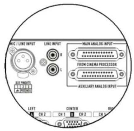
5. Connect Audio
Connect cinema audio sources to the appropriate DCP rear panel input connectors. Main sources can come from digital content servers or analog fi lm processors. Additional analog and digital inputs are provided for alternative content sources, live feeds, DVD players, mic/ paging sources etc.
Connect the Hearing Impaired and Visually Impaired special mix outputs and/or the Monitor Output feed to appropriate external devices as needed.
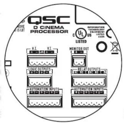
6. Connect Automation
Connect appropriate external control devices to the DCP's automation Inputs. Connect the Logic Outputs and/or Relay Outputs to any external devices to be controlled.
7. Complete Installation
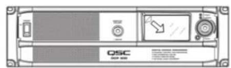
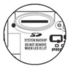
Remove protective fi lm covering the touch panel LCD surface. Insert the included SD Card into the rear panel receptacle. The SD Card provides DCP configuration storage for quick unit service/replacement.
8. Tune System
Once the basic DCP operating configuration is defined and all of the connections are in place, it's time to power up the rest of the rack, complete the DSP setup, tune the system and run through final check.
Refer to additional information in this Hardware User Manual and in the software Help Files for further setup and configuration details to complete this step.
natural_image
Simple line drawing of a tuning fork (no text or symbols)Configuration and Networking
The DCP offers a variety of accessibility options for configuring and managing the product and an entire cinema sound system locally or remotely. Local DCP configuration and system management are provided through directly applied connections to the DCP via universal serial bus (USB), the DCP front panel touch-control LCD or through a local Ethernet link (QSControl™). Remote and system-wide management are possible through more sophisticated network implementations and/or via wide area network (WAN) topologies, Internet access or 3^rd party subscription services that make use of the DCP 3^rd party API or SNMP.
Basic configuration of the DCP product is performed through the USB interface on the product rear panel. The system designer connects to the DCP's rear panel USB port with a Windows laptop or PC running the DCP Manager software application. DCP Manager offers all the setup tools and system management objects to configure the auditorium audio format, selection of audio source material, configure the DSP signal path, apply crossovers, EQ etc., define the routing of audio to the amplifiers, define the system speakers and speaker processing etc. Once the basic configuration is complete, the system designer can define custom Presets that can be recalled for different auditorium setups. For example, a Preset can be created for the primary presentation content. Another Preset can be created for non-sync or alternative content. And yet another Preset can be created for live application use such as seminars or corporate events. Once these Presets are created they become accessible via the DCP front panel touch-control LCD.
In addition to basic configuration, DCP Manager can be used to monitor health, status and performance of the local system (the directly connected DCP) via the product's rear panel USB interface.
USB connection to DCP
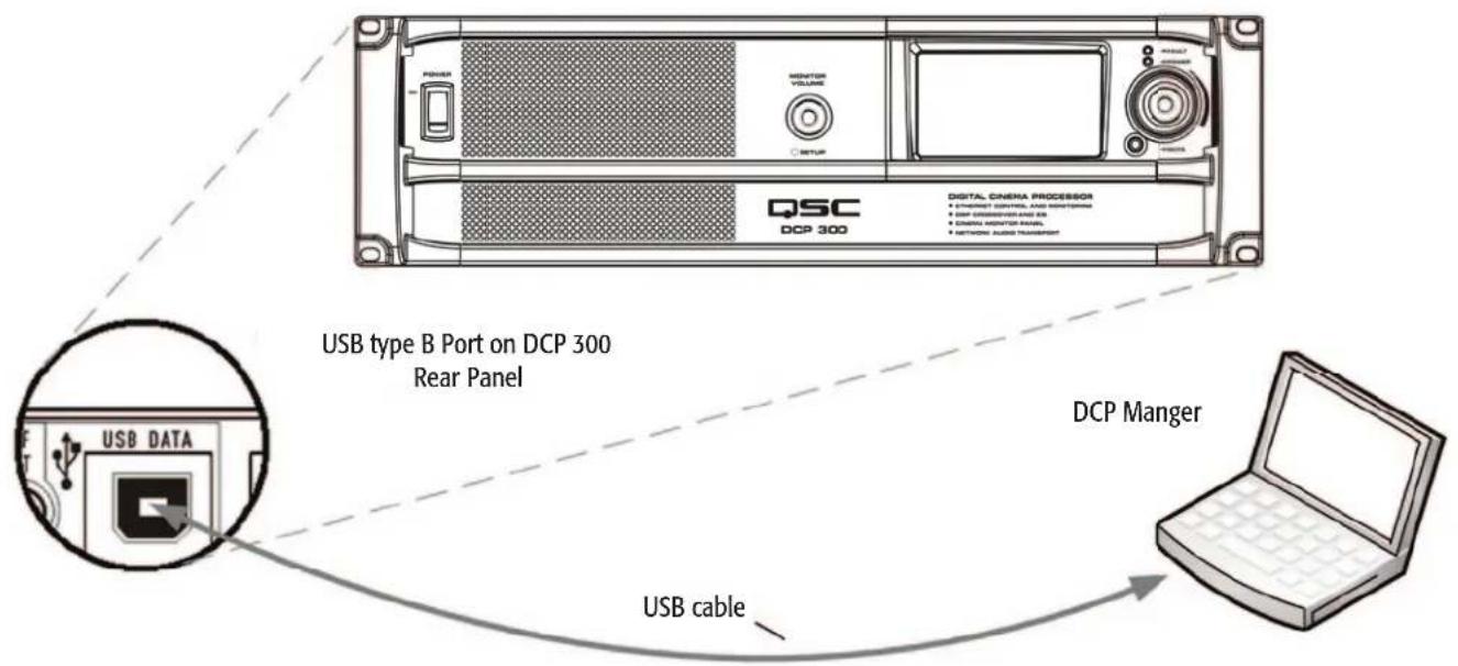
The image above illustrates a Windows ^® laptop connecting directly to the DCP via the product's rear panel USB Type B port. The Windows machine is running QSC's DCP Manager Application, which is used to confi gure the DCP.
Once the DSP signal chain and audio format are configured, the DCP can be connected to an Ethernet LAN for local or remote management using the QSControl.net™ suite of applications or via a custom application or control system using the DCP 3rd Party API. Alternately, an SNMP-based management system may be used to monitor and control the DCP.
A local Ethernet connection to a Windows laptop or PC that is running QSC's Venue Manager Application provides the system designer with access to status, health and performance of the local system. Changes to Presets, audio levels and some automation control objects can be made through Venue Manager access.
DCP firmware updates can also be performed through the Venue Manager Application. For more venue-specific needs, QSC's QSCreator Application allows the system designer to create custom control screens with varying levels of password protection (authentication rights). QSCreator screens can be as elaborate as the system designer's imagination and can be created to depict the physical layout of the auditorium or the entire cinema complex.
Since the QSControl.net™ suite of applications provide accessibility to the DCP's network interface, these applications can be used to manage an entire sound system consisting of multiple DCP products, QSC amplifiers, QSC speakers and other QSC network enabled products such as BASIS, RAVE and DSP 300 series products. Management can be localized (within the theatre complex) or remote, depending on the network implementation deployed. Alternately, an SNMP management system may be used to monitor and control DCP products.
Local Ethernet connection to DCP
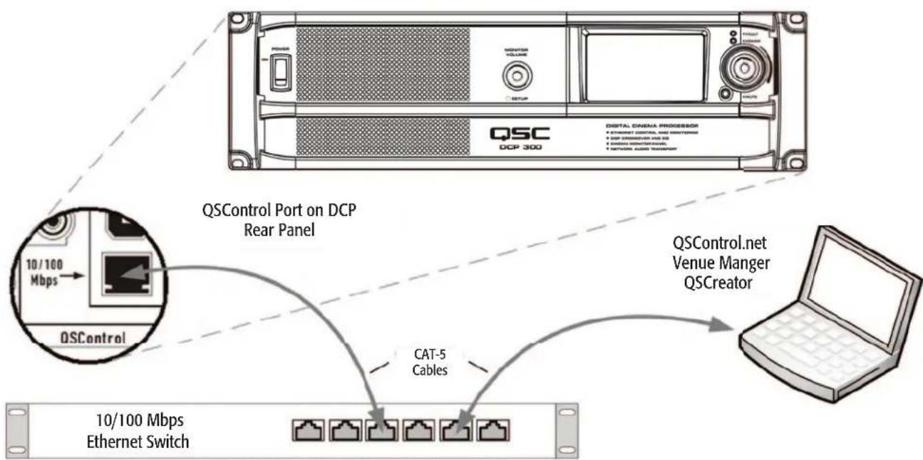
flowchart
graph TD
    A["QSControl"] -->|10/100 Mbps| B["QSControl Port on DCP Rear Panel"]
    B --> C["CAT-5 Cables"]
    C --> D["10/100 Mbps Ethernet Switch"]
    D --> E["QSControl.net Venue Manger QSCreator"]
    E --> F["Computer with Ethernet Switch"]
    style A fill:#f9f,stroke:#333
    style B fill:#ccf,stroke:#333
    style C fill:#cfc,stroke:#333
    style D fill:#fcc,stroke:#333
    style E fill:#cff,stroke:#333
    style F fill:#ffc,stroke:#333
The image above illustrates a Windows ^® laptop connecting to the DCP via a network switch. The DCP is also connected to the network switch via its rear panel QSControl ^™ port. The Windows ^® machine is running QSC's QSControl.net suite of applications, which includes Venue Manager, QSCreator, Notify and the QSControl ^™ 3 ^rd Party API.
Unpacking
There are no special unpacking precautions. However, it is recommended that you keep the original packing materials for reuse in the rare event that service is required. If service is required and the original packing material is not available, ensure that the unit is adequately protected for shipment (use a strong box of appropriate size, sufficient packing/padding material to prevent load shifting or impact damage) or call QSC's Technical Services Group for replacement packing material and a carton.
DCP Product Carton Contents
- DCP product
- Hardware User Manual
- DCP software CD(s)
- IEC power cord and wire cord retainer
- Euro style connector plug kit
- SD card (2 GB)
- Warranty card
Mounting
The DCP product is designed to be mounted in a standard 19" (480 mm) equipment rack and requires 3 vertical rack spaces (refer to IEC 60297 for additional rack dimensions and design details). Rack mounting provides the DCP with stability and a convenient means for dressing the cables connecting to the product. Some rack systems also provide climate control and/or conditioned power.
Rack mount the DCP product by supporting it from underneath while aligning the four front panel mounting holes (in the rack ears) with the threaded screw holes in the rack rails. Install all four mounting screws and washers and tighten securely. The DCP product comes with rear rack support ears. Ensure that these rear mounting points are securely fastened to rear rack rails or rack side walls.
Computer Requirements
Your PC or laptop must meet the following minimum requirements:
- IBM PC compatible computer (Windows PC)
- Intel Pentium 4 CPU or better
- CPU speed of 2.0 GHz or faster
- 1 GB of RAM or greater
- Hard drive with at least 1 GB of space available
- Display resolution of at least 1024 x 768
- CD-ROM drive for installing DCP 300 software
- Windows ^® XP Pro, Windows Vista ^® , Windows ^® 7 operating System (Supports 32 or 64 bit systems)
In addition to these minimum requirements, your PC or laptop must have a 10/100 or 10/100/1000 Mbps Network Adapter (NIC) in order to join a QSControl™ network.
Software Installation
Installing the DCP Manager™ and QSControl.net™ suite of software applications is easy. All you need to do is choose the folder where the application is to reside (the default setting is acceptable for most users).
- Start your Windows ^® PC or laptop
- Close any running applications
- Place the DCP Manager software CD into your CD-ROM drive.
- The DCP Manager software should auto-run. If not, select run from the start menu. Browse to the file named setup.exe on your CD-ROM drive.
-
Click the Install DCP Manager button
-
Follow the on-screen prompts/instructions
- Repeat steps 1 through 6 to install OSControl.net™
USB Driver Warning
DCP Manager must be installed on your PC or laptop prior to connecting it to the DCP product. This ensures that the USB driver is properly installed on your PC or laptop prior to establishing a connection to the DCP product via the computer's USB port.
Configuring the DCP
DCP Manager™ is used to configure the DCP product. This includes configuring the device properties, the DSP objects, audio and control I/O and Presets. The network communications properties and audio networking features can also be configured using DCP Manager™ so that all networking properties are in place before the DCP is added to a local area network (if your deployment requires networking). Alternately the DCP is accessible via SNMP remote management.
Once the DCP product is configured via DCP Manager™, the QSControl.net™ suite of applications (Venue Manager, QSCreator™, Notify and the QSControl™ 3rd Party API) can then be used to manage one or more DCP products over a local area network.
Refer to the information in the DCP Manager™ and QSControl.net™ application Help Files for additional information on product configuration, management and network connectivity.
Connections
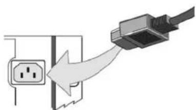
AC Power Cord
Insert the molded receptacle of the AC power cord into the AC power inlet on the back of the DCP product. Plug the AC line connector into an AC outlet. The power supply on the DCP product will accept from 100 to 240V, 50 to 60 Hz. If a different type of IEC power cord is required than that supplied with the product, consult QSC's Technical Services Group.
natural_image
Diagram showing a plug inserted into an outlet with a cable being inserted (no text or symbols present)QSControl™ Network
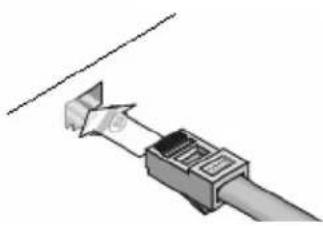
Connect one end of a data communications cable terminated with an RJ45 plug into the QSControl™ receptacle on the rear panel of the DCP product. Ensure that the lock tab on the cable engages with the RJ45 receptacle on the DCP rear panel connector. Note: data communications cabling must be rated CAT-3 or better for 10 Mbps network connections or rated CAT-5 or better for 100 Mbps network connections.
natural_image
Diagram of a USB connector with a cable inserted, showing internal structure and cable extension (no text or symbols)CobraNet Network
(DCP 200 and DCP 300 models only)
Connect one end of a data communications cable terminated with an RJ45 plug into the CobraNet™ Primary receptacle on the rear panel of the DCP product. Ensure that the lock tab on the cable engages with the RJ45 receptacle on the rear panel DCP connector. For systems requiring redundant network connections, connect a second data communications cable terminated with an RJ45 plug into the CobraNet™ Secondary receptacle on the rear panel of the DCP product. Note: data communications cabling must be rated CAT-5 or better for all CobraNet™ connections.
Connections Continued
Hearing and Visually Impaired Outputs
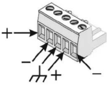
The Hearing Impaired and Visually Impaired special mix outputs are balanced outputs that are combined into a single 5-terminal Euro style (a.k.a. Phoenix) receptacle. This combo receptacle includes a common ground for both the H.I and V.I. outputs. Terminate the mating 5-terminal Euro plug and insert it into the DCP rear panel receptacle as shown in the image to the right. The DCP rear panel label provides a pin-out of the receptacle signals. Note: a standard 3-terminal plug may be used if only one output is required.
Automation Inputs, Logic Outputs, Monitor Output
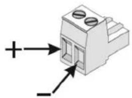
The automation inputs, logic outputs and monitor output all use a 2-terminal or 6-terminal Euro style (a.k.a. Phoenix) receptacle. The Automation Inputs can be connected to relay contacts, a switch or a 10K potentiometer. Logic Outputs are CMOS compatible. And the Monitor Output is a single-ended balanced impedance source. All connections require a 2-terminal or 6-terminal Euro style plug. The DCP rear panel label provides all necessary signal information. The negative terminal of each receptacle is at chassis potential.
Relay Outputs
Two relay outputs are provided via two 3-terminal Euro style (a.k.a. Phoenix) receptacles. Relay contacts are floating and rated for 30 VDC at 1A. Each output includes one common terminal, one normally open contact (N.O.) and one normally closed (N.C.) contact. These terminals are labeled C, NO and NC, respectively on the DCP rear panel. When the relay is not energized, the C terminal is connected to the NC contact and the NO contact is not connected. When the relay is energized, the C terminal is connected to the NO contact and the NC contact is not connected.
DataPorts
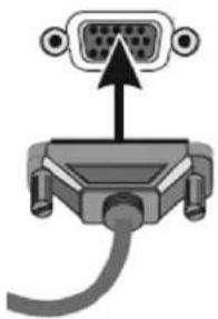
QSC DataPorts on the DCP rear panel are intended to interface to QSC amplifiers with v1 DataPorts. These are the all-capable DataPorts, which are included on DCA and PL3 series amplifiers. All DataPorts use the HD15 connector format and connect to QSC amplifiers via data communications cables having male HD15 connectors on both ends. These are commonly referred to as VGA cables. Note: though many off-the-shelf VGA cables may work with satisfactory results, the QSC DataPort specification requires that all conductors be present and that all audio I/O conductors be shielded. Therefore, only QSC supplied DataPort cables should be used. A variety of lengths are available through QSC's Technical Services Group. To connect a DataPort cable between a DCP DataPort and an amplifier DataPort, attach the cable's male connectors to the HD15 ports and finger tighten the thumb screws on the connectors.
Ancillary Interfaces
A single Mic/Line Input is accessible on the DCP rear panel. This input can be used for mono non-sync sources or for connecting a microphone for local paging or announcements into the auditorium or to support various corporate or live events requiring a microphone. Phantom power may be enabled via DCP Manager™ configuration or via the DCP front panel interface. The Mic/Line Input uses a standard 3-conductor XLR receptacle.
L/R analog line input connectors and a multi-channel digital S/PDIF input are accessible on the DCP rear panel. These RCA connectors accommodate non-sync sources appropriate for alternative content, advertising, corporate or live event feeds.
A USB Type B interface is provided for directly connecting to a Windows ^® PC or laptop. All configuration and local management of the DCP via DCP Manager software is performed through this portal.
Note: all ancillary interfaces use standard cables that are readily available through retailers specializing in computer equipment, musical equipment, pro audio or home electronics.
natural_image
Diagram of a 3D electrical connector with labeled terminals (+ and -), showing pin layout and mounting points (no text or symbols beyond basic labels)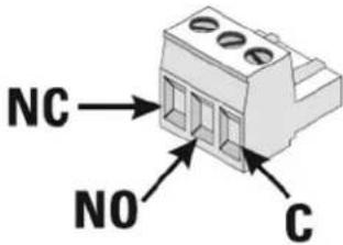
natural_image
Diagram of a VGA connector with an arrow pointing to the top panel (no text or symbols present)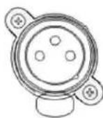
SPDIF INPUT
LINE INPUT



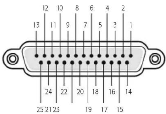
Main Analog Input Connector Pinout
25-pin male D-Sub to 25-pin male D-Sub
| Pin # Description | Pin # Description | |
| 1 Chassis ground | 14 Left - | |
| 2 Left + | 15 Chassis ground | |
| 3 Left extra - | 16 Left extra + | |
| 4 Chassis ground | 17 Center - | |
| 5 Center + | 18 Chassis ground | |
| 6 Right extra - | 19 Right extra + | |
| 7 Chassis ground | 20 Right - | |
| 8 Right + | 21 Chassis ground | |
| 9 Chassis ground | 22 Chassis ground | |
| 10 Surround left - 23 Surround left + | ||
| 11 Surround right - | 24 Surround right + | |
| 12 | Subwoofer - | 25 Subwoofer + |
| 13 | Chassis ground | Shell Chassis ground |
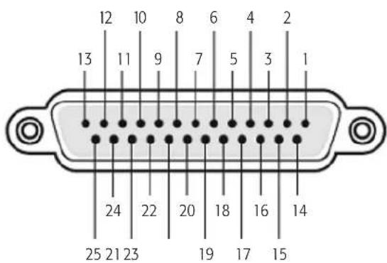
Auxiliary Analog Input (Surround EX) Pinout
25-pin male D-Sub to 25-pin male D-Sub
Pin # Description Pin # Description
1 (not used) 14 Left extra +
2 (not used) 15 Left extra -
3 Back surr left - 16 Back surr left +
4 (not used) 17 (not used)
5 (not used) 18 (not used)
6 Back surr right - 19 Back surr right +
7 (not used) 20 (not used)
8 (not used) 21 (not used)
9 Right extra + 22 Right extra -
10 Surround left - 23 Surround left+
11 Surround right - 24 Surround right +
12 (not used) 25 (not used)
13 (not used) Shell Chassis ground
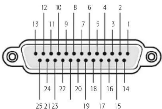
Digital (AES3) Input Connector Pinout
25-pin male D-Sub to 25-pin male D-Sub
Pin # Description Pin # Description
1 AES 1: Gnd 14 AES 1: Pos
2 AES 1: Neg 15 AES 2: Gnd
3 AES 2: Pos 16 AES 2: Neg
4 AES 3: Gnd 17 AES 3: Pos
5 AES 3: Neg 18 AES 4: Gnd
6 AES 4: Pos 19 AES 4: Neg
7 (not used) 20 (not used)
8 (not used) 21 (not used)
9 (not used) 22 (not used)
10 (not used) 23 (not used)
11 (not used) 24 (not used)
12 (not used) 25 (not used)
13 (not used) Shell Chassis ground
Main Analog Input
Auxiliary Analog Input
Digital Input
(the connector providing AES3 pairs 1-4 and the connector providing AES3 pairs 5-8 are wired the same and with the same pair sequence)
Specifications
The following specifications are based on the DCP 300. The DCP 100 and DCP 200 vary only in some functionality, and quantity of connectors. Refer to the individual sections in this document for more information.
| Dimensions (H/W/D): 5.25" x 19" x 15" Audio Performance (Main Analog Input) | |||
| Line voltage requirements 100 VAC - 240 VAC, 50/60 Hz A/D conversion 24-bit delta-sigma, 48 kHz | |||
| Accessories included | 6 ft UL/CSA line cord, User Manual Software CD, Connector Kit | Dynamic range (unweighted) >105 dB | |
| Front Panel Controls Input stage type Active balanced | |||
| Power switch Rocker switch Input impedance 22 k Ohms | |||
| Mute control Push button Max analog input level +14.2 dBu (4.0 Vrms) | |||
| Auditorium fader | Rotary encoder | THD+N at +4 dBU and 2 dB below clip (per AES-17) | <0.005% |
| Monitor volume/parameter adjust | Rotary encoder | Audio Performance (Mic/Line Input) | |
| Menu-driven LCD | Touch control LCD | A/D conversion | 24-bit delta-sigma, 48 kHz |
| Indicators | Dynamic range (unweighted) >105 dB | ||
| Mute engage/disengage | Button illumination | Input stage type | Active balanced |
| Monitor level/parameter focus | Encoder knob illumination | Input impedance | 6.81 k Ohms |
| Power on indicator | Green LED | Max analog input level | +28 dBu (19.45 Vrms) |
| Fault detect indicator | Red LED | CMRR typical (max) | 20 Hz - 20 kHz >60dB (>50dB) |
| Rear Panel Connectors | THD+N at 2 dB below clip (per AES-17) | <0.05% | |
| D-Cinema input group 1 | DB-25 - AES3/EBU channels 1-8 | Audio Performance (Digital Input: AES/EBU) | |
| D-Cinema input group 2 | DB-25 - AES3/EBU channels 9-16 | Input type | Balanced |
| Main analog input | DB-25 - Analog audio channels 1-8 | Input impedance | 120 Ohms |
| Extended surround input | DB-25 - Surround and Le/Re Channels | Input sample rate | 48 kHz or 96 kHz |
| Universal Mic/Line input | XLR - Mic (+ phantom pwr) or line level | Audio Performance (DataPort Outputs) | |
| S/PDIF input | RCA - Stereo digital audio interface and Lt/Rt Matrix | Output level range | +6 dB to -18 dB in .1 dB steps |
| RCA (L/R) inputs | RCA (2) - Stereo Left and Right and Lt/Rt Matrix | Dynamic range (unweighted): | >105 dB |
| DataPort outputs | HD-15 (14) - QSC amplifier interface | THD+N at +12dBu input level (per AES-17) | <.005 % |
| Automation inputs | 2-pin Euro-style (x6) - 8-bit resolution | Frequency response | 20 Hz to 20 kHz |
| Logic output | 2-pin Euro-style (x2) - CMOS levels | D/A conversion | 24-bit delta-sigma, 48 kHz |
| Relay outputs | 3-pin Euro-style (x2) - max 30 VDC DSP Performance | ||
| Monitor output | 2-pin Euro-style (x1) - line out | Filter topology | 24-bit digital IIR |
| H.I./V.I. output | 5-pin Euro-style (x1) - common GND | Crossover filters | Linkwitz-Riley or Butterworth (6 - 48 dB/octave) |
| Serial Control | DB-9 RS-232 Serial Interface | Parametric EQs | Digital bandpass filter with ±20 dB of boost/cuL Q is programmable in 1/10th octave steps from 1/20th to 4 octaves |
| USB Type B port | Config and management interface | Graphic EQ | 28 band 1/3 octave with up to ±12 dB cut/boost |
| QSControl RJ45 | 10/100 Mbps network management | Bass | Digital shelf filter with up to ±10 dB of cut/boost programmable knee |
| CobraNet RJ45s | 100 Mbps primary/backup network audio | Treble | Digital shelf filter with up to ±10 dB of cut/boost programmable knee |
| SD card receptacle | Configuration memory card (1 GB min) | ||
| Subsonic (high-pass) filter | Digital high-pass filter with Q programmable as flat (.707) or B6 boost (2.0) from 15 Hz to 50 Hz | Automation inputs | |
| CD Horn EQ | Digital shelf filter with up to ±10 dB of cut/boost programmable from 20 Hz to 20 kHz | Input type OMNI (discrete state or potentiometer) | |
| Screen EQ | Digital shelf filter with up to ±10 dB of cut/boost programmable from 20 Hz to 20 kHz | Compatible sources | Accepts contact closure (switches, relays) or 10K pot. Input is sampled and converted to 8-bit digital value |
| All pass filter | 2nd order all pass filter programmable from 20 Hz - 20 kHz | Logic Outputs | |
| Band polarity Normal, inverted Output type Two-state logic | |||
| Band delay Programmable in 21μs steps from 0 ms to 10 ms Compatible CMOS compatible output levels | |||
| Channel delay | Programmable in 1ms steps from 0 ms to 175 ms (0 to 4 frames) | Relay outputs | |
| Master delay | Programmable in 1ms steps from 0 ms to 420 ms (0 to 10 frames) | Output type Mechanical relay contacts | |
| Mute Individual channel mutes, global mute Compatible | Max 30VDC output at 1A. Can be wired as N.O. or N.C | ||
| Bass management | Weighted sum of screen channels may be low pass filtered and mixed with sub output | Liquid crystal display | |
| Surround bass management | Weighted sum of surround channels may be low pass filtered and mixed with aux output A. | Display type Active color TFT | |
| Amplifier A.C. Control | All amps power on with DCP activation and can be placed into standby via user interface | Display area dimensions 4.3" diagonal viewing area | |
| Monitor speaker Format 16 x 9 | |||
| Speaker | 4" full-range | Touch panel type | Resistive 4-wire |
| Impedance 4 Ohms | Audio network | ||
| Amplifier output power | 10 watts Class D | Protocol | CobraNet version 2 protocol |
| Frequency response | 20 Hz - 20 kHz (± 2 dB) | Data rate | 100 Mbps (Fast Ethernet) |
| Dynamic processing | 1.5:1 compression | Ports | 1 Primary, 1 Backup (auto-failover) |
| H.I. and V.I. impaired outputs | Connection requirements | Cat-5 UTP cable or better (100m maximum length), direct connection to wired network switch ports only, dedicated LAN or VLAN | |
| Output stage type | Single ended (balanced Z) | QSControlTM network / SNMP | |
| Output impedance | 50 Ohms | Protocol | Standard TCP/IP implementation over Ethernet or Fast Ethernet. 3rd party interface may use UDP/IP or TCP/IP. |
| Nominal output level | -11.8 dBu (200 mVrms) | Data rate | 10/100 Mbps |
| Loading requirements | Rmin = 2k Ohms, Cmax = 4nF | Connection requirements | Cat-5 UTP cable or better (100m maximum length), direct connection to wired network switch ports only, dedicated LAN or VLAN |
Appendix A:
DCP Serial Port Automation Control Protocol Rev 2.0 Description
This appendix describes the serial port automation control protocol for managing QSC's DCP Digital Cinema Processor. Serial port automation is handled via ASCII text commands sent via RS-232 from an external device. All commands must be terminated with a CR [0Dh] or LF[0Ah].
NOTE: Settings manipulated via serial port automation commands may be overridden or modified by commands issued from the DCP front panel display, by commands sent over the network using QSC's Third Party Control Protocol, or by triggers coming in through other automation inputs on the DCP rear panel.
1.1 Communication Settings
The serial port settings required to communicate with the serial interface on the DCP are as follows:
• Baud rate of 115200 bits per second
• 8 Data Bits
- No Parity
- 1 Stop Bit
- Flow Control: none
• Straight through cable (not a null modem)
1.2 Command Protocol
A communication terminal program such as Hyper Terminal can be used for initial testing of the DCP automation commands. After connecting the serial port cable (no null modem) and configuring a communication session you should see the following command prompt indicating that the DCP unit is ready to accept serial automation commands, (you may need to use a
cmd>
1.3 Automation Command Reference
The following serial commands are currently supported by all DCP products. Serial commands prefixed by "dcp100" and "dcp200" are also supported by all DCPs.
dcp300preset
Selects the preset specified (1 - 32). If no preset number is entered following the '=' character, then the currently selected audio preset is returned. Examples:
To select preset 1:
cmd>dcp300preset=1
Return value: dcp300preset=1
To query currently selected audio preset (presets 1-16): cmd>dcp300preset=
Return value: dcp300preset=1
If invalid, disabled preset number, or out of range value entered: cmd>dcp300preset=50
Return value:
dcp300preset=invalid
Note: Currently selected preset will remain active
dcp300mute
Turns the Master Mute on or off (1 = mute, 0 = unmute). If no value is entered following the '=' character, then the current state of the Master Mute is returned.
Examples:
To turn master mute on:
cmd>dcp300mute=1
Return value:
dcp300mute=1
To turn master mute off:
cmd>dcp300mute=0
Return value:
dcp300mute=0
To query current state of master mute:
cmd>dcp300mute=
Return value:
dcp300mute=1
If invalid or out of range value entered:
cmd>dcp300mute=a
Return value:
dcp300mute=invalid
Note: Current state of Master Mute will remain active
dcp300fader
Sets the Master Volume level to the value specified in dB (-90.0 to 10.0 in .5dB increments). If no value is entered following the '=' character, the current Master Volume level is returned. If a '+' character is entered following the '=' character, then the volume is incremented by .5 dB (not to exceed the maximum allowable volume of 10.0 dB). If a '-' character is entered following the '=' character, then the volume is decremented by .5 dB.
Examples:
To set Master Volume to 5 dB:
cmd>dcp300fader=5.0
Return value:
dcp300fader=5.0
To increment volume by .5 dB:
cmd>dcp300fader=+
Return value (assuming volume previously set to 5 dB):
dcp300fader=5.5
To decrement volume by .5 dB
cmd>dcp300fader=-
Return value (assuming volume previously set to 5 dB):
dcp300fader=4.5
To query current volume:
cmd>dcp300fader=
Return value:
dcp300fader=4.5
If invalid or out of range value entered:
cmd>dcp300fader=20.0
Return value:
dcp300fader=invalid
Note: Master Volume will remain at current level
dcp300version
Returns the version of the DCP firmware (in the form: major.minor.build).
Example:
To read the DCP 300 firmware version:
cmd>dcp300version=
Return value:
dcp300version=1.00.0039
QSC™
Mailing Address:
QSC Audio Products, LLC
1675 MacArthur Boulevard
Costa Mesa, CA 92626-1468 USA
Telephone Numbers:
Main Number: (714) 754-6175
Sales & Marketing: (714) 957-7100 or toll free (USA only) (800) 854-4079
Customer Service: (714) 957-7150 or toll free (USA only) (800) 772-2834
Facsimile Numbers:
Sales & Marketing FAX: (714) 754-6174
Customer Service FAX: (714) 754-6173
World Wide Web:
www.qscaudio.com
E-mail:
info@qscaudio.com
service@qscaudio.com
- IMPORTANT SAFETY PRECAUTIONS AND EXPLANATION OF SYMBOLS
- WARNING!
- SAFEGUARDS
- Warranty (USA only; other countries, see your dealer or distributor)
- Disclaimer
- QSC Audio Products 3-Year Limited Warranty
- The QSC limited warranty is valid for a period of three (3) years from date of purchase in the United States and many (but not all) other countries.
- FCC Interference Statement
- RoHS Statement
- Introduction
- Features
- Selector Matrix
- DCP 100 DCP 200 DCP 300
- Digital Signal Processing
- Less Wiring, Faster Setup
- Advanced Monitor Functions
- DCP 300 Front Panel Features
- DCP 200 Front Panel Features
- DCP 100 Front Panel Features
- Front Panel User Interface Details
- Front Panel UI
- Setup Overview
- Unpack Carton
- Install Software
- Confi gure DCP
- Attach Amplifiers
- Connect Audio
- Connect Automation
- Complete Installation
- Tune System
- Configuration and Networking
- Local Ethernet connection to DCP
- Unpacking
- DCP Product Carton Contents
- Mounting
- Computer Requirements
- Software Installation
- USB Driver Warning
- Configuring the DCP
- Connections
- AC Power Cord
- QSControl™ Network
- CobraNet Network
- Connections Continued
- Hearing and Visually Impaired Outputs
- Automation Inputs, Logic Outputs, Monitor Output
- Relay Outputs
- DataPorts
- Ancillary Interfaces
- Main Analog Input Connector Pinout
- Auxiliary Analog Input (Surround EX) Pinout
- Pin # Description Pin # Description
- Digital (AES3) Input Connector Pinout
- Specifications
- Appendix A:
- DCP Serial Port Automation Control Protocol Rev 2.0 Description
- Communication Settings
- Command Protocol
- Automation Command Reference
- dcp300fader
- dcp300version
- QSC™
- Mailing Address:
- Telephone Numbers:
- Facsimile Numbers:
- World Wide Web:
- E-mail:
Brand : QSC
Model : DCP 100
Category : Uncategorized