Goliath HD Gen 3 - Hi-Fi System Antelope - Free user manual and instructions
Find the device manual for free Goliath HD Gen 3 Antelope in PDF.


| Product Type | Hi-Fi System (128-channel audio interface) |
| Dimensions (W x D x H) | 48.3 x 27.9 x 8.8 cm (19 x 11 x 3.5 in) |
| Weight | 6.8 kg (15 lbs) |
| Power Supply | AC 95-245 V, 50/60 Hz, universal input |
| Analog Inputs | 16x combo XLR (mic/line), 4x Hi-Z instrument, 2x AD Insert (TRS) |
| Analog Outputs | 32x line out (4x DB25), 2x monitor L/R (1/4"), 2x headphone (1/4"), 2x reamp (1/4") |
| Digital I/O | USB 3.0 Type-B, Thunderbolt 2, 2x HDX (DigiLink Mini), MADI (optical), ADAT, AES/EBU, S/PDIF, Word Clock, Atomic Clock |
| Maximum Sample Rate | 192 kHz |
| AD Conversion | 124 dB DNR, -112 dB THD |
| DA Conversion | 129 dB DNR, -115 dB THD (Monitor: 136 dB DNR, -115 dB THD) |
| Touchscreen | 3.5-inch TFT capacitive, 262k colors |
| Onboard FPGA Effects | 36 effects including compressors, EQs, guitar amps & cabs, mic emulations, reverb |
| Clock System | 4th generation Acoustically Focused Clocking with Oven Controlled Crystal Oscillator |
| Operating Temperature | 0-50°C (32-122°F) |
| Safety | Do not remove cover, avoid moisture, no user-serviceable parts |
| Maintenance | Clean with specialized electronics cleaner |
| Warranty | 1 year limited (6 months for B-stock) |
| Compatibility | Windows 10, macOS 10.11+ (Pro Tools HDX with optional upgrade) |
| Included Accessories | USB 3.0 cable, Edge Duo modeling microphone, user manual |
| Spare Parts & Repairability | Not user-serviceable; contact authorized service for repairs |
Frequently Asked Questions - Goliath HD Gen 3 Antelope
User questions about Goliath HD Gen 3 Antelope
0 question about this device. Answer the ones you know or ask your own.
Ask a new question about this device
Download the instructions for your Hi-Fi System in PDF format for free! Find your manual Goliath HD Gen 3 - Antelope and take your electronic device back in hand. On this page are published all the documents necessary for the use of your device. Goliath HD Gen 3 by Antelope.
USER MANUAL Goliath HD Gen 3 Antelope
natural_image
Grid of audio recording and audio equipment modules with no visible text or labelsUser Manual
GOLIATH HD
Gen 3
CONTENTS
BEFORE YOU BEGIN 4
SETTING UP....6
Configuring for Windows 10....8
Configuring for macOS 10.14 Mojave (or later) 10
HDX Activation.... 12
FRONT PANEL EXPLAINED 13
REAR PANEL EXPLAINED.... 18
Integrating External Analog Equipment 23
TOUCHSCREEN FUNCTIONALITY 24
SOFTWARE CONTROL PANEL....31
Quick Start 32
Mouse & Keyboard Shortcuts.... 36
Main View.... 37
Routing tab 47
Terminology 48
Mixer tab 53
AuraVerb....54
Effects tab....57
Guitar Amps & Cabs....59
Re-amping....62
Software re-amping 63
Edge & Verge Mic Emulations....64
Edge Solo....67
Edge Duo 68
Edge Quadro....71
Verge....73
HDX tab....76

Trim tab 80
Meters tab....81
CUSTOMER SUPPORT INFORMATION....82
MY ANTELOPE AUDIO PRODUCT ISN'T WORKING....83
LIMITED WARRANTY POLICY 85
SAFETY NOTES....91
TECHNICAL SPECIFICATIONS 92
BEFORE YOU BEGIN
Congratulations on your purchase! We'd like to turn your attention to the following:
natural_image
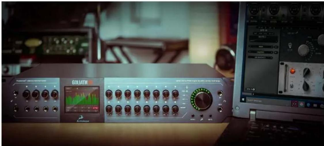
Interior of a recording studio featuring a Goliath audio workstation with multiple instrument panels and a computer monitor displaying audio equipment (no readable text or symbols on main components)Despite the unit's extensive touchscreen functionality and formidable array of front panel controls, the software Control Panel is the ultimate "mediator" between the Goliath HD | Gen. 3 and Pro Tools or your preferred DAW. To take complete advantage of the unit's capabilities, you are meant to handle tasks like gain adjustments, signal routing, effects processing, initial mixing and metering from its intuitive, single-window environment. The resulting audio is routed into your DAW for recording in formats of your choice, such as multi-track, stem, and two-channel stereo.
Thus, we encourage you to familiarize yourself with the 'Software Control Panel' chapter - particularly the 'Routing' and HDX' tabs - before you begin working. Several 'Quick Start' examples are provided as well. This way, you can overcome common stumbling blocks for users new to Antelope Audio products and learn how the device integrates with Pro Tools.
To make streaming up to 64 channels of sample-accurate audio into Pro Tools Ultimate possible, the Goliath HD | Gen. 3 is treated as a pair of 32-channel HDX devices. You can configure both from the 'HDX' tab in the software Control Panel. Note that HDX functionality is an optional paid upgrade which is acquired here.
The 'Guitar Amps & Cabs' chapter will show you how to put the Goliath HD | Gen. 3's total of 8 Hi-Z instrument inputs to good use.
The 'Edge & Verge Mic Emulations' chapter is a mandatory read if you want to enjoy the included Edge Duo modeling microphone - a compliment from Antelope Audio - to the fullest.
There is certainly lots to discover about the Goliath HD | Gen. 3. Should you ever find yourself struggling, do not hesitate to contact our Customer Support team over phone, live chat and our ticket system. You can also visit Antelope Audio on YouTube and explore our video tutorials or join the Antelope Audio Users Facebook group and ask for advice. The Knowledge Base is also a valuable source of information.
Best wishes,
Team Antelope
SETTING UP
Once the unit has been connected to an AC power source (95 - 245 V):
- Connect the Goliath HD | Gen. 3 to your Windows or Mac computer with an USB 3 Type-B cable and/or Thunderbolt™ 2 cable. For Pro Tools Ultimate, connect to your HDX card with DigiLink Mini cables and keep the USB and/or Thunderbolt™ connections.
Notes:
- An USB 3 Type-B cable is included. Thunderbolt™ and DigiLink Mini cables are not included.
- The USB and/or Thunderbolt™ connections are required to have the unit recognized by the Antelope Launcher and Control Panel applications. You can keep both and switch them on-the-fly from 'Comms. Interface' in the touchscreen 'MENU'.
- The unit will automatically detect the connection type upon the initial startup, but not on subsequent starts. Manually set the connection type from 'Comms. Interface' in the touchscreen 'MENU' every time you switch between Thunderbolt™ and USB connections.
-
Thunderbolt™ 3 connection requires a third-party TB3 to Legacy TB adapter and corresponding cables.
-
Visit www.antelopeaudio.com and log-in or create a customer account (if you don't have one).
-
Head to the Goliath HD | Gen. 3 'Download' page to get the latest Antelope Launcher and Unified Driver for your operating system (Windows 10 / macOS 10.11 or later). Install the software by following the on-screen instructions.
Note: For Thunderbolt™ connection on Windows, download and install the latest Antelope Audio Windows Thunderbolt™ driver.
- Open Antelope Launcher and make sure your Goliath HD | Gen 3. is running the latest firmware and Control Panel versions.
Note: If your device isn't recognized by Antelope Launcher or the operating system, read this.
- Launch the Goliath HD | Gen 3. Control Panel from the Antelope Launcher.
Note: Bypass any security prompts from your operating system, e.g. Windows Defender Firewall and macOS alerts.
-
Register your device with the 'Antelope Audio Registration Wizard' by following the on-screen instructions.
-
Connect your analog and digital equipment of choice to the Goliath HD | Gen. 3.
-
Launch Pro Tools or your preferred DAW and:
- Choose the Goliath HD | Gen. 3 as your main input and output device.
- Make sure your DAW and operating system sample rates match the device sample rate.
Need any help?
Visit the Antelope Audio Customer Support page, choose your device and go from there.
Configuring for Windows 10
Windows 10 needs a few tweaks to get everything up and running:
- Enter the 'Sounds' options window from the Control Panel or right-click the speaker icon in the system tray and choose 'Sound'.
- Enter the 'Playback' tab and make sure the Goliath HD | Gen. 3 is set as the default playback device. Choose the device and click 'Properties'.
- Enter the 'Supported Formats' tab and place checkmarks next to all the available sample rates.
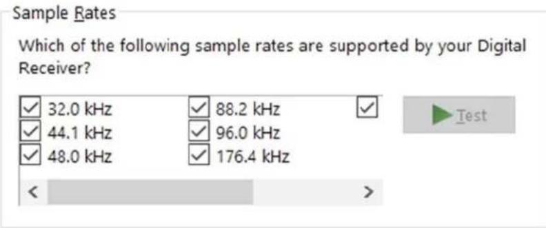
- Enter the 'Enhancements' tab and make sure all enhancements are disabled.
- Enter the 'Advanced' tab and choose any of the available "2 channel, 24-bit" modes. Click 'OK' to close the window.
Default Format
Select the sample rate and bit depth to be used when running in shared mode.
2 channel, 24 bit, 44100 Hz (Studio Quality)

Test
- Enter the 'Recording' tab. Make sure the Goliath HD | Gen. 3 is set as the default recording device and all enhancements are disabled. Click 'OK' to close the window.
Tips
- If you are experiencing interruptions or failure when using your DAW and trying to playback audio from your OS at the same time, make sure that the device sample rate matches the one of your DAW session.
- You can disable the device and enable it again from the 'Playback' tab to refresh the driver. This will be similar to disconnecting and re-connecting your device, which makes Windows reset the playback configuration of the applications you are using.
- In some cases, disabling the 'Exclusive mode' functionality from the 'Advanced' tab in 'Playback' and 'Recording' Properties might help when running multiple playback applications at the same time.
- Disabling the 32kHz sample rate isn't mandatory, but it might help in general.
Further Reading
Antelope Audio Knowledge Base - Windows 10 Optimization
Configuring for macOS 10.14 Mojave (or later)
The new security settings introduced in macOS 10.14 Mojave may result in no input signal reaching your DAW, despite having everything set up correctly.
These steps apply when you are using the Goliath HD | Gen. 3 in a DAW for the first time:
- Launch your DAW and choose Goliath HD | Gen. 3 as the input device. The following dialog box will appear (if using Ableton Live 10 Suite, for example):
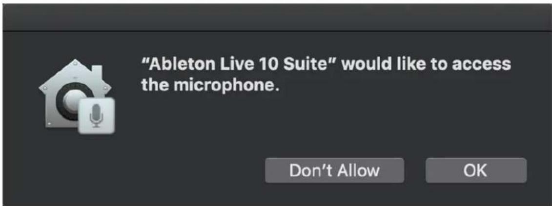
- Click 'OK' and your DAW should function normally.
-
However, if the events above did not occur for some reason, or you are using multiple DAWs, you must do a manual tweak for each in 'Security & Privacy' settings:
-
Click the 'Apple' symbol and choose 'System Preferences'. Head to the 'Security & Privacy' settings menu.
- Click the 'Privacy' tab. In the column on the left, choose 'Microphone'. Make sure there's a checkmark next to any DAW you want to use.
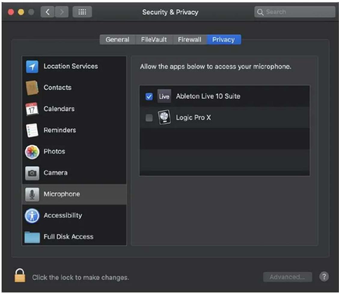
Note: You may have to click the padlock symbol in the bottom left corner and enter your password to make changes.
HDX Activation
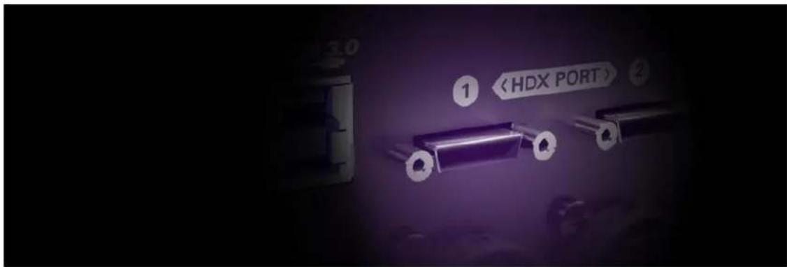
After purchasing HDX Activation you will receive a Claim Code at the e-mail address you used to register your Antelope Audio user account.
Note: If the e-mail doesn't seem to arrive in your inbox, please check your 'Spam' and 'Junk' folders.
- Log-in to antelopeaudio.com and head to the 'Claim Features' page to enter your Claim Code.
- Open Antelope Launcher and launch the Goliath HD | Gen. 3 Control Panel application.
- Click the '?' button, then click 'ADMINISTRATION'. This will launch the 'Antelope Registration Wizard'. Log-in with your Antelope Audio account information and click 'Continue'.
- Choose 'Register device or assign features' and click 'Continue'. Follow the on-screen instructions to assign HDX Activation to your Goliath HD | Gen. 3. After successful activation, the 'HDX NOT ENABLED' message will disappear from the 'HDX' tab in the Control Panel.
Need any help?
Visit the Antelope Audio Customer Support page, choose your device and go from there.
FRONT PANEL EXPLAINED

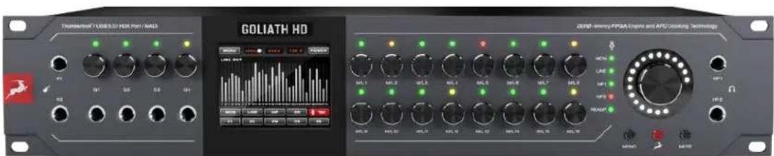
Left to right, top to bottom:
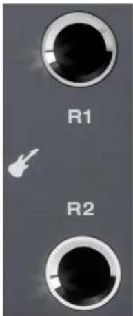
1. REAMP Outputs 'R1' - 'R2'
Instrument-level outputs on 1/4-inch TS mono jacks. Designed for use with guitar amplifiers and other equipment suitable for re-amping DI tracks. Read '6.6.4. Re-amping' to learn more about re-amping.
Note: You can use the REAMP outputs as Sends for external equipment, such as hardware processors and effects, though this is 'off label' and results may vary. Audio is output at instrument-level, which is significantly quieter than line-level and typically requires a preamp for an recommend using the insert points on the rear panel for Send/Return co instead.
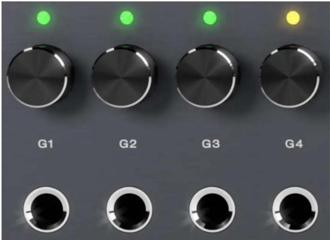
2. Hi-Z instrument inputs 'G1' - 'G4' with Gain Control Knobs and LED Indicators
Four Hi-Z inputs on 1/4-inch TS mono jacks for connecting high-impedance instruments, such as electric guitar and bass.
• Use regular 1/4-inch TS instrument cables.
- LEDs above each knob indicate incoming signal strength with colors. 'Green' might be too weak. 'Yellow' is mostly okay. Avoid 'Red'!
- Turn the knob above each input to adjust gain (-10dB to 40dB).
- Press the knob to view the current gain adjustment without changing it.
• . Press-and hold the knob to mute
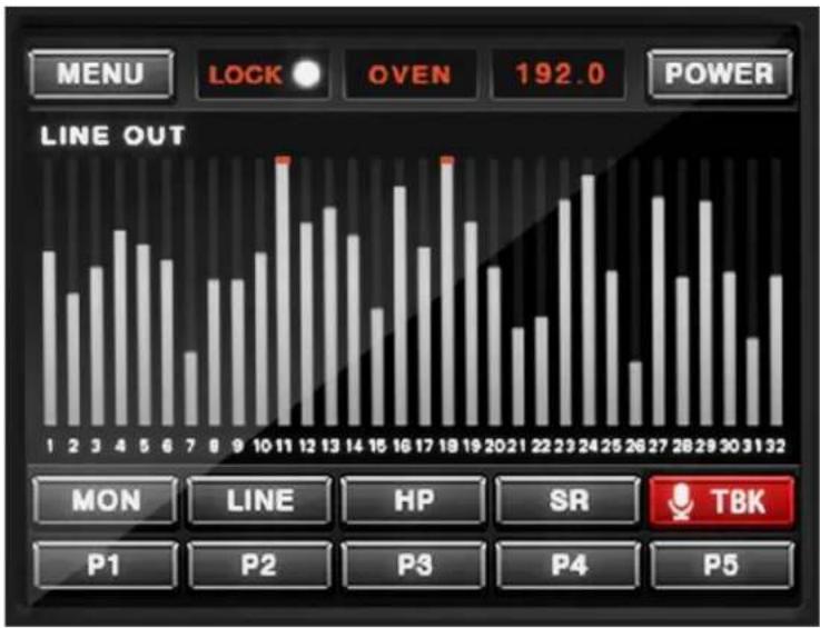
3. Touch Screen
The front panel's centerpiece. Basic functionality explained (left to right, top to bottom):
- 'MENU' - Tap to enter the Goliath HD | Gen. 3 System Menu.
- 'Lock' - Lights up when the Goliath HD | Gen. 3 is locked to another audio device (e.g. ADAT).
- 'OVEN' - Shows the current clock source. Tap to change.
- '192.0' - Shows the device sample rate. Tap to change.
- 'POWER' - Tap to power off the unit. Tap again to confirm.
- Peak Meters - Visualise audio levels for the chosen audio source. Tap anywhere to choose the audio source. Up to 32 audio channels are shown at once.
- 'MON' - Tap to view and adjust monitor output volume. Use the touchscreen or main rotary control.
- 'LINE' - Tap to view and adjust line output volume. Use the touchscreen or main rotary control.
- 'HP' - Tap (and keep tapping) to view and adjust headphone output volume. Use the touchscreen or main rotary control.
- 'SR' - Tap (and keep tapping) to view and adjust instrument and mic/line inputs volume. Use the touchscreen or main rotary control.
- 'TBK' - Tap to view and adjust Talkback microphone input source, input gain, and output assignments.
• 'P1' - 'P5' - Tap to recall presets 1 - 5.
bar
| Day | Line Out | |---|---| | 1 | 85 | | 2 | 60 | | 3 | 75 | | 4 | 90 | | 5 | 80 | | 6 | 70 | | 7 | 40 | | 8 | 65 | | 9 | 65 | | 10 | 75 | | 11 | 100 | | 12 | 80 | | 13 | 90 | | 14 | 75 | | 15 | 50 | | 16 | 100 | | 17 | 80 | | 18 | 100 | | 19 | 90 | | 20 | 75 | | 21 | 55 | | 22 | 60 | | 23 | 95 | | 24 | 105 | | 25 | 70 | | 26 | 35 | | 27 | 100 | | 28 | 80 | | 29 | 95 | | 30 | 75 | | 31 | 60 | | 32 | 80 |The touchscreen is covered in more detail in '5. Touchscreen Functionality'.
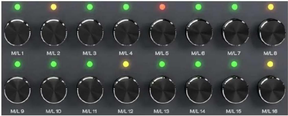
4. Mic/Line Inputs 1 - 16 Gain Control Knobs with LED Indicators
16 gain control knobs for M/L inputs 1 - 16 with LED indicators and push functionality.
- LEDs above each knob indicate incoming signal strength with colors. 'Green' might be too weak. 'Yellow' is mostly okay. Avoid 'Red'!
- Turn the knob above each label to adjust gain for the corresponding input. Gain ranges: 0dB - 65dB (Mic) / -6dB - 20dB (Line).
- Press the knob once to view the current gain adjustment without changing it.
- Keep pressing the knob to change between Mic or Line input signal type. Inputs 1 - 4 also have Hi-Z.
- Press-and-hold the knob to mute.
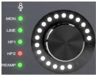
5. Main Rotary Control Knob with LED Indicators and LED Ring
Large rotary control knob with LED indicators indicating mute status for the chosen output and LED Ring indicating the volume level.

- 'Green' light means un-muted. 'Red' light means muted.
- Press (and keep pressing) the knob to cycle through the available outputs.
- Turn to adjust volume for the chosen output.
- Use the knob in combination with the three buttons below:
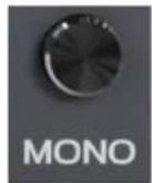
Mono Button
For MON/HP1/HP2 outputs - press once to downmix to mono. Press again to return to stereo.
Antelope Button
Function key with the following functionality:
- Press-and-hold Antelope button + Main Rotary Control Knob to access diagnostic tests. Useful when troubleshooting and contacting Customer Support.
- Press-and-hold Antelope button + Mono Button to enter touchscreen calibration. Use this if experiencing problems with touch input recognition due to a mis-calibrated screen.
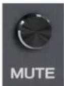
Mute Button
Press to mute the currently chosen output. Press again to un-mute.
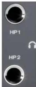
Headphone outputs 'HP1' - 'HP2'
2x stereo headphone outputs on 1/4-inch TRS jacks.
REAR PANEL EXPLAINED
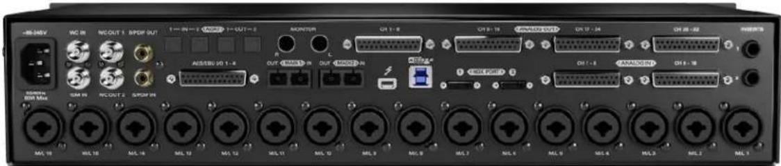
Left to right, top to bottom:
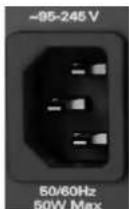
1. Mains Power Connection
The IEC connector supports a range from \~95-245 V. The device automatically accommodates mains voltage in every country.
2. Word Clock Input (Top)
BNC connector to accept Word Clock reference signal from another device using a standard BNC cable.
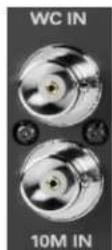
3. 10M Input (Bottom)
This BNC connector lets the Goliath HD | Gen. 3 receive timing reference from an Antelope Audio Atomic Master Clock, such as the 10M and 10MX, thereby increasing oscillator accuracy, musical detail, and clock stability. Click here to learn more.
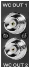
4. Word Clock Outputs
BNC connectors to output Word Clock reference signal using standard BNC cables.
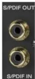
5. S/PDIF I/O
75ohm S/PDIF connectors for use with compatible equipment over coaxial RCA cables.
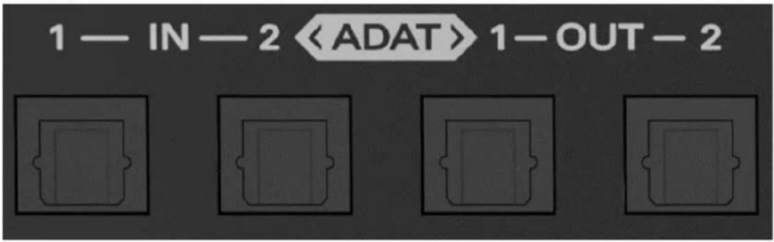
6. ADAT I/O
2 inputs and 2 outputs carrying up to 16 I/O audio channels over Toslink fiber optic cables. Standard ADAT audio limits apply:
• Up to 16 I/O channels of 24-bit, 48kHz audio.
- Up to 8 I/O channels of 24-bit, 96kHz audio (over S/MUX).
- Up to 4 I/O channels of 24-bit, 192kHz audio (over S/MUX).
• All ADAT audio is transmitted in 24-bit resolution.
Note: Devices do not need to be powered off for connecting or disconnecting ADAT. However, you should mute the receiving equipment because a large signal spike will occur upon connecting.
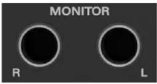
7. L/R Monitor Outs
1/4-inch signal-balanced TS/TRS monitor outs boasting the highest dynamic range in the system.
8. D-SUB 25-pin Line Outputs
Four DB-25 breakout cable connectors carrying 8 audio channels each (32 channels in total). Compatible with TASCAM Standard Pin Layout.

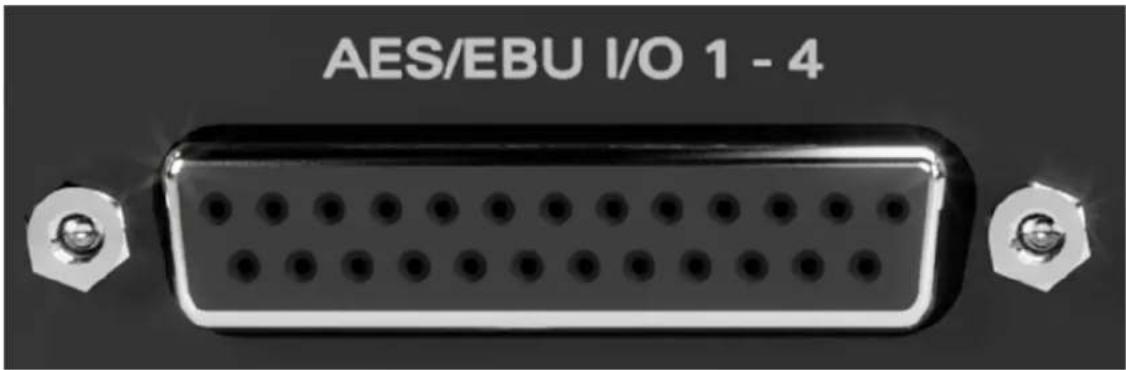
9. AES/EBU I/O
• 4x AES/EBU In on DB-25 (8 channels)
• 4x AES/EBU Out on DB-25 (8 channels)
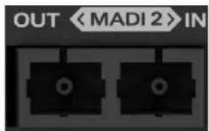
10. MADI 1 - 2 I/O
MADI I/O carrying up to 128 I/O channels total over fiber optic cables with SC-Plugs on both ends. Standard MADI audio limits apply per connector:
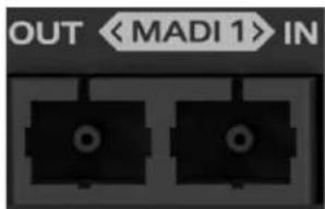
• Up to 64 I/O channels of 24-bit, 48kHz audio.
• Up to 32 I/O channels of 24-bit, 96kHz audio.
• Up to 16 I/O channels of 24-bit, 192kHz audio.
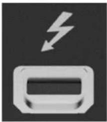
11. Thunderbolt™ 2 Port
Thunderbolt™ 2 computer connection. Supports up to 64 I/O audio channels at sample rates up to 192kHz.
Note: Thunderbolt™ 3 connection requires a third-party TB3 to Legacy TB adapter and corresponding cables.
natural_image
Icon of a battery with a lightning bolt symbol (no text or numbers)
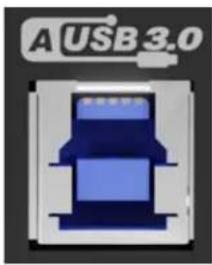
12. USB 3 Type-B Port
USB 3 computer connection. Supports up to 64 I/O audio channels at sample rates up to 192kHz.
Note: USB 2 connection is limited to 8 I/O audio channels.
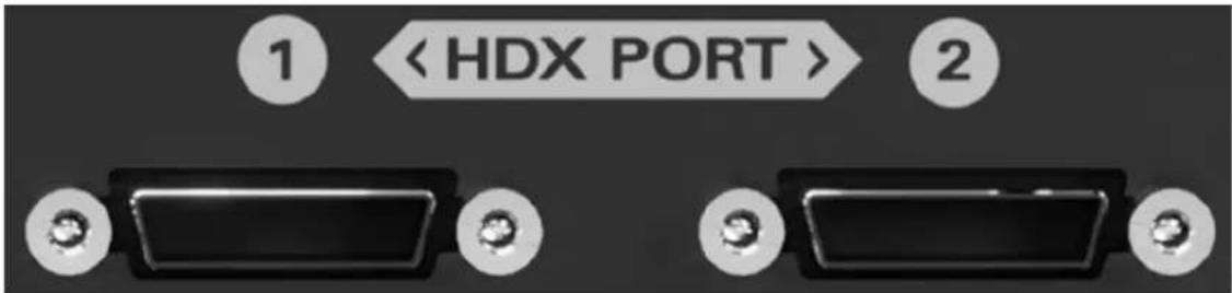
13. HDX Ports
Connect the Goliath HD | Gen. 3 to a Pro Tools HDX system with DigiLink Mini cables (not included). Up to 32 I/O audio channels are available per port.
14. D-SUB 25-pin Line Inputs
Two DB-25 breakout cable connectors carrying 8 audio channels each (16 channels in total). Compatible with TASCAM Standard Pin Layout.

15. AD Inserts 1 - 2
Two 1/4-inch TRS inserts for integrating external analog equipment, such as dynamics processors and EQs.
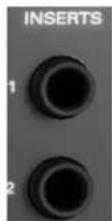
Integrating External Analog Equipment
Each insert is both an analog input and an output, enabling Send/Return functionality from a single jack. The inserts are non-routable, hence they aren't visible in the Routing Matrix. Insert 1 input is hard-wired to 'M/L 1' and Insert 2 input is hard-wired to 'M/L 2'. Both M/L inputs are found on the rear panel.
Workflow
Incoming analog audio from M/L inputs 1 and 2 is automatically routed and processed through your external equipment before it's fed back into the interface to hit the A/D converters. This is accomplished via stereo Y-cables (L/R 1/4-inch TS connectors on one end, stereo 1/4-inch TRS connector on the other end). The L/R 1/4-inch TS connectors hook to your equipment's input and output connections, the stereo 1/4-inch TRS connector connects to the AD Insert.
Note: An active audio source must be connected to 'M/L 1' and/or 'M/L 2' for the AD Inserts to function.
1. Mic/Line Inputs 1 - 16
16 analog inputs on combo XLR jacks, switchable between microphone and line-level input. M/L 1 - 4 also offer Hi-Z instrument input.
Important! Record line-level sources using 1/4-inch TS/TRS cables, period.

natural_image
Row of identical black circular buttons labeled ML 10 to ML 7, arranged horizontally (no additional text or symbols)TOUCHSCREEN FUNCTIONALITY
The touchscreen works with single finger taps. Other traditional gestures, such as pinch-to-zoom, multi-touch and so on are not supported.
Feel free to use the included stylus to keep the screen from smudging.
By default, the screen shows up to 32 peak meters for each channel of the chosen audio source. Tap anywhere to change the audio source. The choices are explained in '6.4.1.
Routing tab - Terminology'.
The following functionality is available in addition to what's covered in '3. Front Panel Explained'.
'MENU' Button
Tap 'MENU' to access the System Menu with the following options:
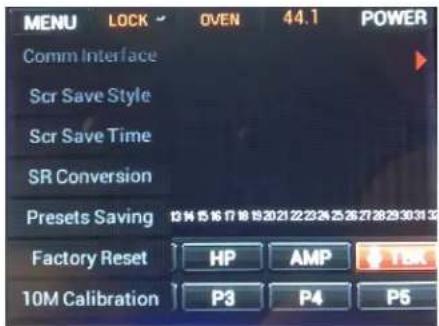
1. Comm. Interface
Tap to choose between Thunderbolt™ and USB connectivity. Make sure your choice matches your computer connection. Note that it is possible to switch connections without powering off or disconnecting the unit:

- If the interface is currently connected over USB but you want to switch to Thunderbolt™: with the interface powered on and still connected over USB, make the Thunderbolt™ connection and choose Thunderbolt™ in this menu.
- If the interface is currently connected over Thunderbolt™ but you want to switch to USB: with the interface powered on and still connected over Thunderbolt™, make the USB connection and choose Thunderbolt™ in this menu.
- If you have to switch often, you can keep both connections and switch on-the-fly from this menu.
2. Scr Save Time
Tap to choose how long it takes for the screensaver to appear.
3. Scr Save Style
Tap to choose the screensaver style.
Note: Overlooking the screensaver options may result in screen burn-in if the unit operates for longer durations regularly. We recommend setting up 'Scr Save Time' to the shortest time period you are comfortable with, and 'Scr Save Style' to 'Black Scr.'. This effectively makes the display turn itself off after a short period of inactivity, which helps prevent burn-in. Press any button or tap the screen to exit the screensaver.
4. SR Conversion
Tap to enable/disable S/PDIF sample rate conversion. For example, if your S/PDIF source is outputting 44.1kHz audio and the Orion 32 HD | Gen. 3 is set to 96kHz, the S/PDIF audio will be sample rate-converted to 96kHz.
5. Presets Saving
Tap to save the current device and session settings into one of the 5 available preset slots. Tap 'P1' - 'P5' (bottom row) to recall presets 1 - 5.
6. Factory Reset
Tap to perform a factory reset of the unit. Tap again to confirm.
Note: All presets, mixer and FX settings will be lost after factory reset.
7. 10M Calibration
Tap to calibrate an Antelope Audio 10M/10MX Atomic Master Clock.
Tap, hold and drag upwards to scroll down to the rest of the menu.
8. Device Info
Shows serial number, hardware revision and software revision information. Useful for troubleshooting.
9. Touch Scr Calibr
Tap to enter touchscreen calibration.
Note: If you experience any issues with touch input recognition, hold the 'Antelope
Button' + 'Mono Button' on the front panel to enter touchscreen calibration. Follow the steps and the display should resume normal operation after calibration.
10. Loop Sync Mode
Tap to turn Loop Sync on or off.
11. LS Input
Tap to choose external Loop Sync source - Word Clock Input or Atomic Clock Input.
12. LS Output
Tap to choose which Word Clock Output you want to use to output timing reference signal - 'WC 1' or 'WC 2'.
Clock Source
Tap 'OVEN' (the third button from left to right, top-most section) to choose the clock source. The following choices are available:
• 'OVEN' - Oven-Controlled Crystal Oscillator (internal)
• 'W.C.' - Word Clock input (external)
• 'S/PDIF' input (external)
- 'AES' input (external)
• ADAT(2x, 4x) input (external)
• MADI 1 - 2 (2x, 4x) input (external)
• 'HDX' - Clock from Pro Tools
- 'USB' - In 'USB' mode the unit still uses its internal clock.
Additional Functionality
- Tap 'POWER' to power off the Goliath HD | Gen. 3. Tap again to confirm.
- The 'LOCK' indicator (immediately before 'OVEN') indicates when the Goliath HD | Gen. 3 is locked to an external device (e.g. ADAT).
- Tap the Sample Rate indicator (immediately after 'OVEN') to change the device sample rate. Please make sure your choice matches the DAW and operating system sample rates.
'MON' Button
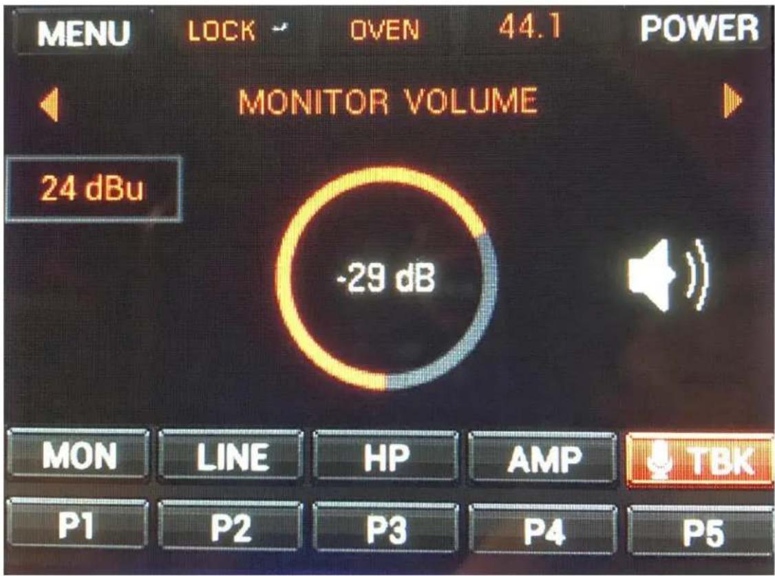
Tap 'MON' to enter Monitor Volume. The following functionality is available:
- By default, tapping 'MON' enters Monitor Volume.
- Tap the left and right arrows to 'cycle' the analog outputs. This is the same as pressing the main rotary control knob.
- Tap '24 dBu' to adjust signal trim in preset dBu values.
- Tap, hold and drag the circle to adjust volume in dB. You can also do this from the main rotary control knob.
- Tap the 'Speaker' symbol to mute or un-mute the outputs.
- Tapping 'LINE' or 'HP' takes you to the 'Line Out Volume' and 'HP1/HP2 Volume' pages, respectively. The functionality is identical.
'AMP' Button

- Tap 'AMP' to access gain controls for M/L inputs 1 - 16 and Hi-Z instrument inputs 'G1' - 'G4'.
You can also turn any of the 20 gain control knobs on the front panel and you will enter this view.
- Tap the left and right arrows to cycle the inputs.
- Tap 'Mic' to choose the input signal type:
- Mic (microphone input)
- Line (line-level input)
- Hi-Z (high-impedance instrument input, available on M/L inputs 1 - 4.)
- Tap, hold and drag the circle to adjust volume in dB. You can also do this from the gain control knobs.
- Tap the 'Speaker' symbol to mute or un-mute the input.
'TBK' Button
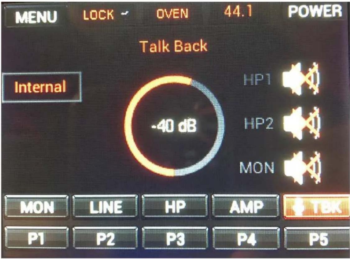
Tap 'TBK' to enter Talk Back. The following functionality is available:
- Tap 'Internal' to change the Talkback microphone input from the built-in mic ('Internal') to any microphone connected to M/L inputs 1 - 16.
- Tap, hold and drag the circle to adjust volume in dB. You can also do this from the main rotary control knob.
- Tap 'HP1' to route Talkback input to Headphone output 1 (HP1). Tap again to undo.
- Tap 'HP2' to route Talkback input to Headphone output 2 (HP2). Tap again to undo.
- Tap 'MON' to route Talkback input to main monitor outputs. Tap again to undo.
Note: You can route Talkback input anywhere for monitoring and recording purposes from the Routing Matrix.
'P1' - 'P2' Buttons

Tap any of these buttons to recall presets 1 - 5.
SOFTWARE CONTROL PANEL
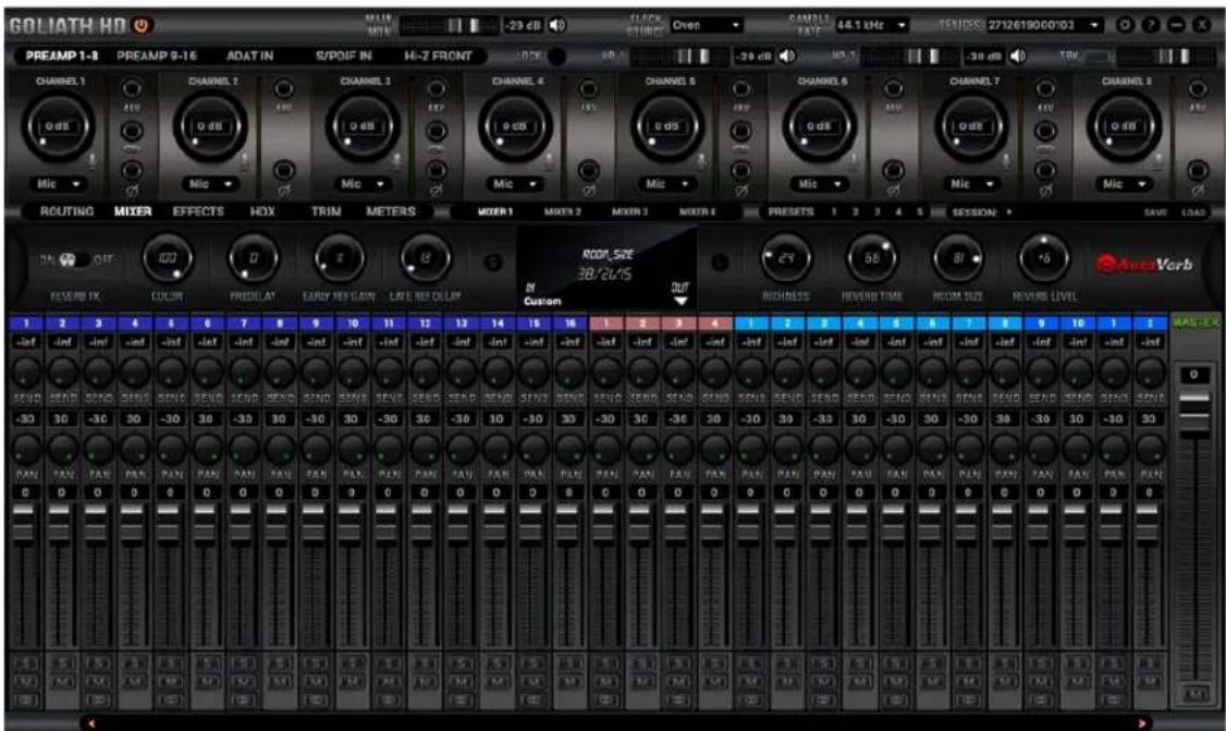
Welcome to the Goliath HD | Gen. 3 Core software Control Panel! More than just an alternative to the physical front panel controls, it provides intuitive and comprehensive access to each aspect of the interface's functionality. This includes settings, signal routing, audio mixing, effects stacking, metering, HDX-specific functionality, signal trimming, presets and more.
Quick Start
Let's begin with some quick examples of essential tasks being accomplished in the Control Panel.
Note: These examples do not convey the "correct" or "only" way of accomplishing the following tasks. They merely illustrate some fundamental logic and offer solutions to the initial stumbling blocks most often encountered by novice users.
1. Monitor incoming audio via headphones
Say you want to monitor incoming audio from preamp/line input 1 via headphones hooked to HP1 on the front panel. Open the Control Panel and enter the 'Routing tab'. Drag the colored number block labeled 'PREAMP' 1 onto the pair of blocks labeled 'HP1'. Do this for both blocks if you want to listen from both sides. Adjust preamp and headphone gain from the Control Panel or the interface's front panel controls.
FROM:


2. Apply FPGA FX to incoming audio
Say you want to run audio from preamp/combo input 1 through a custom FX chain while monitoring the result through your studio monitors hooked to the Main Monitor outputs. Open the Control Panel and enter the 'Routing' tab. Drag the colored block numbered 1 from the row labeled 'PREAMP' onto the colored block numbered 1 in the row labeled 'AFX IN'.
FROM:

TO:

Next, drag the colored block numbered 1 from the row labeled 'AFX OUT' onto the pair of blocks labeled 'MAIN MONITOR'. Do this for each block if you want output from both speakers.
FROM:

TO:

Now, click the 'Effects' tab. Add your choice FX by clicking the 'ADD NEW EFFECT' drop-down menu. Listen to your FX-processed audio and play around with the FX parameters.
3. Play guitar through the virtual amps and cabinets, listening from studio monitors
Connect your studio monitors to the Monitor L/R outputs on the interface's rear panel. Next, connect your instrument to Input 'G1' on the front panel. Open the Control Panel and have a look at the top section. Click the 'Hi-Z FRONT' tab.

You will notice 4 large knobs labeled 'CHANNEL 1 – 4'. 'CHANNEL 1' is your guy. Adjust gain by playing guitar while clicking and dragging the knob. Yes, it's possible with just one pair of hands. Yes, it's awkward.
Note: Be careful not to run the input into the red with too much gain. Ideally, your strongest picking or strumming should cause the meter to run into the yellow. Now that we've gone through all that hard work called 'gain calibration', let's sort out signal routing. Enter the 'Routing' tab. Drag the colored block numbered 1 from the row labeled 'INSTRUMENT' onto the colored block numbered 1 in the row labeled 'AFX IN'.
FROM: INSTRUMENT 1 TO: AFX IN 1
Drag the colored block numbered 1 from the row labeled 'AFX OUT' onto the pair of blocks labeled 'MAIN MONITOR'.
FROM: AFX OUT 1 TO: MAIN MONITOR 1 2
Finally, head to the 'Effects' tab. Click the 'ADD NEW EFFECT' drop-down menu and come up with some amp and cabinet combinations. Adjust the FX parameters, listen to the different amp and cabinet models, and have fun!
4. Sing with microphone emulations and monitor live with headphones
Connect your headphones to HP1 on the front panel. Connect your complimentary Antelope Audio Edge Duo modeling microphone to M/L inputs 1 - 2 on the rear panel. Open the Control Panel and enter the 'Routing' tab. Drag blocks 1 and 2 from the row labeled 'EMU MIC' onto the pair of blocks labeled 'HP1'. Do this for both blocks if you want to monitor from both sides.


Enter the 'PREAMPS 1-8' tab. Choose 'Mic' from the drop-down menu and activate 48V phantom power for 'CHANNEL 1'. Click the 'Link' button next. Use the Control Panel software or front panel controls to adjust microphone preamp gain and headphone
output volume. Enter the 'PREAMPS 1-8' tab on 'CHANNEL 1'. It looks like this:
again and click the 'Mic' symbol
This opens the 'Mic Emulations' window. Click and turn the dial to select the emulations available for Edge Duo. You should be hearing your voice in your headphones in real-time, with mic emulations applied. Have fun!
5. Route audio to your DAW for recording
Any audio source listed in the Control Panel 'Routing' tab can reach your DAW by dragging its colored number block(s) onto any of the blocks labeled 'TB REC' (on Thunderbolt™ connection), 'USB REC' (on USB connection) and 'HDX REC' (for Pro Tools HDX).
The 'REC' blocks mirror the inputs recognized by your DAW - e.g. 'TB REC 1 - 32' (or 'USB REC 1 - 32') = DAW 'Inputs 1 - 32' and 'HDX REC 1' = Pro Tools 'Inputs 1 - 32'. Or, to put it another way:
DAW Inputs 1 - 64 (Thunderbolt™):
| TB REC 1-32* | 1 | 2 | 3 | 4 | 5 | 6 | 7 | 8 | 9 | 10 | 11 | 12 | 13 | 14 | 15 | 16 | 1 | 2 | 3 | 4 | 5 | 6 | 7 | 8 | 9 | 10 | 11 | 12 | 13 | 14 | 15 | 16 |
| TB REC 33-64* | 1 | 2 | 3 | 4 | 5 | 6 | 7 | 8 | 9 | 10 | 11 | 12 | 13 | 14 | 15 | 16 | 1 | 2 | 3 | 4 | 5 | 6 | 7 | 8 | 9 | 10 | 11 | 12 | 13 | 14 | 15 | 16 |
DAW Inputs 1 - 64 (USB 3):
| USB REC | 1 | 2 | 3 | 4 | 5 | 6 | 7 | 8 | 9 | 10 | 11 | 12 | 13 | 14 | 15 | 16 | 17 | 18 | 19 | 20 | 21 | 22 | 23 | 24 | 25 | 26 | 27 | 28 | 29 | 30 | 31 | 32 |
| USB REC2 | 33 | 34 | 35 | 36 | 37 | 38 | 39 | 40 | 41 | 42 | 43 | 44 | 45 | 46 | 47 | 48 | 49 | 50 | 51 | 52 | 53 | 54 | 55 | 56 | 57 | 58 | 59 | 60 | 61 | 62 | 63 | 64 |
Pro Tools Inputs 1 - 64 (HDX):
| HDX REC 1-32 | 1 | 2 | 3 | 4 | 5 | 6 | 7 | 8 | 9 | 10 | 11 | 12 | 13 | 14 | 15 | 16 | 17 | 18 | 19 | 20 | 21 | 22 | 23 | 24 | 25 | 26 | 27 | 28 | 29 | 30 | 31 | 32 |
| HDX REC 33-64 | 33 | 34 | 35 | 36 | 37 | 38 | 39 | 40 | 41 | 42 | 43 | 44 | 45 | 46 | 47 | 48 | 49 | 50 | 51 | 52 | 53 | 54 | 55 | 56 | 57 | 58 | 59 | 60 | 61 | 62 | 63 | 64 |
This way, you can record 'dry' and FX-processed audio on different tracks simultaneously, output up to four separate mixes in multi-track or 2-channel stereo formats, and monitor everything from the Control Panel application with the lowest possible latency.
Mouse & Keyboard Shortcuts
The following features are accessible via mouse & keyboard shortcuts in the Control Panel:
- Return to unity gain (all knobs and faders): double-click the knob or fader.
- Click any peak meter to reset it.
- Change text labels and manually enter gain values: double-click the text label / gain value.
- Adjust parameters in 1-step increments (all knobs and faders): Ctrl-click (Windows) / Command-click (macOS) and drag.
- Detach, move and resize Control Panel tabs: Right-click (Windows) / Command-click (macOS) and drag the relevant tab.
- Save Preset 1–5: Ctrl-click (Windows) / Command-click (macOS) on Presets 1–5.
Main View

The Main View is always visible in the Control Panel's top section. It's organized as follows:
1. Function Strip 1

From left to right:
On/Off Button
On/Off button for the hardware unit.
Monitor Volume
Monitor volume fader. Click the 'Speaker' symbol to mute or un-mute.

Clock Source
Click the drop-down menu to choose the clock source. The following options are available:
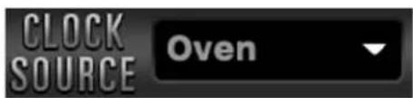
- 'OVEN' - Oven-Controlled Crystal Oscillator (internal)
• 'W.C.' - Word Clock input (external)
• 'S/PDIF' input (external) - 'AES' input (external)
• ADAT(2x, 4x) input (external)
• MADI 1 - 2 (2x, 4x) input (external)
• 'HDX' - Clock from Pro Tools
- 'USB' - In 'USB' mode the unit still uses its internal clock.
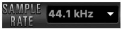
Sample Rate
Click the drop-down menu to choose the device sample rate. Please make sure your choice matches the DAW and operating system sample rates.
Devices
Drop-down menu listing connected Antelope Audio devices by their serial number.

Note: You are expected to run a separate Control Panel instance for each connected device you want to use in your session. Each Control Panel has its own settings (routing, etc.). While it's possible to switch devices from the drop-down menu on the fly, you may find this workflow less convenient.
Settings Button
Click to open the 'Settings' window.

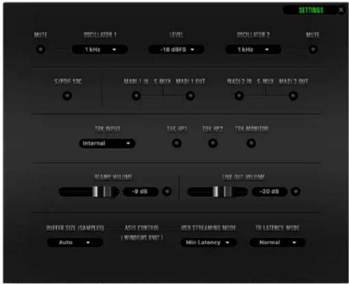
From left to right, top to bottom:
MUTE
Click to mute Oscillator 1 output.
OSCILLATOR 1
Choose a frequency for the Oscillator 1 test signal from the drop-down menu.
LEVEL
Choose the output level (in dBFS) for the oscillator 1 & 2 test signals.
OSCILLATOR 2
Choose a frequency for the Oscillator 2 test signal from the drop-down menu.
MUTE
Click to mute Oscillator 2 output.
SRC
Click to enable or disable S/PDIF sample rate conversion. For example, if your S/PDIF source is outputting 44.1kHz audio and the Goliath HD | Gen. 3 is set to 96kHz, the S/PDIF audio will be sample rate-converted to 96kHz.
MADI 1 IN/OUT & S-MUX
Enable or disable MADI 1 I/O (channels 1 - 64). S/MUX is enabled and disabled automatically.
MADI 2 IN/OUT & S-MUX
Enable or disable MADI 1 I/O (channels 65 - 128). S/MUX is enabled and disabled automatically.
TBK INPUT
Click to change the Talkback microphone input from 'Internal' (the built-in mic) to any microphone connected to M/L inputs 1 - 16.
TBK HP1
Click to route Talkback microphone input to Headphone output 1 (HP1).
TBK HP2
Click to route Talkback microphone input to Headphone output 2 (HP2).
TBK MONITOR
Click to route Talkback microphone input to Main Monitor output.
REAMP VOLUME
Adjust REAMP outputs volume (in dB). Click the circle to enable or disable the outputs.
LINE OUT VOLUME
Adjust line outputs volume (in dB). Click the circle to enable or disable the outputs.
BUFFER SIZE (SAMPLES)
Choose the ASIO buffer size from the drop-down menu.
USB STREAMING MODE
Choose the USB streaming mode from the drop-down menu. Experiment with the different modes if you experience audio glitches, CPU overload, etc.
TB LATENCY MODE
Choose the Thunderbolt Latency mode from the drop-down menu. Experiment with the different modes if you experience audio glitches, CPU overload, etc.
Note: 'BUFFER SIZE (SAMPLES)' and 'USB STREAMING MODE' are exclusive to Windows users connected over USB.
Back to Function Strip 1...
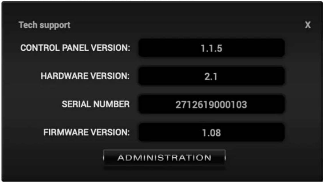
Help Button
Click to open the 'Help' window. There, you can contact Tech Support, view technical information (useful for troubleshooting), and click the 'ADMINISTRATION' button to launch the 'Antelope Registration Wizard'.

Minimize Button
Click to minimize the Control Panel application.

Close Button
Click to close the Control Panel application.

2. Function Strip 2

From left to right:
Input Gain Tabs

Tabs containing gain controls for analog and digital audio inputs. The functionality is explained in '6.3.4. Input Gain Tabs'.
Lock Indicator
Lights up when the Goliath HD | Gen. 3 is locked to another device (e.g. ADAT).
HP1 Volume and Mute
Volume fader for Headphone output 1 (HP1). Click the 'Speaker' symbol to mute and un-mute.

HP2 Volume and Mute

Volume fader for Headphone output 2 (HP2). Click the 'Speaker' symbol to mute and un-mute.
TBK Button and Volume
Click to turn Talkback microphone input on or off. The indicator lights up when Talkback is on. Use the fader to adjust gain.

3. Input Gain Tabs
From left to right:
PREAMP 1 - 8 tab

Contains controls for M/L inputs 1 - 8.
PREAMP 9 - 16 tab

Contains controls for M/L inputs 9 - 16. The functionality is explained below:
The controls for M/L inputs 1 - 16 are identical and have the following functionality:
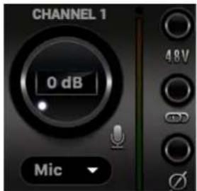
Text Label
Double-click to change the text.
Gain Knob and Mic Emulations Button
Click and drag the knob or double-click its text label (inner center) to adjust input gain. The available gain ranges are:
- Mic: 0dB - 65dB
• Line: -6dB - 20dB
• Hi-Z (Channels 1 - 4): -10dB - 40dB
Click the 'Mic' symbol to open the 'Mic Emulations' window. Head to '6.6.5. Edge & Verge Mic Emulations' to learn more.
CHANNEL 1
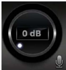
Mic/Line Input Selector
Click to choose the type of audio input:
- Mic (microphone)
• Line (line-level sources)
• Hi-Z (high-impedance instruments, available on Channels 1 - 4).
Input Signal Strength Meter
Visualizes the input signal strength. Running into the red 'clips' the input because of excess input gain. Reduce gain and try again.
Note: Some recordists enjoy the sound of overdriven mic preamps and mixer inputs for vocal and instrument recording. It's safe to give it a try, but don't push too hard.
48V Phantom Power Button
Click to activate or de-activate 48V phantom power for condenser microphones.
Link Button
Available on odd-numbered channels. Click this button to link channels in pairs of two. When channels are linked, any change made to one channel applies the same exact change to its neighboring channel.
Phase Flip Button
Click to flip signal polarity.
ADAT IN tab

This tab contains controls for 16 ADAT digital audio inputs with editable text labels, gain adjustment knobs, Link buttons and signal strength meters. The available input gain range for all channels is -6dB – 12dB. Note that ADAT runs on S/MUX.
S/PDIF IN tab

This tab contains controls for 2 S/PDIF digital audio inputs with editable text labels, gain adjustment knobs, Link buttons and signal meters. The available input gain range for all channels is -6dB – 12dB.
Hi-Z FRONT tab

This tab contains controls for the four Hi-Z high-impedance instrument inputs labeled 'G1' - 'G4' on the front panel. They have editable text labels, gain adjustment knobs, phase flip buttons, Link buttons and signal meters. The available input gain range for all channels is -10dB - 40dB.
4. Tab Selector
Click to switch tabs below the Main View.

5. Presets
The following functionality is available:

- Click a number to load preset 1 - 5.
- Ctrl-click/Command-click a number to store a preset into that slot.
6. Sessions

Drop-down menu with saved SESSIONS and adjacent SAVE/LOAD buttons.
SESSIONS are complete "snapshots" of entire Control Panel configurations.
When Saving a Session, you can choose the exact components you want stored and export Session files for storage and sharing from the 'Save As' button. When loading a Session, you can browse your computer for session files and choose which components to load.
Routing tab
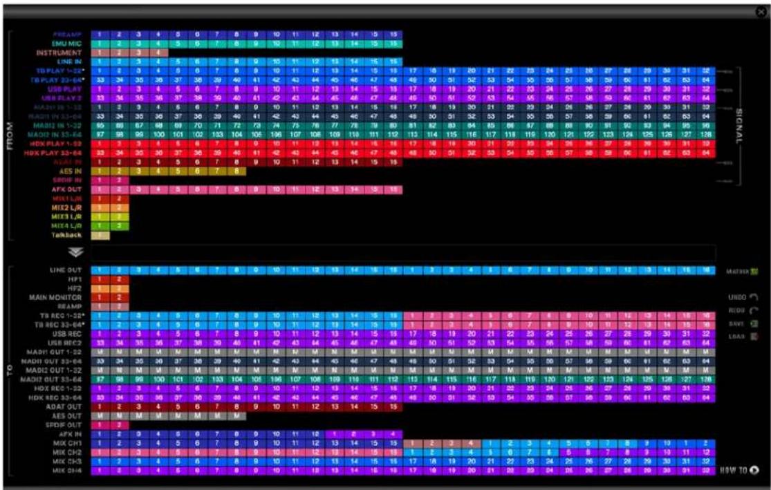
This tab features the Routing Matrix (pictured above) for analog and digital audio routing. It's contained inside a floating window. If you have a multi-screen setup, we recommend leaving it open on a secondary screen for the session.
The Routing Matrix is row-based. Each row has its own unique color and represents a specific audio in or out with its maximum number of channels.
The Routing Matrix is split in two main sections: From (Source) and To (Destination). Route audio between them by dragging and dropping the colored number blocks. The following functionality is also available:
- Click on a number block to highlight the destinations it's currently routed to.
- Double-click a number block to change its text label.
- Right-click (or Command-click) a colored block and choose 'Mute' to mute this channel or 'Mute All' to mute all channels in the row.
- An alternative grid-based view is available (click 'MATRIX'). Please read the guide.
- Undo/Redo buttons are also available.
- Save/Load buttons let you save and load routing configurations (as opposed to entire Sessions).
- The 'How-To' button points your Internet Browser to a YouTube playlist with tutorial videos.
Terminology
From (Source) Section:
PREAMP
This row represents each of the 16 mic/line inputs.
EMU MIC
This row represents mic preamp inputs 1 - 16 with mic emulations applied to incoming microphone audio. This offers some interesting possibilities, such as:
- Simultaneous monitoring and recording of dry microphone audio from the 'PRE-AMP' row and mic emulation audio from the 'EMU MIC' row on separate audio tracks in your DAW – with and without FPGA FX added on top.
- Setting up multiple monitoring mixes, e.g. 'dry' mix for the recording engineer and 'mic emulation' mix for the performing artist, with different FX chains on all mix channels.
More information is available in '6.6.5. Edge & Verge Mic Emulations'.
INSTRUMENT
This row represents the four Hi-Z instrument inputs labeled 'G1' - 'G4' on the front panel.
LINE IN
This row represents 16 line inputs over two D-Sub 25-pin connectors (TASCAM Standard Pin Layout) on the rear panel. Each D-Sub connector provides 8 mono audio channels.
TB PLAY 1 - 32 / 33 - 64
When your interface is connected over Thunderbolt™, the 'TB PLAY' rows represent DAW 'Outputs 1 – 64'. This is where you receive audio from your DAW. Create a new track in your DAW and assign the output with matching number - e.g. DAW 'Output 1' = 'TB PLAY' 1.
Note: These rows also represent all computer audio, such as media playback, YouTube, etc.
USB PLAY & USB PLAY 2
When your interface is connected over USB 3, the 'USB PLAY' rows represent DAW 'Outputs 1–64' (or DAW 'Outputs 1–8' on USB 2). This is where you receive audio from your DAW. Create a new track in your DAW and assign the output with matching number - e.g. DAW 'Output 1' = 'USB PLAY' 1.
Note: These rows also represent all computer audio, such as media playback, YouTube, etc.
MADI1 IN 1 - 32 / 33 - 64
These rows represent MADI Inputs 1 - 64.
MADI2 IN 1 - 32 / 33 - 64
These rows represent MADI Inputs 65 - 128.
HDX PLAY 1 - 32 / 33 - 64
When your interface is connected over HDX, the 'HDX PLAY' rows represent Pro Tools 'Outputs 1 – 32' and 'Outputs 33 – 64'. This is where you receive audio from Pro Tools. Create a new track and assign the output with matching number - e.g. 'Output 1' = 'HDX PLAY' 1.
Note: To make streaming up to 64 channels of sample-accurate audio into Pro Tools Ultimate possible, the Goliath HD | Gen. 3 is treated as a pair of 32-channel HDX devices. You can configure both from the 'HDX' tab.
ADAT IN
This row represents up to 16 ADAT optical audio inputs, found on 2 ports of 8 channels each.
AES IN
This row represents 8 channels of incoming AES/EBU audio.
S/PDIF IN
This row represents 2 channels of incoming stereo S/PDIF audio over coaxial RCA cable.
AFX OUT
The AFX OUT row ('AFX' short for 'Antelope FX') represents up to 16 mono audio channels with FPGA FX applied.
Low Latency Mixer Outputs
The MIX 1 L/R to MIX 4 L/R rows represent the four 2-channel stereo outputs from the four software mixers in the 'Mixer' tab.
TALKBACK
This row represents Talkback microphone input and lets you route it anywhere for monitoring and recording.
To (Destination) section:
LINE OUT
This row represents the 32 line outputs over four D-Sub 25-pin connectors (TASCAM Standard Pin Layout) on the rear panel. Each D-Sub connector provides 8 mono audio channels.
HP1
This row represents Headphone output 1 as two mono (L/R) channels.
HP2
This row represents Headphone output 2 as two mono (L/R) channels.
MAIN MONITOR
This row represents Monitor outputs L/R, found on 1/4-inch TS/TRS connectors on the Goliath HD | Gen. 3 rear panel.
Note: These signal-balanced, mastering-grade outputs boast the highest dynamic range in the system.
REAMP
This row represents the two mono REAMP outputs, used for sending DI audio tracks for re-amping through guitar amplifiers and other suitable equipment. Read '6.6.4. Re-amping' if you want to learn more about reamping.
TB REC 1 - 32 / 33 - 64
When your interface is connected over Thunderbolt™, the 'TB REC' rows represent DAW 'Inputs 1 – 64'. This is where you send audio to your DAW. Create a new track in your DAW and assign the input with matching number - e.g. DAW 'Input 1' = 'TB REC' 1.
USB REC 1 & USB REC 2
When your interface is connected over USB, the 'USB REC' rows represent DAW 'Inputs 1 – 64' (USB 3) or DAW 'Inputs 1 – 8' (USB 2). This is where you send audio to your DAW. Create a new track in your DAW and assign the input with matching number - e.g. DAW 'Input 1' = 'USB REC' 1.
MADI1 OUT 1 - 32 / 33 - 64
These rows represent MADI Outputs 1 - 64.
MADI2 OUT1 - 32 / 33 - 64
These rows represent MADI Outputs 65 - 128.
HDX REC 1 - 32 / 33 - 64
When your interface is connected over HDX, the 'HDX REC' rows represent Pro Tools 'Inputs 1 – 32' and 'Inputs 33 – 64'. This is where you send audio to Pro Tools. Create a new track and assign the input with the matching number - e.g. 'Input 1' = 'HDX REC' 1.
Note: To make streaming up to 64 channels of sample-accurate audio into Pro Tools HDX possible, the Goliath HD | Gen. 3 is treated as a pair of 32-channel HDX devices. You can configure both from the 'HDX' tab.
ADAT OUT
This row lets you route up to 16 mono audio channels to the ADAT outputs (2 ports of 8 mono audio channels each). Note that ADAT runs on S/MUX.
AES OUT
This row represents 8 channels of outgoing AES/EBU audio.
S/PDIF OUT
This row lets you send 2 audio channels to S/PDIF-compliant equipment over coaxial RCA cable.
AFX IN
The AFX IN row ('AFX' short for 'Antelope FX') lets you route up to 16 mono audio channels into the FPGA FX.
Note: You must route at least one signal here before any FX are being applied.
MIX CH1 - CH4
The 'Mixer' tab is home to four low-latency mixers with 32 inputs each. This row lets you route audio to their inputs.
If you ever find yourself struggling with the Routing Matrix for some reason, do not hesitate to contact our Customer Support team over phone, live chat and our ticket system. You can also visit Antelope Audio on YouTube and explore our video tutorials, or join the Antelope Audio Users Facebook group and ask for advice.
Mixer tab
The Mixer tab is home to four 32-channel virtual mixers. Each channel is equipped with Pan, Volume, Solo, and Link controls (on odd-numbered channels), as well as metering. The Master channel has Volume and Mute controls.
Limitations
- There is no grouping/bus/sub-mixing functionality, but the four full-fledged mixers give plenty of space to set up sub-mixes (e.g. drum bus, artist headphones) alongside your main mix.

- Due to technical reasons, we cannot offer volume automation inside the mixers at this time.
• MIDI control is not supported.
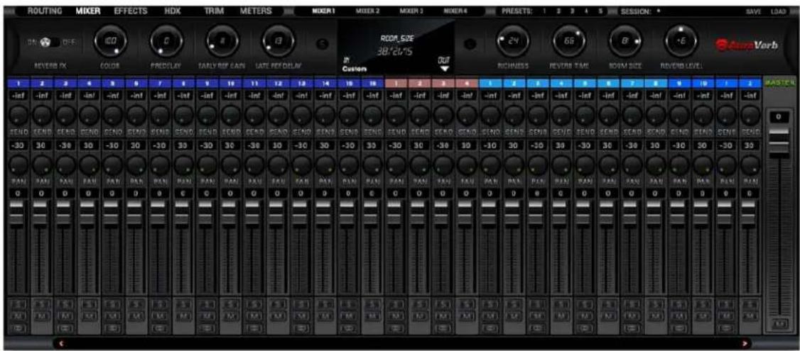
Mixer 1 has AuraVerb available as a Send effect for monitoring purposes. Turn the 'Send' knob on an audio channel to hear the reverb. The four mixers are otherwise identical.
AuraVerb
AuraVerb provides richness and color using a special new approach and an unique algorithm. The reverb features eight different controls, including a 'Color' parameter to create everything between darkened textures to bright, sizzling presence. In addition, there are 24 presets done by award-winning audio engineer and producer Brian

Vibberts. The following parameters are available in AuraVerb:
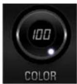
Color
The Color control lets you adjust the overall tone of the reverb. At 0, the space created is darker, like a lushly carpeted area. At 100, the reverb is at its brightest, which can add some 'sizzle' to a lead vocal, for example.

PreDelay
Common for most reverbs, the pre-delay lets you create a bit of space between the source and the onset of reverb. This happens by controlling the amount of delay time that precedes the initial sound from the reverb.
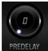
This parameter is used to place the reverberated signal later in time with respect to the unprocessed signal.
Natural settings for this are based on the size of the environment and range from 0 to 32 milliseconds. Fine adjustment of this parameter with respect to the tempo of the song or dramatic timing of the piece can help set the feel of the reverb within the mix.
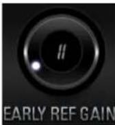
Early Reflection Gain
This is the linear gain value for all early reflections. These reflections are perceptually grouped with the direct sound when set at lower levels, and can nicely thicken a track when increased.
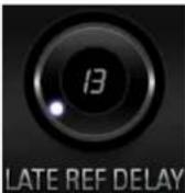
Late Reflection Delay
Among other things, AuraVerb calculates reflected energy from the side walls and ceiling of the virtual space. Late Reflection Delay controls the delay of these bursts of reflections, either creating echoes or supporting the spatial impression of the simulated acoustic space.
Richness
Richness controls the complexity of the reverb envelopment and dampening nuances. At 0, there is less dampening and a brighter decay. This sound is light or airy, but by increasing the Richness, you can add a

sense of spaciousness to the sound and smoothly increase reverb time for lower frequencies.

Reverb Time
Reverb Time controls the length of decay, while Room Size increases the virtual space dimensions. The perceived decay time will also be affected by Richness and Color on sources with a lot of high frequency
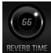
content. Generally, as the size of the space increases, the Reverb Time will also increase. Setting Reverb Time to 50% gives a natural sounding tail for all room sizes. Interesting big spaces or subtle ambience reverbs can be created by setting Reverb Time unusually high or low with respect to the Room Size parameter.
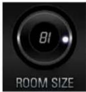
Room Size
Room Size increases the virtual space dimensions
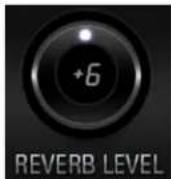
Reverb Level
This is the output level control of the reverb. Since inputs for AuraVerb are assigned to Send knobs on Mixer 1's channels, we recommend balancing the channel volume levels from the Send controls and using Reverb Level to adjust the amount of reverb in the Master bus.
REVERB FX ON/OFF Switch
Use it to enable and disable AuraVerb.
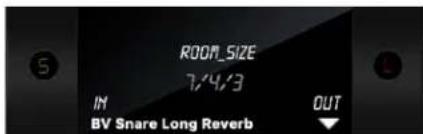
Preset Manager
The Preset Manager lets you save and load presets. Use the drop-down menu to choose a preset. Use the 'S' button to save a preset. Use the 'L' button to load a preset.
Effects tab
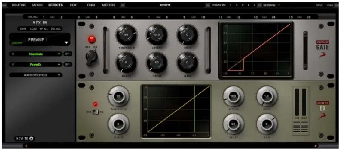
The 'Effects' tab lets you apply up to 8 FPGA FX per mono audio channel for a total of 16 channel strips and 128 FX instances, independent of sample rate. However, different types of FX place different processing loads, resulting in the following instance limitations:
- Feed-Forward Compressors (PowerFFC, X903, VCA160) - 16 instances
• Powergate - 12 instances - Feedback Compressors (FET-A76, Liverpool, Gyratec X, Tube176, Stay-Levin, ALT-436C, SMT-100A, FETA-78, BA-6A, Tubechild670, Impresser, BAE100CF) - 16 instances
• Equalizers (all) - 40 instances
• Reverb (AuraVerb) - 1 instance
1. FX Basics
- Route audio to the 'AFX IN' row inputs in the 'Routing' tab.
- Click the audio input (or linked pair) you want to work on:

- 'Link' buttons are available for each pair of inputs. Linking two inputs means the exact same FX processing is applied to both. Names of inputs and linked inputs are shown immediately above the Presets drop-down menu on the left.
- The 'DEL ALL' button clears all FX racks for all audio channels.
- Click the 'ADD NEW EFFECT' drop-down menu to choose and add effects. Their instances will appear in the FX Rack to the right. The list on the left lets you drag to re-order.
- Use the 'SAVE' and 'LOAD' buttons to store FX chains.
- Use the 'BP ALL' and 'DEL ALL' buttons to bypass or delete all FX on the current channel.
- Individual 'BP' (bypass) buttons are available next to each effect on the left side.
- Hold Ctrl (Windows) or Command (Mac) and drag to adjust FX parameters in smaller increments.
2. FX List
Goliath HD | Gen. 3 ships with a library of 36 FPGA FX. The following products are included:
COMPRESSORS & LIMITERS
FET-A76
- POWERFFC
- STAY-LEVIN
VCA160
• X903
EQUALIZERS
- CLEARQ
- VEQ-1A
- VEQ-HLF
- VMEQ-5
MIC PREAMPS
BA-31
• GYRAF GYRATEC IX TUBE
REVERB
- AuraVerb
UTILITY EFFECTS
- POWEREX
- POWERGATE
OTHER
• Guitar Amps & Cabs (Complete Collection)
• Edge & Verge Mic Emulations
Notes:
- More information about each effect is available here. Additional FX can be purchased from our website.
- .User manuals for the equalizers and compressors are available here
Guitar Amps & Cabs
Among everything else it does, the Goliath HD | Gen. 3 rocks! A suite of 11 guitar amps and matching cabinets lets you monitor and record the roar of your electric guitar in real-time. There's a bass rig in there too, so plug-in and get slappin'! If you don't play guitar, but like the sound of cooked-up tubes and speaker cabinets pushing air, route any audio into these bad boys and check what happens!
Getting Started
Guitar amps and cabs are used like almost any other effect. Here are the basics:
- Connect your electric guitar or bass to one of the four Hi-Z/instrument inputs on the device's front panel using a standard 1/4-inch TS instrument cable.
- Open the Control Panel application and head to the 'Hi-Z FRONT' tab. Adjust input gain as you play the instrument, careful not to run the meter into the red.
- Enter the 'Routing' tab and drag the colored number block corresponding to your 'INSTRUMENT' input onto a block from the row labeled 'AFX IN'.
- Drag the 'AFX OUT' block that corresponds to your 'AFX IN' block (same number) onto the output(s) you want to monitor and record from.
- Enter the 'Effects' tab. Click the input which corresponds to the 'AFX IN' block. Click the 'ADD NEW EFFECT' button to choose an amp first, then click again and choose a cabinet. Here's a textbook California-style heavy metal rig, for example:
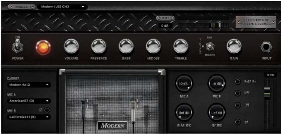
While the guitar amps don't really need an explanation, the cabinet module is worth examining:
- Change the cabinet model anytime from the 'Cabinet' drop-down menu.
- Change your cabinet's mics from the 'Mic A' and 'Mic B' drop-down menus. Click the adjacent 'Phase' button if your choice of microphones results in phasing issues.
- Click and drag the virtual microphones to adjust their vertical and horizontal positioning.
- Click and turn the 'Mic A' and 'Mic B' knobs to dial-in the amount of signal you want from each microphone.
- Click and turn the 'Rear Mic' knob to mix-in signal from an additional mic behind the cabinet.
- Click and turn the '45-degree Mic' knob to mix-in signal from an additional mic positioned at a 45-degree angle from a speaker cone.
- Click the 'ReSPiRe' button to hear some cab sim mojo courtesy of our friends from Overloud. In their own words, the ReSPiRe technology lets you switch
between the 'real' response of the cabinet and a processed version optimized to fit into a mix and avoid frequency overlap with the other instruments.
- Click the 'HPF' button to engage a preset high-pass filter (tames excessive low end).
- Click the 'LPF' button to engage a preset low-pass filter (tames harsh or shrill-sounding highs).
- Click the 'BP' button to bypass the cab sim.
Note: You can disable the FPGA cab sim and use custom guitar cabinet IRs in your DAW with your preferred IR Loader.
Re-amping
Re-amping is the practice of running entire guitar performances, recorded in the form of completely 'uncolored' signal from the instrument's pickups, through all kinds of guitar amplification and recording equipment. This way, guitar performances can be tightly edited prior to amplifying, and professionally recorded in conditions that are impractical or out of the player's reach.
Prior to pro audio manufacturers turning their attention onto the phenomenon, re-amping was usually accomplished using standard line outputs with Direct Injection (DI) boxes attenuating the signal from line-level to instrument-level accepted by guitar amplifiers. However, not all DI boxes are built equal, and subpar design would inevitably result in unflattering coloration and signal degradation. And then there were the adventurers who ran their line outs straight into the amplifier, attenuating the signal from the DAW's volume faders hoping no one gets hurt...
Luckily, we live in a more civilized age. A typical workflow for re-amping with the Goliath HD | Gen. 3 would be:
-
Connect the REAMP outputs to your guitar equipment's inputs using standard 1/4-inch TS instrument cables.
-
Place your guitar DIs onto tracks in your DAW and assign them to Outputs 1–64. These outputs send audio to the 'TB/USB/HDX PLAY' rows in the Control Panel's Routing Matrix.
-
Head to the 'Routing' tab and route up to two 'TB/USB/HDX PLAY' channels into the 'REAMP' outputs.
-
Next, route the inputs you will be recording from into the 'TB/USB/HDX REC' rows. Set up DAW tracks to record audio from them - e.g. 'TB REC' 1 = DAW 'Input 1'.
-
Hit 'Play' and you should be hearing your performance through your guitar rig. Shape your tone and start recording when you are ready.
Notes:
- Attenuate REAMP volume if you are overdriving the amplifier's front end.
- It's possible to use the REAMP outputs as Sends for external equipment, but we cannot recommend this unless said equipment has preamps to amplify the very quiet instrument-level signal. You are better off using the insert patch points on the rear panel for Send/Return configurations.
Software re-amping
You can re-amp DI guitar tracks through the FPGA Amps & Cabs as well:
-
Open your DAW. Place your DI on a track and assign it to one of Outputs 1-64. Remember: DAW Outputs = 'TB/USB/HDX PLAY' inputs.
-
Open the Control Panel. Enter the 'Routing' tab and drag the 'TB/USB/HDX PLAY' block onto an 'AFX IN' block.
-
Enter the 'Effects' tab and click the channel you want to work on.
-
Stack your amps, cabs and FX by clicking the 'ADD NEW EFFECT' button.
-
Hit 'Play' in your DAW's transport controls to hear the sound as you shape your tone.
-
If you want to record the result, route the corresponding 'AFX OUT' block onto an available 'TB/USB/HDX REC' output and record from it in your DAW.
Edge & Verge Mic Emulations
natural_image
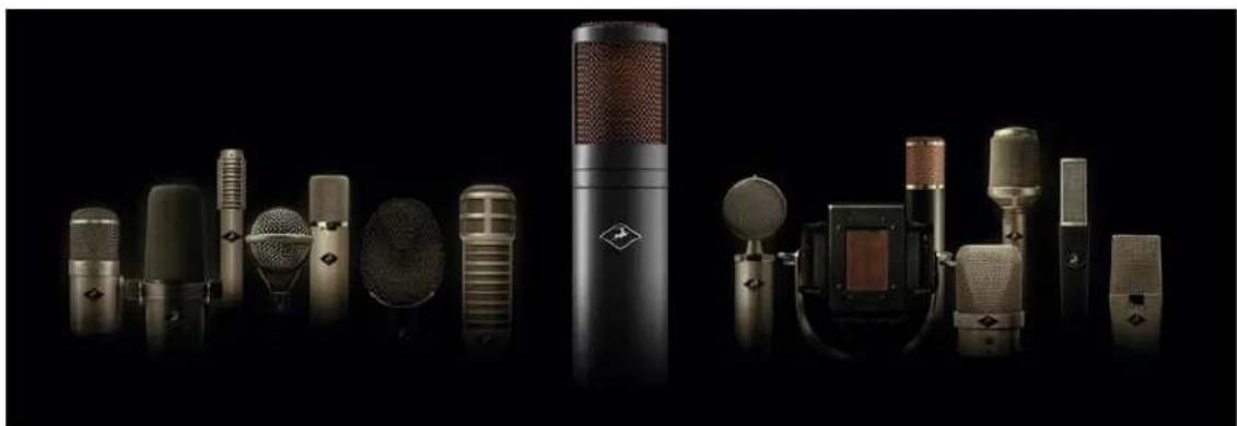
Product display of various vintage-style microphones against a black background (no text or symbols visible)Edge & Verge mic emulations are available on mic/line inputs 1 - 16. They are intended for use with the Antelope Audio Edge & Verge modeling microphones only. We cannot guarantee optimal (or even usable) results with other microphones.
Before attempting to use mic emulations, make sure of the following:
-
The mic emulations for your modeling microphone are installed from the 'Software' tab in the Antelope Launcher. Install them if they are not.
-
The installed mic emulation bundles are assigned to your Goliath HD | Gen. 3.
Getting Started
Mic emulations are accessed by clicking the tiny 'Mic' symbol, seen on all inputs in the 'PREAMPS' tab when they are set to 'Mic' from the drop-down menu:

Gain Calibration
It's a good idea to connect your mic(s) now and calibrate preamp gain before you proceed. To do this, switch the input(s) occupied by your mic(s) to 'Mic' from the dropdown menu(s) and activate 48V phantom power. Click and turn the Gain knobs or double-click the text fields and enter values from the keyboard.
Gain adjustment for the Edge Solo and Verge is straightforward, but the Edge Duo and Edge Quadro are multi-membrane microphones. There may be differences in the input signal strength from each membrane, which may have to be compensated for with individual gain adjustments.
Note that engaging mic emulations for Edge Duo and Edge Quadro automatically 'links' their input channels, thus individual gain adjustments per input are not possible while using their mic emulations.
Using Mic Emulations
In the 'Mic Emulations' window, click and rotate the dial to access the emulations available for your modeling microphone:
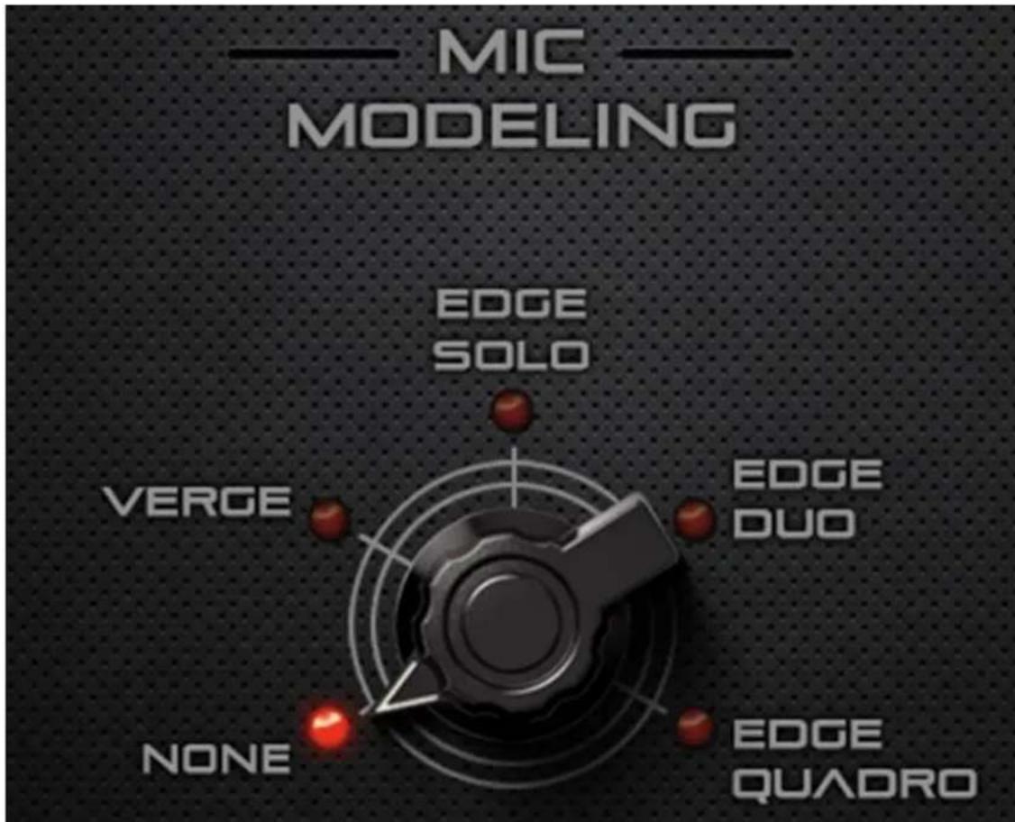
Following is a guide to using the mic emulations for each Antelope Audio modeling microphone:
Edge Solo
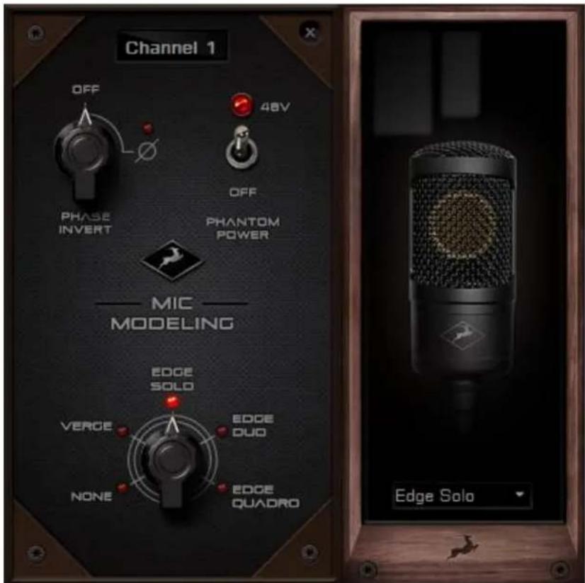
Edge Solo Mic Emulations Window
The following functionality is available:
- Choose mic emulations from the drop-down menu on the right.
- Click and turn the 'Phase Invert' dial to flip the microphone's polarity.
- Click and drag the '48'V switch to activate or turn off phantom power.
Recording and Monitoring Edge Solo
Edge Solo is a single-membrane condenser microphone. This means the microphone will occupy one physical mic preamp input, one block in the Routing Matrix 'PREAMP' row, and one block in the 'MIC EMU' row.
Edge Solo mic emulations work on a single input audio channel. Recording and monitoring both 'dry' and 'mic emulation' audio means dealing with two mono tracks.
- Route the 'PREAMP' input for Edge Solo to your desired outputs to monitor 'dry' audio. Route to a 'TB/USB/HDX REC' block to record from the corresponding input in your DAW.
- Route the 'EMU MIC' output for Edge Solo (same number as the 'PREAMP' input) to your desired outputs to monitor 'mic emulation' audio. Route to a 'TB/USB/HDX REC' block to record from the corresponding input in your DAW.
- Route 'PREAMP' and 'EMU MIC' blocks to your desired outputs and 'TB/USB/HDX REC' channels to monitor and record both 'dry' and 'mic emulation' audio.
For more information about Edge Solo, visit its product page.
Edge Duo
Edge Duo is included with your Goliath HD | Gen. 3 as a compliment from Antelope Audio.
The following functionality is available:
- Choose mic emulations from the drop-down menu in the middle.
- Click and turn the 'Phase Invert' dial to flip the microphone's polarity.
- Click and drag the '48V' switch to activate or turn off phantom power.
- Click and turn the 'Channel Swap' dial to swap the Edge Duo inputs.
- Click and turn the 'Pattern' knob to adjust the polar pattern. Note that some mic models have fixed or limited polar pattern adjustment.
Recording and Monitoring Edge Duo
Edge Duo is a dual-membrane condenser microphone – it has one capsule with dual membranes and connects with an Y-XLR cable (included), one XLR connector for each membrane. The Left (white) connector is the front membrane, the Right (red) is for the rear membrane.
The microphone occupies two physical mic preamp inputs, two blocks in the Routing Matrix 'PREAMP' row, and two blocks in the 'EMU MIC' row.
Note: You can use Edge Duo as a single-membrane condenser mic by disconnecting one of the XLR connectors. In this case, the mic emulations will be visible but they won't function correctly, you cannot swap inputs and you cannot adjust polar pattern.
Recording and monitoring Edge Duo as a single-membrane condenser mic Route the 'PREAMP' input for Edge Duo to your desired outputs to monitor 'dry' audio. Route to a 'TB/USB/HDX REC' block to record from the corresponding input in your DAW.
Recording and monitoring Edge Duo as a dual-membrane condenser mic In this case, you will record and monitor two concurrent mono inputs, one coming from each membrane. They will sound slightly different in tone and volume, due to the physical distance between the membranes and the performer. You may have to compensate with individual gain adjustments for each membrane.
Route the 'PREAMP' inputs occupied by Edge Duo to your desired outputs to monitor 'dry' audio. Route them to 'TB/USB/HDX REC' blocks to record from the corresponding inputs in your DAW.
Recording and monitoring Edge Duo as a modeling microphone Make sure that 'Edge Duo' mic emulations are enabled. Route the 'MIC EMU' inputs corresponding to the 'PREAMP' inputs occupied by Edge Duo to your desired outputs for monitoring and the 'TB/USB/HDX REC' blocks for DAW recording.
Recording and monitoring 'dry' and 'mic emulation' audio simultaneously With the Edge Duo, monitoring and recording 'dry' and 'mic emulation' audio simultaneously means handling four concurrent mono signals – two 'dry' tracks and two 'mic emulation' tracks. 'Dry' audio comes from the 'PREAMP' inputs, and 'Mic Emulation' audio comes from the 'MIC EMU' outputs. Route them anywhere you want in the Routing Matrix.
For more information about Edge Duo, visit its product page
Edge Quadro

Edge Quadro is a quad-membrane condenser microphone – it has two heads, each with dual membranes. The Top head rotates 360-degrees, enabling stereo recording techniques such as M/S, X/Y, Blumlein, and even 3D sound. Therefore, the microphone is bundled with a pair of Y-XLR cables. Their Left (White) connectors are for the front membranes, and their Right (red) connectors are for the rear membranes.
However, each cable is designated for either the Top or Bottom head, and labeled accordingly – T (Top) or B (Bottom). The inputs on the microphone are labeled too, letting you know where each cable needs to be connected.
There's a bevy of options for connecting Edge Quadro to your Goliath HD | Gen. 3:
As a single-membrane (rotatable) condenser mic. Connect just one XLR from the Top (rotatable) or Bottom head using the corresponding cable. The possible configurations are:
- Top Head – Front Membrane.
- Top Head – Rear Membrane.
- Bottom Head – Front Membrane.
- Bottom Head – Rear Membrane.
As a dual-membrane (rotatable) condenser mic. Connect two XLRs from either (or both) the Top and Bottom heads with the corresponding cables. The possible configurations are:
- Top Head – Front and Rear Membranes.
- Bottom Head - Front and Rear Membranes.
- Top Head - Front Membrane. Bottom Head - Front Membrane.
- Top Head - Front Membrane. Bottom Head - Rear Membrane.
- Top Head – Rear Membrane. Bottom Head – Front Membrane.
- Top Head – Rear Membrane. Bottom Head – Rear Membrane.
As a quad-membrane rotatable condenser microphone. Connect all XLRs from both heads with the corresponding cables. This is the only option for using the Edge Quadromic emulations.
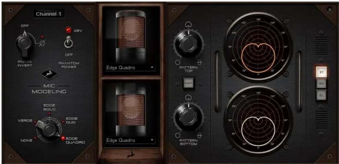
Edge Quadro Mic Emulations Window
Edge Quadro and Edge Duo mic emulations are identical, except for the ability to apply two different mic emulations in unison - one for each head - complete with two different polar patterns that are also swappable. All in all, the functionality is the same, but with two mic emulation selectors and two polar pattern changers.
Monitoring and recording Edge Quadro
Taking full advantage of the Edge Quadro's 360-degree recording and dual-emulation capabilities means the microphone will occupy four physical mic preamp inputs, four blocks in the Routing Matrix 'PREAMP' row, and four blocks in the 'MIC EMU' row.
Monitoring and recording 'dry' and 'mic emulation' audio simultaneously with the Edge Quadro means handling eight concurrent mono tracks – two 'dry' tracks from its Top head, two 'dry' tracks from its Bottom head, two 'mic emulation 1' tracks and two 'mic emulation 2' tracks.
With so many signals available, the routing and processing possibilities are extensive. Put the manual down and explore your skills and creativity.
For more information about Edge Quadro, visit its product page.
Verge
natural_image
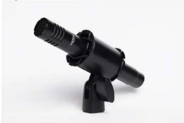
Black handheld device with threaded shaft and adjustable base, isolated on white background (no text or symbols visible)Verge is a small-diaphragm condenser microphone that's as simple to use as the Edge Solo. Its dimensions and ability to handle high sound pressure levels make it a better fit for positioning in tight spaces and recording very loud sources, such as drum kits.
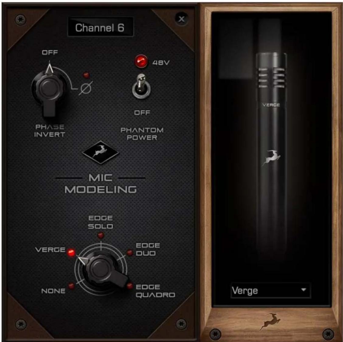
Verge Mic Emulations Window
The following functionality is available:
- Choose mic emulations from the drop-down menu on the right.
- Click and turn the 'Phase Invert' dial to flip the microphone's polarity.
- Click and drag the '48'V switch to activate or turn off phantom power.
Recording and Monitoring Verge
Verge is a single-membrane, small-diaphragm condenser microphone. This means the microphone will occupy one physical mic preamp input, one block in the Routing Matrix 'PREAMP' row and one block in the 'MIC EMU' row.
Verge mic emulations work on a single input audio channel. Recording and monitoring both 'dry' and 'mic emulation' audio means dealing with two mono tracks simultaneously.
- Route the 'PREAMP' input for Verge to your desired outputs to monitor 'dry' audio. Route to a 'TB/USB/HDX REC' block to record from the corresponding input in your DAW.
- Route the 'EMU MIC' output for Verge (same number as the 'PREAMP' input) to your desired outputs to monitor 'mic emulation' audio. Route to a 'TB/USB/HDX REC' row to record from the corresponding input in your DAW.
- Route 'PREAMP' and 'EMU MIC' blocks to your desired outputs and 'TB/USB/HDX REC' inputs to monitor and record both 'dry' and 'mic emulation' audio.
For more information about Verge, visit its product page
HDX tab
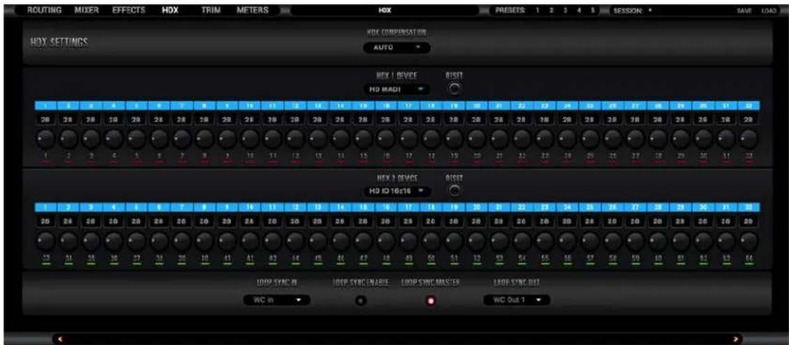
This tab is dedicated to setting up and optimizing the device for Pro Tools Ultimate.
1. HDX Device Setup
To make streaming up to 64 channels of sample-accurate audio into Pro Tools Ultimate possible, the Goliath HD | Gen. 3 is treated as a pair of 32-channel HDX devices. The 'HDX Device' 1 and 2 drop-down menus let you choose how they are represented in Pro Tools. Each of the available choices refers to real-life HDX hardware.
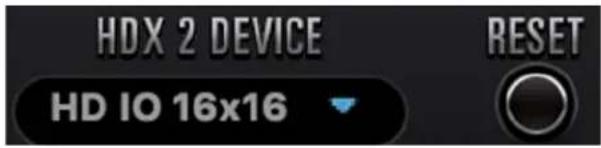
If you are accustomed to a certain Pro Tools HDX setup, choose the device you are most comfortable with or the one required for your session (if so). Otherwise, stick to 'HD IO 16x16' as it gives you the maximum amount of samples for manual delay compensation adjustments.
Regardless of choice, you always get 32 channels per device, and the latency differences between devices are always compensated for.
Notes:
- While it's possible to operate two 'different' HDX devices, we recommend keeping both the same.
- Pro Tools Ultimate must be relaunched after any HDX Device changes. We also recommend heading to the 'I/O Setup' window, selecting and deleting all channels (Inputs, Outputs, Busses, etc.), and clicking 'Default'.
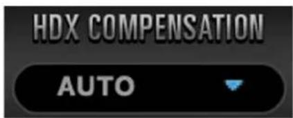
HDX Compensation
Choose the latency compensation mode – automatically or manually, in user-defined samples. The 'None' setting disables latency compensation.
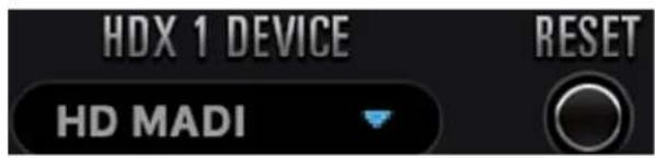
HDX 1 Device
Choose how the Goliath HD | Gen. 3 is represented in Pro Tools Ultimate for audio channels 1 - 32. Use the 'Reset' button to go back to default.
HDX 2 Device
Choose how the Goliath HD | Gen. 3 is represented in Pro Tools Ultimate for audio channels 33 - 64. Use the 'Reset' button to go back to default.
Audio Source Indicators
Available for both HDX devices, these strips indicate which audio source is being fed to each HDX input. There are up to 32 inputs per HDX device. The colored blocks mirror the Routing Matrix's current arrangement - any changes made there will be immediately visible here.
Latency Adjustment Knobs

When in manual latency compensation mode, use the knobs to adjust latency compensation (in samples) for each of the audio channels. You can also double-click the number boxes and enter values from the keyboard. While adjusting samples, look out for the following indicators:
A red line indicates that there are no more samples available to compensate for this channel. Turn the latency adjustment knob counter-clockwise until the indicator goes green.
Note: The knobs change latency in increments of two samples by default. Hold Ctrl
(Windows) or Command (Mac) and drag to adjust in one-sample increments.
2. Loop Sync Setup
If you want to connect another digital audio device to your HDX system alongside the Goliath HD | Gen. 3, you must synchronize the two in a Master - Slave arrangement where the Master device "clocks" the Slave device with its timing reference signal. In the realm of Pro Tools, this is known as 'Loop Sync'.
We recommend taking advantage of the Goliath HD | Gen. 3's highly stable and musical clocking, provided by an oven-controlled crystal oscillator and proprietary 64-bit algorithms (Acoustically Focused Clocking & Jitter Management) to generate timing reference.
To set up the Goliath HD | Gen. 3 as the Master Loop Sync device:
- Connect Word Clock Out 1 or 2 to the Slave device's Word Clock In using a standard BNC cable.
- Open the 'HDX' tab and choose the relevant Word Clock Out from the 'Loop Sync Out' drop-down menu.
- Click 'Loop Sync Enable'. The 'Loop Sync Master' indicator lights green.
Note: The receiving device might require modifying its settings to act as Slave.
To change the Master - Slave configuration from Pro Tools 'Hardware Setup' window:
- Connect Goliath HD | Gen. 3 - Word Clock Out to Device 2 - Word Clock In.
- Connect Device 2 - Word Clock Out to Goliath HD | Gen. 3 - Word Clock In
- Click 'Loop Sync Enable' in the 'HDX' tab.
Further reading:
- For a primer on digital clocking and jitter, read this article. More in-depth information can be found here.
• This interview is also very illuminating.
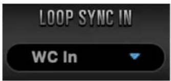
Loop Sync Input Selector
This drop-down menu lets you choose an external Loop Sync source - Word Clock Input (represented as WC In) or Atomic (Antelope Audio 10M/10MX Atomic Master Clock)
Loop Sync Enable
Click to enable (lit) or disable Loop Sync.
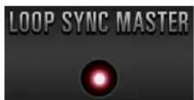
Loop Sync Master Indicator
When green, the Goliath HD | Gen. 3 is the Master Loop Sync source. When red, the device acts as Slave.
Loop Sync Output Selector
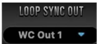
This drop-down menu lets you route Loop Sync signal to Word Clock Out 1 or 2 (represented as WC Out 1 and WC Out 2)
Trim tab
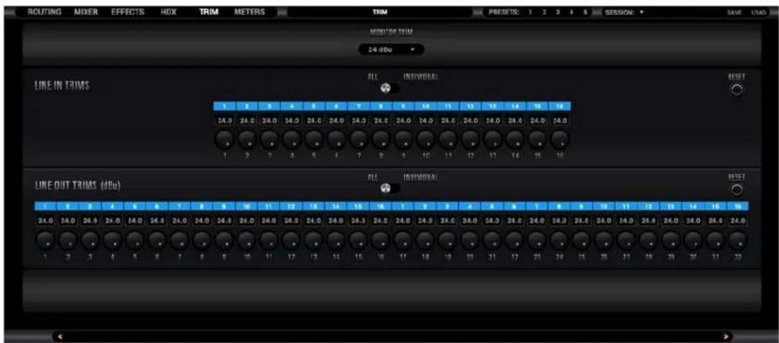
This tab is dedicated to signal trim adjustments for all Line I/O and Monitor outputs.
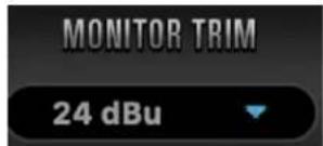
Monitor Trim
Choose a setting for the Monitor output signal trim.
All/Individual Switches
Position 'All' links trim values for all input or output audio channels. Change any one channel's trim value and the same value will be applied to the rest.
Position 'Individual' enables per-channel trim adjustments.
Audio Source Indicators
These strips indicate which audio source is being fed to each HDX input (Line In Trims) and output (Line Out Trims). There are up to 32 outputs per HDX device. The colored blocks mirror the Routing Matrix's current arrangement - any changes made there will be immediately visible here.
'Reset' buttons
Return line trim values to default.
Line In/Out Trim Knobs

The knobs let you adjust signal trim (in dBu) for each line input/output when the A/I switch is in the 'Individual' position. Double-click the text fields to enter values manually.
Meters tab
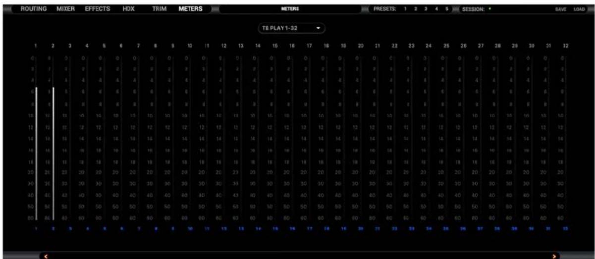
The 'Meters' tab provides up to 32 individual peak meters for each row from '6.4.1.
Routing tab - Terminology', selectable from the drop-down menu.
CUSTOMER SUPPORT INFORMATION
Antelope Audio Customer Support can be reached by the following means:
Online
Visit support.antelopeaudio.com
Phone
US time: 12AM (midnight) – 8PM (CST), Monday – Friday
US Phone Number: (916) 238-1643
European time: 6AM – 2AM (GMT), Monday – Friday.
UK Phone Number: +44 1925933423
Live Chat
US time: 12AM (midnight) – 2PM (CST), Monday – Friday
European time: 6AM – 8PM (GMT), Monday – Friday.
Note: If you're trying to reach us outside working hours, we advise you to file a ticket in our customer support system or leave a voice message.
Additional Resources
- The Antelope Audio YouTube channel is home to various tutorial videos and endorser content which you may find helpful and inspiring.

- The Antelope Audio Users Facebook group lets you interact with fellow users and some of our employees. Note, however, that it is not meant to be a support group. Please contact our customer support team for such inquiries.
- The Knowledge Base in our Customer Support section is an often-overlooked source of troubleshooting information, answers to commonly asked questions and Antelope know-how.
MY ANTELOPE AUDIO PRODUCT ISN'T WORKING.
What should I do?
If you can't find a solution on your own, please get in touch with us so we check if you are having a hardware-related issue. If this is the case, we'll guide you through the repair process. If the product should be returned, a RMA number will be issued so we can begin the procedure.
What's an RMA number?
Issuing a RMA (Return Merchandise Authorization) number is required for any factory service or repair procedure. Please, don't attempt to send us your device without receiving a RMA number first, as the device will be returned and not serviced.
How do I get an RMA number?
The Antelope Audio Customer Support team is in charge of issuing RMA numbers. Visit support.antelopeaudio.com and get in touch.
After your RMA has been issued, you will receive an email with instructions on how to proceed.
RMA shipping information
Alongside the product you are returning please, include a letter containing your full name, shipping address, RMA number issued by our technical support team and a note with a short information about the technical issue.
Please use the original box if possible, because a worn out one will surely not protect your product sufficiently on its way to the Antelope Audio HQ. Additional cushioning materials in multiple layers between the unit and the box walls to prevent from shock, vibration and various tears and scratches.
Please remove any labels or old shipment markings it may have and ensure you add your shipping address inside the box in case the original shipment label becomes illegible during transportation.
The shipping costs are covered by the owner of the product. Antelope Audio will not cover any local customs charges.
We recommend using a courier service of your choice (e.g. DHL, UPS, FedEx). The package should be insured for its real value, marked as fragile and a tracking number should be provided. We do not recommend using standard mail delivery services.
Please, don't forget to add the RMA number, issued by the Antelope Audio technical support, on all shipping paperwork.
Antelope Audio cannot be held responsible for undelivered packages – lost or damaged on the way to the Antelope Audio HQ. For damage claims, please contact your shipping service provider of choice.
Antelope Audio cannot cover any repair costs for product damages due to poor packaging.
LIMITED WARRANTY POLICY
This is a non-transferable voluntary Limited Product Warranty provided to end-customers who have purchased Antelope Audio-branded hardware product (hereinafter referred to as "Product") from an authorized Antelope Audio re-seller.
For customers covered by consumer protection laws or regulations in their country of purchase or, if different, their country of residence, the benefits conferred by Antelope Audio's Limited Warranty are in addition to, and not instead of, rights and remedies convened by such consumer protection laws and regulations and it does not exclude, limit or suspend buyer's rights arising from consumer law. Consumers have the right to choose whether to claim service under the Antelope Audio Limited Warranty or under their consumer law rights.
All claims made under the Antelope Audio Limited Warranty will be governed by the terms set out in this warranty document.
Warranty Coverage
Antelope Audio warrants that the Product will be free from defects in material and workmanship for the period of 1 (one) year commencing on the date of purchase of Product by end-customer from authorized Antelope Audio's re-seller.
Except where explicitly prohibited by applicable local law, this warranty is limited to the original purchaser and is non-transferable. This warranty provides you with specific legal rights, and you may have additional rights that vary under local laws.
In general, this warranty means your Antelope Audio hardware product will operate in accordance with published technical specifications, as specified by its data-sheet, and in the operating environment for which it was intended for the length of the warranty period.
This version of the warranty applies to products purchased on or after January1,2018. For prior versions of the Antelope Audio limited warranty, please contact customer service.
Limited Factory Refurbished (B-stock) Warranty
Antelope Audio warrants products sold as "B-stock, Factory Refurbished or Open Box" to be free from defects in materials (unless otherwise stated in product description) and workmanship. Only products purchased from an authorized dealer or directly from Antelope Audio are covered by this Warranty.
The Limited Factory Refurbished (B-stock) Warranty is valid for the period of 6 (six) months, commencing on the date of purchase of Product, if local regulations do not require otherwise.
All warranty terms contained hereunder apply also to the B-stock Warranty, unless otherwise specified.
Remedies
Antelope Audio's entire liability and your exclusive remedy for any Antelope Audio Product that is not operating in accordance with its published technical specifications is at Antelope Audio's discretion:
1) to repair the Product at Antelope Audio's expense using new or equivalent-to-new refurbished parts in good working condition; or
2) to replace the Product at Antelope Audio's expense with a product with equivalent functionality formed from new and/or equivalent-to new refurbished parts in good working condition, or
3) to refund the price paid. Should Antelope Audio decide to refund the price paid, it may deduct from the paid Product's price any damages caused to the Product; where, within fourteen (14) days of the expiration of the warranty period,(i) Antelope Audio has received written notice of any nonconformity;(ii) after Antelope Audio's written authorization, customer has returned the nonconforming product to the designated place; and (iii)Antelope Audio has
determined that the Product is nonconforming and that such non conformity is not the result of any of the exclusions designated below.
These warranty obligations are conditioned upon the hardware being returned to the original place of purchase, or another place as directed by Antelope Audio, with the original sales receipt attached. You will be required to pay shipping and handling charges for returning the product. You may be required to pay any other applicable tariffs, duties, taxes, or other fees with regard to returning the products.
Any repaired or replacement Product will be warranted for the remainder of the original warranty period.
Obsolete or Discontinued Products
An obsolete or discontinued product will be repaired or replaced with the same product if available. If Antelope Audio is unable to replace your obsolete or discontinued product with the same product, Antelope Audio will replace the obsolete or discontinued product, in its sole discretion, with a product having similar function and capacity.
Exclusions
This warranty does not cover problems or damage resulting from, but not limited to, any of the following: (i)Wear and tear associated with normal use; (ii)Any modification, abuse, accident, disassembly, misapplication, misuse, negligence, acts of God, accident; (iii)Unauthorized repair or attempted repair by anyone other than Antelope Audio or someone authorized by Antelope Audio to do warranty work; any unauthorized repairs will void this warranty(iv)Any improper operation, maintenance or installation, including any use not in accordance with any supplied product instructions; (v)Connection to any improper voltage supply; (vi)Use of consumables or spare parts not supplied by Antelope Audio, except where such restriction is prohibited by applicable local law;
(vii) Any other cause which does not relate to a Product defect in materials or workmanship.
The warranty does not apply to any Products which have been subject to misuse, neglect, accident or modification or which have been soldered or altered such that they are not capable of being tested under normal test conditions.
This warranty does not cover (i) any counterfeit products, i.e. Products that Antelope Audio, at its sole discretion, determines were not manufactured by Antelope Audio or any of its authorized manufacturing partners; (ii) Products purchased from a person or entity which is not an authorized dealer or re-seller of Antelope Audio; (iii) Product sold "as is" or "with all faults", to the extent permitted by local law.
This warranty is not valid in case any manufacturer label(s), serial numbers, date stamp(s) or warranty sticker(s) has been altered or removed from the Product.
Limitation of Liability
ANTELOPE AUDIO SHALL NOT BE LIABLE FOR ANY SPECIAL, INCIDENTAL, INDIRECT, OR CONSEQUENTIAL DAMAGES WHATSOEVER, INCLUDING BUT NOT LIMITED TO LOSS OF PROFITS, REVENUE, OR DATA (WHETHER DIRECT OR INDIRECT) OR COMMERCIAL LOSS FOR BREACH OF ANY EXPRESS OR IMPLIED WARRANTY ON YOUR PRODUCT EVEN IF Antelope Audio HAS BEEN ADVISED PREVIOUSLY OF THE POSSIBILITY OF SUCH DAMAGES. Some local laws do not allow the exclusion or limitation of special, indirect, incidental or consequential damages, so this limitation or exclusion may not apply in your jurisdiction.
ANTELOPE AUDIO WILL NOT ASSUME OR AUTHORIZE ANY OTHER PERSON TO ASSUME FOR IT ANY OTHER LIABILITY IN CONNECTION WITH ITS PRODUCTS.
Data Recovery
In the event of data loss using Antelope Audio storage devices, Antelope Audio is not responsible for backing up or recovering any data that you may have lost.
No Other Warranties
No Antelope Audio employee, dealer, re-seller, or other agent is authorized to make any modification, extension, or addition to this warranty.
How to Make a Warranty Claim
Valid warranty claims should be processed through your point of purchase. Please also verify the return policy directly with the retailer where you purchased your product. Any warranty claims that cannot reprocessed through your original point of purchase should be addressed directly to Antelope Audio. Our customer service contact information can be found on the web or in the documentation included with your Product.
Returning Your Product
In the event that you need to return your Antelope Audio products for repair or replacement, Antelope Audio will provide you with a Return Merchandise Authorization Number (RMA#) as well as return instructions. Do not return your product without prior approval from Antelope Audio. Any product returned without a valid unique RMA# will be refused and returned to the sender at the sender's expense. To avoid problems at the time of receipt, clearly write your RMA# on the outside of the package and include a copy of your RMA confirmation-mail within the package.
In certain situations, for in-warranty units, we may (entirely at our opinion) offer you a temporary replacement unit, provided that we have such on stock in your state. To request a temporary replacement unit, a valid credit card must be provided to secure the new replacement unit for shipping prior to Antelope Audio receiving the defective one.
Request a Return Material Authorization Number (RMA#)
Please follow these steps to obtain an RMA number:
(I) For end user customers, submit a claim online at: support.antelopeaudio.com. For business to business (B2B) / Direct customers of Antelope Audio please email us at techsupport@antelopeaudio.com
(ii) A valid proof of purchase is required for RMA processing (i.e. receipt, invoice, etc). Antelope Audio will provide you with the RMA number within 2 working days as of the claim submission date.
RMA Return Addresses
We have multiple RMA receiving locations worldwide. Your RMA confirmation will specify the specific return address you must use when sending your RMA package. Any packages received at an unauthorized location may be refused and returned to the sender at the sender's expense.
Products Lost or Damaged During Transit
The original packaging material should be used to pack the product for return; if the original packaging is not available, you should use such materials that provide the same or greater protection to the product. All packages that arrive with any external damage or appear inadequately packed will be refused and returned to the sender at the sender's expense. We are not responsible for damage incurred during shipping to our RMA receiving locations or for lost or stolen products.
Company information
Antelope Audio is the trade name, under which the company Elektrosfera Ltd., registered under the legislation of the Republic of Bulgaria with UIN: 131052590, is doing business and is worldwide known. Elsewhere in this document where the trade name Antelope Audio is used shall refer to Elektrosfera Ltd., with address of management: Tsarigradsko Shose Blvd., 7th km, Building of BIC IZOT, floor 6, Mladost region, Sofia, Bulgaria.
If any term hereunder is held to be illegal or unenforceable, it shall be severed from this warranty and the legality or enforce ability of the remaining terms shall not be affected.
SAFETY NOTES
To reduce the risk of electrical shocks, fire, and related hazards:
- Do not remove screws, cover, or cabinet. There are no user serviceable parts inside. Refer servicing to qualified service personnel.
- Do not expose this device to rain, moisture or spillover of liquid of any kind.
- Should any form of liquid or a foreign object enter the device, do not use it. Switch off the device and then unplug it from the power source. Do not operate the device again until the foreign object is removed or the liquid has completely dried and its residues fully cleaned up. If in doubt, please consult the manufacturer.
- Do not handle the power cables with wet hands!
- Make sure the device is switched off when plugging/unplugging it to/from the power source.
- Avoid placing things on the cabinet or using the device in a narrow and poorly ventilated place which could affect its operation or the operation of other closely located components.
- If anything goes wrong, turn off the device first and then unplug the power. Do not attempt to repair the device yourself. Consult authorized service personnel or your dealer instead.
- Do not install near any heat sources such as radiators, stoves, or other apparatus (including amplifiers) that produce heat.
- Do not use harsh chemicals to clean your unit. Clean only with specialized cleaners for electronics equipment.
- Connect all your devices before powering your unit.
- This unit is connected via its power cord to the mains safety earth. Never operate the unit without this earth connection.
- DC power supply cable should be routed so that it is not likely to be walked on or squeezed by items placed upon or against it.
- To completely turn off the device, unplug the power cable first from the outlet and then from the rear panel of the unit.
- Both occasional and continued exposure to high sound pressure levels can cause permanent ear damage via headphones and monitors.
- Your unit should always be un-racked when traveling or in a flight case.
- The device is designed to operate in a temperate environment, with a correct Operating Temperature of 0–50°C, 32–122°F.
TECHNICAL SPECIFICATIONS
| FRONT PANEL FEATURES | 1 x 3.5-inch high resolution TFT display (262 000 colors) with capacitive touch screen panel1 x Selectable rotary control knob with LED Ring indicating the volume or mute status of the chosen output16 x Gain control knobs for each microphone input (encoders have internal switch for muting)16 x RGB LEDs above each microphone gain control knob (input level indicators)4 x Gain control knobs for each Hi-Z instrument input (encoders have internal switch for muting)4 x RGB LEDs above each Hi-Z instrument input gain control knob (input level indicators)1 x TALKBACK microphone1 x MUTE button1 x MONO button1 x DIM button (with Antelope Audio logo) |
| ANALOG I/O - FRONT PANEL | 4 x Hi-Z instrument Inputs2 x ReAmp Outs2 x Headphone Outs |
| ANALOG I/O - REAR PANEL | 16 x Universal Inputs (Mic In/Line In) on combo-XLR16 x Line In on 2x DB25 +(used premium ADC mono structures with 124dB DNR; -112dB THD)32 x Line Out on 4x DB25 +(used audiophile premium quality DACs with )2 x AD Inserts on double TRS, inputs hard-wired to M/L inputs 1 - 21 x Monitor Line Out on 1/4-inch TS/TRS jacks (L/R CHs) |
| DIGITAL I/O | 1 x S/PDIF In on RCA (2 CHs)1 x S/PDIF Out on RCA (2 CHs)4 x AES/EBU In on DB25 (8 CHs)4 x AES/EBU Out on DB25 (8 CHs)1 x Atomic In on BNC1 x WC In on BNC (used for HDX Loop Sync also)2 x WC Out on double BNC (used for HDX Loop Sync also)2 x ADAT In on Fiber optic2 x ADAT Out on Fiber optic2 x Optical MADI In and Out on Fiber optic(64 channels on each MADI connector, 128 I/O channels total)1 x USB 3.0 (Type-B) - 64 I/O channels (8 I/O channels on USB 2) / Used alongside HDX Ports for Control Panel connection1 x Thunderbolt(TM) 2 - 64 I/O channels / /Used alongside HDX Ports for Control Panel connection2 x HDX Port (32 I/O channels on each port) |
| AUDIO CONVERSION | A/D (Analog-to-Digital)124dB DNR ; -112dB THDD/A (Digital-To-Analog)129dB DNR ; - 115dB THDMONITOR D/A (Monitor Output Conversion)136dB DNR ; -115dB THD |
| SAMPLE RATES (kHz) | 32, 44.1, 48, 88.2, 96, 176.4, 192 |
| DIGITAL CLOCKING | Word Clock Input1 x Input @ 75 Ohms 3Vpp on BNC 32 - 192kHzAtomic Clock Input1 x 10M Input @ 75 Ohms 1Vpp on BNCWord Clock Outputs2 x Outputs @ 75 Ohms 3Vpp on BNC 32 - 192kHzClocking System4th Generation Acoustically FocusedClocking & Jitter Management64-bit DDSOven Controlled Crystal OscillatorClock Stability<+/-0.02 ppm, oven controlled at 64.5°C/148.1°FClock Aging< 1 ppm per yearClock Calibration< +/-0.001 ppm |
| DEVICE DIMENSIONS | Width: 48.3cm / 19inDepth: 27.9cm / 11inHeight: 8.8cm / 3.5inWeight (net): 6.8kg / 15lbs |
| OPERATING TEMPERATURE | 0-50°C, 32-122°F |
| ELECTRICAL SPECS | AC Universal input: ~95-245 V |
- GOLIATH HD
- Gen 3
- CONTENTS
- BEFORE YOU BEGIN
- SETTING UP
- Notes:
- Need any help?
- Configuring for Windows 10
- Default Format
- Tips
- Further Reading
- Configuring for macOS 10.14 Mojave (or later)
- HDX Activation
- FRONT PANEL EXPLAINED
- REAMP Outputs 'R1' - 'R2'
- Hi-Z instrument inputs 'G1' - 'G4' with Gain Control Knobs and LED Indicators
- Touch Screen
- Mic/Line Inputs 1 - 16 Gain Control Knobs with LED Indicators
- Main Rotary Control Knob with LED Indicators and LED Ring
- Mono Button
- Antelope Button
- Mute Button
- REAR PANEL EXPLAINED
- Mains Power Connection
- Word Clock Input (Top)
- 10M Input (Bottom)
- Word Clock Outputs
- S/PDIF I/O
- ADAT I/O
- L/R Monitor Outs
- D-SUB 25-pin Line Outputs
- AES/EBU I/O
- MADI 1 - 2 I/O
- Thunderbolt™ 2 Port
- USB 3 Type-B Port
- HDX Ports
- D-SUB 25-pin Line Inputs
- AD Inserts 1 - 2
- Integrating External Analog Equipment
- Workflow
- Mic/Line Inputs 1 - 16
- TOUCHSCREEN FUNCTIONALITY
- 'MENU' Button
- Comm. Interface
- Scr Save Time
- Scr Save Style
- SR Conversion
- Presets Saving
- Factory Reset
- 10M Calibration
- Device Info
- Touch Scr Calibr
- Loop Sync Mode
- LS Input
- LS Output
- Clock Source
- Additional Functionality
- 'MON' Button
- 'AMP' Button
- 'TBK' Button
- 'P1' - 'P2' Buttons
- SOFTWARE CONTROL PANEL
- Quick Start
- Monitor incoming audio via headphones
- Apply FPGA FX to incoming audio
- Play guitar through the virtual amps and cabinets, listening from studio monitors
- Sing with microphone emulations and monitor live with headphones
- Route audio to your DAW for recording
- Mouse & Keyboard Shortcuts
- Main View
- Function Strip 1
- Monitor Volume
- Sample Rate
- Devices
- Settings Button
- MUTE
- OSCILLATOR 1
- LEVEL
- OSCILLATOR 2
- SRC
- MADI 1 IN/OUT & S-MUX
- MADI 2 IN/OUT & S-MUX
- TBK INPUT
- TBK HP1
- TBK HP2
- TBK MONITOR
- REAMP VOLUME
- LINE OUT VOLUME
- BUFFER SIZE (SAMPLES)
- USB STREAMING MODE
- TB LATENCY MODE
- Help Button
- Minimize Button
- Close Button
- Function Strip 2
- Input Gain Tabs
- Lock Indicator
- HP1 Volume and Mute
- HP2 Volume and Mute
- TBK Button and Volume
- Input Gain Tabs
- Text Label
- Gain Knob and Mic Emulations Button
- CHANNEL 1
- Mic/Line Input Selector
- Input Signal Strength Meter
- 48V Phantom Power Button
- Link Button
- Phase Flip Button
- ADAT IN tab
- S/PDIF IN tab
- Hi-Z FRONT tab
- Tab Selector
- Presets
- Sessions
- Routing tab
- Terminology
- PREAMP
- EMU MIC
- INSTRUMENT
- LINE IN
- TB PLAY 1 - 32 / 33 - 64
- USB PLAY & USB PLAY 2
- ADAT IN
- AES IN
- S/PDIF IN
- AFX OUT
- Low Latency Mixer Outputs
- TALKBACK
- LINE OUT
- HP1
- HP2
- MAIN MONITOR
- REAMP
- TB REC 1 - 32 / 33 - 64
- USB REC 1 & USB REC 2
- MADI1 OUT 1 - 32 / 33 - 64
- MADI2 OUT1 - 32 / 33 - 64
- HDX REC 1 - 32 / 33 - 64
- ADAT OUT
- AES OUT
- S/PDIF OUT
- AFX IN
- MIX CH1 - CH4
- Mixer tab
- Limitations
- AuraVerb
- Color
- PreDelay
- Early Reflection Gain
- Late Reflection Delay
- Richness
- Reverb Time
- Room Size
- Reverb Level
- REVERB FX ON/OFF Switch
- Preset Manager
- Effects tab
- FX Basics
- FX List
- COMPRESSORS & LIMITERS
- EQUALIZERS
- MIC PREAMPS
- REVERB
- UTILITY EFFECTS
- OTHER
- Guitar Amps & Cabs
- Getting Started
- Re-amping
- Software re-amping
- Edge & Verge Mic Emulations
- Gain Calibration
- Using Mic Emulations
- Recording and Monitoring Edge Solo
- Edge Duo
- Recording and Monitoring Edge Duo
- Edge Quadro
- Edge Quadro Mic Emulations Window
- Monitoring and recording Edge Quadro
- Verge
- Recording and Monitoring Verge
- HDX tab
- HDX Device Setup
- HDX Compensation
- HDX 1 Device
- HDX 2 Device
- Audio Source Indicators
- Loop Sync Setup
- To set up the Goliath HD | Gen. 3 as the Master Loop Sync device:
- Further reading:
- Loop Sync Input Selector
- Loop Sync Enable
- Loop Sync Master Indicator
- Loop Sync Output Selector
- Trim tab
- Monitor Trim
- All/Individual Switches
- 'Reset' buttons
- Line In/Out Trim Knobs
- Meters tab
- CUSTOMER SUPPORT INFORMATION
- Online
- Phone
- Live Chat
- Additional Resources
- MY ANTELOPE AUDIO PRODUCT ISN'T WORKING.
- What should I do?
- RMA shipping information
- LIMITED WARRANTY POLICY
- Warranty Coverage
- Limited Factory Refurbished (B-stock) Warranty
- Remedies
- Obsolete or Discontinued Products
- Exclusions
- Limitation of Liability
- Data Recovery
- No Other Warranties
- How to Make a Warranty Claim
- Returning Your Product
- Request a Return Material Authorization Number (RMA#)
- RMA Return Addresses
- Products Lost or Damaged During Transit
- Company information
- SAFETY NOTES
- TECHNICAL SPECIFICATIONS
Brand : Antelope
Model : Goliath HD Gen 3
Category : Hi-Fi System