
CG6BLS - Range hood Euromaid - Free user manual and instructions
Find the device manual for free CG6BLS Euromaid in PDF.


| Product Type | Canopy Range Hood |
| Model | CG6BLS |
| Brand | Euromaid |
| Dimensions (Width) | 600 mm (23.6 inches) |
| Material | Curved Glass & Stainless Steel |
| Voltage / Frequency | 220-240 V / 50 Hz |
| Motor Speed Levels | 3 (Low, Medium, High) |
| Control Type | Electronic push button or LCD touch with timer |
| Lighting Type | Halogen or LED (replacement LED assembly from supplier) |
| Light Bulb Power | Not specified (halogen: standard GU10, LED: integrated) |
| Filter Type | High-density stainless steel grease filter (non-stick, dishwasher safe) |
| Carbon Filter | Optional (not included, replaceable) |
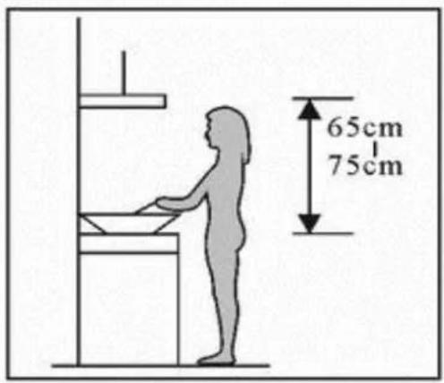
| Installation Height | 65-75 cm (26-30 inches) above cooking surface |
| Ducting Diameter | Standard (not specified, likely 150 mm) |
| Extraction Method | Ducted (external ventilation required) |
| Max Airflow | Not specified (estimated ~600-800 m³/h) |
| Noise Level | Low noise (specific dB not provided) |
| Safety Features | Auto shut-off timer, overheat protection, child safety warnings |
| Maintenance | Grease filter clean monthly; body clean with mild detergent; electrical isolation before cleaning |
| Warranty | Contact Home Appliances (1800 805 300) for service |
| Weight | Not specified (approx. 12-15 kg) |
Frequently Asked Questions - CG6BLS Euromaid
User questions about CG6BLS Euromaid
0 question about this device. Answer the ones you know or ask your own.
Ask a new question about this device
Download the instructions for your Range hood in PDF format for free! Find your manual CG6BLS - Euromaid and take your electronic device back in hand. On this page are published all the documents necessary for the use of your device. CG6BLS by Euromaid.
USER MANUAL CG6BLS Euromaid
600mm Curved Glass & Stainless Steel Canopy
MODEL
CG6BLS

HOME APPLIANCES
Dear Customer,
We thank you for choosing this quality appliance and hope you enjoy many years of reliable service.
Please ensure this manual is read carefully before installation and use. Keep this manual in a safe and accessible location should future reference be required.
Regards
Home Appliances
CONTENT
2 Notice
3 Caution
4 ...... Feature
5-8 ...... Installation
9 Notice of installation
10 Safety Warning
11-16 Use
17 Maintenance
18 Light Replacing
19 Abnormity and Solution
NOTICE
-
Thank you for choosing our canopy rangehood. Please read the instruction manual carefully before use.
-
The installation work must be undertaken by a qualified and competent fitter.
-
The manufacturer disclaims all liability for any damage or injury caused as a result of not following instructions for installation contained in the following text.
The cooker hood is used on 220/240v, 50Hz.
SAFETY WARNINGS
- Installation of this Integrated Canopy Rangehood must be carried by a qualified and competent installer.
- The manufacturer disclaims and liability for any damage or injury caused as a result of not following instruction of installation contained in this instruction manual.
- This Integrated Canopy Rangehood is not intended for use by young children or infirm persons without supervision.
- Young children should be supervised to ensure they do not play with this Integrated Canopy Rangehood.
- To avoid possible electric shock this Integrated Canopy Rangehood should be unplugged before any maintenance or cleaning is carried out.
- This Integrated Canopy Rangehood cannot be installed in an external environment.
- The Grease Filters should be cleaned at least once a month to avoid the risk of fire.
- Flambe cooking cannot be carried out under the Integrated Canopy Rangehood and is not recommended for use over Barbeques.
- Ducting must be independent from any other form of ducting of other household heating sources.
- Ducting into wall cavities is prohibited unless the cavity has been designed for this purpose
- Lit gas burner should never remain uncovered or on when there is no pan present due to the risk of fire.
- Adequate ventilation of the room is required when the cooker hood is used at the same time as appliances burning gas or other fuels.
- CAUTION: Accessible parts may become hot when used with cooking appliances.
(2)FEATURE
- The cooker hood uses high quality materials, and is made with a streamlined design.
- Equipped with a large power low noise electric motor and centrifugal leaf, it produces strong suction, low noise, non stick grease filter and easy to clean.
- With the isolated low voltage circuit board control, 12vAC input, the lights are therefore safer.
- Special wind tunnel construction and oil collector design, free dirt will be absorbed in a second.
(3). Installation
If the model without Glass:
3.1 The cooker hood shall be placed at a distance of 65-75cm (26-30inch) from the cooking surface. See Pic 1.
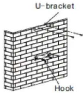
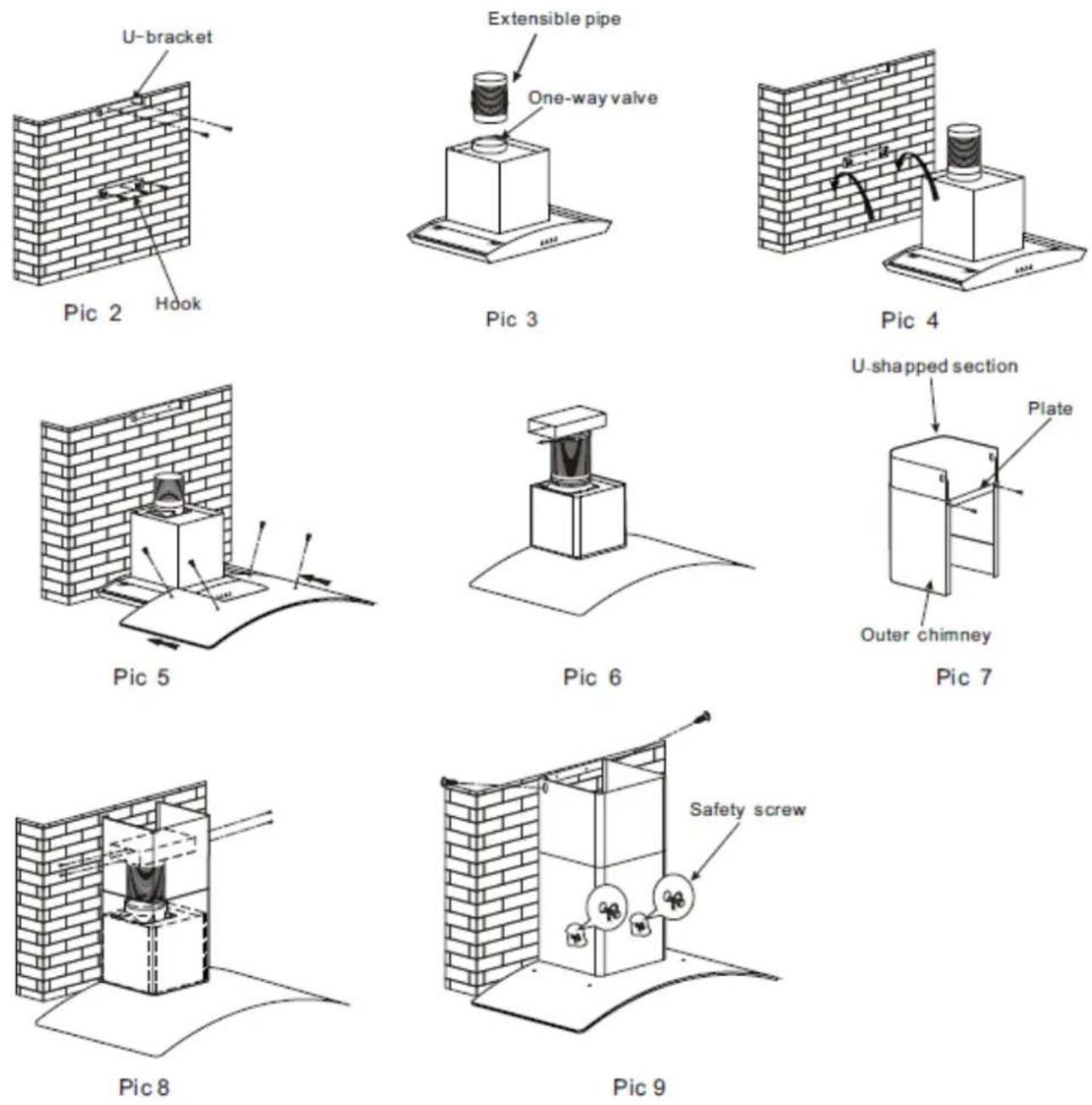
3.2 Install the hook on a suitable place once the installation height is fixed, and keep it in line. The fixed position of the inside chimney bracket is the place of chimney. See Pic 2.
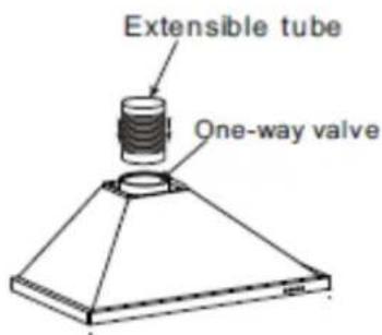
3.3 Fix one-way valve on the hood and connect the extensible pipe to the one-way valve. See Pic 3.
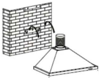
3.4 Put the cooker hood on the hook. See Pic 4.
3.5 Use clamp to fix the T-piece valve on the extensible pipe. See Pic 5.
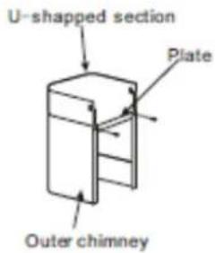
3.6 Fix plate on the outer chimney, and be sure that the inside chimney can be adjusted the height in it freely. See Pic 6.
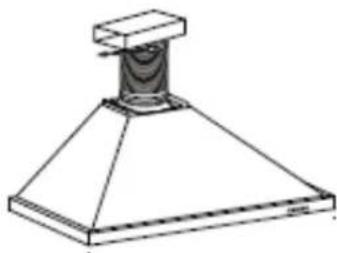
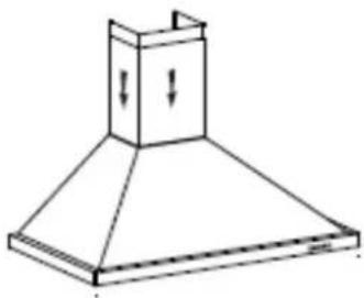
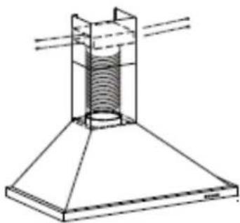
3.7 Install the chimney and screw the T-piece metal outlet to the inside chimney, See Pic 7 and 8.
3.8 Adjust the height of the inside chimney to the position of the inside chimney bracket and fix on it by screw, after adjusting the position, fix the body with safety screw. See Pic 9.
Note: The two safety vents are positioned on the back casing, with diameter of 6mm.
Pic1
Pic 2
Pic 3
natural_image
Diagram of a brick wall and a conical lamp setup with a chimney, showing no text or symbols.Pic 4
natural_image
Technical line drawing of a conical mechanical component with a base and top (no text or symbols)Pic 5
Pic 6
natural_image
Line drawing of a double-bell tower with ventilation duct and downward arrows indicating airflow or pressure (no text or symbols)Pic 7
natural_image
Technical line drawing of a mechanical assembly with a conical base and cylindrical component (no text or symbols)Pic 8
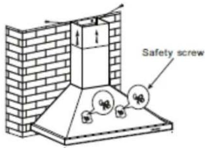
Pic 9
Warning: Failure to install the screws or fixing device in accordance with these instructions may result in electrical hazards
If the model with Glass:
3.1 The cooker hood shall be placed at a distance of 65-75cm (26-30inch) from the cooking surface. See Pic 1.
3.2 Install the hook on a suitable place once the installation height is fixed, and keep it in line. The fixed position of the inside chimney bracket is the place of chimney. See Pic 2.
3.3 Fix one-way valve on the hood and connect the extensible pipe to the one-way valve. See Pic 3.
3.4 Put the cooker hood on the hook. See Pic 4.
3.5 Put the glass according to the lead direction and way on the cooker hood, and then use the screws to fix the glass. See Pic 5.
3.6 Use clamp to fix the T-piece valve on the extensible pipe. See Pic 5.
3.7 Fix plate on the outer chimney, and be sure that the inside chimney can be adjusted the height in it freely, See Pic 6.
3.8 Install the chimney and screw the T-piece metal outlet to the inside chimney, See Pic 7 and 8.
3.9 Adjust the height of the inside chimney to the position of the inside chimney bracket and fix on it by screw, after adjusting the position, fix the body with safety screw. See Pic 9.
Note: The two safety vents are positioned on the back casing, with diameter of 6mm.
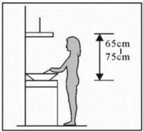
Pic1
Warning: Failure to install the screws or fixing device in accordance with these instructions may result in electrical hazards
(4) NOTICE OF INSTALLATION
- Before installation, please ensure the area is clean to avoid suction of the remaining bits of broken wood and dust.
- It cannot share the same air ventilation tube with other appliance such as gas tube, warmer tube, and hot wind tube.
- The bending of ventilation tube should be≥120°, parallel or above the start point and should be connected to the external wall.
- After installation, make sure that the extractor is level to avoid grease collection at one end.
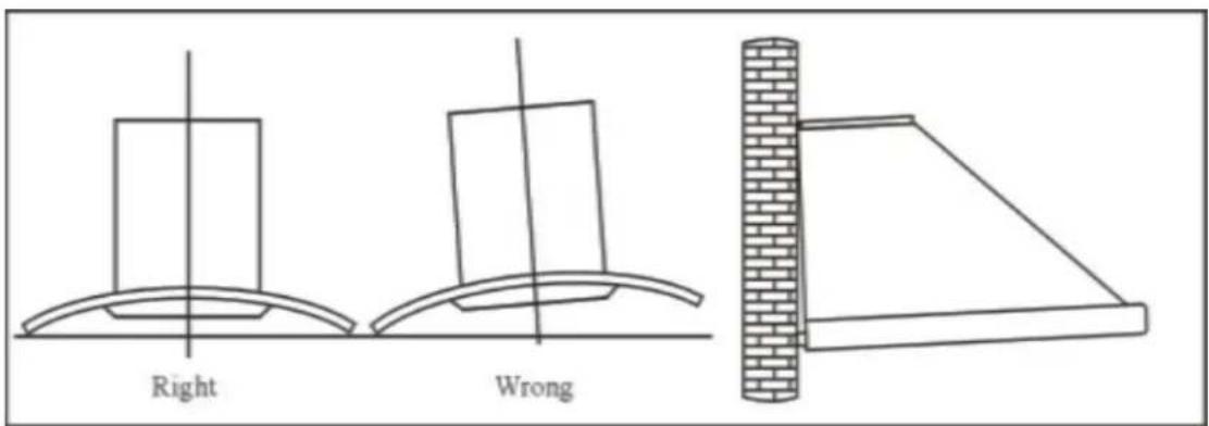
Pic5
(5) SAFETY WARNING
✧ Keep your children from using the cooker hood.
Your cooker hood is for domestic use only, not suitable for barbecue, roast shop and other commercial use.
Any installation work must be carried out by a qualified electrician or competent person.
The cooker hood and its filter mesh should be cleaned regularly in order to keep in good working order.
Before cleaning, always ensure that you have switched your cooker hood off.
Clean the cooker hood according to the instruction manual and keep the cooker hood from the danger of burning.
✦ No fire for drying your cooker hood.
If there is any fault with your cooker hood, please call the service department appointed by agent for servicing.
Please keep the room draughty when your cooker hood and gas hob are working.
Do not exhaust the gas from cooker hood through the same heated flue which is for the gas from gas hob and other kitchen appliances.
Before installation and usage, read all the instructions and make sure that the voltage (V) and the frequency (Hz) indicated on your cooker hood are exactly the same as the voltage (V) and the frequency (Hz) in your home.
In order to get the most out of your cooker hood, please read the instruction manual before installing & using, and keep it in a safe place.
- Ensure that you could get our guarantee for your cooker hood, please provide the warranty card and purchase receipt, or the guarantee will not be offered.
(6) USE
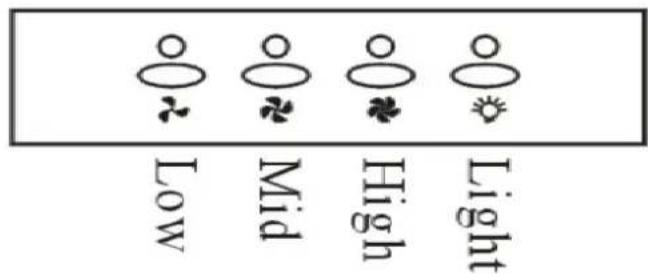
Electronic Button
- Turn on the power; the buzzer will buzz five times. The sound shows that the appliance is powered.
- Push the low button, the indicating light 1 on, the buzzer will buzz once, and the motor runs at low speed. Push it again and the motor will stop.
- Push the middle button, the indicating light 2 on, the buzzer will buzz once, and the motor runs at mid speed. Push it again and the motor will stop
- Push the high button, the indicating light 3 on, the buzzer will buzz once, and motor runs on high speed. Push it again and the motor will stop
- Push the light button; the indicating light 4 on, and the two lighting lamps will come on. Push it again and the lamps will turn off, with every push the buzzer will buzz one time.
Indicatorlight ① ② ③ ④
Pic6A
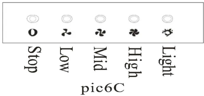
Push button
- Push stop button, and the motor will stop.
- Push the Low button, the buzzer will buzz once, and the motor runs at low speed.
- Push the Mid button, the buzzer will buzz once, and the motor runs at mid speed.
- Push the High button, the buzzer will buzz once, and the motor runs at high speed.
- Push the light button and the two lights will come on. Push it again and the light will turn off.
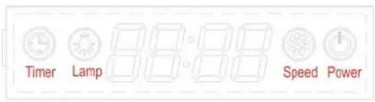
LCD Electronic button
Pic 7
-
Plug the hood; LCD will display 24-hour system with blue backlight. Backlight will be extinguished after 30 seconds without any operation.
-
Press “ ” button once; lights will be on and LCD will show “ Lamp”. Press “ ” button again; lights will be off and “ Lamp” on LCD will disappear.
-
Press “💡” button once; the hood works at LOW speed and LCD will show “Speed” and “💡” button will be on. Press “💡” button again; the hood works at MEDIUM speed. Press “💡” button one more time; the hood works at HIGH speed. Press “💡” button again; the hood works at LOW speed again and it repeat. While pressing “💡” button; the “💡” button is always on. If you want to stop the hood now; press the “💡” button once.
-
When the hood is not working; press " 🔊" button once. The hood will work at the
speed it works last time and LCD will show "Speed". Press "button again; the hood stop working and "Speed" will disappear from LCD.
- When both “ ” button and “ ” button don’t work; “ ” button is used for time-setting. Press “ ” button for 2 to 3 seconds; will be shown on LCD and flashes; which represents hour. Press “ ” button once the number adds by 01. Continue pressing “ ” button; it will display from 13;14... until 23. When LCD shows 23; it doesn’t work by pressing “ ” button. Press “ ” button once; the number reduces by 01. When LCD shows 00; it doesn’t work by pressing “ ” button. After setting hour; you can start setting minute by pressing “ ” button again. 📋 on LCD flashes; which represents minutes. Press “ ” button once the number adds by 01. Continue pressing “ ” button; it will display from 01;02... until 59. When LCD shows 59; it doesn’t work by pressing “ ” button. Press “ ”
button once; the number reduces by 01. When LCD shows 00; it doesn't work by pressing “💡” button. After setting hour and minute; press “💡” to confirm.
When “💡” button doesn’t work; “💡” button is used for delay timer function. Delay timer function allows you to set the hoods automatically power off according to the delay timer you set from 1 minute to 60 minutes. Press “💡” button once; it enters for delay timer setting and LCD shows 📋. Press “💡” button once the number
adds by 01. Continue pressing “ ” button; it will display from 1:500 66:00; 70:00... until 60:00 Press “ ” button once; the n
reduces by 01. After setting delay timer you want; press “💡” button to confirm. If you set delay timer as 05:00; the LCD display will show from 05:00; 04:59... until 00:01 00:00. When LCD shows 00:00; the hood will automatically power off and LCD display will only show 24-hour system with blue backlight. After 30 seconds without operation; blue backlight will disappear. But please note the Lamp is not under control of delay timer. Next time; if you want to use delay timer function and you press “💡” button without any change on time. The hood will automatically count time down from your previous setting after 5 seconds.
LCD Touch control

Pic 8
-
Power on: Switch on the power supply, and the backlight is lit, displaying "24-hour system". The output is then blocked up, and the soot machine enters standby status. The backlight disappear automatically 30 seconds later under the condition of none operation.
-
Press "Indicator" key: Press the indicator key once, the indicator is lit, and Ⓐ on the LCD screen is lit. Press it for a second time, Ⓐ of the indicator and the LCD screen will distinguish and it will be repeated again and again.
-
Power on position and increase key +, the motor is provided with three positions, i.e. low, medium and high.
-
Press + key once, the ■ displayed on the display screen, and the motor starts operation. The ■ is the low position (power on position.)
-
Press + key once more at the low position, the ■ is played on the display screen, and the ■ is the medium position.
-
Press + key once more at the medium position, the □ □ □ played on the display screen, and the □ □ □ is the high position.
-
Go on pressing + key at the high position, the ■ displayed on the display screen, and the motor works normally. It is still at high position at this time.
-
Power on position and decrease key “—”
-
Press “—” key once, the motor is adjusted to a lower position, and the LCD screen displays that position in the meantime; If it is decreased continuously to none position, then, it is the power off position (namely, the motor stops operation.)
-
Timer key “○”:
-
The timer key is the timer setting key if the timer key doesn't work at both the position and indicator.
Long press timer key ⬆ for 2-3 seconds, time segment 88:88 and the first two hour bit segment flash, use +key for the digit increase, and use —key for the digit decrease. Namely: The variable is 01 each time it is pressed; the hour segment is with the largest digit of 23. If it exceeds 23,
+ key is null and void. If it is equal to 00, then, the -key is null and void.
Press the timer key for the 2^nd time Time segment, and the last two minute bit segment flash, use + key for the digit increase, and use - key for the digit decrease. Namely: The variable is 01 each time it is pressed; the minute segment is with the largest digit of 59. If it exceeds 59, + key is null and void. If it is equal to 00, then, the - key is null and void.
Press the timer key Ⓧ for the 3 ^rd time, and it is the time setting exit and confirm key.
Long press timer key ⚙ for 2-3 seconds under this operation mode, and it is for the hour setting; Press it for the 2^nd time: Setting for the minute; Press it for the 3^rd time: For the time setting exit and confirm, and it will be repeated again and again (if the 1^st time pressing doesn't exceed 2 seconds, then it can't run this operating procedure.)
- The timer key is the timer if the timer key works at either the position or the indicator.
It is provided with three kinds of time segment, and they are 5min/15min/30min/timer cancel in sequence, and the 1^st time is 5min, the 2^nd time is 15min, the 3^rd time is 30min, the 4^th time is timer cancel, the 5^th time is 5min, and the 6^th time is 15min ..., and it will be repeated again and again.
Example: Let the setting time be 15min, the display is 00:15, 00:14, ...00:1, with 0:00 displays per minute, and once "00:00" appears, the motor position and the indicator power supply will be cut off automatically, (the display screen displays "24-hour system", the output is blocked up, and the soot machine enters standby status, and the backlight will be put out automatically 30 seconds later.)
☐ Time segment change over, 5 seconds later, it starts to decrease gradually (example: 15min is changed over to 30min, with a delay of 5 seconds, and 00: 30 on the display screen starts to decrease gradually).
(7) MAINTENANCE
7.1 The cleaning of the carbon grease filter mesh
The filter mesh is made of high-density stainless steel. Please do not use the corrosive detergent on it. Keeping this filter clean will keep the appliance running correctly. Please strictly follow the guidelines below.
Method 1: Put the mesh into 40-50 c clean water, pour on detergent, and soak for 2-3 mins. Wear gloves and clean with a soft brush. Please do not apply too much pressure, as the mesh is delicate and will damage easy.
Method 2: If instructed to do so, it can be put into a dishwasher, set the temperature at around 60 degrees.
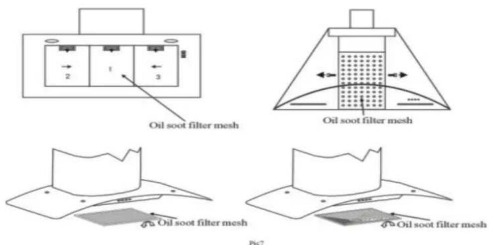
7.2 Notice of cleaning cooker hood
A. To protect the main body from corrosion over a long period of time, the cooker hood should be cleaned with hot water plus non corrosive detergent once a month. The hood should be wiped off with dry clean cloth after cleaning is done.
B. Please do not use abrasive detergent for it will damage the body.
C. Keep the motor and other spare parts free from water, as this will cause damage to the appliance.
D. Before cleaning the appliance please remember to turn off power
E. The carbon filter shouldn't be exposed to heat.
F. Please don't tear open the fixed bar around the carbon filter
G. If the supply cord is damaged, it must be replaced by the manufacturer, its service agent or similarly qualified persons in order to avoid a hazard.
(8) LIGHT REPLACEMENT
8.1 Halogen lighting:
Use a small flat blade screwdriver to remove the inner stainless steel ring (when removing the inner ring, do so carefully so not to damage the range hood, as the glass lens could easily fall out of the inner ring); and remove carefully the halogen globe with a new one.
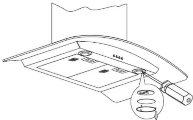
8.2 LED lighting:
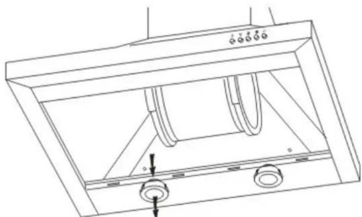
NOTE: Power needs to be disconnected for replacement of LED lights as access is required to loosen the cord restraints to undergo this procedure. The LED lamp assembly should be ordered directly from the supplier of the canopy hood.
Remove the filters, and push the light downwards, and unplug the wiring connector. Reverse the procedure to place the new light assembly into position.
natural_image
Technical line drawing of a ceiling-mounted appliance with two curved pipes and mounting holes (no text or symbols)(9) Abnormity and Solution
| Fault | Cause | Solution | |
| Light on, but motor does not work | The leaf blocked Get rid of the blocking | ||
| The capacitor damaged Replace capacitor | |||
| The motor jammed bearing damaged | Replace motor | ||
| The internal with of motor off or a bad smell from the motor | Replace motor | ||
| Light does not work, motor does not work | Beside the above mentioned, check the following: | ||
| Light damaged Replace lights | |||
| Power cord looses Connect the wires as per the electric diagram | |||
| Oil leakage | One way valve and the air ventilation entrance are not tightly sealed | Take down the one way valve and seal with glue | |
| Leakage from the connection of U-shaped section and cover | Take U-shaped section down and seal with soap or paint | ||
| Shake of the body The | leaf damaged and causes shaking | Replace the leaf | |
| The motor is not tightly hanged | Lock the motor tightly | ||
| The body is not tightly hanged | Fixed the body tightly | ||
| Insufficient suction The | distance between the body and the gas top too long | Readjust the distance | |
| Too much ventilation from open doors or windows | Choose a new place and resemble the machine | ||
| The machine inclines The | fixing screw not tight enough | Tighten the hanging screw and make it horizontal | |
| The hanging screw not tight enough | Tighten the hanging screw and make it horizontal | ||
PRODUCT SERVICE NUMBER
1800 805 300
WEB - customersupport@hapl.com.au

HOME APPLIANCES
distributors of
Euromaid

IAG
FAGOR

- 600mm Curved Glass & Stainless Steel Canopy
- HOME APPLIANCES
- CONTENT
- NOTICE
- SAFETY WARNINGS
- (2)FEATURE
- (3). Installation
- If the model without Glass:
- If the model with Glass:
- NOTICE OF INSTALLATION
- SAFETY WARNING
- USE
- Electronic Button
- Push button
- LCD Electronic button
- Pic 7
- LCD Touch control
- MAINTENANCE
- The cleaning of the carbon grease filter mesh
- Notice of cleaning cooker hood
- LIGHT REPLACEMENT
- Halogen lighting:
- LED lighting:
- PRODUCT SERVICE NUMBER
- 805 300
Brand : Euromaid
Model : CG6BLS
Category : Range hood