
GDL 82 - Receiver GARMIN - Free user manual and instructions
Find the device manual for free GDL 82 GARMIN in PDF.


| Product Type | Remote-Mounted Universal Access Transceiver (UAT) for ADS-B Out |
| Model | GDL 82 (with internal GPS/SBAS receiver option) |
| Brand | Garmin |
| Part Numbers | 011-03946-40 (with GPS), other variants available |
| Software Versions | System SW v2.00, FPGA v2.3, Internal GPS SW v6.0 (as of Rev. 2) |
| Transmitter Frequencies | 978 MHz (UAT) and 1030 MHz (interrogation), 1090 MHz receiver |
| Power Input | 15V DC via 15-pin D-sub connector, circuit protected |
| Power Consumption | Refer to Electrical Load Analysis; typical max current draw per installation |
| Interfaces | Coaxial (transponder, L-Band, GPS), RS-232, USB, discrete I/O for annunciator and switches |
| GPS Source | Internal GPS/SBAS or external (GNS/GTN/ADS-B+ Format 2) |
| ADS-B Out Compliance | 14 CFR Part 91.227, transmits ownership data via UAT |
| Installation | Remote mount, in-line with existing transponder and L-Band antenna |
| Maintenance Intervals | Visual inspection every 12 calendar months; electrical bonding check every 2000 flight hours or 10 years |
| On-Condition Servicing | Only when symptoms or faults appear; no component-level overhaul required |
| Special Tools Required | GDL 8X Install Tool on Windows PC, calibrated milliohm meter, transponder ramp test set, optional ADS-B test set |
| Annunciator | Optional ADS-B OUT FAIL annunciator, push-to-test |
| Anonymous Mode | Optional switch to enable anonymity feature |
| Regulatory Approvals | FAA STC SA02573SE for Mooney M20 series; compliant with 14 CFR Parts 23, 43, 91 |
| Environmental | Operates in typical aircraft environment; bonding required to < 2.5 mΩ to aircraft ground |
Frequently Asked Questions - GDL 82 GARMIN
User questions about GDL 82 GARMIN
0 question about this device. Answer the ones you know or ask your own.
Ask a new question about this device
Download the instructions for your Receiver in PDF format for free! Find your manual GDL 82 - GARMIN and take your electronic device back in hand. On this page are published all the documents necessary for the use of your device. GDL 82 by GARMIN.
USER MANUAL GDL 82 GARMIN
Instructions for Continued Airworthiness & Maintenance Manual,
GDL 82 Mooney M20( ) Series STC
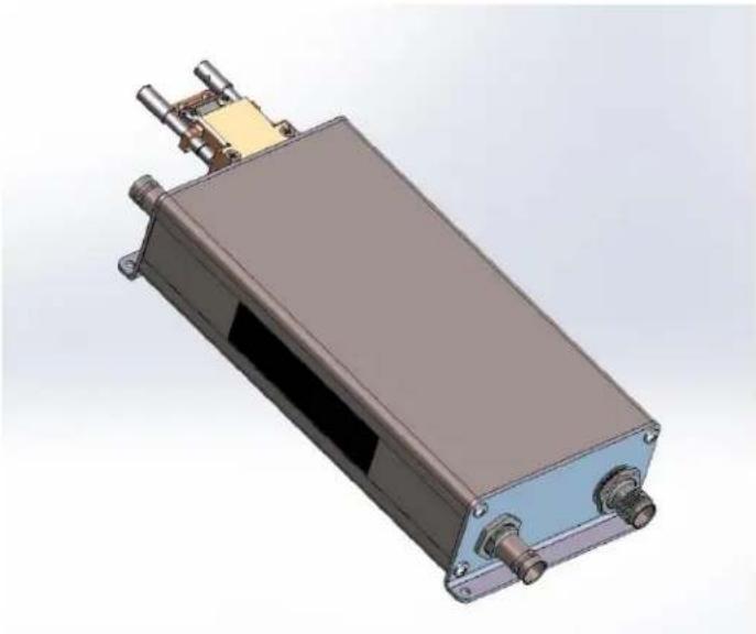
natural_image
3D rendering of a rectangular electronic device with mounting flanges and a small metallic component attached (no text or symbols visible)Aircraft make, model, registration number, and serial number and accompanying STC configuration information in Appendix A must be completed and retained with aircraft permanent records.
©2019 Garmin International or its subsidiaries All Rights Reserved
Except as expressly provided herein, no part of this manual may be reproduced, copied, transmitted, disseminated, downloaded or stored in any storage medium, for any purpose without the express prior written consent of Garmin. Garmin hereby grants permission to download a single copy of this manual and of any revision to this manual onto a hard drive or other electronic storage medium to be viewed and to print one copy of this manual or of any revision hereto, provided such electronic or printed copy of this manual or revision must contain the complete text of this copyright notice and provided further any unauthorized commercial distribution of this manual or any revision hereto is strictly prohibited.
Garmin®, flyGarmin®, and GDL® are registered trademarks of Garmin International or its subsidiaries. The GDL 82™ and GTN™ are trademarks of Garmin International or its subsidiaries. These trademarks may not be used without the express permission of Garmin.
Windows® is a registered trademark of Microsoft Corporation in the United States and other countries.
All other product or company names that may be mentioned in this publication are trade names, trademarks, or registered trademarks of their respective owners.
At Garmin, we value your opinion. For comments about this guide please e-mail: Techpubs.Salem@garmin.com.
For information regarding the Aviation Limited Warranty, refer to Garmin's website.
Garmin International, Inc.
1200 E. 151st Street
Olathe, KS 66062 USA
Telephone: (913) 397-8200
Aviation Dealer Technical Support Line (Toll Free): (828) 606-5482
www.garmin.com
www.flyGarmin.com
Garmin AT, Inc.
2345 Turner Rd. SE
Salem, OR 97302 USA
Telephone: (503) 581-8101
RECORD OF REVISIONS
| Revision | Revision Date | Description |
| 1 | 12/14/2017 | Initial Release |
| 2 | 09/23/2019 | Update to add GPS 175/GNC 355 as GPS sources, and to update main board and GPS/GBAS board software versions (non-functional) |
GARMIN®
INFORMATION SUBJECT TO EXPORT CONTROL LAWS
This document may contain information which is subject to the Export Administration Regulations (“EAR”) issued by the United States Department of Commerce (15 CFR, Chapter VII, Subchapter C) and which may not be exported, released, or disclosed to foreign nationals inside or outside of the United States without first obtaining an export license. A violation of the EAR may be subject to a penalty of up to 10 years imprisonment and a fine of up to \$1,000,000 under Section 2410 of the Export Administration Act of 1979. Include this notice with any reproduced portion of this document.
DEFINITIONS OF WARNINGS, CAUTIONS, AND NOTES

WARNING
Warnings indicates that personal injury or death is possible if the instructions are not obeyed.

CAUTION
Cautions are used to alert that damage to equipment may result if the procedural step is not followed.

NOTE
Notes provide further information about preceding steps and/or reasons for the particular operation.

WARNING
This product, its packaging, and its components contain chemicals known to the State of California to cause cancer, birth defects, or reproductive harm. This notice is being provided in accordance with California's Proposition 65. If you have any questions or would like additional information, please refer to our web site at www.garmin.com/prop65.

NOTE
All screen shots used in this document are current at the time of publication. Screen shots are intended to provide visual reference only. All information depicted in screen shots, including software file names, versions, and part numbers, is subject to change and may not be up to date.
GARMIN®
TABLE OF CONTENTS
SECTION ...... PAGE
1 INTRODUCTION....1
1.1 Introduction....1
1.2 Organization....1
1.3 Acronyms and Abbreviations .... 1
1.4 Publications....2
1.5 Revision and Distribution 2
2 SYSTEM DESCRIPTION....3
3 CONTROL & OPERATION....4
3.1 GDL 82 Install Tool....4
4 INSTRUCTIONS FOR CONTINUED AIRWORTHINESS....8
4.1 Airworthiness Limitations 8
4.2 Servicing Information 8
4.3 Maintenance Intervals....9
4.4 Visual Inspection 10
4.5 Electrical Bonding Test....11
5 TROUBLESHOOTING 12
5.1 General....12
5.2 ADS-B OUT FAIL Annunciator 14
5.3 GDL 82 Install Tool....14
5.4 GDL 82 Data Logging 16
5.5 GDL 82 Connector Pinout .... 17
6 EQUIPMENT REMOVAL & INSTALLATION 18
6.1 GDL 82 Unit....18
6.2 Annunciator and Switch....18
6.3 GPS Antenna....19
6.4 Transponder Antenna....19
7 EQUIPMENT CONFIGURATION & CHECKOUT....20
7.1 System Checkout 20
7.2 GDL 82 Configuration....20
7.3 GDL 82 Post-Installation Test Procedures....21
8 RETURN TO SERVICE PROCEDURE....21
8.1 Maintenance Records....21
GARMIN®
FIGURES
FIGURE PAGE
Figure 2-1: GDL 82 System I/O Interfaces....3
Figure 3-1: USB A and USB B Connectors....4
Figure 3-2: GDL 8X Install Tool Selection .... 4
Figure 3-3: GDL 82 Unit Information Page....5
Figure 3-4: GDL 82 Software Upload Page....6
Figure 3-5: GDL 82 System Configuration Page....7
Figure 5-1: GDL 82 Install Tool, Faults Page 15
Figure 5-2: GDL 82 Install Tool, GPS Page....15
Figure 5-3: GDL 82 Install Tool, GPS Sat Status Page....16
Figure 5-4: GDL 82 Install Tool, Assert Log Page....16
Figure 5-5: Rear View, Connector J821 .... 17
TABLES
TABLE PAGE
Table 1-1: Recommended Documents....2
Table 4-1: Maintenance Intervals ......9
Table 5-1: General Troubleshooting Guide .... 12
Table 5-2: System Faults Troubleshooting Guide ...... 13
Table 5-3: J821 Pinout....17
GARMIN
1 INTRODUCTION
1.1 Introduction
This document provides Instructions for Continued Airworthiness (ICA) and Maintenance Manual (MM) for the Garmin GDL 82 UAT Transmitter as installed in Mooney M20() Series aircraft under STC SA02573SE. This document satisfies the requirements for continued airworthiness as defined by 14 CFR Part 23.1529 and Appendix G. Information in this document is required to maintain the continued airworthiness of the GDL 82.
1.2 Organization
The following outline briefly describes the organization of this manual:
Section 2: System Description
Provides a complete description of the type design change associated with installing the GDL 82. An overview of the system interface is also provided.
Section 3: Control & Operation
Presents basic control and operation information related to maintenance of the GDL 82.
Section 4: Instructions for Continued Airworthiness
Provides maintenance instructions for continued airworthiness of the GDL 82.
Section 5: Troubleshooting
Provides troubleshooting information to aid in diagnosing and resolving potential problems with the GDL 82.
Section 6: Equipment Removal & Installation
Contains instructions for the removal and installation of the GDL 82.
Section 7: Equipment Configuration & Checkout
Contains instructions for configuring and testing the GDL 82 after reinstallation or replacement.
Section 8: Return to Service Procedure
Specifies return-to-service procedures required after completion of the GDL 82 maintenance.
Appendix A: Installation Specific Information
Provides a template to record general installation information and the system configuration log for a specific installation of the GDL 82.
1.3 Acronyms and Abbreviations
The following acronyms are used in this manual:
| AC | Advisory Circular | ICA | Instructions for Continued Airworthiness |
| ADS-B | Automatic Dependent Surveillance – Broadcast | ICAO | International Civil Aviation Organization |
| AFM | Airplane Flight Manual | I/O | Input / Output |
| AFMS | Airplane Flight Manual Supplement | IM | Installation Manual |
| ALT | Altitude | MM | Maintenance Manual |
| ATC | Air Traffic Control | PC | Personal Computer |
| CFR | Code of Federal Regulations | POH | Pilot Operating Handbook |
| DC | Direct Current | SBAS | Satellite-Based Augmentation System |
ICA/MM, GDL 82 Mooney M20() Series STC 190-01810-11
Rev. 2
GARMIN®
| ELA | Electrical Load Analysis | STC | Supplemental Type Certificate |
| EMC | Electromagnetic Checkout | SW | Software |
| FAA | Federal Aviation Administration | UAT | Universal Access Transceiver |
| GDL | Garmin Datalink Transceiver | USB | Universal Serial Bus |
| GNS | Garmin Navigator Series | Vs0 | Aircraft Stall Speed (in landing configuration) |
| GPS | Global Positioning System | XPDR | Transponder |
| GTN | Garmin Touch Navigator |
1.4 Publications
When performing GDL 82 system maintenance it is recommended the following documents are available.
Table 1-1: Recommended Documents
| Part Number | Garmin Document |
| 190-01810-03 | GDL 82 Pilot's Quick Start Guide |
| 190-01810-10 | GDL 82 Mooney M20() Series STC Installation Manual |
| 190-01810-12 | Airplane Flight Manual Supplement for the GDL 82 Mooney M20 Series |
1.5 Revision and Distribution
This document is required for maintaining the continued airworthiness of the aircraft. When this document is revised, every page will be revised to indicate current revision level.
Owner/operators may obtain the latest revision of this document at www.flyGarmin.com or by contacting a Garmin dealer. Garmin contact information is available at www.flyGarmin.com.
GARMIN
2 SYSTEM DESCRIPTION
The GDL 82 is a remote-mounted unit that contains 978 MHz and 1030 MHz transmitters, and a 1090 MHz receiver. It is installed in-line with the existing transponder and L-Band antenna. The GDL 82 transmits ownership ADS-B Out data via the UAT data link using the existing transponder's L-Band antenna. The GDL 82 utilizes the direct in-line connection to synchronize with the aircraft transponder via 1030 MHz interrogations to obtain the transponder Squawk (Mode 3/A) code, IDENT status and pressure altitude.
ADS-B equipment requires GPS/SBAS data for ADS-B Out transmissions. Only the GPS/SBAS data sources specified in the GDL 82 Mooney M20() Series STC Installation Manual, 190-01810-10, are approved by this STC to interface with the GDL 82.
The GDL 82 uses the following interfaces:
- Aircraft Power and Ground
• Transponder Coaxial Connection
• L-Band Coaxial Connection
• GPS Coaxial Connection – Used only for internal GPS source
• 1 RS-232 I/O – Used only for external GPS source
• 1 Discrete Output – Failure Annunciator (optional)
• 2 Discrete Inputs – Anonymous Mode Switch and Squat Switch (optional)
• USB Interface – Configuring GDL 82 and Loading Software from PC
The GDL 82 System Interface Diagram is shown in Figure 2-1.
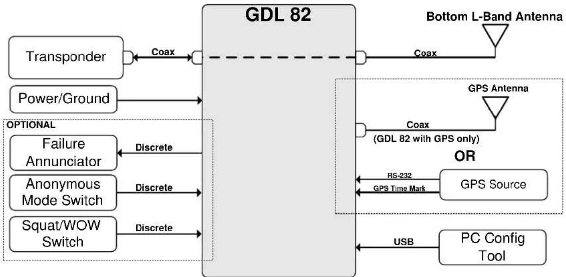
flowchart
graph LR
    A["Transponder"] -->|Coax| B["GDL 82"]
    C["Power/Ground"] --> B
    D["Optional"] -->|Discrete| B
    E["Failure Annunciator"] -->|Discrete| B
    F["Anonymous Mode Switch"] -->|Discrete| B
    G["Squat/WOW Switch"] -->|Discrete| B
    H["Bottom L-Band Antenna"] -->|Coax| I["GDL 82 with GPS only"]
    J["GPS Antenna"] -->|Coax| I
    I --> K["GPS Source"]
    I --> L["RS-232 GPS Time Mark"]
    M["PC Config Tool"] -->|USB| L
Figure 2-1: GDL 82 System I/O Interfaces
GARMIN®
The GDL 82 user control interface is limited to ADS-B OUT FAIL annunciator and the UAT ANONYMOUS mode switch, installation of either or both is optional. The primary ADS-B Out UAT transmit function of the GDL 82 does not require direct user input.
Refer to the GDL 82 Pilot's Quick Start Guide, 190-01810-03, and the Airplane Flight Manual Supplement for the GDL 82 Mooney M20 Series, 190-01810-12, for control and operation information.
3.1 GDL 82 Install Tool
The GDL 8X Install Tool (Garmin Part Number: 006-A0248-20) allows for configuration, diagnostics, and software loading. The tool is available for download from the Garmin Dealer Resource Center and flyGarmin.com. The GDL 8X Install Tool requires a computer with Microsoft Windows XP or later and an available USB 2.0 port.
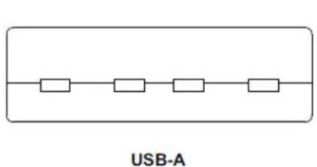
A USB A-to-B cable is required to interface between a computer and the GDL 82, refer to Figure 3-1 for details.
natural_image
Pure electrical circuit lines without any symbols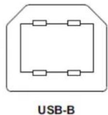
natural_image
Pure electrical circuit lines without any symbolsFigure 3-1: USB A and USB B Connectors
The GDL 82 Install Tool provides access to the following functions -
- Diagnostics – reports device information, faults, interface status and other information for post installation checkout procedures. It also allows the unit assert log to be saved and cleared.
- Configuration – allows selection of installation options.
- System Update – allows upload of software to the GDL 82 unit.
To utilize the GDL 82 Install Tool, first disconnect power from the GDL 82, and then connect the USB cable. Restore power to the GDL 82, and then run the GDL 8X Install Tool.
The GDL 8X Install Tool will automatically detect which unit it is interfaced with (e.g., GDL 82 or GDL 84/88). To use the GDL 82 Install Tool verify that the GDL 82 unit is checked Present and select the GDL 82 button. See Figure 3-2.
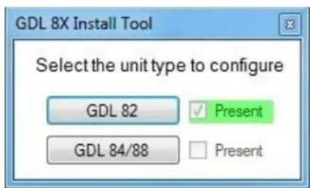
Figure 3-2: GDL 8X Install Tool Selection
GARMIN®

NOTE
When the GDL 82 unit is connected to the PC (via USB) and the GDL 8X Install Tool is active, the GDL 82 will automatically be placed in Configuration Mode. To reset the GDL 82 into Normal Mode, power down the unit, disconnect it from the USB and reapply power to the GDL 82.
3.1.1 Device Information
The Unit Information page, displays product information such as the model, part number, serial numbers, software version and software part numbers to be viewed.
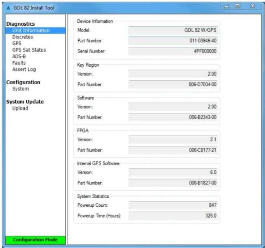
Figure 3-3: GDL 82 Unit Information Page
The other Diagnostics pages are used during post-installation checkout and troubleshooting. See Section 5.3 for details.
GARMIN®
3.1.2 Software Loading
This section contains instructions for loading GDL 82 software using the GDL 82 Install Tool. The GDL 82 comes preloaded with software. However, it is necessary to verify the software version and part numbers. The System Update / Upload page, shown in Figure 3-4, displays the version and part number of the GDL 82 System Software, FPGA, and GPS Software.

NOTE
Verify the installed software version in accordance with the GDL 82 Mooney M20() Series STC Installation Manual, 190-01810-10.
The GDL 82 software is available at the Garmin Dealer Resource Center and flyGarmin.com.
Software may be loaded by performing the following steps on the Upload page:
- Download the latest GDL 82 software from the Garmin Dealer Resource Center or flyGarmin.com.
- Under Step 1 – Select a File, select the Browse key and locate the file containing the GDL 82 software previously downloaded in step 1.
- Under Step 2 - Upload Options, select the options to be loaded (i.e., System, FPGA, and/or GPS).
- Under Step 3 - Start Upload, select the Upload Software key.
- After successful completion, return to the Diagnostics / Unit Information page and verify the software version and part numbers are correct.
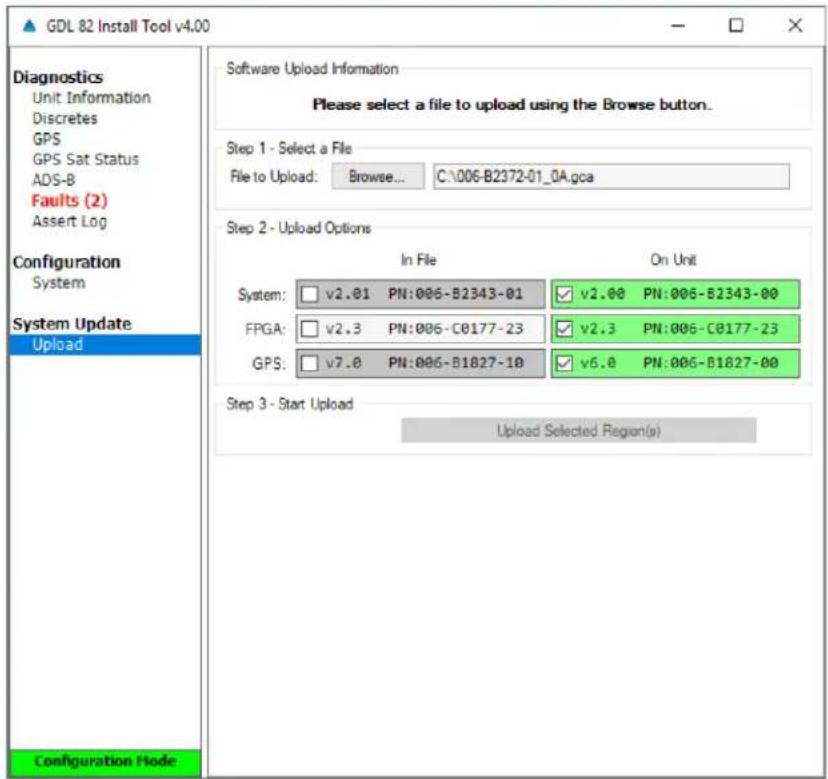
Figure 3-4: GDL 82 Software Upload Page
GARMIN®
3.1.3 Configuration
The GDL 82 Install Tool is used to configure the GDL 82 settings. All configurable settings must match the GDL 82 System Configuration Log retained in the aircraft permanent records.
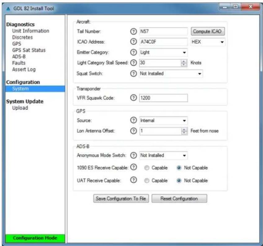
Figure 3-5: GDL 82 System Configuration Page
GARMIN®
4 INSTRUCTIONS FOR CONTINUED AIRWORTHINESS
This section provides Instructions for Continued Airworthiness of the GDL 82 system as installed under STC SA02573SE and satisfies the requirements for continued airworthiness as defined by 14 CFR Part 23.1529 and Part 23 Appendix G.
4.1 Airworthiness Limitations
The Airworthiness Limitations section is FAA-approved and specifies maintenance required under §43.16 and §91.403 of the Federal Aviation Regulations unless an alternative program has been FAA-approved.
There are no new (or additional) airworthiness limitations associated with this equipment and/or installation.
FAA APPROVED
Cilk-Jmik
Erik Frisk
ODA STC Unit Administrator
ODA-240087-CE
23-SEP-2019
Date
4.2 Servicing Information
The GDL 82 unit maintenance is ‘on condition’ only. See Section 6 for equipment removal and installation. No component-level overhaul is required.
4.2.1 On-Condition Servicing
On Condition replacement and/or servicing maybe required when conditions, symptoms, and/or abnormalities as defined in Section 5 of this manual are exhibited. Replacement and/or servicing should take place only after the system is troubleshoot based on guidance provided in this manual and common avionics maintenance practices.
4.2.2 Special Tools
The following tools are needed to perform maintenance tasks.
• Ground power source (capable of supplying sufficient power to the aircraft systems and avionics).
- A calibrated milliohm meter with a precision of ± 0.1 m , or better, to measure the electrical bonding between system components and aircraft ground.
- A calibrated ammeter with a precision of ±0.5 amps and a current capacity sufficient for the total aircraft load for the ELA.
• A calibrated Transponder Ramp Test Set (e.g., Aeroflex IFR-6000 or TIC TR-220).
- If the transponder ramp test set is not capable of receiving UAT (978MHz) ADS-B Out messages, an additional ADS-B Test Set (e.g., Garmin GDL 39(R/3D)/52 and Garmin Pilot application on iOS device)
• GDL 82 Install Tool (with PC)
4.3 Maintenance Intervals
Periodic checks of the GDL 82 system installed by STC SA02573SE are specified in Table 4-1 at specific intervals.
Table 4-1: Maintenance Intervals
| Item | Description/Procedure | Section No. | Interval |
| EquipmentRemoval and Replacement | Removal & Reinstallation of the following items:GDL 82 unitADS-B OUT FAILAnnunciatorAnonymous Mode Switch | 6 | On Condition |
| Equipment Visual Inspection | Conduct a visual check of the GDL 82 unit, and associated wire harness to ensure continued installation integrity. | 4.4 | 12 Calendar Months |
| Lightning Strike – Actual or Suspected | Inspect the coaxial cable connections, GDL 82 bonding hardware, antenna(s) and surrounding areas. | 4.4 | On Condition |
| The interfacing transponder transmit power and receiver sensitivity must be tested and shown to comply with Title 14 CFR Part 43 Appendix F. | 7.3 | On Condition | |
| Testing | The GDL 82 must be tested and shown to comply with Title 14 CFR Part 91.227. | 7.3 | Installation, software update or replacement of GDL 82 [1]. |
| Testing | The interfacing transponder and altimeter/altitude reporting system must be tested and shown to comply with Title 14 CFR Part 91.411, 91.413, and Part 43 Appendix E and F. | 7.3 | In accordance with Title 14 CFR Part 91.411, 91.413, and Part 43 Appendix E and F. |
| Electrical Bonding Check | Perform an electrical bonding check of the GDL 82. | 4.5 | Every 2000 Flight hours or ten (10) years, whichever comes first. |
[1] This interval condition includes the installation or replacement of the GPS antenna for the GDL 82 with GPS/SBAS receiver.
GARMIN
4.4 Visual Inspection
Perform a visual inspection as detailed in this section. Check GDL 82 system components for damage or other defects and replace as required. Inspection may require the temporary removal of a unit to gain access to connectors. Follow guidance in Section 6 for equipment removal and replacement. Refer to Appendix A of this manual for equipment locations. Refer to model specific Aircraft Maintenance Manual for instructions on removing access panels or covers.
4.4.1 GDL 82 Visual Inspection
- Inspect the GDL 82 unit and verify it is securely mounted.
- Inspect unit fasteners and verify they are properly torqued and show no wear or damage. Additionally -
a. Verify unit support structure is in good condition and its integrity is not compromised.
b. Inspect for corrosion and treat as required following procedures prescribed in Aircraft Maintenance Manual.
- Inspect any bonding straps for corrosion, loose connections, or signs of damage.
- Inspect the condition of the wiring harness and coaxial cables.
a. Verify that all wiring and cables are securely fastened.
b. Verify that the harness shows no signs of cracking, chafing, abrasion, melting, or any other form of damage.
c. Inspect the GDL 82 connectors for corrosion, evidence of moisture, or other defects. Check the integrity of the shield block ground attachments to the harness connector assembly as well as the integrity of the individual shields and their attachment.
- If installed, inspect the ADS-B OUT FAIL annunciator and UAT Anonymous Mode switch.
a. Verify that annunciator and/or switch show no signs of damage.
b. Verify that wiring is securely fastened.
c. Inspect the labels, that they are legible and properly adhered.
d. Confirm operation of UAT anonymous mode switch and ADS-B OUT FAIL annunciator. To check the UAT anonymous mode switch is operational, connect the laptop with installation tool to the GDL 82 and verify the change of discrete state for the anonymous mode switch.
4.4.2 Antenna Visual Inspection
- Clean the antenna with water and mild soap.
- Verify there are no cracks on the antenna body and around the antenna fasteners. If the antenna has cracks, dents, or is otherwise broken, it must be replaced. Refer to antenna manufacturer's replacement instructions for details.
- Verify the integrity of the environmental seal around the antenna base. If the antenna seal is damaged, re-seal and complete the electrical bonding test specified in Section 4.5.
4.4.3 Post Lightning Strike Inspection
Inspection of antennas connected to the GDL 82 unit must be performed following a suspected or actual lightning strike. Antenna and nearby aircraft structure must be inspected to verify no damage has occurred where lightning may have attached. Antenna with visible signs of damage should be replaced.
GARMIN®
Antenna coax connection to the GDL 82 unit, grounding hardware, bonding straps, and nearby aircraft structure supporting installation of remotely mounted GDL 82 must be inspected for damage. Repair any damaged components, then complete the electrical bonding test specified in Section 4.5.
4.5 Electrical Bonding Test
GDL 82 Unit
- Disconnect the antenna coaxial cables from the GDL 82.
- Disconnect all connectors from the GDL 82.
- Measure the DC resistance between the GDL 82 unit and the aircraft ground reference.
a. Verify the resistance is less than or equal to 2.5 milliohms in accordance with GDL 82 Mooney M20() Series STC Installation Manual, 190-01810-10, Section 4.
- If the bonding check fails, perform the following procedures for preparation of aluminum surfaces.
a. Clean grounding location with solvent.
b. Remove non-conductive films or coatings from the grounding location.
c. Apply a chemical conversion coat such as Alodine 1200 to the bare metal.
d. Once the chemical conversion coat is dry, clean the area.
e. Install bonding equipment at grounding location.
f. After the bond is complete, reapply a suitable film or coating to the surrounding area, if any films or coatings were removed from the surface.
For more detail on preparing aluminum surfaces, refer to SAE ARP1870 Sections 5.1 and 5.5.
Antenna
- Disconnect the coaxial cables from the antenna connector.
- Measure the DC resistance between the antenna connector body and the aircraft ground reference.
a. Verify the resistance is less than or equal to 2.5 milliohms.
- If the bonding check fails, perform the following procedures for preparation of aluminum surfaces.
a. Clean grounding location with solvent.
b. Remove non-conductive films or coatings from the grounding location.
c. Apply a chemical conversion coat such as Alodine 1200 to the bare metal.
d. Once the chemical conversion coat is dry, clean the area.
e. Install bonding equipment at grounding location.
f. After the bond is complete, reapply a suitable film or coating to the surrounding area, if any films or coatings were removed from the surface.
For more detail on preparing aluminum surfaces, refer to SAE ARP1870 Sections 5.1 and 5.5.
5 TROUBLESHOOTING
5.1 General
This section provides information to assist troubleshooting if problems occur after completing maintenance. Refer to the GDL 82 Configuration and Checkout Log retained in the aircraft permanent maintenance records for a list of the interfaced equipment and system configuration data. When troubleshooting the GDL 82, refer to the wire routing drawings and interconnect wiring diagrams that are retained in the aircraft permanent records.
The following tables describe possible symptoms associated with the Garmin GDL 82 and provides corresponding actions for troubleshooting. The symptoms described in the Problems column may be possible causes of the ADS-B OUT FAIL lamp being illuminated. After completing each corrective action, perform the appropriate return to service procedure in accordance with Section 8. If any system fault persists after performing the associated troubleshooting actions, return the GDL 82 to Garmin for service. See Section 6 for details.
Table 5-1: General Troubleshooting Guide
| Problem | Possible Cause(s) | Corrective Action |
The GDL 8X Install Tool does not indicate the GDL 82 as Present (i.e., the GDL 8X Install Tool will not connect to the GDL 82 unit).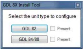 | GDL 82 is not receiving powerImproper wiringCircuit breaker open | Ensure the XPDR/UAT circuit breaker is closed.Ensure the GDL 82 connector is securely mated to the GDL 82 unit.Ensure the GDL 82 is connected to the PC via USB cable.Ensure the GDL 82 wiring is correct. |
| Poor Interfacing Transponder Performance.(i.e., transponder does not pass Title 14 CFR Part 43 Appendix F, RF Peak Output Power and Receiver Sensitivity levels.) | GDL 82 is not receiving powerDue to the nature of antenna radiation patterns, nulls or marginal conditions may be observed when measuring a utilized radiated signal from the aircraft.Transponder antenna is damaged or improperly installed.Coaxial cable has too high insertion loss.Coaxial connectors are improperly installed or damaged.Transponder requires service | Ensure the XPDR/UAT circuit breaker is closed.Ensure the GDL 82 connector is sealed and mated to the GDL 82 unit.Ensure the GDL 82 wiring is correct.Check and verify integrity of the antenna installation, ground planes, and coaxial cable.Check for proper electrical bonding/grounding of the antenna installation.Ensure the coaxial cable is properly rated (e.g., RG-400 or better) for the length of run with the GDL 82 insertion loss accounted for (see GDL 82 Mooney STC IM, 190-01810-10, Sec. 3.3, for details) |
Table 5-2: System Faults Troubleshooting Guide
| Problem | Possible Cause | Corrective Action |
| Position (GPS) Input Fault | The GDL 82 is not receiving GPS position from its internal GPS/SBAS engine. | Verify the following in the Diagnostics / GPS page of the GDL 82 Install Tool (ref. Section 5.3):Source: InternalTime Mark: Active (green box)Interface Status: Receiving (green box)Check the integrity of the GPS antenna installation, connections, and coaxial cable condition.Ensure GPS antenna has a clear, unobstructed view of the sky.Wait approximately 20 minutes for the GDL 82 to acquire position. The Diagnostics / GPS Sat Status page of the GDL 82 Install Tool can show if the GPS is acquiring satellites, indicated by a green boxes per Channel. |
| The GDL 82 is not receiving GPS position from its external GPS source. | Ensure the external GPS source is on and has acquired a position fix.Verify the GDL 82 and external GPS source are configured properly.Verify the following in the Diagnostics / GPS page of the GDL 82 Install Tool (ref. Section 5.3):Source: ExternalTime Mark: Active (green box)Interface Status: Receiving (green box)Ensure the wiring from the GDL 82 to the external GPS source is connected properly. The time mark out from the external GPS source must be connected to the correct time mark on the GDL 82 in accordance with the GDL 82 Mooney M20() Series STC Installation Manual, 190-01810-10. | |
| Control Panel (XPDR) Input Fault | The GDL 82 is not receiving transponder Mode 3/A (Squawk) code, IDENT status, or pressure altitude. | Ensure transponder has power and is properly wired.Ensure the transponder is operating in altitude reporting (ALT) mode.Ensure interfacing transponder is NOT Mode S.Check the coaxial cable and connections between the GDL 82 and interfacing transponder. |
| Aircraft ID Fault | ICAO address is all ones or zeros.Tail Number has not been set | Enter the correct ICAO address in the GDL 82 Install Tool.Enter the correct aircraft tail number in the GDL 82 Install Tool. |
| Configuration Fault | The GDL 82 configuration is invalid or corrupt. | Ensure the GDL 82 is configured in accordance with the GDL 82 Mooney M20 Series STC Installation Manual, 190-01810-10.In the GDL 82 Install Tool Configuration / System page, Reset Configuration. Reconfigure the GDL 82 unit with the correct settings.Contact Garmin. |
| Factory Calibration Fault | The GDL 82 has failed a calibration self-check during the internal power-up integrity check. | Contact Garmin. |
| UAT Transmitter Fault | The GDL 82 transmitter has failed. | Inspect coaxial cables and connections.Ensure the GDL 82 is configured in accordance with the GDL 82 Mooney M20 Series STC Installation Manual, 190-01810-10.Contact Garmin. |
| Electrical Fault | The GDL 82 has experienced an internal electrical fault during the internal power-up integrity check. | Ensure the GDL 82 connector is securely mated to the GDL 82 unit.Ensure the GDL 82 wiring is correct.Contact Garmin. |
| FPGA Fault | The GDL 82 Field Programmable Gate Array (FPGA) software is corrupted. | Contact Garmin. |
5.2 ADS-B OUT FAIL Annunciator
When one or more faults are present, the ADS-B OUT FAIL annunciator (if installed) will illuminate to indicate that the ADS-B Out transmission is not operational or that required input interface(s) have failed (e.g., GPS source or transponder).
5.3 GDL 82 Install Tool
The GDL 82 Install Tool can act as a troubleshooting interface to the GDL 82. When connected to the GDL 82, the Diagnostics / Faults page of the GDL 82 Install Tool, shown in Figure 5-1, displays faults reported by the GDL 82 as Active and all other faults as Inactive.
The Diagnostics / GPS page, shown in Figure 5-2, can indicate if the GDL 82 is receiving a valid GPS signal for either the Internal or External source when the Nav Status shows a green box with either 3D Fix or 3D Diff Fix.
GARMIN®
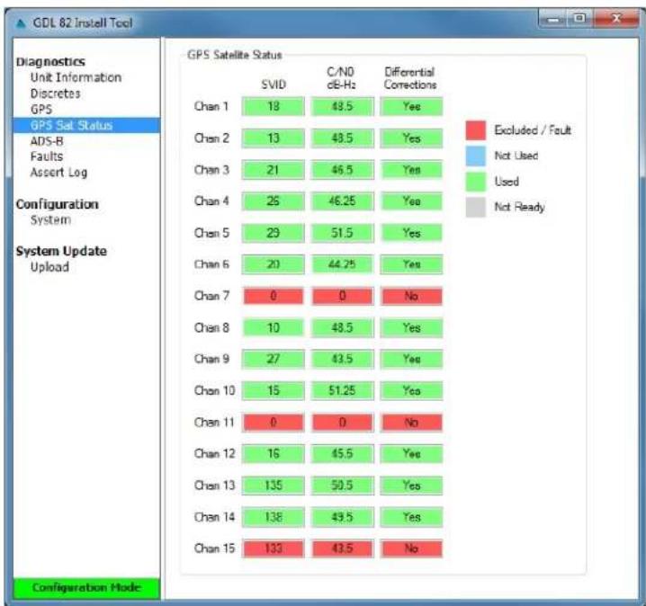
The Diagnostics / GPS Sat Status page, shown in Figure 5-3, can indicate if the GDL 82 is actively acquiring GPS satellites for the internal GPS source.
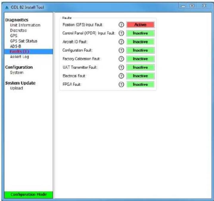
Figure 5-1: GDL 82 Install Tool, Faults Page
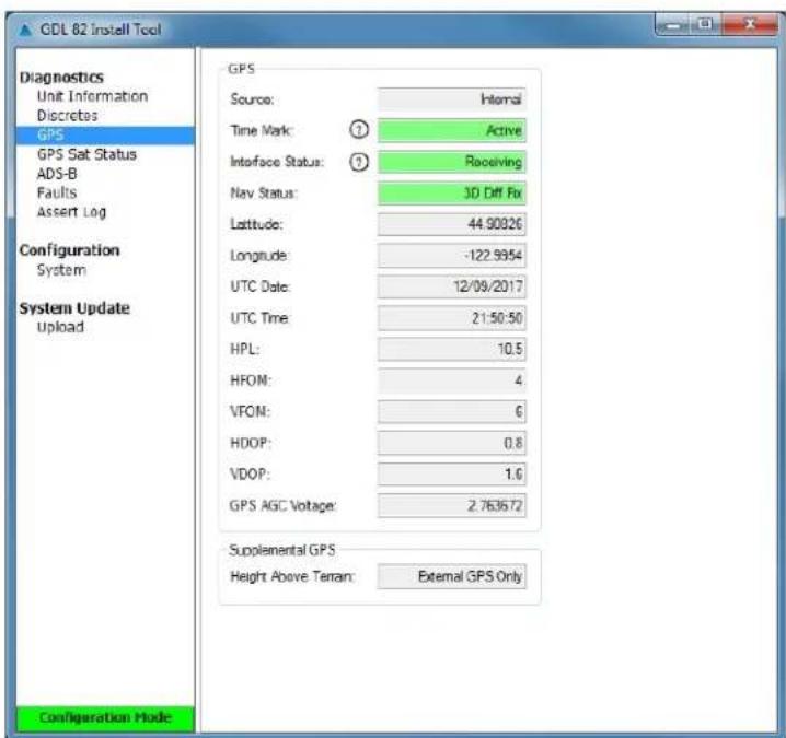
Figure 5-2: GDL 82 Install Tool, GPS Page
heatmap
GPS Satellite Status | Channel | SVID | C/N0 dB-Hz | Differential Corrections | | :--- | :--- | :--- | :--- | | Chan 1 | 18 | 43.5 | Yes | | Chan 2 | 13 | 43.5 | Yes | | Chan 3 | 21 | 46.5 | Yes | | Chan 4 | 26 | 46.25 | Yes | | Chan 5 | 29 | 51.5 | Yes | | Chan 6 | 20 | 44.25 | Yes | | Chan 7 | 0 | 0 | No | | Chan 8 | 10 | 48.5 | Yes | | Chan 9 | 27 | 43.5 | Yes | | Chan 10 | 15 | 51.25 | Yes | | Chan 11 | 0 | 0 | No | | Chan 12 | 16 | 45.5 | Yes | | Chan 13 | 135 | 50.5 | Yes | | Chan 14 | 138 | 49.5 | Yes | | Chan 15 | 133 | 43.5 | No | Configuration Mode.Figure 5-3: GDL 82 Install Tool, GPS Sat Status Page
5.4 GDL 82 Data Logging
Data logging on the GDL 82 may be used to help troubleshoot issues. Unit configuration and software data is gathered from the GDL 82 in Configuration Mode and is stored in *.csv log file. Figure 5-4 shows the Diagnostics / Assert Log page in the GDL 82 Install Tool.
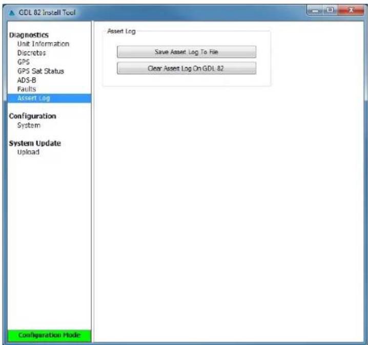
Figure 5-4: GDL 82 Install Tool, Assert Log Page
ICA/MM, GDL 82 Mooney M20() Series STC 190-01810-11
Rev. 2
5.5 GDL 82 Connector Pinout
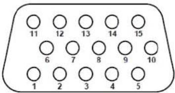
Figure 5-5: Rear View, Connector J821
Table 5-3: J821 Pinout
| Pin | GDL 82 Pin Name | I/O |
| 1 | USB D- | In/Out |
| 2 | TIME MARK A | In |
| 3 | TIME MARK B | In |
| 4 | SQUAT SWITCH* | In |
| 5 | ANONYMOUS MODE* | In |
| 6 | USB D+ | In/Out |
| 7 | GROUND | -- |
| 8 | RS-232 TX1 | Out |
| 9 | RS-232 RX1 | In |
| 10 | ADS-B OUT FAIL ANNUN | Out |
| 11 | USB V | In |
| 12 | RESERVED | -- |
| 13 | RESERVED | -- |
| 14 | GROUND | -- |
| 15 | POWER | In |
| *Active-Low:Inactive: 2 ≤ Vin ≤ 33 or Rin ≥ 130 k (Open)Active: Vin ≤ 1.0 VDC with ≥ 75 sink current, or Rin ≤ 375 (GND)Sink current is internally limited to 200 max for a grounded input. | ||
5.5.1 Discrete Inputs
The SQUAT SWITCH* input can be used to control the air/ground status of the ADS-B Out message. For Mooney aircraft an airspeed gear safe switch (if available) can be used instead of a weight on wheels or squat switch.
The ANONYMOUS MODE* can be wired into a switch to control the GDL 82 anonymity feature.
5.5.2 Discrete Output
The ADS-B OUT FAIL ANNUN output discrete can be wired to an annunciator to indicate that the ADS-B Out transmission is not operational.
6 EQUIPMENT REMOVAL & INSTALLATION

WARNING
Ensure that the aircraft power is off before removal or reinstallation of the GDL 82. Unplug any auxiliary power supply.
This section contains procedures and requirements for removal and reinstallation of equipment installed under STC SA02573SE. After removal and reinstallation, the GDL 82 Return to Service procedures must be performed in accordance with Section 8.
6.1 GDL 82 Unit
Removal
- Remove power from the GDL 82 and interfaced transponder by pulling the XPDR/UAT circuit breaker.
- Gain access to the GDL 82 unit.
- Loosen the set screw used to secure the GDL 82 15 pin D-sub to the unit, until completely disengaged.
- Disconnect the coaxial connectors from the GDL 82 unit.
- Loosen the screws securing the GDL 82 unit to the avionics shelf or mounting plate, until completely disengaged.
- Remove the GDL 82 unit.
Reinstallation
- Inspect the electrical and coaxial connectors and pins for signs of damage. Repair any damage.
- Mount the GDL 82 unit on the avionics shelf or mounting plate in accordance with the GDL 82 Mooney M20() Series STC Installation Manual, 190-01810-10.
- Reconnect the 15 pin D-sub connector, GPS, transponder and L-Band antenna coaxial connectors to the GDL 82 unit.
- Close the XPDR/UAT circuit breaker and perform the return to service procedures in accordance with Section 8.
6.2 Annunciator and Switch
Removal
- Disconnect power from the GDL 82 and interfaced transponder by pulling the XPDR/UAT circuit breaker.
- Disconnect annunciator and/or switch wiring.
- Remove annunciator and/or switch.
GARMIN
Reinstallation
- Install annunciator and/or switch in accordance with the GDL 82 Mooney M20() Series STC Installation Manual, 190-01810-10.
- Reconnect annunciator and/or switch wiring.
- Close the XPDR/UAT circuit breaker.
- Perform the return to service procedures in accordance with Section 8.
6.3 GPS Antenna
The GPS antenna is not installed by this STC. Refer to the antenna manufacturer's maintenance information for removal and reinstallation instructions.
6.4 Transponder Antenna
The transponder antenna is not installed by this STC. Refer to the antenna manufacturer's maintenance information for removal and reinstallation instructions.
GARMIN®
7 EQUIPMENT CONFIGURATION & CHECKOUT
This section contains instructions for configuration and checkout of the GDL 82 after removal and reinstallation or replacement of equipment under this STC. Steps not applicable to a particular installation may be omitted.
The person performing these procedures must be familiar with the aircraft, have a working knowledge of typical avionics systems, and has experience using the test equipment defined in this section.

NOTE
The tools called out in Section 4.2.2 are required for the checkout procedures below.
7.1 System Checkout
Original GDL 82 Reinstalled
If the original GDL 82 is reinstalled, re-configuration is not required. Continue to GDL 82 Post-Install Test (Section 7.3).
New, Repaired, or Exchanged GDL 82 Installed
If a new, repaired, or exchanged GDL 82 is installed, the applicable unit configuration from the Post Install Checkout Log in the aircraft permanent records (refer to Section 7.2) must be loaded to the unit.

NOTE
Verify the installed software version in accordance with the GDL 82 Mooney M20() Series STC Installation Manual, 190-01810-10.
7.1.1 Annunciator and Switch Check (if installed)
Operate the annunciator push-to-test button and verify the ADS-B OUT FAIL annunciator illuminates. To verify that the annunciator and/or switch is correctly interfaced to the GDL 82, reference the GDL 82 Mooney M20() Series STC Installation Manual, 190-01810-10, Section 5.3.5, for the discrete input and output checks.
7.1.2 Transponder and GPS Antenna
See antenna manufacturer's installation data for return-to-service procedures.
7.2 GDL 82 Configuration
Retrieve the Post Installation Checkout Log from the aircraft permanent records. For the maintenance activities that repaired or replaced the previous GDL 82, configure the GDL 82 as defined by the applicable data contained in the Post Installation Checkout Log. Configuration of the GDL 82 is accomplished through the GDL 8X Install Tool. Refer to the GDL 82 Mooney M20() Series STC Installation Manual, 190-01810-10, Section 5.2, for instructions on configuring the GDL 82 in accordance with this STC.

NOTE
Ensure the Post Installation Checkout Log remains with the aircraft permanent records upon completion of any maintenance activities.
GARMIN®
7.3 GDL 82 Post-Installation Test Procedures
Procedures that must be completed when the GDL 82 is removed and re-installed or replaced with a new unit are detailed in this section.
Refer to the GDL 82 Mooney M20() Series STC Installation Manual, 190-01810-10, Section 5.3, for Ground Checks using the GDL 82 Install Tool in configuration mode.
Refer to the GDL 82 Mooney M20() Series STC Installation Manual, 190-01810-10, Section 5.4, for Regulatory, ADS-B Out and EMI Checks.
If no other service is to be performed, continue to the return-to-service checks in Section 8.
8 RETURN TO SERVICE PROCEDURE
After removing and re-installing or replacing the GDL 82, perform the system configuration and checkout procedures in Section 7.
8.1 Maintenance Records
After conducting the required return-to-service procedures in accordance with this document, the aircraft may be returned to service.
Record the following information in the appropriate aircraft maintenance logs.
- Part number and serial number of any LRU which was replaced.
• Any other applicable information related to the maintenance work performed on the aircraft.
GARMIN®
APPENDIX A – INSTALLATION-SPECIFIC INFORMATION
A copy of this appendix must be used to record information for a specific installation of the GDL 82 system and maintained with the aircraft permanent records.
The GDL 82 unit specific information and configuration settings can be saved to a text file by clicking the Save Configuration To File button on the Configuration / System page in the GDL 82 Install Tool. This button will record the following data to a text file.
• Device Information: Model, Serial Number
- Software: Version, Part Number
• System Configuration:
○ Aircraft Tail Number
- ICAO Address
○ Emitter Category
○ Light Category Stall Speed
○ Squat Switch
o Transponder VFR Squawk Code
o GPS Source and Antenna Offset
○ ADS-B Anonymous Mode Switch
- 1090ES and UAT Receive Capable
ICA/MM, GDL 82 Mooney M20() Series STC 190-01810-11
Rev. 2
GARMIN
GDL 82 UNIT INFO & CONFIGURATION LOG SHEET
Date: By:
Aircraft Information
| Aircraft Make: | MOONEY |
| Aircraft Model: | |
| Aircraft Serial Number: | |
| Registration Number: |
GDL 82 Unit Information
| Unit Model: | |
| Part Number: | |
| Serial Number: | |
| Mod Level: |
Software Versions
| Software: | |
| Version: | |
| Part Number: | |
| FPGA: | |
| Version: | |
| Part Number: | |
| Internal GPS: | □ N/A |
| Version: | |
| Part Number: |
System Configuration
| Aircraft: | |
| Tail Number: | |
| ICAO Address (HEX): | |
| Emitter Category: | Light |
| Stall Speed (Kts): | |
| Squat Switch: □ Not Installed □ GND (0V) = On GND □ GND (0V) = Airborne |
Transponder:
| VFR Squawk Code: 1200 | |||
| GPS: | |||
| Source: ☐ Internal ☐ GNS Series ☐ ADS-B+ Format 2 | |||
| Lon Antenna Offset (ft): |
ADS-B:
| Anonymous Mode Switch: | Not Installed | Installed |
| 1090 ES Receive Capable: | Capable | Not Capable |
| UAT Receive Capable: | Capable | Not Capable |
ICA/MM, GDL 82 Mooney M20() Series STC 190-01810-11
Rev. 2
GARMIN®
ELECTRICAL LOAD ANALYSIS
Reference the GDL 82 Mooney M20() Series STC Installation Manual, 190-01810-10, Section 3.5, for ELA procedures.
| ITEMS ADDED TO AIRCRAFT | ELECTRICAL LOAD (A) [1] | COMMENT |
| Subtotal: |
Net Change In Bus Load:
[1] Use maximum current draw when performing this calculation.
ICA/MM, GDL 82 Mooney M20() Series STC 190-01810-11
Rev. 2
GARMIN®
EQUIPMENT INTERFACED TO GDL 82

NOTE
This information is optional and is not required to be completed or maintained with the aircraft records.
EXTERNAL GPS SOURCE
□ N/A (Internal)
□ GTN 6XX/7XX
GTN System Software:
Version: ____
Part Number: ____
□ GNS 400W/500W Series
GNS System Software:
Version:
Part Number: ____
□ GNS 480
GNS 480 System Software:
Version: ____
Part Number: ____
GPS 175/GNC 355
GPS/GNC System Software:
Version: ____
Part Number: ____
ICA/MM, GDL 82 Mooney M20() Series STC 190-01810-11
Rev. 2
GARMIN
WIRE ROUTING
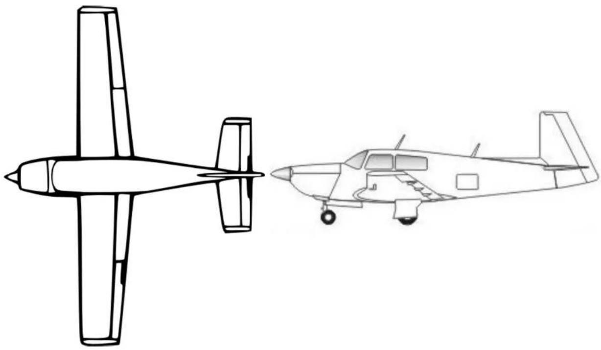
Attach aircraft wire routing diagrams showing the installed LRUs and approximate routing of the wires or a markup of the wire routing diagrams from the GDL 82 Mooney M20() Series STC Installation Manual, 190-01810-10, detailing which equipment was installed and the approximate wire routing.
natural_image
Line drawing of an airplane showing front and side views (no text or symbols)ICA/MM, GDL 82 Mooney M20() Series STC 190-01810-11
Rev. 2
GARMIN®
AIRCRAFT WIRING DIAGRAMS
Attach the aircraft wiring diagrams showing the equipment installed by this STC or a markup of the interconnect diagrams from the GDL 82 Mooney M20() Series STC Installation Manual, 190-01810-10, detailing which equipment was installed and how it was connected.
ICA/MM, GDL 82 Mooney M20() Series STC 190-01810-11
Rev. 2
GARMIN
GDL 82 Post-Installation Checkout Log
Date: By:
Ground Checks (Configuration Mode)
Software Check
☐ Software Versions verified to match the GDL 82 Mooney M20() Series STC Installation Manual (P/N 190-01810-10)
System Faults Check
Faults
Position (GPS) Input Fault: □ Inactive (green box)
Control Panel (XPDR) Input Fault: □ Inactive (green box)
Aircraft ID Fault: □ Inactive (green box)
Configuration Fault: □ Inactive (green box)
Factory Calibration Fault: □ Inactive (green box)
UAT Transmitter Fault: □ Inactive (green box)
Electrical Fault: □ Inactive (green box)
FPGA Fault: □ Inactive (green box)
GPS Source Check
GPS
Source: □ Internal □ External
Time Mark: □ Active (green box)
Interface Status: ☐ Receiving (green box)
Nav Status: □ 3D Fix or 3D Diff Fix (green box)
For Internal GPS Only □ VHF COM Interference Checked (Ref. STC IM 190-01810-10, Sec. 5.3.2)
ADS-B (Transponder) Check
Transponder
Interface Status: ☐ Receiving (green box)
Mode: □ Matches active transponder (green box)
Pressure Altitude □ Matches active altitude source
Squawk Code: □ Matches active transponder
IDENT Status: □ Matches active transponder
UAT
Address: □ Matches ICAO address of aircraft.
Flight ID: □ Matches N-number of aircraft.
Air/Ground Status: □ Indicates On Ground
Discrete Inputs and Output Check
Squat Switch: □ Discrete input checked. □ N/A
Anonymous Mode Switch: □ Switch input checked. □ N/A
Failure Annunciation: □ Discrete output checked. □ N/A
ICA/MM, GDL 82 Mooney M20() Series STC 190-01810-11
Rev. 2
GARMIN
Ground Checks (Normal Mode)
□ External Annunciator Check Performed
□ N/A
☐ Regulatory Test Performed
□ ADS-B Out Test Performed
□ EMC Check Performed
☐ Installation Specific Information (Config. Log, ELA, Wiring Diag. and Grnd Checks) Completed and Inserted in aircraft permanent records.
☐ Aircraft Weight and Balance Complete and Inserted in aircraft permanent records.
□ Complete AFMS and inserted in AFM/POH.
Notes
ICA/MM, GDL 82 Mooney M20() Series STC 190-01810-11
Rev. 2
- Instructions for Continued Airworthiness & Maintenance Manual,
- GDL 82 Mooney M20( ) Series STC
- ©2019 Garmin International or its subsidiaries All Rights Reserved
- GARMIN®
- INFORMATION SUBJECT TO EXPORT CONTROL LAWS
- DEFINITIONS OF WARNINGS, CAUTIONS, AND NOTES
- WARNING
- CAUTION
- NOTE
- TABLE OF CONTENTS
- SECTION ...... PAGE
- FIGURES
- FIGURE PAGE
- TABLES
- TABLE PAGE
- GARMIN
- INTRODUCTION
- Introduction
- Organization
- Acronyms and Abbreviations
- Publications
- Revision and Distribution
- SYSTEM DESCRIPTION
- GDL 82 Install Tool
- Device Information
- Software Loading
- Configuration
- INSTRUCTIONS FOR CONTINUED AIRWORTHINESS
- Airworthiness Limitations
- Servicing Information
- On-Condition Servicing
- Special Tools
- Maintenance Intervals
- Visual Inspection
- GDL 82 Visual Inspection
- Antenna Visual Inspection
- Post Lightning Strike Inspection
- Electrical Bonding Test
- GDL 82 Unit
- Antenna
- TROUBLESHOOTING
- General
- ADS-B OUT FAIL Annunciator
- GDL 82 Install Tool
- GDL 82 Data Logging
- GDL 82 Connector Pinout
- Discrete Inputs
- Discrete Output
- EQUIPMENT REMOVAL & INSTALLATION
- GDL 82 Unit
- Removal
- Reinstallation
- Annunciator and Switch
- GPS Antenna
- Transponder Antenna
- EQUIPMENT CONFIGURATION & CHECKOUT
- System Checkout
- Original GDL 82 Reinstalled
- New, Repaired, or Exchanged GDL 82 Installed
- Annunciator and Switch Check (if installed)
- Transponder and GPS Antenna
- GDL 82 Configuration
- GDL 82 Post-Installation Test Procedures
- RETURN TO SERVICE PROCEDURE
- Maintenance Records
- APPENDIX A – INSTALLATION-SPECIFIC INFORMATION
- GDL 82 UNIT INFO & CONFIGURATION LOG SHEET
- WIRE ROUTING
- GDL 82 Post-Installation Checkout Log
- Ground Checks (Configuration Mode)
- Ground Checks (Normal Mode)
- Notes
Brand : GARMIN
Model : GDL 82
Category : Receiver