721 - Uncategorized FLUKE - Free user manual and instructions
Find the device manual for free 721 FLUKE in PDF.


| Product Type | Pressure Calibrator |
| Brand | Fluke |
| Model | 721 |
| Pressure Range | 0 to 30 psi (2 bar) |
| Pressure Media | Non-corrosive gases |
| Accuracy | ±0.05% FS |
| Pressure Connections | 1/8 inch NPT female |
| Loop Power Supply | 24V DC, 25 mA max |
| Power Source | 4 AA alkaline batteries |
| Battery Life | Approximately 300 hours typical |
| Dimensions (H x W x D) | 200 x 100 x 60 mm |
| Weight | 1.0 kg (2.2 lb) |
| Display | Dual LCD with backlight |
| Key Functions | Pressure measurement, pressure generation, 24V loop supply, mA measurement |
| Min/Max Hold | Yes |
| Auto Shutoff | After 30 minutes idle |
| Operating Temperature | -10°C to 55°C (14°F to 131°F) |
| Storage Temperature | -20°C to 60°C (-4°F to 140°F) |
| Humidity | 0% to 90% non-condensing |
| Safety Rating | CAT II 30V |
| Overpressure Protection | Up to 45 psi |
| Cleaning | Wipe with damp cloth and mild detergent |
| Spare Parts | Battery cover, O-rings, test leads (if applicable) |
| Repairability | Field-replaceable batteries; service by qualified personnel for other repairs |
| Warranty | 1 year (standard) |
Frequently Asked Questions - 721 FLUKE
User questions about 721 FLUKE
0 question about this device. Answer the ones you know or ask your own.
Ask a new question about this device
Download the instructions for your Uncategorized in PDF format for free! Find your manual 721 - FLUKE and take your electronic device back in hand. On this page are published all the documents necessary for the use of your device. 721 by FLUKE.
USER MANUAL 721 FLUKE
Each Fluke product is warranted to be free from defects in material and workmanship under normal use and service. The warranty period is three years and begins on the date of shipment. Parts, product repairs, and services are warranted for 90 days. This warranty extends only to the original buyer or end-user customer of a Fluke authorized reseller, and does not apply to fuses, disposable batteries, or to any product which, in Fluke's opinion, has been misused, altered, neglected, contaminated, or damaged by accident or abnormal conditions of operation or handling. Fluke warrants that software will operate substantially in accordance with its functional specifications for 90 days and that it has been properly recorded on non-defective media. Fluke does not warrant that software will be error free or operate without interruption.
Fluke authorized resellers shall extend this warranty on new and unused products to end-user customers only but have no authority to extend a greater or different warranty on behalf of Fluke. Warranty support is available only if product is purchased through a Fluke authorized sales outlet or Buyer has paid the applicable international price. Fluke reserves the right to invoice Buyer for importation costs of repair/replacement parts when product purchased in one country is submitted for repair in another country.
Fluke's warranty obligation is limited, at Fluke's option, to refund of the purchase price, free of charge repair, or replacement of a defective product which is returned to a Fluke authorized service center within the warranty period.
To obtain warranty service, contact your nearest Fluke authorized service center to obtain return authorization information, then send the product to that service center, with a description of the difficulty, postage and insurance prepaid (FOB Destination). Fluke assumes no risk for damage in transit. Following warranty repair, the product will be returned to Buyer, transportation prepaid (FOB Destination). If Fluke determines that failure was caused by neglect, misuse, contamination, alteration, accident, or abnormal condition of operation or handling, including overvoltage failures caused by use outside the product's specified rating, or normal wear and tear of mechanical components, Fluke will provide an estimate of repair costs and obtain authorization before commencing the work. Following repair, the product will be returned to the Buyer transportation prepaid and the Buyer will be billed for the repair and return transportation charges (FOB Shipping Point).
THIS WARRANTY IS BUYER'S SOLE AND EXCLUSIVE REMEDY AND IS IN LIEU OF ALL OTHER WARRANTIES, EXPRESS OR IMPLIED, INCLUDING BUT NOT LIMITED TO ANY IMPLIED WARRANTY OF MERCHANTABILITY OR FITNESS FOR A PARTICULAR PURPOSE. FLUKE SHALL NOT BE LIABLE FOR ANY SPECIAL, INDIRECT, INCIDENTAL OR CONSEQUENTIAL DAMAGES OR LOSSES, INCLUDING LOSS OF DATA, ARISING FROM ANY CAUSE OR THEORY.
Since some countries or states do not allow limitation of the term of an implied warranty, or exclusion or limitation of incidental or consequential damages, the limitations and exclusions of this warranty may not apply to every buyer. If any provision of this Warranty is held invalid or unenforceable by a court or other decision-maker of competent jurisdiction, such holding will not affect the validity or enforceability of any other provision.
Fluke Corporation
P.O. Box 9090
Everett, WA 98206-9090
U.S.A.
Fluke Europe B.V.
P.O. Box 1186
5602 BD Eindhoven
The Netherlands
Table of Contents
Title
Page
Introduction....1
Contact Fluke 1
Safety Information 2
Symbols.... 3
Specifications 4
Environmental....4
Electrical and Temperature Measurement (1 year) 4
Physical 4
Required Equipment.... 6
Performance Verification Tests 6
Pressure Verification 7
DC Voltage Measure Verification 9
DC Current Measure Verification.... 10
RTD Measure Verification 10
720RTD Probe Verification.... 11
mA Loop Performance Check 11
Calibration Adjustment 12
Initiate Communication.... 12
Adjust Voltage Input 13
Adjust mA Input 13
Adjust RTD 14
Adjust Pressure 15
Maintenance.... 16
Replace the Batteries 16
Clean the Product.... 18
User-Replaceable Parts 18
Accessories 19
List of Tables
| Table | Title | Page |
| 1. | Symbols...... | 3 |
| 2. | Required Equipment for Verification and Calibration...... | 6 |
| 3. | Pressure Verification Tests...... | 7 |
| 4. | DC Voltage Measure Verification Tests...... | 9 |
| 5. | DC Current Measure Verification Tests...... | 10 |
| 6. | RTD Measure Verification Tests...... | 10 |
| 7. | 720RTD Probe Verification Tests...... | 11 |
| 8. | User-Replaceable Parts and Accessories...... | 18 |
| 9. | Accessories...... | 19 |
List of Figures
Figure
Title
- Battery Replacement 17
- User-Replaceable Parts 20
Introduction
The 721 Pressure Calibrator (the Product) is a simple to use and versatile pressure calibrator. The two internal pressure sensors are configured with different pressure measurement ranges. One range for lower pressure (P1) and one range for higher pressure (P2). The Product features inputs for mA, switch contacts, and an RTD probe. An external pressure module option gives a wider range of pressure calibration options that include absolute and differential pressure measurement.
Contact Fluke
To contact Fluke, call one of the following telephone numbers:
• Technical Support USA: 1-800-44-FLUKE (1-800-443-5853)
• Calibration/Repair USA: 1-888-99-FLUKE (1-888-993-5853)
• Canada: 1-800-36-FLUKE (1-800-363-5853)
• Europe: +31 402-675-200
• Japan: +81-3-6714-3114
• Singapore: +65-6799-5566
• Anywhere in the world: +1-425-446-5500
Or, visit Fluke's website at www.fluke.com.
To register your product, visit http://register.fluke.com.
To download manuals, or to view, print, or download the latest manual supplement, visit http://us.fluke.com/usen/support/manuals.
Safety Information
A Warning identifies conditions and procedures that are dangerous to the user.
A Caution identifies conditions and procedures that can cause damage to the
Product or the equipment under test.
Warning
To prevent possible electrical shock, fire, or personal injury:
- Only assemble and operate high-pressure systems if you know the correct safety procedures. High-pressure liquids and gases are hazardous and the energy from them can be released without warning.
- Read all safety information before you use the Product.
- Carefully read all instructions.
- Do not use the Product around explosive gas or vapor.
- Use the correct terminals, function, and range for measurements.
- Do not apply more than the rated voltage, between the terminals or between each terminal and earth ground.
- Do not touch voltages >30 V ac rms, 42 V ac peak, or 60 V dc.
- Remove all probes, test leads, and accessories before the battery door is opened.
- Do not exceed the Measurement Category (CAT) rating of the lowest rated individual component of a Product, probe, or accessory.
- Disable the Product if it is damaged.
- Do not use the Product if it is damaged.
- Remove the input signals before you clean the Product.
- Use only specified replacement parts.
- Have an approved technician repair the Product.
- Use the Product only as specified, or the protection supplied by the Product can be compromised.
-
Pressure sensors can be damaged and/or personnel injury can occur due to improper application of pressure. Vacuum should not be applied to any gauge pressure sensor. The Product display shows “OL” when an inappropriate pressure is applied. If “OL” is shown on any pressure display, the pressure should be reduced or vented immediately to prevent Product damage or possible personnel injury. “OL” is shown when the pressure exceeds 110 % of the nominal range of the sensor or when a vacuum in excess of 2 PSI is applied on gauge range sensors.
-
Push the ZERO button to zero the pressure sensor when vented to atmospheric pressure.
- Remove the batteries if the Product is not used for an extended period of time, or if stored in temperatures that exceed the battery manufacturer's specifications. If the batteries are not removed, battery leakage can damage the Product.
- Replace the batteries when the low battery indicator shows to prevent incorrect measurements.
- Be sure that the battery polarity is correct to prevent battery leakage.
- Repair the Product before use if the battery leaks.
- The battery door must be closed and locked before you operate the Product.
- Use only specified replacement parts.
Symbols
Symbols used on the Product or in this manual are shown in Table 1.
Table 1. Symbols
| Symbol | Description | Symbol | Description |
 | Risk of Danger. Important information. See Manual. |  | Conforms to relevant North American Safety Standards. |
| [OWHS] | Hazardous voltage. Risk of electric shock. | [W287] | Double Insulated |
| [S42Y] | Conforms to European Union directives. |  | Conforms to relevant Australian EMC standards. |
 | Inspected and licensed by TÜV Product Services. | [35X6] | Battery |
 | This product complies with the WEEE Directive (2002/96/EC) marking requirements. The affixed label indicates that you must not discard this electrical/electronic product in domestic household waste.Product Category: With reference to the equipment types in the WEEE Directive Annex I, this product is classed as category 9 "Monitoring and Control Instrumentation" product. Do not dispose of this product as unsorted municipal waste. Go to Fluke's website for recycling information. |  | Conforms to relevant South Korean EMC Standards. |
Specifications
Conditions for specifications are 15^ C to 35^ C unless otherwise noted.
Environmental
Operating Temperature ....-10 °C to +50 °C (14 °F to +122 °F)
Storage
With Batteries .... Per battery manufacturer's specification, not to exceed storage specification without batteries.
Without Batteries ....-20 °C to +60 °C (-4 °F to +140 °F)
Altitude....2000 m
Power Requirements 6 V dc
Batteries 4 AA batteries (alkaline)
Battery Life ....>35 hours, typical usage
Electrical and Temperature Measurement (1 year)
| Function | Range | Resolution | Accuracy |
| mA Measure 0 to 24 mA 0.001 mA | ±0.015 % of rdg ±0.002 mA | ||
| V dc Measure 0 to 30 V dc 0.001 V | ±0.015 % of rdg ±0.002 V | ||
| *Temperature measure (RTD/Ohms) | -40 °C to 150 °C (-40 °F to 302 °F) | 0.01 °C, 0.01 °F | ±0.015 % of rdg ±0.02 Ω; ±0.1 °C (±0.2 °F) ±0.25 °C (±0.45 °F) combined uncertainty when using 720 RTD probe accessory |
| Loop Power Supply 24 V N/A 24 mA @ 24 V | |||
| *Temperature measurement requires optional 720RTD Pt-100 RTD probe available as an accessory. | |||
Physical
Dimensions (with holster) ....(H x W x D) (20 x 11 x 5.8) cm, (7.9 x 4.3 x 2.3) in
Weight (with holster) 0.539 kg (1 lb 3 oz)
EMI/RFI Conformance ...... EN50082-1 and EN55022: Class B
Ingress Protection IP40
Connectors/Ports
Pressure ...... Two, 1/8 in NPT, 700P Series Pressure Module
RTD.... RTD probe
Temperature Effect (all functions)....No effect on accuracy on all functions from 15 °C to 35 °C
Add ±0.002 % F.S./°C for temperatures outside of 15 °C to 35 °C
| 1-year Specifications Low | Pressure Sensor High Pressure Sensor | ||||||
| Model | Calibrator Description | Range Sensor 1 | Resolution Sensor 1 | Accuracy Sensor 1 | Range Sensor 2 | Resolution Sensor 2 | Accuracy Sensor 2 |
| 721-1601 | 16 PSIG, 100 PSIG | -14 psi + 16 psi -0.97 bar to 1.1 bar | 0.001 psi, 0.0001 bar | 0.025 % of full scale | -12 psi to +100 psi -0.83 bar to 6.9 bar | 0.001 psi 0.0001 bar | 0.025 % of full scale |
| 721-1603 | 16 PSIG, 300 PSIG | -12 psi to +300 psi -0.83 bar to 20 bar | 0.01 psi 0.001 bar | ||||
| 721-1605 | 16 PSIG, 500 PSIG | -12 psi to +500 psi -0.83 bar to 34.5 bar | 0.01 psi 0.001 bar | ||||
| 721-1610 | 16 PSIG, 1000 PSIG | 0 psi to +1000 psi 0.00 bar to 69 bar | 0.01 psi 0.001 bar | ||||
| 721-1615 | 16 PSIG, 1500 PSIG | 0 psi to +1500 psi 0.00 bar to 103.4 bar | 0.1 psi 0.01 bar | ||||
| 721-1630 | 16 PSIG, 3000 PSIG | 0 psi to +3000 psi 0.00 bar to 200 bar | 0.1 psi 0.01 bar | ||||
| 721-1650 | 16 PSIG, 5000 PSIG | 0 psi to +5000 psi 0.00 bar to 345 bar | 0.1 psi 0.01 bar | 0.035 % of full scale | |||
| 721-3601 | 36 PSIG, 100 PSIG | -14 psi + 36 psi -0.97 bar to 2.48 bar | -12 psi to +100 psi -0.83 bar to 6.9 bar | 0.001 psi 0.0001 bar | 0.025 % of full scale | ||
| 721-3603 | 36 PSIG, 300 PSIG | -12 psi to +300 psi -0.83 bar to 20 bar | 0.01 psi 0.001 bar | ||||
| 721-3605 | 36 PSIG, 500 PSIG | -12 psi to +500 psi -0.83 bar to 34.5 bar | 0.01 psi 0.001 bar | ||||
| 721-3610 | 36 PSIG, 1000 PSIG | 0 psi to +1000 psi 0.00 bar to 69 bar | 0.01 psi 0.001 bar | ||||
| 721-3615 | 36 PSIG, 1500 PSIG | 0 psi to +1500 psi 0.00 bar to 103.4 bar | 0.1 psi 0.01 bar | ||||
| 721-3630 | 36 PSIG, 3000 PSIG | 0 psi to +3000 psi 0.00 bar to 200 bar | 0.1 psi 0.01 bar | ||||
| 721-3650 | 36 PSIG, 5000 PSIG | 0 psi to +5000 psi 0.00 bar to 345 bar | 0.1 psi 0.01 bar | 0.035 % of full scale | |||
Electromagnetic Environment ...... IEC 61326-1: Portable
Electromagnetic Compatibility....Applies to use in Korea only. Class A Equipment (Industrial Broadcasting & Communication Equipment) [1]
[1] This product meets requirements for industrial (Class A) electromagnetic wave equipment and the seller or user should take notice of it. This equipment is intended for use in business environments and is not to be used in homes.
Required Equipment
The equipment listed in Table 2 is necessary to do the performance verification tests and calibration adjustment.
Table 2. Required Equipment for Verification and Calibration
| Equipment Minimum Specifications Recommended Model | ||
| Low-thermal EMF banana to banana leads | - | Pomona 2948-36-2 (red) and 2948-36-0 (black) |
| RTD adapter - Fluke 720URTDA | ||
| Calibrator/Resistance Standard | 0 V to 30 VAccuracy: 0.006 % rdg ±0.5 mV0 mA to 24 mAAccuracy: 0.006 % rdg ±0.25 μA-40 °C to 150 °C RTD0.033 °C | Fluke Calibration 7526A |
| Pressure Controller/Calibrator | -14 PSI to 1000 PSI0.005 % | Ruska 7250xi |
| Piston Gauge | 3000 PSI to 5000 PSI0.005 % | Fluke Calibration PG7302 or PG7202 |
| Metrology Well | -30 °C to 140 °C0.06 °C | Fluke Calibration 9170 |
Performance Verification Tests
Warning
To prevent possible electrical shock, fire, or personal injury, do not perform the performance test or verification test procedures unless the Product is fully assembled.
The performance tests verify the complete operation of the Product and measure the accuracy of each function against Product specifications. If the Product fails a part of the test, calibration adjustment or repair is necessary. See “Calibration Adjustment Procedure”.
The performance verification tests check the accuracy of each Product function against its specifications. If the Product fails any of these tests, calibration adjustment or repair is necessary.
Pressure Verification
To do the pressure verification test:
- Carefully attach the pressure fitting of the Pressure Controller/Calibrator or Piston Gauge (called pressure source for the remainder of this procedure) to the first pressure port of the Product.
Note
Use plenty of TEFLON tape when attaching pressure fitting.
The display should read 0.00 PSI with the deadweight tester opened up to ambient air. If not, push ZERO until both displays read 0.00 PSI.
- Set up the deadweight tester for the sequence of PSI inputs from Table 3 to be injected into the pressure port of the Product.
- Ensure the pressure has stabilized at each input before you verify the display reading.
- Carefully vent all pressure and disconnect the first pressure port.
- Connect and test the second pressure port.
- Set up the deadweight tester for the sequence of PSI inputs from Table 3 to be injected into the pressure port of the Product.
- Ensure the pressure has stabilized at each input before you verify the display reading.
- Set up the deadweight tester for the sequence of PSI inputs from Table 3 to be injected into the pressure port of the Product.
- Ensure the pressure has stabilized at each input before you verify the display reading.
Table 3. Pressure Verification Tests
| 16 PSI 36 PSI | ||
| Input Pressure | Lower Limit | Upper Limit |
| 16.000 | 15.996 | 16.004 |
| 13.000 | 12.996 | 13.004 |
| 10.000 | 9.996 | 10.004 |
| 6.000 | 5.996 | 6.004 |
| 3.000 | 2.996 | 3.004 |
| 0.000 | -0.004 | 0.004 |
| -5.000 | -5.004 | -4.996 |
| -10.000 | -10.004 | -9.996 |
| -13.750 | -13.754 | -13.746 |
| Input Pressure | Lower Limit | Upper Limit |
| 36.000 | 35.991 | |
| 29.000 | 28.991 | |
| 22.000 | 21.991 | |
| 14.000 | 13.991 | |
| 7.000 | 6.991 | |
| 0.000 | -0.009 | 0.009 |
| -5.000 | -5.009 | |
| -10.000 | -10.009 | -9.991 |
| -13.750 | -13.759 | -13.741 |
Table 3. Pressure Verification Tests (cont.)
| 100 PSI 300 PSI | ||
| Input Pressure | Lower Limit | Upper Limit |
| 100.00 | 99.975 | 100.025 |
| 80.00 | 79.975 | 80.025 |
| 60.00 | 59.975 | 60.025 |
| 40.00 | 39.975 | 40.025 |
| 20.00 | 19.975 | 20.025 |
| 0.00 | -0.025 | 0.025 |
| -6.00 | -6.025 | -5.975 |
| -12.00 | -12.025 | -11.975 |
| Input Pressure | Lower Limit | Upper Limit |
| 300.00 | 299.92 | 300.08 |
| 240.00 | 239.92 | 240.08 |
| 180.00 | 179.92 | 180.08 |
| 120.00 | 119.92 | 120.08 |
| 60.00 | 59.92 | 60.08 |
| 0.00 | -0.08 | |
| -6.00 | -6.08 | -5.92 |
| -12.00 | -12.08 | -11.92 |
| 500 PSI 1000 PSI | ||
| Input Pressure | Lower Limit | Upper Limit |
| 500.00 | 499.87 | 500.13 |
| 400.00 | 399.87 | 400.13 |
| 300.00 | 299.87 | 300.13 |
| 200.00 | 199.87 | 200.13 |
| 100.00 | 99.87 | 100.13 |
| 0.00 | -0.13 | 0.13 |
| -6.00 | -6.13 | -5.87 |
| -12.00 | -12.13 | -11.87 |
| Input Pressure | Lower Limit | Upper Limit |
| 1000.0 | 999.75 | 1000.25 |
| 800.0 | 799.75 | 800.25 |
| 600.0 | 599.75 | 600.25 |
| 400.0 | 399.75 | 400.25 |
| 200.0 | 199.75 | 200.25 |
| 0.0 | -0.25 | 0.25 |
| 1500 PSI | ||
| Input Pressure | Lower Limit | Upper Limit |
| 1500.0 | 1499.6 | 1500.4 |
| 1200.0 | 1199.6 | 1200.4 |
| 900.0 | 899.6 | 900.4 |
| 600.0 | 599.6 | 600.4 |
| 300.0 | 299.6 | 300.4 |
| 0.0 | -0.4 | 0.4 |
| 3000 PSI | ||
| Input Pressure | Lower Limit | Upper Limit |
| 3000.0 | 2999.2 | 3000.8 |
| 2400.0 | 2399.2 | 2400.8 |
| 1800.0 | 1799.2 | 1800.8 |
| 1200.0 | 1199.2 | 1200.8 |
| 600.0 | 599.2 | 600.8 |
| 0.0 | -0.8 | 0.8 |
Table 3. Pressure Verification Tests (cont.)
| 5000 PSI | ||
| Input Pressure | Lower Limit Upper Limit | |
| 5000.0 | 4998.2 | 5001.8 |
| 4000.0 | 3998.2 | 4001.8 |
| 3000.0 | 2998.2 | 3001.8 |
| 2000.0 | 1998.2 | 2001.8 |
| 1000.0 | 998.2 | 1001.8 |
| 0.0 | -1.8 | 1.8 |
- Carefully vent all pressure and disconnect the second pressure port.
DC Voltage Measure Verification
To do the dc voltage measure verification test:
- Push F2 repeatedly until VOLTS is shown on the third row of the Product display.
- Connect the Product red banana jack (V mA) to the Calibrator HI VOLTS output.
- Connect the Product black banana jack (COM) to the Calibrator LO VOLTS output.
- Set the Calibrator for the voltage setting in Table 4, and verify the display reading on the Product.
Table 4. DC Voltage Measure Verification Tests
| Applied Voltage from 7526A Lower limit Upper Limit | |
| 0.000 V -0.002 V 0.002 V | |
| 15.000 V 14.996 V 15.004 V | |
| 30.000 V 29.994 V 30.007 V |
- Set the Calibrator to Standby.
DC Current Measure Verification
To do the dc current measure verification test:
- Push F2 repeatedly until mA is shown in the third row of the Product display.
- Connect the Product red banana jack (V mA) to the Calibrator HI mA output.
- Connect the Product black banana jack (COM) to the Calibrator LO mA output.
- Set the Calibrator for the current setting in Table 5, and verify the display reading on the Product.
Table 5. DC Current Measure Verification Tests
| Applied Current from the Calibrator | Lower limit Upper Limit |
| 4.000 mA 3.997 mA 4.003 mA | |
| 12.000 mA 11.996 mA 12.004 mA | |
| 24.000 mA 23.994 mA 24.006 mA |
- Set the Calibrator to Standby.
RTD Measure Verification
- Push F2 repeatedly until RTD is shown in the third row of the Product display.
- Connect the RTD Adapter to the Product.
- Connect the RTD Adapter Current HI to the Calibrator HI RTD output.
- Connect the RTD Adapter Sense HI to the Calibrator HI RTD output.
- Connect the RTD Adapter Current LO to the Calibrator LO RTD output.
- Connect the RTD Adapter Sense LO to the Calibrator LO RTD output.
- Set the Calibrator to the 400 Ω range, output the resistance setting in Table 6, and verify that the display reading on the Product is within the limits.
- Set Calibrator to standby.
Table 6. RTD Measure Verification Tests
| Applied Current from the Calibrator | Lower limit Upper Limit | |
| 84.270 Ω | -40.10 °C | -39.90 °C |
| 100.000 Ω | -0.10 °C | 0.10 °C |
| 157.325 Ω | 149.90 °C | 150.10 °C |
720RTD Probe Verification
This is an optional test for a Product that is paired with a 720RTD. To do this test:
- Push F2 repeatedly until RTD is shown in the third row of the Product display.
- Plug the 720RTD probe into the Product.
- Insert the probe into the Metrology Well.
- Set the Metrology Well to the temperatures in Table 7, after the Well stabilizes, verify that the display readings are within tolerance.
Table 7. 720RTD Probe Verification Tests
| Applied Temperature Lower Limit Upper Limit | ||
| -30.00 °C | -30.25 °C | -29.75 °C |
| 0.00 °C | -0.25 °C | 0.25 °C |
| 70.00 °C | 69.75 °C | 70.25 °C |
| 130.00 °C | 129.75 °C | 130.25 °C |
- Set the Metrology Well to Standby.
mA Loop Performance Check
The Loop Voltage function does not have traceable specifications, this is a functional check.
- Push F2 repeatedly until mA Loop is shown in the third row of the Product display.
- Connect the Product red banana jack (V mA) the Calibrator HI input.
- Connect the Product black banana jack (COM) to the Calibrator LO input
- Set the Calibrator to the 100 V range, the voltage measured should be between 22 V and 30 V.
Calibration Adjustment
The Product has an electronic calibration process. There are no mechanical adjustments and the calibration is done with the case closed. A serial communications port is used for the calibration process to send commands and receive readings. The normal RS232 interface is used. Calibration can be done with a terminal program or an automated-calibration program can be written with programs like MetCal. In this manual, only the serial terminal mode is described.
Table 2 lists the required equipment.
Initiate Communication
Terminal communications can be set up with terminal communication software on a PC such as Hyperterminal or Ucon. Connect the RS232 cable to the 5-pin Lemo on the side of the Product. Connect the other end of the cable to the terminal/PC serial port.
The terminal settings need to be set as follows:
- Bits per second: 9600
- Data bits: 8
- Parity: None
- Stop bits: 1
- Flow control: none
- Local echo: on
First, enable the full-command set by sending HC_GASUI_OFF. Check that it turned off by sending HC_GASUI?, The Product should reply OFF. All calibration commands are done on the functions selected on the lower display. Use the following command sequence to turn off all but the lower display:
DISPLAY UPPER, OFF DISPLAY MIDDLE, OFF DISPLAY LOWER, ON
As long as the Product has been at a stable temperature, within the range of 20 °C to 26 °C for an hour or longer, the Product only needs 5 minutes to warm up. If temperature conditions were previously below 10 °C or higher than 40 °C , then the unit must be allowed to stabilize for a minimum of 3 hours prior to calibration.
Adjust Voltage Input
To adjust the voltage input:
- Use the test lead set to attach the voltage output of the Calibrator to the input of the Product.
- Send this command to put the Product into Voltage mode: FUNC LOWER, DCV
- Use the Calibrator to input 0 V.
- When the reading is stable, send this command: CAL_POINT[0] [0]
- Use the Calibrator to input 30 V.
- When the reading is stable, send this command: CAL_POINT[0][1]
- The voltage range is now calibrated.
Adjust mA Input
To adjust the mA input:
- Use the test lead set to attach the voltage output of the Calibrator to the input of the Product.
- Send this command to put the Product in Current mode: FUNC LOWER, DCI
- Use the Calibrator to input 0 mA.
- When the reading is stable, send this command: CAL_POINT[0][0]
- Use the Calibrator to input 24 mA.
- When the reading is stable, send this command: CAL_POINT[0][1]
- The voltage range is now calibrated. Use the Calibrator to verify calibration.
Adjust RTD
Before the adjustment, make these connections:
- Plug the RTD Adapter into the Product.
- Connect the high side of the current output (ohms measure) jacks of the RTD Adapter to the high side of the current input of the Resistance Standard.
- Connect the low side of the current output (ohms measure) of the RTD Adapter to the low side of the current input of the Resistance Standard.
- Connect the high side of the sense jacks of the RTD Adapter to the high side of the sense output of the Resistance Standard.
- Connect the low side of the sense jacks of the RTD Adapter sense input to the low side of the sense output of the Resistance Standard.
To make the adjustment:
- After you have made your connections, send this command to put the unit in RTD mode: FUNC LOWER,RTD
- Use the Resistance Standard to input 90 Ω.
- When the reading is stable send this command: CAL_POINT[0][0]
- Use the Resistance Standard to input 140 Ω.
- When the reading is stable, send this command: CAL_POINT[0][1]
- The RTD range is now calibrated. Use the Resistance Standard to verify calibration.
Adjust Pressure
The Product uses a 1/8 inch NPT female connection in the pressure input port. Various adapters may be necessary to connect to the pressure standard. Always make sure the hose, tubing, fittings, etc., have a rated working pressure at or above the pressure of the Product. It is important that there are no leaks. Use Teflon tape where appropriate.
To adjust the pressure:
- Send this command to put the Product into pressure mode:
FUNC LOWER, {port} where port is either P1 or P2. - Send the OFFSET_ADJ? command.
- Note the value returned.
- Use the Pressure Standard to input a value equal or close to the noted value.
- When the pressure is stable, send the OFFSET_ADJ n command where n is the entered pressure.
- Send the GAIN_ADJ? command.
- Note the value returned.
- Use the Pressure Standard to input a value equal or close to the noted value.
- When the pressure is stable, send the command GAIN_ADJ n where n is the applied pressure.
The pressure is now adjusted. Restore normal operation by turning the other displays back on. Send DISPLAY UPPER, ON then DISPLAY MIDDLE, ON. Check the unit display. There should be three bars across the display, the upper three show reading, the bottom showing the F key functions. Then, send HC_GASUI_ON. Verify that it is on by sending HC_GASUI?. The unit should reply ON.
Maintenance
Replace the Batteries
If the batteries discharge too far, the Product automatically shuts down to prevent battery leakage.
Note
Use only AA size alkaline batteries.
Warning
To prevent possible electrical shock, fire, or personal injury:
- Remove the batteries if the Product is not used for an extended period of time, or if stored in temperatures above 50 °C. If the batteries are not removed, battery leakage can damage the Product.
- Replace the batteries when the low battery indicator shows to prevent incorrect measurements.
- Be sure that the battery polarity is correct to prevent battery leakage.
- Repair the Product before use if the battery leaks.
- The battery door must be closed and locked before you operate the Product.
To change the batteries, see Figure 1:
- Turn off the Product.
- Turn the Product so that the display is down.
- With a flat-head screwdriver, remove the battery door screw.
- Replace the four AA batteries with new batteries. Make sure that the polarity on the batteries is correct.
- Replace the battery door.
- Tighten the battery door screw.
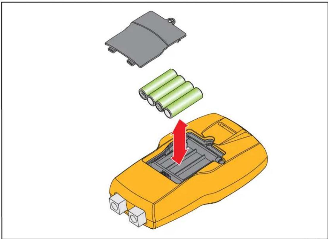
natural_image
Illustration of a yellow battery pack with three batteries and one battery, showing internal structure and battery stack (no text or symbols)Figure 1. Battery Replacement
hmq061.eps
Clean the Product
Caution
To avoid damaging the plastic lens and case, do not use solvents or abrasive cleansers.
Clean the Product with a soft cloth dampened with water or water and mild soap.
User-Replaceable Parts
⚠ Warning
To prevent possible electrical shock, fire, or personal injury, use only specified replacement parts.
User-replaceable parts are listed in Table 8 and shown in Figure 2. For more information about these items, contact a Fluke representative. See the “Contact Fluke” section of this manual.
Table 8. User-Replaceable Parts and Accessories
| Item Number | Description | Qty | Part Number |
| 1 | Case Top Assembly For 721 | 1 | 4409796 |
| 2 | Fluke-721 Lens, 721 | 1 | 4364743 |
| 3 | Screw, 5-20k.312, Ph, Threaded | 4 | 494641 |
| 4 | Fluke-7xx, Display Module | 1 | 4404450 |
| 5 | Fluke-721 Keypad | 1 | 4364568 |
| 6 | Conn, Panel Mount, Circ, | 1 | 942714 |
| 7 Insulator, Input Receptacle, Red 1 664257 | |||
| 8 Insulator, Input Receptacle, Black 1 664265 | |||
| 9 | Battery, AA, Alkaline | 4 | 376756 |
| 10 | Fluke-721 Beltline Gasket, Black | 1 | 4364546 |
| 11 | Case Bottom Assembly For 721 | 1 | 4409801 |
| 12 | Fluke-721-2003,Holster, Yellow | 1 | 43 |
| 13 | Fluke-721 Battery Door, Gray 8 | 1 | 4364522 |
| 14 Screw, 4x5/16, Pan Head 5 642931 | |||
| 15 | Fluke-721 Foot, Black | 2 | 4364579 |
| Not Shown | Decal, Manifold Range,100 Psi, | 1 | 4110705 |
| Not Shown | Decal, Manifold Range,300 Psi | 1 | 4110710 |
| Not Shown | Decal, Manifold Range,500 Psi | 1 | 4110722 |
| Not Shown | Decal, Manifold Range,1000 Psi | 1 | 4110731 |
| Not Shown | Decal, Manifold Range,3000 Psi | 1 | 4110746 |
4364505
Table 9. User-Replaceable Parts and Accessories (cont.)
| Item Number | Description | Qty | Number |
| Not Shown | Decal, Manifold Range,5000 Psi | 1 | 4110754 |
| Not Shown | Decal, Manifold Range 16psi 1.1bar | 1 | 4374274 |
| Not Shown | Decal, Manifold Range 36psi 2.5bar | 1 | 4374288 |
| Not Shown | Decal, Manifold Range 1500psi 100bar | 1 | 4374301 |
| Not Shown | Fluke-721,Decal, Rear, Serial Number Plate | 1 | 4364755 |
| Not Shown | Tie, Cable, 4" | 1 | 172080 |
| See www.fluke.com for more information about the test leads and alligator clips available for your region. | |||
Part
Accessories
Table 9 is a list of available accessories for the Product.
Table 10. Accessories
| Part Number | Description |
| 4382695 | Fluke-720URTDA,Universal RTD Adapter, For 719Pro And 721 |
| 4380630 721 | Carrying Case |
| See www.fluke.com for more information about the test leads and alligator clips available for your region. | |
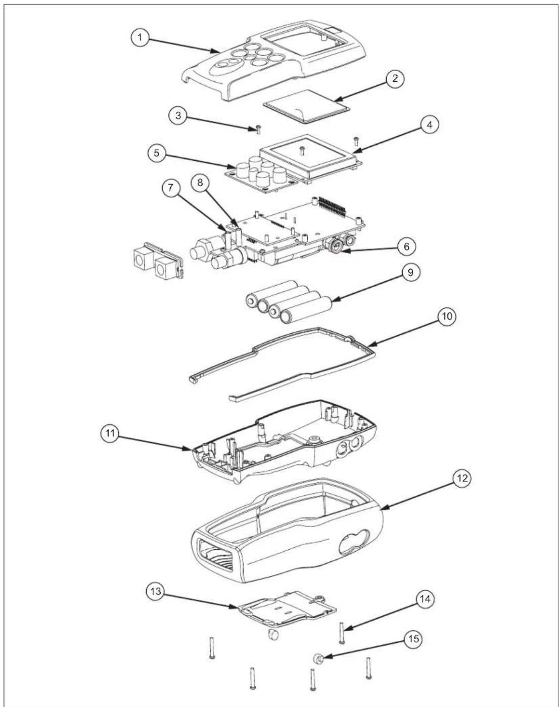
Figure 2. User-Replaceable Parts
hmq101.eps
- Table of Contents
- Title
- Page
- List of Tables
- List of Figures
- Figure
- Introduction
- Contact Fluke
- Safety Information
- Warning
- Symbols
- Specifications
- Environmental
- Physical
- Required Equipment
- Performance Verification Tests
- Pressure Verification
- Note
- DC Voltage Measure Verification
- DC Current Measure Verification
- RTD Measure Verification
- 720RTD Probe Verification
- mA Loop Performance Check
- Calibration Adjustment
- Initiate Communication
- Adjust Voltage Input
- Adjust mA Input
- Adjust RTD
- Adjust Pressure
- Maintenance
- Replace the Batteries
- Clean the Product
- Caution
- User-Replaceable Parts
- ⚠ Warning
- Accessories
Brand : FLUKE
Model : 721
Category : Uncategorized