
6 (2015) - Car MG - Free user manual and instructions
Find the device manual for free 6 (2015) MG in PDF.


| Product Type | Passenger Car |
| Brand | MG |
| Model | 6 (2015) |
| Overall Length | 4657 mm |
| Overall Width | 1827 mm |
| Overall Height (unladen) | 1467 mm |
| Wheelbase | 2705 mm |
| Fuel Tank Capacity | 62 L |
| Luggage Capacity | 429 L |
| Engine Type | D1.9 Turbo Diesel |
| Engine Capacity | 1.850 L |
| Maximum Power | 110 kW @ 4000 rpm |
| Maximum Torque | 350 Nm @ 1800-2600 rpm |
| Transmission | 6-Speed Manual |
| Kerb Weight (Diesel) | 1521-1539 kg |
| Gross Vehicle Weight | 2140 kg |
| Towing Capacity (braked) | 1600 kg |
| Wheel Size | 7J × 16 |
| Tyre Size | 205/60R16 |
| Tyre Pressure (cold) | 2.2 bar (32 psi) front and rear |
| Fuel Type | Diesel (EN590) |
| Engine Oil Capacity | 5.0 L (C3 5W-30) |
| Coolant Capacity | 7.7 L (OAT glycol) |
| Safety Systems | ABS, EBD, SRS airbags, TPMS, Cruise Control, Stability Control |
| Service Interval | 15,000 miles / 24,000 km or 12 months |
Frequently Asked Questions - 6 (2015) MG
User questions about 6 (2015) MG
0 question about this device. Answer the ones you know or ask your own.
Ask a new question about this device
Download the instructions for your Car in PDF format for free! Find your manual 6 (2015) - MG and take your electronic device back in hand. On this page are published all the documents necessary for the use of your device. 6 (2015) by MG.
USER MANUAL 6 (2015) MG
VehicldentificationInformation....3
Vehicle identification....3
VehicldentificationLabel....4
I InstrumentsandControls....5
Instruments and Controls Overview....6
InstrumenPack....8
EngineCoolant Temperature Gauge....8
Tachometer....9
Speedometer....9
FueGauge....9
MessageCentre....10
Temperature and Clock....10
GearPositionDisplay/GearChangeReminder....10
CONTENTS
Odometer....10
VehicleInformationDisplay....I
Warning lights and indicators....26
LightingSwitch....34
MasteLightingSwitch....34
InstrumenDimmerControl....35
ManualAdjustmentHeadlightLevelling * 35
DynamicHeadlampLevelling 36
CorneringLamps * 36
Fog lights....37
DirectionIndicator/MainBeamLever....38
Hazard Warning lights....39
WipersandWashers....40
FrontWindscreenWiperControls....40
Programmed WasWipe....41
HeadlampWashers * 42
RainSensor * 42
SteeringColumn....43
SteeringColumnAdjustment....43
CONTENTS
Horn....44
Mirrors....45
ExteriorMirrors....45
InteriorRear-viewMirror....47
VanityMirror....48
Windows....49
PowerOperatedWindowSwitch....49
WindowOperation....49
InteriorLight....51
FronCourtesy and Map Reading lights....51
RealCourtesyLight....52
PowerSocket....53
FronPoweSocket....53
AccessoryPowerSocket 53
StorageEquipment....55
Ashtray....55
Glovebox....55
CubbyBox....56
CONTENTS
CupHolder....57
Front Cup Holder....57
Real Cup Holder....57
2AiConditioning....59
Ventilation....60
Vents....61
ElectronicAirConditioningControls * 63
ConsolePanel....63
AirConditioningDisplay....64
AiDistribution....64
Blower....65
HeatedReaScreen....65
A/Button....65
AiRecirculation....66
Defrost/Demist....66
AutomaticAirConditioningControls * 67
ConsolePanel....67
AutomaticAirConditioningDisplay....68
CONTENTS
AUTOControl....68
ManuaControl....69
Blower....70
DuaZone Temperature Control....70
MONOControl....70
HeatedReaScreen....71
A/Button....71
OFF....71
AiRecirculation....72
Defrost/Demist....72
Heated From Seats....73
3AudioSystem....75
AudioSystem * 76
AudioSystemControlPanel....77
ControButtons....78
BasicOperation....78
RadioOperation....80
CDUSBAUXPlayer....82
Antenna....84
CONTENTS
4SeatsandRestraints....85
Seats......86
CorrectSeatingPosition....86
HeadRestraints....87
ManualFrontSeat * 88
PowerFrontSeat * 89
Heating From Seat....89
FoldingheReaSeats....90
SeaBelts....92
SafetyInformation....92
FasteninghBelt....93
Releasing the Belt 94
UpperAnchorageHeightAdjustment....94
CheckingSeaBelts....94
Replacing Sea Belts....95
SeatBeltPre-tensioners 95
AirbagSupplementaryRestraintSystem....96
Airbags....96
ChildRestraints....103
CONTENTS
Child Restraint Instructions....103
5StartingandDriving......III
Handsets....112
Introduction......112
HandseBatteryRemovingandRefitting....113
EmergencyKey....115
Child-ProofLocks....116
AlarmSystem....117
Starting and Driving....122
Dockingstation....122
StartingheEngine....123
Driving....124
Stopping Engine....124
EconomicalandEnvironmentalDriving....126
Running-in....126
CONTENTS
Environment Protection....126
Drivingstyle....126
How to save fuel and extend the life of the vehicle....127 Maintenance....129
DieseParticulateFilter....I 30
Fuel....130
Starting....130
Driving....131
FueSystem....132
FueRequirements....132
FueFiller....132
FueFilling....133
Inertiswitch....134
6-SpeedManual Transmission....136
BrakeSystem....137
FooBrake....137
Anti-locIBrakéSystem(ABS)....139
ElectricParIBrake(EPB)....141
StabilityControlSystemandT ractionControlSystem....144
CONTENTS
StabilityControlSystem(SCS)....144
TractionControlSystem(TCS)....144
SwitchingOrandOff....145
SCS/TCS Warning light....145
T yrePressureMonitoringSystem(TPMS)....146
CruiseControl * 148
IntelligenStop/StarSystem....150
ParkingAidSystem....153
UltrasonicSensorParkingAidSystem * 153
RearParkingCamera * 154
LoadCarrying....155
Loadspace....155
InternalLoading....155
6EmergencyInformation....157
HazardWarning Devices....158
Hazard Warning lights....158
Warning Triangle....158
Emergency Starting....159
CONTENTS
Using Booster Cables....159
Startinghe/ehicle....159
VehicleRecovery....161
TowingforRecovery....161
TransporterTrailerwithRope....164
TyreRepair....165
Toolidentification....165
TyrRepair....166
FuseReplacement....169
Fuses....169
PassengerCompartmenFuseBox....170
Auxiliary Fus Box....174
Battery Top Fuse Box....175
Engine Compartmen Fus Box....176
BullReplacement....179
BullSpecification....179
ReplacingBulbs....180
7 Maintenance....185
CONTENTS
RoutineServicing....186
Bonnet....190
OpeninghBonnet....190
ClosingheBonnet....190
Warning/WhertheBonnetOpen....190
EngineCompartment....191
Engine....192
DieseEngineOil....192
CoolingSystem....195
CoolanCheckandTopUp....195
Coolan&pecification....196
Brakes....197
BrakePads....197
Brake Fluid Checkand Top Up....197
Brake Fluid specification....198
PowerSteering....199
PowerSteeringFluidCheckandTopUp....199
PowerSteeringFluidSpecification....200
CONTENTS
Battery....201
BatterySafety....201
Battery Disconnection and Replacement....201
BatteryCharging....203
Battery Maintenance....204
Washers....205
WindscreerandFrontLampWasheCheckandTopUp....205
Washer Nozzles....206
Washing Fluid Specification....206
Wipers....207
WindscreenWipeBlades....207
ReplacingFrontWipeBlades....208
Tyres....209
Overview....209
NewT yres....209
DirectionalT yres....209
TyréLife....210
CaringoY ourT yres....211
TyréVealIndicators....212
CONTENTS
ReplacementT yres....212
WheeFitmenRotation....212
SnowChains....213
CleaningandVehicleCare....214
Washing YourCar....214
Cleaninghenterior....216
8TechnicaData....219
TechnicaDataDimensions....220
Weights....221
Towing/Weights....221
MajorParametersEngine....222
RecommendedFluidsandCapacities....223
WheelAlignment(UnladenCondition)......224
WheelandTyre....224
TyrePressures(Cold)......224
Introduction
TheOwner'sHandbook
This handbook describes all of the vehicles and standard equipments specification within the model range. Some of the information therefore, may not apply to your particular car.
Alwaysrememberthatifyouhaveanyqueriesconcerning theoperationorspecificationofyourcar,yourMG AuthorisedRepairerwillbegladtoadviseyou.
StatusatTimeofPrinting
MGoperatesapolicyofconstantproductimprovement andthereforereservestherighttochangespecifications withoutnoticeatanytime.Whilsteveryeffortis madetoensurecompleteaccuracyoftheinformation inthispublication,noliabilitiesforinaccuraciesorthe consequencesthereof,includinglossordamageto property,orinjurytopersons,canbeacceptedbythe manufacturerorMGAuthorisedRepairerwhosupplied thepublication,exceptinrespectofpersonalinjurycaused bythenegligenceofthemanufacturerorMGAuthorised Repairer.
SymbolsUsed
The following symbols used within the handbook can your attention to specific types of information.
Warning

This warningsymbolidentifies procedures that must be followed precisely, information that must be considered with great care, in order to reduce the risk of personal injury or serious damage to the car.
Important
IMPORTANT
Thestatementsstatedheremustbefollowedstrictly, otherwiseyourcarcouldbedamaged.
Note
Note: This describes helpful information.
PREFACE

Thissymbolindicatespartsdescribedmustbedisposed ofbyauthorisedpersonsorbodiestoprotectthe environment.
Asterisk
Anasterisk(*)appearingwithinthetext,identifiesfeatures oritemsofequipmentthatareeitheroptional,orareonly fittedtosomevehiclesinthemodelrange.
IllustrationInformation

Identifiescomponentsbeingexplained.

Identifies movement of components being explained.
InanEmergency
IMPORTANT
Rememberthebreakdownsafetycode
Ifabreakdownoccurswhiletravelling:
- Whereverpossible,consistentwithroadsafetyand trafficconditions,thecarshouldbemovedoffthe mainthoroughfare,preferablyintoalay-by.lfa breakdownoccursonamotorway,pullwelloverto theinsideofthehardshoulder.
- Switchonhazardlights.
•Ifavailable,positionawarningtriangleoraflashing amberlight150to500ftbehindyourvehicletowarn approachingtraffic.Noteitisalegalrequirement ofsomecountriesthatawarningtriangleiscarried inthevehicle,ifindoubtconsultthelocalhighways agencyforfurtherinformation.
- Considerevacuatingpassengersthroughnearside doorsontothevergeasaprecautionincaseyour vehicleisaccidentallystruckbyothertraffic.
VehicleIdentificationInformation
VehicleIdentification

I VehicleIdentificationNumber(VIN)
2EngineNumber
3T transmissionNumber
AlwaysquotetheVehicleIdentificationNumber(VIN) when communicating with your MGAuthorised Repairer.
VehicleIdentificationLocation
VINLocation
- Stampedonaplatevisiblethroughthebottomlefthand cornerofthewindscreen.
•Ontheidentificationplate.
•OnthetopofthefrontRHsuspensionunit.
EngineNumberLocation
Stampedontherear-rightofthecylinderblock.(View fromthefrontoftheengine)
ManualTransmissionNumberLocation
Onalabelattachedtotheupperfaceofthetransmission housing.
PREFACE
VehicleIdentificationLabel
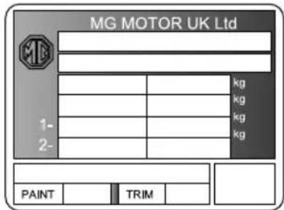
The vehicle identification label contains the following information.
•T ypeApprovalNumber
•VehicleIdentificationNumber(VIN)
•GrossV ehicleWeight
•GrossT rainWeight
•MaxFrontAxleWeight
•MaxRearAxleWeight
- PaintCode
•DieselSmokeLimitValue
•T rimCode
LocationofV ehicleIdentificationLabel

TheVehicleIdentificationLabelislocatedadjacenttothe tophingeontherighthandfrontdoor .
InstrumentsandControls
6InstrumentsandControlsOverview
8 InstrumentPack
10MessageCentre
26 WarningLightsandIndicators
34LightingSwitch
40 WipersandWashers
43SteeringColumn
44Horn
45 Mirrors
48VanityMirror
49Windows
5 | InteriorLight
53 PowerSocket
55 StorageEquipment
57 CupHolder
INSTRUMENTSANDCONTROLS
InstrumentsandControlsOverview

INSTRUMENTSANDCONTROLS
I PassengerAirbag10ElectricExteriorMirrorandWindowControls
2EntertainmentControlFaceplate
II AcceleratorPedal
3InCarEntertainmentDisplay12
BrakePedal
4DirectionIndicators/MainBeamLever | 3IgnitionSwitch
5InstrumentPack
14ClutchPedal
6DriverAirbag
15 GearShiftLever
7Horn
16Heater/AirConditioningControls
8Wiper/WasherControls
17BonnetRelease
9MasterLightingSwitch
INSTRUMENTSANDCONTROLS
InstrumentPack

IEngineCoolantT emperatureGauge
2T achometer
3Speedometer
4FuelGauge
EngineCoolantT emperatureGauge
Theenginecoolanttemperatureisindicatedbythenumber andcolourofsegmentsilluminated(figure 1).
Whenthecoolanttemperatureislow,thefirst(lowest) segmentisilluminatedblue.Whentheengineisoperating atitsnormaltemperature,thefirsttofifthwhitesegments areilluminatedwhite.Whensixthredsegmentis illuminated,thehightemperaturewarningindicator locatedintheinstrumentpackilluminatesandthemessage
HighEngineT empwillappearinthemessagecentre.
Whenthecoolanttemperaturerisesabovethe7th segmenttemperaturethresholdhighcoolant temperaturewarningampviflashimultaneouslywith themessageHighEngineTempappearingagaininthe messagecentre.
Higengincoolantemperatursouldesubevere damage. Stopthevehicleandswitchofftheengineassoon assafetypermitsandseekMGAuthorisedRepaireratthe earliestopportunity.
If the engine coolant temperaturesensormalfunctions, all segmentswillectinguishandtheightemperaturewarning
INSTRUMENTSANDCONTROLS
indicatorwillflashwiththemessageT emperature SensorFaultappearinginthemessagecentre.
T achometer
Indicatesenginespeed(figure2), inrevolutionsper minute(×1000).
IMPORTANT
T oprotecttheenginefromdamage,neverallowthe pointertoremainintheredsectorofthegaugefor prolongedperiods.
Speedometer
Indicatesroadspeed(figure3).
FuelGauge
The quantity offuelinthetankis indicated by thenumber of segmentsilluminated (figure4). There are seven segments intotal. When one segment remains illuminated, the low fuel warning indicator on the righthandside illuminates, with the message Low Fuel appearing in the message centre and a audible warning heard. If the fuel continues
tofalltoacriticalstate,thefuellampwillflashalongwith the lstsegment.TheLowFuelmessagewillappearin themessagecentreandanaudiblewarningwillsoundagain.
IMPORTANT
Ifthelowfuelwarninglightindicatorilluminates,refuel attheearliestopportunity.
If the cluster detects an out-of-range fuelsendervalue when the ignition is in position II, the bottom fuelsegment will flash along with the low fuellamp, with the message FuelSignalError appearing in the message centre.

Anarrownexttothelowfuelwarninglightindicate that thefuelfillerislocatedontherighthandsideofthecar.
INSTRUMENTSANDCONTROLS
MessageCentre

Themessagecentredisplayisinthecentreofthe instrumentpack.Itisdividedintofourzones,containing thefollowinginformation.
IT emperatureandclock
2Gearpositiondisplay/gearchangereminder(if enabled)
3Odometer
4Vehicleinformationdisplay
T emperatureandClock
When the ignition is in position II, the current ambient temperature and time are displayed.
GearPositionDisplay/GearChange Reminder
Gearposition(1,2,3,4,5,6,R,N)isdisplayedinthiszone whenthefunctionisenabled.
Whenagearchangeisadvised,anupordownarrowwill bedisplayedabovethegearposition.T osetthisfunction refertoVehicleInformationDisplay.
Odometer
WhentheignitionisinpositionII, thedisplayshowsthe totaldistancethecarhastravelled.
INSTRUMENTSANDCONTROLS
VehicleInformationDisplay

The vehicle information display contains the following information:
I Warninginformation(figureA)
2T ripcomputermenu(figureB)
3Menu(figureC)
WarningInformation
Thevehicleinformationdisplayusestwomethodsto conveywarninginformationtothedriverTheseare:
Amessageaccompaniedbyasymbol
Arievofthe vehicle with open door bonneor boot/tailgate
Some warning messages are enforced by audible warning.
WarningMessagesandSymbols
T wotypesofwarningmessagesaredisplayed: Messagesre-enforcedbyredbyellowsymbolandthe illuminationofawarninglight.
Messagessupportedbyaredoryellowsymbolonly. Whenfaultsdetectedtheappropriatewarningmessage togetherwithsymbolwillappeainthdisplayThe messagewilldisappearaftersecondsthewarningsnot supportedbywarninglighttheSystemFaultWarningwill displayinyellowworredThestaticsymbolofthewarning cabaccessedyheparationtheripomputer switch.Ifawarningindicatorisalsoilluminated,thiswill remainilluminated,untilthefaultisrectified.
INSTRUMENTSANDCONTROLS
The following messages appear in the message centre but are not supported by dedicated warning lights; instead their status is shown by the System Fault Warning (with the exception of the Beware of lce warning).
| IconMessage | Action | |
 | Beware oflce | Drivecarefully astheroadmay beslippery. |
 | / | Indicatesan openpanel, pleaseclose indicatedpanel. |
 | Engine Disabled | Anincorrect handsethasbeen insertedinthe dockingstation. Theengineis immobilised. Usecorrect handset. |
| IconMessage | Action | |
 | Key Battery Low | See‘Handset Battery Removing and Refitting’in ‘Starting& Driving’. |
 | Overspeed Warning | Slowdownuntil thespeedofthe carisbelowthe setlimit. |
 | Inertia Switch T ripped | See‘Inertia Switch’in ‘Starting& Driving’. |
 | Fuel System Fault | ConsultMG Authorised Repairerat theearliest opportunity. |
INSTRUMENTSANDCONTROLS
| IconMessage | Action | |
 | Low Coolant | See‘Coolant Checkand T opUp’in ‘Maintenance’. |
 | Lamp Failure | Adippedbeam ordirection indicatorbulb hasfailed, replaceat theearliest opportunity. |
 | LightsOn | Switchthelights offbeforeleaving thecar. |
 | Lights offDelay Active forX.X min | Information. |
| IconMessage | Action | |
 | AlarmT riggered | Information. |
 | DoorLocked | Information. |
 | DoorUnLocked/FailToLock | Information. |
 | HeadlampWasherFluidLow | See‘Windscreen andFrontLamp WasherCheck andT opUp’in ‘Maintenance’. |
 | StopStartOn | Stop/Startis initiated. |
INSTRUMENTSANDCONTROLS
| IconMessage | Action | |
 | StopStartOff/StopStartFault | See‘Stop/Start Intelligent System’in ‘Starting& Driving’. |
 | UseKeytoStart | Indicatesthat akeyrestartis required. |
 | CloseDriverDoor | Indicatesthe needtoclose thedriver’s doortoenable theengineto restart. |
| IconMessage | Action | |
 | Fasten Seatbelt to Restart | Indicatesthe needtofasten thedriver'sseat belttoenable theengineto restart. |
 | Head Lamp Control Fault | Indicatedthat AFSsystemhas afault. |
 | Fully Press Clutch | Indicatingthe drivertopress clutch. |
 | Press Brake Pedal | Indicatingthe drivertopress brakepedal. |
INSTRUMENTSANDCONTROLS
| IconMessage | Action | |
 | Clutch Switch Fault | ConsultMG Authorised Repairerat theearliest opportunity. |
 | Select Neutral To Restart | Indicatingthe drivertoselect neutral. |
 | Parking Brake Force Not Enough | ConsultMG Authorised Repairerat theearliest opportunity. |
 | Release EPBby Switch Please | Requestingthe drivertorelease theEPBusing theswitch. |
| IconMessage | Action | |
 | Gradient High | Indicating gradientishigh. |
 | Press Brake Release EPB | Indicatingtothe drivertheneed topressthe braketorelease EPB. |
 | Front Brake Pads Worn /Rear Brake Pads Worn | ConsultMG Authorised Repairerat theearliest opportunity. |
 | HillHold Unavaliable | Indicatinghill holdiscurrently unavailable. |
INSTRUMENTSANDCONTROLS
| IconMessage | Action | |
 | Caution !Wheels not Straight | Requestingthe drivertoadjust thesteering wheel. |
 | Caution !Wheels not Straight | Requestingthe drivertoadjust thesteering wheel. |
 | Limited Engine Power | ConsultMG Authorised Repairerat theearliest opportunity. |
 | Vehicle Network Fault | ConsultMG Authorised Repairerat theearliest opportunity. |
| IconMessage | Action | |
 | / | Requestingthe drivertochange gearindirection ofarrow. |
 | Diesel Particle Filter | ConsultMG Authorised Repairerat theearliest opportunity. |
 | Waterin Fuel | Indicatesthat thefuelwater filterisfull andrequires emptying. |
Door,Bonnet,BootOpenIndicator
Ifanydoororbonnetorbootisopenedwhentheignition isswitchedon,aplanand(or)sideviewofthecarwill displayed.Itwilldisappearfter3seconds,lf,however
INSTRUMENTSANDCONTROLS
oneormoredoors,orthebonnetarenotclosedwhen vehiclespeedexceeds3MPH(5km/h),thiswarningwillbe repeatedinthedisplay.
T ripComputer

When the ignition is in position II, the different trip computer functions can be selected as follows:
- Lowlinemodels(A):Shortpress(<2seconds) thebuttonontheendofthedirectionindicators/main beamlevertoselectthetripcomputerfunction.Usea longbuttonpress(>2seconds)toenterthemenufrom thetripcomputerortoenterahighlightedfunction.
- Highlinemodels(B):Usetheleft-hand thumbwheeltoscrollupandscrolldowntoselectthe tripomputefunctionbhighlighmenitem. Presshleft-handumbwheelentethmenu fromthetripcomputerortoenterahhighlightedmenu item.
The following information will be displayed.
- NextService
•DigitalSpeed
•FuelConsumption
•RangetoEmpty(distancetotankempty)
•AverageFuelConsumption
•AverageSpeed
•T ripl
•T rip2
•LapTime - CurrentJourney
INSTRUMENTSANDCONTROLS
- LastJourney
Bypassingandholdingthebuttonorthumbwheelfor longerthan2seconds,theselecteddisplaycanbereset (notincludingdigitalspeed,fuelconsumption,rangeto empty,lastjourney).Whenatripcomputerfeatureis selected,itwillbedisplayeduntilthenexttripcomputer functionisselectedoruntilanotherfeatureisselected.
Note: If a warning message is received while the trip computer is in use, the trip display will be replaced by the warning message. After display for 3 seconds, it will automatically return to the previous screen.
Note: Any of the Options can be disabled, so that the driver cantail orthelist of available information to suit individual preferences.
NextService
Themessagecentreshowsthedistanceremainingbefore thenextserviceisdueandtheestimateddatethatitwill bedueon.Thisdisplayappearsfor4secondseverytime theignitionisswitchedtopositionll.
Thedistancedisplaycommencesat15,000milesor24,000kmandprogressivelyreducesinincrementsof25miles or50kmasthecarisdriven,untilzeroisreached.The relevantserviceshouldbecarriedassoonasthedistance displayshowszero.Afterthecompletionofeachservice,thedistancedisplaywillberesetto15,000milesor24,000km.
Note: Because the service interval display reduces in increment of 25 miles or 50 km, it is possible to undertake short journey without triggering any movement from the display.
Aservices avomindlstanace time-related intervalsof 15,000miles/24,000kmor 12months.
Note: If a service is not carried out (orthedisplay is not reset), the distance indicator, having reached zero, will remain at zero until it is reset.
DigitalSpeed *
Thedigitalspeeddisplayfunctionisautomaticanddisplays thecurrentvehiclespeed.
INSTRUMENTSANDCONTROLS
FuelConsumption
This function is automatic and indicates the instantaneous fuel consumption.
RangetoEmpty
Thisfunctionisautomaticanddisplaystheremaining distanceyoucantravelbeforethefuelgaugereadsempy. Thedistancewillchangewhenthevehicleisrefuelled.
The 'rangetoempty' calculation is based on a combination of current driving style and the fuel consumption recorded by the computer during the previous few minutes.
AverageFuelConsumption
Averagefuelconsumptioniscalculatedbydividingthe amountoffuelusedbythedistancetravelledsincelast reset. Theconsumptionvaluecanberesetatanytimeto begincalculatingnewconsumptionvaluesforaparticular journeyordrivingconditions.
Note: Average fuel consumption is related to driving habits, road condition, load, tyre pressure, the quality of oil, etc.
AverageSpeed
Thisfunctionisautomaticandindicatestheveragespeed sincethelasttimeitwasreset. Theaveragespeeddisplay canberesetatanytimetobegincalculatinganewaverage speedvalueforaparticularjourneyordrivingcondition.
Trip1, Trip2
Thisfunctiondisplaysthetriprecordersincethelasttime itwasreset.Trip1andtrip2areindependent.
LapTime
Thisfunctiondisplaysthetimesincelastreset. Thelaptime displaycanberesetatanytimetobegincalculatinganew laptimevalueforaparticularjourneyordrivingconditions. Byeitherashortpressonthebuttonorashortpressof thumbwheel,thelaptimedisplaycanbestoppedorcarry on.
CurrentJourney
This function is automatic and display the duration, the cumulative value of fuel consumption, and distance values for the current journey. The current journey values can
INSTRUMENTSANDCONTROLS
beresetatanytimetobegincalculatingnewvaluesfora particularjourneyordrivingconditions.Italsocanbereset automaticallyafterthevehiclehasbeenatrest(speed<3 MPHor<5km/h)for30minutes.
Duringtheresetprocess, the data values for the current journey function are saved for use by the last journey function.
LastJourney
Thisfunctionisautomaticanddisplaystheduration, distanceandfuelvaluesforthelastjourney. Thesevalues areautomaticallyoverwritteneachtimeacurrentjourney resettakesplace. TheLastJourneydataisonlyresetby theglobaltripcomputerresetfunction.
Menu

WhentheignitionisinpositionII,accessthemenuby selectingandholdingthebuttonformorethan2seconds (Lowline)orsimilarlypressingthethumbwheel(Highline).
Selectionswithinamenuaremadebybrieflypressingthe buttonorrotatingthethumbwheeluntilyourchoiceis highlightedandthenpressingandholding.
Thismenuoffersthefollowingselections:
-Presstoreturntothepreviousmenu.
INSTRUMENTSANDCONTROLS
•SpeedWarning
- NextService
- FunctionReset
- TPMSReset
•VehicleOptions
SpeedWarning
Forlowlinemodels, pressandholdthebuttontosetthe speedwarning. Repeatedlypressthebuttontoselectyour desiredspeed. Thespeedwillchangeinincrements of 5MPH(or5km/h)foreachbuttonpress.Speedrangeis 5-120MPH(or5-190km/h).Select toreturnto upperlevelmenu.
Forhighlinemodels, themenudisplaysthecurrentsetting speed, ‘+’ and ‘-’ sign. Rotatethethumbwheelup (increase) ordown (decrease) tochangethespeedas required. Speed range is 5-120 MPH (or 5-190 km/h). Thespeed will change in increment of 5 MPH (or 5 km/h). Select to return upper level menu.
Whenspeedwarningisactive,themessageSlowDown andanaudiblewarningwillindicatetothedriverthatthe speedofthecareexceedsthelimitset.
SpeedWarningfunctioncanbeset'off'asrequired.
NextService
Showstheserviceintervalannouncementsymbol,the estimated data the service and distance remainingwhicheverissoonerbeforeitshouldbecarried out.
ToresetservicinformationselecResetherpress andholdthebuttonorthelefthandthumbwheeluntilthe displayeddistancereads15000milesor24000km.
FunctionReset
ToesetheriprecordereadingselectTripTrip 2AveragFueAveragSpeedAllthen pressandholdthebutton(lowlinecars)orthelefthand thumbwheel(highlinecars)toesSelect to returntoupperlevelmenu.
TPMS(TyrePressureMonitoringSystem)Reset SelectEPM@esetnen@thepresandoldTPMS Reset.Thiswillinitialisethesystem.Ifsuccessful,TPMS
INSTRUMENTSANDCONTROLS
ResetOKwillappearandifunsuccessful,TPMSReset Failedwillappear,consultyourMGAuthorisedRepairer.
Note: TPMSwillneedtobereset everytimethetyres arereplacedorthepressuresarechanged.
Note: The TPMSresetmenuwillonlybeavailable whenthecarisstationary, with the parkingbrake applied and ignitioninposition //. //
Note: ATPMSresetwillbecompletedafterthevehicle hastravelledtotalof1hourormoreataroadspeed greaterthan6MPH(10km/h).
VehicleOptions
IntheVehicleOptionsmenu,youcanconfigure some features on the followingsystems or settings.
Note: The vehicle options menu will only be available when the car is stationary, with the parking brake applied and ignition in position //. //
Security
Allowspersonalisationofthespeedlockingfunctionand unlockingfunction.
SpeedLocking
PressandholdSpeedLockingtherselectOnOff asrequired.Selecttoretwntoupperlevelmenu.
Unlocking
PresandHold Unlocking theselecAldoors DriverOnlyasrequired.Select ← toreturntoupper levelmenu.
ProgWashWipe
Enableordisableprogrammedwashwipe.Pressandhold Of6 Onelear topperevelhenu. Pleasereferto'ProgrammedWashWipe'inthischapter.
Units
Setstheunitsofmeasurementforconsumptionand distance.
INSTRUMENTSANDCONTROLS
Consumption
SeleceitheL/10kmkm/LMpg(US)Mpg (UK).Selecttoreturntoupperlevelmenu.
Distance
Select Miles on km Select at top level menu.
LightsOffDelay
SetstheLightsOffDelayfunction.Allowsthedriver toselectilluminationoffrontlights(headlampdipped beams)and/orrearlights(rearfogguardlamps)orboth. Inaddition,thedurationthatthelightsareilluminatedcan bedefined.
SelectFront followed by FrontOn FronOff. Presstoreturntoupperlevelmenu.
Select Rear followed by Rear On or Rear Off Press toreturntopowerlevelmenu.
T osettheduration,selectDuration.Thecurrent durationwillbedisplayed.Press‘+’or‘-’tochangethe durationasrequired.Adurationofupto5minutesin
incrementsof30secondscanbeselected.Selectto returntoupperlevelmenu.

FindMyCar *
Enableordisableautomaticilluminationofnominated exteriorlampsforaspecificduration,whenunlocking thecarwiththehandset.Thiswillassistthedriverin locatingthecarinbusycarparks. Thedrivercanselect illuminationoffrontlights(headlampdippedbeams),rear lights(rearfogguardlamps)orboth.
SelectFrontfollowedFronOnFronOff. Select ← toreturntoupperlevelmenu.
SelectRearfollowed by RearOni RearOfSelect toreturntoupperlevelmenu.
T osettheduration,selectDuration.Thecurrent durationwillbedisplayed.Press'+'or'-'tochangethe durationasrequired.Adurationofupto5minutesandin incrementsof30secondscanbeselected.Select returntoupperlevelmenu.
INSTRUMENTSANDCONTROLS
Language
SelectEnglish, | | | | | | | | | | | | | | | | | | | | | | | | | | | | | | | | | | | | | | | | | | | | | | | | | | | | | | | | | | | | | | | | | | | | | | | | | | | | | | | | | | | | | | | | | | | | | | | | | | | |
EspañoPortuguêsahlinguagóhe
displayedtextformessagecentre.Select toupperlevelmenu.

SpeedWarning
PresandoSpeeWarning,hereledOff
or Manual to set the operational mode of the speed warning. If manual mode is selected, the manual set point will be adopted asthreshold to activate the overspeed warning.
Selecttoreturntoupperlevelmenu.
GearDisplay
Enableordisablethegeardisplayfunction.Pressand holdGearDisplaytheselectOnOffs required.
Selecttoreturntoupperlevelmenu.
DialSweep
Enableordisablethestart-updialsweepfunctioninthe clusterPresandolDiaSweeptheselecOn
orOffasrequired.Selecttoreturntoupperlevel menu.
GearChange
Enableordisablethegearchangewarningfunction.Press andolGeaChangehenelecOf6Ecor
SportasrequiredSettortoupperlevel menu.
TripComputer
SebriopomputedisplayeDefault
Functions.Select ↩ toreturntoupperlevelmenu.
Select Default, the selected History Blanks
requiredSelectntoupperlevelmenu.
Select Functions scale DigitSpeed,
Instantaneous Fuel Range Empty Average
FuelAvSpeedTripLapTimeCurrent
INSTRUMENTSANDCONTROLS
Journey:LastJourneysrequiredSelectreturntoupperlevelmenu.

AdaptiveFrontlightingSystem(AFS) *
EnableordisabletheAFSfunction.PressandholdAFS, therelecOnOffrequiredSelectn toupperlevelmenu.
DigitalClock
Thisallowsthesettingofthedigitalclockifnosignalis availablefromtheincarentertainmentsystem.
PressandholdDigitalClock,therselectHourorMin asrequired.
This menu will not appear when a signal is available from the incarentertaintiesystem.
INSTRUMENTSANDCONTROLS
WarningLightsandIndicators

PASSENGER AIRBAG
OFF

ON

INSTRUMENTSANDCONTROLS
MainBeam-Blue

Illuminateswhentheheadlightsareswitchedtomainbeam.
SideLamps-Green

Illuminateswhenthesideorheadlightsareswitchedon.
DirectionIndicators-Green

The left and right direction indicators are represented by directional arrows located at the top of the instrument display. The warning lights flash synchronised with the exterior left or right direction indicator lights whenever they are operating.
If the hazard warning lights are operated, both warning lightswillflashtogether.
Ifeitherwarninglightflashesveryrapidly,thismeansthat oneofthefrontorreardirectionindicatorlightsisnot operating.
Note: Failureofasiderepeaterlightwillhavenoeffect onthewarninglightflashfrequency.
RearFogGuardLight-Yellow

Illuminateswhentherearfogguardlightsareswitchedon.
SRSWarning-Red

The warning lightilluminates whentheignitionisin positionllandextinguishesafterafewseconds. If the lightilluminatesatanyothertimeorfailstoextinguish afterstartup, anairbagrestraintsystemfaultorseatbelt pre-tensionersfaulthasbeendetected, then Airbag Fault and awarningiconwillappearinthemessagecentre
INSTRUMENTSANDCONTROLS
andanaudiblewarningwillbegivenwhentheengineis started.SeekanMGAuthorisedRepairerurgently.
SeatBeltWarning-Red

WhentheignitionisinpositionII,ifaseatbeltforan occupiedfrontseatremainsunfastened,thelampwillturn on.
If these seat belt for an occupied seat remains unfastened on the vehicle forwards speed has exceeded 3 MPH (5 km/h), the warning lamp will flash accompanied by an audible warning, the message Fasten Seat Belt Please Faster Passenger Seat Belt will appear in the message centre.
The warning will continue until either these at belt is fastened correctly or reverse gear is selected. On stop/start vehicle the warning will continue until these at belt is fastened correctly, reverse gear is selected, or 90 second shas expired.
CruiseControl-Y ellow/Green*

Thelightilluminatesgreenwhenthemasterswitchis pressedbutnocruisespeedisactiveandyellowwhen cruisecontrolisactive.Themessagecentrewilldisplay CruiseSet###MPH(###representsthespeedset) or CruiseControl:Standbyasappropriate.lfa faultisdetected,thewarninglightwillflashyellowandthe message CruiseControl:Faultwillbedisplayed.
LowOilPressure-Red

Illuminatesredasalampcheckwhentheignitionisin positionllandextinguisheswhentheengineisstarted.If thelightremainson(accompaniedbythemessageLow OiPressure)orilluminatescontinuouslywherdriving, seriousenginedamagecouldoccur;stopthevehicleas soonassafetypermitsandSWITCHOFFTHE ENGINEIMMEDIA TELY.Checktheoillevel.Seek anMGAuthorisedRepairerurgently.
INSTRUMENTSANDCONTROLS
AlternatorChargeWarning-Red

Thelightilluminatesredasalampcheckwhentheignition isinpositionIandextinguishesassoonastheengine isrunning.Ifthelightremainson(accompaniedbythe messageAlternatorFail),orilluminateswhendriving, itindicatestothedriverthatthechargingoutputfromthe alternatortothebatteryislow.SeekanMGAuthorised Repairerurgently.
T yrePressureMonitoringSystem(TPMS)
Warning-Y ellow

Thelightilluminatesyellowwhentheignitionisinposition II. Itextinguishesafterafewseconds. If thereislowtyre pressuredetected, theightilluminatesyellowandLow T yrePressurewillappearinthemessagecentre. Check for lowtyrepressure/flattyre, adjustyourtyrepressures orseekanMGAuthorisedRepairer.
Ifthereisafaultwiththesystem,thelightwillflashfor about90secondsthenremainson.T yrePressure SystemFailwillappearinthemessagecentre.Seek anMGAuthorisedRepairer.
StabilityControlSystemTractioControl OperationandFaultWarning-Yellow
Thelightilluminatesyellowasalampcheckwhenthe ignitionisinpositionlandextinguishesafterafew secondlfthereisafaultwiththesystem,thewarning lightwillilluminatewhenthecarisbeingdriven.The messagecentrewilldisplayStabilityControlFailor T ractionControlFailasappropriate.Stopthecar assoonassafetypermitsandcontactMGAuthorised Repairerforinspectionatyourearliestconvenience.Ifthe warninglightflashesduringdriving,thisindicatesthatthe systemmistakingcontroltoassistthedriver.
INSTRUMENTSANDCONTROLS
StabilityControlSystem/T ractionControlOff
Warning-Y ellow

Thelightilluminatesyellowasalampcheckwhenthe ignitionisinpositionIandextinguishesafterafew seconds.Ifthestabilitycontrolsystemortractioncontrol systemareswitchedoff,thewarninglightwillilluminate. ThemessageStabilitControlOffTraction ControlOffwillappearinthemessagecentre.
ABSWarning-Y ellow

Thelightilluminatesforafewsecondsasalampandsystem checkwhentheignitionisinpositionII.Ifthelightdoesnot extinguish,andABSFailappearsinthemessagecentre, thenafaulthasoccurredwiththeABSsystemandyou shouldseekanMGAuthorisedRepairerattheearliest opportunity.
IfanABSfaultoccurswhiledriving,ABSoperationwillbe suspended,butnormalbrakingwillstillbeavailable.Seek anMGAuthorisedRepairerattheearliestopportunity.
BrakeSystemWarning-Red

This red warning light will illuminate for a few seconds as a lamp check when the ignition is in position II.
If the warning light remains illuminated after lamp check, a fault with the brakes system is indicated - them message BrakeFail will appear in the message centre. Check the brake fluid level (See 'Brake Fluid in Maintenance'). If the light continues to illuminate stop the car as soon as safety permits and seek an MGA authorised Repairer urgently.
CheckEngine/DrivebyWireWarning-Y yellow

This warning light is used to indicate an engine operation fault is detected by the engine managements system. The
INSTRUMENTSANDCONTROLS
indicatorilluminatesasasystemcheckwhentheignitionis inpositionllandshouldextinguishafterafewseconds.
Ifanon-emissionsrelatedfaultoccurswhilethevehicleis beingdriven,theindicatorwillilluminateandthemessage CheckEnginewillappearinthemessagecentre.Seek anMGAuthorisedRepairerurgently.
MalfunctionIndicatorLampWarning-Y yellow

This warning light is used to indicate an emission related fault is detected by the engine management system. The indicator illuminates as a system check when the ignition is in position and should distinguish when the engine is started.
Ifanengineoperationproblemoccurswhilethevehicleis beingdriven,theindicatorwillilluminateandthemessage EngineFaultwillappearinthemessagecentre.Seekan MGAuthorisedRepairerurgently.
ElectronicHydraulicPowerAssistedSteering (EHPAS)/ElectronicSteeringColumnLock (ESCL)/SteeringAngleSensor(SAS)Warning-Red

This red warning light willilluminate for a few seconds as a lamp check when the ignition is in position 11.
The warninglightisusedtoindicatetothedriverthata faultexistsinelectronichydraulicpowerassistedsteeringorelectronicsteeringcolumnlocksystemorsteeringangle sensor.
IfEHPAShasafault, the warning light willilluminate and the message centrewill display Power Steering Fault. Seekan MGAuthorised Repairerurgently.
IfESCLhasafault, the warninglightwillilluminate and the message centrewill display Steering System Fault. Seekan MGAuthorised Repairerurgently.
If SAShasafault, themessagescreenwill display SAS Fault. If SAS is not calibrated, the messagescreen will
INSTRUMENTSANDCONTROLS
displaythepromptmessageSASUncalibrated.Seek anMGAuthorisedRepairerurgently.
EPBStatusWarning-Red

When the EPB is engaged thered warning light illuminates. If a fault occurs with the EPB switch the warning light will flash.
EPBFaultWarning-Y ellow

This yellow warning light indicates a fault with the EPB, that the EPB is in a diagnostic state. Warning lamp illumination is accompanied by an audible alarm.
Stop/StartActiveIndication-Green

This warning light will illuminate for a few seconds as
lampcheckwhentheignitionisinpositionII. Thewarning lightilluminatesgreentoindicatetothedriverthatthe engineisbeingcontrolledbystopstartsystem.When StopStartfunctionisinhibited,thelightwillextinguish afterflashing3times,andthemessageStopStart CurrentlyUnavailablewillappearinthemessage centre.
SystemFaultWarning/AlarmStatusWarning-Yellow/Red

Thiswarninglightisusedtoindicatetothedriverthestatus ofanynon-tell-talewarnings. Thisisabi-colouredwarning lampilluminatedineitherredoryellowdependingupon whatwarningscurrentlyexist. Thelampisilluminatedred ifaredwarningexists. Thelampisilluminatedyellowifa yellowwarningexists.lfbothredandyellowwarningsexist simultaneously, thentheLEDisflashedalternatelyredand thenyellowat2secondintervals.
Whenignitionisoff, the warninglight provides information about the status of the alarms system. Please seem more
INSTRUMENTSANDCONTROLS
informationin'LockingtheCarandArmingtheAlarm'in 'Starting&Driving'.
GlowPlugWarning-Y ellow

The warning light illuminates yellow. The glow plug warning is used to indicate the driver that the diesel engine glow plugs are still heating and below their cut-off temperature threshold, above which the engine may be cranked.
PassengerAirbagOff-Y ellow

The warning light is located on theremoted display module and is used to indicate that the passenger air bag has been disabled. If the passenger air bag has been disabled, the light will remain illuminated until the air bag is enabled, and the message Passenger Air bag Off will appear in the message centre. On the passenger air bag has been enabled, the light will extinguish and the message
PassengerAirbagOnwillappearinthemessage centre.
Note: Theremotedisplaymodule is mounted on the roof.
PassengerAirbagOn-Y ellow

The warninglightislocatedontheremotedisplaymodule andisusedtoindicatethatthepassengerairbaghasbeen enabled.Ifthepassengerairbaghasbeenenabled,the lightwillremainilluminateduntiltheairbagisdisabled, andthemessagePassengerAirbagOnwillappear inthemessagecentre.Oncethepassengerairbaghas beendisabled,thelightwillextinguishandthemessage PassengerAirbagOffwillappearinthemessage centre.
Note: Theremotedisplaymoduleismountedonthe roof.
INSTRUMENTSANDCONTROLS
LightingSwitch
MasterLightingSwitch

IAUTOLights
2Side, tailandlicenceplatelights
3Headlights
AUTOLights *
Withtheignitionswitchedon,turnthemasterlighting switchtoAUTOposition(1).TheAUTOlighting systemconstantlymonitorstheambientlightlevelsand automaticallyswitchesthedippedheadlamps,sidelight, taillightsonandoffasrequired.
Side,T ailandLicencePlateLights
T urnthemasterlightingswitchtoposition(2),toswitchon theside,tailandlicenceplatelights.Thesidelightwarning lightwillilluminateandSidelightsOnwillappearinthe messagecentre.Ifthelightsarestillswitchedonwhenthe ignitionhandsetisremovedandthedriver'sdoorisopened,anaudiblewarningwillbegivenandLightsOninformation willbedisplayedinthemessagecentre.
Headlights
Withtheignitionswitchedon,turnthemasterlighting switchtoposition(3),toswitchontheheadlights.
INSTRUMENTSANDCONTROLS
HeadlightCourtesyDelay
Havingstoppedthecarandturntheignitionoff. Then movethedirectionindicatorlevertothemainbeam position. Theheadlightsandrearfogguardlightswill remainilluminatedforyousetting. Forinformationon configuringtheLightsOffDelay, see 'Menu' of 'Message Centre'.
DaytimeRunningLights
Thedaytimerunninglightsturnonautmaticallywhen theignitionswitchisinpositionII.Whenthesideor headlightsareswitchedon,thedaytimerunninglightsare extinguished.
InstrumentDimmerControl
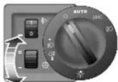
Whentheignitionisinpositionll,andthesidelampsordippedheadlampsareon,rotatethecontroluptoincreaseordowntodecreaseinstrumentillumination.Theinstrumentdimmeralsocontrolsthebacklightilluminationofswitches,audiosystem,messagecentreandthesatellitenavigationsystem(iffitted).Whenthesidelightsareswitchedonthemessagecentredisplayontheinstrumentpackandthesatellitenavigationsystem(iffitted)willdimautomatically.
ManualAdjustmentHeadlightLevelling *

The angle of the dipped beam is affected by the distribution of passenger and luggage weight within the car.
To ensure correct headlampaim, and not dazzleon-coming traffic, the headlamplevelling switch positions should be
INSTRUMENTSANDCONTROLS
adjusted according to the vehicle loading condition in accordance with the following table:
| Position | Load |
| 0Driver,ordriver&frontpassenger | |
| 1 | Alltheseatsoccupiedwithnoload |
| 2 | Alltheseatsoccupiedplusanevenlydistributedloadintheboot,achievethegrossvehicleweight |
| 3 | Driveronly,plusanevenlydistributedloadintheboot,achievethegrossvehicleweight |
DynamicHeadlampLevelling *
DynamicHeadlampLevellingispartoftheAdaptive FrontlightingSystem(AFS).Withthedippedbeam headlampsswitchedon,vehiclesfittedwiththeDynamic HeadlampLevellingsystemwillautomaticallyadjustthe headlampaimaccordingtovehiclespeed,acceleration, decelerationandunevenroadsurfaces.
CorneringLamps *
CorneringLampsarepartoftheAdaptiveFrontlighting System(AFS).Illuminationofdriverblindspotswhen corneringisachievedbyaddingextralightstothe traditionalheadlamps.
Whentravellingforwards,thedippedheadlampsare switchedon,vehiclespeedisbelow25mph(40kph)and thesteeringwheelisrotatedinexcessof30degrees,the correspondingcorneringlampwillilluminate.Ifreversing, thecorneringlampoppositethesteeringwheelrotational directionwillilluminaFarAFSconfigurationplease referto'MessageCentre'inthe'InstrumentandControls' section.
INSTRUMENTSANDCONTROLS
FogLights

Foglightsshouldonlybeusedinpoor visibility,inappropriateusecoulddazzle otherdrivers.

Note: Therearfoglightsareswitchedoff automaticallywhenthemainlightingswitchisturned off.
RearFogLights
WhentheignitionisinpositionII, lightsareswitchedon, pullthelightswitchouttopositionI toswitchontherear foglights. Thewarninglightintheinstrumentpackwill illuminatewhenthefoglightsareon.RearFogLampsOn willappearinthemessagecentre.
INSTRUMENTSANDCONTROLS
DirectionIndicator/MainBeamLever

T akecarenottodazzleoncomingvehicles whendrivingusingmainbeamheadlights.

DirectionIndicators
Movetheleverdown(1)toindicateaLEFTturn,orup (2)toindicateaRIGHTturn.ThecorrespondingGREEN warninglightintheinstrumentpackwillflashintimewith thedirectionindicators.
T oindicatealanechange, presstheleverbriefly and release, the indicators will flash three times and then cancel.
HeadlightMainandDippedBeam
WhentheignitionisinpositionII, dippedheadlamps switchedon, pushtheleverawayfromthesteeringwheel (3) to switch on main beam. The BLUE warning light in the instrument pack illuminates, Main Beam On appears in themessage centre. Push the lever away from the steering wheel (3) againtoswitchoff Main Beam headlamp.
HeadlightFlash
T obrieflyflashthemainbeamonandoff,pullthelever towardsthesteeringwheel(4)andthenrelease.
INSTRUMENTSANDCONTROLS
LampFailure
Failureofanyofthefollowingbulbswillbeconfirmedbya messageandsymbolinthemessagecentre.
- Frontdirectionindicator.
- Reardirectionindicator.
•Dippedbeamheadlamps.
Note: Thesidelamps, siderepeaterlamps and centre highmounted stoplamp are not monitored by this system.
HazardWarningLights
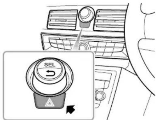
Presstheswitchtooperatethehazardwarninglights. All thedirectionindicatorsanddirectionindicatorwarning lightswillflashtogether.Pressagaintoswitchoffandthe directionindicatorsanddirectionindicatorwarninglights willturnoff.
INSTRUMENTSANDCONTROLS
WipersandWashers
IMPORTANT
- Avoidoperatingthewipersonadryscreen.
• Infreezingorveryhotconditions, ensure that the blades are not frozen or stuck to the glass before being operated.
• Inwinter, removesnoworicefromaroundthearms andblades, includingthewipedareaofthescreen.
FrontWindscreenWiperControls
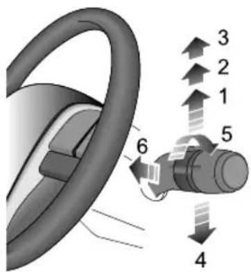
Thewipersandwasherswilloperatewiththeignitionin positionl,i.e.Auxiliary.Pushtheleveruptoselect differentwiperspeeds.
•Intermittentwipe/Automaticwipe * (1)
•Normalspeedwipe(2)
•Fastspeedwipe(3)
INSTRUMENTSANDCONTROLS
•SingleWipe(4)
•WiperDelaySwitch(5)
•ProgrammedWash/Wipe(6)
Intermittentwipe/Automaticwipe *
Pushthelever(1)uptoselecttheintermittent wipe/Automaticwipe *,wiperswillwipeautomatically. Rotatetheswitch(5)tovarytheintermittenttimeof wiperoperation.Intermittentoperationtimeofwipers willalsobeamendedaccordingtoroadspeed-increased roadspeedwillreduceintermittentoperationtime.
NormalSpeedWipe
Pushthelever(2)uptoselectthenormalspeedwipe, wiperswillwipeatnormalspeed.Iftheroadspeeddrops below8km/hwhilethewipersareoperating,theywill slowtothenextslowestoperatingmode;i.e.fastwipe tonormalwipe,normalwipetointermittent.Thisfacility canbemanuallyoverriddenbychangingthewipesetting.
FastSpeedWipe
Pushthelever(3)uptoselectthefastspeedwipe,wipers willwipeathighspeed.Iftheroadspeeddropsbelow8 km/hwhilethewipersareoperating,theywillslowtothe nextslowestoperatingmode;i.e.fastwipetonormalwipe, normalwipetointermittent.Thisfacilitycanbemanually overriddenbychangingthewipesetting.
SingleWipe
Pullthelever(4)downandrelease,wiperswillwipeonce. Iftheleverishelddown,thewiperswilloperateathigh speeduntiltheleverisreleased.
ProgrammedWashWipe
Pullthelever(6)towardsthesteeringwheel-thewashers operateimmediately.Afterashortdelay,thewiperswill commenceoperatinginconjunctionwiththewashers, bothfunctionscontinuinguntiltheleverisreleased.The programmedwashwipefunctioncanbedisabled;referto section'ProgWashWipe'of'MainMenu'intheChapter 'MessageCentre'.
INSTRUMENTSANDCONTROLS
IMPORTANT
Ifthewashersfailtodeliverthescreenwashsolution (dirtoricemayhaveblockedthejets), releasethe leverimmediately. Thiswillpreventthewipersfrom operating, and the consequentriskofvisibility being impaired by dirtsmearing acrosstheunwashed windscreen.
HeadlampWashers *
CarsequippedwithHIDheadlampsfeatureheadlamp washers,thesearelocatedinthebumper.
Afterswitchingontheheadlamps, the first use of the screenwashers will initiate a headlamp wash. After this, every fourth screen wash will result in single headlamp wash.
RainSensor *
Somemodelsareequippedwitharainsensorfittedto theinsideofthewindscreenbehindtherearviewmirror. Thesensorisabletodetectvaryingamountsofwateron theoutsideofthewindscreen.Withthewipercontrol
settointermittent, thevariabledelaywillbeadjusted automaticallyaccordingtotheinformationsuppliedbythe rainsensor.
Note: If the sensor detects constant train, the wipers will operate continuously. The sensitivity of the sensor can be altered by means of the wiper variable delay.
INSTRUMENTSANDCONTROLS
SteeringColumn
SteeringColumnAdjustment

Donotattempttoadjusttheheightorangle of thesteeringwheelwhilethecarisin motion. This is extremely dangerous.

T oadjusttheangleandheightofthesteeringcolumnto suityourdrivingposition:
I Fullyreleasethelockinglever.
2Holdthesteeringwheelinbothhandsandtiltthe steeringcolumnupordowntomovethewheelinto themostcomfortableposition.
3Pullorpushthesteeringwheelcloserto,orfurther awayfromyourbody.
4Onceaccomfortabledrivingpositionhasbeenselected, pullthelockingleverfullyuptolockthesteering columnintoitsnewposition.
INSTRUMENTSANDCONTROLS
Horn
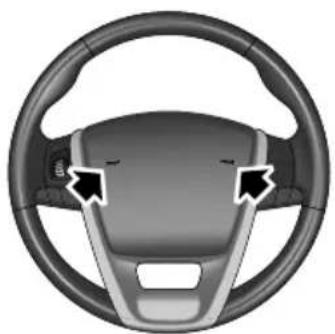
Whentheignitionswitchisinpositionlorll, pressthe steeringwheelpadwherearrowedtooperatethehorn.
Note: The vehicle horn press and the driver's airbag are located in close proximity on the steering wheel. The illustrations show the position of the horn,
pleaseensurethatyoupressinthisareatoavoidany potentialconflictwiththeoperationoftheairbag.
IMPORTANT
T oavoidpossibleSRSissues, pleasedonotpresswith excessiveforceorhittheairbagcoverwhenoperating thehorn.
INSTRUMENTSANDCONTROLS
Mirrors
ExteriorMirrors
Note: Objectsviewedinexteriormirrorsmayappear furtherawaythantheyactuallyare.
MirrorGlassAdjustment

- WiththeignitioninpositionlorII,press the appropriateswitch(I)toselecttheleftorrightmirror. Theselected(L)or(R)buttonwillbeilluminated.
- Useswitch(2)totiltthemirrorglassup/down/leftor right.
- Useswitch(I)againtodisabletheswitchandprevent inadvertentlymovingthemirrorglass.
HeatingElements *

Thedoormirrorshaveintegralheating
elementswhichdisperseiceormistfromtheglass.The heatingelementsoperatewhiletheHeatedRearWindow isswitchedon.
Note: The heated rear window and mirror heating elements only work while the engine is running.
MirrorFolding
The body of each doom mirror is designed to fold that against the side of the caron impact.
INSTRUMENTSANDCONTROLS
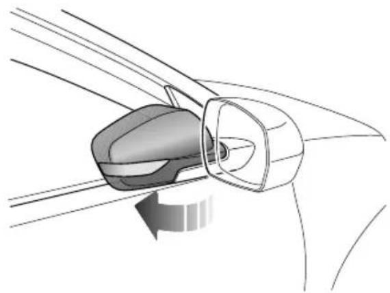
Themirrorscanalsobefoldedbackmanuallytowardsthe sidewindowsintoa'park'positiontoenablethecarto negotiatenarrowopenings,orwhenparked.
IMPORTANT
•Theexteriormirrorglassiselectronicallyadjusted usingthemirrorswitch,DONOTattempttoadjust themirrorglassbyhand,thiscouldresultindamage totheadjustmentcomponents.
- Exteriormirrorsareoperatedwithmotors. Therefore,flushingwithhighpressurewaterjets directlyinthecarwashmayresultinthefailureof theelectricdevice.
INSTRUMENTSANDCONTROLS
InteriorRear-viewMirror
Beforedriving,adjustthebodyofthemirrorbyhandto achievethebestpossibleviewtotherear. Thedipping functionofboththeautomaticandmanualmirrorshelps toreduceglarefromtheheadlightsoffollowingvehiclesat night.
AutomaticMirror *

Theinteriormirrorisequippedwithalightsensor (arrowed)whichactivatestheautomaticdippingfunction, whenafollowingvehicle'sheadlightscoulddazzlethe
driver. The automaticdippingfunctionisinhibited when reversegearisselected.
ManualMirror *

Movetheleveratthebaseofthemirrorforwardto'dip' themirror.Normalvisibilityisrestoredbypullingthelever backagain.
Note: In some circumstances, the view reflected in 'dipped' manual mirror can confusethedriver as to the precise location off following vehicles. Remember to take additional care.
INSTRUMENTSANDCONTROLS
VanityMirror

Thedriver'svanitymirrorshouldonlybe usedwhenthecarisstationary.

Pivotthesunvisor(1) downward and open the cover to use the vanity mirror(2).
INSTRUMENTSANDCONTROLS
Windows
PowerOperatedWindowSwitch

IFrontRightWindowSwitch
2FrontLeftWindowSwitch
3RearRightWindowSwitch
4RearLeftWindowSwitch
5RearWindowIsolationSwitch
WindowOperation
Ensurechildrenarekeptclearwhenraisingor loweringawindow.
Pushtheswitch(1-4)downtolower,andpulltheswitchup toraisethewindow.Thewindowwillstopmovingassoon astheswitchisreleased(unlessthe'One-T ouch'function isactive).
Note: The front and rear passenger windows can also be operated by individual window switches, mounted oneachdoor. Therear window switches will not be operated if therear windowisolations switch has been activated.
Note: The electric window can be operated with the ignition in position / or // (Forsafety: door should be closed).
RearWindowIsolationSwitch
Pressthebutton(5)toisolatetherearwindowcontrols (anindicatorlightinthebuttonilluminates),pressagainto restorecontrol.
INSTRUMENTSANDCONTROLS
Note: It is recommended that you ISOLATE therear windowswitches when carrying a child.
'One-T ouch'Down
Bybrieflypressingandthenreleasing(withinhalfa second)awindowswitch,thewindowcanbefullyopened. Windowmovementcanbestoppedatanytimebypassing theswitchagain.
'One-T ouch'Upand'Anti-T râp'
Somevehicleshavea'One-T ouch'upfunctionwhichacts inthesamewayas'One-T ouch'down.
The 'Anti-T rap' functionisasafetyfeaturewhichprevents thewindowfromfullyclosingifanobstructionissensed-ifthishappensthewindowwillopenslightlytoallowthe obstructionberemoved.
'Lazy-lock'Function *
Afterswitchingoffandexitingthevehicle,pressingand holdingthe'lock'buttononthehandsetforapproximately 3secondswillinitiatethe'Lazy-lock'function,allwindows willfullyclose.Whenunlockingthevehicle,holdingthe
'unlock'buttonforapproximately3secondswillfullyopen allthewindows.
Note: If the battery is disconnected, the 'One-T ouch' and 'Anti-Trap' features will belost. Torestorethese features, fully open and then fully close each window holding these switch for 5 seconds in the close position.
Note: DONOToperatetheswitchformorethan20 secondssoastoprotectthemotorfromoverheating, theswitchwillnotoperate. If this occurs, please wait until themotorcoolsdown.
INSTRUMENTSANDCONTROLS
InteriorLight
FrontCourtesyandMapReadingLights
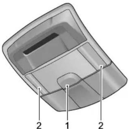
ManualOperation
Presstheswitch(1)toturnthecourtesylighton,press againtoturnoff.Pressoneoftheswitches(2)toturnon amapreadinglight,pressagaintoturnoff.
AutomaticOperation
Courtesylightilluminationoccursautomaticallywhenever thefollowingoccur.
•Thecarisunlocked.
•Adoororthetailgateisopened.
•Thehandsetisremoved,providingthesidelightshave beenilluminatedduringtheprevious30seconds.
Note: If a door or the tail gate is left open for longer than 15 minutes, a 'time-out' function will extinguish the interior lights automatically to prevent the battery from discharging.
If necessary, the automatic illumination features described above can be switched off, as follows:
When the ignition is in positions for press and hold the courtesy light switch (1) for 5 seconds. The interior light will flash and then extinguish. Automatic operation is suspended (manual operation is still available). T orestore automatic operation, repeat the above process.
INSTRUMENTSANDCONTROLS
RearCourtesyLight

Presstheswitch(arrowed)toilluminatethecourtesylight, pressagaintoswitchoff.
INSTRUMENTSANDCONTROLS
PowerSocket
FrontPowerSocket

Pleaseensurethesocketlidisinsertedwhen thepowersocketisnotinuse. Thiswill ensurenodebrisorforeignobjectssenter thesocketpreventingitsuseorcauseshort circuits.
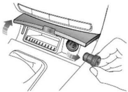
WhentheignitionisinpositionlorII,openthefront ashtraycover,andpulloutthesocketlidtousethepower socket.
Afterusing, insert the socket lid back and closethe front ash tray cover.
Note: The voltage of the powersocket is 12V supply with a maximum power output of 120W.
AccessoryPowerSocket *

Theaccessorypowersocket(A)islocatedintheluggage compartment.Releasethecover(B)toaccessthesocket.
Note: The voltage of the accessory powers octis 12V supply with a maximum power output of 120W.
INSTRUMENTSANDCONTROLS
Note: Extended use of the accessory powersocket when the engine is switched off will cause premature discharging of the vehicle battery.
INSTRUMENTSANDCONTROLS
StorageEquipment
Ashtray

Gentlypresstheashtraycovertoopen.
T oremoveandemptytheashtray,lifttheinserttrayfrom thesurroundandremove.Refitbyinstallingtheinserttray.
Glovebox

T oopentheglovebox, pullthehandle. The integrallamp willilluminateautomatically.
T oclosetheglovebox,raisethelid, and pushtoclose. Ensure the glovebox is fully closed when the car is moving.
INSTRUMENTSANDCONTROLS
CubbyBox

Pressthereleasecatch(arrowed)toopentheliid.Push downtoclose.
INSTRUMENTSANDCONTROLS
CupHolder

Donotplacehotdrinksinthecupholder whilstdriving.Spillagemayresultinpersonal injuryordamage.
FrontCupHolder
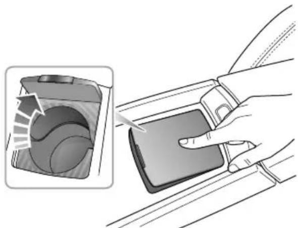
Pulltherearmrestforwardsandlowerintoposition. Raisearmresttoclose.
AirConditioning
60Ventilation
63ElectronicAirConditioning Controls *
67 AutomaticAirConditioning Controls *
AIRCONDITIONING
Ventilation
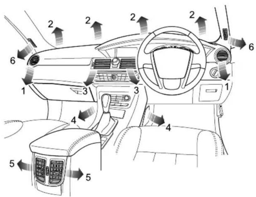
I Sidevents
2Windscreenvents
3Centrevents
4Frontseatfeetvents
5Centreconsolevents
6Frontsidewindowvents
T woadditionalventswhichdirectair tothefeetofrearseatpassengersare fittedbeneaththecarpet.(Notshown inillustration).
AIRCONDITIONING
Theheatingandventilationsystemprovidesfreshorheated airtotheinteriorofthecarfromtheairintakegrillein frontofthewindscreen.
Alwayskeeptheairintakegrilleclearofobstructionssuch asleaves,snoworice.
Particle/PollenFilter
Theparticle/pollenfilterhelpstokeepthecarinteriorfree frompollenanddust. T oremainfullyeffective, thefilter shouldbereplacedattherecommendedserviceinterval.
Vents
CentreVents

Rotatethethumb-wheeldowntocloseoruptoopenthe vents.Directtheairflowbymovingthecontrolinthe centreofthelouvres.
Note: T oincreaseoutputfromthecentrevents, close thesidevents.
AIRCONDITIONING
SideVents

Rotatethethumb-wheeltothelefttocloseortothe righttoopenthevents.Directtheairflowbymovingthe controlinthecentreofthelouvresupordown,orfrom sidetoside.
Note: T oincreaseoutputfromthesidevents, closethe centrevents.
CentreConsoleVents *

Rotatethethumb-wheeldowntocloseoruptoopenthe vents.
Directtheairflowbymovingthecontrolinthecentreof thelouvresupordown,orfromsidetoside.
Note: Centreconsoleventshaveairflowinanyair distribution, butonlycoldairflow.
AIRCONDITIONING
ElectronicAirConditioningControls *
ConsolePanel

I Leftsideheatedseat
2Airconditioningdisplay
3Rightsideheatedseat
4Airdistributionsettingcontrols
5Blowerspeedcontrol
6Heatedrearscreen
7A/Con/off
8Airrecirculation
9Defrost/Demist
10T emperaturecontrol
AIRCONDITIONING
AirConditioningDisplay

IT emperatureselected
2Defrost/Demiston
3Airrecirculationon
4Airdistributionsettingselected
5AirConditioningon
6Heatedrearscreenon
7Blowerspeedselected
TEMP
RotatetheTEMPcontrolclockwisetoincreasethe temperatureinsidethecarorrotateanti-clockwiseto reduce.
Thetemperaturesetwillbeshownbythenumberofbars (between 1 and 8)inthedisplay. Thegreaterthenumber ofbars, thehigherthetemperature.
AirDistribution
Presstheappropriatebuttonontoachievethedesiredair distributionmodes.

For 'face'. Direct sairthroughtheside, centreandcentre consolefacelevelvents.

ForfeetandfaceDirectsaitthefeeventsandthe facevents.

For 'windscreen' and 'feet'. Directsairtothewindscreen and tothefeetvents.
AIRCONDITIONING

For'feet'.Directsairtothefeetvents.
Blower

Rotatetheblowercontrolclockwisetoincreasethe blowerspeedorrotateanti-clockwisetoreducethe blowerspeed.
Theblowerspeedsetwillbeshownbythenumberofbars (between0and8)inthedisplay. Thegreaterthenumber ofbars, thefastertheblowerspeed.
Note:Settheblowerspeedto0whenA/Cisswitched off.
HeatedRearScreen

Theheatingelementsontheinsideoftherear screenareeasilydamaged.DONOTscrape orscratchtheglass.DONOTsticklabels overtheheatingelements.

The heated rearscreen will only function with the engine operating.
Presstöoperate;theLEDintheswitchwillilluminateandasymbolappearsinthedisplay.Theheatedrearscreenwillswitchoffautomaticallyafter12minutes.TheLEDextinguishesandthesymboldisappearswhentheheatedrearscreenisturnedoff.
A/CButton

PresstheA/CButtontoswitchtheairconditioningsystem on.TheA/Csymbolwillappearinthedisplay.Pressagain toswitchchoff.
Note:A/Cwillonlyoperatewhentheengineis running.
Note: The heating function is still available, when the air conditioningsystem is switched off.
AIRCONDITIONING
Whendefrost/demistisselectedpressingtheA/Cbutton willisolatethecompressor,thedefrost/demistselection willremain.
AirRecirculation

With this button pressed, the air inside the car is recirculated and the air intake is closed, preventing the entry of traffic fumes.
When reversing, or operating the front screen washers, the system will automatically switch to interior air recirculation. (If during this process passenger presses the interior/exterior air circulations switch, the airflow will return to the exterior setting).
Thesystemwillcheckeveryminuteifthereversesignalis onandwillautomaticallyrevertbacktotheprevioussetting whenitdetectsthatthedriverhasfinishedreversing.
Note: Leaving the system in recirculation mode can cause the windscreentomist. If this happens, switch
offrecirculationandturnthecontrolstomaximum demisting.
Defrost/Demist

Withthisbuttonpressed,airconditioningisswitchedon, theblowerissettomaximumspeed,airdistributionisset towindscreen,recirculationissettofreshair. Thedefrost symbolwillappearinthedisplaywhenthisisselected.T o switchoffDefrost/demist,pressthebuttonagain.
AIRCONDITIONING
AutomaticAirConditioningControls *
ConsolePanel
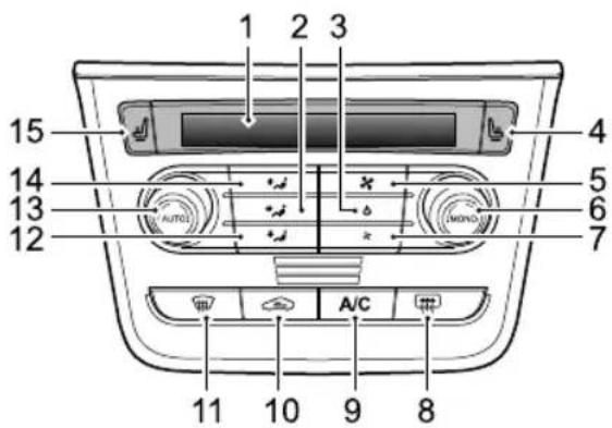
I Airconditioningdisplay
2For'face'
3Systemoff
4Rightsideheatedseat
5Increaseblowerspeed
6MONOcontrol/Rightzonetemperatureselected
7Decreaseblowerspeed
8Heatedrearwindow
9Airconditioningon
10Airrecirculation
I I Defrost/demist
12For'feet'
13AUTOcontrol/Leftzonetemperatureselected
14For'windscreen'
15Leftsideheatedseat
AIRCONDITIONING
AutomaticAirConditioningDisplay

I Leftzonetemperature
2AUTOon
3Airdistribution
4MONOn
5Defrost/demiston
6Rightzonetemperature
7Heatedrearwindowon
8AirConditioningon
9Blowerspeed
10Recirculationon
AUTOControl
AutoControlmodeoperation:
AUTOcontrolisachievedbyrotatingbothtemperature controlstoethesiredemperaturandherpressing theAUTOcontrol.
The conditioning system programme operate below distribution and circulation settingstomaintainoptimumlevelsofcomfortwithinthe caAUTQconwillappea the display put their distribution and belowicowillappeainthe display.
Not AUTNode external temperature is low, higher speed will increase after the engine temperature has risen.
Note: eensure the AUTO controller is efficiently, all windows must be closed and then events must be clean obstruction. Do this field the sunlight sensor, located on top of the fascia.
AIRCONDITIONING
ManualControl
You can set the blower and aird distribution manually, if you prefer. In this condition, AUTO symbol is not shown, indicating that AUTO is not selected.
Note: Youcanswitchtheairdistributionmodebyoperatingthebuttonaccordingtothecurrentmode.
| Currentdistributionmodeindisplay | ||||||
 |  |  |  |  | ||
| Theairdistributionmodeafterpressingbutton | ||||||
| Switch |  |  |  |  |  |  |
 |  | [4ZZX] |  |  |  | |
 |  |  |  |  |  | |
AIRCONDITIONING

For 'face'. Directsairtotheside, centreandcentreconsole vents.

For 'face' and 'feet'. Directsairtothefeetandtotheface vents.

For'feet'.Directsairtothefeetvents.

For'windscreen'and'feet'.Directsairtothewindscreen andfeetvents.

For 'windscreen'. Directsairtothewindscreenvents.
Blower
TheblowerspeedisautomaticallysetwheninAUTO mode.
Inmanualmode, pressthe' + 'buttontoincreaseblower speedorthe' - 'buttontodecrease. Theblowerspeedwill beshowninthedisplay, representedbybetween1and8 bars.
DualZoneT emperatureControl
Operaterightzonetemperatureknoborleftzone temperatureknobtosethecorrespondingside temperatureinthecar .
Ifsettingatemperaturehigherthan28°Corlowerthan 16°C,'HI'or'LO'willappearinthedisplay.
MONOControl

Preshbutton switch between singleton and dualon mode with singleton mode selected the temperatures setting for the carisset by rotating theright
zonetemperatureselected, MONOwillappearinthe display.
PressMONOagaintoswitchtodualzonemodeandthe leftzonetemperatureselectedtosethetemperaturefor thepassengerside.
HeatedRearScreen

Theheatingelementsontheinsideoftherear screenareeasilydamaged.DONOTscrape orscratchtheglass.DONOTsticklabels overtheheatingelements.
Theheatedrearscreenwillonlyfunctionwiththeengine running.Presstöoperate;theLEDintheswitchwill illuminateandasymbolappearsinthedisplay.Theheated rearscreenwillswitchoffautomaticallyafter 12minutes. TheLEDextinguishesandthesymboldisappearswhenthe heatedrearscreenisturnedoff.
A/CButton

PresstheA/CButtontoswitchtheairconditioningsystem on. TheA/Csymbolwillappearinthedisplay.Pressagain toswitchchoff.
Note:A/Cwillonlyoperatewhentheengineis running.
Note: The heating function is still available, when the air conditioningsystem is switched off.
OFF
Presstoswitchtheairconditioningsystem/screenonor off. Whentheairconditioningsystemisswitchedbackon, itreturnstothesettingsinusepriortobeingswitchedoff.
AIRCONDITIONING
AirRecirculation

With this button pressed, the air inside the car is recirculated and the air intake is closed, preventing the entry of traffic fumes.
When reversing, or operating the front screen washers, the system will automatically switch to interior air recirculation. (If during this process passenger presses the interior/exterior air circulations switch, the airflow will return to the exterior setting).
Thesystemwillcheckeveryminuteifthereversesignalis onandwillautomaticallyrevertbacktotheprevioussetting afterfourminutesorwhenitdetectsthatthedriverhas finishedreversing.
During the summer months, in AUTO and fresh mode, the system will monitor the interior temperature. If the outside temperature is high, the system will automatically switch to a circulation mode in order to maximisecabin cooling.
Note: Leaving the system in recirculation mode can cause the windscreentomist.
Defrost/Demist

Pressingthisbuttontheindicatorlightilluminates,the defrost/demistsymbolappearsinthedisplayactivatingthe mostefficientheatersettingtoclearthewindscreenand frontsidewindows.
Pressingthisbuttonagainwillcanceldefrost/demistand restoretheprevioussettings,orpress'AUTO'togo straightintoAutomode.
Note: In AUTO mode and the outside temperature is lower than 5 °C, the heated rearscreen function will operate automatically.
HeatedFrontSeats

Pressingthesebuttonswillactivatethdriver'sand passenger'sheatedseats.
During the 10 minutetimedactivation period these are thermostatically controlled, soon each these are reaches 40° , the heater will turn off. The heat pad will turn on again should its temperature fall to 25° , this will continue until either the switch is operated against turnout them off for the 10 minute operation period expires.
AudioSystem
76AudioSystem
AUDIOSYSTEM
AudioSystem *
Thissectionofthehandbookcoverstheaudiosystems fittedto(S)modelvariants.
Pleasereadtheaudiooperatinginstructionscarefullyin ordertogainmaximumenjoymentfromthesystem.
I Whencleaningthevehicle,ensurethatwaterdoesnot contacttheaudiosystem.
2Useasoftclohtocleanthedisplay.Usealcohol toremovestubborndirt.Donotusewater,solvent orabrasivecleaner,thesesubstanceswilldamagethe display.
3Donotattempttoplaynonstandarddiscs,orany shapewhichisnotround.Donotusedamageddiscs orplaceanyothermaterialintotheCDslot.
4Theaudiosystemisdesignedtooperatebetween temperaturesof-20°Cand+70°C.
5Whentravellingonroughorunevenroads, disc reproductionmaybeimpaired.
6Distortion,interferenceandlackofsignalclarity,are oftenattributedtoafaultintheradio.Problemsof thiskindareusuallycausedbyatmosphericconditions, signalstrength,hillyterrain,tallbuildings,bridgesand evenelectricalinterferencefrompowerlines.
7WhileRDS(RadioDataSystem)automaticretuning easesthisproblem,somemanualretuningmaystillbe needed(especiallyforlocalstations)inareasofweak reception.
8Thebroadcastrangeforgoodqualitystereoreception isnoticeablylessthanitisformono.
IMPORTANT
OnlyusetheCDplayercontrolswhenroadconditions permit.
AudioSystemControlPanel
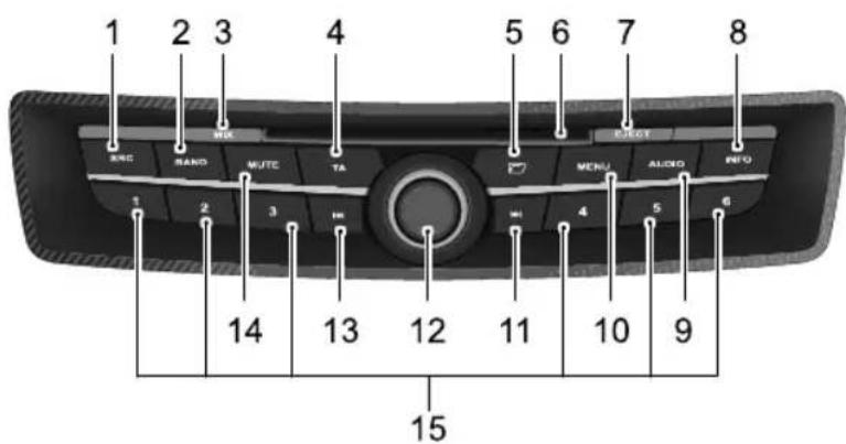
SRC(Source)
BAND
BIX
TAA(T rafficAnnouncement)
Folder
6DSlot
ZDEjecButton
INFO
SoundSettingButton
IMENU
DownwardSearchButton
10n/Off,Volume
UpwardSearchButton
IMUTE
IPreseStationNumberButtons
AUDIOSYSTEM
ControlButtons

Theaudiocontrolbuttonsarelocatedinthecentreofthe faciapanelandhavethefollowingfunctions:
IMFC(Multi-functionController): Used to movethecursorbetweenthemenuoptions. Rotate clockwisetomovethecursordownorright. Rotate anti-clockwisetomovethecursoruporleft.
2Select(SEL)Button:Usetochoosetheoption highlightedbythecursor.
3Bucton:Usetoexitfromcurrentscreenandreturn topreviouslevel.
BasicOperation
On/OffPower
PresstheOn/Offbuttontoswitchontheaudiosystem, pressagaintoswitchoff.
30MinutesPlayFunction
Whentheignitionisswitchedoff, press the On/Offbutton to operate the audiounit for up to 30 minutes. After 30 minutesthe unit will switch off. T o switch on again, press the on/off button.
SelectMode
PressSRCbuttontochangetesourceoftheoutput. The audiounitwillcyclethroughthefollowingoptions,radio, CDplay(ifthereisadiscintheCDplayer),USB(ifUSBis connected),andAUX.
Note: CDplaycanonlybeselectedwhenthereisa discintheCDplayer.
Note: USBcanonlybeselectedwhenaUSBsourceis connected.
VolumeControl
Rotatethevolumecontrolclockwisetoincreasethe volumeoranti-clockwisetodecreasevolume.
SoundSettings
PresstheSoundSettingsbuttontoadjustthesoundto suityourlisteningrequirements.Firstpressofthebutton selectsBass.RotatetheOn/Offvolumecontroltoachieve thesettingyourequire,thenpressthesoundbuttonagain toselect,inturn,theT reble,FaderandBalancesettings.
Thedisplaywillreverttoitspreviousmode5secondsafter thelastbuttonpress.
MUTE
Presstomutethesoundfromtheaudiosystem.Press againtoresumeaudiosound.
IfinCD/USBplay, theMUTEbuttonpausesCD/USBplay.
TA(T rafficAnnouncement)
PresstoenableTAfunction,iftheradioison,theplayer willsearchautomatically,ifcurrentstationdoesn'tsupport TA,pressthebuttonagaintodisableT A.
WhenaTAisreceivedduringCD/USB playback, theMIX function(ifselected) is cancelled.
SelectFolder
WhenaMP3/USBisplaying, pressthefolderbutton and rotatetheMFCtoselectthefolder, pressthebutton again, thefirstmusictrackoftheselectedfolderwillplay automatically.
SettingDateandTime, AutoVolume, RDS (RadioDataSystem)
PressMENUtoselectsettingdateandtime,autovolume andRDS.
RotatetheMFCtoselectthedateandtime,autovolume andRDSoptions.PresstheMENUbuttonagainandrotate theknobtoset.
AUDIOSYSTEM
RadioOperation
SelectSource
PresstheSRCbuttontoselectradioasthesource.
BAND
RepeatedlypresstheBANDbuttontoselectFM1,FM2, FMAST,MWorLWfrequencies.
RadioT uning
Thereare3tuningmodes:
- Searchtuning
•Manualtuning
•Pre-settuning
SearchT uningMode
Brieflypresstheupordownsearchbutton. Theradio automaticallysearchesthefrequencyrange(eitherupon downdependinguponwhichofthebuttonsispressed) lookingforaradiostationofacceptablestrength.Once astationisfound,thatstationwillbeplayed.
ManualT uningMode
Pressandholdeitherofthesearchbuttonsuntilthe 'MANUAL'isdisplayonthescreen.Presseitherofthe searchbuttonstoenterintomanualtuningmode.5 secondsafterthelastbuttonpress,thesystemwillleave manualtuningmode.
Pre-setT uningMode
Upto30radiostationscanbestored(FMI,FM2,FMAST, MW, LW).Pressnumbers1-6toselectastoredfrequency.
StoreStation
Therearemanualstoreandautostoremodes.
ManualStore
- Pressthe'BAND'buttonandselectthedesired waveband.
- Usesearch,manualorpre-settuningmodestoturnto thedesiredstation.
- Pressany'Number'buttonformorethan2seconds. Thefrequencieswillbeautomaticallystored.
Note: Manualstoreoverwritesanystationsalready storedonthepre-setbuttons.
AutoStore
- Press'BAND'buttontoselectFMfrequency.
- Pressandholdthe'BAND'button.Auto-storescans thewavebandtofindthesixstrongestfrequenciesand thenstoresthemontheFMASTpre-setbuttonsin orderofsignalstrength.
Ifauto-storeisunabletofindsixstrongstations,the remainingpre-setsarenotused.
Note: Auto-storeoverwritesanystationsalready storeontheASTpre-setbuttons.
RDS(RadioDataSystem)Settings
PressMENUtosetAF(AlternativeFrequency)on/off,CT (Clock,TimeandDate)on/off,REG(Region)on/off,EON (EnhancedOtherNetworksettings,T AVOL(TAVolume) settings,androtatetheknobtoachievethesettingyou require.
When the RDSradioisplaying, and then a name of the station radioexists, it is shown on the display.
RepeatedlypresstheINFObuttonpreRTY (ProgrammeType),EXTofthecurrentRDSradio station.
Note: AFshowsthattheRDSistuningtothestrongest signalforthestationyouhaveselected.Itreturnstoa differentfrequencywhenyoumoveintoanotherarea.
Note: CTfunctiondoesnotalwaysworkinsomeEU countries.
Note: INFObuttonhasnofunctioninAMorinAUX.
NGEnchronisationRDSN automaticallydeactivatediftheusermakesmanual changestotheclockordate.
Note: ChangestoREGsetting from "ON" to "OFF" are storeonly in Presets.
AUDIOSYSTEM
CD,USB,AUXPlayer

TheCompactDisc(CD)playerfittedtoyour carwillonlyacceptonediscatatime.
TheCD/USBcompatibilityinformationasfollows:
| CD-R/RWUSB | ||
| FileSystem | ISO9660WithJoliet (UDFnotsupported) | FAT |
| MaxNo.ofFolders512 | Folders+ Files<=999 | |
| MaxNo.ofFiles | 511 | |
| MaxFolderNested Depth | 8 | |
| PlayableFileTypes | CD-A,MP3,WMAMP3/WMA | |
LoadingaCD
Makesurethatthediscispositionedwiththelabel sideupwards,thengentlypushitintotheslotuntilthe mechanismdrawsthediscinfully.CDplaywillstart immediately.
ConnectUSB
InsertaUSBmemorystickviatheUSBconnection insidethestowagetraylocatedonthelowersideofthe instrumentpaneladjacenttothedriver'sdoor ,pressSRC toaccesstheUSBmode.
ConnectAUX
InsertanAUXdeviceviatheAUXconnectioninsidethe stowagetraylocatedonthelowersideoftheinstrument paneladjacenttothedriver'sdoor,pressSRCtoaccessthe AUXmode.

T rackSearch
I Press the UpwardSearch Button on cetoipto the beginning of then next track.
2Ifthetrackelapsedtimeismorethan2seconds,press theDownwardSearchButtononcetoreturntothe startofthecurrenttrackandpressagaintostartthe previoustrack.Ifelapsedtimeislessthan2seconds,
presstheDownwardSearchButtononcetoreturnto theprevioustrack.
FastForward/Rewind
I PressandholdtheDownwardsSearchButtontofast rewind.
2PressandholdtheUpwardsSearchButtontofast forward.
MIX
PressMIXtoplaythetracksonaspecificCD/USBina randomorder.Pressagaintocancelthefunction.
AUDIOSYSTEM
INFO
WhenplayingMP3/WMAfiles,repeatedlypressINFOto viewfilename,foldernameandanyotheridentificationthat hasbeenaddedtothedisc.Ifthenumberofcharacterswill notfitonthedisplay,thetextwillbescrolledacrossthe display.
EjectingCD
Presstheejectbutton. Thediscwillbeejectedfromthe playerandcanthenberemoved.
RemoveUSB
DonotremoveUSBdirectlywhenitisplaying,itwill damagetheUSBfiles.
Antenna

Theantennaislocatedattherearoftheroof.Avoid bendingtheantenna.Howeverwhenrequired,e.g.when usinganautomaticcarwashingfacility,pleaseensurethat theantennaisremoved.
T oremovetheantennaunscrewtheantennaanti clockwise.
SeatsandRestraints
86Seats
92SeatBelts
96 AirbagSupplementaryRestraint System
103ChildRestraints
SEATSANDRESTRAINTS
Seats
CorrectSeatingPosition

Toavoidtheriskoflossofcontroland personalinjury, DONOTadjusttheseats whilethecarismoving.

T akecarewhenadjustingtheheightofthe driver'sseat—thefeetoftherearpassenger couldbecometrappedwhentheseatis lowered.

DONOTallowfrontseatoccupantsto travelwiththeseatbacksreclinedsteeply rearwards. Optimumbenefitisobtained fromtheseatbeltwiththebackrestangle settoapproximately25°fromtheupright (vertical).
The driver and front passenger seat should be positioned as far rearward as practical. A properly adjusted seat helps reduce risk of injury from sitting to a closeto an inflating airbag.
Makesureyourdrivingpositioniscomfortableandenables youtomaintainfullcontrolofthevehicle.
SEATSANDRESTRAINTS
HeadRestraints

Adjusttheheadrestraintsothatthetopof theheadrestraintisinlinewiththetopof theoccupant'sheadandthebackofthe occupant'sheadisascloseaspossibletothe headrestraint.

Undernocircumstancesarethehead restraintstobeusedforhanginganything.
Headrestraintsaredesignedtopreventrearward movementoftheheadintheeventofacollisionor heavybraking,therebyreducingtheriskofheadandneck injuries.
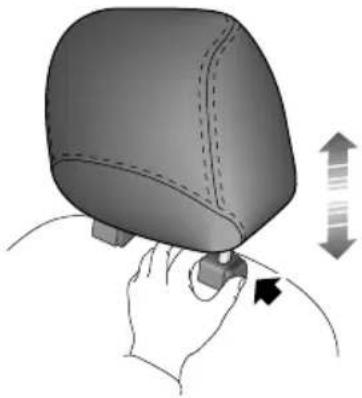
Pressthebutton(arrowed)andpushtheheadrestraint downwardstoloweritsposition,orlifttheheadrestraint toraiseitsposition.Theheadrestraintcanberemovedby liftingfullyupwards.
SEATSANDRESTRAINTS
ManualFrontSeat

I Forward/Rearward Adjustment
Liftthelever(I)andslidetheseatintoposition.Make suretheseatislockedinpositionbeforedriving.
2HeightAdjustment
Pullthelever(2)upwardswithapumpingactionto
raisetheseatasrequired.Pressdownonthelever
withapumpingactiontolowertheseat.
3BackrestAdjustment
Liftthelever(3)andallowtheseattomove,tiltthe backresttothedesiredposition.
4LumbarSupportAdjustment
Rotatethehandwheel(4)toadjust.
SEATSANDRESTRAINTS

I Forward/Rearward Adjustment
Pushandholdtheswitch(1)forwardsorrearwardsto movetheseat.
2SeatCushionHeight
Pushtheswitch(2)upordowntoraiseorlowerthe cushion.
3BackrestAdjustment
T wisttheswitch(3)forwardorbackwardsuntilthe desiredangleisachieved.
4LumbarSupportAdjustment
Rotatethehandwheel(4)toadjust.
HeatingFrontSeat

Pressingthesebuttonswillactivatethe driver'sandpassenger'sheatedseats.
During the 10minutetimedactivationperiodtheseare thermostaticallycontrolled,sooncetheseatreaches40°, theheaterwillturnoff.Theheatpadwillturnonagain shoulditstemperaturefallto25°,thiswillcontinueuntil eithertheswitchisoperatedagaintoturnthemofforthe 10minuteoperationperiodexpires.
Note: Pleasereferto 'AirConditioning' for the location of the two buttons.
SEATSANDRESTRAINTS
IMPORTANT
- Donotcovertheheatedseatswithblankets, cushionsorotherinsulationtypeobjectors materials.
• If theseatisheated upto 45°C and continues getting hotter when using seat heating system, please turn off seat heating and contact MGA authorised Repairer.
•Overuseofthedriver'sheatedseatmaycause drowsinessandcouldthereforeaffectsafety.
FoldingtheRearSeats

DONOTcarryobjectsontherearparcel shelf-theycouldbecomedangerous projectilesintheeventofanaccident.

To increase luggagespace, fully lower all head restraints, presse either a therelease catech and fold these at backrest forward.
SEATSANDRESTRAINTS
RearSeatBackrests'LatchSecure'Indicators
When returning these at to the upright position, ensure that the catches are engaged and that the red strip is not visible - this confirm that the back rest is secure.
Note: When returning these at to the upright position, ensure that these at belts are not trapped.
SEATSANDRESTRAINTS
SeatBelts
SafetyInformation

Theairbagsupplementaryrestraintsystem (SRS)isdesignedtoaddtotheoverall effectivenessoftheseatbelts.Itdoesnot replacethem.SEATBEL TSMUSTALWAYS BEWORN!

Ensure that all seat belts are worn correctly -anim properly worn seat belt increase the risk of death or serious injury in the event of a collision.
Theseatbeltsfittedtoyourvehicleareintendedforuseby adultsizedpersons.Eachbeltisintendedforoneperson only.
IMPORTANT
- DOmakesureallpassengersaresecurelystrapped inatalltimes-evenfortheshortestjourneys.
- ALWA YSadjustseatbeltstoeliminateanyslackin thewebbing.T obefullyeffective,theseatbeltmust remaininfullcontactwiththebodyatalltimes.
•ALWA YSfitthelapstrapaslowonthehipsas possible(neveracrosstheabdomen),andensure thatthediagonalbeltpassesacrosstheshoulder withoutslippingofforpressingontheneck.
• DONOTwearseatbeltsoverhard,sharporfragile itemsinclothing,suchaspens,keys,spectaclesetc.
•Alwaysreplaceatbeltassemblythathas withstoodthestrainofaseverevehicleimpact,orif thewebbingshowssignsoffraying. - Wherepossibleusetheseatbeltstosecurelarge itemsofluggagethataretobecarriedontheseats-intheeventofanaccident,unsecureditemsbecome flyingmissilescapableofcausingseriousinjury.
IMPORTANT
- DONOTuseaseatbeltthatistwistedor obstructedinanywaythatcouldimpedeitssmooth operation.
- DONOTallowfrontseatoccupantstotravelwith theseatbacksreclinedsteeplyrearwards.Optimum benefitsobtainedfromtheseatbeltwiththeseat backanglesettoapproximately 25° fromtheupright (vertical)position.
• DONOTallowforeignmatter(particularly sugary food and drink particles) to enter these seat belt locks - such substances can render the locksin operative.
•Inmostcountries, allooccupantsarerequired by law to wear a seat belt, unless they have been issued with amedicalexemption certificate. - During pregnancy, women should wear the lapbelt across the hips below the baby.
FasteningtheBelt

Donotattachanyadditionaldevicetothe seatbeltinanywaywhichmayimpedeits operation.

Pulltheseatbeltsteadilyovertheshoulderandacrossthe chestand,ensuringthewebbingisnottwisted,insertthe metaltongueplateintothebucklenearestthewearer.A 'click'indicatesthatthebeltissecurelylocked.
Note: If when using there are centre 3 point seat belt you encounter difficulty fastening it, releasethe belt, allow it to retract then pull out slowly, then lock it securely into place.
SEATSANDRESTRAINTS
ReleasingtheBelt
Presstheredbuttonontheseatbeltbuckletoreleasethe belt.
UpperAnchorageHeightAdjustment

Pressthehandleandraiseorlowertheseatbeltupper anchoragesothattheseatbeltisinacomfortableposition.
CheckingSeatBelts
- Withtheseatbeltfastened,givethewebbingnearest thebuckleaquickpull-thebuckleshouldremain securelylocked.
- Unreelthewebbingtothelimitofitstravel.Checkthat webbingisfreefromsnagsandcutsandfurthercheck forvisualsignsofwearorfraying.Allowthewebbingto retract,checkingthatretractionissmooth,continuous andcomplete.
- Withthewebbinghalfunreeled, holdthetongueplate andgiveitaquickforwardpull-themechanismmust lockautomaticallyandpreventanyfurtherunreeling. Ifaseatbeltshouldfailanyofthesetests,contactyour MGAuthorisedrepairerforinspectionattheearliest opportunity.
SEATSANDRESTRAINTS
ReplacingSeatBelts

Alwaysreplaceatbeltassemblywherethe webbingshowssignsoffraying.
Regularlyinspectthebeltwebbingforsignsoffraying,cuts andwear;alsopayparticularattentiontotheconditionof thefixingpointsandadjusters.
SeatBeltPre-tensioners *

Theseatbeltpre-tensionerswillonly beactivatedonceandthenMUST BEREPLACED.Failuretoreplace the pre-tensionerswillreducetheefficiency of thecar'sfrontrestraintsystems.
Theseatbeltpre-tensionersactivateinconjunctionwith theairbagtoprovideadditionalprotectionintheeventof aseverefrontalimpact. Thepre-tensionersautomatically retracttheseatbelts. Thisreducestheforwardmovement ofthebeltwearerintheeventofaseverecollision.
Note: Theseatbeltpre-tensionerswillNOTbe activatedbyminorimpacts.
Theseatbeltpre-tensionersarelocatedinsidethefront seatbeltreels.
The airbag warning light on the instrument panel will alert the driverto anymalfunction of these at belt pretensioners (see 'Airbag Warning Light and Messages').
If the pre-tensioners have been activated, these at belts will still function as restraints, and must beworn in the event that the vehicler remains in a drivable condition.
IMPORTANT
Theremovalorreplacementofapre-tensionermust bearried by the manufacture trained dealer technicians.
Year of the tidal registration (installation that replacements a belt pre-tensioner), some components will need to be replaced The appropriate page of the Warranty and Maintenance Manual must be signed and stamped on eachework has been completed.
SEATSANDRESTRAINTS
AirbagSupplementaryRestraint System
Airbags

TheairbagSRSprovidesADDITIONAL protectioninasevereimpactonly.ltdoes notreplacetheneedtowearaseatbelt.
The SRS system incorporates front and side air bags and side head impact protection air bags for both the driver and front seat passenger.
Thefrontairbagsarelocatedinthecentrepadofthe steeringwheelandinthefasciapanelabovetheglovebox.
Sideairbagsarepositionedinthebackrestpaddingonthe outwardsideofbothfrontseats.
Sideheadimpactprotectionairbagsaresituatedbehindthe headliningabovethedoors.

Note: The frontairbags are not designed to operate as a result of rear collision, minor frontal or side impacts, or if the vehicle overturns; nor will it operate as a result of heavy braking.
Note: Inflation and deflation of the front and side air bag stakes place every quickly and will not protect against the effect of secondary impact that may occur.
Provided the front seat occupants are correctly seated and with seat belts properly worn, the air bags will provide additional protection to the chest and facial areas in the event of the car receiving a severe frontal impact. Side air bags and side head impact protection air bags are designed to offer additional protection to the sides of the body facing the impact, if a severeside collision occurs.
IMPORTANT
•Evenifthevehicleisequippedwithairbags,you shouldalwayswearseatbeltstoreducetheriskof severecasualtyintheeventofacollision.Wearing seatbeltshelpsreducethepossibilityofhittingor beingpushedawayfrom,anyobjectintheinterior ofthecar.Theairbagsaresupplementaryprotection toseatbelts.Theyareanaidto,NOTreplacement of,seatbelts.
•The airbagstogether with the 3-point seat belts provide optimum protection for adults, but not for children. Children should be protected by child restraints.
AirbagDeployment

Tominimisetheriskofaccidentalinjury frominflatingairbags,seatbeltsshouldbe worncorrectlyatalltimes.Inaddition,both driverandfrontseatpassengershouldadjust theirseattoprovidesufficientdistancefrom thefrontairbagssideairbags/sidehead impactprotectionairbagsarefitted,both driverandfrontseatpassengershouldbe seatedtomaintainsufficientdistancefrom theupperpartofthebodytothesides ofthevehiclehiswillensuremaximum protectionwhenthesideairbags/sidehead impactprotectionairbagsaredeployed.
Intheeventofacollision, theairbagcontrolunitmonitors therateofdecelerationoraccelerationinducedbythe collision,todeterminewhethertheairbagsshouldbe deployed.
Operationoftheairbagisnotdependentonthespeed ofthecar,butonthetypeandsizeofobjecthit,angle ofimpactandtherateatwhichthecarchangesspeedas
SEATSANDRESTRAINTS
aresultofacollision.Deploymentoftheairbagisnot dependantontheamountofdamagetothevehicle.
Inthecaseofaseverefrontalcollision,bothfrontairbags willbedeployed.Inthecaseofaseveresidecollision,only thesideairbagandsideheadimpactprotectionairbagon theimpactsideofthevehiclewillinflate.
However,theremayalsobeimpactconditionswhereby onesetofsideandbothfrontairbagsdeployatthesame time,orwherefrontandsideairbagsrespondseparately asaresultofasecondaryimpactoccurringaftertheinitial collisionhastakenplace.
Airbaginflationisvirtuallyinstantaneousandoccurswith considerableforce,accompaniedbyaloudnoise. The inflatedbag,togetherwiththeseatbeltrestraintsystem, limitthemovementofafrontseatoccupant,thereby reducingtheriskofinjurytotheheadanduppertorso.

Note: When an airbaginflates, afinepowderis released. This is not an indication of a malfunction, however, the powder may cause irritation to the skin and should be thoroughly flushed from the eyes and any cuts or abrasions of the skin. After inflation, front and side air bags deflate immediately. This provides a gradual cushioning effect for the occupant and also ensures that driver's forward vision is obscured.
IMPORTANT
- Obstructionsbetweenanairbagandtheoccupant mayaffectthecorrectdeploymentoftheairbag. Obstructionsmustnotinterferewiththeairbag inflationpassages.Accessoriesmustnotbeattached toorobscureanairbag.
- Frontseatpassengersshouldnotplacefeet,knees oranyotherpartofthebodyincontactwith,orin closeproximityto,afrontairbag.
• Aninflatingairbagcancausefacialabrasions and otherinjuriesiftheoccupantistooclosetothe airbagatthetimeofitsdeployment.
FrontSeatSideAirbags

Ensuresufficientdistanceexistsbetween thedriverandfrontpassengers'torsosand thesideofthevehicletoensurecorrect deploymentofthefrontsideairbags.
Frontseatsideairbagsaredesignedtoprotecttheheadand chestandwillbedeployedintheeventofthecarreceiving aseveresideimpact.Itwillnotbedeployedintheevent ofafrontorrearimpact.
Intheeventofasevereimpactononesideofthevehicle, theseatsideairbagwillbedeployedfromthesideofthe seat,onthatsideofthevehicle,topprovideacushionofair toprotectthefrontseatoccupant. Theseatsideairbagon theothersideofthevehiclewillnotbedeployed.
Seatswithsideairbagscanbeidentifiedbyan 'Airbag' markingonthesideoftheseatbackrest.
Note: Them manufacture and material of theseatis important to ensure correct operation of theseat side air bag. Donot fit seat covers unless they are
SEATSANDRESTRAINTS
approvedbythemanufacturer.ContactyourMG AuthorisedRepairertorepairorreplacefrontseats.
SideHeadImpactProtectionAirbags

Ensuresufficientdistanceexistsbetween thedriverandfrontpassengers'torsos andthesideofthevehicletoensure correctdeploymentofthesideheadimpact protectionairbags.
Sideheadimpactprotectionairbagsaredesignedtoprotect theheadandneckandwillbedeployedintheeventofthe carreceivingaseveresideimpact.Itwillnotbedeployed intheeventofafrontorrrearimpact.
Intheeventofasevereimpactononesideofthevehicle, thesideheadimpactprotectionairbagswillbedeployed fromtheroof,onthatsideofthevehicle,topprovidea cushionofairtoprotectthefrontseatoccupant.Theside headimpactprotectionairbagsontheothersideofthe vehiclewillnotbedeployed.
AirbagWarningLightandMessages

DONOTservice,repair,replace,modifyor tamperwithanypartoftheairbag,orwiring inthevicinityofanairbagcomponent;this couldcausethesystemtoactivate,resulting inpersonalinjury.
Awarninglight, mountedontheinstrumentpack, will alertyoutoanymalfunctionoftheairbags. Thelightwill illuminateasasystemcheckwhentheignitionisswitched onandwillextinguishafterapproximatelyfourseconds.
Ifanyofthefollowingsymptomsoccur,thesystemshould beinspectedbyyourMGAuthorisedRepairer.
The warning light fail to illuminate when the ignition is on.
Twarnlightsinguivithin approximatelyfoursecondsaftertheignitionis switchedon.
Thewarninglightilluminateswhilethecarisbeing driven.
ServiceInformation

DONOTinstallormodifytheairbag.Any changestothevehiclestructureorairbag systemwiringharnessarestrictlyprohibited.
AlwayscontactyourMGAuthorisedRepairerif:
•anairbaginflates.
• thefrontorsideofthevehicleisdamaged(evenifthe correspondingairbaghasnotinflated).
•anypartofanairbagmodulecoversshowsignsof deteriorationordamage.
ThecomponentsoftheSRSSystemaresensitiveto electricalandphysicalinterference;itisrecommended thatyouALWA YSseekMGAuthorisedRepairerbefore carryingoutanyofthefollowing:
-Removalorrepairofanywiringorcomponentinthe vicinityoftheSRSSystem,including:thesteeringwheel,steeringcolumn,frontseats,fasciaandinstrument panel.
• Installationofelectronicequipmentsuchasamobile phone,two-wayradioorin-carentertainmentsystem.
- Attachmentofaccessoriesto,ormodificationof,the frontorsideofthevehicle.
- Removal, replacement, or retrimming of a front seat cover.
IMPORTANT
•Theremovalorreplacementofanairbagmodule mustbecarriedoutbyanMGAuthorisedRepairer.
•After 10 years from the initial date of registration (or installation date of replacement air bag), some components will need to be replaced by an MG Authorised Repairer. The appropriate page of the Warranty and Maintenance Manual must be designed and stamped on each homework has been completed.
SEATSANDRESTRAINTS
DisablingthePassengerAirbag

The Passenger Airbag should only be disabled when are ar facing child seat is fitted to the front passenger seat.

Whenanadultisseatedinthefront passengerseat,ensurethattheairbagis switchedon.

Theairbagdisableswitchislocatedontheendofthe dashboard.T odisablethepassengerairbag,insertthe emergencykeybladecontainedwithinthehandset.T o removetheemergencykeyfromthehandsetrefertothe StartingandDrivingEmergencyUnlockingsectionofthe ownershandbook.
DisposingoftheVehicle
Uninflatedairbagsarepotentiallyverydangerousandmust besafelydeployedinacontrolledenvironmentbyqualified personnel,beforevehicleisscrapped.
ChildRestraints

Childrenmustbesecuredinthevehicleina childrestraintsystemappropriateforweight andsize.

DONOTputthechildonthelaporinarms whensittinginanyseat.


TheISOFIXanchoragesintherearseatare designedforusewithISOFIXsystemsonly.

Wheninstallingandusinganychildrestraint system,alwaysfollowthemanufacturer's instructions.

Failuretofollowtheadvicecouldresultin serious injuryorevendeathofthechild.

ChildRestraintInstructions
It is recommended that children below the age of 12 years old should be seated on there are seat of the vehicle, in a child restraints system appropriateto the children's weight and size.
It is recommended that a child restraintsystem that complies with UNECER44 standard are fitted in this vehicle. Checkmarkings on the child restraints system.
Infantslessthan2yearsoldshouldberestrainedinaninfant childrestraintsystem.
Thereareanumberofchildrestraintsystemsavailableof differenttypeandspecification.Foroptimumprotection,
SEATSANDRESTRAINTS
itisrecommendedthatyouchooserestraintsystems appropriatetothechild'sageandweight.
It is important to comply with installation instructions supplied by the child restraint manufacturer and that child restraints system is properly secured to the vehicle. Failure to follow these instructions may cause death or serious injury to the child in an event of sudden stop or accident.
Note: Use an appropriate child restraint system until the child becomes large enough to be properly restrained by the vehicle's seat belts.
Note: DONOTinstallarearfacingchildrestraint systeminthefrontpassengerseat, unlessthefront passengerairbaghasbeendeactivatedorwhenan airbagmanualdeactivationswitchisnotfittedtothe vehicle.
Note: Frontpassengerseatmustbepositionedfully rearwardsforinstallationofrearfacingchildrestraint systems.
No need facing the strain system installations in there are seat may require forward adjustment of the front seat.
Note: Seatheadrestraintsmayneedtobeadjustedor removedforinstallationofsomeforwardfacingchild restraintsystems.
Note: Rearparcelshelfmayneedtobetemporarily detachedoenableTopetheraccesstatheanchorage intherearoftheseatback.
IMPORTANT
- It is recommended that childrestraints system that complies with UNECER44 standard are fitted in this vehicle. Checkmarkings on the child restraint system.
- It is recommended that children should always be seated in therear of the vehicle in a child restraint system. If it is necessary for a child to travel in the front, it is essential that these are fully rearwards, these at backup right and the child dissecured in FORWARD FACING children restraint system.
- Rememberthatintheeventofacollisionorheavy brakingachildrestraintsystemthatisnotcorrectly fittedcouldmoveandinjureotheroccupants.Make surethatachildrestraintsystemisproperlysecured evenifnochildiscurrentlyusingit.
SEATSANDRESTRAINTS
ApprovedChildRestraintPositions(forNon-ISOFIXChildRestraints)

If vehicle is not equipped with passenger air bag disables switch, rearward facing child restraints MUST NOT be installed on the front passenger seat.
ApprovedChildRestraintPositions(forNon-ISOFIXChildRestraints)
| WeightGroup | SeatingPositions | ||||
| FrontPassenger | RearOutboardRearCentre | ||||
| Without Passenger AirbagDisable Switch | WithPassenger AirbagDisable Switch | ||||
| Airbag ON | Airbag OFF | ||||
| 0(upto10kg) | XXUUX | ||||
| 0+(upto13kg) | XXUUX | ||||
| I(9to18kg) | XXUUX | ||||
| II(15to25kg) | UUUUX | ||||
| III(22to36kg) | UUUUX | ||||
| U=Suitablefor‘Universal’categoryrestraintsapprovedforuseinthismassgroup.X=Seatpositionnotsuitableforchildreninthismassgroup. | |||||
ApprovedChildRestraintPositions(forISOFIXChildRestraints)
| WeightGroupSizeClass | Fixture | ISOFIXPositions | |
| RearOutboard | |||
| Carrycot | F | ISO/L1 | X |
| GISO/L2 | X | ||
| 0(upto 10kg) | E | ISO/RI | IUF |
| 0+(upto 13kg) | E | ISO/RI | IUF ,IL |
| D | ISO/R2 | IUF | |
| CISO/R3 | IUF | ||
| I(9to 18kg) | D | ISO/R2 | IUF |
| CISO/R3 | IUF | ||
| B | ISO/F2 | IUF | |
| BI | ISO/F2X | IUF ,IL | |
| AISO/F3 | IUF | ||
| II(15to25kg)N/AN/A | X |
SEATSANDRESTRAINTS
| WeightGroupSizeClass | Fixture | ISOFIXPositions | |
| RearOutboard | |||
| III(22to36kg)N/AN/A | X | ||
| IUF=SuitableforISOFIXforward-facingchildrestraintsystemsofuniversalcategoryapprovedforuseinthismass group.IL=SuitableforparticularISOFIXchildrestraintsystems(CRS)givenintheattachedlist.TheseISOFIXCRSare thoseofthe'specificvehicle','restricted'or'semi-universal'categories.X=NoISOFIXchildrestraintsystemapprovedinthisweightclass.ISOFIXsizeclassandseatdeviceA-ISO/F3=Forward-facingchildrestraintsystemB-ISO/F2=Forward-facingchildrestraintsystemBI-ISO/F2X=Forward-facingchildrestraintsystemC-ISO/R3=Rear-facingchildrestraintsystemD-ISO/R2=Rear-facingchildrestraintsystemE-ISO/RI=Rear-facingchildrestraintsystemF-ISO/LI=LeftLateralFacingpositionCRS(carry-cot).G-ISO/LI=RightLateralFacingpositionCRS(carry-cot).Note:ForChildRestraintsofClassR,thefrontseatmayrequireforwardadjustmentforsomerearwardfacing childseatinstallation. | |||
SEATSANDRESTRAINTS
ListofApprovedChildRestraintsSystems
| WeightGroupSize | classCRSname | FixtureType | Category | ||
| 0+(upto13kg) | E | BritaxBabySafePluswith supportseatframe | ISO/RI | RearFacing | Semi-universal |
| I(9to18kg) | BI | BritaxDuoPluswith T opT ether | ISO/F2X | ForwardFacingUniversal |
ISOFIXChildRestraintSystemsFastenvehicle-approvedISOFIXchildrestraintsystemsto
themountingbrackets.

When using ISOFIX mounting brackets for seat mounting, universally approved child restraints systems for ISOFIX may be used.
T op-tetherChildRestraintSystems

Childrestraintanchoragesaredesigned withstandnlyhosloadimposedy correctfittedhildestrainundero circumstancesaretheytobeusedforadult seatbeltharnessesorfoattachingother itemsorequipmenttothevehicle.
SEATSANDRESTRAINTS

- FastentheT op-tetherofthechildrestraintsystem totheanchorattherearoftherearpassengerseat backrest.
Note: When using seat mounting, universally approved childrestraintsystems, Top-tethermustbeused.
Note: Pleaserefertothechildrestraintsystem manufacturer'sinstructionsfordetails.
StartingandDriving
112Handsets
116 Child-ProofLocks
117AlarmSystem
122 StartingandDriving
I 26EconomicalandEnvironmentalDriving
130 DieselParticulateFilter
132FuelSystem
1366-SpeedManualTransmission
137 BrakeSystem
144StabilityControlSystemandTraction ControlSystem
146 TyrePressureMonitoringSystem (TPMS)
148 CruiseControl *
150IntelligentStop/StartSystem
153 ParkingAidSystem
155LoadCarrying
STARTINGANDDRIVING
Handsets
Introduction

Pleasekeepthesparehandsetinasafeplace -notinthecar!

It is recommended that spare handsets are not kept on the same key ring, sincethism may cause interference and prevent correct key recognition and therefore prevent the engine from starting.

Theremotehandsetscontainsdelicate electroniccomponentsandmustbe protectedfromimpactandwaterdamage, hightemperatureandhumidity,direct sunlightandtheeffectsofsolvents,waxes andabrasivecleaners.
Y ouaresuppliedwithtworemotehandsetswithintegral emergencykeyswhichoperatealllocks.
Thehandsetssuppliedwithyourcarareprogrammed yourecuritystlandsettsdteen programmedaccordingtoyourcar ,itcannotstartthe engine.
Theremotehandsetsonlyworkwithinacertainrange. Itsworkscopeissometimesinfluencedbythehandset batterycondition,physicalandgeographicalfactorfor safetyconsideration,afteryoulockyourcarbytheremote handset,pleaserecheckifthecarislocked.

Tl ailgatereleasebutton
Lockbutton
3nlockbutton
STARTINGANDDRIVING
If your handset is lost/stolenor broken, are replacement can be obtained only from MGA authorised Repairer. The lost/stolen handset can be deactivated. If the lost handset is found, MGA authorised Repairers can reactivate it.
Note: Replacementhandsets are only available via MGA authorisedRepairer.
Note: Thenewhandsetcannotbeofferedtoyou immediatelybecauseitneedssometimetomatch thenewhandsetwiththevehiclebyMGAuthorised Repairer.
HandsetBatteryRemovingandRefitting
If the battery needs replacing, the message centrewill display 'KeyBatteryLow' whenever the handset is operated. Themessagewill berepeatedly displayed for severalsecends when the ignition is switched off.

I Slidethetopofthehandset(A)forwarduntil releases(I).
2Removetheplasticbungfromthehandset(2).
IMPORTANT
Takegreatcarewhenremovingtheplasticbungto ensurethattheemergencykeydoesnotfallout.
STARTINGANDDRIVING
3Notethelocationofcircuitboard, removethecircuit board(4)fromthehandset.
4Useascrewdrivertoprisethebattery(3)fromits mounting, takingcaretoavoidtouchingthecircuit boardorthemetalbatterycontacts.
Note: Fingermarkswilladverselyaffectbattery life; if possible, avoidtouchingtheflatsurfacesof thebattery.
5Fitthenewbattery, ensuring that correct polarity is maintained ('+'sidefacingup).
Note: It is recommended that you fit a CR2032 replacement battery.
6Insertthecircuitboardintothehandsetandrefitthe plasticbung.
7Fixthetopofthehandset,thenslideitbackwards.
8Insertthehandsetintoignitionswitchto resynchroniseit.
IMPORTANT
Use appropriate battery damage handset. Thenew replacement'sratedvoltage, sizes and specifications must be the same with the old one.
Inappropriatefittingofthebatterymaydamagethe key.
Disposefnesedbatterynusstrictlin accordancewithrelevantenvironmentalprotection acts.
STARTINGANDDRIVING
EmergencyKey

Ifforanyreason,thehandsetcannotunlockorlockthe car,youcanunlockorlockitbyinsertingtheemergency keyinthedriver'sdoorlock.T urnanti-clockwisetounlock thedoor.T urnclockwisetolockthedoor.
The emergency key is fitted inside theremotehandset. Slidethetopofthehandset(A) forward until it releases. Extract the plastic bung to access the emergency key(B).
IMPORTANT
Take great care when removing the plastic bung to ensure that the emergency key does not fallout.
Oncethedoorhasbeenopenedinthisway,thehandset mustbeinsertedintothedockingstation,within15 secondstoavoidthealarmsounding.
Oncethehandsethasbeendocked, it can be removed and the emergency key replaced.
STARTINGANDDRIVING
Child-ProofLocks

NEVERleavechildrenunsupervisedinthe car.

LockorUnlocktheChild-proofLocks
- Opentherelevantreardoor, insertasmallscrewdriver intothechildlockslot(A).
•T urntheslottotherequiredposition(B).
Note: Turnclockwiseforrightreardoor, and turn anti-clockwiseforleftreardoortoenable. Turnback totheverticalpositiontodisable.
With the child-proof locks engaged, there are doors cannot be opened from insidethe car, but can be opened from outside the car.
AlarmSystem
Y ourcarisfittedwithanelectronicantitheftalarm andengineimmobilisationsystem.Inordertoensure maximumsafetyandoperationconvenience,westrongly recommendthatyoureadthischaptercarefully, understandthealarmsystemandreleasemethodfully.
Theenginewillberemobilisedautomaticallywhenevera genuinehandsetisinsertedintothedockingstation.
If the handset is not recognised by the engine immobilisations system when it is inserted into the docking station, the engine will be disabled and Engine Disabled will appear in the message centre.
LockingtheCaandArmingtheAlarm
Lock
Closchedoors, bonnetandboot/tailgate.
Pressthelockbuttononcetoarmthealarm(protects thedoors,bonneandboot/tailgate).
The direction indicate light (last times) confirm that the car is securely locked and the anti-theftalarm indicator light (in the instrument pack) start to lash.
Mislock
If the driver's door is not fully closed when the handset lock button impressed, the vehicle horn will announce, indicating a mislock. In this case, none of the doors will lock, the alarms system will not be armed and the direction indicator lights will hot flash.
Ifapassengerdoor, bonnetortheboot/tailgateisnotfully closedwhenthehandsetlockbuttonispressed,thevehicle hornwillsoundonceindicatingmislock.
STARTINGANDDRIVING
However, the 'partialarming' attributes of these security system will enable as much of the system to be armed as possible (all fully closed doors, bonnetorboot/tailgate apertures will be protected, but an open door will not!). The alarm indicator will flash.
Assoonastheopenapertureisclosed,thesystemwill automaticallyreverttoanarmedstate.
Anti-theftAlarmIndicator

Thealarmindicatorisdisplayedasaredexclamationmark inacircle. Thisprovidesinformationaboutthestatusof thealarmsystem,seebelow:
- Whenthealarmisarmed:
Thelightflashesasadeterrentuntilthealarmis disarmed.
- Whenthealarmispartiallyarmed:(mislock)
Ifthemislockwascausedbythedriver'sdoorthealarm indicatorwillnotflash.Ifthemislockwascausedby anotherdoor,thelightwillflash.
IftheAlarmSounds
If the alarmist riggered, the vehiclesounder will sound for 10 cycles before switching off, each cycle lasts for 30 seconds. T osilenc the alarm, pressthe unlock button on the handset. Open the doorn next time, Alarm T riggered will appear in them message centre.
Unlocking
PresstheunlockbuttononceThiswillDisarmthealarm andunlockthedriver'sdooronly.
STARTINGANDDRIVING
- Presstheunlockbuttontwicetodisarmthealarmand unlockallthedoorsandthebootlid/tailgate.Ineither case,thedirectionindicatorlightsflashonceandthe interiorlightsilluminate.
- Thisfeaturecanbeenabledordisabledthrough themessagecentre,see 'InstrumentsandControls', 'Security'.IfSinglepointlockingisdisabled,thealarm willdisarmandalldoorswillunlockwithasinglepress oftheunlockbutton.
Note: If the vehicle is unlocked but a doctor is not opened within 30 seconds, the vehicle will automatically re-lock.
FindMyCar *
If this function is enabled, unlocking with the handset will switch on these selected lights according to the driver's configured requirements. See Find My Carin the Instruments and Controls chapter.
GlobalWindowOpenandClose
Presstheunlockbuttononthehandsetformorethan2 secondstoopenalltheclosedwindows.
Pressthelockbuttononthehandsetformorethan2 secondstoclosealltheopenwindows.
Whenthewindowsareinoperation,pressanyother handsetbuttonandthewindowswillstop.
InteriorLockSwitch
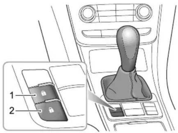
STARTINGANDDRIVING
Whenthealarmsystemisdisarmed, Presstheinterior lockingswitch(1) tolock, and presstheinterior unlocking switch(2) tounlock.
Note: The interiorlocking/unlockingswitch will not work if the alarmsystem is armed, in this case the alarm will sound.
Note: In an emergency, press and hold the interior lockingswitch form more than two seconds, the alarm will sound and all the door will lock. Press and hold unlockingswitch to silencethe alarm. The door will unlock when the switch is released.
InteriorDoorHandles
Usethedoorhandlestoopenthedoor: 1 Firstoperationofthedoorhandleunlocksthedoor. 2 Secondoperationofthedoorhandleopensthedoor.
SpeedRelatedLocking
Thisfeaturelocksallthedoorsautomaticallywhenthe roadspeedexceeds3MPH(5km/h). Thisfeatureis selectable,see'InstrumentsandControls','Security'.
Alldoorsareautomatically unlockedwhenthehandsetis removedfromthedockingstation
STARTINGANDDRIVING
T ailgate

Pressandholdtheunlockbutton(B)formorethan2 secondstoopenthetailgate.Meanwhile,theinterior tailgatelightsilluminate.
Whenthecarisfully unlocked, thetailgatecanbeopened bypressingthereleasebutton(A).
STARTINGANDDRIVING
StartingandDriving
DockingStation

DONOTremoveortouchthehandsetwhile thecarisinmotion.

The docking station is located at the instrument panel, left of the steering column and uses the following sequence to initiate the ignition and start the engine.
Position|| (I)(inserthandset)
•Thekeycanbeinsertedorremoved.
•Steering unlocked-insome casegent let turning of the steering wheel may be required.
- Individualelectricalequipmentandaccessoriescannow beoperated,e.g.electricwindows,electricmirrorsetc.
Position|| (2)
- Allinstruments, warninglights and electrical circuits are operational.
PositionIII (B)
StaringWhenhenginstartingome electricalequipmentwillbeisolatedduringcranking.
Note: Before starting the engine ensure that the gear lever is in the neutral position and the clutch pedal is pressed.
Note:Releasethehandsetimmediatelywhenengine starts.
STARTINGANDDRIVING
Themessage'FullyPressClutch'willappearintheMessage Centre,whenattemptingtostarttheenginewhenthe clutchpedalisnotpressed.
In the case of a fault with the clutch pedals switch, the brake pedal must be pressed instead and a warning is given. Them message 'Press Brake Pedal' will appear in the Message Centre. Follow the instruction and the car should start.
Handsetremoved
•Steeringislocked.
- Sidelightsandhazardwarninglightswilloperate.
Note:T oremovethehandsetwhentheengineis running,firstpresstoposition3tostoptheengine, thenpullthehandsettoturntheignitionoffand removethehandsetfromthedockingstation.
IMPORTANT
Donotpullthehandsetoutdirectlyfromthedocking station;thiswilldamagetheignitionswitchandcause theenginetobedisabled.
StartingtheEngine

NEVERstartorleavetheengineerunningin anunventilatedbuilding-exhaustgasesare poisonousandcontaincarbonmonoxide, whichcancauseunconsciousnessandmay evenbefatal.

Dieselparticulatefilterscanbedamagedif thewrongfuelisused,orifanenginemisfire occurs.Beforestartingtheengine,you shouldbeawareoftheprecautionsdetailed underthesection'DieselParticulateFilters'.
StartingtheEngine
I Switchoffallunnecessaryelectricalequipment (includingtheairconditioning).
2Checkthatparkingbrakeisfullyapplied(see 'Brake System' in this chapter).
3 Ensure neutralis selected and the clutch pedalis fully pressed.
STARTINGANDDRIVING
4Insertthehandsetintothedockingstationandpress ittoPositionIII,thenreleasethehandsetassoonas theenginehasstarted.
Note:Continueduseofthestarterwillnotonly dischargethebattery,butmaydamagethestarter motor,starterringgearordieselparticulatefilter.
DONOTpresstheacceleratorpedalwhilestartingand DONOToperatethestarterformorethan15secondsat atime.Iftheenginefailstostart,removethehandsetand waitatleast10secondsbeforetryingagain.
If the handset is not recognised by the engine immobilisations system when it is inserted into the docking station, the engine will be disabled, and 'Engine Disabled' with an warning icon will appear in the message centre (see Message Centre in Instruments and Controls chapter).
ColdClimates
Intemperaturesof-10°Candbelow,enginecrankingtimes willincrease.Itisessentialthatallunnecessaryelectrical equipmentisswitchedoffwhilecranking.
Driving
Ithinteresful economy is advisable drive the vehicle as soon as possible after starting. Remember that harsh acceleration, or labouring the engine before then normal operational temperature has been reached, can damage the engine.
StoppingtheEngine
I After bringing the cartoatop, ALWAYS apply the parking brake and select neutral.
- Apply parkingakput the EPB switch upwards until the indicator in the EPB switch illuminates, the EPB warming lamp in the instrument pack will also illuminate.
3PressthehandsettoPositionIIandrelease,thiswill stoptheengine.Pullthehandsetoutofthedockto switchofftheignition.
Afterstrenuotswingordrivingathighspeed (particularlyinhotweather), itissuggestedtoallowthe enginetoidleforafewminutesbeforeswitchingoff, which
STARTINGANDDRIVING
enablesthecoolingsystemtoworkcontinuouslytolower theenginetemperature.
STARTINGANDDRIVING
EconomicalandEnvironmentalDriving
Running-in
Theengine, transmission, brakesandtyresneedtimeto 'bed-in' and adjust to the demand so every day motoring. During the first 900 miles (1,500 km), it is essential that you drivewith consideration for the running-in process and heed the following advice:
- Donotallowtheenginetoexceed3000rpmminanygear orthevehiclespeedtoexceed72MPH(120km/h).
- Donotoperateatfullthrottleorallowtheengineto labourinanygear.
- Donotdriveataconstantspeed(eitherhighspeedor lowspeed).
- Avoidheavybrakingwherepossible. After900miles(1,500km),enginespeedscanbegradually increased.
EnvironmentProtection
Y ourcarhasbeendesignedwiththelatesttechnologyin ordertominimisetheenvironmentalimpactofexhaust emissions.
DrivingStyle
Thewayinwhichyoudriveyourcarhasasignificant bearingonenvironmentalpollution,aswellasaffectingthe amountoffuelyouuse.
Avoidfullthrottleacceleration
Steady, rather than rapid, acceleration uses considerably less fuel, reduces exhaust pollutants and minimis the weartomechanical components.
Avoiddrivingatmaximumspeed
Fuelconsumption, exhaustemissions and noise levels all increases significantly at high speeds.
Donotdriveinalowgearforlongerthan
necessary
Drivinginlowergearsusesmorefuelandcreatesmore noisChangeuptoahighergearassoonaspossible, provideditdoesNOTcausetheenginetolabour.
STARTINGANDDRIVING
Drivesmoothly
Anticipatingobstructionsandslowingdownwellin advance,avoidstheneedforunnecessaryaccelerationand harshbraking.Asmoothdrivingstylenotonlyreduces fuelconsumption,butcanreducetheemissionofnoxious gases.
Drivinginrain

Emergencybraking, accelerating and steering onslipperyroadswillreducethevehicle's handlingperformanceandgrip.
Whenrainingthewindowsmayfog, reducingvisibility(Use theAir-conditioningdemistfunction).
Gripwillbereduced, sopleasedrivecarefully.
Reducespeedwhenitrains.
Avoidaquaplaning(theeffectofafilmofwaterbetweenthetyresandtheroad)affectingsteeringandbraking performance.
Y ourMG6isequippedwithBrakeDiscWiping,activated bythewipersorrainsensor(wherefitted).Thiswillhelp
tokeepthebrakepadsanddiscsclearofwaterandhelp restorebrakeperformance.
Avoiddrivingthroughfloodsafterheavyrain,whichmay leadtoseriousdamagetothevehicle.
Howtosavefuelandextendthelifeofthe vehicle
The following a resomes suggestions on saving fuel and extending the life of the vehicles.
Maintain the correct pressure, insufficient pressure will accelerate at every wear and wasteful.
Do not necessary to lead will increase the engine load resulting in higher fuel consumption.
Avoidengineidlingforextendedperiods.
Maintainslowandsmoothaccelerationandavoidharsh accelerationchangehighergearasoonpossible.
AvoidlabouringtheengineoroverrunningChoose appropriategearsaccordingtotheroadconditions.
Avoid continuous acceleration deceleration. stop-godriving style will consumemore fuel.
STARTINGANDDRIVING
- Avoidunnecessarystoppingandbraking,maintain steadyspeedandattempttoanticipatetrafficlights. Keepanappropriatedistancefromothervehiclesto avoidemergencebrakingandreducebrakepadwear.
- Avoidtrafficcongestionandjamareasasmuchas possible.
- Donotridethebrakepedal, this can cause premature wear, overheating and increased fuel consumption.
- Maintainanappropriatespeedonthehighway.Higher speedsusemorefuel.Appropriatespeedcansavefuel.
- Maintain the correct wheel alignment. Avoid collision with the ker band reduces speed on un-mader roads. Out of specification wheel alignment not only will lead to excessivity rewear, but also increases the engine load and fuel consumption.
- Avoiddrivingonmudorbeaches. This will prevent corrosion of the vehicle underside.
- Maintain the vehicle in accordance with MG recommendations. Dirty air filters, oil etc., will reduce the engine's performance and raise fuel consumption. To extend the life of all components and reduce
operating costs, regular MGA approved maintenance is needed.
- Donotstoptheenginestraightafterhighspeedorlong ascentsortowingatrailer. Allowtheenginetoidlefor 20to10secondsdependingupdrivingloadsand conditionsAvoidhardaccelerationonacoldengine.
STARTINGANDDRIVING
Maintenance
Havethevehicleregularlyserviced
Regularlyservicingwillensureoptimumfuelconsumption andminimiseexhaustpollutants,aswellaseffectively extendingtheservicelifeofthecar.
Checktyrepressuresregularly
Under-inflatedtyresincreasetherollingresistanceofthe carwhich,inturn,increasesfuelconsumption.Overor under-inflatedtyreswearoutmorerapidlyandalsohavea detrimentaleffectonthecar'shandlingcharacteristics.
Donotcarryunnecessaryloads
The additional weight of unnecessary loadswastes fuel, especially instop/start conditions where the car is frequently required to set off from stationary.
STARTINGANDDRIVING
DieselParticulateFilter

Exhausttemperaturescanbeextremelyhigh, donotparkongroundwherecombustible materialssuchasdrygrassorleavescould comeintocontactwiththeexhaustsystem-indryweatherafirecouldresult.
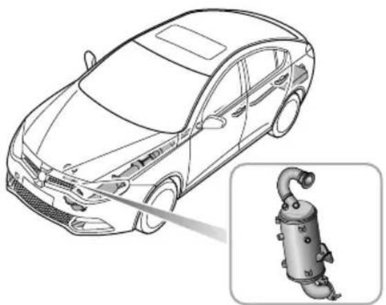
Theexhaustsystemincorporatesadieselparticulatefilter, thisconvertspoisonousexhaustemissionsfromtheengine intolessharmfulgases.
Dieselparticulatefiltersareeasilydamagethrough improperuse,especiallyifthewrongfuelisused.
Pleaseobservethefollowingprecautionstominimisethe chanceofaccidentaldamage.
Fuel
•UseONL Yfuelrecommendedforyourcar.
- Neverallowthecartorunoutoffuel-thiscouldcause seriousdamagetothefuelsystemondieselmodels.
Starting
Whendriving,youshouldpayattentiontothefollowing points:
- Donotcontinuetooperatethestarterafterafewfailed attempts, seekMGAuthorisedRepairer.
- Donotoperatethestarterifanenginemisfireis suspectedanddonotattempttoclearamisfireby pressingtheacceleratorpedal.
STARTINGANDDRIVING
- Donotattempttopushortowstartthecar.
Driving
Whendriving,youshouldpayattentiontothefollowing points:
- Donotoverloadorexcessively'rev'theengine.
- Donotstoptheenginewhenthecarisinmotionwith agearselected.
- SeekMGAuthorisedRepairerifyouthinkyourcaroil consumptionisabnormal.
•lfamisfireissuspected,orthecarlackspowerwhile driving,providedtheenginehasreacheditsnormal operatingtemperature,itmaybedrivenSLOWL Y(at riskofDPFdamage)toanMGAuthorisedRepaireror suitablyequippedservicinggarage. - Donotdriveonterrainlikelytosubjecttheunderside ofthecartoheavyimpacts.
- Allowenginetoidlefor 10secondspriortoswitching off.
Note: Anyenginemisfire, lossofengineperformance orenginerun-on, could seriously damagethe
DPF. Regularmaintenancemustbecarriedout
inaccordancewiththeschedulespecifiedinthe 'WarrantyandMaintenanceManual'.
STARTINGANDDRIVING
FuelSystem
FuelRequirements
Dieselfuelspecification:DieseltoEN590.
•MinimumCetaneRatingis49;
•MaximumBiofuelContentis7.5%.
SafetyontheForecourt

Vehiclefuelgasesarehighlyflammable and,inconfinedspaces,arealsoextremely explosive.
Alwaystakecarewhenrefuelling:
•Switchofftheengine.
- Donotsmokeoruseanakedflame.
- Donotuseamobilephone.
- Avoidspillingfuel.
•Donotoverfillthetank.
FuelFiller

FuelFillerFlap
Thefuelfillerflapislocatedontherearright-handwingand islinkedtothecentraldoorlockingsystem.Withthecar unlocked,pushontheright-handsideoftheflaptoopen.
Note: The fuelflapislockedonlywhenthecaris locked using the handset.
FuelFillerCap
Unscrewthefillercapanti-clockwiseandallowany pressureinsidethetanktoescape,beforeeremovingthe cap.
STARTINGANDDRIVING
EmergencyFuelFillerRelease

If, for any reason, the fuelfiller flap automatic unlocking mechanism fails, the flap can be released manually by pulling the emergency release of the load space area.
Removetherighthandsideliningoftheboottoseethe fuelfillerreleasecable(seeillustration).
FuelFilling

DONOTfullyfillthetankifthevehicleisto beparkedindirectsunlight,orhighambient temperature-expansionofthefuelcould causespillage.
Thedieselfillertubeisdesignedtoacceptawiderdiesel nozzle.Becarefulnottomis-fuel,seelabelonfillerflap.
Lowfuelstrategy:
• 15Litres-flashingIPKwarninglight;
•8Litres-continuousIPKwarninglight;
•3Litres-'limp-home'mode;
•Enginestops;
- Addminimum5Litrestorestorenormaldriving. Note: Neverallowthevehicletorunoutoffuel seriousdamagewilloccur.
STARTINGANDDRIVING
Re-priming:
Intheeventofdieselfueldiscontinuity(changeoffilter)
•Manuallyprimefilteruntilpumpgoessolid;
•Crankenginefor3seconds;
•Pumpagainuntilsolid;
•Crankuntilenginefires(3secondsmaximum).
Water-infuelsensor:
Intheeventofthewater-in-fuelwarninglightilluminating ontheinstrumentpackproceedtothenearestgaragefor watertobedrainedfromthefilter .Notethatwater/diesel emulsionsshouldnotbedischargedtoground.
Afterrefuelling,iftheengine runsunevenly,switchoff and seekanMGAuthorised Repairer before attempting to restart the engine.
InertiaSwitch

ALWAYScheckforfueleaksbeforeresetting theinertiaswitch.

Intheeventofacollisionorsuddenimpact,theinertia switchautomaticallycutsoffthefuelsupplytotheengine, unlocksthedoorsandturnstheinteriorlightson.In
STARTINGANDDRIVING
addition, thehazardwarninglightsflash.AnInertiaSwitch T rippedmessagewillappearinthemessagecentre.
Theinertiaswitchislocatedbehindthedriversstorage box,andcanbereachedbyfullyloweringthestowagebox.
Theswitchmustberesetbeforetheenginecanbestarted. Resettheswitchbypassingthetopoftheswitch(arrowed inillustration).
STARTINGANDDRIVING
6-SpeedManualT transmission
GearLever

Thegearpositionsareindicatedonthegearleverknob.
Synchronemshisprovidedonallgears(includingreverse). Intheneutralposition,thegearleverisspringloadedto restnaturallyinthecentreofthegatebetween3rdand4th gears.
PrecautionsWhenDriving:
I Whenswitchingbetweenforwardgearandreverse gear,youmustensurethatthevehicleiscompletelyin stationery,waitforamomentandthenfullydepress theclutchpedal,pushtheshiftleverintoneutral position,presstheleverdownandpushitleftward, thenpushitforwardintotherverseposition,slowly releasetheclutchpedaltocompletethegearshift.
2 Donotrestyourhandonthegearleverwhiledriving -pressurefromyourhandmaycauseprematurewear tothegearselectormechanism.
3Donotrestyourfootontheclutchpedalwhendriving -excessiveweartotheclutchwillresult.
4Donotholdthecarstationaryonahillbyslippingthe clutch. Thiswillwearouttheclutch.Alwaysusethe parkingbrake.
STARTINGANDDRIVING
BrakeSystem
FootBrake
Foradded safety, the hydraulic braking system operates through dual circuits. If one circuit should fail, the other will continue to function, but greater pedal pressure will be needed, and increased brake pedal travel, and longer stopping distances will be experienced. In the event of abrake failure where only one circuit is operational, the car should be brought too a halt as soon as a traffic condition safely allow. DONOT continued driving-seek MGA authorised Repairer.
ServoAssistance
Thebrakingsystemisservoassisted,alwaysbeawareof thefollowing:
- Neverallowthecartofreewheelwiththeengineturned off.
- Alwaystakeparticularcarewhenbeingtowedwiththe engineturnedoff.
- Iftheengineshouldstopforanyreasonwhiledriving, bringthecartoahaltasquicklyastrfficconditions
safelyallow, and donotpumpthebrakepedalasthe brakingsystemwillloseanyremainingservoassistance.
- Oncetheenginehasstoppeditwillloseanyremaining servoassistance,usesuitableforcetoapplythebrake pedaltostopthecarsafelyinthecurrenttraffic conditions.ContactanMGAuthorisedRepairer.
- Efficiency of the brakeservoboostercanbeaffected by numerous conditions, such as enginespeed loss. These conditions could result in extra forcerequired to operate the brake pedaltostopthecar.
WetConditions
Drivingthroughwaterorheavyrainmayadverselyaffect brakingefficientThSC(StabilityControlSystem) includes a BrakeDiscWipingfunctionwhichisactivated whenthewindscreenwipersareused. However, always keepsafedistancefromothervehiclesandintermittently applythebrakepedalinconditionswherethewipersare notused.
ElectronicBrakeForceDistribution(EBD)
You equipped ElectronBraForce Distribution, which, inordertomaintainbrakingefficiency,
STARTINGANDDRIVING
distributesbrakingforcesbetweenfrontandrearwheels, underallloadconditions.
TheEBDsystemislinkedtothebrakesystemwarning lightontheinstrumentpack.Ifthislightilluminateswhile driving,orremainsilluminatedaftertheignitionisturned onandreleaseparkingbrake,thereisafaultwiththe brakingsystem,andEBDmaynotbeavailable.Ifthis occurs,stopthecarassoonassafetypermitsandseek anMGAuthorisedRepairerimmediately.DONOTdrive thecarwiththebrakesystemwarninglightilluminated.
ElectronicBrakeAssist(EBA)
Y ourcarisequippedwithElectronicBrakeAssist,which reactstothespeedatwhichthebrakepedalisapplied.If, inanemergencysituationthebrakesareappliedfasterthan thelimitssetwithinthesystem,thenfullABSapplicationis appliedtobringthecartostopintheshortestpossible distance.
HillHoldControl(HHC)

HHChaslimitationswhensubjecttoadverse conditionssuchaswetoricysurfacesand slopesinexcessof30degrees.

HHCisnotasubstituteforparkingbrake applicationwhencarryingoutahillstart.

DonotexitthevehiclewithonlyHHC applied, it may lead to as serious accident when HHC enable.

Thecarmayrollif pull-away'isnotachieved immediatelyafterreleasingthebrakepedal. Alwaysensurethebrakepedalispressedor EPBapplieduntildriveistakenupbythe clutch.

Firmapplicationofthebrakepedalwhen stoppingisrequiredbyHHCtogenerate sufficientbrakepressureotomaintainhold.
HillHoldControlisacomfortfunction.Itworkson inclineswhenthecardetectsithascometoa'standstill status'.Oncetheclutchpedalhasbeenpresseddown and thebrakepedalreleased,thevehiclewillmaintainpressure
inthebrakingsystemfor2seconds. After this, the Hill Holdwillrelease.
HHCassistshedriverby'holding'thevehicleduringhill starts.
The following conditions must be fulfilled to activate HHC :
- Stopthevehicleonaslopeinexcessof4%andformore than2seconds.
•SCSisactiveandfaultfree.
•EPBisreleasedandfaultfree. - Clutchpedalispressed.
•IgnitionisON. - Sufficientbrakepedalapplicationforcehasbeenapplied. Ifthedriverreleasesthebrakepedalonahill, HHCwill maintainbrakepressurefor 1-2seconds,afterthisperiod thevehiclemayroll.
HHC cannot overcome physical limitations. DONOT solely rely on HHC.
Note: HHCisavailableinbothforwardandbackward directions.
Anti-lockBrakeSystem(ABS)

Absnorcophysical limitations of topping the aintoshort adistance, cornering attoohighaspeed, or thedangerofaquaplaning, i.e. wherealayer of waterprevents adequate contact between thetyresandtheroadsurface.
The purpose of the anti-lockbrakingsystem(ABS) is to prevent the wheel from locking while braking thereby enabling the divertoretainsteering control of the car.
The act has a fitted with AB must never attempt the driver into taking risk that could affect this/hersafety or other roads and cause remains the driver's responsibility to drivewith innormalsafety margins having due consideration for prevailing weather and traffic conditions.
Undernormalbrakingonditions,(wheresufficientroad surface friction exists reliably spring hearthalt withoutthewheelslocking),ABSwillnotbeactivated.
STARTINGANDDRIVING
However, should the braking force exceed the available adhesion between the teryres and theroad surface causing the wheelstolock (on slippery roads, forexample), then ABS will automatically come into operation.
This will berecognisable by a rapid pulsation felt through the brake pedal.
BrakinginanEmergency

DONOTpumpthebrakepedalatanytime; thiswillinterruptoperationoftheABSand mayincreasebrakingdistance.
Ifanemergencysituationoccurs, the drivers should apply full braking effort to even when the road surface is slippery. The anti-lockbrakingsystem will constantly monitor the rotational speed of the wheels and vary braking pressure to each wheel according to the amount of traction available. This will ensure that the wheels donotlock and that the caris brought too halt in the shortest distance for the prevailing roads surface conditions.
Note: Onsoftsurfacesuchaspowderysnow, sandor gravel, the braking distancerequired by the anti-lock brakingsystem may begreater than for non-ABS braking, even though improved steering would be experienced. This because then natural action of locked wheelson soft surfacesist build up a wedge of surfacematerial in front which assist the carto stop.
STARTINGANDDRIVING
Nomatterhowhardyoubrake,youshouldbeableto continuesteeringthevehicleasNORMAL.
ABSWarningLight.
See 'ABSWarningLight'.
Note: Thenormal(non-ABS)brakingsystemremains fullyoperationalandisnotaffectedbypartialor fulllossoftheABS. However, brakingdistancesmay increase.
ElectricParkBrake(EPB)

IntheeventofEPBmalfunctionwherethe EPBreleaseisnotpossible,DONOTtow vehiclewithallfour,orrearwheelsincontact withtheroadsurface.Damagemayoccur.

Intheeventofadischargedbattery,start theenginepriortoattemptingtoreleasethe EPB.Failureretodothismayresultindamage totheEPBsystem.
STARTINGANDDRIVING

ApplyingtheEPB
While the vehicle is stationary, the EPB can be applied.
EnsuretheEPBisappliedeverytimethevehicleisleftor parked.
• PulltheEPBswitchupwarduntiltheindicatorintheEPB switchilluminates.
•Simultaneously,theEPBindicator (P) willilluminatein theinstrumentpack.WhentheindicatorintheEPB
switchandtheEPBindicatorareilluminated, it indicate that the EPBisapplied.
- IftheEPBfailurewarninglamp

intheinstrument
packilluminates, it indicates that a faul thas been detected. Please contact an MGAuthorised Repairer immediately.
Note: Anaudiblemotornoisemaybeheardwhen applyingorreleasingtheEPB.
Not the EPB is not used for a long period, the system may perform an automatic inspection operation that will limit an audible motor noise when applied.
Caution
TheEPBcannotbeoperatedduringthelowbattery voltagecondition.
ReleasingtheEPB
Place the ignitions switch position I depressthe brake pedal, and pressthe EPB switch.
STARTINGANDDRIVING
- If the indicator in the EPB switch and the indicator in the instrument pack are extinguished, the EPB is released.
StartAssist
TheEPBcanpredictthedriver'sintentionand automaticallyreleasetheEPB.
Ifthedriver'sseatbeltisfastened, clutchpedalfully pressed, forwardorreversegearselectedandtheclutch pedalliftedwhilstpressingtheaccelerator,theEPBwill automaticallyrelease.
EmergencyBraking

Inappropriateuseoftheelectricparkbrake canleadtoaccidentsandinjuries.Donot applytheelectricparkbrakeforvehicle braking,unlessinemergency.


During emergency braking using the EPB, DO NOT insertorremovetheignitionkey, this could result in serious injury.
In the event of normal brake failure, emergency braking using the EPB can be initiated by pulling and holding the EPB switch upward.
IftheSCScanrespondactivelytotherequestformthe EPB,atspeedsinexcessofapredeterminedlimittheSCS willactivateandapplyall4brakes. Atspeedsbelowthe predeterminedlimittheEPBwillonlyactivatetherear brakes. IftheSCSisunabletorespondtotherequestfrom theEPB,thentheEPBwillonlyactivatetherearbrakes.
During emergency braking using EPB, a continual audible warning will sound to cancel the emergency braking process, release the EPB switch or press the accelerator.
STARTINGANDDRIVING
StabilityControlSystemandT raction ControlSystem
StabilityControlSystem(SCS)
SCSisdesignedtoassistthedriverincontrolofdriving direction. The SCSisautomaticallyactivated after the engine is started.
WhenSCSdetectsthatthevehicleisnotmovinginthe intendeddirection,itwillintervenebyapplyingbrakeforce toselectedwheelsorthroughtheenginemanagement systemtopreventslidingandassistinbringingthecarback totherightdirection.
T ractionControlSystem(TCS)
The purpose of electronic traction control is to aid traction, thereby helping the driver to maintain a control of the carinsituations where one or both of the driving wheels are spinning (fore example, if onewheel is on ice and the other on tarmac).
Thetractioncontrolsystemmonitorthedrivingspeedof eachwheelindividually.Ifspinisdetectedononewheel, thesystemautomaticallybrakesthatwheel,transferring
torquetotheopposite, non-spinningwheel. If both wheels are spinning, the system will reduce engines speed in order to regulate wheel rotation until traction is regained.
Note: The individual wheel braking feature of the traction control system will not operate at road speeds above 62 MPH (100 km/h). The engine torque reduction feature continues to function up to the car's maximum speed.
STARTINGANDDRIVING
SwitchingOnandOff

SCSandTCSareautomaticallyonstandbyafterengine start.
- BrieflypresstheSCSswitch(lessthan2seconds). TCSisdisabled,andthetractioncontrolindicatorwill illuminate.TheTractionControlSystemOffandthe TCSiconwillappearinthemessagecentre.
- PresstheSCSswitch(morethan2seconds).TCSand SCSarebothdisabled. ThetractioncontrolSystem indicatorwillilluminateandT ractionControlOff andtheTCSiconwillappearinthemessagecentre, followedbythemessageStabilityControlSystemOff andtheSCSiconsdisplayed.
Note: Activation of the SCS/TCS switch in excess of 10 secondswill beregarded asamis-operation.
- BrieflypresstheSCSswitch(lessthan2seconds)again, SCSandTCSwillresume,andwarninglampsextinguish.
Note: Disabling SCS and TCS will not affect the operation of ABS. Always disable TC when driving with snow chains fitted.
SCS/TCSWarningLight
Forinformationonwarninglightoperation,referto 'WarningLightsandIndicators'in'Instrumentand Controls'.
STARTINGANDDRIVING
T yrePressureMonitoringSystem (TPMS)

The TPMSisnotasubstituteforchecking tyreconditionandpressures.
Note: The TPMSwarnsoflowtyrepressures, it does notre-inflatethetyres.
SystemOperation

ThesystemiscontrolledbytheSCSsystem,which constantlymonitorsthespeedofeachwheel.If,during normaldrivingconditionswiththebrakesnotapplied, theSCSdetectsthatonewheelisrotatingfasterthanthe others,itdeducesthatthepressureofthattyrehasfallen belowthepredefinedlimitofthesystem.
Asaresult, the warning light on the instrument pack will illuminate (always yellow).
Checkyourtyresattheearliestopportunityandreinflate tothecorrectpressures. Referto'T yrePressures(Cold)'.
Note: When apuncture is detected, the system will requires sometime to analise information prior to illuminating the warning lamp.
SystemFaults
Thesystemisselfmonitoring, and if a fault is detected, the warning light on the instrument pack will flash for 90 seconds and then illuminate (always yellow).
Undercertainconditionsthewarninglightmayilluminate whenafaultisnotpresent.theseconditionsinclude:
Drivingonicyorwetsurfaces.
Frontaxlesliporexcessive lateral acceleration.
Snowchainsfitted.
Anonrecommendedtyrefitted.
TPMSnotresetaftertyrereplacement.
TPMSnotresetaftertyrepressureadjustment.
Roughterraindrivingforexcessiveperiods.
Bendingormountaintypeterraindrivingforexcessive periods.
STARTINGANDDRIVING
- Excessive luggageweight changefromwhenlastreset carriedout.
- TPMSwillnotrespondimmediatelyifatyre'blowsout'.
InitialisingTPMS
Ifreplacementtyresarefittedortyrepressureschanged, a TPMSresetisrequired-refertoTPMSresetinInstruments andControls.
Note: Inflatetyrestorerecommendedpressures and checkpriortoreset.
Note: Always carry outa TPMSreset after tyre pressure adjustment. The TPMScarries out aself learning process after a reset and therefore may not react immediately after a reset.
STARTINGANDDRIVING
CruiseControl *
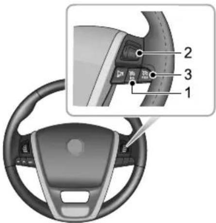
IMasterswitch
2Thumbwheel
3Resume(RES)switch
Cruisecontrolenablethedrivertomaintainaconstant roadspeedwithoutusingtheacceleratorpedal. This isparticularlyusefulformotorwaycruising,orforany
journeywhereaconstantspeedcanbemaintainedforalengthyperiod.
The following precautions must be observed when using cruisecontrol :
• DONOTattempttousecruisecontrolwhenusing reversegear.
- DONOTusecruisecontrolonwindingorslipperyroad surfaces, intherain, orintrafficconditionswherea constantspeed cannot easily be maintained.
•ALWAYSswitchchoffthemasterswitchwhenyouno longerintendtousecruisecontrol.
T oOperateCruiseControl
Thecruisecontrolsystemhasthreeswitches;twopush switches(masterswitchandresumeswitch)andathumb wheelsetswitch.Allswitchesaremountedontheright handsideofthesteeringwheel.
I Pressthemasterswitch(1), the warning light in the instrumentpack willilluminate.
2Accelerateuntilthedesiredcruisingspeedisreached (thismustbeabovethesystemsminimumoperating speedof25MPH).
STARTINGANDDRIVING
3Pressthethumbwheel(2)tosettheroadspeedinthe systemmemory.Cruisecontrolwillnowmaintainthat speedwithouttheneedtousetheacceleratorpedal.
Note: Thesetspeedheldinthecruisecontrolmemory will be cancelled when either the cruise control master switch is pressed or the ignition hand set removed.
Withcruisecontroloperating, speed can be increased by normal use of the accelerator. g. forovertaking. When the accelerator is released, roadspeed will return to the selected cruisingspeed.
Cruisecontrolwillbedisengagedwhenthebrakepedalis pressedoradifferentgearisselected.T oreturntoyour previoussetspeed,presstheRESswitch(3).
Note: Donotoperateswitchessimultaneously or for long periods, this may result in cruise control failure. Toreset the system cycle the ignition of fandon.
T oChangetheSetCruisingSpeed
Rotatethenthumbwheelupwards-thecarwillaccelerate automatically. Releasetheswitchassoonasthedesired speedhasbeenreached.
Rotateththumbwheeldownwards-thecarwill decelerateautomatically.Releasetheswitchassoonas thedesiredspeedhasbeenreached.
Alternatively, the setspeed can be increased or decreased incrementally by pushing and releasing the thumbwheel; up to increase and downtodecreasespeed. Each operation of the thumbwheel will increase or decrease the speed by approximately 1 MPH.
STARTINGANDDRIVING
IntelligentStop/StartSystem

Extremelylowbatterypowermayresultin theenginenotre-startingautomatically,or evenusingthehandsetkey.Inthisinstance, externalpowerisneededtostarttheengine orthebatterywillrequirere-charging.See thesection'EmergencyStarting'inthe 'EmergencyInformation'Chapter.

Instrumentindicationlight
2Masterswitch
3Masterswitchindicationlight
EngineStop/Starthasbeenincorporatedintovehiclesin anefforttoreduceemissions.Asthenamesuggeststhe systemwillallowtheenginetobeswitchedoffwhenengine
STARTINGANDDRIVING
powerisnotrequiredandthenautomaticallyberestarted whenitis.

Thissystemdefaults"on"atkeyin,theswitchindication lightison(3showninfig),andcanbeturnedoffbypassing themainswitch(2inthefig-thegreen"e"symbolshown above).TheMessageCentrewillshow"Stop/StartSystem OFF".
StartingtheEngine(InitialStart)
•SeeSection5, StartingandDriving, but waitfortheglow pluglamptoextinguishintheinstrumentpack.
Note: All vehicle functions will work as normal regardless of the engineer running or not.
EngineAutoStopConditions(UnderStop StartControl, warninglampon, figure1 in illustration)
•Vehicleisstationary, i.e. speed=0MPHorkm/h.
•GearboxmustbeinNeutral.
•Theclutchpedalisreleased.
• Thedriver'sdoorisclosedandseatbeltissecured.
•Thebonnetisclosed.
EngineRestart(FromStop/StartControl)
Theenginecanberestartedby:
- SwitchingoffthesystembywayoftheStop/StartOn/OffSwitch(See2onpreviouspage).
- Pressingtheclutchpedal.
• Tappingorpressingtheacceleratorpedal. - Operatingthesteeringwheel.
- Changingyourheaterandair-conditioningsettings.
Theenginewillalsobestartedautomaticallyif:
•Thebrakepedalispressedrepeatedly.
•Thebatteryconditionisreduced.
•Thevehiclestartstoroll.
• Theair-conditioninghasbeenoperated(undercertain conditions).
Note: In AUTOmode-ifthein-cartemperature is lower than target temperature at Controller
STARTINGANDDRIVING
shallallowtheenginetoauto-startwithoutany operation.
Stop/StartProhibited
- StopStartOn/OffSwitch(See2onpreviouspage) remainingOn.
•Gearposition-i.e.thevehiclemustbeinNeutral. -
Batterycondition.
-
Enginetemperature.
•Theairconditioningsystemstatus.
• Thedriver'sdoorisclosedandseatbeltissecured.
•Thebonnetisclosed. - Avehiclespeedof9MPH(15km/h)hasbeenachieved betweenstopattempts.
• Thegradientuponwhichthevehicleissat.
•DPF(DieselParticulateFilter)regeneration.
STARTINGANDDRIVING
ParkingAidSystem
UltrasonicSensorParkingAidSystem

The purpose of the parking aid to assist the driver during parking! Thesensors may not be able to detect certainty types of obstruction, e.g. narrow posts or small objects nomore than a few inches wide, small objects close to the ground, objects above the level of the boot and some objects with nonreflective surfaces.

Keepthesensorsfreefromdirt,iceandsnow. Ifdepositsbuilduponthesurfaceofthe sensors,theirperformancemaybeimpaired. Whenwashingthecar,avoidaiminghigh pressurewaterjetsdirectlyatthesensors fromcloserange.
Fourultrasonicsensors, situated in therearbumper, scan anareabehindthecarsearchingforobstructions. Ifan obstruction is detected, the sensor calculate its distance from therearofthecarandcommunicatethisinformation
tothedriverbysoundingwarningchimes.Itisimportant torememberthatthesystemisnomorethananAID toparking.Itisnotfoolproofinoperatiomoitisa substituteforobservationandpersonaljudgement.

ParkingAidOperation
With engineering parking operates automatically whenever reverse gear is selected and switched off as soon as reverse disengaged. Ashort
STARTINGANDDRIVING
'beep'willsoundwithinonesecondofreversebeing selectedtoconfirmthatthesystemisworking.
Note: Ifalonger, higherpitched, soundisemitted, for 3secondswhenreversegearisselected, this indicates afaultwiththesystem-contactMGAuthorised Repairerforassistance.
WhileReversing:
- Ifanobstructionislocatedwithinthe1.5mrangeofthe rearparkingaidsensorsor60cmofthecornersensors, thewarningcommences.Asthecarmovesclosertothe obstruction,thebeepsaretransmittedmorerapidly.
•Ifanobstructionislocatedwithinthe1.2mrangeof thefrontparkingaidsensor60cmofthecorner sensors,thewarningcommenceschiming.Asthe carmovesclosertotheobstruction,thechimesare transmittedmorerapidly. - Oncetheobstructioniswithin30cmoftherearand fronbumpethelhimesergintontinuous warningtone.
RearParkingCamera

Therearcameraisforguidanceonly, the camerarangeislimited, neverrelysolely ontheviewprovidedbythecamerawhen reversing.
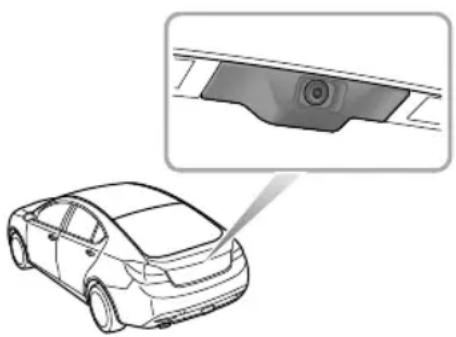
Somemodelshavearearparkingcamerafittedabovethe rearlicenceplate.Whenreversegearisselectedthe camerawilldisplayanimationeofwhatisimmediatelybehind thecar.Thisimagewillbeshownonthenavigationscreen.
STARTINGANDDRIVING
LoadCarrying

DONOTexceedthegrossvehicleweight orthepermittedfrontandrearaxleloads. Failuremayresultinvehicledamageor seriousinjury.
LoadSpace

Ensure that there are seat back rests are securely latched in the upright position when loads are carried in the load space behind theseats.

Ifthetailgatecannotbecloseddueto thetypeofcargoloaded,besuretoclose allwindowsduringdriving,selecttheface distributionmodeoftheaircondition,and settheblowertomaximumspeed,soasto decreaseexhaustfumesenteringthevehicle.
When luggage carried in the load space, always ensure heavy items are placed slowly and forward possible,
soastoavoidthecargoshiftintheeventofanaccidentor suddenstop.
Drive carefully and avoid emergency braking maneuvers.
Drivingwithboot/tailgateopenisverydangerolfs. loadingwiththetailgateopenisunavoidable,thecargoand the tailgatemustbewellsecured,andtakeappropriate measurestoppreventexhaustfumesenteringthevehicle.
IMPORTANT
Trafficregulationsmustbeobservedwhenloading cargo,ifthecargoextrudestheloadspaceappropriate warningmeasuresmustbetakentowarnotherroad users.
InternalLoading

DONOTcarryunsecuredequipment, tools orluggagethatcouldmove, causingpersonal injuryintheeventofaccident , or emergencybrakesorhardacceleration.
STARTINGANDDRIVING
Foldingtherearseatscanincreaseluggagespace, referto 'FoldtheRearSeat'describedinthe'SeatsandRestraints' chapter.
Whencargoisloadedinthevehicle,placeitataposition aslowaspossibleandensurethatitistightlysecured,so astoavoidpersonalinjurycausedbycargomovement.
EmergencyInformation
158HazardWarningDevices
159EmergencyStarting
161 VehicleRecovery
165TyreRepair
169FuseReplacement
179 BulbReplacement
EMERGENCYINFORMATION
HazardWarningDevices
HazardWarningLights

Beforeyoustoporslowthecarinanemergency,always pressthehazardwarningswitch.Allthedirection indicatorswillflashtogethertowarnotherroadusers whenyourcariscausinganobstructionorisinahazardous situation.Remembertoswitchchoffbeforedrivingaway.
WarningT riangle

Thewarningtrianglesuppliedwithyourcarisstowedin theloadspace.
If you havetostopy your carontheroad in an emergency, you must place awarning triangle approximately 50 to 150 metres (150 to 500 ft) behind the cartowarnother road users of your position.
EMERGENCYINFORMATION
EmergencyStarting
UsingBoosterCables

NEVERstarttheenginebypushingortowing.

MakesurethatBOTHbatteriesareofthe samevoltage(12volts),andthatthebooster cablesareapprovedforusewith12voltcar batteries.

Ensuresparksandnakedlightsarekeptwell awayfromtheenginecompartment.
Usingboostercables(jumpleads)fromadonorbattery, orabatteryfittedtoadonorvehicle,istheonlyapproved methodofstartingacarwithaflatbattery.
If the battery from adonor vehicle is to be used, the vehicle should be parked with their battery locations adjacent to one another. Ensure that the two vehicles do not touch.
StartingtheVehicle

Ensure that each boostercable connection is securely made. Theremust benorisk of the clips accidentally slipping from the battery terminals (as a result of engine vibration, for example), this could cause sparking, which could lead to fire ore explosion.

EMERGENCYINFORMATION
RemovetheignitionhandsetandswitchoffALLelectrical equipmentofBOTHvehicles,thenfollowtheinstructions below:
ConnecttheREDboostercablebetweenthepositive (+) terminalsofbothbatteries.Connectthe BLACKboostercablefromthenegative (-) terminabthedonobattery(A)tagoodearth point(anenginemountingorotherunpaintedsurface,forexample),atleast0.5mfromthebatteryandwell awayfromfuelandbrakelinesonthedisabledvehicle (B).
IMPORTANT
DONOTconnectaboostercabletothenegative (-)terminalofthedischargedbattery! This may resultindamagetheelectricalcomponents.
2Check that the cables are clear of moving part so both engines, then start the engine of the donor vehicle and allow it to die for a few minutes.
3Nowstarttheengineofthevehiclewiththe dischargedbattery(DONOTcranktheenginefor morethan10seconds).
4Oncebothenginearerunningnormallyallowthem toidlefortwominutesbeforeswitchingofftheengine ofdonovehiclandisconnectinghebooster cableDONOTswitchonanyelectricalcircuits onthepreviouslydisabledvehicleuntilAFTERthe boostercableshavebeenremoved.
5Disconnectingtheboostecablesmustbanexact reversals proceduresetbonnechem, i.e.disconnecttheBLACKablefromtheearthpoint onthedisabledvehicleFIRST.
Batteryeplacementreferstothesection'Battery'inthe 'Maintenance'Chapter.
IMPORTANT
NEVERturnoanyelectricalequipmentonthe startedvehiclebeforeremovingtheboostercables.
EMERGENCYINFORMATION
VehicleRecovery
T owingforRecovery
T owingEye

DONOTuseatowropethatistwisted-anyuntwistingforcecouldunscrewthefronttowingeye.


EMERGENCYINFORMATION
Y ourcarisequippedwitharemovabletowingeye,that canbeusedatthefrontortherearofyourvehicle.The towingeyeisstoredinthetoolkitbeneaththeloadspace floorwhennotinuse.
T ofitthetowingeye,removethesmallcoversetintothe bumperbypassingfirmlyonthebottomleftcorner,then screwthetowingeyeintoitsmountingbehindthebumper (seeillustration).Ensurethetowingeyeisfullytightened.
Note: Thetowingeyecovermaybesecuredtothe bumperbyaplasticcord.
Bothtowingpointsareintendedforusebyqualified recoveryspecialiststoassistintherecoveryofyour carwhenabreakdownoraccidentoccur .Theyarenot designedfortowingothervehicles,andmustNEVERbe usedtotowatrailerorcaravan.
T owingforRecovery

DONOTremovetheignitionhandsetwhile thecarisbeingtowedonfourwheels—as thiswillpreventthesteeringwheelfrom beingturned.
If your caristobetowed, most qualified recovery specialists will use wheel liftequipment to suspend the front wheels, while therear wheels remain on the ground. Otherwise may caused damage to the transmission.
However, ifitisnecessaryforthecartobetowed with allfourwheelsontheground, abidebythefollowing procedure:
Switchtheignitionontopositionltoenablethebrake lights,wipersanddirectionindicatorstobeoperated ifnecessary.If,duetoanaccidentorelectricalfault,it isconsideredunsafetoswitchtheignitionon,thecar willneedtoberecoveredonatrailer.
P2acethegearleverinneutral.
Releasetheparkbrake.
EMERGENCYINFORMATION
Without the engineer running, greater effort will be required to operate the brake pedaland turn the steering wheel. Longer stopping distances will also be experienced. Whilst towing for recovery DONOT exceed 30 MPH (50 km/h)
TowingWeight:
| Maxtrailerweight(unbraked)750kg | |
| Maxtrailerweight(braked)1600kg | |
| Maxnoseweight(T owhitchdownward load) | 100kg |
| Grosstrainweight(maximumweightof vehicleplustrailer) | 3740kg |
T oincreasestability, it is recommended that you adjust the noseweight to them a maximum limit, when loading to the maximum trailer weight.
Note: Whentowingthemaximumgrossvehicleweight can be increased by upto 100kg(22lbs), provided roadspeedislimitedtoamaximumof62MPH(100 km/h)
EMERGENCYINFORMATION
T ransporterorT railerwithRope
If your caristobetransported on the back of a trailer or transporter, it must be secured as illustrated:
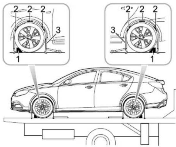
Positionthecaronthetrailer,applytheparkbrakeand placethegearleverinneutral.Fitwheelchocks(1)as shown,thenpositiontheantisliprubberblocks(2)around thecircumferenceofthetyre.
Fitthelashingstraps(3)aroundthewheelsandsecureto thetrailer.Tightenthestrapsuntilthecarissecurelyheld.
EMERGENCYINFORMATION
T yreRepair
T oolldentification

I Electricaircompressor
2Wheelboltcapremovaltool.
3T yrerepairsealant
4T owinghook
EMERGENCYINFORMATION
T yreRepair
SchematicDiagramofT yreRepair

EMERGENCYINFORMATION
I RemovethestickerontheT yreSealantBottleand attachittothesteeringwheeltoremindthedriver nottoexceed50MPH(80km/h).(Figure I)
2Connecttheairhoseoftheelectriccompressortothe tyresealantbottle.(Figure2)
3FittheT yreSealantbottle(Upright)intotheslotonthe compressor.Removethevalvedustcapfromtheflat tyreandconnectthefillerhosefromthetyresealant bottletothetyrevalve.(Figure3)
4Ensure that the powers switch of the electric air pump is switched off (i.e., press "O"), then insert the plug from the compressor into the cigarette lighter. (Figure 4)
Note: To avoid battery discharge, it is recommended to keep the vehicle engine running.
5Switchonthepowerswitchofthelectriccompressor (i.e.,press“-”),tostartpumpingsealantintothetyre. Thepressuregaugemaybrieflyreach6bar(87psi), thenthepressurebeginstodrop.(Figure6,7)
Note: Thetyresealantbottlewillbecomeempty afterapproximate30seconds.
6 Thetyreshouldreachthespecifiedinflationpressure within 10 minut Aft theorrepressuris reached, switchoffthecompressolf therequired pressure cannot bereached within 10 minutes, please disconnect compressodrive vehicle0 metre(36eep) proforwardbackward to allow thesealantospreadwithinthetyil the required pressure can still not bereached, thetyreis severely damaged and you should seek assistance from the breakdown service under circumstances should you continue your journey with adeflated tyre. Driving vehicle with adeflated tyre is extremely dangerous.(Figure8)
Not Consecutive operation of the electric air pump from a minute may result in damage to the compressor.
7Removethetyresealantbottlefromtheslotinthe compressor, disconnect the hose fromthetyrevalve,
EMERGENCYINFORMATION
removethecompressorplugfromthecigarettelighter, returnthetyrerepairkittoitsstowagetray.
8Aftersuccessfullyaddingsealanttothetyre,drive immediatelyforashorttime(aroundoneminute)this willallowthesealanttodistributeevenlyinsidethe tyre.Continuedrivinganddonotexceed50MPH (80km/h).Afterafuthertenminutes,findasafeplace tostopandrecheckthetyrepressure.Ifthetyre pressurehasdroppedtolessthan0.8bar(11.6psi), donotcontinuedriving,seekassistanceinstead.If thepressureisgreaterthan0.8bar(11.6psi)aftera 10minutesdrive,continuepumpingairintotypeuntil reachingthespecifiedtyrepressureandthencontinue driving.If1.8bar(26.1psi)cannotbereached,do notcontinuedrive,seedassistanceinstead.Donot exceed50MPH(80KPH).
Note: DONOTremoveforeignobjects(eg.screws,nails)fromthetyre.
Attheearliestopportunitygetthetyrereplacedby adealerortyrespecialistandreplacetheusedtyre sealantbottlewithanMGapprovedsealant.(Figure 11, 12)
EMERGENCYINFORMATION
FuseReplacement
Fuses
Fusesaresimplecircuitbreakerswhichprotectthecar's electricalequipmentbypreventingtheelectricalcircuits frombeingoverloaded.Ablownfusemaybeindicatethe itemofelectricalequipmentitprotectstopsworking.
Thelocationandvalueofeachfuseisshownonthechart attachedtotheundersideofthefuseboxcovers.
Checkasuspectfusebyremovingitfromthefuseboxand lookingforabreakinthewireinsidethefuse.
ShowofHealthyandBlownFuses

IMPORTANT
•Onlyreplaceafusewithoneofthesamerating.
- Ifareplacedfusefailsimmediately, refer the problem toanMGAuthorisedRepairer.
EMERGENCYINFORMATION
FuseBoxes
Thereare4fuseboxesinthevehicle:
I PassengerCompartmentFuseBox(locatedbehindthe glovebox)
2AuxiliaryFuseBox(locatedontheleftsideofthe bulkheadinenginecompartment)
3BatteryT opFuseBox(locatedonthebattery)
4EngineCompartmentFuseBox(locatedintheengine compartment)

PassengerCompartmentFuseBox

Note: The closing panel below the glovebox should be removed to gain access to the refuses.
EMERGENCYINFORMATION

CheckingorRenewingFuses
IT urnofftheignitionswitchandallelectricalequipment. Disconnectthebatterynegativecable.
2Theclosingpanelbelowthegloveboxwillneedtobe removedtogainaccesstothefuses.
Pressfusextractionocontoheadthe fuseandpulltoremovethefuseAblownfusecanbe recognisedbyabreakinthewire.
4Forablownfuse,replaceitwithasamerating.
FuseSpecification
| FunGolden | Rating | |
| F1 | 1Spare | |
| 15RantPowerSocket | ||
| 18AverseLamps,InteriorMirror,Camera | ||
| 1Spare | ||
| F5 | 5A | HeatedMirror |
| 10A6tiaSwitch | ||
| F7 | 1BAar | AccessorySocket |
| 3DARerSupply-WindowLiftFront-LH | ||
| 5AF9 | SwitchReverseLampsSwitchMasteLightMotoHeadlampLevelling,AFSSystem,PassengerAirbagON/OFFIndicator | |
| 2DPO | HeadlampMainBeams | |
EMERGENCYINFORMATION
| Code | Rating | Function |
| F11 | - | - |
| F125A | SideLamp-LH,T ailLamp-LH,Rear NumberPlateLamps | |
| F135ASwitch-EPB | ||
| F145ASwitch-SteeringWheelRemote | ||
| F15 | 20AESCLECU | |
| F1630A | Pump-WindscreenWash | |
| F17 | 30APowerSupply-PassengerSeat | |
| F1815A | Horns | |
| F1930AHeatedSeat-Front | ||
| F2020A | HeadlampDippedBeam-RH | |
| F2130APowerSupply-DriverSeat | ||
| F225AA/CControlPanel,HeatedSeat-Front | ||
| F2330APowerSupply-WindowLiftRear-LH | ||
| Code | Rating | Function |
| F2430 | APower | Supply-WindowLiftFront-RH |
| F2515 | ASpare | |
| F2625 | A | HeaterRearWindow |
| F275 | ASwitch- | gnition |
| F285 | ASpare | |
| F2915 | ASpare | |
| F3015 | ASpare | |
| F3125 | A | PassengerDoorLocks,RearDoorLocks |
| F3220 | A | HeadlampDippedBeam-LH |
| F33 | - | - |
| F34 | - | - |
| F3510 | ASpare | |
| F365 | ASideLamp-RH,TailLamp-RH | |
EMERGENCYINFORMATION
| Code | RatingFunction | |
| F375A | DiagnosticSocket | |
| F385A | Lamp-Glovebox | |
| F3910 | A | DriverDoorLocks,Motor-FuelFlapRelease,TailgateReleaseMotorRelay,Motor-T ailgateRelease |
| F4015 | ASpare | |
| F4110 | A | RearFogLamps |
| F4210 | AAirbag | ECU |
| F4320 | ASpare | |
| F445A | Interior | Mirror ,RainSensor ,PDCECU |
| F4510 | A | MultifunctionControlSwitch,MasterLightSwitch,DriverDoorSwitchPack,NavigationDisplayPower |
| F4630 | APower | Supply-WindowLiftRear-RH |
EMERGENCYINFORMATION
AuxiliaryFuseBox

FuseSpecification
| Code | RatingFunction |
| F1 | 30ADC/DCConvertor |
| F230A | Relay-ElectricWaterHeaterI, ElectricWaterHeaterElementI |
| F330A | HeadlampWashSystem |
| F420A | Relay-FuelHeater,FuelHeater |
| F5 | 20AAFSSystem |
| 5AF6 | InteriorLamp-Front,InteriorLamp-Rear,Lamp-VanityMirrors |
| F7 | 15AEntertainmentSystem |
| F810A | A/CControlPanel,Fresh/Recycle Motor |
| F910A | InstrumentPack |
EMERGENCYINFORMATION
BatteryT opFuseBox
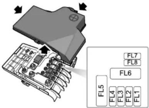
FuseSpecification
| Code | RatingFunction | |
| FL1 | 30AEPBECU | |
| FL230 | AEPBECU | |
| FL3125A | AuxiliaryFuses1,2,3,4,5,Relay-ElectricWaterHeater2,ElectricWaterHeaterElement2 | |
| FL460 | AControl | UnitGlowPlug |
| FL5 | - - | |
| FL645 | 0AMotor | -Starter |
| FL7 | EBS | |
| FL830A | Relay-ElectricWaterHeater3,ElectricWaterHeaterElement3 | |
EMERGENCYINFORMATION
EngineCompartmentFuseBox

FuseSpecification
| Code | RatingFunction |
| F1 | 15A Sensor-WideBand,ControlUnit-GlowPlug,ECU-Engine,Switch-ClutchPedal |
| F220A | PowerSupply-FuelFilter ,Bypass-EGRCooling,Actuator-VariableSwirl,Valve-ThrottleActuator,Sensor-Hot FilmAirmass,VariableGeometryTurbo Controller |
| F310A | Pump-HighPressure,Valve-Pressure Control |
| F415A | CoolingFan,Relay-Starter,Relay-FuelHeater,MasterSwitch-StartStop,Relay-ElectricWaterHeaterI,Relay-ElectricWaterHeater3,Switch-Neutral,ECU-Engine |
| F5 | 10ASpare |
| F615A | DayRunningLamps |
EMERGENCYINFORMATION
| Code | Rating | Function |
| F7 | 30A | Lamp-DirectionIndicatorFront-LH,Lamp-DirectionIndicatorRear-LH,Lamp-SideRepeater-LH,Relay-ReverseLamp,Relay-PositionLamp,Lamp-RearBrake-LH , Passenger CompartmentFuses3,12,36 |
| F820 | APassenger | CompartmentFuse7 |
| F910A | Relay-CompressorClutch-Air Conditioning,Compressor-Air ConditioningClutch | |
| F1030 | ARelay-Wiper1,Relay-Wiper2 | |
| Code | Rating | Function |
| FL1 | 200A | Alternator,EngineCompartmentFuseLinks2,7,10andFuses5,8,9 |
| FL260 | A | PassengerCompartmentFuses1,6,9,22,24,25,27,28,42,Relay-Switched |
| FL350 | A | Relay-Horn,RotaryCoupler,PassengerCompartmentFuses16,17,18 |
| FL450 | ACooling | Fan |
| FL5 | 100A | Relay-DippedBeam,Relay-RearFogLamp,PassengerCompartmentFuses19,20,21,23,30,35,37,39,40,41,43,45,46 |
| FL670 | AEHPASECU&Pump | |
| FL7 | 40ARelay-Starter,StarterMotor | |
| FL840 | ASCSECU(Pump) | |
EMERGENCYINFORMATION
| FL950A | PassengerCompartmentFuses2,5,10,13,14,15,26,38,44,Relay-HeatedRearScreen,Relay-MainBeam,Relay-Auxiliary |
| FL1040A | Relay-Blower ,Motor-Blower,A/C ControlPanel |
| FL11 | 25ASCSECU(Valve) |
| FL1250A | Relay-DippedBeam,Lamp-DirectionIndicatorFront-RH,Lamp-DirectionIndicatorRear-RH,Lamp-SideRepeater-RH,Lamps-RearBrake-RH,PassengerCompartmentFuses8,31,32 |
EMERGENCYINFORMATION
BulbReplacement
BulbSpecification
| BulbT ype | |
| HeadlampdippedbeamH755W | |
| HeadlampmainbeamH755W | |
| Xenonheadlamp | D3S35W |
| Corneringlamp | H755W |
| Directionindicators (Halogen) | WY2IW2IW |
| Directionindicators (Xenon) | WY2IW2IW |
| Sidelamp | W5W5W |
| Reverselamp | W16W16W |
| LicenceplatelampW5W5W | |
| MapreadinglampW5W5W | |
| BulbT ype | |
| Courtesylamp | W5W5W |
| Rearindicators | WY2IW2IW |
| GloveboxlampT5I.2W | |
| Loadspacelamp | C10W10W |
EMERGENCYINFORMATION
ReplacingBulbs
Beforereplacinganybulb, switchofftheignitionswitchand turnoffthelightingswitchtoavoidanypossibilityofashort circuit.
Note: Only replace bulb with the sametype and specification.
Bulbsmayshatterinuseiftheglasshasbeenscratched, orcontaminatedwithoilorperspiration.TakecareNOT totouchtheglasswithyourfingers;alwaysuseacloth tohandlethebulb.lfnecessary,cleantheglasswith methylatedspiritstoremovefingerprints.
Forotherbulbsthatarenotlisted,pleaseseekthe assistanceofaworkshopwhentheyneedtobereplaced.
FrontCourtesy&MapReadingLamp

I Useasmallflat-bladedscrewdrivertogentlyprisethe lensfromthelightunit.
2Pullthebulbsfromtheirmountingstoremove.
Replacementofthebulbisareversaloftheremoval process. Whenreplacingthelens, locatethetwoprongs atthefrontofthelensandthencarefullyflexthelensto locatethetwoprongsattherearofthelensintothelight unit. Pushthelensupwardsuntilt'clicks'intoposition.
EMERGENCYINFORMATION
RearCourtesyLamp
locatethetwoprongsattherearofthelensintothelight unit.Pushthelensupwardsuntil‘clicks’intoposition.

I Useasmallflat-bladedscrewdrivertogentlyprisethe lensfromthelightunit.
2Pullthebulbfromitsmountingtoremove.
Replacementofthebulbisareversaloftheremoval process. Whenreplacingthelens, locatethetwoprongs atthefrontofthelensandthencarefullyflexthelensto
EMERGENCYINFORMATION
GloveboxLamp *

I Reach behind the gloveboxlamp and pressit from its housing.
2Pullthebulbfromthebulbholdertoremove.
Pushthenewbulbintothebulbholder, thenpressthe gloveboxlampback into itshousing.
LoadspaceLamp
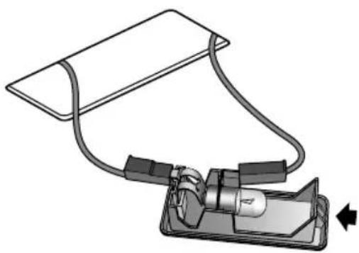
I Insertasmallflat-bladedscrewdriverintotheindent ononeofthenarrowsidesofthelens(seearrow inillustration)andcarefullypresstheunitfromits location.
2Pushandtwistthebulbtoremove.
EMERGENCYINFORMATION
Replacementofthebulbisareversaloftheremoval process.
Maintenance
186RoutineServicing
190Bonnet
191 EngineCompartment
192Engine
195CoolingSystem
197 Brakes
199PowerSteering
201 Battery
205Washers
207 Wipers
209Tyres
214CleaningandVehicleCare
MAINTENANCE
RoutineServicing
Thesafety, reliability and performance of your car will depend partly on how well it is maintained.
Y oumustensurethatmaintenanceiscarriedoutwhen requiredandaccordingtotheinformationcontainedinthe 'WarrantyandMaintenanceManual'.
Servicing
Themessagecentreshowsthenextserviceinformation. Referto'messagecentre'in'InstrumentsandControls' chapter. After the completion of each service, then next serviced display will be reset by your MGA authorised Repairer.
Note: If a service is not carried out (orthedisplay is not reset), then next serviced display will bewrong.
ServiceHistory
Refertothe 'WarrantyandMaintenanceManual' for details. Ensure your MGA authorised Repairersigns and stamp the Service History after each service.
BrakeFluidReplacement
Thebrakefluidrequiresreplacementeverytwoyears, irrespectiveofthedistancethecarhastravelled. our MGAuthorisedRepairerwillreplacethebrakefluidatthe servicenearesttototheconclusionofeachtwoyearperiod.
Note: Brakefluidreplacementwillbeanadditional cost.
CoolantReplacement
Theenginecoolant(anti-freezeandwatersolution)needs tobereplaced every four years regardless of the distance the carhastravelled. Y our MGAuthorised Repairer will replacethe coolant at the servicenearest to the conclusion of each four year period.
Note: Coolantreplacementwillbeanadditionalcost.
EmissionControl
Y ourcarisfittedwithemissionandevaporativecontrol equipmentdesignedtomeetspecificterritorialandlegal requirementscorrectenginesettingsmayadversely affectexhaustemissions,engineperformanceandfuel
consumption, as well as causing hightemperatures, which could result in damagatothecatalytic converters, DPF (diesel models) and engine.
IMPORTANT
Y oushouldbeawarethatunauthorisedreplacement, modificationortamperingwiththisequipmentbyan ownerormotorvehiclerepairercouldresultinthe manufacturer'swarrantybeingdeemedasinvalid.In addition,enginesettingsmustnotbetamperedwith.
OwnerMaintenance

Anysignificantorsuddendropinfluidlevels, oruneventyrewear,shouldbereported withoutdelay.Forfurtherinformation,refer toaMGAuthorisedRepairer.
Inadditiontotheroutineservicesreferredtoppreviously, anumberofsimplechecksmustbecarriedoutmore frequently. Youcancarryoutthesechecksyourselfand adviceisgivenonthepagesthatfollow.
DailyChecks
- Operationoflights, horn, directionindicators, wipers, washersandwarninglights.
•Operationofseatbeltsandbrakes. - Lookforfluiddepositsunderneaththecarthatmight indicatealeak.
WeeklyChecks
- Engineoillevel Note: The engineoillevel should be checked more frequently if the car is driven for prolonged periods at high speeds.
•Coolantlevel.
- Brakefluidlevel.
•Powersteeringfluidlevel.
•Screenwasherfluidlevel.
•T yrepressuresandcondition.
•Operateairconditioning.
SpecialOperatingConditions
Ifthecarisfrequentlydrivenindustyconditions, in extremeclimateswheresubzeroorveryhighambient
MAINTENANCE
temperaturesarenormal,youshouldpaymorefrequent attentiontothecar'smaintenance.Specialmaintenance operationsmayberequired(referto'Warranty and MaintenanceManual')orcontactyourMGAuthorised Repairer.
SafetyintheGarage

Coolingfansmaycommenceoperatingafter theengineisswitchedoff,andcontinue operatingforanumberofminutes.Keep clearofallfanswhileworkingintheengine compartment.
If you need to carry out maintenance, observ the followingsafety precautions at all times:
Keep you hands and clothing away from drive belts and pulleys.
If the car has been driven recently, DONOTTOUCH exhaust and cooling system components until the engine has cooled.
DONOTTOUCHelectricalleadsorcomponents while the engine running or with the handset docked.
NEVERleavetheengineerunninginarunventilatedarea exhaustgasesarepoisonousandextremelydangerous.
DO NO Work under near the air wheel changing jack as the only means of support.
Ensuresparksandnakedlightsarekeptawayfromthe enginecompartment.
Wearprotective clothing, including, where practicable, gloves made from an impervious material.
Removemetalwristbandsandewellerbeforeworking intheenginecompartment.
DONO Tallowtoolsmetapartofthecaitomake contactwiththebatteryleadsorterminals.
Because the vehicle is fitted with an automatic stop start feature, the engine may appear to be off, however, under certain conditions the engine may automatically restart. Whilst accessing the engine compartment keep hands and tem of clothing leaf from all drive belts and pulleys unless battery is disconnected.
PoisonousFluids
Fluidsusedmotorvehicles are poisonous and should not be consumed or brought into contact with open wounds.
MAINTENANCE
These include: batteryacid, antifreeze, brakeandpower steeringfluid, petrol, diesel, engineoilandwindscreen washeradditives.
Foryouwnsafety, ALWA YSreadandobeyall instructionsprintedonlabelsandcontainers.
UsedEngineOil
Prolongedcontactwithengineoilmaycauseseriousskin disorders,includingdermatitisandcanceroftheskin. Washthoroughlyaftercontact.
Usedengineoilshouldbedisposedofcorrectly.Incorrect disposalcancauseathreattotheenvironment.
MAINTENANCE
Bonnet
OpeningtheBonnet

DONOTdrivewhenthebonnetisretained onlybythesafetycatch.

I Pullthebonnetreleasehandle(A)fromtheinsideof thecar.
2Pushthelever(B)mountedonthebonnetupwardto releasethebonnetsafetycatch.
3Raisethebonnetandreleasethelever.
ClosingtheBonnet
Supportthebonnetwithtwohandsandlowerdown thebonnetuntilthedistancebetweenitandthelocking platformisapproximately30 - 40cm,thenpushwitha downwardforcetofullyclosethebonnet.
Byattemptingtoliftthefrontedgeofthebonnet,checkif thelockisfullyengagedafterclosingthebonnet.Ifitisnot fullyengaged,youmustrepeattheoperation.
WarningWhentheBonnetisOpen
Ifthebonnetisnotfullyengaged,awarningwillbedisplayed inthemessagecentrewhentheignitionisinpositionll(see MessageCentreinInstrumentsandControlschapter).
EngineCompartment

While working in the engine compartment, always observethesafetyprecautionslisted under 'SafetyIn TheGarage'.

I Windshieldwasherreservoir(bluecap)
2Coolingsystemreservoir(blackcap)
3Brakereservoir(yellowcap)
4 Lampwasherreservoir(bluecap)
5Powersteeringreservoir(blackcap)
6Engineoilfiller(yellowcap)
7Engineoildipstick(yellow)
MAINTENANCE
Engine
DieselEngineOil
ACEASpecification
UseengineoilmeetingACEAspecificationC3,toensure optimumprotectionforyourengine,alternativelyseek advicefromthemanufacturer.
Choose different viscosity of oil according to the ambient temperature in which your vehicle is operating. If temperaturerange is minimal continue using the original viscosity oil.
If you are using your vehicle in areas of extreme cold, we advise you to use oil of SAE0W-30 viscosity.
Note:Mixingoiladditiveswiththeengineoilisnot recommendedandcoulddamagetheengine.

MAINTENANCE
DieselEngineOilLevelCheckandT opUp

Drivingthecarwiththeengineoillevel ABOVEtheuppermark,orBELOWthelower markonthedipstick,willdamagetheengine.

T akecaretoavoidspillingengineoilontoa hotengine-afiremayresult!

Checktheoillevelweeklyandtopupwithoilifnecessary. Ideallytheoillevelshouldbecheckedwiththeenginecold andthecarrestingonlevelground.However,ifthecaris inuseandtheengineisalreadywarm,waitforatleasttwo minutesafterswitchingoffbeforecheckingthelevel.
I Withdrawthedipstickandwipethebladeclean.
2Slowlyinsertthedipstickandwithdrawagaintocheck thelevel,whichshouldNEVERbeallowedtofallbelow the'MIN'markonthedipstick.
3T otopup,Screwofftheoilfillercapandaddoilto maintainalevelbetweenthe'MAX'and'MIN'marks onthedipstick.
4Waitforfive minutes and then recheck the level, adding more oil if necessary - DONOTOVER-FILL DIESELENGINES WITH LUBRICANT!
5Finally,ensurethedipstickandfillercaparereplaced.
Fordieselengineoiltypeandcapacityrefertothe 'T echnicalData'Chapter.
MAINTENANCE
IMPORTANT
Checktheengineoilmorefrequentlyifthecarisdriven athighspeedsforprolongedperiods.
MAINTENANCE
CoolingSystem
CoolantCheckandT opUp

DONOTremovethereservoircapwhenthe coolingsystemishot-escapingsteamor watercouldcauseseriousinjury.
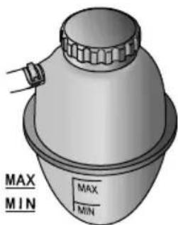
Thecoolantlevelshouldbecheckedweeklywhenthe coolingsystemiscoldandwiththecarrestingonlevel ground.
If the coolant level is below MIN level, removethe pressure cap when cold and add correct coolant mix to MAX level.
Note: Preventcoolantcomingintocontactwiththe vehiclebodywork, coolantwilldamagepaint.
If the coolant level falls appreciably during a short period, suspect leakage or overheating and rearrangement for a MG Authorised Repair to examine the car.
MAINTENANCE
CoolantSpecification
Pleaseusethecoolant(mixofwaterandantifreeze)which isrecommendedandcertifiedbythemanufacturer.Please referto'RecommendedFluidsandCapacities'.
Note: In an emergency to pup the cooling system with clean water, but be aware of the resultant reduction in frost protection and summer cooling performance. If this occurs then replenish coolant mix to the correct level at the earliest opportunity. DONOT topupor refill with other anti-freeze formulations.
Note: DONOT topuporrefillwithrustinhibitor or othercoolantadditives.
Note: Should the low coolant level warning light illuminate, check the coolant level as soon as possible.
Antifreeze

Antifreezeispoisonousandcanbefatal ifswallowed-keepcontainerssealed and outofthereachofchildren. Ifaccidental consumptionissuspected, seekmedical attentionimmediately.

Preventantifreezecomingintocontact withtheskineyes.Ifthisoccurs,rinse immediatelywithplentyofwater.
Brakes
BrakePads

DONOTrestyourfootonthebrakepedal whiledriving; thismayoverheatthebrakes, reducetheirefficiencyandcauseexcessive wear.
Forthefirst900miles(1,500km),youshouldavoid situationswhereheavybrakingisrequired.
Remember that regular servicing is vital to ensure that all the brake components are examined for wear at the correct intervals, and changed when required to ensure long terms safety and optimum performance.
Whenabrakepadwearstoapredeterminedpoint, please seekMGAuthorisedRepairertoreplacebrakepads, loss ofbrakeefficiencymayresultwhichmayresultinaserious injuryoraccident.
Atthetimeofbrakepadreplacementitisrecommended thatthebrakepadwearindicatorsensor/sbereplaced.
BrakeFluidCheckandT opUp

Brakefluidishighlytoxic-keepcontainers sealedandoutofthereachofchildren. Ifaccidentalconsumptionofbrakefluid issuspected,seekmedicalattention immediately.

Preventbrakefluidcomingintocontact withtheskinoreydfthisoccurs,rinse immediatelywithplentyofwater.
Thebrakefluidlevelshouldbecheckedweeklywhenthe systemiscoldandwiththecaronlevelground.
Thefluidlevelcanbeseenthroughthereservoirneck andshouldbemaintainedasclosetothe'MAX'markas possible.Donotallowtheleveltodropbelowthe'MIN' mark.
Note: Brakefluidwilldamagepaintedsurfaces.Soak upanyspillagewithanabsorbentclothimmediately andwashtheareawithamixtureofcarshampooand water.
MAINTENANCE

BrakeFluidSpecification
Usethebrakefluidwhichisrecommendedandcertified bythemanufacturer.See'RecommendedFluidsand Capacities'.
IMPORTANT
Thebrakefluidmustbereplacedeverytwoyears.
PowerSteering
PowerSteeringFluidCheckandT opUp

Powersteeringfluidishighlytoxic-keep containerssealedandoutofthereach ofchildren.Ifaccidentalconsumptionof fluidissuspected,seekmedicalattention immediately.

Ifpowersteeringfluidshouldcomeinto contactwiththeskinoreyes,rinse immediatelywithplentyofwater.
Thefluidlevelshouldbecheckedeveryservid this shouldbedonebeforetheengineistartedwhenthe systemiscoldandwiththefrontwheelspointingstraight ahead.
Wipehillecapleanprevendirfromentering theeservoRemovehillecapandsingle lint-freecloth,wipethedipstickclean.Refitthecapfully andemovagaincheckfluiddevnecessary, topupwithafluidmeetingspecificationuntilthelevelis
between the upper and lower marks on the dipstick (see illustration).
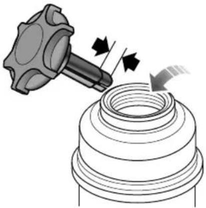
No Powersteeringfluidwilldamagepainted surfacesSoakupanspillagewithabsorbentcloth immediatelyandwashtheareawithamixtureofcar shampooandwater.
MAINTENANCE
IMPORTANT
T akecarenottospillpowersteeringfluidontoahot engine,afiremayresult.
PowerSteeringFluidSpecification
Usethepowersteeringfluidwhichisrecommended and certifiedbythemanufacturer .Referto‘Recommended FluidsandCapacities’.
Battery

T oaccessthebattery, releasethefixingsandmovethetop ofthebatterycoverasideasshowninillustration.
BatterySafety
Batteriescontainsulphuricacid,whichisbothcorrosive andpoisonous.Wearsuitableprotectiveequipmentwhen handlingbatteriestoprotectyoureyes,skinandclothing.
Ifaspillageoccurs:
- Onclothingortheskin-removeanycontaminated clothingimmediately,flushtheskinwithlargeamounts ofwater,andseekmedicalattentionurgently.
• Intheeyes-flushwithcleanwaterimmediatelyforat least 15minutes.Seekmedicalattentionurgently. - SwallowingbatteryacidcanbefatalunlessIMMEDIA TE actionistaken-seekmedicalattentionurgently.
BatteryDisconnectionandReplacement
Note: NEVERruntheenginewiththebattery disconnected, or disconnectthebatterywhilethe engineisrunning.
Batteriescontainsulphuricacid,whichisbothcorrosive andpoisonous.Ifabatteryrequiresreplacementcontact anMGAuthorisedRepairer.Onlyfitareplacement
MAINTENANCE
batteryofthesametypeandspecificationastheoriginal tomaintainthecorrectvehiclefunctionality.
Before disconnecting or removing the battery, ensure that the starters switch and all electrical equipment is turned off.
Disconnectthenegative(-)cablefirstandthenthepositive (+)cable(whenreconnecting,connectthepositivecable firstandthenenegativecable).
When lifting the battery from the car, keep the battery upright at all times.
Makesureboththebatteryclampingplateandretaining straparefittedsecurely,thiswillpreventthebatteryfrom movingintheeventofanaccidentorsuddenstop.
Note: Tomaintainthecorrectfunctionality of Stop/Start, the battery sensor requires resetting after battery replacement. Please consult an MG Authorised Repair to reset the battery sensor, it takes 4 hours at least forth the sensor to get the exact status information of the battery. Failure to adhere to the abovewill inhibit the stop/start functionality.

Usdatterlantifel
environment, must be disposed using approved method. They should be recycled by a professional company. Please consult an MGA authorised repairer for more details.
BatteryCharging
Note: DONOT chargethe battery if it is suspected of being frozen.
Asthebatteryages, it may not retain its charge as effectively as when it was new. Car that are used infrequently, or are used excessively for short journey motoring, or operation in cold climates, may need the battery to be charged regularly.
PreChargingBatteryAppearanceCheck : : :
- Iftheshellisbrokenorthereisaleak, DONOTcharge thebatteryandreplaceitafterfindingthereason.
- Iftheterminalisbroken, DONOTchargethebattery andreplaceitafterfindingthereason.
•DONOTattempttochargea'bulging'or'distorted' battery.
Pri: chargingsunterminalsfedeom corrosion, applypetroleumjellytoterminaltohelp preventcorrosion.
ChargingNotes:
Always fanfeglass when connecting disconnectingabatterycharger.
•AlwaysensuretheretheareaiswellventilatedEnsure thechargingbatteryhasadequatespaceanddoesnot 'over-heat'.
DONO Smoke the vicinity of charging battery, and ensures parks and naked lights are kept well away from the engine compartment.
- Beforecharging,connectthepositivecableatfirst. Aftercharging,disconnectthenegativecableatfirst.
BatteryChargingOperation:
Note: When charging oremergency starting always ensure then negative lead has a good connection to a body earth away from the battery (refer to the section 'Emergency starting in the Emergency Information' Chapter).
- Ifchargingthebatterywhilstonthevehicle,please connectthebatterychargernegativeleadtothevehicle bodyensuringagoodconnection.
- Ensure all terminals are free from corrosion.
MAINTENANCE
- Only suitable battery chargers can be used - please consult an MGA authorised repairer for details.
- During the charging process the battery temperature MUST NOT exceed 40°C.
- DONOTattempttochargeabatteryattemperatures below0°C.
BatteryMaintenance

DONOTleaveelectriccomponentsswitched onwhentheengineisnotrunning,the batterymaybecomeflatandyouwillnotbe abletostarttheengine.
The battery is designed to be maintenance free, so topping-up is unnecessary.
Note: If the vehicle is stored more than 1 month, removal the earth lead from the battery. Makes sure that the ignition switch has been turned off before connecting or disconnecting the earth lead. When connecting the earth lead again, the vehicle must be left in a locked state for 4 hour store-calibrated
batterycondition.Failuretoadheretowthiswillinhibit thestop/startfunctionality.
Washers
WindscreenandFrontLampWasherCheck andT opUp

Somescreenandfrontlampwashproducts areflammable, particularly if higher undiluted concentrations are exposed to sparks. Donot allows screen was to come into contact with naked flames or sources of ignition.

Whenfillingthewasherreservoiravoid spillagesontopaintedsurfaces,damagemay occur.ifspillageoc cursorfluidcomesinto contactwithbareskinpleasewashwith cleanwaterimmediately.

The washer reservoir is located for the offside of the engine compartment and suppliesthewindscreenwashers and headlampwashers.
Checkthefluidlevelatweeklyintervalsandtopupwhen low.
Note: DONOTuseananti-freezeorvinegar/water solutioninthewasherreservoir-anti-freezewill damagepaintworkwhilevinegarwilldamagethe windscreenwasherpump.
MAINTENANCE
IMPORTANT
- Usethewasherfluidwhichisrecommendedbythe manufacturer,orthewashermotormaybecome damagedbyfreezingifnon-recommendedwasher fluidisusedinwinter.
- Thewasherpumpsmaybecomedamagedifused whenthereservoirisempty.
- Thewipersmaydamagethewindscreenifusedwhen dry-alwaysensurethereisadequatefluidinthe reservoir.
WasherNozzles
Operatethewasherperiodically to check if the windshield washernozzles are clean and they are in the correct direction.
Thewindshieldwashernozzlesareconfiguredduringthe production,sogenerallythereisnoneedforadjustments.If necessary,aneedlecanbeinsertedintothejetorificeand leveredgentlyintopositionsothatthesprayisdirected towardtherequiredareaofthewindscreen.
Thefrontlampwashernozzles * cannotbeconfigured.
If thenozzleisobstructed, insertaneedleorthinmetal wireintotheholetoremovetheobstruction.
WashingFluidSpecification
Usethewashingfluidrecommendedandapprovedby themanufacturer. Referto 'RecommendedFluidsand Capacities'.
Wipers
WindscreenWiperBlades
| IMPORTANT |
| •Grease,siliconandpetrolbasedproductsimpairtheblade’swipingcapability.Wasthewiperbladesinwarmsoapy waterandperiodicallychecktheircondition. |
| •Cleanthewindscreenfrequently,DONOTusewiperstoremovestubbornoringraineddirt,itwillreducetheir effectandtheirlifespan. |
| •Ifsignsofhardnessorcrackingintherubberarefound,orifthewipersleavestreaksorunwipedareasonthescreen, thenthewiperbladesshouldbereplaced. |
| •Cleanthewindscreenregularlywithanapprovedglasscleanerandensurethescreenisthoroughlycleanedbefore fittingreplacementwiperblades. |
| •Onlyfitreplacementwiperbladesthatareidenticaltotheoriginalspecification. |
| •Cleaniceandsnowfromaroundwipersandensuretheyarenotfrozenorotherwisestickingtothewindscreen beforeattemptingtooperatethem. |
MAINTENANCE
ReplacingFrontWiperBlades

I Liftthewiperarmawayfromthewindscreen.
2Squeezethetwolocatingtagsandpivotthebladeaway fromthewiperarm.
3Unhookthebladefromthewiperarmanddiscard.
4Locatethetipofthenewwiperbladeintheslotinthe wiperarm.
5Pivotthewiperbladetowardsthearmuntilthe locatingtagsengage.
6Checkthatthebladeisfittedcorrectlytothearm beforepositioningonthewindscreen.
T yres
Overview
•T akeextracarewhenusingnewtyresforthefirst500 km.
- Avoidexcessivecorneringatspeed.
- Regularlychecktyresfordamageandforeignobjects-removeanyforeignobjectsfromthetread.
- Avoidtyrecontactwithoils,greaseandfuel.
- Ensurevalvecapsarealwaysfitted.
- Ifthetyreistoberemovedalwaysmarkthetyre/wheel orientationtoensurecorrectrefitment.
NewT yres
Newtyresmaynothavethesameadhesionpropertiesof theoldtyres, pleasetakeextracarefor500km. Thisaction couldbenefittyrelife.
T yreorrimdamagecanhappenunnoticed.Ifabnormal vibrationsorhandlingisexperienced,oryouthinktyreor rimdamagehasoccurredpleasecontactanMGAutorised Repairer.
DirectionalT yres
Directionaltyresaremarkedwith'directionofrotation'(DOR).T omaintainhandlingcharacteristics,tyre performance,lowroadnoiseandextendtyrelife, tyres/wheelsmustalwaysbefittedwithindicationarrow showingthecorrect'DOR'.
MAINTENANCE
T yreLife
Correcttyrepressuresandmoderatedrivingstylecan extendtyrelife.
Recommendations:
- If the vehicle is restored for a lengthy time, please move at least one time in two weeks to 'rotate theetyres'
•T yrepressures should be checked regularly when the tyres are cold. - Avoidcorneringatexcessivespeeds.
• Regularlychecktyresforabnormalwearpatterns.
The following factors can affect the property life.
T yrePressures
Incorrecttyrepressurescanresultinpoordriving characteristicsandashortenedtyrelife.T yrepressures shouldbecheckedatleastonceamonth,andonceprior toeachlong-distancejourney.
DrivingStyle
Excessivelyharshaccelerationandbrakingwhilstcornering willreducetyrelife.
WheelBalance
Shakingorvibrationofthevehicleorsteeringmechanism canindicateoutofbalancewheels.Itisimportanttorectify thisquicklyastopreventwearonsteeringandsuspension componentsandshortentyrelife.
WheelAlignment
Incorrectwheelalignmentcancauseexcessivetyrewear and affect vehiclesafety. If the tyresshowsignsofabnormal wearseek advice from MGA authorised repairer.
CaringforY ourT yres

DEFECTIVETYRESAREDANGEROUS! DONOTdriveifanytyreisdamaged, isexcessivelyworn,orisinflatedtoan incorrectpressure.
Alwaysdrivewithconsiderationfortheconditionofthe tyres,andregularlyinspectthetreadandsidewallsforany signofdistortion(bulges),cutsorwear.
Note: If possible, protect tyres from contamination by oil, grease and fuel.
T yrePressures

Itisadvisedtochecktyrepressurespriorto anylongjourneys.
Check the pressures monthly, whentetyres are cold.
Ifitisnecessarytocheckthetyreswhentheyarewarm, youshouldexpectthepressurestohaveincreasedby0.3 to0.4bar(4.35to5.8psi).Inthesecircumstances,NEVER
letairoutofthetyresinordertomatchtherecommended pressures(cold).
Valves
Keepthevalvecapsscreweddownfirmly-thypreventdirt fromenteringthevalve.Checkthevalveforleaks(listen foratell-talehissing)whenyoucheckthetyrepressure.
PuncturedT yres
Y ourvehicleisfittedwithtyreswhichmaynotleakif penetratedbyasharpobject,providedtheobjectremains inthetyre.Ifyouareawareofthisoccurring,reducespeed immediatelyanddrivewithcautionuntilthenecessary repairscanbeundertaken.
Note: If the sidewallofthetyreisdamagedor distorted, plaatyimmediatelpot attemptarepair.
MAINTENANCE
T yreWearIndicators
T yresfittedasoriginalequipmenthavewearindicators mouldedintothetreadpatternatseveralpointsaround thecircumference.

Whenthetreadhasworndownto 1.6mm, the indicators willcometothesurfaceofthetreadpattern, producing theeffectofacontinuousbandofrubberacrossthewidth ofthetyre.
IMPORTANT
AtyreMUSTbereplacedassoonasawearindicator becomesvisible.
ReplacementT yres

DONOTreplacethewheelswithwheels ofanyothertype.Alternativewheels,ofa differentspecification,mayadverselyaffect thecar'sdrivingcharacteristics.
Alwayshavereplacementwheelsandtyresbalancedbefore use.
WheelFitmentRotation
Inordertobalancetyrewear, it may benefit from rotating tyreposition. Wheelscan beswapped front to ear in ordertoevenspread tyrewear across all tyres.
MAINTENANCE
![graph TD A["Top cylinder"] --> B["Bottom cylinder"] C["Top cylinder"] --> D["Bottom cylinder"] style A fill:#f9f,stroke:#333 style C fill:#f9f,stroke:#333 style B fill:#ccf,stroke:#333 style D fill:#ccf,stroke:#333](/content/2026/05/883879/images/55083e777d480b436badb9712b8ff470b95ca30643628d3195214e53ccc97ce0.jpg)
DirectionaltyresCANNOTbeswappedfromsidetoside.
SnowChains
Unsuitablesnowchainscoulddamagethetyres, wheels, suspension, brakesorbodyworkofyourcar.
Inuse, always observethe following precautions:
•Fitsnowchainstothefrontwheelsonly.
- Thethicknessofsnowchainsshouldn'texceed20mm.
•Alwaysadheretothesnowchainfittingandretensioning instructionsandthespeedlimitationsforvaryingroad conditions.
•DONOTexceedspeedsof50km/h.
- Avoidtyredamageandexcessivechainwearby
removingsnowchainswhendrivingonsnowfreeroads.
Note: If you drive on the snowy and icy roads, it is recommended to use winter tyres. Consultant MG Authorised Repairer for details.
MAINTENANCE
CleaningandVehicleCare

Observeallsafetyprecautionsoncleaning products;donotdrinkfluidsandkeepthem awayfromtheeyes.
WashingY ourCar

Somehighpressurecleaningsystemswill penetratedoor, windowandsunroofseals, and damagelockmechanisms. DONOTaim waterjetsdirectlyatcomponentsthatmight beeasilydamaged.
Inordertopreservethepaintfinishonyourcar, please observethefollowingcarepoints:
•DONOTusehotwatertowashthecar.
•DONOTusedetergentsorwashingupliquid.
• Inhotweather, DONOT was the car indirect sunlight.
- When using a hose, DONOT aim the water directly at window, door or sun roof seals, orthrough wheel apertures onto the brake components.
Ifthecarisparticularlydirty,useahosetoflushgrimeand gritfromthebodywork,priortowashing.Then,washthe carusingcoldorlukewarmwatercontainingagoodquality washandwaxshampoo.Alwaysuseplentyofwaterto ensurethatgritisflushedfromthesurfaceandnotground intothepaintwork.Afterwashing,rinsethebodywork withcleanwateranddryoffwithachamoisleather.
Cleaningtheunderside

DONOTuseahighpressurehosetoclean theenginecompartment-damagetothe car'selectronicsystemsmayoccur.
Fromtimetotime, but particularly during winter months when salthas been used on theroads, use ahosetowash the underside of the car. Flush away accumulation of mud and thoroughly clean those areas where debriscane easily collect (wheel arches and panel seams, forexample).
Removingtarspots
Usewhitespirittoremovetarspotsandstubborngrease stainsfromthepaintwork. Thenwashtheareaimmediately withsoapywatertoremovealltracesofthespirit.
Bodyprotection
Afterwashing,examinethepaintworkfordamage.Ifthe damagehasrevealedbaremetal,useacolouredprimer first,thenapplythecorrectcolourbasecoatandfinish offwithalacquerpencil,ifappropriate.Carryoutthis treatmentafterwashingbutbeforepolishingorwaxing.
Moreextensivedamagetopaintorbodyworkmust berepairedinaccordancewiththemanufacturer's recommendations.Failuretodothiswillinvalidatethe Anti-CorrosionWarranty.Ifindoubt,askyourMG AuthorisedRepairer.
Polishingthepaintwork

DONOTusecarpolishcontainingcoarse abrasives—thesewillremovethepaintfilm anddamagetheglossfinish.
Occasionally treathe paintsurface with approve polish containing the following properties:
Verymildabrasivestoremovesurfacecontamination withoutremovingordamagingthepaint.
Fillingcompoundsthatwillfillscratchesandreduce theirvisibility.
Waxtoprovideaprotectivecoatingbetweenthepaint andtheelements.
Note: If possible, avoid applying polishor wax product stowindow glass and rubber seals.
Wiperblades
Washinwarmsoapywater.DONOTusespiritorpetrol basedcleaners.
Windowsandmirrors
Regularlycleanallwindows,insideandout,usingan approvedglasscleaner.
Windscreen: In particular, clean the outside of the screen with glass clean after washing the car with wash and wax products, and before fitting new wiper blades.
Reascreenclearthinsidewithsoftlothusingsidetosidemotiontoavoiddamagingtheheatingelements.
MAINTENANCE
Note: DONOTscrapeoruseabrasivecleanersonthe insideoftherearscreen—thiswilldamagetheheating elements.
Mirrors: Washwithsoapywater. Useaplasticscraperto removeice. DONOTuseabrasivecleaning compounds ormetalscraper.
CleaningtheInterior
Plasticmaterials
Cleanplastic-faced materials with diluted upholstery cleaner, then wipewith adamp cloth.
Note: DONOTpolishdashboardcomponents—these shouldremainnon-reflective.
Carpetandfabrics
Cleanwithdilutedupholsterycleaner-testaconcealed areafirst.
Leather
Cleanleathertrimwithwarmwaterandanon-detergent soap.Dryandpolishtheleatherwithadry,clean,lint-free cloth.
Note: DONOTusepetrol, detergents, furniture creams or polishes as cleaning agents.
MAINTENANCE
Instrumentpack, clock, audiosystemand navigationdisplay
Cleanwithadryclothonly.DONOTusecleaningfluids orsprays.
Airbagmodulecovers

DONOTallowtheseareastobefloodedwith liquidandDONOTusepetrol,detergent, furniturecreamorpolishes.
T oprotectdamagetotheairbagSRS, the following areasshouldbecleanedsparinglywithadampclothand upholsterycleanerONLY:
•Steeringwheelcentrepad.
• Areaofdashboardcontainingthepassengerairbag.
- Areaofroofliningandfrontpillarfinisherswhich enclosethesideheadimpactprotectionmodules.
SeatBelts

DONOTusebleaches, dyesorcleaning solventsonseatbelts.
Extendthebelts,thenusewarmwaterandanon-detergent soaptocleanAllowthebeltstodrynaturally;DONOT retractthemoushecaunittheyarecompletelydry.
TechnicalData
220TechnicalDataDimensions
221Weights
222 MajorParametersofEngine
223RecommendedFluidsand Capacities
224WheelAlignment(Unladen Condition)
224 WheelandTyre
224TyrePressures(Cold)
TECHNICALDATA
T echnicalDataDimensions
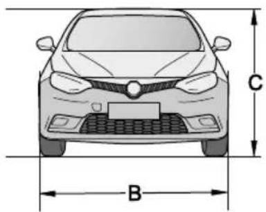

| Item,unitsParameter | |
| OveralllengthA,mm4657 | |
| OverallwidthB,mm1827 | |
| OverallheightC(unladen),mm1467 | |
| WheelbaseD,mm | 2705 |
| FrontOverhangE,mm950 | |
| RearOverhangF ,mm998 |
| Item,unitsParameter | |
| Frontwheeltrack,mm1557 | |
| Rearwheeltrack,mm1555 | |
| Minimunturningirclediameter,kerb-to-kerb | 11.8 |
| Fueltankcapacity,l | 62 |
| Luggagecapacity,l | 429 |
| Wheelnuttorque,Nm | 11530 |
Weights
| Item,units | Parameter | ||
| SSETSE | |||
| Personincab,person5 | |||
| Dieselmodelsunladenvehicle weight(kerb),kg | 152115251539 | ||
| Grossvehicleweight,kg | 2140 ( Diesel ) | ||
T owingWeights
| Item,units | Parameter |
| D1.9 | |
| T owinglimitun-braked,kg | 750 |
| T owinglimitbraked,kg | 1600 |
| T owinghitchmaximumdownload,kg | 100 |
TECHNICALDATA
MajorParametersofEngine
| Item,units | Vehicle |
| D1.9 | |
| Bore×Stroke,mm×mm | 80×92 |
| Capacity,l | 1.850 |
| Compressionratio | 15.8:1 |
| Maximumpower ,kw | 110 |
| Enginespeedtodevelopmaximumpower,rev/min | 4000 |
| Maximumtorque,Nm | 350 |
| Enginespeedtodevelopmaximumtorque,rev/min l 800-2600 | |
| Idlespeed,rev/min800±50 | |
| Fueltype,RON/CNEN590 | |
RecommendedFluidsandCapacities
| NameFluidT ype | Capacity | |
| Engineoil,l | C35W-305.0 | |
| Enginecoolant,l | Glycol(OAT) | 7.7 |
| T ransmissionFluid,L | MTF942.5 | |
| Brakefluid,IDOT40.55 | ||
| Powersteeringfluid,IPentosinCHF202 | 1.1 | |
| Windshieldwasherfluid,IQx35 | ||
| Headlampwasherfluid,l | ||
| Airflow fluid, refrigerant,g |
3.8
Qx35
TECHNICALDATA
WheelAlignment(UnladenCondition)
| ItemParameter | ||
| Front | Camberangle | -0°28' ± 45' |
| Castorangle | 3°37' ± 45' | |
| T otaltoe | 0°10' ± 6' | |
| Kingpininclination(nonadjustable) | 12°54' ± 45' | |
| Rear | Camberangle | -1°10' ± 45' |
| T otaltoe | 0°24' ± 6' | |
T yrePressures(Cold)
| Wheel | Allloadconditions |
| 205/60R16 | |
| Front Wheel | 2.2bar(32psi) |
| Rear Wheel | 2.2bar(32psi) |
WheelandT yre
| Wheelsize | 7J×16 |
| T yresize | 205/60R16 |
A
ABS (Anti-lock braking system) 30, 139, 141, 145
ABS warning light 30, 141
Accessory power socket 53
Adaptive Frontlighting System (AFS) 14, 25, 36
Aerial (antenna) removal 84
Air conditioning 60-73
Air distribution 63-72
Air recirculation 66,72
Air vents 60 - 62
Airbag SRS 27, 44, 92, 96, 217
Airbag SRS service information 96 - 102
Airbag SRS warning light 27
Airbags driver and front passenger 96 - 98
Airbags - side head curtain 100
Airbags - side pelvis/thorax 99
Alarm status indicator light 32
Alarm system 32, 117-120
Ambient temperature 10, 152, 187
Anti-freeze 186, 196
Anti-theft alarm indicator 117, 118
Ashtray 53, 55
ATC (Automatic temperature control)* 67-73
Audio system equipment 76-84
Automatic courtesy lights 51, 52
Automatic dimming interior mirror 47
AUTO lights 34
AUTO air conditioning 67, 68
Auto store - audio controls 80-81
AUX devices - audio 78, 81, 82
Average fuel consumption 17, 19, 24
Average speed 17, 19, 21
B
Backrest adjustment - seats 88, 89
BAND button - audio controls 77, 80, 81
Battery - handset 12, 113, 114
Battery charging 203
Battery disconnection and removal 201 - 202
Battery maintenance 204
Battery safety 201
Blower (ATC)* 63-70, 152, 155
Blower (ETC) 63-66, 152, 155
Bonnet opening 190
Booster cables 159
BDW (Brake Disc Wiping) 127, 137
Britax Child Seats 109
Brake fluid 30, 186, 187, 197, 198, 223
Brake fluid specification 198, 223
Brake lights 162
Brake pad wear indicator 15, 197
Brakes 126, 138, 143, 146, 155, 187, 197 - 198
INDEX
Braking in an Emergency 140
Bulb replacement 179-183
Bulb specification 179
C
Camera - rear parking 154
Capacities 223
Car washes 46, 84
CD player 76-78, 82, 84
Central door locking 132
Centre vents 60-62
Check engine warning light 30, 31
Child proof locks 116
Child restraints and seats 97, 103-110
Cleaning - car interior 214-217
Cleaning - paintwork 214-215
Clock 10, 25, 81, 217
Cold climates 124
Coolant check, top-up and replacement 195
Coolant level warning light 8, 13
Coolant specification 196, 223
Cooling system 188, 191, 195-196
Courtesy lights 51, 52, 179
Cruise control* 28, 148-149
Cubby box 56
Cup holders 57
Current journey 17, 19, 20
D
Daily checks 187
Data - Technical 220-224
Daytime Running Lamps 35
Default - trip computer 24
Defrosting/demisting 63-68, 72, 152
Dial sweep 24
Diesel fuel 132-134
Diesel Particulate Filter (DPF) 16, 123, 124 130, 131, 152, 187
Digital speed 17, 18, 24
Dimensions 220
Dimmer switch - instruments 35
Dipped beam headlights 13, 23, 34-36, 38, 39
Dipstick 191, 193, 199
Direction indicator bulb - front 13, 179
Direction indicator bulb - rear 179
Direction indicator lights 7, 13, 17, 27, 38-39
Disabling passenger air-bag 102
Docking station 12, 115, 117, 120, 122-124
Door mirror - folding 45
Door mirrors 45
E
Ejecting a CD 77, 84
Ejecting USB device safely 84
Electric seats* 89
EBA (Electronic Brake Assist) 138
EBD (Electronic brake force distribution) 137-138
ESCL (Electronic Steering Column Lock) 31
ETC (Electronic temperature control) 63-66
Electronic Parking Brake 15, 32, 124, 139, 141 - 143
Emergency key unlocking 112, 113, 115
Emergency fuel filler release 133
Emission control 186
Engine compartment 170, 176, 188, 191
Engine compartment fuses 176
Engine fault light 31
Engine coolant temperature gauge 8
Engine oil 187, 189, 191-194, 223
Environmental driving 126
F
Face level vents 64, 67, 70,
Fast forward - audio controls 83
Fog lights - rear 23, 27, 35, 37
Foot brake 137
Front courtesy and reading lights 180
Front cup-holder 57
Front wiper operation 40-42
Front wiper blade replacement 208
Fuel consumption 17-19, 126-129
Fuel cut-off switch (inertia switch)134-135
Fuel filler 9, 132, 133
Fuel filling 133
Fuel gauge 8, 9, 19
Fuel specification 132
Fuel system 12, 130, 132
Functions - Vehicle Options menu 17, 24
Fuses, replacement and colour 169-178
Fuse box (passenger compartment) 170-173
Fuse boxes (engine compartment) 176-178
Fuse box auxiliary 174
Fuse box battery top 175
G
Gauges 8-9
Gearbox number 3
Gear change display 10, 24
Gear change warning indicator 16, 24
Gear lever 122, 136, 162, 164
Global window open and close 119
INDEX
Glovebox 55
Glovebox light bulb 179, 182
Glow plug warning - diesel 33, 151
H
Handset 12, 23, 34, 50, 51, 102, 112-123, 132, 149,
150,160, 162, 188.
Handset battery 12, 112-113
Hazard warning lights 2, 27, 39, 123
Hazard warning triangle 158
Head restraints 87, 90, 104
Headlight bulb 179
Headlight flash 38
Headlight levelling 35-36
Headlight washers 42
Headlights 34-36, 38,39
Heated mirrors 45
Heated rear screen 45, 63-65, 67-68, 71-72
Heated seats 73, 89
Heavy loads 127
Hill Hold Function 138-139
Horn 7, 44, 117
|
Identification numbers 3
Ignition 7, 9, 10, 16, 17-18, 20, 22, 27-38, 40, 44, 45, 49, 51, 53, 78, 100, 113, 114 122-124, 138, 139, 142, 143, 149, 160, 162, 180, 190, 204, 205.
Indicators 27, 38, 39, 158, 162, 179, 187.
Inertia switch (Fuel cut-off switch) 134-135
INFO button - audio controls 77, 81, 84
Instrument dimmer 35
Instrument pack 7, 8, 10, 34, 35, 37-38, 100, 117, 124, 134, 138, 142, 146, 148, 151, 217.
Intelligent Stop/Start 14, 150.
Intelligent TPMS (Tyre Pressure Monitoring System)*
21, 22, 29, 146-147.
Interior lights 51, 119, 134
Interior locking switch 120
ISOFIX restraints 103, 106-109
J
Jump leads 159
Jump starting 159
K
Key - emergency 102, 112, 113, 115
L
Lamp failure and monitoring 13, 39
Language 24
Lap time 17, 19
Last journey 18, 20
Lighting switch 7, 34
Lights off delay 13, 23
Load carrying 155
Loadspace light bulb 179, 182
Locking 21, 22, 50, 117-120.
Locking - speed related 22
Low oil pressure 28
Lumbar support adjustment 88, 89
M
Main beam headlights 17, 27, 35, 38
Maintenance 129, 186-217
Manual transmission 3, 136
Manual front seats 88
Map reading lights 51,179, 180
Menu 20-25
Message centre 8-10, 12, 18, 24, 27-37, 39, 41, 117-
118, 123-124, 135, 145, 151, 186, 190.
MFC - Multi-Function Control 78
Mirrors - door 45
Mirrors - interior 47
Mirrors cleaning 215
Mirrors - folding 45
Mislock 117, 118
MIX button - audio controls 77, 79, 83
MONO control - ATC 68, 70, 71
MUTE button - audio controls, 77, 79
N
Next service 17, 18, 21, 186
Number plate lamps (license plate) 179
O
Odometer 10
Oil level check - engine 28, 187, 193
Oil top-up 193
Opening the bonnet 7, 190
P
Parking aid 153-154
Parking camera* 154
Parking brake 15, 22, 123, 124, 136, 138
Particle/pollen filter 61
INDEX
Passenger air - bag disabling 102
Passenger compartment fuses 170-173
Poisonous fluids/gases 123, 130, 188, 196, 201
Polishing the paintwork 215-217
Power socket 53-54
Power steering fluid check and top-up 187, 189, 199-200, 223
Power - operated seats* 89
Power - operated windows 49-50
Pre-tensioners 95
Programmed Wash/Wipe 22, 41
Punctured tyres 146, 211
R
Rain sensor ® 42
Rear courtesy lights 52, 181
Rear fog guard light 23, 27, 35, 37
Rear parking camera parking aid * 154
Rear screen heater 45, 63-65, 67-68, 71-72
Rear seats - folding 90, 156
Rear view mirror - automatic dimming 47
Rear view mirror - manual 47
Rear window isolation switch 49-50
Recirculation 63, 64, 66, 67, 68, 72
Recommended fluids 223
Recovery 161-164
Remote handset 12, 23, 34, 50, 51, 102, 112-123, 132, 149, 150, 160, 162, 188
Remote handset battery 12, 113, 114
Reverse light bulbs 179
Routine servicing 186-187
Running-in 126
S
Safety in the garage 188
Search tuning - audio controls 77, 80
Seat belt pre - tensioners 95
Seat belts 14, 27, 28, 86, 91, 92-95
Seat belt warning 28
Seat cushion height (driver only) 89
Seat heaters 73, 89
Seats - manual 88
Seats - power operated 89
Security 22, 112, 117-120
SEL button - MFC (Multi-function Control) 78
Service information 21, 101, 186
Service interval display 18, 21
Setting date and time 79
Side airbags 99
Side head impact protection 100
Sidelight bulb 179
Side lamps 34, 35, 51, 123
Single point entry 22, 119
Slip Control System (SCS) 29, 30, 137, 139, 143-146
Snow chains 213
Sound settings - audio controls 79
Speed warning 12, 21, 24
Speed locking 22
Speedometer 8-9
SRC - Source button - audio controls 77, 78, 80, 82
Starting - diesel models 123, 124, 130, 151
Steering column adjustment 43
Steering lock 31
Sun visor 48
System fault warning lamp 32
T
TA - Traffic Announcement button - audio controls 77, 79
Tailgate opening |21
Technical data 219-224
Temperature control - ATC* 70
Temperature control - ETC 64
Temperature gauge 8
Thirty-minute play function -audio controls 78
Top tether restraint 104, 109, 110
Towing eyes 161, 162
Towing weights 221
Towing for recovery precautions 161-163
Track search - audio controls 83
Traction control (TC) 29, 30, 144-145
Transporter or trailer lashing 164
Transmission 3, 126, 136, 162, 223
Trip computer 11, 17, 18, 20, 24
Trip recorder 19, 21
Tyre pressures 19, 21, 29, 127, 129, 146, 147, 168, 187, 210, 211, 224
TPMS - (Tyre Pressure Monitoring System)* 21, 29, 146, 147
Tyre wear indicators 212
Tyres 22, 126, 127, 129, 139, 140, 146, 147, 209-213
U
Units 22
Unlocking 22, 23, 50, 102, 118-120, 133
Upper anchorage seat belt height adjustment 94
USB socket 82-83
Used engine oil 189
V
Vanity mirrors 48
Variable delay - wipers 41-42
Vehicle identification number 3
INDEX
Vehicle information display 11
Vehicle options 21-22
Vehicle recovery 161-164
Ventilation 60-61
VIN plate 3
W
Warning lights 12, 26-27, 122, 187
Warning messages and symbols 11-16
Warning triangle 158
Washer jets, fluid and top-up 187, 191, 205-206, 223
Washing the car 214
Weekly checks 187
Weights 221
Welcome lights (Find my car) 23
Wheels 16, 212, 213
Wheel alignment 210
Windows 49-50, 119, 215
Window lift switch 7, 45, 49-50
Windows - cleaning 215
Windscreen washer check and top-up 187, 191, 205-206, 223
Windscreen wipers 40-42, 127, 137, 187, 206-208
Wiper blade - cleaning 207
Wiper blade replacement 208
Wiper controls 40-42

MG MOTOR UK
Lowhill Lane, Longbridge,
Birmingham B31 2BQ
www.mg.co.uk




- VEHICLDENTIFICATIONINFORMATION....3
- I INSTRUMENTSANDCONTROLS....5
- INSTRUMENTS AND CONTROLS OVERVIEW....6
- INSTRUMENPACK....8
- MESSAGECENTRE....10
- CONTENTS
- 3AUDIOSYSTEM....75
- AUDIOSYSTEM * 76
- 4SEATSANDRESTRAINTS....85
- SEATS......86
- SEABELTS....92
- AIRBAGSUPPLEMENTARYRESTRAINTSYSTEM....96
- CHILDRESTRAINTS....103
- 5STARTINGANDDRIVING......III
- ROUTINESERVICING....186
- BONNET....190
- ENGINECOMPARTMENT....191
- ENGINE....192
- COOLINGSYSTEM....195
- BRAKES....197
- POWERSTEERING....199
- BATTERY....201
- WASHERS....205
- WIPERS....207
- TYRES....209
- INTRODUCTION
- THEOWNER'SHANDBOOK
- STATUSATTIMEOFPRINTING
- SYMBOLSUSED
- WARNING
- IMPORTANT
- NOTE
- PREFACE
- ASTERISK
- ILLUSTRATIONINFORMATION
- INANEMERGENCY
- REMEMBERTHEBREAKDOWNSAFETYCODE
- VEHICLEIDENTIFICATIONINFORMATION
- VEHICLEIDENTIFICATION
- VEHICLEIDENTIFICATIONLOCATION
- VINLOCATION
- ENGINENUMBERLOCATION
- MANUALTRANSMISSIONNUMBERLOCATION
- INSTRUMENTSANDCONTROLS
- ENGINECOOLANTT EMPERATUREGAUGE
- T ACHOMETER
- SPEEDOMETER
- FUELGAUGE
- T EMPERATUREANDCLOCK
- GEARPOSITIONDISPLAY/GEARCHANGE REMINDER
- ODOMETER
- WARNINGINFORMATION
- WARNINGMESSAGESANDSYMBOLS
- DOOR,BONNET,BOOTOPENINDICATOR
- T RIPCOMPUTER
- NEXTSERVICE
- DIGITALSPEED
- FUELCONSUMPTION
- RANGETOEMPTY
- AVERAGEFUELCONSUMPTION
- AVERAGESPEED
- TRIP1, TRIP2
- LAPTIME
- CURRENTJOURNEY
- LASTJOURNEY
- SPEEDWARNING
- FUNCTIONRESET
- SECURITY
- SPEEDLOCKING
- UNLOCKING
- PROGWASHWIPE
- UNITS
- CONSUMPTION
- DISTANCE
- LIGHTSOFFDELAY
- FINDMYCAR
- LANGUAGE
- GEARDISPLAY
- DIALSWEEP
- GEARCHANGE
- TRIPCOMPUTER
- DIGITALCLOCK
- MAINBEAM-BLUE
- SIDELAMPS-GREEN
- DIRECTIONINDICATORS-GREEN
- REARFOGGUARDLIGHT-YELLOW
- SRSWARNING-RED
- SEATBELTWARNING-RED
- CRUISECONTROL-Y ELLOW/GREEN
- LOWOILPRESSURE-RED
- ALTERNATORCHARGEWARNING-RED
- T YREPRESSUREMONITORINGSYSTEM(TPMS)
- STABILITYCONTROLSYSTEMTRACTIOCONTROL OPERATIONANDFAULTWARNING-YELLOW
- STABILITYCONTROLSYSTEM/T RACTIONCONTROLOFF
- ABSWARNING-Y ELLOW
- BRAKESYSTEMWARNING-RED
- CHECKENGINE/DRIVEBYWIREWARNING-Y YELLOW
- MALFUNCTIONINDICATORLAMPWARNING-Y YELLOW
- EPBSTATUSWARNING-RED
- EPBFAULTWARNING-Y ELLOW
- STOP/STARTACTIVEINDICATION-GREEN
- SYSTEMFAULTWARNING/ALARMSTATUSWARNING-YELLOW/RED
- GLOWPLUGWARNING-Y ELLOW
- PASSENGERAIRBAGOFF-Y ELLOW
- PASSENGERAIRBAGON-Y ELLOW
- LIGHTINGSWITCH
- AUTOLIGHTS
- SIDE,T AILANDLICENCEPLATELIGHTS
- HEADLIGHTS
- HEADLIGHTCOURTESYDELAY
- DAYTIMERUNNINGLIGHTS
- DYNAMICHEADLAMPLEVELLING
- CORNERINGLAMPS
- FOGLIGHTS
- REARFOGLIGHTS
- DIRECTIONINDICATOR/MAINBEAMLEVER
- DIRECTIONINDICATORS
- HEADLIGHTMAINANDDIPPEDBEAM
- HEADLIGHTFLASH
- LAMPFAILURE
- HAZARDWARNINGLIGHTS
- WIPERSANDWASHERS
- FRONTWINDSCREENWIPERCONTROLS
- INTERMITTENTWIPE/AUTOMATICWIPE
- NORMALSPEEDWIPE
- FASTSPEEDWIPE
- SINGLEWIPE
- PROGRAMMEDWASHWIPE
- HEADLAMPWASHERS
- RAINSENSOR
- STEERINGCOLUMN
- STEERINGCOLUMNADJUSTMENT
- HORN
- MIRRORS
- EXTERIORMIRRORS
- HEATINGELEMENTS
- MIRRORFOLDING
- INTERIORREAR-VIEWMIRROR
- VANITYMIRROR
- WINDOWS
- POWEROPERATEDWINDOWSWITCH
- WINDOWOPERATION
- REARWINDOWISOLATIONSWITCH
- ONE-T OUCH'DOWN
- ONE-T OUCH'UPAND'ANTI-T RÂP
- LAZY-LOCK'FUNCTION
- INTERIORLIGHT
- FRONTCOURTESYANDMAPREADINGLIGHTS
- MANUALOPERATION
- AUTOMATICOPERATION
- REARCOURTESYLIGHT
- POWERSOCKET
- FRONTPOWERSOCKET
- ACCESSORYPOWERSOCKET
- STORAGEEQUIPMENT
- ASHTRAY
- GLOVEBOX
- CUBBYBOX
- CUPHOLDER
- FRONTCUPHOLDER
- AIRCONDITIONING
- VENTILATION
- PARTICLE/POLLENFILTER
- VENTS
- CENTREVENTS
- SIDEVENTS
- CENTRECONSOLEVENTS
- ELECTRONICAIRCONDITIONINGCONTROLS
- AIRCONDITIONINGDISPLAY
- TEMP
- AIRDISTRIBUTION
- BLOWER
- HEATEDREARSCREEN
- A/CBUTTON
- AIRRECIRCULATION
- DEFROST/DEMIST
- AUTOMATICAIRCONDITIONINGCONTROLS
- CONSOLEPANEL
- AUTOCONTROL
- MANUALCONTROL
- DUALZONET EMPERATURECONTROL
- MONOCONTROL
- OFF
- HEATEDFRONTSEATS
- AUDIOSYSTEM
- BASICOPERATION
- ON/OFFPOWER
- 30MINUTESPLAYFUNCTION
- SELECTMODE
- VOLUMECONTROL
- SOUNDSETTINGS
- MUTE
- TA(T RAFFICANNOUNCEMENT)
- SELECTFOLDER
- SETTINGDATEANDTIME, AUTOVOLUME, RDS (RADIODATASYSTEM)
- RADIOOPERATION
- SELECTSOURCE
- BAND
- RADIOT UNING
- SEARCHT UNINGMODE
- MANUALT UNINGMODE
- PRE-SETT UNINGMODE
- STORESTATION
- MANUALSTORE
- AUTOSTORE
- RDS(RADIODATASYSTEM)SETTINGS
- CD,USB,AUXPLAYER
- THECOMPACTDISC(CD)PLAYERFITTEDTOYOUR CARWILLONLYACCEPTONEDISCATATIME
- LOADINGACD
- CONNECTUSB
- CONNECTAUX
- T RACKSEARCH
- FASTFORWARD/REWIND
- MIX
- INFO
- EJECTINGCD
- REMOVEUSB
- ANTENNA
- SEATSANDRESTRAINTS
- SEATS
- CORRECTSEATINGPOSITION
- HEADRESTRAINTS
- HEATINGFRONTSEAT
- FOLDINGTHEREARSEATS
- REARSEATBACKRESTS'LATCHSECURE'INDICATORS
- SEATBELTS
- SAFETYINFORMATION
- FASTENINGTHEBELT
- RELEASINGTHEBELT
- UPPERANCHORAGEHEIGHTADJUSTMENT
- CHECKINGSEATBELTS
- REPLACINGSEATBELTS
- SEATBELTPRE-TENSIONERS
- AIRBAGSUPPLEMENTARYRESTRAINT SYSTEM
- AIRBAGS
- AIRBAGDEPLOYMENT
- FRONTSEATSIDEAIRBAGS
- SIDEHEADIMPACTPROTECTIONAIRBAGS
- AIRBAGWARNINGLIGHTANDMESSAGES
- SERVICEINFORMATION
- DISABLINGTHEPASSENGERAIRBAG
- DISPOSINGOFTHEVEHICLE
- CHILDRESTRAINTS
- CHILDRESTRAINTINSTRUCTIONS
- T OP-TETHERCHILDRESTRAINTSYSTEMS
- STARTINGANDDRIVING
- HANDSETS
- HANDSETBATTERYREMOVINGANDREFITTING
- EMERGENCYKEY
- CHILD-PROOFLOCKS
- LOCKORUNLOCKTHECHILD-PROOFLOCKS
- ALARMSYSTEM
- LOCKINGTHECAANDARMINGTHEALARM
- LOCK
- MISLOCK
- IFTHEALARMSOUNDS
- GLOBALWINDOWOPENANDCLOSE
- INTERIORDOORHANDLES
- SPEEDRELATEDLOCKING
- T AILGATE
- DOCKINGSTATION
- POSITION|| (I)(INSERTHANDSET)
- POSITION|| (2)
- POSITIONIII (B)
- HANDSETREMOVED
- STARTINGTHEENGINE
- COLDCLIMATES
- DRIVING
- STOPPINGTHEENGINE
- ECONOMICALANDENVIRONMENTALDRIVING
- RUNNING-IN
- ENVIRONMENTPROTECTION
- DRIVINGSTYLE
- AVOIDFULLTHROTTLEACCELERATION
- AVOIDDRIVINGATMAXIMUMSPEED
- DONOTDRIVEINALOWGEARFORLONGERTHAN
- NECESSARY
- DRIVESMOOTHLY
- DRIVINGINRAIN
- HOWTOSAVEFUELANDEXTENDTHELIFEOFTHE VEHICLE
- MAINTENANCE
- HAVETHEVEHICLEREGULARLYSERVICED
- CHECKTYREPRESSURESREGULARLY
- DONOTCARRYUNNECESSARYLOADS
- DIESELPARTICULATEFILTER
- FUEL
- STARTING
- FUELSYSTEM
- FUELREQUIREMENTS
- SAFETYONTHEFORECOURT
- FUELFILLER
- FUELFILLERFLAP
- NOTE: THE FUELFLAPISLOCKEDONLYWHENTHECARIS LOCKED USING THE HANDSET
- FUELFILLERCAP
- FUELFILLING
- INERTIASWITCH
- 6-SPEEDMANUALT TRANSMISSION
- PRECAUTIONSWHENDRIVING
- BRAKESYSTEM
- FOOTBRAKE
- SERVOASSISTANCE
- WETCONDITIONS
- ELECTRONICBRAKEFORCEDISTRIBUTION(EBD)
- ELECTRONICBRAKEASSIST(EBA)
- ANTI-LOCKBRAKESYSTEM(ABS)
- BRAKINGINANEMERGENCY
- ABSWARNINGLIGHT
- ELECTRICPARKBRAKE(EPB)
- APPLYINGTHEEPB
- CAUTION
- RELEASINGTHEEPB
- STARTASSIST
- EMERGENCYBRAKING
- STABILITYCONTROLSYSTEMANDT RACTION CONTROLSYSTEM
- STABILITYCONTROLSYSTEM(SCS)
- T RACTIONCONTROLSYSTEM(TCS)
- SCS/TCSWARNINGLIGHT
- T YREPRESSUREMONITORINGSYSTEM (TPMS)
- SYSTEMOPERATION
- SYSTEMFAULTS
- INITIALISINGTPMS
- CRUISECONTROL
- T OOPERATECRUISECONTROL
- T OCHANGETHESETCRUISINGSPEED
- INTELLIGENTSTOP/STARTSYSTEM
- STARTINGTHEENGINE(INITIALSTART)
- ENGINEAUTOSTOPCONDITIONS(UNDERSTOP STARTCONTROL, WARNINGLAMPON, FIGURE1 IN ILLUSTRATION)
- ENGINERESTART(FROMSTOP/STARTCONTROL)
- STOP/STARTPROHIBITED
- PARKINGAIDSYSTEM
- ULTRASONICSENSORPARKINGAIDSYSTEM
- PARKINGAIDOPERATION
- WHILEREVERSING
- REARPARKINGCAMERA
- LOADCARRYING
- LOADSPACE
- INTERNALLOADING
- EMERGENCYINFORMATION
- HAZARDWARNINGDEVICES
- WARNINGT RIANGLE
- EMERGENCYSTARTING
- USINGBOOSTERCABLES
- STARTINGTHEVEHICLE
- VEHICLERECOVERY
- NOTE: THETOWINGEYECOVERMAYBESECUREDTOTHE BUMPERBYAPLASTICCORD
- T OWINGFORRECOVERY
- T RANSPORTERORT RAILERWITHROPE
- T YREREPAIR
- T OOLLDENTIFICATION
- FUSEREPLACEMENT
- FUSES
- SHOWOFHEALTHYANDBLOWNFUSES
- FUSEBOXES
- PASSENGERCOMPARTMENTFUSEBOX
- CHECKINGORRENEWINGFUSES
- BULBREPLACEMENT
- REPLACINGBULBS
- NOTE: ONLY REPLACE BULB WITH THE SAMETYPE AND SPECIFICATION
- FRONTCOURTESY&MAPREADINGLAMP
- REARCOURTESYLAMP
- GLOVEBOXLAMP
- LOADSPACELAMP
- ROUTINESERVICING
- SERVICING
- SERVICEHISTORY
- BRAKEFLUIDREPLACEMENT
- COOLANTREPLACEMENT
- EMISSIONCONTROL
- OWNERMAINTENANCE
- DAILYCHECKS
- WEEKLYCHECKS
- SPECIALOPERATINGCONDITIONS
- SAFETYINTHEGARAGE
- POISONOUSFLUIDS
- USEDENGINEOIL
- BONNET
- OPENINGTHEBONNET
- CLOSINGTHEBONNET
- WARNINGWHENTHEBONNETISOPEN
- ENGINECOMPARTMENT
- ENGINE
- DIESELENGINEOIL
- ACEASPECIFICATION
- COOLINGSYSTEM
- COOLANTCHECKANDT OPUP
- COOLANTSPECIFICATION
- ANTIFREEZE
- BRAKES
- BRAKEPADS
- BRAKEFLUIDCHECKANDT OPUP
- BRAKEFLUIDSPECIFICATION
- POWERSTEERING
- POWERSTEERINGFLUIDCHECKANDT OPUP
- POWERSTEERINGFLUIDSPECIFICATION
- BATTERY
- BATTERYSAFETY
- BATTERYDISCONNECTIONANDREPLACEMENT
- USDATTERLANTIFEL
- BATTERYCHARGING
- PRECHARGINGBATTERYAPPEARANCECHECK
- CHARGINGNOTES
- BATTERYCHARGINGOPERATION
- BATTERYMAINTENANCE
- WASHERS
- WASHERNOZZLES
- WASHINGFLUIDSPECIFICATION
- WIPERS
- WINDSCREENWIPERBLADES
- REPLACINGFRONTWIPERBLADES
- T YRES
- OVERVIEW
- NEWT YRES
- DIRECTIONALT YRES
- T YRELIFE
- T YREPRESSURES
- WHEELBALANCE
- WHEELALIGNMENT
- CARINGFORY OURT YRES
- VALVES
- PUNCTUREDT YRES
- T YREWEARINDICATORS
- REPLACEMENTT YRES
- WHEELFITMENTROTATION
- SNOWCHAINS
- CLEANINGANDVEHICLECARE
- WASHINGY OURCAR
- CLEANINGTHEUNDERSIDE
- REMOVINGTARSPOTS
- BODYPROTECTION
- POLISHINGTHEPAINTWORK
- WIPERBLADES
- WINDOWSANDMIRRORS
- INSTRUMENTPACK, CLOCK, AUDIOSYSTEMAND NAVIGATIONDISPLAY
- AIRBAGMODULECOVERS
- TECHNICALDATA
- A
- B
- INDEX
- C
- D
- E
- F
- G
- R
- S
- T
- U
- V
Brand : MG
Model : 6 (2015)
Category : Car