
Media Composer 7 - Photo/Video Software Avid - Free user manual and instructions
Find the device manual for free Media Composer 7 Avid in PDF.


| Product Type | Professional video editing software |
| Platform | Windows 7, Mac OS X 10.6 or later |
| Supported Resolutions | Standard definition (SD), high definition (HD) including 720p and 1080p, 2K, and uncompressed HD |
| Supported Frame Rates | 23.976p, 24p, 25p, 29.97p, 29.97i, 50i, 59.94p, 59.94i, 60p, 60i |
| Video Codecs | Avid DNxHD, DV, DVCPRO HD, XDCAM, HDV, MPEG-2, uncompressed |
| Audio Tracks | Up to 16 tracks of audio (mix of mono, stereo, and 5.1 surround) |
| File Formats (Import) | OMF, AAF, MXF, QuickTime, AV 3D, Photoshop PSD, BMP, TIFF, JPEG, PNG, WAV, AIFF, MP3 |
| File Formats (Export) | OMF, AAF, MXF, QuickTime, Windows Media, MPEG-4, H.264, DPX, TIFF, and tape via Digital Cut tool |
| Real-time Effects | Yes, includes transitions, 3D effects, keying, color correction, and audio effects with real-time playback |
| Color Correction | Advanced color correction tools with curves, wheels, and secondary color correction |
| Audio Mixing | Integrated audio mixer with EQ, dynamics, reverb, and support for external controllers |
| Multi-Camera Editing | Supports up to 9 cameras with automatic grouping and real-time switching |
| Script-Based Editing | ScriptSync and PhraseFind for speech-to-text alignment and search |
| Collaboration | Avid Interplay integration for shared storage and workflow management |
| System Requirements (Windows) | Intel Core i7 or Xeon, 8GB RAM (16GB recommended), NVIDIA Quadro graphics, dedicated media drives |
| System Requirements (Mac) | Mac Pro with Intel Xeon, 8GB RAM (16GB recommended), ATI Radeon HD or NVIDIA GeForce, dedicated media drives |
| Input/Output Hardware Support | Avid Nitris DX, Avid Mojo DX, or third-party I/O devices via Open I/O |
| Included Manual | 999-page PDF user guide covering editing, effects, audio, and workflows |
| License | Perpetual or subscription license; supports floating licenses for shared environments |
| Maintenance and Updates | Avid Support and upgrade plans available |
Frequently Asked Questions - Media Composer 7 Avid
User questions about Media Composer 7 Avid
0 question about this device. Answer the ones you know or ask your own.
Ask a new question about this device
Download the instructions for your Photo/Video Software in PDF format for free! Find your manual Media Composer 7 - Avid and take your electronic device back in hand. On this page are published all the documents necessary for the use of your device. Media Composer 7 by Avid.
USER MANUAL Media Composer 7 Avid
Avid ^® Media Composer ^®
Editing Guide
Legal Notices
Product specifications are subject to change without notice and do not represent a commitment on the part of Avid Technology, Inc.
This product is subject to the terms and conditions of a software license agreement provided with the software. The product may only be used in accordance with the license agreement.
This product may be protected by one or more U.S. and non-U.S patents. Details are available at www.avid.com/patents.
This document is protected under copyright law. An authorized licensee of Avid Media Composer may reproduce this publication for the licensee's own use in learning how to use the software. This document may not be reproduced or distributed, in whole or in part, for commercial purposes, such as selling copies of this document or providing support or educational services to others. This document is supplied as a guide for Avid Media Composer. Reasonable care has been taken in preparing the information it contains. However, this document may contain omissions, technical inaccuracies, or typographical errors. Avid Technology, Inc. does not accept responsibility of any kind for customers' losses due to the use of this document. Product specifications are subject to change without notice.
Copyright © 2013 Avid Technology, Inc. and its licensors. All rights reserved.
The following disclaimer is required by Apple Computer, Inc.:
APPLE COMPUTER, INC. MAKES NO WARRANTIES WHATSOEVER, EITHER EXPRESS OR IMPLIED, REGARDING THIS PRODUCT, INCLUDING WARRANTIES WITH RESPECT TO ITS MERCHANTABILITY OR ITS FITNESS FOR ANY PARTICULAR PURPOSE. THE EXCLUSION OF IMPLIED WARRANTIES IS NOT PERMITTED BY SOME STATES. THE ABOVE EXCLUSION MAY NOT APPLY TO YOU. THIS WARRANTY PROVIDES YOU WITH SPECIFIC LEGAL RIGHTS. THERE MAY BE OTHER RIGHTS THAT YOU MAY HAVE WHICH VARY FROM STATE TO STATE.
The following disclaimer is required by Sam Leffler and Silicon Graphics, Inc. for the use of their TIFF library:
Copyright © 1988–1997 Sam Leffler
Copyright © 1991–1997 Silicon Graphics, Inc.
Permission to use, copy, modify, distribute, and sell this software [i.e., the TIFF library] and its documentation for any purpose is hereby granted without fee, provided that (i) the above copyright notices and this permission notice appear in all copies of the software and related documentation, and (ii) the names of Sam Leffler and Silicon Graphics may not be used in any advertising or publicity relating to the software without the specific, prior written permission of Sam Leffler and Silicon Graphics.
THE SOFTWARE IS PROVIDED "AS-IS" AND WITHOUT WARRANTY OF ANY KIND, EXPRESS, IMPLIED OR OTHERWISE, INCLUDING WITHOUT LIMITATION, ANY WARRANTY OF MERCHANTABILITY OR FITNESS FOR A PARTICULAR PURPOSE.
IN NO EVENT SHALL SAM LEFFLER OR SILICON GRAPHICS BE LIABLE FOR ANY SPECIAL, INCIDENTAL, INDIRECT OR CONSEQUENTIAL DAMAGES OF ANY KIND, OR ANY DAMAGES WHATSOEVER RESULTING FROM LOSS OF USE, DATA OR PROFITS, WHETHER OR NOT ADVISED OF THE POSSIBILITY OF DAMAGE, AND ON ANY THEORY OF LIABILITY, ARISING OUT OF OR IN CONNECTION WITH THE USE OR PERFORMANCE OF THIS SOFTWARE.
The following disclaimer is required by the Independent JPEG Group:
This software is based in part on the work of the Independent JPEG Group.
This Software may contain components licensed under the following conditions:
Copyright (c) 1989 The Regents of the University of California. All rights reserved.
Redistribution and use in source and binary forms are permitted provided that the above copyright notice and this paragraph are duplicated in all such forms and that any documentation, advertising materials, and other materials related to such distribution and use acknowledge that the software was developed by the University of California, Berkeley. The name of the University may not be used to endorse or promote products derived from this software without specific prior written permission. THIS SOFTWARE IS PROVIDED "AS IS" AND WITHOUT ANY EXPRESS OR IMPLIED WARRANTIES, INCLUDING, WITHOUT LIMITATION, THE IMPLIED WARRANTIES OF MERCHANTABILITY AND FITNESS FOR A PARTICULAR PURPOSE.
Copyright (C) 1989, 1991 by Jef Poskanzer.
Permission to use, copy, modify, and distribute this software and its documentation for any purpose and without fee is hereby granted, provided that the above copyright notice appear in all copies and that both that copyright notice and this permission notice appear in supporting documentation. This software is provided "as is" without express or implied warranty.
Copyright 1995, Trinity College Computing Center. Written by David Chappell.
Permission to use, copy, modify, and distribute this software and its documentation for any purpose and without fee is hereby granted, provided that the above copyright notice appear in all copies and that both that copyright notice and this permission notice appear in supporting documentation. This software is provided "as is" without express or implied warranty.
Copyright 1996 Daniel Dardailler.
Permission to use, copy, modify, distribute, and sell this software for any purpose is hereby granted without fee, provided that the above copyright notice appear in all copies and that both that copyright notice and this permission notice appear in supporting documentation, and that the name of Daniel Dardailler not be used in advertising or publicity pertaining to distribution of the software without specific, written prior permission. Daniel Dardailler makes no representations about the suitability of this software for any purpose. It is provided "as is" without express or implied warranty.
Modifications Copyright 1999 Matt Koss, under the same license as above.
Copyright (c) 1991 by AT&T.
Permission to use, copy, modify, and distribute this software for any purpose without fee is hereby granted, provided that this entire notice is included in all copies of any software which is or includes a copy or modification of this software and in all copies of the supporting documentation for such software.
THIS SOFTWARE IS BEING PROVIDED "AS IS", WITHOUT ANY EXPRESS OR IMPLIED WARRANTY. IN PARTICULAR, NEITHER THE AUTHOR NOR AT&T MAKES ANY REPRESENTATION OR WARRANTY OF ANY KIND CONCERNING THE MERCHANTABILITY OF THIS SOFTWARE OR ITS FITNESS FOR ANY PARTICULAR PURPOSE.
This product includes software developed by the University of California, Berkeley and its contributors.
The following disclaimer is required by Nexidia Inc.:
© 2010 Nexidia Inc. All rights reserved, worldwide. Nexidia and the Nexidia logo are trademarks of Nexidia Inc. All other trademarks are the property of their respective owners. All Nexidia materials regardless of form, including without limitation, software applications, documentation and any other information relating to Nexidia Inc., and its products and services are the exclusive property of Nexidia Inc. or its licensors. The Nexidia products and services described in these materials may be covered by Nexidia's United States patents: 7,231,351; 7,263,484; 7,313,521; 7,324,939; 7,406,415; 7,475,065; 7,487,086 and/or other patents pending and may be manufactured under license from the Georgia Tech Research Corporation USA.
The following disclaimer is required by Paradigm Matrix:
Portions of this software licensed from Paradigm Matrix.
The following disclaimer is required by Ray Sauers Associates, Inc.:
"Install-It" is licensed from Ray Sauers Associates, Inc. End-User is prohibited from taking any action to derive a source code equivalent of "Install-It," including by reverse assembly or reverse compilation, Ray Sauers Associates, Inc. shall in no event be liable for any damages resulting from reseller's failure to perform reseller's obligation; or any damages arising from use or operation of reseller's products or the software; or any other damages, including but not limited to, incidental, direct, indirect, special or consequential Damages including lost profits, or damages resulting from loss of use or inability to use reseller's products or the software for any reason including copyright or patent infringement, or lost data, even if Ray Sauers Associates has been advised, knew or should have known of the possibility of such damages.
The following disclaimer is required by Videomedia, Inc.:
"Videomedia, Inc. makes no warranties whatsoever, either express or implied, regarding this product, including warranties with respect to its merchantability or its fitness for any particular purpose."
"This software contains V-LAN ver. 3.0 Command Protocols which communicate with V-LAN ver. 3.0 products developed by Videomedia, Inc. and V-LAN ver. 3.0 compatible products developed by third parties under license from Videomedia, Inc. Use of this software will allow "frame accurate" editing control of applicable videotape recorder decks, videodisc recorders/players and the like."
The following disclaimer is required by Altura Software, Inc. for the use of its Mac2Win software and Sample Source Code:
©1993–1998 Altura Software, Inc.
The following disclaimer is required by Ultimatte Corporation:
Certain real-time compositing capabilities are provided under a license of such technology from Ultimatte Corporation and are subject to copyright protection.
The following disclaimer is required by 3Prong.com Inc.:
Certain waveform and vector monitoring capabilities are provided under a license from 3Prong.com Inc.
The following disclaimer is required by Interplay Entertainment Corp.:
The “Interplay” name is used with the permission of Interplay Entertainment Corp., which bears no responsibility for Avid products.
This product includes portions of the Alloy Look & Feel software from Incors GmbH.
This product includes software developed by the Apache Software Foundation (http://www.apache.org/).
© DevelopMentor
This product may include the JCifs library, for which the following notice applies:
JCifs © Copyright 2004, The JCIFS Project, is licensed under LGPL (http://jcifs.samba.org/). See the LGPL.txt file in the Third Party Software directory on the installation CD.
Avid Interplay contains components licensed from LavanTech. These components may only be used as part of and in connection with Avid Interplay.
Attn. Government User(s). Restricted Rights Legend
U.S. GOVERNMENT RESTRICTED RIGHTS. This Software and its documentation are "commercial computer software" or "commercial computer software documentation." In the event that such Software or documentation is acquired by or on behalf of a unit or agency of the U.S. Government, all rights with respect to this Software and documentation are subject to the terms of the License Agreement, pursuant to FAR §12.212(a) and/or DFARS §227.7202-1(a), as applicable.
Trademarks
003, 192 Digital I/O, 192 I/O, 96 I/O, 96i I/O, Adrenaline, AirSpeed, ALEX, Alienbrain, AME, AniMatte, Archive, Archive II, Assistant Station, AudioPages, AudioStation, AutoLoop, AutoSync, Avid, Avid Active, Avid Advanced Response, Avid DNA, Avid DNxcel, Avid DNxHD, Avid DS Assist Station, Avid Ignite, Avid Liquid, Avid Media Engine, Avid Media Processor, Avid MEDIArray, Avid Mojo, Avid Remote Response, Avid Unity, Avid Unity ISIS, Avid VideoRAID, AvidRAID, AvidShare, AVIDstripe, AVX, Beat Detective, Beauty Without The Bandwidth, Beyond Reality, BF Essentials, Bomb Factory, Bruno, C|24, CaptureManager, ChromaCurve, ChromaWheel, Cineractive Engine, Cineractive Player, Cineractive Viewer, Color Conductor, Command|24, Command|8, Control|24, Cosmonaut Voice, CountDown, d2, d3, DAE, D-Command, D-Control, Deko, DekoCast, D-Fi, D-fx, Digi 002, Digi 003, DigiBase, Digidesign, Digidesign Audio Engine, Digidesign Development Partners, Digidesign Intelligent Noise Reduction, Digidesign TDM Bus, DigiLink, DigiMeter, DigiPanner, DigiProNet, DigiRack, DigiSerial, DigiSnake, DigiSystem, Digital Choreography, Digital Nonlinear Accelerator, DigiTest, DigiTranslator, DigiWear, DINR, DNxchange, Do More, DPP-1, D-Show, DSP Manager, DS-StorageCalc, DV Toolkit, DVD Complete, D-Verb, Eleven, EM, Euphonix, EUCON, EveryPhase, Expander, ExpertRender, Fader Pack, Fairchild, FastBreak, Fast Track, Film Cutter, FilmScribe, Flexevent, FluidMotion, Frame Chase, FXDeko, HD Core, HD Process, HDpack, Home-to-Hollywood, HYBRID, HyperSPACE, HyperSPACE HDCAM, iKnowledge, Image Independence, Impact, Improv, iNEWS, iNEWS Assign, iNEWS ControlAir, InGame, Instantwrite, Instinct, Intelligent Content Management, Intelligent Digital Actor Technology, IntelliRender, Intelli-Sat, Intelli-sat Broadcasting Recording Manager, InterFX, Interplay, inTONE, Intraframe, iS Expander, iS9, iS18, iS23, iS36, ISIS, IsoSync, LaunchPad, LeaderPlus, LFX, Lightning Link & Sync, ListSync LKT-200 Lo-Fi MachineControl Magic Mask Make Anything Hollywood make manage move | media Marquee MassivePack Massive Pack Pro Maxim Mbox Media Composer MediaFlow MediaLog MediaMix Media Reader Media Recorder MEDIAArray MediaServer MediaShare MetaFuze MetaSync MIDI I/O Mix Rack Moviestar MultiShell NaturalMatch NewsCutter NewsView NewsVision Nitris NL3D NLP NSDOS NSWIN OMF OMF Interchange OMM OnDVD Open Media Framework Open Media Management Painterly Effects Palladium Personal Q PET Podcast Factory PowerSwap PRE ProControl ProEncode Profiler Pro Tools Pro Tools HD Pro Tools LE Pro Tools M-Powered Pro Transfer QuickPunch QuietDrive Realtime Motion Synthesis Recti-Fi Reel Tape Delay Reel Tape Flanger Reel Tape Saturation Reprise Res Rocket Surfer Reso RetroLoop Reverb One ReVibe Revolution rS9 rS18 RTAS Salesview Sci-Fi Scorch ScriptSync SecureProductionEnvironment Serv|GT Serv|LT Shape-to-Shape ShuttleCase Sibelius SimulPlay SimulRecord Slightly Rude Compressor Smack!, Soft SampleCell Soft-Clip Limiter SoundReplacer SPACE SPACEShift SpectraGraph SpectraMatte SteadyGlide Streamfactory Streamgenie StreamRAID SubCap Sundance Sundance Digital SurroundScope Symphony SYNC HD SYNC I/O Synchronous SynchroScope Syntax TDM FlexCable TechFlix Tel-Ray Thunder TimeLiner Titansync Titan TL Aggro TL AutoPan TL Drum Rehab TL Everyphase TL Fauxlder TL In Tune TL MasterMeter TL Metro TL Space TL Utilities tools for storytellers Transit TransJammer Trillium Lane Labs TruTouch UnityRAID Vari-Fi Video the Web Way VideoRAID VideoSPACE VTEM Work-N-Play Xdeck X-Form Xmon and XPAND! are either registered trademarks or trademarks of Avid Technology Inc. in the United States and/or other countries.
Adobe and Photoshop are either registered trademarks or trademarks of Adobe Systems Incorporated in the United States and/or other countries. Apple and Macintosh are trademarks of Apple Computer, Inc., registered in the U.S. and other countries. Windows is either a registered trademark or trademark of Microsoft Corporation in the United States and/or other countries. All other trademarks contained herein are the property of their respective owners.
Footage
Arri — Courtesy of Arri/Fauer — John Fauer, Inc.
Bell South "Anticipation" — Courtesy of Two Headed Monster — Tucker/Wayne Atlanta/GMS.
Canyonlands — Courtesy of the National Park Service/Department of the Interior.
Eco Challenge British Columbia — Courtesy of Eco Challenge Lifestyles, Inc., All Rights Reserved.
Eco Challenge Morocco — Courtesy of Discovery Communications, Inc.
It's Shuttletime — Courtesy of BCP & Canadian Airlines.
Nestlé Coffee Crisp — Courtesy of MacLaren McCann Canada.
Saturn "Calvin Egg" — Courtesy of Cossette Communications.
"Tigers: Tracking a Legend" — Courtesy of www.wildlifeworlds.com, Carol Amore, Executive Producer.
"The Big Swell" — Courtesy of Swell Pictures, Inc.
Windhorse — Courtesy of Paul Wagner Productions.
Arizona Images — KNTV Production — Courtesy of Granite Broadcasting, Inc.,
Editor/Producer Bryan Foote.
Canyonlands — Courtesy of the National Park Service/Department of the Interior.
Ice Island — Courtesy of Kurtis Productions, Ltd
Tornados + Belle Isle footage — Courtesy of KWTV News 9.
WCAU Fire Story — Courtesy of NBC-10, Philadelphia, PA.
Women in Sports – Paragliding — Courtesy of Legendary Entertainment, Inc.
Avid Media Composer Editing Guide • 0130-07971-01-C • June 2013
Contents
Using This Guide.... 24
Symbols and Conventions 24
If You Need Help.... 25
Avid Training Services 26
Chapter 1 Editing Overview 27
Editing Workflow 27
Starting a Project. 28
Preparing to Edit 29
Editing a Sequence.... 30
Outputting a Sequence 32
Chapter 2 Starting a Project. 34
Turning on Your Equipment 34
Working with the Desktop 35
Starting Your Avid Editing Application (Windows).... 41
Starting Your Avid Editing Application (Macintosh). 41
Working with Projects 42
Creating a New Project 50
Working with Color Spaces in HD Projects....54
Opening and Closing Projects. 58
Deleting a Project 61
Quitting and Turning Off Equipment 62
Changing Project and User Names. 63
Backing Up Your Project Information 64
Avid Attic Folder 65
Chapter 3 Working with the Project Window 70
Overview of the Project Window 70
Controlling Project Window Display 71
Using the Bins Tab 72
Using the Settings Tab 78
Using the Format Tab 79
Using the Usage Tab 80
Using the Info Tab.... 85
Managing Bins and Memory 86
Understanding User Profiles 87
Managing User Profiles. 88
Customizing the Avid User Interface....90
Using Workspaces 93
Working with Bins and Projects in an Avid Shared Storage Environment ..... 100
Chapter 4 Using Tools 107
Using the Tools Menu 107
Using Tabs 107
Using a Deck Controller 108
Deck Controller Window Reference 109
The Command Palette 110
Using the Avid Calculator 114
Using The Console Window 115
Using the Hardware Tool 116
External Controllers as Editing Control Surfaces 117
Chapter 5 Logging 118
Using Avid Log Exchange to Prepare Log Files for Import 118
Avid Log Specifications 126
Creating an Avid Log. 135
Double-Checking Log Files 136
Transferring Bins from MediaLog 136
Logging Directly into a Bin 138
Understanding the Pulldown Phase 146
Setting the Pulldown Phase 149
Film-Related Log Information 149
Chapter 6 Preparing for Capture 159
Logging and Shot Logs 159
Importing Shot Log Files 160
Preparing the Hardware for Capture 163
Selecting Settings for Capture 167
Configuring Decks.... 179
Understanding Timecode 183
Connecting a DV Device 184
Setting Up the Capture Tool 185
Preparing to Capture Audio.... 198
Preparing to Capture Video. 212
Capture Preparations Check List 221
Chapter 7 Capturing Media 223
Capturing and Logging at the Same Time 224
Capturing Directly from a DV Device 234
Frame Chase Capture. 236
Batch Capturing from Logged Clips 239
Recapturing and Decomposing. 243
Alternate Source Capture 253
Using Capture Function Keys 255
Handling Errors During the Capture Process 256
Creating Subclips While Capturing 257
Adding Markers On-the-Fly While Capturing 259
Naming a New Tape from the Keyboard While Capturing 259
Controlling Decks from the Keyboard 260
Ejecting Tapes with a Button or Key 261
Using Dolby E Media. 261
Delaying Audio During Capture. 264
Live Capturing with External Timecode. 264
Capturing to the Timeline 266
Capturing Video Without Pulldown into a 24p NTSC Project ..... 268
Remote Play, Capture, and Punch-In 268
Relinking Clips by Key Number. 273
Modifying the Pulldown Phase After Capturing. 275
DV and HDV Scene Extraction 277
Using the Panasonic VariCam 279
Chapter 8 Importing Files.... 281
Preparing to Import Files.... 282
Creating and Modifying Import Settings 282
Importing Media Files 285
Importing with Multichannel Audio 289
Importing Audio Files from a Music CD.... 291
Adjusting Gain Before Importing Audio Files 292
Sample Rate Conversion and Audio Import 293
Setting Sample Rate Conversion Options Before Importing Audio Files ..... 294
Photoshop Graphics Import 295
Digital Bars and Tone 300
Importing Color Bars and Other Test Patterns 300
Importing Editcam Files.... 302
Setting XDCAM Import Options 303
Importing XDCAM Media 304
Importing XDCAM EX Media. 305
Automatically Importing Proxy Media from an XDCAM Device. 307
Importing Proxy Media from an XDCAM Disk 309
Copying XDCAM Proxy Media to a Local Drive or a Server 310
Manually Importing XDCAM Media from the XDCAM Disk. 310
Importing Essence Marks as Markers in XDCAM Media 311
Editing XDCAM Proxy Media 312
Batch Importing High-Resolution XDCAM Media from the XDCAM Disk ..... 313
Editing and Finishing High-Resolution XDCAM Media 316
Importing P2 Clips and Media 316
Importing Sequences from Pro Tools through Interplay 317
Using the Drag-and-Drop Method to Import Files 317
Reimporting Files 318
Batch Import Dialog Box 320
Chapter 9 Working with Bins.... 323
Object Icons in Bins 323
Bin Views 325
Bin Procedures 333
Working with Bin Columns 345
Modifying Clip Information. 352
Working with Film Information in Bins 362
Creating a Storyboard 365
Setting the Bin Display 366
Sifting Clips and Sequences 366
Working with Restricted Material. 371
Printing Bins 373
Chapter 10 Acquisition of File-Based Media (AMA) 374
The Avid Media Access (AMA) Workflow 374
Viewing Installed AMA Plug-ins 378
Selecting the AMA Settings. 378
Copying File-Based Media to a FireWire or Network Drive. 380
Dragging and Dropping File-based Media Directly to a Bin 380
Creating Dynamic Media Folders 381
Linking Media with AMA 388
Relinking to AMA-Linked QuickTime Files 391
Spanned Clips.... 392
AMA Linking with Ancillary Data 393
AMA Linking with Multichannel Audio 393
The AMA Plug-in Log File 396
Using Virtual Volumes. 396
Virtual Volumes and AMA Bins 397
Deleting Clips 397
Using AMA Plug-Ins 398
Understanding the Source Settings Histogram 428
Adjusting the Source Settings Histogram 429
Working with Export Volumes 430
AS-11 Support.... 436
Chapter 11 Managing Media Files 439
Working with Media Files in an Avid Interplay Environment 440
Using Avid Editing Systems in an Avid LANshare Workgroup 441
Viewing Media with a 100Base-T Connection to Avid ISIS. 442
Understanding Drive Mounting 442
Mounting and Unmounting Drives. 443
Using the Media Tool 443
Consolidating Media 449
Using the Consolidate Command 451
Using the Transcode Command 455
Consolidate or Transcode AMA Clips Only. 458
Background Consolidate and Transcode 459
Loading the Media Database 463
Refreshing Media Directories 464
Deleting Unreferenced Clips and Media 465
Backing Up Media Files 466
Finding a Related Media File 466
Relinking Media Files 467
Unlinking Media Files 475
Archiving and Restoring Media Files to Videotape 476
Sequence and Clip Information Summary 481
Chapter 12 Viewing and Marking Footage 486
Viewing Methods. 487
Customizing the Composer Window and Monitors 488
Using the Info Window 495
Using the Timecode Window 496
Playing Video to the Client Monitor 497
Activating and Deactivating the Client Monitor Display.... 498
Selecting the Video Display Settings 499
Playing Video to a Full-Screen Monitor.... 500
Adjusting the Play Delay Offset 501
Using the Tool Palette.... 502
Playing Selected Clips in a Loop. 503
Loading and Clearing Footage 503
Controlling Playback 506
Playing Back to a DV Device 514
Video Quality Options for Playback. 516
Setting the Video Quality for Playback 517
Marking and Subcataloging Footage 518
Using Markers.... 523
Finding Frames, Clips, and Bins 538
Sequence and Clip Information Summary 550
Chapter 13 PhraseFind.... 555
Purchasing and Activating PhraseFind 555
Understanding PhraseFind 566
Using PhraseFind 567
The Results Window 569
Filtering Your Find Results 572
Find Window Attributes 572
Chapter 14 Creating and Editing Sequences....575
Entering Source/Record Mode 576
Creating a New Sequence 576
Making a First Edit 581
Creating an Instant Rough Cut 582
Undoing or Redoing Edits 583
Editing Additional Clips into the Sequence 584
Mixing Frame Rates and Field Motion Types 587
Mixing Frame Sizes and Aspect Ratios 596
Refreshing Sequences to Use Current Clip Attributes 601
Lifting, Extracting, and Copying Material. 602
Adding Comments to Sequence Clips 605
Playing Back a Sequence 605
Understanding Sync Breaks 607
Fixing Sync Breaks 610
Understanding Sync Lock 610
Ganging Footage in Monitors 613
Sync Point Editing....614
Autosyncing Clips 615
Understanding AutoSequence 617
Adding Audio or Video to Original Videotape Using AutoSequence.... 618
Resyncing Subframe Audio.... 619
Resyncing Audio for a Selected Subclip 620
Working with Phantom Marks 620
Creating Video and Audio Leaders 622
Chapter 15 Script-Based Editing 624
Understanding Lined Scripts 624
Script Integration — Lining in the Digital Realm 626
Understanding the Script Window.... 628
Working with the Script Window 630
Working with Script Text 632
Working with Page or Scene Numbers and Searching in a Script 635
Linking Clips to a Script. 637
Interpolating Position for Script Integration 639
Working with Slates in the Script Window. 639
Working with Takes in the Script Window 642
Indicating Off-Screen Dialog in a Script 644
Using Color Indicators in the Script Window 645
Script Marks 646
Finding Clips and Script 663
Editing From the Script Window 664
Chapter 16 Using the Timeline 667
Customizing Timeline Views 668
Navigating in the Timeline.... 688
Working with Segments 693
Working with Multiple Tracks 707
In to Out Highlighting in the Timeline 720
Editing in Heads or Heads Tails View. 721
Performing a Quick Edit Using the Top and Tail Commands 722
Working with Add Edits (Match Frames). 723
Dupe Detection 724
Editing with the Film Track 727
Tracking Color Frame Shifts 728
Finding Black Holes and Flash Frames 729
Printing the Timeline 730
Activating and Deactivating I/O Hardware 731
Chapter 17 Working with Trim Edits.... 732
Trimming with the Timeline Palette 733
Understanding Trim Displays 733
Setting Small Trim Display 735
Trim Settings Overview 736
Timeline Trim States 736
Selecting Trim Sides 737
Overwrite Trimming. 741
Ripple Trimming 743
Dual-Roller Trimming 744
Refining Trims.... 745
Reviewing Trim Edits 746
Trimming On-the-Fly 747
Using Dual-Image Playback During Trims 748
Trimming During a Playback Loop 748
Creating Overlap Edits 749
Extending an Edit 750
Maintaining Sync While Trimming. 751
Slipping or Sliding Segments 752
Trimming in Two Directions. 756
Using the Transition Corner Display 757
Chapter 18 Working with Audio....759
Overview of Audio Tools 760
Working with Multichannel Audio Tracks 762
The Track Control Panel 765
Using Audio Scrub 768
Audio Displays in the Timeline 772
Displaying Audio Formats in Bins 779
Working with Surround Sound Audio 779
Adjusting the Play Buffer Size for Audio (Software-only Models) 787
Using the Audio Mixer Tool.... 788
Rendering and Unrendering Order for Audio Effects 795
Audio Volume Staging and an Audio Editing Workflow.... 796
Using Clip Volume and Pan Mode 797
Using Volume and Pan Automation 813
Copying, Pasting and Moving Audio Keyframes 821
Using Live Mix Mode.... 825
Fading and Dipping Audio.... 830
Adjusting Audio Clip Gain in the Timeline 832
Audio Sample Rate Conversion 834
Changing the Audio Sample Rate for Sequences and Audio Clips 834
Mixing Down Audio Tracks 835
Splitting Multichannel Tracks to Mono Tracks. 837
Using the Audio EQ Tool.... 838
Recording Voice-Over Narration 850
Chapter 19 Using External Audio Devices 858
Configuring an External Controller 860
Configuring External Controller Settings 861
Using an External Fader Controller or Mixer to Record Volume Automation ..... 863
Adjusting the Volume or Pan of Individual Keyframes 864
Using the 002 and the Command|8 865
Using Mbox Family Audio Devices 872
Configuring USB-to-MIDI Software for External Controllers 875
Avid HD Native and Pro Tools|HD Hardware Configuration for Avid Editing Systems 878
Using a GPI Device with the Audio Punch-In Tool 883
Chapter 20 Using Avid Artist Series Controllers....890
Installing EuControl Software 890
Configuring Avid Artist Series Controller Settings.... 892
Configuring Ethernet Connections (Macintosh) 893
Setting the IP Address 894
Configuring EuControl Settings. 897
Artist Series Controller Button Mappings 900
Customizing Avid Artist Series Controls 902
Moving Through Footage with Artist Series Controllers 905
Volume Automation and Pan on Artist Series Controllers. 906
Recording Volume Automation and Pan with Artist Series Controllers. 907
Using the Latch Mode Feature on Artist Series Controllers 909
Using the Artist Series Controller for Editing Media 909
Controller Application Sets. 910
Chapter 21 Using Audio Plug-Ins 918
Real-Time AudioSuite Plug-Ins 918
Avid AudioSuite Plug-Ins. 925
Working with Dolby E Surround Sound Plug-ins. 936
Core Avid Audio Plug-Ins 937
Chapter 22 Exporting Frames, Clips, or Sequences ..... 1005
Understanding Export 1005
Preparing to Export a Sequence 1007
Exporting With the Send To Templates 1008
Send To Templates Reference 1011
Creating a Custom Send To Template for Exporting to Third-Party Applications . 1012
Exporting With the Export Command or the Drag-and-Drop Method ..... 1014
Customizing Export Settings 1018
Guidelines for Exporting OMFI and AAF Files 1019
Exporting Projects and Bins Using AFE Files (Windows Only).... 1022
Exporting QuickTime Movies 1024
Installing or Copying the Avid Codecs for QuickTime on Other Systems ..... 1027
Exporting from a Third-Party QuickTime or AVI Application 1028
Exporting as Windows Media (Windows Only) 1029
Creating a Custom Profile for Windows Media Export (Windows Only) ..... 1029
Exporting Media to XDCAM Devices 1031
Exporting to XDCAM 1031
Exporting XDCAM OP1a Media 1033
Exporting Your Clip or Sequence to a P2 Card.... 1034
Exporting as Windows Media Using a VC1 Resolution.... 1035
Using Avid Interplay Media Services.... 1036
Chapter 23 Generating Output.... 1038
Preparing for Output: Overview.... 1038
Selecting the Device for Output 1039
Selecting the Sync Source for Output. 1039
Selecting a Video Output Signal 1043
Calibrating for Video Output 1043
Preparing for Converting HD Formats.... 1050
Preparing for Audio Output 1053
Preparing Record Tapes 1059
Enabling Assemble-Edit Recording.... 1061
Using ExpertRender to Prepare Effects for a Digital Cut 1062
Using the Digital Cut Tool 1063
Output Mode Resolution Options 1071
Outputting DV 50 and DVCPRO HD Media Directly to a DV Device ..... 1073
Selecting Output and Timecode Formats for 23.976p, 24p, and 25p Projects . . . 1074
Selecting Output Formats for 23.976p, 24p, and 25p Projects ..... 1075
Output Format Reference for 23.976p, 24p, and 25p Projects ..... 1075
Selecting the Timecode Format for Output 1078
Outputting Drop-Frame and Non-Drop-Frame Timecode Simultaneously for Downstream Encoding 1079
Indicating the Destination Timecode Rate 1079
Selecting the Video Pulldown Cadence 1080
Performing an Insert Edit with Pulldown 1080
Digital Cuts and Audio. 1081
Changing the Default Pulldown Phase for Sequences 1082
Understanding DV Digital Cut Delay 1083
Delaying the Sequence for a Digital Cut 1084
Using EDL Manager 1084
Using FilmScribe.... 1085
Understanding Matchback 1085
Vertical Blanking Information 1086
Preserving HD Closed Captioning and Ancillary Data 1091
Chapter 24 Conforming and Transferring Projects.... 1107
Understanding Conforming 1107
Preparations for Conforming 1108
Conforming Workflow 1113
Conforming Sequences with Color Correction 1122
Transferring Project and Media Files Between Avid Editing Systems ..... 1124
Chapter 25 Working with Avid Interplay from an Avid Editing System ..... 1134
Dos and Don'ts for Editors Working with Avid Interplay 1135
Checklist for Editors Working with Interplay 1137
Working with Interplay and Remote Assets 1140
Administrator Settings for Avid Editing Clients 1142
Using the Interplay Window 1143
Connecting to the Avid Interplay Database.... 1143
Creating Avid Editing Projects in an Interplay Environment 1150
Interplay Settings in the Editing Application 1152
Defining the Interplay Folder Setting. 1153
Defining the Media Creation Settings 1155
Connecting to Avid Shared Storage and Mounting Workspaces 1156
Editing with Remote Assets 1159
Managing Remote Assets with the Interplay Window 1171
Finding Remote Assets 1190
Capturing Media to Interplay Folders 1193
Using the Interplay Central Messages Window 1194
Performing a Send-to-Playback as a Background Process from an Avid Editing Application 1201
Chapter 26 Interplay Synced Projects 1203
Synced Projects 1203
Enabling Interplay Synced Projects 1205
Working with Synced Projects. 1206
Creating a New Synced Project 1207
Opening an Existing Synced Project. 1209
Deleting Synced Projects 1211
Updating a Synced Project 1212
Chapter 27 Using Your Avid Editing Application with Interplay Sphere ..... 1214
Working with Remote Editing 1215
Using the Disk Cache to Manage Cached Media 1220
Uploading Media Using the Remote Upload Service 1221
Interplay Sphere and Dynamic Relink.... 1227
Upload Queue Window Dialog Box.... 1228
Supported Project Types and Formats 1230
Chapter 28 Using Interplay Transfer to Export Media.... 1231
Installing the Interplay Transfer Client Software 1231
Setting Transfer Settings in the Avid Editing Application 1232
Transferring Avid Assets from an Avid Editing Application 1240
Transferring Avid Assets to a Playback Device 1240
Monitoring Transfers from Within the Avid Editing Application ..... 1242
Chapter 29 Using MultiRez and Dynamic Relink 1245
Understanding MultiRez and Proxy Editing. 1245
Acquiring Media at Multiple Resolutions 1247
Understanding How Clips are Associated with Multiple Resolutions ..... 1251
Options for Clip and Media Association 1253
Understanding Dynamic Relink. 1256
Workflow: Editing a Film or HD Project using MultiRez 1260
Considerations When Working with Dynamic Relink 1266
Using the Dynamic Relink Settings Dialog Box. 1266
Relinking in Frame Chase Editing. 1273
Using the Relink Dialog Box in an Avid Interplay Environment.... 1274
Displaying Whether Media Is Available for Dynamic Relinking.... 1274
MultiRez Button Menu. 1279
MultiRez Bin Headings 1281
Understanding Options for Deleting MultiRez Clips and Media 1282
Deleting MultiRez Clips and Media from a Bin 1283
Working with Partially Online Files 1284
Quality Matching 1287
Chapter 30 MultiCamera Editing 1292
Understanding Grouping and Multigrouping Clips 1292
Creating Group Clips.... 1293
Creating Multigroup Clips 1294
MultiCamera Displays 1295
MultiCamera Editing Techniques 1301
Selective Camera Cutting 1306
Chapter 31 The Avid Marketplace 1308
Avid Marketplace Media Libraries 1308
Avid Marketplace Media Libraries Quick Start 1309
Creating a User Sign In and Password 1311
Licensing Options 1312
About the Stock Footage Clips 1313
Searching through Stock Footage. 1313
Downloading Stock Footage Clips to Your Avid Bin 1321
Purchasing Your Stock Footage 1328
Downloading your High Resolution Stock Footage 1329
Relinking High Resolution Media to Your Sequence 1332
Avid Marketplace Plug-ins. 1333
Purchasing and Downloading a Plug-in from the Avid Marketplace ..... 1333
Chapter 32 Settings 1335
Understanding Settings. 1337
Working with Settings 1339
Options for Moving User Settings Files.... 1348
Summary of Settings.... 1348
AMA Settings 1351
Audio Settings.... 1353
Audio Project Settings.... 1354
Bin Settings.... 1360
Capture Settings 1361
Communication (Serial) Ports Tool Settings 1366
Composer Settings 1367
Controller Settings.... 1370
Correction Settings 1371
Deck Configuration Settings 1372
Deck Settings 1373
Deck Preferences Settings 1374
Desktop Play Delay.... 1376
Dynamic Relink Settings 1376
Effect Editor Settings.... 1379
E-mail Settings 1381
Export Settings 1382
Film and 24P Settings 1406
Full Screen Playback Settings 1407
General Settings 1411
Grid Settings 1412
Import Settings 1414
Interface Settings 1420
Interplay Folder, Interplay Server, and Interplay User Settings 1421
Keyboard Settings.... 1422
Marquee Title Settings 1423
Media Creation Settings 1424
Media Services Settings (Windows Only) 1427
Mouse Settings 1427
Passthrough Mix Tool 1428
PortServer Settings.... 1428
Remote Play and Capture Settings. 1428
Sphere Playback Settings (Windows Only).... 1429
Sphere Upload Settings (Window Only) 1430
Render Settings 1431
S3D Settings 1433
Safe Colors Settings 1434
Script Settings.... 1435
Sound Card Configuration Settings (Windows Only) 1436
Timeline Settings.... 1436
Transfer Settings.... 1438
Trim Settings.... 1440
Video Display Settings 1441
Video Input Tool Settings 1442
Video Output Tool Settings 1443
Video Satellite Settings 1449
Workspace Linking Settings 1450
Chapter 33 File Format Specifications 1451
Specifications for Graphics (Image) Files 1451
Specifications for Animation Files 1456
Specifications for Importing OMFI Files 1458
Working with BWF Files 1459
Field Ordering in Graphic Imports and Exports. 1465
Chapter 34 Resolutions and Storage Requirements.... 1468
Compression and Avid Editing Applications 1468
Monitor Display Resolutions 1469
Resolution Specifications 1470
Support for Uncompressed HD Media 1483
Mixing Resolutions 1483
Resolution Groups and Image Quality 1484
Estimating Drive Space Requirements 1484
Storage Requirements 1485
Considerations for Managing Storage.... 1496
Chapter 35 Working in HD and High-Resolution Projects 1498
Delivery Methods for Cinema and Television 1498
Transferring Film to Tape 1499
HD Workflow: Video-Based Television 1508
Producing Graphics for Broadcast 1510
Creating a Film-Based Project 1510
Changing the Project Format 1514
Changing the Sequence Format 1515
(Symphony) Converting a 24p NTSC Sequence to 1080p/23.976 ..... 1517
Converting a 23.976p NTSC Sequence to 720p/23.976....1518
Editing at 60 fps 1518
Displaying 24p and 25p Media 1519
Outputting a Sequence 1520
(Symphony) Using HD Universal Mastering 1520
Working with HDV 1525
Understanding HDV 1526
HDV Workflow.... 1527
Capturing and Importing HDV 1528
Playing Back HDV Media 1529
Outputting HDV 1529
Raster Dimensions 1533
Raster Sizes 1534
Chapter 36 Dual Link HD RGB Support 1536
HD RGB Capture 1536
HD RGB Playback to High Resolution Monitor 1537
HD RGB Digital Cut. 1537
Chapter 37 International Character Support (ICS) in Avid Editing Applications 1538
Choosing a Locale on an English Language Operating System. 1538
Using a Local Language Operating System (Windows Only) 1539
Non-English Character Support (Macintosh) 1539
Non-English Character Support (Windows) 1542
Using Foreign Keyboard Mapping (Windows). 1546
Considerations for International Character Support 1546
Chapter 38 Open I/O Support.... 1550
Index.... 1552
Using This Guide
This guide contains the task-oriented instructions, conceptual information, and reference information you need to use the features of your Avid editing application. The contents of this guide is also available in the Help.
This guide is intended for all users, from beginning to advanced.
Unless noted otherwise, the material in this document applies to the Windows ^® and Mac OS ^® X operating systems. The majority of screen shots in this document were captured on a Windows system, but the information applies to both Windows and Mac OS X systems. Where differences exist, both Windows and Mac OS X screen shots are shown.

The documentation describes the features and hardware of all models. Therefore, your system might not contain certain features and hardware that are covered in the documentation.
Symbols and Conventions
Avid documentation uses the following symbols and conventions:
| Symbol or Convention Meaning or Action | |
| A note provides important related information, reminders,recommendations, and strong suggestions. | |
| A caution means that a specific action you take could cause harm toyour computer or cause you to lose data. | |
| A warning describes an action that could cause you physical harm.Follow the guidelines in this document or on the unit itself whenhandling electrical equipment. | |
| > This symbol indicates menu commands (and subcommands) in theorder you select them. For example, File > Import means to open theFile menu and then select the Import command. | |
| This symbol indicates a single-step procedure. Multiple arrows in a listindicate that you perform one of the actions listed. | |
Symbol or Convention Meaning or Action
| (Windows), (Windows only), (Macintosh), or (Macintosh only) | This text indicates that the information applies only to the specified operating system, either Windows or Macintosh OS X. |
| Bold font | Bold font is primarily used in task instructions to identify user interface items and keyboard sequences. |
| Italic font Italic font is used to emphasize certain words and to indicate variables. | |
| Courier Bold font | Courier Bold font identifies text that you type. |
| Ctrl+key or mouse action Press and hold the first key while you press the last key or perform the mouse action. For example, Command+Option+C or Ctrl+drag. | |
If You Need Help
If you are having trouble using your Avid product:
- Retry the action, carefully following the instructions given for that task in this guide. It is especially important to check each step of your workflow.
- Check the latest information that might have become available after the documentation was published:
- If the latest information for your Avid product is provided as printed release notes, they are shipped with your application and are also available online.
- If the latest information for your Avid product is provided as a ReadMe file, it is supplied on your Avid installation CD or DVD as a PDF document (README_product.pdf) and is also available online.
You should always check online for the most up-to-date release notes or ReadMe because the online version is updated whenever new information becomes available. To view these online versions, select ReadMe from the Help menu, or visit the Knowledge Base at www.avid.com/readme.
-
Check the documentation that came with your Avid application or your hardware for maintenance or hardware-related issues.
-
Visit the online Knowledge Base at www.avid.com/onlinesupport. Online services are available 24 hours per day, 7 days per week. Search this online Knowledge Base to find answers, to view error messages, to access troubleshooting tips, to download updates, and to read or join online message-board discussions.
Avid Training Services
Avid makes lifelong learning, career advancement, and personal development easy and convenient. Avid understands that the knowledge you need to differentiate yourself is always changing, and Avid continually updates course content and offers new training delivery methods that accommodate your pressured and competitive work environment.
For information on courses/schedules, training centers, certifications, courseware, and books, please visit www.avid.com/support and follow the Training links, or call Avid Sales at 800-949-AVID (800-949-2843).
1 Editing Overview
The topics in this chapter provide an overview of the editing workflow:
- Editing Workflow
- Starting a Project
• Preparing to Edit - Editing a Sequence
- Outputting a Sequence
Editing Workflow
Your editing workflow depends on a variety of factors. For example, you might work on a standard-definition video project, a film project, or an HD project.
The following procedure lists the basic steps for editing a sequence and refers you to sections of the documentation for more information.
- Create or open a project.
For more information, see “Starting a Project” on page 34. - Set the appropriate Project settings and create a bin structure.
For more information, see “Working with the Project Window” on page 70. - Capture or import the media.
For more information, see “Preparing for Capture” on page 159, “Capturing Media” on page 223, and “Importing Files” on page 281. - Organize your bins to suit your project's needs.
For more information, see “Working with Bins” on page 323. - View your clips in advance and mark IN and OUT points, or create subclips based on selected portions of your master clips.
For more information, see “Viewing and Marking Footage” on page 486. - Build your sequence in the Timeline.
For more information, see “Creating and Editing Sequences” on page 575 and “Using the Timeline” on page 667.
-
Use Trim mode, Effect mode, and Color Correction mode to fine-tune your edits and effects. For more information, see “Working with Trim Edits” on page 732 and the Effects and Color Correction Guide for your Avid editing application.
-
Add any titles you need. For more information, see the “Creating Titles” and “Editing with Titles” chapters in the Effects and Color Correction Guide for your Avid editing application.
-
Use audio tools to adjust and mix multiple audio tracks and prepare for final output. For more information, see “Working with Audio” on page 759.
-
Export the sequence or output a digital cut. For more information, see “Exporting Frames, Clips, or Sequences” on page 1005 or “Generating Output” on page 1038. If you are working in an offline to online project, see “Conforming and Transferring Projects” on page 1107.
Starting a Project
Whenever you start to work on a new project, follow these basic steps:
-
Turn on your equipment in a prescribed order and start your Avid editing application. For more information, see “Turning on Your Equipment” on page 34.
-
Select or create a new project For more information, see “Starting a Project” on page 34.
-
Select the Project settings from the Settings list. For more information, see “Working with the Project Window” on page 70.
-
Create and organize bins. For more information, see “Working with Bins” on page 323.
-
Back up your project on a regular basis. For more information, see “Starting a Project” on page 34.

natural_image
Computer setup with monitor displaying video editing interface and keyboard, next to a desktop computer (no visible text or symbols)1 Turn on your system and start your Avid editing application

2 Select or create a project

3 Select the Project settings
4 Create and organize bins

natural_image
Close-up of a metallic CD or DVD disc with visible blades and central hole (no text or symbols)5 Back up the project
Preparing to Edit
When you capture and organize footage before you edit, follow these basic steps:
- Batch capture, log and capture, or capture on-the-fly your source material into your Avid editing application.
For more information, see “Preparing for Capture” on page 159 and “Capturing Media” on page 223.
- Use bins to organize your project items.
For more information, see "Working with Bins" on page 323.
- Use the Media tool to manage media files.
For more information, see "Managing Media Files" on page 439.
- Use the bins to create storyboards.
For more information, see "Creating a Storyboard" on page 365.

natural_image
Computer setup with monitor displaying video editing interface and external audio equipment (no visible text or symbols)1 Capture footage, creating master clips and media files

2 Sort and organize clips in bins

3 Manage media files for storage efficiency and backup security

4 Previsualize with storyboards
Editing a Sequence
When you edit your video and audio, follow these basic steps:
- View your clips and mark IN and OUT points, or create subclips based on selected portions of your master clips.
For more information, see "Viewing and Marking Footage" on page 486.
- Build your sequence in Source/Record mode in the Timeline. See “Creating and Editing Sequences” on page 575.
- Use Segment, Trim, and Effect modes to fine-tune your edits and effects.
For more information, see “Using the Timeline” on page 667, “Working with Trim Edits” on page 732, and the Effects and Color Correction Guide for your Avid editing application.
- Use the Audio tool to adjust and mix multiple audio tracks and prepare for final playback or output.
For more information, see "Working with Audio" on page 759.
- Continue to edit if further adjustments are required.

1 Screen, mark, and subcatalog footage
2 Edit in Source/Record mode and the Timeline
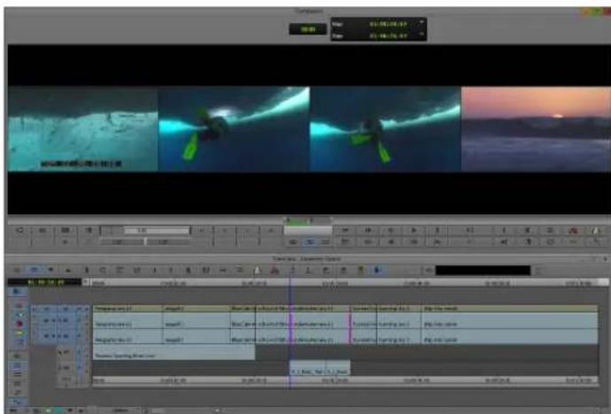
3 Fine-tune edits and effects

4 Fine-tune audio pan, volume, and EQ
5 Screen and continue editing, repeating any or all of steps 1 through 4 as necessary
Outputting a Sequence
When your sequence is finished, you can output it in any of the following ways:
- Export as a file or a series of files.
For more information, see "Exporting Frames, Clips, or Sequences" on page 1005. - Output a digital cut in one or more formats.
For more information, see "Generating Output" on page 1038. - Generate a cut list through Avid FilmScribe ^TM .
- Generate an EDL through Avid EDL Manager.
For more information on FilmScribe or EDL Manager, see the Avid Media Composer, NewsCutter, and Symphony Supporting Applications Guide, or the FilmScribe or EDL Manager Help.

Finished sequence. Output options include:

Export a file

Output to tape

Generate a cut list
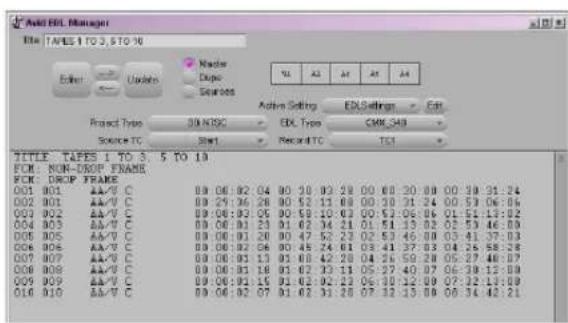
Generate an EDL
2 Starting a Project
Your work begins when you turn on your system, start your Avid editing application, and open an existing project or create a new project. The following topics describe procedures for starting your work, as well as several techniques to safeguard and restore your work if necessary:
• Turning on Your Equipment
• Working with the Desktop
- Starting Your Avid Editing Application (Windows)
• Starting Your Avid Editing Application (Macintosh)
• Working with Projects
- Quitting and Turning Off Equipment
- Avid Projects and Avid Users Folders
- Changing Project and User Names
- Backing Up Your Project Information
- Avid Attic Folder
Turning on Your Equipment
Avid recommends that you turn on your equipment in the following order:
- Storage devices.
- Peripheral devices (such as monitors and speakers).
- Computer system.
- Avid input/output hardware device.

Do not disconnect devices while you run your Avid editing application. Before you start your Avid editing application, make sure you connect all your devices first.
Working with the Desktop
You can use some of the desktop navigation features of your operating system to speed your work or customize for your convenience while you edit. You can:
- Control how the Windows taskbar appears on the screen (Windows only).
- Use the Macintosh Dock as a quick way to launch your Avid editing application (Macintosh only).
- Use shortcut menus (also sometimes known as context menus) to quickly access editing commands.
- Use standard keyboard shortcuts to navigate and select options in dialog boxes and menus.
- Use the mouse scroll wheel for navigation and customize mouse button functions.
You also use the desktop for backups and transferring projects, as described in “Backing Up Your Project Information” on page 64 and “Avid Projects and Avid Users Folders” on page 46.

For information on the Windows desktop and icons, see your Microsoft ^® documentation. For information on the System Folder and the desktop and icons, see your Macintosh documentation.
Using the Windows Taskbar (Windows Only)
By default, the Windows taskbar always appears on the bottom of your screen, on top of your Avid editing application. You have two other choices:
- Keep the taskbar hidden behind your Avid editing application
- Set the taskbar to appear only when you drag the mouse pointer to it
If you keep the taskbar hidden while you run your Avid editing application and you minimize an application such as Help, you do not see the minimized icon in the taskbar.
For more information about the taskbar, see the Windows Help.

You can also drag the taskbar to the top, bottom, or either side of the monitor.
When you work in your Avid editing application, you can minimize windows (such as the Project window and bins). The icons appear in your Avid editing application window, not in the taskbar.
To see the taskbar and minimized icons:
▶Minimize your Avid editing application.
To change the taskbar settings:
-
Right-click an unused part of the taskbar, and select Properties.
The Taskbar and Start Menu Properties dialog box opens. -
Select the options you want:
▶To keep the taskbar hidden, deselect “Keep the task bar on top of other windows” and “Auto hide the task bar.”
To set the taskbar to appear when you want, select “Keep the task bar on top of other windows” and “Auto hide the task bar.”
- Click OK.
Using the Macintosh Dock (Macintosh Only)
You can place an application icon alias on the Dock for easy access to your Avid editing application. The Dock is hidden when your Avid editing application is active. For full information on using the Dock, see the Macintosh documentation.
To display the Dock:
▶ Move the mouse pointer to the edge of the screen where the Dock is hidden.
Using Shortcut Menus
In addition to standard menus to find a command you need, you can use shortcut menus. Shortcut menus show the most frequently used commands for a window or a screen object.
Most shortcut menus contain a What's This? command to access Help for the window or the object.
To use a shortcut menu:
▶Right-click a window or a screen object.
Using the Keyboard for Navigating in Dialog Boxes and Menus
To navigate in dialog boxes and menus and to select and deselect options:
Option Command
To move from tabbed page to tabbed page within a dialog box.
Press Page Up or Page Down.
To move from check box to check box or from option to option in a dialog box.
Press Tab.
Option Command
To select or deselect a check box or an option Press Right Arrow, Left Arrow, or the space bar. in a dialog box.
To move up or down in a menu, or increment a Press Up Arrow or Down Arrow. numeric value.
Using the Mouse Scroll Wheel for Navigating
You can use the mouse scroll wheel to navigate in your Avid editing application, as described in the following table. You can also set the speed to scroll with the mouse wheel, and assign functions to three additional mouse buttons, as described in “Customizing Mouse Functions” on page 37.
| To scroll through items in a window or function area with a vertical scroll bar (such as a bin). | Use the scroll wheel. |
| To move the position bar one frame at a time in the Timeline. | Ctrl (Windows) or Control (Macintosh) + use the scroll wheel. |
| To move the slider one unit at a time in a tool or window containing a slider (such as the Effect Editor). | Use the scroll wheel. |
| To move the slider 10 units at a time in a tool or window containing a slider (such as the Effect Editor). | Press Shift + use the scroll wheel. |
Customizing Mouse Functions
Your Avid editing application lets you set the speed of scrolling with the mouse wheel, and lets you assign functions to three additional mouse buttons.

When you map mouse buttons, make sure that the modifier key that you assign to the button and command does not already have an alternate function.
You cannot assign functions to the standard left and right mouse buttons.
To set the mouse scroll speed:
- In the Project window, click the Settings tab, and then double-click Mouse. The Mouse Settings dialog box opens.

- Select a speed from the Vertical Scroll Speed menu.
Normal is the default setting. Normal scrolls one item at a time. Moderate scrolls two items at a time, and Fast scrolls four items at a time.
To assign functions to additional mouse buttons:
- In the Project window, click the Settings tab, and then double-click Mouse.
The Mouse Settings dialog box opens.
- Select Tools > Command Palette.
The Command palette opens.
-
Select Button to Button Reassignment at the bottom of the Command palette.
-
Click the tab from which you want to select a user-selectable button.
-
Click the mouse, and drag the button from the Command palette to a button location on the Mouse Settings dialog box.
Optimum Performance (Windows 7)
The following list contains suggestions for ensuring optimum performance when working with your Avid editing application on a Windows 7 system:
- It is required to turn off File Sharing. If you do not do this, you might receive Access Denied errors after you move files.
In Control Panel > Network and Sharing Center > File Sharing, select Turn off File Sharing
- Disable CPU throttling.
In Control Panel > Hardware and Sound > Power Options, select High Performance.
- Do not enable the Windows Display setting “Show window contents while dragging.” This setting hinders redraw performance on your Avid editing system.
In Control Panel > Appearance and Personalization > Personalization > Window Color and Appearance > Effects, deselect Show window contents while dragging.
- Enable setting to adjust for best performance.
In Control Panel > System and Maintenance > System > Advanced System Settings > Performance Settings, select Adjust for best performance.
- Disable Desktop compositing.
In Control Panel > System and Maintenance > System > System Protection > Advanced tab > Performance Setting, deselect Enable desktop composition.
- Disable Windows Defender.
In Control Panel > Security > Windows Defender > Tools > Options > Administrator Options, deselect Use Windows Defender > Save.
- Disable Sidebar.
Right-click the Sidebar or Sidebar icon on your desktop > Properties > Deselect Start Sidebar when Windows starts > Right click icon and select Exit.
- Disable Hibernation in the Power options.
In Control Panel > Performance Information and Tools > Power Options > Change when the computer sleeps > Put the computer to sleep, select Never.
- Change Advanced Power Settings.
In Control Panel > Performance Information and Tools > Power Options > Change when the computer sleeps > Change advanced power settings > High Performance (instead of Balanced) Hard disk > Turn off hard disk after Setting: Never.
In Control Panel > Performance Information and Tools > Power Options > Change when the computer sleeps > Change advanced power settings > High Performance (instead of Balanced) Sleep > Sleep after Setting: Never.
- Set automatic updates to Notify you but don't automatically download.
In Control Panel > System and Maintenance > Windows Updates > Change settings, select “Notify me but don’t automatically download them or install them.”
- Turn off the firewall for Avid Interplay.
In Control Panel > Security > Windows Firewall, select Turn Windows Firewall on or off.
- Do not leave the Console window open when you edit. The performance of your Avid editing system slows considerably when the Console window is open.
- Do not leave a Windows Explorer window open. Windows Explorer attempts to update file information.
- Do not leave an e-mail application open if it is set to do periodic checks for mail.
- Do not run any application that periodically “wakes up” and performs an action.
- Disable screen savers.
- Do not keep media on the same partition where you install your Avid editing application. Avid recommends external media drives.
- Always use small fonts with the display driver to avoid missing characters in the dialog boxes in your Avid editing application.
- After you move a drive from one system to another, restart your system. Windows does not recognize the drive until you restart.
- Ensure you do not accidentally delete locked items from your desktop.
Right-click the Recycle Bin icon on your desktop > Properties > General tab > Display delete confirmation dialog.
- When you advance by single frames through the Timeline, deselect Render On-the Fly to enable faster response time.
In your Avid editing application, deselect Clip > Render On-the-Fly
- Do not name files with special characters (/ \ : ? " <> | *). Windows does not recognize special characters in file names. Bin names are limited to 27 characters (not including the four characters reserved for the file name extension).
- Do not schedule automatic backups at times when your Avid editing system might be in use.
- Do not run any application that includes prescheduled or automatically scheduled activities, such as a calendar program.
- Do not leave other applications running. Some applications, such as Microsoft Office, run background processes.
- Do not allow the Find Fast background process (find.exe) to run. The process tries to update its cache of file and folder locations. Check your Startup folder, and delete the file if it is there. To locate the find.exe, select Start > Search > find.exe.
Optimum Performance (Macintosh)
The following list contains suggestions for ensuring optimum performance when working with your Avid editing application on a Macintosh system:
- Do not select the option that puts the hard disk to sleep when possible.
In System Preferences > Hardware Energy Saver, deselect Put the hard disk(s) to sleep when possible. - Set sleep options to Never in Energy Saver preference.
In System Preferences > Hardware Energy Saver, select Never. - Disable screensavers.
In System Preferences > Personal Desktop & Screen Saver > Screen Saver, select Never.
Antivirus Applications
Antivirus programs that contain autoscanning features can interfere with the operation of your Avid editing application. Since virus scanning is a processor-and disk-intensive activity, it can interfere with capturing and playing real-time effects in your Avid editing application.
Avid recommends you do not scan files or schedule any background tasks such as virus scanning when you use your Avid editing application.
File deletion protection utilities also consume system resources and could interfere with the proper operation of your Avid editing application. These utilities automatically back up any files that you delete, even temporary files that you create and delete with your Avid editing application. This consumes a large amount of disk space.
Starting Your Avid Editing Application (Windows)
By default, your Avid editing application is located in the following folder:
drive:\Program Files\Avid\Avid editing application
The installation process adds a desktop icon and a pointer to your Avid editing application in the Start menu.

Your Avid editing application does not start properly if you move the application file from the Avid editing application folder.

If you install your Avid editing application on a laptop computer, a dialog box might open with a message about incompatible power management schemes. Avid recommends you use the “Always On” power scheme for Windows XP and the “High Performance” power option for Windows 7 when you work with Avid editing applications. Other power schemes might affect performance of editing functions (for example, capture and digital cuts).
To start your Avid editing application, do one of the following:
Click Start > All Programs > Avid > Avid editing application.
▶ Double-click the Avid editing application desktop icon.
After your Avid editing application starts, the Select Project dialog box opens. For more information on the Select Project dialog box, see “Working with Projects” on page 42.
Starting Your Avid Editing Application (Macintosh)
Your Avid editing application is in the following location:
Macintosh HD/Applications/Avid editing application
For most users, the desktop or Dock is a more convenient location to start your Avid editing application. The installation process places a shortcut alias icon for your Avid editing application on the desktop.

For more information to make an alias and use the Dock, see your Macintosh documentation.

Your Avid editing application does not start properly if you move the application file from the Avid editing application folder. You can drag it onto the Dock, and an alias appears on the Dock.

When you start your Avid editing application, you might see a message box which indicates there is no input or output signal. Check to ensure that your Avid input/output hardware is connected to the system with the cables secured and that it is turned on.
To start your Avid editing application, do one of the following:
▶ Double-click the alias icon for your Avid editing application on the desktop.
▶ Double-click the alias icon for your Avid editing application on the Dock.
▶ Select Go > Applications, and then double-click the Avid editing application folder. Then double-click the Avid editing application file.
You might see a license agreement. After your Avid editing application starts, the Select Project dialog box opens. For more information on the Select Project dialog box, see “Working with Projects” on page 42.
Working with Projects
When you start the editing application, the system displays the project log in window. Amongst other settings, you can determine the location of the project. Media Composer allows you work with projects in a private location or one that can be shared with other users.
The best choices for a shared structure are either Shared or External. These types of projects are created in a common location, making it easier for the Administrator to locate and delete old projects.
If you work in an Interplay environment, you can also share a synced project. For more information, see “Interplay Synced Projects” on page 1203.

If you will be working in a shared project environment, you should carefully consider the location of your projects and media. This will make for a much more efficient working environment in terms of time and disk storage space.
If you are working with projects created on local drives, then note the following:
- A local project resides on the C: drive of the Avid editing system.
- If the connection between the Avid editing system and shared storage is lost, the project and its contents are unlikely to become corrupt as a by-product.
- You cannot login to the project from another workstation. The exception is if you are in an Interplay environment. In this case, you (or other users) must go to the Interplay Projects folder to locate the contents created in this project.
- From an administration standpoint, you must clean these projects up or archive them from each editing system. At a large site this can become time consuming and needs to become part of the Administrator's workflow.
For information on the files and folders that your Avid editing application creates as part of a project, see “Avid Projects and Avid Users Folders” on page 46.
You should also back up your project information regularly to a separate storage device, as described in “Backing Up Your Project Information” on page 64.
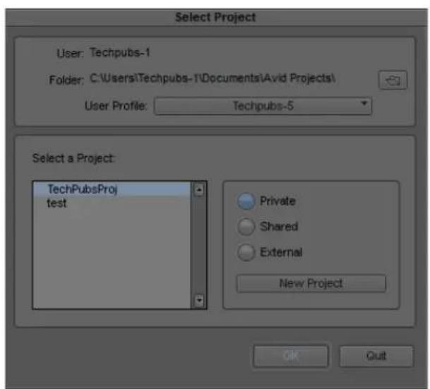
Private
A Private Project is stored locally. It can be accessed only by the user currently logged on to the editing machine. On a Windows system, a Private Project is always stored under the user's Documents directory. An administrator may be able to access this project if they have read/write permission to the user's directory.

Shared
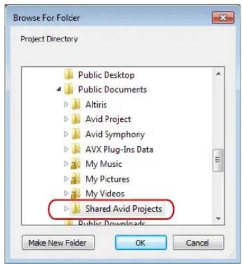
A Shared Project is stored locally. It can be accessed by any user that can log on the editing machine. On a Windows system, a Shared Project is always stored in the machine's Shared Documents directory.

External
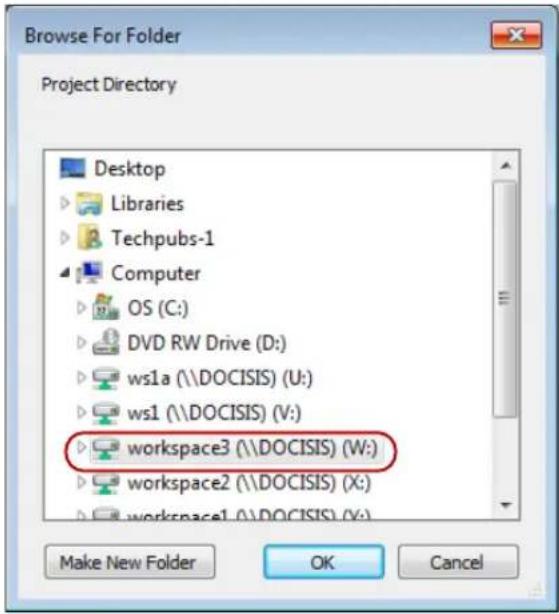
An External Project can be saved to any directory, either local or remote. Depending on the file-system permissions set on the selected folder, other users or an administrator may or may not be able to access the project. The external option is particularly useful when you want to save the project on shared network drive to make project maintenance easier.

Avid does not support sharing bins in an Interplay environment. If you create projects on shared storage, do not allow editors to work in the same bin at the same time. This can result in data loss or media corruption. Instead of sharing bins, editors should use the Interplay Window to collaborate and share material.

Synced
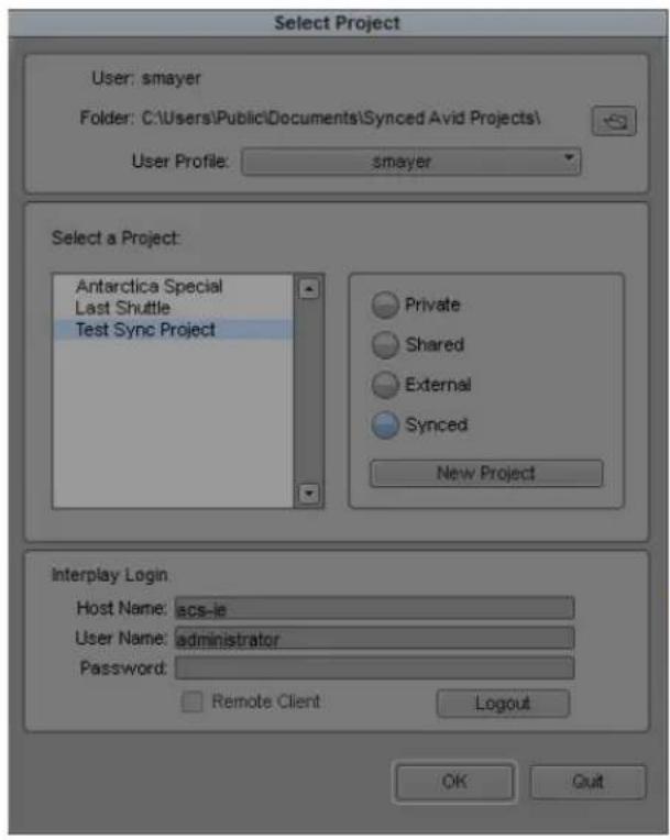
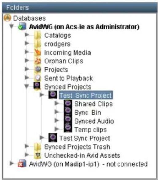
A Synced Project is stored locally and in your Interplay database. It can be accessed by any user who has permissions for the project. On a Windows system, a Synced Project is always stored in the machine's Shared Documents directory and in a corresponding project folder on Interplay.
Avid Projects and Avid Users Folders
When you create a new project or user profile, your Avid editing application creates files and folders in the Avid Projects and the Avid Users folders.
Locations of Avid Project Folders
By default, the system installs two Avid Projects folders:
| Private Shared | |
| Windows drive:\Documents and Settings\Windows login name\Documents\Avid Projects | drive:\Documents and Settings\All Users\Shared Documents\Shared Avid Projects |
| Macintosh Macintosh HD/Users/Mac login name/Documents/Avid Projects | Macintosh HD/Users/Shared/Avid editing application/Shared Avid Projects |
Locations of Avid Users Folders
The Avid Users folder is located in the application folder:
Windows 7 drive:\Documents and Settings\All Users\Shared Documents\Avid editing application\Avid Users
Macintosh Macintosh HD/Users/Shared/Avid editing application/Avid Users

(Windows only) The location of the Avid Users folder depends on the installation path for your Avid editing application.
Files and Folders Created For Projects
When you create a new project, your Avid editing application creates a folder with the name that you entered when you created the project. The following three files are stored within the project folder:
- A project file (.avp)
• A project settings file (.xml) - A bin file (.avb)
The project folder and the three files all use the project name you provide. The project folder is stored in the Avid Projects folder.
Your project settings are initially set to the default values. As you create additional bins for the project (see “Creating a New Bin” on page 73), additional bin (.avb) files are added to the project folder.
Files and Folders Created For User Profiles
When you create a new user profile, your Avid editing application creates a folder for the user and two files that are stored within the user folder:
• A user profile file (.ave)
- A user settings file (.xml)
The user folder and the two files all use the user profile name you provide. The new folder is stored in the Avid Users folder.
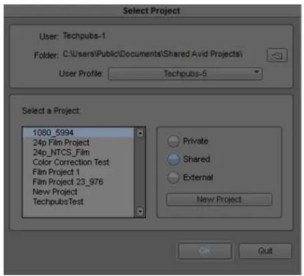
Select Project Dialog Box
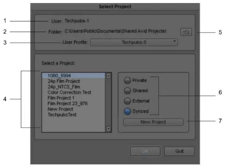
The Select Project dialog box lets you find and open a project, create a new project, or establish user profiles.
Element Description
1 User Displays the login name of the user currently logged into the system. To change to a different user, log out and log in as that user.
2 Folder Displays the path of the current folder. This path determines which projects appear in the project list and where a new project is created.

You cannot type into the User or Folder text boxes.
Element Description (Continued)
3 User Profile Displays the name associated with the current settings. By default your Avid editing application uses the login name. The list button changes profiles or creates a new one. For more information, see “Understanding User Profiles” on page 87.
4 Project list Displays a list of the Avid projects in the currently selected folder. Double-click a project to open it.
5 Browse button Lets you navigate to a different folder. The projects in this folder appear in the project list. See “Opening and Closing Projects” on page 58.
6 Folder buttons The button you select will set the location where you can browse or create projects.
Private: Local folder for the user currently logged in.
Shared: Local folder that is visible to all users that have accounts on this system.
External: Local or remote folder that any other users may have access to depending on the file permissions set on this folder.
Synced: (Interplay only) Local and Interplay folder that other users may have access to depending on permissions.
For more information, see “Working with Projects” on page 42.
7 New Project button Opens the New Project dialog box to create a new project.
Project Types
The following table lists the format options available for your project. Depending on the model of your Avid editing application, your format options might not include all items listed here.
Project Type Source Footage Transfer Color Space
23.976p NTSC For film-originated or video-originated footage that has been shot at 23.976 fps or film-originated footage transferred on digital videotape (such as Digital Betacam ^™ ) YCbCr
24p NTSC For film-originated or other 24-fps footage transferred to NTSC videotape YCbCr
24p PAL For film-originated or other 24-fps footage transferred to PAL videotape YCbCr at 25 fps
25i PAL For PAL video-originated footage (25 fps) YCbCr
25p PAL For 25-fps film footage transferred to PAL videotape YCbCr
30i NTSC For NTSC video-originated or other 30-fps footage transferred to NTSC YCbCr videotape
Project Type Source Footage Transfer (Continued) Color Space
| 720p/23.976 For film-originated material transferred to videotape. YCbCr | |
| 720p/25 For video-originated material that can be captured, edited and output for HD broadcast. It can also be captured in DVCProHD format. | YCbCr |
| 720p/29.97 For video-originated material. Can be directly captured, edited, and output for HD broadcast. | YCbCr |
| 720p/50 For HDV broadcast (European broadcast). YCbCr | |
| 720p/59.94 For video-originated material. Can be directly captured, edited, and output for HD broadcast. | YCbCr |
| 1080p/23.976 For film footage transferred to videotape, or high-resolution files from digital film cameras. | YCbCrRGB |
| 1080p/24 For film footage transferred to videotape, or high-resolution files from digital film cameras. True 24-fps editing. | YCbCrRGB |
| 1080p/25 For film footage transferred to videotape, or high-resolution files from digital film cameras. | YCbCrRGB |
| 1080p/29.97 For film footage transferred to videotape, or high-resolution files from digital film cameras. | YCbCrRGB |
| 1080i/50 For video-originated material, or high-resolution files from digital film cameras. Can be directly captured, edited, and output for HD broadcast. | YCbCrRGB |
| 1080i/59.94 For video-originated material, or high-resolution files from digital film cameras. Can be directly captured, edited, and output for HD broadcast. | YCbCrRGB |

Some older versions of Avid editing applications provided HD project types based on HDV requirements. In current versions of Avid editing applications, these are replaced by standard HD projects that let you specify the raster dimensions for editing and playback.

Set film preferences in the Film and 24P Settings dialog box immediately after you create a project to provide your Avid editing application with important information about the type of film and audio transfer you used for your project.
Creating a New Project
You can create a project in any format. The settings you choose for your project will dictate the way in which your material is handled for the various editing functions within the Avid application.
The project format describes the frame size, aspect ratio, frame rate, and the color space for all sequences created within the project. You should set your project format according to the quality required for the final delivery.
Read the following topics before setting your project format:
- Setting the Project Format to Accommodate Variable Resolutions
- Setting the Project Color Space
To create a new project:
- In the Select Project dialog box, select the folder in which you want to create the project: Private, Shared, External, or Synced — see Working with Projects.

You must be logged in to Interplay to create a Synced Project. For more information on synced projects, see “Interplay Synced Projects” on page 1203.
- Click New Project.
The New Project dialog box opens.
- Type the name of your new project in the text box.
- Click the Format menu and select a project format that matches your media and delivery requirements.
The rest of the options might change depending on the project format you choose.
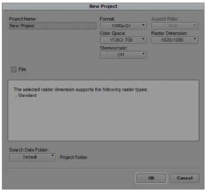
Example of the New Project dialog box
- Set the following option(s), where applicable:
| Option SD HD | |||
| Project Format | A combination of the video format (e.g. NTSC, PAL, HD), the video mode (e.g. 1080p, 720p) and the frame rate (e.g. 23.97, 24, 25 fps). Choose the most appropriate combination for your output format. | ||
| Aspect Ratio | The numerical ratio of the picture width to height. Set the aspect ratio for standard (SD) video and television at 4:3, and at 16:9 for HD.The project uses the aspect ratio setting to determine the display setting in the monitors, and as a factor in determining whether material requires resizing or repositioning in sequences. For more information, “Mixing Frame Sizes and Aspect Ratios” on page 596. | Select either 4:3 or 16:9 | Always uses the 16:9 aspect ratio. |
| Raster Dimension | Set the spatial resolution at which your clips will be processed on the timeline. The resolution is the number of pixel columns (width) by the number of pixel rows (height), for example 1920 by 1080. Some devices create media in non-standard resolutions--for example, HDV (1440 x 1080).Note: These non-standard dimensions are only available if there is an Avid codec to support it.The Raster Dimension menu appears only for HD projects on a supported system. For more information, | Always uses YCC | YCC 709 or RGB 709 |
| Color Space Set the color coordinate system to be used for interpreting color values in your media and transforming them to the selected color space for the editing application.[Tyr8] When using source material that is full frame, the frame compatible format is generated on the fly which may result in a performance slowdown. | Always uses YCC | N/A | |
| Film Available for 23.976p, 24p, 25p, 720p, and 1080p film projects. Click the Film button and select a format for film gauge tracking from the Default Film Type menu. | N/A | ||
| Audio Transfer Rate | Available for 24p PAL projects. N/A | ||
Option SD HD
Matchback Available for 25i PAL, 30i NTSC, 720p, and 1080i Matchback projects only. Select Matchback, then click the Film button and select a format for film gauge tracking from the Default Film Type menu.

The Matchback item appears only if your Avid editing application includes the Matchback option.
SearchData Specifies the location for the folder to be used by Folder PhraseFind. By default, this is set in the Projects folder. This folder keeps an index of text or phonetic searches.
- Click OK.
Your Avid editing application creates the new project files and folder, and then returns to the Select Project dialog box. The project name is highlighted in the Projects list.
- Double-click the project name to open the project.
The Project window, the Composer window, and the Timeline open with your User settings loaded.
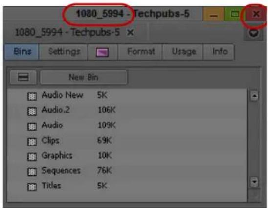
Project name and user name in the title bar (left) and Close button (right) in the Project window
- (Option) If your project uses a film project type, set film preferences immediately after you create the project.
Setting the Project Format to Accommodate Variable Resolutions
Regardless of the project output format, you can still work with media of different frame sizes, aspect ratios, and pixel aspect ratios in the same sequence. For example, you can mix SD 4:3, HD 16:9, and 2K+ media formats. Your Avid editing application automatically resizes and repositions these clips to match the project's format settings.

The original media size, resolution and color properties are preserved in the metadata of the clip in case the sequence needs to be conformed in other applications.
If you intend to output in multiple formats, e.g. broadcast in NTSC, PAL, and HD, then you can edit your project format in the highest format which in this case would be HD. After outputting to HD, you can then switch the project format to NTSC, and reformat and re-render any necessary titles/effects before output. (See Mixing Frame Sizes and Aspect Ratios; Mixing Frame Rates and Field Motion Types in the online help.)
Working with Color Spaces in HD Projects
In full HD projects, some Avid editing applications and Avid input/output hardware devices let you work in either the YCbCr or the RGB color space. Your Avid editing application uses a project's color space setting to control how it displays video, processes most effects, and outputs sequences.
RGB and YCbCr both separate colors into three channels, but they store color information differently. When you choose which color space to work in, you need to take several factors into consideration, including the color space of your media, your output needs, and your performance expectations for your Avid editing application while editing.
The RGB color space is not available for 720p or NTSC/PAL SD projects.
Understanding the YCbCr Color Space
YCbCr performs better, but is of lesser quality.
YCbCr stores brightness (Y) separately from colors (Cb and Cr). Since humans are more susceptible to changes in light than in color, YCbCr discards half the chrominance data (one-third of the overall data) with little discernible difference to image quality. Media that uses YCbCr takes up less disk space than media that uses RGB, and less bandwidth is required to play it.
YCbCr is the only color space available for SD media, because SD requires lower bandwidths and might need to maintain backwards compatibility with black-and-white displays. When you only need SD output, you only need to work in the YCbCr color space.
Newer HD technologies can display detailed images with sharp changes in color. Because some color data is missing, YCbCr media does not take full advantage of HD display hardware. The limited color information available in YCbCr also means that the results of effects processing are not as good as they could be with RGB media.
Understanding the RGB Color Space
RGB produces higher quality images and effects, but takes up more space.
RGB separates images into their constituting colors: red (R), green (G), and blue (B) and does not discard any of the chrominance data. As a result, video images look sharper, particularly those with fast motion or abrupt changes in color. Newer HD formats support RGB only.
Because no color data is lost, your Avid editing application can make more precise calculations when processing effects using RGB media. The quality improvement over YCbCr processing is most noticeable in effects that perform color analysis, such as chroma keyers. Even if the original video data is in YCbCr, your should consider converting to RGB to process effects as precisely as possible.
The disadvantage of RGB is file size. Media that uses RGB takes up more disk space than media that uses YCbCr, and more bandwidth is required to play it. Some systems might not be able to handle playback of RGB material smoothly, particularly when you use the J-K-L keys to play at greater than normal speed or to play in reverse.

RGB media requires high bandwidth. For effective playback of multiple streams of video at higher resolutions, you should distribute the video tracks as evenly as possible among available drives, and target separate drives for audio and video.
Choosing a Color Space for Your Project
Your choice of a color space depends on both your input/output hardware and your desired output. For information on how to define the color space for a project, see “Changing the Project Color Space for an HD Project” on page 57.
If your hardware supports both RGB and YCbCr, choose the color space that corresponds to your output needs.
If your hardware supports only YCbCr, you can choose RGB for your project color space to maintain maximum quality throughout your workflow. Your Avid editing application converts your material to YCbCr right before sending it to the hardware for monitoring or output.
The project color space specifies how your Avid editing application processes effects in real time. Your Avid editing application supports native processing of effects in either the RGB or YCbCr color spaces. For example, this means that RGB media does not need to be converted to YCbCr for processing, maintaining maximum video quality until the final output.
Mixing Media of Different Color Spaces
You can work with media of different color spaces in the same sequence. For example, you can mix SD YCbCr and HD RGB. When you mix media in this way, your video editing application converts media to the project's color space when necessary. This conversion takes place internally during the processing of real-time effects and prior to output.
The color space of your media depends on its format. Tape-based SD and HD media uses the YCbCr color space. Newer HD digital formats, such as R3D, use RGB. See “Resolution Specifications” on page 1470 for information about supported formats.
You can check the color space of the media for any clip in your project by viewing the Color Space bin heading in the bin that contains the clip. For more information, see “Moving, Aligning, and Deleting Bin Columns” on page 346.
Setting the Project Color Space
When assembling a project, it is very common to have media originating from different sources. These can include SD or HD tapes, file-based cameras, film frames scanned to files, and even computer-generated graphics. Each of these media sources can have arbitrary color encoding (i.e. color model, gamma, bit depth, etc.). The editor needs to see each of these media sources with their true colors from the beginning to the end of the editing process.
When a project is created, a common color space needs to be selected for the processing of all media within a sequence. This color space maintains a consistent color appearance when color values from different media sources are sent to a particular device (either a monitor, storage, or output).
The working color space should be set according to the delivery requirements. As an example, for broadcast HD TV, set it to Rec. 709. For a sequence that will be delivered in multiple formats, the working color space should be set to the highest overall precision and range.
Color Space is the predefined limit for the range of colors that can be represented in a given file, application or device. When images are processed, the color that they were encoded with by the camera is transformed to the color space of the Media Composer application. This is known as color mapping.
When these same images need to be viewed on a monitor, the colors need to be mapped to the color space of the monitor. (The color space of the monitor is not set within Media Composer. It needs to be calibrated separately as per the vendor's instructions).
Changing the Project Color Space for an HD Project
The Color Space setting determines the color coordinate system to be used for interpreting color values in your media and transforming them to the selected color space for the editing application. The RGB color space is only available in full HD projects. 720p and NTSC/PAL projects can only use the YCbCr color space.
The project color space can be changed at any time. All color transformations are applied on the media during playback.
Changing the project color space does not affect the rendering of titles and effects or change the color space of imported media. Your Avid editing application controls these according to their Media Creation Settings. For more information, see “Media Creation Settings” on page 1424.
To change the project color space:
-
Click the Format tab in the Project window.
-
Click the Color Space menu, and select either RGB 709 or YCbCr 709, depending on the color space you want to use.

Color Space menu in the Format tab of the Project window
Your Avid editing application now displays video and processes real-time effects in the new color space. The final output is also in the new space.
Setting Project-Naming Conventions
The system limits bins and project names to 27 characters, not including the period and 3-character extension that the system automatically adds to a file name. If you plan to move bins and projects from one platform to another, do not use the characters / \ : * ? "< > | or leading spaces, trailing spaces, or trailing periods, when you name a project, bin, and user.
(Macintosh only) If you use your Avid editing application as a standalone editor (and don't plan to move your bins or projects to another platform), you can extend bin and project names to 31 characters. You can also choose to accept or not accept the Windows compatible file naming convention of special characters and spacing.
To use Windows compatible file names
- Click the Settings tab in the Project window.
The Settings list appears. - Double-click General Settings.
- Select Use Windows compatible file names.
This prevents your Avid editing application from accepting the restricted characters in a bin, project, or user name.
To extend project and bin names to 31 characters (Macintosh only)
- Click the Settings tab in the Project window.
The Settings list appears. - Double-click General Settings.
- Select Allow files names to extend 27 characters.
This extends the names of projects and bins to 31 characters.
Opening and Closing Projects
You can open a project from the Select Project dialog box, and navigate from the Select Project dialog box to find any project on your system.
If you have already created a project, when you enter your Avid editing application you can bypass the Select Project dialog box and have your last project open automatically.
If you choose to install the sample startup project and media when you install your Avid editing application, you can open this project from the Select Project dialog box. The startup project, called Avid Boston Project DV25, contains a complete sequence with rendered effects and titles, as well as all the video and audio clips used in the sequence.
Use the startup project to learn how to edit with your Avid editing application, before you capture any media of your own. You can explore the sequence in the Timeline to learn how it is assembled, and use the clips to practice viewing and editing techniques described in this guide.

If a sequence that was created in an older version of an Avid editing application contains effects or color corrections, you might need to update the sequence. If a sequence requires updating, the Update Sequence dialog box might open when you load the sequence. For more information, see “Updating and Reverting Existing Effects in Sequences” in the Help.
To open an existing project:
- In the Select Project dialog box, select the folder in which the project is located: Private, Shared, or External.
For more information, see “Select Project Dialog Box” on page 48.
- Do one of the following:
▶Select a project in the Select Project dialog box, and then click OK.
▶Double-click a project name in the Projects list.
The Project window, the Composer window, and the Timeline open with the User settings loaded. The title bar of the Project window contains the project name and the user profile selected in the Select Project dialog box.
To browse for a project in a location other than the default Shared and Private folders:
- Start your Avid editing application.
The Select Project dialog box opens.

Browse button in the Select Project dialog box
- Click the Browse button.
The Browse for Folder (Windows) or Project Directory (Macintosh) dialog box opens.
- Navigate to the folder that contains the project you want.
- Click OK (Windows) or Choose (Macintosh).
- Select a project in the Projects list.
- Click OK.
The Project window, the Composer window, and the Timeline open with the User settings loaded. The title bar of the Project window contains the project name and the user profile selected in the Select Project dialog box.
The next time you open the Select Project dialog box, the path you selected will be displayed when you click the External button.
To open a project automatically:
- Click the Settings tab in the Project window.
The Settings list appears.
- Double-click any Interface setting.
The Interface Settings dialog box opens.
- Click the General tab, select "Automatically Launch Last Project at Startup," and then click OK.

The next time you start your Avid editing application, it opens your last project.
To turn off the automatic opening of projects so that you can select another project when you start your Avid editing application:
- Deselect "Automatically Launch Last Project at Startup," and then click OK.
- Quit your Avid editing application and restart it.
The Select Project dialog box opens.
- Select a project and click OK.
The Project window, the Composer window, and the Timeline open with the User settings loaded.
To open the startup project:
- In the Select Project dialog box, click the Shared folder button.
- Double-click Avid Boston Project DV25 in the Project list.
The Avid Boston Project DV25 project opens.

The footage in the Avid Boston Project DV25 project is shot in 16:9 aspect ratio. To view the footage correctly in monitors, click the Format tab in the Project Window and set aspect ratio to 16:9.
- In the Format tab of the Project window, ensure that Aspect Ratio is set to 16:9.
The footage in the Avid Boston Project DV25 project is shot in 16:9 aspect ratio.
-
Use the Bins tab in the Project window to open one or both of the bins in the project:
-
Boston Seq DV25 contains a complete sequence
- Boston Project source contains all the video and audio clips in the project
For more information on opening bins, see “Opening and Closing Bins” on page 74.
To close the current project, do one of the following:
▶With the Project window active, select File > Close Project.
▶Click the Close button in the Project window.
Deleting a Project
To delete a project:
- Start your Avid editing application.
The Select Project dialog box opens. -
Click the project you want to delete.
-
Press the Delete key.
- If you see a message asking if you want to delete the selected project and associated bins, click OK
The deleted project no longer appears in the Select Project dialog box.

Deleting a project also deletes any bins that are in that project.
Media related to a deleted project is not deleted with the project folder. For more information on deleting media files, see “Deleting Items from a Bin” on page 337 and “Deleting Media Files with the Media Tool” on page 447.
Quitting and Turning Off Equipment
If you work in an Avid Unity ^™ environment, your Avid editing application writes a media database file (.mdb) to the workspace where you work. Before you quit your Avid editing application, make sure that the workspace has approximately 50 MB of storage space available. Ask your Avid Unity administrator to increase the space if you need more storage.
To quit your Avid editing application and leave it immediately:
(Macintosh) Select Avid editing application > Quit Avid editing application.
▶(Windows) Select File > Exit.
The project closes and your Avid editing application quits.
To quit your Avid editing application and view the Select Project dialog box:
- Click the Close button at the far right (Windows) or at the far left (Macintosh) of the Project window's title bar.
The Select Project dialog box opens.
- Click Quit.
A message box opens.
- Do one of the following:
▶Click Leave to quit your Avid editing application.
▶ Click Cancel to return to the Select Project dialog box and select another project.
To view remaining storage on your media drives:
- Click the Info tab in the Project window, and then click Hardware.
The Hardware tool opens.
- Click the appropriate drive tab.
For more information, see “Using the Hardware Tool” on page 116.

Quit your Avid editing application before you turn off your equipment.
To turn off your equipment:
- Turn off the system by doing the following:
For a Windows system:
a. Click the Start button, and select Shut Down. The Shut Down Windows dialog box opens.
b. Click the menu, and select Shut down.
c. Click OK.
For a Macintosh system:
▶Select Apple menu > Shut Down.
- If you have an Avid input/output device attached to your system, turn it off.
- Turn off peripheral devices (such as monitors and speakers).
- Turn off external storage devices.

Never remove media drives from your Avid system when it is turned on. Shut down the computer, and then remove the drives.
- Turn off all other hardware.
Changing Project and User Names
You cannot change project or user names from within your Avid editing application. You must change the names from your desktop before you start your Avid editing application. For information about the location of the Avid Projects and Avid Users folders, see “Avid Projects and Avid Users Folders” on page 46.

When you change a user name or a project name, make sure you change the name of the folder and all the files in the folder that have the old name. Your Avid editing application does not automatically change the names of corresponding files in the folder.
To change a project name or user name:
- Navigate to the Avid Projects or Avid Users folder, and then double-click the folder to open it.
-
Click the name of the folder you want to change.
The name highlights. -
Type the new name of the folder.
- Double-click the folder with the new name to open it.
The folder contains profile, settings, and project files with the old name.
- Change the old name of each file to the new name.

Do not change the name of the file MCState in the Avid Users folder.
- Close the windows, and restart your Avid editing application.
The new project name or user name appears in the Select Project dialog box.
Backing Up Your Project Information
Although your Avid editing application automatically saves your bins, projects, and settings, you should back up these items frequently. Because the storage requirements are minimal, you can back up these files to a variety of storage devices, such as:
• U S B ( t h u m b ) d r i v e
- CD-ROM or DVD-ROM
• Network storage device (such as a file server)
- Mass-storage device

To back up the larger media files created when you capture footage, use a high-capacity storage device. For information on backing up media files, see “Backing Up Media Files” on page 466.
To save your work on a drive or on removable media:
- Mount the drive or insert the storage media (USB drive, CD-ROM, or DVD-ROM).
- (Windows only) From the Windows desktop, double-click the My Computer icon.
- Double-click the icon for the destination storage drive or storage media to open it. Double-click any additional folders to target the appropriate storage location.
- Navigate to the folder that contains the project folder or the user folder you want to save.
- Drag a project folder or a user folder to the targeted storage location.
- When the system finishes copying the files, unmount the drive or eject the media and store it.
To restore a project or user information from a backup storage device:
- Mount the drive or insert the removable media that contains the backup copies you want to restore.
-
From the desktop, double-click the icons for the drive or storage media and for the internal hard drive (Windows) or for the Macintosh HD (Macintosh).
-
Drag the copies from the storage device to the appropriate folder on the internal hard drive (Windows) or Macintosh HD/Users/Shared (Macintosh).
When you start your Avid editing application, the restored project and user profile appear in the Select Project dialog box.

If you restore a single bin or bins, you must relink them to the project from within the Project window. For more information, see “Opening and Closing Bins” on page 74.
Avid Attic Folder
The Avid Attic folder contains backup files of each bin in a project. You retrieve files from the Avid Attic folder in the following circumstances:
- When you want to replace current changes to a sequence or clip with a previous version
- When the current bin file becomes corrupted
For information on retrieving files from the Avid Attic folder, see “Retrieving Files from the Avid Attic Folder (Windows)” on page 66 and “Retrieving Files from the Avid Attic Folder (Macintosh)” on page 68.
For information on setting automatic save features, see “Saving Bins” on page 77.

(Macintosh only) If you deselected the “Allow filenames to exceed 27 characters” option in the General Settings dialog box, you cannot retrieve a backup file with a file name larger than the 27-character limit. You must rename the file before you retrieve it.
The Avid Attic folder contains a folder for each project. Each project folder contains a Bins folder. When a bin is saved, a folder with the bin's name is created in the Bins folder and a copy of the bin file is stored in the folder with the bin name. The system adds the file name extension .bak plus a version number to the bin's file name. The bin file with the highest version number represents the latest copy of the bin file.
When you view a bin folder in Details view (Windows) or List view (Macintosh), you can also identify the most recent backup file based on the timestamp of creation displayed in the Modified column (Windows) or Date Modified column (Macintosh).

The oldest backup file is overwritten only if the second-oldest backup file is more than 2 hours old.
Retrieving Files from the Avid Attic Folder (Windows)
To retrieve a file from the Avid Attic folder:
- Minimize your Avid editing application.
- From the desktop, double-click the Avid Attic folder, located in:
(Windows XP) drive:\Documents and Settings\All Users\Shared Documents\Avid editing application.
(Windows Vista or Windows 7) drive: /Users/Public/Public Documents/Avid editing application.
The Avid Attic folder opens and displays a folder for each project.
- Double-click a project folder, and then double-click the Bins folder.
The Bins folder opens and displays a folder for each bin in the project. - Double-click the folder for the bin you want to retrieve.
- If the bin folder is not already in the Details view, select View > Details.
The bin folder displays the backup bin files and their creation dates. A backup bin file has the same name as the bin, with a number appended. For example, a bin named Source Clips might have backup bin files named Source Clips.1 and Source Clips.2.

-
Select the backup bin file or files you want to retrieve.
-
Ctrl+drag the selected backup bin files to the desktop.
This makes a copy of the files, leaving the original files in the Avid Attic folder.
To copy backup files to a new bin:
- Click the taskbar item for your Avid editing application to restore it.

If the taskbar is hidden, see "Using the Windows Taskbar (Windows Only)" on page 35.
- Click the Project window to activate it, and click the Bins tab to display the Bins list.
- Select File > Open Bin.
- From the Files of Type list, select All Files (*.*)
- Navigate to the desktop, select one of the backup bin files you copied, and click Open.
The backup bin opens. When you open a backup bin, a link to the backup bin on the desktop is created in the Other Bins folder.

Your Avid editing application does not allow a bin and a copy of a bin to be open at the same time. You must keep all other bins closed and open the backup bins one at a time.
- Create a new bin.
For example, if you are retrieving clips from a backup bin called Audio.2, you can call the new bin Audio New.

- Select the material you want to keep from the backup bin, and drag the files to the new bin.
- Repeat steps 3 through 7 for any other backup bin files you copied to the desktop.
- Select and delete the backup bins in the Other Bins folder.
- Drag the backup bin files on the desktop to the Recycle Bin.
Retrieving Files from the Avid Attic Folder (Macintosh)
To retrieve a file from the Avid Attic folder:
- Minimize your Avid editing application.
- From the desktop, double-click the Macintosh HD/Users/Shared/Avid editing application/Avid Attic folder.
The Avid Attic folder opens and displays a folder for each project. - Double-click a project folder, and then double-click the Bins folder.
The Bins folder opens and displays a folder for each bin in the project. -
Double-click the folder for the bin you want to retrieve.
-
Select View > as List, if the bin folder is not already in the List view.
The bin folder displays the backup bin files and their creation dates. A backup bin file has the same name as the bin, with a number appended. For example, a bin named Source Clips might have backup bin files named Source Clips.1 and Source Clips.2.
- Command+click the files you want to retrieve.
- Option+drag the selected backup bin files to the desktop.
This makes a copy of the files, leaving the original files in the Avid Attic folder.
To copy backup files to a new bin:
- Click the icon for your Avid editing application on the Dock to activate your Avid editing application.
- Click the Project window to activate it, and click Bins to display the Bins list.
- Select File > Open Bin.
- Navigate to the desktop, select one of the backup bin files you copied, and click Open.
The backup bin opens. When you open a backup bin, a link to the backup bin on the desktop is created in the Other Bins folder.

Your Avid editing application does not allow a bin and copy of a bin to be open at the same time. You must keep all other bins closed and open the backup bins one at a time.
- Create a new bin.
For example, if you are retrieving clips from a backup bin called Source Clips.2, you can call the new bin Source Clips New.
-
Open the new bin and open the backup bin in the Other Bins folder.
-
Select the material you want to keep from the backup bin, and drag the files to the new bin.
-
Repeat steps 3 through 7 for any other backup bin files you copied to the desktop.
-
Select and delete the backup bins in the Other Bins folder.
-
Drag the backup bin files on the desktop to the Trash.
3 Working with the Project Window
The Project window provides controls for structuring and viewing important information about your current project. You can also modify User, Project, and Site settings from the Project window and display a list of effects.
The following topics describe features of the Project window:
• Overview of the Project Window
- Controlling Project Window Display
- Using the Bins Tab
• Using the Settings Tab
• Using the Format Tab
• Using the Usage Tab
• Using the Info Tab
- Managing Bins and Memory
• Understanding User Profiles
- Managing User Profiles
- Customizing the Avid User Interface
- Using Workspaces
• Working with Bins and Projects in an Avid Shared Storage Environment
• Working with Export Volumes
Overview of the Project Window
The Project window is a central location for important information and tools that you need as you work on your project.

Project window information is organized in tabs.
Tab Function
| Bins | Lets you create and open bins. See “Using the Bins Tab” on page 72. |
| Volume | Lets you create an Export Volume. See “Working with Export Volumes” on page 430. |
| Settings | Lets you view and modify settings. See “Using the Settings Tab” on page 78. |
| Effects | Lets you access a library of effects. See “Applying Effects” in the Help. |
| Format | Lets you view information about the format of the project. See “Using the Format Tab” on page 79. |
| Usage | Lets you view information about the work session usage. |
| Info | Lets you view information about system memory usage and system hardware configuration. |
Controlling Project Window Display
The Project window opens automatically when you select a project. You can use the Project window's tab to change the display of information in the window.
The Project window is always open when you are working in a project. However, it might become hidden behind open bins or tools.
To change the information display in the Project window:
▶Click one of the tabs.
To locate and redisplay the Project window, do one of the following:
▶Select Tools > Project.
▶Click in an area of the Project window to bring it forward.
To close the Project window, do one of the following:
▶With the Project window active, select File > Close Project.
▶Click the Close button in the Project window.
The Select Project dialog box opens.
Using the Bins Tab
When you create a project, your Avid editing application automatically creates a bin with the name of the new project, which displays in the Bins tab. You can rename this bin and create additional bins as you work in your project.
The word bin is a movie industry term that refers to a container that holds pieces of film. In your Avid editing application, bins contain master clips that are created when you capture source material. Bins also contain the sequences, subclips, group clips, and effect clips that you create during a project. From the Project window, you can view a list of bins associated with the project, and open, close, and create bins. You can also open bins that you create for other projects.
Viewing a List of Bins
You can view a list of bins in the Project window. The Bins list displays the number, names, sizes, and location of the bins. Bins from other projects appear in the Project window in italic.
To view a list of bins associated with the project:
▶Click the Bins tab in the Project window.

Fast menu button (top) and Bins list with bin icons (bottom) in the Bins tab of the Project window.
Creating a New Bin
To create a new bin from the Project window:
- Do one of the following:
▶Select File > New Bin.
▶Click the New Bin button in the Project window.
A new (empty) bin opens and is given the name of the project as displayed in the title bar of the Project window. The new bin appears in the Bins list in the Project window with a default name highlighted and a number appended to it.
- In the Project window, click the new bin name and type in a new name.
- Press Enter (Windows) or Return (Macintosh).
A corresponding bin file is placed in the Avid Projects folder, and a backup copy is placed in the Avid Attic folder. For more information, see “Avid Projects and Avid Users Folders” on page 46 and “Avid Attic Folder” on page 65.
To place a bin in a folder:
▶Drag the bin to the folder icon.
Renaming a Bin
Each new bin that you create takes the name of the project that appears in the title bar of the Project window and is numbered incrementally.

If you plan to move bins and projects from one platform to another, do not use the characters / \ : * ? “ < > | or leading spaces, trailing spaces, or trailing periods, when you name a project, bin, and user. Bin and project names are limited to 27 characters, not including the period and 3-character extension that the system automatically adds to a file name.

(Macintosh only) You can set the Use Windows compatible File Names option in your Avid editing application's General Settings dialog box to prevent your Avid editing application from accepting these restricted characters in a bin, project, or user name. If you use your Avid editing application as a standalone editing application (and don't plan to move your bins or projects to another platform), you have the option to extend bin and project names to 31 characters.
To change the name of a bin:
- Click the bin name in the Bins list.
- Type a new name.
Opening and Closing Bins
You can open a single bin or open multiple bins at once. You can also open a bin from another project.

Never open a bin that is stored on a removable disk or equivalent device; otherwise, your Avid editing application cannot save your work. Always copy the bin to a project folder on the system drive before you open it.
To open a bin directly:
- Click the Bins tab.
- Double-click the Bin icon next to the bin name.
The bin opens in a separate window. The Bin icon appears dimmed in the Bins list, indicating the bin is open.

You can also open a bin by dragging it from the Bins tab in the Project window to an open bin. The bin opens as a tab in the existing bin.
To open several bins at once from the Project window:
- Click a Bin icon in the Bins list.
- Ctrl+click (Windows) or Command+click (Macintosh) each additional bin you want to open.
- Do one of the following:
▶To open each bin in a separate window, select File > Open Selected Bins.
To open all bins as tabs in a single bin, select File > Open Selected Bins In One Window.
The selected bins open either in separate windows or in a single window with tabs indicating the bins.

You can also open multiple bins by dragging them from the Bins tab in the Project window to an open bin. The bins open as tabs in the existing bin.
To open a bin from another project:
- Select File > Open Bin.
The Open a Bin dialog box opens. - Find and select the bin you want.
Bins have the file name extension .avb. - Click Open.
The bin appears in the Bins list in a folder called Other Bins. The name Other Bins appears in italic. You can rename this folder. This option is useful when you want to open a bin not currently displayed in the Project window.

The Other Bins folder disappears from the Bins list when you delete all the bins in the Other Bins folder. Deleting bins from the Other Bins folder does not remove the bins from your system; only the pointers to the bins are removed.
To close a bin, do one of the following:
▶Click the Close button.
▶Select File > Close Bin.
Displaying Folders of Bins in the Bins List
You can add folders to the Bins list to help organize your project. You can drag bins into folders or drag folders into folders.
To create a folder in a project:
- Click the Fast menu button, and select New Folder.
A new untitled folder appears. - Click the untitled folder name in the Bins list and rename it.
To show or hide the folder's contents in the Bins list in the Project window:
▶Click the arrow next to a folder icon.
To view a list of only the folder contents and not the folders:
▶Click the Fast Menu button, and select Flat View.
The Trash icon and its contents disappear until Flat View is deselected.
Creating a Folder
To create a folder in a project:
- Click the Bins tab in the Project window.
- Click the Fast Menu button, and select New Folder.
A new untitled folder appears. - Click the untitled folder name in the Bins list and rename it.
Deleting a Bin or Folder
You can delete bins and folders along with their contents from the Bins list. Deleted bins and folders are moved to a Trash folder in the Bins list until you empty the Trash. If you need a deleted bin or folder, you can retrieve it from the Trash. For more information, see “Viewing and Emptying the Trash” on page 76.

Only bins and folders appear in the Trash. If you select a clip, subclip, or effect directly in a bin and press the Delete key, the item is permanently deleted and does not appear in the Trash.
To delete a bin or folder from the Project window, do the following:
▶ Select the bin or the folder you want to delete in the Bins list, and press the Delete key. A Trash icon appears in the Bins list in the Project window. The Trash contains the deleted item.

The Trash is not visible in the Project window until you delete your first item.
Viewing and Emptying the Trash
If you need to view the contents in the Trash or decide you do not want to delete those items, you must first move the bins and folders from the Trash.

Emptying the trash permanently removes the bins or folders from the drive.
If you change the name of the Trash icon, you cannot empty the Trash.
To view items in the Trash:
- Click the arrow next to the Trash icon in the Bins list.
-
Click the bins or folders you want to keep (or view), and drag them from the Trash to the Bins list in the Project window.
-
Double-click the bin or folder to view it.
To empty the Trash in the Bins list:
- Click the Fast Menu button, and select Empty Trash.
A message box opens.
- Click Empty Trash to delete the bins or folders from the Trash and from your hard drive.
Saving Bins
Your Avid editing application automatically saves changes to your work on a regular basis. You can modify the frequency of the automatic backups.
You can also manually save a specific bin, selected bins, or all bins. You might want to do this immediately after performing an important edit.
When you work with bins, an asterisk appears before the bin name in the bin's title bar. The asterisk indicates that the changes to the bin have not been saved. After you save the bin, your Avid editing application removes the asterisk.
When an autosave occurs, any open bins update with changes made since the last autosave, and copies of these bins are placed in the project's backup bin folder:
Windows 7 drive:\Users\Public\Public Documents\Avid editing application\Avid Attic folder
Macintosh /Users/Shared/Avid editing application/Avid Attic folder
Your Avid editing application automatically saves copies of all bins into the Avid Attic folder at regular intervals for backup. When your work is lost, or when you want to recover an earlier version of a bin or sequence, you can retrieve files from the Avid Attic folder.
To adjust the frequency of automatic saves:
- In the Project window, click the Settings tab, and then double-click Bin.
The Bin Settings dialog box opens.
-
Type a number in the Auto-Save interval text box.
-
Click OK.

Setting to zero the maximum number of files stored in the Avid Attic folder as well as the maximum number of versions of a bin deletes existing files in the project folder in the Avid Attic folder and prevents any backup bins from being saved. For more information about backup options, see “Bin Settings” on page 1360.
Saving Bins Manually
To save a specific bin:
- Click the bin to activate it.
- Select File > Save Bin.
To save selected bins:
- In the Bins tab, click a Bin icon to select it, and then Ctrl+click any additional bins.
- Select File > Save All.
The system saves all the selected bins.

The Save Bin command appears dimmed if there were no changes since the last time the active bin was saved.
To save all the bins:
- Click the Bins tab in the Project window.
- Select File > Save All.
The system saves all the bins for the project.
Using the Settings Tab
From the Settings tab in the Project window, you can view, select, open, and alter various User, Project, and Site settings. Each setting either displays information about that specific tool or window or lets you select options or preferences associated with that tool or window. For more information, see “Viewing and Modifying Settings” on page 1339.
To view the Settings list:
▶Click the Settings tab in the Project window.

To open a setting:
▶Double-click the setting in the Settings list.
To view Help for a setting:
Open a setting and press the F1 key (Windows) or the Help key (Macintosh).
Using the Format Tab
The Format tab in the Project window lets you view basic project information, such as the video format (NTSC, for example). The information lists the options you selected in the New Project dialog box when you created the project.
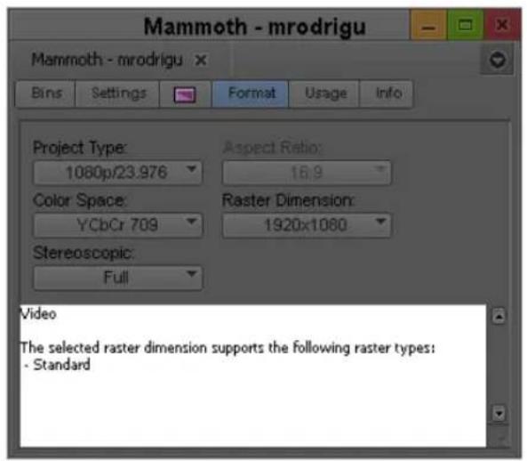
For some project formats, the Project Type list lets you change the format of the project to another format that shares the same frame rate. For example, if you are working in a 1080i/59.94 HD project, you can change the project format to 30i NTSC.

If you switch from one project type, aspect ratio, color space, or raster dimension to another during the course of your workflow, you might create precomputed clips that have not rendered with the quality that you need for your final output. You might need to manually purge the precomputed clips and re-render effects. For more information, see “Ensuring the Quality Level of Precomputed Clips” in the Help.

For 24p PAL projects, the Format tab shows the audio transfer rate you selected when you created the project. The actual audio transfer rate might be different from the display if you used the Film and 24P Settings dialog box to change the audio transfer rate.
To open the Format tab:
▶Click the Format tab.
Using the Usage Tab
The Statistics feature gathers and reports information on system usage. You can use this information to support business functions such as resource management.
All statistics are gathered and reported by project. The file that contains this information is formatted so you can use it as input to software programs such as analysis applications, spreadsheets, or report generators.

Do not rely on the Statistics feature for billing or other financial purposes.
To view and update statistics for an open project:
▶Click the Usage tab in the Project window.
To print the Statistics file:
▶Select File > Print Usage.
Statistics File Structure and Layout
A new Statistics file is created each time you open the project. The files are stored in a Statistics folder inside each project folder.
The file name has the following format:
Statistics.yymmdd.HHMMSS
where:
Variable Description
yy Indicates the last two digits of the year
mm Indicates the month
dd Indicates the day
HH Indicates the hour
MM Indicates the minutes
SS Indicates the seconds
The statistics file is formatted as comma-separated ASCII text, so it can be accepted by a variety of software programs. Each line in the file is tagged with indicators for identifying content and data type to assist in programming custom applications. The following illustration shows a sample Statistics file.

The values in the first column indicate the content of the line:
01 title1
02 title2
03 Title Only
100 project info
101 Time Project open
102 Capture tool open
104 Capture tool active
105 Captured Media bytes used
106 Rendered Effects bytes used
110 Effects rendering time
111 Title tool open
113 Title tool active
114 Title tool rendering
115 Capture tool capturing
116 Capture tool logging
117 user comments
The values in the second column indicate the type of data in the line:
01 project info
02 time used
03 bytes used
04 text string
Importing the Statistics File into a Spreadsheet
You can import the Statistics file into a spreadsheet or other program as an ASCII file and use your Avid editing application to set up the proper format.
To import a Statistics file into Microsoft Excel:
- Start Microsoft Excel.
- Select File > Open, and navigate to the Statistics file you want to import.
(Windows only) Make sure All Files (*.*) is selected in the Files of Type list. - Click Open.
The Text Import wizard starts.
- Select Delimited for the Original Data Type, and click Next.
- Select Comma for Delimiters, and click Next.
- Select General for Column Data Format.
- Click Finish.
The statistics file appears in spreadsheet format.
The following illustration is the sample file from the previous section as it appears when you import it into a spreadsheet.
| Statistics.980824.111304 | |||||||||
| A | B | C | D | E | F | G | H | I | |
| 1 | 1 | 1 | Project Name: Flower Show | Statistics as of: Mon Aug 24 11:38:58 2002 | |||||
| 2 | 2 | 1 | Project created: Tue Aug 18 13:50:00 2002 | Last Session Started: Mon Aug 24 11:13:04 2002 | |||||
| 3 | 117 | 4 | |||||||
| 4 | 3 | 4 | |||||||
| 5 | 3 | 4 | Elapsed Time: | --- | Total | --- | --- | Last Session | --- |
| 6 | 3 | 4 | Hours | Minutes | Seconds | Hours | Minutes | Seconds | |
| 7 | 101 | 2 | Time Project Open | 124 | 10 | 42 | 0 | 25 | 54 |
| 8 | 3 | 4 | |||||||
| 9 | 102 | 2 | Capture Tool open | 0 | 0 | 0 | 0 | 0 | 0 |
| 10 | 104 | 2 | Capture Tool active | 0 | 0 | 0 | 0 | 0 | 0 |
| 11 | 116 | 2 | Capture Tool logging | 2 | 43 | 18 | 0 | 21 | 47 |
| 12 | 115 | 2 | Capture Tool capturing | 0 | 2 | 42 | 0 | 1 | 11 |
| 13 | 3 | 4 | |||||||
| 14 | 111 | 2 | Title Tool open | 2 | 39 | 30 | 0 | 3 | 41 |
| 15 | 113 | 2 | Title Tool active | 2 | 54 | 18 | 0 | 5 | 47 |
| 16 | 114 | 2 | Title Tool rendering | 0 | 0 | 0 | 0 | 0 | 0 |
| 17 | 3 | 4 | |||||||
| 18 | 110 | 2 | Effects rendering | 0 | 22 | 8 | 0 | 3 | 16 |
| 19 | 3 | 4 | |||||||
| 20 | 3 | 4 Disk Space Used: #Files m Bytes Used | |||||||
| 21 | 105 3 Captured Media 0 0 | ||||||||
| 22 106 3 Rendered Effects 0 0 | |||||||||
| 23 3 4 | |||||||||
| 24 3 4 | |||||||||
| 25 3 4 * Items marked by asterisk may show less than actual usage | |||||||||
Displaying Disk Space Statistics
You must use a Console command to calculate and display statistics for disk space in the Usage window.
To display disk space statistics in the Usage window:
- Select Tools > Console.
- In the command entry text box, type:
toggleStatSpace
- Press Enter (Windows) or Return (Macintosh).
- Select File > Load Media Database.
After the media database is loaded, the Usage window displays the number of files and disk space used for captured media and rendered effects.
To update the display:
▶Click the Usage tab in the Project window.
To prevent recalculation:
▶Reenter the toggleStatSpace command.
Using the Info Tab
The Info display in the Project window lets you view system memory information and access the Hardware tool. The items listed in this display are for information only and cannot be changed. The Hardware tool gives a visual representation of usage for each drive and provides operating system information.
To open the Info display:
▶In the Project window, click the Info tab.
To display system memory information:
In the Project window, click the Info tab, and then click the Memory button. The Memory window opens with the following information:
Item Description
Objects The total number of memory handles currently used by your Avid
editing application. Objects include memory requirements of your Avid editing application, such as windows, clips, sequences, and other items associated with a project.

You can improve the performance of large projects when you reduce the number of objects. To do this, close unused bins, unmount unused media drives, consolidate finished elements, eliminate old material from the project, or divide the project into separate projects. Then quit and restart your Avid editing application. If performance is still slow, restart your system.
Total physical memory (Windows) or The total number of bytes of RAM (random-access memory). Total Mem (Macintosh)
Available physical memory (Windows) The amount of RAM available for allocation by the Windows or Free Mem (Macintosh) Macintosh system.
Item Description
Total page file The total number of bytes stored in the paging file. The paging file is used as virtual memory by the Windows system.
Available page file The total number of bytes available in the paging files.
Working set (minimum and maximum) The set of memory pages currently available to your Avid editing application in RAM.
To open the Hardware tool, do one of the following:
In the Project window, click the Info tab, and then click the Hardware button.
▶Select Tools > Hardware.
The Hardware tool opens.

For more information about the Hardware tool, see “Using the Hardware Tool” on page 116.
Managing Bins and Memory
System memory usage increases depending on how many bins you have open, the number of sequences in a bin, the number of tools that are open, and the size of a sequence. Using more memory can slow system performance.
In the Bin tab of the Project window, a memory usage indicator increases and updates as you open and close bins. Avid recommends that you keep memory usage below 80-85%. If you exceed the recommended usage, a dialog box opens informing you that your memory usage is high and recommends that you close some bins and save your project.
If your system is running low on memory and you need to free up memory, you can either close your bins or use the Clear Memory button. If you close your bins, some of your memory remains unavailable until you exit your Avid editing application because the online master clips remain in memory. The Clear Memory button, however, closes and saves all of your open bins and clears out any cached data of the online master clips.
Bins containing sequences use more memory than bins containing master clips. For bins that contain a large number of sequences, you can free up memory and still keep your old sequences. Create an archive bin and move older sequences that you do not use anymore to the archive bin. Keep the archive bin closed.
To free up memory:
- Click the Info tab of the Project window.
- Click the Clear Memory button.
A dialog box opens asking if you want to close and save all opened bins.
3. Click OK.
This operation deletes cached data for the online master clips only. Memory might also be used by other parts of your Avid editing application and will not be reduced by using the Clear Memory button.
Understanding User Profiles
User profiles let you switch between settings without having to log out of your system and log back in under a different user name.
User profiles let you establish separate settings for different editing functions. User “Jane,” for example, can have separate profiles for “Audio editor,” “Film editor,” or for “Assistant 1,” “Assistant 2,” and so on.
User profile folders are kept in the following folder:
Windows XP drive:\Documents and Settings\All Users\Shared Documents\Avid editing application\Avid Users\UserName
Windows Vista and drive:\Users\Public\Public Documents\Avid editing application\Avid Windows 7 Users\UserName
Macintosh /Users/Shared/Avid editing application/Avid Users/UserName
You can do the following with user profiles:
- Create new user profiles
- Switch between user profiles
- Return to the original user profile
- Import settings from another user or user profile
- Create a user profile on one system, export it to a server, and then import the same user profile from another system to the new system.
When you export a user profile, you can select either a Personal or Group profile.
- When you select Personal, the user profile performs an auto-load and an auto-save every time you open a project. Every time the user profile is updated, it saves the new profile information. For example, you can create the user profile Jennie on one system, export it
to another location (a server), and then import it to a different system. Any time you change the Jennie user profile, it updates to the server and when you open the Jennie user profile on either system, it uses the most updated Jennie user profile.
- When you select Group, the user profile auto-loads but it does not auto-save. Changes made to the user profile only affect the system where you made the change. The changes do not update to the server.

When you export User Profiles in an Avid shared storage environment, make sure the workspace containing the user profile has the same drive letter on all systems.

You can not share user profiles across platforms (Macintosh to Windows or Windows to Macintosh).
- Update a user profile to add user settings to an existing Settings list.
For example, if you upgrade to a version of your Avid editing application that contains the Send To option from a version that did not have that option, you can choose the Update User Profile option to make sure the Send To settings templates appear in your Settings list.
For step-by-step procedures, see "Managing User Profiles" on page 88.
Managing User Profiles
To create a user profile:
- Click the Settings tab in the Project window.
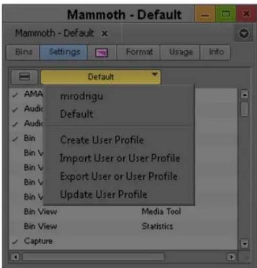
The User Profile Selection menu in the Settings tab of the Project window
- Click the User Profile Selection menu, and select Create User Profile.
The Create User Profile dialog box opens.
- Type a name in the Profile Name text box, and then click OK.
The new user profile appears selected in the menu, and the user profile name appears in the Project window title bar.
To import user settings from another user or user profile:
- Click the Settings tab.
- Click the User Profile Selection menu, and select another user profile.
- The new user profile name appears in the Project window title bar.
To return to the original user profile:
- Click the Settings tab.
- Click the User Profile Selection menu, and select the default user profile.

If you use a user profile other than the default and you change to another project, the default user settings load, even though the Project window displays your non-default user profile name. You must reselect the user profile.
To import user settings from another user or user profile:
- Click the Settings tab.
- Click the User Profile Selection menu, and select Import User or User Profile.
- Navigate to the user or user profile you want to import.
To export user settings to another user or user profile:
- Click the Settings tab.
- Click the User Profile Selection menu, and select Export User or User Profile.
- Select Personal or Group.
- Navigate to the location where you want to place the user or user profile.
- Click OK.
To update user profiles:
- Click the Settings tab.
- Click the User Profile Selection menu, and select Update User Profiles.
Any new settings added to the upgraded version of your Avid editing application appear in the Settings list.
To delete a user profile from your desktop:
- Navigate to the Avid Users folder, and then select the user folder you want to delete. For information about the location of the Avid folders, see “Avid Projects and Avid Users Folders” on page 46.
- Do one of the following:
▶ (Windows) Press the Delete key, then click OK in the dialog box.
▶(Macintosh) Drag the folder to the Trash.
- Empty the Recycle Bin (Windows) or the Trash (Macintosh) to remove the files from the system.
- Close the windows, and restart your Avid editing application.
The deleted user no longer appears in the Select Project dialog box.
Customizing the Avid User Interface
The Interface Settings dialog box provides you with controls for customizing the brightness and the colors of the Avid user interface. For complete reference information on the Interface Settings dialog box, see “Interface Settings” on page 1420.
The Interface Settings dialog box allows you to set the highlight color for buttons. You can also control the brightness of the user interface, which includes the following components:
- Application, tool, toolbar, and dialog box backgrounds
- Buttons and button contents
- Project background
The Avid editing application lets you modify the colors of some interface components using controls not included in the Interface Settings dialog box:
- Bin media object color — see “Assigning Colors to Objects in a Bin” on page 341.
• Timeline clip color — see “Displaying Clip Colors in the Timeline” on page 672.
• Timeline track colors — see “Changing the Track Color” on page 676. - Bin background color — see “Changing the Bin Background Color” on page 340.
Changing Interface Component Colors
You can use a brightness selection slider and selection buttons to change the appearance of some interface components.

When you use the selection slider to modify interface settings, it overwrites any previous user settings. Avid recommends you save a copy of your user settings before you use the selection slider.
To set the brightness and color of interface components:
- In the Project window, click the Settings tab, and then double-click Interface. The Interface dialog box opens.
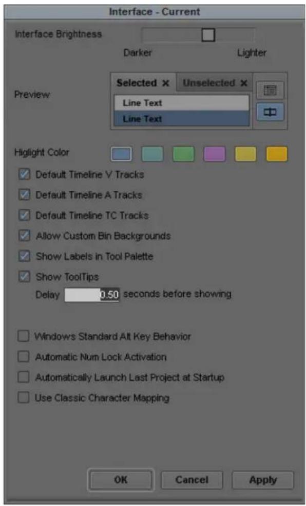
- Click a highlight color to change button highlight colors.
- Click the Interface Brightness slider to adjust the brightness of the user interface. The Avid editing application provides several presets on the slider.
-
(Option) If you want to set the color of the video, audio, or timecode tracks to the default, select the appropriate option.
-
(Option) If you want to be able to set custom background colors for bins, select Allow Custom Bin Backgrounds.
For more information, see “Changing the Bin Background Color” on page 340.
- Do one of the following:
▶Click Apply to apply the changes you selected.
If you click Cancel after you click Apply, interface components retain the colors you applied.
▶ Click OK to close the dialog box and put the new setting into effect.
▶Click Cancel to close the dialog box.
The changes you select do not take effect.
Changing Font and Point Size
You can change the default font and point sizes of the Project, Bin, Composer monitor, Script, and Timeline windows. You can vary the fonts and point sizes across these windows. For example, you can set the Project window to Helvetica, 13 pt.; set one Bin window to Times Roman, 11 pt.; and set another Bin window to Arial, 12 pt.
The table describes the windows you can change, and where these changes are saved.
Window Location of Changes
| Project Changes the font and point size of the text in the Project window; saves as a Project setting. | |
| Bin Changes the font and point size of the text in the Bin window; saves as a Bin setting (not a Bin View setting). | |
| Composer monitor | Changes the font and point size of the sequence or source clip name text; saves as a Composer setting. |
| Script Changes the font and point size of the text in the Script window; saves as a Script setting. | |
| Timeline Changes the font and point size of clip text; saves as a Timeline View setting. | |
To change the font in the Project, Bin, Composer monitor, Script, or Timeline window:
- Click the Project, Bin, Composer monitor, Script, or Timeline window to make it active.
- Select Edit > Set Font.
The Set Font dialog box opens.
- Click the Font menu, and select a font.

Any font installed on the Avid system appears in the list. For information on adding fonts to your system, see the documentation for your operating system.
- Type another point size for the font in the Size text box.
- Click OK.
The new font and point size appear in the active window.
When you close the window, the last font and point size applied are saved with the window.
Using Workspaces
Your Avid editing application provides default layouts of windows and tools designed to utilize the application interface efficiently. These layouts are organized as workspaces, and the default workspaces include the following:
- Audio Editing
- Color Correction
- Source/Record Editing
- Effects Editing
• C a p t u r e
If you are accustomed to working with a particular group of windows arranged and sized in a particular setup, you can assign them to a workspace setting that you can then recall with a workspace button.
For example, during capture you might want to display the Capture tool and Video Input tool in specific locations. During effects editing, you might want to display the Effect Palette and Effect Editor in particular locations and sizes.
While in a workspace, you can move tool windows or open and close tool windows. The next time you select that workspace, the tool windows appear with the arrangement you set for the workspace.
You can assign up to 12 buttons that let you switch between workspaces. Workspace settings are user settings, so different users can have separate workspace arrangements. This is useful if there is more than one user accessing the same Avid system. Each user can assign up to 12 workspaces. You can also link the mode buttons in the Timeline palette to specific workspaces. And you can map the Workspace buttons in the Command palette to toolbars in the Timeline; in the Tool palette, or to a keyboard setting.

You cannot assign certain tool windows to a workspace, such as the Hardware tool, the Communication (Serial) Ports tool, and the Media tool.
To select a workspace, do the following:
▶ Select Windows > Workspaces > workspacename.
To customize the workspace:
- For the workspace you want to customize, select Windows > Workspaces > workspacename.
- Open other tools with which you want to work, and position them where you want them.
- Select Windows > Workspaces > New Workspace.
- Type a name for the new workspace in the Workspace Name text box.
- (Option) Select Based on Workspace, and then select a different workspace from the active one.
- Click OK.
The new workspace appears in the Workspaces menu.
To remove your customizations:
-
Select Windows > Workspaces > Restore Current to Default. A message box warns you that the action deletes your custom workspace settings.
-
Click OK.
The workspace settings revert to the default settings on which you based the customizations.
To link a mode button in the Timeline palette to a workspace:
-
In the Settings list of the Project window, double-click Workspace Linking. The Workspace Linking Settings dialog box opens.
-
Click one of the following, and then select a workspace to which you want to link a mode button:
▶Source/Record mode
▶Effects mode
▶Color Correction mode
The mode button is linked to the workspace.
- Click OK.
When you click the mode button in the Timeline palette, the assigned workspace opens.
To delete a custom workspace:
- Select Windows > Workspaces > Delete Workspace.
The Delete Workspace dialog box opens. - Click OK.
The active workspace is deleted.
Linking User Settings and Workspaces
You can link User settings to a workspace. You can create a customized workspace, set up specific options in any Settings dialog box, and link them together by name.
For example, you can create an Audio workspace that opens the Audio Mixer tool and Audio tool. This workspace can also open a customized Timeline (with enlarged audio tracks and rubberbanding displays).
To link a workspace to another setting:
- Select Windows > Workspaces > workspacename for the workspace you want to link.
- In the Settings list of the Project window, create a new setting for any setting you want to link to your workspace. For information on creating custom settings, see “Duplicating Settings” on page 1342.
- Double-click a setting that you want to link to your workspace, and change the settings you want to customize — for example, click Timeline and then select the Timeline settings you want.
- Name this setting with the same name of your workspace. For more information, see "Naming Settings" on page 1343.
- Double-click another setting. Select the options you want, close the dialog box.
- Name this setting with the same name of your workspace.

Examples of linked settings (top and center) and a linked workspace view (bottom)
- In the Settings list of the Project window, double-click the workspace you want to link. The Workspace View Setting dialog box opens.
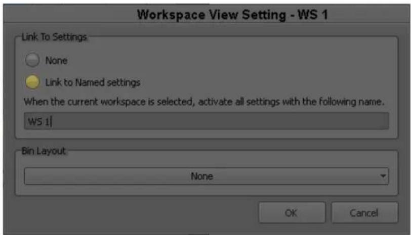
- Select Link to Named settings.
- Type the name of the custom settings to which you want to link the workspace.
For more information about creating and naming custom settings, see “Working with Settings” on page 1339.

You can link workspaces only to User settings.
-
(Option) Click the Bin Layout menu and select a layout you want to link to the workspace. For more information, see "Using Bin Layouts" on page 98.
-
Click OK.
The workspace is linked to the custom setting you specified.
To link a workspace to an unnamed setting:
- Do one of the following:
For the workspace you want to link, select Windows > Workspaces > workspace.
In the Settings list of the Project window, double-click the workspace you want to link.
The Workspace View Setting dialog box opens.
- Select Link to Named settings and make sure there is nothing entered in the text box below it.
- Click OK.
The workspace is linked to all the unnamed settings in the Settings list.
Assigning a Workspace or Bin Layout Button
When you assign a workspace or bin layout to a button, the button displays the first two characters of the workspace or layout name. If the assigned workspace or layout is not available — for example, if you deleted the workspace or the bin layout — the button remains visible but the label displays italicized characters.
To assign a workspace button:
- Select Tools > Command Palette.

Workspace buttons in the Workspaces tab of the Command Palette
-
Click the Workspaces tab.
-
Select Button to Button Reassignment.
- Click a workspace button and drag the button to a location on another palette (for example, the Tool palette) or the Keyboard setting.
The workspace button appears in the new location.
To assign a bin layout button:
- Select Tools > Command Palette.
- Click the Workspaces tab.
- Click the workspace menu next to the button you want to assign.
Bin layouts appear in the menu below the divider line.
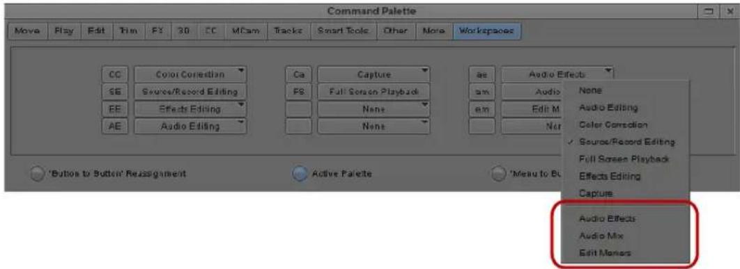
Bin Layout menu in the Workspaces tab of the Command Palette
- Select Button to Button Reassignment.
- Click a bin layout button and drag the button to a location on another palette (for example, the Tool palette) or the Keyboard setting.
The bin layout button appears in the new location.
Using Bin Layouts
You can arrange and save bin window configurations independently of workspaces, including the contents of bin windows containing tabbed bins. You can also link a specific bin layout to a workspace. This allows you to open bin layouts at any time to customize the interface of your Avid editing application.
When you open a bin layout, the Avid editing application opens all bins saved in the bin layout and places them in the position configured in the layout. If you close the application, the position of bins in your current configuration is saved but not the bin layout setting. To save a custom bin layout, you must use the Bin Layout menu.
Keyboard settings and toolbar button mappings for workspaces are user settings. Bin layouts are project settings. When you link bin layouts to workspaces, to keyboard settings, or to toolbar buttons, you can access these layout assignments only when you work in a project containing a bin layout with the same name as when you created the link. For this reason, you should be careful to maintain a consistent bin layout naming convention for your projects.
If you delete a bin layout, the layout is deleted from your project. If you have an identical bin layout in another project, the layout is deleted only from the open project.

If you assign a bin layout button to a toolbar or a keyboard setting, deleting the bin layout does not remove the bin layout button. To remove the bin layout button, you must either assign a different button or a blank button to the toolbar or keyboard setting.
To open a bin layout, do the following:
▶ Select Windows > Bin Layout > bin layout.
To save a custom bin layout:
- Select Windows > Bin Layout > New Bin Layout.
The New Bin Layout dialog box opens.
- Type a name for the bin layout, and then click OK.
The application saves the bin layout, and the layout appears in the Bin Layout menu and in the Settings tab of the Project window.
To link a bin layout to a workspace view:
- Do one of the following:
▶Select Windows > Workspaces > Properties.
In the Settings tab of the Project window, double-click the Workspace View you want to link.
The Workspace View Setting dialog box opens.
-
Click the Bin Layout menu and select a bin.
-
Click OK.
To modify a bin layout:
-
Arrange and size your bins.
-
Select Windows > Bin Layout > Save Current.
To delete a bin layout:
- Select Windows > Bin Layout > Delete Bin Layout.
The Delete Bin Layout dialog box opens.
2. Click OK.
Working with Bins and Projects in an Avid Shared Storage Environment
Avid ISIS let you share bins and projects across the network. When you place your bins and projects on Avid Workspaces (drive volumes), several users can work on the same project at the same time.
For example, an editor creates sequences in one bin while an assistant recaptures media in another bin. At the same time, other users add audio effects or titles to other bins in the project.
Each user performs tasks from their own computer. Your Avid editing application provides a locking mechanism to help you keep track of who is currently working in a bin. The method allows one user to write to a bin; multiple users can read the files in that bin.

The lock does not prevent you from deleting the media in a locked bin if you have write access to the workspace. It ensures only that you do not overwrite changes to the bin.
In an Avid shared storage environment, your Avid editing application creates and stores projects and bins on the client's internal drive. If you move or save these projects and bins to the workspace, only one client can work on the project at a time. If two or more users work simultaneously on the same project, only one user can update the files. Other users can open and play sequences but cannot make any changes to them.
For information on managing workspaces, see the clients' Quick Start cards.

You can also use an asset manager such as Avid Interplay to collaborate on projects. For more details, refer to “Working with Avid Interplay from an Avid Editing System” on page 1134.
Sharing Bins and Projects in Avid Shared Storage
Sharing Only Bins
If you share only bins, you store the project on your local system and store bins and media files on the shared workspace. This method allows users in a shared environment to share only selected bins with other users. The system identifies the shared bins as follows:
- Stores the bin in a Unity Bins folder in the Project window. This folder is similar to the Other Bins folder.
- Displays a second column of information for the bin that identifies the computer that currently has the bin locked.
- Uses bold text to identify bins that are locked by another user.
Sharing Both Bins and Projects
If you share bins and projects, you create and store the project folder and bins on the shared workspace (or copy an existing project, bins, and the related media files). Your Avid editing application identifies information from each computer using the shared workspace as follows:
- Creates a project folder for each computer that accesses the project. Your Avid editing application adds the computer's name to the folder name to create a unique name and stores any project-specific information in the folder. This prevents users from overwriting the project-specific data for other users.
- Displays an extra column in the Project window that identifies the computer that has the bin locked.
- Uses bold text to identify bins that are locked by other users.
- Creates a folder at the top level of the shared workspace called Unity Attic. This folder contains backup files for each project on the shared volume.

Depending on the number of users sharing a workspace, you might want to increase the number of files that your Avid editing application stores in the Unity Attic folder.
The following illustration shows the Project window for a shared project.
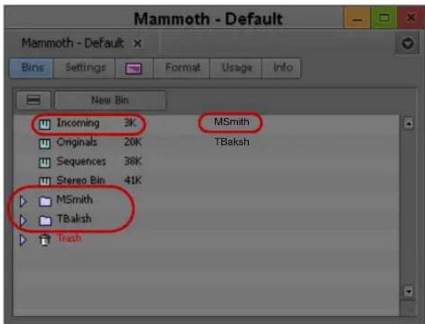
Bins tab in the Project window, showing a bin that is locked for editing (bold text, top left), the name of the computer that currently has the bin locked (top right), and folders for each computer that accesses the project (bottom)
Opening a Shared Project
To open an existing project on the shared volume:
- Start your Avid editing application.
- In the Select Project dialog box, navigate to the project on Avid shared storage.
The Project window opens. For a description of the elements specific to Avid shared storage in the Project window, see “Sharing Bins and Projects in Avid Shared Storage” on page 100.
- Double-click a Bin icon to open one of the bins.
The bin appears with a Bin Lock Status button. You can click the red (locked) or green (unlocked) Bin Lock Status button to view a history file that shows which computers and users have modified the bin and the date and time of the modifications.

The Bin Lock Status button. When the button is green (top), the bin is unlocked. When the button is red (bottom) the bin is locked.
When a bin is unlocked, you have permission to make changes. You should not make changes to a locked bin. See “Considerations for Working with Shared Bins and Projects” on page 103.

The Bin Lock Status button does not appear if the bin is not on Avid shared storage.
Working with Locks and Shared Bins
Your Avid editing application uses a locking mechanism to help you keep track of who is currently working in a shared bin. Only one user can write to the bin, but multiple users can read the files in the bin.
The user who opens the bin first controls the lock and obtains write access to the bin. Bold text in the Project window also identifies bins that are locked by another user. When the person who controls the lock closes the bin, it becomes available for another user to open and control the lock.
If one user has the lock and another user has the same bin open, when the first user closes the bin, the second user must close and reopen the bin to control the lock.
You can instruct your Avid editing application to keep a bin locked even after you close it.
You can click the red or green Bin Lock Status button in the bin to view a history file that shows which computers and users have modified the bin.
To open a bin without controlling the lock:
Alt+double-click (Windows) or Option+double-click (Macintosh) the bin in the Project window.
To permanently lock a bin:
- Select one or more bins in the Project window.
- Right-click the Bin icon, and select Lock Project Bin.
An asterisk appears next to the user name in the Project window. In this case, the bin remains locked even after you close it.
To unlock the bin:
▶Right-click the bin in the Project window, and select Unlock Project Bin.

The Lock Project Bin and Unlock Project Bin commands are also available from the Clip menu.
Considerations for Working with Shared Bins and Projects
Suggestions for Improving Performance When Working with Shared Bins
The following information is provided to improve performance when working with shared bins in an Avid shared storage environment.
- Do not use the same name for your editing system machine name and your user name. Do not use the same name for security objects such as machine names, user names, group names, and domain names. If any two security objects have the same name, Windows might become confused and sharing might not work properly. - Do not use the same prefix for machine names in a shared environment. No full name can be a prefix of another name. If one of the systems has a machine name that is the full name, and others in the environment have the prefix as part of their machine name, problems can occur. For example, if an editing system has a machine name ABC and additional editing systems in the shared environment have machine names ABCnn, ABCxx, the following problems could occur:
- When the system with the machine name ABC is writing to a directory, the systems whose machine names have the same prefix (ABCnn and ABCxx) might not be able to access the directory.
- When the system with the machine name ABC is rendering, systems whose machine names have the same prefix (ABCnn and ABCxx) might be unable to launch.
Avid recommends that you do not use a common prefix for machine names. If you must use a common prefix, make sure all the names are the same length (ABC01, ABC02, ABC03, etc.).
- Do not use Windows Explorer to examine, copy, or manipulate shared bin files or shared project folders or their contents when you use those files or folders. If you do, when you attempt to access those shared bins or projects you might experience delays accompanied by a progress dialog that says, “Filesystem busy, retrying (MESSAGE).”
If the busy condition persists, a failure message appears. Make sure that you are not using Windows Explorer for the shared bins you are trying to access, and then try the operation again.
- When you have an environment where more than five users are sharing bins on Avid shared storage, Avid recommends using an Avid Interplay server in the workgroup environment.
- When an Avid Interplay server is available in an Avid workgroup environment, Avid does not recommend sharing bins or projects. Use the Avid Interplay server and the Interplay Window to share media. All editing systems in a workgroup environment that includes an Avid Interplay server must have the Avid shared storage client software installed. The Media Tool might become unreliable if an editor in the Avid shared storage workgroup environment does not have the Avid shared storage client software installed.
Limitations When Working with Shared Bins and Projects
If an editor other than the creator deletes a media file, other editors cannot see that media file go offline immediately. If an editor tries to play that file, a “media file not found” message might appear in a monitor window, and an access violation error might occur.
Each editing application maintains a PMR file in its machine name folder inside the OMFI MediaFiles folder or the Avid MediaFiles folder. The PMR file lists all the online media files. Every editing application consults all the PMR files in all the machine name folders to find out which media files are online. Whenever a media file is created, its name is immediately added to the creating editor application's PMR file, and whenever a media file is deleted by its creator, its name is immediately removed from the PMR file.
However, if an editing application other than the creator deletes a media file, the PMR file that contains the deleted file is NOT updated immediately. Once the creating editor encounters an event that causes its PMR to be updated, then all editing systems know that the deleted media file has gone offline.
There are several ways to force an editing application to update its PMR. The simplest is to switch to the desktop and back.
Avid recommends that you institute policies where media files are deleted by the editor who created them, or if necessary, the deleting editors notify the editor who created the media files that a deletion has occurred. This editor can then switch to the desktop and back, and all other editors can see the deleted file go offline.
Restrictions and Limitations for Locked Bins
The following restrictions apply to bins that are locked by another user:
- You cannot select a locked bin for operations such as capture, title creation, and import. This helps to minimize the problems of modifying a locked bin.
- You cannot drag an item to a locked bin.
- If you drag an item from a locked bin to a writable bin, the Avid system creates a duplicate (not a copy) of the selection in the writable bin. The original item is not removed from the locked bin. This operation is the equivalent of duplicating a selection and then drag the duplicate to another bin.
- You cannot move a bin that is locked by another user.
- If you modify a locked bin, your Avid editing application does not let you save the bin to the same name, but it lets you save the bin to another name. However, this causes duplicate bin IDs and might cause system-level conflicts with the contents of the two bins. Your Avid editing application sees the duplicate contents of these bins and resolves the conflicts by newest modifications.
Avoid creating duplicate bins when you modify a locked bin. If you do create a duplicate bin, you should manually merge the changes into the original bin and delete the duplicate bin.

The lock does not prevent you from deleting the media in a locked bin if you have write access to the workspace. It ensures only that you don't overwrite changes to the bin.
Limitation When Using the Shared Bin Lock Icon
Occasionally, when two editors attempt to open a shared bin at the same time, both editors get the green lock icon. However, only one editor really has the lock, and that editor's machine name appears beside the bin name in both Project windows.
Both editors can modify their copies of the bin, but only the editor that controls the lock, as indicated in the Project window, can save that bin. The other editor is warned that the bin is locked but is allowed to save a copy of the changed bin.
Avid recommends that you use the “Save Bin Copy As...” button and continue working.
Drive Filtering in Networked Workflows
The Drive Filtering and Indexing tab of the Media Creation Settings dialog box includes three options:
- Filter by Resolution
- Filter by System Drive
- Filter by Launch Drive
Depending on the version of your Avid editing system, the drive filtering options could be on or off by default. Avid recommends that all drive filtering options should be on by default.

Any project brought into a networked workflow that was created with any of the filtering selections off might have problems with networked media creation, such as “Audio and/or Video Mixdown” and “Send To Playback,” because their Media Creation Settings are still configured for standalone usage.
There are several ways to work around this issue. First, adjust the drive filtering settings when you switch environments. You can open the Media Creation Setting and switch the drive filtering settings or create multiple Media Creation Settings and switch the active setting whenever you shift environments. If you always work in an environment that differs from the defaults, you can create a Media Creation setting that fits your workflow and add it to your Site Settings so you create new projects with the desired defaults. For more information, see “Using Site Settings” on page 1347.
4 Using Tools
The Tools menu provides quick access to essential tools that you can use in your projects. In addition to the tools available from the Tools menu, you can also add a controller to your system that you can use as an alternative to your keyboard and mouse for editing footage. These tools are described in the following sections:
• Using the Tools Menu
• Using a Deck Controller
- Deck Controller Window Reference
• The Command Palette
• Using the Avid Calculator
• Using The Console Window
• Using the Hardware Tool
• External Controllers as Editing Control Surfaces
Using the Tools Menu
To open a tool:
▶ Select Tools > tool name.
Using Tabs
When you open a tool, it opens in a separate window by default. however, you can drag tools to a single tab window to conserve space within your Avid editing application, and you can move tools between tab windows.

You can move tools into tab windows that contain other tools. You cannot move tools into tab windows used for bins. For more information on using bin tabs, see “Using Bin Tabs” on page 334.
To move a tool into a window:
▶Click the tab in the tool you want to move, and drag it to the target window.
The tab bar in the target tab window displays all tool tabs.
To move a tool into separate window:
▶ Click the tab for the tool you want to move, and drag it to a clear region of the application interface.
The tool displays in a separate window.
To view tool tabs that do not display in the tab bar, do one of the following:
▶ Click the Previous Tab button or the Next Tab button to shift the tab view to the left or the right.
The tab display adjusts to display the next tool either on the left or the right.
▶Click the Tab menu, and then select the name of the tool you want to view.
The selected tool displays in the tab window.
To organize tools by changing the order of tabs:
Click the tab of a tool you want to move, and drag it to a new position in the tab row.
To close a tool tab:
▶Click the Close button in the tab.
Using a Deck Controller
A deck controller provides direct serial or VLXi ^® V-LAN ^® control of an Avid-compatible tape deck at any time while you edit. You can cue and screen footage from source tapes in various edit modes, or when you record a digital cut, without opening the Capture tool.
To open a deck controller:
▶Select Tools > New Deck Controller.
A new Deck Controller window opens.
Deck Controller Window Reference

Element Description
1 Timecode display Provides information about the control status of the tape deck:
- If the deck is properly connected and power is on, the deck controller displays timecode when you mount a tape.
- If a deck is not properly connected to the system or power is off when you open the controller, the indicator displays the message "NO DECK."
- If you turn the deck power off with the deck controller open, the indicator displays the message "Power Off."
- If you switch the deck control to Local on the VTR, the indicator displays the message "Local."

Information on connecting decks and cabling varies depending on the Avid input/output hardware device you use. For more information, see "Connecting Cameras, Decks, and Monitors" in the Help.
2 Timecode indicator Flashes green during playback or capture to indicate that the system is receiving valid timecode from the source tape. If the indicator remains unlit, the system is not receiving timecode.
3 Deck controls Provide a standard range of playback capabilities, including fast forward and rewind, stop and play, step backward and step forward, pause, and eject.
4 Deck Selection menu Lets you specify a deck with deck control parameters that you can customize. For more information, see "Deck Configuration Settings" on page 1372.
5 Tape Name button Lets you associate a tape name with the controller and select a tape. For more information, see "Selecting a Source Tape" on page 188.
Element Description
6 Logging controls Let you log IN and OUT marks while you cue your tape. For more information on logging, see "Logging Directly into a Bin" on page 138.
The Command Palette
The Command palette provides a central location for all user-selectable buttons that you can map to various locations for ease of use. User-selectable buttons let you perform a wide range of commands with a single click of the mouse.
The Command palette organizes buttons by editing function. Tabs display each editing function and the buttons that perform those functions display in each tab. The functions include: Move, Play, Edit, Trim, FX (Effects), 3D, CC (Color Correction), MCam (MultiCamera), Other, More, and Smart Tool.
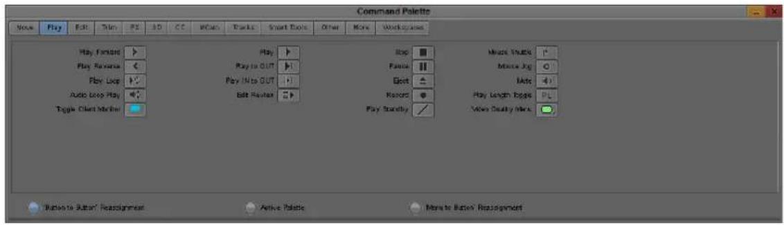
You can use the Command palette to:
- Map buttons to any Tool palette or the keyboard. See “Mapping User-Selectable Buttons” on page 112.
- Map menu commands to various buttons and keys. See “Mapping Menu Commands” on page 113.
- Directly activate a command. See “Activating Commands from the Command Palette” on page 114.

For information about each button in the Command palette, right-click a button and select What's This? from the menu.
Understanding Button Mapping
Mapping user-selectable buttons lets you reconfigure Tool palettes, toolbars, or the keyboard in various combinations to suit different editing needs.

When you map buttons to the keyboard, the mapping might be specific to the current editing mode. For example, buttons mapped to the Page Up key or the Page Down key revert to the default key functions when you enter Effect mode. After you exit Effect mode, the keys return to the mapped function.
The following are examples of buttons you might want to map:
Buttons you use to subcatalog clips. Left to right: Make Subclip, Find Bin, and Add Marker.

Buttons you use for complex layering and effects. Top, left to right: Motion Effect, Remove Effect, Transition Corner Display, and Fade Effect. Bottom, left to right: Render Effect, Cycle Picture/Sound, Quick Transition, Grid (available on some Avid editing applications).
Buttons you use for MultiCamera editing. Left to right: Quad Split, Swap Cam Bank, and Group.
When you remap buttons or commands, the system immediately saves your new configuration in one of the default settings that you open from the Project window. You can also save, rename, and recall multiple versions of any of these settings to serve various purposes.
For more information on multiple settings, see “Selecting Among Multiple Settings” on page 1344.
Your Avid editing application saves button configurations as follows:
- Changes to the Keyboard palette are saved in the Keyboard settings.
- Changes to Tool palette in the Composer window are saved with the Composer settings.
- Changes to Command palettes while trimming are saved with Trim settings.
- Changes to the Tool palette are saved in the Interface settings.
To change the appearance of the buttons in the Tool palette in the Interface settings, see “Customizing the Avid User Interface” on page 90. To identify a button’s function with only an icon or with an icon and letters, see “Interface Settings” on page 1420.
The Blank Button

The Blank button in the Other tab of the Command palette lets you replace a defined button with an undefined button. If you do not need a specific button on the Tool palette, you can replace this button with a Blank button.
For more information on mapping the Blank button to a new location, see “Mapping User-Selectable Buttons” on page 112.
Modifier Keys
You can add modifier keys to functions already associated with keys and buttons. The Other tab in the Command palette contains the following modifier key buttons:
Button Description

(Windows) Add Alt Key button

(Macintosh) Add Control Key button

(Macintosh) Add Option Key button
For example, on a Windows system, if you map the Add Alt Key button to the Mark IN key (I key), the function of the I key changes to Go to IN Point (which is equivalent to pressing Alt+I). For a list of other functions that use modifier keys, select Help > Shortcuts.

After you modify a key or button with a modifier key button, you can use the default function of the key or button if you press and hold the appropriate modifier key while you press the key, or press and hold the modifier key while you click the button.
Mapping User-Selectable Buttons
To map buttons or keys on the keyboard by using the Command palette:
- Do one of the following to open a window that has a user-selectable button:
▶ Activate the Playback, Source, or Record monitor in the Composer window.
Click a Fast Menu button, and drag the Tool palette to open it.
▶ Activate the Source/Record monitor or the pop-up monitor, click the Fast Menu button, and drag to tear off the Tool palette.
▶Open a clip in a pop-up monitor.
▶ Open the Keyboard palette from the Settings list in the Project window.

▶ Open the Mouse Settings dialog box from the Settings list in the Project window.
- Select Tools > Command Palette.
The Command palette opens.
- Select Button to Button Reassignment at the bottom of the Command palette.
- Click the tab from which you want to select a user-selectable button.
- Drag the button from the Command palette to a button location on the other palette.
Mapping Menu Commands
You can also map menu commands directly onto any mappable button location or onto the keyboard. In some cases, you can avoid using menus altogether.

Before you map some commands, you must first establish the condition that enables the command. For example, before you map the Render In/Out command from the Clip menu, you must first mark IN and OUT points in the Timeline so that the menu command appears.
To map menu commands:
- Do one of the following to open a window that has user-selectable buttons:
▶Activate a monitor in the Composer window.
▶ Click a Fast Menu button, and drag the Tool palette to open it.
▶Open a clip in a pop-up monitor.
▶ Open the Keyboard palette from the Settings list in the Project window.
- Select Tools > Command Palette.
The Command palette opens.
- Select Menu to Button Reassignment.
- Click a target button in the Keyboard palette or other palette (for example, the Command palette under a monitor).
The pointer changes to a small white menu.
- Select the menu command you want to map to the target button.
The initials for the menu command appear on the target button.

Example of a menu command — Special > MultiCamera Mode (MM) — mapped to a button in the Tool Palette.

Activating Commands from the Command Palette
You can perform a command function directly from the Command palette. For example, you can click the Play button in the Command palette to play the material in the Source monitor.
To activate a command from the Command palette:
- Select Tools > Command Palette.
The Command palette opens. - Select Active Palette at the bottom of the Command palette.
- Click the tab from which you want to select a command function.
- Click the button in the Command palette for the function you want to perform.
Using the Avid Calculator
The Avid Calculator helps you calculate video and film durations, and convert timecode and film key numbers to different formats.
For example, you can:
- Convert drop-frame to non-drop-frame timecode values.
- Convert timecode durations between 30-fps and 25-fps projects.
- Convert a duration in video to the corresponding length in footage and frames for measuring 35mm film.
To use the Avid Calculator:
- Select Tools > Calculator.
The Avid Calculator opens. - Click the Format menu, and select a format.
- Make calculations in one of the following ways:
▶Click numbers and functions in the Avid Calculator.
▶Enter numbers and functions using the numeric keypad.
▶Enter numbers and functions using the top row of numbers on the keyboard.
You do not need to enter leading zeros, colons, or semicolons for timecode.
To convert your totals at any time to another format:
▶ Click the Format menu, and select a different frame code or key number format.
If you enter drop-frame timecode into the calculator while non-drop-frame timecode is selected in the format menu, the calculator converts the entered timecode to a non-drop-frame equivalent (and vice-versa).
Using The Console Window
The Console window provides a number of features including, finding your system ID number, viewing log error messages, getting information about your sequence, displaying your networked drives, and information after you capture or import.

Do not use the programming features of the Console without guidance from Avid. Contact your Avid Reseller with specific questions. (In North America, you can contact Avid Customer Support.)
The Console window provides quick access to bin information such as total duration of selected clips or total items in a bin including hidden items. You can also use the Console window to display information about a clip, segment, or sequence in the Timeline.
You can access network drives that you have mapped to your Avid editing system. Once you map your network drives, you can type the appropriate console command to display the mapped drive letter in the appropriate tools in your Avid editing application.

For information about mapping dives to your computer, see your Windows or Macintosh documentation.
You do not need to use this feature to access Avid shared storage network drives.
When the feature is turned on, the mapped drive letter appears in the Target Drive menu. When you turn the feature off, the mapped drive letter is dimmed. If you quit and restart your Avid editing application, the mapped drive letter does not appear in the Target Drive menu.
To display current system information:
- Select Tools > Console.
The Console window opens.
- Scroll in the Console window to view your system information and ID.
Your system ID is on a line beginning System ID:
To review errors logged to the Console window:
-
When an error occurs, close the message box and select Tools > Console.
-
Scroll through the Console window to find a log of the error to use when you contact your Avid Reseller or Avid Customer Support.
To get information with the Console window:
- Select Tools > Console.
The Console window opens.
- Select the item about which you want information, for example:
In the Timeline, move the position indicator to the selected clip or segment and select File > Get Position Info.
▶In the bin, right-click and select Get Bin Info.
Information about the clip appears in the Console window.
To make your mapped network drives available:
- Open the Console window by selecting Tools > Console.
- In the Console command line, type:
alldrives 1
- Press Enter (Windows) or Return (Macintosh).
Network drives are now visible in your Avid editing application.
Typingalldrives in the Console window turns this feature on and off. Typingalldrives 2 restores the default behavior where only media drives are available.
By default, network drives are filtered by resolution when the option Filter Network Drives Based on Resolution option is selected in the Media Creation settings. For more information, see “Media Creation Settings” on page 1424.
Using the Hardware Tool
The Hardware tool provides the following information about the system's hardware configuration:
- The Drives tab lists each online drive. The shaded portion of the bar graph to the right of each drive shows the amount of storage space currently filled. The number in the bar graph indicates the amount of available drive storage space for each drive.

If your system is connected to an Avid shared storage network, you see two drives tabs, Local Drives and Avid shared storage Drives.
- (Windows) The System tab lists the operating system, its version, service pack, and build, and the physical memory.
• (Macintosh) The System tab lists the operating system, its version, and the physical memory.
To check the hardware configuration of your Avid system, do one of the following:
▶Select Tools > Hardware.
▶Click the Info tab in the Project window, and then click Hardware.
The Hardware tool opens.
External Controllers as Editing Control Surfaces
Adding a controller to your Avid system provides an alternative to using the keyboard and mouse for editing your sequence. Avid supports the following controllers for this purpose:
- Avid Command|8 ^TM
• Avid 002 (Windows only)
• J L C o o p e r M C S 3
For information about these controllers, see “Using External Audio Devices” on page 858.
5 Logging
When you import shot log files or log directly into a bin, you provide your Avid editing application with frame-accurate clip information that it uses to capture the source footage. The logs you create form the foundation for organizing, tracking, storing, retrieving, and generating lists of edit information throughout your project. The following topics provide information for preparing log information:
• Using Avid Log Exchange to Prepare Log Files for Import
- Avid Log Specifications
- Creating an Avid Log
• Double-Checking Log Files
• Transferring Bins from MediaLog
- Logging Directly into a Bin
• Understanding the Pulldown Phase
- Setting the Pulldown Phase
• Film-Related Log Information
Using Avid Log Exchange to Prepare Log Files for Import
Log files need to conform to the Avid Log Exchange (ALE) format to import into your Avid editing application. You can use the ALE utility included with your system to convert shot log files.
The ALE utility lets you:
- Modify the text in a log file (Windows only).
- Convert log files of different formats to ALE files. See “Log Formats Compatible with Avid Log Exchange” on page 126.
- Convert an ALE file to either an ATN or FLX file.
Any options you set in the ALE utility are saved each time you close the ALE utility.
When you convert an ATN file that contains multiple sections to an ALE file, the system creates multiple ALE files. The Avid Log Exchange window displays only the first ALE file. The succeeding ALE files are given the same file name with incremental numbering. For example, the file Nations1.atn converts to Nations001.ale, Nations002.ale, Nations003.ale, and so on. The system stores the converted output files in the folder containing the original input file.
Converting Log Files with Avid Log Exchange (Windows)
To convert a log file to an ALE file:
- Click the Start button, and select All Programs > Avid > Log Exchange.
The Avid Log Exchange window opens.
- Do one of the following:
▶If the log file is a Final Cut Pro ^® , Cinema Tools ^™ , or a Tabbed shot log file, select File > Import > file type.
If the log file is another file type, such as .flx or .atn, select File > Open.
The Open dialog box opens.
- Double-click the file you want to convert.
The Import Header Options dialog box opens.
- Select the information you want to appear in the global settings of the .ale file.
The global settings appear at the top of the .ale file.
- Click OK.
- Depending on the type of file you open, one of the following occurs:
- If the file type is recognized by the ALE utility, the file appears in the Avid Log Exchange window.
- If the file type is not recognized, the Select File Type dialog box opens. Select the type of file you want the system to convert, then click OK.
- If the file does not contain the Windows line-ending format, then the Line Endings dialog box opens. Select an option from the table.
Option Description
Display & Save Opens the file in the Avid Log Exchange window and changes the file to the Windows format.
Display Only Opens the file in the Avid Log Exchange window, but does not change the file.
Ignore Displays the file as is without changes.
The file appears in the Avid Log Exchange window.
For specific information on the various file types, see “Log Formats Compatible with Avid Log Exchange” on page 126.
- Use the Options menu to select the tracks to include in the Tracks column of the log.
The default track selections are Log V, Log A1, and Log A2.
After you import the log into an Avid bin, the system captures all tracks shown in this column when you batch capture.
The Track selection only works on non-ALE files that you convert to an ALE format. When ALE is the incoming format, Track selection does not work.
- Select Options > Clean if you want ALE to clean the ALE output file to eliminate overlapping timecodes for clips.
When you select Clean, the utility changes the end timecode of a previous event to be less than that of the following event. Clean is the default.
- When you select Clean, you can also select Options > Relaxed to prevent the deleting of events that come earlier in the transfer. Relaxed is not set by default.
For example, if you transfer film footage with a timecode of 2:00:00:00 and then add clips at the end with a timecode of 1:00:00:00, Relaxed prevents the deleting of events that come earlier in the transfer. This occurs when you shoot footage across the midnight hour, the first half of the film has 24 hours, and the second half has 0 hours.
- Select Convert > ALE.
The default output selection is the ALE format. This is the required format for import into an Avid bin.
The Avid Log Exchange window displays the converted ALE file. The converted file has the same file name as the original file, except the file name extension matches the converted file format.
![Avid Log Exchange - [31693.ALE] File Edit Convert Options View Window Help Heading FIELD_DELIM TABS VIDEO_FORMAT NT9C FILM_FORMAT 35mm, 4perf AUDIO_FORMAT TAPE 31603 FPS 24 Column Tracks FPS Scene Take Start End Duration Camroll KN Start KN End Pullin Scandroll Sound TC Data V CHART 03:00:00:00 03:00:05:00 00:05:00 WILD KJ082817-0273+00 KJ082817-0280+08 V GRAY 03:00:05:00 03:00:10:05 00:05:05 WILD KL251834-2040+00 KL251834-2047+12 VA1 1 6 03:00:10:05 03:00:52:05 00:42:00 B16 KL251834-2245+02 KL251834-2305+02 VA1 1 11 03:00:52:05 03:01:33:15 00:41:10 B17 KL281451-0651+12 KL281451-0695+12 VA1 1 12 03:01:33:15 03:02:11:05 00:37:20 B17 KL281451-0695+01 KL281451-0756+09 VA1 LA 4 03:02:11:05 03:02:59:00 00:47:25 B18 KL251834-1851+10 KL251834-1923+06 VA1 1B 1 03:02:59:00 03:03:33:25 00:34:25 B18 KL251834-1926+04 KL251834-1977+08 VA1 1B 2 03:03:33:25 03:04:22:20 00:45:25 B19 KL309163-1231+02 KL309163-1304+06 VA1 ID 1 03:04:22:20 03:05:06:20 00:44:00 B19 KL309163-1428+06 KL309163-1494+06 VA1 ID 3 03:05:06:20 03:06:16:25 01:10:05 B19 KL309163-1511+12 KL309163-1617+00 VA1 IG 1 03:06:16:25 03:07:18:25 01:02:00 B20 KL361475-1235+01 KL361475-1328+01 VA1 IG 2 03:07:18:25 03:08:18:20 00:59:25 B20 KL361475-133D+13 KL361475-142D+09 VA1 IH 2 03:08:18:25 03:09:34:00 01:15:10 B2C KL361475-142B+O7 KL361475-1536+O7 VA1 IH 2 03:09:34:00 03:10:26:15 00:52:15 B2I KL0938O8-285D+O1 KLK9938O8-292E+I3 VA1 IX 2 03:10:26:15 03:10:58:25 00:27:1D B2I KLK9938O8-297D+O6 KLK9938O8-3GII+I3 VA1 IL 1 03:11:23:0V CHART V GRAY VA1 VA1 VA1 VA1 VA1 VA1 VA1 VA1 VA1 VA1 VA1 VA1 VA1 VA1 VA1 VA1 VA1 VA1 VA1 VA1 VA1 VA1 VA1 VA1 VA1 VA1 VA1 VA1 VA1 VA1 VA1 VA1 VA1 VA1](/content/2026/05/883817/images/0f1926594f273970f12b478ad653f950dc41555d3369c052a5d135332430d096.jpg)
- (Option) Select the original file from the Window menu if you want to convert the file again using different options.
- Select File > Close.
If you made changes in the editor, a message box opens.
- Click Yes.
The converted file is stored in the same folder as the original log file.
Using Drag-and-Drop Conversion for Log Files (Windows)
Use this shortcut to convert files into an ALE file.

If the log file is a Final Cut Pro, Cinema Tools, or a Tabbed shot log file, you cannot use drag-and-drop conversion. Use the procedure in “Converting Log Files with Avid Log Exchange (Windows)” on page 119 to convert files of this type.
To convert a log file by using drag-and-drop conversion:
- Check the options that are set in the ALE utility.
See "Converting Log Files with Avid Log Exchange (Windows)" on page 119.
-
Create a shortcut for the ALE utility.
-
Open the folder that contains the files you want to convert. Position the folder so the ALE utility Shortcut icon is visible.
- Select the files you want to convert.
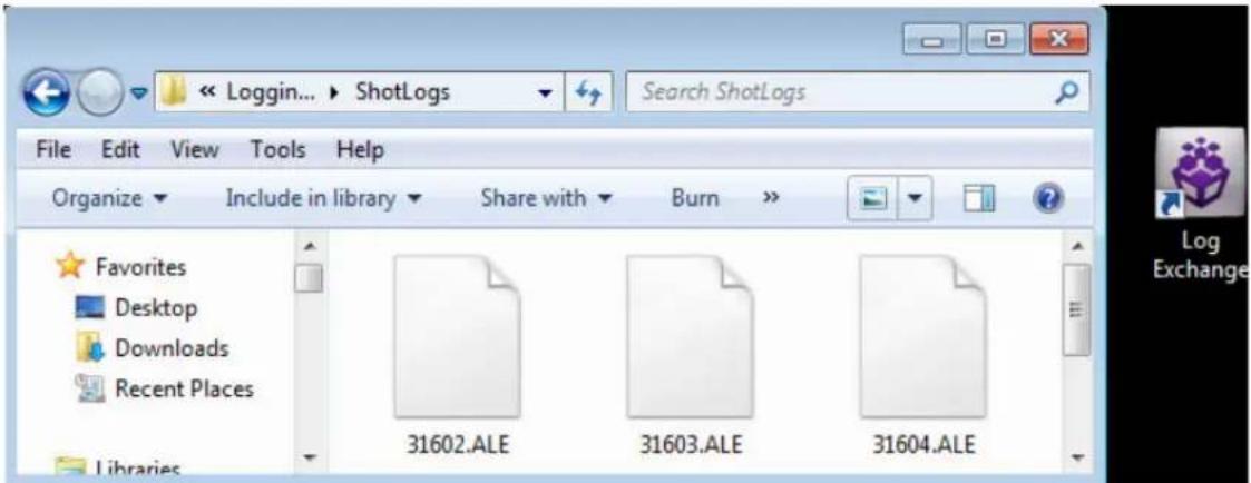
- Drag the selected files to the Shortcut icon, and release the mouse button.
- Depending on the type of files you convert, one of the following occurs:
- If the ALE utility recognizes the file type, a message box opens indicating the conversion was successful.
- If the file type is not recognized, the Select File Type dialog box opens. Select the type of file you convert and click OK.
- If the file type is an ALE file, the ALE Convert Type dialog box opens. Select a file type for the converted output file and click OK.
A message box opens, indicating the conversion was successful.
- Click OK to close the message box.
The converted files have the same file names as the original files, with an extension of the converted file format.
For example, the .ale file name extension is added for the Avid format. The converted files are stored in the folder containing the original log files.
Converting Log Files with Avid Log Exchange (Macintosh)
Use the ALE utility, included with your system, to convert shot logs that you create during a film-to-tape transfer.
To convert a log file to an ALE file:
- Select Go > Applications, open the ALE folder, and double-click the ALE icon. The Avid Log Exchange dialog box opens.

Avid Log Exchange dialog box
1 Files you can convert 5 Global Settings information
2 Files you can generate 6 Convert button
3 Clean and Relaxed options 7 Quit button
4 Track selection
- Select the type of file you want to convert from the Input list.
If you are not sure of the type of file, select the Automatic option. ALE will determine the type of file based on the file name.
For a list of supported file types, see Log Formats Compatible with Avid Log Exchange.
- Select the type of file you want to create from the Output list.
The default output selection is the Avid Log Exchange (.ale) format. This is the required format for import into an Avid bin.
- Select the tracks to include in the Tracks column of the log.
After you import the log into an Avid bin, the system captures all tracks shown in this column when you batch capture.
The Track selection only works on non ALE files that you convert to an ALE format. When ALE is the incoming format, Track selection does not work.
- Select the options Clean if you want ALE to clean the ALE output file to eliminate overlapping timecodes for clips.
When you select Clean, the utility changes the end timecode of a previous event to be less than that of the following event. Clean is the default.
- When you select Clean, you can also select Options > Relaxed to prevent the deleting of events that come earlier in the transfer. Relaxed is not set by default.
For example, if you transfer film footage with a timecode of 2:00:00:00 and then add clips at the end with a timecode of 1:00:00:00, Relaxed prevents the deleting of events that come earlier in the transfer. This occurs when you shoot footage across the midnight hour, the first half of the film has 24 hours, and the second half has 0 hours.
- Select the global settings information, for example, NTSC or PAL, that you want to appear in the ALE file.
Global settings appear at the top of the .ale file.
-
Click the Convert button to open the Select File To Convert dialog box.
-
Open the drive and folder that contain the files you want to convert.
-
Double-click the input file name.
If you select a file type, ALE converts the file immediately.
If you select the Automatic option, a message box opens and asks you to confirm the file type.
- Click the button for the selected file type.
A message box opens.
- Do one of the following:
Click This File Only button to convert only the file you select to the format you select.
Click All Files button to convert all files you select in this session to the format you select. If you click All Files, the message boxes does not open the next time you open a file.
ALE stores the converted file in the same folder as the original input file.
The system adds the replaces the original file name extension by the extension for the new format. You can only import .ale files into Avid products.
Using Drag-and-Drop Conversion for Log Files (Macintosh)
Use this shortcut to convert files into an ALE file.

If the log file is a Final Cut Pro, Cinema Tools, or a Tab Delimited shot log file, you cannot use drag-and-drop conversion. Use the procedure in “Converting Log Files with Avid Log Exchange (Macintosh)” on page 122) to convert files of this type.
To convert a log file by using drag-and-drop conversion:
- Check the options that are set in the ALE utility.
See “Converting Log Files with Avid Log Exchange (Macintosh)” on page 122. - Navigate to and then open the folder that contains the Avid Log Exchange icon.
- Open the folder that contains the files you want to convert, positioning the folder so the Avid Log Exchange icon is visible.
- Select the files you want to convert.
- Drag the selected files to the Avid Log Exchange icon, and release the mouse button.
The system converts the files to Avid format and adds the .ale file name extension to the new file names.
Viewing ASC Color Decision List (CDL) Parameters in Avid Log Exchange
Avid Log Exchange can store ASC_SOP (American Society of Cinematographers Slope, Offset and Power) and ASC_SAT (American Society of Cinematographers Saturation) parameters.
To view the ASC\_SOP and ASC\_SAT parameters in your Avid editing application:
- With a bin in Text view, select Bin > Headings.
- Click to select ASC_SOP and ASC_SAT.
- Import the ALE file.
The ASC_SOP and ASC_SAT information appears in the appropriate bin column.
To view the ASC\_SOP and ASC\_SAT parameters in the EDL application:
- With the sequence loaded in the Avid editing system, select Output > EDL.
- In EDL Manager, select Windows > Options.
- Select the Comments tab.
- Enable the Color Decision List option.
- Select File > Get Current Sequence.
The ASC_SOP and ASC_SAT information appears as part of the edit event.
Log Formats Compatible with Avid Log Exchange
The table lists the log formats that you can import directly or convert for import when you use Avid Log Exchange (ALE).
Log Format Requirements File Name Extension
| AatonBase Conversion required .atn or .atl | |
| Avid Log Import directly .ale | |
| Cinema Tools Conversion required .txt | |
| CMX EDL Conversion required .cmx | |
| Evertz® | Conversion required .ftl |
| Excalibur Conversion required .ale or .flx | |
| Final Cut Pro Conversion required .txt | |
| FLEXTM | Conversion required .flx |
| Keyscope Conversion required .ksl | |
| Log ProducerTM | Conversion required .llp |
| Log right | Import directly .ale |
| OSC/R (Macintosh® only) | Conversion required .asc |
| OLE (Windows only) | Conversion required .odb |
| Shotlister | Import directly .ale |
| Tab Delimited | Conversion required .txt |
Avid Log Specifications
Use a word processing application or a text editor to prepare an Avid log on any Windows or Macintosh computer You can use the file name extension .txt, but it is not required.
To ensure accuracy, you must follow the Avid log specifications described in this section.
An Avid log is composed of three sections, in this order:
- Global Titles
- Standard and custom column Titles
- Data Titles
When you create an Avid log, you must follow the order precisely. The tables in these topics follow this order.
The tables use the following conventions:
- A Title appears in the first column, without angled brackets or square brackets. For example, FIELD_DELIM is the first global Title.
- A
is surrounded by angled brackets. appear underneath, also in angled brackets. You must enter one of these values. For example, <29.97> is one of the supported values for the FPS Title; to specify that value, type 29.97. - A
is also surrounded by angled brackets, but it is italicized. For example, is the data entry for the Start Title; type the correct timecode, in the format 08:19:10:00 (or 08:19:10:00, for drop-frame timecode). - [Tab] and [Enter] (Windows) or [Return] (Macintosh) keys are surrounded by standard brackets.
- A column contains the word “Required” if the Title must be included in the log.
- The final column contains notes about the Title or values.
You can decide not to display a defined Title (including a required Title), except for Name. Name must always be displayed.
The maximum number of combined global, standard, and custom Titles in a log file is 64.
For an example of a simple log file, see “Sample Avid Log” on page 134.
Global Titles
The global Titles must come first in an Avid log file, and you must enter one value for each Title.
GLOBAL Titles: Global Titles are case sensitive and must be spelled exactly as shown. Include all required Titles. Other Titles are optional but might be necessary for your project. The maximum number of combined global, standard, and custom Titles in a log file is 64.
Title [Enter] or
[Return]
Required This marks the start of the global Titles.
| FIELD_DELIM [Tab] <TABS> [Enter] or | [Return] | Required Enter TABS to show that the file is Tab delimited. | |
| VIDEO_FORMAT [Tab] <NTSC> <PAL> | [Enter] or [Return] | Required | |
| FILM_FORMAT [Tab] <16mm> <35mm,3perf> <35mm,4perf> | [Enter] or [Return] | ||
| AUDIO_FORMAT [Tab] <22kHz> <24kHz> <44kHz> <48kHz> | [Enter] or [Return] | Audio sampling rate for catpure.You can override this for individual clips. | |
| TAPE [Tab] <tape name> [Enter] or | [Return] | Required Name of the videotape reel you log. If you omit this Title, the file name becomes the global tape name. You can override this for individual clips. | |
| FPS [Tab] <23.98> | <24> <25> <29.97> | [Enter] or [Return] | Required Capture rate is 23.98 fps(23.978 fps) for NTSC, 24 fps for NTSC or PAL, 25 fps for PAL, or 29.97 fps for NTSC. |
| [Enter] or [Return] | Press Enter (Windows) or Return (Macintosh) a second time after you enter the FPS value. This marks the end of the global Titles. | ||
Column Titles
The standard column Titles appear after the global Titles in the Avid log file.
You do not enter the data for a column Title along with the Title. You enter the data later, in a separate data section.
You must include the five required standard column Titles; they are listed first in the table.
You can create your own custom column Titles. Enter them after the standard Titles (see the last Title in the table). To create a custom Title, substitute the custom Title name for
COLUMN Titles: Column Titles are case sensitive and must be spelled exactly as shown. Note that the first five Titles are required. Other Titles are optional but might be necessary for your project. This table lists only the column Titles that are relevant to shot log files. Some data, such as Creation Date, is gathered by the system. The table does not include Titles for such data. The maximum number of combined global, standard, and custom Titles in a log file is 64.
Column [Enter] or [Return] Required Indicates the start of the column Titles.
Name [Tab] Required Title for clip name.
Tracks [Tab] Required Title for tracks you select for capture.
Start [Tab] Required Title for video timecode of sync point — the
timecode IN for clip. From address track of video.
End [Tab] Required Title for timecode OUT for clip. From
address track of video.
Audio [Tab] Title for the audio resolution (sample rate). If
omitted, the global entry for AUDIO_FORMAT applies.
Auxiliary Ink [Tab] Title for a second ink number used for the
clip.
Auxiliary TC1 [Tab] Title for auxiliary timecode.
Auxiliary TC2 [Tab] Title for auxiliary timecode.
Auxiliary TC3 [Tab] Title for auxiliary timecode.
Auxiliary TC4 [Tab] Title for auxiliary timecode.
Auxiliary TC5 [Tab] Title for auxiliary timecode.
Camera [Tab] Title for the camera used to film this clip.
This feature is used in multicamera shoots.
Camroll [Tab] Title for the camera roll ID containing this
clip.
Duration [Tab] Title for timecode Start to timecode End, the
length of the video clip.
FPS [Tab] Title for video frames per second rate for
capturing the individual clip. If omitted, the global entry applies.
Film TC [Tab] Title for the timecode used on the film.
Ink Number [Tab] Title for the ink number used for the clip.
KN Duration [Tab] Title for the length of the clip, expressed in
feet and frames.
KN End [Tab] Title for the ending key number for the clip.
KN Start [Tab] Title for the starting key number for the clip.
Labroll [Tab] Title for the lab roll ID for the clip. Lab rolls
are a combination of several camera rolls.
Perf [Tab] Title for the film-edge perforations format
used for 3-perf projects.
Pullin [Tab] Title for the telecine pulldown of the first
frame of the clip (pulldown phase). Pullin can have the values A, B, C, or D.
Pullout [Tab] Title for the telecine pulldown of the last
frame of the clip (pulldown phase). Pullout can have the values A, B, C, or D.
Reel # [Tab] Title for the source reel number.
Scene [Tab] Title for the scene number of the clip.
Shoot date [Tab] Title for the date the footage was shot.
Sound TC [Tab] Title for Nagra timecode, Arri® code, and so
on, at the sync point. Syncs with the Start timecode. Required if tracking the sync sound. Capture rate can be 25 or 30 fps.
Soundroll [Tab] Title for sound roll ID for clip.
TC 24 [Tab] Title for 24-fps timecode.
TC 25P [Tab] Title for 25-fps timecode with pulldown.
TC 25 [Tab] Title for 25-fps timecode.
TC 30 [Tab] Title for 30-fps timecode.
Take [Tab] Title for take ID for clip.
Tape [Tab] Title for source tape ID for the individual clip.
If omitted, the global entry applies.
DESCRIPT [Tab] Title for description of clip.
COMMENTS [Tab] Title for comments about clip.
Add any category of information you want. Add as many Titles as you want, but do not use more than a total of 64 global and column Titles in the file. Press the Tab key between each Title. Do not press the Tab key after the last Title.
[Enter] or [Return] [Enter] or [Return] Press [Enter] (Windows) or [Return]
(Macintosh) twice (do not press Tab) after the last Title.
Data Entries
The data entries come after the Custom column Titles. The table shows the format for entering data. Enter a line of data in this format for every clip. Be sure to start the data section for each clip with the word Data [Enter] (Windows) or Data [Return] (Macintosh).
DATA Titles: The word Data marks the start of the data for each clip.
Data [Enter] or Required Enter the word Data to mark the start of the logged clip entries. [Return]
DATA FOR EACH CLIP: Enter a line of data for each clip. Enter the data so it aligns with its column Title. (The data that goes with the ninth column Title must be the ninth data entry.) Be sure to enter data for all the required values. To leave a data position unfilled, press the Tab key instead of typing data. Press Enter (Windows) or Return (Macintosh) at the end of each line. Your Avid system supports up to four audio tracks in imported and exported logs.
| [Tab] | Required | Under End Title. Enter the video timecode for the last frame of the clip. | |
| <22kHz> | [Tab] | Under Audio Title. | Enter the audio sampling rate for this clip only. |
| <24kHz> | If omitted, global entry applies. | ||
| <44kHz> | |||
| <48kHz> | |||
| [Tab] | Under Auxiliary Ink Number Title. Identify a second ink number for the start of the clip. | ||
| [Tab] | Under Auxiliary TC Title. Enter a Nagra timecode, Arri code, and so on, for the sync point. Syncs with the Start timecode. | ||
| [Tab] | Under Camera Title. Identify the camera, using letters or numbers. For multicamera shoots. | ||
| [Tab] | Under Camroll Title. Identify the camera roll, using letters and numbers. | ||
| [Tab] | Under Duration Title. Enter the length of the video clip, Start to End. | ||
| <23.98> | [Tab] | Under FPS Title. | Enter the video capture rate for this clip only. If omitted, the global entry applies. Use 23.98 fps (23.978 fps) for NTSC, 24 fps for NTSC or PAL, 25 fps for PAL, or 29.97 fps for NTSC. |
| <24> | |||
| <25> | |||
| <29.97> | |||
| [Tab] | Under Film TC Title. Identify the timecode used for the film, usually at 24 fps. | ||
| [Tab] | Under Ink Number Title. Identify the ink number for the start of the clip. | ||
| [Tab] | Under KN Start Title. Identify the complete key number for the start of the clip, for example, KU 31 2636-8903&12. | ||
| [Tab] | Under KN End Title. Identify the key number for the end of the clip. Identify only feet and frames, for example, 0342&07. | ||
| [Tab] | Under KN Duration Title. Identify the length of the clip, in feet and frames. | ||
| [Tab] | Under Labroll Title. Identify the lab roll, use letters and numbers. | ||
| <1> | [Tab] | Under Perf Title. | Edit the perf for this clip only. |
| <2> | |||
| <3> |
| [Tab] Under Pullin Title. Identify the telecine pulldown of the first frame of the clip (pulldown phase). NTSC only. | ||
| (matchback only) | ||
| [Tab] Under Pullout Title. Identify the telecine pulldown of the last frame of the clip. NTSC only. | ||
| (matchback only) | ||
| [Tab] | Under Reel # Title. Identify the reel, use numbers. | |
| [Tab] | Under Scene Title. Identify the scene, use letters and numbers. | |
| [Tab] | Under Shoot Date Title. Identify the date the footage was shot, use numbers or letters and numbers. | |
| [Tab] | Under Sound TC Title. Identify the sound timecode at the sync point. Syncs with the Start timecode. | |
| [Tab] | Under Soundroll Title. Identify the sound roll, use letters and numbers. | |
| [Tab] | Under TC 24 Title. Identify the start of the clip for 24p timecode. | |
| [Tab] | Under TC 25p Title. Identify the start of the clip for 25p timecode (PAL pulldown). | |
| [Tab] | Under TC 25 Title. Identify the start of the clip for 25-fps timecode (PAL). | |
| [Tab] | Under TC 30 Title. Identify the start of the clip for 30-fps timecode. | |
| [Tab] | Under Take Title. Identify the take, use letters and numbers. | |
| [Tab] | Under Tape Title. Enter the source videotape ID for this clip only. | |
| [Tab] | Under DESCRIPT Title. Describe the clip. | |
| [Tab] | Under COMMENTS Title. Comment on the clip. | |
| [Tab] | Under the Titles you create, type the appropriate information. | |
| [Enter] or [Return] | Press Enter (Windows) or Return (Macintosh) after the last entry for the clip.Do not press Tab after the last entry for the clip. | |
Enter an additional line of data for each remaining clip.
Sample Avid Log
This is a sample Avid log for an NTSC video project.
Formatting keys (such as [Tab] and [Enter] (Windows) or [Return] (Macintosh)) display in brackets.
Heading [Enter]
FIELD_DELIM [Tab] TABS [Enter]
VIDEO_FORMAT [Tab] NTSC [Enter]
AUDIO_FORMAT [Tab] 44kHz [Enter]
TAPE [Tab] 001 [Enter]
FPS [Tab] 29.97 [Enter]
[Enter]
Column [Enter]
Name [Tab] Tracks [Tab] Start [Tab] End [Enter]
[Enter]
Data [Enter]
CU Josh & Mary [Tab] V [Tab] 01:00:00:00 [Tab] 01:15:05:00 [Enter]
CU Josh [Tab] VA1 [Tab] 01:15:06:00 [Tab] 01:20:00:00 [Enter]
Sample Avid log (Windows)
Heading [Return]
FIELD_DELIM [Tab] TABS [Return]
VIDEO_FORMAT [Tab] NTSC [Return]
AUDIO_FORMAT [Tab] 44kHz [Return]
TAPE [Tab] 001 [Return]
FPS [Tab] 29.97 [Return]
[Return]
Column [Return]
Name [Tab] Tracks [Tab] Start [Tab] End [Return]
[Return]
Data [Return]
CU Josh & Mary [Tab] V [Tab] 01:00:00:00 [Tab] 01:15:05:00 [Return]
CU Josh [Tab] VA1 [Tab] 01:15:06:00 [Tab] 01:20:00:00 [Return]
Sample Avid log (Macintosh)
Creating an Avid Log
You can use any word processing application or text editor to create Avid logs. However, you must save the file as a text document (ASCII format).
When log manually, you should do the following:
- Identify the source tape for each shot.
- Document each clip's name, start timecode, and end timecode.
- For NTSC transfer tapes for film projects, you must supply pulldown information in the Pullin column of the bin before you capture.
This is the minimum information required to capture successfully. You can also add other information such as comments, auxiliary timecodes, or key numbers for film projects. You can make a separate log file for each videotape, or log clips from several different videotapes in one log.
Windows systems ship with a text editor called WordPad. Mac OS ^® X systems ship with a text editor called TextEdit.
To open WordPad:
▶Click the Start button, and select All Programs > Accessories > WordPad.
To open Text Edit:
▶Select Go > Applications, and double-click TextEdit.
To create a text document in TextEdit:
▶Select Format > Make Plain Text.
To create an Avid Log by using a word processor or text editor:
- Enter shot log information according to the specifications described in “Avid Log Specifications” on page 126.
- Save your file as a text file in the Save As dialog box.
You can use the file name extension .txt, but it is not required.

Your Avid editing application only accepts text files (ASCII format).
After you double-check the log, import it into your Avid editing application. For more information, see “Importing Shot Log Files” on page 160.
Double-Checking Log Files
When you import shot logs for video, your Avid editing application compares the video duration to the video out minus the video in. When you import film shot logs, the system compares the key number out minus the key number in.
If the system detects a discrepancy, it reports the error to the Console and does not bring the clip into the bin. The best way to ensure that the system does not discard clips on import is to double-check the logs for discrepancies in duration and marks.

Select Tools > Console to open the Console window. For more information, see “Using The Console Window” on page 115.
Transferring Bins from MediaLog
The MediaLog program is a standalone application that speeds the process to create and import log information from a Windows or Macintosh computer. MediaLog mirrors the Avid editing interface when you create projects, bins, and clip information in the bin, and includes serial deck control to log directly from tape.

For information on specific MediaLog procedures, see the Avid MediaLog Help.
If you log your source footage with MediaLog, you can transfer the bins directly to your Avid editing application to batch capture. You can also import the logs as described in “Importing Shot Log Files” on page 160.
To transfer bins from MediaLog:
- Save the MediaLog bins to a storage device or disk.
If you use MediaLog for Macintosh, make sure that your Windows system can mount the storage device or disk correctly. If your MediaLog folders are available through a server or other networked source, locate the MediaLog folder.
- Attach the storage device from MediaLog to the Avid editing system, or insert the disk into the Avid editing system.
- Quit your Avid editing application.
- Open the project folder in which you want to store the MediaLog bins.
This folder is located in the Avid Projects folder. For information about the location of the Avid Projects folder, see “Avid Projects and Avid Users Folders” on page 46.
- Navigate to the location on your storage device or network drive where you copied the bins you want to transfer.
- Select the bins in the storage device or network drive, and save them to the project folder on your Avid editing system.
To associate the transferred bins with your project:
- Restart your Avid editing application and open your project.
- Associate the imported bins with your project by doing the following:
a. Select File > Open Bin.
b. Use the Open Bin dialog box to locate the new bin.
c. Double-click the bin to open it within your project.
The new bin appears in the Bins list in the Project window.
The bins you import contain master clips only with no associated media files. Before you can view or use these clips, you must batch capturing the source material to create the associated media files. For information about batch capturing, see “Batch Capturing from Logged Clips” on page 239.
Logging Directly into a Bin
To log clips directly into a bin use the Capture tool in one of two ways:
- Log directly into a bin with an Avid-controlled deck for semiautomated data entry.
- Log manually during or after you view footage offline with a non-Avid-controlled deck or other source.
Before you capture, observe the following important guidelines for preroll, timecode formats, and naming of tapes when you log.
Logging Preroll
Leave adequate preroll with continuous timecode prior to IN points when you log your tapes. The recommended minimum preroll is 2 seconds for Betacam ^® playback, 5 seconds for 3/4-inch U-matic ^® playback, and 6 seconds for DV playback.

Use the Preroll menu in the Deck Settings dialog box to set the default preroll for tape playback. For more information, see “Deck Settings” on page 1373.
Logging Timecode
Within an NTSC project, check the timecode format of each tape (drop-frame versus non-drop-frame timecode) when you log without a tape in the deck. Log drop-frame timecode with semicolons (;) between the hours, minutes, seconds, and frames. Log non-drop-frame timecode with colons (:). You can set the timecode format to use in the Deck Preferences Settings dialog box. For more information, see “Deck Preferences Settings” on page 1374.

To change the logged timecode format, select Clip > Modify. For more information, see "Modifying Clip Information" on page 352.
Naming Tapes
When you enter tape names in the Capture tool, consider the following:
- Tape names must be alphanumeric characters (A to Z, 0 to 9). They can include uppercase and lowercase characters. The maximum length of a name is 32 characters.
- It is possible to have a single tape listed as several different tapes if you alter the case of the letters. For example, if you type a single name as TAPE, Tape, and tape on three different occasions, all three names appear. This can cause significant problems in keeping track of clips when you batch capture, recapture, and generate an EDL. Select a case convention and maintain it throughout a project.

If you want your Avid editing application to consider master clips as coming from the exact same tape, you should try to select that tape name from the Select Tape dialog box. If you do not see the tape, but know you have online media from that tape, you should click the Scan for Tapes button. For more information, see “Logging with Avid-Controlled Decks” on page 139.
- It is important that you create a naming scheme for your tapes. For example, you can easily sort and view tapes with similar names together in a bin. However, it can be difficult to distinguish among numerous tapes with similar names when you try to locate a specific tape quickly. Name tapes based upon the amount and complexity of your source material.

If you modify tape names and timecodes, it can affect any key numbers you enter for selected clips.
- If you plan to generate an edit decision list (EDL) to import into an edit controller for online editing, double-check the controller's specifications. Some edit controllers truncate source tape names to as few as six characters, while others eliminate characters and truncate to three numbers. Alterations like these at the EDL stage might cause the system to identify different source tapes with similar names, which could cause you to lose track of source material.
Logging with Avid-Controlled Decks
When you log with a compatible tape deck controlled from your Avid editing application, you can enter frame-accurate timecode information from the deck to automate part of the logging process. This method is more accurate than manual entry because you transfer timecodes directly from tape to the bin.

For information about connecting a compatible deck to your system, see “Connecting Cameras, Decks, and Monitors” in the Help.
To log clips directly into a bin from an Avid-controlled deck:
- Make sure the deck is properly connected and turned on.
- Open the bin where you want to store the clips.
- Select Tools > Capture.
The Capture tool opens. The Client monitor displays your video.

1 Capture/Log Mode button 6 Timecode display
2 Mark IN button 7 Deck controls
3 Channel Selection buttons 8 Deck Selection menu
4 Clip Name text box 9 Source Tape Display button
5 Clip Comment text box
If you forget to connect and turn on the power to the deck before you open the Capture tool, click the Deck Selection menu and select Check Decks to reinitialize the deck control.
- If the Capture tool is not in Log mode, click the Capture/Log Mode button until the LOG icon appears.
- Click the Deck Selection menu, and select a deck.
For more information, see "Selecting a Deck in the Capture Tool" on page 187.
- Insert your tape into the deck.
The Select Tape dialog box opens.
Select “Show other project’s tapes” to display the tape names and associated project names for all bins.

Select Tape dialog box. Top: New tape name button. Center: list of tapes. Bottom: Show other projects option.
Because the media file database does not open when you start your Avid editing application, tape names of all online media files do not appear automatically.
If the tape name does not appear in the Select Tape dialog box, click the Scan for Tapes button. The system displays tape and project names.
- Provide the system with a tape name in one of the following ways:
▶ Select the name of the tape from the list in the Select Tape dialog box and click OK.
▶ Click New if the tape is not in the list. A new tape name line appears in the dialog box. Type the new name and click OK.
The tape name displays in the Capture tool.
For guidelines to name tapes, see "Naming Tapes" on page 138.
A message that the system is waiting for you to mark an IN point displays in the message bar.
- Use one of the following methods to set either an IN point or an OUT point for the clip you want to log:
To keep the deck running while you log: Start the deck. At the point where you want to start the clip, click the Mark IN button or press the F4 key. The deck continues to play.
If you want to pause the deck while you enter a clip name and comments, see “Pausing the Deck While Logging” on page 143.
To cue your source tape: Use the deck controls in the Capture tool to cue your source tape to the start or end point. Click the Mark IN button or the Mark OUT button in the Capture tool.
Capture tool Mark IN button (left) and Mark OUT button (right)
To log using timecode: If the footage starts at an IN point or ends at an OUT point, type the timecode in the text box next to the Mark IN button or the Mark OUT button. Then press the Go to IN button or the Go to OUT button to scan the tape forward to the mark.

Capture tool Go to IN button (left) and Go to OUT button (right)
After you set the mark, the Mark IN button changes to the Mark OUT and Log button or the Mark IN and Log button, depending on the first mark you set.
Mark IN and Log button (left) and Mark OUT and Log button (right)

For NTSC film-to-tape transfer or footage downconverted from 1080p/24, you must log the correct pulldown phase. See “Setting the Pulldown Phase” on page 149 and “Entering Pulldown Information” on page 151.
-
(Option) Enter a clip name and comment in the corresponding text boxes in the Capture tool.
-
To finish logging the clip, do one of the following:
If the deck is running: Click the Mark OUT and Log button or press the F4 key. The clip logs into the bin and the deck continues to play.
To cue the remaining start or end point: Use the deck controls to locate the start or end point. Click the Mark OUT and Log button or the Mark IN and Log button to set the remaining IN point or OUT points. The clip logs into the bin.
To log using timecode: Type a timecode for the clip's IN point, OUT point, or duration in the timecode text boxes next to the corresponding icon. Then press the Go to IN button or the Go to OUT button to scan the tape forward to the mark. To log the clip into the bin, click the Log Clip button in the Capture tool.


Logging controls (left) and Log Clip button (right)
The clip name highlights in the bin. The system automatically names and numbers the clip, you can rename the clip.
- (Option) Type a new name in the highlighted area to rename the clip.
You can accept the clip name and proceed with the logging process and change the clip names in the bin at a later time.
- Repeat these steps until you log all your clips.
While you view the footage, you can continue to update your marks on-the-fly. Click the Mark IN button or the Mark OUT button repeatedly to enter the second mark.
Pausing the Deck While Logging
If the deck is playing while you log clips, you can direct your Avid editing application to pause the deck after you set an IN point and an OUT point. You can then enter the name and comment for the clip you want to log.
To pause the deck while logging:
- In the General tab of the Capture Settings dialog box, select the "Pause deck while logging" option.
- Set up your deck and the Capture tool as described in "Logging with Avid-Controlled Decks" on page 139.

- When you reach the point where you want to start the clip, click the Mark IN button in the Capture tool or press the F4 key. The Mark IN button changes to the Mark OUT button and the deck continues to play.

- When you reach the point where you want to end the clip, click the Mark OUT button in or press the F4 key again. The Mark OUT button changes to the Log Clip button, and the deck pauses.

- Type a clip name and comment in the corresponding text boxes in the Capture tool.
- Click the Log Clip button or press the F4 key.
Your Avid editing application logs the clip in a bin, and the deck starts playing again.
Using a Memory Mark When Logging
You can add a memory mark to a particular location on a tape, then use the Go to Memory button to move through the tape to the marked location.
To use a memory mark for a particular location on a tape:
▶ Click the Mark Memory button in the Capture tool to mark the location.
▶Click the Go to Memory button to move through the tape to the marked location.
▶Click the Clear Memory button to clear the memory mark.

Memory buttons: (right to left) Mark Memory, Go to Memory, Clear Memory
You can add one mark per tape. The memory mark is not stored on the tape. When you remove the tape from the deck and insert another tape into the deck, the mark clears.
Logging with Non-Avid-Controlled Decks
You can use the Capture tool to log clips directly into a bin from a source that is not controlled by your Avid editing application. For example, you can log clips from a deck that is not connected to the system, or from handwritten or printed log information for a tape that was previously logged but is not currently available.

For NTSC projects, when you log within the Capture tool, you should leave the deck empty. If a tape remains in the deck, the system determines drop-frame or non-drop-frame from that tape whether or not it matches your tape's timecode format.
To log clips directly into a bin from a non-Avid-controlled deck:
- If there is a deck connected to the system, eject the tape from the deck.
- Double-click Deck Preferences in the Settings list of the Project window.
The Deck Preferences dialog box opens. - For NTSC projects, click "When no tape in deck log as" menu, and select Non-Drop-Frame or Drop-Frame.
- Click OK to close the dialog box.
-
Open the bin where you want to store the clips.
-
Select Tools > Capture.
The Capture tool opens.

1 Capture/Log Mode button 8 Deck Selection menu
2 Channel Selection buttons 9 Source Tape Display button
3 Message bar 10 Mark Memory button
4 Clip Name text box 11 Go to Memory button
5 Clip Comment text box 12 Clear Memory button
6 Timecode display 13 Clear IN and OUT buttons
7 Deck controls 14 Mark IN and OUT buttons
- Click the Capture/Log Mode button until the LOG icon appears.

- Click the Source Tape Display button.
A dialog box opens.
-
Click Yes to open the Select Tape dialog box.
-
Double-click the name of the tape in the dialog box, or click New and enter the name of the tape.
- Click OK.
- Use the Channel Selection buttons to select the tracks you want to log.
- Type the start timecode in the Mark IN text box.
- (Option) Enter a clip name and comment in the corresponding text boxes.
- Type the end timecode in the Mark OUT text box.
For NTSC film-to-tape transfer or footage downconverted from 1080p/24, you must log the correct pulldown phase. See “Setting the Pulldown Phase” on page 149 and “Entering Pulldown Information” on page 151.
【
- Click the Log Clip button.
The clip name highlights in the bin. The system automatically names and numbers the clip, you can rename the clip.
- (Option) Type a new name in the highlighted area to rename the clip.
You can accept the clip name and proceed with the logging process and change the clip names in the bin at a later time.
- Repeat these steps until you have logged all your clips.
Understanding the Pulldown Phase
If you log or capture 24-fps sources (film-to-tape transfers, media downconverted from 1080p/24 footage, or both), you can set the pulldown-to-timecode relationship for a transferred tape in the Film and 24p Settings dialog box.
For information about the pulldown process, see “Transfer of 24-fps Film to NTSC Video” on page 1503.
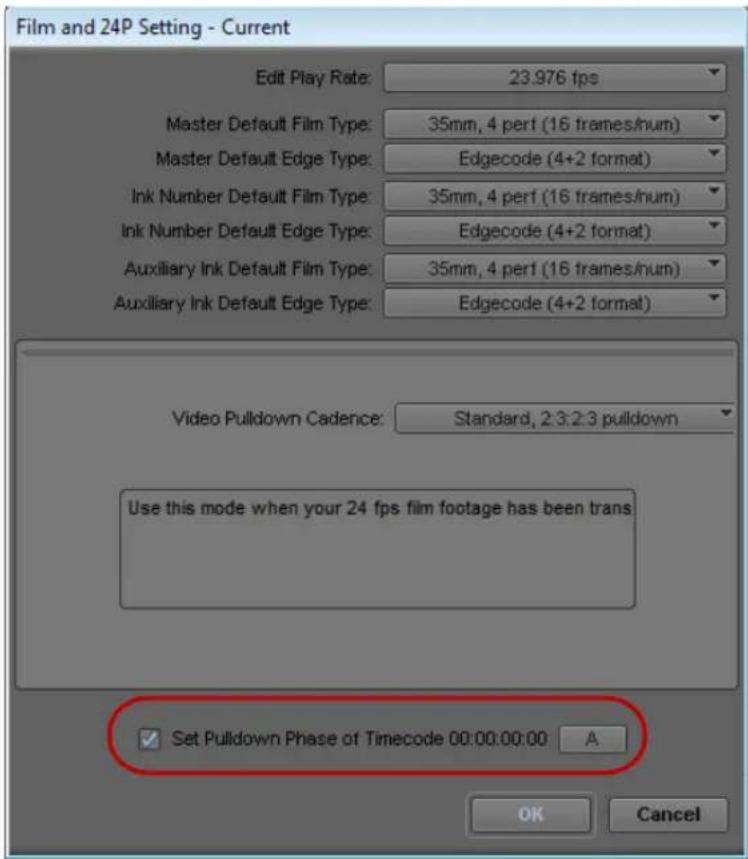
Set Pulldown Phase option in the Film and 24P Settings dialog box
You set this relationship when you select the pulldown phase (sometimes called the pulldown frame or pullin frame), which is the video frame at which the master clip starts. The pulldown phase is designated A, B, X, C, or D. Film labs and transfer houses typically use the A frame to start the transfer.
The illustration shows the relationship between film frames and video frames.

flowchart
graph TD
    A["Row A"] --> A1[".1"]
    A --> A2[".2"]
    B["Row B"] --> B1[".1"]
    B --> B2[".2"]
    B --> B3[".1"]
    C["Row C"] --> C1[".2"]
    C --> C2[".1"]
    C --> D1[".2"]
    D["Row D"] --> D2[".1"]
    D --> D3[".2"]
Relationship between four film frames (left) and five NTSC video frames (right). On the right, .1 indicates an odd field and .2 indicates an even field.

This setting is not available in matchback projects. However, you can modify the pulldown phase after you log it. See “Entering Pulldown Information” on page 151.
The Set Pulldown Phase setting lets you log, batch capture, and capture-on-the-fly more easily, because the correct pulldown phase of any IN point for a particular tape is automatically determined. Setting the correct pulldown phase prevents inaccuracies in cut lists and matchback EDLs. It also prevents incorrectly captured clips that stutter when you play it in 24p NTSC projects.
For example, if you set the pulldown phase of 00:00:00:00 as A (indicating that the A frame is located at timecodes ending in 0 or 5), any timecode you log calculates its pulldown phase based on the same sync point, regardless of where you set the IN point. If you use the Capture tool to log a clip that starts at 01:00:10:01, your Avid editing application automatically enters B in the Pullin column of the bin. If you capture on-the-fly starting at 01:00:10:01 (a B frame), the system begins to capture at the next A frame, in this case, 01:00:10:05.

The Set Pulldown Phase feature does not work if you capture from a mark IN.
The pulldown-to-timecode relationship might vary from tape to tape, or within the same tape, depending on how the footage was transferred. If you find that a tape requires a different pulldown phase, you can change the setting in the Film and 24p Setting dialog box, or use the Modify Pulldown Phase dialog box before you capture. See “Modifying the Pulldown Phase Before Capturing” on page 154.

For information about fixing an incorrectly logged sync point, see “Modifying the Pulldown Phase After Capturing” on page 275.
Setting the Pulldown Phase
To set the pulldown phase:
- Determine the correct pulldown phase for 00:00:00:00 in one of the following ways:
▶ If you capture film-to-tape transfers, check the transfer log.
▶If you capture tapes that have been downconverted from 1080p/24, check what pulldown frame was set for 00:00:00:00 on the deck that performed the conversion.
If you still cannot determine the pulldown phase, see “Determining the Pulldown Phase” on page 152.
- Double-click Film and 24p in the Settings list of the Project window.
- Select Set Pulldown Phase of Timecode 00:00:00:00 and then click the menu, and select the correct pulldown phase (A, B, X, C, D).
- Click OK.
Film-Related Log Information
Once you enter or import the basic log information into a bin, you might want to add film-related log information before you capture.
The following are some important requirements for film-based projects:
- The minimum information required for capturing is the data recorded in the Start and End video timecode columns, and the pulldown phase for NTSC transfers, which is noted in the Pullin column (24-fps capture only).
- You can log each reel of film as a separate clip, which corresponds to a single master clip, only if the video transfer of the film reel has continuous pulldown (NTSC format), and continuous timecode (NTSC and PAL). If the film reels for your project do not meet this condition, then you must log each take on a reel of film as a separate clip, which corresponds to a single master clip.
If you log each reel as a separate clip, you can use the F1 and F2 keys to create subclips for each take. See “Creating Subclips While Capturing” on page 257.
- If you want to produce a cut list, or use film-tape-film-tape to recapture, you must log key numbers. You can add key numbers after you capture, before you create the cut list.
- All film and video reference numbers must be in ascending order.
- Continue to log additional film data into the Labroll, Camroll, Soundroll, Scene, and Take columns, or into your own custom columns, as necessary. You can include the information in these columns on the cut lists you create for your edited sequence.
Displaying Film Columns
To display film columns in the bin:
- Click the Bin View menu at the bottom of the Bin window, and select Film to display all the required film column Titles.

Location of the Bin View menu
- To log data under optional Titles (such as Ink Number, Auxiliary TC1-Auxiliary TC5, or Film TC), do the following:
a. Select Bin > Choose Columns.
The Bin Column Selection dialog box opens.
b. Ctrl+click (Windows) or Command+click (Macintosh) the specific Titles you want to add.
c. Click OK.
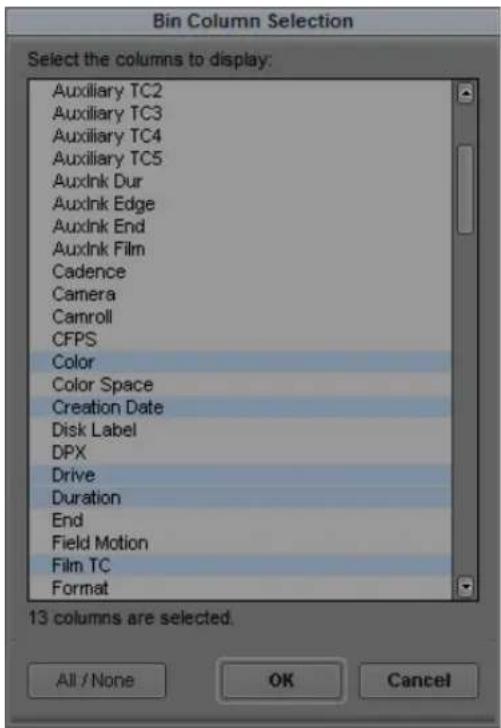
- Create a custom Title to track custom information for the job. To create a new Title, type a name that describes the information in the Titles bar at the top of the bin.
For more information on customizing bin views, see “Saving a Custom Bin View” on page 329.
Entering Pulldown Information
To accurately capture NTSC transfer tapes in 24p projects, you need to enter pulldown information into the bin. (This information is not required for PAL transfer tapes.) Setting the correct pulldown phase prevents inaccuracies in cut lists and matchback EDLs. If you import a log generated during the telecine transfer, the pulldown information is automatically included in the bin.

To import a log file, see "Setting the Pulldown Phase" on page 149.
If you do not have a transfer log, or if the transfer log is incorrect, you need to add the information manually. If you use the Capture tool to log clips, your Avid editing application uses the A frame as the default pulldown phase. You might need to edit this value.

For 24p projects, you can set a default pulldown phase in the Film and 24p Settings dialog box. See “Setting the Pulldown Phase” on page 149 (24p projects only).
For matchback projects, you need to log key-number information before you can log pulldown information.
If you specify the pulldown phase in the Pullin column, you accomplish the following:
- You ensure that clips start with the correct frame for the pulldown. Otherwise, you might experience inaccuracies in key-number tracking and in the cut lists.
- You indicate where the pulldown fields are located so your Avid editing application can accurately eliminate the pulldown fields during capture. This leaves you with a frame-to-frame correspondence between your digital media and the original 24-fps footage (24p projects only).
To do this, you must indicate whether the sync point at the start of each film clip transferred to tape is an A, B, C, or D frame, as described in “Determining the Pulldown Phase” on page 152 and “Modifying the Pulldown Phase Before Capturing” on page 154.
In most cases, the sync point is the A frame.

Start timecode column (left) and Pullin column (right) in the bin
Determining the Pulldown Phase
It is easiest to determine the pulldown of a sync point (or pulldown phase) if you ask your film lab to keypunch (cut a small hole in) the sync frame at the zero frame in the original film footage before you transfer the film to video. Many film labs or transfer houses can also provide a pulldown frame indicator which displays at the far right of the burn-in key numbers, depending on the equipment available. The A-frame pulldown coincides with timecode ending in 0 and 5 (:00, :05, :10, and so on).
If you have not keypunched your footage, you can determine pulldown according to clapsticks or any other distinctive frame at the beginning of the clip. It is easier to determine the pulldown if the frames depict motion.

For instructions on how to modify the pulldown phase, see “Modifying the Pulldown Phase After Capturing” on page 275.
To determine the pulldown phase:
- While you view the video transfer on a monitor, go to the keypunched (or clapsticks) sync point for the beginning frame of the clip you logged.
- Use the step wheel on the tape deck to step (jog) past the sync point frame field-by-field.
You will see either two or three keypunched fields. If the footage is not keypunched, look for two or three fields with little or no motion.
-
If there are two fields, the pulldown is either A or C. Step through the fields again, and note where the timecode changes:
-
If the timecode does not change from the first to the second field, the fields came from an A frame.
- If the timecode changes from the first to the second field, the fields came from a C frame.
The illustration shows a keypunch on the A frame. Notice where the timecode changes.

flowchart
graph TD
    A["Panel A"] --> A1[".1"]
    A --> A2[".2"]
    B["Panel B"] --> B1[".1"]
    B --> B2[".2"]
    B --> B3[".1"]
    C["Panel C"] --> C1[".2"]
    C --> C2[".1"]
    C --> D1[".2"]
    D1 --> D2[".1"]
    D2 --> D3[".2"]
    D3 --> D
    A1 --> A
    A2 --> A
    B1 --> B
    B2 --> B
    B3 --> B
    C1 --> C
    C2 --> C
    D1 --> D
    D2 --> D
    D3 --> D
Determining pulldown for keypunched footage. Red lines indicate the location of timecode changes.
- If there are three keypunched fields, or fields without motion, the pulldown is either B or D. Step through the fields again and note where the timecode changes:
- If the timecode changes from the second to the third field, the fields came from a B frame.
- If the timecode changes from the first to the second field, the fields came from a D frame.
- Enter or edit the information in the Pullin column in the appropriate bin, as described in "Modifying the Pulldown Phase Before Capturing" on page 154.
Modifying the Pulldown Phase Before Capturing
After you determine the correct pulldown phase (as described in “Determining the Pulldown Phase” on page 152) you can modify the pulldown phase before you capture in one of the following ways.
To modify the pulldown phase directly in the Pullin column:
- In the Bin, click the Text tab to display all bin information.
- Click the cell you want to modify.
- Click the cell again.
The pointer changes to an I-beam. - Type the pulldown phase and press Enter (Windows) or Return (Macintosh).
To modify the pulldown phase for multiple clips:
- Ctrl+click (Windows) or Command+click (Macintosh) the clips you want to modify.
- Select Clip > Modify.
- Click the Modify Options menu, and select Set Pull-in.
- Select A, B, C, or D.
- Click OK.
The pullin for all selected clips changes, based on the pulldown phase you select.
To modify the pulldown phase for multiple clips that have the same pulldown-to-timecode relationship:
- Ctrl+click (Windows) or Command+click (Macintosh) the clips you want to modify.
- Select Clip > Modify Pulldown Phase.
The Modify Pulldown Phase dialog box opens.
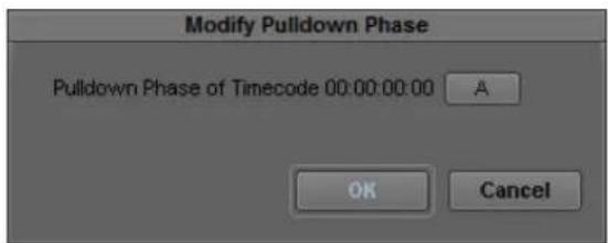
- Click the menu, and select the correct pulldown phase for timecodes ending in 0 or 5.
- Click OK.
The pulldown phase for each selected clip changes, based on the pulldown phase you select for 00:00:00:00.
The Pulldown Phase setting also appears in the Film and 24p Settings dialog box (24p projects only). You can override that setting with the Modify Pulldown Phase dialog box. The selection in the Film and 24p Settings dialog box remains the same. For more information, see “Setting the Pulldown Phase” on page 149.

If you want to modify the pulldown phase after you capture, you must first unlink the clips. See “Modifying the Pulldown Phase After Capturing” on page 275.
After you capture an NTSC transfer, the timecode shows a loss of every fifth frame of video. For example, if you find that your timecode jumps at one point from 1:00:14:15 to 1:00:14:17, you haven't lost a frame, just an extra pulldown field.
Entering Frames-per-Second Rates for PAL Transfers
When you log in advance for PAL film-to-tape transfers, you must log the footage as clips that have a 25-fps play rate, as listed in the FPS column of the bin. You can capture the footage on-the-fly, without logging the clips first. The minimum information required to capture the footage is the data logged in the Start and End video timecode columns.
Entering Key Numbers
You can enter your own custom key numbers for all clips (including captured, imported, and file-based clips) in the KN Start column in the bin.
To add key numbers:
▶ Highlight the KN Start column. Use one of the following formats and type the key number for the sync point at the start of the clip:
- K e ^TM yForknat: Type a two-character manufacturer and film-type code, a six-digit prefix for identifying the film roll, a four-digit footage count, a two-digit frame offset, and then press Enter (Windows) or Return (Macintosh).
Your Avid editing application adds a space, hyphen, and either a plus sign (for 35mm projects) or an ampersand (for 16mm projects) to format the number. For example, in a 35mm project, to enter KJ 23 6892-1234+15, type KJ236892123415. In a 16mm project, if you type the same number results in the code KJ 23 6892-1234&15.
- Other Formats: Enter other key-number formats in the Ink Number column. Type up to eight characters for the prefix, up to five characters for the footage count, two digits as the frame count, and then press Enter (Windows) or Return (Macintosh).
The Avid editing application automatically calculates the ending key number (KN End), based on the timecode duration.

Make sure the correct number appears when you press Enter (Windows) or Return (Macintosh). For key-number formats other than Keykode, you might need to type the space, hyphen (-), and plus sign (+) or ampersand (&) to format the number correctly.

Modifying tape names and timecodes affect any key numbers you enter for the selected clips.
Entering Additional Timecodes
You can enter custom timecodes for all clips (including captured, imported, and file-based clips) in the Auxiliary TC and Sound TC columns in the bin.
To enter additional timecodes:
- In one of the Aux TC columns (Aux TC1 through Aux TC5), type an auxiliary timecode that syncs with the video timecode logged in the Start column.
You can enter up to five auxiliary timecodes. Supported timecodes depend on your project: 30-fps for NTSC (drop-frame or non-drop-frame) and 25-fps for PAL. Use one of the following formats:
Enter a two-digit format for hours, minutes, seconds, and frames. You do not need to enter a leading zero. (For example, to enter 01:23:02:00, type 1230200.)
When you work with drop-frame timecode in the NTSC format, enter a semicolon to indicate drop-frame timecode (for example, to enter 01;23;02;00, type 01;230200).
- In the Sound TC column, enter the Nagra or DAT timecode for the original audio for the start of the clip.
The timecode should sync with the video timecode logged in the Start column in the bin.
- Enter the source sound-roll identifier in the Soundroll column.
Supported timecodes depend on your project: 30-fps for NTSC (drop-frame or non-drop-frame) and 25-fps for PAL. The clip you capture must contain an audio track.
- In the Film TC column, enter timecode generated by a film camera (using Aaton or Arri timecode) for tracking the picture at the start of the clip.
The film timecode should sync with the video timecode logged in the Start column. Avid supports only 24-fps timecode. The clip you capture must contain a video track.
- In the TC24 column, enter timecode for original HDTV sources (1080p/24) or audio DATs created for PAL feature film productions that use in-camera timecode.

You can use the Duplicate command to convert timecodes from one format to another. For more information, see “Duplicating Bin Columns with Timecode Information” on page 347.
Entering Ink Numbers
To enter ink numbers:
- In the Project window, click the Settings tab.
- Double-click Film and 24p.
The Film and 24p Settings dialog box opens.
- Make sure the correct options are selected for ink number format and ink number display, and click OK.
You can log different ink number formats in the same project as long as you change the ink number setting to the appropriate format before you log each type. Changing the ink number setting affects only the next ink numbers you log, not numbers you already logged.
- Return to the bin and enter numbers under the Ink Number Title.
For example, use Keykode format or use a two-digit prefix to identify the roll, a hyphen, a four- or five-digit footage count, a plus sign, and a two-digit frame count (for example, AA-00924+00).
Exporting Shot Log Files
You can export a shot log file from your Avid editing application in one of two formats to make adjustments in a text editor or to import into another system.
To export a shot log based on clip information in a bin:
- Open the bin which contains the clips you want to export. If necessary, click the Text tab to display all clip information.
- Click a Clip icon to select it.
- Ctrl+click (Windows) or Command+click (Macintosh) each additional clip you want to export.
- Select File > Export.
The Export As dialog box (Windows) or Destination dialog box (Macintosh) opens with a default file name in the File name text box (Windows) or Export As text box (Macintosh), based on the file type.
- Do one of the following to select the Export setting:
If you previously created an Export setting for exporting shot log files, click the Export menu, and select the setting. Then, go to step 10.
For information on creating Export settings, see “Customizing Export Settings” on page 1018.
▶If you want to review or edit Export settings, go to step 6.
- Click Options.
The Export Settings dialog box opens.
- Click the Export As menu, and select one of the following:
Select Avid Log Exchange to export the selected bin as a shot log file that complies with ALE specifications. For information about Avid Log Exchange, see “Using Avid Log Exchange to Prepare Log Files for Import” on page 118.
▶Select Tab Delimited to export the selected bin as a tab-delimited ASCII text file.
ALE and tab-delimited files include information for master clips and subclips only. Information for other objects, such as group clips, sequences, and precomputes, is not included.
- To modify an existing setting, select Save.
- To save the setting with a new name, select Save As and type a name in the dialog box that opens.
The system adds the Export Setting name to the list of formats available from the Export dialog box.
- Click Save to close the Export As dialog box (Windows) or the Destination dialog box (Macintosh).
- (Option) Change the file name. In most cases, keep the default file name extension.
- Select the destination folder for the file and click Save.
The file exports and appears at the selected destination.
To export an entire bin:
- Ctrl+click selected clips to deselect them, so that nothing is selected in the bin.
- Select File > Export.
The Export Bin As dialog box opens.
- Click the Export Bin As menu, select the appropriate option, and click OK.
The system creates a shot log of only the master clips in the bin.
6 Preparing for Capture
The chapter provides information on preparing your Avid editing application and your capture hardware before you capture media.
- Logging and Shot Logs
- Importing Shot Log Files
• Preparing the Hardware for Capture - Selecting Settings for Capture
- Configuring Decks
- Connecting a DV Device
- Setting Up the Capture Tool
• Preparing to Capture Audio
• Preparing to Capture Video
• Capture Preparations Check List
Logging and Shot Logs
Logging is the process of entering information about source material into bins at the beginning of the editing workflow. A shot log is a text file that lists information about a roll of film or a videotape, usually in chronological order.
You can get information into your bins either by importing a shot log file or by entering the information directly. You can log automatically or manually, either before capturing or while capturing.
Logging provides your Avid editing application with frame-accurate clip information (such as starting and ending timecodes). Your Avid editing application uses this information to capture the source footage and as the foundation for organizing, tracking, storing, retrieving, and generating lists of edit information throughout your project.
You can import any shot log that meets Avid log specifications. You can also combine or merge events while importing a log so that fewer master tapes require capturing. Your system imports any additional information logged with each clip. For more information, see “Avid Log Specifications” on page 126 and “Importing Shot Log Files” on page 160.
For film projects, most telecine and other film-to-tape transfer systems generate a log that you can import directly to the bin, after you convert it to .ale format by using the Avid Log Exchange (ALE) utility. Even if the telecine facility supplies you with an .ale file, you should process it through the ALE utility, using the Clean function. For more information, see “Using Avid Log Exchange to Prepare Log Files for Import” on page 118.

You can also import an EDL to a bin for use in capturing. For more information, see the Avid EDL Manager Help.
For information about logging into a bin, see “Logging Directly into a Bin” on page 138. For information about logging and capturing at the same time, see “Capturing and Logging at the Same Time” on page 224.
Importing Shot Log Files
You can import a shot log file into a bin to make clip information such as start and end timecode available to your Avid editing application. For more information, see “Logging and Shot Logs” on page 159.
To import shot log files into a bin:
- If you have created Import settings for importing shot log files, select the Import setting you want to use from the Settings list.
For more information, see “Creating and Modifying Import Settings” on page 282.
- Do one of the following to identify the bin in which you want to store the imported files:
▶Open a bin from the Project window.
▶Click anywhere in an open bin to select it.
▶Create a new bin.
For more information, see “Opening and Closing Bins” on page 74 and “Creating a New Bin” on page 73.
- Select File > Import.
The Select Files to Import dialog box opens.

Look in menu (top) and Files of type menu (bottom) in the Select files to import dialog box on Windows.

Enable menu (top) and From menu (bottom) in the Select files to import dialog box on Macintosh.
- (Option) If you want to select options for combining events on import, click Options to open the Import Settings dialog box. Select the appropriate options from the Shot Log tab, and then click OK to close the Import Settings dialog box and return to the Select Files to Import dialog box.
For information on Import settings, see "Import Settings" on page 1414. You can also view this information by clicking the dialog box and pressing the F1 key (Windows) or the Help key (Macintosh).
- Do one of the following:
▶If you are importing an .ale file, click the Files of type menu and select Shot Log (Windows), or click the Enable menu and select Shot Log Documents (Macintosh).
If you are importing a text file or batch importing multiple file types, click the Files of type menu and select All Files (Windows), or click the Enable menu and select Any Documents (Macintosh).

When batch importing multiple files and file types, you should establish global Import settings in advance. See "Creating and Modifying Import Settings" on page 282.
-
Use the Look in menu (Windows) or the From menu (Macintosh) to locate the folder containing the source file.
-
Select the source file from the list and click the Open button.
When your Avid editing application finishes importing the file, the clips appear in the selected bin.
Preparing the Hardware for Capture
Your source material can originate from a videotape (or other recording media such as P2 memory cards), a digital audiotape (DAT), a compact disc (CD), an in-house router, a tuner, or straight off-the-air, with the proper hardware configuration.
For information on connecting your equipment, see one of the following topics in the Help:
• Using Avid Input/Output Hardware
- Setting Up Your Software-Only Avid Editing System
For information on connecting your equipment, see “Using the Avid Input/Output Hardware” in the Help.
You should check the items described in the following table before capturing:
Item Description
| Sync source An external sync source is not required for capturing video or audio with video. Avid recommends using an external sync source for output. For more information, see “Selecting the Sync Source for Output” on page 1039.Avid Nitris DX or Avid Mojo DX requires that the deck and the input/output hardware are genlocked to the same timing source when capturing or outputting a digital cut using the Avid Nitris DX or Avid Mojo DX. | |
| Audio-only input | Sync is needed for audio-only input. For more information, see “Establishing Sync for Audio-Only Input” on page 165. |
| Client monitor Before you begin capturing and editing, set up your NTSC or PAL Client monitor by using a color-bar generator (or house pattern) and lock in those settings, if you have not done so already. See “Connecting Cameras, Decks, and Monitors” and “Playing Video to the Client Monitor” in the Help. | |
| 16:9 format You can edit with video in the 16:9 aspect ratio for display of wide-screen formats. To view the footage on a Client monitor, you must have a 16:9-compatible Client monitor. | |
| Remote switch | You must set the deck control switch on the front of the source deck to Remote rather than Local to control the deck with the Capture tool. |
| DAT(digital audiotape) | When capturing from DAT, you might need to select an appropriate sync setting. For more information, see “Establishing Sync for Audio-Only Input” on page 165. |
Item Description (Continued)
Striped drives If you are capturing media at high resolution, you must use striped drives. See “Storage Options and Drive Striping” in the Help and “Getting Information About Striped Drives” on page 164.
Getting Information About Striped Drives
Avid maintains information about striping drives that is available through Avid online support.
For more information, see “Storage Options and Drive Striping” in the Help.
To get information about striped drives:
- Go to www.avid.com/onlinesupport.
- Search for "Drive Striping Tables."
Selecting the Sync Source for Capture
Avid Nitris DX requires that the deck and the Avid Nitris input/output hardware are genlocked to the same timing source when capturing using the Avid Nitris DX. You can use one of the following sources as sync, depending on your project format:
- Black burst or house sync through the reference input (REF) of the Nitris hardware
• Tri-level sync through the HD TRILEVEL SYNC input of the Nitris hardware
If the source you select is not correctly connected, or if the sync generator is set to an incorrect frame rate, your Avid editing application might end the capture with an error message. Also, the start frame might be inaccurate when capturing using serial deck control and the resulting clip will be off by one frame.
For a list of sync options for each format, see “Sync Options for HD Formats” on page 1040.
For information on selecting the sync source in preparation for output, see “Selecting the Sync Source for Output” on page 1039.
To select the sync source:
- Select Tools > Video Output Tool.
- Select the sync source from the Sync Lock menu: Reference or Tri-Level.
Tri-Level appears only if you are working in an HD project.
To check the sync source, do one or both of the following:
- Check the lights on the front of the Avid Nitris.
If the Avid Nitris is locked to a valid sync signal, the Lock light and either the HD REF or SD REF light are constantly on. For more information, see “Avid Nitris Front Panel” in the Help.
- Check the Video Lock icon or the Ref Lock icon in the Capture tool.
For more information, see “Setting the Video and Audio Input in the Capture Tool” on page 191.
Establishing Sync for Audio-Only Input
When you capture audio with video, the video input signal provides the timing reference for capturing analog audio. This ensures that the audio and video remain in synchronization.
When you capture audio only, the audio timing reference is taken from the same source as the video output timing. You set the sync source for capture and output timing through the Video Output tool. For more information about connecting a reference signal, see “Selecting the Sync Source for Output” on page 1039.
If you are capturing audio only, and the audio must be resynchronized with video, you must make sure that the audio captured remains synchronized with the associated video. There are several cases to consider, depending on whether the input is analog or digital, and (in the case of digital input with some Avid input/output hardware) whether sample rate conversion is involved.
Analog Audio Input
If you are capturing audio-only from an analog source, sync is taken from the sync source, either black burst or tri-level, depending on the selection in the Video Output tool. If no sync source is connected, sync is generated from internal timing.
With some Avid input/output hardware, you can view the selected sync source in the Hardware tab of the Audio Project settings dialog box, in the Sync Mode field. To be sure you see the correct sync source, view the Audio Project settings with the Capture tool active, or with channels armed for passthrough in the Audio tool.

If you need to synchronize audio with video clips captured separately, Avid recommends that you connect a sync source to both your Avid input/output hardware device and the audio deck. Otherwise you might experience drifting of the audio during editing.
Digital Audio Input
Digital audio inputs (ADAT, AES/EBU, S/PDIF, and SDI Embedded Audio) provide their own timing reference. If sample rate conversion is not available on your system, or you have disallowed it by selecting “Never” in the Input tab of the Audio Project settings, no other connections are required to achieve sync, so long as the source deck is genlocked.

When using the AES/EBU inputs, your system uses the lowest numbered channel that is enabled for input in either the Capture tool or the Audio tool as the timing reference. When sample rate conversion is not in use, it is important that you lock all AES/EBU inputs that are used simultaneously to the same timing reference.
If the digital media sample rate is different from the project sample rate, and sample rate conversion is available on your system, and you have allowed sample rate conversion by selecting “When Needed” in the Input tab of the Audio Project settings, then sample rate conversion is running in your Avid input/output hardware. In this case, the output of the sample rate conversion uses a sync source under the same rules described above for analog capture.

If you need to synchronize audio with video clips captured separately, Avid recommends that you connect a sync source to both your Avid input/output hardware and the audio deck to prevent drifting of the audio during editing, even when capturing digitally. This will ensure synchronization even if sample rate conversion is required.
If sample rate conversion is available on your system, the background color of the I (IN) button in the Audio Tool informs you of the status of each digital input. If the background color is yellow, the input is not connected (no valid clock is detected). If the background is blue, the input is valid and no sample rate conversion is in use. If the background is green, the input is valid but a sample rate converter is in use. If you mouse over the I button, a reminder of how to interpret the color appears.
For more information about sample rate conversion, see “Selecting the Audio Sample Rate and Controlling Audio Sample Rate Conversion” on page 199 and “Audio Sample Rate Conversion” on page 834.

When using the AES/EBU inputs, if channels 1 and 2 do not require sample rate conversion, none of the other inputs have sample rate conversion applied. However, if channels 1 and 2 are not in use, you can convert higher numbered channels to match the rate of the lowest numbered channel, if the Audio Project settings allow sample rate conversion.
Selecting Settings for Capture
Capture settings include options for capturing, batch capturing, auto capturing, capturing to multiple media files, DV or HDV scene extraction, and setting key commands. Several settings directly affect the capturing process. This section includes information on Media Creation settings.
For reference information about all settings in the Capture Settings dialog box, see “Capture Settings” on page 1361. For information about locating and modifying settings, see “Viewing and Modifying Settings” on page 1339. You can also view information about settings by clicking a window or dialog box and pressing the F1 key (Windows) or the Help key (Macintosh).

In the MXF Media Type tab or the OMF Media Type tab of the Capture Settings dialog box, review the setting for “Maximum (default) capture time.” This setting limits the length of capture-on-the-fly and capture from an IN point without an OUT point. The default setting is 30 minutes. For more information, see “Capture Settings” on page 1361.
Selecting Video Resolutions and Media Drives
The Media Creation dialog box lets you set the video resolution and select drives for capturing, creating titles and motion effects, importing, and performing audio, video and data mixdowns.
For detailed resolution specifications, see “Resolution Specifications” on page 1470.
You can also select a video resolution and select drives directly in the Capture tool, the Save Title dialog box, the Select Files to Import dialog box, the Audio Mixdown dialog box, the Data Mixdown dialog box and the Video Mixdown dialog box. The Media Creation settings automatically change to the resolution and drives you select.
To select a video resolution and media drives:
- Do one of the following:
▶Double-click Media Creation in the Settings list.
▶Select Tools > Media Creation.
The Media Creation dialog box opens.
- Click the Media Type tab, and select either OMF or MXF file format.
If your project uses an HD resolution, you cannot select OMF as a file format. MXF is selected by default.
For more information on the media file formats, see “Using the MXF AMA Plug-In” on page 425 and “Specifications for Importing OMFI Files” on page 1458.

Symphony performs substantially better with Avid Nitris input/output hardware when it uses MXF 1:1 video instead of OMF 1:1. The video format used in MXF 1:1 video files is the same as the native format used by the Nitris hardware, which allows the system to play more streams of video and render effects faster.
3. Click the Capture tab.
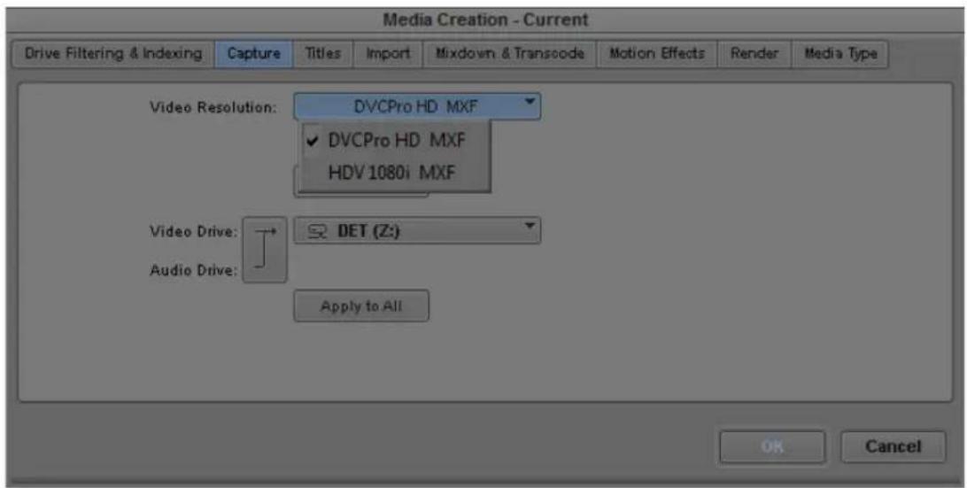
4. Click the Video Resolution menu, and select a video resolution.
The Video Resolution menu contains a list of the available resolutions, which depend on such factors as the model of your Avid editing application, your Avid input/output hardware, and your project format.
For HDV projects, no video resolutions are available for capture, because your Avid editing application automatically selects the correct resolution. For 720p HDV projects,
Avid DNxHD and DVCPRO HD resolutions are listed for other media creation. For 1080 HDV projects, DNxHD-TR resolutions are available for other media creation.
You can restrict the number of video resolutions available to simplify this step. For more information, see “Disabling Video Resolutions” on page 169.
5. Select a video drive and an audio drive. To select the same drive for both video and audio, click the Single/Dual Drives Mode button until only a single drive menu opens.


The drive that appears in boldface type has the most available space.
- (Option) You can select drives and create a drive group. Click the Target Drive menu, and select Change Group. For more information on selecting a drive group, see “Selecting the Target Drives” on page 195.

Because no audio is associated with titles or motion effects, you can select only a video drive in the Titles or the Motion Effects tab of the Media Creation dialog box.
- To apply your video resolution and drive selection to all the Media Creation tabs and the rest of your Avid editing application, click Apply to All.
This sets your selected video and audio drives for all the Media Creation tabs. It also sets them for any place in your Avid editing application where you select drives. Your settings are not saved until you click OK.
- Click OK to save your settings.
For more information about options, see “Media Creation Settings” on page 1424. You can also view this information by clicking the dialog box and pressing the F1 key (Windows) or the Help key (Macintosh).
Disabling Video Resolutions
To simplify the options for media creation, you can use a text file to restrict the resolutions available for capturing, rendering, or importing. If you disable resolutions for media creation, you can still play, export, or perform a digital cut in those resolutions.
To disable resolutions:
- Select Tools > Media Creation.
The Media Creation dialog box opens.
- Click one of the tabs that includes a Resolutions menu, and note the exact spelling of each resolution you want to disable.
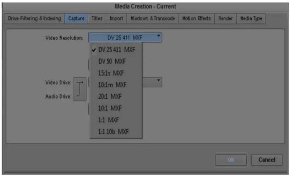
- Open a text file by doing one of the following:
(Windows) Click the Start menu, and then select All Programs > Accessories > Notepad.
▶(Macintosh) Click Go > Applications, and double-click TextEdit.

This file must be a plain text file. On a Windows system, use Notepad. Do not use Wordpad. On a Macintosh system, select TextEdit > Preference > Plain Text. Other files might introduce characters that your Avid editing application cannot recognize.
- Type each resolution you want to disable on a separate line. Do not include OMF or MXF.


DisabledRes.txt examples on Windows (left) and on Macintosh (right)
The text of the resolution must exactly match the text in the Media Creation dialog box. To disable DV 25, for example, type DV 25 411 with DV in capital letters. Do not disable all resolutions supported by your Avid editing application. You need to keep one resolution available.
- (Windows) Name and save the file:
a. Select File > Save As.
b. Type DisabledRes in the File Name text box.
c. Navigate to Program Files > Avid > Avid editing application.
d. Click Save and close Notepad.
- (Macintosh) Name and save the file:
a. Select File > Save As.
b. Type DisabledRes.txt in the File Name text box.
c. Navigate to Applications > Avid editing application.
d. Click Save and close TextEdit.
- If a project is open, close the Project window and open the project again.
Your Avid editing application reads the DisabledRes.txt file when it opens a project and removes the listed resolutions for all projects and all users.
To enable the resolutions you disabled:
▶ Navigate to the location of the DisabledRes.txt file and delete it.
Setting Drive Filtering
Your Avid editing application lets you select any drive on your system to use for media storage. However, high-quality resolutions require striped drives.
Because media files are very large, you can filter drives that are not suitable for media storage out of the list of available drives. Filtering drives in this way provides you with a convenient way to store media only on drives with sufficient space.

If you are working in a network environment, see “Drive Filtering in Networked Workflows” on page 106.

Your Avid editing application does not prevent you from using non-Avid drives, but Avid cannot ensure their reliability.
To set drive filtering in the Media Creation dialog box:
1. Do one of the following:
▶Double-click Media Creation in the Settings list.
▶Select Tools > Media Creation.
The Media Creation dialog box opens.
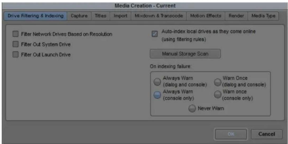
2. (Option) Click the Drive Filtering & Indexing tab.

Options for indexing local drives apply only in an Avid Interplay™ environment. For more information, see the Avid Interplay Software Installation Guide.
3. Select one or more drives to filter out:
▶Select Filter Network Drives Based on Resolution to remove those network drives that cannot support, or handle playback of, the selected resolution.
▶ Select Filter Out System Drive to remove the drive on which the operating system resides.
Select Filter Out Launch Drive to remove the drive on which your Avid editing application resides.
The drive or drives you filter out do not appear in the other Media Creation tabs as possible locations where you can store media. They also do not appear in other drive selection menus in your Avid editing application except for the Import, Export, and Relink dialog boxes.

Your settings are not saved until you click OK.
4. Click OK to save your settings.
For more information about options, see “Media Creation Settings” on page 1424. You can also view this information by clicking the dialog box and pressing the F1 key (Windows) or the Help key (Macintosh).
Selecting Settings for Preroll Method and for Capturing Across Timecode Breaks
If the tape you are capturing contains breaks in the timecode, you can use two settings in the General tab of the Capture Settings dialog box to capture across the timecode breaks.
To select settings for capturing across timecode breaks:
- Double-click Capture in the Settings list of the Project window.
The Capture Settings dialog box opens.
- Click the General tab.
- Click the Preroll Method menu, and select one of the following methods.
Preroll
Method Description
| Best Available | Your Avid editing application first checks the tape for timecode to use for preroll. If there is no timecode, or not enough timecode, your Avid editing application uses the control track for preroll. If there is not enough control track for preroll, your Avid editing application adjusts the specified preroll time to accommodate the amount of valid control track available. If the adjusted preroll time is too short to sync lock at the IN point, your Avid editing application does not capture the shot and displays an error message.After your Avid editing application adjusts the preroll to the individual shot, it returns to using the user-specified preroll time until it needs to adjust the time again.Use this method to capture material as automatically as possible. As the system makes multiple attempts to preroll, this method is slower at times but almost always performs the preroll without interruption. This is the default setting. |
| Standard Timecode | Your Avid editing application uses timecode to determine the preroll point. If there is a not enough consecutive timecode (for example, if there is a break in the timecode), your Avid editing application does not capture the shot and displays an error message.Use this method if you know the timecode is consecutive or if you want to determine if there are timecode breaks. |
Preroll Method Description
| Best Available Control Track | Your Avid editing application uses the control track to determine the preroll point. If there is not enough control track for preroll, your Avid editing application adjusts the specified preroll time to accommodate the amount of valid control track available. If the adjusted preroll time is too short to sync lock at the IN point, your Avid editing application does not capture the shot and displays an error message.After your Avid editing application adjusts the preroll to the individual shot, it returns to using the user-specified preroll time until it needs to adjust the time again.Use this method if you know there are timecode breaks and want to capture material as automatically as possible. Because the system does not use timecode, it might occasionally capture the wrong frames if there is a problem with the control track. |
| Standard Control Track | Your Avid editing application uses the control track to determine the preroll point. If there is a break in the control track, your Avid editing application stops capturing and displays an error message.Use this method if you know the control track is continuous or if you want to determine if there are breaks in the control track. |
- Select or deselect "Capture across timecode breaks."
When you select this option, your Avid editing application begins capturing a new master clip at each timecode break. Select this option when you are performing an unattended batch capture or autocapture. Deselect this option if you plan to capture the entire tape as a single clip by capturing to multiple media files. See “Capturing to Multiple Media Files” on page 174.
- Click OK.
Capturing to Multiple Media Files
You can capture video and audio to multiple media files across multiple drives. MXF is automatically captured to multiple files. OMF ^® is captured to multiple files when you set an option in the Capture Settings dialog box.
Capturing to multiple media files has the following advantages:
- You can create longer clips whose media files would otherwise exceed the file size limitation of 2 GB.
- You can group all drives with the multiple file options. This enables your Avid editing application to capture long clips continuously, for example, satellite feeds.
- Your Avid editing application makes more efficient use of drive space, particularly when capturing long clips.

For media file management purposes, any clip whose media exceeds the 2-GB limit has more than one media file associated with it.
For more information on managing media files, see “Managing Media Files” on page 439.
To capture video or audio to multiple OMF media files:
- Verify that OMF is selected in the Media Type tab of the Media Creation dialog box.
- Double-click Capture in the Settings list of the Project window.
- Click the OMF Media Files tab.
- Select "Capture to multiple files."
For information about other options, see “Capture Settings: OMF Media Files Tab” on page 1364. - Click OK.
- Select Tools > Capture.
The Capture tool opens. - To capture to multiple files across drives, click the Target Drive menu in the Capture tool, and select Change Group.
The Drive Group dialog box opens. - Ctrl+click (Windows) or Command+click (Macintosh) multiple drives to include in the capturing session, or click the All button to select all drives.
If you click Clear, your Avid editing application removes all selections. You must select at least one drive before you can click OK to exit the dialog box. - Click OK.
- Proceed with capturing.
General Settings for Capture
The General Settings dialog box includes the following options that are relevant to capture.
Setting Description
Project Type The top portion of the dialog box displays the project type (NTSC or PAL) and other useful information such as the type of film used as source media.
NTSC Has Setup This option applies to standard NTSC format and is selected by default. If the source footage is in the NTSC-EIAJ format standard (used primarily in Japan), deselect NTSC Has Setup.
For information about other settings in the General Settings dialog box, see “General Settings” on page 1411. For information on opening the General Settings and other settings dialog boxes, see “Viewing and Modifying Settings” on page 1339.
Capture-Related Settings for Film and 24p Projects
The following settings are important when you are capturing video transferred from film or capturing 24p video. You should specify these settings for film or 24p projects immediately after you create a new project and before capturing. For information about other film settings, see “Film and 24P Settings” on page 1406.

Option Description
Video Pulldown Cadence Lets you specify how your Avid editing application handles pulldown frames:
- Video rate, no pulldown: Select this option when capturing 24-fps footage that was transferred MOS (roughly translated as “without sound”) to 30 fps by speeding up the film, and the audio was brought into your Avid system separately at 100 percent of the actual speed.
- Standard 2:3:2:3 pulldown: Select this option when capturing 24-fps footage that was transferred to 30 fps by duplicating frames (pulldown) and the audio is synchronized to the picture.
- Advanced 2:3:3:2 pulldown: Select this option when capturing 24-fps footage that was recorded to 60 fields (NTSC) using Advanced Pulldown and the audio is synchronized to the picture.
If you are capturing sound that was created during an NTSC film-to-tape transfer, set the pulldown switch before you begin capturing. See “Setting the Pulldown Switch” on page 192.
For NTSC projects, you can mix footage transferred with pulldown and footage transferred without pulldown (video rate). You can also mix sound transferred at 0.99 (with pulldown) and 1.00 (without pulldown).
Audio Transfer Rate When you create a 24p PAL film project, you define the audio transfer rate in the New Project dialog box. (You do not need to do this for a 25p PAL project because there is no film speedup during the transfer.) You need to keep the audio transfer rate constant for the project. However, if there is a specific element that you need to capture at a different rate, you can change the rate to one of the following options:
- Film Rate (100%): Select this option when your 24-fps film footage was transferred MOS to 25 fps by speeding up the film, and the audio comes in separately at 100 percent of the actual speed (PAL Method 2).
- Video Rate (100%+): Select this option when your 24-fps film footage was transferred to 25 fps by speeding up the film, and the audio is synchronized to the video picture. This means that the audio speed is increased by 4.1 percent (PAL Method 1).
For PAL 24p projects, you can mix audio that has been transferred at 4.1 percent speedup (video rate, PAL Method 1) with audio that has not been transferred (film rate, PAL Method 2). However, Avid does not recommend this. See “Audio Transfer Options for 24p PAL Projects” on page 1506.

The Info tab in the Project window lets you view the audio transfer rate you selected when you created the project. The actual audio transfer rate might be different from the display if you change the audio transfer rate in the Film and 24p Settings dialog box.
Option Description
| Audio Source TC Rate | Lets you specify the digital audiotape (DAT) timecode format: either 30 fps or 29.97 fps (NTSC only). This timecode format must conform to the timecode format on your original DAT tapes. This setting is active when capturing audio only.This setting does not appear in 23.976 projects. |
| Set Pulldown Phase of Timecode | Lets you set a default pulldown phase for a 24p NTSC project. See “Setting the Pulldown Phase” on page 149. |
Configuring Decks
Deck Configuration settings let you establish deck control parameters for a single deck or for multiple decks. You can create multiple versions, allowing you to select among them for frequent changes in hardware configurations.
Deck Configuration settings and global deck control preferences appear as separate items (Deck Configuration and Deck Preferences) in the Settings list in the Project window.
For information on setting Deck Preferences, see “Deck Preferences Settings” on page 1374. You can also view this information by clicking the dialog box and pressing the F1 key (Windows) or the Help key (Macintosh).
Configuring a Deck or Multiple Decks
To configure a deck or multiple decks:
- Verify that you have manually configured the appropriate hardware connections for the deck or decks.
- Double-click Deck Configuration in the Settings list in the Project window. The Deck Configuration dialog box opens.

- Click the Add Channel button.
The Channel dialog box opens.


Channel refers to the signal path for deck control, whether directly through a serial port, through a V-LAN ^® VLXi system connected to a serial port, or through a FireWire ^® connection. A direct serial port or FireWire connection allows one deck for each channel, while a V-LAN VLXi system allows multiple decks.
- Click the Channel Type menu, and select one of the following items, depending upon your system configuration:
Option Description
FireWire Use if you are controlling a DV camera or deck through a FireWire connection.
Direct Use if you are controlling a deck through an RS-422 connection to the serial port.
Option Description
VLAN VLX Use if you are controlling decks through a V-LAN/VLXi connection
- Click the Port menu, and select one of the following items:
Option Description
OHCI OHCI refers to a FireWire connection on the computer (Host 1394).
COM1 Use if you selected Direct or VLAN VLX for the channel.
- Click OK to close the Channel dialog box.
A dialog box asks if you want to automatically configure the channel now.
- Click Yes if you want to automatically configure the channel.
A new channel appears in the display area of the Deck Configuration dialog box, along with the autoconfigured deck.

Do not autoconfigure a DV camera or deck. Not all DV devices respond to the Auto-configure command. Due to this limitation, Auto-configure selects only a generic device template. When a digital camera is attached to your system, click the Deck Type menu, and select the proper device (described later in this procedure). When a deck is attached, click the Deck Type menu, and select the applicable deck.

Example of a channel (left) and a deck (right) in the display area of the Deck Configuration dialog box

You can reopen the Channel settings to change the options at any time by double-clicking the channel box in the Deck Configuration dialog box.
- If you did not autoconfigure the deck, click the channel box to select it.
- Click the Add Deck button to open the Deck Settings dialog box.

When a deck is already connected to the system, you can click the Auto-configure button to bypass the Deck Settings dialog box and automatically configure a deck with the default settings.

- Select the manufacturer and model number of your deck or other device.
Selecting a model opens a template of settings for the device you selected. You can change these settings based on your device.
For more information, see “Deck Settings” on page 1373. You can also view this information by clicking the dialog box and pressing the F1 key (Windows) or the Help key (Macintosh).
- Click OK to close the Deck Settings dialog box and return to the Deck Configuration dialog box.

You can reopen the Deck Settings dialog box to change the options at any time by double-clicking the deck box in the Deck Configuration dialog box.
- Repeat the channel and deck setup process for each additional channel or deck you want to configure.
- (Option) If you want your Avid editing application to check the deck configuration against the decks physically connected to the system, select “Verify configuration against actual decks.”
Your Avid editing application checks the deck configuration after you click the Apply button in the Deck Configuration dialog box and when you start a work session. A message box warns you if the configuration does not match the deck.
- Type a name in the Configuration name text box to name the deck configuration.
The new deck configuration appears in the Settings list in the Project window.
- Click the Apply button to complete the configurations and close the Deck Configuration dialog box.
- Double-click Deck Preferences in the Settings list in the Project window to review and if necessary adjust global deck control options.
For information about these controls, see “Deck Preferences Settings” on page 1374. You can also view this information by clicking the dialog box and pressing the F1 key (Windows) or the Help key (Macintosh).
Deleting Deck Configuration Elements
You can delete deck configuration elements to remove or replace them.
To delete deck configuration elements:
- Double-click Deck Configuration in the Settings list in the Project window.
The Deck Configuration dialog box opens. - Click a channel box, a deck box, or the entire configuration to select it.
- Click the Delete button.
- Click the Apply button to complete the changes and close the dialog box.
Understanding Timecode
Timecode is an electronic indexing method that denotes hours, minutes, seconds, and frames that have elapsed in video material. For example, a timecode of 01:03:30:10 denotes a frame that is marked at 1 hour, 3 minutes, 30 seconds, and 10 frames.
Most video formats, including PAL and HD formats, use non-drop-frame timecode, where every frame of the video material is counted in sequence.
NTSC video, however, might use either of the following two formats:
- Drop-frame timecode matches the NTSC scan rate of 29.97 frames per second (fps) by dropping two frames of timecode every minute except for the tenth minute. This does not drop any of the video frames themselves. Drop-frame timecode is indicated by semicolons between the digits, for example, 01;00;00;00.
- Non-drop-frame timecode tracks NTSC video at a rate of 30 fps and is indicated by colons between the digits, for example, 01:00:00:00. Non-drop-frame timecode is easier to work with, but does not provide accurate timing for NTSC broadcast.
For example, if you work on a 1-hour show that uses 52 minutes of video, the program ends at 01:52:00:00 (non-drop-frame). If it is broadcast at 29.97 fps, it will last 94 frames too long (approximately 3 seconds).
The following illustration compares the two types of timecode at the 1-minute mark. Remember that no frames are actually dropped when drop-frame timecode is used. Drop-frame timecode simply skips timecode numbers as necessary to match the actual NTSC scan rate.

Comparison of non-drop-frame timecode (top) and drop-frame timecode (bottom)
You set the default timecode format for logging clips in the Deck Preferences dialog box. You set the default starting timecode in the General Settings dialog box. In both cases, you can select either drop or non-drop. For more information, see “Deck Preferences Settings” on page 1374 and “General Settings” on page 1411.
You can also change the starting timecode or, for NTSC projects, the timecode format, of a sequence. See “Changing the Name and Timecode for a Sequence” on page 577.
Connecting a DV Device
You can capture DV 25, DV 50, DVCPRO HD, and HDV media directly from a DV camera or deck (a DV device). For more information, see “Capturing Directly from a DV Device” on page 234. You can also play and output directly to the DV device. To use a DV device, you must connect it to your system correctly.
You can connect a DV device to a 1394 port on your computer (Host 1394)
For HDV media, playback directly to an HDV device is not supported. You need to export a transport stream. For more information, see “Outputting HDV” on page 1529.
Setting Up the Capture Tool
The Capture tool provides controls for cueing, marking, and logging footage, and specifies capturing parameters such as source and target locations. The topics in this section describe how to open and set up the Capture tool.

In Capture mode, the Client monitor displays the playback footage whenever the video track is selected in the Capture tool.
The following illustrations show the Capture tool for an HD project. Some items might not be available or might have minor differences in your Avid editing application model.

Top of Capture tool
1 Trash 8 Record button
2 Capture/Log Mode button 9 Channel Selection buttons
3 Toggle Source/Record button 10 Audio Channel Grouping buttons
4 Video tool 11 Message bar
5 Audio tool 12 Video and Audio Input menus
6 Passthrough Mix tool 13 Subclip status indicator
7 Edit to Timeline buttons (optional) 14 Video Lock icon

Bottom of Capture tool
1 Clip Name text box 6 Deck controls
2 Clip comment text box 7 Deck Selection menu
3 Resolution menu 8 Source Tape Display button
4 Single/Dual Drive Mode button 9 Time remaining on target drive(s)
5 Target Drive menus
When you are working in a 24p NTSC project, the Capture tool includes a pulldown button. For more information, see “Setting the Pulldown Switch” on page 192.
When you are working in an Avid Interplay environment, the Capture tool lets you select either Local Bins or Remote Bins. See “Selecting a Target Bin” on page 194.

When you install your Avid editing application, an Incompatible Power Scheme warning button might appear in the top right corner of the Capture tool. Some Windows power schemes might affect the performance of your Avid editing application, including capturing media. Avid recommends the “Always On” power scheme for Windows XP and the “High Performance” power option for Windows Vista when working with Avid editing applications. For more information on Windows power schemes, see the Windows documentation.
Opening the Capture Tool
To open the Capture tool:
- Ensure the deck or other playback device is properly connected to the system and is turned on.
- Do one of the following:
▶Click a bin to activate it and select Bin > Go To Capture Mode.
▶Select Tools > Capture.
- Set the Capture tool to either Log or Capture mode by clicking the Capture/Log Mode button until the correct mode displays.

Selecting a Deck in the Capture Tool
The Deck Selection menu in the Capture tool contains a list of any decks that are connected to the system, powered up, and initialized when you enter Capture mode.

Device templates from Meridien-based Avid editing applications are not compatible with current Avid editing applications. Do not copy Meridien device templates to current Avid editing systems, and do not copy current Avid editing application device templates to Meridien systems.
The Deck Selection menu also lists the following three commands:
Command Description
Adjust Deck Opens the Deck Settings dialog box. Changes you make apply to the selected deck. For information on Deck settings, see “Deck Settings” on page 1373.
Auto-configure Lets you automatically configure the selected deck with the default deck settings for that deck.
Check Decks Helps to reestablish deck control if the power to your decks was turned off or the decks were disconnected when you first entered Capture mode.
If “No Deck” appears in the Deck Selection menu, you need to configure a deck in the Deck Configuration dialog box. See “Configuring Decks” on page 179.
If a deck name appears in italics in the Deck Selection menu, the deck has lost power or has been disconnected. Click the menu, and select Check Decks to reestablish deck control.

After deck control has been properly initialized, it remains active for all deck controllers throughout the session until you quit your Avid editing application.
You must have V-LAN VLXi hardware to manage more than one deck at a time. For more information on V-LAN equipment, contact your Avid sales representative.
Activating Playback from an Available Deck
To activate playback from an available deck:
▶Click the Deck Selection menu, and select the deck.
Selecting a Source Tape
To select a source tape:
- Do one of the following:
If a tape is already in the deck, click the Source Tape Display button in the Capture tool.
▶ If there is no tape in the deck, insert a tape into the deck.
The Select Tape dialog box opens.

- If you are working in an NTSC project, play the tape for a few seconds so your system can detect the timecode format of the tape (drop-frame or non-drop-frame).
Otherwise, the system maintains the timecode format set in the Deck Preferences dialog box, regardless of the format on the tape, and you might receive a message indicating a wrong tape.

Drop-frame timecode appears in the Timecode indicator with semicolons between hours, minutes, seconds, and frames. Non-drop-frame timecode appears with colons. For more information, see “Understanding Timecode” on page 183.
- Provide the system with a tape name in one of the following ways:
▶ Select the name of the tape from the list in the Select Tape dialog box and click OK.
Expand the list by selecting the “Show other projects” option or by clicking the Scan for tapes button.
Click New if the tape is not in the list. A new tape name line appears in the dialog box. Type the new name, press Enter (Windows) or Return (Macintosh), and click OK.
For information on tape naming conventions, see “Naming Tapes” on page 138. If you are working with MultiRez in an Avid Interplay environment, see “Guidelines for MultiRez Tape Management” on page 1253.
Selecting Source Tracks and Audio Channels
You can select the tracks to capture from the source tape, and you can set the audio channel groupings if you capture stereo audio source media.
When you group audio tracks for multichannel capture or batch capture, your Avid editing application saves the grouping as a capture setting, independent of the hardware channels you select. The resulting clip uses the grouping setting and the used channels. For more information on audio channel groupings, see “Working with Multichannel Audio Tracks” on page 762.
When you batch capture, if the tracks are already logged into the bin then channel selection is made automatically unless you deselect the option “Capture the tracks logged for each clip” in the Batch tab of the Capture Settings dialog box. For more information on Batch Capture settings, see “Batch Capturing Clips” on page 241.
Batch capture uses the audio channel groupings currently specified on the master clip, not the groupings that display in the Capture tool when you batch capture previously-logged clips.
To select only those tracks you want to capture:
▶Click the Channel Selection buttons in the Capture tool.

Channel Selection buttons in the Capture tool
If you do not see source video or hear source audio in Capture mode, click the Channel Selection buttons to ensure they are not the cause.

When you use an Avid-controlled deck, the TC (timecode) track is selected by default, and the system captures the timecode from the source tape. If you deselect the TC button, the system captures with time-of-day timecode. For more information, see "Capturing with Time-of-Day Timecode" on page 233.
To group tracks for multichannel capture:
▶ Click the Audio Channel Grouping buttons in the Capture tool for those tracks you want to capture as stereo audio tracks.
The Audio Channel Grouping button turns green when you group tracks.

Audio Channel Grouping buttons in the Capture tool
When you capture stereo audio, you can view the multichannel audio format in the bin in the Track Formats column.
Setting the Video and Audio Input in the Capture Tool
The Video and Audio menus show you the current input settings for the Video Input tool and the Input tab in the Audio Project Settings dialog box. The menus also provide a convenient way to change the settings if necessary.

The Video Input tool is not available on all models. If your model does not have the Video Input tool, your Avid editing application sets the default input options automatically.
For more information, see “Preparing to Capture Audio” on page 198 and “Preparing to Capture Video” on page 212.

If you change the settings, the settings in the Video Input tool or in the Audio Project Settings dialog box automatically change to the settings you select.
Detecting a Valid or Locked Sync Signal
On systems using Avid input/output hardware, the Capture tool uses an icon to indicate if the sync source you are using is valid and locked. The icon appears in the message bar of the Capture tool.

- Video Lock icon: When you select a video track in the Capture tool, the Video Lock icon is displayed. If the current source has a valid video signal and your Avid input/output hardware can lock to it, the icon is displayed in green. If there is no valid signal, the icon is displayed in black.
- Ref Lock icon: When you select only audio tracks (or if no tracks are selected) in the Capture tool, the Ref Lock icon is displayed. If there is a valid reference signal and your Avid input/output hardware can lock to it, the icon is displayed as a green ring. If there is no valid signal, the icon is displayed in black.


The Ref Lock icon also appears in the Digital Cut tool.
For more information, see Selecting the Sync Source for Output.
Setting the Pulldown Switch
If you are capturing sound created during an NTSC film-to-tape transfer, you need to set the pulldown switch before you begin capturing. If you are capturing picture only, you do not need to set the switch.
If you are working in a 23.976p project, the pulldown switch is not necessary and does not appear.

Ensure your film preferences are set properly. For more information, see “Film Project Pulldown and Transfer Settings” on page 193 and “Capturing Digital Audio in Film Projects” on page 194.
To set the pulldown switch:
▶Click the Pulldown button in the Capture tool.
When the pulldown switch is off, the button is inactive (gray), and a label explains that audio will be captured (sampled) at the same speed at which it was recorded (1.00).
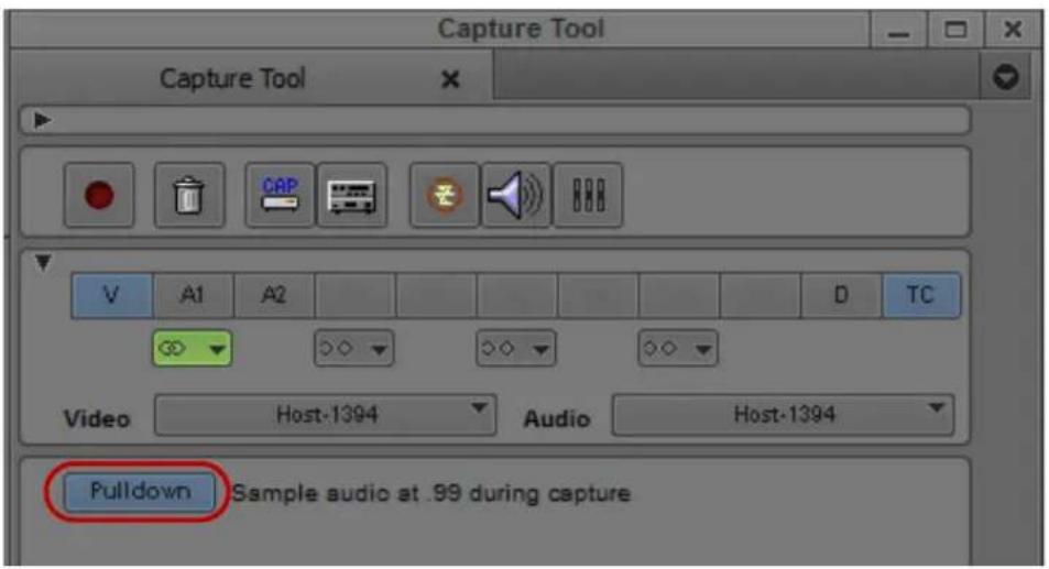
Pulldown button in the Capture tool
When the pulldown switch is on a label explains that you can capture audio sampled at 0.99 percent of its recorded speed (referenced to NTSC video), to match the slowdown rate at which the footage was transferred.
Film Project Pulldown and Transfer Settings
The following table explains how you should set the pulldown switch and transfer settings, depending on your input media.
| Type of Input Media Project | Pulldown Switch Setting | Source Playback Speed | Film to Video Transfer Settings (Set in Film Settings Dialog Box) | |
| Original sound source synced to NTSC during transfer. For capturing picture and sound from NTSC tape, or sound-only from simul-DAT tapes created during telecine transfer. | 24p NTSC On (0.99) 29.97 fps Picture Transfer Rate:With 2:3 pulldown | |||
| NTSC MOS film-to-tape transfer with separate audio. Digital audio (DAT) or analog audio (Nagra) to sync with video in your Avid system. For direct input of separately recorded audio. | 24p NTSC Off (1.00) Audio:30.00 fpsPicture:29.97 fps | Picture Transfer Rate:With 2:3 pulldownAudio Source Tape TCRate: 30.00 | ||
| FTFT transfer or retransferring an effect. This method lets you save time because no audio is involved in the transfer. | 24p NTSC Not applicable | 29.97 fps Picture Transfer Rate:Without pulldown | ||
| PAL film-to-tape transfer with synced sound or simul-DAT tapes. | 24p PAL (Method 1) | Off (1.00) | Audio and picture both 25 fps (100%+) | Picture Transfer Rate: Not applicableAudio Transfer Rate: Video Rate |
| PAL MOS film-to-tape transfer with separate audio. Digital audio (DAT) or analog audio (Nagra) to sync with video in the Avid system. | 24p PAL (Method 2) | Off (1.00) | Audio: 25 fps (100%)Picture: 25 fps | Picture Transfer Rate: Not applicableAudio Transfer Rate: Film Rate |
| PAL film-to-tape transfer with synced sound or simul-DAT tapes. | 25p Off (1.00) | Sound and | picture at 25 fps | Picture Transfer Rate: Not applicable |
Capturing Digital Audio in Film Projects
You must capture audio created during an NTSC file-to-tape transfer at a pulldown sample rate. When capturing from a digital source (such as AES/EBU, ADAT, or Embedded SDI), you must either configure the deck to transfer at the pulldown rate (as is possible with some audio decks) or capture the digital source as analog.
Selecting a Resolution in the Capture Tool
The Res (Resolution) menu contains a list of the available resolutions, depending on your project and the model of your Avid editing application. You can select the resolution in the Capture tool or in the Media Creation dialog box (see “Selecting Video Resolutions and Media Drives” on page 167). If you select a resolution in the Capture tool, the Media Creation settings change to the resolution you selected.
For detailed information on available resolutions in Avid editing applications, see “Resolution Specifications” on page 1470
To select a resolution in the Capture tool:
▶Click the Res (Resolution) menu, and make a selection.
Selecting a Target Bin
You select a target bin as the destination for the master clips that you create when you capture and log at the same time.
In an Avid Interplay environment, the Capture tool includes an option to capture to a local bin or a remote folder.
To select a target bin:
- (Option — systems in an Avid Interplay environment only) Do one of the following:
▶If you are capturing to a local bin, select Local Bins.
If you are capturing to a remote project folder in an Avid Interplay environment, select Interplay Folders.
For more information about capturing to an Interplay project folder, see “Capturing Media to Interplay Folders” on page 1193.

- In the Capture tool, click the Bin menu and make a selection.
Only open bins (and open Interplay folders if you are in an Interplay environment) appear in the Bin menu. For information on opening a bin, see “Opening and Closing Bins” on page 74.
Interplay folders are available only in Avid workgroups configurations. If the Interplay folder you want to use is not open, click the folder name in the Interplay Window.
Selecting the Target Drives
You select one or more target drives as the destination for audio and video media files that you create when you capture.
By default, the Capture tool targets a single media drive volume for capturing the audio and video for each clip. You can also:
- Target separate physical drives for audio and video tracks.
You might want to target separate drives for media management, such as sending audio files to a Pro Tools ^® system for audio sweetening. Capturing audio and video to separate drives is not necessary for performance.
- Target a drive group (a group of media drives).
This is especially useful when you are capturing long clips to multiple media files. For more information, see “Capturing to Multiple Media Files” on page 174.
After you create a drive group, it appears in the Target Drive menu for the project.
If you are capturing high-quality resolutions, you need to select striped drives. For more information, see “Getting Information About Striped Drives” on page 164 and “Storage Options and Drive Striping” in the Help.
You can filter some drives out of the available drive list. For more information, see “Setting Drive Filtering” on page 171.
You can set target drives in the Media Creation dialog box. See “Selecting Video Resolutions and Media Drives” on page 167.

For tips on targeting media drives for effective storage and playback, see “Storage Requirements” on page 1485.
To target a single drive:
- If the Capture tool is not already open, select Tools > Capture.
The Capture tool opens.

- Click the Single/Dual Drive Mode button to display the Single Drive icon.
- Click the Target Drive menu, and select a drive volume.
The name in bold in the menu has the most storage available. The time remaining on the selected drive, displayed to the right of the menu, is calculated based on your resolution selection.
To target separate drives for audio and video:
- If the Capture tool is not already open, select Tools > Capture.
The Capture tool opens.

- Click the Single/Dual Drive Mode button to display the Dual Drive icon.
Two Target Drive menus appear. The top one is targeted for video and the bottom one is targeted for audio.
- Click each Target Drive menu, and select separate drives for audio and video.
The names in bold in the menus have the most storage available. The time remaining on each selected drive, displayed to the right of each menu, is calculated based on your resolution selection.
To create and target a drive group:
- Click the Target Drive menu, and select Change Group. The Drive Group dialog box opens.

-
Ctrl+click (Windows) or Command+click (Macintosh) to select multiple drives to include in the capturing session, or click the All button to select all drives.
-
Click OK.
Your Avid editing application creates the drive group, and it appears in the Target Drive menu.
When you capture, any clip that exceeds the capacity of a drive (whether that drive is empty or already contains media files) continues capturing onto another drive in the group.
Selecting a Custom Preroll
The Custom Preroll option and menu in the Capture tool lets you select how many seconds the tape rolls before the capturing starts. This option overrides the global preroll setting in the Deck Settings dialog box.

Preparing to Capture Audio
Your Avid editing application provides you with a wide range of options for audio input: capturing audio with video from tape, capturing audio from a digital or analog deck, capturing through a microphone, or capturing through an external audio device such as an Mbox device, and in various formats and at various sample rates.
The topics in this section describe preparations you might need to take before capturing audio.
Audio Project Settings for Capture
You can use the Audio Project Settings dialog box to choose various input and output options and check the current configuration of your audio hardware. You need to set the following audio project settings for capture:
Setting For more information, see
| Audio sample rate | “Selecting the Audio Sample Rate and Controlling Audio Sample Rate Conversion” on page 199. |
| Audio file format | “Selecting the Audio File Format” on page 200. |
| Audio input source | “Selecting the Audio Input Source” on page 201. |

Some options depend on the audio configuration of your Avid editing system, so your system might not contain certain features and hardware that are covered in the documentation.
The values you set in the Audio Project Settings dialog box are saved as Project settings. You can also save the Audio Project settings as Site settings so that all projects open with the same audio settings. See “Using Site Settings” on page 1347.
For information on all Audio Project settings, see “Audio Project Settings” on page 1354. You can also view this information by clicking the dialog box and pressing the F1 key (Windows) or the Help key (Macintosh).
Selecting the Audio Sample Rate and Controlling Audio Sample Rate Conversion
Selecting the audio sample rate in the Audio Project settings dialog box sets the audio sample rate for capturing audio and for sequences that you create in the project. You can change the sample rate for individual sequences and audio clips.
When you are using some Avid input/output hardware devices, you can also control how your Avid editing application handles audio sample rate conversion during capture.
Sample rate conversion on input applies to the following digital inputs: SDI embedded, AES/EBU, SPDIF, and ADAT.
To select the audio sample rate:
- In the Project window, click the Settings tab.
The Settings list appears.
- Double-click Audio Project.
The Audio Project Settings dialog box opens.
-
Click the Main tab.
-
Click the Sample Rate menu, and select a sample rate.
-
Close the Audio Project Settings dialog box.
To set a preference for audio sample rate conversion during capture:
-
In the Project window, click the Settings tab.
-
Double-click Audio Project.
The Audio Project Settings dialog box opens.
-
Click the Input tab.
-
Click the Sample Rate Conversion menu, and select on of the following:
Option Description
Never When this option is set, your Avid editing application displays a
warning message if the sample rate of the incoming media does not match the project sample rate. This is the default option.
The Never option is useful when capturing from different sources. The system reminds you that the material that you are capturing is at a different sample rate than the project. Then you can decide whether to convert the audio to match the project sample rate or change the project sample rate to match the incoming audio.
Option Description
When needed When this option is set, your Avid editing application automatically converts incoming audio sample rates to match the project sample rate.
- Close the Audio Project Settings dialog box.
Selecting the Audio File Format
You create audio files when you:
- Record audio tracks in Capture mode.
- Create tone media by using the Audio tool.
- Mix down audio tracks by using the Audio Mixdown tool.
- Import files by using the Import dialog box.
- Apply an AudioSuite plug-in that creates new source audio.
You select the file format that your Avid editing application uses when creating audio files by selecting from the Audio File Format menu in the Audio Project Settings dialog box.
You should be aware of the following:
- You can mix AIFF-C and WAVE audio media files within a project.
- You should elect AIFF-C or WAVE when you need to transfer media files directly to a Pro Tools system for audio sweetening. For more information, see “Transferring Audio Files” on page 1128.
- Media Composer has limited support for Sound Designer II™ audio. See “Transferring and Working with Sound Designer II Audio Files from Macintosh Systems” on page 1129.
- If you switch the audio format in the middle of a project, all new audio media files are written in the new format with the following exceptions:
- When your Avid editing application renders audio effects, it uses the file type of the outgoing (A-side) audio media for a transition. For example, if the A-side of an audio dissolve is in AIFF-C format and the B-side (incoming) is in WAVE format, the rendered file is AIFF-C.
- Media files that your Avid editing application copies or creates during a Consolidate procedure retain their original file types.
To select the audio file format:
- In the Project window, click the Settings tab.
The Settings list appears.
- Double-click Audio Project.
The Audio Project Settings dialog box opens.
- Click the Main tab.
- Click the Audio File Format menu, and select WAVE (OMF), AIFF-C (OMF), or PCM (MXF).
The default file format is AIFF-C (OMF). For more information on audio file formats, see “Audio Projects Settings: Main Tab” on page 1354.
- Close the Audio Project Settings dialog box.
Selecting the Audio Input Source
You can connect one or more audio devices to your Avid hardware or to your computer. Use the Audio Project settings to select the device you want to use as the source for capture. The choices available depend on your system configuration. For more information, see “Audio Project Settings: Input Tab” on page 1356.

If you select IEEE 1394 as your input device, the input source is automatically set to Host-1394. For more information, see “Connecting a DV Device” on page 184.

(Macintosh only) If you use the one of the Mbox family of audio devices to capture audio, the S/PDIF inputs appear in the Capture tool as Tracks 3-4.
To select the audio input source:
- In the Project window, click the Settings tab.
- Double-click Audio Project.
The Audio Project Settings dialog box opens. - Click the Input tab.
- Click the Input Source menu and select the source for the audio you want to capture.
- Close the Audio Project Settings dialog box.
The source you selected is displayed in the Capture tool. You can change the source in the Audio Project Settings dialog box or in the Capture tool.
Configuring the Sound Card (Software-Only Systems)
Depending on the sound card installed on your Avid system, you might need to customize the configuration of audio input and output. Usually this configuration occurs automatically when you install your Avid editing application, but some sound cards require further customization to
ensure full compatibility between your Avid editing application and your audio hardware. In these cases, you can use the Sound Card Configuration dialog box to map audio input sources to specific audio output sources.
If your system has a surround sound audio chip installed, your Avid editing application might not be able to configure the Windows Mixer properly for audio output. By default, your Avid editing application mutes all output sources except the primary audio, which typically is a WAVE source. Some surround sound devices require that other audio output sources, such as Front Speakers, not be muted. To prevent your Avid editing application from muting these outputs, you can override the Sound Card Configuration setting.

Improper configuration of your audio hardware can cause the audio input and output features of your Avid editing application to function incorrectly. Use the Sound Card Configuration dialog box only if you experience problems with your audio output.

Configuring your sound card to ensure compatibility is necessary only if your Avid editing application is not using Avid input/output hardware (software-only). If Sound Card Configuration does not appear in the Settings scroll list, you do not have to configure your sound card.
To customize the sound card configuration:
- In the Project window, click the Settings tab.
The Settings list appears.
- Double-click Sound Card Configuration.
The Sound Card Configuration dialog box opens.
- For each input source in the Record/Input list that you want to map, click the matching Output Source menu from the Playback/Output list and select an output source.

You can map an input source to only one output source at a time. The options available for mapping depend on your audio hardware.
-
(Option) If you do not want an input source mapped to an output source, select
from the corresponding Output Source menu. You might need to do this, for example, if your system lists more input sources than output sources. -
Click OK.
To reconfigure the sound card to the original application settings:
▶Click the Default button.

Clicking the Default button applies the default settings immediately. You cannot cancel the reconfiguration once you reset the default options.
To override the mute feature for surround sound:
-
In the Settings list, double-click Sound Card Configuration.
The Sound Card Configuration dialog box opens. -
Click the Override Mute menu.
The menu contains a list of the output sources available in Windows Master Volume control.
- Click one or more of the output sources to override the Sound Card Configuration settings and to accept the default settings of the Master Volume control.
For example, if the Master Volume control is set to disable sound from the Front Speaker output source, your Avid editing application leaves the source muted. If the Master Volume control is set to enable sound from this source, your Avid editing application leaves the source not muted.
Understanding the Audio Tool
You use the Audio tool primarily for mixing and monitoring audio.
The Audio tool, along with your hardware's audio parameters, lets you do the following in preparation for input:
- Check and manage your audio hardware setup.
- Set audio levels before recording.
- Calibrate, set levels, and generate customized calibration tones for output to the speakers or a record device.
The following table describes the components in the Audio tool.
Component Description
| Reset Peak button Resets the current maximum peak measurements and stops the playback of the internal calibration tone. | |
| In/Out toggle buttons Switch the meter displays for each channel between input levels from a source device and output levels to the speakers and record devices.I indicates Input, and O indicates Output. | |
| Peak Hold Menu button | Lets you select options for customizing the meter displays and for setting and playing back the internal calibration tone. |
| Digital scale to the left of the meters | Displays a fixed range of values from 0 to -90 decibels (dB), according to common digital peak meter standards. |
Component Description
Volume unit (VU) displays a range of values that you can conform to the headroom scale (analog) to the right of the meters parameters of your source audio.
Meters Dynamically track audio levels for each channel as follows:
- Meters show green below the target reference level (default reference level is -20 dB on the digital scale).
- Meters show yellow for the normal headroom range, above the reference level to approximately -3 dB.
- Meters show red for peaks approaching overload, between -3 dB and 0 (zero) dB.
- Thin green lines at the bottom indicate signals below the display range.
Opening the Audio Tool
To open the Audio tool, do one of the following:
▶Select Tools > Audio Tool.
▶Click the Audio Tool button in the Capture tool.
The Audio tool opens and displays meters for two to sixteen channels, depending on the configuration of your system.


Audio tool. Top, left to right: Reset Peak (RP) button, In/Out toggle buttons, Peak Hold (PH) Menu button. Left display column: Digital scale (fixed). Right display column: Volume unit scale (adjustable).
Adjusting Audio Input Levels
You can use the Audio tool and the Audio Project Settings dialog box to check the audio input levels. If the input levels are too high or too low, you need to adjust the output level of your source signal, if possible.

On software-only systems, you can adjust audio input through a slider in the Input tab of the Audio Project settings. For more information, see “Audio Project Settings: Input Tab” on page 1356.
Before you capture, make sure the audio I/O device is properly calibrated. See “Calibrating Audio Hardware for Avid Nitris DX and Avid Mojo DX” on page 208.
To check and adjust input levels using an audio input device:

- Click the In/Out toggle buttons in the Audio tool for the channels that you use for input. The Audio tool displays an I for Input.
- Play back the source audio (from a videotape or DAT, for example). If the recording includes reference tone, cue to the tone and play it back.
- Adjust the output on the playback device so that the device's volume meter shows the appropriate level for the reference signal in the Audio tool (0 VU for videotape playback, for example).
You can adjust the output by using a deck that supports output gain or by sending the signal through a mixing console.
Creating Tone Media
You can create your own tone media as a master clip for editing directly into sequences.
To create tone media:
- Open a bin.
- Select Tools > Audio tool.
- Click the PH (Peak Hold) menu in the Audio tool, and select Create Tone Media. The Create Tone Media dialog box opens.

- Set the appropriate calibration tone parameters for the project. You can also use the default output tone of -20 dB (digital scale) with a 1000-Hz signal.
A value of 0 generates random noise. A value of -777 generates a tone sweep.
-
Select the number of tracks of tone you want to create (up to 8 tracks).
-
Click the menus, and select a target bin for the tone master clip and a target drive for the tone media file.
7. Click OK.
After a few seconds, your Avid editing application creates the media file and a master clip appears in the target bin. The default name reflects the options you selected. You can rename the clip by typing a new name.
Using the Passthrough Mix Tool
The Passthrough Mix tool lets you select the mix and adjust the volume and pan values of the source audio that you monitor. You can adjust the mix, volume, and pan values of multiple monitored channels, controlling either individual channels manually or several channels simultaneously by grouping them together.

The Passthrough Mix tool adjusts monitored audio only and has no effect on the recorded audio signal. You can adjust volume levels within a clip in the Timeline after you record audio by using Audio Gain Automation. For information, see “Audio Mixer Tool Controls” on page 789.
To open the Passthrough Mix tool, do one of the following:
In the Settings list of the Project window, double-click the Passthrough Mix Tool button.
▶In the Capture tool, click the Passthrough Mix Tool button.
▶In the Audio Punch-In tool, click the Passthrough Mix Tool button.
For more information, see “Recording Voice-Over Narration Using Audio Punch-in” on page 853.
The Audio Project Settings dialog box opens.
To choose the number of tracks (4 or 8) to display in the Passthrough Mix tool:
▶Click the Number of Mix Panes button.
When you select 4 tracks, an additional button appears that lets you display the first 4 or last 4 enabled tracks.
With the tool minimized, you can continue to adjust levels, either by selecting a track and typing values by using the numeric keypad, or by typing a value in the Volume Level display.
To adjust audio in the Passthrough Mix tool:
- Double-click Passthrough Mix Tool in the Settings list.
The Passthrough Mix tool opens.
- Switch the Input Mix Mode button to select a type of input:
▶ Select Stereo Mix to mix audio channels to a stereo pair. Use the Stereo Mix Tracks menu to specify which stereo pair to use.
▶ Select Direct Mix to send the input signal to its corresponding output channel.
In Direct Mix mode, the Pan Value display and pop-up sliders at the bottom of the Passthrough Mix tool are replaced by Channel Menu buttons.
- Select the audio channel to be adjusted by doing one of the following:

▶Click the Channel Selection button for the appropriate audio channel.
In Direct Out mode, click the Channel Menu button, and select a channel from the menu.
You can select only channels that exist in the source audio.
- Adjust the volume as needed.

You can adjust the volume of multiple channels by clicking the appropriate Group button. For more information, see the next procedure.
- Adjust the pan values as needed.
For more information, see the final procedure in this topic.
To change an audio level value in the audio panel in the Passthrough Mix tool, do one of the following:
▶Click a number along the vertical edge of the Volume Level slider.
▶Click the Volume Level slider, and type a value.
Values are cumulative until you press Enter (Windows) or Return (Macintosh). For example, if you want to enter the value 12, type it. However, if you type 1 and then want to change the value to 2, press Enter (Windows) or Return (Macintosh) before typing the 2.
▶ Click the Volume Level slider, and drag the slider to a new position.
▶Click the Volume Level display, and type a value.
▶Alt+click the Volume Level slider to reset the value to 0 dB.
To adjust the pan values in the audio panel of the Passthrough Mix tool:
Click the Pan Value display to reveal the pop-up slider, and then drag the slider to a new position.

Pan Value display (left) and pop-up slider (right) in the Passthrough Mix tool.
Calibrating Audio Hardware for Avid Nitris DX and Avid Mojo DX
By default, your Avid editing application is calibrated for analog 0 Volume Unit (VU) to be digital -20 dBFS, which matches the default calibration of the Avid Nitris DX and Avid Mojo DX hardware.
You can do two things to calibrate audio — make the audio adjustment to correspond to your hardware calibration setting by using the default, or refine the calibration to get to within 1/4 dB. This will require using additional test equipment — an external calibrated signal generator, a voltmeter, or an oscilloscope.
The Audio Hardware Calibration window lets you change your audio hardware calibration. The calibration settings are stored in the Avid Nitris DX or Avid Mojo DX, and moved with the hardware if it is moved to another computer. If you delete the project, user, or site settings, or reinstall your Avid editing application, the settings are saved in the hardware.
If you have already calibrated your analog audio outputs, you can use the Avid Play Calibration Tone generator by connecting one channel's output to another channel's input.
To calibrate the audio channels for Avid Nitris DX or Avid Mojo DX using the Audio Hardware Calibration tool:
- Connect the analog outputs to the analog inputs on the back of the Avid Nitris DX or Avid Mojo DX.
- Double-click Audio Project in the Settings list of the Project window.
- Click the Hardware tab.
- Click the HW Calibration menu, and select a new default hardware calibration setting: -14 dBFS, -18 dBFS, or -20 dBFS.
A message box opens warning that changing the Hardware Calibration must be synchronized with physical changes to your Audio I/O peripheral.
- Click OK.
- Click the Open Calibration window.
The Audio Hardware Calibration window opens.

- To change the digital level of the meter's display of 0 VU, click Set Reference Level.
The Set Reference Level dialog box opens.
- Enter the new reference level in dB.
This should be set to match the 0 VU standard in your workflow. Avid recommends a -20 dBfs value.
- Select the interface you want to calibrate: Analog XLR input, Analog RCA input, Analog TRS input, Monitor output, or Analog output.
Options vary depending on your Avid input/output hardware. You can calibrate only one channel at a time.
- Select the appropriate channel.
Channels vary depending on your Avid input/output hardware.
- Use the Up and Down buttons to adjust the calibration in 0.5dB increments.
Depending on what you selected in the HW Calibration menu, enter the corresponding Output or Input.
From HW Calibration menu Use for all Outputs Use for all Inputs
| -14 dBFS -6.00 +6.00 |
| -18 dBFS -2.00 +2.00 |
| -20 dBFS 0.00 0.00 |
- Repeat this procedure for each channel.
To calibrate the audio input channels:
- Connect the tone generator to the analog inputs on the back of the Avid Nitris DX or the Avid Mojo DX.
- Double-click Audio Project in the Settings list of the Project window.
- Click the Hardware tab.
- Click Open Calibration window.
The Audio Hardware Calibration window opens. - Select the interface you want to calibrate: Analog XLR input, Analog RCA input, or Analog TRS input.
Options vary depending on the Avid input/output hardware you have connected. You can calibrate only one channel at a time. - Select the appropriate channel.
Channels vary depending on your Avid input/output hardware. - At the bottom of the Audio Hardware Calibration window, click Audio Tool.
The Audio tool opens. - For whichever channels you want to calibrate, switch the Audio Tool channels to input by clicking each In/Out toggle buttons to change the output (O) to input (I).
The In/Out toggle buttons in the Audio Tool switch from O to I and highlight in green. The meters levels re-display. - Set the tone generator output to the reference level set in the Audio Hardware Calibration window.
The following are suggested professional settings:
- Analog XLR input: +4 dBu
- Analog RCA input: -10 dBV
-
Analog TRS input: +4 dBu
-
Use the Up and Down buttons in the Audio Hardware Calibration window to adjust the calibration in 0.5dB increments.
The meters in the Audio tool should display around 0 VU.
- Click Calibrate from the Audio Hardware Calibration window.
The Audio tool changes to Calibrate mode. The scales display a range of approximately 8 dB, and the meters indicate levels within this range.
- Repeat this procedure for each channel.
To calibrate the audio output channels for Avid Nitris DX and Avid Mojo DX:
- Connect the external meter or an oscilloscope to the analog outputs on the back of the Avid Nitris DX or Avid Mojo DX.

If you use a voltmeter or an oscilloscope to perform the calibration, the target calibration voltage displays in the Voltage ptp and RMS area.
- Double-click Audio Project in the Settings list of the Project window.
- Click the Hardware tab.
- Click Open Calibration window.
The Audio Hardware Calibration window opens.
- If you need to adjust the tone level or tone frequency, click the Set button.
The Set Calibration Tone dialog box opens.

You can also access the Set Calibration Tone dialog box from the menu in the Audio Tool window.
- Enter the new tone levels in dB and the new tone frequency in Hz.
- Use the Up and Down buttons to adjust the calibration in 0.5dB increments.
The following are suggested professional settings:
- Monitor output: +4 dBu
-
Analog output: +4 dBu
-
Click OK.
- Select the interface you want to calibrate: Monitor output or Analog output.
Options vary depending on your Avid input/output hardware. You can calibrate only one channel at a time.
- Select the appropriate channel.
Channels vary depending on your Avid input/output hardware.
- Click Play Calibration Tone.
- Repeat this procedure for each channel.
Using the Console Window to Check Audio Levels
Once you have played back audio through the Audio tool, you can use the Console window to view a list of precise information about the peak levels.
To check peak levels in the Console:
- Select Tools > Audio Tool.
The Audio tool opens. - Click the RP (Reset Peak) button to clear your system's record of the most recent maximum peaks.
- Play a sequence or portion of the sequence.
- After playing back the audio, open the Console window by selecting Tools > Console.
- In the Console command line, type:
RP
DumpMaxPeaks

- Press Enter (Windows) or Return (Macintosh).
A list of peak values appears in the Console window.
Preparing to Capture Video
The Video Input tool lets you select the format of the video input signal and calibrate composite video, component video, and S-Video.
If you are capturing SDI, HD-SDI, or DV, for example, from a D1, D5, digital Betacam, DV, or HD deck, you cannot adjust levels by using the video input controls in your Avid editing application. If you plan to make adjustments at the source deck, information in this section regarding the internal Waveform and Vectorscope monitors might be useful.

When used with Avid Nitris input/output hardware, Avid Symphony requires that the deck and the Avid Nitris hardware are genlocked to the same timing source when capturing. For more information, see “Selecting the Sync Source for Capture” on page 164.
Opening the Video Input Tool
To open the Video Input tool, do one of the following:
▶Select Tools > Video Input Tool.
▶Click the Video Input Tool button in the Capture tool.
The Video Input Tool opens.


1 Waveform Monitor button 4 Vectorscope monitor 7 Settings menu
2 Vectorscope Monitor button 5 Input menu 8 100% bars button
3 Waveform monitor 6 Preset buttons
For information about settings in the Video Input tool, see “Video Input Tool Settings” on page 1442.
Using the Factory Preset Buttons in the Video Input Tool
The preset buttons in the Video Input tool show the status of each calibration setting as follows:
- When you first open the Video Input tool in a new project, all preset buttons are lit (green), with the factory presets loaded for each slider.
- When you click the slider of a lit preset button, the arrow changes to black and the slider moves to the position of the pointer.
- When a preset button has a black arrow and you click it, the arrow becomes lit (appears green), and the slider moves to the factory preset level for that parameter.
- When you click a lit preset button, the arrow changes to black, and the slider returns to the last manual setting.
As you adjust levels in the tool, you can switch the preset buttons between the levels you set manually and the factory preset levels.
Calibrating Video Input
You should calibrate video input levels to ensure the continuity of picture quality between tapes. Before you calibrate the video input, check the following:
- Make sure your monitor is properly calibrated for displaying footage accurately. For more information, see your monitor's hardware documentation.
- If your system's output settings have not already been calibrated according to house standards, use the procedures described in “Calibrating for Video Output” on page 1043. If you are in a facility where this is not necessary, leave the output settings at their preset values.
- If you are using footage in the NTSC-EIAJ format (used primarily in Japan), deselect the NTSC Has Setup option in the General Settings dialog box. This enables the appropriate display for the setup portion of the signal in the Waveform monitor and also adjusts the gain range.

When you recapture media from a project created on a different Avid system, only reuse settings that originate on systems that use the same video I/O board. For projects from other Avid systems, check the Video settings for each tape.
To calibrate the video input:
-
Ensure that you have properly connected the video playback device to the system. For more information, see the setup guide for your Avid system.
-
Select Tools > Video Input Tool.
The Video Input tool opens.
- Click the Input menu, and select the appropriate video input channel.
Your options for video input depend on the model of your Avid editing application and the project you select.
The Video Input tool displays the appropriate parameters for the selected video format. For a description of each parameter, click the Video Input tool and press the F1 key (Windows) or Help key (Macintosh).

Sync for video input comes from the source selected in the Video Input tool.
When you capture audio with video, the audio is always synced to the video source. For information regarding sync during audio-only input, see “Establishing Sync for Audio-Only Input” on page 165.
- Cue the tape to the section containing bars and tone (usually the beginning) and play the tape.

Always play the tape when calibrating. Signal display is unstable when the tape is paused.
The Client monitor displays one of the following types of bars (or a variation of them).
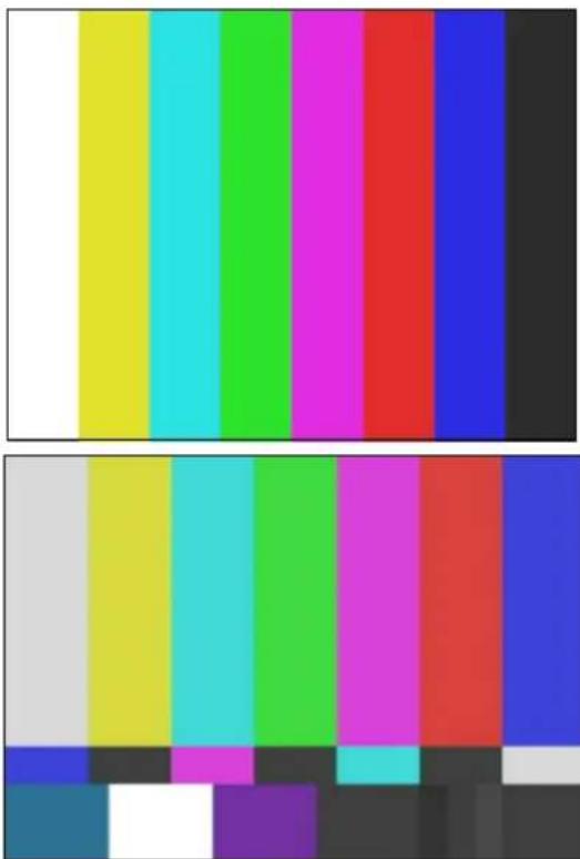
natural_image
Color swatch with vertical bars in yellow, cyan, green, magenta, red, blue, black, and white (no text or symbols)Top: full-field color bars (the leftmost bar is 100% white). Bottom: SMPTE standard split bars (the leftmost bar in the top row of bars is 75% white, the second bar in the center row of bars is 7.5 black level, and the second bar in the bottom row of bars is 100% white).
- If you are capturing from a consumer-grade video deck (such as a home VCR) or a deck that has no built-in time-base corrector, and you are having trouble with the incoming video quality, click the SignalLock button and select Consumer in the Video Input tool.
For more information, see “Limitations When Using Consumer Decks or Decks Without Time-Base Correctors” on page 218.
- Click the 100% Bars button if the source tape contains 100% bars for calibration.

In 100% bars, the luminance waveform plot displays fairly even steps from the first bar (white) to the last bar (black). In 75% bars, the white bar is at 100%, which causes a larger step from the first bar (white) to the first color bar.

- Open the Waveform monitor by clicking the Waveform Monitor button.

line
| Field | Value | | ------- | ----- | | IRE | 100 | | Field 1 | 60 | | Field 2 | 100 |
line
| Field | Value | | ------- | ----- | | Field 1 | 235 | | Field 2 | 16 |NTSC (top) and PAL waveform values in the Video Input tool. NTSC values are measured in IRE, with the white level at 100 IRE (digital 235), the black level at 7.5 IRE (digital 16), and the 75% white level at 77 IRE (digital 180, the horizontal dotted line in the display). For NTSC-EIAJ, the black level falls at 0 IRE. PAL values are measured in volts, with the white level at 1 V (digital 235) and the black level at 0.3 V (digital 16). The Line slider controls appear below the waveform display.
- Adjust the Line slider located below the Waveform monitor to display the appropriate line of the test pattern, then adjust the luminance values as described in "Luminance Settings for Video Input" on page 218.
- Open the Vectorscope monitor by clicking the Vectorscope Monitor button.
- Adjust the Line slider to display the signal for color bars at around line 150 (this applies to all formats and all types of bars).

To switch between a display of perfectly calibrated bars and your input signal while making adjustments, press and release the Shift key.
- Adjust the Sat and Hue sliders (composite or S-Video) or the RY Gain and BY Gain sliders (component) until the angle and amplitude of the six color vectors fall within the target boxes on the Vectorscope monitor.
There is no hue adjustment for PAL video.

You can also monitor hue with a vectorscope in the Color Correction tool. See “Working with the Waveform Monitors and Vectorscope Monitor” in the Help.

If you incorrectly select or deselect the 100% Bars button, the factory presets for Saturation or RY and BY Gain are incorrect. Adjusting these controls in this condition results in oversaturated or undersaturated video.
Luminance Settings for Video Input
The following table describes recommended luminance settings for video input.
| Parameter SMPTE Bars | Full-Field Bars at 75% or 100% Signal Level | |
| Black level (setup) | Adjust Line slider to approximately 190 | Adjust Line slider to approximately 150 |
| Adjust Black or Brightness slider to place black level at: | Adjust Black or Brightness slider to place black level at: | |
| • 7.5 IRE (for NTSC) | • 7.5 IRE (for NTSC) | |
| • 0.0 IRE (for NTSC-EIAJ) | • 0.0 IRE (for NTSC-EIAJ) | |
| • Not applicable for PAL | • 0.3 V (for PAL) | |
| White level (gain) | Adjust Line slider to approximately 220 | Adjust Line slider to approximately 150 |
| Adjust Gain/Y Gain slider to place white level at: | Adjust Gain/Y Gain slider to place white level at: | |
| • 100 IRE (for NTSC and NTSC-EIAJ) | • 100 IRE (for NTSC and NTSC-EIAJ) | |
| • Not applicable for PAL | • 1.0 V (for PAL) | |
Limitations When Using Consumer Decks or Decks Without Time-Base Correctors
This topic describes difficulties you might encounter when working with consumer video decks and tapes or decks that do not provide time-base correction or stabilized timing on their outputs.
Capturing from Unstable Time-Base Sources
Your Avid system is optimized for use with modern, broadcast-quality VTRs that contain time-base correctors (TBCs). If the input is stable, your system captures the video by using a high-quality, very-low-jitter clock reference.
However, some sources do not include an internal TBC. In some cases, due either to the deck performance or the deck performance in conjunction with a particular videotape, your system does not lock to non-TBC sources. As a result, the image might be unstable or might have reduced or missing color, or syncing might not be possible at all.
If you select SignalLock > Consumer in the Video Input tool, a wider bandwidth (more closely tracking time-base) improves the range of syncing capability. In this mode, the video input levels are set by automatic gain control. Not all of the Video Input tool's adjustment sliders operate, and the video might be slightly softened, but the syncing in most cases is more reliable and more stable. The overall image quality is not as high as with normal operation.

The Video Input tool is not available on all models. If your model does not have the Video Input tool, your Avid editing application sets the default input options automatically.
If you continue to experience difficulty with a source that does not include an internal TBC, Avid recommends that your process the video signal through an external TBC for maximum image quality. For more information on time-base correctors, contact your Avid Reseller.
Green Line in VHS Video
Some VHS tape decks do not output the full 240 lines of video normally included in the VHS format. As a result, after you capture from a device such as a VCR, a green line might appear at the bottom of the monitors in your Avid editing application.
This line is at the bottom of the visible area of the picture, and is not seen in a standard consumer monitor in most cases. If you use the video in a circumstance in which the line is visible, you can remove it by cropping the bottom edge of the picture.
Saving Video Input Settings
You can save the settings for an individual tape each time you calibrate bars. Saved settings are restored each time you select the same tape for recapturing clips. The settings that are saved and restored are the Level adjustments made with the sliders and the selection status of the SignalLock or 100% Bars options.

Video Input settings do not restore the source format (Composite, Component, S-Video, DV, or SDI). The source format you select in the Video Input tool remains the default for that project until you select another format from within the project. This lets you establish a new format on a project basis when moving between systems, or from the offline to the online phase.
The Video Input tool is not available on all models. If your model does not have the Video Input tool, your Avid editing application sets the default input options automatically.

If you do not use a name that matches the tape name, your system does not recall the setting automatically the next time you load the tape.
Whenever you batch capture or select a tape name during capturing, your system recalls the saved settings as follows:
- Your system looks for a Tape setting with the same name as the tape. If the setting exists, your system recalls it.
- If no matching Tape setting exists, your system looks for a setting labeled “Default” and loads that setting.
- If no matching Tape setting or “Default” setting exists, the Video Input tool is left in its prior state (with the most recent settings applied during the session).
Tape settings and the Default setting are Project settings, and are available to the current project only.
To save the calibration settings for a tape:
- After calibrating the video input, click the Settings menu in the Video Input tool, and select Save As.
For more information, see “Calibrating Video Input” on page 214.
The View Name dialog box opens. - Accept the default name (matching the tape name), or type a new name for the settings.
- Click OK.
To create a customized default Video Input Tool setting:
- Select Tools > Video Input Tool.
The Video Input tool opens.
- Adjust the Calibration settings.
For more information, see “Calibrating Video Input” on page 214.
- Click the Settings menu in the Video Input tool, and select Save As.
The View Name dialog box opens.
- Type Default, and click OK.
You must use this spelling and initial capitalization.
Adjusting Video Levels for Tapes Without Color Bars
Color bars are the best way to set the video levels consistently. However, if you have a tape or series of tapes with no color bars, you might need to adjust levels by using the internal Waveform and Vectorscope monitors.

Calibrate your Client monitor before making these adjustments.
The following table describes the criteria for adjusting video levels by eye, without color bars.
| Color | Adjustment | Criteria |
| Blacks Should not seem flat and lacking detail. Find a series of frames in the footage that include black areas. Shadows work better than black objects. Blacks should fall around 7.5 IRE for NTSC, 0 IRE for NTSC-EIAJ, or 0.3 V for PAL in the Waveform monitor. | ||
| Whites Should not be washed out or lacking detail. Find a series of frames in the footage that include white areas. Bright, well-lit regions work better than white objects. Whites should peak at around 100 IRE for NTSC-EIAJ or 1.0 V for PAL in the Waveform monitor. | ||
| Skin colors | Should be realistic. Find a series of frames in the footage that include skin colors. Skin colors should fall generally between the target boxes for the red and yellow vectors in the Vectorscope monitor. | |
| Pure yellows Should be a rich gold and not reddish or greenish in tone. Find a pure yellow, and adjust both hue and saturation as necessary. | ||
| Chroma Should not exceed 110 or fall below -120 in the Vectorscope monitor. | ||
Capture Preparations Check List
☐ Check your hardware configurations, particularly connections between your deck and the Avid system. See “Preparing the Hardware for Capture” on page 163.
☐ If you are working on a complex project with multiple streams of video and high-resolution images, make sure your drives are striped properly. See “Getting Information About Striped Drives” on page 164.
☐ Select options in the Media Creation Settings, Capture Settings, General Settings, and (if appropriate) Film and 24P Settings dialog boxes. See “Selecting Settings for Capture” on page 167.
☐ Configure your deck or decks using Deck Configuration and Deck Preferences settings. See “Configuring Decks” on page 179.
☐ Insert a tape into the deck, and set up the Capture tool for source tape, source deck, pulldown switch (24p projects), and other requirements. See “Setting Up the Capture Tool” on page 185.
☐ Select audio settings, and set up the Audio tool. See “Preparing to Capture Audio” on page 198.
☐ Use the Video Input tool to select the input source; set the video input levels for setup, gain, saturation, and hue; save your Video settings for future use. See “Preparing to Capture Video” on page 212.
7 Capturing Media
This chapter provides information on capturing media from video or audio input. When you capture, you convert source material into master clips that contain reference information and media files that contain the digital audio and video.
• Capturing and Logging at the Same Time
• Capturing Directly from a DV Device
- Frame Chase Capture
- Batch Capturing from Logged Clips
• Recapturing and Decomposing
• Using Capture Function Keys
- Handling Errors During the Capture Process
- Creating Subclips While Capturing
- Adding Markers On-the-Fly While Capturing
- Naming a New Tape from the Keyboard While Capturing
- Controlling Decks from the Keyboard
- Ejecting Tapes with a Button or Key
• Delaying Audio During Capture
• Live Capturing with External Timecode
• Capturing to the Timeline
• Capturing Video Without Pulldown into a 24p NTSC Project
- Remote Play, Capture, and Punch-In
• Relinking Clips by Key Number
- Modifying the Pulldown Phase After Capturing
• DV and HDV Scene Extraction
• Using the Panasonic VariCam
For information about setting up the capture tools and adjusting capture settings, see “Preparing for Capture” on page 159.
Capturing and Logging at the Same Time
When you capture without entering log information in a bin ahead of time, your Avid editing application creates clips and associated media files while you capture. You manually cue source footage with an Avid-controlled deck, using the deck controls in the Capture tool.
If you entered log information in a bin, see “Batch Capturing from Logged Clips” on page 239.
There are several ways to capture and log at the same time:
- Capturing from a mark IN to a mark OUT: This method lets you specify the exact timecode location to begin and end capturing. You can specify both marks, or you can set only one mark and let your Avid editing application enter the other mark on-the-fly (see “Capturing by Setting Both Marks” on page 227 and “Capturing by Setting Only One Mark” on page 228).
Use this method in the following circumstances:
- If logs exist in written or printed form but not in the proper format for quick import into your system.
- If the IN and OUT points are rough and need to be double-checked for accuracy.
- If you are familiar enough with the source material to estimate the timecode for the mark IN, the mark OUT, or both, quickly and accurately.
- Capturing on-the-fly: This method is easier than setting marks, but less precise. It involves using the deck controls in the lower left corner of the Capture tool to cue, play, and stop the source footage manually while capturing. See “Capturing On-the-Fly” on page 228.
- Autocapturing: This method requires the least amount of supervision and effort, but usually calls for more capture time and drive storage space. Each source tape plays from a cue point near the beginning and your system captures the entire tape, automatically naming and entering each cut into the bin. See “Autocapturing” on page 231.

Capturing on-the-fly and autocapturing can cause incorrect pulldown and stuttering playback. Do not use these methods for capturing 24-fps film that has been transferred to NTSC video unless you have set the correct pulldown phase. See “Setting the Pulldown Phase” on page 149.
Two additional techniques you can use when capturing and logging at the same time are described in “Capturing from a Non-Avid-Controlled Deck” on page 232 and “Capturing with Time-of-Day Timecode” on page 233.
You can name clips and add comments before or during the capture of a clip. For more information, see “Naming Clips and Adding Comments in the Capture Tool” on page 225.
You can log and capture at the same time with either a PAL or NTSC film-to-tape transfer as the source. However, when capturing an NTSC transfer, you must observe the following basic rules:
- Specify the pulldown frame before capturing. See “Entering Pulldown Information” on page 151.
- The mark IN must be an A frame, and you cannot capture with a mark OUT only, unless you have set the correct pulldown phase. See “Setting the Pulldown Phase” on page 149.
Naming Clips and Adding Comments in the Capture Tool
You can type clip names and comments before or during the on-the-fly capture of a clip. This information is saved in the clip Name and Comments columns in the bin. You can add comments about such things as color correction or directions for editing.
If you do not type a clip name before or during capturing, your Avid editing application provides a default clip name. You can edit a clip name and add a comment in the bin.

To carry your comments over to the sequence so that they appear in the Timeline, in cut lists, or in EDLs, you must add the comments again when creating the sequence by using the Add Comments command in the Clip Name menu. For more information, see “Adding Comments to Sequence Clips” on page 605.
To name a clip and add a comment before capturing:
- Click the arrow in the Capture tool to display the Name and Cmnt text boxes.

Name and Cmnt (comment) text boxes in the Capture tool
- Type a name for the clip.
- (Option) Press the Tab key and type a comment.
You can edit the text before capturing.
To add clip names and comments during capture:
- Click the arrow in the Capture tool to display the Name and Cmnt text boxes.
- Start typing the clip name at any time during the capture of a clip.
- After typing the clip name, press the Tab key and type a comment.
You cannot edit the text until after the capture is complete, but you can backspace to retype the comments.

If the Name text box is not visible on the Capture tool, you can type a clip name but you cannot view your typing. To display the Name text box, you must click the arrow before you begin capturing.
Capturing by Setting Both Marks
To capture by specifying a mark IN and a mark OUT:
- Select the proper Capture settings and set up the capture tools, as described in “Preparing for Capture” on page 159.
- (Option) Click the arrow in the Capture tool to display the Name and Cmnt text boxes if you plan to enter clip names or comments.
You can enter this information before you capture a clip or while you are capturing a clip. See “Naming Clips and Adding Comments in the Capture Tool” on page 225.
- Set either a mark IN or a mark OUT for the clip you want to capture, using one of the following methods:


▶ Use the deck controls in the Capture tool. Cue your source tape to where you want to start or end the clip, and click the Mark IN or Mark OUT button.
If the material starts at a known IN point or ends at a known OUT point, you can type the timecode in the display area next to the mark. Press Enter (Windows) or Return (Macintosh) to enter the mark.
To double-check the accuracy of the IN or OUT point, click the Go to IN button. The system cues the tape and pauses the deck at the mark. You can play the tape and reset the mark, if necessary.
- Finish logging the clip, using either of the following methods:
▶Set the corresponding IN or OUT point.
Type a timecode for the clip's duration in the text box next to the Duration mark (below the mark OUT) in the format HH:MM:SS:FF.
Your Avid editing application automatically calculates the appropriate timecode for the corresponding mark IN, mark OUT, or duration.
- Click the Record button in the Capture tool, or press the F4 key.

The Capture tool automatically rewinds the tape to the preroll point before the IN point of the clip, and the tape begins to play. The Record button becomes bright red, and the message bar displays the message that your Avid editing application is capturing.
When the tape reaches the clip's OUT point, capturing stops and your Avid editing application creates a new clip in the bin. It also enters basic log information for each clip, consisting of the mark IN, the mark OUT, the duration, and any other information typed in during the capture procedure.

You can map the Record button from the Play tab in the Command palette to a key on the keyboard. This lets you start capturing by pressing a key. The Record button works for either the Capture tool or the Audio Punch-In tool, depending on which tool is active. For more information on mapping buttons, see “Understanding Button Mapping” on page 110.
- If you did not type a clip name while capturing, type it now while the clip name is highlighted in the bin.
If you return to the Capture tool and begin another clip, the default clip name remains in the bin until you change it.
Capturing by Setting Only One Mark
To set only one mark and enter the other mark on-the-fly:

Mark an IN point and click the Record button to begin capturing. Then, click the Record button again to stop capturing on-the-fly and mark an OUT point.
This method is useful if you do not need a precise OUT point. You save time because you do not have to shuttle to locate the OUT point before capturing.

You can map the Record button from the Play tab in the Command palette to a key on the keyboard. This lets you start capturing by pressing a key. The Record button works for either the Capture tool or the Audio Punch-In tool, depending on which tool is active. For more information on mapping buttons, see “Understanding Button Mapping” on page 110.
Mark an OUT point only, then move to a position on the tape that is a few seconds before where you want to start capturing. Play the tape and then immediately click the Record button to begin capturing on-the-fly.
When the tape reaches the clip's OUT point, capturing stops.
This method is useful if you do not need a precise IN point, but do need to stop at a precise OUT point, for example, just before a timecode break.
Capturing On-the-Fly
Use the capturing on-the-fly method in any of the following circumstances:
- If you need to begin editing immediately and no adequate logs exist for importing into the system or setting marks.
- If your source tape does not have timecode.
- If you are capturing from a digital source such as a CD or DAT player.
• If you are capturing from a live source, such as a satellite feed, or an in-house router. - If you are capturing from a source deck that cannot be controlled by the Capture tool or a V-LAN VLXi unit.

There is a slight delay of several frames after you manually select a spot to either start or to stop capturing. Therefore, use this method when you do not need precise beginning and end points in your clip.

Capturing on-the-fly can cause incorrect pulldown and stuttering playback. Do not use this method for capturing 24-fps film that has been transferred to NTSC video unless you have set the correct pulldown phase. See “Setting the Pulldown Phase” on page 149.
In some circumstances, the captured material might exceed the 2-GB media file size limit. In such a case, set up the Capture tool to capture to multiple media files. For more information, see “Capturing to Multiple Media Files” on page 174.
To capture on-the-fly:
- Select the proper Capture settings and set up the capture tools, as described in "Preparing for Capture" on page 159.
- (Option) Click the arrow in the Capture tool to display the Name and Cmnt text boxes if you plan to enter clip names or comments.
You can enter this information before you capture a clip or while you are capturing a clip. See “Naming Clips and Adding Comments in the Capture Tool” on page 225.
- Use the deck controls in the bottom left corner of the Capture tool to locate the position on the tape where you want to start capturing.
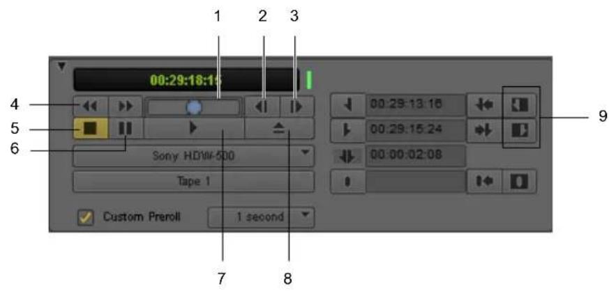
Deck controls in the Capture tool
1 Shuttle button 6 Pause button
2 Single-Frame Backward button 7 Play button
3 Single-Frame Forward button 8 Eject button
4 Fast Forward/Rewind buttons 9 Clear Marks buttons
5 Stop button

- To begin capturing, play the deck. When it gets up to speed, click the Record button or press the F4 key.

Make sure you clear any previous marks so the deck does not begin cueing to the previous location.
Capturing begins within a few frames, and the timecode for the clip's IN point appears. The Capture indicator, to the right of the Record button, flashes on and off. The message bar displays a message that your Avid editing application is capturing.

You can map the Record button from the Play tab in the Command palette to a key on the keyboard. This lets you start capturing by pressing a key. The Record button works for either the Capture tool or the Audio Punch-In tool, depending on which tool is active. For more information on mapping buttons, see “Understanding Button Mapping” on page 110.

If your Avid editing system is an asset manager client in an MXF/AAF workgroup, you cannot create markers while capturing media using the Capture tool. However, you can use the Frame Chase feature when capturing media from a supported external device using Avid Interplay Transfer. For more information about using Frame Chase, see your Avid Interplay documentation.
- Click the Pause button at any time to pause play.
You can also abort the capture procedure by clicking the Trash button. The clip is discarded.
- To stop capturing and enter the OUT point of the clip, click the Record button, or press the Escape key on the keyboard.
Your Avid editing application creates a new clip in the bin. It also enters basic log information for each clip, consisting of the mark IN, the mark OUT, the duration, and any other information typed in during the capture procedure.
- If you did not type a clip name while capturing, type it now while the clip name is highlighted in the bin.
If you return to the Capture tool and begin another clip, the default clip name remains in the bin until you change it.
Preparing to Autocapture
You can autocapture entire tapes to bypass both the logging and cueing processes necessary for other types of capture, as described in “Autocapturing” on page 231.
Before you begin autocapturing entire tapes, you should do the following:
- Select the following settings in the Capture Settings dialog box.
- Capture to multiple files (Media Files tab)
- Maximum default capture time (Media Files tab).
Set this to the length of your tape. Do not underestimate, because the system captures for only the specified number of minutes.
- Preroll Method (General tab)
Set this to Best Available or Best Available Control Track
- Capture across timecode breaks (General tab)
- Log errors to the console and continue capturing (Batch tab)
For more information, see “Viewing and Modifying Settings” on page 1339 and “Capture Settings” on page 1361. You can also view this information by clicking the dialog box and pressing the F1 key (Windows) or the Help key (Macintosh).
- Turn off the FAST CUE option in the Deck Settings dialog box, and set the preroll to approximately 4 seconds. For more information, see “Deck Settings” on page 1373.
- Prepare accurate notes on the number and content of takes on each tape to identify the content of each clip when necessary.
Autocapturing
Autocapturing an entire tape can save you time by allowing you to bypass both the logging process and the time it takes to cue each shot. However, this process requires the most storage space, and it takes time to capture an entire tape.
When you autocapture, you mount and cue your tape to a starting point and start the capturing process through the Capture tool. If you follow the tips and techniques described in this section, you can allow the system to complete the capturing process unattended.
Before autocapturing, you should make sure that you have taken the preparation steps described in “Preparing to Autocapture” on page 230.

Your Avid editing application can capture across timecode breaks, but it cannot capture across control-track breaks in the recording (that is, if the recorded footage breaks up into noise between shots). If such breaks in recording exist on your tape, consider using the methods described in “Capturing On-the-Fly” on page 228.

Capturing on-the-fly can cause incorrect pulldown and stuttering playback. Do not use this method for capturing 24-fps film that has been transferred to NTSC video unless you have set the correct pulldown phase. See “Setting the Pulldown Phase” on page 149.
To autocapture:
- Create one bin for each tape.
This keeps bins to a manageable size and automatically names all clips from each tape after the name of their respective bins. - Name each bin after the source tape number.
By default, all clips are named after the tape and are numbered incrementally beginning with .01. - Open the bin for the first tape and select Bin > Go To Capture Mode.
- Select the proper Capture settings and set up the capture tools, as described in “Preparing for Capture” on page 159.
- Load the source tape and cue past any false starts.
- Play the tape, and wait 4 seconds before clicking the Record button.
At the end of the tape, capturing stops and your Avid editing application creates a new clip in the bin.


You can map the Record button from the Play tab in the Command palette to a key on the keyboard. This lets you start capturing by pressing a key. The Record button works for either the Capture tool or the Audio Punch-In tool, depending on which tool is active. For more information on mapping buttons, see “Understanding Button Mapping” on page 110.
Capturing from a Non-Avid-Controlled Deck
If you have a deck that cannot be controlled directly by the system, you can capture with manual deck control.
To capture with manual deck control:
- Select the proper Capture settings and set up the capture tools as described in “Preparing for Capture” on page 159.
- Click the Toggle Source button in the Capture tool until the Deck Offline icon appears to disable the deck controls and leave only the Tape Name display.


- Click the Timecode Source menu to select the deck.
- Click the Tape Name display to open the Select Tape dialog box and identify the source tape.
You can select the option Show other projects to display the tape names and associated project names for all bins that were opened in the current session.

Because the media file database does not open when you start your Avid editing application, tape names of all online media files do not appear automatically.
If the tape name you are searching for does not appear in the Select Tape dialog box, click the Scan for tapes button to list tape and project names.
- Provide your Avid editing application with a tape name in one of the following ways:
▶ Select the name of the tape from the list in the Select Tape dialog box and click OK.
Click the New button if the tape is not in the list. A New Tape name line appears in the dialog box. Type the new name and click OK.
The tape name appears in the Capture tool.

- Play the tape manually and click the Record button to stop and start the capturing of each clip.

You can map the Record button from the Play tab in the Command palette to a key on the keyboard. This lets you start capturing by pressing a key. The Record button works for either the Capture tool or the Audio Punch-In tool, depending on which tool is active. For more information on mapping buttons, see “Understanding Button Mapping” on page 110.
For information about capturing with external timecode, see “Live Capturing with External Timecode” on page 264.
Capturing with Time-of-Day Timecode
When you capture with an Avid-controlled deck, you can capture your footage with time-of-day timecode rather than source timecode.
To capture with time-of-day timecode:
- Select the proper Capture settings and set up the capture tools, as described in “Preparing for Capture” on page 159.
- When selecting tracks, deselect the TC button.
- Capture by using any of the techniques described in “Capturing and Logging at the Same Time” on page 224.
Capturing Directly from a DV Device
You can capture DV 25, DV 50, DVCPRO HD, and HDV media directly from a DV camera or deck (a DV device). You can also play and output directly to the DV device. To use a DV device, you must connect it your system correctly, as described in “Connecting a DV Device” on page 184.
Capturing DV 25 Media
If you are using an Avid Nitris DX or Mojo DX, or if you are not using an Avid input/output hardware device (software-only), you use a 1394 port on your computer (Host 1394). You specify that you are capturing via the 1394 port by selecting Host 1394 from the Video menu in the Capture tool.
Capturing DV 50, DVCPRO HD, or HDV Media
How you capture DV 50, DVCPRO HD, or HDV media depends on whether you are using Avid input/output hardware and on what type of Avid input/output hardware is connected to your system:
If you are using Avid input/output hardware, or if you are not using an Avid input/output hardware device (software-only), you use a 1394 port on your computer (Host 1394).

For information on playing back DV 50 and DVCPRO HD media, see “Playing Back to a DV Device” on page 514.
Selecting a DV Device
If your system has an Avid Nitris DX or Avid Mojo DX attached, you specify that you are capturing via 1394 by selecting Host 1394 from the Video menu in the Capture tool.
For information on connecting a DV device to your system, see “Connecting a DV Device” on page 184.
Understanding DV Capture Offset
DV capture offset lets you offset the incoming DV stream against the timecode assigned to each frame during capturing. This offset is only used in a transcoder configuration or in configurations where the DV stream does not encode timecode into the incoming DV frames.
RS-422 Controlling a DV Device Configuration
DV capture offset is primarily designed for configurations where an RS-422 controller is used to control a DV device and the DV stream is captured over a FireWire cable. For example, you might be working with an analog deck and a transcoder. You control the deck using RS-422, but the data moves from the deck to the transcoder, and then into your Avid editing application as a DV stream over a FireWire cable.
FireWire Configuration Without Timecode
You can also use DV capture offset in a configuration where the DV stream is captured over a FireWire cable, but the timecode of the master clip is not received through an RS-422 controller. When you adjust the DV capture offset in this configuration, results could vary, depending on the number of devices involved.
FireWire Configuration with Encoded Timecode
A configuration in which FireWire control is used to control a DV device and the DV stream is captured does not use this offset. In this case, the DV frames contain the encoded timecode.
Example of a Capture with Offset
The range of DV capture offset in your Avid editing application is from -6 to 24 frames with the default value set to 0. To use DV capture offset, perform several captures with the DV capture offset set to 0. Note the first frame of the master clip for each clip. If the first frame of the master clip is not what you expect, adjust the DV capture offset to account for this variation.
For example, the following illustration represents a RS-422-controlled capture where the timecode for capture comes in through an RS-422 controller. The first frame of the master clip is the sixth frame from the IN point on the tape.

Example of a DV offset of 6 frames: tape frames (top) and master clip frames (bottom)
To adjust for this device behavior, set the DV capture offset to -6 frames. The result should be a frame-accurate capture. However, the results are dependent on device behavior. If the device behavior for sending streams across a FireWire cable is inconsistent, frame-accurate results on capture are also inconsistent.
Capturing DV Material with Offset
To offset the sequence for capture:
- Click the Settings tab in the Project window.
- Double-click Deck Preferences.
The Deck Preferences Settings dialog box opens. - Determine the approximate offset, and then enter that offset in the Capture Offset (frames) text box.
- Click OK.
The delay is reflected in the DV Capture Offset box in the Capture tool. - Capture your material.
See “Capturing by Setting Both Marks” on page 227 and “Capturing On-the-Fly” on page 228. - Repeat this process until you achieve the appropriate offset.
Frame Chase Capture
If your Avid editing application is part of a workgroup environment managed by Avid Interplay™, you can use the Capture tool to capture media to shared storage on the workgroup using your Avid editing application's Frame Chase™ capture capabilities.
When you capture in this way, the media becomes available for viewing and editing from any applications in the workgroup while the capture is still in progress.

You can also perform Frame Chase captures using a line feed or ingest device connected to the Interplay workgroup, for example, an Avid AirSpeed ^® video server controlled by an application such as Avid CaptureManager ^™ . For more information, see the Avid Interplay Transfer Setup and User's Guide or Avid Interplay Best Practices.
Understanding Frame Chase Capture
To understand how Frame Chase capture saves and manages media files, you can compare the Frame Chase capture process with conventional capture performed within an Interplay workgroup environment (and therefore using the MXF file format). Frame Chase capture is only available in an Interplay environment.
Conventional Capture
A conventional capture creates media files (one for each track) in a temporary location (Avid MediaFiles\MXF\1\Creating on a media storage volume). These media files are not available for check-in to Interplay while the capture is in progress, and you cannot view or edit the files. When the capture ends, the files are moved to their final location (Avid MediaFiles\MXF\1). Only then are the files checked in to Interplay and made available for use.
Frame Chase Capture
A Frame Chase capture creates media files directly inAvid MediaFiles\MXF\1 and creates a special type of clip known as an in-progress clip. In-progress clips are represented by In-progress master clip and In-progress audio clip icons.

In-progress master clip icon (left) and in-progress audio clip icon (right)
An initial check-in to Interplay takes place 10 seconds after the capture begins. Subsequent updates to Interplay occur at intervals that you define in the Capture Settings dialog box.
As soon as the initial check-in takes place, the in-progress clip is available for viewing and editing on any applications in the workgroup. Portions of the clip's media that have already been captured are visible in monitors, while portions of the clip that have not yet been captured are represented in monitors by a “Capture in Progress” slide.
Metadata associated with the clip (including information such as comments and markers added during capture) updates at the defined intervals. For example, you might be capturing an in-progress clip with the update interval set to 1 minute. A comment you enter 5 minutes and 20 seconds after capture begins is associated with the clip in Interplay (and therefore available to any applications in the workgroup) in the update that occurs 6 minutes after capture begins.
Your Avid editing application and Interplay might not know the true length of a capture in advance (because you can end a capture at any time). So the length of an in-progress clip is based on the expected duration of the clip when capture begins. This duration is either the duration indicated by IN and OUT points set in the Capture tool, or, if no marks are set, is a default duration that you define in the Capture Settings dialog box.
When the capture ends, a final update to Interplay occurs. This update changes the clip's type from an in-progress clip to a conventional master clip, and if necessary changes the clip's duration to the actual length of the capture.
You can also refresh AMA in progress clips when performing an edit while capture. From the Bin menu, select Refresh In-progress AMA Clips.
Enabling Frame Chase Capture
You use options in the Capture Settings dialog box to enable Frame Chase capture and to set both the default clip length and the interval for updates to Interplay.
To enable and set options for Frame Chase capture:
- In the Settings tab of the Project window, double-click Capture.
The Capture Settings dialog box opens.
- Click the MXF Media Files tab.
- Select options as described in the following table, and then click OK.
Option Description
| Maximum (default) capture time | Type a number in the text box to define the expected duration in minutes for a Frame Chase clip that you create during on-the-fly or open-ended capture (that is, when no IN and OUT marks are set in the Capture tool). |
| During capture, clip is updated in Interplay | When this option is selected, Frame Chase capture is enabled. An initial check-in takes place 10 seconds after a capture begins.Subsequent Interplay updates occur at intervals defined by the Update Interval option. |
| Update Interval Select an update interval from the menu to determine how frequently updates to Interplay occur during the capture. In most circumstances it is preferable to keep the update interval low (1 minute or 2 minutes).This ensures that information added during capture (for example, comments or markers) is available as quickly as possible. | |
Requirements and Guidelines for Frame Chase Capture
You should be aware of the following when you are planning to perform Frame Chase captures:
- Frame Chase capture is only available on Avid editing applications that are part of an Avid Interplay workgroup environment. The media file format must be MXF. If your \ application is not connected to an Interplay workgroup, the “During capture, clip is updated in Interplay” setting in the Capture Settings dialog box is not available.
-
Frame Chase capture is only available for the initial capture of clips using the Capture tool. Frame Chase capture is not possible during batch capture, and is not possible using other media creation methods such as import or transcode.
-
Frame Chase capture is only possible if media files are captured to shared storage in the workgroup. If you select a local storage volume in the Capture tool, you override the “During capture, clip is updated in Interplay” setting in the Capture Settings dialog box and your Avid editing application performs a conventional capture.
- Frame Chase capture is not available for JFIF or HDV video resolutions. If you select a JFIF or HDV resolution in the Capture tool, you override the “During capture, clip is updated in Interplay” setting in the Capture Settings dialog box and your Avid editing application performs a conventional capture.
- The capture process itself is the same regardless of whether you are performing a conventional or a Frame Chase capture. You can rename clips, add comments or markers, and create subclips in the normal way during Frame Chase capture. This information becomes available to all applications in the workgroup following the next update to Interplay after the information is entered.
- If you abort a Frame Chase capture by clicking the Trash button in the Capture tool and then clicking Discard, your Avid editing application deletes the media files and the local clip, and indicates the aborted status by prepending the word “Aborted” to the clip name for the checked-in clip in Interplay.

If you abort an in-progress clip, you delete the clip's media even if it is being used in another sequence or for playback. Always verify that an in-progress clip is not being used anywhere in the workgroup before aborting the clip.
Batch Capturing from Logged Clips
After you import a log or manually log a group of clips into a bin, you can automate the capture process by using your Avid editing application's batch-capturing capabilities. When you batch capture, you open a bin, select the clips you want to capture, and select Clip > Batch Capture. Your Avid editing application automatically finds the start and end timecode for each clip and captures it. Source tapes from which you batch capture must have timecode that matches the timecode for the selected clips.
You can also use the batch-capturing process to recapture clips you have already captured. The recapturing process is described in “Recapturing and Decomposing” on page 243.
You cannot recapture a mixed-rate sequence without using decompose because you cannot batch capture material in formats other than the project format. A message box appears if you attempt to recapture such material. Instead, you can decompose the sequence, then recapture the resulting clips by opening the bin in projects that match each of the decomposed formats.

When you capture footage from an NTSC film-to-tape transfer with pulldown, the playback flickers in the Client monitor during capturing because the system is dropping occasional frames due to the pullin process. The footage plays back smoothly in your Avid editing application, however, after the pullin conversion is complete.
Preparing to Batch Capture
Before you batch capture, you need to establish settings that allow the batch capture to take place with minimal supervision.
Because your clips are already logged in a bin, you can simplify the interface during batch capture by hiding the deck controller and logging controls in the Capture tool. You can hide any other panels in the Capture tool in a similar way.
Unattended batch capturing lets you capture a large number of clips with minimal supervision by selecting Capture settings that avoid a pause in the capture process.
To prepare for unattended batch capturing:
- Double-click Capture in the Settings list in the Project window.
The Capture Settings dialog box opens.
- Click the Batch tab and select the following options:
▶Log errors to the console and continue capturing
▶Switch to the emptiest drive if current drive is full
For additional options, see “Capture Settings: Batch Tab” on page 1363. You can also view this information by clicking the dialog box and pressing the F1 key (Windows) or the Help key (Macintosh).
- Click the General tab and select "Capture across timecode breaks."
For more information, see “Selecting Settings for Preroll Method and for Capturing Across Timecode Breaks” on page 173.
- Click OK.

You cannot batch capture clips that contain timecode breaks between the logged IN and OUT points. Also, you cannot capture across breaks in the recording (that is, if the recorded footage breaks up into noise between shots). If such breaks in recording exist on your tape, consider using the methods described in “Capturing On-the-Fly” on page 228.
Batch Capturing Clips
To batch capture clips:
- Select the proper Capture settings and set up the capture tools, as described in “Preparing for Capture” on page 159.
- Open the bin that stores the clips you want to capture.
- Select the clips to batch capture:
▶Select Edit > Select All.
▶Ctrl+click to select specific clips.

If you are batch capturing the original source master clips used in the sequence, the sequence is updated automatically. Therefore, you might want to deselect the sequence during this procedure. See “Recapturing and Decomposing” on page 243.
- Select Clip > Batch Capture.
The Batch Capture dialog box opens. If the clips you want to batch capture are not highlighted in the active bin, Batch Capture appears dimmed in the Clip menu.

- Select options in the dialog box:
If the bin contains some clips that are already captured and you do not want to recapture those clips, select “Offline media only.” If this option is not selected and some of the selected clips have media files, your Avid editing application deletes the media files and recaptures new media files.
Select “All clips in a group edit” to allow capturing of each clip in a group clip.
If your selections include a sequence for batch capturing, the dialog box prompts you for handle length information. Your Avid editing application creates new master clips based on the length of edited clips in the sequence.
▶ (Option) Select “Extend handles beyond master clip edges” to allow the handles to extend before the beginning and after the end of the original master clip.
When you batch capture, deselecting this option prevents capturing across a discontinuous timecode error.
For example, if the starting timecode for a master clip is 1:00:10:00 and the resulting master clip after a decompose with handles causes the new master clip to begin at 1:00:09:00, batch capturing fails if there are any timecode discontinuities between 1:00:09:00 and 1:00:10:00.

For more information on handle lengths when recapturing, see “Decomposing Sequences” on page 247 and “Recapturing a Sequence Without Using Decompose” on page 252.
- Click OK.
If you have not loaded a tape, your Avid editing application prompts you to load the first tape.
- Load the tape into the tape deck and click Mounted.
A dialog box opens.
- Click OK to confirm the tape and deck entries and begin the capture process.
Your Avid editing application captures each clip from the tape, in start timecode order.
- If your Avid editing application needs another source tape, it prompts you for the tape. At this point, you have several options. Do one of the following:
▶Load the new tape and click Mounted to continue the capturing process.
▶ Select Skip this clip to bypass just the first clip from the tape and continue capturing the remaining clips.
▶ Select Skip this tape to bypass all the clips from the mounted tape. Your Avid editing application then prompts you for the next tape.
▶Click Abort to end the batch-capturing process.
You can also stop capturing at any time by clicking the Trash button in the Capture tool.

To bypass specific clips in the process of batch capturing a particular tape, you must abort each clip manually by clicking the Trash button. Then click the Skip Clip button in the Abort window to continue.
When your Avid editing application has finished batch capturing, a dialog box notifies you that the process is complete.
Recapturing and Decomposing
Recapturing is the process of recording previously captured source footage based on existing clips and sequences. Recapturing uses the batch-capturing process and does not require extra logging time because the clip information for items, such as source tracks, timecodes, and compression settings, already exists in the bin.
Decomposing creates new, shorter master clips based only on the material you have edited into a sequence, which saves disk space. You can decompose an entire sequence, or you can use the Expert Decompose feature for additional control. For example, you can use Expert Decompose to decompose only some of the material in a sequence, or use it to “up-rez” your clips from SD to HD. After decomposing, you use the batch-capturing process to recapture footage for the new master clips.
Understanding Recapturing
There are three main situations in which you might want to recapture:
- The original media files are unavailable. For example, you might transfer a sequence to a system that does not have access to the original media files, or you might accidentally delete media files.
- The original media files have errors. For example, you might forget to check audio levels or set the wrong resolution when you first capture the media.
- You need to work in a different format from that of the original media files. For example, a common workflow involves offline editing using low-resolution clips followed by online editing using high-resolution clips.

Recapturing requires your original source footage. Do not delete the media files if the source footage is no longer available, unless you are sure you do not need the material.
For information on loading the media database to relink clips, see “Loading the Media Database” on page 463.
Recapturing Master Clips and Subclips
The procedure for recapturing master clips and subclips is identical to the process for batch capturing logged clips. See “Batch Capturing from Logged Clips” on page 239.
Although the procedure is the same, the result is slightly different, as follows:
- Master clips link to entire media files and serve as sources for subclips and sequences. When you recapture a master clip, changes in compression settings and levels affect all subclips and sequences created from the master clip.
- Subclips are smaller sections of master clips. When you recapture a subclip, your Avid editing application creates a new master clip that links to new media files and reflects the shortened length of material. Therefore, recapturing subclips streamlines the capturing process.
Also, recapturing breaks the link from the subclip to the original master clip. But if you edit the subclip into a sequence, the sequence reflects any changes in the newly captured subclip.
Recapturing Sequences
When you recapture a sequence, you create new master clips and associated media files based on the length of each clip edited into the sequence. Recapturing breaks any links to the original source clips, and only the sequence and its new master clips are linked to the newly captured media files.
You can recapture a sequence in two ways:
- Decompose to create new master clips, and then batch capture the clips.
- Recapture without using decompose, which creates new master clips and batch captures new media files in a single operation.
Although recapturing without using decompose might save a small amount of time, decompose offers much more control and flexibility. You should only recapture sequences without using decompose if you are sure you do not need any of the additional control decompose provides. For more information, see “Understanding Decompose and Expert Decompose” on page 245.
You cannot recapture a mixed-rate sequence without using decompose because you cannot batch capture or batch import material in formats other than the project format. A message box appears if you attempt to recapture such material. Instead, you can decompose the sequence, then recapture the resulting clips by opening the bin in projects that match each of the decomposed formats.
Consider creating a duplicate of the original version of your sequence before recapturing. You might also want to create a new bin to store the duplicate sequence and keep the new master clips created by the recapture or decompose operations separate from existing clips. For example, duplicate a sequence that uses low-resolution clips to save storage space if you want to recapture the sequence at a higher resolution while retaining the low-resolution version.

If you use decompose, you can choose to create a duplicate sequence automatically in the Decompose dialog box. However, if you want to organize new master clips in a separate bin, you need to duplicate the sequence and place it in a new bin before you start the decompose process.
Understanding Decompose and Expert Decompose
Decompose creates new master clips in the bin based on the lengths of the clips edited into a sequence. You can then recapture media for the new master clips. Decompose breaks any links to the original source clips, and only the sequence and its new master clips are linked to the newly captured media files. If decomposing results in a change to the edit rate of some clips in the sequence, your Avid editing application adds Motion Adapter effects, or modifies existing Motion Adapter effects, to manage the edit rate change.
Decompose gives you more control over the recapturing process than simply recapturing a sequence without using decompose. You can sort or modify the clips that decompose creates before you recapture media. You can also use the Expert Decompose feature to customize how decompose operates.
For film projects, clips you create with decompose retain all the information from the original master clips, including Pullin column information, key numbers, ink numbers, or any other information formerly entered in the bin.

You do not need to decompose clips that were linked with the AMA (Avid Media Access) method. For information about AMA, see “Acquisition of File-Based Media (AMA)” on page 374.
Expert Decompose
Expert Decompose lets you control the following aspects of the decompose process:
- You can select which material in the sequence to decompose, either by tape/source or by clip.
- For tapes/sources or clips that you can recapture in several different formats, you can select the target format to which you want to recapture.
For information on the available formats, see “Target Formats for Expert Decompose” on page 246.
If you decompose only some of the clips in a sequence, the resulting sequence contains some clips that remain linked to existing master clips and media (the clips you did not decompose) and other clips that are linked to new offline master clips (the clips you did decompose). Once you recapture media for the new master clips, all the clips in the sequence are available in the formats you have chosen.
There are several situations in which you might want to decompose some but not all of the clips in a sequence. For example, you might have made an error while capturing from only one of the tapes or sources you are using in the sequence. In this case, you can decompose the clips from just the one tape or source and recapture them. Or you might have a mixed-rate sequence that is composed mostly of low-resolution clips but that also contains some high-resolution clips. If you want to up-rez the entire sequence for the online phase of your workflow, you might not need to recapture the high-resolution material, so you can decompose only the low-resolution parts of the sequence.
Expert Decompose is particularly useful when you need to recapture some or all of a mixed-rate sequence because you have complete control over what to decompose and which target formats to create. You can decompose to several different target formats if necessary, creating new master clips in the bin. You can then open the bin successively in projects that provide the correct format for recapturing, select the clips that match each project format, and batch capture those clips.
For information on activating and using Expert Decompose, see “Decomposing Sequences” on page 247 and “Using Expert Decompose” on page 249.
Target Formats for Expert Decompose
The following table lists the target formats that are available using Expert Decompose. If the format of an existing clip is listed in the first column, you can decompose the clip to any of the formats listed in the second column, and then recapture the clip in that format. If the format of an existing clip is not listed in the first column, then you can only decompose and recapture it in its existing format.
The third and fourth columns indicate whether or not the format change involves a change to the source or edit frame rate.
| Existing Format Target Formats Source Rate Change Edit Rate Change | ||
| 23.976p NTSC 23.976p NTSC | No | No |
| 1080p/23.976 | Yes | No |
| 24p NTSC 24p NTSC | No | No |
| 1080p/24 | Yes | No |
| 30i NTSC 30i NTSC | No | No |
| 720p/29.97 | No | No |
| 720p/59.94 | Yes | Yes |
| 1080i/59.94 | No | No |
| 1080p/29.97 | No | No |
| 24p PAL 24p PAL | No | No |
| 1080p/24 | Yes | No |
| 25i or 25p PAL 25i PAL | No | No |
| 25p PAL | No | No |
| 720p/25 | No | No |
| 720p/50 | Yes | Yes |
| 1080i/50 | No | No |
| 1080p/25 | No | No |
Decomposing Sequences
You can decompose sequences to create new master clips that you can then recapture. For more information on this process, see “Understanding Decompose and Expert Decompose” on page 245.
To decompose one or more sequences:
- Activate the appropriate bin and select the sequence or sequences.
- Select Clip > Decompose.
The Decompose dialog box opens.
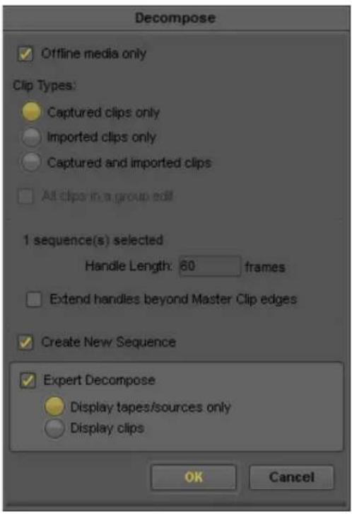
- To preserve clips that already have existing media files, select "Offline media only."
Do not select this option if you plan to decompose and recapture any material in the sequence or sequences that has available media. - Select other options for the types of clips to decompose: captured only, imported only, captured and imported, or all clips in a group edit.
- Click the Handle Length text box and type the number of additional frames you want to capture at the heads and tails of the new master clips.
This provides enough overlap for trimming and adding transition effects.

If you attempt to trim or add effects with no handles, you receive an error message notifying you that there is insufficient media.
- (Option) Select "Extend handles beyond master clip edges" to allow the handles to extend before the beginning and after the end of the original master clip.
When you batch capture, deselecting this option prevents capturing across a discontinuous timecode error.
For example, if the starting timecode for a master clip is 1:00:10:00 and the resulting master clip after a decompose with handles causes the new master clip to begin at 1:00:09:00, batch capturing will fail if there are any timecode discontinuities between 1:00:09:00 and 1:00:10:00.
- (Option) If you want to create a copy of each selected sequence to use for the decompose, select Create New Sequence.
When the decompose process starts, your Avid editing application creates a duplicate of each of the selected sequences, named using the suffix .Decomposed.xx. For example, the duplicate of a sequence named MySequence is named MySequence.Decomposed.01. Your Avid editing application decomposes the duplicate sequences, and the original sequences remain unchanged.
- (Option) If you want to use Expert Decompose, select Expert Decompose, and then select one of the following options to control how information displays in the Expert Decompose dialog box:
Option Description
| Display tapes/sources only | An item appears in the Expert Decompose dialog box for each tape or other source represented in the selected sequences. That is, this option groups all clips from each unique source into one item. |
| Display clips An item | appears in the Expert Decompose dialog box for each clip in the selected sequences. Depending on the number of sequences you have selected and the length of the sequences, this might result in a very long list of items in the Expert Decompose dialog box. |
9. Click OK.
If you selected Expert Decompose in step 8, the Expert Decompose dialog box opens. For information on how to use this dialog box, see “Using Expert Decompose” on page 249.
New master clips appear in the bin, named using the suffix .new.xx. You can now sort and select these clips like all other objects in the bin.

Your Avid editing application selects a resolution for each new clip that is appropriate for the target format you select in the Expert Decompose dialog box. If the target format matches the current project type, your Avid editing application uses the capture resolution set in the Media Creation settings. Otherwise, your Avid editing application uses the resolution of the original clip or the default resolution for the project. The clip's resolution is a default that you can override when you recapture.
- Proceed with the recapturing procedures described in "Batch Capturing Clips" on page 241.
Using Expert Decompose
If you select the Expert Decompose option in the Decompose dialog box, the Expert Decompose dialog box opens before the decompose process begins.
In the Expert Decompose dialog box, you can:
- View information about the tapes/sources or clips in the sequences you are decomposing.
If you select “Display tapes/sources only” in the Decompose dialog box, a line of information appears for each tape or source used in the sequences you are decomposing, and the information columns display the name of each tape or source, the original video resolution of the clip, the source frame rate, and the edit frame rate.
If you select "Display clips" in the Decompose dialog box, a line of information appears for each source clip represented in the sequences you are decomposing, and an additional column displays the name of each clip.
- Sort the information in any of the columns.
- Select the tapes/sources or clips that you want to decompose.
- Select the target format at which you want to recapture the decomposed tapes/sources or clips.
The following illustration shows the Expert Decompose dialog box as it might appear if you select sequences that contain clips of a variety of different formats and then select “Display clips” in the Decompose dialog box. In some cases, the edit rate for a clip differs from the source rate.

For more information, see “Understanding Decompose and Expert Decompose” on page 245 and “Decomposing Sequences” on page 247.
To sort or reverse sort a column of information:
Right-click the column heading for any column, and then select one of the following:
Command Description
Sort Column Sorts the information in order, for example, alphabetically A to Z.
Command Description
| Reverse Sort Column | Sorts the information in reverse order, for example, reverse alphabetically Z to A |
To select or deselect a single tape/source or clip to decompose:
Click the check box for the tape/source or clip in the Decompose column.
To select or deselect multiple tapes/sources or clips to decompose:
- In any of the information columns, click the first tape/source or clip you want to select.
-
Do one of the following:
To select a contiguous group of tapes/sources or clips, Shift+click the last tape/source or clip you want to select.
Your Avid editing application selects the last tape/source or clip and all the tapes/sources or clips between the first and last.
To select or deselect additional tapes/sources or clips from anywhere in the list, Ctrl+click (Windows) or Command+click (Macintosh) on each tape/source or clip you want to select or deselect. -
Right-click on any selected item, and then select one of the following:
Command Description
| Include in Decompose Selects the check box in the Decompose column for each of the selected items. |
| Exclude from Decompose Deselects the check box in the Decompose column for each of the selected items. |
To deselect all selected tapes/sources or clips:
▶Click below the last item in any of the information columns.
To select the target format for a tape/source or clip:
▶ Select a format from the menu for the tape/source or clip in the Target Format column.
The available target formats vary depending on the source formats.
Some source formats can only be recaptured in their original format. For these formats, the entry in the Target Format column is only for your information, and you cannot select a different format.
For more information, see “Expert Decompose” on page 245.
To proceed with the decompose process:
▶Click OK.
Recapturing a Sequence Without Using Decompose
When you recapture a sequence without using decompose, your Avid editing application creates new master clips and captures new media in a single operation.
For more information on recapturing a sequence with and without decompose, see “Understanding Recapturing” on page 243 and “Understanding Decompose and Expert Decompose” on page 245.
To recapture a sequence:
- Select the proper Capture settings and set up the capture tools, as described in “Preparing for Capture” on page 159.
- Open or activate the bin that stores the sequence.
- Select Bin > Go To Capture Mode.
- Select the sequence you want to recapture.
- Select Clip > Batch Capture.
The Batch Capture dialog box opens.
- To preserve clips that already have existing media files, select “Offline media only.”
Deselect this option if you plan to recapture the entire sequence.
- (Option) Select "All clips in a group edit."
- Click the Handle Length text box and type the number of additional frames you want to capture at the heads and tails of the new master clips.
This provides enough overlap for trimming and adding transition effects.

If you attempt to trim or add effects with no handles, you will receive an error message notifying you that there is insufficient media.
- (Option) Select "Extend handles beyond master clip edges" to allow the handles to extend before the beginning and after the end of the original master clip.
When you batch capture, deselecting this option prevents capturing across a discontinuous timecode error.
For example, if the starting timecode for a master clip is 1:00:10:00 and the resulting master clip after a decompose with handles causes the new master clip to begin at 1:00:09:00, batch capturing fails if there are any timecode discontinuities between 1:00:09:00 and 1:00:10:00.
- Click OK.
Your Avid editing application prompts you to load the first tape.
- Load the tape into the tape deck if you have not already done so.
- Click Mounted to indicate to the system that the correct tape is loaded and ready for capturing.
A dialog box opens.
- Click OK to confirm the tape and deck entries.
Your Avid editing application captures each clip from the tape, in start timecode order. If another source tape is needed, your Avid editing application prompts for the tape. You can stop the batch-capturing process at any time by clicking the Trash button in the Capture tool. A message box notifies you when batch capturing finishes. The new master clips appear in the bin, and associated media files exist on the targeted drive or drives.
Alternate Source Capture
Alternate source capture allows you to choose a different source name (Tape) and timecode (Start) to use when you perform a batch capture. This is helpful when the clips used in your sequence are from a submaster source tape that is different than the original master tape. For example, if during production you record RGB to HDCAM SR and then make color corrected selects to HDCAM for the offline workflow, when mastering, it is best to go back to the original master tape and color correct from the HD RGB sources. When you create the original HDCAM tapes, the metadata displays as:
TAPE Color corrected submaster
START Timecode from color corrected submaster
Camroll Tape name from original field HDCAM SR master
Auxiliary TC 1 Timecode from original field master
When you perform a batch capture of the Timeline or source clips, you can select and frame accurately batch capture from either the HDCAM submaster or the HDCAM SR master.
You can also use an alternate tape name if the original tape name was incorrectly logged. You can use any custom column in the bin as a source name when you batch capture in addition to Labroll, Camroll, and Soundroll, or you can correct for timecode offsets and store them in the Auxiliary TC column and batch capture from that.

When you use an alternate tape source, the tape does not have to display in the list of tapes. You can create a temporary tape for the capture process and remove it from the list once the batch capture is complete.

For more information and additional steps to batch capture, see “Preparing for Capture” on page 159 and “Batch Capturing Clips” on page 241.
To batch capture with an alternate source:
- In a bin, select the clips you want to batch capture.
- Select Tools > Capture to open the Capture tool.
The Capture Tool opens. - Open the bin that stores the clips you want to batch capture.
- Select the clips to batch capture:
-
Select Clip > Batch Capture.
The Batch Capture dialog box opens. -
Under the Alternate Source Options (Advanced), select the type of timecode from the Timecode Column menu that you want to batch capture from.
Options depend on your project type. Timecode options can include: Start, Auxiliary TC1-TC5, Sound TC.
If you choose a timecode other than Start, a message displays informing you that an Alternate Source is enabled.
- Select the tape source from the Source Column menu that you want to batch capture from.
Options depend on your project type and custom columns. Tape options can include: Tape, Camroll, Labroll, Soundroll, Custom Tape.

To set the Timecode Column and Source Column menu selections back to the defaults (Start and Tape), click Reset.
- Click OK.
If any clips you select do not have the alternate source options you selected (for example, a clip does not have an Auxiliary timecode), a message displays and asks you if you want to skip those clips. Click Continue to continue with the batch process and skip those clips.
- A message opens and asks you to mount the (alternate) tape.
You can choose to mount the tape or skip this particular clip.
- Load the tape into the tape deck and click Mounted.
The deck rolls to the alternate source timecode and begins the capture process.
Your Avid editing application captures each clip from the alternate source timecode and tape.
Using Capture Function Keys
Several function keys are mapped to specific capture functions when the Capture tool is active. When you are not in Capture mode, these keys operate with their default keyboard shortcut mappings. For more information, see "Shortcuts" in the Help.
The following table lists the default functions. You can change the functions in the Keys tab of the Capture Settings dialog box.
Press To
F1 Mark the beginning of the subclip while capturing.
F2 Mark the end of the subclip while capturing.

Capturing on-the-fly can cause incorrect pulldown and stuttering playback. Do not use the F1 or F2 keys for capturing 24-fps film that was transferred to NTSC video unless you have set the correct pulldown phase. See “Setting the Pulldown Phase” on page 149.
F3, Add a marker to the current frame while capturing. Each Function key adds a different F5 through color marker. See “Adding Markers On-the-Fly While Capturing” on page 259. F12
F4 In Capture mode, start the capture process. During capture, end a comment for a marker.
In Log mode, press once to mark an IN point. Press again to mark an OUT point to log the clip in the bin.
To change function key commands for capturing media:
- Double-click Capture in the Settings tab in the Project window.
The Capture Settings dialog box opens.
- Click the Keys tab.
- Click the key you want to map, and then select the new function from the menu.


The Start Capture function is not included in the key menus. F4 always starts capture. You can map an additional function to F4 to use after capture starts; End Marker Entry is the default.
- Click OK.
Handling Errors During the Capture Process
You can log errors that occur during the capture process to the Console window. If you are not logging, you can respond to errors if they occur.
For more information about the Console window, see "Using The Console Window" on page 115.
To enable or disable logging to the Console window during capture:
- Double-click Capture in the Settings tab in the Project window.
The Capture Settings dialog box opens.
- Click the Batch tab.
-
Select or deselect "Log errors to the console and continue capturing."
-
If “Log errors to the console and continue capturing” is selected, when you batch capture and your Avid editing application encounters an error, it aborts the clip, enters error comments into the Console, and continues capturing the next clip.
-
If “Log errors to the console and continue capturing” is not selected, a message appears and your Avid editing application pauses if an error occurs while capturing. If this happens, use the last procedure below.
-
Click OK.
To open the Console window:
▶Select Tools > Console.
To respond when your Avid editing application pauses during capture and is not logging to the Console:
- Click Try Again to retry the operation.
The clip might capture successfully.
If the clip does not capture the second time you try, the error message appears again.
-
Click Next Clip to bypass the clip that caused the error and continue batch capturing any remaining clips, or click Abort to cancel the entire batch capturing process.
-
Note all errors, messages, and steps you have taken. Try to troubleshoot the problem on your own, or contact Avid Customer Support.
Creating Subclips While Capturing
You can create subclips on-the-fly while capturing, or you can create timed subclips. The maximum number of subclips you can generate while capturing a clip is 100.
You instruct your Avid editing application to create a timed subclip automatically when you press a function key that you have mapped to the Timed Subclip button. Your Avid editing application creates IN and OUT points at predetermined intervals before and after the point you identify in the source media by pressing the button. For information on mapping capture functions to function keys, see “Using Capture Function Keys” on page 255.
For information about creating subclips after capturing, see “Creating Subclips” on page 520.
You should be aware of the following while creating subclips while capturing:
- When you create subclips in 24p or 25p projects, they are always “hard” subclips. You cannot trim past the edges of the subclip when adjusting transitions and edits. Hard subclips prevent film-tracking information errors for editing and cut lists.
- For NTSC film-to-tape transfers, you must log the correct pulldown phase before you create subclips. For more information, see “Setting the Pulldown Phase” on page 149.
- If your Avid editing system is an asset manager client in an OMF workgroup, and you are capturing with shared volume segmentation (“chunking”) enabled, see your Avid shared storage documentation for details on the capture procedure.
- If your Avid editing system is an asset manager client in an MXF/AAF workgroup, you cannot create subclips while capturing media using the Capture tool. However, you can use the Frame Chase editing feature when capturing media from a supported external device using Avid Interplay Transfer. For more information about using Frame Chase editing, see “Using Frame Chase Editing” in Avid Interplay Best Practices.
To create a subclip on-the-fly:
- Start capturing.
- At the point where you want the subclip to begin, press the F1 key.
This highlights the subclip IN point. - While you capture, you can type a name for the subclip. Press the Tab key to type comments about the clip.
- When you want the subclip to end, press the F2 key.
This highlights the subclip OUT point.
- (Option) Press the F2 key repeatedly as you search for the end point of the subclip.
Your Avid editing application accepts the last occurrence as the end point.
You can also press the F1 key at any time before pressing F2 again to remove the previous subclip marks and to start a new subclip IN point.
The subclip appears in the target bin when you stop capturing. When capture is complete, a number appears between the subclip indicators to show the number of subclips created.
To set the duration of a timed subclip:
- Double-click Capture in the Settings tab in the Project window.
The Capture Settings dialog box opens. - Click the Keys tab.
-
Click OK.
-
Enter the time in minutes and seconds to be used by the timed subclip in the Before mark (M:SS) and the After mark (M:SS) text boxes.
To create a timed subclip:
- Start capturing.
-
At the point where you want to start a timed subclip, press the mapped function key.
This highlights the subclip IN and OUT points, and your Avid editing application creates the subclip automatically. -
While your Avid editing application is capturing, you can type a name for the subclip. Press the Tab key to type comments about the clip.
Adding Markers On-the-Fly While Capturing
You can use function keys to add markers on-the-fly while capturing. When the Capture tool is active, eight colored markers are mapped to the F5–F12 function keys on the keyboard, and the End Marker Entry key is mapped to F4. The markers override any other functions mapped to these keys.
If your Avid editing system is an asset manager client in an OMF workgroup, and you are capturing with shared volume segmentation (“chunking”) enabled, see your Avid shared storage documentation for details on the capture procedure.
If your Avid editing system is an asset manager client in an MXF/AAF workgroup, you cannot create markers while capturing media using the Capture tool. However, you can use the Frame Chase editing feature when capturing media from a supported external device using Avid Interplay Transfer. For more information about using Frame Chase editing, see “Using Frame Chase Editing” in Avid Interplay Best Practices.
For more information about markers, see “Using Markers” on page 523.
To add a marker to a frame while capturing:
- Start capturing.
- Watch the playback of the footage in the monitor, and press one of the marker keys (F5–F12) when you see the shot or frame with which you want to associate a marker.
A default name and number for the marker appear in the Name text box in the Capture tool. - While you capture, you can add comments for the marker. Press the Tab key to move the cursor to the Comments text box, and type your comment.
- When you finish adding your comment for the marker, press the F4 key (End Marker Entry).
The Name and Cmnt (Comment) text boxes revert to association with the master clip or the subclip being captured. Marker comments appear in the Markers window. - To see the marker comments, open the Markers window as described in “Viewing Markers in the Markers Window” on page 532.
Naming a New Tape from the Keyboard While Capturing
You can name a new tape without taking your hands off the keyboard.
To create a new tape name by using a keystroke in Capture mode:
-
Select Tools > Capture.
The Capture tool opens. -
Do one of the following:
▶Load a tape in the deck.
▶Click the Source Tape Display button.
The Select Tape dialog box opens.
- Press Ctrl+N (Windows) or Command+N (Macintosh).
A new tape name text box opens.
-
Type the new tape name.
-
Press Enter (Windows) or Return (Macintosh) to register the tape name.
-
Press Enter (Windows) or Return (Macintosh) or click OK to close the Select Tape dialog box.
Controlling Decks from the Keyboard
You can use the J-K-L keys to control a deck from the Capture tool, Digital Cut tool, and Deck Controller window.
The J-K-L keys work in the same way as they do in the Source and Record monitors. See “Playing Footage with the J-K-L Keys (Three-Button Play)” on page 512.
Press To
K Stop the deck.
L Shuttle the deck at 1x, 2x, 3x, 5x, 8x, 16x, or 24x normal speed.
J Shuttle the deck at -1x, -2x, -3x, -5x, -8x, -16x, or -24x normal speed.
K+L Shuttle the deck at 0.25x normal speed.
J+K Shuttle the deck at -0.25x normal speed.
The following restrictions apply:
- You must select the Capture tool, Digital Cut tool, or Deck Controller window for the keys to be active.
- Single-field stepping is not supported.
- If you remap the function of the J-K-L keys, you can no longer control decks with those keys.
Ejecting Tapes with a Button or Key
If you click the Eject button and eject a tape, you can bring the fact that the tape must be changed to the attention of any tape operator in a remote machine room.
To eject tapes by using a button:
- Select Tools > Command Palette.
- Click the Play tab.
- Select Active palette.
- Click the Eject button.

You can map the Eject button to any button on the Tool palette or any key on the Keyboard palette. See “Mapping User-Selectable Buttons” on page 112.
Using Dolby E Media
Dolby ^® E is an audio coding technology created by Dolby Labs that compresses up to 8 channels of audio and metadata into 2 channels. This enables the distribution of multichannel audio within a stereo track or on two mono tracks which you can then use in your Avid editing project.
Dolby E support is available for Avid systems using the following Avid hardware: Avid Nitris DX and Avid Mojo DX.
The workflow for using Dolby E clips includes the following steps:
- Select the “Keep Dolby E Material Safe” setting in the Audio Project Settings dialog box to ensure the capture of Dolby E media.
-
Use the Capture tool to bring Dolby E media into your project. A Dolby E Safe button in the Capture tool indicates that your audio settings protect Dolby E media information.
-
Add the Dolby E clip to your sequence, and edit the video and audio. Your Avid editing application maintains synchronization between audio and video as long as you do not convert or modify the Dolby E clip.
- When you finish editing, output the sequence. The Dolby E track preserves the encoded data and can be restored to the original multichannel audio.
If editing the sequence modifies your audio settings in a way that prevents the Dolby E information from being preserved, you cannot output or mix down your sequence with the original Dolby E metadata. You should reset your Audio Project settings before you output your sequence by an export operation or by using the Digital Cut tool, or if you mix down your sequence.

If you are working in a film project, you cannot use pulldown settings when you capture your media if you want to use Dolby E material. Avid does not support capturing Dolby E media with audio pulldown because pulldown interferes with the preservation of Dolby E information.
Selecting Dolby E Safe Settings
You can automatically set your Avid editing system to protect Dolby E information during capture. Selecting Dolby E safe settings changes the following options in the Audio Project Settings dialog box and the Passthrough Mix tool:
Location Option Setting
| Audio Project Settings (Main tab) Sample Rate 48 kHz | ||
| Audio Project Settings (Main tab) Bit Depth 24 bit | ||
| Audio Project Settings (Main tab) Convert Sample Rates When Playing Never | ||
| Audio Project Settings (Input tab) Input Gain Slider 0 dB (unity gain) | ||
| Audio Project Settings (Input tab) Sample Rate Conversion Never | ||
| Audio Project Settings (Input tab) Output Sync During Passthrough Same as Audio In | ||
| Audio Project Settings (Output tab) | Mix Mode Selection | Direct Out |
| Passthrough Mix tool | Input Mix Mode | Direct Out |
| Passthrough Mix tool | Input Gain Slider 0 dB (unity gain) | |
When you output your sequence either by selecting an export operation or by using the Digital Cut tool, or when you mix down the sequence, you must reset your Audio Project settings if a change in your sequence prevents the safe output of Dolby E information.
To select Dolby E safe settings:
- In the Project window, click the Settings tab, and then double-click Audio Project. The Audio Project Settings dialog box opens.

- Click the Main tab.
- Click Keep Dolby E Material Safe, and select Yes.
If you modify your sequence to change any of these settings, the Keep Dolby E Safe setting automatically changes to No. You can reset the settings by selecting Yes.
Capturing Media with Dolby E Information
The Capture tool includes a Dolby E Safe button in the Message bar that indicates if your audio settings protect the capture of Dolby E material. The button displays blue when the Keep Dolby E Material Safe option in the Audio Project Settings dialog box is set to Yes. If your audio settings do not protect Dolby E information, the button displays yellow.

Capture tool with blue Dolby E Safe button

The Dolby E Safe button appears only on systems using the following Avid hardware: Avid Nitris DX and Avid Mojo DX.
To capture media while protecting Dolby E information:
- In the Main tab of the Audio Project Settings dialog box, Click Keep Dolby E Material Safe, and select Yes.
- Select Tools > Capture.
The Capture tool opens. - Check to make sure the Dolby E Safe button displays blue.
If the Dolby E Safe button displays yellow, reset the Dolby E Safe settings in the Audio Project Settings dialog box (see “Selecting Dolby E Safe Settings” on page 262). - Capture your media using the appropriate capture method. For more information, see “Capturing Media” on page 223.
Delaying Audio During Capture
Sometimes the source from which you are capturing provides an audio signal that is one or more frames ahead of the video. For example, the Panasonic AG-DVX100 DV camcorder always records audio one frame ahead of the video. Also, a timebase corrector (TBC) or other video processing device on your input signal might introduce fixed frame delays of video.

If the input signal is not DV when you choose your IN point, the audio that lines up with the IN point should remain in sync with the captured media. The video is what shifts in the captured media. If the input signal is a DV signal however, then the audio shifts.
If the audio you are capturing is always at a fixed offset ahead of the video, use the Delay Audio feature to correct this problem and produce a master clip with correct A/V sync.
To offset your audio:
- Select Tools > Capture.
- Select the number of offset frames from the Delay audio menu.
- Capture your material.
- Play the captured media to verify that the audio and video are in sync.
Live Capturing with External Timecode
LTC (longitudinal or linear timecode) from an external source lets you capture from multiple sources at the same time as recording to tape. If your facility has a central timecode generator you can use that clock to send identical timecode to all systems. You can run this timecode output directly to your Avid system through the LTC IN connection available on some Avid input/output hardware.
External timecode is especially useful for live events, dramatic multicamera shows, and video material coming in on routers that do not support timecode through normal RS-422 communication. You can start editing immediately after the shoot without waiting to capture from the backup reference tapes.
If you are capturing 24p film, however, you need to account for the pulldown phase, which allows for 24p capture to have the same behavior as a video rate. Your selection in the Set Pulldown Phase of Timecode (A, B, X, C, or D) area in the Film and 24p Settings dialog box determines what type of pulldown the system uses during the 24p capture. Only non-drop-frame timecode is supported with the Pulldown Phase of Timecode option.
Setting IN and OUT points is especially useful if you are taking a feed from a source based on a time-of-day timecode generator. Your Avid editing application begins to capture when the time of the external timecode source matches the IN point, and stops when the external timecode matches the OUT point.

You can log an event ahead of time and it automatically starts recording that signal when the internal clock or external LTC arrives at that timecode. For example, if you log a clip at 14:00:00:00 to 14:30:00:00 sometime before 2:00 pm, the capture starts at 2:00 pm and ends at 2:30.
To capture with external timecode:
- If you are capturing 24p film, in the Film and 24p settings dialog box, select Set Pulldown Phase of Timecode 00:00:00:00.
- Select a pulldown cadence that matches the pulldown cadence of the incoming signal. For more information, see “Setting the Pulldown Phase” on page 149.
- Click OK.
- Select Tools > Capture.
The Capture tool opens.
- Click the Toggle Source button until the No Deck icon appears.

Toggle Source button showing No Deck icon in the Capture tool
- Click the TC Source menu, and select LTC Input.
The menu contains two other choices:
- Internal: Uses internal system timecode.
- Auto Detect: Detects LTC input by default. If the LTC input is deactivated, the Capture tool automatically switches to internal timecode. If the LTC input is reactivated, the Capture tool switches back to LTC input.
LTC is only available with some Avid input/output hardware devices. If LTC is not available for your configuration, the LTC Input option is grayed out.
- Capture by using any of the techniques described elsewhere in this chapter.
If you notice your captured material is consistently one or more frames off, use the “Latency for external timecode mode” option in the Capture Settings dialog box to fix the problem. See “Capture Settings” on page 1361.
Capturing to the Timeline
You can capture footage directly from tape to a sequence loaded in the Timeline in one step, bypassing several steps such as organizing and reviewing clips, marking edit points, and performing edits.
By default, your Avid editing application edits the tracks you select for capturing to the corresponding tracks in the Timeline. You can patch the captured footage to any track in the Timeline.

You can also patch tracks in the Timeline in the same way you patch tracks when editing from the Source monitor. See “Patching Tracks” on page 713.
Only tracks that are enabled in the Timeline are available for patching. Other tracks appear dimmed in the menu.
To capture to the Timeline:
- Prepare for capturing.
See “Preparing for Capture” on page 159.
- Set options in the Capture Settings dialog box:
a. Click the Settings tab in the Project window.
b. In the Settings list, double-click Capture.
The Capture Settings dialog box opens.
c. Click the Edit tab.
d. Select "Enable edit to timeline (splice, overwrite)".
e. Set the handle length (the amount of footage you want to capture before and after the IN and OUT points of the clips).
f. Click OK.
-
Load a sequence into the Record monitor.
-
(Option) Patch tracks you are capturing (source tracks) to the tracks in your sequence (record tracks):
a. In the Capture tool, click and hold the Track Selector button for the track (video, data, or audio) you want to patch.
There is only one data track to select, you cannot patch a data track to any other track.
b. From the menu, select the track to which you want to patch the captured footage.

Track Selector button and menu in the Capture tool (left), and result displayed in the Timeline (right)
-
Mark an IN point in the sequence or move the position indicator to where you want the edit to take place.
-
Mark the source material you want to capture by using the Capture tool logging controls.
For more information, see "Logging with Avid-Controlled Decks" on page 139.
- (Option) Mark an OUT point based on the following:
If you are recording to the middle of a sequence in the Timeline, mark both IN and OUT points for frame accuracy.
If you are recording to the end of a sequence, you can mark just an IN point and then mark the OUT point later on-the-fly.
- Click the yellow Splice-in button or the red Overwrite button in the Capture tool to select the type of edit.

Record button (left) and Splice-in and Overwrite buttons (right) in the Capture tool
-
Click the Record button to begin recording.
-
If you did not mark the OUT point in advance, click the Record button again when the footage reaches the appropriate frame.
If you already marked an OUT point, recording stops automatically.
When capturing ends, the clip appears in place in the sequence, and a master clip appears in the bin.
If your capture includes ancillary data, a data track appears in the Timeline.
Capturing Video Without Pulldown into a 24p NTSC Project
Film-to-tape transfers that are made without using pulldown can be captured directly into a 24p project. This feature is useful when special effects are generated on a frame-to-frame basis to tape, and need to be integrated into a 24p project.
Before capturing the footage, click the Film to Video Transfer menu in the Film and 24p Settings dialog box, and select Video Rate. The Film-to-Video Transfer setting lets you specify the type of film-to-tape transfer you are capturing. For more information, see “Capture-Related Settings for Film and 24p Projects” on page 176.

For normal 24-frame capture, click the Film to Video Transfer menu in the Film and 24p Settings dialog box, and select Pulldown.
Remote Play, Capture, and Punch-In
You can use an external edit controller with an Avid editing system for the following functions:
Function Description
Remote Capture Controls the capturing of media into an Avid editing system while using an edit controller. Remote Capture lets you record and stop.
Remote Play Controls sequences loaded in the Record monitor and played back through an edit controller to the edit room, along with other sources. Remote Play lets you cue, play, and stop.
Remote Punch-In Controls the recording of audio into an Avid editing system while using an edit controller. Remote Punch-In lets you cue, play, record, and stop.
When you select Remote Capture or Remote Punch-In in the Remote Play and Capture Settings dialog box, your Avid editing system performs like a VTR and waits for an external controller to operate the capture functions.

You must be in Deck Offline mode to use Remote Capture. For information on Deck Offline mode, see “Capturing from a Non-Avid-Controlled Deck” on page 232.
To use Remote Play and Capture, you must connect a supported controller (any controller that uses Sony ^® serial control protocol) to your system by using a special Avid 9-pin VTR emulation cable and a serial adapter.

If a message appears stating that the Avid Serial Driver is not installed for Remote Play and Capture, make sure the correct serial driver is installed on your system. If you are running Avid Media Browse ^™ and using the Remote Play and Capture option, you need to run your Avid editing application with the Microsoft driver. If you are running your Avid editing application without Avid Media Browse, you need to install the Avid serial driver.
Selecting Remote Play and Capture Settings
To open the Remote Play and Capture Settings dialog box:
- Double-click Remote Play and Capture in the Settings list of the Project window. The Remote Play and Capture Settings dialog box opens.

- Click the Mode menu, and select Remote Play, Remote Capture, or Remote Punch-In. For information about each option, see “Remote Play and Capture Settings” on page 1428.
Enabling Remote Capture
Before you enable Remote Play and Capture, ensure your edit controller is properly connected.

The Remote Play and Capture command behaves like a Local/Remote switch on a playback device, with the VTR in Local mode by default when you start your system.
To enable Remote Capture:
- Double-click Communication (Serial) Ports in the Settings list of the Project window. The Communication (Serial) Ports tool opens.
- Select Remote Play and Capture > port.
- Close the Communication (Serial) Ports tool.
Your Avid editing application saves the setting as a Site setting, effective for all projects. - Double-click Remote Play and Capture in the Settings list of the Project window.
The Remote Play and Capture Settings dialog box opens. - Select Mode > Remote Capture.
- Select Device Code > device.
- Specify the time (measured in frames) it takes the deck to start playing from a cued position in the Runup area.
- Select Special > Remote Play and Capture when you are ready to capture.
A check mark appears next to the command to indicate that the system is ready. A yellow outline appears around the Play button in the Source/Record monitor to indicate that Remote Play and Capture is active. - Select Tools > Capture.
The Capture tool opens. - Select the tracks onto which you want to capture by clicking the Channel Selection buttons.
- Choose Bin > bin.
- Click the Toggle Source button until the Deck Offline icon appears.
- Control capturing from the controller.
Enabling Remote Play
Remote Play lets you control sequences through an edit controller. You can play, cue, and stop your sequence from the edit controller.

Avid recommends that you do not inhibit preloading under normal circumstances. For more information about the inhibit preloading option, see “Remote Play and Capture Settings” on page 1428.
To enable Remote Play:
- Double-click Remote Play and Capture in the Settings list of the Project window. The Remote Play and Capture Settings dialog box opens.

- Select Mode > Remote Play.
- Select Device Code > device.
- Select Special > Remote Play and Capture when you are ready to use your system for playing.
A check mark appears next to the command to indicate that your system is ready. A yellow outline appears around the Play button in the Source/Record monitor to indicate that Remote Play and Capture is active. The Remote Play and Capture command behaves like a Local/Remote switch on a playback device, with VTR in Local mode by default when you start your system.
- Use the Play, Cue, and Stop buttons on the edit controller to control a sequence loaded in the Record monitor.
At this time, you cannot fast-forward, rewind, or shuttle and jog from the edit controller.
Setting up Your System for Remote Punch-In
Before you enable your Serial Remote, you must set the following options on your edit controller:
- 049 — Send Record In and Out to Machine set to 1=Yes
• 065 — Locate Type set to 0=Locate - 077 — Extended Status Request set to 1=Off
In addition, all devices controlled by the controller must be genlocked, and your Avid editing system must be configured as the Master device. For more information on configuring the Serial Remote, see the documentation for your controller.
To record audio using Remote Punch-In:
- Double-click Communication (Serial) Ports in the Settings list of the Project window.
The Communication (Serial) Ports tool opens. - Click the Remote Play and Capture menu, and select the appropriate port.
- Close the Communication (Serial) Ports tool.
Your Avid editing application saves the setting as a Site setting, effective for all projects. -
Double-click Remote Play and Capture in the Settings list of the Project window.
The Remote Play and Capture Settings dialog box opens. -
Select Mode > Remote Punch-In.
-
Click the Device Code menu, and select the appropriate device.
-
(Option) Specify other settings as described in “Remote Play and Capture Settings” on page 1428.
-
Click OK.
- Select Clip > Remote Play and Capture when you are ready to use your system for capturing.
A check mark appears next to the command to indicate that your system is ready. A yellow outline appears around the Play button in the Source/Record monitor to indicate that Remote Play and Capture is active.
The Remote Play and Capture command behaves like a Local/Remote switch on a playback device, with the VTR in Local mode by default when you start your system.
- Select Tools > Audio Punch-In.
The Audio Punch-In tool opens. Some of the features in the Audio Punch-In tool — such as the preroll and postroll options — do not appear when you open the tool in Remote Play and Capture mode.
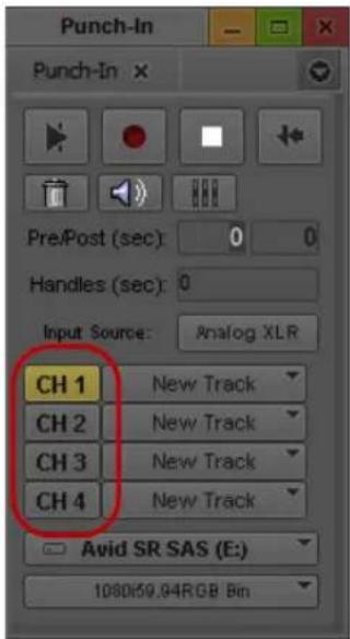
Input Channels buttons in the Audio Punch-In tool
- Select the tracks you want to record to by clicking the Input Channels buttons.
- Load a sequence in the Source monitor.
- Using the controls on the external controller, set an IN point in the Timeline.
If you set the IN point at the first frame of the sequence, you must add filler to the start of the sequence equal to the amount of preroll. This allows your system to sync lock your Avid editing application to the external controller. Setting an OUT point is optional.
- Control recording from the controller.
Remote Punch-In does not use preroll or postroll settings, and it does not initiate a loop playback or audition playback prior to recording. Remote Punch-In begins recording audio to the selected channels as soon as you start the record operation.
Relinking Clips by Key Number
The film-tape-film-tape (FTFT) relinking feature lets you re-create an offline, film-originated sequence as a final finished sequence by using the key numbers of the original film footage. During the offline stage, you capture and edit footage that was transferred to tape through a one-light or best-light telecine transfer (the first FT). During the finishing stage, you batch capture, relink by key number, and edit footage that was transferred through a second timed, color-corrected telecine transfer (the second FT).
Alternatively, if you are finishing a sequence in an online suite and need only an EDL, you do not need to batch capture the footage. Just import the new shot log, relink to the offline items, and then create the EDL.
Relinking by key number eliminates the need for the telecine transfer facility to match the timecode and pulldown of the second transfer to the timecode of the first transfer.

For more information about relinking, see “Relinking Media Files” on page 467.

Duplicate your sequence before relinking. If you relink to the original sequence, you will lose your links to the original media.
To relink clips by key number:
- After you finish editing the offline sequence, use the FilmScribe ^™ application to create a pull list of the clips used in the sequence.
For information on using FilmScribe, see the FilmScribe documentation.
- Have the telecine facility use the pull list to pull selects from the original negative and to transfer picture-only footage by using a timed, color-corrected telecine process.
You do not need to transfer audio again. The telecine facility supplies a new shot log file along with the transfer tape.
-
In your original project, create a new bin.
-
Duplicate the edited offline sequence and move it to the new bin.
At this point, the duplicate sequence still links to the original media.
- Process the new log file through ALE and import it into the bin that holds the duplicated sequence.
For more information, see “Using Avid Log Exchange to Prepare Log Files for Import” on page 118 and “Setting the Pulldown Phase” on page 149.
- (Option) Batch capture the clips imported from the new log file. Select 1:1 or another high-quality resolution.
For more information, see "Batch Capturing from Logged Clips" on page 239.
- Select the duplicated sequence and the new clips.
- Select Clip > Relink.
The Relink dialog box opens.
![Relink Relink selected items to: Media on drive: All Available Drives Master clips Tip: To bring master clips online, first try loading media databases All other items Sequences, sub clips, group clips, etc. Relink only to media from the current project Selected items in ALL open bins Allow relinking to offline items Relink by: Key Number [KN Start] - video only Allow relinking of imported/AMA clips by Source File name Version Separator: Allow relinking between tape and file based media Match case when comparing tape and source file names Video Parameters Relink to: Video format of current project only (1080/59.94) Relink method: Highest Quality Relink if quality: Different type of quality Format: 1080/59.94 Resolution: AVIClary-50-MVF If no match is found: Use Conversion Create new sequence (1 sequence selected) OK Cancel](/content/2026/05/883817/images/fcac1a4fbdbb9a7f8b7ec8f9a1dc38b32902dc5bbd74a0cd2744312a9c5c97a4.jpg)
- Select Relink > Key Number [KN Start] - video only.
- Select "Relink all non-master clips to selected online items."
-
(Option) If you did not batch capture the original clips, select "Allow relinking to offline items."
-
In most cases, select "Relink only to media from the current project."
Deselect this option if you know the new clips were captured with a different project name. Also, if the sequence does not relink to the new clips, try deselecting the option and relinking again.
- Click OK.
The new clips link to the sequence.
If you duplicated the offline sequence, the offline sequence is still linked to the original clips. If you did not duplicate the sequence, you relink it to the original clips.
To relink a sequence to the original clips:
- Duplicate the sequence.
- Create a new bin and move the sequence to the bin.
- Locate the original clips. Look for a bin with the original clips, or use the Media tool to locate the original clips.
For information on the Media tool, see “Using the Media Tool” on page 443. - Copy the clips to the bin that contains the duplicated sequence.
- Select the sequence and the original clips.
- Relink the clips by key number.
Modifying the Pulldown Phase After Capturing
If you have captured film-originated clips (NTSC transfer only) that seem to stutter, the problem might be an incorrectly logged pulldown phase (the video frame at which the master clip starts: A, B, X, C, or D). You log this pulldown phase in the “Pullin” column of a bin. To solve the problem, you need to determine the correct pulldown cadence of the frame, modify the clip information, and recapture the clip.

You can also determine the correct pulldown phase from the original tape. See “Entering Pulldown Information” on page 151.
To check for an incorrect pullin frame:
- Look for a section of the clip that includes a series of frames with motion.
- Step through the clip frame by frame (using the Step buttons or another method) and look for two frames that have no movement.
If the pattern is two frames of movement followed by two frames of no movement, the pullin is incorrect.
To determine the correct pullin frame, use one of the following approaches:
If the source footage includes burn-in code with the pulldown phase, go to the start of the clip and look for the pulldown for the first frame.
If you want to maintain the start timecode for each clip, review the original tape field by field, using the procedure described in “Entering Pulldown Information” on page 151.
▶If you do not need to maintain the start timecode:
a. Step through the clip frame by frame (using the Step buttons or another method). Look for two frames that are identical (no movement).
b. Think of these frames as frames B and X of a four-frame series.
| A | B | X | D |
| A | B | C | D |
Incorrect sequence (top, no movement between B and X frames) and correct sequence (bottom)
Step backward (either one frame from the B frame or two frames from the X frame) to locate the correct A frame. Note the last digit of its timecode. Timecode for all A frames in the clip starts either with this digit or this digit plus 5. For example, if the A frame has the timecode 1:00:10:20, timecode for all A frames in the clip ends in either 0 or 5.
c. Compare these digits with the last digit of the start timecode (first frame) of the clip to determine the correct pullin.
For example, if the A frame ends in 0 or 5, and the start timecode ends in 4, the pullin is D.
d. If the pullin for the clip is the X frame, you need to modify the timecode to produce a number you can associate with a pullin.
For example, if the A frame ends in 0 or 5, and the start timecode ends in 2, the pullin falls on the X frame and you need to modify the timecode along with the pullin. Move forward one frame to create a start timecode ending in 3. Then you can change the pullin to C.

When you change the timecode of a clip, you lose the key number of the clip. You need to enter it in the bin and adjust it to match any changes to the timecode.
To modify the clip information after you determine the pullin frame:
- In a bin, select the clip you want to modify and press the Delete key.
The Delete dialog box opens.
- Deselect the option "Delete master clip(s)" and select "Delete associated media file(s)."
- (Windows only) Select the resolutions to delete.
- Click OK.
Your Avid editing application deletes the original media file.
- Make sure the clip is still selected. Press Ctrl+Shift and choose Unlink from the Clip menu.
The clip information is unlinked and you can modify it.
- Type the correct letter for the pulldown phase in the Pullin column. If necessary, type a new timecode and key number.
For multiple clips, you can use the Modify command or the Modify Pulldown Phase command. See “Modifying the Pulldown Phase Before Capturing” on page 154.
- With the new clip information in the bin, batch capture the clip.
See “Batch Capturing Clips” on page 241.
If the pulldown phase is accurate, the clip should play smoothly, with no repeated frames.
This method might not work for some clips that start with either an A frame or a D frame. If the clip still stutters after you modify it, modify the clip again. This time, if the pullin is A, change it to D. If the pullin is D, change it to A.
DV and HDV Scene Extraction
While you are capturing DV or HDV footage, the DV and HDV Scene Extraction feature lets you generate subclips and markers automatically, based on time-of-day (TOD) information contained in the DV or HDV format.
Discontinuities in the DV or HDV TOD metadata indicate each new take in a master clip or subclip shot on a DV or HDV camera. Using this feature, you can capture an entire DV or HDV tape as a single master clip and have your Avid editing application automatically locate all the takes for you, eliminating the need to log manually.
You can perform a DV Scene Extraction in two ways and an HDV Scene Extraction one way:
- Set up the DV or HDV Scene Extraction option before capturing. When capturing is performed, subclips and marker marks appear in the bin.
- Perform DV Scene Extraction after capturing. Select those clips in the bin for which you want to generate subclips and marker marks
You should be aware of the following:
- You can perform DV Scene Extraction on any existing clip or subclip in a bin that has TOD information breaks.
- DVCPRO format does not provide TOD metadata. You cannot use DV or HDV Scene Extraction with DVCPRO format.
- DV or HDV Scene Extraction does not work on non-DV or audio-only clips.
To set up DV and HDV scene extraction before capturing:
- Double-click Capture in the Settings list of the Project window.
The Capture Settings dialog box opens. - Click the DV&HDV Options tab.
- Select DV or HDV Scene Extraction, depending on your type of project.
- Select one of the following options:
Option Description
Add Markers Creates marker marks where the TOD information breaks occur while capturing.
Create Subclips Creates subclips where the TOD information breaks occur while capturing.
Both Creates subclips and marker marks where the TOD information breaks occur while capturing.
- Click OK.
- Select Tools > Capture and then click the Record button.
When capturing has finished, your Avid editing application creates subclips with the same source clip name and the file name extension .sub.01 where TOD information breaks occurred. Marker marks appear in the master clip where TOD information breaks occurred.
To set up DV scene extraction after capturing:
- Open a bin.
- Click the clip for which you want to create subclips or marker marks. Ctrl+click (Windows) or Command+click (Macintosh) to select multiple clips.
- Select Bin > DV Scene Extraction.
The Capture Settings dialog box opens. - Click the DV Options tab.
- Select DV Scene Extraction.

- Select one of the following options:
Option Description
Add Markers Creates marker marks where the TOD information breaks occur while capturing.
Create Subclips Creates subclips where the TOD information breaks occur while capturing.
Both Creates subclips and marker marks where the TOD information breaks occur while capturing.
- If you have chosen to create subclips, select the bin where you want these subclips stored.
- (Option) To cancel the process, press Ctrl+period (Windows) or Command+period (Macintosh).
- Click OK.
In the bin, your Avid editing application creates subclips with the same source clip name and the file name extension .sub.01 where TOD information breaks occurred. Marker marks appear in the master clip where TOD information breaks occurred.
If you select a DVCPRO, a non-DV, or an audio-only clip, an error message appears, informing you that you selected an incompatible clip. Your Avid editing application bypasses these clips during the DV Scene Extraction process.
Using the Panasonic VariCam
The Panasonic VariCam ^® (Panasonic AJ-HD1200A) allows the recording of frame rates between 1fps and 60fps. For example, material captured at 24 frames per second and played back at 24 frames per second has no speed change, but the same action captured at 48 frames per second and played back at 24 frames per second runs at 50% speed (slow motion).
The 720p format is always recording to a progressive 60 (59.94) frame tape format. The camera achieves the different frame rates by flagging the “true” frames within the 60 frame sequence. Your Avid editing application detects these flags and captures and stores only these frames. When the material plays back at the project’s frame rate, the result is either slow or fast motion.

If you capture audio, it will be out of sync.
To use the VariCam camera with your Avid editing application:
- Connect the VariCam camera through a 1394 (FireWire) port on your computer.
- Select a 720p project format.
- Either select or deselect "Preserve VariCam Frames" in the Capture tool:
When this option is deselected (the default), your Avid editing application observes the flags in the video stream and only captures those frames. This type of capture results in slow or fast motion depending on original recording speed.
When this option is selected, your Avid editing application captures every frame (all 60 frames), essentially ignoring the flagged frames.
8 Importing Files
When you import files, your Avid editing application converts them into objects in a bin. You can manipulate and edit these objects as you would any other clip or sequence. You can specify a target drive to store any corresponding media files. The following topics describe how to import files:
• Preparing to Import Files
- Creating and Modifying Import Settings
- Importing Media Files
- Importing Audio Files from a Music CD
- Adjusting Gain Before Importing Audio Files
• Sample Rate Conversion and Audio Import
• Setting Sample Rate Conversion Options Before Importing Audio Files
- Photoshop Graphics Import
- Digital Bars and Tone
- Importing Color Bars and Other Test Patterns
- Importing Editcam Files
- Importing XDCAM Media
- Importing P2 Clips and Media
- Importing Sequences from Pro Tools through Interplay
• Using the Drag-and-Drop Method to Import Files
- Reimporting Files
- Batch Import Dialog Box
Preparing to Import Files
Before you begin the import process, make sure the system and the files are ready for import:
- Prepare the files in advance according to specifications described in “File Format Specifications” on page 1451.
- Determine the source for the files. Consider copying all files to a single folder before you import. See “Importing Media Files” on page 285.
- Review the information on using import settings in “Creating and Modifying Import Settings” on page 282. For a complete description of all options in the Import Settings dialog box, see “Import Settings” on page 1414.
Creating and Modifying Import Settings
You can create one or more sets of import parameters and save them as an Import setting. For example, you can create one setting for importing animations and another for importing still graphics, or you can create individual settings for importing specific multichannel audio mixes. This feature is especially useful when you use the drag-and-drop method to import multiple files. See “Using the Drag-and-Drop Method to Import Files” on page 317.
The default Import setting and any additional Import settings you create appear in the Settings list. After you select a setting in the Settings list, the parameters remain the default settings for all imported files, unless you change them during import. See “Using the Settings Tab” on page 78.
Once you create a new Import setting, you can select the setting whenever you import a frame, clip, or sequence. For more information, see “Importing Media Files” on page 285 and “Using the Drag-and-Drop Method to Import Files” on page 317.
To create a new Import setting:
- Click the Settings tab in the Project window.
- Right-click Import and select Duplicate.
A duplicated entry displays.

Custom setting name column in the Settings list of the Project window
- Select the duplicated entry, click the Custom setting name column, type a name, and press Enter (Windows) or Return (Macintosh).
- Double-click the new Import setting.
The Import Settings dialog box opens.

- Select the appropriate options.
For more information about Import settings, see "Import Settings" on page 1414.
- Click OK.
To modify an existing Import setting:
- Click the Settings tab in the Project window.
The Settings list appears.
- Double-click an Import setting.
The Import Settings dialog box opens.
-
Select the appropriate options, as described in "Import Settings" on page 1414.
-
Click OK.
Importing Media Files
You can access files for import from any folder, disk, or drive source mounted on the desktop, such as a CD or DVD, fixed drive, removable drive, or network server. You can import more than one file or types of file at a time.
When importing files from third-party applications, you may need to install specific codecs to convert these files into an Avid format.
Consider copying all graphics files to a single folder before you import the files. Using this folder helps you manage graphics from multiple sources and streamlines the reimporting process because all graphics point to the same original path.
If you are working with stereoscopic files, it is important that you clearly identify the folders for the left and right eye cameras, and keep them well organized. The Avid editing application imports stereoscopic 3D files just as it would any standard 2D file. After the master clips are created, they need to be converted to stereoscopic clips—see .

For information on using the drag-and-drop method, see “Using the Drag-and-Drop Method to Import Files” on page 317.
To import files:
- If you created one or more Import settings, select the Import setting you want to use from the Settings list in the Project window. See “Creating and Modifying Import Settings” on page 282.
- Do one of the following:
▶Double-click Media Creation in the Settings list.
▶Select Tools > Media Creation.
The Media Creation dialog box opens.
- Click the Media Type tab.
- Click the File Format menu, and select the format (MXF or OMF).

If you are working in an HD project, you cannot select OMF as a file format. MXF is selected by default.
- Click the Import tab.
- Select the resolution and target drives.
For more information on using the Media Creation dialog box, see “Selecting Video Resolutions and Media Drives” on page 167.
The information you select is displayed in the Select Files to Import dialog box.
- Click OK and close the dialog box.
- Open the bin in which you want to store the imported files.
- From the main menu, select File > Import.
The Select Files to Import dialog box opens.
![Select files to Import Look in: PracticeMedia Audio track.wav CU happy farmer.mov Car drives into sunset.mov Driver screen right.mov Car in pasture.mov FredGreen.tif Car LS down road.mov Prairie landscape.mov Car passing sign.mov Telephone poles.mov CarwAlpha.psd WS prairie.mov CU chick.mov Zoom in Calvin.mov 3 4 File name: Files of type: All Files (*.*) Open 5 6 Options... Video Resolution: DNxHD 145 MXF 7 Video Drive: → [C:] Audio Drive: → [C:] Disk Label: 8 9 10](/content/2026/05/883817/images/1701c25d90775a44f90654b239f491fc331ebbcaef1ef8542d83f44c5333e022.jpg)
Select Files to Import dialog box (Windows)
1 Look In menu 6 Options button
2 Details button 7 Single/Dual Drive button
3 File browser 8 Video Resolution menu
4 File to import 9 Media Drive menu(s)
5 Files of Type menu 10 Disk Label (for XDCAM only)
(Does not appear on software only or Symphony option systems)

Select Files to Import dialog box (Macintosh)
1 Enable menu 5 Single/Dual Drive button
2 From menu 6 Video and Audio Drive menus
3 Options button 7 Source file list
4 Resolution menu 8 Disk Label (for XDCAM only)
(Does not appear on software only or Symphony option systems)
10. Do one of the following:
▶Click the Files of Type menu (Windows) and select All Files, or select the Any Documents option (Macintosh) to display all files in a selected folder, regardless of file type. Use this option if you want to batch import from multiple file types.
Click the Files of Type menu (Windows) or the Enable menu (Macintosh), and select an import file type to display only files of the selected file type in the source file list:
Option Description
All files (*.*) Use to import the selected files.
Option Description (Continued)
Shot Log Use to import Avid Log Exchange (.ale) files containing clip information to a bin. For more information about Avid log specifications, see “Avid Log Specifications” on page 126.
Graphic Use to import one of the supported graphics file types. For more information on the file types and their import specifications, see “Specifications for Graphics (Image) Files” on page 1451.
Audio Use to import one of the supported audio file types. For more information on the various file types and their import specifications, see “Audio Projects Settings: Main Tab” on page 1354 and “Working with BWF Files” on page 1459.
HDV Use to import HDV transport stream (.m2t) files. For more information, see “Capturing and Importing HDV” on page 1528.
AVCHD Use to import AVCHD transport stream (.mts) files. If you are not connected to the internet the first time you import .mts files, the system opens the Avid License Control tool. Follow the onscreen directions to activate this feature. If you are connected to the internet, activation is automatic.
OMFI Use to import OMFI (.omf) files, such as sequences transferred from an effects or digital audio workstation.
CamCutter Use to import Editcam ^™ or Editcam-station (.bin or .spl) files. For more information, see “Importing Editcam Files” on page 302.
AAF Use to import AAF (.aaf) files.
MXF Use to import MXF (.mxf) files or, for some Avid editing applications, clips stored on an XDCAM device. For more information, see “Importing XDCAM Media” on page 304.
Windows Media Use to import Windows Media (.wmv) files. (Windows only)
To import a series of sequentially numbered files, select the first file in the sequence. To automatically select the entire sequence of files, you must select the Autodetect Sequential Files option in the Import Settings dialog box.
For sequentially numbered files — for example, myfile_001.jpg, myfile_002.jpg, myfile_003.jpg — the system combines all of the files into one clip.
- (Option) Click Options to open the Import Settings dialog box, select the options you want, and then click OK to save the settings.
For a complete description of all options in the Import Settings dialog box, see “Import Settings” on page 1414.
- Use the Look In menu (Windows) or the From menu (Macintosh) to locate the folder containing the source files.
- For graphics and video files, click the Video Resolution menu (Windows) or the Resolution menu (Macintosh), and select a resolution for the imported media.
The resolution matches the resolution selected on the Import tab of the Media Creation Settings dialog box. If you select a different resolution, the resolution is also selected in the Media Creation Settings dialog box.
OMFI and AAF files do not convert DV 25 to DV 50 or DV 50 to DV 25.
Your Avid editing application imports XDCAM media at the native resolution of the media on the XDCAM disc. The system ignores other video resolution settings. - Click the Single/Dual Drives button and select a destination drive for the imported file.
The target drive or drives match the drives selected on the Import tab of the Media Creation Settings dialog box. If you select a different drive, the drive is also selected in the Media Creation Settings dialog box. - For an XDCAM disc, type a name in the Disk Label text box.

Your Avid editing application uses the disk label for operations such as Batch Import, where you are prompted to insert a specific XDCAM disc that holds the files you want to import. A disk label is required in order to import XDCAM media.
-
Select files or deselect files from the source file list by using the standard selection methods for your operating system.
-
Click Open.
When the system finishes importing the files, the clips display in the selected bin.
If you imported stereoscopic files, standard master clips are created in the bin. These clips must manually be selected and converted into stereoscopic master clips before you do any stereoscopic editing.
Importing with Multichannel Audio
You can use the Import Settings dialog box to define the audio track formats for the audio channels in your imported media, up to a maximum of 16 audio channels for the clips in your bins. This allows you to specify which source channels are treated as mono or multichannel audio tracks in your project, rather than having to modify the clips in your bin after you import the source media.
The mappings affect all media clips created when you import your source media. If you want to use different mixes for different master clips or different projects, create a custom Import Settings template for each separate type of mix and then import your clips. For information on creating custom Import settings, see “Creating and Modifying Import Settings” on page 282.
Multichannel audio settings do not apply to the following formats when you import media or files:
• AAF
• O M F I
- Shot log files
- Tab-delimited files
Each stereo track requires two channels, but you can mix mono and stereo input channels for your linking operation as long as you do not exceed the maximum of 16 audio channels for each master clip.
To specify the multichannel audio mix for imported clips:
- Do one of the following:
▶ Open a bin, select File > Import, and then click the Options button in the Select Files to Import dialog box.
In the Project window, click the Settings tab and then double-click Import.
The Import Settings dialog box appears.
You can also open the Import Settings dialog box by clicking the Options button in the For information about the Import Settings, see “Import Settings” on page 1414.
- Click Edit.
The Set Multichannel Audio dialog box opens.

- Click the format buttons to select one of the following audio track formats for each pair of source channels:
Button Track Format
Mono

Stereo

5.1 Surround Sound

7.1 Surround Sound
You must map source audio channels in mono or stereo pairs. For example, you cannot map A1 to a mono track and A2 and A3 to a stereo track. Instead, map A1 and A2 to mono tracks, and A3 and A4 to a stereo track. If the source media does not have an audio channel on A2, the Avid editing application ignores the channel.
- Click OK to close the Set Multichannel Audio dialog box, and then click OK to close the Import Settings dialog box.
The Track Formats column in the bin Text view displays the format for all multichannel audio tracks in a master clip.
Importing Audio Files from a Music CD
To import audio files from a music CD:
- Follow the procedure in "Importing Media Files" on page 285.
- In step 10, select Files of Type > Audio (Windows) or Show > Audio Documents (Macintosh).
- In step 16, navigate to the music CD and select the track or tracks you want to import.

(Macintosh) If you encounter an error, copy the audio files to your desktop and import them from there.
- Finish the procedure.
Your track or tracks appear in the bin you opened in the procedure.
Adjusting Gain Before Importing Audio Files
When you import audio files, you can set the gain on a clip without opening the Audio Mix tool. This is especially useful when you import audio from a CD or an MP3 device and you would like to lower the decibel level for all files that you import.
To adjust the gain before import:
- In the Project window, click the Settings tab.
- Double-click Import.
- Click the Audio tab, and then select Apply attentuation/gain effect on Import.
- Type a decibel level from 12 to -96 to adjust the volume, or use the Up and Down arrows on the keyboard to locate the decibel level you want to apply to all the imported clips.
- (Option) If you only want gain to apply to CD imports, select "CD only" to apply the gain to all the music files on the CD.
- Click OK.
When your Avid editing application imports the files, it applies the gain adjustment i to each file imported to a bin. If you later apply gain from the Clip menu to a clip that you adjusted the gain before import, your Avid editing application ignores the pre-import gain. For example, if you apply -6 dB before import, and then apply another -6 dB to the clip, the clip remains at -6 db and not -12 db. For each subsequent adjustment, your Avid editing application ignores the previous adjustment, except where the clip appears in a sequence. To adjust a clip's gain in a sequence, you must use the Audio Mix tool.
- Follow the usual import procedures. For more information, see “Importing Media Files” on page 285.
To adjust the gain after import:
- Choose one of the following methods:
▶Select the clip in the bin, and select Clip > Apply Gain.
▶Right-click a single clip and select Apply Gain.
The Apply Clip Gain menu opens.
- Type a decibel level from 12 to -96 to adjust the volume, or use the Up and Down arrows on the keyboard to locate the decibel level you want to apply.
- Click OK.
The gain adjustment applies to every clip. If there was a gain previously associated with the clip, the new gain value override it.
Sample Rate Conversion and Audio Import
When you import audio to your project, you have the option of converting the sample rate of the source audio files to the project sample rate. You select this option on the Audio tab of the Import settings dialog box (see “Import Settings: Audio Tab” on page 1418). The default setting is to convert all files, which means that your Avid editing application converts the sample rate of source files to the project sample rate when it imports the file to your project. If you deselect this option, your Avid editing application imports the files at the source sample rate.
If you choose to convert your source sample rates when importing audio files, you also have the option to skip the conversion of files recorded with pullup or pulldown sample rates. This option affects the import process in the following ways:
- Skipping the sample rate conversion of audio files with .1% pullup or pulldown sample rates imports the files, bit for bit, with no change to the source audio file. Your Avid editing application marks the imported files with non-pullup or non-pulldown sample rates, and the length and pitch of the imported audio changes by plus or minus .1%. For example, a source audio file with a 48048 sample rate is marked on import with a 48000 sample rate, and it plays back .1% slower than audio with a converted sample rate. Because no conversion occurs, importing the files proceeds quickly. This is the default setting.
- Converting audio files with pullup or pulldown sample rates results in imported files with the project sample rate. The length and pitch of the imported audio matches the length and pitch of the source audio. Because your Avid editing application must convert the sample rates, importing these files proceeds less quickly than it does when skipping the sample rate conversion.
If you choose not to convert any sample rates when you import audio files, your Avid editing application imports the audio files at the source sample rate. This leaves the audio source files unchanged, but your Avid editing application marks any source files with pullup or pulldown sample rates with non-pullup or non-pulldown sample rates, and the length and pitch of the imported audio changes by plus or minus .1%. Again, this means that a source audio file with a 48048 sample rate is marked on import with a 48000 sample rate, and it plays back .1% slower than audio with a converted sample rate.
For information on setting the import options for converting audio sample rates, see “Adjusting Gain Before Importing Audio Files” on page 292.
Setting Sample Rate Conversion Options Before Importing Audio Files
When you import audio files, you can choose to convert the sample rate of the source audio files to the project sample rate or to import the files at the source sample rate. For more information about converting sample rates when importing audio files, see “Sample Rate Conversion and Audio Import” on page 293.
To set sample rate conversion options:
- In the Project window, click the Settings tab.
- Double-click Import.
- Click the Audio tab, and then select the following options, as appropriate:
Option Description
| Convert source sample rate to project sample rate | Selecting this option converts all source audio files to the sample rate of your project. Deselecting this option imports all files at the source sample rate. The default is to convert sample rates on import. |
| Do not convert sources with pullup and pulldown rates | If you choose to convert the sample rates of your source audio files, selecting this option lets you skip the conversion of audio files with pullup or pulldown sample rates while converting all other files to the project sample rate. Deselecting this option converts all files to the project sample rate. The default is not to convert pullup and pulldown sample rates on import. |

If you skip the conversion of files with pullup and pulldown sample rates on import, the length and pitch of the imported files are changed by plus or minus .1%. If you do convert these files, length and duration do not change for the imported audio files.
4. Click OK.
When the files import and appear in the bin, any converted sample rates display in the bin for the imported files. If you do not convert audio files with pullup or pulldown sample rates, these audio files display in your bin with the sample rate closest to the source sample rate. For example, a file with a 48048 sample rate displays in your bin after import with a 48000 sample rate, regardless of the project sample rate.
Photoshop Graphics Import
You can import both single-layer and multilayered graphics created in Adobe ^® Photoshop ^® . If you import multilayered graphics, you can preserve the original layers, and then edit them individually in your Avid editing application.

Your Avid editing application supports graphics created in the following modes: RGB 8-bits/channel, RGB 16-bits/channel, and grayscale, including alpha channels. For more information, see “Import Specifications for Supported Graphics File Formats” on page 1451. An alpha channel must be straight — your Avid editing application does not properly import premultiplied alphas.
Single-Layer Photoshop Graphics
A single-layer graphic is a graphic file that was created either on a single layer or with multiple layers and subsequently flattened in Photoshop. Avid editing applications import this kind of graphic as a matte key or master clip, depending on the format of the Photoshop file.
- If the graphic uses a transparent background or an alpha channel, your Avid editing application creates a matte key.
• If the graphic uses a background color, your Avid editing application creates a master clip.
Single-layer files that contain transparency gradients or feathering and a transparent background do not import correctly. Partially transparent pixels display with either white or black blended into them, based on the percentage of transparency. To avoid this problem, create an additional layer in the original Photoshop file that contains at least one pixel of information, such as a spot drawn with a paintbrush. Then import it as a layered file, as described in “Importing Photoshop Files” on page 298. In the message box, click Select Layers and select only the layer that contains the graphic elements. Do not select the additional layer.
Multilayer Photoshop Graphics
A multilayered graphic is a graphic file that was created in Photoshop with two or more layers. You can import multilayered graphics created in Photoshop v6.0 or later.
When you import a multilayered graphic, you can import each layer as a separate object (a matte key or master clip). You can then manipulate individual layers like any other matte key or master clip. You can also import the graphic as a flattened image, or select the layers to import.
Some layer options in Photoshop are not supported for import into your Avid editing application. See “Support for Multilayered Photoshop Graphics Import” on page 297. For example, a title with a Drop Shadow and an Outer Glow effect would not keep these effects when imported.
To preserve the effects in these layers, merge them in Photoshop (as described in the Photoshop documentation) and then import the file.
You can also preserve layer effects and the original structure of the file by importing the file in two stages:
Example of Multilayered Photoshop Graphics Import
A multilayered Photoshop graphic might consist of a collage of still images over a background image, with a layer of text. Separate layers contain each image and the text. The goal is to edit the collage into a sequence, building it up one image at a time, and then add the text. The following illustration shows the graphics and layers in Photoshop.

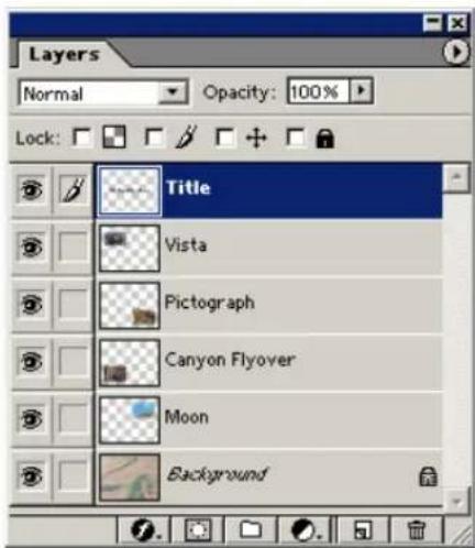
Your Avid editing application imports each layer as an individual matte key with alpha channel. In this example, the graphic uses a background image, so the system creates the background image as a master clip. (If the graphic uses a transparent background, the background layer is imported as a matte key.)
The following illustration shows the layers as they appear in a bin.
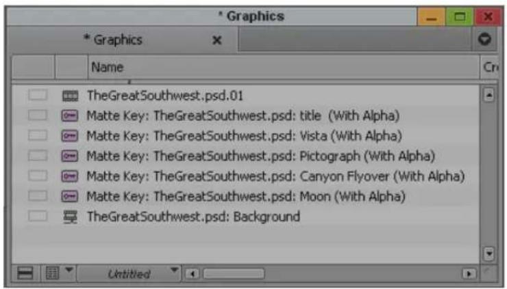
During the import, your Avid editing application creates a sequence with each layer on a separate video track. This makes it easy to edit all layers into the final sequence. This sequence preserves the names and order of the layers as created in the original Photoshop file.

You can then edit the tracks as necessary to build up to the full collage.
Support for Multilayered Photoshop Graphics Import
You should be aware of the following requirements for multilayered graphics import and details of how your Avid editing application handles the import:
• Graphics must be RGB 8 or 16 bits, or grayscale.
- Importing preserve layer order and layer names.
- Hidden layers are imported as matte keys.
- Importing converts Opacity to Foreground level in the Matte Key effect.
- Importing rasterizes text and shape layers.
- Not all layer options and types are supported for import.
For information on preserving layer effects during import, see “Importing Photoshop Files” on page 298.
For information on support for layer options and types, see the following tables.
Layer Option Supported Notes
| Blending Mode No To preserve the blending mode (Dissolve, Multiply, and so on), merge the layer into another layer that does not use a special blending mode. Only normal mode is supported. | ||
| Opacity Yes The imported layer's Level is set to the opacity specified in Photoshop. You can adjust opacity levels with the Foreground Level control in the Effect Editor. | ||
| Layer Group | Partial | Import ignores layer grouping and instead imports all layers, including grouped layers, as individual layers. To preserve a clipping group, merge the grouped layers into the base layer. |
| Layer Set Partial All layers within a set are imported as individual layers. | ||
| Layer/Set Mask No Import ignores layer and set masks. To preserve a layer mask, apply it to the layer. To preserve a set mask, merge the set into an empty layer. To preserve a special layer's mask, rasterize the layer. | ||
| Layer Style No Import ignores layer styles. To preserve a layer style, you must convert the style into layers. | ||
Special Layer Option Supported Notes
| Type Layer | Yes | — |
| Solid Layer | Yes | Solid layers import as a graphic with a full-screen opaque alpha channel. |
| Gradient Layer | Yes | Gradient transparency is preserved. |
| Pattern Layer | Yes | — |
| Adjustment Layer | No | Adjustment layers include Levels, Curves, Color Balance, Brightness/Contrast, Hue/Saturation, Channel Mixer, Gradient Map, Invert, Threshold, and Posterize. |
Importing Photoshop Files
To import a single-layer graphic, or a flattened multilayered Photoshop graphic:
▶ Follow the standard instructions for importing a graphic, as described in “Importing Media Files” on page 285.
To import a multilayered Photoshop file:
- Prepare the Photoshop graphic for import.
For more information, see “Support for Multilayered Photoshop Graphics Import” on page 297.
- Follow the standard instructions for importing a graphic, as described in “Importing Media Files” on page 285. To create the matte correctly, you need to click the Options button and select Alpha: Invert Existing.
- After you select one or more files and click Open, a message box opens.
- In the message box, do one of the following:
Click Sequence of Layers if you want to preserve all layers. If the number of layers exceeds the number of tracks supported, your Avid editing application creates a sequence that contains the number of tracks supported. Additional layers are imported into the bin, but not as tracks in a sequence. This selection applies to all files you select for import.
Click Flattened Image if you want to import the graphic as a single matte key or clip. Your Avid editing application flattens the file by combining the layers. This selection applies to all files you selected for import.
Hidden layers are not combined in the flattened image. Make sure all layers you want in the final image are visible. In addition, layers with partial transparency do not display properly in the flattened, imported image.
Click Select Layers if you want to select which layers to preserve.
The Select Layers dialog box opens. Select the layers you want to import and click OK. If you select more than 24 layers, your Avid editing application imports the additional layers but does not include them in the sequence.
Your Avid editing application displays messages as it creates media for each layer. At the end of the process, the selected bin displays the objects.
To preserve layer effects:
- For the first import, click Select Layers and select all layers except the layers that contain layer effects.
- For the second import, open Photoshop, hide the layers you've already imported, and show the layers that contain layer effects. During the import, click Flattened Image.
The resulting image contains only the layers that contain layer effects.
Digital Bars and Tone
If you expect to output your final sequence as a digital cut that requires calibration before playback (a digital cut that will be broadcast, for example), in most cases you might need a clip of color bars. You can add the clip to the front of the sequence, or you can output the clip separately as an assemble or insert edit onto tape during digital cut.
There are several ways to acquire a clip of bars, each with different advantages:
Acquisition Method Description
| Record bars and tone from a house generator | Requires the least effort with good results because you record high-quality bars and tone simultaneously, with a minimum of calibration. |
| Record bars and tone from a videotape | Lets you record bars and tone simultaneously, but you must calibrate carefully to ensure accuracy. In addition, the final clip reflects the quality of the source tape recording. |
| Record bars from an external color bar generator | Provides good results, but you must have a color bar generator, and you must rearrange your system inputs to attach the generator. In addition, you must acquire tone separately and sync it with bars within your Avid editing application. |
| Import a file of bars | Provides the highest quality results because the source image is already digital. If the file is accurate, the quality of the clip is ensured. You must, however, acquire tone separately and sync it with bars within your Avid editing application. For more information, see “Importing Color Bars and Other Test Patterns” on page 300. |
Importing Color Bars and Other Test Patterns
Avid editing applications supply files for color bars and other test patterns. You can import 8-bit PICT files or 16-bit TIFF files.
To import a test pattern from a file:
- Open an existing bin, or create a new one for the test pattern.
- Select the destination bin.
- Select File > Import.
The Select Files to Import dialog box opens.
- Do one of the following:
- (Windows) Click the Files of Type menu, and select Graphic Files.
- (Macintosh) Click the Show menu, and select Graphic Documents.
- Use the Look in menu (Windows) or the From menu (Macintosh) to locate the folder containing the test pattern file.
Test pattern files are located in the following folder:
- (Windows) drive:\Program Files\Avid\Avid editing application \SupportingFiles\Test_Patterns
-
(Macintosh) Macintosh HD/Applications/Avid editing application/SupportingFiles/Test_Patterns
-
Select a test pattern file from the File browser (Windows) or Source File list (Macintosh) for importing:
- 8-bit PICT files are located at the top level of the Test_Patterns folder.
- 16-bit TIFF files are located in the HD_720p, HD_1080i, SD_NTSC, and SD_PAL folders.
The file name appears in the File Name text box (Windows) or the Go to text box (Macintosh).
- Click Options to adjust the Import settings.
The Import Settings dialog box opens.
- Click the Image tab, and select the following options:
a. Select 601/709, non-square from the Aspect Ratio, Pixel Aspect area.
b. Select 601/709 from the Color Levels area.
c. Click OK to save the settings and close the dialog box.
- Click Open.
The clip for the imported file appears in the selected bin.
When you import SMPTE_Bars.pct, the file does not exactly match the SMPTE bars generated by the Video Output tool. The I and Q blocks in the bottom portion of the pattern cannot be exactly represented in the RGB color space used when importing files.
- If you must have I and Q blocks correct in a sequence, do one of the following:
▶Record SMPTE bars from a signal generator.
▶ Use the Video Output tool to generate SMPTE bars, and record them to tape using the controls on the deck. Then, capture them back into the system from the tape.
-
Load the new color bars clip into the Source monitor, and create a subclip of appropriate length for use in sequences (1 minute is a common standard).
-
Select the new subclip, Ctrl+click (Windows) or Command+click (Macintosh) the audio clip containing the tone, and select Bin > AutoSync.
A new subclip containing bars and tone appears in the bin.
- Rename the clip as necessary.
Importing Editcam Files
You can import clips recorded with Ikegami ^® disk-based Editcam ^™ or Editcam-station products. The Editcam is a digital news-gathering (DNG) camera that uses Avid's CamCutter ^® technology.
For more information about Editcam, CamCutter technology, and how these systems operate with nonlinear editors, see the Web site www.nltek.com.
Note the following restrictions:
- The CamCutter clips are not copied onto a media drive. The bin references clips physically located on the FieldPak. If you remove the FieldPak, the referenced clips appear as Media Offline.
-
The FieldPak has limited performance and is used only to record and play back clips. If you require multiple streams of video for advanced effects, the data might not be supplied fast enough for proper operation. If this situation occurs, you can do one of the following:
-
Render the effects. See “Rendering Effects” in the Help.
- Consolidate the sequence to a valid media drive. See “Consolidating Media” on page 449.
- Import the CamCutter clips as OMFI files. This effectively copies the clips to a media drive. See “Import Settings” on page 1414.
To import Editcam files:
- (Option) Select File > Mount All.
If you previously mounted the drive or volume, or if you inserted the FieldPak ^® before starting your Avid editing application, you do not need to perform this step.
- Open a bin.
- Select File > Import.
A dialog box opens.
- Click the Files of Type menu (Windows) or the Show menu (Macintosh), select CamCutter, and then select the CamCutter bin by doing the following:
a. From the desktop, select the FieldPak drive letter (Windows) or FieldPak volume name (Macintosh).
b. Open the bin folder on the FieldPak.
c. Select the CamCutter bins or select the .spl files you want to import.
The Outakes.bin contains clips that were discarded by the Editcam operator. These clips are generally not imported.
- Ignore the field specifying video resolution to import.
- Ignore the field regarding video and audio drive selection.
- Proceed with the import operation.
A dialog box opens, asking you to identify the drives that contain the media files.
- Select the FieldPak drive letters (Windows) or volume names (Macintosh) as appropriate.
If the drive or volume is not listed, go back to step 1 and retry the procedure.
- Complete the import process.
Your Avid editing application creates entries in the selected bin that reference the clips on the FieldPak.
For more information on importing files, see “Importing Media Files” on page 285.
Setting XDCAM Import Options
Set the default options to import XDCAM media in the XDCAM tab of the Import Settings dialog box.

Use these settings to override the selections made in the Select Files to Import dialog box or to set default behavior when you import XDCAM media. For more information, see “Import Settings: XDCAM Tab” on page 1419.
Importing XDCAM Media
XDCAM and XDCAM HD devices store media as MXF OP1a interleaved files. Your Avid editing application does not use these files directly. Instead, you must first import the media. The import process creates new video and audio MXF OP Atom media files which consist of one video track and up to eight audio tracks.

Low-resolution proxy media have the same number of audio tracks as the high-resolution formats.
There are several ways to access XDCAM media:
- Automatically import all proxy media when you load a disc in your XDCAM device. See “Automatically Importing Proxy Media from an XDCAM Device” on page 307.
- Manually import all proxy media on all discs currently loaded on your system. See “Importing Proxy Media from an XDCAM Disk” on page 309.
- Copy the proxy media files to a separate location (for example, to a folder copied on an FTP site), transfer them to a local drive or removable disk, and import the proxy media without directly accessing the XDCAM device. See “Copying XDCAM Proxy Media to a Local Drive or a Server” on page 310.
- Import proxy media, high-resolution media, or both using the Import function. See “Manually Importing XDCAM Media from the XDCAM Disk” on page 310.
For some workflows, you might want to import the proxy media first so you can start editing. Once you create your sequence, use the batch import function to import only those portions of the high-resolution clips needed for your sequence.
For other workflows, you might want to import the proxy media to an editing workstation, and then separately import the high-resolution media either to another workstation or to an Avid shared storage server using Avid Interplay Transfer. Your Avid editing application maintains the connection between the proxy media and the high-resolution media, so you can relink the edited clips at any time to the high-resolution master clips in a shared storage environment.

When you relink proxy media to high-resolution media, do not select Specific Resolution as the Relink Method option. Instead, select either Highest Quality or Most Compressed.
The import process for XDCAM media differs from the standard import in that you can import XDCAM media only at the native resolution of the XDCAM media (for information on XDCAM resolutions, see “Using XDCAM and XDCAM EX and XDCAM SR AMA Plug-Ins” on page 398).
XDCAM cameras record proxy audio at a sample rate of 8 kHz. When you import proxy media, you can choose to change (upconvert) the sample rate to your project rate. This might slow the import process a bit, but it greatly improves playback of audio tracks.
Importing XDCAM EX Media
XDCAM EX devices store media as MP4 interleaved files. Your Avid editing application does not directly support these files. You must first convert them to MXF OP1a files using the Sony XDCAM EX Clip Browser application, then you can import them in the same manner as XDCAM and XDCAM HD clips.
First you need to export the clip from the XDCAM EX device. There are two export options to choose from, one option is to export “MXF for NLEs.” This option creates an OP1a .mxf file, and then import the file into a bin. The other option is to choose to export “Avid AAF.” This option creates an AAF composition file, and concurrently creates an OPAtom MXF media file. In the Avid AAF export options, choose a valid Avid MediaFiles folder. The AAF composition file links to the media once you import.
To import an XDCAM EX clip using Avid AAF:
- With an XDCAM EX camera or reader attached to your system, insert an XDCAM EX card.
- Launch the Sony XDCAM EX Clip Browser.

The Sony XDCAM EX Clip Browser application ships with your Sony camera or reader. For information about the Sony XDCAM EX Clip Browser, see Sony's documentation.
- From within the Clip Browser, choose Tools > User Configuration, and click the Conversion tab.
- In the Avid AAF section, click Browse and select the folder where you want to place the AAF composition file.
- In the User Configuration window, click the General tab.
-
In the Copy section, click Browse and select a valid Avid MediaFiles folder destination. This folder holds the OPAtom files and the Avid editor recognizes this media after you import the AAF composition.
-
Click OK.
- In the Clip Browser, click or Ctrl+click (Windows) or Command+click (Macintosh) the XDCAM EX clips you want to export.
-
Right-click the clip and select Export > Avid AAF. The clips appear in the folder location you selected.
-
Open the Avid editor.
- Open a project and a bin, or create a new bin.
-
With the bin selected, right-click and select Import.
The Select files to Import dialog box opens. -
Locate and select the AAF composition files, and then click Open. All metadata information is embedded with the clip. The video resolution in the Import window is ignored.
The XDCAM EX clips appear in the bin.
To import an XDCAM EX clip using MXF for NLEs:
- With an XDCAM EX camera or reader attached to your system, insert an XDCAM EX card.
- Launch the Sony XDCAM EX Clip Browser.

The XDCAM EX Clip Browser application should have come with your Sony camera or reader. For information about the Sony XDCAM EX Clip Browser, see Sony's documentation.
- From within the Clip Browser window, select the clips you want to export.
- Right-click the clips and select Export > MXF for NLEs.
This creates OP1a MXF media files that you import into the Avid editor. - The MXF for NLEs window opens, click the Browse button and select the destination folder for the MXF media files.
- Click Execute.
- Open the Avid editor.
- Open a project and a bin, or create a new bin.
-
With the bin selected, right-click and select Import.
The Select files to Import dialog box opens. -
Locate and select the MXF media files, and then click Open.
All metadata information is embedded with the clip. The video resolution in the Import window is ignored.
The XDCAM EX clips appear in the bin.
Automatically Importing Proxy Media from an XDCAM Device
You can use this method to automate the process of importing proxy media from your XDCAM device to your Avid editing application.
To import proxy media from an XDCAM device:
- Double-click Import in the Settings list.
The Import Settings dialog box opens.

- Click the XDCAM tab.
- Select Automatically Import Proxies when disk is inserted.
- Click OK.
- Open the bin in which you want to store the imported files.
If you do not select a bin, or if you have more than one bin open, a dialog box opens and directs you to select from a list of open bins or create a new bin.
- Insert a disk into your XDCAM device.
The Import XDCAM Proxy from drive: dialog box opens.
- Type a name in the Disk Label text box.
Your Avid editing application uses the disk label for operations such as Batch Import, where you are prompted to insert a specific XDCAM disc that holds the files you want to import. A disk label is required in order to import XDCAM media.
- Click the Single/Dual Drives button, and select a destination drive for the imported file from the menu.
- Click Import.

When the import finishes, the clips appear in the selected bin.
Your Avid editing application imports XDCAM media at the native resolution of the media on the XDCAM disc. Your Avid editing application ignores other resolution settings — for example, in the Select Files to Import dialog box.
- (Option) Repeat this procedure for each XDCAM disc that holds media you want to import.
Importing Proxy Media from an XDCAM Disk
You can use this method when you want to import proxy media stored on your disk, but you have not opted to import the proxy media automatically. If you want to import only some of the files on your disk, use the procedure described in “Manually Importing XDCAM Media from the XDCAM Disk” on page 310.

For information on setting the XDCAM import to start automatically, see “Automatically Importing Proxy Media from an XDCAM Device” on page 307.
To import proxy media from a disk:
- Open the bin where you want to store the imported files, and select it to make it the active bin.
- Insert a disk into your XDCAM device.
- Select File > Import XDCAM Proxy.
The Import XDCAM Proxy from drive: dialog box opens.
- Type a name in the Disk Label text box.
Your Avid editing application uses the disk label for operations such as Batch Import, where you are prompted to insert a specific XDCAM disc that holds the files you want to import. A disk label is required in order to import XDCAM media.
- Click the Single/Dual Drives button, and select a destination drive for the imported file from the menu.
- Click Import.
When the import finishes, the clips appear in the selected bin.
Your Avid editing application imports XDCAM media at the native resolution of the media on the XDCAM disc. Your Avid editing application ignores other resolution settings — for example, in the Select Files to Import dialog box.
- (Option) Repeat this procedure for each XDCAM disc that holds media you want to import.

Copying XDCAM Proxy Media to a Local Drive or a Server
You might want to import proxy media when the XDCAM device is not available. For example, if you want an editor to start editing the XDCAM footage while the actual XDCAM disk is at another location, you can transfer the proxy media files to an FTP server. You can then download the files from the server, and an editor can import the proxy media and begin editing. Later, you can relink the proxy media to the high-resolution media, or use the batch import function to import the high-resolution media for final editing and finishing.
When you copy the XDCAM media files from the XDCAM device to another system or to a removable drive, you need to copy only the Sub folder (for proxy media) or the Clip folder (for high-resolution media).
A possible workflow to import XDCAM proxy media from a non-XDCAM drive uses the following steps:
- Copy the proxy folder (Sub) from an XDCAM device to an FTP server.
- Download the files to a local drive.
- Import the proxy media to an Avid editing application from a local drive just as you would from an XDCAM disc, and then begin editing.
See “Manually Importing XDCAM Media from the XDCAM Disk” on page 310.
- When the XDCAM disk is available, either import or batch import the high-resolution media to finish editing.
See “Importing Media Files” on page 285 or “Batch Importing High-Resolution XDCAM Media from the XDCAM Disk” on page 313.
Manually Importing XDCAM Media from the XDCAM Disk
Use the standard Import function to import XDCAM media into your Avid editing application. Set the default XDCAM import options in the XDCAM tab of the Import Settings dialog box. For more information on import options, see “Import Settings: XDCAM Tab” on page 1419.
You can import files through the:
- Import function
- Drag and drop method of importing files
For more information, see “Importing Media Files” on page 285 and “Using the Drag-and-Drop Method to Import Files” on page 317.

Your Avid editing application imports XDCAM media at the native resolution of the media on the XDCAM disk. The system ignores other resolution settings — for example, in the Select Files to Import dialog box.
You can locate the MXF media files in the following directories on your XDCAM disk:
• High-resolution media — XDCAM drive:\Clip
- P r o x y m e d i a — XDCAM drive:\Sub
Importing Essence Marks as Markers in XDCAM Media
Essence Marks store metadata about media clips. You can set Essence Marks manually or automatically with the XDCAM cameras. Use Essence Marks to mark events such as clip start points or audio clipping and for sorting and searching clips stored on XDCAM discs. For a description of Essence Marks, see your Sony documentation.
You can import Essence Marks as markers when you import either proxy media or high-resolution media. The markers appear in the bin of the XDCAM master clips, and you can view them in the Source/Record monitor, in the Timeline, and in the Markers window. For information on using marker information as you edit, see “Suggested Uses for Markers” on page 523.
To import Essence Marks as markers:
- Double-click Import in the Settings list.
The Import Settings dialog box opens.

- Click the XDCAM tab.
- Select Import Essence Marks as markers.
- Click OK.
Editing XDCAM Proxy Media
When you import proxy media files, a new master clip is created that you can edit in the timeline just like any other clip. You can mix the clips in the Timeline with any supported resolutions, add effects or titles, or perform any other editing function available in your Avid editing application.
XDCAM proxy media is single-frame resolution media. For the best performance during playback, select Draft Quality or Best Performance from the Video Quality Menu in the Timeline. For more information, see “Video Quality Options for Playback” on page 516.
To set the playback options for XDCAM media:

- Right-click the Video Quality menu button, and select Draft Quality (yellow/green) or Best Performance (yellow/yellow).
Some effects, such as IllusionFX and FluidMotion effects, do not playback in real time when you select Draft Quality. For these effects, you must also select the Progressive Source button in the Effect Editor before you render.
- (Option) You can perform emergency play-to-air operations of the proxy media as an export, as a Send to Playback operation, or as a digital cut.
Batch Importing High-Resolution XDCAM Media from the XDCAM Disk
Once you finish editing your sequence with proxy media, you can replace the low-resolution media with the corresponding high-resolution media with the Batch Import command. The Batch Import command lets you reimport the high-resolution DVCAM, MPEG IMX, or XDCAM HD files, directly from the XDCAM disk, while automatically linking the new imported material with the sequences and master clips created with the low-resolution MPEG-4 media. If you batch import media for an edited sequence, the import operation copies only those portions of the high-resolution master clip needed by the sequence, not the whole clip. If you batch import master clips, the import process copies the entire clip.

The Disk Label column in the bin headings displays the XDCAM disk labels created when you import the XDCAM media. For information on displaying bin columns, see “Bin Column Headings” on page 352. If necessary, you can use the Modify command to change the name in the Disk Label column.
You can also import the high-resolution media files separately. Since importing high-resolution master clips requires more storage, time, and bandwidth than batch importing only the necessary parts of clips, you might want to import the master clips to another workstation or to another system in a shared storage environment — for example, to an Avid shared storage server. Once you import the high-resolution media, you can Relink to move between the proxy media and the high-resolution media. For more information about relinking media, see “Editing and Finishing High-Resolution XDCAM Media” on page 316 and “Relinking Media Files” on page 467.
To batch import high-resolution XDCAM media:
- Double-click Import in the Settings list.
The Import Settings dialog box opens.
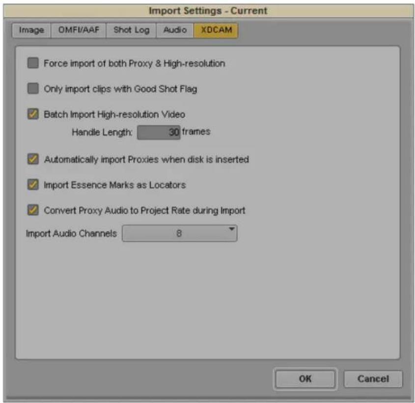
- Click the XDCAM tab.
- Select Batch Import High-resolution Video.
- Click the Handle Length text box and type the number of additional frames you want to import at the heads and tails of the new master clips.
This provides enough overlap for trimming and adding transition effects. The default is 30 frames.
- Click OK.
- Open the bin, and select the sequences or master clips created with proxy media that you want to replace with high-resolution media.
- Insert a disk into your XDCAM device.
- (Option) If your source media is stored on multiple XDCAM discs, and you have multiple XDCAM devices, you can insert all the discs at the same time.
- Select Clip > Batch Import.
A message box opens.
- Click the All Clips button.
The Batch Import dialog box opens.

Single/Dual Drives button (left) and Video Drive and Audio Drive menu location (right) in the Batch Import dialog box
Your Avid editing application imports XDCAM media using the native resolution of the XDCAM files.
- Click the Video Drive and Audio Drive menus, and select a destination drive or drives for all the media files.
You can separate video and audio onto different drives.
- Click Import.
The high-resolution files import. If the source media is stored on more than one disk and not all disks are attached to your system, the system prompts you to insert additional disks as needed.
Editing and Finishing High-Resolution XDCAM Media
Once you import the high-resolution media, you can playback and edit your sequence with full resolution and in real-time. You can also send the sequence to a broadcast playback server using Avid Interplay Transfer.
As you edit your sequence, you can move between the proxy media and the high-resolution media by relinking your clips with the corresponding media files. When you relink proxy media to the high-resolution media, select one of the following Relink Method options:
- Highest Quality
- Most Compressed

Do not select Specific Resolution as the Relink Method.
This allows the audio tracks to relink to the appropriate audio files. For more information about the Relink command, see “Relinking Media Files” on page 467.
Importing P2 Clips and Media
P2 media files include information (metadata) that lets them appear as master clips in an Avid editing application. You can import the P2 clips directly from a P2 card or a copy of a P2 card on another drive into a bin. You can also import the media associated with the clips if you want to reuse the P2 card, for example, if you want to capture additional material onto the card in a camera. For more information about copying P2 cards to another drive, see “Copying File-Based Media to a FireWire or Network Drive” on page 380.
To import P2 clips directly from a P2 card or a copy of a P2 card on a drive:
- Open and select the bin where you want to import the master clips to.
- Select File > Import P2 > Clips to Bin.
The Browse for Folder dialog box opens.
- Navigate to the P2 files:
▶ Navigate to the P2 card
▶ Navigate to the folder where multiple P2 cards reside. The system can import P2 files from multiple cards as long as each card has a Contents folder.
The Import P2 option imports all the clips on the card.
- Click OK.
A progress box appears as the clips import. When the import is complete, the clips appear in the active bin. You can play and edit the clips; the media resides on the P2 card. If you leave your Avid editing application and then restart it, you see the clips in the bin, but the media is offline. You need to import the clips again to continue working with them.
To import media from a P2 card:
- Open and select the bin where you want to import the clips to.
- Select the master clips, sequences, or a combination which you want to import media.
- Select File > Import P2 > Media.
- Follow steps 3 and 4 in the preceding procedure.
The system consolidates the items selected according to the current settings in the Media Creation Import tab.
Importing Sequences from Pro Tools through Interplay
You can import a sequence you have worked on in Pro Tools back into your Avid editing application. You need to have checked the sequence into Interplay from Pro Tools.
To import a sequence from Pro Tools:
- Open the Interplay Window and navigate to the location of the checked-in sequence.
- Click the sequence and drag it into your bin.
Your Avid editing application checks out the sequence and imports the sequence and the related files into the bin. For more information, see “Using Pro Tools and Interplay” in Avid Interplay Best Practices.
Using the Drag-and-Drop Method to Import Files
To import one or more files by using the drag-and-drop method:
- Click the Settings tab in the Project window.
The Settings list appears. - Click Import.
- Select either the default Import setting or one you have created.
To view or modify the parameters, double-click the setting. For more information, see “Creating and Modifying Import Settings” on page 282. -
Open the bin in which you want to store the imported files.
-
Open the folder that contains the files you want to import.
- Select the file you want to import and drag it to the bin. To select multiple files, Ctrl+click (Windows) or Command+click (Macintosh) the files and drag them to the bin.
- (XDCAM only) The Import file(s) from XDCAM dialog box opens. Type a name in the Disk Label text box, and then click Import.
Your Avid editing application uses the disk label for operations such as Batch Import, where it prompts you to insert a specific XDCAM disc that holds the files you want to import. A disk label is required in order to import XDCAM media.
Reimporting Files
If you are working with master clips or sequences that contain imported material, you can use the Batch Import command to reimport the imported files. For example, you might want to do the following:
- Upgrade the video resolution of the imported files to an online resolution for distribution.
- Create new media files when the media files are lost or accidentally deleted.

Reimporting requires your original source file. Do not delete the media files for imported files unless you have access to the source files.
The Batch Import command lets you reimport files while automatically linking the new imported material to the original master clips and sequences. When you play your sequence after reimporting the files, the new imported material plays in your sequence.
When you reimport a media file, the entire media file, including all tracks, is reimported. For example, if you imported only the video track of a file that contains both video and audio and edited it into a sequence, the reimport process imports both the video and audio from the source file.
You cannot reimport a mixed-rate sequence because you cannot batch import material in formats other than the project format. A message box appears if you attempt to reimport such material. Instead, you can decompose the sequence, then reimport the resulting clips by opening the bin in projects that match each of the decomposed formats.

OMFI files can contain only one master clip when you reimport them.
To reimport files:
- (Option) Mount any removable media drives that held the original media.
- Do one of the following:
▶Double-click Media Creation in the Settings list.
▶Select Tools > Media Creation.
The Media Creation dialog box opens.
-
Click the Media Type tab.
-
Click the File Format menu, and select the format (MXF or OMF).

If your project uses an HD resolution, you cannot select OMF as a file format. MXF is selected by default.
-
Open the bin, and select the imported master clips and sequences you want to reimport.
-
Select Clip > Batch Import.
A message box opens.

- Click one of the following:
Option Description
Offline only Reimports only the selected imported master clips that are missing their media files.
All clips Reimports all the selected imported master clips. For example, click this button if you need to change the video resolution of the imported master clips.
The message box closes and the Batch Import dialog box opens. For reference information on the Batch Import dialog box, see “Batch Import Dialog Box” on page 320.
- If you want to remove clips from the list, select the clips you want to remove and then click Skip This Clip.
The clips are removed from the list and are not imported.
- Locate the sources for files that weren't found by doing the following:
a. Select a clip or clips displayed in red in the Selected Clips section.
b. Click the Set File Location button.
The Locate File dialog box opens.
c. Navigate to the location of the source file.
If you select more than one clip displayed in red, the system first attempts to find the rest of the clips in the same folder as the first clip and then in folders that maintain the same relationship with the first clip's folder.
Found clips are displayed in black.
- Click the Video Resolution menu, and select a video resolution for all the reimported files.

OMFI and AAF files do not convert DV 25 to DV 50 or DV 50 to DV 25.
- Click the Video Drive and Audio Drive menus, and select a destination drive or drives for all the media files.
You can separate video and audio onto different drives by clicking the Single/Dual Drives button.
- (Option) By default, your Avid editing application imports the file using the Import settings from the last time it imported the file. You can change the Import settings for all clips to import by doing the following:
a. In the Import Options section, select "Override clip settings with current settings."
b. Click Current Settings to open the Import Settings dialog box.
c. Select the appropriate options.
d. Click OK to close the Import Settings dialog box.
- Click Import.
The file is imported.
Batch Import Dialog Box
The Batch Import dialog box lets you select a source file for each master clip that you selected in a bin. Your Avid editing application finds the source file automatically if the it is located in the same folder where you last imported the file.
For information on working in the Batch Import dialog box as part of the reimporting process, see “Reimporting Files” on page 318.
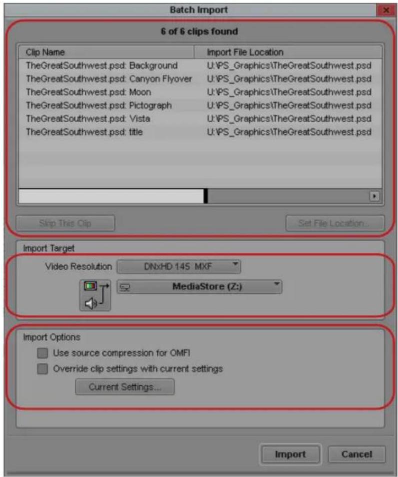
Batch Import dialog box. Top: Selected Clips area. Center: Import Target area (including, top to bottom, Video Resolution menu, Video Drive menu, and Audio Drive menu). Bottom: Import Options area.
Area Control Description
Selected Clips list Shows the clips you selected for import. The caption at
the top of the section summarizes the total number of clips shown and how many of them are available for import.
Found clips display in black.
Clips not found in their original location display in red.
Skip This Clip button Removes any clips that you select in the list so that they are not reimported.
Area Control Description
| Set File Location button Lets you locate sources for files whose sources are not found automatically (displayed in red in the list). | |
| Import Target Lets you select a resolution and destination drives. | |
| Video Resolution menu Lets you select a video resolution. | |
| Video Drive and Audio Drive menu Let you select a destination drive for the media files. | |
| Import Options Contains global settings that affect all the files you are importing. | |
| If you change the Import settings by using the Import Options section, the new settings apply to all the files you import. | |
| Use Source Compression for OMFI | When selected, your Avid editing application takes the resolution used to create the OMFI files (the native resolution) to reimport the files if the resolution is available in your Avid editing application. This allows for fast import of these files.When deselected, or if a resolution is not available on the system, your Avid editing application uses the resolution in the Video Resolution menu as the resolution for import. This option always overrides the OMFI Resolution setting in the Import Settings dialog box. |
| Override clip settings with current settings | Lets you change the Import settings for all imported files. By default, each file imports using the Import settings from the last time it was imported. |
| Current Settings button | Opens the Import Settings dialog box, allowing you to change the current import options. |
9 Working with Bins
Bins provide powerful database tools for organizing and managing your captured material. Bin functionality lets you view bin objects and information in several different ways. You can rename, sort, sift, duplicate, assign colors, and delete clips and sequences, move or copy clips from one bin to another, and print single-clip frames or whole bins.
The following topics provide information on working with bins:
- Object Icons in Bins
- Bin Views
- Bin Procedures
• Working with Bin Columns - Modifying Clip Information
- Working with Film Information in Bins
- Creating a Storyboard
- Setting the Bin Display
• Film Scene Workflow
• Sifting Clips and Sequences
• Working with Restricted Material - Printing Bins
• Working with Export Volumes
Object Icons in Bins
Bins use icons to identify clips, sequences, and other media objects that they display. The table describes all of the object icons that you might see in a bin display.

By default, bins display all existing media objects except source clips and rendered effects.
Icon Object Type Description
| Master Clips A clip that references audio and video media files formed from captured footage or imported files | ||
| Stereo Master Clips | A single clip generated from a left and right eye pair of master clips that were created when stereoscopic full frame material was captured or imported. | |
| Shared Storage Master Clip | A master clip that references media files located on a shared storage systemIn an Avid Interplay MultiRez environment, the icon displayed for a clip might change, depending on whether the clip is linked to shared storage or local storage.The Dynamic Relink settings determine how the clip is currently linked. | |
| MultiRez Shared Storage Master Clip | In a MultiRez environment, clip media is partially available in current resolution. | |
| Remote clip | In an Interplay Sphere environment, a clip checked out of Interplay by a remote system appears with an arrow pointing down. The clip in the bin uses a proxy resolution. | |
| Remote Sequence | In an Interplay Sphere environment, a local sequence that has been uploaded to or synced with a remote Interplay database appears as a sequence icon with an arrow pointing up. | |
| In-progress Master Clips | A master clip that references media currently being captured that you can view and edit. For more information, see “Understanding Frame Chase Capture” on page 236. | |
| Subclips A clip that references a selected portion of a master clip | ||
| Shared Storage Subclips | A subclip that references media files on a shared storage system | |
| Audio Clips A clip that references audio media files formed from captured audio or imported files | ||
| Shared Storage Audio Clips | An audio clip that references media files located on a shared storage system | |
| In-progress Audio Clips | An audio clip that references media currently being captured that you can play and edit. For more information, see “Understanding Frame Chase Capture” on page 236. | |
| Sequences A clip that represents an edited program, partial or complete, that you create from other clips | ||
| Sources A clip that references the original videotape source footage for master clips | ||
| AMA linked video clip | Indicates a file based video clip that links directly into a bin through an AMA plug-in. | |
| 48 | AMA linked audio clip | Indicates a file based audio clip that links directly into a bin through an AMA plug-in. |
| Effects A clip that references an unrendered effect that you create. | ||
| Motion Effects A file in the bin that references effect media files generated when you create motion effects | ||
| Rendered Effects | A clip that references an effect media file generated when you render an effect | |
| Groups (For MultiCamera editing) Clips containing two or more grouped clips, strung together sequentially according to common timecodes | ||
Bin Views
You can display the contents of your bins in three different ways using the Bin View buttons at the bottom of the bin window.
Using Text View
Text view provides the most complete view of clip information. It uses database columns that you can rearrange and customize to suit your needs.
You can select individual or multiple headings to display or hide in the bin. For a complete description of each column heading, see “Working with Bin Columns” on page 345.
To enter Text view:
▶Click the Text View button in the bin.

Text view in the bin. Top to bottom: bin column headings, Bin View button, Bin View menu
To select column headings:
- With a bin in Text view, do one of the following:
▶Select Bin > Choose Column.
▶Right-click and select Choose Column.
The Bin Column Selection dialog box opens.
- Select the headings you want to add to the bin:
▶Click the name of a heading to select it.
▶Click a selected heading to deselect it.
▶Click All/None to select or deselect all the headings.
- Click OK.
Only the headings selected in the Bin Column Selection dialog box appear in the bin or bin view.
For information on hiding columns, see “Moving, Aligning, and Deleting Bin Columns” on page 346.
Sorting in Bins
You can sort clips to arrange them in either numerical or alphabetical order, based on the data in the column you select as the sorting criteria. When you sort clips, any selected items in the bin remain active.
You can also sort clips by color if you have assigned colors to the clips. For more information, see “Assigning Colors to Objects in a Bin” on page 341.
If you want to sort clips in a customized order in Text view, you must first rearrange the clips in Script view, and then return to Text view. For information about Script view, see “Duplicating, Copying, and Moving Clips and Sequences” on page 336.
Sorting Clips and Sequences
You can automatically sort clips and sequences in Text view. If you need to view sorted clips in Script or Frame view, sort them in Text view first and then return to Script or Frame view.
To sort clips in ascending or descending order:
- With a bin in Text view, do one of the following:
▶ Double-click the heading of the column that you want to use as the criterion.
▶Right-click the column heading and select Sort on Column, Ascending or Sort on Column, Descending.
If the Sort command appears dimmed in the menu, you have not selected a column.
- To reverse the order of the sort, do one of the following:
▶Double-click the column heading again.
Right-click the column heading and select the reverse order for the Sort on Column command.
To reapply the last sort, do one of the following:
▶Select Bin > Sort Again with no column selected.
This step is useful after you add new clips to a sorted bin.
▶Click the column heading and select Bin > Sort.
To perform a multilevel sort using the information in the bins:
- With a bin in Text view, arrange the columns in the bin to establish the primary column.
The column that appears farthest to the left in the bin has higher sort priority. - Select the headings for the columns you want to contribute to the sort criterion. Cmd+click (Macintosh) or Ctrl+click (Windows) columns to add them to your selection. You can also Shift+click headings to select a range of columns.
- Select Bin > Sort.
The objects in the bin sort.
To sort clips by color:
- Click the Color column heading in the bin.
- Do one of the following:
▶Double-click the column heading.
▶Select Bin > Sort.
The objects in the bin sort by color. Colors sort by hue, saturation, and value.
Understanding Bin Views
Use the Bin View menu (Text view only) to select different bin views. The Bin View menu appears to the right of the bin tabs. The following table describes the default bin views that are available.
View Description
Capture Contains a set of headings that are useful when capturing footage from tape — for example, start and end timecodes, tape, tracks, and resolutions.
Custom Lets you create and save customized views. The Name heading is only required column heading, which displays by default. Add, hide, or rearrange column headings to customize the view.
Film The film-related column headings, including key number, ink number, and pullin display. If you work on a non-film-related project and select Film view, only the non-film-related columns display.
Format Displays the video formats, resolutions, and projects for the bin's contents
Media Tool Duplicates the headings currently saved in the Media tool.
Statistics Displays standard statistical column headings derived from information established during capture, such as start and end timecodes, duration, and resolution.
You can also create and save customized bin views, and then access them from the Bin View menu. For more information, see “Saving a Custom Bin View” on page 329.
When you create a new bin view, your Avid editing application saves the settings for the view so that you can alter, copy, or delete the settings at a later time. You can name and save bin views to suit your needs.
Bin view settings are also available in the Settings list of the Project window. For more information, see “Working with Settings” on page 1339.
| Name | Creation Date | Duration | Tracks | Dance | Format |
| ■ Globe room 2-new.01 | 4/26/2006 18:22:46 | 3:06 | VL | workspace2 (K) | SD 24p NTSC |
| ■ Globe room 2-new.01 | 4/26/2006 18:30:17 | 3:06 | VL | workspace2 (K) | SD 24p NTSC |
| ■ Mediel new.01 | 4/26/2006 18:22:40 | 3:07 | VL | workspace2 (K) | SD 24p NTSC |
| ■ Harbour cruise.new.01 | 4/26/2006 18:22:42 | 3:07 | VL | workspace2 (K) | SD 24p NTSC |
| ■ Friends 2-new.01 | 4/26/2006 18:30:17 | 3:07 | VL | workspace2 (K) | SD 24p NTSC |
| ■ Harbour cruise.new.01 | 4/26/2006 18:30:17 | 3:07 | VL | workspace2 (K) | SD 24p NTSC |
| ■ Mumbai new.01 | 4/26/2006 18:30:17 | 3:07 | VL | workspace2 (K) | SD 24p NTSC |
| ■ Fountain run.new.01 | 4/26/2006 18:30:52 | 3:08 | VL | workspace2 (K) | SD 24p NTSC |
| ■ Fountain run.new.01 | 4/26/2006 18:30:17 | 3:08 | VL | workspace2 (K) | SD 24p NTSC |
| ■ Collo Man.new.01 | 4/26/2006 18:21:52 | 3:09 | VL | workspace2 (K) | SD 24p NTSC |
| ■ Beacon Hill.new.01 | 4/26/2006 18:32:19 | 3:09 | VL | workspace2 (K) | SD 24p NTSC |
| ■ Harbor PCV.new.01 | 4/26/2006 18:32:45 | 3:09 | VL | workspace2 (K) | SD 24p NTSC |
| ■ Bid trade Ol-new.01 | 4/26/2006 18:30:17 | 3:09 | VL | workspace2 (K) | SD 24p NTSC |
| ■ Harbor PCV.new.01 | 4/26/2006 18:30:17 | 3:09 | VL | workspace2 (K) | SD 24p NTSC |
| ■ Beacon Hill.new.01 | 4/26/2006 18:30:17 | 3:09 | VL | workspace2 (K) | SD 24p NTSC |
| ■ Collo Man.new.01 | 4/26/2006 18:30:17 | 3:09 | VL | workspace2 (K) | SD 24p NTSC |
| ■ Air bat hp.new.01 | 4/26/2006 18:32:35 | 3:10 | VL | workspace2 (K) | SD 24p NTSC |
| ■ Air bat hp_new.01 | 4/26/2006 18:30:17 | 3:10 | VL | workspace2 (K) | SD 24p NTSC |
| ■ Cligo sign.new.01 | 4/26/2006 18:31:59 | 3:13 | VL | workspace2 (K) | SD 24p NTSC |
| ■ Local new.01 | 4/26/2006 18:32:37 | 3:13 | VL | workspace2 (K) | SD 24p NTSC |
| ■ Cligo sign new.01 | 4/26/2006 18:30:17 | 3:13 | VL | workspace2 (K) | SD 24p NTSC |
| ■ Dance Silhouette new.01 | 4/26/2006 18:30:17 | 3:13 | VL | workspace2 (K) | SD 24p NTSC |
| ■ Local new.01 | 4/26/2006 18:30:17 | 3:13 | VL | workspace2 (K) | SD 24p NTSC |
| ■ Building precut new.01 | 4/26/2006 18:31:58 | 3:15 | VL | workspace2 (K) | SD 24p NTSC |
| ■ Building precut now.01 | 4/26/2006 18:30:17 | 3:15 | VL | workspace2 (K) | SD 24p NTSC |
| ■ Walk by new.01 | 4/26/2006 18:33:15 | 3:19 | VL | workspace2 (K) | SD 24p NTSC |
| ■ Walk by new.01 | 4/26/2006 18:30:17 | 3:19 | VL | workspace2 (K) | SD 24p NTSC |
| ■ Harbor precut new.01 | 4/26/2006 18:37:43 | 3:20 | VL |
Bin tabs (top), Fast Menu button (bottom left), and Bin View menu (bottom right) in the bin
Saving a Custom Bin View
To save a bin view:
- Open a bin, click the Text View button.
- Resize, add, hide, or rearrange bin columns according to preference to customize your view. The Name column is the default and the only required column heading.
The bin view name changes to an italic name with the file name extension .n to indicate that it no longer matches the original view. If you select a new bin view setting while the current setting is untitled or italic, the system discards the current setting.
- Click the Bin View menu, and select Save as.
The View Name dialog box opens.
- Type a name for the custom view, and click OK.
To change a custom bin view with the Bin View dialog box:
- Click the Settings tab in the Project window.
The Settings list appears.
- Double-click the custom bin view you want to change.
The Bin View dialog box opens.
- Select and deselect the columns you want to display.
4. Click OK.
Using Frame View
In Frame view, each clip is represented by a single frame, with the name of the clip displayed below the frame. The system uses the head frame as the default.
You can perform the following functions in Frame view:
- Enlarge and reduce the sizes of the frames.
You must enlarge or reduce all frames together, and you cannot change the sizes of individual frames.
- Rearrange the display of the frames in the bin by moving them.
- Realign the frames in a bin after you have changed their display.
- Select any frame to represent the footage.
- Play back the footage within any clip.
To enter Frame view:
▶Click the Frame View button in the bin.
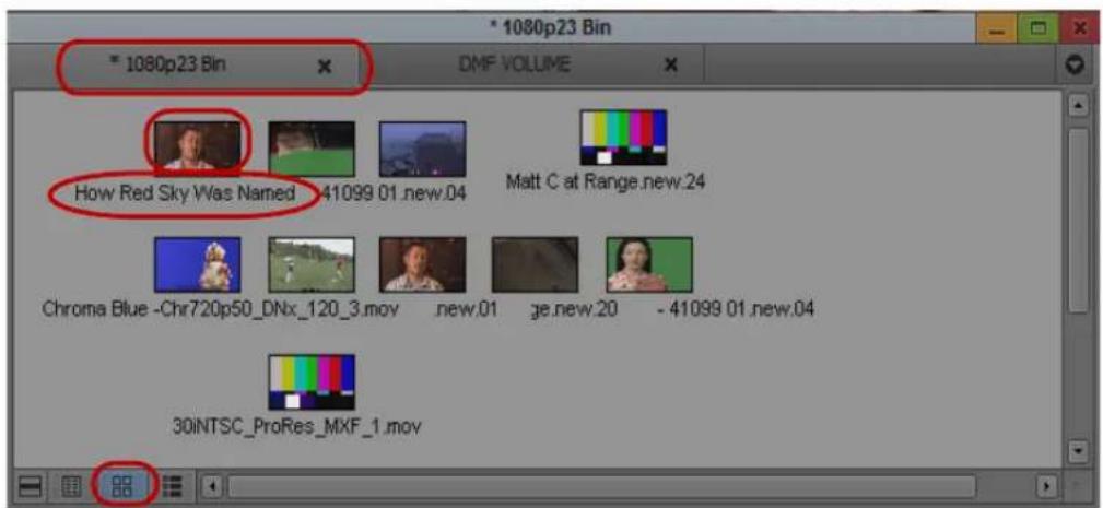
Frame view in the bin. Top to bottom: bin tab, clip frame, clip name, and Frame View button
To enlarge the frame size:
▶Select Edit >Enlarge Frame.
The display size increases each time you select this option, up to seven times.
To reduce the frame size:
▶Select Edit > Reduce Frame.
The display size decreases each time you select this option, up to seven times.
To rearrange a single frame:
- Click the frame, and drag it to its new position.
- Click the background area of the bin to deselect the clips.
To rearrange multiple frames:
- Do one of the following:
▶Shift+click the frames.
▶ Lasso the frames by clicking the mouse pointer outside the first frame and drag it to surround the frames with a white dotted line.
-
Drag the selected frames to a new position in the bin.
-
Click the background area of the bin to deselect the clips.
To align all frames to an invisible grid:
▶Select Bin > Align to Grid.
To align selected frames to an invisible grid:
▶Select Bin > Align Selected to Grid.
To space the frames evenly to fill the Bin window:
▶Select Bin > Fill Window.
To arrange frames in the order in which they are sorted in Text view:
▶Select Bin > Fill Sorted.
To change the frame identifying the clip:
- Select the clip that you want to change.
Press and hold the K key (Pause) on the keyboard and press the L key (Play Forward) to roll the footage within the frame forward at slow speed. To move backward through the footage, press and hold the K key and press the J key (Play Reverse).
- When you see the frame that you want to use, release the keys.
Your Avid editing application saves your choice as part of the bin configuration.

Use the Home key or End key to change the represented frame. On systems with Symphony options, use the Home key or End key on the keyboard or jog or shuttle with the mouse to change the represented frame. For more information about playing footage, see “Controlling Playback” on page 506.
If you have group or multigroup clips in the bin and want to change the displayed frame, use controls in Source/Record mode.
Using Script View
Script view combines the features of Text view with Frame view and adds space for typing notes or script. The frames are displayed vertically on the left side of your screen with the text box next to each clip. As in Text view, each clip is represented by a single frame, and the head frame is the default. Clip information is displayed above the text box.
You can do the following in Script view:
• A d d t e x t .
- Use basic word processing procedures to highlight, delete, cut, copy, and paste text between script boxes.
- Rearrange clips.
- Select any frame to represent the footage.
- Play back the footage within any clip.
To enter Script view:

▶Click the Script View button in the bin.
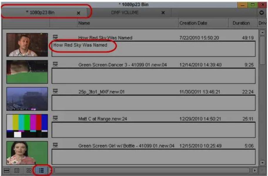
Script view in the bin. Top to bottom: bin tabs, script text box, Script Bin View button
To type text in the script box:
- Click the text box and begin typing.
- (Option) If the text you type extends beyond the size of the script box, you can use the Page Up and Page Down keys on the keyboard to scroll through the text.
This text does not appear in sequences edited from the clips, only in printouts of the bin in Script view.
To change the represented frame in Script view:
▶Press the J-K-L keys to move through the clip.
To rearrange clips in Script view:
▶Drag each clip up or down to a new location in the bin.
Sort and sift clips in Text view, and then return to Script view to display selected clips in the sort order you want.

When you return to Text view, the order of the clips is changed there as well.
Bin Procedures
You can manipulate material in the bin in a variety of ways, including selecting, deleting, duplicating, moving, copying, and sifting clips and sequences.
When you work with bins, an asterisk appears before the bin name in the bin's title bar. The asterisk indicates that the changes to the bin have not been saved. Once you save the bin, the asterisk is removed.

Using Bin Tabs
When you create a new bin, the bin opens in a separate window by default. However, you can drag bins to a single window to conserve space within your Avid editing application. Having multiple bins available to you in bin tabs allows you to access your media easily and to manage your media efficiently.

Bin with tabs: bins tabs, tab navigation controls (Previous Bin, Next Bin, Tab menu buttons), Tab menu
If the bin window contains more bin tabs than the window can display, the bin tab names become truncated and some bin tabs do not display in the window. You can view these bins, or view a list of all bins in the bin window, by using the tab navigation controls or by accessing the Tab menu.
To move a bin into another bin:
▶Click the bin tab in the bin you want to move, and drag it to the target bin.
The bin tab in the target bin window displays all bins.
To move a bin into separate window:
Click the tab for the bin you want to move, and drag it to a clear region of the application interface.
The bin displays in a separate window.
To view bin tabs that do not display in the tab panel, do one of the following:
Click the Previous Bin button or the Next Bin button to shift the tab view to the left or the right.
The bin tab displays adjusts to display the next bin either on the left or the right.
▶Click the Tab menu, and then select the name of the bin you want to view.
The selected bin displays in the bin window.
To organize bins by changing the order of tabs:
Click the tab of a bin you want to move, and drag it to a new position in the bin tabs row in the bin.
To close a bin tab:
▶Click the Close button in the tab.
Using the Bin Fast Menu
All Bin menu commands are also available in the Bin Fast menu located in the lower left corner of every bin. The Bin Fast menu is especially convenient when you work with several open bins and need to access Bin menu commands quickly.
To open the Bin Fast menu:

▶Click the Fast Menu button.
Selecting Clips and Sequences
To select a clip or sequence in a bin, do one of the following:
▶Click the clip or sequence icon (Text view).
▶Click in the picture area of the clip or sequence (Frame or Script view).

Ctrl+click (Windows) or Cmd+click (Macintosh) toggles the selection between selected and deselected states. Double-clicking a clip loads it into the Source monitor.
To select multiple clips or sequences in a bin, do one of the following:
▶ Ctrl+click (Windows) or Cmd+click (Macintosh) clips to add them to your selection.
▶ Select a clip, and then Shift+click another clip to select a range of items. If you then Shift+click another clip, the range covers all clips from the one you originally selected to the new clip. In Frame view, the range of items includes all clips within a rectangular region bounded by the first and last clips selected.
▶ Lasso several items. Click the mouse pointer outside the first item and drag it to surround the items with a white dotted line.

Selecting a single item deselects any other selections.
To reverse your selection:
▶Select Bin > Reverse Selection.
The items that you previously selected are deselected, and those items that were previously deselected are selected.
Duplicating, Copying, and Moving Clips and Sequences
When you duplicate a clip or sequence, your Avid editing application creates a separate clip linked to the same media files. You can move, rename, and manipulate this clip without affecting the original clip.
When you copy clips, you are cloning the same clip in another bin. Any change you make to the copy affects the original clip. You cannot copy clips to the same bin, and you cannot return a clip copy to the same bin where the original resides.
When you copy clips from one bin to another, the custom columns that you create in the first bin are also copied to the second bin. The custom columns appear in the order in which you created them.
To duplicate clips or sequences:
- Select the clip or sequence that you want to duplicate, or select multiple clips or sequences.
- Select Edit > Duplicate.
A copy of the clip or sequence appears in the bin, with the original clip or sequence name followed by the file name extension .Copy.n, where n is the number of duplicates created from the original clip or sequence.

Deleting media files for the duplicate clip or sequence also deletes the media files for the original clip or sequence.
To move clips or sequences from one bin into another:
- Create or open another bin.
Give the bin a name that represents its purpose or contents. - Position or resize the original bin and the new bin so that you can see both of them at the same time.
- Select the clips or sequences that you want to move.
- Drag the clips or sequences to the new bin.

If the destination bin's display has been set to show reference clips, the referenced object types do not appear until you save the bin. For more information on setting the bin display, see "Setting the Bin Display" on page 366.
To copy clips or sequences from one bin to another bin:
- Position or resize the bins so that you can see both of them at the same time.
- In the original bin, click the clips or sequences that you want to copy.
- Press and hold the Alt key (Windows) or Option key (Macintosh) and drag the clips or sequences to the destination bin, and release the mouse button.
The copies appear in the destination bin, and the originals remain in the source bin. The system does not add the file name extension .Copy.n to the clip or sequence as it does when duplicating. If the destination bin's display was set to show reference clips, the referenced object types do not appear until you have saved the bin.
Copying Clips and Sequences
When you copy clips, you are cloning the same clip in another bin. Any change you make to the copy affects the original clip. You cannot copy clips to the same bin, and you cannot return a clip copy to the same bin where the original resides. (For information on duplicating a clip within a bin, see “Duplicating, Copying, and Moving Clips and Sequences” on page 336.)
When you copy clips from one bin to another, the custom columns that you created in the first bin are also copied to the second bin. The custom columns appear in the order in which you created them.
To copy clips or sequences from one bin to another bin:
- Position or resize the bins so that you can see both of them at the same time.
- In the original bin, click the clips or sequences that you want to copy.
- Press and hold the Ctrl key (Windows) or the Command or Option key (Macintosh) and drag the clips or sequences to the destination bin, and release the mouse button.
The copies appear in the destination bin, and the originals remain in the source bin. The system does not add the file name extension .Copy.n to the clip or sequence as it does when duplicating. If the destination bin's display was set to show reference clips, the referenced object types do not appear until you have saved the bin.
Deleting Items from a Bin
You can delete the following items from a bin:
• C 1 i p s
• S u b c l i p s
- Sequences
• Effect clips and their media files - Motion effect clips and their media files
- Rendered effects clips and their media files
• Data clips and their media files
• Master clips and their media files - Sources
• G r o u p s

When you delete media files, you can no longer see the deleted material. If you load a clip for which a media file has been deleted, a black screen appears with the words “Media Offline.” If you need to use those clips again, you must recapture the media from tape or reimport graphics.

If you work with multiple-resolution clips in an Avid Interplay environment, you can delete only media that is specially associated with the clip. For more information, see “Deleting MultiRez Clips and Media from a Bin” on page 1283.
To delete individual video, audio and data tracks from a clip, use the Media tool. For more information, see “Deleting Media Files with the Media Tool” on page 447.
(Windows) To delete clips, subclips, and sequences with their media files from a bin:
- Select the clips, subclips, or sequences you want to delete.
- Do one of the following:
▶Select Edit > Delete.
▶Press the Delete key.
The Delete dialog box opens which displays the items that you selected. By default, media files are not selected for deletion.
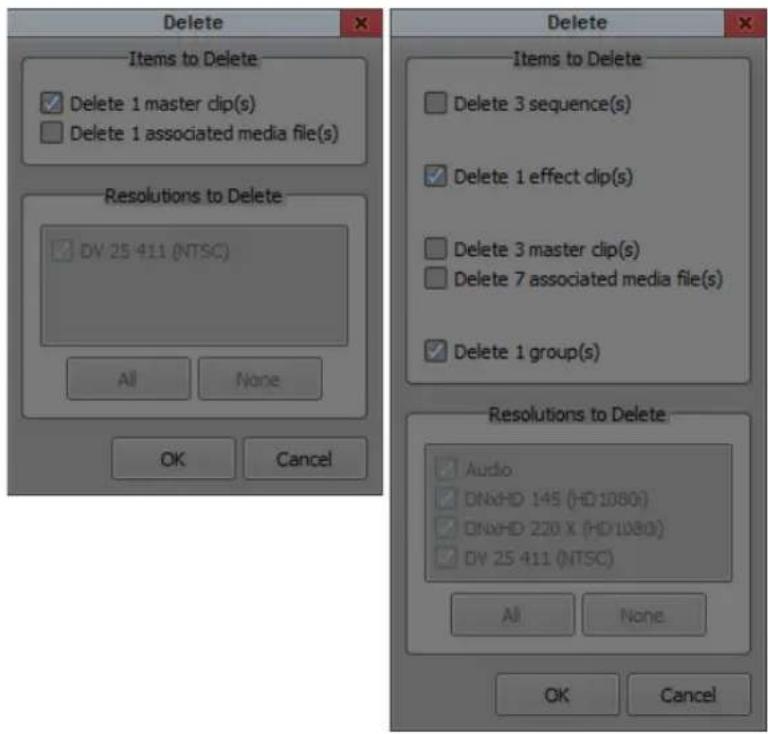
Examples of the Delete dialog box with one master clip selected (left) and with multiple clips selected (right)
- Select the items you want to delete:
▶Select clips and their associated media files for deletion.
▶ Select only the media files for deletion if you want to retain the clips to recapture later.
▶ Select only the clips for deletion (in case the media file is referenced by other clips in your project).
▶Select the resolutions you want to delete.
The Resolutions to Delete section lists all video resolutions for the clips you selected. It also lists a single entry for all audio sample rates and compressed audio and a single entry for the data (ancillary data) file. Click All to delete all resolutions. However, you still need to select the individual media files that you want to delete. If you don't want to delete any media files, click None, and all media files are deselected.
The options in this section also let you delete only audio media, only data media or only video media from a clip, if that clip has separate media files for audio, data and video.
- Click OK.
If you choose to delete media files, a dialog box opens.
- Click Delete.
The selected clips, sequences, and media file are deleted.

When you select a title for deletion, you might see more than one resolution.
(Macintosh) To delete clips, subclips, and sequences with their media files from a bin:
- Select the clips, subclips, or sequences you want to delete.
- Do one of the following:
▶Select Edit > Delete.
▶Press the Delete key.
The Delete dialog box opens which displays information about the selected items.
- Select the items you want to delete.
▶Select clips and their associated media files for deletion.
▶ Select only the media files for deletion if you want to retain the clips for recapturing later.
▶ Select only the clips for deletion if the media file is referenced by another clip.
- Click OK.
If you choose to delete media files, a dialog box opens.
- Click Delete.
The selected clips, sequences, and media file are deleted.
Changing the Bin Background Color
You can customize the background color of the bin. Changes affect only the currently active bin. Also, you can reset the bin background color to the default color for your Interface settings.
To change the bin background color:
- In the Settings list of the Project window, double-click Interface.
The Interface Settings dialog box opens. - Select Allow Custom Bin Backgrounds, and then click OK.
- Activate the bin you want to change.
In Text view, make sure no clips are selected.
- Select Edit > Set Bin Background and click a color.

The bin color changes. The change applies to all bin views.
To restore the default bin background color, do the following:
▶ Activate the bin you want to change, and then select Edit > Set Bin Color to Default.
Assigning Colors to Objects in a Bin
You can assign colors to clips, subclips, sequences, and effect clips to help you manage and organize the bin objects. You can also display colors in bins and in the Timeline. For information on displaying colors in the Timeline, see “Displaying Clip Colors in the Timeline” on page 672.
Also, you can reset the clip color to the default color for your Interface settings.

Clip colors assigned to sequences, groups, motion effects, and title clips do not appear in the Timeline.
To add a Color column to a bin:
- With a bin in Text view, select Bin > Choose Columns.
The Bin Column Selection dialog box opens. - In the column list, click Color.
- Click OK.
The Color column appears in the bin. By default, a new column appears as the first column in the bin, to the left of all other columns. You can reposition the Color column by clicking the column heading and dragging it to a new location.
To assign a color to a clip, subclip, sequence, or effect clip in a bin:
- With a bin in Text view, select the bin objects to which you want to assign a color.
- Do one of the following:
▶Select Edit > Set Clip Color and click a color.
▶Right-click in the Color column and click a color.
Alt+right-click (Windows) or Option+Command+click (Macintosh) in the Color column in the bin, and then select one of the colors from the color picker.
The color appears in the Color column (Text view only).
To reset clip color to the default, do one of the following:
▶Select Edit > Set Clip Color and click None.
▶Right-click in the Color column and click None.
Locking and Unlocking Items in a Bin
You can lock any items in a bin — including source clips, master clips, subclips, and sequences — to prevent deletion. When you lock clips in a bin, you lock their associated media files on your desktop as well.
To lock items:
- Click a clip, subclip, or sequence to select it. Ctrl+click (Windows) or Cmd+click (Macintosh) additional clips, if necessary.
- Select Clip > Lock Bin Selection.
A Lock icon appears for each locked clip in the Lock column of the bin in Text view.
If the Lock column does not display, you might have the column hidden. For information on hiding and restoring bin columns, see “Moving, Aligning, and Deleting Bin Columns” on page 346.
| Boston clips | ||||
| Name | Lock | Creation Date | Duration | |
| □ □ □ □ □ □ □ □ □ □ □ □ □ □ □ □ □ □ □ □ □ □ □ □ □ □ □ □ □ □ □ □ □ □ □ □ □ □ □ □ □ □ □ □ □ □ □ □ □ □ □ ▢□□□□□□□□□□□□□□□□□□□□□□□□□□□□□□□□□□□□□□□□□□□□□□□□□□□□□□□□□□□□□□□□□□□□□□□□□□□□□□□□□□□□□□□□□□□□□□□□□□□□○ □ □ □ □ □ □ □ □ □ □ □ □ □ □ □ □ □ □ □ □ □ □ □ □ □ □ □ □ □ □ □ □ □ ▢ 4/26/2006 18:22:47 2:06 4/26/2006 18:30:17 2:06 4/26/2006 18:20:51 2:10 4/26/2006 18:21:49 2:10 4/26/2006 18:21:54 2:10 4/26/2006 18:30:17 2:10 4/26/2006 18:30:17 2:10 4/26/2006 18:30:17 2:10 4/26/2006 18:30:17 2:10 4/26/2006 18:30:17 2:06 4/26/2006 18:30:17 2:12 4/26/2006 18:30:17 2:12 4/26/2006 18:30:17 2:12 4/26/2006 18:30:17 2:13 4/26/2006 18:30:17 2:13 4/26/2006 18:30:17 2:13 4/26/2006 18:30:17 2:14 4/26/2006 18:30:17 2:14 4/26/2006 18:30:17 2:15 4/26/2006 18:30:17 2:15 4/26/2006 18:30:17 2:15 4/26/2006 18:30:17 2:15 4/26/2006 18:30:17 2:15 4/4/26/2006 18:30:17 2:15 4/4/26/2006 18:30:17 2:15 4/4/26/2006 18:30:17 2:15 4/4/26/2006 18:30:17 2:58 4/4/26/2006 18:30:17 2:58 4/4/26/2006 18:30:17 2:58 4/4/26/2006 18:30:17 2:58 4/4/26/2006 18:30:17 4/4/26/2006 18:30:17 2:58 4/4/26/2006 18:30:17 2:58 4/4/26/2006 18:30:17 2:58 4/4/26/2006 18:30:17, 2.58 4/4/26/2006 18:30:17, 2.58 4/4/26/2006 18:30:17, 2.58 4/4/26/2006 18:30:17, 2.58 4/4/26/2006 18:58, 2.58 4/4/26/2006 18:58, 2.58 4/4/26/2006 18:58, 2.58 4/4/26/2006 18:58, 2.58 4/4/26/2006 18:58, 2,58 4/4/26/2006 18:58, 2.58 4/4/26/2006 18:58, 2.58 4/4/26/2006 18:58, 2.58 4/4/26/2006 18:58, 2.58 ○ ○ ○ ○ ○ ○ ○ ○ ○ ○ ○ ○ ○ ○ ○ ○ ○ ○ ○ ○ ○ ○ ○ ○ ○ ○ ○ ○ ○ ○ ○ ○ ○ ○ ○ ○ ○ ○ ○ ○ ○ ○ ○ ○ ○ ○ ○ ○ ○ ○ ○ × × × × × × × × × × × × × × × × × × × × × × × × × × × × × × × × × × × × × × × × × × × × × × × × × × × √ √ √ √ √ √ √ √ √ √ √ √ √ √ √ √ √ √ √ √ √ √ √ √ √ √ √ √ √ √ √ √ √ √ \urow \urow \urow \urow \urow \urow \urow \urow \urow \urow \urow \urow \urow \urow \urow \urow \urow \urow \urow \urow \urow \urow \urow \urow \urow \urow \urow \urow \urow \urow \urow \urow \urow \urow \urow \urow \urow \urow \urow \urow \urow \urow \urow \urow \urow \urow \urow \urow \urow \urow \urow | ▢ ▢ ▢ ▢ ▢ ▢ ▢ ▢ ▢ ▢ ▢ ▢ ▢ ▢ ▢ ▢ ▢ ▢ ▢ ▢ ▢ ▢ ▢ ▢ ▢ ▢ ▢ ▢ ▢ ▢ ▢ ▢ ▢ ▢ ◯ ◯ ◯ ◯ ◯ ◯ ◯ ◯ ◯ ◯ ◯ ◯ ◯ ◯ ◯ ◯ ◯ ◯ ◯ ◯ ◯ ◯ ◯ ◯ ◯ ◯ ◯ ◯ ◯ ◯ ◯ ◯ ◯ ◯ ✉ ✉ ✉ ✉ ✉ ✉ ✉ ✉ ✉ ✉ ✉ ✉ ✉ ✉ ✉ ✉ ✉ ✉ ✉ ✉ ✉ | ||||
To unlock previously locked items:
- Select the items in the bin.
- Select Clip > Unlock Bin Selection.
You can use the clip-locking feature along with archiving software to automatically archive all locked media files.
Selecting Offline Items in a Bin
Offline items are clips, subclips, or sequences that are missing some or all of their original media files or that have never been captured.
To identify offline items, do one of the following:
▶Select Bin > Select Offline Items.

▶Click the Bin Fast Menu button, and then select Select Offline Items.
The bin highlights all items that are missing media files. To identify offline items in the Timeline, see “Displaying Clip Colors in the Timeline” on page 672.
Selecting Media Relatives for an Object in a Bin
When you identify media relatives of a selected clip or sequence, your Avid editing application highlights all other clips linked to the selected clip, such as subclips or other sequences.
You can also use the Media tool to look at the captured video and audio data files stored on your media drives. For more information on the Media tool, see “Using the Media Tool” on page 443.
To identify media relatives:
- Open the bin that contains the selected clip or sequence.
- Open any other bins that might contain the media relatives that you want to find.
- Resize and position the bins so that you can see their contents.
Text view is the best display for viewing as many objects as possible.
- Select the clip or sequence, and select Bin > Select Media Relatives.
The system highlights all related objects in all open bins.
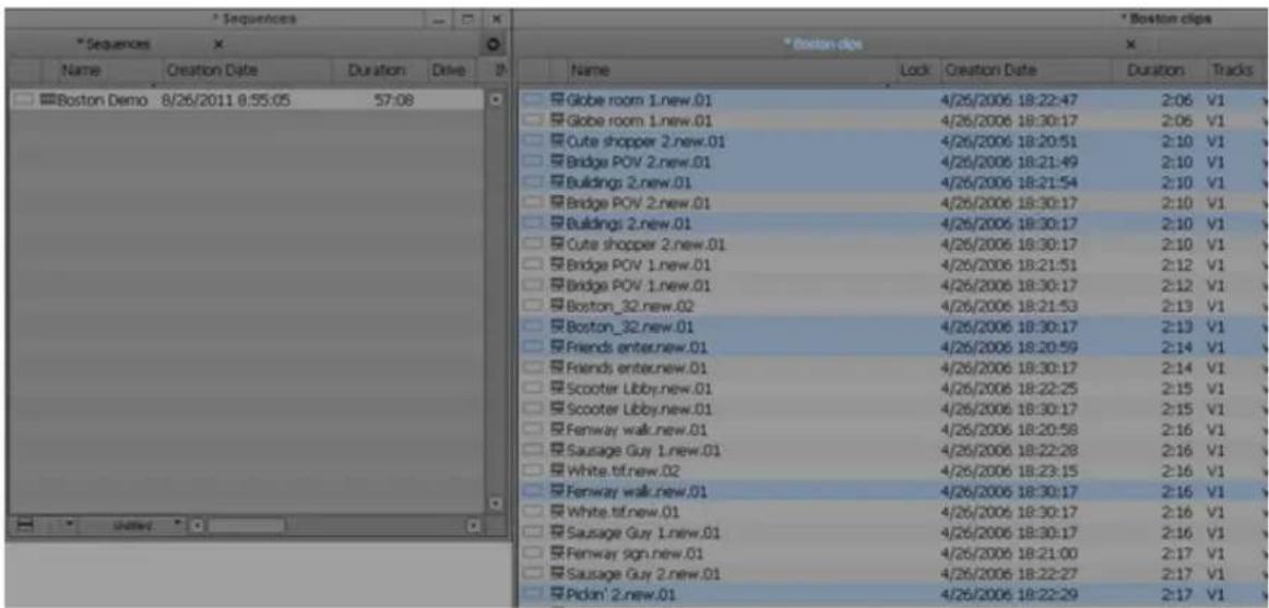
Example of finding media relatives. In the bin on the right, objects are highlighted if they relate to the sequence selected in the bin on the left.
Selecting Sources Used by an Object in a Bin
The Select Sources command identifies all the sources used by a particular object. For example, if you select a sequence as the object, the Select Sources command identifies every master clip, subclip, tape, and media file that is a source for that sequence.
To identify sources for a clip or sequence:
- Select one or more objects in a bin.
- Select Bin > Select Sources.
All sources for the selected objects in all open bins highlight.
Selecting Unreferenced Items in a Bin
When you select unreferenced clips, your Avid editing application highlights all clips not currently referenced by clips or sequences that are in the open bins. Any master clips, subclips, or effect clips you edited into sequences in the bins do not highlight.

The Select Unreferenced Clips option is useful for finding unused media.
To identify unreferenced clips:
- Open the bin containing the sequence or clip that is referenced.
- Open all other bins containing clips that were used during editing.
- Select Bin > Select Unreferenced Clips.
A message informs you that unreferenced clips highlight in open bins only (items in closed bins do not display).
- Click OK.
All unreferenced clips highlight in the open bins.
Working with Bin Columns
The topics in this section describe how to work with the columns of information that appear in the bin when you are in Text view.
For more information on Text view, see “Using Text View” on page 325. For information on modifying the information that appears in bin columns, see “Modifying Clip Information” on page 352.
Moving, Aligning, and Deleting Bin Columns
You can move, align, and delete columns in a bin.
When you align bin columns, the system maintains the same order of columns from left to right but spaces them according to the length of their contents. This is useful to remove spaces which remain after you move or rearrange columns.
When you delete a statistical column it is the same as hiding the column; you can restore the column at any time by using the Bin Column Selection option. When you delete a custom column, however, you must re-create the column.
For information to display and hide column headings in the bin, see “Using Text View” on page 325.
To move a text column in a bin:
- Click the heading of the column that you want to move.
The column is highlighted.
- Drag the column to the position you want, and release the mouse button.
A bounding outline of the column guides you as you drag it. The column appears in the new position, and columns to the right move to make room.
To align bin columns:
▶Select Bin > Align to Columns.
To hide or delete a column:
- Do one of the following to hide a column:
Click the column heading in a bin, and then select Bin > Hide Column.
▶Right-click a column heading and select Hide Column.
The column disappears from the view, and surrounding columns close to fill the space.
- Do one of the following to delete a column:
▶ Click the column heading in a bin, and then select Edit > Delete.
Click the column heading in a bin, and then press the Delete key.
The column disappears from the view, and surrounding columns close to fill the space.
- When you delete a custom column, a confirmation dialog box opens. Select OK to delete the column or HIde to hide the column and save the custom information.

If you delete a custom column, all information in the column is deleted. You must re-create the column to restore it.
Duplicating Bin Columns with Timecode Information
You can duplicate existing columns containing timecode information into other compatible columns that you target.
When you duplicate a timecode column (Start, TC 24, TC 25, TC 25P, or TC 30), the values for master clips and subclips convert to the appropriate timecode. For more information, see “Displaying Timecodes in a 24p or 25p Project” on page 350.
To duplicate a timecode column:
- Click the column head you want to duplicate.
- Select Edit > Duplicate.
The Select dialog box opens.
- Select a column name from the list.
The column must contain the same type of data for the copy to occur. For example, you can copy start timecodes to the Auxiliary TC column, but you cannot copy timecodes to the Pullin column.
- Click OK.
The column of information appears in the column you designated.
Adding Customized Columns to a Bin
In addition to the standard column headings, you can add your own column headings to describe information about clips and sequences. For example, you might want to add a column heading to describe what kind of shot (close-up, wide shot, master shot, extreme or close-up) is used in a clip.
To add a new custom column:
- Move any existing column to the right or left to create an empty area.
Move the column partly over the adjacent column. If you move the column too far, the column repositions.
- Click an empty area to the right of the current headings in the headings box.
A text box appears.
- Type the column heading you want, and press Enter (Windows) or Return (Macintosh).
Column headings must contain a maximum of 14 characters, including spaces.
This places the pointer in the data box, beside the first clip in the bin.
-
Select Bin > Align to Columns after you enter the new column heading.
-
Type the information, and press Enter (Windows) or Return (Macintosh) to move to the next line.
Changing a Custom Bin Column Heading
You can change the heading name of custom columns only. You cannot change any of the standard column headings.
To change the name of a custom column:
- Press and hold the Alt key (Windows) or Option key (Macintosh), and click the heading to highlight it.
- Type the new text for the heading, and press Enter (Windows) or Return (Macintosh).
Adding a Metadata Bin Column Heading
When you use the Avid Media Access (AMA) method to link to third-party media, each manufacturer has its own metadata information associated with the media. Avid displays this information in customized bin columns. The headings can include: Manufacturer, Data Source, Creation Date, and Last Update. The headings change depending on the manufacturer. After the media links into a bin, the metadata bin column headings appear at the bottom of the Bin Headings list, separated by a divider.
For information about AMA, see “Acquisition of File-Based Media (AMA)” on page 374.
To add a metadata column:
- With a bin in Text view, select Bin > Choose Columns.
The Bin Column Selection dialog box opens.
- Scroll to the bottom of the list and select the metadata headings you want to add to the bin.
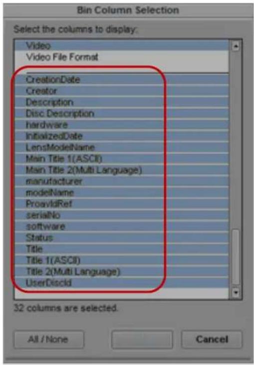
Manufacturer generated metadata column headings in the Bin Column Selection dialog box
3. Click OK.
Only the metadata headings selected appear in the bin.

When you use AMA and metadata column headings, Avid recommends that you do not create custom bin views. Use the default preset bin views.
Moving Within Column Cells
You can use the keyboard shortcuts described in the table to move from cell to cell in bin columns:
Shortcut Description
Tab Moves the pointer to the cell in the next column. You can continue to press the Tab key to move through the cells to the right until the cell in the last column highlight. The next time you press the Tab key, the cell in the first column highlights.
Shift+Tab Moves the pointer left to the cell in the previous column. You can continue to press Shift+Tab to scroll through cells to the left until the cell in the first column highlights. The next time you press Shift+Tab, the cell in the last column highlights.
Shortcut Description
| Enter (Windows, on main keyboard) or Return (Macintosh) | Enters any new information you type in the cell and moves the pointer down to the cell in the next row. You can continue to press Enter or Return to scroll down the column until the last cell in the column highlights. The next time you press Enter or Return, the first cell in the column highlights. |
| Shift+Enter (Windows, on main keyboard) or Shift+Return (Macintosh) | Moves the pointer up to the cell in the previous row. You can continue to press Shift+Enter or Shift+Return until the cell in the top row highlights. The next time you press Shift+Enter or Shift+Return, the cell in the last row highlights. |
Copying Information Between Columns
To copy column information to another column:
- (Option) If you want to copy only the information on specific rows, select the rows that contain the clip information you want to copy.
- Select the column that you want to copy.
- Select Edit > Duplicate.
The Select dialog box opens, to prompt you to target a column for the data. - Select the target column for the data, and click OK.
Displaying Timecodes in a 24p or 25p Project
When you work with 24p and 25p projects (PAL with pulldown), you can add timecode columns to bins or the Media tool to enter and display starting timecodes in several timecode formats for master clips, subclips, and sequences.

For information to display timecodes in the Timeline and the Tracking Information display, see “Displaying Timecode Tracks in the Timeline” on page 677 and “Displaying Tracking Information” on page 490.
After you add a timecode column (TC 24, TC 25, TC 25P, TC 30, or TC 30NP) to a bin, you can use the Duplicate command to convert the values for master clips and subclips to the appropriate timecode for that column.
For example, when you work with a 24p NTSC project, if you duplicate the Start column values to one of the timecode columns and the Start column contains a master clip with the timecode 01:00:00:15, the timecode converts to the timecode of that column.

The TC1 track in the Timeline represents the timecode of the project in which you work. For example, when you work in a 24p NTSC project, the TC1 track displays the same timecode as the TC 30 track.
Adding Timecode Columns to a Bin or the Media Tool
To add timecode columns to a bin or to the Media tool:
- Select Bin > Choose Columns.
The Bin Column Selection dialog box opens.
- Ctrl+click (Windows) or Command+click (Macintosh) the timecode columns you want to display.
- Click OK.
The timecode columns appear in the bin or the Media tool.
Frame Counting for Timecodes
The table shows the frame count for each timecode available for your Avid editing application. The timecodes are listed as 24 for 24 fps, 25 for 25 fps, 25P for 25 PAL with pulldown, 30 for 30 fps (the count skips six frames to fit 30 frames into 24 fps), 30NP for 30 fps with no pulldown, and 60 for 60 fps.
Timecode Frame Count
| 24 00 01 02 03 04 05 06 07 08 09 10 11 12 13 14 15 16 17 18 19 20 21 22 23 00 |
| 25 00 01 02 03 04 05 06 07 08 09 10 11 12 13 14 15 16 17 18 19 20 21 22 23 24 |
| 25P 00 01 02 03 04 05 06 07 08 09 10 11 13 14 15 16 17 18 19 20 21 22 23 24 00 |
| 30 00 01 03 04 05 06 08 09 10 11 13 14 15 16 18 19 20 21 23 24 25 26 28 29 00 |
| 3 0 N P 0 0 0 1 0 2 0 3 0 4 0 5 0 6 0 7 0 8 0 9 1 0 1 1 1 2 1 3 1 4 1 5 1 6 1 7 1 8 1 9 2 0 |
Adding Timecode Values to the Timecode Columns
To add timecode values to the timecode columns:
- Open a bin or the Media tool.
- Add the Start column and the timecode column with the format you want to use.
- Select the Start column.
- Select Edit > Duplicate.
The Select dialog box opens.
- Select the timecode heading from the list.
- Click OK.
The values for master clips, subclips, and sequences in the Start column convert to the appropriate timecode format and display in the column you selected.
Modifying Clip Information
You can change or modify the information in certain columns for your master clips, subclips, tapes, and other objects stored in the bin. This is useful if some of the data is incorrect or if you need to conform information for organizational purposes.
The following conditions apply to modifying clip information:
- When you modify a clip's information, related objects automatically update to reflect the new data. For example, if you change the name of a clip, the updated name appears in the sequences that use the clip.
- You cannot modify some data after capture because changes would prevent you from playing back and editing the material successfully.
- You cannot change sequence data even though it appears in your bin. The only way to modify sequence data is to edit the sequence itself. You can, however, change the name and start time for the master timecode track, as described in “Changing the Name and Timecode for a Sequence” on page 577.
You can modify data in two ways:
- Modify some data directly for master clips, subclips, and other objects stored in a bin.
- Use the Modify command to change specific information for master clips only.
For more information, see “Modifying Data in Bins” on page 358.
Bin Column Headings
You can select individual or multiple headings to display or hide in a bin. For information on how to select column headings, see “Moving, Aligning, and Deleting Bin Columns” on page 346.
Your Avid editing application provides the ability to track multiple film gauges within a bin and within a sequence. Bin column headings let you display detailed information about edgecodes, film gauges, and source information such as scanned file type, color lookup table, and resource location.
If you work in an Interplay environment, the list of bin column headings include audio sample rates and video resolutions. Select from these headings to display multiple sample rates and resolutions in the bin. For more information, see “MultiRez Bin Headings” on page 1281.
You can modify information in bin columns. For example, you can type a new name for a clip or correct the start and end timecodes. For more information, see “Modifying Data in Bins” on page 358 and “Modify Command Options” on page 360.
You can modify any data in the bin even while you log, prior to capture. After the footage is captured, however, you can modify information only in selected headings, with restrictions. For more information, see the following table.

When you modify tape names and timecodes, the modification affects any key numbers you enter for the selected clips.
The following table describes all bin column headings available in Avid editing applications, including information on which bin columns you can modify after you have captured footage. Depending on the model of your Avid editing application, you might not see all column headings.
Bin Column Heading Description
| Name Heading always appears in the bin. The column contains the name of the clip or sequence (you can rename a clip or sequence after you capture it). Modifiable after capture with no restrictions. | |
| Aspect Ratio Indicates the shape of the image frame. Ratio of width to height. | |
| Audio Bit Depth Use audio bit depth when you work with audio files: 16 bit or 24 bit. | |
| Audio Format Audio format of master clips (AIFF-C or WAVE). | |
| Audio SR Audio resolution (sample rate). | |
| Aux TC 24 Original HDTV sources (1080p/24) or audio DATs created for PAL feature film productions that use in-camera timecode. | |
| Auxiliary Ink Auxiliary ink format settings let you display an additional type of ink number.This lets you track additional types of film information for different film gauges.Used for 24p projects, 25p projects, and matchback projects only. Auxiliary Ink is the starting frame for the clip. | |
| Auxiliary TC1 through TC5 | You can enter an auxiliary timecode, such as Aaton® or Arri, or another timecode for editing film or audio timecode for film. (Not restricted to film projects.) Modifiable after capture with no restrictions. |
| AuxInk Dur Length of the clip, expressed in the auxiliary ink number. You cannot modify this number. | |
| AuxInk Edge | Type of edgecode used in the auxiliary ink number. Ctrl+click the cell, and then select the type of edgecode. See “Selecting an Edgecode Type” on page 365. |
Bin Column Heading
Description
AuxInk End Ending auxiliary ink number for the clip. You cannot modify this number.
AuxInk Film Film gauge for the auxiliary ink number. Ctrl+click the cell, and then select the gauge. See “Selecting a Film Gauge” on page 364.
Cadence Type of pulldown present on the source NTSC tapes when in a 23.976 or 24p project.
Modifiable after capture (Ctrl+click and choose from the menu). All clips with the same tape name change according to your selection.
Camera Camera used to film this clip. This feature is used in multicamera shoots.
Camroll Camera roll containing this clip. Used for 24p projects, 25p projects, and matchback projects only.
CFPS Captured frames per second.
Color Color of the bin objects for organizing the objects. For more information, see "Assigning Colors to Objects in a Bin" on page 341. Modifiable after capture with no restrictions.
Color Framing The color framing for the tape. For NTSC, the choice is Even or Odd. For PAL, the choice is A Standard, A Non-Standard, B Standard, or B Non-Standard.
Modifiable after capture in accordance with tape specifications. For more information, see “Tracking Color Frame Shifts” on page 728.
Color Space Indicates the color space (RGB or YUV) of the clip.
Comments Modifiable after capture with no restrictions.
Creation Date Date and time you log or capture the clip.
Disk Label For XDCAM media, this heading displays the user-supplied disk label you create when you import the media file. For other media, the heading displays the disk label of the drive from where you imported the clip. For more information, see “Importing XDCAM Media” on page 304.
DPX Frame-counting field for Digital Picture Exchange, a SMPTE standard describes frames scanned from film. The format includes: a descriptor of up to 32 alphanumeric characters, followed by a hyphen (-), followed by a six-digit frame count, for example, DPXChildDocu-023657.
Drive Last known drive where the media for the master clip existed.
Duration Length of the clip.
End Timecode of the clip's tail frame.
Bin Column Heading
Description
Field Motion Sets the default source parameter value for the Motion Adapter effect.
Film TC Timecode you use on film. For 24p and 25p projects only.
Format The format of a clip or sequence which you determine by the project type, such as 30i NTSC or 1080i/59.94. This is useful if you have both SD and HD clips in the same bin.
FPS Play rate: the number of frames that display each second. The default is 29.97 for NTSC and 25 for PAL for video. The play rate is also 24 or 23.98.
Frame Displays the same frame that displays when you select Frame view. See “Using Frame View” on page 330.

It takes longer for the screen to display frames than text.
IN-OUT Length of the marked segment.
Ink Dur Displays the length of the clip, in ink number. For 24p projects, 25p projects, and matchback projects only. You cannot modify this number.
Ink Edge Type of edgecode you use in the ink number. See “Selecting an Edgecode Type” on page 365.
Ink End Ending ink number for the clip. You cannot modify this number.
Ink Film Film gauge for the ink number. See “Selecting a Film Gauge” on page 364.
Ink Number Ink number for the clip. For 24p projects, 25p projects, and matchback projects only.
Journalist First and last name of a person associated with the clip. Metadata information from a P2 file. Modifiable after capture with no restrictions.
KN Dur Length of the clip, expressed in feet and frames.
KN End Ending key number for the clip.
Modifiable after capture only for 24p, 25p, and matchback projects. If you alter the starting key number, you also alter the KN Start to maintain the duration.
KN Film Key number film gauge. See “Selecting a Film Gauge” on page 364.
KN IN-OUT Mark IN and Mark OUT key number for the clip.
KN Mark IN Key number for the IN point, if you set one for the clip.
KN Mark OUT Key number for the OUT point, if you set one for the clip.
Bin Column Heading
Description
KN Start Starting key number for the clip.
Modifiable after capture only for 24p, 25p, and matchback projects. If you alter the starting key number, you also alter the KN End to maintain the duration. This causes discrepancies with any auxiliary timecode information that you enter manually.
Labroll Labroll containing the clip.
Lock Specifies whether the clip is locked from deletion.
LUT File name of the color look-up table used for the series of clips or frames.
Mark IN Timecode for the IN point, if you set one for the clip.
Modifiable after capture — altering the mark IN also alters the IN to OUT duration. This replaces any previous mark.
Mark OUT Timecode for the OUT point, if you set one for the clip.
Modifiable after capture — altering the mark OUT also alters the IN to OUT duration. This replaces any previous mark.
Master Dur Length of the final master sequence, expressed in feet and frames. You cannot modify this number.
Master Edge Type of edgecode used in the final master sequence. See “Selecting an Edgecode Type” on page 365.
Master End Ending key number for the final master sequence. You cannot modify this number.
Master Film Gauge of the final master sequence. See “Selecting a Film Gauge” on page 364.
Master Start Starting key number of the final master sequence.
Media Status Status of the media in the export Volume Bin. See “Working with Export Volumes” on page 430.
Modified Date Date and time a sequence was last edited or changed.
Offline Track names for any media files offline.
Perf Film edge perforations format used for 3-perf projects.
Pixel Aspect Ratio Indicates the shape of each pixel in the image. Ratio of width to height.
Bin Column
Heading Description
Production Name of the production associated with the clip. Metadata information from a P2 file.
Modifiable after capture with no restrictions.
Project Project under which the media was originally captured.
Pullin Telecine pulldown of the first frame of the clip (pulldown phase). Pullin can have the values A, B, X (matchback only), C, or D. For 24p projects and matchback projects only. (NTSC only)
Modifiable after capture only for 24p projects and matchback projects. You can only alter pullin data imported from a telecine-generated list directly before you capture or after you unlink. For more information, see “Modifying the Pulldown Phase Before Capturing” on page 154. (NTSC only)
You can directly modify the pullin for sequences. For more information, see “Changing the Default Pulldown Phase for Sequences” on page 1082.
Pullout Telecine pulldown of the last frame of the clip. Pullout can have the values A, B, X (matchback only), C, or D. For 24p projects and matchback projects only. (NTSC only)
Reel # Source reel number.
Reformatting Options Set the media conversion mode to use when working with media of different sizes and aspect ratios in the same sequence.
Scene Scene number of the clip.
Shoot date Date you shot the footage. Modifiable after capture with no restrictions.
Slip Number and direction of perfs for subclips (audio clips only).
Sound TC Timecode for audio.
Soundroll Sound roll the clip came from. Modifiable after you enter a soundroll.
Source File Specifies the source file name.
Source Path Specifies the location of resources on local or remote storage using Universal Naming Convention (UNC).
Start Timecode of the clip's head frame. Modifiable after capture with no restrictions.
Take Take number of the scene. Modifiable after capture with no restrictions.
Tape Source tape name.
TapeID Tape ID number. Modifiable after capture with no restrictions.
Bin Column Heading Description
TC 24 24-fps timecode. Modifiable after capture with no restrictions.
TC 25 25-fps timecode, no pulldown. Modifiable after capture with no restrictions.
TC 25PD 25-fps timecode with PAL pulldown. Modifiable after capture with no restrictions.
TC 30 30-fps timecode with 2:3 pulldown. Modifiable after capture with no restrictions.
TC 30NP 30-fps timecode with no pulldown (frames 00 through 29). Modifiable after capture with no restrictions.
Track Formats Multichannel audio tracks for master clips and audio clips.
Tracks All tracks used by this media object.
Transfer Frame-counting field for sources that you prepped for transfer. The format: a descriptor of up to 32 alphanumeric characters, followed by a hyphen (-), followed by a six-digit frame count, for example, TransferChildDocu-023657.
VFX Frame-counting field for visual effects. The format: a descriptor of up to 32 alphanumeric characters, followed by a hyphen (-), followed by a six-digit frame count, for example, FXChildDocu-023657.
VFX Reel Source reel identification for the FX shot.
Video Clip video format (resolution, color space and field motion type).
Vendor A list of vendor headings is provided for use with Avid Marketplace. See “Adding Vendor Columns to your Avid Bin” on page 1321.
Video File Format Clip video file format (OMF, AAF, MXF, or none).
VITC Vertical interval timecode.
Modifying Data in Bins
You can modify data in bin columns directly by typing in a selected text field. You can use the standard keyboard shortcuts for entering text — for example, press Ctrl+A (Windows) or Command+A (Macintosh) to select all text in a text field
You can also use the Modify command for specialized control over groups of clip information. For example, you can use the Modify command to change the name of source tapes, or to increment or decrement the start and end timecodes by a specified length of time for one or several clips at once.
You can apply changes with the Modify command to master clips only. You cannot alter subclips and sequences in this way. You can modify the data of captured, imported and file-based clips. In addition, you can perform modifications that only alter the end timecodes or the tracks before capture.

When you modify tape names and timecodes it affects any key numbers entered for the selected clips.
To modify the clip data directly in a bin:

- Click the Text View button in the bin to enter Text view.
- Click the cell that you want to modify. Select only one item at a time.
The timecode data highlights, as displayed in the following example.

- Click the cell again to enter text.
If the pointer does not change to an I-beam, you might be selecting a column that cannot be directly modified.
- Type the new information, and press Enter (Windows) or Return (Macintosh).
To modify selected data using the Modify command:

- Click the Text View button in the bin.
- Click the icon to the left of the clip, sequence, or other object you want to modify. Ctrl+click (Windows) or Cmd+click (Macintosh) each additional object you want to modify.
- Select Clip > Modify.
The Modify dialog box opens.
- Click the Modify Options menu, and select an option.
![Modify Set Timecode By Field Set Timecode DropNon-drop ✓ Set Timecode By Field Increment Timecode Decrement Timecode Set Key Number Generic [Prefix] Set Pullin Set Tracks Set Source Set Disk Label Set Format Set Multichannel Audio Set Ink Number Options Set Aux Ink Number Options Hours 0 Minutes 0 Seconds 0 Frames 0 OK Cancel](/content/2026/05/883817/images/b921a48b97f5918defa106e607c8fb159aa7d40d49603702cfb3a8406b1de015.jpg)
- Select an option or type information into the text boxes.
For more information, see "Modify Command Options" on page 360.
- Click OK.
The modification takes effect.
Modify Command Options
Type of Modification Options Description
| Set Timecode Drop/Non-drop | Drop, Non-drop Changes the timecode format between drop-frame and non-drop-frame. Setting must match the timecode format of the tape. |
| Set Timecode By Field Start or End Changes either the start or end timecode. You can only alter start timecodes after capture. | |
| Hour, Minutes, Seconds, Frames | Lets you enter custom timecode. |
| Type of Modification | Options | Description |
| Increment Timecode Start or End Changes either the start or end timecode. If you increment the start timecode automatically, it modifies the end timecode by the same amount. You can only alter start timecodes after capture.Timecode text box Lets you enter custom incremental timecode. | ||
| Decrement Timecode Start or End Changes either the start or end timecode. If you decrement the start timecode, it automatically modifies the end timecode by the same amount. You can only decrement start timecode after capture.Timecode text box Lets you enter custom decremental timecode. | ||
| Set Key Number Generic (Prefix) | Key Number text box Lets you enter a custom generic key number. Only for 24p, 25p, and matchback projects. | |
| Set Pullin A, B, C, or D Selects the pulldown phase to match to the timecodeentry (24p and matchback projects only). For more information, see “Setting the Pulldown Phase” on page 149.After you capture, the clip must be unlinked. See “Modifying the Pulldown Phase Before Capturing” on page 154. | ||
| Set Tracks V, A1, A2, A3, A4, A5,A6, A7, A8 and D track selector buttons | Changes the clip’s configuration of tracks (film projects only). You must unlink the clip. See “Unlinking Media Files” on page 475. | |
| Set Source None Opens the Select Tape dialog box. Selects another sourcetape name for the clips that should match the original source tape name. | ||
| Set Disk Label Set label Lets you change the name assigned to an XDCAM disk.For more information, see “Importing XDCAM Media” on page 304. | ||
| Set Format | Compatible formats | Lets you change the format of a sequence. The choice of formats is limited to the compatible frame rate of the current sequence. This option is useful if you work with downconverted HD material in an offline/online workflow. For more information, see “Changing the Sequence Format” on page 1515 and “Converting a 23.976p NTSC Sequence to 720p/23.976” on page 1518. |
Type of Modification Options Description
| Set Multichannel Audio | Mixed, Mono, Stereo | Lets you assign multichannel formats to audio tracks. For more information, see “Working with Multichannel Audio Tracks” on page 762. |
| Active Format Description | Active Format for 4x3, 16x9, or Use Project Format. | Lets you set the Active Format Description (AFD) in the data track. AFD information allows you to display the video of one aspect ratio on a display with another aspect ratio. See “Adding the Active Format Description to the Data Track” on page 1094” |
Copying Information from Another Cell in a Custom Bin Column
To copy information from another cell in a custom column:
- Press and hold the Alt key (Windows) or Option key (Macintosh) while you click in the destination cell to reveal a menu of all items entered in that column.
- Select the text from the menu.
The text appears in the cell.
Working with Film Information in Bins
The topics in this section cover several bin procedures that are specific to working with film material.
Film Scene Workflow
During the organizing phase, common practice on film productions is to organize the captured clips according to scene. This helps to simplify the work environment and keeps crowded bins to a minimum.
It is good practice to copy or duplicate clips as you reorganize them in bins. As a result, the original source clips remain in the appropriate dailies bin if you ever need to recapture according to source tape.
Organize scene bins according to the following basic workflow:
- Create one bin for each scene.
See “Creating a New Bin” on page 73.
-
Gather clips according to scene. Use one of the following optional procedures:
-
Copy clips for each scene from the capture bins into the appropriate scene bin.
- Duplicate the clips and then move the duplicates into the appropriate scene bin.
See “Duplicating, Copying, and Moving Clips and Sequences” on page 336.
- Sort, sift, and organize the clips within each scene bin.
Tracking Frames Based on File Name
Bins can display a digital file name for each frame in addition to key numbers, ink numbers, and other reference numbers. Tracking frames with the frame number is useful when using the film scanning process where each frame is an independent file. It is also useful when working with effects and animation processes that are dependent on a frame-based counting scheme. You can include the frame number when you generate a cut list using FilmScribe.
The naming and counting scheme consists of a prefix (8 character maximum), separated by a dash (-), and followed by 6 characters that count as total frames. For example,
FXS32v01-000001 identifies the first frame of a series of frames that belong to an FX shot for Scene 32 version 1. As the FX shot progresses during the creative process, the version number increases.

To compensate for offsets, you can subtract the number of header and information frames from 999999 when entering the frame number. For example, if the first frame of picture is 1 and there are 8 frames of header and identification frames you would enter FXS32v01-999993 for the frame number.
To display the frame count numbers in a bin and cut list:
- In the Film and 24p Settings dialog box, select Frame Count from the “Ink Number Default Edge Type” option or the “Auxiliary Ink Default Edge Type” option.
- In a bin, select Ink Number or Auxiliary Ink from the Bin Headings dialog box.
The Ink Number and Auxiliary Ink columns display the frame count numbers in the bin. - Open the bin in FilmScribe and choose Ink Number or Aux Ink options. Then generate the cut list.
The cut list includes the frame count numbers.
To display the frame count numbers above the Source or Record monitors in your Avid editing application:
- Follow the steps for displaying the frame count numbers in a bin.
- From the Tracking Information Menu above the monitor, select either Ink Number or Aux Ink.
Selecting a Film Gauge
The film gauge consists of the film size and either the number of perfs per frame (for 35mm and 65mm) or the number of frames per foot (for 16mm). You specify the gauge in any of the film-gauge columns (Aux Ink Film, Ink Film, and Master Film).

You cannot modify the KN Film column.
To specify the gauge of the film:
▶ Ctrl+click the cell, and then select one of the following film sizes and perf count or frame count:
- 35mm, 4 perf
- 35mm, 2 perf
- 35mm, 3 perf
- 35mm, 8 perf
- 16mm, 40 perf
- 16mm, 20 perf
- 65mm, 15 perf (used in IMAX ^ films)
- 65mm, 10 perf
- 65mm, 8 perf
- 65mm, 5 perf
- V i s ^ t a V i s i o n
Tracking 3-Perf Counts
You can track 3-perf counts in film projects. The perf value is an extension of the key number, and appears in the KN Start, Ink Number, and Aux Ink Number bin columns. A sample key number might look like this:
KJ 12 1234-3456-10.3
The “.3” at the end of the key number represents the perf value.
To specify the perf value:
▶Enter 1, 2, or 3 in the appropriate bin column cell.
Selecting an Edgecode Type
There is one edgecode per foot of film. You enter an edgecode type for a particular place on the film in any of the edgecode-type bin columns (Aux Ink Edge, Ink Edge, Master Edge).
Select the appropriate edgecode type for a clip so you can track frames in the Timecode window, above the Source/Record monitor, or in FilmScribe.
To select an edgecode type:
▶ Ctrl+click the cell, and select the edgecode type that matches the edgecodes on the film.
Edgecode Type Edgecode Format Sample Edgecode
Key Number XX NNNNNN NNNN+NN (Film type Film ID Feet on film+Frame in foot)
KL 43 5146-0152+00
Edgecode (4 count) NNN-NNNN+NN (Identifier-Feet on film+Frame in foot) 103-9025+03
Edgecode (5 count) NNN-NNNNN+NN (Identifier-Feet on film+Frame in foot) 203-09025+03
Frames
NNNNN
Creating a Storyboard
To create a storyboard:
- Synchronize picture and sound, convert audio timecode, and modify clip data.
- Set the bin display to show the media objects for the clips you want in your storyboard.
- Delete, move, copy, and sort clips to narrow down the clip selection.
- Select Frame view to display your storyboard in the bin.
- Rename clips to include additional information such as numbered ordering.
- Use the keyboard to step through each clip and display the reference frame you want to use for each clip.
- Select and drag one or several clips at a time to a new location to rearrange the clips in sequential order.
- Enlarge or reduce the size of the frames as necessary.
- Align the rearranged frames along invisible grid lines.
- (Option) Change the font and background color for the storyboard.
- When the storyboard is complete, select File > Save Bin.
- To print the storyboard, select File > Print Bin.
Setting the Bin Display
By default, your bins display all existing media objects except source clips and rendered effects. To reduce crowding in the bin and to display only those objects that you need to organize your project, you can display selected media objects.

You can also display bins as tabs in a common bin window. For more information, see “Using Bin Tabs” on page 334.
You can use the Set Bin Display option to display clips referenced by a sequence, even if the clips were not previously in the bin.
To set the bin display:
- Place a sequence in a new bin and click the bin.
- Select Bin > Set Bin Display.
The Set Bin Display dialog box opens.
- Select the object types that you want to see: master clips, subclips, sequences..
For information on the icons used to represent the different object types, see “Object Icons in Bins” on page 323.
- (Option) Accept the default or deselect “Show clips created by user” if you want to hide all objects except those created by the system.
- (Option) Select “Show reference clips” to automatically display objects that are referenced by sequences in the bin, whether those clips were previously in the bin or not.
- Click OK.
The bin displays objects according to your specifications.
Sifting Clips and Sequences
When you sift clips and sequences, the bin displays only those clips and sequences that meet a specific set of criteria. For example, you can do a custom sift to display only those clips containing the word “close-up” in the heading column. The Custom Sift dialog box provides six levels of criteria.
You can also sift on a timecode (or keycode) number within a specific range. For more information, see “Sifting Timecodes or Keycode Ranges” on page 371.
To sift clips or sequences:
- Select Bin > Custom Sift.
The Custom Sift dialog box opens.
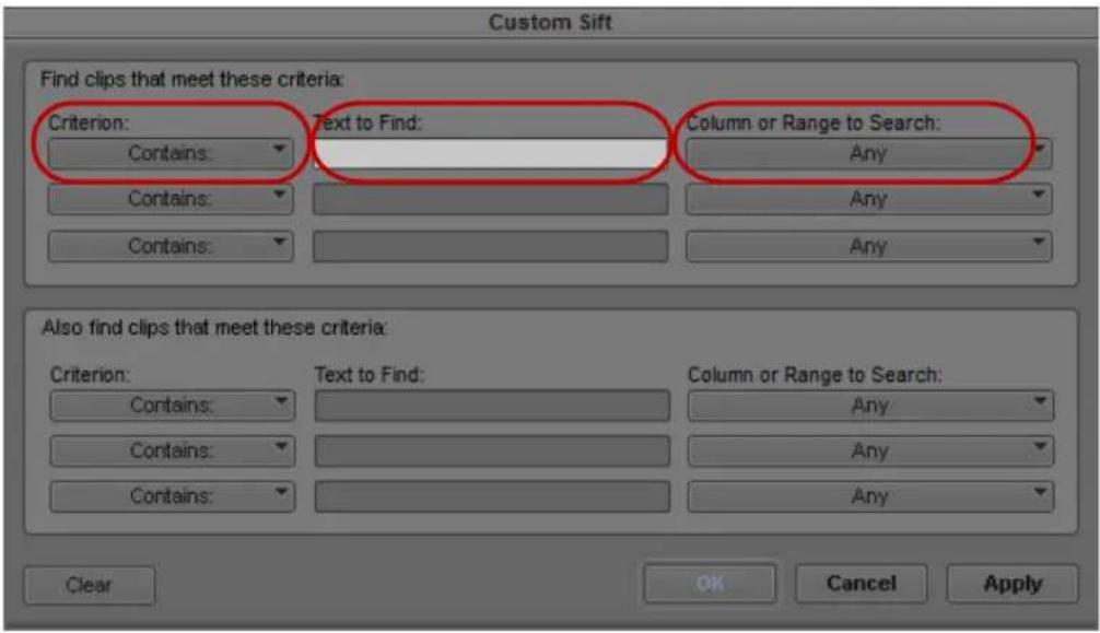
Custom Sift dialog box. Left to right: Criterion menu, Text to Find text box, and Column or Range to Search menu
- Click the Criterion menu, and select one of the sifting options.
- Click the first Text to Find text box, and type the text that you want to use as a sift criterion. When sifting by color, type the exact name of the color (using uppercase and lowercase letters) in the text box.
- Click the Column or Range to Search menu, and select a column heading to which you want to apply the criterion.
- Type additional sift criteria, and make additional column selections as necessary.
- Click OK.
Only the clips or sequences that meet your criteria remain in the bin, with the word "sifted" added to the bin name. After you have sifted the clips in a bin, you can display the bin in a sifted or an unsifted state.
To view the entire bin:
▶Select Bin > Show Unsifted.
To view the sifted bin:
▶Select Bin > Show Sifted.
The word “sifted” appears in parentheses after the bin name when you view the bin in its sifted state.
Understanding Sifting Timecodes or Keycode Ranges
You can sift on a timecode (or keycode) number within a specific range. For example, you can sift for all the clips that start before and end after a particular timecode.

Example of a bin before a custom sift by timecode
If you type a value in the Text to Find text box in the Custom Sift dialog box, click the Column or Range to Search menu, and select Start to End Range.

Example of a bin after a custom sift by timecode. The detail of the Custom Sift dialog box (top) shows the query used for sifting, and the bin (bottom) shows only those clips that encompass the timecode number entered.
Some column pairs explicitly define a range, for example, Start and End or Mark IN and Mark OUT. Other columns define the beginning of a range, and the end of the range is determined by the Duration column. For example, Auxiliary TC1 implies a range that begins at the value in the Auxiliary TC1 column and ends at that value plus the value in the Duration column.
If you display any column in the bin that is associated with ranges, either explicit or implicit, the corresponding range menu item appears in the Column or Range to Search menu in the Custom Sift dialog box. For example, if you choose to display the Start column and the Auxiliary TC1 column in the bin, the Start to End Range and Auxiliary TC1 Range menu choices appear in the Column or Range to Search menu.
When you specify a timecode or keycode number, you do not need to enter colons or semicolons, and you can omit the leading zero. For example, you can type 3172000 as a timecode number.
Keycodes contain letters, numbers, and a dash before the feet and frames; for example, KJ23 6892-0345+13. When you sift on a keycode number, you enter only the numbers after the dash (the actual counter portion). Any information before the dash is ignored. If you do enter characters before the dash, they must match the corresponding characters in the bin column exactly.
The table lists all columns associated with explicit ranges and their corresponding menu choices.
| Bin Column (Explicit Ranges) | Column or Range to Search Menu Item |
| Start, End Start to End Range | |
| Mark In, Mark Out Mark In to Out Range | |
| KN Start, KN End KN Start to End Range | |
| KN Mark In, KN Mark Out KN Mark In to Out Range |
The table lists all columns associated with implicit ranges and their corresponding menu choices. The Duration column determines the end of these ranges.
| Bin Column (Implicit Ranges) | Column or Range to Search Menu Item |
| Film TC Film TC Range | |
| Sound TC Sound TC Range | |
| Auxiliary TC1 Auxiliary TC1 Range | |
| Auxiliary TC2 Auxiliary TC2 Range | |
| Auxiliary TC3 Auxiliary TC3 Range | |
| Auxiliary TC4 Auxiliary TC4 Range | |
| Auxiliary TC5 Auxiliary TC5 Range | |
| Ink Number Ink Number Range | |
| Auxiliary Ink Auxiliary Ink Range |
Sifting Timecodes or Keycode Ranges
To sift for a timecode or keycode number within a specific range:
- Select Bin > Custom Sift.
The Custom Sift dialog box opens.
- Type the timecode (or keycode) number for the range in which you want to sift.
- Type the timecode number for the range in which you want to sift.
- Click the Column or Range to Search menu, and select a range; for example, Start to End Range or Mark In to Out Range.
The criterion “contain” appears in the Criterion menu. If you try to change this criterion, no information appears in the Column or Range to Search menu.
- Click OK.
The bin displays those clips that encompass the timecode (or keycode) number that you entered.
Working with Restricted Material
Broadcast facilities sometimes need to manage digital rights by restricting the use of footage. You can mark restrictions on clips in Avid Interplay Assist. When you bring marked footage into your Avid editing application, you can see the restriction marker (a red triangle) on the clip icons in the bin, and your Avid editing application warns you about the restriction before you display or output that footage.

Restriction marker on a clip in the bin
When you first open a restricted clip or load a sequence containing restricted clips, a warning message box opens. The warning appears every time you open or display a clip on restricted material in this session, not just on the present clip. The same warning appears when you try to perform a digital cut, send the sequence to playback, or export. If you send more than one clip to export, the message box lists all the clip names that contain restricted material.
You can use extended search capabilities to search for restrictions in Avid Interplay Access. For more information, see the Avid Interplay Access User's Guide. Search for the DRM (digital rights management) attribute, which can have the values Has DRM or Does not have DRM.
If you are allowed to use all restricted material in the current project and you can safely ignore the warning, you can continue with your editing or output task.
To ignore the warning for the rest of the editing session and continue with editing or output:
▶Click the “Don’t warn again” button.
Restriction warnings for the current clip or any other clip do not display. When you quit your Avid editing application and then open it, you see the warning again the first time you display or output restricted material.

If you select “Don’t warn again,” it stops the warning from appearing again only for the current operation in the current editing session. For example, if you select it after you display a clip in the Source monitor, you can load additional restricted clips without seeing the message. If you select those clips for Export, however, you see the warning again.

The restriction is tied to the source tape name and timecode. You can disassociate the restriction from the clip if you change those values in the bin.
To view Restriction comments, do one of the following:
▶ Click the View Restrictions button in the warning message box when it opens.
▶Select Tools > Restrictions.
The Restriction window opens. It displays the name, head frame, and description of each restricted clip. The description contains the comments associated with the restriction that you entered in Avid Interplay Assist.
To see changes in Restriction comments while you are editing:
- Change the comments in Avid Interplay Assist.
- In your Avid editing application, select Tools > Remote Assets.
- Navigate to the changed clip, and drag it into the bin again.
The changes appear in the Restriction window.
Printing Bins
To print entire bins:
- Make sure your printer is correctly set up.
- Select the Text, Script, or Frame bin view of the bin you want to print.
-
Select File > Page Setup.
The Page Setup dialog box opens, reflecting the specific options for your printer. -
Select the appropriate options.
-
Click OK (Windows) or Print (Macintosh).
-
Select File > Print Bin.
The Print dialog box opens, reflecting the specific options for your printer.
- Select the Print options.
- Click OK (Windows) or Print (Macintosh).
The system prints the active bin.
To print a single frame of a clip or sequence:
- Load a clip or sequence into the Source or Record monitor.
- Select the frame you want to print.
- Select File > Print Frame.
The Print dialog box opens. - Select the Print options.
- Click OK (Windows) or Print (Macintosh).
The system prints the frame currently displayed in the active monitor.
10 Acquisition of File-Based Media (AMA)
You can link, import, or export clips and sequences from many third-party volumes or third-party files to and from the Avid editing system. You can manipulate and edit this media as you would any other clip or sequence.
File-based media can be acquired from a third-party device (a camera, reader, or drive), from a CD or DVD, from a folder on your system, or from a virtual volume (a server connected to your system). To move the media into your Avid editing system, you have the option to use the AMA method (Avid Media Access) which links the file based media directly into a bin through an AMA plug-in, or you can use the non-AMA method which imports the media onto your system. When you work with high-resolution media, the AMA method is the preferred and the faster method.
AMA linking also allows for more metadata to be brought into the bin which gives you more information about the media. For example, essence marks (or markers) associated with the clip are automatically brought into your bin.

For information on importing and exporting media, see “Importing Files” on page 281 and “Exporting Frames, Clips, or Sequences” on page 1005.
Before you begin working with AMA, make sure you have done the following:
- Go to avid.com/ama to make sure you download the latest plug-in for your specific third-party device.
- If you are using an XDCAM, XDCAM EX or a P2 device, make sure you have the appropriate drivers installed. See your third-party documentation for information on installing drivers.
- Connect the third-party device according to the documentation supplied with the device.
The Avid Media Access (AMA) Workflow
Avid Media Access (AMA) is a plug-in architecture that lets you link directly to clips on an external third-party device. The device can be a camera, a card reader, an optical disk, a virtual volume. AMA lets you be more productive by browsing and editing directly from the device or volume.
There are two ways of browsing and editing this media:
- Manually browse through the media on the third-party device, and link to selected media to create master clips in your bin, or
- Move all the media from the third-party device to an Avid dynamic media folder where you have set up an automated process to create the master clips.
Typical media management functions (e.g. deletes, transcodes, consolidates) apply to all AMA-linked clips in the same robust manner as they do for managed MXF Avid-compliant OPAtom files. All media, whether captures, imported or linked by AMA, will be displayed in a single window in the Media Tool.
AMA and dynamic media folders are the quickest method by which you can automate the acquisition of footage, and significantly enhance your production workflow when working with media in popular digital formats.
With the use of dynamic media folders, you can organize your files and assign automated actions to a “watched” folder system. These actions run in the background, allowing you to keep working while files are being ingested into the application. The actions include copy, consolidate and transcode—see “Creating Dynamic Media Folders” on page 381.
The illustration below shows how you can automate the acquisition of file-based media in the background so that you can continue editing your sequence without interruption.
Before you begin editing, set up media service profiles to run automated media acquisition actions on the specific drives/folders where the original media is located. Any files placed in these folders will be processed and managed in the background.
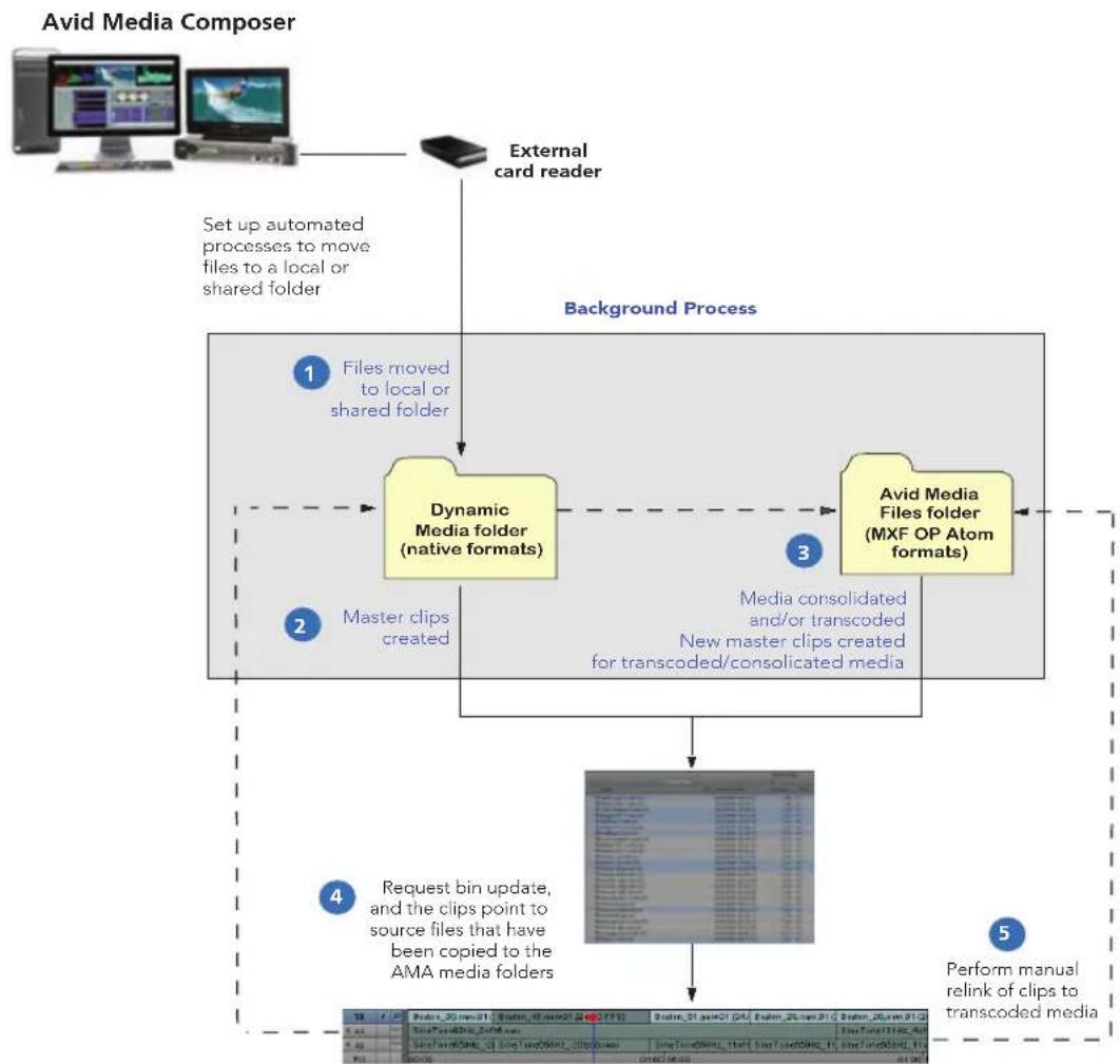
flowchart
graph TD
    A["External card reader"] --> B["Set up automated processes to move files to a local or shared folder"]
    B --> C["Dynamic Media folder (native formats)"]
    C --> D["Avid Media Files folder (MXF OP Atom formats)"]
    D --> E["Media consolidated and/or transcoded New master clips created for transcoded/consolidated media"]
    E --> F["Request bin update, and the clips point to source files that have been copied to the AMA media folders"]
    F --> G["Perform manual relink of clips to transcoded media"]
- You can begin the editorial by linking directly to the media on an external device. In the meantime, the pre-configured Dynamic Media Folder (DMF) profiles will automatically copy the files from the external device to an AMA media folder of your choice on a local or shared storage. These folders will be managed and indexed by the application.
- Master clips will be created for all the copied files and added to a 'staging' area so as not to cause interruptions each time a new file is acquired. Any related audio and video files will be auto-synced. Similarly, any related clips coming from multiple cameras will be auto-grouped.
-
Depending on how your dynamic media folders were configured, some specific file formats will be consolidated and/or transcoded to MXF proxy media. This media will be placed in the Avid MediaFiles folder and separate master clips (*.new) will be created in the bin for this media.
-
When files are ready to be pulled into a bin, you will be notified by a green light to the right of the audio meters in the timeline. Through the Dynamic Media Folders dialog, you can request a bin update which will pull the clips into a bin.
Any AMA-linked clips already on the timeline will automatically point to the new location of the media in the designated AMA media folder(s). Similarly, if any files were consolidated, and you selected the “relink” option in the DMF dialog, the master clips will automatically point to the new consolidated files.
- If you want to work with transcoded media, on the other hand, you need to manually relink your sequence to the new master clips in the bin.

In an Interplay environment, the relink can be done automatically. See “Enabling Dynamic Relink” in the online help.
Considerations and Limitations for AMA
Footage from the Sony XAVC and ARRI ALEXA cameras can be recorded directly to MXF. Since Avid will have native HD codecs for these MXF formats, editors can link to or import this media in Media Composer. Working with the MXF media provides better performance for playback and rendering.
Other high resolution raw file formats that are not supported by Media Composer can be transcoded to MXF by Avid MetaFuze.
The following limitations apply:
- When the AMA setting is activated, the non-AMA method does not appear in the File menu. Deactivate the AMA setting to display the File > Import P2 (and Import XDCAM Proxy) option. The AMA setting is on by default.
- Windows UNC (Universal Naming Convention) paths are supported with AMA media. You can move your AMA bins from a Windows system to a Macintosh system and from a Macintosh system to a Windows system. The media files need to reside in the same shared location when you move the bins to and from different operating systems.
- Do not AMA link to a volume or file if the file path name has an illegal character. AMA clips display offline if the file path name you are linking to contains illegal characters, including <>: "/ | ?*. for Windows and : for Macintosh.
- You can create stereo clips from AMA-linked media. Refer to Avid Stereoscopic 3D Editing Workflow Guide.
-
Interplay and Interplay Sphere users can use the dynamic relink capability to view the best available media for AMA-linked clips. Refer to “Using Dynamic Relink with Interplay Sphere Editing Systems” on page 1259 or the Avid Interplay Sphere Remote News Editing Workflow Guide.
-
When you render an audio effect on an AMA media clip, all audio media files are written as PCM (MXF), regardless of what you set for the audio file format.
- Avid does not support MultiCamera editing with AMA clips.
- You should not mix workflows. Either use the AMA method or use the traditional import/batch import method.
Viewing Installed AMA Plug-ins
Once you download and install a third-party plug-in from avid.com/ama, you can enter a console command to view a list and the version number of the plug-ins installed on your system.
To display the list of installed AMA plugins:
- Select Tools > Console.
- In the command entry text box, type: AMA_ListPlugins
- Press Enter (Windows) or Return (Macintosh).
AMA_ListPlugins displays a list of the plugins installed on your system.
Selecting the AMA Settings
You can set options in the AMA Settings dialog box to turn AMA on or off (on by default), to automatically mount your volumes, to customize your bin, and to set audio channel linking options.
To set up AMA:
- In the Project window, click the Settings tab.
- Double-click AMA.
The AMA Settings dialog box appears.
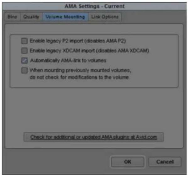
-
Click the Volume Mounting tab.
-
If you want the system to automatically scan drives (volumes) every time, select the option "When mounting previously mounted volumes, do not check for modifications to the volume." This option is off by default.
-
If you remount a volume, deselect the option "When mounting previously mounted volumes, do not check for modifications to the volume," and the system checks the modification date of the device or drive against the last time the clips were linked. If the date is the same, the clips come back online. If the date is different, the system links the clips again, and links any new clips added to the volume. This option is off by default.

If you restart your Avid editing application, the system automatically rescans the drives regardless of the options you've selected.
- To customize your bin, click the Bins tab.
By default, the system links your clips into a new bin using the same name as your project name. If you want to change the bin name or want to use an already existing bin, you can make these changes in the Bins tab.
For more information on Bins options, see "AMA Settings: Bins Tab" on page 1351.

Depending on your AMA Settings, every time you insert a card into a reader, the system creates a new bin whether the same card or device has been previously inserted or not.
- To map source audio channels to multichannel or mono tracks in your clips, click the Link Options tab, and then click Edit.
The Set Multichannel Audio dialog box opens. For information on setting multichannel audio options, see “Using XDCAM Multiple Resolution Clips with AMA” on page 400.
- Click OK.
Copying File-Based Media to a FireWire or Network Drive
After you insert cards or a disk into your third-party device, you can copy the media to a FireWire drive or a network drive and then eject the card or disk. You might find it convenient to copy several cards or disks to other drives so you can reuse the cards or disks.
You can also create Dynamic Media Folders (DMF) to copy all files placed in the DMF to a specified location. See “Creating Dynamic Media Folders” on page 381.

You can work with media on a card/disk or work with media on another drive, but you cannot work with media that is stored in both places simultaneously. To avoid the problem, eject the card or disk after you copy the media files to the other drive.
To copy the card or disk media to another drive:
- On the local or shared system drive, set up a folder for each card or disk you want to copy.
Avid recommends that you do not place the media folder at the top level of the drive. - Give each folder a unique name that identifies the card or disk.
The name does not have to be the same as the actual card or disk name. - Navigate to the actual card or disk and select the folder with the media.
- Do one of the following:
▶ Copy and paste the contents of the card or disk media folder to the system folder.
▶Click the card or disk folder and drag it to the system folder.
- Eject the card or disk.
Dragging and Dropping File-based Media Directly to a Bin
You can drag and drop file-based media directly to a bin.
To drag and drop files directly into a bin:
- Navigate to the folder that contains the file based media.
-
Select the files you want to drag to the bin.
-
Alt + drag (Windows) or Option + drag (Macintosh) the files to the bin.
The files appear in the bin as AMA linked files. These are also managed files and appear in the Media Tool.
Creating Dynamic Media Folders
Dynamic Media Folders (DMF) are user created folders that allow you to efficiently work with file-based media. DMF folders allow you to manage and process media even when the editing application is not running. For example, you can create a DMF folder where the media from a digital camera can be moved off the camera and placed in the DMF, allowing the production team to quickly take the camera back out in the field. A profile associated with that DMF folder can be setup to have these files AMA link into a particular bin.

AMA media is now managed. Therefore the AMA media will now appear in the Media Tool and can be checked into Interplay.
You can also create DMF folders that are setup to perform time consuming tasks such as copying, transcoding or consolidating. You can create a DMF folder that copies all files placed in the DMF to a specified location. You can also setup a DMF to transcode or consolidate any file that is placed in the folder to a specified resolution. These processes occur in the background.
The basic workflow for using DMF folders is the following.
- Create a folder. This folder can sit on your desktop or anywhere on your Avid editing system.
- Assign a profile to the folder. This profile is where you specify the actions you want performed on the files. Any time files are added to that folder, the actions you set in the profile for that folder will be applied to those files.
- An indicator on the Timeline will let you know when files have been added to a DMF folder. Access the DMF window and choose to place the files from the DMF folder into the appropriate bin.
To create a Dynamic Media Folder:
- Select Tools > Dynamic Media Folders. The Dynamic Media Folders window opens.

- Create a new folder by clicking the + icon in the Dynamic Media Folders window.
The Select Folder window opens. - Browse to the folder you want to designate as a Dynamic Media Folder.
- Click Select Folder.
- Click the Profile Editor button to create a profile that you want associated with the DMF folder.
The Profile Editor opens.

- Click the Menu bars to open the default profile summary and default AMA Settings and Actions.

- Select AMA Settings options as described in the following table.
Setting Option Description
AMA Plugin Link Using Select which Plug-in you want
the editing application to use when performing AMA links for the files added to the selected DMF folder. If you are linking to Volumes, Avid recommends you select the Autodetect AMA Plug-in.
Bins Use active bin When this option is selected,
your Avid editing application uses the currently active bin to store clips linked using AMA.
Setting Option Description
| Create a new bin When this option is selected,your Avid editing application creates a new bin to store clips linked using AMA and controls the bin name. This is the default option.Default bin naming convention: uses the project name for the bin (bin name followed by a consecutive number).Volume name: the name or label of the volume (for example D):Specify bin name: lets you enter a new bin name. | |
| Link Multichannel Audio Select this option if you want | to assign audio tracks to specific channels in your linked media, up to a maximum of 16 audio channels for the clips in your bins. This allows you to specify which source channels are treated as mono or multichannel audio tracks in your project, rather than having to modify the clips in your bin after you link to the AMA media.Click Edit to open the Multiple Mixes dialog box, which allows you to map audio tracks to channels. |
| Audio Start-Time Option (for Broadcast Wave) | Select this option to set the audio Project Rate for Broadcast Wave files. |
- To add additional actions to be performed on files found in the DMF folder such as copy, transcode, consolidate or check into Interplay, click the Actions + to add an action.

- Click the Menu button on a row to access the desired copying, consolidating and/or transcoding actions you want to be performed on the files. Choose from the following options:
Action Option Description
Copy to Folder Copy to: Click the Set button to choose
the location where you want the files copied to.
Auto Relink when complete Files are automatically relinked when the copy is completed.
Checkin to Interplay Checks in assets to Interplay.
When you select this option, also select the "Auto Relink when complete" option.
Consolidate Skip media files already on the target drive
Select to bypass files if some related media files are already located on the target drive.
Relink selected clips to target drive before skipping
Select to ensure that all selected clips are linked to media on the target drive.
Convert Audio Sample Rate Select this option to convert the sample rate to 32 kHz, 44.1kHz, or 48 kHz.
Convert Audio Bit Depth Select this option to convert the Bit Depth to 16 Bit or 24 Bit.
Action Option Description
| Convert Audio Format Select either OMF (WAVE),OMF(AIFF-C), or MXF(PCM) audio format. | |
| Video DriveAudio DriveSelect the applicable drives. | |
| Transcode Transcode Video Resolution Select the applicable Project | |
| Apply color transformations Transcodes the media with anycolor transformations (colorspace, LUTs, CDLs) that havebeen applied to the masterclips. | |
Action Option Description
| Video DriveAudio Drive | Select the applicable drives. |
- You can also reorder the actions by priority by dragging one above or below the other.
- Click Save to save the Profile.
- Name the Profile and click OK.
- Select Enable in the Dynamic Media Folders window to make sure that any files added to the Dynamic Media folder will have the actions set by the associated Profile.

Once a Profile is associated with a folder, you cannot change that Profile. You can only assign one Profile per folder.
When files are placed in a Dynamic Media Folder, you will see a progress indicator in the Timeline. If the Show Dynamic Media Folders progress indicator is green, new clips are available.

- Right+click the Show Dynamic Media Folders progress indicator and select Dynamic Media Folders.
The Dynamic Media Folders window opens.
- Click Acquire.
The new assets will populate the editing application Bin according to the Bin setting you chose in the Profile Editor. Any clips that have been consolidated or transcoded will also populate the bin as .new files. If some clips are still in process, they will populate the bin as offline. You can monitor the background progress of these files by selecting Tools > Background Queue.
Linking Media with AMA
The editing application will automatically link clips on a volume when you connect to your third-party device. You can also use the File > AMA Link option to manually link to a volume or file.
AMA media is managed. AMA managed media means that the AMA media is tracked. The AMA media is associated with .pmr and .mdb files. Therefore the AMA media will appear in the Media Tool and can be checked into Interplay.
AMA linking lets you point to media on a device or point to the media directly on your system. The media physically resides on your system or it can reside on an external device. The media points to the most recent source. For example, if you link the clips to a virtual volume on your desktop, the drive column displays the desktop as the location where the clips are linked to. If you then insert a card into a reader with the same media, the clips point to the media on the card. If you remove the card, the clips point to the media on the card and the clips appear offline. The card being the most recent source. Once the card is reinserted, the clips in the bin appear online. See also, “Using Virtual Volumes” on page 396 and “Virtual Volumes and AMA Bins” on page 397.

For optimum viewing and playing, Avid recommends a single clip length should not exceed more than 12 hours.

The decompose option from the Clip menu is not available with AMA. You do not need to decompose clips when you use the AMA Link.
To automatically link clips from a third-party device:
- Connect the drive, card reader or device to your computer as described in the third-party device documentation.
The system scans the device and links the clips into the default bin and with the default multichannel audio track formats (based on the AMA settings). A link icon appears next to the clip.
To change the default bin, bin name, or audio track format, from the Project window double-click AMA Settings and select options from the Bins and Link Options tabs. For more information, see “AMA Settings” on page 1351 and “Using XDCAM Multiple Resolution Clips with AMA” on page 400.
To link clips from a virtual volume with AMA:
- Select File > AMA Link.
The Open dialog box opens.

- Navigate to the folder that contains your file-based media.
For P2, navigate one level above the Contents folder. For XDCAM disks, navigate to one level above the Clip folder. For XDCAM EX, navigate to one level above the BPAV folder. For RED, navigate to the root directory of the RED card. For GFCAM, navigate to the root directory of the GFPAK. For QuickTime, navigate to the QuickTime folder that holds the QuickTime files.
Depending if you are using an existing bin or creating a new bin, the Bin Selection dialog box opens.

- Select Bin Selection options.
Option Description
Single Bin Based On Selected Folder Places all linked clips into one default bin.
Single Bin Named Lets you create a new bin and type in a new bin name.
Places all linked clips into that bin.
Bin(s) Based on Current AMA Setting
Places the clips in the bin(s) you set up in the AMA Settings Bins tab.
Bin(s) Based on Subfolders Places the clips in bin(s) based on their subfolders.
Top Bin Window Places the clips in the active bin.
- Click OK.
The clips appear in the bin or bins depending on the options you selected. A link icon appears next to the clips.
To link clips from a file with AMA:
- Select File > AMA Link.
You can also right-click a bin and select AMA Link.
-
The Open dialog box opens.
-
Navigate to and select the files you want to link to. Ctrl+click or Shift+click to select multiple files.
-
From the Files of Type menu either select Autodetect AMA Plug-in or select the plug-in from the list. Audodetect will detect the appropriate plug-in from the list of installed plug-ins.
5. Click Open.
The clips appear in the active bin with the default multichannel audio track formats (based on the AMA settings). A link icon appears next to the clips.
If the system cannot link a file, an error message displays informing you to open the Console window for more information about the file(s) in error.
If you move the clip from the original drive to another drive on your system, the clip displays as offline in your bin.

If you move a source file from one location to another and then back to the original location, you might need to refresh the bin to redisplay the clip. Close and reopen the bin to refresh the bin.
Relinking to AMA-Linked QuickTime Files
After you link Quicktime files into your sequence, you have the option to make changes (in a third party applications, such as Adobe After Effects) to that file. If you change the filename or change the location of the file, the best way to link that clip back into your sequence is through the relink option. Relinking to an AMA file allows you to link to a different file. This process only works if the targeted file is compatible with the old file, for example the file has the same duration, edit rate or number of tracks.
This feature is helpful when you have a group of linked clips that were moved to a different folder or drive. You can relink the clips to the new location. You can also use this feature to toggle between different versions of a QuickTime movie, for example a low-resolution version of the movie is myMovie_DV.mov and the high-resolution version of the movie is myMovie_1to1.mov. You can relink to both of these versions, to see which clip works better in your sequence.
At this time, Relink to AMA File(s) is only available with AMA QuickTime files.
To relink to AMA file(s):
- Select the file(s) you want to relink by doing one of the following:
▶Click a single file
▶Shift+click to select multiple adjacent files
▶Ctrl+click (Windows) or Command+click (Macintosh) to select multiple nonadjacent files
- Right-click and select Relink to AMA File(s).
The Select file(s) to relink AMA clip dialog box opens asking you to locate the new file(s).
- Locate the folder where the files exist.
- Click OK.
The clips appear linked in the bin. If all the clips you wanted to relink to do not reside in the selected folder, you will receive a dialog indicating how many files were not relinked. Open the Console window to see the name of the file or files that were not relinked.

If the new file is not compatible with the clip in the bin (it does not have the same duration, edit rate or number of tracks), the clip in the bin retains its original link.
Spanned Clips
Spanned clips are clips that extend from one card to another. Avid supports working with spanned clips with some third party devices such as P2, AVCHD, Canon, and XDCAM EX.
The following illustration shows how clips can span multiple cards.
natural_image
Abstract geometric pattern of gray rectangles stacked vertically within a larger rectangular frame (no text or symbols)Example of spanned clips. The white rectangles represent P2 cards and the gray rectangles represent clips. The first and third clips span multiple cards.
When you work with spanned clips, consider the following:
- If you remove a card that contains a spanned clip, for example Card 2 in the above example, and you try to play Clip 1, it plays until it reaches the portion of the clip that resides on Card 2. Media Offline appears until you reach the media on Card 3. Avid recommends that you do not place another card in the removed card's place unless you remove all the cards that contain the spanned clip (Cards 1 and 3 in this example).
- You can mix cards that contain spanned and unspanned master clips. However, if you eject a card which contains a chunk of a spanned clip and insert another card, the master clips in the newly inserted card are not visible in the Media Tool but the media files are visible. To work around this, remove all the cards which contain chunks of the spanned clip and choose File > Unmount followed by File > Mount All (non-AMA method). All the master clips are visible.
- P2 and XDCAM EX spanned media covers multiple drives, but the bin displays only one drive letter. The drive letter in the bin might be any of the drives, but is usually the highest lettered drive where the media exists.
- If necessary, copy all spanned clips to another drive to ensure a clip's integrity before you swap out the cards.
AMA Linking with Ancillary Data
You can AMA link to an XDCAM or an MXF (SMPTE 436M) clip with ancillary data, the ancillary data appears in your bin. You can link to the ancillary data clip without an Avid input/output hardware, however, in order to view the ancillary data in a monitor, an Avid Nitris DX or Avid Mojo DX device is required.
For information about ancillary data and data tracks, see “Preserving HD Closed Captioning and Ancillary Data” on page 1091 and “Data Track Method” on page 1092.
AMA Linking with Multichannel Audio
You can use the AMA Settings dialog box to define the audio track formats for the audio channels in your linked media, up to a maximum of 16 audio channels for the clips in your bins. This allows you to specify which source channels are treated as mono or multichannel audio tracks in your project, rather than having to modify the clips in your bin after you link to the AMA media.
The mappings affect all media clips created when you link to your source media. If you want to use different mixes for different master clips or different projects, create a custom AMA Settings template for each separate type of mix and then create your linked master clips.
Each stereo track requires two channels, but you can mix mono and stereo input channels for your linking operation as long as you do not exceed the maximum of 16 audio channels for each master clip.
To specify the multichannel audio mix for linked AMA clips:
- In the Project window, click the Settings tab.
- Double-click AMA.
The AMA Settings dialog box appears.
For information about the AMA Settings, see "AMA Settings" on page 1351.
- Click the Link Options tab.
The Link Options tab lists any multichannel audio mappings in the current AMA Settings template.

- Click Edit.
The Set Multichannel Audio dialog box opens.

- Click the format buttons to select one of the following audio track formats for each pair of source channels:

You must map source audio channels in mono or stereo pairs. For example, you cannot map A1 to a mono track and A2 and A3 to a stereo track. Instead, map A1 and A2 to mono tracks, and A3 and A4 to a stereo track. If the source media does not have an audio channel on A2, the Avid editing application ignores the channel.
- Click OK to close the Set Multichannel Audio dialog box, and then click OK to close the AMA Settings dialog box.
The Track Formats column in the bin Text view displays the format for all multichannel audio tracks in a master clip.
To save a custom map of linked audio channels as a settings template:
- Click the Settings tab in the Project window.
The Settings list appears.
-
Click AMA.
-
Select Edit > Duplicate.
A duplicate setting appears in the Settings list.
- Name the setting by doing the following:
a. Click the custom name column.
b. Type a name.
c. Press Enter (Windows) or Return (Macintosh).

The custom name column is the center column in the Project window. When you move the pointer over the custom name column, the pointer changes from a pointing finger to a text insertion bar.
You can select this new setting whenever you link clips with AMA.
The AMA Plug-in Log File
The Avid system creates an AMA plug-in log file when you link clips. The log file records errors and information about the clips. If you experience any problems while you link clips or if you receive an error message, check the AMA log file to get more information about the error (for example: a corrupt file or a bad filename). You can view the log file from the following location on your system:
- (Windows) drive:\Program Files\Avid Media Composer\Avid FatalError Reports. The name of the log file is AMALoggerMM_DD_YY.log.
- (Macintosh) Volume/Users/Shared/AvidMediaComposer/Avid FatalError Reports. The name of the log file is AMALoggerMM_DD_YY.log.
Using Virtual Volumes
You can use a virtual volume to copy media from a card or disk. This lets you use the card or disk again. A virtual volume can be a folder on your desktop or a folder located on a server. However, the virtual volume folder should reside one level down from the root level in order for the system to display it as a virtual volume. The following are examples of virtual volumes:
• C : \ D e s k t o p \ B P A V
• Z:\P2\Card 1
• Z:\GFPAK\
When linking to AMA volumes, the system looks into folders up to two levels deeper. This is helpful when linking to AMA volumes that contain left and right stereoscopic files/folders.
With the AMA method, all drives and virtual volumes associated with your bin mount automatically. You cannot remove a volume while in AMA, however you can remove a virtual volume.
To unmount a virtual volume:
The Unmount dialog box opens.
- Select the virtual volume you want to remove.
- Click OK.
The system removes the virtual volume from your system and clips linked to this virtual volume appear offline. When you restart your Avid editing application, the system scans the system for virtual volumes and the clips appear online.
Virtual Volumes and AMA Bins
If you select Volume Name in the AMA Bin Settings tab, the system names the bin the same name as the virtual volume drive name. If you continue to use the same virtual volume to link other media through AMA, the system continues to place the linked media in the same bin. If you want to create a new bin for different types of media you link through AMA, you can either create a new virtual volume drive for each type of media (XDCAM, XDCAM EX, P2, GFCAM, etc.) or you can create a new bin every time you link to new media on a virtual volume.
To create a new bin on the same virtual volume:
- Before you link your media through AMA, click the Settings tab in the Project window.
- Double-click AMA.
- Click the Bins tab.
- Select "Create a new bin" and specify a new bin name.
- Click OK.
- Select File > AMA Link.
The media appears in the newly created bin. Repeat these steps for each type of media.
Deleting Clips
You can delete master clips, but you cannot delete media files that reside on drives. Your Avid editing application treats files as read-only devices.
You can delete master clips and media files the same way you delete other master clips and media files. However, you might not be able to delete files that you moved rather than copied. If you cannot delete master clips and media files, first unlock the clips as described in the second procedure, and then delete them.
To delete files from cards/volumes:
- Quit your Avid editing application.
-
On the desktop, navigate to the drive.
-
Select the files you want to delete and press the Delete key.
To delete files on a local drive in your Avid editing application:
- In a bin, select the clips you want to delete.
- (Option) Right-click and select Unlock Bin Selection.
- Press the Delete key.
The Delete dialog box opens. - Select Delete master clips and Delete associated media files.
- Click OK.
You can also choose to AMA Link if you want to open the assets as Read-only in a classic bin.
Using AMA Plug-Ins
The following topics include high-level procedures of a typical workflow you might use when you edit with a particular media type and AMA Plug-Ins.
Using XDCAM and XDCAM EX and XDCAM SR AMA Plug-Ins
The Sony ^® XDCAM ^™ decks and camcorders use an optical disk to store recorded media. The XDCAM devices record media in high-resolution MPEG IMX ^™ , DVCAM ^™ , and XDCAM HD formats or corresponding low-resolution or compressed (proxy) media (MPEG-4). This lets you work with the compressed or low-resolution media in an off-line editing session and then later conform or link the compressed media to the corresponding high-resolution media. The HDCAM SR AMA plug-in supports MXF-wrapped SR Lite and SR SQ formats (422 YUV and 444 RGB) as transferred from HDCAM SR devices.
You can play XDCAM HD media to a Client monitor or output a digital cut as Best Performance (yellow/yellow) or Draft Quality (yellow/green). If you use Avid Nitris DX or Avid Mojo DX, you can play out the back of the HD-SDI.
The following steps describe a typical workflow for editing XDCAM, XDCAM EX or XDCAM SR clips with AMA.

Do not mix AMA and traditional workflows. Either use AMA when you work with an XDCAM device or use the traditional import/batch import workflow.
You should be aware of the following:
- Playback performance from an optical disk is very slow. To create a sequence with multiple effects or layered tracks, Avid suggests that you consolidate the media to a local drive, instead of working directly from the optical disk.
- Avid has turned off redrawing of waveforms in the Timeline when you link to XDCAM clips that reside on a disk. This allows for a faster linking process. When the media is consolidated, the waveforms redraw.
- When you link XDCAM clips from an optical disk, Avid recommends that you do not display the bin in Frame view or Script view due to performance issues.
A typical workflow is as follows:
- Make sure the Sony XDCAM and XDCAM EX, or XDCAM SR AMA plug-in is installed on your system.
- For XDCAM, install the appropriate Sony XDCAM drivers.
You do not need drivers for XDCAM EX. - Insert the XDCAM disk or XDCAM EX card.
The system links the XDCAM clips into a bin. The media itself remains on the disk. The clips point directly to the high-resolution media on the disk.
For XDCAM clips from an optical disk, a progress bar appears to show you how much time is left to link the media.

If you use multiple cards and you remove one of the cards, your media displays offline.
- Use the master clips to edit the sequence.
- (Option) Rename the clips to help organize your material.
- You can either transfer your media to your hard drive and then transcode or consolidate your sequence or clips, or consolidate directly from the XDCAM disk.

When you consolidate, if you want to keep your AMA clips linked to the original source, select the option “Keep Master clips linked to media on the original drive,” in the Copying Media Files dialog box.
Consolidating your media helps when you work with multiple cards. If you remove a card from the reader, consolidating lets you view your sequence with all the media online.
Due to the design of the Nitris input/output hardware, playback of XDCAM or XDCAM EX media on an Avid Symphony using Nitris causes dropped frames. To allow for full performance playback, transcode the XDCAM media into DNxHD media to play the video on your Avid Symphony system with Avid Nitris input/output hardware.

For information on consolidating your sequence, see “Consolidating Media” on page 449. For information on transcoding your sequence, see “Using the Transcode Command” on page 455.
- Remove the XDCAM disk or XDCAM EX card:
(Windows) Select Safely Remove Hardware icon in the taskbar and select Safely Remove XDCAM EX device name.
▶(Macintosh) Click the device icon on your desktop and drag it to the Trash.
Using XDCAM Multiple Resolution Clips with AMA
The XDCAM AMA plug-in allows you to link to low-resolution (proxy) or high-resolution audio or video media. The AMA multiple resolution feature supports specific XDCAM devices which include a /PROAV folder. For example, the Sony PDWU1 Professional Disc Drive Unit. See your Sony documentation for information on how to enable the /PROAV directory for your device.
Avid editing systems do not support XDCAM proxy audio.
The following steps describe a typical workflow for editing XDCAM multiple resolution clips with AMA.

Do not mix AMA and traditional workflows. Either use AMA when you work with an XDCAM device or use the traditional import/batch import workflow.
You should be aware of the following:
- Playback performance from an optical disk is very slow. To create a sequence with multiple effects or layered tracks, Avid suggests that you consolidate the media to a local drive, instead of working directly from the optical disk.
- Avid has turned off redrawing of waveforms in the Timeline when you link to XDCAM clips that reside on a disk. This allows for a faster linking process. When the media is consolidated, the waveforms redraw.
- When you link XDCAM clips from an optical disk, Avid recommends that you do not display the bin in Frame view or Script view due to performance issues.
A typical workflow is as follows:
- Use Sony's PDZ-1 software to associate your low-resolution clips with metadata to identify the clip in the Avid bin. This includes entering a User Disc ID in the Disc Properties window.
- The Sony XDCAM and XDCAM EX AMA plug-in should be installed on your system.
- Install the appropriate Sony XDCAM drivers.
-
In the Project window, click the Settings tab.
-
Double-click AMA.
The AMA Settings dialog box appears. - Click the Quality tab.
- Click the appropriate resolution for your video and audio in the AMA Link Preference section, and click OK.
- Insert the XDCAM disk in the XDCAM device.
- Select Bin Selection options from the Bins tab.
For information on bin selection options, see “Linking Media with AMA” on page 388.
- Select File > Link to AMA Volume.
The Browse for Folder dialog box opens.
- Navigate to the XDCAM clips, and then click OK.
The clips appear in the bin or bins depending on the bin options you selected. A link icon appears next to the clips.
-
Edit the sequence.
-
Right-click the bin and select Modify AMA Resolutions to relink your low-resolution to high-resolution media.
-
To consolidate your media, see “Consolidating Multiple Resolution Media” on page 402.

When you consolidate, if you want to keep your AMA clips linked to the original source, select the option “Keep Master clips linked to media on the original drive,” in the Copying Media Files dialog box.
- Click the Highest Quality for your video and audio and click OK.
The highest quality clips appear in the bin along with the low resolution (most compressed) clips. A link icon appears next to the clips.
If the system cannot find the corresponding low-resolution clip, it might be because you inserted the wrong XDCAM disk. If you insert the wrong disk, the system displays a message that informs you to insert the correct disk. If you used Sony's PDZ-1 software and provided a disk name in the User Disc ID field, the system message displays the disk label name. If you did not use the PDZ-1 software, the system asks you to insert the disk containing the (low-resolution) clip selected in the bin.
- Remove the XDCAM disk.
Spanned clips are clips that extend from one card to another. Avid supports working with spanned XDCAM EX clips in your Avid editing application.
For more information about spanned clips, see “Spanned Clips” on page 392.
Switching Between Multiple Resolution Media
Once you link to the low-resolution or high-resolution media and complete your edits, you can easily switch from low to high and high to low-resolution media. When you switch to a different resolution, the system replaces the clip in the bin with the new clip and resolution.
The steps below highlight switching from low-resolution to high-resolution media. You can also switch from high-resolution to low-resolution.

For XDCAM, if you use the Sony PDZ-1 software to assign a User Disc ID, the Avid editing system displays this information in a bin column and knows what disk name is associated with each clip.
To switch from low-resolution to high-resolution media:
- Insert the disk in the device.
- Select the low-resolution clips in the bin.
- Right-click the bin and select Modify AMA Resolutions.
The AMA Resolutions Quality dialog box appears.

- Click the Highest Quality for your video (audio is always set to Highest Quality) and click OK.
The highest quality clips replace the most compressed (low-resolution) clips in the bin. A link icon appears next to the clips.
If the bin contains clips from multiple volumes, you will be prompted to insert another disk.
Consolidating Multiple Resolution Media
When you are ready to move your media to shared storage, you can link to your resolution and consolidate at the same time.
The steps below highlight consolidating high-resolution media. You can also consolidate low-resolution media.
For information on why you should consolidate, see “Consolidating Media” on page 449.
To consolidate high-resolution media:
- In the Project window, click the Settings tab.
- Double-click AMA.
The AMA Settings dialog box appears.
For information about the AMA Settings, see "AMA Settings" on page 1351.
- Click the Quality tab.
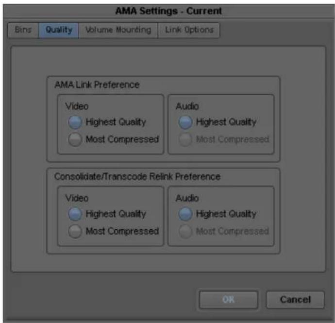
- Click the appropriate resolution for your video in the Consolidate Preference section, and click OK.
If a particular resolution is not available, it will be grayed out.
- To consolidate the clip, follow the steps in "Using the Consolidate Command" on page 451.
The resolutions you select in the Consolidate Preference area of the AMA Settings Quality tab displays in the Transcode/Consolidate dialog box when you consolidate or transcode.
Using the P2 AMA Plug-In
Panasonic's P2 equipment records DV, DVCPRO, and DVCPRO 50 media on compact, solid-state memory cards (P2 cards). Avid editing applications support editing of media directly from these memory cards, without the need to capture. You can also write your sequence back to the P2 card. Panasonic P2 video and audio media is recorded in MXF format.
The following are recognized as P2 cards by your Avid editing application:
- Panasonic P2 cards in an attached reader or camera or in a laptop PC Card slot.
- Synthetic P2 cards. A complete copy of a P2 card copied to the root of a drive or mounted as a drive, for example, by mapping to a drive letter.
Each P2 card stores MXF files in two folders:
• ( W i n d o w s ) drive:\Contents\Audio
(Macintosh) Macintosh HD/Contents/Audio
• ( W i n d o w s ) drive:\Contents\Video
(Macintosh) Macintosh HD/Contents/Video
| Name | Size | Type |
| 0014KG00.mxf | 834 KB | MXF File |
| 0014KG01.mxf | 834 KB | MXF File |
| 0015ZQ00.mxf | 1,031 KB | MXF File |
| 0015ZQ01.mxf | 1,031 KB | MXF File |
| 0018CY00.mxf | 764 KB | MXF File |
| 0018CY01.mxf | 764 KB | MXF File |
| 0019DK00.mxf | 584 KB | MXF File |
| 0019DK01.mxf | 584 KB | MXF File |
| 0019DK02.mxf | 584 KB | MXF File |
| 0019DK03.mxf | 584 KB | MXF File |
| 0013SF00.mxf | 1,112 KB | MXF File |
| 0013SF01.mxf | 1,112 KB | MXF File |
| 00179X00.mxf | 899 KB | MXF File |
| 00179X01.mxf | 899 KB | MXF File |
| Name | Size | Type |
| 00179X.mxf | 32,517 KB | MXF File |
| 00135F.mxf | 40,462 KB | MXF File |
| 0019DK.mxf | 41,376 KB | MXF File |
| 0018CY.mxf | 27,455 KB | MXF File |
| 0015ZQ.mxf | 74,798 KB | MXF File |
| 0014KG.mxf | 30,033 KB | MXF File |
Examples of MXF audio and video files contained in the Audio and Video folders. Top: four audio tracks for a single clip. Bottom: the corresponding video track.
Panasonic P2 devices write individual MXF audio and video media files for each track of each clip. For example, a P2 clip that includes one track of video and four tracks of audio is stored on the P2 card as five individual media files. Within your Avid editing application the five media files are represented as a single clip with audio and video.
The following steps describe a typical workflow for editing P2 clips with AMA.

Do not mix AMA and traditional workflows. Either use AMA when you work with a P2 device or use the traditional import/batch import workflow.
A typical workflow is as follows:
- Make sure the Panasonic P2 AMA plug-in is installed on your system.
- Install the appropriate Panasonic P2 driver.
- Mount one or more P2 cards (up to five). For information on mounting and naming P2 cards, see your Panasonic device documentation.
The system links the P2 clips automatically into a bin.

If you use multiple P2 cards and you remove one of the cards, your media displays offline.
- Use the master clips to edit and output a sequence.
- (Option) Rename the clips to organize your material.
- Consolidate or transcode your sequence or clips.
The media consolidates to the destination you set in the Media Creation dialog box.
Consolidating your media helps when you work with multiple P2 cards. If a card is removed from the reader, consolidating lets you view your sequence with all the media online.

When you consolidate, if you want to keep your AMA clips linked to the original source, select the option “Keep Master clips linked to media on the original drive,” in the Copying Media Files dialog box.

When you transcode a sequence, the system automatically defaults to convert both audio and video. You cannot transcode video only with P2.

For information on consolidating your sequence, see “Consolidating Media” on page 449. For information on transcoding your sequence, see “Using the Transcode Command” on page 455.
- Remove the P2 card.
If you work in an Avid shared storage environment, you can share sequences that contain P2 clips in an Avid shared storage workspace. However, you can share P2 clips only if you transcode or consolidate them to a workspace.
- In an MXF workgroup, you can either consolidate or transcode P2 clips to a workspace. If you transcode, you must transcode P2 MXF files to another MXF resolution.
- In an OMF workgroup, you must transcode P2 clips to a workspace. You must transcode P2 MXF files to OMF files.
If you consolidate or transcode clips to an Avid shared storage workspace, it automatically checks all related metadata into the asset manager. This makes the clips accessible to other users.
For more information on workgroup support, see the Avid Interplay Help.

Some card slots of the P2 drive might require drive letters that have already been assigned to existing network drives. If your computer does not display all five card slots as drives, reassign the network drives or restart your system.
Spanned clips are clips that extend from one card to another. Avid supports working with spanned P2 clips in your Avid editing application.
For more information about spanned clips, see “Spanned Clips” on page 392.
Using the AVCHD AMA Plug-In
AVCHD is a file-based format and does not use magnetic tape. Instead, video can be recorded onto DVD discs, hard disk drives, non-removable solid-state memory and removable flash memory cards.

Play performance might vary depending on the type of medium you use and the speed of our computer.
AVCHD media files are recorded in MTS format; the file contains both the video and audio. Audio can be either uncompressed PCM or Dolby ^® AC-3 format.

You must activate the Dolby AC-3 codec the first time you AMA link to an AVCHD clip. If you are connected to the Internet, activation is automatic. If you are not connected to the Internet, the system opens a dialog box and then the Avid License Control tool. Follow the on screen instructions to activate this feature.
The folder and file structure is dependent on the camera you use.

Most AVCHD cameras produce default file names starting with “00000.” Be aware that you could have multiple clips with the same file name across multiple media drives.
The following steps describe a typical workflow for editing AVCHD clips with AMA.
A typical workflow is as follows:
- Install the AVCHD AMA plug-in on your system.
- To link to an entire volume, attach the camera and insert a card, disc or drive.
The system links the AVCHD clips automatically into a bin.

It is highly recommended for performance reasons, that you copy the entire media volume to an external HD drive if you plan on copying media from a card. You may have to use the File > AMA Link command if the files do not automatically link.

If you use multiple AVCHD cards and you remove one of the cards, your media displays offline.
-
To link to an individual AVCHD file, with the camera and card, disc or drive inserted, select File > AMA Link.
The Open dialog box opens. -
From the AMA Plugin Filter menu, select AVCHD.
-
Locate and select the .mts file(s) you want to link. Ctrl+click or Shift+click to select multiple files.
-
Click Open.
The clips appear in the active bin. A link icon appears next to the clips.
- Use the master clips to edit and output a sequence.
- (Option) Rename the clips to organize your material.
- Transcode your sequence or clips.

When you transcode a sequence, the system automatically defaults to convert both audio and video. You cannot transcode video only with AVCHD.

For information on transcoding your sequence, see “Using the Transcode Command” on page 455.
Spanned clips are clips that extend from one card, disc or drive to another. Avid supports working with spanned AVCHD clips in your Avid editing application.
For more information about spanned clips, see “Spanned Clips” on page 392.
Using the Canon XF AMA Plug-In
The Canon XF305 and Canon XF300 camera records MPEG-2 media onto compact flash cards. Through the Canon XF AMA plug-in and the MXF AMA plug-in, you can link to Canon MPEG-2 media through the AMA method. Canon XF video and audio media files record in MXF format.
You can edit directly from a flash card, without having to capture. You can link to a Canon XF flash card and reader attached to your system or copy a Canon XF flash card to the root of a drive.
Each card stores the video and audio files in:
- ( W i n d o w s ) d r i v e : \ C O N T E N
• (Macintosh) Macintosh HD/CONTENTS/CLIPS

AMA does not recognize clips if the folder names in the selected path contain double-byte characters (DBCS). AMA recognizes folders with the directory path that includes ASCII alphanumeric characters.
A typical workflow is as follows:
- The Canon XF AMA plug-in and the MXF AMA plug-in should be installed on your system.
- Mount the flash cards.
The system links the Canon XF clips automatically into a bin.

If you use multiple flash cards and you remove one of the cards, your media displays offline.
- Use the master clips to edit and output a sequence.
- (Option) Rename the clips to organize your material.
- Consolidate or transcode your sequence or clips.
The media consolidates to the destination you set in the Media Creation dialog box.
Consolidating your media helps when you work with multiple cards. If a card is removed from the reader, consolidating lets you view your sequence with all the media online.

When you consolidate, if you want to keep your AMA clips linked to the original source, select the option “Keep Master clips linked to media on the original drive,” in the Copying Media Files dialog box.

For information on consolidating your sequence, see “Consolidating Media” on page 449. For information on transcoding your sequence, see “Using the Transcode Command” on page 455.
- Remove the flash card.
Spanned clips are clips that extend from one card to another. Avid supports working with spanned Canon XF clips in your Avid editing application. For more information about spanned clips, see “Spanned Clips” on page 392.
Using the GFCAM AMA Plug-In
The Ikegami GFCAM HDS-V10 is a tapeless camera/recorder that uses flash memory instead of video tapes as a recording medium. GFCAM devices record MPEG-2 Long GOPmedia onto a GFPAK ^™ , a removable high-speed storage medium. GFCAM is only available through the AMA method. GFCAM video and audio media files record in MXF format.
Each GFPAK stores the video MXF files in:
• (Windows) drive:\BINxxx\VIDEO
• (Macintosh) Macintosh HD/BINxxx/VIDEO
Each GFPAK stores the audio MXF files in:
• (Windows) drive:\BINxxx\AUDIO
• (Macintosh) Macintosh HD/BINxxx/AUDIO
The GFCAM video file directory stores MXF files regulated by SMPTE 390M (MXF OP-Atom) and SMPTE 381M (MXF mapping MPEG streams into MXF GC). If a video clip needs to split, such as under the FAT32 file system, the system creates multiple MXF files for that clip.
The GFCAM audio file directory stores MXF files regulated by SMPTE 382 (MXF mapping AES3 and BWF into the MXF GC). Each file has an AES channel that consists of two audio channels. For example, the system creates two MXF files from two AES channels (four audio channels). If an audio clip splits, the system creates multiple audio files for that clip.
GFCAM allows gapless recording over several GFPAKs, however, each GFPAK handles the contents as a separate clip. If you record across three GFPAKs, you create three separate clips. You can then edit those clips together into one continuous sequence.

1080p/23.98 pulldown and 720p/23.98 pulldown record at 59.94fps and are only compatible with 1080i/59.94 and 720p/59.94 projects.
1080p/29.97 records as PSF at 59.94fps and is only compatible with 1080i/59.94 projects.
1080p/25 and 720p/25 record as PSF at 50fps and are only compatible with 1080i/50 and 720p/50 projects.
A typical workflow is as follows:
- Make sure the GFCAM AMA plug-in is installed on your system.
- Insert the GFPAK.
Your Avid editing system links the GFCAM clips automatically into a bin. The media itself remains on the disk. The clips point directly to the high-resolution media on the disk.

If you use multiple GFPAKs and you remove one of the GFPAKs, your media displays offline.
- Use the master clips to edit the sequence.
- (Option) Rename the clips to organize your material.
- Consolidate or transcode your sequence or clips.
Consolidating your media helps when you work with multiple GFPAKs. If a GFPAK is unplugged, consolidating lets you view your sequence with all the media online.

When you consolidate, if you want to keep your AMA clips linked to the original source, select the option “Keep Master clips linked to media on the original drive,” in the Copying Media Files dialog box.

When you transcode a sequence, the system automatically defaults to convert both audio and video. You cannot transcode video only with GFCAM.
- Disconnect the GFPAK.
Working with Shot Marks and Check Marks with GFCAM Media
GFCAM products use Shot Marks and Check Marks to store metadata about media clips.
Shot Marks allow GFCAM cameras to mark events such as clip start points or audio clipping. Press the RET button on the GFCAM device while you record or playback to set a Shot Mark. For a description of Shot Marks, see your GFCAM documentation.
In the AMA method, Shot Marks are brought over automatically and appear as markers in your Avid editing application. There is no text associated with a Shot Mark, just a marked location (or a marker). For information about editing markers, see “Using Markers” on page 523.
A Check Mark flags a “good shot.” The AMA method translates this good shot clip with the word “true” in a new bin column named Check Mark. If there are no Check Marks associated with a clip, a Check Mark heading does not appear.
Using the RED AMA Plug-In
The RED ONE camera generates a 4K (or 2K - 4.5K) full resolution REDCODE™ RAW (.R3D) file. Media is stored on a REDFlash card or a RED drive. You can link to a specific R3D file on the volume or link to the entire volume. RED ONE cameras record metadata which displays in an Avid bin. The metadata includes: edge code, timecode, lens parameters, audio settings and any video image processing information.
Your Avid editing application supports RED R3D files as high quality HD media. Once you link the clips through AMA, you can change and fine-tune the clip color settings through the Source Settings dialog.

You cannot consolidate the RED media in your Avid editing application.
The RED Camera records a unique clip name and additional files that include the REDCODE RAW files and an optional QuickTime reference file placed in a clip folder (.RDC). The system names clips by Camera Letter + Reel Number + Month + Day + a two digit alphanumeric random number.
For example: A001_C002_0502A6.RDC
Each clip folder (.RMD) is at the root directory. In each of these folders is the .RDC folder which contains the video, audio, and metadata files:
- (Windows) drive:\camera+reel_date.RMD\camera+reel_clip_date+random number.RDC
• (Macintosh) Macintosh HD/camera+reel_date.RMD/camera+reel_clip_date+random number.RDC
Avid's RED workflow allows you to work with RSX, RLX, and RMD files to manage a clip's color. You have access to all the metadata and color values in the raw RED files as well as the above mentioned "look" files associated with this media. You may also make non-destructive, custom color adjustments to the R3D clip. These adjustments can be made at any stage of the process.
AMA detects folders named with RMD and RDC and files named .R3D.

Audio is included in the RED files, and will display as .wav files in the bin.
You cannot span media across multiple cards. Each clip is recorded as a separate clip, regardless of how many cards you use. There is a 2GB limit on a single master clip. As you record footage, once a 2GB file is captured, an R3D file is created (.001). The camera continues to record and the next 2GB (or less) of media creates another R3D file (.002) until you end recording. So, you can have several R3D files in one clip folder but they are all associated with one master clip. When you link these files/folders through the AMA method, one master clip appears in your bin
A typical workflow is as follows:
- Make sure the RED AMA plug-in is installed on your system.
- Attach the RED drive or insert a REDFlash card.
Your Avid editing system links the RED clips automatically into a bin. The media itself remains on the disk. The clips point directly to the high-resolution media on the disk. All metadata information displays as columns in the bin.

If you use multiple cards and you remove one of the cards, your media displays offline.
- Right-clip the clip in the bin and select Source Settings.
For detailed information to set clip parameters, see “Adjusting RED Source Settings” on page 413. - Use the master clips to edit the sequence.
- (Option) Rename the clips to help you organize your material.
- Choose the video quality from the Transcode & Consolidate tab of the Media Creation setting.
For more information, see “Preparing your RED Clip for Transcode, Mixdown, or Render” on page 412. - Transcode your sequence or clips to an HD or SD resolution.
If you need to output to a resolution higher than HD, then export an AFE of your sequence for the conform process on an Avid DS. If your high-resolution media is on a shared storage device and Avid DS has access to the device, Avid DS automatically relinks to the RED files.
- Remove the RED drive or card.
For information on preparing your RED clip for transcode, mixdown, or renders, see “Preparing your RED Clip for Transcode, Mixdown, or Render” on page 412
Preparing your RED Clip for Transcode, Mixdown, or Render
If you want to take a RED clip and offline it to another application, you can create a different resolution RED file, depending on your requirements. This changes the speed and quality of the clip, which could affect the playback performance. The higher the video quality the slower the process (transcode, mixdown, render). The lower the video quality the faster the process. Before you transcode, mixdown or render your clip or sequence, set the appropriate quality in the Media Creation dialog box.

If you apply any Reformat options (stretch, letterbox, etc.) to your clip, when you perform a transcode, the reformatting options will apply.
To prepare your RED clip for transcoding, mixdown or rendering:
- Before you transcode, mixdown or render, select Tools > Media Creation.
- Click the Mixdown & Transcode tab or click the Render tab.
- Select the playback quality from the R3D Source Quality (Debayer) menu.
▶Full
▶Half (Best Quality)
▶Half (Good Quality)
▶Quarter
▶Eighth
▶Sixteenth
-
Click OK.
-
Transcode, mixdown or render your clip or sequence as required.
For information about transcoding, see “Using the Transcode Command” on page 455.
For information about mixdown, see “Performing a Video Mixdown” in the Help.
For information about render, see “Basics of Effects Rendering” in the Help.
Adjusting RED Source Settings
When you link to R3D (RED) files, the Avid editing system reads each REDCODE RAW file directly. You can then change the clip's color values: color balance, exposure, and contrast in the Source Settings window. This color value information is encoded with the R3D file through an RLX, RSX or RMD file. These files hold the camera's original color values of your clip.

The RLX, RSX or RMD files might be created if you set the color values outside of the Avid editing application. These files can be loaded and applied to the associated RED clip through the Source Settings window.
When a RED clip displays in the bin, the system displays the metadata columns of the clip's color values. For example: Color Space, Gamma Space, Kelvin, Tint. You can export this information to ALE (Avid Log Exchange) and XML (through Avid FilmScribe) for downstream use in your workflow.
The AMA Source Settings window also has various color spaces to choose from. You can set up different color options (or presets) in each of these color spaces and then apply their color values to multiple clips.
To change the RED source settings:
- Link the RED clip through the AMA Link option.
See “The Avid Media Access (AMA) Workflow” on page 374 and “Linking Media with AMA” on page 388 for information on linking.
- Right-click the RED clip in the bin and select Set Source Settings.
The Source Settings dialog box opens. The clip displays in the video area.
You can choose from the Settings menu to select a camera metadata setting or an RSX, RLX or RMD setting (template), or adjust your own custom parameters. This procedure details the custom parameters.
For information on settings (templates) in the Settings menu and how to apply a setting, see "Using RED Source Settings" on page 418 and "Applying a RED Source Setting" on page 418.
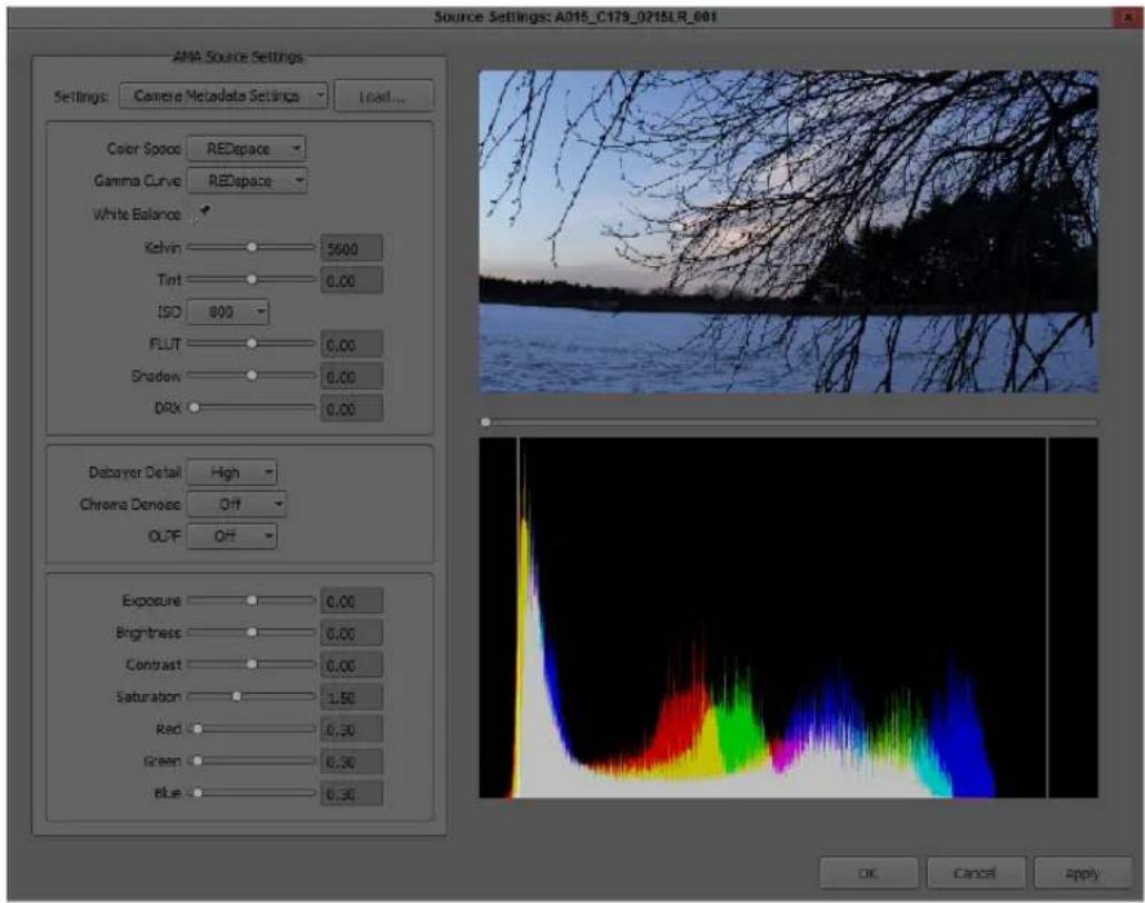
- Drag the video slider to the frame you want to view.
The new frame displays and the histogram updates.
The histogram is a tool that helps you more precisely adjust Source Settings. For more information about the histogram, see “Understanding the Source Settings Histogram” on page 428
- Set the appropriate options, you can select from a menu, drag the sliders, enter values or click the eyedropper:
Option Description
Color Space Choose from:
Camera RGB: as close to RAW
REC.709: SMPTE standard color space for HD
REDcolor (default): newest, more accurate color science from RED
REDcolor2: better skin tones and color from RED
REDcolor3: more improvements from RED
REDSpace: based on the camera's RGB but more saturated
Gamma Curve Lets you override the gamma curve. Choose from:
REC.709: a REC.709 gamma curve with a linear portion at black and a gamma at 2.2 curve
REDLog: maps the 12-bit sensor data on to a 10-bit curve with minimal loss
REDLogFilm: a way of containing a large dynamic range in a video file. Needs to be viewed through a LUT to convert it for viewing on a monitor.
REDSpace: based on REC.709 but with more contrast
REDGamma (default): gamma curve from RED with a smoother highlight rolloff
REDGamma2
REDGamma3
White Balance Adjusts the color temperature of your image in one click. Use the
eyedropper icon and then click a known white area in your RED footage to achieve the correct light or neutral balance. This option is equivalent to adjusting the Kelvin and Tint options. When you use the White Balance option, the system automatically adjusts Kelvin and Tint. It is recommended you adjust White Balance first before performing any other adjustments to the image for best quality. This change adjusts the entire clip and updates the histogram.
Kelvin Adjusts the RGB color to compensate for red - blue tinting of the
scene at different color temperatures of the ambient light while you shoot. Common values are 3200 (tungsten) and 5600 (daylight).
Click and drag the slider from 1700 to 9400. Default is 5600.
Option Description
| Tint Adjusts the RGB color to compensate for yellow - green tinting of the scene at different color temperatures of the ambient light while you shoot. This is valuable when the ambient light source contains a significant amount of yellow or green, such as fluorescent. Click and drag the slider from -100 to 100. Default is 0.00. | |
| ISO Allows the ISO level to change from 50 to 2000. Default is 320. | |
| FLUTTM | The latest color science developed by RED. Allows you to balance your mid-grays in the center of the histogram without pushing highlight details over the edge. |
| Shadow Adjusts the overall black level of the image without affecting the white level. Click and drag the slider from 0.00 to 1.00. Default is 0.00. | |
| DRX Lets you recover potentially lost dynamic range by extending and balancing highlights, taking into account the rendering intent of the desired Kelvin and Tint white balance. Click and drag the slider from 0.00 to 1.00. Default is 0.00. | |
| Debayer Detail Choose from High (default), Medium, or Low. | |
| Chroma Denoise Choose from Off (default), Minimum, Milder, Mild, Strong, or Maximum. | |
| OLPF Controls the optical low-pass filter. Choose from Off (default), Low, Medium, or High. | |
| Exposure Allows adjustment to the clip exposure. Click and drag the slider from -7.00 to 7.00. Default is 0.00. | |
| Brightness Adjusts the overall brightness of the image. Lifts blacks without affecting the white level. Click and drag the slider from -10.00 to 10.00. Default is 0.00. | |
| Contrast Adjusts the tonal range of the image, which usually improves sharpness and detail. When you increase the Contrast, it increases tonal separation between adjacent gray levels but decreases the total number of discreet gray levels in the image.Click and drag the slider from -1.00 to 1.00. Default is 0.00. | |
Option Description
Saturation Affects the intensity of the red, green and blue channels. As the value increases color saturation increases. As the value decreases, so does the color decrease. If the value is set to high, colors might clip. If the level is set to 0.00, a monochromatic image with only gray tones appear. Click and drag the slider from 0.00 to 4.00. Default is 1.00
Red Increases or decreases the camera's sensitivity to red light by amplifying the R channel digital video signal received from the sensor. A 0 (zero) no Red is visible, the image has a strong cyan cast. Click and drag the slider from 0.00 to 10.00. Default is 1.00.
Green Increases or decreases the camera's sensitivity to green light by amplifying the G channel digital video signal received from the sensor. At 0 (zero), no green is visible, the image has a strong magenta cast. Click and drag the slider from 0.00 to 10.00. Default is 1.00.
Blue Increases or decreases the camera's sensitivity to blue light by amplifying the B channel digital video signal received from the sensor. At 0 (zero), no blue light is visible, the image has a strong yellow cast. Click and drag the slider from 0.00 to 10.00. Default is 1.00.
5. Click Apply.
The changes apply to your clip. You can continue to make additional changes.
If the clip is in the Source viewer, the changes are reflected in the Source viewer and in the Client monitor (if you have one attached).
If you click Cancel after you click Apply, the Set Source Settings window closes with the changes you made.
6. Click OK to save your change and close the window.
The system updates the bin column metadata with the new parameters.

If you make changes in the Source Settings window and then relink the clip through AMA again, you still keep all the parameters that you set.
Using RED Source Settings
Source Settings lets you choose from a selection of preset templates or you can create your own look. Each source setting has its own color values associated with it. There are a few different ways to obtain source settings:
- Camera and default source settings are included with the RED AMA plugin
- Link a RED clip from RED Alert! (imports the RSX source setting)
- Load a source setting onto your system (for example, an RLX, RSX, or RMD)
- Create a custom source setting
You cannot change the default RSX and RLX source settings, these are predefined. Once you make a change to a parameter, the setting becomes a Custom setting. At this time, you can only have one Custom setting.
You can load multiple RSX and RLX source settings. As you link a RED clip from RED Alert! (RSX) or load an RLX file, the setting appears in the Source Settings menu.
Source Settings are helpful when you want to apply one setting to multiple clips in your bin.
Different subclips from the same master clip can have different source settings.
When you edit a clip into a sequence, the material you edit in uses the clip's current attribute values or RED source settings. If you change the RED source settings at a later point in your workflow, the sequence does not automatically adjust for the change. If you want the sequence to use the RED source settings for clips that you have changed since you edited, you must refresh the sequence. For procedures on how to refresh your sequence, see “Refreshing Sequences to Use Current Clip Attributes” on page 601.
Applying a RED Source Setting
To apply a source setting to a RED clip:
- Right-click a RED clip in the bin (or Shift-click multiple clips), then choose Set Source Settings.
The Set Source Settings window opens and your clip displays in the viewer.
- Select a setting (template) from the Source Settings menu.
Source Settings vary depending on the files or templates loaded on your system.
Setting Origin
Camera Metadata Settings Default
Setting Origin
Default Settings Default
Grade (RSX) Settings RED Alert!
filename RLX Setting RED Alert!
Grade (RMD) Setting REDCINE-X
Custom User created in Avid
3. Click Apply.
The settings apply to the clip and if the clip is loaded in the Timeline, the video updates and displays in a Client monitor (if one is attached) and the Source monitor.
4. Click OK to save your settings and close the window.
The system updates the bin column RED metadata with the parameters.
If you make additional changes after you select a setting, the system creates a Custom setting and Custom appears in the Settings list. You cannot make changes to a system generated setting, however you can use a system setting and make changes to create your own Custom setting.
To import additional source settings:
- From the Source Settings window, click the Load button.
The Load External Settings window opens.
- Browse to the Settings file.
- Change the filter to display RSX, RLX or RMD files.
- Select your setting and click OK.
The new source setting appears in the Source Settings menu, and is immediately applied to the clip.
Using the QuickTime AMA Plug-In
There are a few guidelines you should follow when you link QuickTime files through AMA.
To link QuickTime media through the AMA method, you first need to create a QuickTime movie from a third-party application or through the Avid editing system. The third-party applications that supports creating a QuickTime movie include Adobe AfterEffects® and Final Cut Pro. This is done through the QuickTime Export dialog box which uses the Avid QuickTime Codecs.
These codecs automatically install on your Avid editing system. At this time, Avid supports the
Same as Source and Custom export settings options when you export with the Avid QuickTime codecs. This process creates an Avid compressed QuickTime media file, with a .mov extension. AMA only detects and links to Avid compressed QuickTime media.

For information about exporting a QuickTime movie, see “Exporting QuickTime Movies” on page 1024.
QuickTime files use the .mov file name extension. After you link a QuickTime file through AMA, the file drops the .mov file name extension. QuickTime media is linked at the data rate at which it was recorded.
A QuickTime AMA workflow is as follows:
- Create a QuickTime movie with a supported codec in an application such as Adobe AfterEffects or Apple's Final Cut Pro.
Avid supports the Same as Source and Custom export settings options when you export with Avid QuickTime codec.

See Adobe and Apple documentation for information on how to create a QuickTime movie.
- Move the created .mov file onto your Avid editing system.
- Open a bin.
If there is no active bin, a dialog box appears asking you to select a bin.
- Select File > AMA Link.
You can also right-click a bin and select AMA Link.

To link to multiple QuickTime files, use the File > Link to AMA Volume(s) option and select the folder that stores all the QuickTime files.

For information about AMA, see “The Avid Media Access (AMA) Workflow” on page 374.
The Open dialog box opens.
- From the AMA Plugin Filter menu, select QuickTime.
- Locate and select the .mov file(s) you want to link. Ctrl+click or Shift+click to select multiple files.
- Click Open.
The clips appear in the active bin. A link icon appears next to the clips.
If any of the movies you linked to were QuickTime with Alpha channel files, they appear in your bin as a Matte Key effect. The Alpha Channel options in the Import Settings Image tab apply to the QuickTime AMA linked file. Therefore, the QuickTime file will appear in the bin as a master clip if the Ignore option is set or will appear inverted or not inverted depending on the selected options.
- Use the linked clips to edit your sequence.
- If you need to change the QuickTime clip in After Effects or FCP, open the existing file in After Effects or FCP and make the change.
If you change the number of tracks, change the duration of the clip or change the clips file name, when you relink through AMA, the system creates a new clip and will not overwrite or replace the existing clip in the bin.
If you change the number of tracks, the duration, or edit rate, but not the file name, any clips linked to the sequence will unlink and the clips display Media Offline.

If you change the file name or the location of the clip, you can Relink to AMA files. For more information, see “Relinking to AMA-Linked QuickTime Files” on page 391.
-
From your Avid editing application, select Clear Monitor from the Clip Name menu above the monitors.
This clears the monitors and Timeline of any old clips. -
Render or export the newly changed QuickTime movie out of AfterEffects or FCP to the same folder location as the original file. Accept all overwrite prompts. Once the changed QuickTime movie is exported or rendered, refocus or open (if FCP or AfterEffects are on the same system) your Avid editing application.
The updated clip appears in your bin (and sequence) and replaces the old clip. If the clip is in the Source or Record monitor, it also will update.
- Continue to edit your sequence or consolidate or transcode your sequence or clip.

When you consolidate, if you want to keep your AMA clips linked to the original source, select the option “Keep Master clips linked to media on the original drive,” in the Copying Media Files dialog box.

For information on consolidating your sequence, see “Consolidating Media” on page 449. For information on transcoding your sequence, see “Using the Transcode Command” on page 455.
Adjusting QuickTime Source Settings
You can change the dynamic range of a linked AMA QuickTime movie from 601/709 video range (16-235) to RGB range (0-255) or from RGB range (0-255) to 601/709 video range (16-235). This setting is only supported with QuickTime movies that were created with a non-Avid codec, including ProRes, H.264 and Animation.
When a QuickTime clip displays in the bin, the system displays the metadata columns of the clip's color values.
To change the QuickTime source settings:
- Link the QuickTime clip through the File > Link to AMA File option or to link to multiple QuickTime files, use the File > Link to AMA Volume(s) option.
See “The Avid Media Access (AMA) Workflow” on page 374 and “Linking Media with AMA” on page 388 for information on linking.
- Right-click the QuickTime clip in the bin and select Set Source Settings.

If your QuickTime movie was created with an Avid codec, the Set Source Settings option will not be available.
The Source Settings dialog box opens. The clip displays in the video area.
For information on settings in the Settings menu and how to apply a setting, see “Applying a QuickTime Source Setting” on page 424.
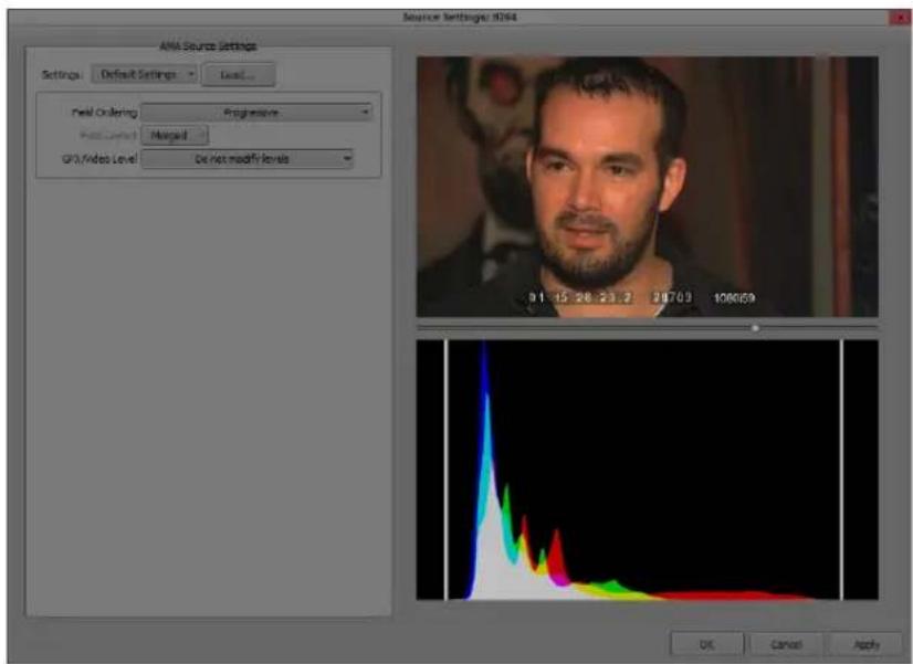
- Drag the video slider to the frame you want to view.
The new frame displays and the histogram updates.
The histogram is a tool that helps you more precisely adjust Source Settings. For more information about the histogram, see “Understanding the QuickTime Source Settings Histogram” on page 424
- Set the appropriate options:
Option Description
| Settings Default | Custom: User created in Avid. |
| Field Ordering Default | Progressive: The image is interpreted as a progressive image.Interlaced - Odd (upper field first) ordered: Adjusts the clip so that the top field is played before the lower field.Interlaced - Even (lower field first): Adjusts the clip so that the lower field is played before the top field. |
| Field Layout(Available when Field Ordering > Interlaced is selected) | Merged (default): Alternates field information.Split: Based on the field ordering selection (Interlaced Odd or Interlaced Even), fields will be split into one over the other. For example, all odd fields are over all even fields. |
| GFX/Video Level Do not modify levels: Leave as is | Expand video levels to graphic levels: Changes the dynamic range from an 601/709 video range (16-235) to RGB range (0-255).Compress graphic levels to video levels: Changes the dynamic range from RGB (0-255) range to an 601/709 video range (16-235). This option is useful if you created a QuickTime movie with graphic levels in AfterEffects and then brought the clip into an Avid editing application. |
- Click Apply.
The changes apply to your clip. You can continue to make additional changes.
If the clip is in the Source viewer, the changes are reflected in the Source viewer and in the Client monitor (if you have one attached).
If you click Cancel after you click Apply, the Set Source Settings window closes with the changes you made.
- Click OK to save your change and close the window.
The system updates the bin column metadata with the new parameters.

If you make changes in the Source Settings window and then relink the clip through AMA again, you still keep all the parameters that you set.
Applying a QuickTime Source Setting
Source Settings lets you choose from a Custom of Default setting. Each source setting has its own color values associated with it.
To apply a source setting to a QuickTime clip:
- Right-click a QuickTime clip in the bin (or Shift-click multiple clips), then choose Set Source Settings.
The Set Source Settings window opens and your clip displays in the viewer.
- Select a setting from the Source Settings menu.
Setting Origin
Default Settings Default
Custom User created in Avid
- Click Apply.
The settings apply to the clip and if the clip is loaded in the Timeline, the video updates and displays in a Client monitor (if one is attached) and the Source monitor.
- Click OK to save your settings and close the window.
The system updates the bin column metadata with the parameters.
If you make additional changes after you select a setting, the system creates a Custom setting and Custom appears in the Settings list. You cannot make changes to a system generated setting, however you can use a system setting and make changes to create your own Custom setting.

The Load button does not apply to QuickTime media.
Understanding the QuickTime Source Settings Histogram
The histogram in the Source Settings window helps you visualize the distribution of color values in an image. You can use the histogram to adjust the Source Settings of your AMA media more precisely while avoiding clipping and color imbalance.

line
| Time | Value | |------|-------| | 0 | 0 | | 1 | 100 | | 2 | 300 | | 3 | 600 | | 4 | 800 | | 5 | 900 | | 6 | 700 | | 7 | 500 | | 8 | 300 | | 9 | 100 | | 10 | 50 | | 11 | 20 | | 12 | 10 | | 13 | 5 | | 14 | 2 | | 15 | 1 | | 16 | 0.5 | | 17 | 0.2 | | 18 | 0.1 | | 19 | 0.05 | | 20 | 0.02 | | 21 | 0.01 | | 22 | 0.005 | | 23 | 0.002 | | 24 | 0.001 | | 25 | 0.0005| | 26 | 0.0002| | 27 | 0.0001| | 28 | 0.00005| | 29 | 0.00002| | 30 | 0.00001| | 31 | 0.000005| | 32 | 0.000002| | 33 | 0.000001| | 34 | 0.0000005| | 35 | 0.0000002| | 36 | 0.0000001| | 37 | 0.00000005| | 38 | 0.00000002| | 39 | 0.00000001| | 40 | 0.000000005| | 41 | 0.000000002| | 42 | 0.000000001| | 43 | 0.0000000005| | 44 | 0.0000000002| | 45 | 0.0000000001| | 46 | 0.00000000005| | 47 | 0.00000000002| | 48 | 0.00000000001| | 49 | 0.000000000005| | 50 | 0.0 | | 51 | 1 | | 52 | 2 | | 53 | 3 | | 54 | 4 | | 55 | 5 | | 56 | 6 | | 57 | 7 | | 58 | 8 | | 59 | 9 | | 60 | 1 | | 61 | 2 | | 62 | 3 | | 63 | 4 | | 64 | 5 | | 65 | 6 | | 66 | 7 | | 67 | 8 | | 68 | 9 | | 69 | 1 | | 70 | 2 | | 71 | 3 | | 72 | 4 | | 73 | 5 | | 74 | 6 | | 75 | 7 | | 76 | 8 | | 77 | 9 | | 78 | 1 | | 79 | 2 | | 80 | 3 | | 81 | 4 | | 82 | 5 | | 83 | 6 | | 84 | 7 | | 85 | 8 | | 86 | 9 | | 87 | 1 | | 88 | 2 | | 89 | 3 | | 90 | 4 | | 91 | 5 | | 92 | 6 | | 93 | 7 | | 94 | 8 | | 95 | 9 | | 96 | 1 | | 97 | 2 | | 98 | 3 | | 99 | 4 | | Note: The actual values may vary due to the random nature of the data generation. The provided values are just an example. The actual values may be different from the generated data. There is no label for the data series.Example of a Source Settings histogram. The histogram plots color values on the horizontal axis and the percentage or proportional number of pixels on the vertical axis. The vertical lines represent the black point (left) and the white point (right), so the area between them is the safe color range.
The histogram plots color values that can be represented by the image bit-depth on the horizontal axis. Therefore, the width of the histogram is the same as the width of the image. The histogram plots the percentage, or proportional number of pixels in the image, with each particular color value on the vertical axis. The vertical axis is scaled according to the height of the maximum value in the plot. Whenever the histogram changes, the vertical axis rescales according to the new maximum.

Pixels with color values that are out of range are grouped into either the maximum or minimum color values on the plot. Spikes in either the highest or lowest color values might indicate loss of color information due to clipping.
Using the MXF AMA Plug-In
Material Exchange Format (MXF) is a wrapper or container format which encapsulates media and rich production metadata into a single file, which is useful for media storage and exchange. It is an open technology that can is implemented by different manufacturers.
MXF is designed to be flexible enough for use in all stages of content creation, from acquisition, to authoring, to distribution. The primary benefit of MXF is that it provides greater workflow efficiency by preserving useful metadata as media files make their way through the content creation process. The MXF format is independent of the type of content that it contains, so an MXF file can contain video and/or audio at any resolution or compression. In many instances MXF files encapsulate media which is already formatted to one of the existing industry standards.
You can select the MXF format when you capture, link, create titles, or render effects. See “Media Creation Settings” on page 1424.
The MXF AMA plug-in is automatically installed when you install your editing application.
A typical workflow is as follows:
- Create a supported MXF file (create a supported MXF file from your third party application, for example: Rhozet or Omneon).
- Move the .mxf file onto your Avid editing system.
- Select File > AMA Link.
You can also right-click a bin and select AMA Link.
The Open dialog box opens.
- From the AMA Plugin Filter menu, select MXF.
- Select the file(s) you want to link. Ctrl+click or Shift+click to select multiple files.
- Click Open.
The MXF clips appear in the active bin. A link icon appears next to the clips.
If the system cannot link a file, an error message displays informing you to open the Console window for more information about the file(s) in error.
If you move the clip from the original drive to another drive on your system, the clip displays as offline in your bin.

If you move a source file from one location to another and then back to the original location, you might need to refresh the bin to redisplay the clip. Close and reopen the bin to refresh the bin.
- Use the linked clips to edit your sequence.
- (Option) Rename the clips to help organize your material.
- Consolidate or transcode your sequence or clips.
The media consolidates to the destination you set in the Media Creation dialog box.

When you consolidate, if you want to keep your AMA clips linked to the original source, select the option “Keep Master clips linked to media on the original drive,” in the Copying Media Files dialog box.
Workflow for Editing Clips with Ancillary Data and AMA
The following steps describe a typical workflow for editing XDCAM or MXF clips with ancillary data and AMA.

Do not mix AMA and traditional workflows. Either use AMA or use the traditional import/batch import workflow.
You should be aware of the following:
- You can link to the ancillary data clip without an Avid input/output hardware, however, in order to view the ancillary data in a monitor, an Avid Nitris DX or Avid Mojo DX device is required.
- If you consolidate the XDCAM or MXF clip or the sequence that contains the XDCAM or MXF clip with ancillary data, the ancillary data track stays with the consolidated clip or sequence. In addition, the Ancillary Data bin column populates with the DID and SDID numbers once you consolidate or transcode the clip with the ancillary data.
A typical workflow is as follows:
- The Sony XDCAM or MXF AMA plug-in should be installed on your system.
- For XDCAM, install the appropriate Sony XDCAM drivers.
- For an XDCAM clip with ancillary data, insert the XDCAM disk.
The system links the XDCAM clip with ancillary data into a bin. The media itself remains on the disk. The clips point directly to the media on the disk.

Ancillary data is only supported with high resolution XDCAM clips. A proxy clip does not contain a data track, however once you relink to the high resolution XDCAM clip, the data track comes online.

If you use multiple cards and you remove one of the cards, your media displays offline.
- For an MXF clip with ancillary data, select File > Link to AMA File(s).
The Select file(s) for AMA linking dialog box opens. - From the AMA Plugin Filter menu, select MXF.
- Select the file(s) you want to link. Ctrl+click or Shift+click to select multiple files.
The MXF clip appears in the bin along with a new Ancillary Data bin column.

For information about AMA, see “The Avid Media Access (AMA) Workflow” on page 374.
- Use the master clips to edit the sequence.
When you load the clip into a sequence, a Data track appears which contains the ancillary data.
- You can then transcode or consolidate your sequence or clips.

When you consolidate, if you want to keep your AMA clips linked to the original source, select the option "Keep Master clips linked to media on the original drive," in the Copying Media Files dialog box.
When you consolidate the XDCAM or MXF clip or the sequence that contains the XDCAM or MXF clip with ancillary data, the ancillary data track stays with the consolidated clip or sequence.

For information on consolidating your sequence, see “Consolidating Media” on page 449. For information on transcoding your sequence, see “Using the Transcode Command” on page 455.
Understanding the Source Settings Histogram
The histogram in the Source Settings window helps you visualize the distribution of color values in an image. You can use the histogram to adjust the Source Settings of your AMA media more precisely while avoiding clipping and color imbalance.

line
| X | Y | |----|------| | 0 | 0.0 | | 1 | 0.5 | | 2 | 1.2 | | 3 | 2.8 | | 4 | 4.5 | | 5 | 6.0 | | 6 | 7.5 | | 7 | 8.0 | | 8 | 7.0 | | 9 | 6.0 | | 10 | 5.0 | | 11 | 4.0 | | 12 | 3.0 | | 13 | 2.0 | | 14 | 1.5 | | 15 | 1.0 | | 16 | 0.8 | | 17 | 0.6 | | 18 | 0.5 | | 19 | 0.4 | | 20 | 0.3 | | 21 | 0.2 | | 22 | 0.1 | | 23 | 0.05 | | 24 | 0.02 | | 25 | 0.01 | | 26 | 0.005| | 27 | 0.002| | 28 | 0.001| | 29 | 0.0005| | 30 | 0.0002| | 31 | 0.0001| | 32 | 0.00005| | 33 | 0.00002| | 34 | 0.00001| | 35 | 0.000005| | 36 | 0.000002| | 37 | 0.000001| | 38 | 0.0000005| | 39 | 0.0000002| | 40 | 0.0000001| | 41 | 0.00000005| | 42 | 0.00000002| | 43 | 0.00000001| | 44 | 0.000000005| | 45 | 0.000000002| | 46 | 0.000000001| | 47 | 0.0000000005| | 48 | 0.0000000002| | 49 | 0.0000000001| | 50 | 0.00000000005| | 51 | 0.0 | | 52 | 0.5 | | 53 | 1.5 | | 54 | 3.5 | | 55 | 6.5 | | 56 | 9.5 | | 57 | 12.5 | | 58 | 15.5 | | 59 | 18.5 | | 60 | 21.5 | | 61 | 24.5 | | 62 | 27.5 | | 63 | 31.5 | | 64 | 35.5 | | 65 | 39.5 | | 66 | 43.5 | | 67 | 47.5 | | 68 | 51.5 | | 69 | 55.5 | | 70 | 59.5 | | 71 | 63.5 | | 72 | 67.5 | | 73 | 71.5 | | 74 | 75.5 | | 75 | 79.5 | | 76 | 83.5 | | | |Example of a Source Settings histogram. The histogram plots color values on the horizontal axis and the percentage or proportional number of pixels on the vertical axis. The vertical lines represent the black point (left) and the white point (right), so the area between them is the safe color range.
The histogram plots color values that can be represented by the image bit-depth on the horizontal axis. Therefore, the width of the histogram is the same as the width of the image. The histogram plots the percentage, or proportional number of pixels in the image, with each particular color value on the vertical axis. The vertical axis is scaled according to the height of the maximum value in the plot. Whenever the histogram changes, the vertical axis rescales according to the new maximum.

Pixels with color values that are out of range are grouped into either the maximum or minimum color values on the plot. Spikes in either the highest or lowest color values might indicate loss of color information due to clipping.
Your Avid editing application draws separate histograms for the red, green, and blue color components. The histograms for each color stack on top of one another, with the fill color changing appropriately to indicate overlap. The following illustration shows the colors produced by overlap.

natural_image
Venn diagram of three overlapping circles in red, green, and blue against black background (no text or symbols)Adjusting the Source Settings Histogram
You can adjust the Source Settings Histogram in two ways. You can toggle drawing a histogram for an individual color, and you can zoom the vertical axis.
To adjust the Source Settings Histogram:
Right-click anywhere inside the histogram graph, and then select one of the following options.
Option Result
Red
Green
Blue
Enables or disables the histogram display for the selected color. A check mark
indicates that the histogram for that particular color displays.
Option Result
Zoom In Zooms in on the lower half of the vertical axis.
Changes the scaling of the vertical axis so that the height is half that of the maximum value in the plot. You can zoom in indefinitely to display, for example, 1/4, 1/8, or 1/16 of the maximum value.
Zoom Out Zooms out of the vertical axis by a factor of two.
Changes the scaling of the vertical axis to be twice that of the maximum value in the plot. You can zoom out indefinitely to display, for example, 4, 8, or 16 times the height of the maximum value.
Reset Zoom Resets the zoom so that the vertical axis boundary is equal to the maximum value in the plot.

Working with Export Volumes
The Avid editing application supports the creation of AS-02 Export Volumes. AS-02 is a specification for grouping multiple versions of program content into one single bundle. These bundles provide an efficient approach for working in a file-based environment.
For example, if you have a sequence with an English audio mix and a sequence with the same video but with a Spanish audio mix, creating an AS-02 Export Volume allows you to have all the program elements contained in a bundle without redundancy. The same video essence file can be the source for the both the English and the Spanish versions. This is useful if you want to save time on export and reduce used disk space.
The basic workflow is to create a new Export Volume Bin, copy the sequence or sequences you want to the Volume Bin, commit the assets in the Export Volume Bin, and then archive the AS-02 bundle folder. You can also link to an existing AS-02 bundle.
The bundle folder structure is shown below. This is for reference only. These elements will be automatically created for you when you commit an Export Volume Bin.
• T h e Asset.mxf file is the sequence (version).
- The Manifest.xml file lists the creator information, creation date, version information and a list of all the files and folders in the bundle.
- The Shim.xml file is used as a template or settings file that constrains the rules for a specific facility.
• The Media folder contains all the media files included in the bundle.
- The Extra folder contains a copy of the unflattened sequence (AAF composition only). The Extra folder can also contain any other files you want to keep with the bundle, such as scripts, graphics, etc.

flowchart
graph TD
    A["Asset"] --> B["Asset.mxf"]
    A --> C["Manifest.xml"]
    A --> D["Shim.xml"]
    A --> E["Media"]
    A --> F["Extra"]
    G["+"] --> H["+"]
    I["+"] --> J["+"]
Creating an Export Volume
You can create an export volume to place all program elements into a bundle.
To create a new export volume:
- Select File > New Export Volume.
The Export Volume dialog box opens.

- Select a Volume Type, for example AS-02.
- Click Set to select the path where you want the Export Volume to reside.
- Enter a name for the volume.
-
Click Set to select the path to the shim template you want to use.
-
AS-02 supports J2K, Uncompressed 10b RGB, DNxHD, AVCI, IMX and Uncompressed 8b for SD.
- All DNxHD templates are tuned to the DNxHD 220x family. That means depending on the project type, selecting a DNxHD template will export to a DNxHD 10b codec.
- AS-02 Shim templates for all supported resolutions are located in the Supporting Files folder.
- You can choose any one of these templates depending on the desired output codec/format.
- You can also create a folder named Default at the root of the AS-02 Templates folder where you can place custom templates. For example, you can duplicate the AS-02_Shim_DNxHD_1080i_59.94.xml found in the DNxHD folder, modify it (to a different audio sample rate or DNxHD resolution) and place the duplicate in the Default folder. This duplicated template will now be the default template for 1080i59 projects.
-
DNxHD resolutions are supported except DNxHD 100 and DNxHD 36.
-
Click OK.
The Export Volume bin opens.

Left to right: Export Volume Type, Path to Asset folder, Properties button, Commit button
Moving Assets to an Export Volume
You can move the desired assets to the Export Volume.
To move assets to the Export Volume:
- Open the bin that contains the sequence or sequences you want to write to the Export Volume.
- Select and drag the sequence(s) to the Export Volume.
A copy of the sequence(s) appears in the Export Volume.


You can only drag sequences to an AS-02 Export Volume Bin. If you try to drag master clips, effects, titles, etc, you will receive a message indicating that some assets that you selected could not be dragged to the Volume Bin. If you receive this message, open the Console Tool to see the list of items that were not written.
Committing Assets to an Export Volume
Once you commit the assets, the sequence is flattened to the OP1b format, the video is encoded to the J2K codec and audio saved as PCM.
To commit the assets to the Export Volume:

- Open the Export Volume that contains the sequence(s) to commit.
- Click the Commit button to commit the assets to the AS-02 bundle.
The sequence along with its associated media files populate the Export Volume.
Note the Media Status column indicates the committed status of each asset in the volume. Green indicates the asset is committed. Yellow indicates the asset is not committed. Red indicates the asset is offline.
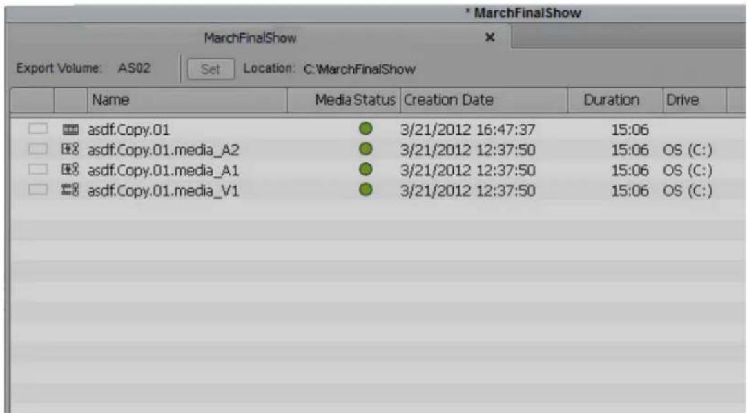
Once the assets are committed, the following are written to the bundle folder:
- The sequence (version)
- The essence files
- The manifest (a file listing the creation date, creator, version information and a list of all the files and folders in the bundle.)
- The shim file (used as a template or settings file that constrains the rules for the specific facility)
- An AAF copy of the unflattened sequences(s) in the Extras folder
Archiving the AS-02 Bundle
Once you have committed the assets to the Export Volume, you can archive the AS-02 bundle.
To archive the Assets Folder.
- Locate the AS-02 bundle folder by accessing the path you set in step 4 of Creating an Export Volume.
- Copy the AS-02 bundle folder to your archive server.
Linking to an existing AS-02 Bundle
You can open an existing AS-02 bundle.
To link to an existing AS-02 Volume:
- Select File > Link to Volume for Export.
- Select the folder where the AS-02 bundle resides.
- Click OK.
- A new volume bin opens with the AS-02 assets.
You can also choose to Link to AMA Volume if you want to open the assets as Read-only in a classic bin.
AS-11 Support
The Avid editing application supports the Advanced Media Workflow Association (AMWA) AS-11 specification. This specification is used in broadcast environments. The specification defines a set of rules that constrain the specification. AS-11 is an OP1A MXF file format for the delivery of finished programming. This specification requires program segment markers. Program segmentation defines specific regions of a show, for example a segment marker for the A-block, B-block and C-block. See “Adding Spanned Markers While Editing” on page 526 to apply these markers before you export your sequence.
To export a sequence as AS-11:
- Select the sequence you want to export as AS-11.
- Click File > AMA File Export, or right click the sequence and select AMA File Export. The AMA File Export dialog opens.

- Select File Type AS-11.
- (Option) Select the Use Marks or Use Enabled Tracks option.
When you select Use Marks, your Avid editing application uses current IN and OUT points in the selected clip or sequence to determine starting and ending frames for the export. To export the entire clip or sequence, deselect this option or mark the entire clip or sequence.
When you select Use Enabled Tracks, your Avid editing application exports the tracks that are enabled in the Timeline. To export all the tracks in the sequence, deselect this option.
- Click the Directory Set button to and browse to the location where you want the AS-11 file saved.
- Click Select Folder.
-
Select the Shim Set button to locate the Shim file you want associated with the export and click Open. Avid provides shims in the following location:
-
(Windows) Program Files/Avid/EditingApplicationName/SupportingFiles
- (Macintosh) MacintoshHD/Applications/EditingApplicationName/SupportingFiles
The Descriptive Metadata populates in the window depending upon the shim you selected.
- Enter the specific program information in the Descriptive Metadata fields.
This is the descriptive data stored in the AS-11 export that describes Essence data. For example, the language, series title, program title, episode title, etc.
-
(Option) Click Save Profile.
-
(Option) Enter a name for the Profile.
- Click OK.
A profile containing all the metadata that was entered in the Descriptive Metadata fields is saved. Once you save and name a Profile, you can use the Profile as a template by loading it the next time you are setting up an AS-11 sequence for export.
- Click Save.
The AS-11 file is exported to the selected directory.
When you perform an AMA link to the AS-11 sequence, the spanned markers are represented in the source Timeline and all the descriptive metadata appears in the Bin columns.
11 Managing Media Files
When you capture footage, the system creates digital media files on the media drives connected to your system. In addition to the bins where you organize the clips that reference these media files, your Avid editing application provides tools for directly managing these media files. These tools and features are described in the following topics:
• Working with Media Files in an Avid Interplay Environment
• Using Avid Editing Systems in an Avid LANshare Workgroup
• Viewing Media with a 100Base-T Connection to Avid ISIS
• Understanding Drive Mounting
- Mounting and Unmounting Drives
• Using the Media Tool
- Consolidating Media
• Using the Consolidate Command
• Using the Transcode Command
• Background Consolidate and Transcode
- Loading the Media Database
• Refreshing Media Directories
- Deleting Unreferenced Clips and Media
- Backing Up Media Files

In an Avid Interplay environment, your Avid editing application uses the Interplay Media Indexer service to keep track of media files in the locations that you identify. As a result, features such as the Media tool and relinking work differently in an Interplay environment. This chapter includes notes and cross-references where appropriate. For more information, see “Using MultiRez and Dynamic Relink” on page 1245 as well as the Interplay documentation.
Working with Media Files in an Avid Interplay Environment
If you are using your Avid editing system in an Avid Interplay environment, you can use Avid's media asset manager, the Avid Interplay Engine, to share media files between systems. The Interplay Engine, installed on the Avid Interplay server, is a media database that lets you search the large number of media objects (master clips, sequences, effects, and any other type of object that references digital media) in the Avid shared storage environment. You can also use the Interplay Engine to manage sequences and other media objects whose media is no longer online. You can then search for these objects, view information about them such as the source tape name, obtain the source footage, and rerecord or recapture it.
If you want to transfer media from one workgroup to another, you can use the Interplay Transfer application. Interplay Transfer receives and queues transfer requests from one or more clients. Transfers are then initiated by the Interplay Transfer server to off load the client. For more information about the Transfer setting, see the Avid Interplay Transfer Setup and User's Guide.
You can also use Avid Interplay Transfer to share files between workgroups. For more information about the Interplay Engine and Avid Interplay Transfer, see the Avid Interplay Access User's Guide and the Avid Interplay Transfer Setup and User's Guide.
Configuring Avid Editing Systems for the Interplay Engine and Interplay Transfer
Before you can interact with the Avid Interplay Engine and Avid Interplay Transfer, you need to configure your Avid editing application with the required Interplay settings.
You must specify the Interplay Server location to let your Avid editing application know where to look for the Interplay Engine on the network. After you specify the network settings, you can check in clips to and check out clips from the Interplay database. For more information about Interplay settings, see “Configuring Interplay Settings on the Editing Workstation” on page 1144 and the Avid Interplay Engine and Avid Interplay Archive Engine Administration Guide.
The Interplay Server setting is a Project Setting that applies to all users of a particular Avid editing system. If you want to access another asset manager, you must modify the Interplay Server settings to reflect the server.
The directory defined in your Interplay Project settings identifies the Interplay folder location to which you check in media objects. You can check out objects from a different asset manager by dragging clips from that asset manager to a bin without changing the Interplay Project settings.
Using Avid Editing Systems in an Avid Workgroup Environment
When you work with Avid Interplay, you belong to a workgroup that allows you open a bin with assets stored in the Interplay database. To read and write media to the database you first need to mount a workspace. For information on mounting workspaces, see “Mounting Workspaces on an Avid ISIS System” on page 1156.

When you are in a workgroup environment using an asset manager server with an anti-virus utility, you need to turn off any auto-protection feature when you access the asset manager. You can then turn the auto-protection feature back on. You need to perform this each time you access the asset manager. In addition, do not perform a live update while the system use is high. For more information, see your anti-virus documentation.
For information on disconnecting your Avid editing application from the Interplay environment, see the topic “Disconnecting from the Interplay Environment” in the Avid Interplay Help.
Using Avid Editing Systems in an Avid LANshare Workgroup
You can use your Avid editing system as a client in an Avid LANshare workgroup. A LANshare workgroup lets you share media with other clients connected to a high-performance server through an Ethernet network.
For complete information on using a LANshare workgroup, including system requirements and supported resolutions, see the LANserver release notes and documentation.

Because LANshare workgroups and PortServer workgroups do not support all Avid resolutions, make sure you specify a supported resolution in your Avid editing application. For information on supported resolutions, see the LANserver system or PortServer system documentation.
When you use your Avid editing application with the LANserver system, you need to set up the client so LANshare workspaces are recognized when you start your Avid editing application.
To enable the client to recognize LANshare workspaces:
- Open a bin.
- Double-click PortServer in the Settings list of the Project window
The Port Server Settings dialog box opens. - Select "Auto-connect to LANshare at Launch."
- Click Connect, and then click OK.
The dialog box closes, and auto-connect is set.
Viewing Media with a 100Base-T Connection to Avid ISIS
Avid editors can access MPEG-2 low-resolution video and MPEG-1 Layer II (or MP2) compressed audio stored on an Avid ISIS media network. This is useful if you connect to the media network with a 100Base-T connection in a Zone 3 configuration, instead of the higher bandwidth connection used for Avid ISIS clients in a Zone 1 or Zone 2 configuration. For more information on Avid ISIS media networks, see the Avid ISIS Setup Guide.
You cannot output, consolidate, or transcode media using MP2 compressed audio. Instead, use dynamic relink to link the low-resolution media to the high-resolution source media stored on the media network. You can then output or transcode the high-resolution media.
Understanding Drive Mounting
By default, all media drives connected to your system are listed and can be seen by your Avid editing application. You can remove one or more drives from the list at any time by using the Unmount command. For example, if you want to use only some of your drives for a particular project, select Unmount to prevent other drives from appearing in your Avid editing application.
If the drive being ejected supports the auto-eject feature (for example, Jaz ^® drives), the command ejects the disk from the drive. The Unmount command does not remove drives from the Windows system.
You can unmount one or several drive volumes mounted on the desktop at any time from within your Avid editing application. You can also remount all the drives and return them to the desktop. However, you cannot mount selected drives because your Avid editing application cannot interface with selected drive individually. For more information, see “Mounting and Unmounting Drives” on page 443.
This is useful in several circumstances:
- If you work with optical drives for backup and retrieval of low-resolution material, you can unmount drives and mount them as needed to avoid cluttering the desktop during normal use.
- If you work with an extensive array of fixed-storage drives, which might involve many partitions divided among several projects, you can selectively mount and unmount drives according to use.
- If you work with an Avid shared storage environment, you might have to unmount and remount icons on the desktop. See “Working with Bins and Projects in an Avid Shared Storage Environment” on page 100.

On systems with multiple media drives, unmounting unused drives can improve the performance of the Media tool. You need to unmount the drives before you open the Media tool. See “Using the Media Tool” on page 443.

If you need to physically add or remove drives, see the documentation that came with your drive. You cannot physically add or remove drives from your Avid editing application. Before you physically remove or add drives, shut down your system completely.
Mounting and Unmounting Drives
For more information on mounting and unmounting drives, see “Understanding Drive Mounting” on page 442.
To mount all drives:
▶Select File > Mount All.
All drives turned on and connected to the system become available to your Avid editing application.
To unmount a drive or make a drive unavailable to your Avid editing application:
- With your Avid editing application running, select File > Unmount.
The Unmount Disk or Drives dialog box opens.
The list displays all drives currently available.
- Select a drive to unmount.
- Ctrl+click (Windows) or Command+click (Macintosh) to select additional drives.
- Click Unmount.
The drives are no longer available to your Avid editing application.

If you receive an error message that prevents you from unmounting a drive, it might be that you have Avid Media Access (AMA) enabled. AMA does not require you to mount and unmount drives. AMA is on by default. To turn off AMA (and unmount your drive), see “Selecting the AMA Settings” on page 378.
Using the Media Tool
The Media tool is your window into the captured video and audio data files stored on your media drives. The Media tool provides similar database tools for manipulating digital media files to those provided by bins for manipulating clips and sequences.
The Media tool displays media that is stored on local drives (drives directly connected to the Avid editing system) and on unmanaged shared storage (shared storage that is part of an Avid shared storage network but is not managed by an Avid asset manager).
In an Interplay environment, the Media tool displays only media that is stored on local drives, see “Using the Media Tool in an Avid Interplay Environment” on page 445. Use the Media tool to search for media on local drives, and use the Interplay Engine to search for media on shared drives.
Basic Media Tool Features
The Media tool provides many of the same controls for viewing and managing information that you use with bins:
- The three display options in the Media tool function like the bin display views: Text view, Frame view, and Script view.
- You can use Text View headings and options for columns of clip and media file data. You can also use procedures such as customizing the display of columns, moving within columns, and sorting information, as described in “Using Text View” on page 325.
- You can use the same Frame view options described in "Using Frame View" on page 330.
- You can use the same Script view options described in “Using Script View” on page 332.
- The Media Tool Fast menu gives you quick access to the same commands available in the Bin Fast menu.
- You can highlight, move, copy, duplicate, delete, sort, and sift clips in the Media tool. You can also select media relatives, source clips, and unreferenced clips, as described in “Bin Procedures” on page 333.
- Media Tool database and display options are saved as User settings. When you close the Media tool, the view you are in (Brief, Frame, Script, or Text) is saved and any customizations of columns are saved.
- You have the option of saving a custom view of the Media tool. Any view created in the Media tool is available from all bins and all custom bin views are available in the Media tool from the Views menu. For more information on creating customized views, see “Saving a Custom Bin View” on page 329.

Media Tool views are saved as User settings and appear in the Settings list in the Project window as bin views.
- You can print Media Tool data by using the same procedures for printing bins, as described in “Printing Bins” on page 373.
The Media tool also has a number of unique functions:
- Unlike a bin, the Media tool can display all the tracks captured for each clip as separate media files. Therefore, when you view, delete, and manipulate files, you have the added option of specifying individual video and audio tracks.
- Unlike a bin, the Media tool does not display sequences and subclips. Only master clips, precompute (rendered effect) clips, and associated media files are available for display.
- The following Bin menu commands do not apply to the Media tool: Batch Capture, Batch Import, Relink, Modify, AutoSync, and AutoSequence. You must perform these functions from a bin.
Using the Media Tool in an Avid Interplay Environment
On an editing system in an Avid Interplay environment, the Media tool displays only media that is stored on local drives. When you use the Media tool to search for media on a local drive, the Interplay Media Indexer (an Interplay service) searches its database and determines if media is online. If the media is online, it tells the Media tool to display it. However, the Media Indexer keeps track of media only if the media is on indexed storages (storages for which Media Indexer is configured).
If some media seems to be missing when you use the Media tool, that media might be stored in a folder not indexed by Media Indexer. If you want to see all local media in the Media tool, all your local storages must be properly indexed. For information on configuring Media Indexer, see the installation documentation for Avid Interplay.
Opening the Media Tool
To open the Media tool:
- Select Tools > Media Tool.
The Media Tool Display dialog box opens.

- Select the media drives from which to load by doing one of the following:
▶In the Media Drive(s) list, select individual media drives.
▶Click the All Drives button.
The Media tool loads the media database only for the drives you select. The more drives you select, the more memory is required for the Media tool to open.
- Select the projects to load by doing one of the following:
▶In the Projects list, select individual projects.
▶Click the Current Project button.
▶Click the All Projects button.
Only projects with associated online media and the current project appear in the Project(s) list in the Media Tool Display dialog box.
- Select Master Clips, Precompute Clips, Media Files, or any combination of the three.
- Click OK.
The Media tool opens.

Example of media objects in the Media tool. Top to bottom: a master clip, a precompute clip, and a media file.
Deleting Media Files with the Media Tool
You can use the Media tool to delete selected media files without harming the related master clips, subclips, and sequences.

If you use the Media tool to delete selected media files, you no longer have access to visuals of the deleted material. If you load a clip for which a media file has been deleted, a black screen appears with the words "Media Offline." If you need to use those clips again, you must recapture from tape or reimport graphics.
Depending on your needs, you can do the following:
- Delete selected audio or video tracks and retain other tracks from a clip.
- Delete entire sets of media files and related clips from within the Media tool.
- Delete all unrelated media upon completion of a project, and retain only the media required for playback of a finished sequence as described in “Consolidating Media” on page 449.
To delete selected media files:
- Select Tools > Media Tool.
- Select one or more media files (audio, video, or both) or master clips whose media files you want to delete.
- Do one of the following:
▶Select Edit > Delete.
▶Press the Delete key.
The Delete Media dialog box opens.
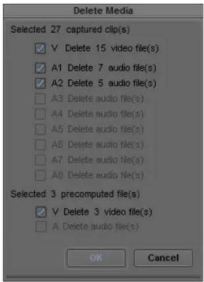
- Select the media objects that you want to delete:
Option Description
| Video media file (V) | After deletion, the master clip linked to that file is black, with the message “Media Offline” displayed. Related subclips and sequences are affected in the same way. |
| Audio media file (A1, A2, A3, A4, A5, A6, A7, A8) | After deletion, the master clip linked to that file is silent. Subclips and sequences created from the master clip are affected in the same way. |
| Precompute media file (V, A) | After deletion, the section of the sequence with the effect is black, and the message “Media Offline” is displayed. |
| Audio mixdown file (A) | After deletion, the section of the sequence with the mixdown is silent. |
- Click OK.
A dialog box opens, asking you to confirm the deletion.
- Click Delete.
The selected media files are deleted.
Consolidating Media
When you consolidate media files, your Avid editing application finds the media files or portions of media files associated with selected clips, subclips, or sequences. It then makes copies of them, and saves the copies on a target drive that you specify.
There are three basic reasons to use the Consolidate feature:
- To copy media onto one drive for storage or transfer to another system.
- To keep only the media required to play back a sequence, and delete the rest to use less storage space.
- To create backup files.

Because the Media tool displays only master clips, you cannot consolidate subclips or sequences with the Media tool. You can consolidate master clips, subclips, and sequences in a bin.
The Consolidate feature operates differently, and provides different advantages, depending upon whether you are consolidating master clips, subclips, or sequences.
Master Clips
When you consolidate a master clip, your Avid editing application creates exact copies of the media files. If you link the original master clip to the new files, your Avid editing application creates a master clip with the file name extension .old that remains linked to the old files. If you maintain the link between the original master clip and the old media files, your Avid editing application creates a new master clip with the file name extension .new that is linked to the new media files.
The new master clips are also numbered incrementally beginning with .01. Consolidating master clips does not save storage space because your Avid editing application copies the same amount of media for each clip.
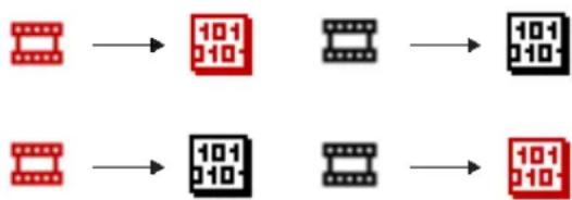
flowchart
graph LR
    A["Red Film Block"] --> B["10-1 0-10"]
    C["Black Film Block"] --> D["10-1 0-10"]
    E["Red Film Block"] --> F["10-1 0-10"]
    G["Black Film Block"] --> H["10-1 0-10"]
Consolidating a master clip (original clips and media files in red, new clips and media files in black). Top: in this scenario, the original master clip remains linked to the original media file (for example, on drive A), and the new master clip (which receives a .new.01 file name extension) is linked to a new copy of the original media file (on drive B). Bottom: in this scenario, the original master clip is linked to a new copy of the original media file (on drive B), and the new master clip (which receives a .old.01 file name extension) is linked to the original media file.
Subclips
When you consolidate a subclip or group of subclips, your Avid editing application copies only the portion of the media files represented in the subclip and creates a new master clip that is the duration of the subclip and a new subclip. The file name extension .new is attached, along with incremental numbering beginning with .01.

flowchart
graph TD
    A[" Filmstrip"] --> B[" 101/10 "]
    B --> C[" Digital 10/1h "]
    A --> D[" Filmstrip"]
    B --> E[" Filmstrip"]
    C --> F[" Filmstrip"]
Consolidating a subclip. Left: the original master clip, the subclip created from it, and its original media file. (on, for example, drive A). Right: the new master clip, the new subclip, and the smaller subclipped copy of the original media file (on drive B).
Sequences
When you consolidate a sequence, your Avid editing application copies only the portions of media files edited into the sequence and creates new master clips for each clip in the sequence. The file name extension .new is attached to the master clips, along with incremental numbering beginning with .01. The sequence is not renamed but is automatically relinked to the new media files.
Consolidate finished sequences to:
- Create backup files.
- Preserve only the captured media required for playback, and delete the rest to use less storage space.
• Gather dispersed media onto one drive for storage or transfer to another system.

Because a consolidated sequence is linked to the new files by default, consider duplicating the sequence each time you consolidate if you need to maintain links to the original files.
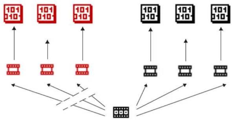
flowchart
graph TD
    A["101 010"] --> B["Input"]
    C["101 010"] --> D["Input"]
    E["101 010"] --> F["Input"]
    G["101 010"] --> H["Output"]
    I["101 010"] --> J["Output"]
    K["101 010"] --> L["Output"]
    M["101 010"] --> N["Output"]
    O["101 010"] --> P["Output"]
    Q["101 010"] --> R["Output"]
    S["101 010"] --> T["Output"]
    U["101 010"] --> V["Output"]
    W["101 010"] --> X["Output"]
    Y["101 010"] --> Z["Output"]
Consolidating a sequence. Left: the original clips and their media files — consolidating breaks the links between the sequence and these clips. Right: the new clips and their copied media files — the sequence now links to these new clips.
Using the Consolidate Command
To consolidate master clips, subclips, or sequences:
- If you are consolidating a sequence, duplicate the sequence to maintain links to the original files, if necessary, and render any unrendered effects.
- Select a clip or sequence.
- Select Clip > Consolidate/Transcode.

If you have any compressed audio (MP2 audio) in the clip or sequence you selected to consolidate or transcode, a message appears informing you that selected items contain MP2 audio and cannot be consolidated or transcoded. You should relink this MP2 audio to an uncompressed audio format. If you do not relink to an uncompressed audio format, the selected clip or sequence with the MP2 audio is skipped.
The Consolidate/Transcode dialog box opens.

- Select Consolidate in the upper left corner.
- In the Target Drive(s) area, select a drive or drives.
- Select the appropriate options.
Option Description
| Video, audio and data on same drive(s) | Select to store the consolidated media files on the same target drive. Deselecting this option lets you select separate drives for the audio, video and data media files. |
| Handle length n frames | If you are consolidating subclips or sequences, type a handle length for the new clips, or accept the default: leave it at 60 frames (NTSC), 50 frames (PAL), or 24 frames (progressive). The handle length is the number of frames outside the IN and OUT points that you can use for dissolves and trims with the new, shorter master clips. |
| Create new sequence(s) Select this option to create a new sequence from the consolidated clips (appears only if you selected a sequence). | |
| Delete original media files when done | Select to delete original media files automatically. |
| Skip media files already on the target drive | Select to bypass files if some related media files are already located on the target drive. |
| Relink selected clips to target drive before skipping | Select to ensure that all selected clips are linked to media on the target drive. This option appears when you select “Skip media files already on the target drive.” |
| Consolidate all clips in a group edit | Select to copy media for all clips in a group edit, for consolidating a group clip or a sequence that contains group clips.For more information on group clips, see “Understanding Grouping and Multigrouping Clips” on page 1292. |
| Convert Audio Sample Rate Select this option to convert any sample rates not set in the Sample Rate menu in the Main tab in the Audio Project Settings window. For information on setting the sample rate, see “Changing the Audio Sample Rate for Sequences and Audio Clips” on page 834. | |
| Target Audio Sample Rate | Select a sample rate for the sequence. |
Convert Audio Bit Depth Select this option to convert any sample rates not set in the Sample Rate menu in the Main tab in the Audio Project Settings window. For information on setting the sample rate, see “Changing the Audio Sample Rate for Sequences and Audio Clips” on page 834.
Target Audio Bit Depth Select either 16 bit or 24 bit.
Convert Audio Format Select this option to convert the audio to the target audio format.
Option Description (Continued)
Target Audio Format Select either OMF (WAVE), OMF(AIFF-C), or MXF (PCM) audio format. See “Audio Projects Settings: Main Tab” on page 1354.
- Click Consolidate in the lower right corner.
The Copying Media Files dialog box opens.
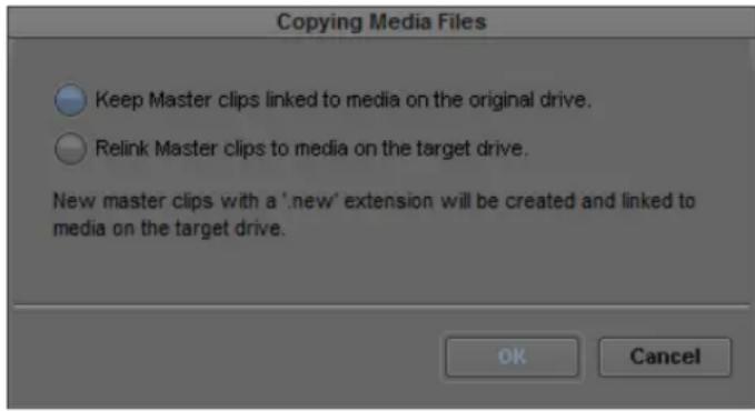
- Select an option for how you want your clips to link to the new media.

If you want to keep your AMA clips linked to the original source, select the option “Keep Master clips linked to media on the original drive.”
For more information, see “Consolidating Media” on page 449.
- Click OK.
Your Avid editing application creates new media files and new clips which are linked according to your selection.
Another way to back up media files is to copy them directly onto another hard drive by using the Windows desktop or the Macintosh desktop. You cannot, however, take advantage of the storage-saving features of the Consolidate command, and it is more difficult to identify particular media files when searching directly through folders.

Do not make copies of media files from the Windows desktop or the Macintosh desktop while your Avid editing application is running. Also, do not keep duplicate copies of media files online; either delete the originals, take the backups offline, or store the backups in a folder with a different name.
Using the Transcode Command
The Transcode option in the Consolidate/Transcode dialog box lets you create new clips and new media files that use a different resolution. If you have a sequence composed of clips that use different resolutions, you can use the Transcode feature to create a sequence in which all clips use a single resolution. The Transcode option also lets you convert from OMF to MXF, and from MXF to OMF, except in HD projects where MXF is the only available format.

The transcode option does not apply to a data clip.

For information to prepare a RED clip for transcode, see “Preparing your RED Clip for Transcode, Mixdown, or Render” on page 412.

Even if you change the resolution to a higher quality resolution, your footage will not look better than the resolution you selected for capture. For example, if you capture your video at 20:1 to save space and then transcode the sequence to 1:1, the sequence will not look uncompressed.
New clips created through the Transcode operation are in the project format. When you transcode a clip across formats, for example if you transcode a 16:9 clip in a 4:3 project, the Reformat bin setting determines how the clip is conformed to the new format. For more information, see “Modifying the Reformat Attribute for a Clip” on page 598.
To use the Transcode option:
- Select a clip or sequence in a bin.
- Select Clip > Consolidate/Transcode.

If you have any compressed audio (MP2 audio) in the clip or sequence you selected to consolidate or transcode, a message appears informing you that selected items contain MP2 audio and cannot be consolidated or transcoded. You should relink this MP2 audio to an uncompressed audio format. If you do not relink to an uncompressed audio format, the selected clip or sequence with the MP2 audio is skipped.
The Consolidate/Transcode dialog box opens.

- Select Transcode in the upper left corner.
- In the Target Drive(s) area, select a drive or drives.
- In you are an Interplay environment, with Dynamic Relink enabled, select whether or not to create new master clips for the transcoded media.
For more information, see “Understanding How Clips are Associated with Multiple Resolutions” on page 1251.

The Create new clips check box in the Consolidate/Transcode dialog box
- Click the Target Video Resolution menu, and select a video resolution.

If your project uses an HD resolution, you cannot select OMF as a file format. MXF is selected by default.
- Select the appropriate options.
Option Description
| Video and audio on same drive(s) | Select to store the transcoded media files on the same target drive. Deselecting this option lets you select separate drives for the audio and video media files. |
| Handle length n frames | If you are transcoding subclips or sequences, type a handle length for the new clips, or accept the default: leave it at 60 frames (NTSC) or 50 frames (PAL). The handle length is the number of frames outside the IN and OUT points that you can use for dissolves and trims with the new, shorter master clips. |
| Create new sequence(s) | Select this option to create a new sequence from the transcoded clips. |
| Create new clips In an Interplay environment, with Dynamic Relink enabled, select this option to create new master clips for the transcoded media. If you do not select this option, the existing master clip is associated with both the original media file and the transcoded media file. For more information, see “Understanding How Clips are Associated with Multiple Resolutions” on page 1251. | |
| Convert Video Select this option to convert the video to the target video resolution. | |
| Target Video Resolution | Select a video resolution for the sequence. |
| Include reformatted clips already at target resolution | Select this option if you want to include reformatted clips in the sequence that are already at the target video resolution.Your Avid editing application does not normally transcode clips in a sequence that are already at the target video resolution. However, you might want to include reformatted clips at the target resolution to preserve the reformatting. |
| Convert Audio Sample Rate | Select this option to convert any sample rates not set in the Sample Rate menu in the Main tab in the Audio Project Settings window. For information on setting the sample rate, see “Changing the Audio Sample Rate for Sequences and Audio Clips” on page 834. |
| Target Audio Sample Rate | Select a sample rate for the sequence. |
| Convert Audio Bit Depth Conversion | Select this option to convert the audio to the target bit depth. |
| Target Audio Bit Depth | Select either 16 bit or 24 bit. |
| Convert Audio Format | Select this option to convert the audio to the target audio format. |
| Target Audio Format | Select either OMF (WAVE), OMF (AIFF-C), or MXF (PCM) audio format. See “Audio Projects Settings: Main Tab” on page 1354. |
- Click Transcode in the lower right corner.
Your Avid editing application creates new media files and clips, according to your selections.
Consolidate or Transcode AMA Clips Only
The editing application allows you to consolidate or transcode just the AMA clips in a sequence. Access the Consolidate/Transcode window and select Consolidate/Transcode only AMA linked media.

Background Consolidate and Transcode
Background consolidate and transcode functionality provides you with the ability to consolidate and transcode clips of any supported resolution or AMA format as a background operation, allowing you to continue working on your editing project while the transcode progresses.
Once you start a consolidate or transcode operation, selected master clips, subclips, and sequences appear in your bin as offline media. As the job progresses, you can monitor and manage the consolidate or transcode process in the Background Queue Window. Once completed, the offline media automatically link to the new formats and then you can begin to work with them in your project.
You cannot use background consolidate or transcode if you have installed the components for Avid Interplay Sphere. If you work with a Sphere configuration, remote upload automatically consolidates and transcodes clips in the background, but this functionality only applies when you upload media clips to Interplay remotely. All other consolidate and transcode operations occur in the foreground as you work on your editing project.
The Background Queue Window
You can use background consolidate and transcode to modify clips, subclips, and sequences stored on your system. The operation consolidates your media and saves it to a specified drive, or the operation transcodes your media to the resolution specified in the Consolidate/Transcode dialog box.
While the operation progresses, the consolidated or transcoded clips appear in your bin as offline media. When the operation completes, a new clip or sequence appears in the bin with the file name extension .new that is linked to the new media file. You can view the online media by one of the following methods, depending on your system configuration:
- If you work in a standalone configuration, refresh the media database.
• If you work in an Interplay or shared storage configuration, enable dynamic relink.
The Background Queue Window dialog box displays the status of all media selected for background transcode operations.

Element Description
1 Tool menu Provides options for the Background Queue Window:
- Clear Inactive Jobs — clears the Background Queue Window of all jobs not currently transcoding.
• Show Job Groups — allows you to display or hide specific job groups listed in the menu.
2 Clip or Sequence name Lists either the name of the transcoded sequence above the clips within the sequence or the name of the transcoded clip.
Element Description
3 Cancel/Resume button Changes from a Cancel button (for transcode operations) to a Resume button (for suspended transcodes).
4 Progress bar Displays the percentage of the transcode and transcode processes that have completed.
5 Priority menu Sets or modifies the priority level assigned to a transcoded clip or sequence.
Options are High Priority, Normal Priority (default), Low Priority. The priority level affects which clips get transcoded first.
6 Completed icon Indicates that the transcode operation has completed successfully.
Using Background Consolidate and Transcode
You can set your consolidate or transcode options in the Consolidate/Transcode dialog box. For more information, see “Using the Consolidate Command” on page 451 and “Using the Transcode Command” on page 455.
To manage background transcode with the Background Queue window:
- Select a master clip, subclip, or sequence, and then select Clip > Consolidate/Transcode. The Consolidate/Transcode dialog box opens.
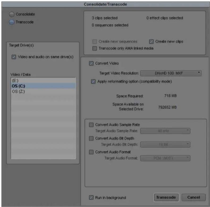
- Select Transcode, and then select Run in background, and then click Transcode.
- Select Tools > Background Queue Window.
The Background Queue Window opens and displays all current jobs.

- (Option) If you consolidate or transcode multiple clips and want to change the priority of one or more clips — for example, to transcode the most important clips first — click the Priority menu and select one of the following:
▶High Priority
▶Normal Priority
▶Low Priority

You can change the priority of your consolidate or transcode jobs at any time during the operation. Changing the priority does not affect an consolidate or transcode operation currently in progress.
Loading the Media Database
The media database is a catalog of master clips and precomputes stored on a media drive. One use of the media database by your Avid editing application is to display master clips and precomputes in the Media tool.

The information in this topic applies only to media on local drives or on unmanaged shared storage drives. The information does not apply to shared storage managed by Avid Interplay. For more information, see the Interplay documentation.
Bins contain references to media files based on the contents of the bin. Your Avid editing application does not maintain the entire database in memory at all times. Instead, it builds up a partial database for the bins that have been opened in the current session to preserve as much memory as possible for editing.
If you store the master clips and the edited sequences for a project in separate bins, you need to load the entire database to relink clips to their media files in the following two cases:
- Recapturing: When you recapture the master clips while the sequences bin is closed, quit and restart your Avid editing application, and open the sequences bin only—the sequences might appear to be offline.
- Consolidating: When you consolidate the master clips and relink them to the consolidated media while the sequences bin is closed, quit and restart your Avid editing application, and open the sequences bin only—the sequences might appear to be offline.
To update the offline sequences with the new media files:
▶Select File > Load Media Database.
Your Avid editing application loads all online master clips and precomputes.

You do not need to load the media database more than once during a single editing session because the database remains in memory until you quit your Avid editing application or restart your system.

If a bin continues to display the message “Media Offline” after loading the media database, either the media files are missing or the links have been broken. For more information, see “Relinking Media Files” on page 467.
Refreshing Media Directories
Each media folder (OMFI MediaFiles and Avid MediaFiles) includes database files for the media in that folder. The Refresh Media Directories command reexamines all the media folders (directories) on the system and determines whether any of the files are out of date and need to be rebuilt. If so, it tells your Avid editing application to rebuild the files.

The information in this section applies only to media on local drives or on unmanaged shared storage drives. The information does not apply to storages (local or shared) that are managed by Avid Interplay. For more information, see the Interplay documentation.
You should refresh the media directories after you add or remove media from the media drives. For example, after you have physically moved drives). If you physically add a drive, use the Mount All command. See “Mounting and Unmounting Drives” on page 443.

Refreshing media directories can take a long time to execute on systems that have large amounts of media online.
To refresh media directories:
▶Select File > Refresh Media Directories.
Deleting Unreferenced Clips and Media
Unlike the bin files stored in project folders, media files require considerable storage space. When you finish either a rough cut or a final version of a sequence, you can quickly free storage space by deleting the media and clips that are not referenced by the sequence. You perform this procedure only on clips selected in bins.
To quickly view remaining storage on your media drives at any time:
▶ Open the Hardware tool as described in “Using the Hardware Tool” on page 116.
To delete all unreferenced clips and media files:
- Select the sequence in the bin.
- Select Bin > Select Sources.
All source clips for the sequence are highlighted in the bin.

Motion effects are not counted as references by the sequence. If you want to keep motion effects, Ctrl+click (Windows) or Command+click (Macintosh) any motion effects to add them to the selection.
- Click the bin containing the highlighted clips to activate it.
- Select Bin > Reverse Selection.
All the clips in the bin that are not source clips for the sequence are now highlighted.
- Press the Delete key, and then click the check boxes in the Delete dialog box to select the clips or the media files to delete.
- Click OK.
The selected clips and media files are deleted.
Backing Up Media Files
The OMFI MediaFiles folders and the Avid MediaFiles folders on your media drives contain the individual media files created when you captured source material. The OMFI MediaFiles folders contain the OMF media files. The Avid MediaFiles folders contain the MXF media files.
The options for backing up media files include:
- Using the Consolidate feature, as described in “Consolidating Media” on page 449, to make copies of selected media files on a target media drive connected to the system or for transfer to another system.
- Backing up smaller projects captured at low video resolutions to a removable storage device, such as a hard drive.
- Archiving larger media files and folders to a network storage device.
- Backing up to videotape (interlaced media only). For more information, see “Archiving and Restoring Media Files to Videotape” on page 476.

For information on system archiving procedures, see your Windows documentation or Macintosh documentation.
Finding a Related Media File
The Reveal File command lets you select a clip in a bin and automatically open its related media file. This command is useful if you want to delete, move, or label the media file.
To find a related media file:
- Select the clip in a bin for which you want to find the media file.
The clip is highlighted.
- Select File > Reveal File.
The system searches all available drives, opens Windows Explorer or the folder (Macintosh), and highlights related media files.

(Windows only) If more than one file is related to the clip, a message box asks if you want to see the next file. If you click OK, you need to bring the Explorer window forward by pressing and holding the Alt key while pressing the Tab key until you select the OMFI MediaFiles folder or the Avid MediaFiles folder.
Relinking Media Files
Sometimes, after you consolidate or move material between systems, the clips or sequences lose their links to the original media files. When a clip becomes unlinked, it displays the message "Media Offline." If appropriate media exists online, you can use the Relink command to reestablish the link.

In an Avid Interplay environment, relinking through the Relink dialog box is limited to non-master clips (subclips and sequences). For more information, see “Using the Relink Dialog Box in an Avid Interplay Environment” on page 1274.
When you select subclips or sequences and select the Relink command, the system searches for master clips that contain the same material included in the selection. If you relink online media, the system searches for media clips that best match the options selected in the Relink dialog box.
You can relink master clips to appropriate media files or to source tapes with compatible rates, and you can relink based on resolution. You can also relink sequences to imported or linked AMA master clips. The system compares information such as source tape name, source file name, timecode information, and channels captured. If the search is successful, the system establishes new links to the available media files. You can instruct the system to search specific drives or all available drives.

To maintain the original capture settings for a subclip or sequence, use the Batch Capture command; do not use the Relink command.

If you relink a sequence and the bin that stores the AMA (Avid Media Access) referenced clips is closed, the media does not relink. Before you relink, open the bin of the referenced clips. For information on AMA, see “The Avid Media Access (AMA) Workflow” on page 374.
To relink master clips, subclips, or sequences:
- Select the unlinked object or objects in the bin.
- Select Clip > Relink.
The Relink dialog box opens.

3. Select options.
Option Description
Relink selected items to:
Media on drive: All Available Drives: Searches across all media drives that are online
A specific drive volume: Relinks to media on a specific media drive
Master clips Relinks master clips to the appropriate media
All other items Relinks non-master clips (sequences, subclips, group clips, and other clips) to the appropriate media
Relink only to media from the current project Restricts relinking to the current project.
Selected items in ALL open bins Allows you to select multiple clips across multiple bins.
Allow relinking to offline items Allow relinking to offline elements: Relinks to clips that are offline. All available drives are searched regardless of the setting for “Relink to media on volume.”
Relink by:
Timecode Allows you to relink to Start, Aux TC1-TC5, or Sound Timecode.
Source Name Allows you to relink to a number of relink options: Tape Name or a Source File ID, Tape Name or Source File Name, Keynumber, Name, Camroll, Labroll, Disk Label, More. Click the More option to see the list of additional column name options.
Ignore extension If selected, the system compares names and ignores extensions (for example, File1.jpeg can be relinked to File1.png)
Ignore characters after last occurrence Select this option to have the system ignore the characters in the name after the last occurrence of the text you enter.
Match case when comparing tape and source file names Makes tape name and source file name search case sensitive.
Option Description
Video Relink Parameters
Relink to: Video format of current project only: Restricts relinking to
the current video format (listed in the menu option).
Any HD video format: Restricts relinking to HD formats only. Relinking searches for any available HD formats.
Any SD video format: Restricts relinking to SD formats only. Relinking searches for any available SD formats.
Any video format: Relinks to any available high-resolution, HD and SD formats.
Relink method: Highest Quality: Relinks to the highest quality clip; for online work.
Most Compressed: Relinks to the most compressed clip; for offline work.
Specific Resolution: Relinks to clips of a specific resolution. See “Relinking by Resolution” on page 472.
Relink if quality: If you select Specific Resolution as a relink method, this
menu lets you specify the range of the relink search:
Is greater than or equal to: If the selected resolution is not available, then the nearest resolution that is better (more pixels, less compression) than the requested one and that has the closest video format (image size, field topness) is used.
Is equal to: If the selected resolution is not available, the clip is displayed in the “If no match is found” list.
Is less than or equal to: If the selected resolution is not available, then the nearest resolution that is less (fewer pixels, more compression) than the requested one and that has the closest video format (image size, field topness) is used.
Format Lets you select a target project format for relinking. The
selected format is used for quality comparison; you specify the relink format in the "Relink to" parameter.
Resolution Lets you select a target resolution for relinking. The selected
resolution is used for quality comparison; you specify the relink resolution in the “Relink method” parameter.
Option Description
| If no match is found: Use Existing Media: Your Avid editing application displays the media to which the clips are currently linked. |
| Unlink (Take Offline): Your Avid editing application unlinks the clip and displays the message Media Offline. |
| Tracks to Relink Allows you to include or exclude video, audio and/or data tracks when performing a relink operation. For example, after editing with proxies, you might want to relink your sequence to a higher resolution video without having to relink the audio. |
| Create new sequences Leaves existing sequences alone and relinks only to copies with .relinked appended to their names. This option is selected by default. |
4. Click OK.
The system searches the selected media drives, and relinks clips and sequences if possible. The system disregards audio sample rate when matching media files.
Relinking by Resolution
You can relink to clips of a specific resolution.

In an Avid Interplay environment, you can use dynamic relinking to easily switch between resolutions. For more information, see “Using MultiRez and Dynamic Relink” on page 1245.
To relink a clip by resolution:
- Select the object or objects in the bin that you want to relink.
- Select Clip > Relink.
The Relink dialog box opens. - Select Relink Method > Specific Resolution.
- Select an option from the "Relink if quality" menu.
- Select a project format from the Format menu.
- Select a resolution from the Resolution menu.
The default resolution is determined by the current Media Creation setting for Capture. See “Media Creation Settings” on page 1424. If you select a different resolution in the Relink dialog box, the Media Creation setting does not change.
- If you selected Specific Resolution as your Relink method, Select one of the following:
▶ Use Existing Media — displays the media to which the clips are currently linked
▶ Unlink (Take Offline) — unlinks the clip and displays the message Media Offline
If you are working in an offline resolution and want to capture in a higher resolution, select Unlink to ensure that you recapture all the media at the higher resolution. You can check for offline media in the Timeline by displaying offline clips in a distinct color. For more information, see “Displaying Clip Colors in the Timeline” on page 672.
- Select other Relink options as described in "Relinking Media Files" on page 467.
- Click OK.
The system searches the selected media drives, and relinks clips and sequences if possible.
Relinking to Selected Clips
You can also use the Relink command for connecting subclips or sequences to selected master clips and subclips.
To relink to selected master clips and subclips:
- Move the subclips or sequences that you want to relink into the bin containing the clips.
- Select the clips targeted for relinking.
- Select Clip > Relink.
The Relink dialog box opens.
- Select “Relink all non-master clips to selected online items” to relink related subclips or sequences to the highlighted clip in the bin.
- Click the "Relink to media on volume" menu, and select an option:
▶ Select All Available Drives to search across all media drives that are online.
▶ Select a specific drive volume if you know the location of the media or if you want to relink to media on a specific media drive.
- (Option) Select "Relink only to media from the current project."
- (Option) Select "Match case when comparing tape names."
- Click OK.
The subclips or sequences are linked to the selected clips or subclips.
Relinking Tape and File Based Media
You can relink between imported and AMA linked media and captured tape based media. Usually you can only relink between clips with the same source file name or clips with the same tape name. By selecting the “Allow relinking between tape and file media” option, the system can relink by comparing the tape name to the source file name or the source file name to the tape
name. The tape name is treated like a file name when it is compared to the source file name. For example, a clip with the tape name File1.jpg can be relinked to a clip with the source file name File1.png.
Make sure that the tape name and the source filename matches exactly, minus the file extension and the version separator, before you relink. Since some third-party transcoding applications only accept a specific file name character limit, your tape name could get changed without you realizing it when you bring the file into the Avid editing system. If you plan on relinking the file, Avid recommends you change the tape name in the third-party application (to match the tape name to the source file name) before you bring the file into the Avid editing system.
To relink tape and file based media:
- Select the sequence.
- Select Clip > Relink.
The Relink dialog box opens.
- Select "Allow relinking of Imported/AMA clips by Source File name."
- Select "Allow relinking between tape and file based media."
- Click OK.
The clips are relinked to the original media files.
Relinking Consolidated Clips
If the appropriate media exists online, you can reconnect consolidated clips, subclips, or sequences to the new or old media files.
For example, if you consolidated a sequence and forgot to create a duplicate, and later decide to use the original media files instead of the consolidated media files, you can break the new link and reestablish the old link to the original files.

Because subclips and sequences do not point directly to the media files, you can perform this procedure only by using the source master clips.
To relink consolidated subclips or sequences:
- Select the new master clips for a consolidated subclip or sequence (the clips have the file name extension .new), and unlink them.
For information on unlinking, see “Unlinking Media Files” on page 475.
- Select Clip > Relink.
The Relink dialog box opens.
- Select “Relink offline master clips to online media files” to relink master clips to media files that share similar database information.
- Click the “Relink to media on volume” menu, and select a specific drive volume that contains the original media files.
- (Option) Select "Relink only to media from the current project."
- (Option) Select "Match case when comparing tape names."
- Click OK.
The clips are relinked to the original media files.
Relinking Moved Projects
If you move projects between systems with similar media existing at each site but captured separately, your clips and sequences display the message “Media Offline.” You can use the Unlink and Relink commands to reconnect the files at either site.
For example, if you have a project that requires sharing work between two different sites, you can capture the source material once at each site and exchange only the project folder at each stage, rather than move large media drives back and forth. The project folder can be exchanged on floppy disks or instantly across a network. Because the media files maintain slightly different parameters at each site, you must relink the material each time.
Unlinking Media Files
You can use the Ctrl and Shift keys to modify the Relink command for unlinking clips from their media files.

Because subclips and sequences do not point directly to the media files, you can perform this procedure only by using the source master clips.
To unlink master clips from their current links:
- Select the master clips to unlink.
- Depending on your operating system, do one of the following:
▶(Windows) Ctrl+Shift+Right-click the clips and select Unlink.
(Macintosh) Using a multi-button mouse: Press and hold Cmd+Shift and Right-click the clips and select Unlink, or select Clip >Unlink from the main menu.
(Macintosh) Using a standard mouse: Press and hold Cmd+Ctrl+Shift and click the clips and select Unlink, or select Clip >Unlink from the main menu.
The clips are unlinked and display the message Media Offline.

To enable the Right-mouse button functionality on a multi-button mouse, see your Macintosh documentation.
- (Option) If you have similar material from different sources, you can duplicate a set of clips, unlink the duplicates, and then modify the sources of the duplicates before capturing the new source material.
For example, if you are working with multicamera material, you can capture one reel, duplicate the clips several times, unlink the duplicated clips, and rename their source tapes to batch capture the remaining reels.
Archiving and Restoring Media Files to Videotape
You can archive to videotape the source media associated with sequences, master clips, subclips, and group clips. Archiving the source media to videotape is similar to recording a digital cut, except that you can reedit the sequence after you restore it.

The archive to videotape process is not available with progressive media projects.
You can use the archiving process to:
- Archive completed projects that you can restore at a later date if you need to reedit the project.
- Provide more space on the media drives for a new project.
- Create backups of your project files.
- Move a project to another workstation.
When you archive a project, the source media files are archived to videotape, and then you save the project files. For information about saving the project files, see “Backing Up Your Project Information” on page 64. You can reconstruct your project with the archived files and your source tapes.

The media files experience generation loss when the media is archived and restored because the target videotape format might include some compression.
The archiving process divides the archive into multiple archive sequences based on the lengths of the available videotapes. The archiving to videotape process adds handles to the new clips that let you reedit the sequence after you restore the media files from the videotape.
During the archiving process, the original media is archived to videotape. Media with effects is not recorded to tape because you can easily re-create the effects after the project is recaptured. However, the handles for transition effects are included in the archive file. The final sequence can be linked to the recaptured media to recreate the project.
Each archived master clip is stamped with the archive tape name and archive timecodes during the restore process. The original source information on the master clips remains unchanged.
Archiving Media Files
Before archiving your media files to videotape, you must stripe the record tapes (record black and timecode for approximately 15 seconds after the bars and tone on the tape). For information about preparing record tapes, see “Preparing Record Tapes” on page 1059.
To archive a video project's media files:
- Set up the Digital Cut tool as follows:
a. Select Output > Digital Cut.
The Digital Cut tool opens.
b. Click the Deck Selection menu, and select a deck.
c. If the Select Tape dialog box opens, click Cancel to leave Tape Name unspecified.
d. (Option) Select the Custom Preroll option, and select the number of seconds to indicate how many seconds the tape will roll before the archiving process starts. This option overrides the Preroll setting in the Deck Settings dialog box.
- Create a new bin for the archive, and name the bin.
For example, you can name the bin Archive.
-
Duplicate the sequences and clips you want to archive.
-
Drag the appropriate duplicate sequences and clips to the Archive bin.
-
Select the clips and sequences to archive from the Archive bin by doing one of the following:
▶Select Edit > Select All to select all the clips and sequences in the bin.
▶ Ctrl+click (Windows) or Command+click (Macintosh) to select specific clips or sequences.
- Select Clip > Archive to Videotape.
The Archive to Videotape dialog box opens.

7. Select the appropriate options.
If the clips or sequences that you want to archive are not highlighted in the active bin, Archive to Videotape appears dimmed in the Clip menu.
Option Description
Archive Name Type a name for the archive in the Archive Name text box. ProjectArchive is the default name. The archive name is numbered incrementally beginning with 001 to indicate the order of the tapes.
Start Timecode Type a value in the Start Timecode text box to set the starting timecode of the archive on the videotape. By default, the start timecode is set to 01:00:00:00.
For Subclips and Sequences:
Use handles Select this option, and in the Handle Length text box type the number of additional frames you want to archive at the heads and tails of the new master clips. This option provides enough overlap for trimming and adding transition effects.
Archive entire master clips Select this option if you want to archive entire master clips.
For Sequences:
Archive all clips in a group edit Select this option if you selected a sequence that contains group clips and you want to archive the media for all the clips in the group.
8. Click OK.
The Tape Lengths dialog box opens.

The Archive Length area displays the calculated length of time required for archiving the media files. The archiving process might require more time than indicated because individual clips are not divided between tapes.
- Under the “Enter the quantity of tapes available for the archive” area, do one of the following:
▶ Type the number of blank videotapes needed for the archive next to the length of time of your blank tapes. For example, if the archive length is 2 hours and 15 minutes, and you have 30-minute videotapes, you would type 5 in the 30 Minutes text box.
▶ Type a custom tape length in the Custom text box, and type the number of available blank videotapes.
The archiving process uses the tapes in the order listed in the Tape Lengths dialog box. For example, if you type 10 in the 120 Minutes text box and 5 in the 60 Minutes text box, when you start the archive your Avid editing application prompts you for each of the ten 120-minute tapes before using the five 60-minute tapes.
- Click OK.
The Digital Cut tool opens and becomes the active window.
- Follow the instructions displayed in the message boxes to complete the archiving process.
A set of archive sequences is created in the Archive bin, and the source media is output to the videotape. One archive sequence is created for each tape. When needed, the system prompts you for another blank tape. The tapes are requested in the order that they appear in the Tape Lengths dialog box.
When the system finishes creating the archive, a message box notifies you that the process is complete.
Restoring an Archive from Videotape
Restoring an archive from videotape is similar to performing a batch capture. The archiving process creates new master clips for sequences. During the restore process, each archived master clip is stamped with the archive tape name and archive timecodes. The original source information on the master clips remains unchanged.
After restoring an archive, any links to the original master clips are broken, and only the sequence and its new master clips are linked to the newly captured media files.
To restore an archive from videotape:
- Copy the project files to the Avid Projects folder.
For information about the location of the Avid Projects folder, see “Avid Projects and Avid Users Folders” on page 46.
- Open the project in your Avid editing application.
- Open the archived bin.
- Select Tools > Capture, and set the following options in the Capture tool:
a. Click the Deck Selection menu, and select a deck.
b. If the Select Tape dialog box opens, click Cancel to leave Tape Name unspecified.
c. Click the Res (Resolution) menu, and select a resolution.
d. Click the Target Drive menu, and select a drive volume.
For more information about setting up the Capture tool, see “Setting Up the Capture Tool” on page 185.
- Select the archived sequences, original sequences, and original clips.
If you select only the archived sequences, the media is restored during the restore process, but the new media is not relinked to your original clips.
- (Option) To relink the new media to the original clips, select the original clips and repeat the restore process.
Repeating the restore process relinks only the selected items to the new media files.
- Select Clip > Restore from Videotape.
The Restore from Videotape dialog box opens.
- (Option) If you are repeating the restore process, select “Restore only those items for which media is currently unavailable.” Otherwise, deselect this option.
- Click OK.
The Capture tool becomes the active window.
- Follow the instructions displayed in the message boxes to complete the restore process.
Your Avid editing application recaptures the archived sequences and clips, and relinks the selected clips and sequences to the new master clips.
- Batch import any graphics and render all non-real-time effects.
For information about batch import, see “Reimporting Files” on page 318.
Sequence and Clip Information Summary
You can generate a report to display information about the contents of a sequence. For example, you can generate a list of the types of effects in your sequence or the location of a particular effect. You can also create a clip summary or a source summary. This allows you to display a list of clip names, tape names, offline clips, and path locations of imported clips contained in your selection.
You generate reports from the Sequence Report dialog box, which you can access from the Source monitor, the Record monitor, or directly from a sequence in a bin. The Sequence Report dialog box allows you to select your criteria and create a report that displays in a text editor. You can then search the summary for the exact information you want.
Example 1: Preparing for Online Editing
When you move your sequence from an offline system to an online system, you can run an effect summary and a source summary report. The Effect Summary displays a list of all effects, including a separate list of plug-ins used. The Source Summary lists all the tapes you need for recapture and all of the import paths for imported graphics.
Example 2: Finding Specific Effects
You use the Effect Summary and Effect Location List to find a particular effect. When you output the summary to a text editor, you can search the report to find all occurrences of the particular effect. In addition, you can type the start or end timecode value for each occurrence into the Source/Record monitor to go to the start of the effect in the Timeline. You might find this useful when you need to replace or modify a specific plug-in, for example.
Example 3: Plug-in Information
An Effect Summary displays a list of effects found in the selection, including how many times the sequence uses an effect. For plug-ins loaded on your system, a section displays a summary of the plug-ins used, displaying the name, the vendor, the version and the ID of the plug-in. This can help by providing a list of the plug-ins needed for online work.

If a plug-in is not loaded on your system when you generate the summary, if you select the option "Show Missing Effects Only" from the Sequence Report dialog box, the information displays "unavailable effect," in addition to the plug-in name, the plug-in ID (is this gone?), and other information associated with the effect. (Is the vendor and version number displayed). This is helpful when identifying the effect.
Creating a Summary of Effects and Source Information
Before you use the Sequence Report dialog box to create a summary of effects, source information, or clip information, you might want to do the following:
- Determine if you want the report to cover specific tracks or a section of the sequence between In and Out points. Loading a sequence in the Source/Record monitor before you generate a report allows you to select which part of the sequence about which you want information.
- Choose the summary options you want information on — types of effects, location of effects, source information, or clip information.

You can modify the sequence name and the starting timecode in the Sequence Report dialog box.
To generate a summary report:
- Do one of the following:
From a bin, right-click a sequence and select Sequence Report. You can select multiple sequences for generating reports.
With a sequence loaded in a monitor, right-click the monitor and select Sequence Report.
The Sequence Report dialog box opens.
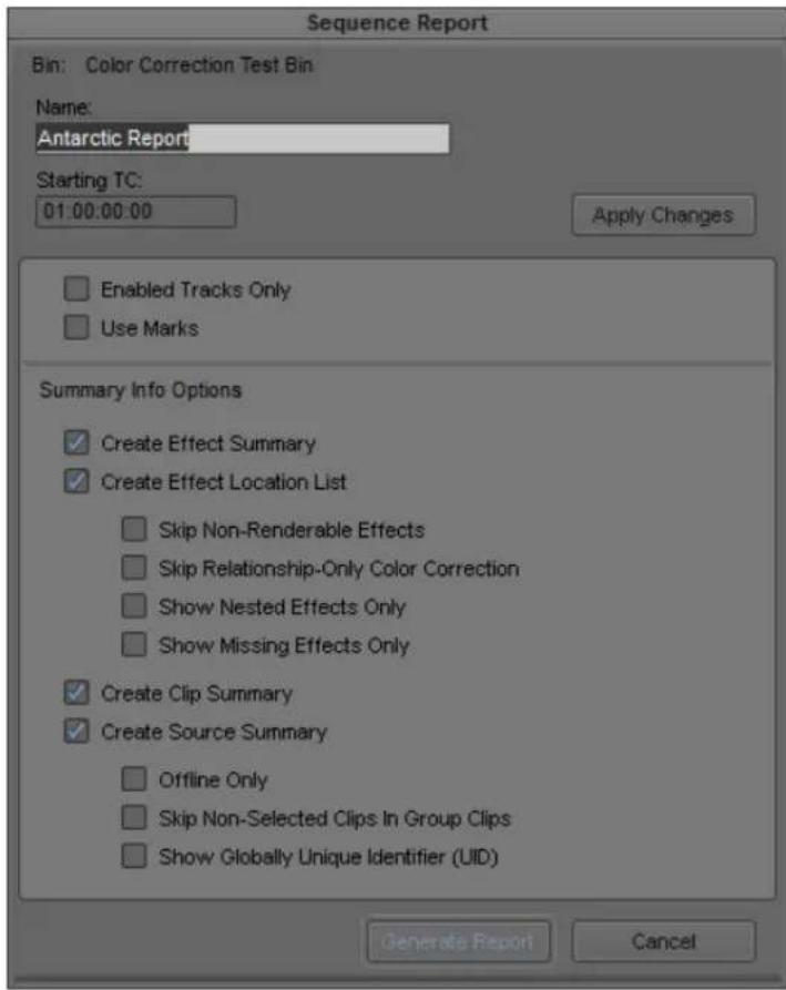
- (Option) Do the following:
▶If you selected specific tracks, click Enabled Tracks Only.
▶If you set In and Out points, click Use Marks.
If you want to run a report on the entire sequence regardless of tracks or marks, do not select either of these options.
- Select the Summary Info options you want to include in your report. For information on report options, see “Summary Information Options” on page 484.
- Click Generate Report.
The Save Summary Output File As dialog box opens.
- Use the default file name or rename the report and choose a folder to save the report to, click Save.
If you select more than 8 sequences, a dialog box asks if you want to generate sequence reports for all selected items.
The application writes the report to a text file and opens a text editor.
Summary Information Options
The following options allow you to select which information to include in the sequence report.
Summary Option Suboption Description
| Create Effect Summary | This displays the types of effects and how many were found in your sequence, the breakdown by effect type, and an effect plug-in summary. If you have selected individual tracks or selected IN and OUT points, only those effects that fall within those parameters appear. | |
| Create Effect Location List | This displays the location of an effect. Depending on the criteria you selected, this displays track, start timecode, end timecode and effect name. | |
| Skip Non-Renderable Effects | Select this option if you do not want any non-renderable effects, such as pan/volume effects, to appear in the report. | |
| Skip Relationship-Only Color Correction | Select this option if you do not want any color correction effects with only relationships to appear in the report. | |
| Show Nested Effects Only | Select this option if you want to only display the nested effects in your sequence. Effects that are nested inside of other effects show the parent effect track they are applied to with the track name in parentheses and indented to show the nesting relationship. | |
| Show Missing Effects Only | Select this option if you want to only display the plug-in effects missing from your sequence. Plug-in effects that are missing in your sequence display as “Unavailable Effect,” but also lists the type of effect and other important information which help you identify the type of effect. This option is helpful when you move your sequence to a system that does not have the plug-in installed. |
Summary Option Suboption Description
| Create Clip Summary orCreate Source Summary | Depending on the criteria you selected, a Clip Summary displays the number of clips found, type of clip, track, offline information, clip name, and clip Mob ID.A Source Summary displays the number of tape-based sources found, project name, tape name, tape ID, and tape Mob ID. It also displays a list of import paths for any imported clips, such as graphics. |
| Offline Only Select this option if you want to display offline clips and/or sources only. | |
| Skip Non-Selected Clips in Group Clips Select this option if you do not want any non-selected clips inside of a group clip to appear in the report. | |
| Show Globally Unique Identifier (UID) Select this option if you want to display the unique identifiers (Mob IDs) associated with the clips and sources in your sequence. |
12 Viewing and Marking Footage
Before you begin editing, you can review your footage, add markers and comments to clips, mark IN to OUT points, and create subclips. By viewing and marking your material in advance, you can concentrate on editing and refining your sequence at a later time without having to pause and set marks each time you load a new clip. Techniques for playing back, viewing, and subcataloging clips are described in the following topics:
- Viewing Methods
- Customizing the Composer Window and Monitors
• Using the Info Window
• Using the Timecode Window - Playing Video to the Client Monitor
- Activating and Deactivating the Client Monitor Display
- Selecting the Video Display Settings
- Playing Video to a Full-Screen Monitor
- Adjusting the Play Delay Offset
• Using the Tool Palette - Playing Selected Clips in a Loop
- Loading and Clearing Footage
- Controlling Playback
- Playing Back to a DV Device
• Video Quality Options for Playback - Setting the Video Quality for Playback
• Marking and Subcataloging Footage - Using Markers
• Finding Frames, Clips, and Bins
Viewing Methods
You can work with clips and sequences in several ways, depending on your needs and preferences. Each method has its own uses and advantages, as described in the following table:
Viewing Method Description
In bins You see pictorial images of the clips in your bins by using Frame or Script view and can play the clips in the bin. For more information, see “Using Frame View” on page 330 and “Using Script View” on page 332.
In the Source monitor You can load clips and sequences into the Source monitor to view and mark or subcatalog shots for use in a sequence that you build in the Timeline. For more information, see “Loading and Clearing Footage” on page 503.
In the Record monitor You can load a sequence into the Record monitor to view, mark, or modify an existing sequence. You can load a series of clips into the Record monitor to create an instant sequence (rough cut). For more information, see “Loading and Clearing Footage” on page 503 and “Creating an Instant Rough Cut” on page 582.
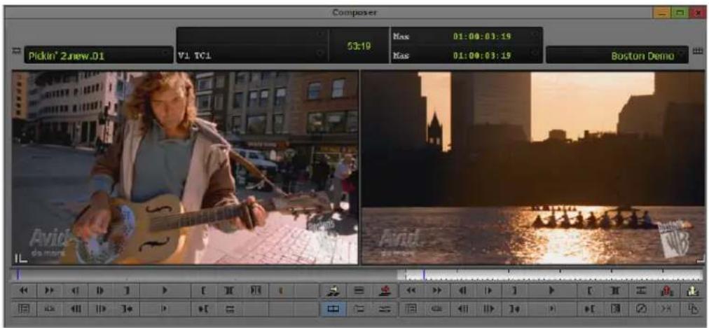
Source monitor with clip loaded (left) and Record monitor with sequence loaded (right)
In pop-up monitors You can load several clips into pop-up monitors to view and mark clips in smaller, movable windows. For more information, see “Loading and Clearing Footage” on page 503.
In the Timeline Use the Timeline to view individual tracks for either a sequence or a source clip. Click the Toggle Source/Record in Timeline button to switch between displaying the sequence tracks and the source tracks.

Timeline in Source mode for viewing tracks. Bottom: Toggle Source/Record button.
Customizing the Composer Window and Monitors
The Composer window is central to the editing process, providing all the essential controls for viewing, tracking, marking, and editing source and record footage. The Composer window includes the Source and Record monitors.
All monitors in your Avid editing application use a display aspect ratio that matches the aspect ratio for the project. For HD projects, this is always 16:9. For SD projects, it is either 4:3 or 16:9. For more information, see “Changing the Aspect Ratio for a Project” on page 597.

To view 16:9 footage on a Client monitor, you need an HD monitor or a 16:9 compatible full-screen NTSC or PAL monitor.

Composer window with monitors using 4:3 aspect ratio
Use the Composer Settings dialog box and the menus within the Composer window to configure various displays and functions. For information on all Composer settings, see “Composer Settings” on page 1367.

Illustrations of the Composer window in this chapter show two button rows, two information rows, and the Center Duration display. You can set this display on the Window tab of the Composer Settings dialog box.
Resizing the Composer Window and Monitors
You can resize the monitors that display your footage in a variety of ways. You can:
- Resize any monitor to provide more area for displaying the Timeline or other windows

If you are working with a multi-track Timeline, you might want to change the screen resolution to display more information on the screen. See your Windows or Macintosh documentation.
- Hide the Source monitor and display an enlarged Record monitor for a more detailed view of the media in your sequence
You can then use a keyboard shortcut to switch between the enlarged Record monitor and the standard size. This configuration is particularly useful during final finishing.
- Hide the video completely, leaving only the controls and information portions of the monitors visible. No video is displayed in the Composer window. Video is still displayed on the Client monitor.
- Hide the controls completely, leaving only the video visible.
- Display data above the monitor as one or two rows of data, or allow the Avid editing application to arrange the data into one or two rows as you resize the monitors.
To resize the Source and Record monitors:
Drag the lower right or lower left corner (Windows) or lower right corner (Macintosh) of the Composer window to the size you want.
If you select the Flow Data Dynamically option on the Window tab of the Composer Settings dialog box, the data above the monitors displays in either one or two rows, depending on the size of the Composer window.
To resize a pop-up monitor:
▶ Click the lower right corner of the monitor and drag it to the size you want.
To switch back to the standard-size Source/Record monitors:
▶Select Workspaces > Source/Record Editing.
To hide the Source monitor and enlarge the Record monitor:

- Press and hold the Alt key (Windows) or Option key (Macintosh) and then click the Source/Record Mode button.
Only the Record monitor is displayed in the Composer window.
- Right-click the Record monitor, and select Full Size Video.
To reduce the Record monitor to its standard size:
▶ Right-click the Record monitor, and deselect Full Size Video.
To toggle between the single Record monitor and the Source/Record monitors:

Press and hold the Alt key (Windows) or Option key (Macintosh) and then click the Source/Record Mode button.
To hide or display the video in a monitor:
▶Right-click the monitor, and select Hide Video.
The video disappears or reappears. When the video is hidden, the Hide Video command has a check mark beside it.
To hide the controls in a monitor:
- In the Settings list of the Project window, double-click Composer.
The Composer Settings dialog box opens.

- In the Button Display at Bottom region, select Off.
- Click OK.
Displaying Tracking Information
Tracking information consists of various formats used to identify clips, audio and video tracks, individual frames, or footage durations while you work. Your Avid editing application displays this information above the monitors in the Composer window and in the Timeline window.
Tracking information is updated continuously to reflect your current position in the footage. You can select which information you want to track from the Tracking Information menu (see "Tracking Format Options" on page 492).
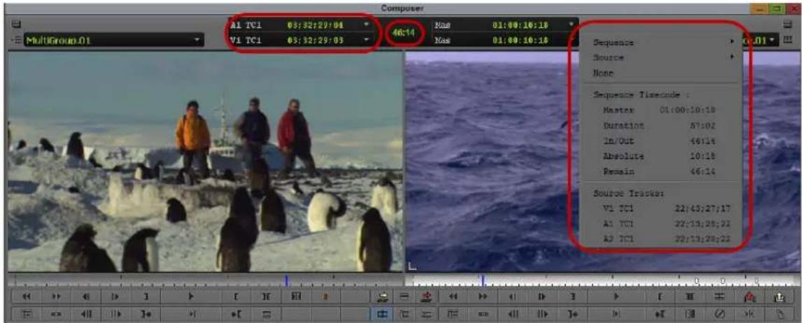
Tracking information in the Composer window. Left to right: First row of information (bottom) and second row of information (top). center duration display, and Tracking Information menu. Click anywhere in the information display area to display the Tracking Information menu.
By default, the tracking information area displays no data until you select a tracking format. There is no display of tracking data when there is no material loaded in the monitor. If you load a clip and no information is currently displayed, you can still open the menu by clicking in the area above a monitor.
To display tracking information:
- Load a clip or sequence into the monitor.
- Click in the information display area in either the first or second row of information above the monitor to open the Tracking Information menu.
- Select the type of tracking information you want to display.
If you select the option for two information rows above the monitors in the Composer settings (in the Window tab), you can display two different types of tracking information for the footage in each monitor.
For example, you can display both running timecode and IN to OUT durations for clips loaded in the Source monitor. You can display similar information for the sequence shown in the Record monitor.

To move through footage by entering timecode, make sure the top row of information displays timecode (for example, V1). For more information, see “Using Timecode to Find a Frame” on page 538.
Tracking Format Options
The Tracking Information menu contains options for information to be displayed above the monitors. The contents of the menu varies, depending on the monitor.

Examples of the three panes in the Tracking Information menu for the Source monitor (left) and for the Record monitor (right)
Panes in the Tracking Information Menu
The Tracking Information menu has three panes. You can select an option from pane 1, pane 2, or pane 3 to be displayed above a monitor. The following table describes the contents of the three panes:
Pane Description
Pane 1 Lets you select a format for the tracking information. In the Record monitor, you set select a format for either the Sequence tracking information or the Source clip tracking information. In the Source monitor, you can select a format for the Source clip tracking information only. The Sequence submenu lets you select Timecode, Footage (feet and frames for 24p and 25p projects), or Frames (a sum total of frames for either film or video).

When you are working with a 24p or 25p project, the Timecode submenu lets you select an output timecode format. The Footage submenu lets you select a supported film type. The final Timecode, Footage, and Frames submenu then displays the master timecode (Mas), duration of the entire clip (Dur), IN to OUT duration (I/O), absolute timecode (Abs), and time remaining (Rem).
The Source submenu displays the information for the tracks existing in the currently loaded clip or sequence. For example, a clip with only one audio track does not show an option for A2. The item you select is displayed above the monitor.
Pane Description (Continued)
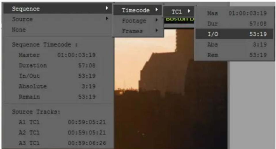
Pane 1 example when you select Sequence > Timecode > TC1

Pane 1 example when you select Source > V1
Pane 2 Lists Source or Sequence timecode options, such as master timecode (Master), duration of the entire clip (Duration), IN to OUT duration (In/Out), absolute timecode (Absolute), and time remaining (Remain). The format type that you select from pane 1 determines the tracking format that is displayed.
Pane Description (Continued)

Example of Pane 2 in the Tracking Information menu
Pane 3 Displays the timecode for the source track of a specific track (V1, A1, A2, and so on). The information is continuously updated based on the location of the position indicator.
Tracking Format Options
The following table describes the tracking format options.
Option Description
Master Displays master timecode at present location.
Duration Displays total duration of the sequence.
In/Out Displays duration between IN and OUT points.
Absolute Displays absolute time duration at present position.
Remain Displays time remaining at present position.
VI TC (or EC) Displays the source track of the video on track 1, and the timecode (or edgecode).
A1 TC (or EC) Displays the source track of the audio on track 1, and the timecode (or edgecode).
A2 TC (or EC) Displays the source track of the audio on track 2, and the timecode (or edgecode).
D1 TC1 Displays the ancillary data track and the timecode.
| Option | Description | (Continued) |
| TC1, 24, 25, 25PD, 30D, 30ND | For 24p and 25p projects only. TC1: base timecode for the project; 24: 24p project; 25: 25p project; 25PD: 25p with pulldown: 30D: 30 drop frame; 30ND: 30 non-drop frame | |
| Clip Name Displays the name of the clip. | ||
| Timecode Displays tracking information as timecode (24p and 25p projects include a submenu with the various timecodes). | ||
| Footage For 24p and 25p projects only. Displays tracking information as feet and frames. | ||
| Frames Displays tracking information as total frames. | ||
Using the Info Window
The Info window displays statistical information about clips and sequences. You can open the Info window from the Source monitor, the Record monitor, a pop-up monitor, a bin, or a Script window. The Info window updates the information automatically.
You can cut, copy, and paste information from the Info window, but you cannot edit or change any information within the window.
To display information from the Record monitor:
- Do one of the following:
▶Right-click the monitor and select Get Info.
Place the mouse pointer over the monitor and press Ctrl+I (Windows) or Command+I (Macintosh).
The Info window opens. Only fields with data are displayed.

To display information from a bin:
- Select a clip or sequence in a bin. You can use any bin view, and you can Ctrl+click to select multiple media objects.
- Do one of the following:
▶Press Ctrl+I (Windows) or Command+I (Macintosh).
▶Right-click the clip or sequence and select Get Info.
The Info window opens. Only fields with data are displayed.

If you select more than 8 media objects, a dialog box asks if you want to open information windows for all selected items.
Using the Timecode Window
Each monitor has two lines available to display timecode as described in “Displaying Tracking Information” on page 490. In addition, the Timecode window lets you display up to 48 lines of timecode in a separate window.
When you are working with a 24p or 25p project, you can display additional timecode information in the Timecode window. The output format timecodes TC 24, TC 25, TC 25P, and TC 30 are available from the Timecode menu, as are the source timecodes for clips and subclips.

You need to add the timecode track to the clip or sequence before the timecode tracking formats appear in the Timecode menu. For more information, see “Displaying Timecodes in a 24p or 25p Project” on page 350.
When displaying TC 30 source or M 30 timecodes, the pulldown phase for NTSC reference is displayed.
To set a timecode display:
- Select Tools > Timecode Window.
The Timecode window opens.
- Click anywhere in the Timecode window, and select an option.

Example of a Timecode menu
- To add an additional line of timecode, click Add Line, then click the new line and select an option.
- To change the size of the font displayed in the Timecode window, select Size > font size.
- Click the Close button to close the Timecode window.
Playing Video to the Client Monitor
You might want to see your sequences and effects as they appear on an external display monitor. To do this, connect a Client monitor to your Avid system.
There are two ways to connect a Client monitor to your Avid system:
- Through your Avid input/output hardware device
For details on connecting a Client monitor through your Avid input/output hardware, see the appropriate topic for your Avid input/output hardware device in “Connecting Cameras, Decks, and Monitors” in the Help.
- For software only-systems, through an IEEE 1394 connection, analog connection, or dual-head display board.
For details on connecting a Client monitor to a software-only system, see “Connecting the Editing Equipment.”

If you do not have a Client monitor connected, you can still view the video through the camera eyepiece or through a monitor attached to a deck when outputting to an external camera or deck.
For details on playing video to a DV device, see “Playing Back to a DV Device” on page 514.

When you display video through an external monitor, you might see less responsiveness during certain system functions, such as scrub, single-frame play, effect editing, and effect preview.
Video and audio might appear to be out of sync when you have a DV device and a Client monitor attached to your system. The system, however, is functioning normally. For more information, see “Audio and Video Sync Issues” in the Help.
If you are using the Play Length Toggle button to limit the length of the material in the Timeline, the Play button is highlighted in white. You should check the color of the Play button, and if necessary turn off the Play Length function, before an important play and review session, such as when you want to play the entire sequence to the Client monitor. For more information on the Play Length function, see “Playing a Limited Duration of a Sequence” on page 607.
Activating and Deactivating the Client Monitor Display
If your Avid editing system has an Avid input/output hardware device attached and active, you can activate or deactivate the display in your Client monitor at any time. When the display is inactive, video is not visible in the Client monitor for either playback or scrubbing. Audio playback is not affected by deactivating the Client monitor.
Deactivating the Client monitor might be useful, for example, when you are screening material for clients and you want to make an editing change. You can deactivate the Client monitor display so that the client does not see your editing work while it is in progress, then activate the display to show the finished edit.
The status of the Client monitor display does not persist between working sessions on your Avid editing application. The Client monitor display is always active when you first start your application.

You cannot activate or deactivate the Client monitor display if you are using your Avid editing application in software-only mode. If you do not have an Avid input/output hardware device attached to your system, the Toggle Client Monitor button has a gray monitor icon and is disabled. Clicking the button has no effect.
To enable or disable Client monitor display:
▶Click the Toggle Client Monitor button in the Timeline bottom toolbar.
Client monitor display becomes active or inactive.
The Toggle Client Monitor button has a blue monitor icon when the Client monitor is active, and has a black monitor icon with a red diagonal line when the Client monitor is inactive. (If the Toggle Client Monitor button has a gray monitor icon, your application is running in software-only mode and clicking the button has no effect.)


The states of the Toggle Client Monitor button. Monitor active (left), monitor inactive (center), and button disabled (Avid editing application is in software-only mode).
The Toggle Client Monitor button appears in the Play tab of the Command palette. You can use it in the Command palette, or map it to any available button location or to the keyboard. For more information, see “The Command Palette” on page 110 and “Mapping User-Selectable Buttons” on page 112.
Selecting the Video Display Settings
After you connect the camera or digital deck and Client monitor to your Avid system, you might need to modify the way your Avid editing application plays video to the Client monitor and application monitors. Use the Video Display setting in the Settings list to configure these settings.
To select Video Display settings:
- Click the Settings tab in the Project window.
The Settings list appears.
- Double-click Video Display.
The Video Display Settings dialog box opens. The options available in the Video Display Settings dialog box vary depending on the model and configuration of your Avid editing application.

- Select or modify the options for video display and click OK.

The options available vary depending on the model of your Avid editing application.
For information about all options in the dialog, see “Video Display Settings” on page 1441. Some of these settings apply to playback and how effects are processed. See the following topics:
- "Playing Back to a DV Device" on page 514
- "Video Quality Options for Playback" on page 516
- "Setting the Video Quality for Playback" on page 517
- "Options for Controlling Real-Time Effects Playback" in the Help
Playing Video to a Full-Screen Monitor
The Full Screen Playback option lets you view your video on a full-screen monitor.
To enable full screen playback:
- Make sure your system is properly set up for full-screen monitor play.
For more information, see “Understanding Full Screen Playback Options” in the Help. - Check the Full Screen Playback Settings to ensure you have them set properly.
For more information, see “Full Screen Playback Settings” on page 1407. - Select Special > Full Screen Playback.
To disable full screen playback:
▶Type Shift+Ctrl+F (Windows) or Shift+Command+F (Macintosh).
Adjusting the Play Delay Offset
Your Avid editing application uses a combination of hardware to provide for full audio and video playback capabilities. The use of an OHCI (Open Host Controller Interface) or a 1394 card to input and output DV signals along with the output to a computer's desktop monitor and consumer audio chip could present playback sync issues.
If you do have 1394 selected from the Device menu, the Desktop Play Delay option lets you adjust the offset between audio and video playback on the Avid system.
With a camera or transcoder connected to your system, when you play a sequence in the Timeline and the Composer (desktop) monitor plays back video and audio ahead of the camera or transcoder, you can adjust this offset. Playback on the Composer monitor can be delayed by the number of frames chosen as an offset so that the video and audio play simultaneously to the camera or transcoder and the Composer monitor.
To adjust the offset:
- In the Project window, click the Settings tab.
The Settings list appears. - Double-click Desktop Play Delay.
The Desktop Play Delay dialog box opens. - Click the Desktop Play Delay slider to increase or decrease the amount of frame offset.
You might need to readjust the frames a few times to find the correct offset.
Using the Tool Palette
The Tool palette provides additional buttons for editing and navigating with your Avid editing application. The Tool palette buttons can appear with or without labels, and you can “tear off” the Tool palette to display it in another screen location.
You can also map other functions and buttons to the Tool palette for easy access. See “The Command Palette” on page 110.
To use the Tool palette:

- Click the Fast Menu button in the Composer window or on a pop-up monitor.
The Tool palette opens.
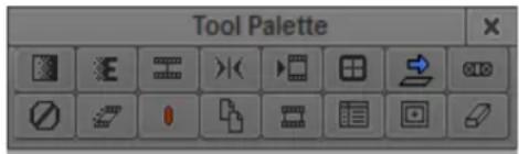
- Click a button in the Tool palette.
Your Avid editing application performs the function associated with the button.
To leave the Tool palette open and move it to another location:
- Click the Fast Menu button in the Composer window or on a pop-up monitor.
- Click the location where you want the Tool palette to be displayed.
- (Option) If a subset of the buttons appears in the Tool palette, click the lower right corner and drag it to the right and down to reveal the full Tool palette.
To view the names of the buttons in the Tool palette:
▶Move the pointer over a button.
The name of the button appears in a ToolTip box.
To display labels on the Tool palette buttons:
- In the Project window, double-click the Interface Setting.
The Interface Setting dialog box appears.
- Select Show Labels in Tool Palette.
- Click OK.
Labels appear on the buttons under the icons.
Playing Selected Clips in a Loop
You can view several clips one after another in a continuous loop by selecting Bin > Loop Selected Clips. This feature is useful if you want to view several versions of the same scene. While playing the loop, you can jump to the next clip by pressing the Tab key or jump to the previous clip by pressing Shift+Tab.
To play several clips in a continuous loop:
- Select the clips in the bin that you want to play in a loop.
-
Select Bin > Loop Selected Clips.
The clips begin playing in the Source monitor from the IN point to the OUT point. -
Press the space bar to stop the play loop.
If you want to play the clips from start to end, press the Alt key (Windows) or the Option key (Macintosh) while performing this procedure.
Loading and Clearing Footage
You can use several methods to load individual or multiple clips or sequences into monitors. You can also use the Clip Name menus to display or clear clips and sequences from the monitors.

You can adjust settings to optimize playback performance in the monitors. For more information, see “Video Quality Options for Playback” on page 516 and “Setting the Video Quality for Playback” on page 517.

If a sequence that was created in an older version of an Avid editing application contains effects or color corrections, you might need to update the sequence. If a sequence requires updating, the Update Sequence dialog box might open when you load the sequence. For more information, see “Updating and Reverting Existing Effects in Sequences” in the Help.
Loading Clips or Sequences into Monitors
To load clips or sequences into a monitor:

- Click the Source/Record Mode button to enter Source/Record mode.
- Open a bin and do one of the following:
▶Locate a single clip or sequence.
▶Select multiple clips or sequences.
For more information, see “Selecting Clips and Sequences” on page 335.
- Do one of the following:
▶Double-click the single clip or sequence, or any one of the selected set of clips or sequences.
By default, the material opens in the Source or Record monitor. If you have the “Double-click loads clip in” option in the Bin Settings dialog box set to “New Pop-up Monitor,” the material opens in a pop-up monitor. For more information, see “Bin Settings” on page 1360.
Alt+double-click (Windows) or Option+double-click (Macintosh) the single clip or sequence, or any one of the selected set of clips or sequences.
By default, the material opens in a pop-up monitor. If you have the “Double-click loads clip in” option in the Bin Settings dialog box set to “New Pop-up Monitor,” the material opens in the Source or Record monitor. For more information, see “Bin Settings” on page 1360.
Drag the single clip or sequence, or the selected set of clips or sequences, into the Source monitor or the Record monitor.
Alt-drag (Windows) or Option-drag (Macintosh) a single clip into the Record monitor. The clip will appear at the position of the position indicator in the Record monitor.

You can also load a series of clips into the Record monitor to create an instant sequence (rough cut) by pressing and holding the Alt key (Windows) or Option key (Macintosh) while dragging the clips from the bin to the Record monitor. For more information, see “Creating an Instant Rough Cut” on page 582.
Switching Between Loaded Clips
When you have loaded multiple clips or multiple sequences into the monitor, you will see only one clip displayed at a time. You can view an alphabetical list of the loaded clips and select an alternate clip for viewing in the Clip Name menu located above the monitor.

If you press and hold the Alt key (Windows) or Option key (Macintosh) while dragging multiple clips into the Record monitor, they appear as one sequence in the Clip Name menu. For more information, see “Creating an Instant Rough Cut” on page 582.
To switch between clips:
- Click the name of the current clip or sequence displayed above the monitor to reveal the Clip Name menu.
The list in the lower portion of the menu contains a list of all the clips or sequences currently loaded in the monitor.

- Select a different clip name from the menu.
The selected clip replaces the current clip in the monitor display.

To see the list of clips or sequences sorted in the order in which they were loaded into the monitor, press the Alt key (Windows) or Option key (Macintosh) while opening the menu.
Clearing Clips from Monitors
You can use the Clip Name menu located above each monitor to clear clips from a monitor. There are two options for clearing clips:
- Remove the displayed clip and leave the monitor black but keep the clip loaded.
- Remove all the clip names from the Clip Name menu, and leave only the displayed clip loaded.
To clear the monitor or the clip or sequence names from the menu:
- Click the name of the clip or sequence currently displayed above the monitor to reveal the Clip Name menu.
- Select one of the following commands:
Command Description
Clear Monitor Removes the displayed clip or sequence from the screen, leaving black. The clips or sequences are still loaded.
Clear Menu Deletes the list of all loaded clip or sequence names and leaves only the clip currently displayed.
Controlling Playback
There are several ways to play, view, and cue clip and sequences:
- Instantly access frames or move through footage by using the position indicator within the position bar under the monitors.
- Play, step (jog), or shuttle through footage by using user-selectable buttons.
- Play, step, or shuttle by using keyboard equivalents.
- Step or shuttle by using the mouse.
You can use the methods to control clips or sequences loaded in monitors, or to play clips and sequences in the bin while in Frame view and Script view.

When viewing sequences in the Source monitor or the Record monitor, you can play only video and audio tracks that are currently monitored in the Track Selector panel. For more information, see “Understanding the Track Selector Panel” on page 707.

If you try to play a sequence and the outline of the monitor flashes, another window is covering the monitor. Click the monitor to bring it forward, or move the window that is covering it.
Using Position Bars and Position Indicators
You can quickly access frames or move within loaded footage by using the position indicators that appear in the position bars under the monitors (and in the Timeline when you are viewing a sequence). The position bars represent the length of the clip or sequence, and the position indicator marks your current position in the clip or sequence.
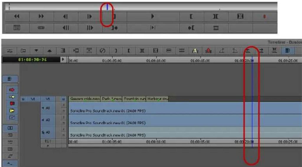
Blue position indicator in the monitor position bar (top) and in the Timeline (bottom), with the Timeline ruler above the Timeline.
To move the position indicator in the Timeline, do one of the following:
- Disable the segment tools (Lift/Overwrite and Extract/Splice-in) and click an area of the segment outside of the active trim region.
- Use the Timeline ruler.
By default, if you drag the position indicator (or scrub) through the Timeline, the media in the monitor updates quickly and smoothly. However, you do not see markers such as the start-of-clip and end-of-clip marks, sawtooth marks for In and Out points, and markers. To find a particular point of interest without viewing markers, use one of the approaches listed in the following procedure. For example, to snap to an In point in the Timeline, hold down the Ctrl key and drag the position indicator toward the In point until it stops. The position indicator will be aligned with the In point in the Timeline and the monitor displays the frame marked by the In point.
To access frames in or move through loaded footage, do one of the following:
- If you want to use the position indicator in the Timeline to view footage, do one of the following:
▶ Deselect the segment tools on the Timeline palette, or click the Smart tool toggle bar to deselect all edit tools on the Timeline palette.
▶ Position the mouse pointer over the Timeline ruler or the Timecode (TC1) track to move through the sequence.
- Depending on which frames in your sequence you want to access, do the following:
To move the position indicator and access the frame at the new position, click anywhere in a monitor's position bar or in the Timeline, or drag the position indicator to the left or right in a monitor's position bar or in the Timeline.
The speed with which you drag the position indicator determines the speed at which you move through the footage.
To go directly to the beginning or end of a clip or sequence, click to the far left or far right of the position bar or the Timeline.
To snap to the nearest transition, edit mark, marker, or audio keyframe, Ctrl-click (Windows) or Command-click (Macintosh) between the position indicator and that transition, mark, marker, or keyframe, or Ctrl-drag (Windows) or Command-drag (Macintosh) the position indicator toward that transition, mark, marker, or audio keyframe.
To snap to the last frame before the nearest transition, edit mark, marker, or audio keyframe, Ctrl+Alt-click (Windows) or Command+Option-click (Macintosh) between the position indicator and that transition, mark, marker, or keyframe, or Ctrl+Alt-drag (Windows) or Command+Option-drag (Macintosh) the position indicator toward that transition, mark, marker, or audio keyframe.
You can select the Use Fast Scrub setting to always display markers while scrubbing; however, with this option selected, the media in the monitor might update more slowly.
To display markers when scrubbing:
▶In the Settings list, double-click Timeline and deselect Use Fast Scrub.
When the Fast Scrub option is selected in an HD project, some effects are not displayed. Deselect this option to view all effects.

You can create a Timeline setting that has this option deselected and then easily switch between the settings. For information on duplicating settings, see “Duplicating Settings” on page 1342.
Playback Control Buttons
You can use the buttons that appear below the Source and Record monitors and in the pop-up monitors to play and step through your footage.
You can also use additional buttons available in the Command palette to control playback. You can remap Command palette buttons onto some existing button locations (for example, in the Tool palette) or to the keyboard. For more information about mapping user-selectable buttons, see “Understanding Button Mapping” on page 110.
The following table describes the common playback control buttons:
Button Primary Default Location Function

Play Monitors Plays the footage at normal speed. Changes to
the Stop button when playback is taking place.

Stop Play tab in Command palette Stops playback. Changes to the Play button
when you have stopped playback.

Pause button Play tab in Command palette Pauses playback.

Play Reverse button Play tab in Command palette Plays the footage backward at normal speed.

Fast Forward button Monitors Cues the footage to the next transition in the sequence.

Rewind button Monitors Cues the footage to the previous transition in the sequence.

By default, the Fast Forward and Rewind buttons cue footage to the head frame of the next transition. You can customize their behavior by selecting other alternatives from the FF/REW tab of the Composer Settings dialog box. For more information, see Composer Settings: FF/REW Tab.

Play Standby button Play tab in Command palette Places play in standby mode to prepare for playback. This is especially useful for long sequences.
To play in standby mode:
- Click the Play Standby button.
The button under the Source or Record monitor blinks yellow.
- Click anywhere to play the sequence.

Step Backward Monitors Moves the footage one frame backward.
button
- Press and hold the Alt key (Windows) or Option key (Macintosh) while clicking the button to move 10 frames (NTSC and PAL) or 8 frames (24p) backward.

Step Forward button Monitors Moves the footage one frame forward.
- Press and hold the Alt key (Windows) or Option key (Macintosh) while clicking the button to move 10 frames (NTSC and PAL) or 8 frames (24p) forward.
| Button Primary Default Location Function (Continued) | ||
| Step Backward10-frames or8-frames button | Move tab in Command palette Moves the footage 10 frames backward (NTSC or PAL) or 8 frames backward (progressive formats). | |
| Step Forward10-frames or8-frames button | Move tab in Command palette Moves the footage 10 frames forward (NTSC or PAL) or 8 frames forward (progressive formats). | |
| Step Backward OneField button | Move tab in Command palette Moves the footage one field backward in field-based media. For more information, see “Stepping Forward and Backward by Field” on page 510. | |
| Step Forward OneField button | Move tab in Command palette Moves the footage one field forward in field-based media. For more information, see “Stepping Forward and Backward by Field” on page 510. | |
Stepping Forward and Backward by Field
You can locate defects on individual fields of a frame with the single-field step feature.

The single-field step feature is not available when you work with progressive formats.
By default, your Avid editing application displays the first field of every frame when you step through material. With single-field step, you can view both fields of each two-field frame sequentially to locate a dropout from the source videotape or dust and scratches from the original film footage.
To use single-field step:
- Click the Step Forward One Field button or the Step Backward One Field button.
A number 2 displays in the upper right corner of the monitor to indicate you are parked on field 2 of a frame. (The absence of the number 2 indicates you are parked on field 1 of the frame.) Subsequent single-frame steps are based on this field.
- Continue to click the Step Forward One Field or Step Backward One Field button to view each field of a frame.

To return to viewing only field 1 of each frame, make sure you park on field 1 of a frame before using the Step Forward or Step Backward buttons.

Any edits you make using the paint tools affect both field 1 and field 2 of each frame.
Playback Control Using the Keyboard
Many playback functions, including most of the playback controls covered in “Playback Control Buttons” on page 508, are mapped to keys on your keyboard. You can customize the keyboard by mapping buttons or menu commands to it from the Command palette, for example to add other playback functions.
Default keyboard mappings vary, depending on the type of keyboard attached to your Avid system. The information in this topic describes default keyboard mappings for playback control for a keyboard used in the United States. If an Avid-supported international keyboard is attached to your Avid system, the default keyboard mappings match that keyboard.
For more information on keyboard settings and keyboard mapping, see the following topics:
- “Understanding Button Mapping” on page 110
- “Using Foreign Keyboard Mapping (Windows)” on page 1546
- “Keyboard Settings” on page 1422
The following table describes the default keyboard mappings for basic playback control for a keyboard used in the United States:
Keys Function
natural_image
Abstract diagram with three gray blocks and directional arrows, no text or symbols present- Left quote or tilde Start and stop playback key (above Tab key)
- T a b k e y
• 5 k e y - Space bar

1, 2, 3, and 4 keys • 1 key—moves the footage 10 frames backward (NTSC or PAL) or 8 frames backward (progressive formats)
- 2 key—moves the footage 10 frames forward (NTSC or PAL) or 8 frames backward (progressive formats)
- 3 key—moves the footage 1 frame backward
- 4 key—moves the footage 1 frame forward
Keys Function

Home, End, Left Arrow, and Right Arrow keys
• Home key—move to the beginning of a clip or sequence
• End key—move to the end of a clip or sequence
- Left Arrow key—moves the footage 1 frame backward
- Right Arrow key—moves the footage 1 frame forward
J, K, and L keys Let you play, step, and shuttle through footage at varying speeds. For more information, see “Playing Footage with the J-K-L Keys (Three-Button Play)” on page 512
Playing Footage with the J-K-L Keys (Three-Button Play)
The J-K-L keys on the keyboard let you play, step, and shuttle through footage at varying speeds. This feature, also referred to as three-button or variable-speed play, lets you use three fingers to manipulate the speed of playback for greater control.
You can also use the J-K-L keys to perform smooth audio scrubbing of selected tracks. For more information, see “Performing Smooth Audio Scrub” on page 770.
To shuttle through the footage using the J-K-L keys on the keyboard:
- Do one of the following:
▶ Load a clip or sequence into the Source or Record monitor.
▶Open a pop-up monitor.
▶Select a clip in a bin in Frame view.
- Use the following keys to shuttle at varying speeds:
▶ Press the L key to move forward through the footage at normal speed.
▶ Press the L key multiple times to move forward through the footage at faster speeds, as described in the following table:
Press the L Key To Play Footage at NTSC Rate PAL Rate 24p Rate
| 2 times 2x normal speed 60 fps | 50 fps | 48 fps |
| 3 times 3x normal speed 90 fps | 75 fps | 72 fps |
| 4 times 5x normal speed 150 fps | 125 fps | 120 fps |
Press the L Key To Play Footage at NTSC Rate PAL Rate 24p Rate
5 times 8x normal speed 240 fps 200 fps 192 fps
▶ Press the J key to move backward at the same shuttle speed increments.
▶ Press the K and L keys together for slow forward (8 fps for NTSC, 6 fps for PAL, and 6 fps for 24p projects).
▶Press the K and J keys together for slow backward.
▶Press and hold the K key and tap the L key or the J key to step through footage one frame at a time.
To slow or change play direction one speed at a time:
▶Press Alt (Windows) or Option (Macintosh) while you tap the J or L key.
Play slows or changes direction one speed at a time from the speed at which you are currently playing.

For example, you are shuttling backward with the J key at 2x normal speed. Press and hold Alt and tap the L key once. Play slows to backward at normal speed (1x speed). Hold Alt (Windows) or Option (Macintosh) and tap L once again. Play stops. Continue to hold Alt (Windows) or Option (Macintosh) and tap L once again. Play goes forward at normal speed. Continue to hold Alt (Windows) or Option (Macintosh) and tap L once again. Play goes forward at 2x normal speed. Continue to hold Alt (Windows) or Option (Macintosh) and tap L once again; play goes forward at 3x normal speed. Release the keys to continue playing forward at 3x normal speed.
To pause shuttling:
▶Press the K key.
To stop shuttling:
▶Press the space bar.
Using the Mouse for Playback
You can use the mouse for one-handed control of playback. You can either jog or shuttle by using the mouse.

This applies to an Avid editing system with an Avid Nitris DX attached.
To jog or shuttle by using the mouse:
- Do one of the following:
▶ Load a clip or sequence into the Source or Record monitor.
▶Open a pop-up monitor.
▶Select a clip in a bin in Frame view.
- Do one of the following:
▶Press the N key to activate mouse control for jogging.
▶ Press the semicolon (;) key to activate mouse control for shuttling.
▶ Click the Mouse Jog button, which is available in the Play tab of the Command palette and can be mapped to any button under the Record monitor.
Click the Mouse Shuttle button, which is available in the Play tab of the Command palette and can be mapped to an editing button under the Record monitor.
- Move the mouse to the right to jog or play forward or to the left to jog or play backward.
To pause shuttling with the mouse:
▶Click the mouse button.
To quit jogging or shuttling with the mouse:
▶Double-click the mouse button or press the space bar.
You can also use the keyboard in conjunction with the mouse to control shuttling. For example, if you are shuttling with the mouse and you press the L key, the playback speeds up to the next normal play rate (30, 60, 90, 150, or 240 fps for NTSC; 25, 50, 75, 125, or 200 fps for PAL; 24, 48, 72, 120, or 192 fps for 24p projects). You can continue to change the shuttle speed and direction with the mouse.
Playing Back to a DV Device
If you do not have Avid input/output hardware attached to your system (software-only), you can play back DV media through a DV device.
Your options for playback of media to a DV device vary, depending on whether the media is played back as DV 25, DV 50, or DVCPRO HD (DV 100).
- You can play back DV 25 media through a DV device attached to a 1394 port on your computer..
- You can play back DV 50 or DVCPRO HD media through a 1394 port on your computer.


When you are playing back to a DV device, you have the option of enabling real-time encoding of effects and mixed resolutions.
To play back to a DV device connected through a 1394 port:

- Right-click the Video Quality Menu button and select Output to DV Device.
Playback to the DV device and playback to the desktop occur simultaneously.

If you do not have a device connected to a 1394 port, these options are grayed out.
- Right-click the Video Quality Menu button, select Format, and then select the native format to be sent to the DV device:
Format Availability
DV 25 411 Enabled in any SD project
DV 25 420 Enabled only in PAL SD projects
DV 50 Enabled in any SD project
DVCPRO HD Enabled only in HD 720p 59.94, 1080i 50, and 1080i 59.94 projects
- (Option) If you are in an SD project, right-click the Video Quality Menu button, and then select Realtime Encoding.
- If you select Realtime Encoding, you are in real-time effects mode. The media in your sequence is encoded to the format selected in the Video Quality menu. Enabling Realtime Encoding is helpful if you have a faster processor because it lets you bypass rendering many of your effects to disk.
- If you do not select Realtime Encoding, you are in native play mode. You must render all effects and any media not matching the selected format will be played as black. The Video Quality menu only lets you select Full Quality (green) playback. Disabling Realtime Encoding is helpful if your machine has a slower processor.
- Select Realtime Encoding to output 24p media to a DV device. You must also select Full Quality playback.

Realtime Encoding applies only to playing DV 25 and DV 50 media to a DV device.
You can also select the DV playback options in the Video Display Settings dialog box.
Video Quality Options for Playback
Your Avid editing application provides a range of video quality options for playback. Depending on your system configuration and the complexity of your sequence, you might need to switch to a lower quality option to avoid missing frames or choppy video during real-time playback.
The options available vary depending on your attached hardware. Some third party hardware might not support Draft Quality and Best Performance options.
The options are also different when you are working in MultiCamera Mode. For more information, see “Real-time Playback in MultiCamera Mode” on page 1300.
Your Avid editing application can only play back interlaced stereoscopic material using one of the Full Quality options. When you are working with interlaced stereoscopic material, other options are not available.
Your Avid editing application also provides an option that improves image quality during playback of mixed-format sequences where material requires resizing. You might need to deselect this option to avoid missing frames or choppy video during real-time playback.
The first of the following tables describes the video quality options. The second of the following tables lists the options available for each configuration.
Video Quality Name and Icon Description
| Full Quality | Processes and plays the full image raster for the project. Uses a bit depth of 8 bits.This option provides the highest video playback quality by processing every image pixel. In interlaced projects, this option processes the full width of every line in both fields. In progressive projects, this option processes the full width of every scan line. |
| Full Quality 10-bit | Processes and plays the full image raster for the project, as described for Full Quality in the previous row. However, this option uses a bit depth of 10 bits, which provides higher quality processing for some effects. For more information, see the “Change the Bit Depth for Effects Processing” section in “Options for Controlling Real-Time Effects Playback” in the Help. |
| DNxHD Native Processes and plays the full image raster of DNxHD native media only. This option does not process any effects in the sequence or any media that is not DNxHD encoded. Non-DNxHD media is replaced by black frames. | |
| Draft Quality | Processes and plays a subsample of the full image raster for the project that uses 1/4 of the image information. Uses a bit depth of 8 bits. |
| This option subsamples 50% of the raster width. For interlaced projects, this option uses one field. For progressive projects, this option uses 50% of the scan lines. | |
| Best Performance | Processes and plays a subsample of the full image raster for the project that uses 1/16 of the image information. Uses a bit depth of 8 bits. |
| This option subsamples 25% of the raster width. For interlaced projects, this option uses 50% of the lines in one field. For progressive projects, this option uses 25% of the scan lines. | |
| Configuration | Available Options(single camera editing) | Available Options(MultiCamera Mode) |
| Software-only(no input/output hardware) | Full Quality | Draft Quality (SD and HD) |
| Draft Quality | Best Performance (SD and HD) | |
| Best Performance | ||
| Avid Mojo DX, Avid Nitris DX Full Quality 10-bit | Draft Quality (SD and HD) | |
| Best Performance (HD only) | ||

For information about video quality and effects processing, see “Playing Effects Back at Different Video Qualities” in the Help.
Setting the Video Quality for Playback
To set the video quality for playback:
- Do one of the following:
Click the Video Quality Menu button to cycle through the video quality options available until the button icon indicates the video quality you want.
▶ Right-click the Video Quality Menu button, and select a video quality option.
For detailed information on the video quality options, see “Video Quality Options for Playback” on page 516.
- (Option) Right-click the Video Quality Menu button, and select Video Display Settings.
This opens the Video Display Settings dialog box and lets you select additional video display settings.
For information about the Video Display settings, see “Selecting the Video Display Settings” on page 499 and “Video Display Settings” on page 1441.
Marking and Subcataloging Footage
You can speed the editing process by marking clips with IN and OUT points, by subcataloging using markers, and by creating subclips. When subcataloging, you might want to create or open additional bins for storing and isolating specific subclips, marked clips, or sequences, as described in “Using the Bins Tab” on page 72.
Marking IN and OUT Points
You can mark IN and OUT points in your footage to indicate selected material, for example, the portion of a clip that you want to edit into a sequence. You can also easily clear or move these marks.
You can mark IN and OUT points for your clips while in the bin, which provides several advantages:
• You can quickly build a sequence by splicing the marked clips into place one after another.
- You can use the process of rough-cut or storyboard editing, which lets you instantly splice several prepared clips into a sequence, as described in “Creating an Instant Rough Cut” on page 582.
- You can play back and mark clips in the bin before loading a single clip, saving several steps. Use Frame view or Script view to play back and mark clips in a bin.
Even if your marks are not accurate now, your Avid editing application lets you trim the edit points and fine-tune the sequence later without reediting the material.
To mark IN and OUT points:
- Load a clip or sequence from a bin into a monitor, or select a clip in the bin (Frame view or Script view).
- Play, step, or shuttle through the material. Use the J-K-L keys when playing a clip in a bin (Frame view or Script view).
For more information on the J-K-L keys, see “Playing Footage with the J-K-L Keys (Three-Button Play)” on page 512. - Mark an IN point by doing one of the following:
]
Click the Mark IN button under the monitor to mark an IN point and stop playback.
▶Press the Mark IN key when marking a clip in a bin. (The Mark IN key does not stop playback.)
By default on United States keyboards, the Mark IN key is the I key.
In the monitor, a Sawtooth icon appears on the left to indicate the mark IN frame.

Sawtooth icon in the frame, and marked IN point, in the monitor
- Continue moving through the material.
- Mark an OUT point by doing one of the following:
▶Click the Mark OUT button under the monitor to mark an OUT point and stop playback.
▶Press the Mark OUT key when marking a clip in a bin.
By default on United States keyboards, the Mark OUT key is the O key.
In the monitor, a Sawtooth icon appears on the right to indicate the mark OUT frame.
To clear the IN point, do one of the following:
1
▶Click the Clear IN Mark button.
▶Press the Clear IN Mark key.
To clear the OUT point, do one of the following:
C
▶Click the Clear OUT Mark button.
▶Press the Clear OUT Mark key.
To clear both the IN and OUT points:

▶Click the Clear Both Marks button.
▶Press the Clear Both Marks key.
To set a new IN point:

▶Click the Mark IN button or press the Mark IN key when you reach a different frame.
To set a new OUT point:

Click the Mark OUT button or press the Mark OUT key when you reach a different frame.
To move a mark icon:
▶Press the Alt key (Windows) or the Option key (Macintosh), drag the mark icon to a new location, and release the mouse button.
Marking an Entire Clip or Segment
Use the Mark Clip button to select an entire clip or an entire segment from a sequence. (A segment in a sequence consists of the material between any two edit points.) The Mark Clip button chooses a segment between the first set of edit lines that line up on all the selected tracks.

To ignore the current track selection and mark the material between the two nearest edit points at the current position in the sequence, press and hold the Alt key (Windows) or Option key (Macintosh) while you click the Mark Clip button.
To mark an entire clip or segment:
- Load a clip or sequence into a monitor.
- In a sequence, move the position indicator to the segment that you want to mark.
- In the Track Selector panel in the Timeline, select the tracks corresponding to the cuts you want to mark.
For more information, see “Understanding the Track Selector Panel” on page 707. - Click the Mark Clip button.

Creating Subclips
When you mark footage with IN and OUT points, either you can save the entire clip along with the new marks, or you can create subclips based on the marks you set to break up longer master clips into smaller segments of selected footage. This procedure is similar to creating a pull reel of the selects or circle takes of your best footage before editing.
Subclips do not directly reference the original media. Subclips remain linked to the master clips from which they are created, and the master clips, in turn, reference the captured media files located on your media drives. As a result, none of the original footage is lost.
In most projects, subclips do not limit your access to the original, captured master clip material when trimming. Therefore, if you must trim beyond the marked IN to OUT boundaries of the subclip to make it longer or shorter, your Avid editing application accommodates the boundary adjustments during the trim.
However, when subclips are created in 24p or 25p projects, they are always created as “hard” subclips, and you cannot trim past the edges of the subclip when adjusting transitions and edits. Hard subclips prevent film tracking information errors for editing and cut lists.
New subclips appear in bins with a distinct subclip icon and with a numbered .Sub file name extension.

A subclip in Text view in the bin
To create subclips:
- Load a clip into a monitor and mark the material from which you want to create the subclip. For more information, see “Marking IN and OUT Points” on page 518.
- Do one of the following:
▶ Press and hold the Alt key (Windows) or Option key (Macintosh), and then drag the picture from the monitor to the bin in which you want to store the subclip.
Click the Create Subclip icon, located above and to the side of the Source monitor, and drag it to the bin in which you want to store the subclip.

Create Subclip icon in the monitor
The Create Subclip icon changes to an icon of a hand pointing at a frame during the drag, and then becomes a Subclip icon when you release the frame in the intended bin.

▶Click the Make Subclip button in the Edit tab of the Command palette.
Your Avid editing application creates the subclip and places it in the active bin.
▶ Press the Alt key (Windows) or the Option key (Macintosh) while you click the Make Subclip button.
Your Avid editing application creates the subclip and opens a dialog box that lets you select the destination bin for the subclip.
Creating Subsequences
You can use IN and OUT marks to create a new, shorter sequence from an existing sequence. This subsequence becomes an independent sequence and you can edit it in the same way you edit any other sequence.
To create a subsequence:

Click the Create Subsequence icon located above and to the side of the Record monitor, and drag it to the bin in which you want to store the subsequence.
The new subsequence appears in the bin, with a numbered .Sub file name extension.
Subclips and Audio Sync for 24p and 25p Projects
Your Avid editing application allows for the 14 -frame resyncing of audio in the event of telecine errors or for the purpose of adjusting audio sync for intended online mixing, but this subframe syncing can be done only to subclips. Avid recommends that you create subclips after you capture your footage and audio but before you begin editing in order to check or adjust audio sync. It is easier to adjust the subclip's audio sync before you work the subclip into an edit. For more information about adjusting audio sync, see “Resyncing Subframe Audio” on page 619.
Marking Audio Clips
You can mark audio and video separately for an edit by using the Audio Mark buttons. This feature is useful for creating an overlap edit for an audio clip.
You can map the Audio Mark buttons from the Edit tab of the Command palette. For information on mapping buttons, see “Understanding Button Mapping” on page 110.
To mark IN and OUT points on audio tracks:
- Load a clip or sequence into a monitor.
- In the Track Selector panel in the Timeline, select the tracks corresponding to the cuts you want to mark.
For more information, see "Understanding the Track Selector Panel" on page 707.
- Move the position indicator to the location where you want to mark the audio clip.
- Do one of the following:
▶Click the Audio Mark IN button to mark an IN point.
▶Click the Audio Mark OUT button to mark an OUT point.
The Audio Marks appear in the Timeline and in the position bar beneath the monitors.


Audio Mark IN and Mark OUT marks in the position bar
To remove audio IN and OUT points:
▶Shift+click the Clear IN Mark, Clear OUT Mark, or Clear Both Marks button.

Using Markers
Markers are a type of electronic bookmark. They let you find and identify specific frames during editing. Keywords that you enter in the comments attached to a marker let you use standard Find procedures to call up the clips quickly. You can display information about the markers using the Markers window. For more information about the Markers window, see “Using the Markers Window” on page 531.
There are eight Add Marker buttons in the More tab of the Command palette. Each Add Marker button is a different color, which lets you group markers by color. For example, you can use the red Add Marker button to identify color correction frames and use the blue Add Marker button to identify cutaway shots.
You can map Add Marker buttons, as described in "Understanding Button Mapping" on page 110.
Suggested Uses for Markers
The following table describes some possible uses for markers and the Markers window:
Use Description
| Color correction notations | Use markers to mark clips or specify frames that require color correction, noting the specific correction to perform if someone else does the job. |
| Visual track alignments | Use markers at matching points in synchronized audio and video tracks so that if the tracks lose sync, you can visually realign the markers in the Timeline to restore sync. For more information on sync, see “Working with Multiple Tracks” on page 707. |
| Music cues | Use markers to mark the IN and OUT points for music. |
| Audio information sent to Avid Pro Tools | Use markers to mark places in the sequence for advanced audio editing in Pro Tools or to indicate video data useful to your Pro Tools editor. |
| Trim markers | Use markers in the Timeline to return directly to an edit you have designated for further trimming at a later time. |
| Cutaway markers | Use markers to identify cutaway shots with comments so that when you return to cover jump-frame edits with cutaway footage, you can quickly call up the shots using basic Find procedures. |
| Replace markers | Use markers to mark filler segments with comments to identify the items that should replace the filler. |
| Semi-permanent IN or OUT points | Use markers with the Mark Markers button to put multiple sets of markers on a long clip, and so on. |
| Add comments for EDLs | Use markers to add comments to sequence clips to appear in lists that you create, such as an EDL or cut list. |
| Viewing reviewer comments | Use the Markers window to view reviewer comments and the specific frame. See “Using the Markers Window” on page 531. |
| Print a list of reviewer comments | Use the Markers window to print a list of changes or comments that you can distribute to other people in the production. See “Using the Markers Window” on page 531. |
| Import and export markers | Import or export markers from one sequence or clip into another sequence or clip. See “Exporting and Importing Markers” on page 534. |
When you insert a marker, it appears as an oval in the Timeline, in the position bar, and at the bottom of the frame in the monitor. The color of the oval corresponds to the color of the marker button you used.
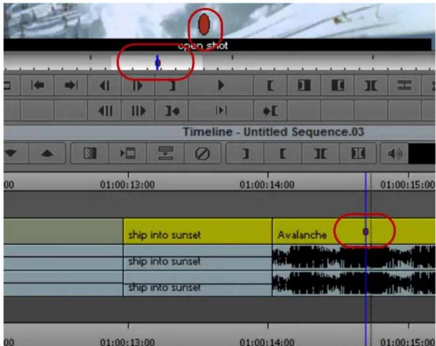
Example of a marker in the monitor, position bar and in the Timeline
You can add markers to your source material while you are in an editing session, as described in "Adding Markers While Editing" on page 525.
When you export sequences with markers as AAF files, the marker information is included. A Pro Tools editor can then choose to import the markers as Pro Tools as markers. The markers contain the same information as markers in your Avid editing system.
Adding Markers While Editing
To add markers and comments while in an editing session:
- Load a clip or sequence.
-
(Option) Select a specific track by using the Track Selector panel.
See "Understanding the Track Selector Panel" on page 707. -
Cue to the frame, and click an Add Marker button.
The Add Marker buttons are in the More tab of the Command palette.
The Marker edit entry window opens. The marker name, color, frame, and track information appear. By default, the marker name is the user name logged onto your system.

The following illustration shows the Marker edit entry window.

Marker edit entry window. Top: a comment in the comment area. Bottom: button to open the Markers window
- (Option) Type a new name in the Name text box.
- Type your comments in the comment area of the Marker edit entry window.
- Change the color from the Color menu or change the marker name.
- To save your information, click OK, or press the Enter (Windows) or Return (Macintosh) key.
The information is stored with the marked frame. The marker oval appears in the Timeline, in the position bar, and at the bottom of the frame in the monitor.
Adding Spanned Markers While Editing
You can add spanned markers while editing in the Timeline.
To add spanned markers and comments while in an editing session:
- Load a sequence in the Timeline.
- In the location where you want the spanned marker, add a Mark In and a Mark Out.
-
Select Tools > Command Palette and click the More tab.
-
Press Ctl + Alt (Windows) or Command + Shift (Macintosh) and click an Add Marker button.
The Marker edit entry window opens. The marker name, color, frame, and track information appear. By default, the marker name is the user name logged onto your system.

- (Option) Type a new name in the Name text box.
- Type your comments in the comment area of the Marker edit entry window.
- Change the color from the Color menu or change the marker name.
- To save your information, click OK, or press the Enter (Windows) or Return (Macintosh) key.
The spanned marker appears in the Timeline on the Timecode 1 track.

You cannot create overlapping spanned markers, nor can you move a spanned maker on top of another spanned marker.

When you open Tools > Markers, the Markers window will display the markers included in your sequence. The marker icon lets you easily identify a single frame marker (oval) and a spanned marker.

To delete a marker, click to select the marker in the Markers window and press the Delete key.
Adding Markers On-the-Fly while Playing
To add markers on-the-fly while playing:
- Load a sequence or clip.
See “Loading and Clearing Footage” on page 503. -
(Option) Select a specific track, using the Track Selector panel.
See "Understanding the Track Selector Panel" on page 707. -
Map the Add Marker button to a key by doing the following:
a. Open the Command Palette, click the More tab, and select Button-to-Button Reassignment.
b. In the Settings list of the Project window, double-click Keyboard.
c. Drag an Add Marker button to a key on the Keyboard palette.
a. Open the Command Palette, click the More tab, and select Button-to-Button Reassignment. b. In the Settings list of the Project window, double-click Keyboard. c. Drag an Add Marker button to a key on the Keyboard palette.
For more information about mapping buttons to keys, see “Mapping User-Selectable Buttons” on page 112.
- Click the Play button, and every time you want to add a marker, press the key to which you mapped the Add Marker button.
- (Option) Map different Add Marker buttons to different keys to be able to add more than one color of marker.
To add comments to the markers:
-
Stop playing.
-
Do one of the following:
▶ Double-click the marker in the position bar under the monitor.
▶Click the large oval on the frame in the monitor.
▶ Double-click the marker in the position bar under the monitor. ▶ Click the large oval on the frame in the monitor.
A Marker edit pane opens. The marker name, color, frame, and track information appear. By default, the marker name is the user name logged onto your system.

Marker edit entry window. Top: a comment in the comment area. Bottom: button to open the Markers window
- (Option) Type a new name in the Name text box.
- Type your comments in the comment area of the Marker edit pane.
- (Option) Change the color from the Color menu or change the marker name.
- To save your information, click OK, or press the Enter key.
The information is stored with the marked frame. The marker oval appears in the Timeline, in the position bar, and at the bottom of the frame in the monitor.
- (Option) Click the Marker icon in the to edit marker information.
To keep the Marker edit pane from opening:
- Select Tools > Markers.
The Markers window opens.
- Select Disable Markers Popup from the Fast menu.
The Marker edit pane now does not open even if you double-click a marker.
Finding Markers
To quickly go to a frame with a marker while editing:
▶ Search for a particular comment by selecting Edit > Find.
Editing Marker Information
You can open the Marker edit entry window directly from a monitor, from the position indicator bar, or from the Markers window. In the Marker edit entry window, you can change the color of a marker, the marker name, or the text of the comment associated with a marker.
To edit Marker information in the Marker edit entry window:
- Do one of the following:
- Click the oval Marker icon in the Source or Record monitor.
- Double-click the marker in the position indicator bar.
-
In the Markers window, right-click a marker item, and then select Edit Marker.
The Marker edit entry window opens. -
Do one or more of the following:
▶ Select from the Color menu to change the color of the Marker icon.
▶Type a new marker name.
▶Enter new text or update the current text comment.
- Click OK.
Copying Markers from Source Clips
You can copy all markers currently placed in source clips directly into the sequence as you edit. The markers and the marker text appear in all sequence segments that reference the source clips.
To automatically copy source markers as you edit:
- Double-click Composer in the Settings tab of the Project window.
The Composer Settings dialog box opens. - Click the Edit tab.
- Select Copy Source Markers.
- Click OK.
Marking an Area Using Markers
You can mark the area between two markers by using the Mark Marker button.
To mark the area between two markers:
- Move the position indicator between two markers.
- Click the Mark Markers button in the Edit tab of the Command palette.

The area between the two markers is selected.
Moving to the Previous or Next Marker
You can move to a frame marked by a marker by using the Go to Previous Marker button or the Go to Next Marker button.
To move to the previous marker:

Click the Go to Previous Marker button in the Move tab of the Command palette.
To move to the next marker:

Click the Go to Next Marker button in the Move tab of the Command palette.
Deleting Markers
You can delete markers using the Delete key, or the Markers window.
To delete a single marker:
- Select a marker in the Timeline or in the position bar.
- Press the Delete key.
The selected marker is removed.
To delete markers using the Markers window.
▶ See “Working in the Markers Window” on page 532.
Using the Markers Window
The Markers window lets you quickly add comments, go to marker marks, copy and paste markers, export and import markers, delete markers, and print a list of markers in the currently loaded clip or sequence. Many features of the Markers window are similar to those of the Bin window.
You can use the Markers window to:
- Go to the marker in the sequence or clip.
- Find frame, timecode, and footage information about each marker.
- Modify and sort the display.
- Display frames for easy visual reference.
- Change the color of the Marker icons.
-
Delete a single marker or multiple markers.
-
Export markers to send out as a review and approval file.
- Print the Markers window.
This is especially useful for identifying and listing specific frames to be used in an effect, for example. You can also make a list of IN and OUT points for adding music.
- Copy and paste markers from one clip or sequence to another.
The following illustration shows a Markers window with three markers.

Viewing Markers in the Markers Window
The Markers window is monitor specific. If you have selected the Source monitor, the Markers window displays the markers for the clip in the Source monitor. If you have selected the Record monitor, the Markers window displays the markers for the sequence in the Record monitor.
To view markers in the Markers window:
- Load the sequence containing the markers.
- Do one of the following:
Right-click the Source or Record monitor and select Markers.
▶Select Tools > Markers.
Working in the Markers Window
You can perform a number of basic procedures in the Markers window. You can select markers, go to the frame marked by a marker, display marker frames or additional information, sort markers, change marker column widths, change marker colors, and delete markers.
You can also:
- Export and import markers
For more information, see “Exporting and Importing Markers” on page 534.
• Copy and paste markers
For more information, see “Copying and Pasting Markers Using the Markers Window” on page 535. - Print the contents of the Markers window
For more information, see “Printing the Contents of the Markers Window” on page 536.
To select a marker item:
Click anywhere in the marker item's row except in the Comment column.
To browse through the list of marker items:
▶Press the Up Arrow and Down Arrow keys.
To go to the frame marked by a marker item:
▶Double-click the marker in the Markers window.
▶Right-click the marker, and select Jump to Marker.
To display the frame associated with a marker:
▶Right-click, and select Show Images.
To display a timecode column, a footage column, or a frame number column in the Markers window:
▶Right-click, and select Display > Frame Number, Timecode, or Footage.
To sort markers:
- Click the heading of the column that you want to sort.
- Right-click, and select Sort Column (to sort in ascending order) or Reverse Sort Column (to sort in descending order).
To change column widths:
- Click the heading of the column that you want to resize.
- Right-click, and select Enlarge Column or Reduce Column.
To change the color of a Marker icon:
▶ Right-click the marker icon, select Change Marker Color, and select a color.
To delete markers:
- Click a marker item, or Ctrl+click (Windows) or Command+click (Macintosh) multiple marker items.
- Press the Delete key.
Exporting and Importing Markers
You can export markers from a sequence or a clip. A text (.txt) or XML (.xml) file is created when you export the marker and a tab-delimited file or XML file displays all the information about the marker. You can then send the .txt or .xml file to those who need to review and give feedback about the sequence or clip. They can place additional comments in the text file or XML file and send it back for you to reimport the marker comments back into your sequence.

You can also import the text file into a spreadsheet program, such as Excel.
You can also use the Markers window to import markers back into your sequence.
To export markers:
- From the Markers window, right-click and select Export Markers and select Text or XML.
A dialog box opens, asking if you want to export only the selected markers or export all markers.
- Click All or Selected.
The Choose location for Exported Markers dialog box opens.
- Type a file name and click Save.
The marker is saved as a either text file (.txt) or XML (.xml) file.
To import markers.
- With a sequence loaded in the Record monitor, right-click and select Markers.
- From the Markers window, right-click and select Import Markers.
The Import dialog box opens.
- From Files of type, select the tab-delimited file or Text/XML file containing the markers you want to import, and then click Open.
- (Option) Another way to import a marker file is to select the tab-delimited marker file or the xml file and drag it into the Markers window.
Creating a Marker Text (.txt) File
You can create a Marker text file if you don't have access to an Avid system. This lets you make timecode-specific comments offline and give them to an editor to import into a sequence. The Marker text file is a tab-delimited file which must be created with certain parameters. This file can be edited in a text editor application or in a spreadsheet program. The Marker text file can be exported from or imported into the Markers window. See “Exporting and Importing Markers” on page 534.
The fields in the tab-delimited file are required and must be in the order shown in the following procedure. The following lines are examples:
John
Mary
To add comments or information into the Marker text file:
- Type each line of the file using the following syntax:
NameFrame Track Color Comment - Enter the color names as follows: red, green, blue, cyan, magenta, yellow, black, white
- Enter the track names as follows: V1, V2, V3, etc, A1, A2, TC1
Copying and Pasting Markers Using the Markers Window
You can use the Markers window to copy a single marker or multiple markers and then paste them into another clip or a sequence. The copied marker is placed in the same frame position when it is pasted into the new clip. If the frame position does not exist in the new clip, then the paste does not occur.
You can also use a text editor to cut and paste markers in the Markers window. This lets you move markers easily between clips, sequences, tracks, or different users on your system.
Timecode, clip data, color, marker identification, and comments are all associated with a marker entry. You can edit the entries before pasting them into a new clip or sequence using the Markers window, or you can save the marker information as a text file and distribute it as needed.
To copy markers from a clip and paste them into a new clip using the Markers window:
- Select the markers in the Markers window by doing one of the following:
▶Click a single marker.
▶Ctrl+click (Windows) or Command+click (Macintosh) multiple markers.
- Do one of the following:
▶Select Edit > Copy.
▶Press Ctrl+C (Windows) or Command+C (Macintosh).
-
Load a new clip in the Source monitor.
-
Click the Marker window and do one of the following:
▶Select Edit > Paste.
▶Press Ctrl+V (Windows) or Command+V (Macintosh).
The marker is pasted into the new clip.
To copy markers from a clip and paste them into a sequence using the Markers window:
- Select the markers in the Markers window by doing one of the following:
▶Click a single marker.
▶Ctrl+click (Windows) or Command+click (Macintosh) multiple markers.
- Do one of the following:
▶Select Edit > Copy.
▶Press Ctrl+C (Windows) or Command+C (Macintosh).
- Load a sequence into the Record monitor or into the Timeline.
- Click the Marker window and do one of the following:
▶Select Edit > Paste.
▶Press Ctrl+V (Windows) or Command+V (Macintosh).
The marker is pasted into the sequence.
To copy and paste markers using the Markers window and a text editor:
- Select the markers in the Markers window by doing one of the following:
▶Click a single marker.
▶Ctrl+click (Windows) or Command+click (Macintosh) multiple markers.
- Do one of the following:
▶Select Edit > Copy.
▶Press Ctrl+C (Windows) or Command+C (Macintosh).
- Open a text editor application, and paste the selection into the document.
The marker information displays in the text document.
Printing the Contents of the Markers Window
You can print the complete contents or the current view of the Markers window.

If you select Show Images to display the frame associated with each marker and you want to print the frames, you must use the procedure for printing the current view of the Markers window. Printing the complete contents does not print the frames.
To print the current view of the Markers window:
- Make sure your printer is correctly set up.
- Expand the view of the Markers window to display the information you want to print.
- Select File > Page Setup.
The Page Setup dialog box opens, reflecting the specific options for your printer.
-
Select the Page Setup options.
-
Click OK.
-
Select File > Print.
The Print dialog box opens, reflecting the specific options for your printer.
-
Select the Print options.
-
Click OK (Windows) or Print (Macintosh).
The system prints the current view of marker information.
To print the complete contents of the Markers window:
- Make sure your printer is correctly set up.
- Click the Markers window to make it active.
- Press Ctrl+Alt+P (Windows) or Command+Option+P (Macintosh) to place the marker information in the Console window.
- Select Tools > Console.
The Console window opens.
-
Select File > Page Setup.
The Page Setup dialog box opens, reflecting the specific options for your printer. -
Select the Page Setup options.
-
Click OK.
-
Select File > Print.
The Print dialog box opens, reflecting the specific options for your printer.
-
Select the Print options.
-
Click OK (Windows) or Print (Macintosh).
The system prints the marker information displayed the Console window.
Disabling the Marker Edit Window
If you want to add markers without including comments, you can modify the behavior of the Marker edit window so that it does not open each time you create a new marker. This lets you add markers quickly and then edit marker information later.

This option is selected by default if you upgraded your Avid editing application from a previous version where the “Disable Markers Popup” option was selected.
You can also disable the Marker edit window so it only opens from the Markers window. For information on accessing the Marker edit window, see “Editing Marker Information” on page 530.
To keep the Marker edit window from opening each time you add a marker:
- Select Tools > Markers.
The Markers window opens.
- Select Disable Marker Popup when Adding from the Fast menu.
The Marker edit window now does not open when you add markers.
To keep the Marker edit window from opening:
- Select Tools > Markers.
The Markers window opens.
- Select Disable Marker Popup Always from the Fast menu.
The Marker edit window now does not open even if you double-click a marker.
Finding Frames, Clips, and Bins
Once you have captured, viewed, marked, and subcataloged numerous clips for a project, you might have difficulty relocating specific clips or frames among several bins. Your Avid editing application provides a number of features for quickly locating and cueing footage, including conventional timecode and frame-offset techniques, text searches, and Match Frame and Find Bin commands.
Using Timecode to Find a Frame
You can cue a loaded clip or sequence to a specific frame by typing timecode values with the numeric keypad on the right side of the keyboard. In addition, you can cue backward or forward from the current location in the clip or sequence by a specified number of minutes and seconds, or feet plus frames, by using positive or negative frame-offset values.
The system interprets the numbers you type with the numeric keypad according to the type of tracking format you have selected from the Tracking Information menu (timecode or frames). If you have two rows of information displayed above the monitor, the system looks at the top row. For more information on selecting the display of tracking information, see “Displaying Tracking Information” on page 490.
To use timecode to find a frame, the top row of information must include timecode, for example, V1.
To cue to a frame based on a known timecode:
- Click the monitor that is displaying the clip or sequence you want to search.
- Select a timecode tracking format from the Tracking Information menu that appears above the monitor.
If two rows of information are displayed above the monitor, make sure the timecode format is in the top row.
- (Option) If you are using a notebook computer or a keyboard that does not have a dedicated numeric keypad, press and release the left Control key twice quickly.
This lets you enter timecode using standard keys on the keyboard, such as the number keys and the Enter key (Windows) or Return key (Macintosh).
- Enter the timecode for the frame by using the numeric keypad on the right side of the keyboard.
If you have performed step 3 on a notebook computer or a keyboard that does not have a dedicated numeric keypad, use the standard keyboard number keys.

Example of timecode entry with the numeric keypad. The timecode appears in the monitor. In this example, the interface displays master timecode.
Use one of the following formats:
Format Description
SMPTE timecode Use two digits each for the hours, minutes, seconds, and frames. For example, type 01230200 to enter 01:23:02:00.
Current timecode To find a timecode that starts at the same hour, minute, or second as the current timecode, type only the last digits. For example, if the current timecode is 1:05:12:13 and you type 425, the system finds the frame at 1:05:04:25.
- Press Enter on the numeric keypad.
If you have performed step 3 on a notebook computer or a keyboard that does not have a dedicated numeric keypad, press the Enter key (Windows) or Return key (Macintosh).
To cue a frame using frame offset timecode:
- Click the monitor that is displaying the clip or sequence that you want to search.
- (Option) If you are using a notebook computer or a keyboard that does not have a dedicated numeric keypad, press and release the left Control key twice quickly.
This lets you enter timecode using standard keys on the keyboard, such as the number keys and the Enter key (Windows) or Return key (Macintosh).
- Using the numeric keypad, type a plus sign (+) to move forward or a minus sign (−) to move backward from the current position.
If you have performed step 2 on a notebook computer or a keyboard that does not have a dedicated numeric keypad, use the standard keyboard plus (+) and minus (-) keys.
- Type a number for the frame offset, and then press Enter on the numeric keypad.
If you have performed step 2 on a notebook computer or a keyboard that does not have a dedicated numeric keypad, use the standard keyboard number keys, and then press the Enter key (Windows) or Return key (Macintosh).
Use the following formats:
Format Description
One or two digits Type 1 through 99 to specify a number of frames forward or backward. For example, type-42 to move backward 42 frames.
Format Description
| Three digits Type | 100 or greater to move forward or backward a specified number of seconds and frames. The results vary depending on the tracking format you have selected in the Tracking Information menu that displays information above the monitor. For example, if you type+100 and the master timecode is displayed in the top row of the tracking information above the monitor, you move forward 1 second and zero frames. If you select frames to display above the monitor and type +100, you move forward 100 frames. |
| Frames only To move by frames (regardless of the display in the Tracking Information menu) add an f to the end of the number you type. For example, if you have a timecode displayed in the Tracking Information menu and type +100f, the display changes to 3:10 (3 seconds and 10 frames) and you move forward 100 frames. | |
Searching for a Clip or Sequence with Text Find
Text find allows you to enter text and search bins, Scripts and the Timeline for the information you enter. You can customize your search by selecting to only search the active bin or search all bins across a single project. Bins do not have to be open for the system to search in them, Find searches all bins and scripts within your project. The text find feature is included with your Avid editing application.
PhraseFind (the phonetic find feature) is purchased as a separate option. Both text find and PhraseFind can be used together or independently of each other.
For information about the phonetic search option, see “PhraseFind” on page 555. If you have not purchased PhraseFind and would like more information, click the PhraseFind button in the Find window, then click Buy. You will be redirected to the Avid website to get more information about PhraseFind. If the dialog box in the editor asks you to quit your Avid editing application, click Cancel.
For a table of all the options available in the Find Window, see “Find Window Attributes” on page 572.
Things You Should Know About Text Find
- You can continue to work, while the system indexes your project.
- The system creates a SearchData folder located in your Projects folder when you index text or phonetic searches. If you are working in an ISIS environment, the SearchData folder is located inside the Project client (computer name) folder. You can change the default location of the Search Data folder. See “Setting the Location of the SearchData folder” on page 545.
• All tabs: Clips and Sequences, Script Text, and Timeline and Monitors tab apply to text find.
- The system does not search and find referenced clips in a sequence.
- If you make a change to a bin (or add a new clip to the bin), you must save the bin first in order for the system to find the changes.
- The system searches through all available columns in your bins including metadata columns, even if they are not visible in your current bin.
- The use of quotes in search queries has no affect on your results.
- The following characters: @#\$%^&*()=+[]\ are recognized by text find.
- When you perform an Edit While Capture in an Interplay environment, you need to update the bin so that the system indexes your new media. After you capture, right-click the clip in the bin and select Update from Interplay. Then save the bin. When you perform a text find, the system should find the new captured clips.
- To make sure all your open bins are indexed, click the Project window and select File > Save All. This will save all opened bins. When the Bin Index light turns solid green, perform your search. This will ensure that your results include the most up-to-date files.
- Before you filter to refine your results, you need to first perform a find, then the Filter columns are selectable.
To open a search window:
- Press Ctrl+F (Windows) or Cmd+F (Macintosh), or select Edit > Find.
The Find window opens.


The Bin Index status at the bottom of the window indicates if the data files in your bins have been indexed. A full green display indicates that your files have been indexed and are ready to search. A partial green display indicates that the index is in process and if you perform a search, your results might not be complete.
If you want to stop the indexing process, click the Settings button in the Find window and click Stop Indexing. The indexing stops and the button changes to Start Indexing. The indexing remains off until you click Start Indexing.
- Type a word or phrase that you are looking for in the text box.
- Select to search in Clips and Sequences, Script Text, or Timeline and Monitors.
- If you select Clips and Sequences, then select from the menu:
Bins in Project
Bins and Scripts in Project
The system searches for the text criteria in all the bins/scripts within the project regardless if the bin/script is currently opened.
| Current Bin The system searches for the text criteria in the lastactive bin. The system then selects the first occurrencein the bin. Press Ctrl+G (Windows) or Cmd+G(Macintosh) to take you to the next occurrence |
- If you select Script Text, then select from the following:
| Scripts in Project The system searches for the text criteria in all the scripts within the project regardless if the script is currently opened. |
| Current Script The system searches for the text criteria in the last active script. The script must be open and active in order for the system to search within the script. |
- A script text search displays all matches in the script, to find the next occurrence of your text criteria, press Ctrl+G (Windows) or Cmd+G (Macintosh) in your script.
- If you select Current Script, you can select "Whole words only" to search for only that word.
- Select Ignore Case if you want the system to search for the text regardless if it is upper or lower case characters.
- If you select Timeline and Monitors, then select from the following:
| Markers The system searches for clips in the Timeline that contain the marker text. The blue position bar jumps to the marker position on the clip and displays the marker information in the Source/Record monitor. |
| Clip Names The system searches for clips in the Timeline that contains the clip name. The blue position bar jumps to the head frame of the clip. |
| Timeline Text The system searches for clips in the Timeline that contain |
| Timeline text based on what is displayed in the Clip Text pulldown menu. The blue position bar jumps to the head frame of the clip. |
- If you would like to open the clip(s) in a Source monitor when you double-click a clip in the Results window, then select Load into monitor.

Loading the clip in the Source monitor is dependant on the option you have chosen for "Double-click loads object in" in your Bin Settings.
- With your text criteria entered, click Find or press Enter.
A Cancel button appears and the system informs you that it is finding your text criteria.
The results appear in the Results window. If you select Current Bin, the clips are selected in the bin and do not display in the Results window. The system displays the total number of items found after your search.

To select the next occurrence in your bin, press Ctrl+G (Windows) or Cmd+G (Macintosh).
- (Option) To refine the number of results, you can enter additional criteria in the filters. Select a specific column from the Filter menu that you would like to search in, then enter additional text relating to that column. The column you are searching on does not have to display in the bin.

Click the “+” button to add additional filters. Click the “-” button to remove filters. If the last filter appears, the “-” button removes the text, not the filter.
The filter menu populates after the initial search.
For information about filtering your results, see “The Results Window” on page 569 and “Filtering Your Find Results” on page 572.
Setting the Location of the SearchData folder
When creating a new project you can choose the location of the SearchData folder.
To choose the location of the SearchData folder:
- Start the editing application.
- In the project window, select New Project.
The New Project dialog opens.
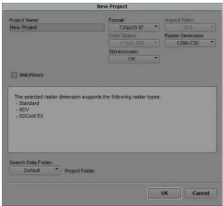
- Select the Search Data Folder menu. Select either Default, Local Default, or Other. To change the location from the Default options, select Other.
- Choose the folder where you want the SearchData folder to reside.
- Click OK.
A subfolder with the project name is created in the folder you selected in step 4.

You can also set the SearchData folder in the Settings tab of the Find Window.
Using Match Frame
The Match Frame feature lets you locate the source clip for the frame currently displayed in either the Record monitor or the Source monitor. This feature is useful when you want to relocate and reedit source material, such as subclips and master clips.
Match framing loads the source clip into the Source monitor, cues to the matching frame in the source clip, and marks an IN point. Any original IN and OUT points are removed from the source clip.
You can also use the Match Frame feature to locate clips quickly, based on media relatives, when you have forgotten their location. For example, you can matchframe a cut in the sequence to its original subclip, matchframe the subclip to the original master clip, and then locate the bin in which the master clip is saved. Match framing stops when you reach the master clip.
You can also use the Match Frame feature to locate the source clip for a traditional motion effect.

You can also locate frames in a sequence that match a selected source frame; see “Performing a Reverse Match Frame” on page 547.
Match framing does not create a permanent sync relationship between clips but provides a convenient way of locating, marking, and editing matching material.
The Match Frame button appears by default in the second row of buttons below the Source monitor. To match frame from footage in the Record monitor, you must map the button from the Other tab of the Command palette to the Record monitor palette or the Keyboard palette. For information about mapping buttons, see “Mapping User-Selectable Buttons” on page 112.
To use Match Frame to locate the source clip for a selected frame or motion effect:
- Load a sequence into the Record monitor or a subclip into the Source monitor.
- Move the position indicator to the frame or motion effect that you want to match.
- In the Track Selector panel, select the track for the frame that you want to match.
For more information, see “Understanding the Track Selector Panel” on page 707 and “Selecting Tracks for Matching Frames” on page 548.
- Do one of the following:

▶Click the Match Frame button.
The source clip is loaded into the Source monitor, and any previous IN or OUT points are removed. A new IN point is marked at the matching frame.
Alt+click (Windows) or Option+click (Macintosh) the Match Frame button.
The source clip is loaded into the Source monitor, and any previous IN or OUT points are maintained.
▶Press and hold Alt+Ctrl (Windows) or Option+Command (Macintosh), and click the Match Frame button.
The source clip of the motion effect is loaded into the Source monitor.
Performing a Reverse Match Frame
The Reverse Match Frame feature lets you locate frames in a sequence that match a selected source frame.
To perform a reverse match frame:
- Load the source footage into the Source monitor.
- Move the position indicator to the frame that you want to match.
- Select the appropriate tracks in the Timeline.
For more information, see “Understanding the Track Selector Panel” on page 707 and “Selecting Tracks for Matching Frames” on page 548.
The system searches all selected tracks in the Record monitor for the frame on all selected tracks in the Source monitor.

- Click the Reverse Match Frame button in the Other tab of the Command palette.
Your Avid editing application cues the sequence to the matching frame on the record side. If the frame exists in more than one place, the sequence cues to the first location of the match frame and continues through the sequence to subsequent locations each time you click the Reverse Match Frame button.
Selecting Tracks for Matching Frames
Track selection determines the match frame. If you select a video track, your Avid editing application m matches a frame from the video. If you enable several tracks, your Avid editing application matches the frame from the highest selected track level, in descending order: V1, A1, A2, and so on.
You can match frame a single track without having to turn off all other tracks. With audio, you can select the audio track that you want to match frame instead of having your Avid editing application match frame the top audio track.
To matchframe a selected frame on a single track:
▶ Right-click the track number that you want to match frame, and select Match Frame Track.
Finding a Bin
With a clip or sequence loaded into a monitor, you can quickly find the original bin in which it is stored by using the Find Bin button. Clicking this button finds the bin, opens it, and highlights the clip or sequence within the bin. This works for sequences, subclips or clips within sequences, or clips in the Source monitor.
To find the bin in which a specific clip is located:
- Load a clip into the Source monitor.
- Click the Source monitor to activate it.
- Click the Find Bin button in the Other tab of the Command palette.
Your Avid editing application highlights the clip in the bin.
To find the bin in which a specific sequence is located:
- Load a sequence into the Record monitor.
- Click the Record monitor to activate it.

- Click the Find Bin button.
Your Avid editing application highlights the sequence in the bin.
To find the bin in which a specific clip in a sequence is located:
- Move the position indicator to the clip within the sequence.
- Press and hold the Alt key (Windows) or the Option key (Macintosh), and click the Find Bin button.
Your Avid editing application opens the bin and highlights the clip.
Locating a Master Clip from a Subclip in a Sequence
You can use the Match Frame and Find Bin buttons together to find the original clip in the bin for a subclip that was edited into a sequence.

For this operation, you must have the monitors in the two-monitor display and the Match Frame button must be mapped below both the Source and Record monitors.
To locate a master clip from a subclip:
- Cue to the subclip in the sequence.
- Click the Match Frame button in the Record monitor to load the subclip into the Source monitor.
- Click the Match Frame button in the Source monitor to load the original master clip into the Source monitor.
- Click the Find Bin button in the Source monitor to open the bin and highlight the master clip.


Finding a Frame
The Find Frame button, located in the Other tab of the Command palette, lets you trace a captured frame of footage displayed in a sequence or source clip back to its analog source on tape. This is useful for finding frames for color correction or for recapturing specific clips to lengthen them or alter capture parameters.
To find a frame:
- Make sure the source deck is properly connected to the system, and load the clip or sequence.
- In the Timeline or position bar, move the position indicator to the frame you want to find.
- Click the Find Frame button in the Other tab of the Command palette.

If the tape is not in the deck (for example, you do not know which tape the footage is on), a dialog box prompts you to insert the appropriate tape.
4. Insert the tape.
Your Avid editing application cues to the requested frame and displays the frame. You can recapture as necessary.
Sequence and Clip Information Summary
You can generate a report to display information about the contents of a sequence. For example, you can generate a list of the types of effects in your sequence or the location of a particular effect. You can also create a clip summary or a source summary. This allows you to display a list of clip names, tape names, offline clips, and path locations of imported clips contained in your selection.
You generate reports from the Sequence Report dialog box, which you can access from the Source monitor, the Record monitor, or directly from a sequence in a bin. The Sequence Report dialog box allows you to select your criteria and create a report that displays in a text editor. You can then search the summary for the exact information you want.
Example 1: Preparing for Online Editing
When you move your sequence from an offline system to an online system, you can run an effect summary and a source summary report. The Effect Summary displays a list of all effects, including a separate list of plug-ins used. The Source Summary lists all the tapes you need for recapture and all of the import paths for imported graphics.
Example 2: Finding Specific Effects
You use the Effect Summary and Effect Location List to find a particular effect. When you output the summary to a text editor, you can search the report to find all occurrences of the particular effect. In addition, you can type the start or end timecode value for each occurrence into the Source/Record monitor to go to the start of the effect in the Timeline. You might find this useful when you need to replace or modify a specific plug-in, for example.
Example 3: Plug-in Information
An Effect Summary displays a list of effects found in the selection, including how many times the sequence uses an effect. For plug-ins loaded on your system, a section displays a summary of the plug-ins used, displaying the name, the vendor, the version and the ID of the plug-in. This can help by providing a list of the plug-ins needed for online work.

If a plug-in is not loaded on your system when you generate the summary, if you select the option "Show Missing Effects Only" from the Sequence Report dialog box, the information displays "unavailable effect," in addition to the plug-in name, the plug-in ID (is this gone?), and other information associated with the effect. (Is the vendor and version number displayed). This is helpful when identifying the effect.
Creating a Summary of Effects and Source Information
Before you use the Sequence Report dialog box to create a summary of effects, source information, or clip information, you might want to do the following:
- Determine if you want the report to cover specific tracks or a section of the sequence between In and Out points. Loading a sequence in the Source/Record monitor before you generate a report allows you to select which part of the sequence about which you want information.
- Choose the summary options you want information on — types of effects, location of effects, source information, or clip information.

You can modify the sequence name and the starting timecode in the Sequence Report dialog box.
To generate a summary report:
- Do one of the following:
From a bin, right-click a sequence and select Sequence Report. You can select multiple sequences for generating reports.
With a sequence loaded in a monitor, right-click the monitor and select Sequence Report.
The Sequence Report dialog box opens.

- (Option) Do the following:
▶If you selected specific tracks, click Enabled Tracks Only.
▶If you set In and Out points, click Use Marks.
If you want to run a report on the entire sequence regardless of tracks or marks, do not select either of these options.
- Select the Summary Info options you want to include in your report. For information on report options, see “Summary Information Options” on page 553.
- Click Generate Report.
The Save Summary Output File As dialog box opens.
- Use the default file name or rename the report and choose a folder to save the report to, click Save.
If you select more than 8 sequences, a dialog box asks if you want to generate sequence reports for all selected items.
The application writes the report to a text file and opens a text editor.
Summary Information Options
The following options allow you to select which information to include in the sequence report.
Summary Option Suboption Description
| Create Effect Summary | This displays the types of effects and how many were found in your sequence, the breakdown by effect type, and an effect plug-in summary. If you have selected individual tracks or selected IN and OUT points, only those effects that fall within those parameters appear. | |
| Create Effect Location List | This displays the location of an effect. Depending on the criteria you selected, this displays track, start timecode, end timecode and effect name. | |
| Skip Non-Renderable Effects | Select this option if you do not want any non-renderable effects, such as pan/volume effects, to appear in the report. | |
| Skip Relationship-Only Color Correction | Select this option if you do not want any color correction effects with only relationships to appear in the report. | |
| Show Nested Effects Only | Select this option if you want to only display the nested effects in your sequence. Effects that are nested inside of other effects show the parent effect track they are applied to with the track name in parentheses and indented to show the nesting relationship. | |
| Show Missing Effects Only | Select this option if you want to only display the plug-in effects missing from your sequence. Plug-in effects that are missing in your sequence display as “Unavailable Effect,” but also lists the type of effect and other important information which help you identify the type of effect. This option is helpful when you move your sequence to a system that does not have the plug-in installed. |
Summary Option Suboption Description
| Create Clip Summary orCreate Source Summary | Depending on the criteria you selected, a Clip Summary displays the number of clips found, type of clip, track, offline information, clip name, and clip Mob ID.A Source Summary displays the number of tape-based sources found, project name, tape name, tape ID, and tape Mob ID. It also displays a list of import paths for any imported clips, such as graphics. |
| Offline Only Select this option if you want to display offline clips and/or sources only. | |
| Skip Non-Selected Clips in Group Clips Select this option if you do not want any non-selected clips inside of a group clip to appear in the report. | |
| Show Globally Unique Identifier (UID) Select this option if you want to display the unique identifiers (Mob IDs) associated with the clips and sources in your sequence. |
13 PhraseFind
The PhraseFind option (phonetic find) searches and finds audio dialogue throughout bins in a single project. PhraseFind starts by indexing all the audio in your bins (based on the language you choose). You then enter search criteria, and the system searches through those bins for all occurrences of the audio search criteria you enter. PhraseFind indexes and finds audio in master clips, subclips and group clips. Only your project needs to be opened, you do need to have the bins open for the system to search them. The database returns the results of your find in the Results window. You can then continue to filter those results to find exactly what you are looking for.
The Find window in the Avid editing application, includes both the text find feature and the PhraseFind feature.
The PhraseFind feature is purchased separately. You must purchase and then activate your PhraseFind license to use this feature. For more information, see “Purchasing and Activating PhraseFind” on page 555.
For a table of all the options available in the Find Window, see “Find Window Attributes” on page 572.
Purchasing and Activating PhraseFind
The PhraseFind (phonetic search) option is sold separately from your Avid editing application. Once you purchase PhraseFind, you will receive a PhraseFind Activation ID that you use to activate the PhraseFind feature. You activate the PhraseFind feature with the Avid License Control tool. To find out the benefits of the PhraseFind feature, you can try out PhraseFind for a free 30-day trial period before you purchase.
You can also purchase and activate multiple seats of PhraseFind. For information about installing and activating volume licenses see the FlexNet Device Manager for Avid Guide on the Avid Knowledge Base.
How Do I Purchase PhraseFind?
- You can purchase PhraseFind through your Avid Reseller.
- You can purchase PhraseFind from your Avid editing application's Find window.
- You can purchase PhraseFind directly through the Avid web store at http://shop.avid.com, then search for PhraseFind.
How Do I Activate PhraseFind?
Once you purchase the PhraseFind feature and have received a PhraseFind Activation ID, you activate this option through the Avid License Control tool in the following ways:
- You can use an Internet connection to activate PhraseFind. Avid's License Control tool lets you activate online using your system identification (System ID) number and the Activation ID that came with the purchase of PhraseFind.
- If the system running your Avid editing application and PhraseFind is not connected to the Internet, you can activate PhraseFind by using a different computer with an Internet connection.
- If you do not have access to the Internet, you can activate PhraseFind over the telephone by calling Avid customer service.
- You can activate multiple PhraseFind licenses using the FlextNet Device Manager for Avid. For more information, see the FlexNet Device Manager for Avid Guide on the Knowledge Base.
What Will I Need to Activate PhraseFind?
- The PhraseFind Activation ID (obtained after you purchase PhraseFind)
If you purchased through an Avid Reseller, the PhraseFind Activation ID is on a sticker adhered to your Instruction letter. If you purchased through the Avid web store, you receive your PhraseFind Activation ID through an Avid e-mail or you can also view your Activation ID by logging in to your Store account at http://account.avid.com/.
- Your System ID
This number pre-displays if you have activated your Avid editing application. If the System ID does not appear, you can get the number in the following ways:
- The License Profile tab of the Avid License Control tool
- If you purchased your Avid editing application online, you received your System ID from Avid by e-mail
- The Avid editing application splash screen (Help > About Avid editing application)
- The Console of the Avid editing application (Tools > Console, then scroll to System ID)
- If you purchased your Avid editing application from the Avid store, you can also view your System ID number by logging in to your Store account at http://account.avid.com/
If you have a dongle attached to your Avid editing application, check the License Profile tab of the Avid License Control tool or use DongleManager to obtain your System ID. See the steps below for information about this utility.
- Your Device ID (you only need this if you are running PhraseFind on a system without an Internet connection). Check the License Profile tab of the Avid License Control tool.
To retrieve your System ID with a dongle attached:
- Navigate to one of the following locations:
▶(Windows) Program Files\Avid\Utilities\DongleManager
(Macintosh) Applications/Utilities/Avid Utilities/DongleManager
- Double-click DongleManager.
A window opens and displays your System ID.
- Copy the System ID, and then close the terminal window.
Running the 30-Day Trial of PhraseFind
Before you purchase PhraseFind, you can try it out for a 30-day period. After the 30 days, if you do not purchase PhraseFind, you will no longer have access to the PhraseFind feature. The system keeps you informed of how many days you have left before the trial period ends.

If you are running the Avid editing application trial version, you do not need to run the trial version of PhraseFind. The PhraseFind feature is included with the trial version of the Avid editing application.
To run PhraseFind for a 30-day trial period:
- Open your Avid editing application and an Avid project.
- Press Ctrl+F or select Edit > Find.
The Find window opens.
- Type a word or phrase in the text box, then click the PhraseFind button.
The system checks to see if you have PhraseFind on your system and then a dialog box opens.
- Click Run Trial.
The Avid editing application closes to start the phonetic indexer.
- Restart your Avid editing system.
Your trial is activated. Your 30-day trial of PhraseFind also includes access to all available languages during the trial. You do not need to activate any additional language packs at this time. However, you need to select your language from the Select a Language menu in the PhraseFind window.
- In the PhraseFind window, select your language from the Select a Language menu and wait for the PhraseFind Index to turn green.
To purchase PhraseFind during your 30-day trial period:
- Open your Avid editing application and an Avid project.
- Press Ctrl+F or select Edit > Find.
The Find window opens.
- Type a word or phrase in the text box, then click the PhraseFind button.
A dialog box opens which informs you of how many days you have left on your 30-day trial. This message displays with the remaining time only when you restart the Avid editing application and click PhraseFind again.
- Click Buy.

If the Buy button does not appear, close the Find window and restart your Avid editing application. Repeat the steps above.
The system opens the Avid web store, allowing you to purchase PhraseFind. Once you purchase PhraseFind and obtain your PhraseFind Activation ID, you can activate PhraseFind.
A dialog box opens informing you that Activation will quit your Avid editing application and launch the Avid License Control tool.
- Click Continue.
The Avid License Control tool opens.
To activate PhraseFind, see “Activating PhraseFind with the Avid License Control Tool” on page 560 to continue.
If You Purchased PhraseFind Through the Find Window
If you are working in your Avid editing application, you can open the Find window and click PhraseFind to purchase the PhraseFind feature. You will need an internet connection and you will be directed to the Avid store. Once you make your purchase, you will receive your PhraseFind Activation ID and be directed to the The Avid License Control tool to activate the PhraseFind feature.
To purchase PhraseFind through the Avid editing application's Find Window:
- Open your Avid editing application and an Avid project.
- Press Ctrl+F or select Edit > Find.
The Find window opens. - Type a word or phrase in the text box, then click the PhraseFind button.
A dialog box opens which informs you that PhraseFind is not activated on this machine. - Click Buy.

If you have not purchased PhraseFind and if the Buy button does not appear, close the Find window and restart your Avid editing application. Repeat the steps above.
The system opens the Avid web store, allowing you to purchase PhraseFind. Once you purchase PhraseFind and obtain your PhraseFind Activation ID, you can activate PhraseFind.
A dialog box opens informing you that Activation will quit your Avid editing application and launch the Avid License Control tool.
- Click Continue.
The Avid License Control tool opens, which allows you to activate PhraseFind.
To activate PhraseFind, see “Activating PhraseFind with the Avid License Control Tool” on page 560 to continue.
If You Purchased PhraseFind through an Avid Reseller or Directly Online
Once you purchase PhraseFind, you will receive your PhraseFind Activation ID. You need to open the Avid License Control tool to activate the PhraseFind feature.
The Avid License Control tool is installed with your Avid editing application and located in the Utilities folder.
To open the Avid License Control tool:
- Go to the following location:
(Windows) Start/All Programs/Avid/Utilities/License Control
(Macintosh) Applications/Utilities/Avid Utilities/License Control
The Avid License Control tool opens, which allows you to activate PhraseFind.
To activate PhraseFind, see “Activating PhraseFind with the Avid License Control Tool” on page 560 to continue.
Activating PhraseFind with the Avid License Control Tool
When you purchase PhraseFind and open the Avid License Control tool, you are ready to activate the PhraseFind feature. You can only use and activate PhraseFind on a single machine at one time.
If you have an Internet connection on the machine that you will be using PhraseFind, follow the instructions “To activate PhraseFind with the Avid License Control tool and with an Internet connection:” on page 561. If you do not have an internet connection, follow the instructions “To activate PhraseFind with the Avid License Control tool and with no Internet connection:” on page 563.
For more information on how to open the Avid License Control tool see, “If You Purchased PhraseFind Through the Find Window” on page 558 or “If You Purchased PhraseFind through an Avid Reseller or Directly Online” on page 559.
To open the Avid License Control tool:
- Go to the following location:
(Windows) Start/All Programs/Avid/Utilities/License Control
(Macintosh) Applications/Utilities/Avid Utilities/License Control
The Avid License Control tool opens, this allows you to activate or deactivate PhraseFind.
The Status column displays if PhraseFind is Activated, Not Activated, Deactivated or Trial.
The Action button displays as Activate or Deactivate.
To copy system information from the License Profile tab:
- With the Avid License Control tool open, click the License Profile tab.
The License Profile tab displays information about your system, including: Device ID, OS, System ID, Activation ID, software Version, if your software is activated or deactivated.
- Click Copy.
The information copies to your Clipboard.
You can cut and paste from the clipboard to an e-mail or create a text file, if you need to send system information to Avid Customer Support.
To activate PhraseFind with the Avid License Control tool and with an Internet connection:
- With the Avid License Control tool open, click Activate next to PhraseFind.
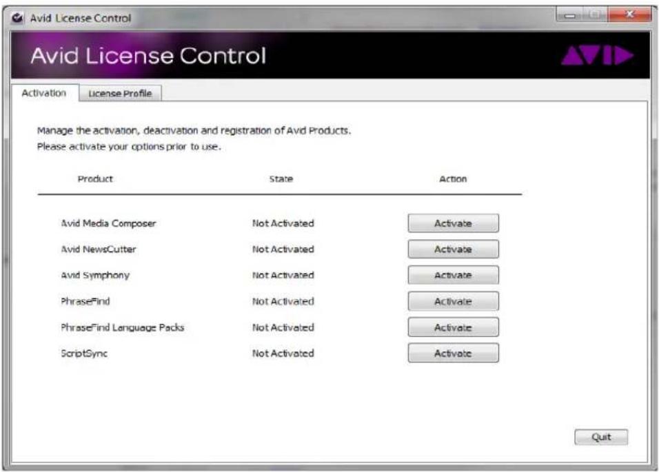
A dialog box opens.
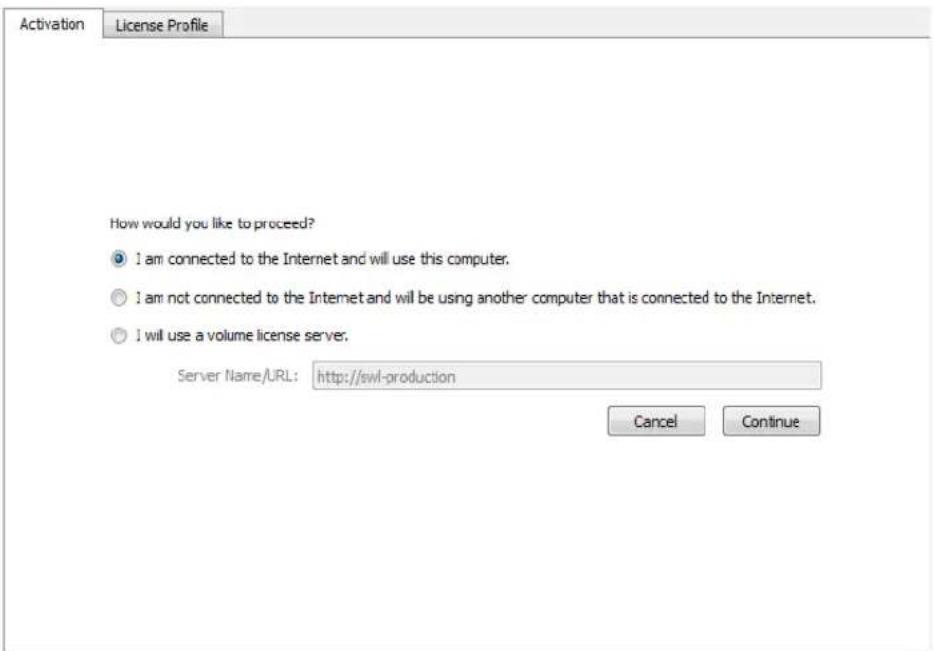
- If your computer has an Internet connection, select "I am connected to the Internet and will use this computer."
- Click Continue.
The Avid Activation dialog box opens.

- Enter your system identification number in the System ID text box.
This number pre-displays if you have activated your Avid editing application. If the System ID does not appear, see "What Will I Need to Activate PhraseFind?" on page 556 for more information.

If you have a dongle attached to your system, the system should pre-display your System ID.
You can copy and paste your system identification number and your Activation ID from a text file to the appropriate text boxes.
- Enter your PhraseFind Activation ID in the Activation ID text box.
Your Activation ID is located on the PhraseFind Instruction letter if you purchased through an Avid Reseller. If you purchased PhraseFind online, you received your Activation ID from Avid by e-mail. For more information, see “What Will I Need to Activate PhraseFind?” on page 556.
- Click Activate.
The Activation tool confirms your system information, and the Select the default language dialog box opens.
- Select your language.
The language you choose is the one free language included with PhraseFind. You can also purchase additional language packs and select different languages to search on in the Find window. For information about the PhraseFind Regional language packs, see “Activating Additional Regional Language Packs” on page 564 and “Selecting a Language” on page 567.
-
Click Select.
-
Click Quit.
PhraseFind successfully activates.
To activate PhraseFind with the Avid License Control tool and with no Internet connection:
- With the Avid License Control tool opened, click Activate next to PhraseFind.
A dialog box opens.
-
Select “I am not connected to the Internet and will be using another computer that is connected to the Internet.”
-
Click Continue.
The Avid Activation dialog box opens.
- On the second computer open a Web browser and navigate to http://avid.com/license.
The Avid Software License Activation page opens.
- In the Software License Activation Web page, enter your Activation ID and if you would like to have your Activation file sent to you, enter your e-mail address.
To find your Activation ID, see “What Will I Need to Activate PhraseFind?” on page 556.
Once the system verifies your Activation ID, the Device ID and System ID entries display.
- Enter your Device ID and System ID.
To find your Device ID or System ID, see “What Will I Need to Activate PhraseFind?” on page 556.
- Click Activate.
The system creates a license.bin file. This file contains license information needed to activate PhraseFind.
If you entered an e-mail address, the .bin file will be sent to you as an attachment. You can also download the .bin file directly from the site.
- Click Download to download the license.bin file to your system.
Depending on your web browser, the license.bin file could be located on your desktop or in a download folder.
- Move the license.bin file to the system you need to activate PhraseFind.
You can use a removable storage device such as a USB drive or you can transfer the data over your network.
- Open the Avid License Control tool.
- Click Browse and navigate to the license.bin file you moved to your system, then click Open.
- The Select the default language dialog box opens, click a language then click Select.
The Avid License Control tool confirms your system information. When the activation is complete, a message informs you that PhraseFind has been successfully activated and the button changes to Deactivate.
Activating Additional Regional Language Packs
If you purchased additional language packs, you need to activate and license all languages through the Avid License Control tool.
Each language pack you purchase for PhraseFind has a specific Activation ID associated with it. You cannot activate one language and then use the same Activation ID to activate another language. If you want to enable two different languages, you need to purchase two different Activation IDs.
Activating Additional Language Packs
- Go to the following location:
(Windows) Start/All Programs/Avid/Utilities/License Control
(Macintosh) Applications/Utilities/Avid Utilities/License Control
The Avid License Control tool opens.
- Next to PhraseFind Language Packs, click Activate.
A dialog box displays additional language packs.
- Select your language and click Activate.
You can only select one language at a time to activate. Each language pack has a unique Activation ID.
-
If your computer has an Internet connection, select “I am connected to the Internet and will use this computer.”
-
Click Continue.
The Avid Activation dialog box opens.
- Enter your system identification number in the System ID text box.
This number pre-displays if you have activated your Avid editing application. If the System ID does not appear, see “What Will I Need to Activate PhraseFind?” on page 556 for more information.

You can copy and paste your system identification number and your Activation ID from a text file to the appropriate text boxes.
- Enter your language pack Activation ID in the Activation ID text box.
If you purchased the PhraseFind Regional language packs online, you received your Activation ID from Avid by e-mail. You can also view your Activation ID by logging in to your Store account at http://account.avid.com/.
- Click Activate.
The systems activates the additional language packs.
Deactivating the PhraseFind License

If you need to move PhraseFind to a different computer, deactivate the PhraseFind license.

You must have an Internet Connection to deactivate PhraseFind.

You do not need to deactivate the Trial version of PhraseFind.
The steps below deactivates both PhraseFind and the PhraseFind Language Packs.
Deactivating PhraseFind
- Go to the following location:
(Windows) Start/All Programs/Avid/Utilities/License Control
(Macintosh) Applications/Utilities/Avid Utilities/License Control
The Avid License Control tool opens.
- Next to PhraseFind, click Deactivate.
A message appears informing you that the language packs associated with PhraseFind will also be deactivated.
- Click Yes.
PhraseFind deactivates and the button changes to Activate.
Follow the instructions on how to activate PhraseFind if you want to activate it on another computer.
Understanding PhraseFind
Now that you have purchased and activated PhraseFind, there are a few things that might help you understand how PhraseFind works.
Things You Should Know About PhraseFind
- For best results with PhraseFind, Avid recommends using Avid certified storage solutions.
- You can continue to work while the system indexes your project.
- The system creates a SearchData and a PhoneticData folder located in your Projects folder when you index text or phonetic searches. If you are working in an ISIS environment, the SearchData folder is located inside the Project client (computer name) folder. Within the PhoneticData folder is a “1” folder that holds the first 5000 files, a second (2) folder is created which holds the next 5000 files. If you delete these folders, the system creates a new SearchData folder and indexes your bins the next time you open a project.
- The system does not index clips that are offline. PhraseFind does index AMA clips as long as they are online.
- Only the Clips and Sequences tab applies to PhraseFind. The Script Text tab and Timeline and Monitors tab do not apply. (These tabs are used with text find.)
- You can purchase and have multiple language packs installed on your system, however, you can only choose one language at a time. A project can use multiple languages, but only one at a time.
• The use of quotes in search queries has no affect on results in PhraseFind. - The system does not search and find referenced clips in a sequence.
- PhraseFind searches words or phrases that are misspelled. You can enter search criteria that is spelled like it sounds.
- If you make a change to a bin (or add a new clip to the bin), you must save the bin first in order for the system to index and then find the changes.
- When you perform an Edit While Capture in an Interplay environment, you need to update the bin so that the system indexes your new media. After you capture, right-click the clip in the bin and select Update from Interplay. Then save the bin. When you perform a PhraseFind, the system should find the new captured clips.
- If you want to refresh your results, save a bin.
- Before you filter to refine your results, you need to first perform a find, then the Filter columns are selectable.
Selecting a Language
Avid supports several different languages. Language packs are purchased separately. You receive one free language with the purchase and activation of PhraseFind. You can purchase and have multiple languages licensed on your system, however, you can only use one language per project. Every time you choose a new language, the system re-indexes and re-populates with the new language phonetic files.
If you only have one language licensed on your system, the system accepts the default language and displays it in the Find window. You do not need to select a language in the Find window.
To select a language:
- Open your Avid editing application and an Avid project.
- Press Ctrl+F (Windows) or Cmd+F (Macintosh), or select Edit > Find.
The Find window opens. - If your default language does not display, select your language from the Language menu.

Languages only appear in the menu if you have purchased additional language packs.
The system indexes the phonetic files.
If you change the language, a dialog box opens asking if you are sure you want to change your language. This is due to the fact that the system deletes the existing phonetic files and then re-indexes the new language phonetic files. This might take some time. The Index indicators at the bottom of the Find window displays green when the index is complete.
Using PhraseFind
To open the Find window:
- Open your Avid editing application and an Avid project.
- Press Ctrl+F (Windows) or Cmd+F (Macintosh), or select Edit > Find.
The Find window opens.


The PhraseFind Index status at the bottom of the window indicates if the phonetic files in your bins have been indexed. A full green display indicates that your files have been indexed and are ready to search. A partial green display indicates that the index is in process and if you perform a search, your results might not be complete.
If you want to stop the indexing process, click the Settings button in the Find window and click Stop Indexing. The indexing stops and the button changes to Start Indexing. The indexing remains off until you click Start Indexing.
- Make sure a language is selected.
- Type a word or phrase that describes the dialogue you are looking for in the text box.
- Click the Clips and Sequences tab.

The Script Text tab and Timeline and Monitors tab do not apply to PhraseFind.
- Select from the Search menu:
| Bins in Project The system searches for the text criteria in all the bins within the project regardless if the bin is currently opened. Results are limited to bins. | |
| Scripts in Project | The system searches for the text criteria in all scripts (takes and clips) within this project. Results are limited to script bins. |
| Bins and Scripts in Project | The system searches for the text criteria in all of the bins and script bins (takes and clips) within this project. Results are limited to bins and script bins. |
| Current Bin The system searches for the text criteria in the current active bin. Thesystem then selects the first occurrence in the bin. Press Ctrl+G(Windows) or Cmd+G (Macintosh) to take you to the next occurrence.(Applies to text find only.) |
- Select Ignore Case if you want the system to search for the text regardless if it is upper or lower case characters (for Current Bin only).
- Click PhraseFind or press Enter.
A Cancel button appears and the system informs you that it is finding your criteria.
The results appear in the Results window. The system displays the total number of items found after your search.
- If you would like to open the clip(s) in a Source monitor when you double-click a clip in the Results window, then select Load into monitor.
The Load into monitor option is selected by default.
Double-clicking a phonetic clip loads the clip into the Source monitor and places the blue position bar on the frame immediately before the dialogue starts. A Mark IN point displays on the frame immediately preceding the audio dialogue, the bin opens and the clip highlights inside the bin. Press the Space bar or Play key to play the clip from the search point.

Loading the clip in the Source monitor is dependant on the option you have chosen for "Double-click loads object in" in your Bin Settings.
- (Option) To refine the number of results, you can enter additional criteria in the filters. Select a specific column from the Filter menu that you would like to search in, then enter additional text relating to that column.

Click the “+” button to add additional filters. Click the “-” button to remove filters. If the last filter appears, the “-” button will remove the text, not the filter.
The filter menu populates after the initial search.
For information about filtering your results, see “The Results Window” on page 569.
The Results Window
The results of your find display in the Results window for both text find and PhraseFind. You can then filter your findings to narrow your results. You can also choose to display specific columns, and sort or move columns.
In PhraseFind, the Score column lists your results in order of importance (ranging from 100 to 50). The system displays all the results, however, the score with the higher value is more probable the audio dialogue you are searching for.
The system displays the total number of items Found after your search and the system also displays the number of items found after filtering.
The system clears the Result window when you close the project.
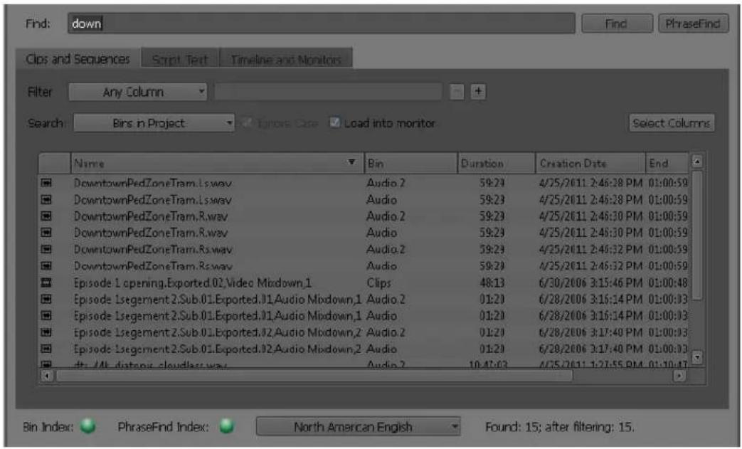
To resize the Results window:
▶Click and drag the corner of the window to enlarge or reduce the size of the window.
The window adjusts. If you enlarge the window, more results display in the Results window.
To display columns:
- Click Select Columns.
The Click column names to select dialog box opens.

The default columns are pre-selected (Bin, Name, Duration, Video, Creation Date, Start, End, Tracks, Mark IN-OUT, IN-OUT). The Icon, Name and Bin columns always display. The Score column always display in PhraseFind.
Column selections reset from search to search. The system does not remember columns you have previously selected.
- Click the columns you want to display in the Results window.
You can deselect the default columns.
- Click OK.
The columns you selected appear in the Results window.
To move columns:
In the Results window, click and drag a column heading.
The column moves to the new location.
To sort a column:
Click a column heading to sort the results in ascending or descending order based on that column.
The column reformats. You can sort all columns. After you click a column heading, the ascending or descending icon appears.
To load a clip in the Source monitor:
▶Click Load into monitor.
When you double-click a clip in the Results window, the clip opens in the Source monitor. To open multiple clips, you need to double-click each clip in the Results window to open in a Source pop-up monitor.

Loading the clip in the Source monitor is dependant on the option you have chosen for "Double-click loads object in" in your Bin Settings.
Filtering Your Find Results
You can narrow your search results to display less results. This is achieved by selecting specific columns and additional criteria. You need to perform a find before columns appear to filter.
For example, if you are looking for a clip with the name of Scene 2c and a duration of 03:00:00. The initial result displays fifty items, you can filter the search by selecting Name as the column and enter 2 in the contains field. In the second filter, select Duration as the column and enter 3 in the contains field. As you enter each filter, the results get fewer and fewer.

If the audio you are searching for is in a specific bin, after you receive your initial results, select Bins from the Filter menu and then enter the Bin name.
To filter a search:
- After you perform a text find or PhraseFind, select a specific column from the Filter menu that you would like to search in and enter additional text criteria.

You need to perform a find before columns display in the Filter menu.
As you enter the text criteria, the results start to update and less results appear in the window based on your criteria.
- Click the “+” button to add additional filters.
A new row appears, enter additional rows and text criteria.
- Click the “-” button to remove filters.
The filter row is removed, and displays your last filter.
If the last filter appears, the system removes the text criteria and the column selection and leaves the filter.

The system saves your last find. If you close and reopen the Find window, the last find you perform is saved in the Results window.
Find Window Attributes
The following table describes the attributes available in the Find window for PhraseFind and text find.
Results Window Attributes Description
Find: Allows you to enter your search text criteria.
Results Window Attributes Description
Find Click this button when you enter text in the textbox and you are ready for the system to search for your alphanumeric results.
PhraseFind Click this button when you enter phonetic text in the textbox and you are ready for the system to search for your audio dialogue results.
Cancel The Cancel button appears once you click either the Find or PhraseFind button. This cancels the search.
Clips and Sequences Select this option if you want the system to search through your clips and sequences. The system does not search and find referenced clips in a sequence. Then choose to search in the current bin and script opened in your project or all bins and scripts in the project regardless if they are opened or not.
Script Text Select this option if you want the system to search through your scripts. Then choose to search in the current script opened in your project or all scripts in the project regardless if they are opened or not. (text find only).
Timeline and Monitors Select this option if you want the system to search through the Timeline and monitors. Then choose to search for text in Markers, Clip Names, and Timeline Text. (text find only).
Settings Select the option if you want to change the location of the Search Data Folder or if you want to stop or start the Find or PhraseFind indexing.
Filter Allows you to select a specific column to search in from a menu, then enter additional text to help narrow your search results.
+ or - Allows you to add (+) or remove (-) filters
Ignore Case Select this option if you want the search to find results whether the text is lower or upper case text.
Load into monitor Loads the clip in the Source monitor when you double-click the clip in the Results window.
Whole words only Available when you select Current Script. Select this option when you only want to find that word. For example with this option selected, if you enter “eat,” the system will only find eat. Not eating, eats, neat.
Results Window Attributes Description
| Select Columns Opens a dialog box which allows you to select columns to display in the Results window. | |
| Language menu Allows you to select a language from the languages you have licensed on your system (language packs are purchased separately.) | |
| PhraseFind Index and Bin Index | Displays the status of your indexed files. Full green indicates that your data files have been indexed and are ready to search. Partial green indicates that the index is in process and if you perform a search, your results might not be complete. |
| Found Displays the total number of results found after your search. | |
| after filtering Displays the total number of results found after you filter. | |
14 Creating and Editing Sequences
This chapter introduces you to procedures that you use to build a sequence, as described in the following topics:
- Entering Source/Record Mode
- Creating a New Sequence
- Making a First Edit
- Creating an Instant Rough Cut
- Undoing or Redoing Edits
- Editing Additional Clips into the Sequence
- Mixing Frame Rates and Field Motion Types
- Mixing Frame Sizes and Aspect Ratios
- Refreshing Sequences to Use Current Clip Attributes
• Lifting, Extracting, and Copying Material - Adding Comments to Sequence Clips
- Playing Back a Sequence
• Understanding Sync Breaks - Fixing Sync Breaks
• Understanding Sync Lock
• Ganging Footage in Monitors - Sync Point Editing
- Autosyncing Clips
• Understanding AutoSequence - Resyncing Subframe Audio
- Resyncing Audio for a Selected Subclip
• Working with Phantom Marks - Creating Video and Audio Leaders
- Adding Audio or Video to Original Videotape Using AutoSequence
Entering Source/Record Mode
Source/Record mode is the default editing mode. It includes the screens and controls used for the Source and Record monitor. Use Source/Record mode to create new sequences from source clips.
To enter Source/Record mode from another mode:

▶Click the Source/Record Mode button.
Depending on the model of your Avid editing application, the Source/Record Mode button might appear in a default location, for example, in the second row of buttons below the monitors. You can map the Source/Record Mode button to any mappable button location, or use it directly from the Command Palette. For information about mapping buttons, see “Mapping User-Selectable Buttons” on page 112.
For more information about the Composer window, see “Customizing the Composer Window and Monitors” on page 488.
Creating a New Sequence
You can create a new sequence in one of two ways, depending on the requirements of your workflow:
- To set specific parameters for the sequence before you start editing, you can use the New Sequence command to create and name a sequence, set the start timecode, (see “Changing the Name and Timecode for a Sequence” on page 577) and determine the numbers and types of tracks (see “Track Display for New Sequences” on page 579) to use before you make the first edit.
- To begin editing right away and build the sequence as you go without setting parameters ahead of time, you can create the sequence automatically by making an initial edit, as described in “Making a First Edit” on page 581.
To create a sequence with the New Sequence command:
- Do one of the following:
▶Select Clip > New Sequence.
▶ Right-click in either the Timeline or the Source/Record monitor, and select New Sequence.
One of the following occurs:
- If just one bin is open or you activate a bin, the new sequence appears in that bin. It also appears in the Record monitor and in the Timeline, with the generic title “Untitled Sequence n.” Each new sequence is numbered incrementally until you rename it.
- If a bin is not activated, the Select dialog box opens.
Select the bin where you want to store the new sequence, or click New Bin to create and open a new bin, then click OK.
An untitled sequence appears in the bin, in the Record monitor, and in the Timeline.
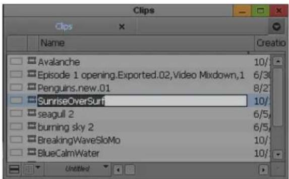
- (Option) In the bin, click the Name field and rename the new sequence.
Changing the Name and Timecode for a Sequence
To rename a new sequence and set a start timecode:
- Do one of the following:
From a bin, right-click a sequence and select Sequence Report. You can select multiple sequences for generating reports.
With a sequence loaded in a monitor, right-click the monitor and select Sequence Report.
The Sequence Report dialog box opens.
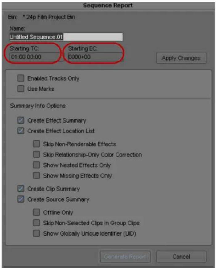
Start timecode text box (left) and Start key number text box (right, for 24p or 25p projects only) in the Sequence Report dialog box
- Type a new name in the Name text box.
- Drag the pointer across the start timecode (Starting TC) to select it, and type a new timecode.
You need to type only the first colon (non-drop-frame timecode) or semicolon (drop-frame timecode). For example, type 01:000000 for 01:00:00:00. For information about non-drop-frame and drop-frame timecode, see “Understanding Timecode” on page 183.
- For film projects, select the start key number (Starting EC) and type a new start key number.
- Click Apply Changes.
- Click OK.
You can also change the default start timecodes for all new sequences by using General settings. For more information, see “General Settings” on page 1411.
To change the start timecode of a sequence in a bin:
- In the bin, click the start time for the sequence in the Start column.
- Type a new timecode.
Track Display for New Sequences
When you create a new sequence with the New Sequence command and no material is loaded in the Source monitor, the Timeline displays a default set of tracks—the master timecode track (TC1), at least one video track (V1), and at least two audio tracks (A1 and A2). For film projects, the output timecode format tracks and EC (edgecode) track also display.
You can change the initial set of tracks that display in the Timeline in the Edit tab of the Timeline Settings dialog box. For more information, see “Timeline Settings: Edit Tab” on page 1437.
You can add up to 24 audio or video tracks to a sequence. For more information, see “Adding and Deleting Tracks” on page 716. You can also add one Data (D1) track for ancillary data (closed captioning). For more information, see “Preserving HD Closed Captioning and Ancillary Data” on page 1091.
The following illustration shows the default Timeline for a new sequence, with no material loaded in the Source monitor.

User Preferences for Creating Tracks
There are two options in the Edit tab of the Composer Settings dialog box that help automate the way you create and enable tracks. You can adjust these settings in advance, based on personal preference.
For information on opening and changing settings, see “Viewing and Modifying Settings” on page 1339.
The default settings are:
- Auto-create New Tracks: Whenever you edit new source material from the Source monitor, the system automatically creates any new tracks in the sequence that match enabled tracks on the source side.
- Auto-enable Source Tracks: Whenever you load new source material into the Source monitor, the system automatically enables all existing source tracks.
Alternatively, you can do the following:
- Deselect Auto-create New Tracks to have the existing tracks in the sequence remain the same when you edit in new source material. This lets you create new tracks selectively as you edit.
- Deselect Auto-enable Source Tracks to leave the tracks of newly loaded material in whatever state they were in when they were last loaded. This lets you turn on the source tracks more selectively as you edit.
Adding Filler
You can add a small amount of black filler at the start of your sequence. A brief moment of black before the start of your sequence is sometimes useful during playback or when recording a digital cut. You can also add filler to another part of the sequence at any time during editing.

You cannot add filler to the end of a sequence or to an empty sequence. You can create black title media and insert it at the end of a sequence. For information about creating title media, see “Creating Titles” in the Help.
To add filler at the start of a sequence, do one of the following:
▶Select Clip > Add Filler at Start.
▶Right-click in the Timeline, and select Add Filler at Start.
Filler appears at the beginning of the sequence in the Timeline. You can set a default duration for the filler in the Edit tab of the Timeline Settings dialog box. For more information, see “Timeline Settings: Edit Tab” on page 1437.
To add filler anywhere in a sequence:
- Click above the Source monitor, and select Load Filler from the Clip Name menu.
The system loads a 2-minute clip of filler into the Source monitor. - Mark the amount of filler that you want to add.
For more information, see “Marking IN and OUT Points” on page 518. - Do one of the following:
▶ Move the position indicator for the sequence to the point where you want to add the filler.
Mark an In point at the point in the sequence where you want to add the filler.
- Click the Splice-in or Overwrite button to edit the filler into the sequence.

Splice-in button (left) and Overwrite button (right)
For more information, see “Performing an Insert or Splice-in Edit” on page 584 and “Performing an Overwrite Edit” on page 585.
Making a First Edit
This topic describes a method for adding a first clip to a sequence. You can use this method after you create a new sequence, as described in “Creating a New Sequence” on page 576. You can also use this method without creating a new sequence in advance, in which case the sequence is created as soon as you make the edit.
To begin editing:
- Load the first clip into a monitor.
For more information, see “Loading and Clearing Footage” on page 503.
- (Option) If you have not already marked In and Out points for the clip in advance or created a subclip, view and mark the clip.
For more information, see “Marking and Subcataloging Footage” on page 518.
- Click buttons in the Track Selector panel to select the tracks you want to include in the edit.
Only the tracks that you capture for the clip appear as source tracks in the Timeline. For more information on using the Track Selector panel, see “Understanding the Track Selector Panel” on page 707.

Source tracks in the Track Selector panel
For example, with a talking head you might select tracks V1 (picture) and A2 (sound) if the voice was recorded on that track. You would deselect track A1, that might have unwanted wild sound picked up from a second microphone or no sound at all.
As another example, if you lay down a music track first, you would select track A1 or A2 depending on where the music was recorded, and deselect V1.

- Click the Splice-in button to add the edit to the sequence in the Record monitor.
The Record monitor displays the end of the last frame of the new edit. (You can drag the position indicator in the Timeline or the position bar beneath the monitor to review the clip.) The edit also generates a graphical display of the cut in the Timeline.

Screen display for the first edit in a sequence. Top: monitor window with the source clip on the left and the sequence on the right. The Splice-in button and the indicator of the end of the last frame for the edit are highlighted. Bottom: the new edit in the Timeline.
Creating an Instant Rough Cut
As an alternative to creating a new sequence by editing clips one at a time, you can create a rough cut by creating a storyboard in the bin, and then load these clips directly into the Timeline.
For additional information on editing directly from the bin into the Timeline, see “Bin Editing into the Timeline” on page 705.
To create a rough cut from a bin:
- In the bin, sort the clips in the order in which you want them to appear in the sequence.
For example, in Frame view, arrange the bin so that you can drag clips into the storyboard order you want. - Select the tracks for the edit.

If no sequences are loaded in the Record monitor, the Timeline has no features.
- Do one of the following:
▶Ctrl+click (Windows) or Command+click (Macintosh) the clips.
Lasso the clips by dragging left to right and down to select more than one clip. For more information, see “Selecting Clips and Sequences” on page 335.
▶Select Edit > Select All if there are no other clips in the bin.
- Do one of the following:
Drag the selected clips to the Timeline to splice the clips into place.
▶ Shift-drag the selected clips to the Record monitor.
▶Alt-drag (Windows) or Option-drag (Macintosh) the selected clips to the Record monitor.
The clips splice together to form a new sequence based on the order in which they were listed in the bin.
Undoing or Redoing Edits
You can undo or redo up to 100 previous actions listed in the Edit menu. You can undo or redo a just completed command, or you can search through a submenu to undo or redo all commands leading back to a particular command.

Undo and Redo commands in the Edit menu. Top: the Undo/Redo command for the previous edit. Bottom: the Undo/Redo List command. In the Undo/Redo List submenu, prior Redo commands appear in the upper part of the submenu, and prior Undo commands in the lower part.
You can limit the Undo function to undo only record actions by selecting the Undo Only Record Events option in the Edit tab of the Composer Settings dialog box.
For example, you can select the Undo Only Record Events option and then mark several In and Out points in clips loaded in the Source monitor. If you decide to undo the last edit made to the sequence, then you would not lose the In and Out points in the source clips.
To undo only the previous edit or function, do one of the following:
▶Select Edit > Undo.
▶Press Ctrl+Z.
To redo only the previous edit or function, do one of the following:
▶Select Edit > Redo.
▶Press Ctrl+R.
To undo or redo every edit and function back to a particular command:
▶Select Edit > Undo/Redo List, and then select a command.
All the previous commands, including the command selected from the submenu, are undone or redone
Editing Additional Clips into the Sequence
There are three primary edit functions for adding material to your sequence:
- Insert (splice-in)
• O v e r w r i t e
- Replace edit
In most cases, you perform three-point edits in which you set three marks—two in the source material and one in the sequence, or the reverse. The fourth mark is determined automatically. The way you set marks depends on the type of edit you perform.
You can use two marks or sometimes one mark to complete an edit using phantom marks. For more information, see “Working with Phantom Marks” on page 620.
Performing an Insert or Splice-in Edit
An insert or splice-in edit inserts marked source material into the sequence without replacing material already in the sequence.
Existing material moves beyond the spliced material, lengthening the overall duration of the sequence.

A splice-in edit. Clip 3 in the sequence moves down when you splice clip 4 in at the insertion point (red line).
To perform an insert edit:
- Load a clip into the Source monitor.
- Mark an In point and an Out point.
- Mark an In point in the sequence as follows:
a. Move the position indicator for the sequence to the point where you want to splice the clip into the sequence.
b. Click the Mark In button, or press the Mark In key.

If you do not mark an In point, the system splices the new clip into the sequence at the current location of the position indicator.

- Click the Splice-in button (yellow) to complete the edit.
Performing an Overwrite Edit
An overwrite edit replaces a section of the sequence with the selected source material.
An overwrite edit replaces existing material and does not lengthen the overall duration of the sequence unless the material used to overwrite goes beyond the end of the sequence.

An overwrite edit. Clip 4 overwrites parts of clips 2 and 3 (shaded in red) when you edit it in at the insertion point (red line).
To perform an overwrite edit:
- Load a clip into the Source monitor.
- In the monitor, mark an In or Out point, but not both, to show the start or end of the clip you want to use.
-
In the Record monitor, mark both an In point and an Out point to select the material in the sequence you want to overwrite.
You can also mark an Out point and move the position indicator to the In point. -
Click the Overwrite button (red) to complete the edit.
Performing a Replace Edit
The Replace Edit button (blue) replaces a clip in the sequence (video, audio, or both) with new source material, while maintaining the original In and Out points of the previous edit.

A replace edit. Clip 4 replaces clip 3 and maintains the IN and OUT points for the original edit.

By default, the Replace Edit button is located on the Edit tab of the Command Palette. You can use it from the Command Palette or map it to a monitor palette. For information about mapping buttons, see “Understanding Button Mapping” on page 110.
Sync Point editing, which is similar to replace editing, lets you overwrite material in the sequence based on the alignment of position indicators in the source material and in the Timeline. The difference is that Sync Point edits end at the nearest marks in either the source or record material, and replace edits always fill the In to Out portion of the clip in the sequence. For more information on sync point editing, see “Sync Point Editing” on page 614.
To perform a replace edit:
- Move the position indicator to select a sync frame in the source clip.
The frame displays in the monitor.
The sync frame can be an In point, Out point, or any frame in between that you want to sync to a frame in the existing clip in the sequence.
-
Move the position indicator to select the sync frame in the sequence for the edited segment that you want to replace.
-
Click the Replace Edit button (blue).
-
Move the position indicator to select the sync frame in the sequence for the edited segment that you want to replace.
- Click the Replace Edit button (blue).

The system calculates In and Out points for the source material by using the sync frames and the existing In and Out points in the sequence for the previously edited clip that you want to replace.

When you select the tracks you want, check the durations before you perform the edit. If you replace a clip in an overlap edit and the position indicator falls within the overlap, you might end up replacing the wrong material unless you select the entire segment you want to replace. See “Selecting and Deselecting Segments” on page 694.
Enabling Single-Mark Editing
Single-mark editing lets you establish a single mark, and then use the location of the position indicator to determine the second mark when making the edit. You can use this procedure in several ways to save steps:
- You can mark an In point in the Source monitor and then perform a splice-in, overwrite, or replace edit without marking an Out point.
- You can mark an Out point, locate a frame for the In point, and then perform the edit without marking the In point.
- You can mark the In or Out point, play, step (jog), or shuttle through the clip forward or backward, and then press the Splice-in, Overwrite, or Replace Edit button to perform the edit on-the-fly without adding the second mark.
To enable single-mark editing:
- In the Project window, click the Settings tab.
- Double-click Composer.
The Composer Settings dialog box opens. - In the Edit tab, select Single Mark Editing.
- Click OK.
Mixing Frame Rates and Field Motion Types
You can work with clips of any frame rate or field motion type (interlaced or progressive) in a project, regardless of the project's type. For example, you can work with 30i clips in a 24p project. In your Avid editing application and in this documentation, clips that do not match the frame rate or field motion type of the project are known as mixed rate clips.
You can view and play mixed rate clips in the Source monitor or in pop-up monitors. You can also edit mixed rate clips into a sequence.
Mixed rate clips always play at the project's frame rate, both in Source or pop-up monitors and in sequences. Audio remains synchronized with video. You can stack clips with different frame rates or field motion types on multiple video tracks, apply effects, and otherwise perform all normal editing operations.
How Your Avid Editing Application Handles Mixed Rate Clips
Motion Adapter Effects
Your Avid editing application uses Motion Adapter effects to handle:
- Clips that have a different frame rate from the project's frame rate
- Clips with field motion that need adjustment to be compatible with the project
- Clips with 2:3 pulldown or strobe frames
Motion Adapter effects allow mixed rate clips to play at the project's frame rate and to have the correct field motion.
Motion Adapter effects are different from other effects in several ways:
- You do not apply Motion Adapter effects manually. The Motion Adapter effect does not appear in the Effect Palette and does not have an effect icon. Your Avid editing application applies Motion Adapter effects and sets their parameter values automatically.
- Your Avid editing application applies Motion Adapter effects when they load into a Source or pop-up monitor for viewing and playing as well as when they are edited into a sequence.

If you load a traditional (source-side) motion effect that has a different frame rate from the project's frame rate, it is automatically promoted. In the case of Strobe Motion effects, the update rate of the strobe motion is adjusted so that the effect maintains the same look at the project's frame rate.
- You cannot remove a Motion Adapter effect that adjusts the speed of a clip with the Remove Effect button. If you promote a Motion Adapter effect to a Timewarp effect and then use the Remove Effect button to remove the Timewarp, your Avid editing application re-applies a Motion Adapter effect.
- You often do not need to adjust Motion Adapter effects. Most of the time, they work automatically and seamlessly to allow mixed rate clips to play correctly in a project. For information on when you might want to adjust a Motion Adapter effect and on how to do so, see “Viewing and Adjusting Motion Adapter Parameters” on page 590.
You might need to provide accurate frame layout information for a clip, such as its field motion or whether it contains pulldown. For information on how to do this, and more details of the circumstances that might require it, see “Modifying the Field Motion Attribute for a Clip” on page 592.
User Interface Summary for Mixed Rate Clips
Illustration Description


In the Timeline, several visual indicators highlight mixed rate clips. For more information, see “Viewing Mixed Rate Clips in the Timeline” on page 590.
In the Motion Effect Editor, you can view the parameter values for a Motion Adapter effect, and adjust the render type. To make further adjustments, you need to promote the Motion Adapter effect to a Timewarp effect. For more information, see “Viewing and Adjusting Motion Adapter Parameters” on page 590.

In the bin, the Field Motion column provides field motion and frame layout information for a clip. Motion Adapter effects use the Field Motion attribute value to determine their Source parameter value. For more information, see “Modifying the Field Motion Attribute for a Clip” on page 592 and “Refreshing Sequences to Use Current Clip Attributes” on page 601.

In the Modify dialog box, set a new format for a sequence to create a version of the sequence that plays at a different rate from its original rate. You can then work with that sequence in a project that uses the new frame rate. For more information, see “How Your Avid Editing Application Reformats Clips in Sequences” on page 596 and “Changing the Sequence Format” on page 1515.
Viewing Mixed Rate Clips in the Timeline
Mixed rate clips that are unrendered always appear with a green dot that represents the Motion Adapter effect, the green dot appears on mixed rate clips edited into a sequence. If you use the Toggle Source/Record button to view the Timeline for a mixed rate clip loaded in the Source monitor, you also see the green dot on that clip.
Mixed rate clips also display with their original frame rate appended to the clip name. For example, if you have a 24 fps clip named sunset that you edit into a sequence with a frame rate other than 24 fps, the clip name displays as sunset (24.00 fps).
The illustration shows a mixed rate clip in the Timeline.

To further distinguish mixed rate clips from other material in the Timeline, you can display them in distinct colors. For more information, see “Displaying Clip Colors in the Timeline” on page 672.
Viewing and Adjusting Motion Adapter Parameters
Use the Motion Effect Editor to view and adjust parameters for a Motion Adapter effect.
To change the appearance of a mixed rate clip, you can select a different rendering option from the Type list to change the way your Avid editing application interprets and displays frames.
The other Motion Adapter effect parameters are inactive. You can check the values your Avid editing application has calculated, but you cannot change them.
If you need to make other adjustments, promote the Motion Adapter effect to a Timewarp effect. The full set of Timewarp effect parameters become available and you can freely change or animate the speed at which the clip plays.
The illustration shows the Motion Adapter effect in the Motion Effect Editor, with the Type list and the Promote button active, and other parameters inactive.


In some circumstances, the Adaptive Deinterlace Source option is active in the Motion Effect Editor for a Motion Adapter effect. Adaptive deinterlacing is a processing option that can improve the look of interlaced source material that is being converted to progressive frames. For more information, see “Using Adaptive Deinterlacing” in the Help.
To view parameter values for a motion adapter and adjust the render type:
- Move the position indicator to the mixed rate clip that uses the Motion Adapter effect you want to adjust.
- Click the Motion Effect button.
The Motion Effect Editor opens and displays the current parameter settings for the Motion Adapter effect.
The system displays the current parameter values for the adapter. If you have not yet made any manual adjustments to the adapter, the values you see are those your Avid editing application created automatically. For example, you see a Speed percentage value that adjusts the clip's speed to the project's rate.
The Type list (render options) is active. The Adaptive Deinterlace Source option might also be active. Other parameters are inactive.
- Select a rendering option from the Type list.
For information on the rendering types available, see “Rendering Options for Timewarp Effects” in the Help.
To promote a motion adapter to a Timewarp effect
- Move the position indicator to the mixed rate clip that uses the motion adapter you want to adjust.
- Click the Motion Effect button.
The Motion Effect Editor opens.
- Click the Promote button.
The motion adapter is promoted to a Timewarp effect and all standard Timewarp effect parameters are available.
- Adjust the Timewarp parameters as necessary to create the motion that you want for the clip.
Modifying the Field Motion Attribute for a Clip
The Field Motion bin column contains information about the frame layout of a clip or subclip. It indicates whether the clip is interlaced or progressive, or whether it contains 2:3 pulldown or repeated (strobe) frames. The Field Motion attribute sets the default Source parameter value for the Motion Adapter effect.
When you create a clip or subclip, its Field Motion attribute is set to either Interlaced or Progressive, depending on the project type. In most cases this value accurately represents the field motion of the clip or subclip, but you sometimes need to override the value to match the actual field motion of the video source or to indicate that the source contains 2:3 pulldown or repeated frames.
The illustration shows the Field Motion bin column and the menu that lets you change the Field Motion attribute value.

Changes you make to the Field Motion attribute apply only to the individual clip or subclip. You can have several subclips derived from the same master clip, and set different Field Motion values on each of them.
When you change the Field Motion attribute of a clip, it updates if it is loaded in a Source or pop-up monitor, and new edits into a sequence from the clip use the new Field Motion attribute value. However, edits that you made from that clip before you change the Field Motion attribute continue to use the old value. If you want to update a sequence so that all its Motion Adapter effects use the current Field Motion attribute values for their source clips, refresh the Motion Adapter effects for the sequence. For more information, see “Refreshing Sequences to Use Current Clip Attributes” on page 601.
To modify the Field Motion attribute for a clip or subclip:
- Open the bin that contains the clip or subclip you want to modify.
For more information, see “Opening and Closing Bins” on page 74.
- (Option) If it is not already visible, display the Field Motion bin heading.
For more information, see “Using Text View” on page 325.
- Click the Field Motion item for the clip or subclip, and select one of the following:
Option Description
Interlaced Use for all video with interlaced field motion.
2:3 Film Only available for clips or subclips created in 30 fps projects.
Use for a clip or subclip that contains 2:3 pulldown.
Video material can contain pulldown frames in a number of circumstances, such as the following:
- The telecine process inserts pulldown frames when it transfers film footage shot at 24 fps to 30 fps video.
- Some cameras can shoot at 24 fps but record at 30 fps, and insert pulldown frames to achieve the record frame rate.
- Some HD video decks insert pulldown frames when downconverting material, for example, from 1080p/24 to NTSC 30i.
Progressive Use for progressive video.
Progressive Strobe Use for a clip or subclip that contains repeated frames, for example, a traditional strobe motion effect clip, or a clip where the original video was shot at a reduced frame rate such as 15 fps.
Usually results in a better finished look because blending between frames reduces stuttering motion.
Considerations When Working with Mixed Rate Clips
Playback of Mixed Rate Material with Different Frame Sizes
When your mixed rate sequence includes clips of different frame sizes, consider using the High-Quality Scaling for Real-Time Decode setting. This setting improves image quality during playback of mixed-format sequences where material requires resizing. For more information, see “Video Display Settings” on page 1441.
Playback of Mixed Rate Material Using XDCAM AMA Media
Playback limitations when you work with XDCAM AMA media on an optical disk are particularly noticeable with mixed rate sequences or with mixed rate clips loaded into the Source monitor. Consider consolidating the media to a local disk. For more information, see “Using XDCAM and XDCAM EX and XDCAM SR AMA Plug-Ins” on page 398.
Behavior of Mixed Rate Material at Different Video Quality Settings
Be aware of the following if you work with mixed rate clips when you use the Draft Quality, Best Performance, or DNxHD Native video quality options:
- You do not see an accurate pulldown cadence when you field-step through material where pulldown is inserted. This is a limitation of Timewarp and Motion Adapter effects when you work in draft qualities. If you switch to Full Quality, or render the Motion Adapter effects, the pulldown cadence is correct.
- Playback of clips whose frame rate do not match the sequence frame rate might be jumpy when you use Draft Quality. To achieve smooth playback, you can either use Full Quality or render the motion adapters for the relevant clips.
Transcoding Mixed Rate Material
You can transcode clips of any edit rate, including clips that you have edited into a sequence, to any resolution available within your current project.
You might need to transcode mixed-rate material as part of common workflows like offline/online conversion or creation of a QuickTime reference movie. You also might want to transcode mixed-rate material in order to homogenize your sequence and transfer it to an editing application that cannot conform mixed-rate sequences, such as an Avid DS version older than 10.3, or an older Media Composer application. You can also use transcoding for general clip conversion tasks such as removing 2:3 pulldown from 29.97i sources (to generate 23.976 sources), or generating NTSC material from a PAL source.
Once the transcode process completes, you can edit with the clips directly, or you can batch capture or import if you have access to original sources at the new rate. The transcoded material uses the project's edit rate, so the new clips no longer require motion adapters when you edit
them into sequences in the same project type. When existing material in a sequence is transcoded across edit rates, your Avid editing application automatically removes motion adapters and adjusts Timewarp effects.
Your Avid editing application creates new clips whose duration and start and end timecode matches the original clips as closely as possible and which are as compatible as possible with the project's edit rate. However, due to roundoff error, you might see minor variations in clip duration or in frame offset information that could result in such issues as minor audio/video differences (for example, slips of 1 or 2 frames).
In some cases, the last frame of a transcoded clip might be offline. Avid recommends using non-zero handles when you transcode sequences with mixed-rate clips to minimize the chance of seeing offline frames.
You should check transcoded sequences carefully and adjust any variations from the original sequences that are not acceptable to you, for example, by trimming.
You cannot transcode clips across edit rates using the Transcode Server in Interplay.
Grouped Clips and Mixed Rate Material
Be aware of the following if you group clips or work with grouped clips:
- You cannot group clips that have different frame rates
- You cannot load a grouped clip whose frame rate does not match the project's frame rate. If you load this type of clip into the Source monitor or drag it into the Timeline, an error message appears.
- You can create a sequence that includes both grouped clips that have the same frame rate as the project and single clips of other frame rates.
Working with Markers on Mixed Rate Material
You should be aware of the following when you work with markers on mixed rate material:
- Depending on the frame rates of your clips and your project, you might not be able to add a marker at the exact location of the position indicator. For example, if you add a marker to a 30 fps clip in a 720p/59.94 project, you can move the position indicator to a location that does not match a frame in the clip. Your Avid editing application adds the marker at the closest valid location in the clip.
- Depending on the frame rates of your clips and your project, you might not be able to access all of the markers on a clip in the Source monitor. For example, if you load a 720p/59.94 clip in a 30 fps project, the position bar in the Source monitor cannot display every marker position. You can use the Markers Window to access all the markers. For more information, see “Using the Markers Window” on page 531.

Effect Templates and Mixed Rate Material
You can use effect templates that you save in bins with clips of all frame rates and in sequences of any project type. When you apply a template, your Avid editing application adjusts keyframes if necessary to account for differences in frame rate.
Dynamic Relink and Mixed Rate Material
You can enable the Dynamic Relink feature to work with mixed rate clips. However, Dynamic Relink behaves slightly differently when it operates on clips that do not match the frame rate of the project. For more information, see “Using Dynamic Relink with Mixed Rate Clips” on page 1272.

Motion adapters do not conform in versions of Avid DS prior to version 10.3. You cannot play or adjust mixed rate material in these versions. Do not include mixed rate clips in sequences that you intend to finish on an Avid DS system running an older version of Avid DS than version 10.3.
Mixing Frame Sizes and Aspect Ratios
You can work with media of different frame sizes, aspect ratios, and pixel aspect ratios in the same sequence. For example, you can mix SD 4:3, HD 16:9, and film formats.
How Your Avid Editing Application Reformats Clips in Sequences
Your Avid editing application reformats a clip in a sequence when the aspect ratio, pixel aspect ratio, or frame size of the clip do not match those of the project. Your Avid editing application automatically resizes and repositions these clips to match the project's format settings.
You need to ensure that your project's format settings are set correctly so that clips are reformatted properly. For more information, see “Creating a New Project” on page 50 and “Changing the Aspect Ratio for a Project” on page 597.
When you change a format setting, for example, the aspect ratio for an SD project, all clips currently edited in a sequence immediately adapt to the new format. You do not need to re-edit any clips in your sequences. When you next view the sequence, you see any changes to the size and position of clips.
By default, your Avid editing application reformats clips to fill the frame by stretching. You can set other reformatting options by changing the Reformat attribute for that clip in the bin. For more information, see “Modifying the Reformat Attribute for a Clip” on page 598.
Changing the Aspect Ratio for a Project
You typically set the aspect ratio for a project when you create the project (see “Creating a New Project” on page 50). The aspect ratio can be changed at any time, however this will affect any titles that you have created, so the titles also need to be recreated at the new aspect ratio.

For HD projects, only the 16:9 aspect ratio is available as this is the only aspect ratio allowed in the HD standard.
To change the aspect ratio for a project, do one of the following:
Click the Format tab in the Project window, then click the Aspect Ratio menu, and select either 4:3 or 16:9, depending on the aspect ratio you want to use.
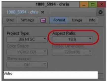
Aspect Ratio menu in the Format tab of the Project window
Right-click in the monitor window in Source/Record or in Trim mode, select Project Aspect Ratio, and then select either 4:3 or 16:9, depending on the aspect ratio you want to use. Right-click in the monitor window in editing or in Trim mode, select Project Aspect Ratio, and then select either 4:3 or 16:9, depending on the aspect ratio you want to use.
Your Avid editing application changes the aspect ratio of the monitors, and resizes and repositions any material in the project's sequences that does not match the new aspect ratio so that it conforms to that aspect ratio. You see these changes when you next open and view an affected sequence. You do not need to re-edit the media into the sequence, and the source media remains unchanged.
To recreate titles at the new aspect ratio:
- After you have switched to the new aspect ratio, select a clip on the timeline that has a title that you need to recreate.
- From the main menu, select Clip > Recreate Title Media.
A new title will be recreated in the bin with the new aspect ratio.
- Continue recreating all other titles on your timeline using the same steps.
Modifying the Reformat Attribute for a Clip
Your Avid editing application uses the Reformat attribute of a clip to resize and reposition the clip so that it conforms to the current frame size and aspect ratio specified in the Project Settings. When you create a clip or subclip, the Reformat attribute is automatically set to Stretch. If you are using AMA to link to clips, then the default is set to Center Keep Size.
You can modify this Reformat attribute at any time. Reformat options apply only when a clip does not match the project aspect ratio. For a list of these options, see “Reformatting Options Reference” on page 599.

If you are working in an Interplay environment, do not change the Reformat attribute from the Stretch setting. If you use a different setting, and you then use Interplay Transcode or Send to Playback, the results might not be what you expect.
The illustration shows the Reformat bin column and the menu that lets you choose a Reformatting Option.

Changes you make to the Reformat attribute apply only to the selected clip in the bin. You can have several subclips derived from the same master clip, and set different Reformatting Options on each of them.
When you change the Reformat attribute of a clip, it updates if it is loaded in a Source or pop-up monitor, and new edits into a sequence using this clip use the new Reformatting Option. However, previous edits using this clip continue to use the old value. If you want to update a sequence so that all versions of this clip in a sequence use the current Reformat attribute, refresh the Reformatting Options for the sequence. For more information, see “Refreshing Sequences to Use Current Clip Attributes” on page 601.
To set the Reformat value for an individual clip or subclip:
- Open the bin containing the clip or subclip you want to modify.
For more information, see "Opening and Closing Bins" on page 74.
- Click the Text tab.
- (Option) If it is not already visible, display the Reformat bin heading.
For more information, see "Using Text View" on page 325.
- Click the Reformat field for the clip or sub-clip, and select an option.
Options apply only to clips that do not match the frame size and aspect ratio of the project.
For more information, see “Reformatting Options Reference” on page 599.
Reformatting Options Reference
The table describes the choices available under the Reformat bin heading and their effect when you edit a clip into a sequence of a different size or aspect ratio. These options have no effect on clips that do match the project size and aspect ratio. For information on how to set the reformatting options for a clip, see “Mixing Frame Sizes and Aspect Ratios” on page 596.

In all reformatting options, the center of the source material is set by default to the center of the sequence frame. You can reformat the clip manually by using the "Center Keep Size" reformatting option and then using the Resize effect to modify the position of a clip after you edit it into a sequence.
Option Description
Stretch Scales the clip to match the width and height dimensions of the sequence. If the clip's aspect ratio does not match the sequence's aspect ratio the image is distorted (stretched or squeezed).
The illustration shows an example where a 4:3 clip is placed in a 16:9 sequence. The clip is stretched horizontally to accommodate the width of the sequence.

natural_image
Interior view of a grand, ornate dome ceiling with intricate carvings and a central circular skylight (no visible text or symbols)
natural_image
Interior view of a grand, ornate dome with a central circular ceiling and symmetrical seating (no visible text or symbols)Option Description
Pillarbox/Letterbox preserve aspect ratio
Scales the clip to create the largest possible image without cropping, while maintaining the original aspect ratio.
The illustration shows two examples. When you edit a 16:9 clip into a 4:3 sequence (left), the resulting segment has horizontal bars at the top and the bottom. When you edit a 4:3 clip into a 16:9 sequence (right), the resulting segment has vertical bars at the sides.

natural_image
Coastal scene with a lighthouse on rocky shore and waves crashing against the sea (no text or symbols visible)Center crop, preserve aspect ratio

natural_image
Interior view of a grand, ornate dome with a central circular skylight and symmetrical golden-rimmed ceiling (no text or symbols visible)Scales and crops the clip to be the smallest size possible while filling the entire frame. The resulting image is centered in the frame.
The illustration shows two examples. When you edit a 16:9 clip into a 4:3 sequence (left), the resulting segment is cropped at the sides. When you edit a 4:3 clip into a 16:9 sequence (right), the top and the bottom of the segment are cropped.

natural_image
Coastal scene with a lighthouse on rocky shore and waves crashing near the coastline (no text or symbols visible)
natural_image
Interior view of a grand, ornate dome with a central circular structure and golden chandelier (no visible text or symbols)Center, keep original size Centers the clip in the sequence but does not resize it. If the source clip is not the same size as the sequence, the clip is either cropped or does not cover the whole of the sequence frame.
Refreshing Sequences to Use Current Clip Attributes
You can change certain attribute values or settings for a clip at any time. You can change a clip's Field Motion attribute value or its Reformat attribute value. You can also change the source settings for a RED clip that has been linked in a sequence. For more information, see “Modifying the Field Motion Attribute for a Clip” on page 592, “Modifying the Reformat Attribute for a Clip” on page 598, and “Adjusting RED Source Settings” on page 413.
When you place a clip in a sequence, it uses the clip's current attribute values. (In the case of RED clips, it uses the RED source settings). If you change attribute values at a later point, the sequence will not automatically reflect the change.
If you want the change to be reflected, you can refresh the sequence to use the latest values for just one, or all attributes.
To refresh a sequence, do one of the following:
▶ Load the sequence into the Record monitor and then, with either the Composer window or the Timeline window active, select Clip > Refresh Sequence > refresh command.
Right-click the sequence in the bin, and then select Refresh Sequence > refresh command. The following table describes the commands available from the Refresh Sequence submenu:
Command Description
| Motion Adapters/Timewarps Refreshes the sequence so that material with Motion Adapters or Timewarps use the current Field Motion attribute value from their source clip. |
| Reformatting Options Refreshes the sequence so that material whose frame size or aspect ratio are reformatted use the current Reformat attribute value from their source clip. |
| Source Settings Refreshes the sequence so that material from RED source clips uses the current source settings for those clips. |
| Stereo Correction Effects Refreshes the sequence so that all source-side effects applied to stereoscopic clips in the bins are updated accordingly in the sequence. |
| All Refreshes the sequence so that it uses the current values for all of the individual options listed above. |
To refresh multiple sequences:
▶ Use the Shift or Control keys to select multiple sequences in the bin, then right-click the selection, and select Refresh Sequence > refresh command.
Lifting, Extracting, and Copying Material
Lifting, extracting, and copying let you remove or reposition material quickly in your sequence. For example, you can move a clip from the end of your sequence to the beginning; or you can remove the material from the sequence altogether. Your Avid editing application places the material you remove into the Clipboard. You can then paste the material elsewhere in the sequence or into another sequence.
You can also remove and reposition segments. For more information, see “Working with Segments” on page 693.
Lifting removes selected material from a track in the sequence and leaves black filler or silence to fill the gap. You can later move or fill this gap with other footage. When you lift material, the overall duration of the track (or sequence) remains the same.
Extracting removes selected material from a track in the sequence and closes the gap left by its removal. When you extract material, you shorten the duration of the track or sequence.
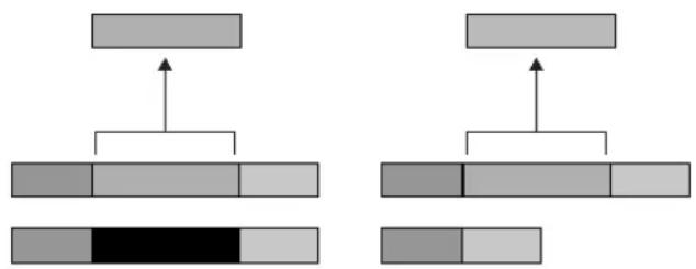
flowchart
graph TD
    A["Input"] --> B["Process 1"]
    B --> C["Output 1"]
    D["Input"] --> E["Process 2"]
    E --> F["Output 2"]
    G["Input"] --> H["Process 3"]
    H --> I["Output 3"]
    J["Black Bar"] --> K["Output 4"]
Comparison of Lift and Extract operations. Lifting material (left) leaves a gap that is replaced with black filler, and the length of the sequence remains the same. Extracting material (right) closes up the gap that the material previously occupied, and the sequence becomes shorter. In both cases, the material you remove is placed into the Clipboard.
The Copy to Clipboard function makes a duplicate of selected material in the sequence and leaves the material intact. When you copy material, the sequence remains unaffected. You can then insert the material elsewhere in the sequence or into another sequence.
To lift material:
- Mark In and Out points at the start and end of the material in the sequence that you want to lift.
- Select the tracks containing the material.
The system performs the function on selected tracks only. For more information on track selection, see “Understanding the Track Selector Panel” on page 707.
- Click the Lift button in the Edit tab of the Command palette to complete the edit.

To extract material:
- Mark In and Out points at the start and end of the material in the sequence that you want to extract.
- Select the tracks containing the material.
The system performs the function on selected tracks only. If sync locks are on, all material on all tracks is extracted. For more information, see “Understanding the Track Selector Panel” on page 707 and “Understanding Locking and Sync Locking” on page 714.

- Click the Extract button in the Edit tab of the Command palette to complete the edit.
To copy material to the Clipboard:
- Mark In and Out points at the start and end of the material in the sequence that you want to copy.
- Select the tracks containing the material.
The system performs the function on selected tracks only. For more information on track selection, see “Understanding the Track Selector Panel” on page 707.

- Click the Copy to Clipboard button.
The system copies the selected material to the Clipboard, and leaves the sequence untouched.
Using the Avid Clipboard
The Avid Clipboard is a cut, copy, and paste tool adapted to the special needs of the editing environment.
The Copy to Clipboard function is useful for moving or repeating material in a sequence without moving multiple segments or for rebuilding the section at another location. For example, you can:
- Copy a portion of a sequence for pasting into another sequence.
• Isolate and copy a portion of an audio track for looping music or repeating a sound effect. - Copy graphic elements for repeating at other locations in a format cut.
The Clipboard stores only one clip at a time. Each time you copy, lift, or extract additional material, you delete and replace the previous contents. However, you can preserve clipboard content for the duration of your working session when you add it as a clip to the Source monitor's Clip Name menu. All the clips added remain available in menu until you select Clear Menu or close the project.
The Clipboard lets you restore lifted or extracted segments quickly. This is useful if you have performed one or more edits since removing the material. In contrast, if you use the Undo function to restore the material, your Avid editing application also undoes all edits performed in the meantime.

Material in the Clipboard does not appear as a clip in the bin and is deleted when you close the project. To save a portion of a sequence for future use, mark the section and create a subclip.
To place a marked section of the sequence into the Clipboard at any time:
▶Click the Lift, Extract, or Copy to Clipboard buttons.
Left to right: Lift, Extract, and Copy to Clipboard buttons
To keep the Clipboard contents throughout a session, do one of the following:
Click the Clip Name menu above the Source monitor, and select Clipboard Contents.
The contents appear as a clip in the Source monitor, and the name “Clipboard Contents.n” appears above the monitor and in the Clip Name menu. The n is an incremental numbering of clips placed in the Clipboard during the session.
Press Alt key (Windows) or Option key (Macintosh) when you copy, lift, or extract the material. The contents appear as a clip in the Source monitor, and the name “Sequence name.Sub” appears above the monitor and in the Clip Name menu.
To restore material from the Clipboard:
- Load the Clipboard contents by doing one of the following:
Click the Clip Name menu above the Source monitor, and select Clipboard Contents to place the Clipboard contents into the Source monitor and add the clip name to the Clip Name menu.
Click the Clipboard Contents button in the Edit tab of the Command Palette.
▶ Open the Clipboard as a pop-up monitor by selecting Tools > Clipboard Monitor.


- Click the Mark Clip button to mark the entire segment.
- (Option) Click the Toggle Source/Record button in the Timeline toolbar to view, mark and select specific tracks.
- Locate the In point in the sequence from which the segment was removed. Move the position indicator here, or mark an In point.
- Splice or overwrite the material into the sequence.
Adding Comments to Sequence Clips
When you add comments to sequence clips, they appear in the Timeline or in lists that you create, such as an EDL or a cut list. Comments can include instructions for color correction or for adjusting an effect.
To add comments to the clips in a sequence:
- Click one of the Segment buttons (located in the Timeline palette), and highlight the clip to which you want to add a comment in the Timeline.

Segment Overwrite button (red) and the Segment Insert button (yellow)
- Click the Clip Name menu above the monitor, and select Add Comments.
The Comments dialog box opens.
- Type your comments in the text box, and click OK.
To display comments in the Timeline:
Click the Timeline Fast menu button, and select Clip Text.
Playing Back a Sequence
You can play a sequence at any time to see the results of your editing. You can view the sequence in the Record monitor or a Client monitor.
You can also play back your sequence in a continuous loop by augmenting the Play In to Out command with the Alt key (Windows) or Control key (Macintosh). You must set marks in the sequence to determine the range of the playback loop.

Use looping playback to isolate and continuously play back a small portion of a sequence during a difficult edit.
If you need to prepare a screening of the current cut or sequence away from the system, see the Avid FilmScribe Help for information on preparing a conformed cut or preview reel from workprint.

If you have several tracks of audio, you might need to mix them down and adjust levels before playback. For more information, see “Mixing Down Audio Tracks” on page 835.
To play a sequence:

- Click the Video Track Monitor icon located on the uppermost video track to display all video tracks and effects during playback.

- Click the Active/Inactive button to ensure proper playback of the audio tracks.
- Click the Data Track Monitor button to ensure proper playback of the data track.
You can only monitor and view the data on a client monitor capable of handling ancillary data. The hardware or client monitor needs to be able to decode ancillary data to playback your media. You can not playback from the Source or Record monitor.
- Go to the start of the sequence. Click the left side of the position bar to reposition the position indicator at the beginning or press the Home key on the keyboard.
- Use the position indicator, buttons, mouse, or keyboard to play, step, or shuttle through footage. View the sequence in the Record monitor or the Client monitor.
To start a playback loop:
- Mark In and Out points in the sequence. To play back the entire sequence, mark the In point at the beginning and the Out point at the end.
- Press and hold the Alt key (Windows) or Ctrl key (Macintosh) while you press the Play In to Out key, or click the Play In to Out button in the Play tab of the Command palette.
The playback loop begins and continues until you press the space bar or click anywhere with the mouse.


You can also press and hold the Alt key (Windows) or Ctrl key (Macintosh) while you click the Play to Out button. The location of the position indicator acts as the In point for a continuous loop.
Playback Performance Tips
As you edit, you might find the playback performance of your Avid editing application diminishing as the sequence grows in length and layers. This happens when you use a great deal of system memory for playback of large and complex sequences. The following are a few tips for improving playback performance:
- Check the number of media objects in use for your project in the Memory window (see “Using the Info Tab” on page 85). If this number is large, reduce the number of media objects by doing one of the following:
- Close bins that are not in use.
- Reduce the number of clips in the open bins.
- Unmount drives that are currently not in use.
See “Mounting and Unmounting Drives” on page 443. You can remount the drives at any time by selecting File > Mount All.
- When displaying real-time effects, adjust the video quality (see “Setting the Video Quality for Playback” on page 517).
- Restart your computer once a day to refresh the system memory.
- Split the sequence into two or more segments, if possible.
Playing a Limited Duration of a Sequence
Long sequences with many effects can be time-consuming to work with in the Timeline. Working with a shorter sequence can save time. The Play Length Toggle feature lets you switch between playing the entire sequence and playing a limited duration centered around the current position of the sequence. When you use the Play Length Toggle feature, the Play button and Play Length Toggle button change to white.
To play a limited duration of a sequence:

- Map the Play Length Toggle button from the Play tab of the Command palette to a monitor toolbar button.
For information about mapping buttons, see "Understanding Button Mapping" on page 110.
- Move the position indicator to the location where you want to start playing the sequence.
- Click the Play Length Toggle button.
The Play button and the Play Length Toggle button change to white, indicating the Play Length Toggle feature is active.
- Click the Play button.
The sequence plays for the default Play Length, which is 1 minute.
- To set the Play Length back to play the entire sequence, click the Play Length Toggle button again.
Understanding Sync Breaks
Sync breaks occur when a frame-accurate relationship between two clips or between the audio and video tracks within a single clip is offset during editing. Your Avid editing application provides several features to avoid, track, and remove sync breaks.
In many cases, sync breaks are the unavoidable result of selecting only one track in a synced relationship (for example, audio only or video only), and performing edit functions that change the duration of that track when you extract, splice-in, or add or remove frames.
By default, the Timeline displays sync breaks whenever they occur while you edit. They appear at break points as white numbers indicating negative or positive offset values relative to zero. The Sync Breaks option also displays match-frame edits as an equal sign (=) on the edits. For more information on match frames, see “Working with Add Edits (Match Frames)” on page 723.
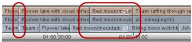
Match frames (left) and sync breaks (right) in the Timeline
You encounter sync breaks and match frames in different circumstances:
- You can encounter sync breaks in one or several video tracks, audio tracks, data track, or all. Sync-break offset numbers appear by default only in the affected tracks.
- You encounter match-frame cuts whenever you perform an add edit or whenever you move a segment next to footage from the same clip and the timecode is continuous across the edit.
You can customize the Timeline view to display sync breaks and match-frame edits in video tracks only, audio tracks only, or neither. For more information, see “Fixing Sync Breaks” on page 610.

The Sync Breaks feature applies only to master clips in which audio and video tracks were captured simultaneously, to autosynced subclips, or to any other subclip with video and audio tracks.
Tips for Avoiding Sync Breaks
One way to avoid breaking sync is to maintain the duration of the track when you add or remove material. The following table provides tips on how to do this in different circumstances:
| Task Tips | |
| Add material to a track | Use the Overwrite or Replace functions instead of Splice-in.For more information on overwrite and replace editing, see “Performing an Overwrite Edit” on page 585 and “Performing a Replace Edit” on page 586. |
| Remove material from a track | Use Lift instead of Extract. (The Lift function leaves filler of the same duration when you remove footage.)For more information, see “Lifting, Extracting, and Copying Material” on page 602. |
Task Tips
| Perform Segment edits | Use the Lift/Overwrite function instead of Extract/Splice-in. (Lift/Overwrite leaves filler behind and overwrites material at the new destination, maintaining sync in both cases.)For more information, see “Working with Segments” on page 693. |
Trimming Sync lock tracks to avoid breaking sync or use the Alt (Windows) or Option (Macintosh) key function for adding black during trims.
| For more information, see “Maintaining Sync While Trimming” on page 751. You can also perform dual-roller trims, which maintain duration, instead of single-roller trims. |
Tips for Fixing Sync Breaks
Working Mode Tips
| While trimming | Sync lock any additional tracks that are synced to the track you are trimming. Otherwise, you might restore sync in one track and break it in the others. For more information, see “Understanding Locking and Sync Locking” on page 714.Do not perform a dual-roller trim.Do not perform the trim on the Out point (A-side transition) of the out-of-sync segment. Always perform the trim on the In point (B-side transition) of the segment. |
| Source/Record mode | Do not use the Overwrite or Lift functions. You can, however, overwrite or lift the out-of-sync material entirely to eliminate the break.Splice in or extract selected frames of filler when necessary.Use the Add Edit function to isolate only a portion of a clip or filler segment in the sequence for extracting or replacing. |
| Segment mode | Use the Lift/Overwrite function to leave filler behind and maintain any other sync relationships affected by the move.Use the Lift/Overwrite function to delete the entire segment and leave filler to eliminate the break.Use the Add Edit function to isolate a portion of the clip for moving or deleting.Move the out-of-sync track, if possible, beyond the overlapping range with the synced material to eliminate the sync break. |
Fixing Sync Breaks
You fix sync breaks by eliminating the overlapping portion of out-of-sync tracks. You can do this in one of several ways, depending on the type of break and your sequence. For more information, see “Tips for Fixing Sync Breaks” on page 609.
You can customize the sync breaks display in the Timeline, for example to limit the display to video tracks only. This can reduce clutter and help you focus on a particular set of fixes.
To restore frames to sync while Trimming:
▶Perform one or more single-roller trims on the out-of-sync tracks.
Trim the exact number of sync-break frames displayed in the Timeline to reverse the break. For more information on performing trims, see “Working with Trim Edits” on page 732.
To fix sync in Source/Record mode:
▶ Add new material or extract material from the out-of-sync track.
Add or extract the exact number of offset frames displayed in the Timeline.
To fix sync when Segment editing:
▶Select and move the entire out-of-sync segment.
You can move the segment forward or backward in the opposite direction of the break to reverse it. For more information on editing segments, see “Working with Segments” on page 693.
To customize the Sync Breaks display:
▶ Click the Timeline Fast Menu button, and select Sync Breaks > option.
Understanding Sync Lock
The Sync Lock feature lets you maintain sync among several tracks while you add, move, trim, or remove material in a sequence. For example, if you insert an edit into one track that is sync locked to a second track, the system automatically inserts filler in the second track to maintain sync between the two.

Sync Lock icon (top) and Sync Lock All button (bottom) in the Track Selector Panel
There are several unique aspects to sync locking:
- You control sync lock by the Segment Drag Sync Locks option in the Edit tab of the Timeline Settings dialog and the Sync Lock icons in the Timeline. For more information on sync locking tracks, see “Maintaining Sync with Segment Edits” on page 700.
- When trimming, sync lock applies only to single-roller trims because dual-roller trims do not break sync. For more information on sync locking tracks when trimming, see “Maintaining Sync While Trimming” on page 751.
- You can sync lock any number of tracks in any combination. The tracks do not require matching timecode or common sources and can include multiple video tracks as well as audio tracks.
- Sync lock affects entire tracks. This means that parallel segments in other sync-locked tracks are affected when you add, move, trim, or remove material anywhere in the sequence.
Syncing with Tail Leader
You can add tail leader to the audio or video material to provide a useful visual reference in the Timeline for tracking and fixing sync breaks across any number of tracks.
Film editors traditionally use standard head and tail leaders for this purpose. You can create your own leader according to any specification, as described in “Creating Video and Audio Leaders” on page 622.
With tail leader added to synchronized tracks, you can go to the end of the sequence after you make a complicated edit and see if the leaders line up. If they are out of line, this indicates a sync break that you can eliminate.
To eliminate a sync break when the leaders do not line up:

- Move the position indicator to the black segment that follows the out-of-sync leader.
- Select the track, and then click the Mark Clip button. You can measure the break by checking the In to Out duration of the marked segment.
- Find the point at which the sync was lost.
- Use the appropriate edit function to add or remove frames, as described in “Fixing Sync Breaks” on page 610.
- (Option) For a quick fix, click the Segment insert (yellow arrow) button. Drag the black segment at the end of the out-of-sync tail leader to the location where the sync was lost. This segment of black, created when the track went out of sync, is the exact length of the sync break.

Syncing with Markers
You can add markers to material in the Timeline to track and adjust breaks in sync between any number of tracks. You can place markers anywhere in the sequence and you can add specific notes.
For more information on using markers, see "Using Markers" on page 523.
To mark sync points with markers:
- Move the position indicator to the point in the sequence where you want to maintain sync between two or more tracks.
- Select all tracks where you want the markers to appear.
- Click an Add Marker button.
The system adds a marker to the enabled tracks in the Timeline and in the Record monitor.


Example of markers in sync in the Timeline
To add a note whenever you park on the marker frame (such as Music sync or Sound Effect sync):
- Double-click the marker in the Source/Record monitor.
- Type your comments in the comment entry area of the Marker window.
The note appears in the Source/Record monitor.
To determine if sync is broken after an edit:
▶ Return to the segment that contains the markers and click the Focus button.
If the markers are not lined up, the sync is broken.
(Option) Use the Find procedure to go to a marker quickly with text. For more information, see “Finding Frames, Clips, and Bins” on page 538.
To adjust the sync break:
- Measure the sync break:
a. Move the position indicator to the leftmost marker and click the Mark In button. b. Move the position indicator to the other markers, and click the Mark Out button.
- Check the In to Out duration of the marked section.
To restore sync:
- Find the point at which the sync was lost.
- Use the appropriate edit function to add or remove frames, as described in “Fixing Sync Breaks” on page 610.
Using Add Edit When Trimming
When you trim with several audio tracks in sync, you can create an edit in the silent or black areas of the synced tracks. They occur in line with the track you trim, and they trim all the tracks at once to maintain sync.

You can also add an edit to filler. For more information, see “Working with Add Edits (Match Frames)” on page 723.
To use the Add Edit button while trimming:
- Move the position indicator to the edit that you want to trim.
- Select only the additional tracks that are in sync, and click the Add Edit button.
The system adds a transition at the location of your position indicator in the Timeline.
- Select the transition and trim (be sure to select all the synced tracks).
As you trim, the system adds or removes frames from the additional tracks.
- When you finish trimming, select Clip > Remove Match Frame Edits to remove the add edits from the sync tracks.
Ganging Footage in Monitors
The Gang function does not combine tracks into a synced relationship but locks monitors in sync so that you can move through footage in two or more monitors simultaneously. This function is convenient when you view and mark the sequence and source material simultaneously, based on syncing of the position indicators in each monitor.
You can gang the Source monitor and any number of pop-up monitors with the Record monitor. For instance, before you edit them into a sequence, you can gang a music track in a pop-up monitor, source footage in the Source monitor, and a sequence in the Record monitor. Then you can view the footage, adjust the sync points, and mark them before you complete the edit.

The Gang button appears by default in the second row of buttons below the Source and Record monitors.
To gang footage in monitors:
- Load a sequence into the Record monitor.
- Load one or more clips into the Source monitor and pop-up monitors.
- Click the Gang button for each monitor that you want to synchronize (the Record monitor is always ganged).
- View the footage in any of the monitors.
As you move through footage in one monitor, the footage in all other monitors freezes. The footage is updated when the play stops. Simultaneous full-motion playback is not possible, although the system maintains sync at all times.
Sync Point Editing
Sync Point editing lets you overwrite material onto your sequence so that a particular point in the source material is in sync with a particular point in the sequence. For example, you can sync an action in the source video with an audio event, such as a musical beat in the Record monitor, and then edit it so that the action occurs on the beat.
Like a replace edit, Sync Point editing uses the relative location of the position indicator in both the source and record material as the sync point. Sync Point editing, however, determines the duration of the new edit according to marks that you set, as opposed to a replace edit, which uses the head-to-tail frame duration already established in the Timeline. You can apply these marks across multiple tracks when you mark a sequence. This lets you add overlap cuts.
Sync Point editing requires two pieces of information:
- Sync points: The points where the synchronized relationship between the source and record material is established.
- Duration of the relationship: This is determined by the positions of the head and tail frames (and sometimes by the position indicator). Both marks are in one monitor, or one mark is in one monitor and the other mark is in the other monitor. The duration of the material being edited into the sequence is sufficient for the size of the edit.
To perform a sync point edit:
- Load a clip or sequence into the Source monitor.
- Load a sequence into the Record monitor.
- Mark the material in one of the following ways:
Mark the In and Out points in either the Source or Record monitor, leaving the opposite monitor clear of marks.

Mark an In or Out point in the Source monitor, or an In or Out point in the Record monitor. For example, if you marked an In point in the Source monitor, mark the Out point in the Record monitor.
- Move the source position indicator to the sync frame in the clip.
This establishes the source sync point.
-
Move the record position indicator to the sync frame in the sequence.
-
Select Sync Point Editing (Overwrites) in the Edit tab of the Composer Settings dialog box or select Special > Sync Point Editing.
The orange mark on the Overwrite button signals Sync Point editing is active.
- Select the source and record tracks for this edit, then click the Overwrite button. The system completes the sync point edit.

Autosyncing Clips
When you capture footage that includes both audio and video, your Avid editing application automatically establishes sync when it creates clips in the bin. Autosyncing applies to audio and video clips that you capture separately, usually from two separate sources. Autosyncing creates a new subclip that displays sync breaks in the Timeline as though the audio and video were captured simultaneously.
| lections | Team rafting | Fla3 | Bed1 |
| lections | Team rafting | Fla over lak | |
| lections | Team rafting | Fla over lak | |
| 1:00:15:00 | 64:00:30:0 | ||
Example of sync break information in the Timeline

For more information on tracking sync breaks, see "Fixing Sync Breaks" on page 610.
Understanding Autosyncing
Autosyncing is often used for projects in which picture and sound were captured separately. These clips are often synced based on common film timecode, sound timecode, or auxiliary timecode.
You can also autosync ^™ any audio and video clips based on a user-defined In point or Out point relationship that you establish with marks. For example, you can use the slate as a common visual and audio reference for autosyncing the clips.
Use the following guidelines when autosyncing:
- You can autosync audio clips with video clips only. To link two or more video clips or audio clips, use the Grouping option described in “Understanding Grouping and Multigrouping Clips” on page 1292.
- You can create only one autosynced subclip at a time. You cannot autosync numerous pairs of audio and video clips simultaneously.
- If the audio and video clips do not have matching source or auxiliary timecode, you must establish common sync frames. To do this, mark In points (or Out points) on both clips before you autosync. When you autosync using this method, the whole clip is taken into the subclip.
- If you autosync clips of different lengths, the longer clip is truncated to the length of the shorter clip; video clips override audio clips.
- If you autosync according to common timecodes that are staggered (one clip starts later than the other), the later starting timecode becomes the start of the new subclip. The clip with the earlier starting timecode is trimmed accordingly.
Creating an Autosynced Subclip
To create an autosynced subclip:
- Highlight two or more clips in the bin.
- Select Bin > AutoSync.
The Sync Selection dialog box opens. - Select an option, based on the following:
Option Description
Film TC/Sound TC Use this option if you sync clips with matching film and sound timecode recorded in the field. This option appears dimmed if you are not in a 24p or 25p project.
Inpoints Use this option if you sync two clips at a time according to In points set in both clips.
Outpoints Use this option if you sync two clips at a time according to Out points set in both clips.
Source Timecode Use this option if the two clips have matching timecode or to Autosync multiple clips, use the Start timecode. The default option.
Option Description
| Auxiliary TC1–TC5 Use this option if the two clips have matching timecode in the same Auxiliary Timecode column or to Autosync multiple clips, use the Aux 1-5 timecode. Select an Aux TC, 1 through 5, from the menu. | |
| Keep audio on clip with video | Use this option if you want to keep the selected video clip's audio tracks. Specify which audio tracks you want to keep from the Start and End range. All audio tracks within this range will be kept. Off by default. |
| Include audio from audio-only clips | Use this option to keep the selected audio tracks with the audio-only clip. Specify which audio tracks you want to keep from the Start and End range. All audio tracks within this range will be kept. Off by default. |
| Collapse Audio Tracks | Use this option to remove any unused audio tracks and then move the audio tracks to the next available tracks. For example, if you have 8 audio tracks but tracks A2, A4, A6 and A8 did not have audio. If you select this option, tracks A2, A4, A6 and A8 would be removed and A1, A3, A5 and A7 would move into the A1 through A4 tracks. Off by default. |
4. Click OK.
The subclip is created and named by default after the video clip with the file name extension .sync.n, where n is the incremental number of subclips created with the same name.
You can change the name according to preference. You can load an autosynced subclip into the Source monitor and immediately edit it into a sequence.

In a 35mm 4 perf or 35mm 3 perf project type, you can "perf slipped" the subclip up to a 1/4 frame in either direction for even tighter sync.
Understanding AutoSequence
AutoSequence is used when picture and sound are captured separately. AutoSequence lets you add audio or video to the original videotape if it was transferred without sound or picture. You can also use the AutoSequence feature to organize dailies without having to duplicate source clips when you move them to other bins.

For information and procedures for Autosync, see “Autosyncing Clips” on page 615.
To establish sync with the original videotape, use filler to add where gaps in audio or video exist in the sequence. After you finish editing the audio or video, you can use the Digital Cut command to output only the audio, or both audio and video only the video onto the original videotape.
If you do not use AutoSync and the video clip timecode does not match the audio clip timecode, you should select only video clips when you use AutoSequence. You can then add audio to the sequence and sync the audio with the video by using the Splice-in and Overwrite functions.
You can use the AutoSequence command with imported or AMA linked clips. You can also AutoSequence multiple clips together with non-continuous timecode, closing the gap on the filler in your sequence. This is helpful if you want to create a rough cut sequence with imported or linked clips.
Use the following guidelines when you create a synchronized sequence:
- Your original videotape must have continuous timecode.
- Use only master clips, subclips, autosynced subclips, and/or group clips to create the synchronized sequence.
- If you select two unrelated clips with overlapping timecodes, a message box indicates you cannot do this operation. If the clips are related (for example, one clip is a subclip of the other master clip), then one of the clips is selected automatically.
- The system removes and ignores points in the clips. A message box provides you with a choice to continue and remove the points or to cancel the operation.
- Synchronized sequences are named from the Tape Name column for tape-based media and the Source File column for file-based media.
Adding Audio or Video to Original Videotape Using AutoSequence

If you add audio only, make sure the video tracks are not enabled when you begin recording a digital cut. If you add video only, make sure you do not enable audio tracks when you record a digital cut.
To add audio or video to your original videotape:
- (Option) Use the AutoSync command to create synchronized subclips from your tape's master clips and your audio or video clips.
- Open the bins that contain the clips you want to include in the sequence.
- Select the clips.
- Select Bin > AutoSequence.
The system creates a synchronized sequence with the clips you selected. The new sequence appears in the Record monitor and in the Timeline. The sequence also appears in the bin with the same name as the tape name (for tape-based media) or the same name as the source file name (for file-based media) with a .xx (.01, .02, .03) extension.
- Edit the audio or video tracks.
- Record a digital cut of the audio or video directly onto the original videotape when you finish editing the sequence.
- (Option) Press and hold the Alt (Windows) or Option key (Macintosh) while you select Bin > AutoSequence to build a sequence without filler.
The system creates a sequence without gaps by placing the clips in ascending timecode order.
Resyncing Subframe Audio
When you work with a 24p or 25p project (35mm, 4-perf or 35mm, 3-perf only), you can adjust the sync between the audio and video portions of subclips at the subframe or perforation level (1/4-frame adjustments for 4-perf and 1/3-frame adjustment for 3-perf) for more exact sync.
When you perform a subframe resync, you can obtain a closer relationship between audio samples and film frames than the relationship established in the film-to-tape transfer process. For example, when a film lab punches the correct clapsticks frame to match the audio clap, during telecine transfer, the process of aligning the sync points is inexact. As a result, true sync might be off by one or more perforations.
The following conditions apply to resyncing at the perforation level:
- You can adjust the sync between a single video and a single audio track within subclips only. Use the subclips created:
- When you autosync
- Manually from master clips in preparation for editing
- From an imported shot log
- While you capture
- From imported audio media (OMFI, AIFF-C, or WAVE format), master clips generated by AudioSuite plug-ins, or tone generator media
- You cannot slip at the perforation level of the imported QuickTime audio media.

The batch import process does not create new clips; therefore, slipping at the perforation level is not available when you batch import audio clips from Symphony versions earlier than v3.5.3 and Avid editing application versions earlier than v10.5.3.
- You cannot slip beyond the duration boundaries of the source master clip.
- The sync adjustments you make are referenced in any cut list you output for any sequence that uses the adjusted subclip.
- The number of perfs you slip appears in the Slip column when you select the Slip heading to display in the bin.
Resyncing Audio for a Selected Subclip
To resync audio for a selected subclip:
- Load the subclip into the Source monitor.
- Use one of the audio scrub techniques described in "Using Audio Scrub" on page 768 to locate the closing slate frame.
- Click Slip Left One Perf or Slip Right One Perf button to move the audio sync either backward or forward in 1-perf increments.
Each click of the perf button performs the sync adjustment.
- Play the subclip in the Source monitor to evaluate your sync adjustment. Repeat the previous steps to further adjust the sync, up to eight perfs in either direction.
- Use the resynced clip to edit into the sequence.

If you find a subclip frame sync problem within an edited sequence, be sure to correct the audio sync in the original subclip used in the edit. The sequence is then updated. The telecine facility must correct sync problems with 16mm format.
Working with Phantom Marks
Phantom marks provide visual guidance when you edit according to the three-mark rules. For information on editing using three marks, see “Editing Additional Clips into the Sequence” on page 584.
To enable phantom marks:
- In the Settings tab of the Project window, double-click Composer.
The Composer Settings dialog box opens.
- In the Edit tab, select Phantom Marks., and then click OK.
When you enable phantom marks, your Avid editing application displays blue mark In or Out icons in the position bars below both the Source and the Record monitors. These phantom marks indicate one, two, or sometimes three edit points calculated by your Avid editing application to complete an edit.
The following examples illustrate two typical scenarios.
Setting One Mark
In this example, you set only the mark In on the source side. By default, your Avid editing application uses the location of the position indicator as the mark In for the sequence and calculates both Out points based on the length of the source clip.

One mark IN set (left) and three phantom marks (right)
You can see your Avid editing application calculations instantly and can make the edit after you set just one mark.
Adding a Second Mark
If you decide that a mark Out is required — to shorten the source clip, for example — then your Avid editing application recalculates and displays new phantom marks.

Phantom marks can help you see the results of marks you set before you complete the edit and are useful when you perform a Sync Point edit or other complicated replace edits in which two or more marks calculate automatically.
Creating Video and Audio Leaders
Film editors use standard head and tail leaders to cue and sync material. You can use digital leaders in your Avid editing application to mark the beginning and end of tracks and to help you maintain sync, as described in “Syncing with Tail Leader” on page 611. You can create your own leader for video or film. Whatever you choose for specifications, make all your leader clips the same length, with common sync points.
To create leaders for picture tracks:
- Create a black screen in the Title tool for tail leader, or a white screen for head leader. For information on using the Title tool, see “Creating Titles” in the Help.
- (Option) Type a title onto the screen that says Tail Leader or Head Leader.
- Name this clip Head Leader or Tail Leader when you save the title.
- Create a subclip from an appropriate length of the clip, according to your chosen specifications.
- (Option) Mark a sync frame in the subclip as follows:
a. Load the clip into the Source monitor.
b. Find an appropriate sync point, and add a marker.
For more information, see “Using Markers” on page 523.
c. (Option) Double-click the marker in the Source monitor to add a sync point notation that appears on the monitor.
Once you prepare the leader, you can splice the leader while you edit onto the tracks that you want to keep in sync. You can use the sync points for visually aligning tracks.
To create tail leader for audio tracks:
- Load a clip that includes a section of captured tone into the Source monitor.
- Create a subclip according to your chosen specifications.
- Name this new subclip Head Leader or Tail Leader.
- Load this subclip into the Source monitor.
- To prepare the sound levels for leader without a sync point (no audio pop), open the Audio Mixer tool and bring the audio level all the way down for the entire clip.
- Prepare the sound levels for leader that include a sync point (audio pop) by doing the following:
a. Find the appropriate sync point.
Step one frame backward and place an add edit before the sync frame; then step two frames forward and place an add edit after the sync frame.
For information on placing add edits, see “Working with Add Edits (Match Frames)” on page 723.
b. Move the position indicator before the first add edit, and open the Audio Mixer tool.
c. Bring the audio level all the way down.
d. Move the position indicator after the second add edit, and use the Audio Mixer tool to bring the level all the way down.
After you prepare the leader, you can splice the leader while you edit onto the audio tracks that you want to keep in sync. You can use the sync points for visually aligning tracks.
Script-Based Editing
The following topics provide information about working with script-based editing:
• Understanding Lined Scripts
- Script Integration — Lining in the Digital Realm
• Understanding the Script Window
• Working with the Script Window
• Working with Script Text
• Working with Page or Scene Numbers and Searching in a Script
- Linking Clips to a Script
• Interpolating Position for Script Integration
- Working with Slates in the Script Window
- Working with Takes in the Script Window
- Indicating Off-Screen Dialog in a Script
• Using Color Indicators in the Script Window
- Script Marks
• Finding Clips and Script
• Editing From the Script Window
Understanding Lined Scripts
The conventional lined script evolved during decades of trial and error in Hollywood. It provides assistant editors and chief editors with a road map that helps them find the coverage they need to edit scenes in a film or television show.
The script-based editing feature in your Avid editing application lets you adapt the lined script to the digital realm for use in any type of production, from drama to documentary to spot advertising. For more information, see “Script Integration — Lining in the Digital Realm” on page 626.
A traditional lined script is created by hand at the time of shooting. The following is an example of a scene from a lined script.
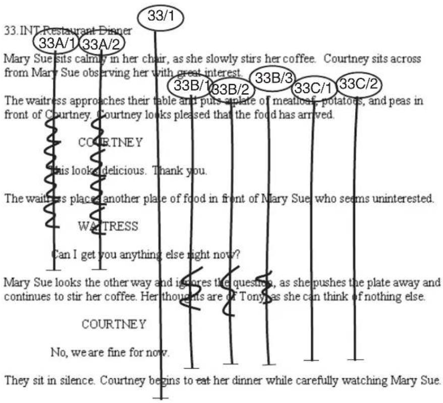
Each vertical line drawn through the scene represents a single take from the moment the director says “Action” to the moment the director says “Cut.” Each scene might require several camera angles and positions, with one or more takes, all of which are lined and identified alphanumerically.
The following table summarizes the lining techniques and numbering system shown in the example.
| Master shot | The line labeled 33/1 is the master shot that usually covers all the action in a wide shot. The first number in the label indicates the scene number as written on the script (scene 33). The number following the slash indicates that this is the first take captured on film for the master shot. A second take of the master shot, for example, would be labeled 33/2. |
| Additional setups | The lines for each subsequent camera setup within the scene are labeled with the scene number (33 in our example) followed by a letter for each setup, followed by a slash and the number of the take within that setup. These lines can be any length, depending upon what portion of the script is covered by the particular shot. |
| Off-screen dialog | The jagged lines in the script represent the parts of dialog where the actor is off screen. For example, the character Mary Sue is off camera during the action described in the second paragraph (when the waitress character enters), so a jagged line is drawn through the shots that cover Mary Sue (33A/1 and 2). |
When the scene is recorded — for example, in a sitcom shoot — the lined script can also include timecode notes written next to specific lines of dialog that represent a sync point between the dialog on the page and the recorded dialog. These sync points provide assistant editors or chief editors with a quick path to specific points in the source material.
Script Integration — Lining in the Digital Realm
Script integration in your Avid editing application enhances the traditional lined script system described in “Understanding Lined Scripts” on page 624.
Unlike the traditional lining of a script, digital script integration usually happens after the shoot. For example, the assistant editor uses the notes of the continuity person as the basis for script integration. The following is an example of the script shown in “Understanding Lined Scripts” on page 624, prepared and lined using script integration.

1 Toolbar 5 Off-screen indicator
2 Slates 6 Color indicator
3 Takes tabs 7 Script mark
4 Takes
In addition to the standard lining conventions, script integration includes the following enhancements:
Slates Takes are organized into slates that display a representative frame and clip name for the take that is currently selected.
Takes The Takes tabs and lines extending from the bottom of each slate indicate the number of takes for that scene. Click a Takes tab to select the take.
Indicators You can apply off-screen dialog indicators or colors to indicate such things as preferred takes, takes used in the current active sequence, or line changes in dialog.
Script marks The double arrows marking the takes at various points represent marked lines of dialog in the script that are synchronized to matching dialog in the source clip. Script marks are especially effective during editing, allowing the editor to quickly locate dialog and piece together parts of a scene.
The Script window provides additional controls for matching back to clips in the source bins, loading and playing back takes, and searching for takes and script text.
Script Integration Workflow
The basic workflow for script integration is as follows:
- The continuity person or an assistant creates the lined script in hardcopy form during shooting.
- Source footage from the shoot is prepared and captured by using methods described in "Creating a New Project" on page 50.
- The assistant editor uses the lined script from the shoot, a text file of the script itself, and methods described throughout this chapter to import and line the script, link clips to the script, place script marks, and customize the display of takes prior to editing. In some Avid editing applications, the assistant can also use the ScriptSync ^™ feature to automatically place script marks.
- The editor uses the fully prepared Script window to edit the program.
Using Script Integration in Video Projects
Script integration is an effective tool for editing any type of production, not just feature films and television drama. For example:
- You can adapt many of the procedures described in this chapter for use in audiovisual scripts for documentaries, corporate spots, news magazine segments, and spot advertisements.
- You can turn script integration into a quick storyboarding tool by positioning selected slates in the Script window and printing storyboard bins that include your script.
The following is an example of an audiovisual script for a news magazine piece imported into the Script window, with the basic features of script integration applied.

flowchart
graph TD
    A["Narration"] -->|2| B["Starting"]
    B --> C["Rafting"]
    C --> D["Music for"]
    D -->|2| E["Music for"]
    E --> F["Biking"]
    F --> G["Oversolve to: MOUNTAGE OF ATHLETES"]
    style A fill:#4CAF50,stroke:#333
    style B fill:#4CAF50,stroke:#333
    style C fill:#4CAF50,stroke:#333
    style D fill:#4CAF50,stroke:#333
    style E fill:#4CAF50,stroke:#333
    style F fill:#4CAF50,stroke:#333
    style G fill:#4CAF50,stroke:#333
Left to right: narration track synced to the script, B-roll shots ready to be loaded and cued (color indicates preferred shots), music cuts linked to appropriate sections of the script.
Understanding the Script Window
You begin the script integration process by importing a script into a project. The script appears in a script bin, and opens in a Script window.
Script Settings
You use settings in the Script Settings dialog box to control how scripts display in the Script window and how the Script window behaves. You should make changes to these settings before you open a Script window. After the Script window is open, any changes you make in the Script Settings dialog box are ignored by the window. You must close the Script window and then reopen it for the new settings to take effect.
However, the Script menu provides several commands that override the Script settings. Script menu commands are described throughout this chapter.
You can also specify the text encoding of the script from the Script menu. This ensures that diacritical marks and multibyte character sets appear correctly in your script.
Script Window Behavior
The Script window behaves in many respects like a bin:
- When you make changes in the Script window, an asterisk appears in the title bar to indicate that the changes are not yet saved.
- The Script window has the same auto-save functionality as bins, based on the auto-save options in the Bin settings.
- Your Avid editing application saves Script window files in the project folder along with bins, and stores backup copies automatically in the Avid Attic folder.
When you save a Script window, the saved file has an .avc file name extension.
You can navigate to any point in the text of a script by using basic techniques available in most word processors. You can also use several search features, as described in “Working with Page or Scene Numbers and Searching in a Script” on page 635.
You can resize a Script window at any time to show more script or to enlarge the right margin. The default size of the left margin is established on import, based on the current Script settings, but you can override the margin setting and adjust the left margin after importing the script.
You can open the Info window, which displays statistical information about a clip or sequence, directly from the Script window. The window updates the information automatically.
For details of basic Script window procedures, see “Working with the Script Window” on page 630.
Working with the Script Window
This topic describes basic procedures for working with Script windows, including importing script text, navigating through the script, displaying clip information, opening and closing windows, saving windows, and adjusting margins. For more information on the Script window, see “Understanding the Script Window” on page 628.
Before you begin creating Script windows, make sure you have established the proper defaults in the Script Settings dialog box for font, margin, and display of frames and takes.
To set Script settings:
- Double-click Script in the Settings list in the Project window.
The Script Settings dialog box opens.
- Make the changes to settings that you need, and then click OK.
For information on the settings, see “Script Settings” on page 1435.
To import a new script:
- Place the script file in a local or network directory that is available to your Avid editing system.

The imported script must be in text format. To maintain the original formatting, however, export the script from your word processor by using the “Text Only with Line Breaks” option. If you export the script as “text” only, the formatting is lost.
- Click the Bins tab in the Project window of your Avid editing application.
The Bins list appears.
- Select File > New Script.
The Open dialog box opens.
- Select the file, and then click Open.
A script bin appears in the Bins list in the Project window. The script, with its original layout, appears in the Script window.
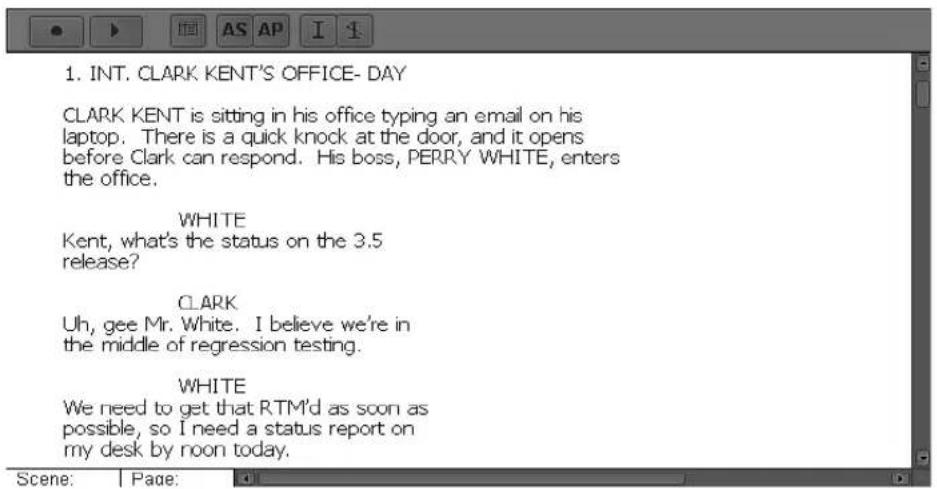
- Change the name of the script bin by clicking the title in the Bins list in the Project window, and typing a new name.
To select text encoding:
▶Select Script > Text Encoding, and then select one of the following:
| Option Description | |
| None Your Avid editing application uses your system’s default encoding.Select this option when the text was created on a system with the same system character set you are currently using. Use this option for non-Latin-based encoding where UTF-8 was not used. | |
| Mac(MacRoman) | Select this option when the script was created on a Macintosh system using the MacRoman character set. This is the default encoding on Macintosh systems for plain text using the Latin character set. |
| PC (Latin-1) | Select this option when the script was created on a Windows-based system using the Latin-1 character set. This is the default encoding on Windows-based systems for plain text using the Latin character set. |
| UTF-8 Select this option when the script was created using the Unicode UTF-8 character set. | |
| Non-native characters might not display correctly even if they are encoded in UTF-8. The ability to display non-native characters is limited at this time. | |
To open, close, or save the Script window:
To open a new script (.txt) file and add it to the Bins list in the Project window, select File > New Script.
To open existing Script window (.ave) files and add them to the Other Bins folder in the Bins list in the Project window, select File > Open Bin.
▶To close Script windows, select File > Close.
▶To save changes, select File > Save Script.
▶To save a copy of the Script window, select File > Save a Script Copy As.
To explore the Script window:
▶Use the bar on the right to scroll up or down.
▶ Resize the window by dragging the size box in the lower right corner.
▶Press the Page Down or Page Up key to move one screen at a time.
▶ Press the Home or End key to move to the beginning or end of the script.
▶ Press the Up Arrow or Down Arrow key to move your line selection up or down by one line.
To adjust the left margin of an imported script:
- Select Script > Left Margin.
The Left Margin dialog box opens.
- Type a new margin size (in pixels) in the text box, and click OK.
The Script window reflects the new setting.
To open the Info window from a Script window:
- Press the Alt key (Windows) or the Option key (Macintosh), and click the Takes tab.
- Drag the window to a new location to leave the Info window open.
Working with Script Text
The default font and font size for a script is established when you import the script, based on the current Script settings. You can override the settings and change the font and size after importing the script.
You can also cut, copy, paste, or remove selected lines of script to reflect changes that might occur during the course of a project. Selecting text in the Script window is similar to making selections in a word processor, except that the smallest unit you can select is an entire line of text. You cannot select or otherwise manipulate individual characters or words.

To rearrange or rewrite individual words or characters in a script, make the changes in a word processor, import them into a separate Script window, and then use the procedures in this topic to copy and paste the new lines into the existing Script window, overwriting the incorrect lines.

You cannot undo cut, copy, or paste operations in the Script window.
To change the font and font size of imported script:
- Select Edit > Set Font.
The Set Font dialog box opens.
- Click the Font menu, and select a new font.
The menu includes all fonts currently installed on your system.
- Type a new font size in the text box, and click OK.
The Script window reflects the new settings.

As you enlarge font size, the available sizes for the slate frames also increase. This is useful for presentation or screening purposes, when you need to display extra-large text and slate frames for a large audience or across a room. For information on enlarging slate frames, see “Working with Slates in the Script Window” on page 639.
To select a single line of script:
▶Click anywhere in the line to highlight it.
To select several lines of script, use one of the following methods:
Lasso the first line of the selection, drag through the text, and release the mouse button when you finish lassoing the lines you want to select.
As you drag, a box outlines your selection. After you release the mouse button, the text is highlighted.
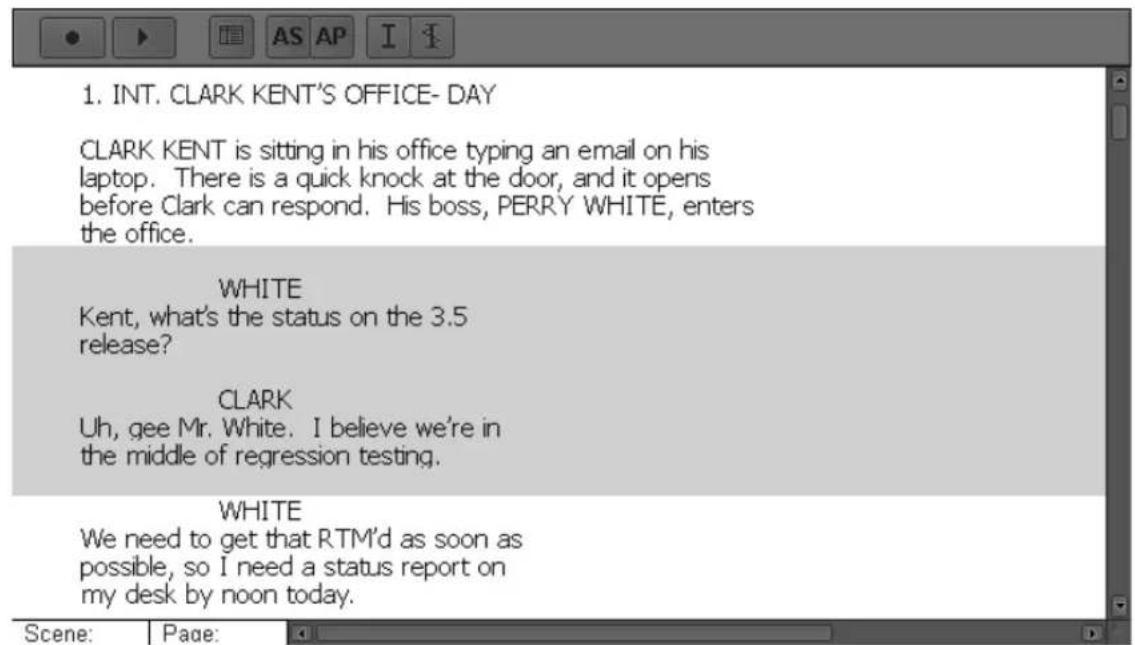
Example of a lasso to select a portion of a script
▶ Click the first line of the selection, and then Shift+click the last line. The entire block of text is highlighted.
▶ Press Ctrl+A (Windows) or Command+A (Macintosh) to select all the text and takes.
To extend an existing selection:
▶Shift+click a line of text preceding or following the existing selection.
To cut or copy lines of script and then paste them:
- Select the lines.
- Select Edit > Cut or Edit > Copy.
- Select the line below the location where you want to insert the text.
- Select Edit > Paste.
If you select only one line at the insertion point, a message box asks if you want to replace the selected line.
If you select more than one line at the insertion point, no message box opens. When you select Edit > Paste, your Avid editing application replaces the selected lines with the text you cut or copied in step 2. You cannot use the Undo command after performing this step.
- Do one of the following:
▶Click Replace to overwrite the selected line.
▶Click Insert Before to insert the text above the selected line.
▶Click Insert After to insert the text below the selected line.
The text is pasted into the script.
To remove lines of script:
- Select the lines of script you want to delete.
- Select Edit > Cut.
Unlike a normal deletion, the text remains in the Windows Clipboard or Macintosh Clipboard until the next time you copy or cut a selection.

You cannot delete lines of text from the Script window by using the Delete key as you would in a normal word processor. Use the Cut command to remove the text.
Working with Page or Scene Numbers and Searching in a Script
Script integration provides a number of search tools you can use during the preparation phase, during editing, or during screenings. You can use page or scene numbers, or you can conduct a full-text search.
When you add page and scene numbers to the Script window, you gain the ability to search for them during preparation of the script and during editing. You can change a scene or page number to correct any errors that occur when adding numbers, and to reposition scene and page numbering to match script changes during postproduction.

You can use the Find Bin and Find Script buttons to match back and forth between script and clips. For more information, see “Finding Clips and Script” on page 663.
To add a page or scene number:
- Select the line of the script at the beginning of the scene or page.
- Click the Add Scene (AS) or the Add Page (AP) button in the Script window toolbar, or select Script > Add Scene or Script > Add Page.

A dialog box opens.
- Type the number for the scene or page, and click OK.
The scene number appears in the left margin. The page number appears in the right margin next to the first line of the selected region. Scene and page numbers both appear in the status bar at the bottom of the Script window and reflect your current position within the script. Each scene or page number continues throughout the script until you mark another line as the beginning of a new scene or page.
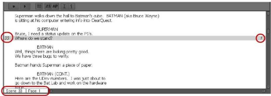
Top left: new scene number. Top right: new page number. Bottom: Scene and page number indicators in the status bar.
To change a page or scene number:
- Select the beginning line of the scene or page.
- Do one of the following:
▶Click the Add Scene or the Add Page button in the Script window toolbar.
▶Select Script > Add Scene or Script > Add Page.
A dialog box opens.
- Type a new number for the scene or page, and click OK.
- If the renumbering affects page or scene numbers that precede or follow the current change, then repeat these steps as necessary.
To delete a page or scene number:
- Select the first line of the scene or page.
You can also delete all page or scene numbering throughout a range of the script by selecting the range of lines or the entire script.
- Press the Delete key.
The Delete dialog box opens.
- Select the options for Delete scene(s) or Delete page break(s) as appropriate, and click OK.
Your Avid editing application deletes the numbering from the Script window.
To search for a page or scene number:
- Select Script > Go To Page or Script > Go To Scene.
You can also click in the page or scene display in the status bar at the bottom of the Script window.
The Go To Scene/Page dialog box opens.
- Type the number of the scene or page, and click OK.
The Script window scrolls to the page or scene, and the first line is highlighted. If you type a page or scene number that is not in the script, then no action occurs.
To search for text in a script:
- With the Script window active, select Edit > Find.
The Find dialog box opens.
- Type the text you are looking for.
- Select one of the optional search parameters, when appropriate:
▶If you do not want the search to be case sensitive, select Ignore Case.
If you do not want the search to highlight instances where your text is part of another word, select Whole Word.
- Click OK.
The first occurrence of the text is highlighted in the Script window. - Select Edit > Find Again to search for the next occurrence of the text.
Linking Clips to a Script
You can link clips to the script by hand, or, if your Avid editing application includes the ScriptSync feature, you can use ScriptSync to automatically link clips to the script. For more information about ScriptSync, see “Marking with ScriptSync” on page 650.
To link clips to the script:

- Open the script bin by double-clicking the Script Bin icon.
- Open the source bin for the clips that you want to link to the script.
- (Option) Sort the source clips to make the job easier:
You can sort the Scene/Take column for an alphanumeric list of clips that matches their relative order in the script.
If you are not working with scene and take information (for example, in a video documentary project), you can provide your own numbering for the clips in a custom column, or you can sort the clips manually in Frame view according to their order in the script. For more information on adding a custom column, see “Adding Customized Columns to a Bin” on page 347.
- Select the portion of the script that is covered by the first clip or clips.
- Select the clip or clips in the source bin, and drag them to the highlighted text.
Make sure the pointer is over the highlighted text before releasing the mouse button.

Drag one or more clips to the highlighted material in the Script window
A slate frame appears above the text, with one or more of the takes covering the scene as lines.

- Continue to apply clips to additional portions of the script until you have finished creating all your slates.
Alternatively, you can create slates one at a time, place script marks, and fine-tune the lining of each scene before proceeding to the next portion of the script.
Interpolating Position for Script Integration
Interpolate Position matches a clip to a take and lets you see where a particular line in the script would appear in the clip footage.
When you set Interpolate Position, your Avid editing application matches the length of the take in the script to the length of the clip in the Source monitor. The position indicator in the Source monitor corresponds to wherever you double-click in the take.
If you set a script mark in the take, the portions of the take on either side of the script mark are matched to the portions of the clip on either side of the IN point in the Source monitor.

You can change the default behavior before opening a script in the Script window by selecting Interpolate Position in the Script Settings dialog box. See “Script Settings” on page 629.
To set Interpolate Position:
▶Select Script > Interpolate Position.
Working with Slates in the Script Window
Once you create a slate by dragging a clip into the Script window, you can manipulate the slate's appearance and position. You can:
- Select one or more slates.
Selecting multiple slates is especially useful when you are adding or deleting color or off-screen dialog indicators across takes, as described in “Working with Takes in the Script Window” on page 642.
- Resize slates in the same way that you resize frames in the bin in Frame view.
You can also enlarge the font size of the script to increase the size of the slate frames. This can be useful for presentation or screening purposes when you need a large display for an audience. For information on resizing the font, see “Working with Script Text” on page 632.
- Hold slates on screen so that, as you scroll a script in the Script window, each slate remains on screen as long as the take lines to which it is linked remain on screen.
- Hide the representative frame that your Avid editing application displays by default for each slate.
When you do this, your Avid editing application shows only the clip name to simplify the interface or speed up scrolling and movement in a complex Script window.
• Show only one take for each nonactive slate to minimize screen clutter.
- Adjust the position of slates to make room for more slates, to avoid blocking words, or to display takes over specific lines.
- Delete slates, for example, if you find that you no longer need the takes in the slate.
To select slates, do one of the following:
▶Click a slate to select it.
▶Shift+click additional slates to select all the active takes.
▶Drag a lasso through a region of the script containing slates.
All slates and takes within the lasso are selected.
To enlarge or reduce the slates:
▶Select Edit >Enlarge Frame or Edit >Reduce Frame.
To hold slates on screen, do one of the following:
▶ Select Hold Slates Onscreen in the Script Settings dialog box before you open the Script window.
For more information, see "Script Settings" on page 629.
▶Select Script > Hold Slates Onscreen.
To hide or show the slate frames, do one of the following:
▶ Select or deselect Show Frames in the Script Settings dialog box before you open the Script window.
For more information, see "Script Settings" on page 629.
▶Select or deselect Script > Show Frames.
When Show Frames is enabled, a check mark appears to the left of the Show Frames command.
When Show Frames is deselected, the Script window shows only the clip names for the takes.

flowchart
graph TD
    A["33A_2"] --> B["1"]
    A --> C["2"]
    D["33B_3"] --> E["1"]
    D --> F["2"]
    D --> G["3"]
    H["33 INT. Restaurant Dinner"] --> I["Mary Sue sits calmly in her chair, as she slowly stirs her coffee. Courtney sits across from Mary Sue observing her with great interest."]
To control the number of takes that display for a nonactive slate, do one of the following:
▶ Select or deselect Show All Takes in the Script Settings dialog box before you open the Script window.
For more information, see "Script Settings" on page 629.
▶Select or deselect Script > Show All Takes.
When Show All Takes is enabled, a check mark appears to the left of the Show Frames command.
When Show All Takes is deselected, the Script window shows only one take for each nonactive slate.

To move a slate, do one of the following:
To move a slate horizontally, drag it to the left or the right. If necessary, resize the Script window by dragging the size box.
To move a slate vertically without moving the position of the take lines in the script, drag it up or down.
The take lines remain fixed over the text to which they have been previously linked.
To move the slate and all its take lines vertically to a new location in the script, Ctrl+drag (Windows) or Command+drag (Macintosh) the slate to the new location.
As you move the slate, the takes continue to cover the same number of lines in the script. To lengthen or shorten the number of lines covered in the takes at the new location, see "Working with Takes in the Script Window" on page 642.
To delete a slate:
- Select all the takes in the slate by pressing the Shift key and clicking the tab for each take.
- Press the Delete key.
The Delete dialog box opens.
- Select Delete Takes, and click OK.
The slate and all its takes are deleted from the script.

When you delete slates and takes from the Script window, the captured source clips remain in the source bins.

You cannot undo the deletion of slates. To restore a slate after deletion, you need to re-create the slate. See “Linking Clips to a Script” on page 637.
Working with Takes in the Script Window
Script integration provides a number of tools and techniques for manipulating the relationship between lined takes in the Script window and their source clips. You can:
- Select takes.
- Add and delete takes.
You might want to delete a take if it has been applied to the wrong scene, or delete a bad take to simplify the script interface. - Display take numbers.
- Change the representative frame that appears in the slate for a take.
- Load and play takes in the Source monitor.
- Change the length of a take line when you find that a take or group of take lines should begin earlier or end later in the script.
To select takes, do one of the following:
▶Click any take tab to select it.
The outline of the take changes to red, indicating that the take is active.
▶Double-click any line in the take to select the take and load it into a monitor.
▶ Shift+click additional takes in the same slate or across slates to select them.
Selecting multiple takes is especially useful when you add or delete color or off-screen dialog indicators. See “Using Color Indicators in the Script Window” on page 645 and “Indicating Off-Screen Dialog in a Script” on page 644.
▶Drag a lasso through an entire region of the script.
All takes within the lasso are selected.
To add another take to an existing slate:
- Select the region of the script that the take covers.
- Open the bin that contains the clip for the take.
- Drag the clip to the slate.
The new take appears in the slate and is applied to the selected region of the script. You need to manually adjust the take lines if the new take covers a region different from the existing slate. See the procedure below.
To delete one or more takes:
- Select the takes in the Script window.
- Press the Delete key.
The Delete dialog box opens.
- Select Delete Takes, and click OK.
The takes are deleted.

You cannot undo the deletion of takes. To restore a take after deletion, add the take again using the procedure above.
To display the take numbers in the tab of each take:
▶ Type the numbers in the Take column of the source bin for the clips.

Numbers in the Take column appear in the tabs for each take
To change the representative frame that appears in the slate for a take:
- Select the Takes tab in the Script window.
- Press the appropriate arrow keys or step keys on the keyboard to advance the footage displayed in the slate forward or backward to the frame you want.
You can also select multiple takes and advance them all at once.
To load individual takes into the Source monitor:
▶Double-click any Takes tab.
To load multiple takes into the Source monitor:
▶Select multiple takes, and then double-click any take you selected.
To play back a take, do one of the following:
Double-click a take to load it into the Source monitor, and then click the Play button or press the Play key.
The clip plays back and stops when it reaches the end.
▶ Select a take in the script, and then click the Play button at the top of the Script window.
The clip loads and plays back in a continuous loop until you press the space bar. If you select more than one take, each take plays in sequence.
To change the length of a take line:
- Press the Ctrl key (Windows) or the Command key (Macintosh).
Notice the movement icon that appears when you place the pointer at either end of the take.
- Click the end mark or beginning mark of a take, and drag it until you reach the correct line in the script.
- Ctrl+drag (Windows) or Command+drag (Macintosh) the opposite end of the take to a new location, if necessary.
- Repeat the procedure for other takes in the slate as necessary.
Indicating Off-Screen Dialog in a Script
In a traditional lined script, a jagged line next to the dialog indicate off-screen dialog. You can apply a similar effect to lines in the Script window.
To indicate off-screen dialog:
- Select the range of script containing the off-screen dialog.
- Select one or more takes that you want to mark with the off-screen indicator.


- Click the Set Offscreen button in the Script window toolbar.
The off-screen indicator appears, superimposed on the selected takes of the highlighted range of the script. You can switch the indicators on or off by clicking the button repeatedly.
To remove one or more off-screen indicators:
- Select the range of script containing the off-screen indicators.
- Select only those takes that display the indicators.
- Click the Set Offscreen button.
Using Color Indicators in the Script Window
You can use color to indicate several pieces of information, including:
- Preferred takes or takes used in the current active sequence.
- Picture versus audio track used in the current active sequence.
• Line changes in dialog. - Use of multiple cameras.
To apply color to takes:
- Select Script > Color > color.
- Select the region of the script that covers the range within the take or takes that you want to highlight with color.
- Select one or more takes.
- Click the Set Color button in the Script window toolbar.
The color appears only in the highlighted script region of the selected takes. You can switch the indicators on or off by clicking the button repeatedly.
To remove one or more color indicators:
- Select the range of script containing the color indicators.
The first take in the selected region determines the color indicator status that displays in the Set Color button. - Select only those takes that display the indicators.
- Click the Set Color button.
Script Marks
Script marks let you synchronize individual lines of script with matching points in captured clips. When you place a mark in the script, an IN point also appears in the clip when you load it into a monitor for editing. This provides line-by-line control over alternative takes that the editor can instantly load and edit into the sequence.
You can place script marks in several ways. You can:
- Place marks manually, one take at a time.
For more information, see “Placing Script Marks Manually” on page 646.
- Place marks in a playback loop in real time.
For more information, see “Using Real-Time Screening and Marking” on page 648.
- Place marks automatically using ScriptSync, if you have purchased the ScriptSync feature in your Avid editing application.
For more information, see “Marking with ScriptSync” on page 650 and “Moving or Deleting a Script Mark” on page 662.
Once you have created script marks, you can load and play marked segments. You can also move or delete existing marks. For more information, see “Loading and Playing Marked Segments” on page 662
Placing Script Marks Manually
亚
To place script marks manually:
- Map the Add Script Mark button from the Other tab in the Command palette to a user-customizable palette or to the Keyboard palette.
For more information, see “Mapping User-Selectable Buttons” on page 112.
- Double-click in the Script window at the intersection of a take and the line of dialog that you want to mark.
The take is selected in the slate, the selected line of the dialog is highlighted, and the clip loads into the Source monitor.

- Click the Play button, or press the Play key.
The take plays in the monitor.
You can also step (jog) or shuttle through the footage, place the position indicator on the exact frame, or scrub the audio to find the exact line of dialog. The clip does not have to be playing.
- When the playback reaches the selected line of dialog, click the Add Script Mark button or press the Add Script Mark key.
The line is marked in the Script window with a small horizontal bar, and play stops.

- Repeat these steps to add more script marks.
Using Real-Time Screening and Marking
The Script window provides controls for automating the process of screening and placing script marks for a single take or across multiple takes.
To use real-time screening and marking:
- Select one or more takes.
- Click the Record button in the Script window toolbar.
The first selected take changes to green in the Script window, your Avid editing application loads the clip into the Source monitor, and the clip begins to play.


Example of real-time screening and marking: several takes are selected for automatic playback, and the current playback is highlighted in green
- As you hear a line of dialog or see a particular clip that you want to mark, click the matching line in the Script window.
A script mark appears at that location in the take, and the clip continues to play.
You can scroll through the Script window without affecting playback.
- Continue to mark additional sync points by doing one of the following:
Click a line that already contains a mark to replace the previous mark and update the sync point in the clip.
▶ Click a line in the script before or after the range of the existing take line to add the mark and extend the take line to include the new line.
▶ Use variable-speed play controls (J-K-L keys on the keyboard) to shuttle, step, or pause during playback.
▶ Press the Tab or Shift+Tab keys on the keyboard to begin playback of the next or the previous take.
As each take reaches its end, your Avid editing application automatically loads and plays the next take.
- Continue to place marks until all takes have been screened.
To stop the playback loop:
▶Press the space bar.
Marking with ScriptSync
Some Avid editing applications include the ScriptSync feature (purchased separately).
ScriptSync uses phonetic-indexing technology from Nexidia ^™ to analyze the audio portion of a clip and match it to lines of the script text.
To add script marks with ScriptSync:
- Select one or more takes that include audio.
- Double-click any line in the take to select the take and load it into a monitor.

- Select Script > ScriptSync.
The ScriptSync dialog box opens.
![ScriptSync Language: North American English Acoustic Model: Broadcast Tracks: ✓ A1 ✓ A2 ✓ Skip lines that only contain CAPITAL letters ✓ Skip text in parentheses '(') or brackets '[] ✓ Skip text before colon '' ✓ Skip lines indented less than dialog Dialog Indent (characters) 1 Select Dialog... ✓ Overwrite existing marks ✓ Sync between first and last mark Phonetic Engine by Nexidia OK Cancel](/content/2026/05/883817/images/104eb4f5e477a7b43e8d34ce2f1965d77c1679e9f850f9e28d28b766b911fbec.jpg)
- Select options as described in the following table.
Option Description
Language Select the language of your script (this setting is for both the audio and the text).

Depending on the language you select, the Acoustic model (Broadcast or Telephony) that Nexidia uses changes. Only one model applies per language. Broadcast has a higher resolution and can be more accurate than Telephony in some cases. The Broadcast model is used for North American English, Dutch, Latin American Spanish, and Modern Standard Arabic.
Tracks Select the audio tracks you want as input to ScriptSync.
Skip lines that only contain CAPITAL letters Select this option if lines that contain only all-capital letters are not part of the spoken dialog. Dramatic scripts often use all-capital letters to identify the speaker or for scene descriptions.
Skip text in parentheses ‘()’ or Select this option if parenthetical expressions in your script are not spoken.
Option Description
| Skip text before colon ‘:’ | Select this option to skip all text before the first colon in a line of text. For example, select this option if your script uses the convention of placing a character's name before a colon when the character begins to speak. |
| Skip lines indented less than dialog | Select this option if action is indented less than dialog in your script. If you select this option, type the number of characters that dialog is indented in the Dialog Indent (characters) text box, or click the Select Dialog button, select a line of dialog from the Script so your Avid editing application can automatically infer the correct number of characters, and then click OK. |
| Overwrite existing marks | Select this option if the take you are syncing already contains script marks and you want ScriptSync to update those marks. |
5. Click OK.
The syncing process starts and displays a progress tracker.
6. (Option) Press Ctrl+. (period) to cancel the process after it has started.
When ScriptSync finishes, your take includes a script mark for every line of text your Avid editing application found in the audio.

- Check through the marks. If ScriptSync missed any, add them manually as described in "Placing Script Marks Manually" on page 646.
Purchasing and Activating ScriptSync
The ScriptSync option is sold separately from your Avid editing application. Once you purchase ScriptSync, you will receive a ScriptSync Activation ID that you use to activate the ScriptSync feature. You activate the ScriptSync feature with the Avid License Control tool. To find out the benefits of the ScriptSync feature, you can try out ScriptSync for a free 30-day trial period before you purchase.
You can also purchase and activate multiple seats of ScriptSync. For information about installing and activating volume licenses see the FlexNet Device Manager for Avid Guide on the Avid Knowledge Base.
How Do I Purchase ScriptSync?
- You can purchase ScriptSync through your Avid Reseller.
- You can purchase ScriptSync from your Avid editing application's Script > ScriptSync menu.
- You can purchase ScriptSync directly through the Avid web store at http://shop.avid.com, then search for ScriptSync.
How Do I Activate ScriptSync?
Once you purchase the ScriptSync feature and have received a ScriptSync Activation ID, you activate this option through the Avid License Control tool in the following ways:
- You can use an Internet connection to activate ScriptSync. Avid License Control tool lets you activate online using your system identification (System ID) number and the Activation ID that came with the purchase of ScriptSync.
- If the system running your Avid editing application and ScriptSync is not connected to the Internet, you can activate ScriptSync by using a different computer with an Internet connection.
- If you do not have access to the Internet, you can activate ScriptSync over the telephone by calling Avid customer service.
- You can activate multiple ScriptSync licenses using the FlexNet Device Manager for Avid. For more information, see the FlexNet Device Manager for Avid Guide on the Knowledge Base.
What Will I Need to Activate ScriptSync?
- The ScriptSync Activation ID (obtained after you purchase ScriptSync)
If you purchased through an Avid Reseller, the ScriptSync Activation ID is on a sticker adhered to your Instruction letter. If you purchased through the Avid web store, you receive your ScriptSync Activation ID through an Avid e-mail or you can also view your Activation ID by logging in to your Store account at http://account.avid.com/.
- Your System ID
This number pre-displays if you have activated your Avid editing application. If the System ID does not appear, you can get the number in the following ways:
- The License Profile tab of the Avid License Control tool
- If you purchased your Avid editing application online, you received your System ID from Avid by e-mail
- The Avid editing application splash screen (Help > About Avid editing application)
- The Console of the Avid editing application (Tools > Console, then scroll to System ID)
- If you purchased your Avid editing application from the Avid store, you can also view your System ID number by logging in to your Store account at http://account.avid.com/
If you have a dongle attached to your Avid editing application, check the License Profile tab of the Avid License Control tool or use DongleManager to obtain your System ID. See the steps below for information about this utility.
- Your Device ID (you only need this if you are running ScriptSync on a system without an Internet connection). Check the License Profile tab of the Avid License Control tool.
To retrieve your System ID with a dongle attached:
- Navigate to one of the following locations:
▶(Windows) Program Files\Avid\Utilities\DongleManager
(Macintosh) Applications/Utilities/Avid Utilities/DongleManager
- Double-click DongleManager.
A window opens and displays your System ID.
- Copy the System ID, and then close the terminal window.
Running the 30-Day Trial of ScriptSync
Before you purchase ScriptSync, you can try it out for a 30-day period. After the 30 days, if you do not purchase ScriptSync, you will no longer have access to the ScriptSync feature. The system keeps you informed of how many days you have left before the trial period ends.

If you are running the Avid editing application trial version, you do not need to run the trial version of ScriptSync. The ScriptSync feature is included with the trial version of the Avid editing application.
To run ScriptSync for a 30-day trial period:
- Open your Avid editing application and an Avid project.
- Create a script, File > New Script.
- Browse to your script then click Open.
- In the script, click the section where you want to place the clip (take).
The section highlights.
- From a bin, drag the clip to the selected section in the script.
The box below the clip in the script, should highlight black. This indicates that the clip is selected in the script.
- Select Script > ScriptSync.
The system checks to see if you have ScriptSync on your system and then a dialog box opens.
- Click Run Trial.
Your trial is activated.
- Click Continue to begin using ScriptSync for your 30-day trial period.
To purchase ScriptSync during your 30-day trial period:
- Open your Avid editing application and an Avid project.
- Create a script, File > New Script.
- Browse to your script then click Open.
- In the script, click the section where you want to place the clip (take).
The section highlights.
- From a bin, drag the clip to the selected section in the script.
The box below the clip in the script, should highlight black. This indicates that the clip is selected in the script.
- Select Script > ScriptSync.
A dialog box opens which informs you of how many days you have left on your 30-day trial. This message displays with the remaining time only when you restart the Avid editing application and click ScriptSync again.
- Click Buy.
The system opens the Avid web store, allowing you to purchase ScriptSync. Once you purchase ScriptSync and obtain your ScriptSync Activation ID, you can activate ScriptSync.
A dialog box opens informing you that Activation will quit your Avid editing application and launch the Avid License Control tool.
- Click Continue.
The Avid License Control tool opens.
To activate ScriptSync, see “Activating ScriptSync with the Avid License Control Tool” on page 657 to continue.
If You Purchased ScriptSync Through Script > ScriptSync Menu Selection
If you are working in your Avid editing application, you can select Script > ScriptSync to purchase the ScriptSync feature. You will need an internet connection and you will be directed to the Avid store. Once you make your purchase, you will receive your ScriptSync Activation ID and be directed to the The Avid License Control tool to activate the ScriptSync feature.
To purchase ScriptSync through the Avid editing application's Script > ScriptSync menu:
- Open your Avid editing application and an Avid project.
- Select Script > ScriptSync.
A dialog box opens which informs you that ScriptSync is not activated on this machine.
- Click Buy.

If you have not purchased ScriptSync and if the Buy button does not appear, close and restart your Avid editing application. Repeat the steps above.
The system opens the Avid web store, allowing you to purchase ScriptSync. Once you purchase ScriptSync and obtain your ScriptSync Activation ID, you can activate ScriptSync.
A dialog box opens informing you that Activation will quit your Avid editing application and launch the Avid License Control tool.
- Click Continue.
The Avid License Control tool opens, which allows you to activate ScriptSync.
To activate ScriptSync, see “Activating ScriptSync with the Avid License Control Tool” on page 657 to continue.
If You Purchased ScriptSync through an Avid Reseller or Directly Online
Once you purchase ScriptSync, you will receive your ScriptSync Activation ID. You need to open the Avid License Control tool to activate the ScriptSync feature.
The Avid License Control tool is installed with your Avid editing application and is located in the Utilities folder.
To open the Avid License Control tool:
- Open the Avid License Control tool from your Avid editing application. Go to the following location:
(Windows) Start/All Programs/Avid/Utilities/License Control
(Macintosh) Applications/Utilities/Avid Utilities/License Control
The Avid License Control tool opens.
To activate ScriptSync, see “Activating ScriptSync with the Avid License Control Tool” on page 657 to continue.
Activating ScriptSync with the Avid License Control Tool
When you purchase ScriptSync and open the Avid License Control tool, you are ready to activate the ScriptSync feature. You can only use and activate ScriptSync on a single machine at one time.
If you have an Internet connection on the machine that you will be using ScriptSync, follow the instructions “To activate ScriptSync with the Avid License Control tool and with an Internet connection:” on page 658. If you do not have an internet connection, follow the instructions “To activate ScriptSync with the Avid License Control tool and with no Internet connection:” on page 660.
For more information on how to open the Avid License Control tool see, “If You Purchased ScriptSync Through Script > ScriptSync Menu Selection” on page 656 or “If You Purchased ScriptSync through an Avid Reseller or Directly Online” on page 656.
To open the Avid License Control tool:
- Go to the following location:
(Windows) Start/All Programs/Avid/Utilities/License Control
(Macintosh) Applications/Utilities/Avid Utilities/License Control
The Avid License Control tool opens, this allows you to activate or deactivate ScriptSync.
The Status column displays whether ScriptSync is Activated, Not Activated, Deactivated, or Trial.
The Action button displays as Activate or Deactivate.
To copy system information from the License Profile tab:
- With the Avid License Control tool open, click the License Profile tab.
The License Profile tab displays information about your system, including: Device ID, OS, System ID, Activation ID, software Version, if your software is activated or deactivated.
2. Click Copy.
The information copies to your Clipboard.
You can cut and paste from the clipboard to an e-mail or create a text file, if you need to send system information to Avid Customer Support.
To activate ScriptSync with the Avid License Control tool and with an Internet connection:
- With the Avid License Control tool open, click Activate next to ScriptSync.
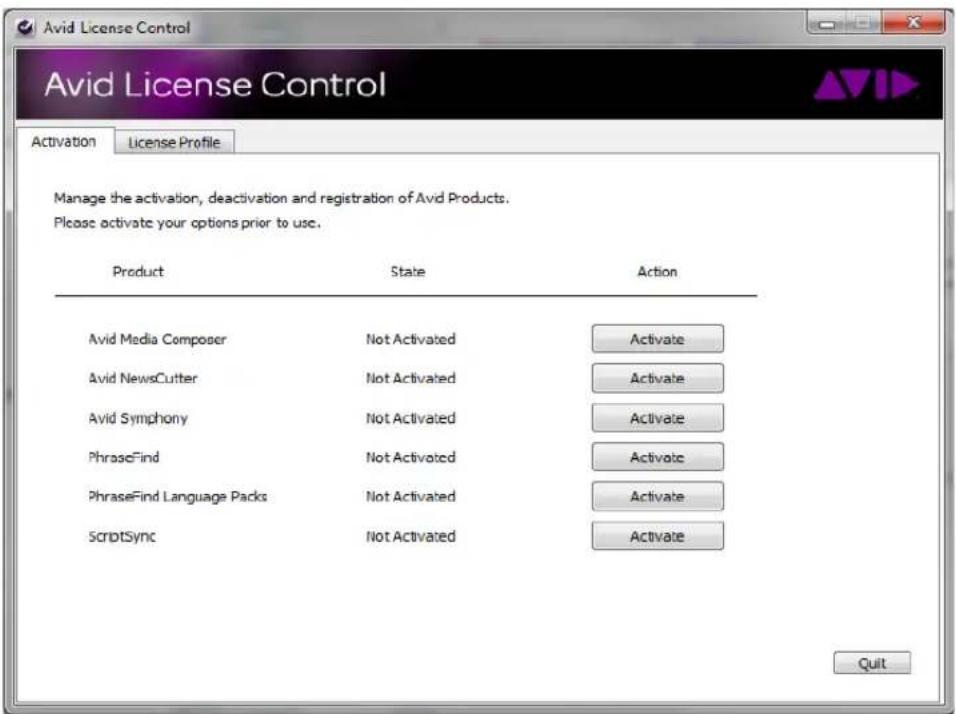
A dialog box opens.
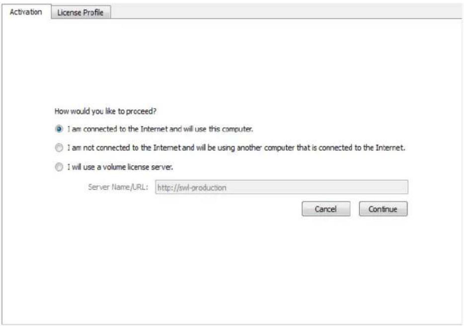
- If your computer has an Internet connection, select "I am connected to the Internet and will use this computer."
- Click Continue.
The Avid Activation dialog box opens.

- Enter your system identification number in the System ID text box.
This number pre-displays if you have activated your Avid editing application. If the System ID does not appear, see “What Will I Need to Activate ScriptSync?” on page 654 for more information.

If you have a dongle attached to your system, the system should pre-display your System ID.
You can copy and paste your system identification number and your Activation ID from a text file to the appropriate text boxes.
- Enter your ScriptSync Activation ID in the Activation ID text box.
Your Activation ID is located on the ScriptSync Instruction letter if you purchased through an Avid Reseller. If you purchased ScriptSync online, you received your Activation ID from Avid by e-mail. For more information, see “What Will I Need to Activate ScriptSync?” on page 654.
- Click Activate.
The Activation tool confirms your system information.
ScriptSync successfully activates.
To activate ScriptSync with the Avid License Control tool and with no Internet connection:
- With the Avid License Control tool opened, click Activate next to ScriptSync.
A dialog box opens.
-
Select "I am not connected to the Internet and will be using another computer that is connected to the Internet."
-
Click Continue.
The Avid Activation dialog box opens.
- On the second computer open a Web browser and navigate to http://avid.com/license.
The Avid Software License Activation page opens.
- In the Software License Activation Web page, enter your Activation ID and if you would like to have your Activation file sent to you, enter your e-mail address.
To find your Activation ID, see “What Will I Need to Activate ScriptSync?” on page 654.
Once the system verifies your Activation ID, the Device ID and System ID entries display.
- Enter your Device ID and System ID.
To find your Device ID or System ID, see “What Will I Need to Activate ScriptSync?” on page 654.
- Click Activate.
The system creates a license.bin file. This file contains license information needed to activate ScriptSync.
If you entered an e-mail address, the .bin file will be sent to you as an attachment. You can also download the .bin file directly from the site.
- Click Download to download the license.bin file to your system.
Depending on your web browser, the license.bin file could be located on your desktop or in a download folder.
- Move the license.bin file to the system you need to activate ScriptSync.
You can use a removable storage device such as a USB drive or you can transfer the data over your network.
-
Open the Avid License Control tool.
-
Click Browse and navigate to the license.bin file you moved to your system, then click Open.
The Avid License Control tool confirms your system information. When the activation is complete, a message informs you that ScriptSync has been successfully activated and the button changes to Deactivate.
Deactivating the ScriptSync License

If you need to move ScriptSync to a different computer, deactivate the ScriptSync license.

You must have an Internet Connection to deactivate ScriptSync.

You do not need to deactivate the Trial version of ScriptSync.
Deactivating ScriptSync
- Open the Avid License Control tool from your Avid editing application. Go to the following location:
(Windows) Start/All Programs/Avid/Utilities/License Control
(Macintosh) Applications/Utilities/Avid Utilities/License Control
The Avid License Control tool opens.
- Next to ScriptSync, click Deactivate.
ScriptSync deactivates and the button changes to Activate.
You will need to follow the instructions on how to activate ScriptSync if you want to activate it on another computer.
Loading and Playing Marked Segments
Once you place marks syncing lines in your script to points in the source clips, you can quickly load and cue takes for selected lines of dialog. You can load a single take, or you can load all the coverage for any given range of lines.
To load the marked segment of a take:
▶Double-click the script mark at the line of dialog that you want to cue.
Your Avid editing application loads the take into the Source monitor, cues it to the synced line of dialog, and places an IN point at the sync location.
To load all the coverage for a range of lines:
- Select the lines in the Script window, dragging through all intersecting takes.
The script lines and takes are highlighted.
- Click the Play button in the Script window if you want to screen the takes for those lines, or click the Record button if you want to add script marks.

Play button (left) and Record button (right)
The takes load and play back one after another. You can use the Tab key or J-K-L keys to jump between takes and to control playback.
Moving or Deleting a Script Mark
When you move a script mark up or down, the mark in the source clip remains at the same frame but is resynced to a new line in the script.
When you remove a script mark, you do not delete the marked portion of the take, only the sync point between the script and the source clip.

You cannot undo the deletion of script marks. To restore a script mark after deletion, see "Placing Script Marks Manually" on page 646.
To move a script mark:
- Press the Ctrl key (Windows) or the Command key (Macintosh) and mouse over the mark in the script.
The pointer changes to a movement indicator.
- Click the mark, and drag it to the new position.
To delete a script mark:
- Click once on a script mark to select it.
You can select multiple script marks for removal by highlighting an entire region of text and selecting the takes containing the script marks you want to remove.
- Press the Delete key.
The Delete dialog box opens.
- Select Delete 1 mark(s), and click OK.
The mark is deleted.
Finding Clips and Script
After you place script marks, which synchronize lines in the Script window to frames in the source clips, you can use the Find Script or Find Bin buttons to search back and forth between the two items.
To find the script linked to a loaded clip:
- Place the position indicator in the clip at the line of dialog (or within a range of dialog) that you want to find.

- Click the Find Script button in the Other tab of the Command palette.
The Script window scrolls to and highlights the portion of script that most closely matches the clip location.
To find source clips and bins:
- Select the takes that you want to find.

- Click the Find Bin button in the Script window toolbar.
Your Avid editing application searches through bins linked to the project, opens the bin containing the linked clips, and highlights them in the bin.
| Name | Take | Duration | |
| 6/9 | 09 | 14;0 | |
| 6/8 | 08 | 16;0 | |
| 6/7 | 07 | 30;2 | |
| 6/6 | 06 | 31;0 | |
| 6/5 | 05 | 33;2 | |
| 6/4 | 04 | 36;0 | |
| 6/3 | 03 | 38;1 |
Editing From the Script Window
To use the Script window most effectively during an editing session, make sure the Script window is fully prepared, including preferred takes, alternative takes (indicated with colors), and script marks for matching lines of text to sync points in the clips.
Consider using the Single Mark Editing option, which lets you skip several steps by performing edits on-the-fly while playing back clips (without marking OUT points). For more information, see “Enabling Single-Mark Editing” on page 587.
For procedures that let you assemble a rough cut quickly from the Script window and to splice clips linked to ranges of script into a sequence, see “Assembling a Rough Cut From the Script Window” on page 665 and “Splicing a Script Range” on page 665.
Revising the Script
During or after each session, or when a scene or segment is completed, the editor or assistant editor can update the Script window to reflect the final edit decisions made during the day. This maintains a complete record of the elements used to construct the scene or segment, as well as all existing alternatives. You can quickly retrieve all the source material in one window whenever you need to make further changes.
Interactive Screenings
The Script window is a valuable tool during screenings of work in progress. You can:
- Quickly search for scenes and pages with clips attached for instant retrieval.
You cannot load sequences into the Script window. Instead, you can perform a video mixdown and load the resulting master clips. For more information, see “Performing a Video Mixdown” in the Help.
- Match back and cue source material to compare alternative takes.
- Quickly find and open bins for retrieval of additional material not included in the Script window.
- Enlarge script font and slate frames for better viewing by your audience.
The Script window provides a visual, interactive look at the content of the original script against the elements in the final piece.
Assembling a Rough Cut From the Script Window
To quickly assemble a rough cut from the Script window:
- Open the Script window for the current cut.
- Double-click the first preferred take to load it into the Source monitor.
Your Avid editing application automatically marks and cues to the IN point. - Play the take until the appropriate OUT point is reached, and stop play.
- Click the Splice-in or the Overwrite button to make the first edit.

Splice-in button (left) and Overwrite button (right)
- Prepare the sequence for the next edit:
a. Create new tracks, if necessary.
b. Enable the appropriate source and record tracks.
c. Patch the tracks, if necessary.
d. Mark an IN point in the sequence for the next edit.
- Double-click the next preferred take to load it.
- Play the clip until you reach the appropriate OUT point, and stop play.
- Perform the edit on-the-fly.
- Repeat steps 5 through 8 until you have moved through the entire scene or segment.
- Fine-tune the edits by using normal trimming and editing procedures. Continue to use the Script window to quickly load and cue alternative takes as necessary.
Splicing a Script Range
You can splice clips linked to ranges of script directly from the Script window into the sequence. To use this feature with accuracy, you should carefully add script marks to the ranges of script during the screening and marking phase. For more information, see “Script Marks” on page 646.
To splice a range:
- Mark an IN point or place the position indicator at the location in the sequence where you want to splice in the segment.
- Press the Ctrl and Alt keys (Windows) or the Command and Option keys (Macintosh). Notice that the Splice-in arrow appears when you point to a take.
- Double-click the preferred take within the range of dialog that is marked with script marks.

The marked section of the clip is spliced into the sequence.
16 Using the Timeline
Your Avid editing application represents each edit and effect on a timeline to help you track and manipulate the elements of your sequence. The Timeline continuously updates as you work, displaying icons and information that you can customize in various ways. The Timeline also has its own set of editing tools for creating and revising edits and transitions across multiple tracks.
The audio and video tracks in the Timeline play in the Record monitor. You can continually edit your sequence and review your changes until you are pleased with the result.
Timeline features are described in the following topics:
- Customizing Timeline Views
• Navigating in the Timeline - Working with Segments
• Working with Multiple Tracks
• In to Out Highlighting in the Timeline - Editing in Heads or Heads Tails View
- Performing a Quick Edit Using the Top and Tail Commands
- Working with Add Edits (Match Frames)
- Dupe Detection
• Editing with the Film Track - Tracking Color Frame Shifts
• Finding Black Holes and Flash Frames - Printing the Timeline
- Activating and Deactivating I/O Hardware
Customizing Timeline Views
You can customize your view of the Timeline to display a variety of information about your sequence as well as the clips and transitions it contains. You can do the following:
- Use options in the Timeline Fast menu to change the display in a variety of ways
For more information, see “Using the Timeline Fast Menu” on page 670 and “Timeline Fast Menu Options” on page 670. - Manipulate the height of tracks or move tracks as part of a view
For more information, see “Enlarging and Reducing Timeline Tracks” on page 672 and “Moving Timeline Tracks” on page 672. - Highlight clips in the Timeline for special purposes
For more information, see “Displaying Clip Colors in the Timeline” on page 672. - Hide or display audio waveforms or pan and gain automation.
For more information, see “Audio Displays in the Timeline” on page 772. - Hide or display the Track Control panel. The Track Control panel defaults to hidden the first time you start your Avid editing application.
For more information, see “Using the Track Control Panel” on page 683. - Save different custom views that you can call up instantly in various circumstances.
For more information, see “Managing Customized Timeline Views” on page 686 and “Using Timeline View Buttons” on page 687.

You can also change your view of the Timeline by using on-the-fly procedures — for example, the Zoom and Focus functions. You cannot save these as part of a Timeline view.
For illustrated examples of custom timeline views, see “Examples of Customized Timeline Views” on page 668.
Examples of Customized Timeline Views
The following table describes several examples of custom timeline views that you might find useful while editing:
Purpose Description
Effects Editing If you are editing complex visuals with multiple tracks and effects, you can display Effect contents, Effect and Dissolve icons, Clip Frames, and Clip Transition Durations within enlarged video tracks in the Timeline.
Purpose Description (Continued)

Complex audio work If you are doing advanced audio work with multiple tracks or fine-tuning difficult audio edits, you can hide video tracks and enlarge audio tracks while displaying waveform plots. If you enable per track settings in the Track Control panel to display waveforms on specific tracks, these settings are not saved in custom Timeline views.

Film and animation editing
If you are working on a film or animation project, you can display the film track, show several frames in the sequence, and display sync breaks where they occur.
| Penguins | Seagull(G) | Seagull(G) | ship |
| Penguins | burning sky(G) | ||
| Penguins | burning sky(G) | ||
| 00:00 01:00:19 00 01:00:20:00 | |||
Editing for online If you are editing offline with plans to generate an EDL and finish the sequence in an online videotape suite, you can track detailed clip and dupe-reel information by displaying and enabling Dupe Detection.
| Avalanche | Penguins.new.01 | BlueCalmWater | Penguins.new.01 | ship into s | Avalar |
| V1 | V1 | V1 | V1 | V1 | V1 |
| 2:06 | 1:28 | 3:07 | 2:08 | 1:02 | 2:06 |
| 2:06 | 1:28 | 3:07 | 2:08 | 1:02 | 2:06 |
| 0/2:06/0 | 0/1:28/0 | 0/3:07/0 | 0/2:08/0 | 0/1:02/0 | 0/2:06 |
| The Big Swell 1 the big | 001 001v01.44f1e86 | The Big Swell 1 the big swv01.43 | 001 001v01.44f1e86a_4 | 001 00143 | The BI |
Purpose Description (Continued)
Basic trimming If you are fine-tuning and trimming simple edits at the early stages of a project, you can view the sequence in Heads and Tails view to see a display of the first and last frame of every clip. You cannot use Trim mode in this view.

natural_image
Six-panel collage showing military scenes: soldiers in combat, fortifications, and a battlefield (no visible text or symbols)Using the Timeline Fast Menu
You can customize the appearance of the Timeline by using various options from the Timeline Fast Menu.
To use the Timeline Fast menu:

Click the Fast Menu button, and select or deselect an option from the menu.
For information on the options, see "Timeline Fast Menu Options" on page 670.
Timeline Fast Menu Options
The following table describes the options available in the Timeline Fast Menu.
Selected options have check marks next to them in the menu. You can select some options only from submenus.
Option Description
Default Setup Returns Timeline display settings to the system default settings; see "Managing Customized Timeline Views" on page 686.
View Type Displays a submenu for selecting different segment display formats; see "Editing in Heads or Heads Tails View" on page 721.
Track Panel Displays or hides the Track Selector panel.
Effect Icons Switches the display of effect icons; see “Changing Timeline View Settings for Effects” in the Help.
Render Ranges Indicates unrendered or partially rendered effects; see "Using Partial Render" in the Help.
Dissolve Icons Switches the display of transition dissolve icons.
Clip Frames Switches the display of start frames for each segment in the Timeline.
| Option | Description (Continued) |
| Clip Text Displays a submenu of clip text display options. | |
| Sync Breaks Displays a submenu of sync break display options; see “Fixing Sync Breaks” on page 610. | |
| Dupe Detection Enables color-coded dupe material display for V1 track; used in 24p projects and matchback projects. See “Dupe Detection” on page 724. | |
| Color Correction Displays indicator lines to show which segments have Source or Program color correction. | |
| Audio Data Displays a submenu for customizing audio tracks with waveforms or volume gain automation; see “Displaying Audio Waveforms” on page 773 and “Displaying Volume and Pan Values” on page 775. | |
| Clip Color Displays and controls the color coding assigned to clips. For more information, see “Displaying Clip Colors in the Timeline” on page 672. | |
| You can also color clips to provide information when you are working in a MultiRez environment. For more information, see “Using Clip Coloring to Show Available Resolutions” on page 1275. | |
| Track Color Displays a palette for changing the color of the tracks in the Timeline; see “Changing the Track Color” on page 676. | |
| A track must be selected in the Timeline for the Track Color command to appear. | |
| Show Markers Displays a submenu for selecting the markers to be displayed in the Timeline; see “Showing Markers in the Timeline” on page 677. | |
| Show Track Displays a submenu for displaying tracks; see “Displaying Timecode Tracks in the Timeline” on page 677. | |
| Track Control Panel | Displays or hides the Track Control panel; see “The Track Control Panel” on page 682. |
| More Detail Expands the Timeline horizontally around the position indicator. | |
| Less Detail Shrinks the Timeline horizontally around the position indicator. | |
| Show Every Frame | Displays every frame in the Timeline if you select Show Track > Film. |
| Show Entire Sequence | Shows the entire sequence within the Timeline. |
| Zoom Back | Restores the Timeline to the previous view before zoom; see “Zooming and Focusing in the Timeline” on page 690. |
| Zoom In | Zooms the Timeline into a detailed view for a selected area; see “Zooming and Focusing in the Timeline” on page 690. |
Enlarging and Reducing Timeline Tracks
You can enlarge or reduce the height of one or more tracks to improve visibility and display more information within the tracks.
To enlarge or reduce the height of tracks:
- Select the tracks in the Timeline that you want to resize.
For more information, see “Selecting Tracks” on page 709.
- Do one of the following:
▶Select Edit > Enlarge Track or Edit > Reduce Track.
▶ Press Ctrl+L (Windows) or Command+L (Macintosh) to enlarge the track, or Ctrl+K (Windows) or Command+K (Macintosh) to reduce the track, which changes the height of all highlighted tracks in the Timeline.
Moving Timeline Tracks
You can move a track to reposition it vertically relative to the Timeline. Surrounding tracks are repositioned above or below the track.

Do not move a track when patching to another track is more appropriate.
To move a track:
▶ Press and hold the Ctrl key (Windows) or Option key (Macintosh), click the Track button for the track that you want to move, and drag the track to its new position.
Displaying Clip Colors in the Timeline
You can use colors to highlight the following types of clips in the Timeline:
- Clips that have offline media.

When you work with nested layers, a clip that contains offline media appears colored even if the missing media is located in a nested layer.
• Clips whose frame rate does not match the sequence frame rate (mixed-rate clips).
- Clips that do not match the video resolution type of the project — for example, HD clips in an SD project, or SD clips in an HD project.
- Clips to which you assign a local color in the Timeline.
- Clips to which you assign a color in the bin.
When working in a MultiRez environment, you can also use colors to track available resolutions.
You can control which types of clip coloring to enable, and customize the colors themselves. Clip color options are saved when you save a customized Timeline View, so you can set up several coloring schemes and then switch between them. For more information, see “Managing Customized Timeline Views” on page 686.
Displaying clip colors overrides any track color you assign from the Timeline Fast menu.
| ship | Penguins.new.01 | BlueCalmWater | Penguins.ne | ship | Avalanche | |
| ship | Penguins.new.01 | BlueCalmWater | Penguins.ne | ship | Avalanche | |
| ship | Penguins.new.01 | BlueCalmWater | Penguins.ne | ship | Avalanche | |
| 00:00 | 01:00:10:00 | |||||

For HD and SD projects, DVCPRO HD clips are colored light red. You cannot customize this color, which is an indicator that DVCPRO HD media plays by skipping frames. To avoid skipped frames, use the Transcode command and select a compatible resolution.
To display clip colors in the Timeline:
- Click the Timeline Fast Menu button, and select Clip Color.
The Clip Color dialog box opens.

2. Select one or more of the following:
Option Description
| Resolution Tracking | Colors clips to indicate the availability of particular resolutions in a MultiRez environment. For more information, see “Using Clip Coloring to Show Available Resolutions” on page 1275.This option is only available if you are working in a MultiRez environment. |
| Offline Colors clips that have offline media.In a MultiRez environment, colors clips that do not match the working resolution, if you have selected Relink to Offline in the Dynamic Relink Settings dialog box. For more information, see “Using Clip Coloring to Show Available Resolutions” on page 1275. | |
| Proxy Colors proxy clips in the Timeline. | |
| AMA Colors AMA clips in the Timeline. | |
| Mixed Rates Colors clips whose frame rates do not match the sequence frame rate.A different color is available for each frame rate. | |
| SD/HD Colors clips that do not match the video definition type of the project format — in an HD project this option colors the SD clips, while in an SD project this colors the HD clips.You can also display clip text that can help you to identify particular clips by selecting Clip Text > Clip Resolutions from the Timeline Fast menu. | |
| Timeline Local Colors clips to which you have assigned a local color in the Timeline.For more information, see “Assigning Local Colors to Clips in the Timeline” on page 676. | |
| Source Colors clips to which you have assigned a color in the bin. (Colors assigned to sequences, groups, motion effects, and title clips do not appear as source colors in the Timeline.) For more information, see “Assigning Colors to Objects in a Bin” on page 341. | |
The order of the options in the Clip Color dialog box indicates the priority order in which your Avid editing application applies colors when you select more than one option. For example, if you have Offline and SD/HD selected, an offline SD clip in an HD project uses the higher-priority Offline color rather than the SD/HD color.
To change the display colors for the Resolution Tracking, Offline, Mixed Rates, or SD/HD options:
- Click the Timeline Fast Menu button, and select Clip Color.
The Clip Color dialog box opens.
- Click the color swatch for the option you want to change.
A color picker grid opens.

- Click a color in the grid.
The color you select becomes the display color for that option.
To reset the display colors for the Resolution Tracking, Offline, Mixed Rates, and SD/HD options:
- Click the Timeline Fast Menu button, and select Clip Color.
The Clip Color dialog box opens.
- Click Default Colors.
The Offline, Mixed Rates, and SD/HD color swatches reset to their default colors.
Changing the Track Color
To change the color of the selected tracks in the Timeline:
- Click in the Timeline to activate it.
- Select the tracks whose color you want to change.
- Click the Timeline Fast Menu button, and select Track Color > color.
- (Option) If you want to choose a custom color for the tracks, press the Alt key (Windows) or Option key (Macintosh) while performing this procedure.
When you release the mouse button on the color palette, the Windows Color dialog box or the Macintosh Colors panel opens.
Assigning Local Colors to Clips in the Timeline
You can assign local colors to clips in the Timeline — for example, to indicate clips that you want to group together or to make clips stand out while you work in the Timeline.
For more information on clip colors in the Timeline, see “Displaying Clip Colors in the Timeline” on page 672.
To assign a local clip color:

- Click the Timeline Fast Menu button, and select Clip Color.
The Clip Color dialog box opens.
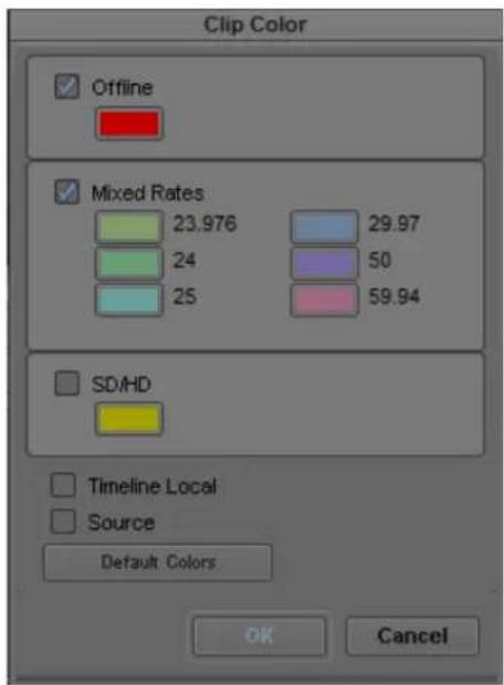

- Select Timeline Local, and then click OK.
- Select one of the segment tools in the Timeline palette, and select a clip you want to color.
- Do one of the following:
Select Edit > Set Local Clip Color > color to select a standard color.
▶ Select Edit > Set Local Clip Color > Pick to select a custom color from the Windows Color dialog box.
The assigned local color appears in the clip in the Timeline.
To remove a local clip color:

- Select one of the segment tools in the Timeline palette, and select the clip whose color you want to remove.
- Select Edit > Set Local Clip Color > None.
The assigned local color no longer appears in the clip in the Timeline.
Displaying Timecode Tracks in the Timeline
When you are working with 24p or 25p projects (PAL with pulldown), you can display separate tracks for 24, 25, 25P, and 30 timecodes in the Timeline. You can also display an edgecode track in the Timeline. By default, the Timeline displays all the tracks. You can hide the timecode tracks by deselecting them in the Show Track submenu of the Timeline Fast menu.
The master timecode also displays in the Timeline ruler above the Timeline.
To customize the tracks to be displayed in the Timeline:
Click the Timeline Fast Menu button, and select Show Track > tracks.

The TC1 track represents the timecode of the active project.
Showing Markers in the Timeline
When you add markers to a sequence, the markers are displayed in the Timeline. You can modify which markers to display in the Timeline by selecting Show Markers from the Timeline Fast menu. When you select a color from the Show Markers submenu, only markers of that color appear in the Timeline. You can select All from the Show Markers submenu to display all the markers, or you can select None to prevent any markers from being displayed in the Timeline.

Show Markers affects only how the marker icons display in the Timeline and does not affect the markers.
To change the display of markers in the Timeline:
- Load a sequence that contains markers into the Record monitor.
- Click the Timeline Fast Menu button, select Show Markers, and then select the colors of the markers you want to display in the Timeline.
The Timeline displays only those markers with the colors you selected.
Setting the Playback Option for the Timeline
You can control how the Timeline displays during playback by setting a preference in the Timeline Settings dialog box:.
- The Timeline display can page to the next section of your sequence when the position indicator gets to the end of the visible section of the Timeline as you play.
- The Timeline display can scroll over the position indicator while you play a sequence
- The Timeline display can remain stationary as the sequence plays, even when the position bar moves beyond the right of the Timeline.

For the Timeline to page or scroll, you might need to display more detail in the Timeline to expand the sequence. Click the slider and drag it to the right to expand the Timeline. All effect icons are hidden as you scroll.
To set the playback option:
- Double-click Timeline in the Settings list in the Project window.
The Timeline Settings dialog box opens, displaying a list of your current Timeline settings. For more information, see “Timeline Settings” on page 1436.
- Click the Display tab, and select one of the following:
▶Page
▶Scroll
▶None
3. Click OK.
Disabling the Smart Tool in the Timeline
Using the Smart tool enables a dynamic, cursor-based editing method in the Timeline. This changes the standard behavior of the mouse pointer so that you cannot scrub through the Timeline as you do in normal edit mode. If you want to move or scrub through the Timeline without making segment edits, you can turn off the editing tools by using the Smart tool toggle bar or by clicking the Timecode ruler or Timecode track to deselect the edit tools if you set this option in the Timeline Settings dialog box.
To disable the Smart tool using the Timecode ruler or the Timecode track:
- Double-click Timeline in the Settings list in the Project window.
The Timeline Settings dialog box opens, displaying a list of your current Timeline settings. For more information, see “Timeline Settings” on page 1436.
- Click the Edit tab, and select Clicking the TC Track or Ruler Disables Smart Tools.
- Click OK.
Using the Full-Screen Timeline
As an alternative to constantly scrolling through the Timeline window or resizing tracks to get a view of the material, you can resize the Timeline window to full-screen display. You can also enlarge the tracks to view complex audio or video layers in greater vertical detail.
A Timeline with reduced tracks wraps around to show more of the sequence. As you reduce tracks in a full-screen Timeline, the sequence wraps around, allowing you to examine a long sequence in greater horizontal detail.

If the Timeline or monitor window is hidden behind another window, select the window again from the Tools menu.
To resize the Timeline window:
▶ Click the Resize box at the lower right corner of the window, and drag it.
▶ (Macintosh only) Click the Maximize button in the top right corner of the window.
The Timeline expands to full-screen size.
To restore a resized Timeline window to its default position:
▶Click the Timeline and select Windows > Home.
To enlarge tracks:
▶ Select the tracks, and press Ctrl+L (Windows) or Command+L (Macintosh).
To reduce tracks:
▶ Select the tracks, and press Ctrl+K (Windows) or Command+K (Macintosh).
You can also continue to work in Source/Record mode by resizing the Timeline window so that it overlaps the Composer window.
You can click either window to activate it and bring it forward at any time, or you can click the title bar of the Timeline window and drag it to the Bin monitor to place each window in its own monitor.
The Timeline Palette
Your Avid editing application provides a quick way to edit sequences in the Timeline without having to enter a specific editing mode such as Trim mode. By using the Timeline palette, you can perform the following editing actions:
- Select and move segments in the Timeline
- Copy and delete segments
- Edit with Lift/Overwrite and Extract/Splice-in edits
- Create single- and dual-roller trims, such as ripple trims and overlap edits
- Adjust transition effects in the Timeline

Timeline palette, located to the left of the Timeline, with the Timeline ruler at the top of the Timeline
The Timeline palette provides you with the most common tools you need for Timeline editing, as well as several buttons you can use to enable editing modes such as Effect mode or Color Correction mode.
Icon Tool Description

Link Selection Allows you to select segments in the Timeline that are linked by common source media and timecode.

Lift/Overwrite Replaces a section of the sequence with the selected source material.
Icon Tool Description
| Extract/Splice-in Inserts marked source material into the sequence without replacing material already in the sequence. | |
| Overwrite Trim Creates a single-roller trim and adds a black segment to fill the duration of trimmed frames. | |
| Ripple Trim Creates a single-roller trim with no sync lock and maintains the duration of all other clips. | |
| Transition Manipulation Allows you to modify transition effects without using the Quick Transition dialog box. | |
| Trim Mode Allows you to enter traditional Trim Mode without selecting a trim tool. | |
| Source/Record mode Enters Source/Record mode. | |
| Effects mode Enters Effects mode, opening the Effect Editor and changing the Record monitor to the Effect Preview monitor. | |
| Color Correction mode Enters Color Correction mode, opening the color correction controls. | |
| Motion Effect Opens the Motion Effect Editor, allowing you to edit Timewarp effects. | |
| Keyframe Selection Lets you select and move audio keyframes in the Timeline. |
The editing tools at the top of the Timeline palette make up the Smart tool. The Smart tool lets you access the most common segment editing tools and to combine functions by selecting multiple tools.
The Smart tool, with all of the functions selected by the toggle bar (left)
The Smart Tool buttons also appear on the Smart Tool tab of the Command palette, so you can map them to the keyboard, a toolbar, or the Tool palette. For more information on mapping buttons, see “Mapping User-Selectable Buttons” on page 112.
When you combine functions on the Timeline palette, you modify how the mouse pointer functions in the Timeline:
- When you select the Lift/Overwrite or Extract/Splice-in button, the mouse pointer changes to a segment edit pointer for either Lift/Overwrite or Extract/Splice-in edits. If you select both buttons, the segment edit depends on which region of the segment in the Timeline that you activate. For more information, see “Working with Segments” on page 693.
- When you select the Overwrite Trim or Ripple Trim button, the mouse pointer changes to a trim roller when you mouse over a transition point and lets you perform the selected trim edit. If you select both trim buttons, the trim edit depends on which region of the transition in the Timeline that you activate. For more information, see “Timeline Trim States” on page 736.
- The Transition Manipulation tool lets you select and modify transition effects in the Timeline. You can adjust the duration and position of the transition effect by moving the effect handles or the effect icon. For more information, see “Adjusting Transitions in the Timeline” in the Help.
- The Smart tool toggle bar lets you turn off the Timeline palette editing tools. When you use the toggle bar to enable Timeline palette tools, the toggle bar enables the tools that you had previously selected.
Since using the Timeline palette tools change the behavior of the mouse pointer in the Timeline, you cannot scrub through the Timeline as you do in normal edit mode. Instead, you can use the Timeline ruler above the Timeline or the Timecode track to move the position indicator. (The Timeline ruler displays the master timecode for your sequence.) If you want to scrub through the Timeline without making segment edits, you can also turn off the segment tools by using the Smart tool toggle bar or by clicking the Timecode ruler or Timecode track to deselect the edit tools if you set this option in the Timeline Settings dialog box (see “Disabling the Smart Tool in the Timeline” on page 678).
The Track Control Panel
Timeline tracks include a Track Control panel that provides features useful when you edit audio tracks. The Track Control panel arranges components in two rows of tools, and it allows you to do the following:
- Show or hide waveforms and clip gain, auto gain, and pan displays on individual tracks (see “Displaying Audio Waveforms” on page 773 and “Displaying Volume and Pan Values” on page 775).
- Add, delete, move, and copy RTAS ^ (Real-Time AudioSuite) effects (see “Real-Time AudioSuite Plug-Ins” on page 918).
- Mark tracks as inactive or solo or mute tracks so you can monitor the audio on a track.

Track Control panel
Component Description
Waveform Turns on or off the waveform display for individual tracks.
Clip Gain/Pan Turns on or off the clip gain, auto gain, and pan display for individual tracks.
Inactive Removes a track from audio monitoring so you can play back your sequence without process the plug-in effects or automation for the inactive track.
Solo Allows you to monitor a single track of audio without deselecting other tracks.
RTAS plug-ins Lists the RTAS plug-ins inserted on the track. Clicking the button for an existing RTAS insert opens the RTAS plug-in window so you can edit the plug-in parameters. Clicking a blank RTAS button opens the RTAS tool so you can insert a plug-in on the track.
Mute Allows you to mute a single track of audio without deselecting it.
Using the Track Control Panel
The Track Control panel displays two rows of tools. If you reduce the size of the Timeline tracks, you might not see the Track Control panel tools. For more information on resizing Timeline tracks, see “Enlarging and Reducing Timeline Tracks” on page 672.”
To show the Track Control panel, do one of the following:
▶ Click the Timeline fast menu and select Track Control Panel. To hide the Track Control panel, deselect Track Control Panel.
▶Click the Track Control Panel button above the Timeline.

Track Control panel, with the Track Control Panel button above the Timeline
Displaying Source Material in the Timeline
You can display source material in the Timeline. This feature is useful when you edit with a sequence or subclip created from a sequence. You can also use it to look at the contents of any source clip in a Timeline display.

Heads and Tails view is disabled when you are displaying material from the Source monitor.
To view multitrack source material quickly in the Timeline for selecting and marking specific tracks:

▶Click the Toggle Source/Record in Timeline button.
By default, the Timeline displays only the available tracks for source material. Both the button and the position indicator turn green to indicate that you are viewing source material.

Displaying the Timeline Top Toolbar
You can display a top toolbar in the Timeline for easy access to editing buttons. You can also map additional buttons to the Timeline top toolbar. For information about mapping buttons, see "Mapping User-Selectable Buttons" on page 112.

To show the Timeline top toolbar:
- In the Project window, double-click the Timeline Setting.
The Timeline Settings dialog box opens. - Select Show Toolbar in the Display tab.
- Click OK.
To hide the Timeline top toolbar:
▶Deselect Show Toolbar, and then click OK.
Managing Customized Timeline Views
You can save a customized Timeline view. Timeline views appear in the Settings list in the Project window. You can save, rename, and copy multiple views.
Your Avid editing application saves the Timeline information from the Timeline Fast menu with each view.
You can select alternate views from the View menu located in the Timeline bottom toolbar. The Timeline view is labeled Untitled until you name and save a customized Timeline view.
You can replace a Timeline view with a different view, while keeping the same name. You can also restore the default Timeline setup at any time.

You can also change the name of a Timeline view or delete a view from the Settings list in the Project window. For more information, see “Naming Settings” on page 1343 and “Deleting Settings” on page 1344.
To name a Timeline view or to change a view's name:
- Click the View Menu button, and select Save As.

The View Name dialog box opens.
- Type a name for the view, and click OK.
- Press and hold the Alt key (Windows) or Option key (Macintosh) while you click the View Menu button to display the list of saved view names, each appended with the Replace command.
- (Option) If you want to replace a Timeline view, select a view name from the list that you want to replace.
Your Avid editing application applies the current Timeline view to the selected name and displays that name in the Settings list in the Project window.
To restore the default view in the Timeline:

▶ Click the Timeline Fast Menu button, and select Default Setup.
Using Timeline View Buttons
The More tab of the Command Palette contains eight Timeline View buttons that you can use to switch between Timeline views. You can map these buttons to any mappable button location or to the keyboard, or you can use them directly in the Command Palette.
You must create at least one Timeline view to use the Timeline View buttons. For more information, see “Managing Customized Timeline Views” on page 686.
The Timeline View buttons are assigned to your Timeline views in the order that they appear on the View menu in the Timeline bottom toolbar and in the Settings list. For example, the T1 button is assigned to the first Timeline view that appears in the menu and the Settings list, the T2 button is assigned to the second view, and so on.
Your Avid editing application sorts the Timeline views alphabetically, and the button assignments might change if you add Timeline views. To keep a designated order, name your Timeline views with a number preceding the first letter (for example, you might have views named 1default, 2headframes, 3waveforms, and so on).
To map a Timeline view button:
- Select Tools > Command Palette.
- Click the More tab.

Timeline View buttons in the More tab of the Command Palette
- Select Button to Button Reassignment.
- Click a Timeline view button (T1 - T8), and drag the button to a location on another palette (for example, the Tool palette) or the Keyboard settings window.
For more information, see "Mapping User-Selectable Buttons" on page 112.
The Timeline view button appears in the new location.
To use a Timeline View button or key, do one of the following:
Click the Timeline view button in the location to which you have mapped it.
▶ Press the key on the keyboard that you have associated with the Timeline View button.
In the More tab of the Command Palette, select Active Palette, and then click the Timeline View button.
Navigating in the Timeline
The Timeline window provides various controls for quickly moving through a sequence and adjusting your view of details displayed in the tracks while editing. You can use the position indicator, the Timeline scroll bar/position bar, the Timeline scale bar, the Zoom In and Zoom Back commands, or the Focus button. In addition, you can highlight marked sections of the sequence for visual reference.
You can also use the Video Quality Menu button in the Timeline bottom toolbar to control the quality level at which media plays back. For more information about the Video Quality Menu button, see “Real-Time Playback of Video Effects” in the Help.
The following illustration shows the Timeline window.

Timeline window: (left to right) Timeline palette, Track Control panel, Position indicator, with the Timeline bottom toolbar under the Timeline (left to right: Timeline Fast Menu, Focus, Toggle Source/Record in Timeline, Video Quality, DNxHD Native, Step In, Step Out, Scale bar Timeline scroll bar)
Understanding the Timeline Position Indicator and Scroll Bar
The position indicator in the Timeline marks your place in the sequence. It also determines how your Avid editing application interprets some of your commands. For example, when you perform an edit, the system takes the location of the position indicator as the In point in the absence of established marks.
When you move the position indicator in the Timeline, the smaller position indicator within the Record monitor's position bar also moves.
By default, the Timeline scroll bar appears on the right side of the Timeline bottom toolbar. You can drag the scroll slider to reposition yourself within the Timeline, or click the arrows to scroll left or right.

Timeline scroll bar with scroll slider at the bottom of the Timeline
You can change the Timeline scroll bar to a position bar that acts like the position bar in the Record monitor, except that you can manipulate it without deactivating the Timeline window. For more information, see “Switching to the Timeline Position Bar” on page 690.

natural_image
Pure horizontal bar with evenly spaced tick marks, no text or symbols presentAn advantage of the position bar is that when you focus on only a portion of the sequence, both the Timeline and Record monitor's position bars show a highlighted region around the position indicator. This represents the range of material displayed in the window.

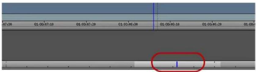
Position indicators with highlighted regions in the monitor and in the Timeline
Switching to the Timeline Position Bar
To switch to the Timeline position bar:
- Double-click Timeline in the Settings list in the Project window.
The Timeline Settings dialog box opens.
- Select the Show Position Bar option in the Display tab.
A check mark appears in the box. To deselect an option, click it again.
- Click OK.
The scroll bar changes to a position bar.

For information on all Timeline settings, see “Timeline Settings” on page 1436.
Zooming and Focusing in the Timeline
You can change your view of the Timeline to focus in on particular information in the following ways:
- You can use the scale bar to stretch and contract the Timeline area centered around the position indicator.
This lets you either zoom in to focus on a specific area of your sequence or zoom out to display your whole sequence. This feature is especially useful when you have a lengthy sequence with many edits.
- You can use the Zoom In command in the Timeline Fast menu to select a portion of the Timeline of any size to instantly expand to fill the window, and the Zoom Back command to instantly restore the Timeline to its former size.
The Zoom In and Zoom Back commands do not depend on the placement of the position indicator. You can select any portion of the Timeline to expand and contract.
- You can use the Focus button to quickly change your view of the Timeline so that you focus on a few seconds of material on either side of the position indicator.
The Focus button centers the position indicator and scales the Timeline so each second of time in the sequence fills 90 pixels in the display. The Focus button is located in the Timeline bottom toolbar next to the Timeline Fast Menu button.

Left to right: Timeline Fast Menu button, Focus button, and scale bar in the Timeline bottom toolbar
To zoom in the Timeline using the scale bar:
- Click the scale slider, and drag it to the right.
The Timeline expands horizontally and shows more detail. The position indicator splits into a solid blue line and a dotted blue line (or “shadow”), marking the beginning and end of the current frame. You can click either the line or the shadow to move exactly one frame forward or back.
- To shrink the Timeline to its original size, drag the scale slider back to the left.
To zoom in the Timeline using the Zoom In and Zoom Back commands:
- Click the Timeline Fast Menu button, and select Zoom In.
The pointer arrow changes to a selection bar.
- Position the pointer at either the start or end of the place you want to zoom in on, and drag to select the section.
When you release the mouse button, the material inside the Zoom In box expands to fill the Timeline window.
- To return to the previous Timeline display, click the Timeline Fast Menu button, and select Zoom Back.
To focus the Timeline using the Focus button:
- Make sure none of the edit tools in the Smart tool is active.
- Move the position indicator to the frame or transition you want to expand.
- Click the Focus button.
Your Avid editing application centers and enlarges the region of the Timeline immediately surrounding the position indicator.
- To return the Timeline to its previous view, click the Focus button again.
Vertical Scrolling in the Timeline
The editing application allows you to automatically scroll vertically in the Timeline. This is useful if you have many tracks in the Timeline and want to scroll below the visible area of the Timeline.
To scroll vertically in the Timeline perform one of the following:
▶ Select the blue bar in the ruler and drag vertically to scroll down the Timeline.
In Segment mode, select a segment and drag vertically to scroll down the Timeline.
▶ Lasso an area above the tracks and drag vertically to scroll down the Timeline.

Controlling Movement in the Timeline
While working in the Timeline window, you can use modifier keys to control the movement of both the position indicator and any segments that you move.
The motion mode indicator in the Timeline toolbar displays a specific icon, depending on the keys you press to facilitate your movement within the Timeline.

Motion Mode Icon Description
| Snaps the position indicator to head frame. | |
| Snaps the position indicator to tail frame. | |
| Snaps the position indicator to the edit point in a track above or below the current track. |
To snap to the head of transitions:
▶ Press the Ctrl key (Windows) or Command key (Macintosh) as you drag either the position indicator or any selected segments.
To snap to the tail of transitions:
▶ Press Ctrl+Alt (Windows) or Command+Option (Macintosh) as you drag either the position indicator or any selected segments.
To snap the selected segments to an edit point in the track above or below the current track:
Click a segment edit button in the Timeline palette, and then press Ctrl+Shift while dragging the segments.
Working with Segments
Your Avid editing application provides editing controls for moving, deleting, marking, and editing entire segments in the Timeline. A segment is a portion of a sequence between two clip transitions.
There are two basic ways to edit segments:
- Select one of the segment tools on the Timeline palette (Lift/Overwrite or Extract/Splice-in). This lets you manipulate segments by positioning the cursor over the segment and performing either a Lift/Overwrite or Extract/Splice-in edit.
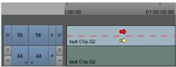
Timeline showing the active segment selection zones
- Select both segment tools on the Timeline palette. This lets you edit segments by positioning the cursor over either the upper half of the segment (for Lift/Overwrite actions) or the lower half of the segment (for Extract/Splice-in actions) and then clicking the segment.
You can also edit directly from a bin, as described in “Bin Editing into the Timeline” on page 705.
Guidelines for Segment Editing
General Guidelines
- Moving a selection with an Extract/Splice-in edit deletes transition effects on either side of the selection. If the selection includes multiple segments around a transition effect, moving the segments preserves transition effects inside the selection.
- You can track the audio while moving segments by pressing the Caps Lock key to enable audio scrub. For more information, see “Using Audio Scrub” on page 768.
- You can select segments linked by common source media and timecode by enabling link selection. For more information, see “Linked Clips” on page 695.
- When you finish making an edit, the active segment tool continues to affect edits you make unless you deactivate the segment tool on the Timeline palette.
Guidelines When Selecting Segments
- You cannot overlap the source and destination tracks. For example, you can move audio segments from A3 and A4 to A1 and A2, but you cannot move them from A3 and A4 to A2 and A3 (A3 overlaps). You can move mono audio tracks only to other mono audio tracks, and you can move stereo audio tracks only to stereo tracks.
- With a group or with linked clips, you can click any selected segment to drag the entire group to a new position.
- You can select black filler as a segment, except when filler is used at the head or tail of a sequence.
Guidelines When Lassoing Segments
- Position the pointer above the tracks before dragging. If you click within the tracks, you either select a segment or a transition (if an edit tool is active on the Timeline palette) or you relocate the position indicator to that position. To lasso segments in the middle of the Timeline between multiple tracks, press and hold the Alt key (Windows) or Option key (Macintosh) while you drag the lasso.
- Lasso at least two transitions or all transitions included in multiple segments. If your lasso surrounds only one transition, you enter Trim mode.
- Drag from left to right. If you drag from right to left, you enter Trim mode with slip rollers selected.
- Link selection does not affect which segments you select when you lasso segments in the Timeline.
Selecting and Deselecting Segments
You can select segments for moving or editing by activating tools on the Timeline palette and then clicking segments in the Timeline, or you can lasso one or more segments. You can also select linked clips when you enable Link Selection. For more information, see “Linked Clips” on page 695.
You can then continue to select or deselect additional segments. The selected segment or group of segments becomes highlighted and remains in its original position during the move until you select its new position.
For additional guidelines when selecting and lassoing segments, see “Guidelines for Segment Editing” on page 693.
To select segments with the pointer:
- Select one of the segment tools on the Timeline palette.

The mouse pointer arrow changes to a large red or yellow arrow when inside the Timeline, depending on where you position the pointer or which segment tool you click.
- Click a segment in any track to select it. Shift+click to select additional segments. You can Shift+click a selected segment to deselect it.
If you have Link Selection enabled, all segments linked to your selection are selected in the Timeline. If you Shift+click a selected segment, all segments linked to your selected are deselected as well.
- (Option) If you enable Link Selection and want to select a single segment and not the segments linked to it, Alt+click (Windows) or Option+click (Macintosh) the segment.
To lasso segments:
▶ Draw a lasso beginning in the area above the tracks in the Timeline. Drag left to right and then down to select more than one segment.


When you draw a lasso, if neither segment tool in the Timeline palette is selected, Lift/Overwrite mode is enabled by default. To switch the mode, click the Extract/Splice-in button, after drawing the lasso.
To deselect one or more selected segments, do one of the following:
To deselect an entire track, click the Track button in the Track Selector panel.
For example, if you lasso segments on V1, V2, and A1, you can click the V2 and A1 Track buttons to leave only the segment on the middle track. V1, selected.
▶ Click one of the segment tools on the Timeline palette, and then Shift+click specific segments on any track.
This deselects the segments you click on any track, leaving the remaining tracks selected. If you have Link Selection enabled, all segments linked to your selection are deselected in the Timeline.
To deselect a linked segment if you have Link Selection enabled, Shift+Alt+click (Windows) or Shift+Option+click (Macintosh) the segment.
Linked Clips
Media objects in bins can contain media on more than one track, such as a master clip with a video track and two audio tracks. When you add media to a sequence that come from the same source and share the same timecode, the Timeline displays the associated tracks. By default, the
Avid editing application treats these tracks as linked so that when you select a segment, the application automatically selects any linked segments. You can select linked clips for both segment editing and trim editing.
The following apply to linked clip selection:
- Track linking affects segments. If you use the same master clip in more than one place in your sequence, each segment maintains its own linking relationship unless the segments overlap in the Timeline.
- When you select a non-video track, clip linking selects only the first appropriate video segment. Other video segments are not selected.
- When you select a trim roller, clip linking selects trim rollers on all linked segments.
• You can turn off linked clip selection in the Timeline by using the Link Selection button. - If you enable Link Selection, you can select a segment without selecting all segments linked to it by Alt+clicking (Windows) or Option+clicking (Macintosh) the segment.
- If you disable Link Selection, you can select a segment and all segments linked to it by Alt+clicking (Windows) or Option+clicking (Macintosh) the segment.
- A video segment cannot link to another video segment.
- Link selection operates across tracks, not along the same track. However, if a video segment links to an audio segment that includes a cut point, link selection operates on both audio segments.
- When two or more video tracks from the same clip overlap in the Timeline and sync is broken with the linked audio segments, link selection links to the video segment with the smallest sync break point.
- When you move a linked clip independently of the tracks to which it is linked so it no longer vertically overlaps the linked segments, the link relationship is broken.
Selecting Linked Clips
Link selection allows you to select segments in the Timeline that are linked by common source media and timecode. When you select a non-video segment that has more than one linked video segment, the video segment closest to the selected segment is selected. If sync breaks exist, the video segment with the smallest sync break is selected.
To enable or disable link selection in the Timeline, do one of the following:

▶Click the Link Selection button.
▶Press Shift+L.
To select linked clips:
- Click a segment with linked clips.
The application selects all linked segments. - (Option) If you want to select additional linked clips, Shift+click additional segments.
- (Option) If you want to deselect selected segments, Shift+Alt+click (Windows) or Shift+Option+click (Macintosh) a linked segment.
Selecting Multiple Segments
Instead of lassoing segments in the Timeline to edit, you can select multiple segments on enabled tracks quickly by using the multiple segment selection buttons in the Edit tab of the Command palette. This allows you to select segments to the left or right of the position indicator, or to select all segments within In and Out marks. The multiple segment edit buttons also appear in the Timeline top toolbar if you create a new user profile (for information on creation user profiles, see “Managing User Profiles” on page 88).
When you use the multiple segment selection buttons, your Avid editing application activates the Segment Extract/Splice-in button if you have not selected one of the segment buttons on the Timeline palette.
You can also use the Shift key to add segments on enabled tracks to the current selection.
To select segments on enabled tracks using the multiple segment selection buttons:
- Move the position indicator to the first or last segment you want to select.
- Select Tools > Command Palette, and click the Edit tab.
- Do one of the following:


Click the Select Left button to select segments under the position bar and all segments to the left.
Click the Select Right button to select segments under the position bar and all segments to the right.
▶ Click the Select In/Out button to select segments intersecting In and Out marks if both marks are present.
If the Timeline has only an In mark or an Out mark, or no In and Out marks, the Select In/Out button selects all segments under the position bar.
Excluding Filler when Selecting Multiple Segments
With this release, you can use a modifier key to exclude filler when selecting multiple segments.
To select segments on enabled tracks using the multiple segment selection buttons:
- Move the position indicator to the first or last segment you want to select.
- Select Tools > Command Palette, and click the Edit tab.
- Do one of the following:


▶ Click the Select Left button to select segments under the position bar and all segments to the left.
Click the Select Right button to select segments under the position bar and all segments to the right.
Click the Select In/Out button to select segments intersecting In and Out marks if both marks are present.
If the Timeline has only an In mark or an Out mark, or no In and Out marks, the Select In/Out button selects all segments under the position bar.
Holding the Alt key (Windows) or Option key (Macintosh) while selecting the Select Left, Select Right, or Select In/Out button will exclude filler from the selection.
Four-Frame Display
When you begin to drag the segments, the interface changes to the four-frame display:
- The Source and Record monitors change to a four-frame monitor display. The two outer frames update while you drag the segment forward or backward in the Timeline, indicating the frames you pass as you drag the segment. The two outer frames in the four-frame display allow you to view and analyze the frames between which you might want to drop the selected segment.
- A centered numeric offset counter appears below the frame monitors. The offset counter tracks the number of frames or feet+frames (24p and 25p projects) that you move while dragging the selected segment from its starting point.

When you drag segments with only the Record monitor displayed, the interface changes to a two-frame display. Only the outer two frames in the four-frame display appear in the Record monitor.

Four-frame display. The two outer frames indicate ending and beginning frames of clips before and after the segment. The two inner frames represent the start and end frames of the segment. The offset counter is highlighted.
When you drag the segments, the original highlighted segment remains in place, while a “ghost” segment enclosed in a dotted white box moves along with the pointer until you release it at a new edit point.
| Man in water | Swimmers | Diver | |
| Man in water | Swimmers | Diver | |
| 00:00 | 01:00:05:00 | 01:00:10:00 | |
When you release the segment into its new position, the actual lift (Overwrite) or extract (Splice-in) occurs. Until then, the segment position is preserved in the Timeline, allowing you to maintain your perspective of the sequence while selecting the new edit point.
Suppressing Four-Frame Display
The four-frame display of incoming or outgoing frames can occasionally slow the movement of segments as you drag them through the sequence. You can improve the speed of segment editing by suppressing the four-frame display.
To suppress the four-frame display:
- Double-click Timeline in the Settings list in the Project window.
The Timeline Settings dialog box opens.
- Deselect the Show Four Frame Display option in the Display tab, and click OK.
- Select one of the segment tools on the Timeline palette.
The mouse pointer arrow changes to a large red or yellow arrow when inside the Timeline, depending on where you position the pointer or which segment tool you click.
- Click the segment, and drag it to its new position.

As you drag the segment, the monitors maintain their Source/Record configuration rather than shift to the four-frame display or two-frame display.
Maintaining Sync with Segment Edits
When you use the Lift/Overwrite tool, the application adds filler to the sequence to maintain sync. When you move segments in the Timeline using Extract/Splice-in, the sync might be broken.
To maintain sync when you use Extract/Splice-in, select the Segment Drag Sync Locks option in the Edit tab of the Timeline Settings dialog box. After you move a segment in the Timeline with Extract/Splice-in, this option maintains sync by adding filler to the following locations:
- Where the segment was moved from in the sequence
- On all other sync-locked tracks that correspond to the new location of the segment you moved
You can move either an audio segment or a video segment. You can also maintain sync for some edits if you enable link selection in the Timeline (see “Linked Clips” on page 695).
To move a segment and keep sync:
-
Double-click Timeline in the Settings list in the Project window.
The Timeline Settings dialog box opens. -
Select the Segment Drag Sync Locks option in the Edit tab.
-
Click OK.
-
In the Track Selector panel, click the Sync Lock button for the video, audio and data tracks that you want to keep in sync.
-
Click the Extract/Splice-in button.
-
Click an audio or video segment, and drag it to the new location.
In the following example, an audio segment in track A2 is moved. The new location for the audio segment has filler added to the video track. All segments remain in sync.


Top: before segment drag sync lock, showing the segment that will move. Bottom: after segment drag sync lock, showing the moved segment and filler added after the move (left), and the filler left in the original location (right).
Moving Segments with Drag and Drop
You cannot move segments to locked tracks. If you attempt to drop a selection on a locked track, the move fails and all selected segments return to their original position in the Timeline.
If you move audio segments, you can only move segments on mono tracks to other mono tracks and segments on stereo tracks to stereo tracks.
To perform a segment edit:
- Do one of the following:

▶ Select both of the segment tools on the Timeline palette, and then position the mouse pointer over the top of the segment (for Lift/Overwrite operations) or the bottom of the segment (for Extract/Splice-in operations).
▶Select one of the segment tools on the Timeline palette.
The mouse pointer arrow changes to a large red or yellow arrow when inside the Timeline, depending on where you position the pointer or which segment tool you click.
- Click the segment you want to move (Shift+click to select multiple segments), and drag it to its new position. If you enable link selection, all linked segments move when you drag the selected segment (see "Selecting Linked Clips" on page 696).
Use the four-frame monitor display, the offset counter, and the segment image in the Timeline to carefully determine the new position. You can also snap to the head or tail of the new edit point (see “Controlling Movement in the Timeline” on page 692).
- Release the mouse button.
If you used the Extract/Splice-in method, the system extracts the selected segment from its old position, closes the gap left by its removal, and then splices the material back into the sequence at the newly selected location.
If you used the Lift/Overwrite method, the system lifts the selected segment from its old position, leaving black filler, and then overwrites the material onto the sequence at the newly selected location.

If the segment contains transition effects, and you move or extract the segment, the transition effect remains. For information about how the system preserves transition effects, see "Transition Effect Preservation" in the Help.
To cancel a segment move, do one of the following:
If you have not dropped the selected segment at a new location, drag the selection out of the Timeline window and release the mouse button.
▶If you have dropped the selected segment at a new location, select Edit > Undo.
Dragging Nonadjacent Segments
You can drag nonadjacent segments in the Timeline. You must be in Overwrite mode to drag the segments.
To drag nonadjacent segments:
-
Make sure you are in Lift/Overwrite mode by selecting the Lift/Overwrite button in the Smart Tool
-
Select the nonadjacent segments that you want to move.
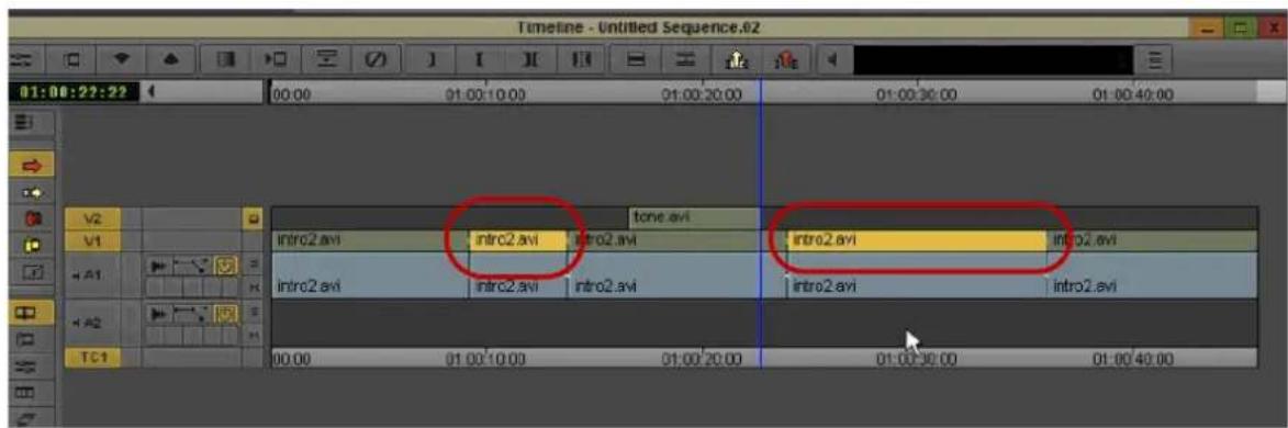
- Move the segments to the desired location.
Deleting Segments
You can use the segment tools in the Timeline palette to delete whole segments in the Timeline quickly without having to mark In and Out points. You can also select multiple segments in separate tracks anywhere along the Timeline to delete them all at once.
By default, your Avid editing application deletes the selected segment and leaves blank space or silence in its place (a Lift segment edit). You can use In and Out points to perform a standard Extract edit.
You can also delete segments by using the Cut command. See “Cutting, Copying, and Pasting in the Timeline” on page 704.
To delete segments quickly:
1. Do one of the following:

▶ Select both of the segment tools on the Timeline palette, and then position the mouse pointer over the top of the segment (for Lift/Overwrite operations) or the bottom of the segment (for Extract/Splice-in operations).
▶Select one of the segment tools on the Timeline palette.
The mouse pointer arrow changes to a large red or yellow arrow when inside the Timeline, depending on where you position the pointer or which segment tool you click.
- Lift/Overwrite (red) deletes the segments but leaves blank space or silence in their place. The total duration of the sequence remains the same, and sync is maintained.
-
Extract/Splice-in (yellow) deletes the segments and closes the remaining gaps. The total duration of the sequence is shortened, and any synchronized tracks lose sync.
-
Select one or multiple segments.
-
Press the Delete key.
The system deletes the segments and any effects applied to them.

If the segment contains transition effects, and you delete the segment, the transition effect remains. For information about how the system preserves transition effects, see “Transition Effect Preservation” in the Help.
Marking Clips and Sequences
As an alternative to marking sections of the Timeline in Source/Record mode for deleting, copying, subclipping, rendering, or creating an EDL or digital cut, you can use the segment tools to mark segments quickly.
To mark segments in the Timeline:
1. Do one of the following:

▶ Select both of the segment tools on the Timeline palette, and then position the mouse pointer over the top of the segment (for Lift/Overwrite operations) or the bottom of the segment (for Extract/Splice-in operations).
▶Select one of the segment tools on the Timeline palette.
The mouse pointer arrow changes to a large red or yellow arrow when inside the Timeline, depending on where you position the pointer or which segment tool you click.
- Click one or more segments to highlight a section of the sequence.
- Click the Mark Clip button.

The system marks an In point at the start and an Out point at the end of the selected segments. If you selected more than one track, the In and Out points mark where the edit points across tracks line up.

Cutting, Copying, and Pasting in the Timeline
You can use the shortcut keys for cutting, copying, and pasting segments selected in the Timeline.
To cut or copy and paste segments:
- Do one of the following:

▶ Select both of the segment tools on the Timeline palette, and then position the mouse pointer over the top of the segment (for Lift/Overwrite operations) or the bottom of the segment (for Extract/Splice-in operations).
▶Select one of the segment tools on the Timeline palette.
The mouse pointer arrow changes to a large red or yellow arrow when inside the Timeline, depending on where you position the pointer or which segment tool you click.
- Click the segment to highlight it.
- Press Ctrl+C (Windows) or Command+C (Macintosh) to copy, or Ctrl+X (Windows) or Command+X (Macintosh) to cut.
- Move the position indicator to the new In point, and press Ctrl+V (Windows) or Command+V (Macintosh) to paste the segment in the Timeline.
If you selected both segment tools in the Timeline palette, the paste operation uses the default segment tool specified in the Timeline Settings dialog box.
Setting the Default Segment Edit Tool
When you perform a segment edit without first selecting a segment edit tool, the Avid editing application uses the default segment tool for the edit. You can use the Timeline Settings dialog box to define which tool to use by default. Selecting a specific segment edit tool in the Timeline palette overrides the default tool.
To set the default tool used for segment editing:
- Double-click Timeline in the Settings list in the Project window.
The Timeline Settings dialog box opens, displaying a list of your current Timeline settings. For more information, see “Timeline Settings” on page 1436.
- Click the Edit tab, and select one of the following:
▶Segment Insert for Extract/Splice-In edits
▶Segment Overwrite for Lift/Overwrite edits
- Click OK.
Enabling Only One Segment Edit Tool at a Time
You can use the Timeline Settings dialog box to specify the behavior of the segment tools in the Timeline palette to allow only one segment tool to be enabled at a time. This overrides the default behavior, which allows both segment tools to be enabled at once, and is useful in some workflows.
For more information on Timeline settings, see “Timeline Settings” on page 1436.
To specify that the segment tools in the Timeline palette be enabled one at a time:
- Double-click Timeline in the Settings list in the Project window.
The Timeline Settings dialog box opens.
-
Click the Edit tab, and select Only One Segment Tool Can Be Enabled At A Time.
-
Click OK
Bin Editing into the Timeline
You can use the segment tools on the Timeline palette to edit clips directly from a bin into the sequence in the Timeline. Bin editing lets you bypass the process of loading clips into the monitor, setting marks, and clicking the Splice-in button or Overwrite button.
You can also use keyboard shortcut keys to edit clips directly from a bin into the sequence in the Timeline.
For information on editing multiple clips directly from the bin into the RecordSource/Record monitor, see “Creating an Instant Rough Cut” on page 582.
To activate bin editing:
- Double-click Bin in the Settings list in the Project window.
The Bin settings dialog box opens. - Select the "Enable edit from bin (Splice, Overwrite)" option.
- Click OK.
To perform a direct edit from a bin into your Timeline:
- (Option) For a more accurate edit, mark In and Out points for each clip or create subclips. Otherwise, the entire clip is edited into the sequence.
- Click one of the segment tools in the Timeline palette:
▶ Lift/Overwrite (red) acts as an overwrite edit, causing the clip to overwrite material of the same length in the sequence while maintaining the same duration of the sequence.
Extract/Splice-in (yellow) acts as a splice edit, inserting the clip into the sequence, moving existing material down, and lengthening the total duration.
If you do not select a segment tool, or if you select both tools, your Avid editing application defaults to the segment tool specified in the Timeline Settings dialog box. For more information, see “Setting the Default Segment Edit Tool” on page 705.
- Drag a clip from the bin into the Timeline.
You can edit only one clip at a time.
The pointer changes to the selected segment icon, and the interface changes to the four-frame monitor display. As you drag, a white outline of the clip indicates the segment position.
- When you find the right placement for the clip, release the mouse button.
The Timeline reflects the new edit. After the edit is completed, the segment tool you selected remains active until you click the active segment tool button to deactivate it.
To perform a direct edit from a bin into a sequence:
- Mark an In or Out point in the Timeline, or move the position indicator to the location where you want the clip to appear.
- Select a clip in the bin.
- Do one of the following:
▶ Press the V key to perform a splice-in edit, which inserts the clip into the sequence and moves existing material down, lengthening the total duration of the sequence.
▶ Press the B key to perform an overwrite edit, which causes the clip to overwrite material of the same length in the sequence while maintaining the same duration of the sequence.
The Timeline reflects the new edit.
Working with Multiple Tracks
Your Avid editing application lets you edit up to 24 tracks of video and 24 tracks of audio, including multichannel audio tracks, and one data track. While working with multiple tracks, you can use the Track Selector panel to select, manipulate, delete, lock, patch, and monitor your tracks. You can use multiple tracks to layer audio effects and sound or to add video titles and other effects.
Multichannel audio tracks contain more than one channel of audio in a single track. Stereo multichannel tracks, for example, contain two stereo channels in one track. You can edit multichannel audio tracks in the same way that you edit mono audio tracks.

Multiple video tracks do not immediately play back at the same time until you apply an appropriate effect that composites the layers. Multiple audio layers, however, do play back immediately if correctly monitored.
Occasionally, effects editing involves a procedure known as nesting. Nesting involves stepping into existing tracks to reveal added layers for combining multiple images and digital video effects. When you apply an effect, you can step out to view and render the effect as one segment on the track. You can nest up to 24 additional tracks within each track.

For more information on nesting techniques, see “Nesting Effects” in the Help.
Understanding the Track Selector Panel
The Track Selector panel provides a quick display of track information. You can see which tracks are available, active, patched, monitored, or locked on the source and record sides at any time. The Track Selector panel can look very different depending on the nature of the source material or the work underway in the sequence. The following configuration shows only one example.

You cannot patch a data (D) track.
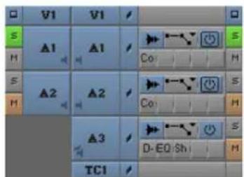
Track Selector and Track Control panels, with Source tracks (left) and Record tracks (right). See the following table for a list of Track Selector buttons.
Icon Button
| ☐ | Video Track Monitor button |
| VI | Video Track, Source and Record |
| ✓ | Sync Lock button |
| ✓ | Audio Mono Track Monitor button |
| ✓ | Audio Stereo Track Monitor button |
| 5 | Audio 5.1 Surround Track Monitor button |
| 7 | Audio 7.1 Surround Track Monitor button |
| AI | Audio Track, Source and Record |
| TCI | Timecode button |
The source side of the panel displays only those tracks available for the clip currently loaded. For example, a clip that has audio captured only for track A1 does not display an A2 track in the Track Selector panel.
The record side of the panel displays only those tracks currently in use for the sequence. When you edit source material with a track selected that does not yet exist on the record side, by default the track appears on the record side after the edit takes place.
Selecting Tracks
You can select tracks on the source side or the record side of the Track Selector panel to control your options for editing. For example, you might select the source and record tracks for V1, A1, and A2 to edit picture and audio from the source clip into the sequence. To edit the picture without sound, select only V1 source and record tracks. To edit the sound without the picture, select only A1 and A2 source and record tracks.
The following guidelines apply to track selection when you edit:
- You can edit selected tracks on the source side directly into the sequence, assuming you have selected parallel tracks on the record side.
- You cannot edit deselected tracks on the source side into the sequence, regardless of record track selections.
- You cannot edit deselected tracks on the record side into the sequence, regardless of source track selections.
The Tracks tab of the Command Palette contains buttons for all available Timeline tracks. You can map these buttons to any mappable button location or to the keyboard, or you can use them directly in the Command Palette. For more information, see “Mapping User-Selectable Buttons” on page 112 and “Activating Commands from the Command Palette” on page 114.

Track buttons in the Tracks tab of the Command Palette
To select one or more tracks, do one of the following:
▶ Click the Track button of any inactive track to select the track.
Drag a lasso around multiple tracks to select them at once.
With the Timeline active, select Edit > Select All Tracks to select all tracks on the record and source sides.
Click the Cycle Picture/Sound button in the Edit tab of the Command palette to cycle among selected video tracks, audio tracks, data track, or all tracks.

To use a Command Palette button for track selection, do one of the following:
- Click the appropriate button in the location to which you have mapped it.
- Press the key on the keyboard that you have associated with the track button.
- In the Tracks tab of the Command Palette, select Active Palette, and then click the track button.
To deselect a track:
▶Click the Track button of any active track.
Understanding Track Monitoring
The following information describes how track monitoring functions and your options for monitoring tracks. For procedures on monitoring or soloing tracks, see “Monitoring and Soloing Tracks” on page 712.
Monitoring Video
The Video Track Monitor button determines whether you see video during playback. You can turn it off at any time to monitor only audio during editing. When there are multiple video tracks, all tracks below the monitored track are active during playback. The Video Track Monitor button displays a Monitor icon when the track is monitored for playback and output.
When you edit with multiple tracks, you can activate the monitoring of a lower track to monitor only the video on that track and below. You can use this feature when you have multiple layers of video effects and need to isolate lower tracks for viewing. You can also monitor a solo track.

If you monitor a video track below the topmost track, return monitoring to the topmost track to view, export, mix down, or record all the tracks together. Unmonitored tracks are not included in playback.
Monitoring Audio
You can monitor up to 16 audio tracks at a time.
The following characteristics apply to audio track monitoring:
- The system pans odd-numbered mono tracks to the left speaker and even-numbered mono tracks to the right speaker by default. Stereo tracks include channels for the left and right speakers, with the stereo mix panned to the center.
- If your sequence includes more than 16 audio tracks, you can select any 16 tracks to monitor at one time by selecting the Audio Track Monitor button for each audio track you want to monitor. The Audio Track Monitor button displays either with a black border (primary monitored audio track) or without the black border (monitored audio track), when you select the audio track for monitoring playback and output.
- An Audio Track Monitor button with a black border indicates that the tracks are the primary monitored tracks and audio information is not dropped when the play speed increases during scrubbing. By default, the Avid editing application sets the two top audio tracks as the primary monitored tracks. For more information about setting an audio track to ensure it is not dropped during scrubbing, see “Selecting Tracks for Audio Scrubbing” on page 769.
- To hear more than 16 tracks at once, you must mix down some of them to a maximum of 16. For more information, see “Mixing Down Audio Tracks” on page 835.
- By default, all monitored audio tracks are selected for scrubbing. To isolate specific audio tracks for scrubbing, see “Soloing Audio Tracks” on page 767.
- By default, Direct Out maps all audio tracks in numerical sequence to existing output channels.
- You can customize the output of audio tracks, as described in “Setting Audio Output Options” on page 1056.
Advantages of Solo Monitoring
When editing, you can isolate individual video or audio tracks for monitoring without having to deselect monitoring of all other tracks.
Solo monitoring provides several advantages:
- You can eliminate slow cueing and playback when working with a complex sequence by monitoring a specific track.
- You can view any individual layer of a composited effect.
- You can isolate an individual audio track with a single mouse click (without manually deselecting the other audio tracks).
- You can isolate audio tracks for audio scrubbing without having to deselect monitoring of all other audio tracks.
Monitoring and Soloing Tracks
The Track Monitor buttons allow you to choose which tracks to monitor in the Source monitor, the Record monitor, and the speakers. You can monitor a single track or monitor multiple tracks at the same time. You can also isolate, or solo, an individual track for monitoring without having to deselect other tracks.
For more information on monitoring video and audio tracks, and on the benefits of solo monitoring, see “Understanding Track Monitoring” on page 710.

You cannot monitor or solo a data (D) track.
To activate or deactivate monitoring for a track:
Click the Track Monitor button for the track on either the source-side or the record-side.

Track Selection panel, with video and audio tracks selected for monitoring
To select a track for solo monitoring:
- Ctrl+click (Windows) or Command+click (Macintosh) the Track Monitor button for the video track you want to solo monitor.
- Click the Solo button for the audio track you want to solo monitor.
The Track Monitor button changes to green with a black Monitor icon (video track) and the Solo button changes to green (audio track) to indicate solo monitoring. The Mute button on all other audio tracks changes to orange.
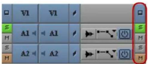
Track Selection panel, with video and audio tracks selected for solo monitoring
To deselect solo monitoring:
▶Click the Track Monitor button or the Solo button again.
Patching Tracks
When working with multiple tracks, you can encounter a circumstance in which you must edit source audio or video onto a track other than the parallel track displayed in the Track Selector panel. To edit the source material onto another record track above or below it, you must patch the source track to the targeted record track.
You can perform only one patch per edit, but there is no limit on the number of times you can patch from the same source track. Audio can patch only to audio, and video only to video. Also, you can only patch multichannel audio tracks to multichannel audio tracks, or mono tracks to mono tracks. Your Avid editing application dims the track selector buttons on tracks with unsupported track formats when you patch tracks.

You can also patch tracks by using the Auto-Patching option in the Edit tab of the Timeline Settings dialog box. For more information, see “Timeline Settings” on page 1436.

When you patch from one video track to another, the Video Track Monitor icon moves to the track you are patching to if you selected the Auto-Monitoring option in the Edit tab of the Timeline Settings dialog box. Return to monitoring the topmost track, when necessary, to play back and output all video tracks.

You cannot patch a data (D1) track to another track.
To patch a track:
Drag from a source track (audio or video) to the targeted record track (a white arrow appears during the patch). You can also drag from a record track to a targeted source track.
Track selection buttons for tracks with unsupported track formats dim as you drag the source track to a record track and you cannot patch to those tracks. For example, if you patch a source mono audio track, then all record stereo and record video tracks are disabled and you can only patch to a record mono audio track.

If you move the mouse pointer over a track selector button, and then press and hold the mouse button, a list of available tracks displays.

Audio patch from a source track to an audio record track (left) and the new source track order identifying the patch (right).

After you patch tracks, it is helpful to display the destination track of the clips in the Timeline. Select Clip Text > Clip Tracks from the Timeline Fast menu to display the destination track.
To undo a patch:
- Click in the Record monitor or Timeline.
- Select Special > Restore Default Patch, or manually repatch to the previous track.
The selected source track moves beside the record track to which it is patched as soon as you draw the arrow and release the mouse. The patched track remains highlighted in preparation for your edit. You can proceed to select any other tracks required for the edit.
After you make the edit, you can continue to work on the same track or patch to a different track as necessary.
Understanding Locking and Sync Locking
Your Avid editing application provides two ways of locking tracks, locking tracks and sync locking tracks. You can sync lock selected tracks so that trimming one track also trims the other tracks. Sync locking is useful when you work with multiple tracks and want to maintain sync between two or more tracks.
Locking tracks prevents further editing from being performed on them and can help in the following workflows:
- For video or picture editing, you can lock tracks when you have completed a set of complex, multilayer edits and want to avoid making accidental changes while you work on adjacent tracks.
- For audio editing, you can lock audio tracks containing sync dialog that should be maintained while you edit adjacent video tracks or audio tracks.
- For projects involving multiple editors, you can lock tracks to prevent unnecessary or accidental changes.

For more information on using the sync lock feature in Trim mode, see "Understanding Sync Lock" on page 610.
The Sync Lock and Lock buttons of the Track Selector panel display different icons for sync-locked and locked tracks. For more information on applying the locks, see “Locking and Sync Locking Tracks” on page 715.
Locking and Sync Locking Tracks
The following illustration shows the location of the Sync Lock and Lock buttons in the Track Selector panel, and the icons that appear on these buttons. For more information on your options for locking tracks, see “Understanding Locking and Sync Locking” on page 714.

Top to bottom: Lock icon, Sync Lock icon, and Sync Lock All button in the Track Selector panel
To lock tracks:
- Select the tracks you want to lock (Source, Record, or both).
- Do one of the following:
▶Select Clip > Lock Tracks.
▶Right-click in the Timeline, and select Lock Tracks.
If you want to lock a single track, right-click the track selector button and select Lock Track.
The Lock icon indicates that the selected tracks are locked. No further editing can occur on locked tracks until you unlock them.
To unlock tracks:
- Select the tracks you want to unlock.
- Do one of the following:
▶Select Clip > Unlock Tracks.
▶Right-click in the Timeline, and select Unlock Tracks.
If you want to unlock a single track, right-click the track selector button and select Unlock Track.
The Lock icon disappears and the tracks are unlocked.
To sync lock tracks, do one of the following:
Click a Sync Lock button to activate the Sync Lock icon for each synchronized track.
▶Click the Sync Lock All button to switch sync lock on and off for all tracks.
To resume editing on individual tracks:
▶Click a Sync Lock button or the Sync Lock All button to remove the Sync Lock icon.
Adding and Deleting Tracks
Your Avid editing application lets you create up to 24 video and 24 audio tracks in the Timeline when building a sequence. (You can monitor 16 audio tracks at a time.) You can also add a data track, which is used for ancillary data. For more information, see “Preserving HD Closed Captioning and Ancillary Data” on page 1091.
By default, new tracks are numbered consecutively. For example, if a sequence contains video tracks numbered V1 and V2, a new video track is numbered V3. However, you can customize the numbering, and you can also assign custom names to tracks.
You can remove one or more tracks from a sequence if you no longer need the tracks. When you delete a track, you remove it permanently from the sequence. If you want to remove the track temporarily, hide the tracks as described in “Customizing Timeline Views” on page 668.
To add a new track to a sequence, do one of the following:
With a sequence loaded in the Record monitor, select the type of track you want to add:
- Select Clip > New Video Track.
- Select Clip > New Audio Track Mono.
- Select Clip > New Audio Track Stereo.
- Select Clip > New Meta Track.
- Select Clip > New Data Track.
▶Right-click in the Timeline, and select one of the following:
- New Video Track.
- New Audio Track Mono.
-
New Audio Track Stereo.
-
N e w M e t a T r a c k .
- N e w D a t a T r a c k .
The new track appears in the Timeline.
To add a new track to a sequence and customize its numbering:
- Press and hold the Alt key (Windows) or Option key (Macintosh) and select the type of track you want to add:
▶Select Clip > New Video Track.
▶Select Clip > New Audio Track Mono.
▶ Select Clip > New Audio Track Stereo.
▶Select Clip > New Meta Track.
▶Select Clip > New Data Track.
The Add Track dialog box opens.

- (Option) Select the type of track you want to add (for example, a video or an audio stereo track) by clicking the Track Type menu, and selecting that option.
- (Option) Select a track number other than the default number displayed in the dialog box by selecting another number from the Track Number menu.
- Click OK.
One of the following occurs:
- The new track appears in the Timeline and in the Track Selector panel. Stereo tracks in the Timeline display with a horizontal divider, indicating two channels of audio.
- If you selected the number of an existing track in step 3, a dialog box asks if you want to insert the new track. Click Insert to add the new track below the current track with that number. Your Avid editing application labels the new track with the number you selected and renumbers the existing tracks in consecutive order.
To add a custom name to a track in the Timeline:
- Right-click the Track Selector button, and select Rename Track.
The Comments window opens. - Type a new name for the track.
- Click OK.
To remove a custom track name:
- Right-click the Track Selector button, and select Rename Track.
The Comments window opens. - Click Remove.
The track name returns to the default track name, such as V1.
To delete one or more tracks from a sequence:
- Click one or more Track Selector buttons to select the tracks you want to delete.
- Press the Delete key.
The Delete Track(s) dialog box opens.
- Click OK.
The tracks are deleted.
Splitting Stereo Tracks to Mono Tracks
You can split a stereo audio track in the Timeline into separate mono tracks if you want to edit separate audio channels or if you need to export a sequence either to an older version of the Avid editing application. You can also split a clip or sequence with stereo tracks to mono from a bin. You can split individual stereo tracks to mono, or you can split all stereo tracks in your sequence.
When you split a stereo track, the original stereo track becomes a mono track and a new mono track is added below the original track. For example, if you split a stereo track on A1 in the Timeline, the application makes A1 a mono track holding one stereo channel and adds a second mono track on A2 for the other stereo channel. If A2 already exists in the Timeline, the application renumbers tracks to allow for the split mono tracks. Also, the application renumbers tracks to preserve the odd and even track numbers for left and right mono channels. Renumbered tracks start at the highest track available.
If you duplicate a clip in a bin and split the copy to mono, or if you edit a stereo clip into a sequence on multiple tracks and split one track to mono, your sequence can contain both a stereo and a mono instance of the same master clip. This does not cause a problem with editing, playback, or any other operation.

If splitting stereo tracks to mono tracks causes your sequence to exceed 24 audio tracks, or if splitting to mono cannot maintain the relative order of tracks or the left/right channel alignment, the Avid editing application cannot complete the operation and an error message displays. You can reduce the number of audio tracks in your sequence and retry the operation.

Stereo track A4 (left) split into mono tracks A4 and A5 (right)
When the Avid editing application splits a stereo track to two mono tracks, it changes some audio properties of the track:
- Removes stereo track effects such as RTAS plug-in effects.
- Converts stereo AudioSuite plug-in effects to mono effects.
• Applies any existing gain automation to the resulting mono tracks. - Applies any existing pan automation to the resulting mono tracks, panning odd-numbered tracks to the left and even-numbered tracks to the right.
- Clears rendered effects. If you have effects on audio segments on stereo tracks, you need to render them after splitting the tracks to mono.
When you split all tracks in a sequence to mono, the Avid editing application automatically duplicates your original sequence and saves a copy to your bin before splitting stereo tracks to mono.
To split a stereo audio track to mono, do the following:
▶ Right-click the stereo track you want to split, and select Split Track to Mono.
Right-click a stereo clip in a bin that you want to split, and select Split Track to Mono.
The stereo track splits into two mono tracks, with the second mono track added below the original stereo track. A copy of your original sequence is saved to your bin as [sequence_name].Copy.[number].
To split all stereo audio tracks in the Timeline to mono, do one of the following:
▶Right-click in the Timeline, and select Split All Tracks to Mono.
▶Select Clip > Split All Tracks to Mono.
All stereo tracks in the Timeline split into two separate mono tracks, with the new mono tracks added below each original stereo track. . A copy of your original sequence is saved to your bin as [sequence_name].Copy.[number].
Backtiming Edits
Backtiming an edit is effectively the reverse of the process you normally use for marking footage: instead of marking from the In points forward, you mark according to the Out points. For example, you might have a track of audio (music or voice) that ends at a specific point, and you want to synchronize a video clip to end on a particular clip. You can backtime the edit to match the end points of the tracks.
Consider the following:
- Your Avid editing application needs only three marks to perform a backtimed edit. The In and Out points set on the record side always take precedence.
- If you do not mark an In point in the sequence, your Avid editing application uses the In point and Out point in the source clip (if both are marked) to determine the In point in the sequence. If you do not set both marks in the source clip, the system uses the position indicator as the In point.
- If you do not mark an Out point in the clip and an Out point in the sequence, your Avid editing application uses the end of the source clip as the Out point.
- If you mark Out points in both the Source monitor and in the Record monitor, your Avid editing application uses the Out point on the record side.
To backtime an edit:
- Mark In and Out points in the sequence where you want the edit to start and end.
- Select the appropriate tracks.
- Load the source clip into the Source monitor.
- Mark an Out point for the source clip to synchronize to the Out point in the sequence.
- Click the Overwrite button.
The source material is added to the sequence, with the synchronized ending.
In to Out Highlighting in the Timeline
When you mark a sequence with In to Out points, the system indicates the selection by highlighting the marked region on selected tracks in the Timeline.

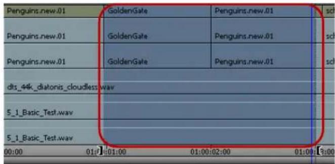
Marked region highlighting in the Timeline
This visual guide helps you monitor track and segment selection more carefully when mixing or applying effects across multiple tracks and segments.
To turn the highlighting feature on and off:
Select the Show Marked Region option in the Display tab of the Timeline Settings dialog box.
Editing in Heads or Heads Tails View
While in the early stages of editing a project, you can rearrange clips in the sequence visually by using Heads view or Heads Tails view. These display formats are useful for rearranging simple straight-cut edits.

If you rearrange a split edit (in which the audio extends beyond the video, or the reverse), the system cuts all tracks to the same edit point. To rearrange split edits or edits on multiple video tracks, or to move audio and video separately, use the Segment editing techniques described in “Working with Segments” on page 693.
To edit in Heads view or Heads Tails view:
- Click the Track buttons to select the tracks to be edited.
- Click the Timeline Fast Menu button, and select View Type > Heads or Heads Tails.
The Timeline changes to one of the following displays.

natural_image
Four outdoor scenes showing textured ground, a stone structure with cutouts, and a green forest (no visible text or symbols)
natural_image
Six-panel collage showing outdoor scenes: a person in a suit, a rocky terrain, a green object, a vehicle, and a distant landscape (no visible text or symbols)Heads view (top) and Heads Tails view (bottom) in the Timeline. Heads view shows the Head frame for each clip. Heads Tails view shows both the head and tail frames for each clip.
- Press and hold the Alt key (Windows) or Option key (Macintosh), click the frames representing the clip you want to move, and drag the clip to its new position.
The sequence is rearranged to match the changes you made.
Performing a Quick Edit Using the Top and Tail Commands
The Top and Tail commands let you perform quick edits to segments in the Timeline.
Use the Top button in the Edit tab of the Command palette to extract footage from the start of the clip or segment to the position indicator. This action is equivalent to the T-R-X keyboard command sequence: Mark Clip, Mark Out, Extract.
Use the Tail button in the Edit tab of the Command palette to extract footage from the position indicator to the end of the clip or segment. This action is equivalent to the T-E-X keyboard command sequence: Mark Clip, Mark In, Extract.
For information about how the Mark Clip button works, see “Marking an Entire Clip or Segment” on page 520.
To edit using the Top and Tail commands:
-
Load a sequence into a monitor.
-
Select the track or tracks you want to edit, and deselect all other tracks.
-
Move the position indicator to the location where you want to perform an edit.
-
Do one of the following:

Click the Top button to extract footage from the start of the clip or segment to the position indicator.

Click the Tail button to extract footage from the position indicator to the end of the clip or segment.
Working with Add Edits (Match Frames)
The Add Edit function places an artificial edit point between frames of a clip. The edit appears in the Timeline as a transition between two clips, but when you play the clip, the footage appears unchanged because the frames are continuous. This form of edit is also known as a match frame.
You use add edits primarily to isolate a portion of a clip or sequence, which lets you modify that portion without affecting the rest of the footage. You can also add edits to filler segments to maintain sync while trimming. Once you make the adjustment, playback of the clip is no longer seamless because the two portions of the clip are different.
You can add an edit to a single audio or video track, or you can place the Add Edit across several tracks at once. You can add an edit to all tracks with filler, regardless of the track selection.
The Add Edit button appears in the Edit tab of the Command palette. Depending on the model of your Avid editing application and your button mappings, it might appear in other locations such as the Tool palette or the Timeline top toolbar. You can also map the Add Edit button to a custom location. For more information, see “Mapping User-Selectable Buttons” on page 112.
If you make a mistake when adding an edit, or if you have finished performing edit functions with multiple Add Edits and want to remove them, you can remove all Add Edits in the entire sequence or within a selected portion of the sequence.
You can also remove individual match frames by using the Undo command, or by selecting them in Trim mode and pressing the Delete key. For more information, see “Undoing or Redoing Edits” on page 583 and “Working with Trim Edits” on page 732.

You cannot remove match-frame edits between segments in which segment effects and audio pan or volume adjustments have been applied.
To add a match-frame edit:
- Move the position indicator to the selected frame.
- Select the tracks where you want to add the edit.
- Click the Add Edit button.
The edit appears in the sequence with an equal sign to indicate a match frame.


By default, the match-frame indicator is white. If a change in level occurs, the match-frame indicator changes to red.
To add an edit to filler clips at the position indicator:
- Move the position indicator to the selected frame.
- Alt+click (Windows) or Option+click (Macintosh) the Add Edit button.
The edit appears on all tracks with filler in the sequence at the position indicator.
To remove match-frame edits:
- Select the entire sequence or a portion of it as follows:
▶Select the entire sequence by removing any In and Out points.
▶ Select a portion of the sequence by marking an In point and an Out point surrounding the match-frame edits (Add Edits) you want to remove.
- Select the tracks from which you want to remove the edits.
- Select Clip > Remove Match Frame Edits.
Your Avid editing application removes the edits.
Dupe Detection
When you edit offline with plans to generate an EDL, the Dupe Detection feature lets you visually track duplicate frames of footage while editing so that you can eliminate or manage the requirements of an online dupe reel.

The Dupe Detection feature works only for track V1.
When you activate Dupe Detection, each set of duplicate frames is tagged with a different color. (Up to 10 color sets can be distinguished during a single detection process.) Matching frames have matching colors. You can use any of the Trim Mode options to remove the duplicate frames, if necessary.
The colored bars that distinguish duplicate frames in the sequence appear automatically above the frames in the Timeline.

Two duplicate frames marked above the clip in the Timeline by the automatic Dupe Detection feature
Orange bars mark the first set of duplicate frames, green bars mark the second set, and so on. You can use Dupe Detection while you edit to locate duplicate frames, and remove them as the sequence evolves.
Activating Dupe Detection

You can change the handle size used by Dupe Detection in the Edit tab of the Timeline Settings dialog box. For more information, see “Adjusting Handle Length in Dupe Detection” on page 727.

Your Avid editing application might mark a special effect optical (such as a blowup) as a duplicate frame. Double-check your sequence for this possibility before deleting frames.
To activate Dupe Detection:
Click the Timeline Fast Menu button, and select Dupe Detection.
Dupe Detection occurs instantaneously and retroactively; if duplicate frames already exist in your sequence, the colored bars appear immediately. As you edit, your Avid editing application dynamically displays the duplicate frames.
Methods for Changing Handle Length in Dupe Detection
In 35mm film editing (using the single-strand method), one extra frame, known as the safety frame, provides tabs for the negative cutter to use when cutting two segments of film together. However, this frame is always lost during the negative conform.

Example of a splice on a safety frame. Frames 1 and 3 are still usable, but frame 2 has been cut in the middle and is lost.
In 16mm film editing (using the multiple-strand method), labs sometimes use the zero-frame cutting method to avoid seeing each splice in a 35mm blowup print. In this method, the negative is conformed along with the handles so that the cuts appear as soft frame handles rather than jumps in the resulting 35mm blowup.
Different labs have different standards depending on the equipment used. Usually, a minimum of four frame handles is needed.

natural_image
Three identical film strip frames arranged in a row, each with blank square cutouts (no text or symbols)Example of zero-frame cutting with multiple strands. The handles are shown in lighter gray.
Adding specific handle lengths to dupes (as they appear both in the sequence and in film lists) has the following advantages:
- In 35mm single-strand conforming — Editors can better track duplicate frames and provide the negative cutter with more than one safety frame to avoid losing specific frames.
- In 16mm multiple-strand conforming — For labs using the zero-frame cutting method, editors can track the number of handles during editing according to the specific standards of a particular lab.
Adjusting Handle Length in Dupe Detection
To adjust handle lengths in Dupe Detection:
- Double-click Timeline in the Settings list in the Project window.
The Timeline Settings dialog box opens.
-
Click the Dupe Detection Handles menu in the Edit tab, and select the number of handle frames. The typical 35mm safety frame setting is 0.5 frame (amounting to a 1-frame total with both sides of a cut).
-
Click OK.
The selected value is applied to the head and tail of every event.
When you enable Dupe Detection during editing, the handles are added to the colored dupe indicators that appear in the Timeline.
Editing with the Film Track
You can use the film track to examine each frame of the sequence in a linear display, much as you would when looking at a strand of film on a flatbed or workbench. Unlike your view of the footage in the monitors, that display one frame at a time, the film track within the Timeline lets you compare individual frames side by side within a range of frames.
To display the film track:
▶Click the Timeline Fast Menu button, and select Show Track > Film.
A row of film frames appears at the top of the Timeline. The film track displays as many representative frames as possible within the window.

Film track in the Timeline
To adjust your view of the Timeline quickly for frame-by-frame viewing and editing:
Click the Timeline Fast Menu button, and select Show Every Frame.
The film track displays frames for the topmost video track only. You cannot display more than one film track at a time.
To quickly view more frames as you scroll:
▶Drag the resize box in the lower right corner of the Timeline for a full-screen view.
You can reduce the size of Timeline tracks to wrap the sequence around several times.
As you continue to scroll, each strand of the Timeline wraparound is updated.
Tracking Color Frame Shifts
In preparation for an online edit using 1-inch reel-to-reel sources, you can enable the Color Framing options to track and correct instances where an edit cuts between the four fields (two frames) required to create a complete NTSC color sync signal phase (or eight fields — four frames — required for PAL).
When you enable Color Framing, green bars appear above the Overwrite and Splice-in buttons (Source and Record monitors) or above the position bar which blink whenever a color sync signal is interrupted by an edit. The blinking lights indicate that color framing is out of phase at the edit transition.

Color-frame phase bars above the position bar
To enable color-frame tracking while editing:
- Double-click Composer in the Settings list in the Project window.
The Composer Settings dialog box opens.
- Click the Color Framing menu in the Edit tab, and select the appropriate option:
▶For NTSC video, select 4-field.
▶For PAL video, select 8-field.
- Click OK to complete the setting selection.
To correct color-frame interruption as you edit:
- Note any edits that cause the green lights to blink.
You can adjust the edits now or place markers to return to these edits and correct them later.
- To adjust the edit, enter Trim mode.
In Trim mode, your Avid editing application displays small green boxes at the top corners of adjacent frames. When the color sync signals are in phase, the boxes align horizontally.

natural_image
Two empty rectangular panels with two small gray squares placed vertically (no text or symbols)Example of color-framing boxes. Top: color sync signals are in phase and the boxes align horizontally. Bottom: color-sync signals are out of phase.
- Trim one frame at a time on one side of the transition or the other until the green boxes align and the color-frame phase bars stop blinking.
If you pay attention to color framing while editing, you do not need to think about it when assembling your master tape. If you ignore color framing during the edit session, you might have to make adjustments during online editing if your edits interrupted any color-frame fields in the sequence.
Finding Black Holes and Flash Frames
You can use the Find Black Holes and Find Flash Frames commands to help you quickly find parts of your sequence that you might want to delete from the final sequence:
Black holes are segments of the sequence consisting of one or more frames of filler. Flash frames are clips with an extremely short duration — for example, fewer than 10 frames.
To find black holes:
- Click the Timeline to activate it.
- Select the tracks you want to search.
- Move the position indicator to the beginning of the sequence or before the part of the sequence you want to search.
- Select Clip > Find Black Holes.
The position indicator moves to the first segment that contains filler. You can then edit or delete the filler, if necessary.
To find the next segment that contains filler:
▶Select Clip > Find Black Holes again.
To find flash frames:
- Set the maximum frame length that you want to detect:
a. In the Project window, double-click the Timeline Setting.
The Timeline Settings dialog box opens.
b. Click the Edit tab.
c. In the option Find Flash Frames Shorter Than, type the maximum number of frames you want to detect. The default is 10, which indicates the system will detect clips with 9 or fewer frames.
d. Click OK.
- Click the Timeline to activate it.
- Select the tracks you want to search.
- Move the position indicator to the beginning of the sequence or before the part of the sequence you want to search.
- Select Clip > Find Flash Frames.
The position indicator moves to the first flash frame.
To find the next flash frame:
▶Select Clip > Find Flash Frames again.
Printing the Timeline
To print the Timeline:
- Click the Timeline to activate it.
- Select File > Print Timeline.
The Print dialog box opens. The name of the printer and details of the dialog box vary, depending on your facility.
- Select the Print options.
- Click OK (Windows) or Print (Macintosh).
Your Avid editing application prints the current view of the Timeline. You can also use the Print Timeline command to print the Timeline in Heads view or in Heads Tails view.
Activating and Deactivating I/O Hardware
The editing application includes a hardware toggle button in the Timeline. This allows you to switch between hardware and software editing modes. The hardware toggle button appears in the Timeline if I/O hardware is attached when you launch the editing application. This includes Avid Nitris DX and Mojo DX hardware and 3rd party Open I/O hardware. This feature allows you to enable and disable the hardware for use with other software, for example After Effects. This also allows you to access certain software only features such as Full Screen Play.

The editing application will automatically release the hardware if you switch to another application. It will be reactivated when you switch back to the editing application.

Activating and Deactivating I/O Hardware
If the Toggle Hardware button is enabled, the I/O hardware is active. If the Toggle Hardware button is disabled, the I/O hardware is inactive.
To activate the I/O hardware:
Click the Toggle Hardware button until it is active. The button is gray when hardware is active. This puts the editing application in Hardware mode.
To deactivate the I/O hardware:

Click the Toggle button until it is inactive. The button has a red circle and line through it when inactive. This puts the editing application in Software mode.
Certain settings and buttons in the editing application change depending upon which mode you are in. For example, the Toggle Client Monitor button is disabled when the editing application is in Software mode. And you have access to additional Audio Project Output, Video Input and Video Output options when the editing application is in Hardware mode.

The I/O third party vendors are working on updating their plugins to work with the Toggle Hardware feature. Your current third party plugins will work properly with this version of the editing application, but if you try and use the Toggle Hardware button without updated plugins, you might need to reboot the system to reacquire your hardware.
17 Working with Trim Edits
Basic editing of a sequence initially produces a rough cut, which is loosely defined as a series of straight-cut edits with many rough edges and few effects. After creating a rough cut, you can use trim edits to fine-tune the transitions between each clip or between whole segments. You can also trim edits as you build a sequence rather than create a rough cut first. The following sections describe trim editing procedures:
- Trimming with the Timeline Palette
• Understanding Trim Displays - Setting Small Trim Display
- Trim Settings Overview
• Timeline Trim States - Selecting Trim Sides
- Overwrite Trimming
- Ripple Trimming
- Dual-Roller Trimming
- Refining Trims
- Reviewing Trim Edits
- Trimming On-the-Fly
• Using Dual-Image Playback During Trims - Trimming During a Playback Loop
- Creating Overlap Edits
- Extending an Edit
- Maintaining Sync While Trimming
- Slipping or Sliding Segments
• Using the Transition Corner Display
Trimming with the Timeline Palette
You can perform trim edits by using the trim tools on the Timeline palette. This lets you create trims quickly in your sequence which you can later fine-tune by using the advanced functionality of trimming.
You can make the following basic kinds of trim edits using the Timeline palette:
• Overwrite trim — single-roller trims which either add black or overwrite frames while trimming
- Ripple trim — single-roller trims with no sync lock
- Dual-roller trim — edits that move the transition boundary between segments without affecting the duration of the sequence
Some trims, such as overwrite trim edits, maintain sync between video and audio clips. Other trims, such as ripple trims, might break sync. For more information on keeping video and audio clips in sync, see “Maintaining Sync While Trimming” on page 751.
The following limitations apply to trim edits:
- You cannot trim a clip so that its duration equals zero frames.
- You can only trim until you encounter another segment in the same track. If you trim multiple clips, you can trim until any of the transitions encounters a segment in the same track or until the reach the duration of the shortest clip in the group.
- You cannot perform an overwrite trim beyond the duration of the selected clip.
Understanding Trim Displays
Different trim displays provide unique sets of controls for fine-tuning edits with various trim procedures. You can perform many of the same functions from any of these trim displays, such as removing and adding frames or slipping and sliding segments. For information about accessing these modes, see “Trim Settings Overview” on page 736.

You can render transition effects while trimming, but you cannot render segment effects once you select a transition for trimming. If the position indicator is on a segment effect or if the marked portion of your sequence includes a segment effect, you cannot access Render menu commands and buttons.
Small Trim Display
Small Trim display leaves the monitor display intact and has smaller displays of outgoing and incoming frames.

Small Trim display — replaces Record monitor in two-monitor view. Outgoing and incoming frames appear side-by-side on the right, with playback loop parameter controls above them, and with frame offset counters and Trim buttons beneath them.
Quick Trim Display
If you display only the Record monitor (for example, as you review the final version of a sequence), you can use Quick Trim display for making quick adjustments to transitions in your sequence.
Like Small Trim display, Quick Trim display replaces the Record monitor with smaller displays of outgoing and incoming frames.

Quick Trim display — replaces Record monitor in single monitor view. Outgoing and incoming frames appear side-by-side on the right, with playback loop parameter controls above them, and with frame offset counters and Trim buttons beneath them.

When you click the Trim Mode button with the Record monitor active, the system enters Big Trim display. If you click the Trim Mode button again, the interface switches back to the Record monitor. This toggle feature is useful if you like to trim quickly as you finish your sequence.
Big Trim Display
Big Trim display replaces the Source and Record monitors with displays of outgoing and incoming frames. Big Trim display also shows transition playback loop parameters.

Big Trim display — replaces both monitors in two-monitor view. Outgoing frames appear on the left and incoming frames appear on the right. Bottom, left to right: Playback loop parameter controls, frame offset counters, and Trim buttons.
Setting Small Trim Display
When you click the Trim Mode button from Source/Record mode, by default the system activates Big Trim display. If you want to keep the Source monitor displayed, you can enter Small Trim display, which lets you access the Source monitor controls.
To set Small Trim display:
- Double-click Trim in the Settings list in the Project window.
The Trim Settings dialog box opens.
- Click the Features tab and select "Always use Small Trim mode."
Your Avid editing application defaults to Small Trim display when you use the Trim Mode button.
Trim Settings Overview
You can customize how trimming works from the Trim Settings dialog box. The Trim Settings dialog box has two tabs: Features and Play Loop. The Play Loop feature continuously replays the last trim you performed for review purposes.
You can learn about specific Trim settings as follows:
- For setting some default behavior for trimming, see “Dual-Roller Trimming” on page 744.
- For information on transition playback loop parameters, see “Trimming During a Playback Loop” on page 748.
- For information on dual-image playback during trims, see “Using Dual-Image Playback During Trims” on page 748.
- For more information about the Play Loop feature, see “Reviewing Trim Edits” on page 746.
For information about all Trim settings, see “Trim Settings” on page 1440. For general information on accessing and working with settings, see “Working with Settings” on page 1339.
You can also do the following:
- Map trim-related buttons onto palettes or the keyboard, as described in “Understanding Button Mapping” on page 110.
- Configure a Trim-mode-specific Timeline view, as described in “Customizing Timeline Views” on page 668.
Timeline Trim States
When you trim using the Timeline palette, the kind of edit you can perform depends on which trim tools you select and the position of the mouse pointer relative to the transition you want to trim. If you enable both the Overwrite Trim and Ripple Trim tools and then hover the pointer over the upper half of your clip, you can perform an overwrite trim edit on either the outgoing frames (A-side) or the incoming frames (B-side). When you hover the pointer over the lower half of your clip, you can perform a ripple trim. Positioning the pointer over the transition between clips lets you perform a dual-roller trim.
When you select one of the trim tools on the Timeline palette, you can perform only that type of trim on your sequence.
The trim edit buttons also appear on the Smart Tool tab of the Command palette, so you can map them to the keyboard, a toolbar, or the Tool palette. For more information on mapping buttons, see “Mapping User-Selectable Buttons” on page 112.
As you move the pointer back and forth across a transition, notice that the roller icon changes from an A-side roller (facing left), to a dual roller, to a B-side roller (facing right) to indicate the type of trim.

natural_image
Diagram showing a road with vehicles and a red crosshair, no text or symbols presentTrim icons for the outgoing frames of the A-side clip (left) and the incoming frames of the B-side clip (right)
The following table describes the kinds of trim you can perform in each zone adjacent to your transition.
Icon Trim Type Trim Zone

Overwrite trim (outgoing) Upper right corner of the outgoing clip

Overwrite trim (incoming) Upper left corner of the incoming clip

Ripple trim (outgoing) Lower right corner of the outgoing clip

Ripple trim (incoming) Lower left corner of the incoming clip

Dual-roller trim Transition between outgoing and incoming clips
Selecting Trim Sides
You can trim a transition on either the outgoing side (A-side or tail), the incoming side (B-side or head), or both sides (dual-roller).
Once you select a trim side, the following happens:
• The selected parts of the transition are highlighted
- The corresponding rollers appear in the Timeline, colored to represent the type of trim: red for overwrite trim, yellow for ripple trim, and pink for dual-roller trim. This provides visual feedback so you always know what type of trim you can perform.
Single trim rollers: Overwrite trim selected (left), Ripple trim selected (center), Dual-roller trim selected (right)
- Your Avid editing application highlights one or both of the frame counter indicators below the monitors to reflect the active trim sides: A-side, B-side, or both. The number indicates the frames added to or subtracted from the transition.
When you clear your trim selections, the trim tools remain active. You can turn off the trim tools by clicking the trim tool buttons in the Timeline palette or by clicking the Smart tool toggle bar.
You can use different methods to select a transition for trimming. The optimal selection method depends on your workflow.
To select the sides of a transition to trim, do one of the following:
Select one or both of the trim tools on the Timeline palette, and then click the outgoing (A-side) or incoming (B-side) monitor to define which side of the transition to trim. The pointer changes to an overwrite trim or an ripple trim icon over either the A-side or the B-side of the transition, depending on the position of the pointer.
Use the Trim buttons in the Trim tab in the Command palette or the Trim keys on the keyboard to select side A, side B, or both. You can map these buttons to other locations, as described in “Mapping User-Selectable Buttons” on page 112.
▶ Use the Cycle Trim Sides button to cycle between selection for a single transition of the A-side, B-side, or both.
▶ Lasso a transition to select both sides of a transition for trimming. If you lasso multiple transitions from left to right, you select the segment and not the transitions. If you lasso multiple segments from right to left, you select transitions for slip trim.
▶ Use one of the keyboard shortcut keys to select both sides of a transition relative to the position indicator:

Shortcut Key Selection
U Nearest transition
A Previous transition
Shortcut Key Selection
S Next transition
Use the Trim Counter frame indicators located below the monitors. Click the A-side or B-side of a frame indicator to select single-roller trimming, or Shift+click both frame indicators to select dual-roller trimming.

The Trim Counter frame indicators: A-side (left) and B-side (right). The counter is purple when the side is active.
To clear trim selections, do one of the following:
Click the Smart tool toggle bar to turn off the Timeline palette Smart tools.
▶Click the Trim mode button.
▶Click the Source/Record Mode or the Effect Mode button.

Source/Record Mode button (left) and Effect Mode button (right)
▶Click a frame step, or press the Right Arrow key or Left Arrow key.
Click a location in the Timecode (TC1) track at the bottom of the Timeline or the Timeline ruler at the top of the Timeline.
The position indicator moves to that location.


Click in the TC1 track to clear trim rollers and relocate the position indicator
Selecting Video Tracks for Trimming
When you click the outgoing (A-side) or incoming (B-side) monitor with a transition selected for trimming, or the A-side or B-side of a transition in the Timeline, all trim rollers are set to the selected side. You can modify this behavior to select only the video tracks for trimming.
To change only the trim rollers on the video tracks:
Alt+click (Windows) or Option+click (Macintosh) either the outgoing monitor or incoming monitor, or either the A-side or the B-side.
The trim rollers change only on the video tracks.
To return to the last position of the trim rollers:

▶Press the Alt key when you click the Trim Mode button.
Selecting Additional Transitions
You can select additional transitions for trimming in different contexts.
To quickly select additional transitions on contiguous tracks for trimming on the same side:
▶ Click the corresponding Record track buttons in the Track Selector panel.
For more information, see "Selecting Tracks" on page 709.
For example, if you select a single transition in track V1 for single-roller A-side trimming and want to add tracks A1 and A2 at the same transition, click the corresponding track selectors.
You can also deselect tracks in the Track Selector panel to remove transitions on those tracks from the trim procedure.
To select additional transitions for single-roller trimming in varying locations on different tracks:
▶Shift+click the transitions in the Timeline.
This method is useful when you work with staggered transitions across multiple tracks. This also lets you select both A-side and B-side transitions for simultaneous trimming in opposite directions (asymmetrical trim). You cannot do this with dual-roller trims.
| school of fish | low angle ice shot | Penguins |
| school of fish | low angle ice shot | Penguins |
| school of fish | low angle ice shot | Penguins |
| 01:00:20:00 | 01:00:2 | |
Example of two A-sides and one B-side selected for asymmetrical trimming
To quickly add multiple transitions to the currently selected transitions:
▶ Press and hold the Shift key, and lasso the additional transitions.
You can select and trim two heads or tails simultaneously, in any combination, for each track in the sequence. All selected transitions are trimmed the same number of frames. This lets you save time and, in some cases, maintain sync by performing a single-trim procedure across multiple tracks and transitions.
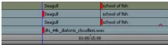
Tail frames on two clips selected for simultaneous trimming across an overlap edit
To select transitions on clips linked by common source and timecode:

- Click the Link Selection button.
- Click a selection with linked clips.
The application selects all transitions on linked segments.
For more information on link selection, see "Linked Clips" on page 695.
Soloing Audio while Trimming
Soloing audio lets you listen to a single audio track while trimming multiple tracks.
To solo an audio track while trimming, do the following:

▶Click the Solo button in the Track Control panel for the track you want to solo.
The Solo button turns green, and Mute buttons on all other audio tracks turn orange.
Overwrite Trimming
If you want to trim one side of a transition but still maintain synchronization between video and audio, you can create an overwrite trim on either the A-side (outgoing frames) or the B-side (incoming frames) of a transition while maintaining the overall duration of the track and the sync relationships. This procedure either adds a black segment or overwrites frames to fill the duration of trimmed frames. For more information on preserving sync by adding black filler, see “Maintaining Sync While Trimming” on page 751.
You can lasso transitions in the Timeline to select more than one transition for trimming. This method is useful when you need to select multiple transitions staggered across parallel tracks (overlap cuts) for simultaneous trimming.
If you enable link selection, clicking a transition also selects transitions on linked segments (see "Linked Clips" on page 695).
To perform and overwrite trim:
1. Do one of the following:
▶ Select the Overwrite Trim tool on the Timeline palette, and then click a transition to select it for trimming. Shift+click to select multiple clips aligned at the same transition.
▶ Select the Overwrite Trim tool on the Timeline palette, and then lasso the transitions in the Timeline.
Draw the lasso by clicking at a point above the top track in the Timeline and dragging to surround the transitions. You can drag from right to left or left to right to lasso one transition across several contiguous tracks. Avoid lassoing more than one transition on a single track because lassoing left to right selects the segment and activates segment editing tools, and lassoing right to left activates slip trim.

To select transitions located below several track layers, you can draw a lasso within the Timeline by pressing and holding the Alt key (Windows) or Option key (Macintosh) while you drag.
If you selected both the Overwrite Trim tool and the Ripple Trim tool on the Timeline palette, position the mouse pointer over the upper corner of either the outgoing or incoming clip next to the transition you want to trim and click the transition to select it for trimming. Shift+click to select multiple clips aligned at the same transition.
The cursor changes to a red single-roller trim icon, and the transition displays red trim rollers.

2. Click and drag in the direction you want to trim.
The new incoming frame displays in the Record monitor as you trim, and one of the following occurs:
- If you trim from an A-side trim handle toward the outgoing segment or from a B-side trim handle to the incoming segment, black filler is added.
- If you trim from an A-side trim handle toward the incoming segment or from a B-side trim handle to the outgoing segment, frames are added to the segment with the trim handle and removed from the other segment.
After you add black filler to a video track, you can replace the filler with footage by performing a replace edit. For more information, see “Performing a Replace Edit” on page 586.
Ripple Trimming
If you make a single-roller trim on either the outgoing or the incoming frames of your transition on an unlocked track, you can move the rest of the your sequence in the direction of the trimmed segment while maintaining the duration of all other clips. Ripple trims “ripple” the effects of your trim along the sequence. However, ripple trims can change the duration of your sequence if you select all tracks, and it can break synchronization with any unselected track. For more information about preserving sync, see “Maintaining Sync While Trimming” on page 751.
You can lasso transitions in the Timeline to select more than one transition for trimming. This method is useful when you need to select multiple transitions staggered across parallel tracks (overlap cuts) for simultaneous trimming.
If you enable link selection, clicking a transition also selects transitions on linked segments (see "Selecting Linked Clips" on page 696).
To perform a ripple trim:
- Do one of the following:
▶ Select the Ripple Trim tool on the Timeline palette, and then click a transition to select it for trimming. Shift+click to select multiple clips aligned at the same transition.
▶ Select the Ripple Trim tool on the Timeline palette, and then lasso the transitions in the Timeline.
Draw the lasso by clicking at a point above the top track in the Timeline and dragging to surround the transitions. You can drag from right to left or left to right to lasso one transition across several contiguous tracks. Avoid lassoing more than one transition on a single track because lassoing left to right selects the segment and activates segment editing tools, and lassoing right to left activates slip trim.

To select transitions located below several track layers, you can draw a lasso within the Timeline by pressing and holding the Alt key (Windows) or Option key (Macintosh) while you drag.
If you selected both the Ripple Trim tool and the Overwrite Trim tool on the Timeline palette, position the mouse pointer over the lower corner of either the outgoing or incoming clip next to the transition you want to trim and click the transition to select it for trimming. Shift+click to select multiple clips aligned at the same transition.
The cursor changes to a yellow single-roller trim icon, and the transition displays yellow trim rollers.

- Click and drag in the direction you want to trim.
The new outgoing frame displays in the Source monitor as you trim, and all segments located on the selected tracks move with the trim.
Dual-Roller Trimming
Using a dual-roller trim allows you to move the transition point between segments without changing the duration of the sequence. This adds frames to one side of the transition and subtracts them from the other side.
There are several ways to select a transition for dual-roller trimming. Which method you use depends on your editing workflow.
If you enable link selection, clicking a transition also selects transitions on linked segments (see "Selecting Linked Clips" on page 696).
To select a transition for dual-roller trimming, do one of the following:

▶ Position the mouse pointer over the transition you want to trim so the pointer changes to a dual-roller icon, and click the transition.

▶Click the Trim Mode button.
Your Avid editing application selects the transition nearest the position indicator for dual-roller trimming. The dual-roller icon appears on all highlighted tracks. This method is useful for selecting straight-cut transitions on one track or across video and audio tracks.
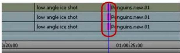
Default trim selection for a straight cut (showing dual-roller icons)
If you selected the option in the Trim Settings dialog box to "Auto focus when entering Trim mode," the Timeline enlarges at the transition selected for trimming.
If the transitions are not straight cuts (overlap cuts or L-edits), the dual-roller icon appears only on the transition nearest the position indicator of the topmost track, and all other tracks are deselected.
Alt+click (Windows) or Option+click (Macintosh) the Trim Mode button to select the previous trim roller configurations.
By default, when you click the Trim Mode button, the trim rollers are set for dual-roller trimming. For more information about selecting trim sides, see "Selecting Trim Sides" on page 737.
▶ Click the Go to Previous Edit or Go to Next Edit button.

By default, the system selects the nearest transition in either direction of the selected track for dual-roller trimming.
If the transitions are a straight cut, the system selects all selected tracks. If the nearest transition is an overlap edit with staggered transition points, the system selects the next transition where all selected tracks have transitions at the same point.

▶ Click the Play Loop button on a palette twice, or press the Play Loop key on the keyboard twice.
When you click the Play Loop button once, the system plays the transition in a playback loop. Clicking the Play Loop button a second time stops the playback.
This method is useful if you want to trim quickly as you edit, going back and forth between trimming and other edit modes. The action takes you to the last trimmed transition. For more information on this method, see “Trimming During a Playback Loop” on page 748.

The Play Loop button does not appear in Source/Record mode by default. You must map it to the keyboard or a palette in advance. For information on button mapping, see “Understanding Button Mapping” on page 110.
Refining Trims
After you select your transitions and trim sides, you can make your trim more accurate by using the advanced features of trim editing.
To refine a trim, do one of the following:
▶ Use the Trim buttons to trim forward or backward by 1-frame or 10-frame (NTSC or PAL) or by 1-frame or 8-frame (24p) increments.

Left to right: Trim Backward 10 Frames (or 8 Frames) button, Trim Backward 1 Frame button, Trim Forward 1 Frame button, Trim Forward 10 Frames (or 8 Frames) button
▶Use the J-K-L keys to trim forward or backward in the sequence.
▶ Use the numeric keypad at the right side of the keyboard, as follows:
- To move the transition a specific number of frames, type a plus sign (+) or minus sign (−) and the number of frames (from 1 to 99), and then press Enter. If the number of frames exceeds 99, type an f after the number to indicate frame count. For example, to enter 200 frames, type 200f and press Enter.
- To move the transition to an exact point in the timecode, type a timecode number larger than 99, including frames. For example, type 102 to enter 1 second and 2 frames (1:02).
For greater control while performing a trim, do one of the following:
▶Press Ctrl+Alt (Windows) or press the Command+Option key (Macintosh) as you drag one frame at a time.
▶Press the Ctrl key (Windows) or Command key (Macintosh) to snap to other transition points.
As you trim, all selected transitions in the Timeline move in unison. The Trim counter displays the frame count backward or forward for one or both trim sides, and the monitors display the new incoming or outgoing frames.
Reviewing Trim Edits
You can review an edit by using the Play Loop button or the Edit Review button.
The Edit Review button (in the Play tab of the Command Palette) lets you review an edit or other change that you made to a transition. You can set how far the position indicator moves backward by using the Preroll option in the Play Loop tab of the Trim Settings dialog box. For more information, see “Trim Settings Overview” on page 736.

Using the Edit Review command causes your Avid editing application to deselect trim rollers on all transitions.
To review the most recent trim edit or to play the currently selected transition:

- (Option) To see the Timeline in a closer view while you review the trim, click the Focus button. (To return to your original view of the Timeline, click the Focus button again.)
You can also select an option in the Features tab of the Trim Settings dialog box to focus the Timeline automatically when you select a transition by entering trim mode with no trim edits or trim tools selected. For more information, see “Trim Settings: Features Tab” on page 1441.

- Click the Play Loop button.
The system enters a playback loop. This loop begins at a preroll point before the transition and ends at a postroll point.
- Modify the length of the preroll, postroll, and transition effect duration by clicking the appropriate timing text box and typing a new value.

Preroll length text box (top left), postroll length text box (top right), and transition effect duration text box (bottom)

You must display two rows of buttons in the Composer window to see the trim controls. For more information, see “Composer Settings” on page 1367.
- To stop the playback loop, click the Play Loop button again.
- To deselect trim points, click the Source/Record Mode button.
To review footage starting from the previous transition:
- Move the position indicator to the transition you want to review.
- Click the Edit Review button.
The position indicator moves before the previous transition and begins to play.
In a sequence with multiple selected tracks, the Edit Review command moves the position indicator before the first set of edits that line up on all the selected tracks.
- To stop play, press the space bar.
Trimming On-the-Fly
You can use the J-K-L keys on the keyboard to play outgoing or incoming material and mark trim points. This is similar to the procedure for marking footage on-the-fly, as described in “Marking and Subcataloging Footage” on page 518.
For convenience, this method isolates the trim controls to just three keys.

When trimming with the J-K-L keys, you cannot completely trim away all frames in a segment. Your Avid editing application always leaves one frame. To remove the remaining frame, see "Refining Trims" on page 745.
To trim on-the-fly:
- Click either the outgoing (A-side) or incoming (B-side) monitor to play in real time during the trim.
- Select one or more transitions for overwrite trimming, ripple trimming, or dual-roller trimming.
For more information, see “Selecting Trim Sides” on page 737.
- Use the J-K-L keys to step (jog), play, or shuttle through the footage at varying speeds:
▶ Press and hold the K key while pressing the J or L key to step slowly backward or forward through the footage. When you find the frame where you want to relocate the transition, release the K key to complete the trim.
Press the J or L key once to play at normal speed, or more than once to shuttle at higher speeds. When you see the frame where you want to relocate the transition, press the space bar or the K key to complete the trim.
The monitors and the Timeline update to reflect the trim.
Using Dual-Image Playback During Trims
Dual-image playback lets you view A-side and B-side frames in real time while performing a trim. You can play through the transition by using the J-K-L keys or the Play and Trim buttons.

Using the Dual Image Play option disables real-time effects.
To use dual-image playback during trims:
- Double-click Trim in the Settings list in the Project window.
The Trim Settings dialog box opens.
- Select the Dual Image Play option in the Features tab.
- Click OK.
- Select a transition for trimming.
For more information, see “Selecting Trim Sides” on page 737.
- Press one or a combination of the J-K-L keys.
As the transition plays, notice that both the A-side and B-side of the trim play back in the Trim monitors.
- When you see or hear the point at which you want to trim, press the space bar to stop playback and update the transition in the sequence.
Trimming During a Playback Loop
An alternative method for trimming is to view the transition continuously in a playback loop and use the keyboard to adjust the transition in 1-frame or 10-frame (8-frame for 24p) increments until you achieve the trim you want. You can perform this procedure using single-roller or dual-roller trims.
To trim during a playback loop:
- Select a transition for trimming.
For more information, see “Selecting Trim Sides” on page 737.
- Click the Play Loop button to repeatedly play the selected transitions.

To make adjustments to the playback loop for preroll, postroll, or intermission intervals, see "Reviewing Trim Edits" on page 746.

- Press a keyboard equivalent to perform a Trim function.
If you are having difficulty determining which side of the transition to trim (for example, during a difficult audio edit), use the Go to In and Go to Out keys to review only one side.
Your Avid editing application performs the trim before the next playback loop. You can then view the trimmed transition during playback and make further changes until you are satisfied with the result.
- When you finish, exit the playback loop by doing one of the following:
▶Press the space bar.
▶Click the Play Loop button.
Creating Overlap Edits
You can use an overlap edit (or L-edit) to smooth a transition by giving the viewer the illusion that the audio or video is shared between two adjacent clips.

Example of an audio overlap edit. After the trim, the audio for Clip B is extended so that it overlaps the beginning of the video for Clip C.
To create an overlap edit:
- Perform a straight-cut edit between two clips, including audio and video tracks:
If the timing of the video edit is crucial, mark edit points according to video.
If the timing of the audio transition is crucial, mark edit points according to audio.
- Perform a dual-roller trim on either the video track or the audio track, but not on both:
If the video transition occurs at the correct place but you want an audio transition either before or after the video cut, trim the audio tracks accordingly.
If the audio transition occurs at the correct place but you want a video transition either before or after the audio cut, trim the video track accordingly.
- (Option) You can also create an overlap edit for an audio track by using the Audio Mark buttons (see "Marking Audio Clips" on page 522).
Extending an Edit
Use an extend edit to perform dual-sided (A-side and B-side) trims on selected tracks. An extend edit lets you quickly create a split edit without selecting trim sides at a transition. It also lets you establish the exact frame that you want to trim to by using the position indicator.
You can extend edits backward or forward in the Timeline. In either case, like a dual-roller trim, extend edits always maintain sync relationships.
To perform an extend edit:
- Select the tracks you want to extend.
To extend multiple tracks, all the tracks must have the same edit point in the Timeline. Otherwise, you must extend the tracks separately.
-
Find the point in the sequence to which you want to trim. If the trim point is before the edit, mark an In point. If the trim point is after the edit, mark an Out point.
-
(Option) If you are extending the edit to an Out point, remove any In points on the track. Otherwise, the extend edit goes in the wrong direction.

Example of an extend edit. The video track is selected for extending backward (left), and the Mark In point (right) indicates where you want the edit to extend to.
- Click the Extend button.
The Extend button appears in the Trim tab of the Command palette. You can map the Extend button to a custom location. For information on the Command palette and button mapping, see “Understanding Button Mapping” on page 110.
The adjustment appears in the Timeline.

After the Extend edit. The edit point on the video track moves backward to the location of the Mark In point.
Maintaining Sync While Trimming
Because single-roller trims (A-side or B-side) can change the duration of the track being trimmed, any relationships that exist with other tracks downstream of the trim lose sync. Trim editing uses two features that prevent unintentional sync breaks between two or more video and audio tracks when performing trims:
- You can use an overwrite trim to add black filler on either the A-side or the B-side of a transition while maintaining the overall duration of the track and the sync relationships.
For more information, see “Overwrite Trimming” on page 741.
- You can sync lock tracks that maintain a synchronized relationship.
If you perform an overwrite trim moving across the edit point and away from the selected side of the transition, your Avid editing application performs a dual roller trim on sync-locked tracks.

Because dual-roller trims do not cause sync breaks, you can add black only while performing single-roller trims, and sync-locked tracks only aid single-roller trim functions.
To trim with sync-locked tracks:
- Do one of the following:
▶ Click the Sync Lock button in the Track Selector panel for the track you want to keep in sync.
The Sync Lock icon appears.
▶Click the Sync Lock All button to switch sync lock on and off for all tracks.
Sync Lock icon (top) and Sync Lock All button (bottom) in the Track Selector panel
- Perform single-roller trims as necessary, with the following results:
- When you trim the A-side of a transition forward, all other segments locked in sync move forward with the trim. If the transitions are staggered, this action might split one or more of the segments at the sync point established by the position indicator, leaving filler.
If you trim the B-side of the transition in the same direction, the additional sync-locked segments slide back in the sequence to maintain sync until they encounter another segment in the same track. At this point, you can trim no further and the system emits a warning sound.
- When you trim back the A-side of a transition, additional segments locked in sync move back as well. If the segments are staggered and one of the additional sync-locked segments encounters another segment on the same track, you can trim no further and the system emits a warning sound.
If you trim the B-side of the transition in the same direction, all other segments locked in sync move forward to stay in sync. If the transitions are staggered, this action might split one or more of the sync-locked segments at the sync point established by the position indicator. The trim adds Filler where the split occurs.
- (Option) Select all synced tracks for simultaneous slipping or sliding to avoid sync breaks. Slip and slide trims are not protected for sync.
Slipping or Sliding Segments
Slip and slide procedures constitute two unique trim techniques that let you make frame-accurate adjustments to a selected segment. They do not affect the overall duration of the sequence or the sync relationships between multiple tracks.
Slip or Slide trimming lets you do the following:
- Slip or slide the video and audio segments together.
- Slip or slide a single segment of video or audio independently from the rest of the segment.
- Slip segments in Source/Record mode by using the Slip Left or Slip Right buttons.
The type of trim you perform (slip or slide) determines which frames update:
- In slip trimming, the two inner monitors for the head and tail frames of the clip change because this adjusts only the contents of the clip. It does not affect the frames that precede and follow the clip.
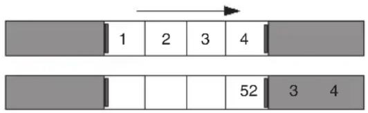
Example of a one-frame slip to the right. The head and tail frames of the segment change by one frame. The material before and after the segment remains fixed.
- In slide trimming, the two outer monitors for the outgoing (A-side) and incoming (B-side) frames change because the clip remains fixed while the footage before and after it is trimmed.

Example of a one-frame slide to the right. The segment does not change, but the material before the segment is trimmed out by one frame and the material after the segment is trimmed back by one frame.
Once you select the clips for slipping or sliding, the trim display changes to a four-frame display.

Four-frame display for slip and slide trimming. Left to right: outgoing video at position indicator, head and tail frames of the selected clip, incoming video at position indicator.
Selecting Segments for Slip or Slide Trimming
To select segments for slip or slide trimming by dragging a lasso:
- In Source/Record mode, select a segment for slipping or sliding.
- Drag a lasso from right to left around a segment (two or more transitions).
Your Avid editing application enters slip trim by default.
- To switch to slide trim, press and hold the Shift+Alt keys (Windows) or Option key (Macintosh) while dragging the lasso from right to left.
To select segments on a lower track:
- Press and hold the Alt key (Windows) or Option key (Macintosh) while dragging a lasso around the segment.
- To switch to slide trim, press the Alt key (Windows) or Option key (Macintosh) and double-click the segment.
You can also select two or more contiguous segments within a track for slipping or sliding by dragging the lasso around four or more transitions.

Be sure to drag the lasso from right to left. If you drag from left to right, you select the segment, not the transition.
To select segments for slip or slide trimming:
- Position the mouse pointer over one of the transitions for the segment you want to trim so the pointer changes to a trim icon, and double-click the transition to select the segment for slip trimming.
- To select a segment for slide trimming, double-click the transition.
To select two or more segments on different tracks for simultaneous slip or slide trimming, do one of the following:
▶Press Shift and select the head and tail of a segment for slipping.
Press Shift and select the outgoing tail frame of the preceding segment and the incoming head frame of the following segment in a sequence for sliding.
Performing a Slip or Slide Trim
To slip or slide a shot:
- After selecting the segments, as described in “Selecting Segments for Slip or Slide Trimming” on page 754, do one of the following:
▶ Click any roller in the Timeline, drag the selected material to the left or right, and release the mouse button.
▶ Use the numeric keypad to enter specific frame-count or timecode values, and press Enter.
▶ Use the trim keys or buttons to shift the selection by 1-frame or 10-frame (8-frame for 24p) increments.
▶Use the J-K-L keys.
- Monitor the progress of the trim by using the monitors, the Trim counters, and the Timeline.
When you reach the end of available material while slipping a shot, the trim stops. Similarly, when you reach the next transition while sliding a shot along a track, the trim stops. A red bracket at the transition indicates the limit. After completing the initial slide, you can perform another slide in the same direction.
- When you finish, exit Slip mode or Slide mode by doing one of the following:
▶Click another transition for trimming.
Click either the Source/Record Mode or the Effect Mode button.
▶Click the Trim Mode button on the Tool palette.
▶Press the Escape key.
To slip a shot in Source/Record mode:
- Select the tracks for the clips to be slipped.
- Move the position indicator within the shot that you want to slip.
- Slip the shot by doing one of the following:

Click the Slip Left button to slip the shot one frame left (revealing later material from the source clip).

Click the Slip Right button to slip the shot one frame right (revealing earlier material from the source clip).
Alt+click (Windows) or Option+click (Macintosh) the Slip Left or Slip Right button to trim 10 frames (8 frames for 24p) at a time.
The Slip Left and Slip Right buttons do not appear on the interface by default. You must map them from the Trim tab in the Command palette to use this procedure.
Trimming in Two Directions
You can select non-contiguous transitions in the Timeline and perform a trim simultaneously on all selected transitions. This allows you to trim segments without altering the duration of the sequence in cases where you cannot perform a simple dual-roller trim. For example, if you need to trim the outgoing frames of one segment, but you do not want to trim the incoming frames of the segment at the same transition, you can select another edit point to use in the trim.
| Seagull | school of fish0 | low angl | |
| Seagull | school of fish | low angl | |
| Seagull | school of fish | low angl | |
| ) | dts_44k_diatonis_cloudless.wav | ||
| 01:00:05:00 01:00:10:00 | |||
You can also trim in two directions by trimming frames from one segment while adding frames to a second segment. This can help to keep video and audio aligned when you do not have the alternative of using a dual-roller trim or sync locked tracks.
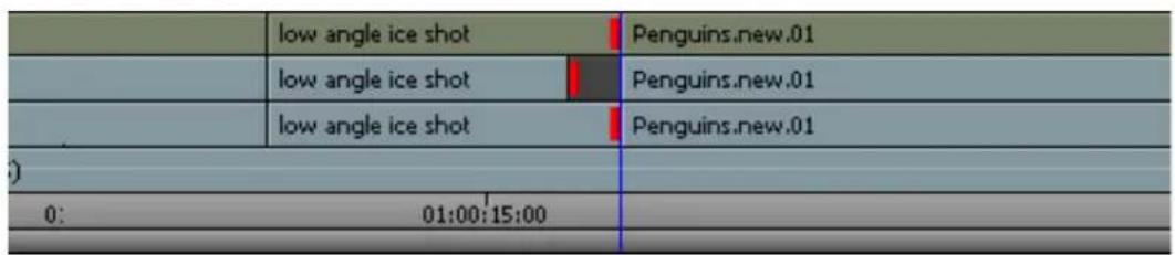
To trim in two directions:
- Select one or both of the trim tools on the Timeline palette, and then click the outgoing (A-side) or incoming (B-side) monitor to define which side of the transition to trim.
The pointer changes to an overwrite trim or a ripple trim icon over either the A-side or the B-side of the transition, depending on the position of the pointer. - Shift+click the other transitions in the Timeline you want to trim.
- Click and drag in the direction you want to trim.
Using the Transition Corner Display
The Transition Corner Display is a trim editing interface that shows six frames you can use as reference points when trimming a transition effect.

Transition Corner display. Left: the two frames on which the transition effect starts. Center: the two frames between which the cut point defines the transition. Right: the two frames on which the transition effect ends.
Use the Transition Corner Display to trim the transition effect's start frames, end frames, and duration in timecode or feet+frames (for 24p and 25p projects). As you trim the transition effect, you can see the corresponding frame adjustments in all six monitors simultaneously.

The Transition Corner Display applies only to the trimming of transition effects (for example, dissolves, wipes, picture-in-picture, and so on). It is not designed for trimming key, image, or segment effects.

The Transition Corner Display feature is only available when you use Big Trim display. To ensure that you use Big Trim display when you make a trim, select "Never use Small Trim mode" in the Features tab of the Trim Settings dialog box. For more information, see "Trim Settings: Features Tab" on page 1441.
To trim a transition using the Transition Corner Display:
- Select a transition effect for trimming by doing one of the following:

▶ Position the mouse pointer over the transition you want to trim so the pointer changes to a dual-roller icon, and click the transition.
▶Lasso the effect in the Timeline from right to left.
Click the Trim Mode button, and click in the transition in the Timeline, or use the Go to Edit buttons to step through transitions until you highlight the transition you want.
For more information, see “Dual-Roller Trimming” on page 744.


- Click the Transition Corner Display button.
The button changes to green, and the display is enabled.

To use this button, you must display two rows of buttons in the Composer window or map the button to a palette or a keyboard key. For more information, see “The Command Palette” on page 110.
- Trim the transition effect by clicking the outgoing or incoming frame you want to trim, and then position your pointer on the rollers and drag the transition backward or forward. Press and hold the Alt key (Windows) or Option key (Macintosh) to roll forward or backward slowly one frame at a time.

- To review your edit, click the Play Loop button.
18 Working with Audio
You edit audio by using many of the same techniques and tools you use to edit video. Your Avid editing application also provides several unique features that facilitate audio editing, such as audio scrub, waveform displays, and tools for adjusting and mixing audio levels and pan between speakers as well as the frequency ranges of segments.
Basic audio editing is described in the following topics:
• Overview of Audio Tools
• Working with Multichannel Audio Tracks
- Displaying Track Formats in Bins
• The Track Control Panel
- Using Audio Scrub
• Audio Displays in the Timeline
- Displaying Audio Formats in Bins
• Working with Surround Sound Audio
- Adjusting the Play Buffer Size for Audio (Software-only Models)
• Using the Audio Mixer Tool
- Rendering and Unrendering Order for Audio Effects
• Audio Volume Staging and an Audio Editing Workflow
• Using Clip Volume and Pan Mode
• Using Volume and Pan Automation
• Copying, Pasting and Moving Audio Keyframes
• Using Live Mix Mode
• Fading and Dipping Audio
- Adjusting Audio Clip Gain in the Timeline
• Audio Sample Rate Conversion
- Changing the Audio Sample Rate for Sequences and Audio Clips
- Mixing Down Audio Tracks
- Splitting Multichannel Tracks to Mono Tracks
• Using the Audio EQ Tool
• Recording Voice-Over Narration
Overview of Audio Tools
The following table describes the general purpose of each audio tool in your Avid editing application:
Audio tool Description
| Audio Mixer tool This tool adjusts pan and volume levels on clips or whole tracks within a sequence. For more information, see “Using the Audio Mixer Tool” on page 788. | |
| Audio EQ tool This tool adjusts the sound characteristics of audio clips in the sequence based on three-band control over high, low, and midrange frequencies. For more information, see “Using the Audio EQ Tool” on page 838. | |
| Avid AudioSuite Plug-In tool | This tool accesses third-party audio plug-ins. For more information, see “Avid AudioSuite Plug-Ins” on page 925. |
| RTAS tool This tool inserts Real-Time AudioSuite (RTAS) track effects on selected tracks. For more information, see “Real-Time AudioSuite Plug-Ins” on page 918. | |
| Audio tool This tool adjusts and calibrates global input and output levels when capturing from analog sources or output to tape. For more information, see “Understanding the Audio Tool” on page 203 and “Preparing for Audio Output” on page 1053. | |
| Audio Punch-In tool This tool records up to two or four channels of audio (depending on the model of your Avid editing application) directly into the Timeline for voice-over narration. For more information, see “Recording Voice-Over Narration Using Audio Punch-in” on page 853. | |
Accessing Audio Effect Tools
The following audio effect tools can display in a single tabbed window or in separate windows:
• A u d i o M i x e r
- AudioSuite
• A u d i o E Q
You can arrange these tools in a single, tabbed tool window to make it easy to switch to another tool.
To access one of the audio effect tools:
▶ Select Tools > tool name.
To keep more than one tool open at the same time:
▶ Select Tools > tool name, and then drag the tool to a tabbed tool window.
To prevent confusion, your Avid editing application allows only one copy of an audio effect tool to be open at a time. For example, you can open only one copy of the Audio EQ tool.
Using Audio Timecode
Your Avid editing application can read audio timecode (LTC, or longitudinal timecode, recorded on an audio track). If you captured the LTC as an audio track, use the Read Audio Timecode command. This command instructs your Avid editing application to access this track for timecode information to be displayed in the bins and used in editing.
To use timecode on an audio track:
- In the bin, select the appropriate clips.
- Select Special > Read Audio Timecode.
The Read Audio Timecode dialog box opens.

- Select User Bit Timecode to read timecode stored in the user bits of the LTC.
If you do not select this option, the system reads the LTC timecode.

Information contained in the user bits of the LTC must be timecode only. Other data stored in the user bits does not appear in your Avid editing application.
-
Click the Audio Timecode Source menu, and select the audio track containing the timecode. A1 is the default.
-
Click the Destination Track menu, and select the target auxiliary timecode bin column for recording the audio timecode.
Auxiliary TC1 is the default selection.
- Do one of the following:
▶ Select Fill Undecodeable Frames to instruct the system to fill in any timecode breaks with continuing timecode. This is the default.
▶ Deselect Fill Undecodeable Frames if you do not want to fill timecode breaks.
For example, in a 3-minute master clip, the audio timecode starts at 1:00:20:20. At 1:00:22:10, the timecode ends. With the Fill Undecodeable Frames option selected, the system assigns 1:00:22:11 to the next frame and continues assigning timecode.
- Click OK to complete the procedure.
The timecode appears in the bin in the auxiliary timecode column that you selected.
Working with Multichannel Audio Tracks
Video and audio information in your project can be represented as tracks, channels, and voices. The following list defines these terms as used in this documentation:
- Track s
- A region of a clip or sequence on which audio or video is placed.
- A playback channel represented in a sequence as either a video track or an audio track. You edit tracks in the Timeline.
- Channels
- A physical audio input or output. You capture audio channels, which then become audio tracks in your clip or sequence.
- The separate audio signals that compose an audio track. Stereo tracks have two audio channels. 7.1 surround sound tracks have 8 channels.
• V o i c e s
- Discrete audio streams that you send from audio tracks to physical audio outputs, such as speakers or output channels. Typically, any audio channel for a track in your sequence uses a single voice. A mono audio clip uses one voice, a stereo clip uses two voices, and
a 5.1 or 7.1 surround sound clip uses six or eight voices. You can monitor up to 64 voices with your Avid editing application — for example, 16 mono tracks, 8 stereo tracks, or two 7.1 surround sound tracks.
You can edit multichannel audio tracks in the same way you edit mono audio tracks. Your Avid editing application supports the following audio track formats:
• M o n o
• S t e r e o
• 5.1 surround sound
• 7.1 surround sound
The Track Formats column in the bin Text view displays the format for all multichannel audio tracks in a master clip. You can modify the audio format by grouping or ungrouping selected audio tracks. You can modify audio formats for master clips only. Track formats for sequences, group clips, or subclips cannot be modified.
For more information on surround sound multichannel audio, see “Working with Surround Sound Audio” on page 779.
Displaying Track Formats in Bins
You can select a bin heading to display the track formats in the bin. Multichannel formats appear in the Track Formats column for master clips and list the audio tracks in the clip that combine multiple channels in a single audio track. For example, a track format marked as “Stereo A1A2” indicates that the clip includes a stereo track with two channels.
To add the Track Formats column to a bin:
- With a bin in Text view, select Bin > Choose Column.
The Bin Column Selection dialog box opens. - Click Track Formats in the list to select it.
- Click OK.
The Track Formats column appears in the bin.
Modifying Track Formats in Bins
You use the Modify command to set or change the multichannel formats for your audio tracks. For example, this lets you create a stereo track from two associated mono tracks or to split a stereo track into two separate audio tracks. You can set the multichannel format for multiple master clips at the same time.
If you duplicate a clip in a bin and modify the track format in the copy, you can create a sequence that contains both a multichannel and a mono instance of the same master clip. This does not cause a problem with editing, playback, or any other operation.
You can also split multichannel tracks in the Timeline into mono tracks. for more information, see “Splitting Multichannel Tracks to Mono Tracks” on page 837.
To set the multichannel audio format for audio tracks:
- Open the bin and click the Text tab.
- Click the icon to the left of the clip you want to modify. Ctrl+click (Windows) or Cmd+click (Macintosh) each additional object you want to modify.
- Do one of the following:
▶Select Clip > Modify.
▶Right-click a clip and select Modify.
The Modify dialog box opens.
- Click the Modify Options menu, and select Set Multichannel Audio.
The Modify dialog box displays the audio tracks for all selected clips with format buttons beneath paired tracks. If an audio track is not used by the selected clips, it does not appear.


Track formats for sequences, group clips, or subclips cannot be modified.
- Do one of the following:
▶Click the Format buttons to cycle through the available options until you find the appropriate format.
▶Click the Format menu on a Format button and select the appropriate multichannel format.
Option Description

Mixed tracks Does not modify the audio track formats. The Mixed
Format Tracks button appears only when you select more than one clip and the clips contain both mono and multichannel tracks.
Mono tracks Sets the paired audio tracks to two mono tracks.
Stereo tracks Sets the paired audio tracks to one stereo track.

5.1 Surround Sets the selected tracks to one 5.1 surround sound track.
sound tracks

Sets the selected tracks to one 7.1 surround sound track.
7.1 Surround sound tracks
6. Click OK.
The bin information updates to reflect the audio format modifications. Check the Track Formats column in bin Text view to see all multichannel audio tracks.
The Track Control Panel
Timeline tracks include a Track Control panel that provides features useful when you edit audio tracks. The Track Control panel arranges components in two rows of tools, and it allows you to do the following when editing either a sequence or source material displayed in the Timeline:
- Show or hide waveforms, volume, and pan displays on individual tracks or on all tracks (see “Displaying Audio Waveforms” on page 773 and “Displaying Volume and Pan Values” on page 775).
- Add, delete, move, and copy RTAS ^ (Real-Time AudioSuite) effects (see “Real-Time AudioSuite Plug-Ins” on page 918).
• Mark tracks as inactive or solo or mute tracks so you can monitor the audio on a track.

Track Control panel
Component Description
Waveform Turns on or off the waveform display for individual tracks.
Clip Volume/Pan Turns on or off the clip volume and pan display for audio tracks.
Inactive Disables a track so you can play back your sequence without processing the plug-in effects or automation for the inactive track.
Solo Allows you to monitor a single track of audio without deselecting other tracks.
RTAS plug-ins Lists the RTAS plug-ins inserted on the track. Clicking the button for an existing RTAS insert opens the RTAS plug-in window so you can edit the plug-in parameters. Clicking a blank RTAS button opens the RTAS tool so you can insert a plug-in on the track.
Mute Allows you to mute a single track of audio without deselecting it.
Using the Track Control Panel
The Track Control panel displays two rows of tools. If you reduce the size of the Timeline tracks, you might not see the Track Control panel tools. For more information on resizing Timeline tracks, see “Enlarging and Reducing Timeline Tracks” on page 672.”
To show the Track Control panel, do one of the following:
Click the Timeline fast menu and select Track Control Panel. To hide the Track Control panel, deselect Track Control Panel.
▶Click the Track Control Panel button above the Timeline.

Track Control panel, with the Track Control Panel button above the Timeline
Soloing Audio Tracks
You can solo multiple tracks in the Timeline, which lets you do the following:
- Listen to several tracks at once without deactivating or deselecting the other audio tracks off or reducing volume.
- Isolate audio tracks for audio scrubbing without having to deselect monitoring of all other audio tracks.
For more information about audio scrubbing, see "Using Audio Scrub" on page 768.

You can also use the Track Solo buttons in the Audio Mixer tool. See “Using the Track Solo and Track Mute Buttons” on page 793.
To solo an audio track:

▶Click the Solo button in the Track Control panel for the track you want to solo.
The Solo button turns green, and Mute buttons on all other audio tracks turn orange.
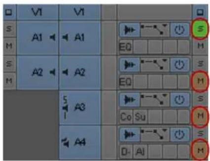
Solo button (green) and Mute buttons (orange) in the Track Control panel
To turn off soloing for the track:
▶Click the Solo button again.
To turn off the solo feature for all audio tracks:
Alt+click (Windows) or Option+click (Macintosh) the Solo button on any track.
Making Tracks Inactive
Unlike muted audio tracks, inactive audio tracks process no plug-in effects or automation. You can make any audio track inactive if you want to play back your sequence without audio information. This allows you to limit the number of voices you monitor so you can manage output voices as you play your sequence.
The Active/Inactive button displays the monitoring status of the track:
Icon State Description
| Primary active track — Audio information in these tracks is not dropped when the play speed increases during scrubbing. | |
| Active track — Audio information in these tracks might be dropped when the play speed increases during scrubbing, depending on your settings and track effects. | |
| Inactive track — Voices and audio plug-ins are not processed for these tracks during playback. |
To make an audio track inactive, do the following:
▶Deselect the Active/Inactive button in the Track Control panel.
You can click the Active/Inactive button again to restore audio monitoring to the track.
Using Audio Scrub
You have two options for scrubbing audio in either the sequence or the source material:
- Smooth audio scrub — Mimics the variable pitch playback of traditional analog tape
- Digital audio scrub — Takes advantage of the digital environment by sampling incoming frames, outgoing frames, or both at a normal pitch and playback rate
Digital audio scrub enables you to sample selected frames of incoming or outgoing audio as you move through the footage, without a change in pitch or speed. Digital scrub has the following unique characteristics:
- The frames of audio you hear are always at your point of destination. For example, if you step forward 10 frames (8 frames for 24p), you hear a selected number of audio frames from a point behind the position indicator (outgoing frames) to a point in front of the position indicator (incoming frames) as it reaches the new destination point.
- Digital scrub samples audio in a forward playback direction. Whether you step backward or forward through the material, you hear the same audio sampling at each destination frame.
Each type of scrub has its advantages:
- Smooth scrub makes it easier to examine sound at varying speeds.
- Digital scrub lets you focus quickly on individual bits of incoming or outgoing audio for frame-accurate edits and adjustments.

If you attach a 002 to Avid input/output hardware, you cannot hear the results of audio scrubbing.
Selecting Tracks for Audio Scrubbing
By default, all monitored audio tracks are selected for scrubbing. However, as the play speed increases during audio scrubbing, some monitored audio tracks are dropped. You can select up to two tracks to ensure they play during scrubbing, even if the system has to drop some tracks.
The following table shows how many tracks you can scrub at the varying speeds of play.
When you play footage forward or backward at: You can scrub:
Normal speed 16 tracks
Two times normal speed 16 tracks
Three times normal speed 2 tracks
Greater than three times normal speed 0 tracks
To ensure an audio track is monitored during scrubbing:

▶ Enable the Active/Inactive button in the Track Control panel for the selected track.

Active/Inactive buttons, displaying a black border to indicate tracks that can play without dropping audio information
The Active/Inactive button displays a black border to indicate which tracks can be played if the system has to drop tracks during audio scrubbing. By default, the two top Active/Inactive buttons display black border.
You can isolate specific audio tracks for scrubbing without having to deselect monitoring of all other audio tracks by soloing the audio tracks. See “Soloing Audio Tracks” on page 767.
To make a track the primary active track:
Alt+click the Audio Track Monitor button for the selected track.
Performing Smooth Audio Scrub
You can use three-button play with the J-K-L keys to perform smooth audio scrubbing of selected tracks of audio at variable speeds but not digital audio scrub. You can monitor while stepping (jogging) or while shuttling at fixed rates up to three times normal speed. The audio cuts out at greater than three times the normal speed and comes back in after the speed drops below three times.
(Symphony) You can also use the mouse to perform smooth audio scrubbing of selected tracks. Mouse Jog lets you move the position indicator with the mouse. Mouse Shuttle lets you control the speed of the position indicator by dragging the mouse. You can jog and shuttle using the mouse but, unlike three-button play, playback rates using the mouse do not occur at fixed increments. They can vary all the way from 1 to 300 fps, depending on manipulation of the mouse.
To monitor audio with three-button play:
- Select the correct track, and adjust the playback volume as necessary.
- Play the audio by using the three-button variable speed playback procedures described in "Playing Footage with the J-K-L Keys (Three-Button Play)" on page 512.
(Symphony) To monitor audio with the mouse:
- Select the correct track, and adjust the playback volume as necessary.
- Activate the mouse for jogging or shuttling by pressing the Mouse Jog button or the Mouse Shuttle button.


Both buttons are available in the Play tab of the Command palette and can be mapped to an editing button under the Record monitor.
To deactivate jog or shuttle, press the space bar or the Escape key.
- Play the footage with the mouse.
Adjusting Digital Scrub Parameters
The default parameters for the number of frames you hear as you scrub are zero frames of outgoing audio (behind the position indicator) and one frame of incoming audio (ahead of the position indicator). To isolate frames for marking or trimming, the default parameters are sufficient.
You can increase these settings to include more frames of audio on either side — for example, when you want to sample whole words or parts of words as you scrub to find edit points within a phrase. You can also reverse the settings to sample frames behind the position indicator
(outgoing frames) as you scrub. You should avoid increasing the number of sampled frames on both sides at once because this can make it difficult to isolate an edit point or trim point based on the location of the position indicator.
To adjust the parameters for digital scrub:
- Double-click Audio in the Settings list in the Project window.
The Audio Settings dialog box opens.


The Play Buffer Size in Samples option and the Tool Buffer Size in Samples option appear only if your Avid editing application is not using Avid input/output hardware (software-only).
- Click in a text box and type a new number of outgoing or incoming frames on the source side, the record side, or both.
The new parameters take effect.
Performing Digital Audio Scrub
To locate an audio edit point by using digital scrub:
- Solo an audio track for scrubbing and adjust the output volume, if necessary.
- Press the Caps Lock key to activate digital audio scrub.
You can also activate digital audio scrub by pressing and holding the Shift key while you drag the position indicator or click the Step buttons as described in step 3.
- Move through the material in one of the following ways to hear the scrub:
▶Drag the position indicator.
Click the Step buttons to step through in fixed increments: 1 frame backward, 1 frame forward, 10 frames (8 frames for 24p) backward, or 10 frames (8 frames for 24p) forward.
Step Buttons. Left to right, top to bottom: 1 frame backward, 1 frame forward, 10 frames (8 frames for 24p) backward, or 10 frames (8 frames for 24p) forward
- When you find the correct frame, mark the location, trim the transition, or perform any other function you choose.
When you sample incoming frames (with the default scrub parameters, for example), the system places the position indicator at the head of the last sampled audio point. When you sample outgoing frames, the system places the position indicator at the tail of the last sampled audio point.
Audio Displays in the Timeline
You can display audio waveforms in the Timeline to help you visually locate points in an audio track for editing or trimming. Waveforms for multichannel tracks in the Timeline display waveforms for all channels within a single track, separated by a horizontal divider. For more information, see “Displaying Audio Waveforms” on page 773.
You can also view a graph for pan and volume information in the Timeline. For more information, see “Displaying Volume and Pan Values” on page 775.
If you have a sequence with several different sample rates, you can identify a specific sample rate by color. For more information, see “Identifying Sample Rates by Color” on page 776.
The following notes apply to audio displays:
- When you click a Waveform or Clip Volume/Pan button in the Track Control panel, or when you Alt+click (Windows) or Option+click (Macintosh) a Waveform or Clip Volume/Pan button to display all waveforms or pan displays, the Avid editing application maintains the display setting with the sequence. You cannot save specific per track settings in a custom Timeline view.
- You can map the Allow Per Track Settings menu command on the Timeline fast menu to the keyboard. This provides you a quick method of turning selected track waveform displays off and on as you edit. For example, if you display waveforms for audio tracks A1 and A2 but not A3 and A4, and then disable per track settings, no waveforms display in the Timeline. When you enable per track settings, only A1 and A2 display waveforms. You can save the menu command state in a custom Timeline view.

The Avid editing application stores per track settings with the sequence and does not apply them to other sequences. Timeline views are saved as user settings, so you can apply them to any of your sequences.
Displaying Audio Waveforms
Audio waveforms in the Timeline display a sample plot of the entire amplitude of the track. This is the same as the sample voltage values seen on an analog oscilloscope waveform. You can display waveform plots for all audio tracks in the Timeline or you can select individual tracks for waveform display.
The editing application saves cached waveforms for projects. This allows the waveform to draw faster the next time you open the project. You will see a WaveformCache folder in the Avid Projects directory. The WaveformCache folder also appears in the Shared Avid Projects directory.
You might want to display waveforms on only some of your audio tracks. To do this, you can activate per track settings, or you can create a custom Timeline view as described in "Customizing Timeline Views" on page 668.
You can also select Show Marked Waveforms in the Timeline Settings dialog box to narrow the view of the tracks in the Timeline. This option allows the Timeline to display faster because the waveform displays only between the Mark In and the Mark Out points.
To display audio waveforms for all tracks:
-
To search for a point in a known section of the tracks, zoom in and show more detail in the sequence to isolate a section of the audio. With less audio to display, the system draws the waveform plot faster.
-
Do one of the following:

Click the Timeline fast menu and select Audio Data > Allow Per Track Settings, and then Alt+click (Windows) or Option+click (Macintosh) the Waveform button in the Track Control panel for any track.
▶ Click the Timeline Fast menu button, and select Audio Data > Waveform.
Press Ctrl+period (Windows) or Command+period (Macintosh) at any time during the redraw of the waveform plot to stop the redraw.
The waveform appears in all audio tracks.

- (Option) Maximize the visibility of your waveform display using one of the following procedures:
▶Continue to expand or shrink your view of the Timeline by using the scale bar, spreading out the waveform plots to show detailed variations in the audio levels.
To enlarge the height of selected audio tracks and subsequently the waveform display, press Ctrl+L (Windows) or Command+L (Macintosh).
To reduce the height of selected audio tracks and subsequently the waveform display, press Ctrl+K (Windows) or Command+K (Macintosh).
To enlarge the size of the waveform plot image without enlarging its track, press Ctrl+Alt+L (Windows) or Command+Option+L (Macintosh).
This procedure is useful when you view detail in loud passages.
To reduce the size of the sample plot image without reducing its track, press Ctrl+Alt+K (Windows) or Command+Option+K (Macintosh).
This procedure is useful when you view detail in quiet passages.
- Move through the audio shown in the waveform using any of the playback methods.
You hear sound as you track the audio visually. When the position indicator reaches the point you want in the waveform, you can mark, trim, or perform any other function.
To display audio waveforms for selected tracks:
- Click the Timeline fast menu and select Audio Data > Allow Per Track Settings.
- Click the Timeline fast menu and select Audio Data > Allow Per Track Settings, and then click the Waveform button in the Track Control panel for the tracks you want to display audio waveform plots.
The waveform appears in the selected tracks.


You can turn off all waveforms on selected tracks by disabling Allow Per Track Settings. This disables the display of waveforms, but it does not change the per track settings. Enabling per track settings again restores your per track waveform displays. You can also save the Allow Per Track Settings state as part of a customized Timeline view. For more information, see “Customizing Timeline Views” on page 668.
Displaying Volume and Pan Values
You can view the volume and pan automation values in the Timeline, including surround sound pan values for sequences using a surround sound mix. If you choose to view volume and pan on individual tracks rather than on the entire sequence, you can view volume values on one track and pan values on another.
When you display pan information in surround sound sequences, you can select which speaker layout you want to view. For example, if you want to view the pan information for a stereo track in a 5.1 surround sound sequence, you can view how either the left or right stereo channel pans in the following speaker configurations:
- Front speaker position
- Front speaker position
- Front and rear speaker positions
- Center speaker position, displayed as a percentage

For information on displaying audio waveform information and using per track settings, see "Displaying Audio Waveforms" on page 773.
To turn on the display of clip volume values and volume automation values for all tracks, do the following:

Alt+click (Windows) or Option+click (Macintosh) the Clip Volume/Pan button in the Track Control panel for any track, and select Clip Volume or Volume.
To turn on the display of clip volume values and volume automation values for selected tracks, do the following:

Click the Clip Volume/Pan button in the Track Control panel for the tracks you want to display clip or volume automation information, and select Clip Volume or Volume.
The volume values appear in the selected tracks.
▶ (Option) If you want to view both clip volume and volume values, repeat the previous step and select an additional volume value to display.
To turn on the display of pan values in the Timeline:

- If you want to view pan values for all tracks, Alt+click (Windows) or Option+click (Macintosh) the Clip Volume/Pan button in the Track Control panel and select one of the pan value options (pan value options depend on the sequence format and track format in your project):
▶Pan
▶Pan L > [speaker layout]
▶Pan R > [speaker layout]

- If you want to view pan values for individual tracks, click the Clip Volume/Pan button in the Track Control panel for the tracks you want to display pan information, and select the appropriate pan option:
▶Pan
▶Pan L > [speaker layout]
▶Pan R > [speaker layout]
The pan values appear in the selected tracks.
Identifying Sample Rates by Color
To apply a color coding to a sample rate:
- Load a sequence with multiple sample rates into the Timeline.
- Do one of the following:
To display waveforms for all tracks, click the Timeline Fast Menu button, and select Audio Data > Waveform.
To display waveforms for a single track, click the Waveform button in the Track Control panel.
- In the Project window, double-click Audio Project.
The Audio Project Settings dialog box opens.
- Click the Main tab.
- Click the Convert Sample Rates When Playing menu, and select Always.
- Click the Show Mismatched Sample Rates as Different Color menu, and select Yes.
Depending on which sample rate you selected for your project, the color black is displayed on those clips. For example, if you selected 48 kHz from the Sample Rate menu in the Main tab in the Audio Project Settings dialog box, the sample plot of these clips (48 kHz) is displayed as black, and the sample plot of all other clips with different sample rates (32 kHz and 44.1 kHz) is displayed as white.

Example of mismatched sample rates displaying with different colors in the Timeline. Clips with a 48 kHz sample rate display as black, while clips with other sample rates display as white.
Using Audio Meters in the Timeline
The Audio meters in the Timeline let you view and adjust audio levels without opening the Audio tool.
The Meter menu options are the same options as those available in the Audio tool. For more information, see “Understanding the Audio Tool” on page 203.
To display the Audio meters in the Timeline:

▶Click the Meter Menu button, and select Show Audio Meters.
The Audio meters display in the Timeline.

Audio meters display in the Timeline. Left to right: Master Volume button, Tracks indicators, In/Out Toggle buttons, Meter menu button
When you load a sequence in the Timeline and press the Play button, the Audio meter displays the audio levels of the audio tracks in your sequence.


When the Audio meter is hidden, extra mappable buttons are available. For more information on mapping buttons, see “Mapping User-Selectable Buttons” on page 112.
Adjusting Volume
You can adjust your speaker or headphone volume without leaving your Avid editing application.
You can also mute audio in several ways:
• Using the Master Volume button in the Timeline
- Using the Mute button in the Play tab of the Command palette
The Mute button lets you quickly make all audio tracks inactive or active during editing.
This is convenient when you fine-tune complex audio and video edits, making it possible to shift quickly between the two. You can set your audio levels and speaker volumes and mute them whenever necessary without changing the settings.
- Using the Mute buttons in the Audio Mixer tool to mute selected tracks
For more information, see “Using the Track Solo and Track Mute Buttons” on page 793.
- Using the Mute button in the Track Control panel.
For more information, see “Soloing Audio Tracks” on page 767.
(Windows) To adjust the volume control (software-only models):
- From the Timeline, click and hold the Master Volume button.

Master Volume button (left) and Audio Meter menu button (right) in the Timeline
If you do not see the Master Volume button, click the Audio Meter menu button, and then select Show Audio Meters. The Master Volume button displays with the Audio Meters.
The Windows Mixer appears.
- On the Windows Mixer, drag the volume control to the audio level you prefer.
(Macintosh) To adjust the volume control (software-only models):
- From the Timeline, click and hold the Master Volume button.

Master Volume button (left) and Audio Meter menu button (right) in the Timeline
If you do not see the Master Volume button, click the Audio Meter menu button, and then select Show Audio Meters. The Master Volume button displays with the Audio Meters.
The Volume Control slider appears.
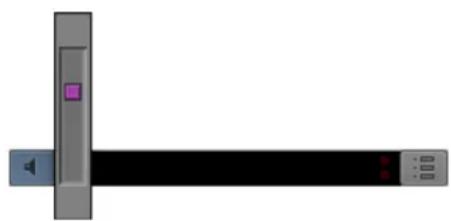
natural_image
Pure diagram of a computer monitor with left and right sides, no text or symbols present-
Continue to click and hold, and drag the volume control to the audio level you prefer.
-
Release the mouse button.
To adjust the volume control (models using Avid input/output hardware):
Adjust the volume control on your Avid input/output hardware to the desired audio level.

Adjusting the volume control affects the volume only while you work in your Avid editing application. Once you exit your Avid editing application, the volume control defaults to your desktop setting.
To mute volume from the Timeline:
▶Click the Master Volume button.
A line appears through the button, and you cannot hear audio through your speakers or headphone. The Mute buttons on individual tracks do not change when you use the Master Volume button to mute audio.

This does not apply to software-only models using Windows Vista and later.
To mute an individual audio track:

Click the Mute button in the Track Control panel for the track you want to mute.
To mute all audio tracks:

▶Ctrl+click (Windows) or Command+click (Macintosh) the Mute button on any track.
To turn the volume for audio tracks back on:

▶Click the Mute button to deselect it.
Displaying Audio Formats in Bins
You can select a bin heading to display the audio formats in the bin. The applicable audio format, AIFF-C, WAVE, PCM, or SDII (Macintosh), appears in the Audio Format column for master clips.
To add the Audio Format column to a bin:
- With a bin in Text view, select Bin > Choose Columns.
The Bin Column Selection dialog box opens. - Click Audio Format in the list to select it.
- Click OK.
The Audio Format column appears in the bin.
Working with Surround Sound Audio
Avid editing applications let you edit audio in mono and multichannel formats, including surround sound audio. You can hear this audio as either mixdown multichannel audio or as true stereo and surround sound using two, six, or eight speakers.
Six-channel and eight-channel digital surround sound systems use several different 5.1 and 7.1 speaker formats that constitute a standard in major motion pictures, music, and digital television. Speaker layouts generally use left and right speakers, left rear and right rear surround speakers, left side and right side surround speakers, center speaker, and a low frequency effects (LFE) speaker. The following table summarizes the supported multichannel formats and standard speaker configurations.
Mixing Format Surround Format Speaker Layout
Stereo Left, Right
5.1 Film Left, Center, Right, Left surround rear, Right surround rear, LFE
5.1 SMPTE Left, Right, Center, LFE, Left surround rear, Right surround rear
7.1 Pro Tools Left, Center, Right, Left surround side, Right surround side, Left surround rear, Right surround rear, LFE
7.1 SMPTE Left, Right, Center, LFE, Left surround side, Right surround side, Left surround rear, Right surround rear

The 5.1 Film format is the default surround sound format for monitoring 5.1 surround sound audio and 7.1 Pro Tools is the default surround sound format for monitoring 7.1 surround sound audio.
The following illustrations show sample surround sound speaker arrangements (5.1 and 7.1 SMPTE surround sound formats).

5.1 SMPTE surround sound configuration, with left (L), center (C), right (R), left surround rear (Lsr), right surround rear (Rsr), and low frequency effects (LFE) speakers

7.1 SMPTE surround sound configuration, with left (L), center (C), right (R), left surround side (Lss), right surround side (Rss), left surround rear (Lsr), right surround rear (Rsr), and low frequency effects (LFE) speakers
The Output tab in the Audio Project Settings dialog box lets you select which surround sound option you want to use when you export a sequence with surround sound audio. You can also use the Output tab to select the 5.1 or 7.1 option to designate a project with surround sound audio even if you do not have surround tracks in your sequence. If you have more than six or eight tracks, or if the tracks are given in a different order, you can use the Direct Out channel map to designate which tracks of the sequence go to which channels.

The Direct Out channel map affects the audio on the desktop monitors and the output. When you use direct out to export a clip or to play a clip in the Source monitor, the channel order reflects the channel order used when you captured the audio. You might need to reset the channels prior to a Digital Cut to preserve a required channel order on the output tape.
When you select a surround sound format, the Avid editing application displays the appropriate pan tools to use when you edit your sequence. Setting the surround sound format determines in which format you can mix your audio. For example, if you want to mix your audio in 5.1 surround sound, you need to assign that format to your sequence.
To assign a surround sound sequence format:
- Select Tools > Audio Mixer.
The Audio Mixer tool opens.
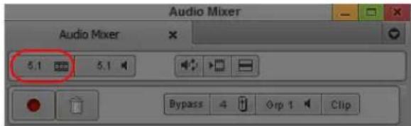
Audio Mixer tool: Sequence Format button
- Click the Sequence Format button and select one of the following:
▶Stereo Sequence
▶5.1 Sequence
▶7.1 Sequence
Channel meters in the Audio Mix tool default to the Film format (for 5.1 sequences) or Pro Tools (for 7.1 sequences). Channel meters in the Audio tool reflect the monitor mix format.
Surround Mixing
Your Avid editing application allows you to mix in surround sound and create output in different formats. You can also mix down your surround sound sequences to mono, stereo, or different surround sound formats.
Surround sound audio tracks contain an individual channel for each signal in the track (for example, a 5.1 track has six channels, one each for left, center, right, left surround, right surround, and LFE). You can add surround sound master clips to your project in different ways:
- You can capture the audio from your source (see “Selecting Source Tracks and Audio Channels” on page 189).
- You can import the audio using standard import procedures (see “Importing with Multichannel Audio” on page 289).
- You can modify existing audio clips to create surround sound audio (see “Working with Multichannel Audio Tracks” on page 762).
Stereo and multichannel tracks consist of multiple audio signals, linked together. The Audio Mixer tool displays a channel faders for each multichannel track, in addition to solo and mute buttons. If you need discrete control of signals, you can convert multichannel tracks to individual mono tracks (see “Splitting Multichannel Tracks to Mono Tracks” on page 837).
You can mix mono, stereo, and surround sound audio tracks in any supported multichannel format. The Audio Mixer tool indicates the track format by the number of track meters contained in its fader strip (for example, a single meter for mono tracks, a pair of meters for stereo tracks, and six meters for 5.1 tracks). Assigning track output determines the format of that output. For example, a mono track always has a single track meter, even when assigned to a stereo output path. If you assign a mono track to a 5.1 output path, the output splits among six output channels, depending on the position of the panner.
Surround Monitoring
In order to monitor your multichannel mix, you must have appropriate hardware connected to your computer — for example, an audio card that supports surround sound or a Nitris DX connected to your system. You also need to set up the proper speaker placement and calibrate your audio system for the surround sound format of your sequence. When your audio system does not match your surround sound mix — for example, if your workspace includes only stereo speakers while your sequence uses a 5.1 Film format — you need to understand how your Avid editing application delivers surround sound tracks to the available output channels.
When your monitoring setup does not support the audio format selected for a sequence, your Avid editing application downmixes the audio tracks to the desired monitor mix. The following table describes the speaker arrangements of mono, stereo, and surround mix formats and the corresponding monitoring structure. Sequence format indicates which format you select for your sequence, and speaker layout describes how the Avid editing application outputs audio tracks to a mono speaker, two stereo speakers, and six and eight surround sound speakers. Speaker placement, alignment, and calibration depend on your specific hardware and audio configuration. See the documentation that came with your speakers and other monitoring equipment.
Sequence format Speaker Layout
Mono Mono: Audio channels panned to center
Stereo Mono: L and R channels panned to center
Stereo: L and R channels panned to Left/Right
5.1 Mono: All channels panned to center
Stereo: C and LFE channels panned to center; L and R channels panned to Left/Right; Lr and Rr channels panned to Left/Right and volume lowered by 3dB
5.1: All channels panned to the appropriate speakers, depending on 5.1 format of the sequence
7.1: C, L, R, Lsr, Rsr, and LFE channels panned to appropriate speakers; Lss and Rss channels are not used
7.1 Mono: All channels panned to center
Stereo: C and LFE channels panned to center; L and R channels panned to Left/Right; Lsr, Rsr, Lss, and Rss channels panned to Left/Right and volume lowered by 3dB
5.1: C, L, R, Lsr, Rsr, and LFE channels panned to appropriate speakers; Lss and Rss channels panned to center of the Left/Left Rear and Right/Right Rear speaker pair
7.1: All channels panned to the appropriate speakers
For example, if your sequence uses the 5.1 Film surround sound format, but your studio has two stereo speakers, the Avid editing application mixes down your six audio tracks to the following monitoring layout:

flowchart
graph TD
    A["L"] --> B["C"]
    C["R"] --> D["(-3 dB)"]
    E["Lsr Rsr"] --> F["(-3 dB)"]
    G["LFE"] --> H["(-3 dB)"]
    I["L"] --> J["C"]
    K["R"] --> L["(-3 dB)"]
    style A fill:#000,stroke:#000
    style C fill:#000,stroke:#000
    style E fill:#000,stroke:#000
    style G fill:#000,stroke:#000
    style I fill:#000,stroke:#000
    style K fill:#000,stroke:#000
Top: 5.1 Film sequence format; bottom: stereo speaker layout, with center pan indicated by the double arrow
In addition to monitoring your audio through your speakers, you can monitor surround sound audio as it plays by watching the channel faders in the Audio Mix tool and in the Audio tool. When playing a sequence in the Timeline, the Audio Mix tool matches the default 5.1 Film surround sound format or the default 7.1 Pro Tools format. The channel faders in the Audio tool match the format of the sequence mix (see “Assigning Surround Sound Mix Output” on page 784).
Assigning Surround Sound Mix Output
You can set a surround sound mix output for any sequence in your project. This specifies how the Avid editing application sends surround sound signals to your speakers and determines what you hear when you monitor the audio in your sequence.
Your monitor mix output might differ from your sequence format. If you want to mix your audio in a surround sound format but only have two stereo speakers connected to your system, you can set your sequence format to surround sound and your mix output to stereo. If you need to mix your sequence in stereo but you have configured your speakers for surround sound output, you can set your sequence format to stereo and your mix output to surround sound. This ensures that the Avid editing applications sends the correct signals of your stereo channels to your surround sound speaker system.
To designate a surround sound mix output:
- Select Tools > Audio Mixer.
The Audio Mixer tool opens.
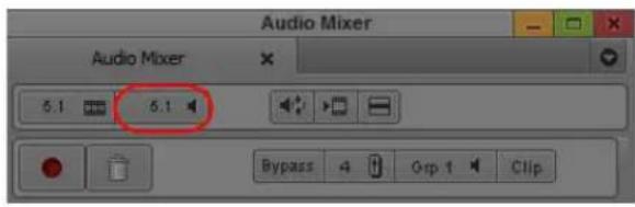
Audio Mixer tool: Monitor Mix Format button
2. Click the Monitor Mix Format button and select one of the following:
▶5.1 Film: L C R Ls Rs Lfe
▶5.1 SMPTE: L R C Lfe Ls Rs
▶7.1 Pro Tools: L C R Lss Rss Lsr Rsr Lfe
▶7.1 SMPTE: L R C Lfe Lsr Rsr Lss Rss
When you play a clip in the Source monitor, the monitor mix respects the channel order used when you captured the audio.
Setting Up the Analog Audio Output for Surround Sound Audio (Avid Nitris DX and Avid Mojo DX Only)
Depending on the Avid input/output hardware attached to your system, you can have two balanced TRS audio outputs labeled Monitor and four balanced XLR audio outputs labeled Analog. The TRS outputs are always left and right speakers. You can configure the XLR outputs in the Output tab of the Audio Project Settings dialog box.
If your workflow requires analog output to a tape deck, you configure the XLR outputs to connect to a deck. You see these channels, 1 through 4, in the Direct Out Channel Menu map in the Output tab of the Audio Project Settings dialog box.
If your workflow does not require analog output to a tape deck, you can use the XLR outputs to provide Center, LFE, Left Rear and Right Rear channels for desktop monitoring.
When the analog output is marked for use as desktop surround monitors, you should set the audio connectors as shown in the following table.
| Channel | Speaker |
TRS Channel 1 Left Front
TRS Channel 2 Right Front
XLR Channel 1 Center
XLR Channel 2 LFE
| Channel | Speaker |
| XLR Channel 3 Left Rear | |
| XLR Channel 4 Right Rear | |
To set up for an analog audio output:
- Double-click Audio Project in the Settings tab of the Project window.
The Audio Project Settings window opens. - Click the Output tab.
- Click the Analog tab.
- Depending on your setup, select Use as Output to Tape Deck or Use as Desktop Surround Monitors.
- Click the Mix Mode Selection Menu button to select Direct Out.
- If necessary, assign the tracks and channels through the Direct Out channel menu.

If the sequence in the Timeline is multichannel or is direct out without being surround sound audio, the four analog XLR outputs remain silent and only the left and right speakers are active.
Setting Up the Audio Output with HDMI (Avid Nitris DX and Avid Mojo DX Only)
Avid supports two ways to configure your audio output, either 2-channel stereo speaker setup or 6-channel surround sound setup. To achieve the 6-channel surround sound setup, connect your audio output through an High-Definition Multimedia Interface (HDMI) connection.
HDMI carries both video and audio in an uncompressed, all-digital signal. HDMI is an interface standard for audiovisual equipment such as high-definition television.
In order to use HDMI for audio, the HDMI device attached to your system must receive at least two channels of PCM (uncompressed) audio at the project sample rate and receive 6 channels or more of PCM audio.
If you send the HDMI output to a deck, the deck receives the channels in the Timeline in the same order as the channels set in the Direct Out Channel map in the Audio Project Settings window. If you configure your system for surround sound audio, the output is sent in the HDMI standard channel order as shown in the following table.
| Channel | Speaker | |||
| 1 | L | e | f | t |
| 2 | R | i | g | h |
| 3 LFE or Subwoofer | ||||
| 4 | C | e | n | t |
| 5 Left Rear | ||||
| 6 Right Rear |
To set up for a surround sound (HDMI) audio output:
- Double-click Audio Project in the Settings tab of the Project window.
The Audio Project Settings window opens. - Click the Output tab.
- Click Direct Out, then select First six tracks are 5.1 surround: L, R, C, LFE, LR, RR.
- Click the HDMI tab.
- Depending on your setup, select Use as Output to Tape Deck or Use as Desktop Surround Monitors.
When you select Use as Output to Tape Deck, LFE and Center are swapped from the recommended track order.

If your HDMI device cannot play six channels of audio or if the 5.1 option in the Direct Out tab is not selected, the option to Use as Desktop Stereo Monitors does not appear.
-
Click the Mix Mode Selection Menu button to select Direct Out.
-
If necessary, assign the tracks and channels through the Direct Out channel menu.
Adjusting the Play Buffer Size for Audio (Software-only Models)
You can use third-party host audio devices, such as a Sound Blaster ^® audio card, in software-only configurations of Avid editing applications. Although most host audio devices work properly within Avid editing applications, some exhibit problems during output (for example, audio clicking). You might also encounter audio latency issues when adding audio effects such as volume automation. To counteract these problems, use the Play Buffer Size in Samples slider and the Tool Buffer Size in Samples slider in the Audio Settings window.
Avid strongly recommends that you use the default “recommended sample” setting, which is determined by the host audio device connected to your system.
For more information on the Buffer Size in Samples sliders, see “Audio Settings” on page 1353.
To adjust the samples in the play buffer or tools buffer:
- Double-click Audio in the Settings tab of the Project window.
The Audio Settings window opens.
- In the Play Buffer Size in Samples, click and drag the slider to select a sample size.
- In the Tool Buffer Size in Samples, click and drag the slider to select a sample size.
If you change the default setting, a warning dialog box opens informing you of how this change might affect your system.
- Click Change.
- To select the Avid recommended default setting, click the rs (recommended sample) button.
Using the Audio Mixer Tool
The Audio Mixer tool has three modes that let you perform the following tasks:
Mode Task Description
| Clip Volume and Pan | Lets you adjust the overall volume and pan values for a clip, in a bin or in the Timeline.For more information, see “Using Clip Volume and Pan Mode” on page 797. |
| Volume automation and Pan | Lets you adjust and record volume and pan changes within a clip in the Timeline.For more information, see “Using Volume and Pan Automation” on page 813. |
| Live Mix Lets you temporarily override any existing volume and pan automation settings. You can use the controls on the Audio Mixer tool or use an external controller to change volume and pan settings without modifying the existing volume and pan automation settings.For more information, see “Using Live Mix Mode” on page 825. | |
Accessing the Audio Mixer and Audio Mixer Modes
To open the Audio Mixer tool, do one of the following:
If one of the Audio tools is already open, click the Effect Mode Selector menu, and select Audio Mixer.
▶Select Tools > Audio Mixer.
The Audio Mixer tool opens.
To select the Audio Mixer mode, do one of the following:
▶Click and hold the Audio Mixer mode button, and select the mode from the menu.
▶ Click the Audio Mixer mode button and cycle through the Audio Mixer mode settings to the mode you want to select.
Audio Mixer Tool Controls
The following illustrations and tables identify the controls of the Audio Mixer tool in Clip Volume and Pan mode, including controls common to all three modes. The elements described in the following tables appear in all Audio Mixer modes unless otherwise noted. For specific information on Volume and Pan Automation mode, see “Using Volume and Pan Automation” on page 813. For specific information on Live Mix mode, see “Using Live Mix Mode” on page 825.

Top part of Audio Mixer tool
Element Description
1 Sequence Mix
Format button
Lets you select the sequence mix format.
Element Description (Continued)
2 Monitor Mix button Controls how your system interprets audio values during playback:
- Stereo: Mixes the currently monitored audio tracks into a stereo pair. Depending on your Avid input/output hardware, you can customize the mix using the Stereo Mix Tracks option.
- Mono: Pans all the currently monitored tracks to center and ignores pan effects.
- 5.1 as L C R Lr Rr Lfe: Mixes currently monitored tracks to the appropriate surround sound channel. See “Surround Monitoring” on page 782.
- 5.1 as L R C Lfe Lr Rr: Mixes currently monitored tracks to the appropriate surround sound channel. See “Surround Monitoring” on page 782.
- 7.1 as L C R Lss Rss Lr Rr Lfe: Mixes currently monitored tracks to the appropriate surround sound channel. See “Surround Monitoring” on page 782.
- 7.1 as L R C Lfe Lr Rr Lss Rss: Mixes currently monitored tracks to the appropriate surround sound channel. See “Surround Monitoring” on page 782.
- Direct (available depending on your Avid input/output hardware): Maps tracks directly to the available output channels. Ignores pan settings. On Symphony systems, by default, Direct Out maps the first eight audio tracks in numerical sequence to the first eight output channels. You can remap a track to any channel by clicking the Channel Assignment menu and selecting another channel.
3 Audio Loop Play button Lets you adjust audio effects while looping over a portion of audio. This button is also available in the Play tab of the Command palette. For more information, see “Adjusting Volume While Playing a Clip Volume Effect” on page 809.
4 Render Effect button Lets you render audio effects. For example, if you change the level of a clip that contains a rendered audio dissolve, the effect becomes unrendered. You can use the Render Effect button to rerender the audio dissolve directly from the Audio Mixer tool. Then you can play back the clip immediately to hear the effect of the level change with the dissolve in place.
5 Fast Menu button Lets you select from a list of functions that vary according to the Audio Mixer mode. For more information, see the following topics:
- “Audio Mixer Fast Menu: Clip Volume and Pan Mode” on page 808
• “Audio Mixer Tool Fast Menu: Volume and Pan Automation Mode” on page 819
• “Audio Mixer Tool Fast Menu: Live Mix Mode” on page 827
6 Bypass button Lets you temporarily turn off any Clip Volume or volume automation effects. This button functions the same as the Bypass panel in the Effects tab in the Audio Project Settings dialog box. (This control does not appear in Live Mix mode.)
7 Number of Mix Panes Lets you display four or eight panes. For more information, see “Resizing the Audio Mixer Tool” on page 792.
Element Description (Continued)
| 8 Display/Hide Sliders button | Lets you switch between hiding and displaying the Volume Level sliders. |
| 9 Which Set of Tracks to Display in Mix Panes buttons | Lets you select which enabled tracks to display in the mix panes. When you display 8 panes (with the Number of Mix Panes button), Grp 1 displays tracks 1-8. Click the Which Set of Tracks to Display in Mix Panes button to change it to Grp 2, which displays tracks 9-16. When you display 4 panes, each click of the Which Set of Tracks to Display in the Mix Panes button displays the next group of 4 tracks. |
| 10 Audio Mixer mode button | Lets you select the mode for the Audio Mixer tool:• Auto (volume and pan automation)• Clip (Clip Volume and Pan)• Live (Live Mix)The default mode is Clip Volume and Pan. The mode that you select is saved as a project setting. If you want to change the default mode, select the mode you want in the Audio Mixer tool, then save the Audio Project settings as a site setting. See “Using Site Settings” on page 1347.You cannot save Live Mix mode as a project setting. |

Bottom part of Audio Mixer tool
Element Description
| 1 Pan value and knobs Displays the pan value and lets you adjust it. These controls appear only when you select a surround sound format using the Sequence Mix Format menu or when you set Stereo, 5.1 Surround, or 7.1 Surround as output in the Audio Project settings. | |
| 2 Track Solo and Track Mute buttons | Lets you solo or mute selected tracks. The values persist when you switch to another group, switch to another Audio Mixer mode, and when you close the Audio Mixer tool. For more information, see “Using the Track Solo and Track Mute Buttons” on page 793. |
| 3 Volume Level sliders Lets you adjust the volume level of the clip. | |
| 4 Volume Level Displays | Displays the volume level of the track. You can click and type in a new value. In Clip Volume mode, if the track has an volume and pan automation value associated with it, the word Auto appears. In Volume and Pan Automation mode, if the track has a system clip volume value associated with it, the word Clip appears. |
| 5 Position Indicator Lights | Indicates whether the external fader controller or mixer is connected and configured correctly. For more information, see “Interpreting Position Indicator Lights” on page 794. |
| 6 Track Selection Menu buttons | Lets you enable tracks for mixing audio. When you select an item from this menu, the system selects or deselects the corresponding track in the Timeline. |
| 7 Group buttons Lets you group adjustments across tracks and have two or more sliders move at the same time. | |
| 8 Stereo Link For stereo sequences, links the two pan controls so that when you move one Pan Location cursor, the other moves in a parallel direction. | |
| 9 Stereo Mirror For stereo sequences, links the two pan controls so that when you move one Pan Location cursor, the other moves in a mirrored direction — for example, if you drag the Pan Location cursor to the left, the corresponding cursor in the second X/Y grid moves to the right. | |
| 10 Mix Panes Displays controls for each audio track, including controls for modifying volume and pan. | |
Resizing the Audio Mixer Tool
You can change the number of mix panes that display in the Audio Mixer tool, or hide the volume level sliders altogether. Both of these customizations can reduce the amount of space that the Audio Mixer tool occupies. You can continue to adjust levels by typing values when the sliders are hidden.
To add or remove items such as faders, legends, effect buttons, and the solo and mute buttons:
- Right-click in the Audio Mixer tool and select Set Display Options.
The Mix Tool Display Options dialog opens - Select the items you want to appear in the Audio Mixer Tool.
- Click OK.
To switch between displaying four tracks and eight tracks:
▶Click the Number of Mix Panes button.
To show or hide the Volume Level sliders:
▶Click the Display/Hide Sliders button.
To adjust levels when the sliders are hidden, do one of the following:
▶ Select a track, and type level values by using the numeric keypad on the keyboard.
▶Type values into the Volume Level display.
Track Selection in the Audio Mixer Tool and in the Timeline
When you select a track in the Audio Mixer tool, your Avid editing application selects the corresponding track in the Timeline. Similarly, when you select an audio track in the Timeline, your Avid editing application selects the corresponding track in the Audio Mixer tool.
You can use the audio track buttons in the Tracks tab of the Command Palette to select tracks in the Audio Mixer tool. You can map these buttons to any mappable button location or to the keyboard. For more information, see “Mapping User-Selectable Buttons” on page 112.
A track needs to be monitored in the Timeline before you can work with it in the Audio Mixer tool.
Using the Track Solo and Track Mute Buttons

The Track Solo and Track Mute buttons let you mute and solo individual audio tracks in all three modes. The settings persist between modes and stay in effect when you close the Audio Mixer dialog box. When you solo or mute tracks in the Audio Mixer tool, the system solos or mutes the corresponding tracks in the Timeline.
You can also use the buttons above each fader on the external fader controller or mixer to solo or mute an individual audio track as follows:
- Some EUCON devices have solo and mute buttons above the fader. Additionally, some devices include an On key, which indicates that a specified track is unmuted.
- 002, Command|8 ^ and MCS-3000X have separate buttons for solo and mute. On Symphony systems, Command|8 ^ and MCS-3000X have separate buttons for solo and mute.
Interpreting Position Indicator Lights
The position indicator lights indicate whether the external fader controller or mixer is connected and configured correctly. They also provide information about the current location of the volume faders on the external fader controller or mixer.

Position indicator lights in the Audio Mixer tool
The following table describes how to interpret the position indicator lights.
Colors Description
Both lights are blue. The fader matches the current Timeline volume.
Only top light is blue. The fader is higher than the Timeline volume.
Only bottom light is blue. The fader is lower than the Timeline volume.
Both lights are gray.
Either there is no fader controller or mixer attached to the system or the Avid system does not recognize the fader controller or mixer.

The position indicator lights are not used for pan recording. However the blue lights do indicate that the device is connected and configured correctly.
The position indicator lights are especially useful for the FaderMaster Pro because you must position the faders close to the track volume before you start recording. Otherwise, you might create an unwanted jump in the volume when you move the faders during a recording.

Your Avid editing application does not record values from a fader on the FaderMaster Pro until you move the fader. Then it reads the current position of the fader and adjusts the volume accordingly. In many cases, it is not possible to exactly match the Timeline value.
You do not have to reposition the faders on the 002, MCS 3000X, Command|8, Yamaha 01V, and Yamaha 01V/96 because the units automatically reset the faders to match the volume data in the Timeline.
(Symphony) You do not have to reposition the faders on the MCS 3000X, Command|8, Yamaha 01V, and Yamaha 01V/96 because the units automatically reset the faders to match the volume data in the Timeline.
For more information on fader controllers or mixers, see “Using External Audio Devices” on page 858.
Rendering and Unrendering Order for Audio Effects
Your Avid editing application processes audio effects in the following order (you can also think of this as the audio volume staging):
- Clip Volume and Pan (Audio Mixer tool in Clip Volume mode — real-time).
- AudioSuite plug-ins (AudioSuite tool — non-real-time).
- EQ (Audio EQ tool — real-time, can be rendered).
- Audio Fade or Dissolve (Quick Dissolve button — real-time, can be rendered).
- Volume and pan automation (Audio Mixer tool in Volume and Pan Automation mode — real-time).
Changing an audio effect unrenders any audio effect that follows it in the render order but does not affect audio effects that precede it in the render order. For example, if you have a clip that contains clip volume, an AudioSuite plug-in effect, and volume automation, and you change the volume automation, the system does not unrender the AudioSuite plug-in effect. This preserves the workflow because you use volume automation for finishing the audio levels. You need to hear how changes in the volume automation affect the rendered effects. You could add, render, and modify EQ and audio dissolves on the same clip and you still would not unrender the AudioSuite plug-in effect.
However, if you change the clip volume on the same clip, the system unrenders the AudioSuite plug-in. This preserves the workflow because when you reset the level of the clip, you need to reprocess any effects applied to the clip.

If you have an AudioSuite plug-in and an Audio EQ effect applied to the same effect, only the Audio EQ effect icon displays. The AudioSuite plug-in still applies even though the icon is not visible.
Audio Volume Staging and an Audio Editing Workflow
You can adjust the volume of an audio clip at several points during an editing session. For example, you can adjust volume using the Audio Mixer tool in Clip Volume mode and Volume and Pan Automation mode. Also, the EQ tool and many of the AudioSuite and RTAS plug-in effects let you modify the volume of the clip. When you can adjust the volume in a signal chain at several points, the process is referred to as audio volume staging. This section describes the audio volume staging model used by Avid editing applications. It also describes a basic workflow for taking advantage of the volume staging.
You can set audio volume levels with the Audio Mixer tool. When you use the Audio Mixer tool in Clip Volume mode, values set by the volume level sliders are referred to as system clip volume values. When you use the Audio Mixer tool in Volume and Pan Automation mode, values set by the Audio Mixer tool are additive to the system clip volume values. This lets you adjust the values separately. You typically adjust clip volume values first, as in the following workflow:
- Adjust overall volume (Clip Volume).
- Apply effects (Audio Effect Processing).
- Fine-tune volume (volume automation).
This workflow lets you apply effects to an audio clip in a way similar to the signal flow in a mixing console.
In this workflow, clip volume is like a trim level, where you can lower (attenuate) or increase (amplify) the levels of a clip before applying any other effects. For example, when importing a sound file from an audio CD, you notice when the level of the clip is very high and close to clipping (distortion). If you add an EQ effect to raise the level of the bass, the audio starts to distort. To solve this problem, you can use clip volume to lower the signal level. Then you can adjust the bass in the EQ tool without distorting the audio.
The following workflow illustrates this procedure:
- Use the Audio Mixer tool in Clip Volume mode to lower the overall volume.
- Apply an EQ effect and any other audio effects.
- Use the Audio Mixer tool in Volume and Pan Automation mode to fine-tune the volume of different sections of the audio in the sequence.
This workflow also applies to using AudioSuite and RTAS plug-ins because some plug-ins affect the level of the audio. Often, if you use clip volume to raise or lower the level before you apply an audio effect, you can achieve higher quality results.
In this workflow, the Audio Mixer tool in Volume and Pan Automation mode acts like the level faders on a console for final mixing of the audio material.
For more information, see "Using the Audio Mixer Tool" on page 788.
Using Clip Volume and Pan Mode
The Audio Mixer tool in Clip Volume and Pan mode lets you do the following:
- Adjust volume and pan for an individual clip, a whole track, several tracks at once, or a whole sequence.
- Adjust the volume, pan, or both for one track at a time.
- Adjust the volume, pan, or both for multiple tracks simultaneously by grouping them together.
The system uses these adjustments for all playback, including output to a digital cut.

For additional information on audio levels for digital cut output, see “Preparing for Audio Output” on page 1053.
When the Audio Mixer tool is in Clip Volume and Pan mode, you can adjust the volume and pan values for entire clips only. You can use Volume and Pan Automation mode and Live Mix mode to adjust volume and pan levels within a clip in the Timeline. For more information, see “Using Volume and Pan Automation” on page 813 and “Using Live Mix Mode” on page 825.
The default volume for master clips is set to zero (that is, with no attenuation) when you first capture the media. For a description of how to integrate clip volume into your workflow, see “Audio Volume Staging and an Audio Editing Workflow” on page 796.
There are two basic ways to work with pan values:
- Create or modify an audio pan effect. This method creates an effect that is stored with the sequence, as described in “Adjusting Clip Volume and Pan for Audio Tracks” on page 798 and “Using the Center Pan Command” on page 812.
- Modify the way that your Avid editing application interprets pan values during playback, as described in “Modifying How Your Avid Editing Application Interprets Pan” on page 811.

You can create pan effects only when you select stereo or surround sound output (in the Output tab of the Audio Project Settings window).
Adjusting Clip Volume and Pan for Audio Tracks
To adjust clip volume and pan for audio tracks:
- Load a clip or sequence, and activate the appropriate monitor:

To adjust a track in a source clip, click the Source monitor to make it active.
To view a source clip's tracks in the Timeline, click the Toggle Source/Record in Timeline button.
▶ To adjust a track in a sequence, click the Record monitor to make it active.
- Select the track or portion of a track you want to adjust:
To adjust the track in a single edited clip in a sequence, place the position indicator in the clip.
To adjust an isolated section of audio on a track, mark In and Out points.
To adjust levels from an In point through the end of the track, mark an In point only. One mark also adjusts the entire track from the beginning of the clip that includes the mark.
▶To adjust levels globally throughout the track, make no marks.
- Select Tools > Audio Mixer.
The Audio Mixer tool opens.
- Select Clip Volume and Pan mode by doing one of the following:
Click and hold the Audio Mixer mode button, and select Clip Mode from the menu.
▶ Click the Audio Mixer mode button and cycle through the Audio Mixer mode settings to Clip.
- In the Audio Mixer tool, select the audio track to be adjusted by doing one of the following:
A1
▶ Click the Track Selection Menu button for the appropriate audio track.
Alt+click (Windows) or Option+click (Macintosh) the Track Selection Menu button, and then select a track.

To select more than one track, click the Group button for each track you want to group.

The Track Selection buttons in the Audio Mixer tool match the track selection buttons in the sequence or source clip. When you select a track in the Audio Mixer tool, the system selects the corresponding track in the Timeline or source clip. Selecting a track in the Timeline selects the corresponding track in the Audio Mixer tool.
To verify or change the output channels, use the Audio tool (select Tools > Audio Tool).
- With the Audio Mixer tool active, use any playback method (such as the J-K-L keys on the keyboard) to play, shuttle, or step through the audio to check for necessary volume or pan adjustments.
The keyboard can control either the Source or Record monitor, depending on which monitor was active when you opened the Audio Mixer tool. Switch your selection by clicking the appropriate monitor.
- Decide whether to raise or lower the volume. To change an audio level value in a mix pane, do one of the following:
▶Click a number along the vertical edge of the Level slider.
Click the Level slider, type a value, and press Enter (Windows) or Return (Macintosh).
Values are cumulative until you press Enter (Windows) or Return (Macintosh). For example, if you want to enter the value 12, type it. However, if you enter 1 and then want to change the value to 2, press Enter (Windows) or Return (Macintosh) before typing the 2.
- Click the Volume Level display, type a value, and press Enter (Windows) or Return (Macintosh).
- Click the Level slider, and then drag the slider to a new position.
- Alt+click (Windows) or Option+click (Macintosh) the Level slider to reset the value to 0 dB.

Top to bottom: Group, Stereo Link, and Stereo Mirror buttons; Pan controls and pan display; Audio Level sliders and meters; and Volume Level display in the Audio Mixer tool
- Decide if you want to adjust pan values. To adjust the pan values in a mix pane, do one of the following:
Click the Pan control, and then drag the control to a new position. Drag left or up to pan to the left, or drag right or down to pan to the right.

▶Alt+click (Windows) or Option+click (Macintosh) the Pan Value display for MID.
If you are working with a stereo sequence, two Pan controls appear in the Audio Mix tool for each track. Click the Pan control, and then drag the control to a new position. Drag left or up to pan to the left, or drag right or down to pan to the right.
(Option) If you are working with a stereo sequence, click the Stereo Link button if you want to link the two Pan controls so that when you move one control the other moves correspondingly. You can also click the Stereo Mirror button so that the two Pan controls mirror each other as you adjust them.
If you mix for a surround sound format, a multichannel Pan grid appears for each track. Click the panner icon and drag it to the desired pan position. For more information about surround panning, see "Using the Pan Grid for Surround Panning" on page 802.
If the sequence is playing, play stops when you make an adjustment.

You can adjust volume while playing the clip. For more information, see “Adjusting Volume While Playing a Clip Volume Effect” on page 809.

- Apply the adjustments to a chosen region of the track by using the Fast Menu button located in the top bar of the tool. See “Audio Mixer Fast Menu: Clip Volume and Pan Mode” on page 808.
- Play through the audio again, using the J-K-L keys.
- Repeat steps 7 through 10 until you are satisfied with the pan and volume levels.
Your Avid editing application stores the new settings and uses them whenever you play back or capture the sequence.
Surround Sound Pan Controls
When you work with surround sound sequences, you might need to pan tracks to the appropriate speakers. For example, if your surround sound sequence includes mono or stereo tracks, you might need to pan them to the left rear or right rear speaker positions. Your Avid editing application provides a multichannel Pan grid and an Advanced Panner which allow you to control audio panning.
- The Pan grid provides a simple control to pan your audio to any speaker position.
- The Advanced Panner provides a larger panning display and more controls to adjust the pan values for your sequence, including an X/Y grid, Position controls, and an LFE slider.
The following illustration shows the Pan grid and the Advanced Panner for mono tracks. Stereo tracks include a second Pan grid and Advanced Panner.
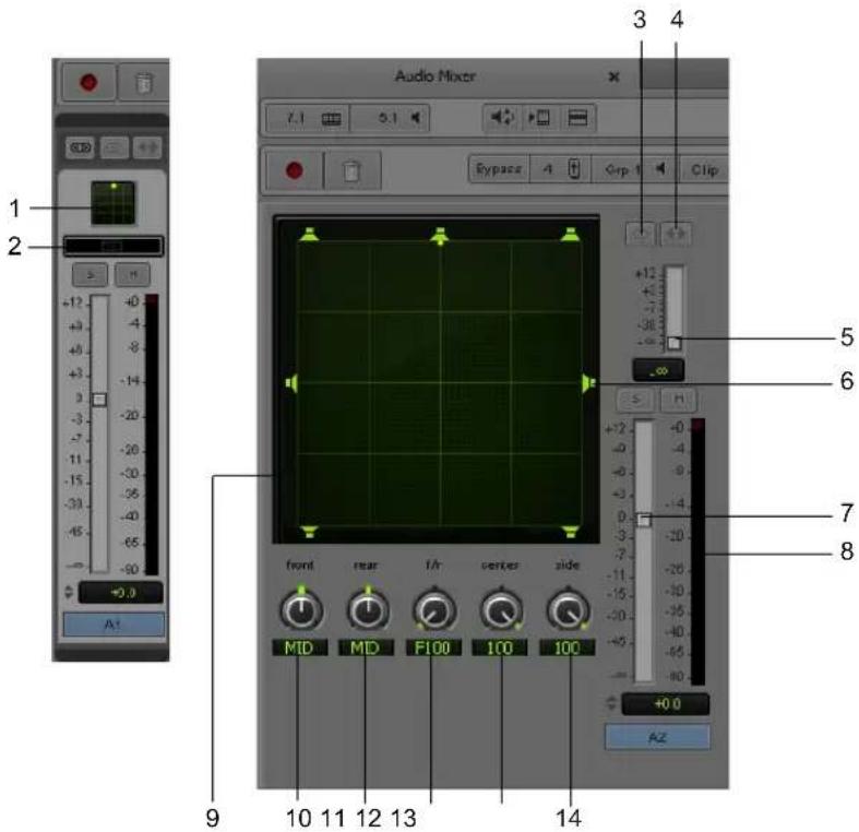
The following table describes the Pan grid and Advanced Panner controls:
Element Description
1 Pan Grid Allows you to input pan information by dragging the Pan Location cursor anywhere within the grid.
2 Advanced Panner button Opens the Advanced Panner.
3 Stereo Link button For stereo sequences, links the two pan controls so that when you move one Pan Location cursor, the other moves in a parallel direction.
4 Stereo Mirror button For stereo sequences, links the two pan controls so that when you move one Pan Location cursor, the other moves in a mirrored direction — for example, if you drag the Pan Location cursor to the left, the corresponding cursor in the second X/Y grid moves to the right.
| Element | Description | |
| 5 | LFE slider | Indicates the amount of the audio signal routed to the LFE channel. Scale is 0 - 100. |
| 6 | Speaker icon Allows you to snap the Pan Location cursor to the selected speaker. This pans the audio fully to that speaker position. | |
| 7 | Volume Level sliders Lets you adjust the volume level of the clip. | |
| 8 | Audio meter Displays the volume level for each channel in a track. | |
| 9 | X/Y Grid Allows you to input pan information by dragging the Pan Location cursor anywhere within the grid, by using 3-Knob mode, or by entering numeric values in the Position data fields. | |
| 10 | Front Position control Displays and controls the current front X-axis (left/right) position of the panner. | |
| 11 | Rear Position control | Displays and controls the current rear X-axis (left/right) position of the panner. |
| 12 | F/R (Front/Rear) Position control | Displays and controls the current Y-axis position of the panner. |
| 13 | Center percentage | Indicates the amount of the audio signal routed to the center channel. Scale is 0 - 100, with 100 sending the full signal to the center channel. |
| 14 | Side/Center percentage | For 7.1 surround sound sequences, indicates the amount of the audio signal routed to the right surround and the left surround speaker positions. Scale is 0 - 100. |
Using the Pan Grid for Surround Panning
The Pan grid displays for all mono and stereo tracks in a 5.1 or 7.1 multichannel sequence. The grid allows you to quickly adjust the pan for these tracks. For greater control over pan values, you can use the Advanced Panner (see “Using the Advanced Panner for Surround Sound Panning” on page 803.
To pan using the Pan grid:
- Select Tools > Audio Mixer.
The Audio Mixer tool opens.
- Select Clip Volume and Pan mode by doing one of the following:
Click and hold the Audio Mixer mode button, and select Auto Mode from the menu.
▶ Click the Audio Mixer mode button and cycle through the Audio Mixer mode settings to Auto.
- In the Audio Mixer tool, select the audio track to be adjusted by doing one of the following:
A1
▶Click the Track Selection button for the appropriate audio track.
Alt+click (Windows) or Option+click (Macintosh) the Track Selection button, and then select a track.
4. With the Audio Mixer tool active, use any playback method (such as the J-K-L keys on the keyboard) to play, shuttle, or step through the audio to check for necessary pan adjustments.
5. (Option) If you are working with a stereo track, click the Stereo Link button if you want to link the two Pan controls so that when you move one control the other moves correspondingly. You can also click the Stereo Mirror button so that the two Pan controls mirror each other as you adjust them.
6. Click the Pan Location cursor and drag it to adjust pan.
Using the Advanced Panner for Surround Sound Panning
The controls in the Advanced Panner provide different ways to pan mono and stereo tracks in your surround sound sequence:
- You can use the Pan Location cursor in the X/Y Grid to pan audio to any position in the surround sound mix.
- You can use the Position controls to pan in straight lines — moving the Pan Location cursor to the front, rear, and front-rear position — and to pan discretely between pairs of speakers.
For example, when panning left front to right rear with the Position controls, you hear audio from just those two speakers. By comparison, when panning in the X/Y Grid, a diagonal pan might result in audio being heard in some or all channels. The difference is that the Position controls pan discretely between the front and rear positions of the panning trajectory, while the X/Y Grid panning takes place in the full surround sound panning grid.
To pan using the X/Y Grid:
- Select Tools > Audio Mixer.
The Audio Mixer tool opens.
- Select Clip Volume and Pan mode by doing one of the following:
▶ Click and hold the Audio Mixer mode button, and select Auto Mode from the menu.
▶ Click the Audio Mixer mode button and cycle through the Audio Mixer mode settings to Auto.
- In the Audio Mixer tool, select the audio track to be adjusted by doing one of the following:
▶Click the Track Selection button for the appropriate audio track.
Alt+click (Windows) or Option+click (Macintosh) the Track Selection button, and then select a track.
A1
-
With the Audio Mixer tool active, use any playback method (such as the J-K-L keys on the keyboard) to play, shuttle, or step through the audio to check for necessary pan adjustments.
-
Click the Advanced Panner button.
The Advanced Panner opens.

-
(Option) If you are working with a stereo track, click the Stereo Link button if you want to link the two Pan controls so that when you move one control the other moves correspondingly. You can also click the Stereo Mirror button so that the two Pan controls mirror each other as you adjust them.
-
Drag the Pan Location cursor to pan the track. The location of the Pan Location cursor determines the pan position of the signal. For example, to pan something to the left rear speaker, move the Pan Location cursor to the lower-left corner of the grid.
You can snap the Pan Location cursor to one speaker position by double-clicking a speaker icon. This pans the audio fully to that speaker position. For example, if you click the upper left speaker icon, the Pan Location cursor moves to the upper left corner of the grid and pans the audio fully to the left speaker position.
Close
- When you finish adjusting pan with the Advanced Panner, click the Close button to return to the Audio Mixer tool.
To pan using the Position controls:
- Adjust the Front and Rear Position controls to set the trajectory line.
- Rotate the Front/Rear Position control to pan along the trajectory. The Pan Location cursor is constrained to the trajectory line.
- If you want to change the trajectory angles, do one of the following:
Drag either end point (Front or Rear) of the trajectory line.
▶Adjust the Front or Rear Position controls.
- If you want to change the current trajectory position (left-to-right) and retain its current angles, drag the trajectory line (not its end points) to a new position.
Using the Center Percentage and LFE Controls
The Advanced Panner provides you with additional controls:
- Center Percentage controls whether there is a discrete center channel for the track or a phantom center channel. For example, in film and video production, the center channel often contains dialog. To enhance the clarity of dialog, you might need to reduce the Center Percentage on music tracks, which forces music panned only to the left and right speakers and leaves a variable phantom center image.
- The LFE slider controls how much of the track is sent to LFE.
To adjust the Center Percentage:
- Select Tools > Audio Mixer.
The Audio Mixer tool opens.
- Select Clip Volume and Pan mode by doing one of the following:
Click and hold the Audio Mixer mode button, and select Auto Mode from the menu.
▶ Click the Audio Mixer mode button and cycle through the Audio Mixer mode settings to Auto.
- In the Audio Mixer tool, select the audio track to be adjusted by doing one of the following:
▶Click the Track Selection button for the appropriate audio track.
A1
Alt+click (Windows) or Option+click (Macintosh) the Track Selection button, and then select a track.
-
With the Audio Mixer tool active, use any playback method (such as the J-K-L keys on the keyboard) to play, shuttle, or step through the audio to check for necessary pan adjustments.
-
Click the Advanced Panner button.
The Advanced Panner opens.

-
Turn the Center Percentage control as needed.
-
When you finish adjusting the Center Percentage with the Advanced Panner, click the Close button to return to the Audio Mixer tool.
To adjust the LFE control:
- Select Tools > Audio Mixer.
The Audio Mixer tool opens.
- Select Clip Volume and Pan mode by doing one of the following:
Click and hold the Audio Mixer mode button, and select Auto Mode from the menu.
▶Click the Audio Mixer mode button and cycle through the Audio Mixer mode settings to Auto.
- In the Audio Mixer tool, select the audio track to be adjusted by doing one of the following:
▶Click the Track Selection button for the appropriate audio track.
Alt+click (Windows) or Option+click (Macintosh) the Track Selection button, and then select a track.
-
With the Audio Mixer tool active, use any playback method (such as the J-K-L keys on the keyboard) to play, shuttle, or step through the audio to check for necessary pan adjustments.
-
Click the Advanced Panner button.
The Advanced Panner opens.

- Adjust the LFE slider as needed.
Close
- When you finish adjusting the LFE with the Advanced Panner, click the Close button to return to the Audio Mixer tool.
Audio Mixer Fast Menu: Clip Volume and Pan Mode
The commands in the Audio Mixer tool Fast menu operate differently, depending on the types of points you set within the clip or sequence, as described in the following table:
Points Set Description
Both In and Out points Commands apply adjustments to selected tracks between the points.
In point only Commands apply adjustments to full clips from the In point to the end of selected tracks.
Out point only Commands apply adjustments to full clips from the beginning of selected tracks to the Out point.
None Commands apply globally (across entire tracks).
The following table describes the Audio Mixer tool Fast menu commands for Clip Volume and Pan mode:
Command Description
| Set Level on Track, Set Pan on Track | Applies the same pan or volume levels currently set in the Audio Mixer tool to all segments in the marked regions of the tracks. |
| Adjust Pan/Vols on Track | Opens a dialog box for making incremental adjustments to all current settings across segments in the marked regions of selected tracks.For example, when you type -1 in the Volume Adjustment text box, the various audio level settings across all segments of the marked region of selected tracks are lowered by exactly 1 dB when you click OK. |
| Remove Clip Volume on Track, Remove Pan on Track | Removes clip volume or pan values from the marked regions of selected tracks. |
| Remove Pan/Vols on Track | Deletes all audio mix adjustments that have been applied to segments in the marked regions of selected tracks. Each audio clip is restored to its default pan and volume settings. |
| Disable Track Monitoring | Makes an audio track inactive so that it does not process any audio information. |
Command Description
Set Display Options Opens a dialog that allows you to add or remove items such as the faders, legends, effect buttons, and the solo and mute buttons in order to save space in the Audio Mixer Tool.
Note the following:
- The commands in the Fast menu appear dimmed until you select a track.
- Levels set in master clips carry across to the sequence after you edit the clips.
- Clip volume values are the values for the entire segment; for example, you cannot set volume for a portion of a segment without affecting the entire segment. To set volume for a portion of a segment, use Volume and Pan Automation mode. For more information, see “Using Volume and Pan Automation” on page 813.
Bypassing Existing Volume Settings
You can instruct your Avid editing application to ignore the volume settings established with the Audio Mixer tool when playing back or recording a sequence.
To turn off current volume adjustments, do one of the following:
▶Click the Bypass button in the Audio Mixer tool.
Click the Clip Volume/Pan button in the Effects Bypass panel in the Effects tab of the Audio Project Settings window. See “Audio Project Settings: Effects Tab” on page 1359.
The volume controls disappear.
To restore the previous settings:
▶Click the Bypass button or the Clip Volume/Pan button again.
Adjusting Volume While Playing a Clip Volume Effect
You can use the Audio Loop Play button to change the volume on an existing Clip Volume effect while you play the clip. The Audio Loop Play button appears in several of the audio effect tools and is also a mappable button in the Play tab of the Command palette. For more information on mapping buttons, see “Mapping User-Selectable Buttons” on page 112.
While your Avid editing application plays the loop, you can do the following:
- Adjust audio effects.
• Use the Peak Hold menu in the Audio tool to change between Peak Hold and Infinite Hold. - Use the Reset Peak button in the Audio tool.
For more information on the Audio tool, see “Understanding the Audio Tool” on page 203. For information on improving response time, see “Improving Response Time When Adjusting Volume” on page 810.

For additional ways to change the volume while playing audio, see “Understanding Volume or Pan Automation Recording” on page 817.
To adjust volume while playing a Clip Volume effect:
- Do one of the following:
▶Select an existing Clip Volume effect.
▶Identify an area of the clip with In and Out points.
▶Place the position indicator over an audio clip.

- Click the Audio Loop Play button in the Audio Mixer tool.
Your Avid editing application repeatedly loops through the selected area as follows:
- If you have In and Out points on your sequence, the command loops over the selected area.
- If there are no In or Out points, the command loops over the shortest segment on the selected audio track at the position indicator.
-
If you have only an In point or only an Out point, the system uses the location of the position indicator as the second point. For example, if there is an In point and no Out point, the system loops from the In point to the end of the (smallest selected) audio segment under the position indicator.
-
Adjust the volume as necessary.
- Click the Audio Loop Play button to stop.
Your Avid editing application automatically saves your changes as part of a Clip Volume effect.
Improving Response Time When Adjusting Volume
If there is no Clip Volume effect on the clip before you start, you do not hear any changes until you click the Audio Loop Play button to stop and replay the effect.
As you adjust the volume values on an existing Clip Volume effect, you might not hear the results immediately. It takes a few seconds for your Avid editing application to apply the changes to the clip. The response time for this feature is considerably longer than it is when changing EQ parameters while using Audio Loop Play. You might need to click the Audio Loop Play button to complete the edit and then play the effect to hear the result.
You can also do any of the following:
- Monitor as few audio tracks as possible.
- Deselect the video track, if practical.
- Use In and Out points to select a narrow interval to adjust.
Modifying How Your Avid Editing Application Interprets Pan
The way you record footage in the field and capture it with your Avid editing application affects the way sound pans between the speakers. By default, the system pans mono audio tracks 1 and 3 to the left speaker output and pans mono tracks 2 and 4 to the right speaker output.
When you adjust pan values on multichannel stereo tracks, you pan the stereo mix of the left/right audio pair for the clip. For example, when you pan to the right output channel, you move the full stereo mix further to the right channel.
You can set global pan settings before or during editing by using the Audio Settings dialog box or the Audio Project Settings dialog box. You can also set pan for individual mono clips by using the Center Pan command.
To modify the way the system interprets pan during playback:
▶ Set the default pan values in the Audio Settings dialog box, which you access from the Settings list in the Project window.
By default, the mono audio tracks for clips alternate with track 1 on the left speaker and track 2 on the right speaker for monitoring and output. The All Tracks Centered option instructs the system to center the pan of all tracks between the two speakers for monitoring and output. The system pans stereo tracks to the center by default, with the left speaker panned full left and the right speaker panned full right.
Click the Mix Mode Selection Menu button in the Output tab in the Audio Project Settings window, and select one of the following modes (the options in the Mix Mode Selection menu depend on your audio hardware):
Mode Description
Stereo Uses the default pan settings and lets you create pan effects.
Mono Pans all mono tracks to center during output. This mode ignores pan effects.
Direct This mode uses the default pan settings and ignores pan/vol effects.
Using the Center Pan Command
You can use the Center Pan command on source material in bins. Use it prior to editing or at any time during the editing process.
Instead of adjusting pan on individual clips by using the Audio Mixer tool, Center Pan lets you create a standard distribution of audio between left and right speakers. You can adjust the pan on selected clips or all clips with a single command. This is especially useful when you have clips with field audio recorded (and subsequently captured) variably between A1 and A2. Panning all the audio to center eliminates the distraction of having to listen to left and right speakers, in turn. It also smooths the playback of the edited sequence because all shots are panned to center.
To adjust the pan on clips:
- In a bin, select the clips you want to pan to the center.
- Select Clip > Center Pan.
A dialog box opens and asks you to confirm the pan. - Click OK.
The system pans all the selected clips to the center.
Isolating Clip Portions for Audio Adjustment
When making audio level and pan adjustments, your Avid editing application looks at either an individual clip in the Source monitor, a segment in the sequence, or entire tracks. To change level or pan settings in an area not defined by a discrete clip or group of clips, use the Add Edit function to define your own custom area.
To isolate clip portions for adjustment:
- Find the start of the area where you want to change the pan or level, leaving your position indicator on that frame as a marker.
- Select the appropriate track in the Track Selector panel.
- Click the Add Edit button.
This places an edit where the position indicator is parked.
- Find the end of the area where you want to change the pan or level, leaving your position indicator on that frame as a marker.
- Select the appropriate track.
- Click the Add Edit button.
- Use the process described in “Using the Audio Mixer Tool” on page 788 to change the level or pan within this new segment.

Using Volume and Pan Automation
Volume and pan automation lets you change the volume or pan values of a segment by adding and manipulating volume or pan automation keyframes in the Timeline. The following illustration shows an expanded audio track containing volume keyframe information.

line
| X | Y | | --- | --- | | 0 | 0 | | 1 | -15 | | 2 | -45 | | 3 | -12 | | 4 | -18 | | 5 | -7 | | 6 | 0 | | 7 | -15 | | 8 | -45 | | 9 | -12 | | 10 | -18 | | 11 | -7 | | 12 | 0 |Example of the graphic representation of keyframes and volume ramps in the Timeline. Volume values in decibels are highlighted on the left.
Your Avid editing application uses a linear ramp to change the volume or pan from one keyframe to the next.
When you adjust pan parameters, you can select which parameter displays in the Timeline. The pan parameters available depend on your sequence format and the audio track format. The following table lists the volume and pan displays available in the Timeline:
Sequence Format Audio Track Format Volume and Pan Parameters
Stereo Mono None, Clip Volume, Volume, Pan
Stereo None, Clip Volume, Volume, Pan 1, Pan R
5.1 None, Clip Volume, Volume
7.1 None, Clip Volume, Volume
Surround Sound 5.1 Mono None, Clip Volume, Volume, Pan (Front, Rear,
FrontRear, Center %), LFE Volume
Stereo None, Clip Volume, Volume, Pan L (Front, Rear,
FrontRear, Center %), Pan R (Front, Rear, FrontRear, Center %), LFE Volume
5.1 None, Clip Volume, Volume
7.1 None, Clip Volume, Volume
Sequence Format Audio Track Format Volume and Pan Parameters
| Surround Sound 7.1 Mono None, Clip Volume, Volume, Pan (Front, Rear, FrontRear, Center %, Side Center %), LFE Volume |
| Stereo None, Clip Volume, Volume, Pan L (Front, Rear, FrontRear, Center %, Side Center %), Pan R (Front, Rear, FrontRear, Center %, Side Center %), LFE Volume |
5.1 None, Clip Volume, Volume
7.1 None, Clip Volume, Volume
You adjust volume and pan automation directly in the Timeline or by using the Audio Mixer tool.
Using Volume and Pan Automation in the Timeline
To use volume and pan automation to adjust volume or pan in the Timeline:
- Select an audio track for adjusting volume or pan.
- Click the Clip Volume/Pan button in the Track Control panel, and select the Volume or Pan option you want to adjust. Alt+Click the Clip Volume/Pan button to select all tracks. For more information on volume and pan options, see “Using Volume and Pan Automation” on page 813


If a clip contains volume automation or pan data and you do not select Volume or Pan from the Clip Volume/Pan menu, the system displays a pink triangle on the clip to indicate that automation data is present but not displayed.
You can enable Clip Volume, Volume, and Pan in the Clip Volume/Pan menu to display audio information superimposed over waveform plots in the Timeline. However, you cannot display Volume and Pan at the same time.
- (Option) Expand the audio track by doing one of the following:
▶Press and hold Ctrl+L (Windows) or Command+L (Macintosh).
▶ Press and hold the Ctrl key (Windows) or the Option key (Macintosh) while dragging in the Track Selector panel. When the pointer changes to a cross, drag the cross to expand or shrink the track.
If you expand the audio tracks enough, you can display volume data. The following illustration shows the expanded audio track with volume data.
bar
| Category | Value | |---|---| | a | 12 | | -45 | 45 | | -6 | 0 | | -9 | -9 | | -15 | -15 | | -45 | -45 | | a | 12 | | +6 | 16 | | 0 | 0 | | -2 | -2 | | -15 | -15 | | -45 | -45 |
- Click the Add Keyframe key on the keyboard ( ") or the Add Keyframe button on the Tool palette to add keyframes along the Timeline.
Your Avid editing application adds a keyframe to each enabled track. If you add a keyframe for pan, the keyframe applies only to the automation value displayed in the Timeline. For example, if you are working with pan left automation, the keyframe is added to the pan left automation values.
A straight line appears in the selected audio track. The line shows the current volume level for that track in the Audio Mixer tool.
After you add the first keyframe to a segment, you can adjust the volume for the entire clip. After you add a second keyframe, you can adjust the volume between keyframes.

line
| X | Series 1 | Series 2 | | ---- | -------- | -------- | | -45 | +12 | -12 | | -40 | +12 | -12 | | -35 | +12 | -12 | | -30 | +12 | -12 | | -25 | +12 | -12 | | -20 | +12 | -12 | | -15 | +12 | -12 | | -10 | +12 | -12 | | -5 | +12 | -12 | | 0 | +12 | -12 | | 5 | +12 | -12 | | 10 | +12 | -12 | | 15 | +12 | -12 | | 20 | +12 | -12 | | 25 | +12 | -12 | | 30 | +12 | -12 | | 35 | +12 | -12 | | 40 | +12 | -12 | | 45 | +12 | -12 |- Adjust the volume automation or pan keyframes by doing one of the following:
Click a keyframe and drag it up or down to increase or decrease the volume or pan at that point. If there is a point at the same position on another enabled track, it moves also. When you move the keyframe up or down, the corresponding Volume Level slider or Pan Value slider in the Audio Mixer tool also moves.
Click a keyframe and use the sliders, Pan controls, Position controls, or other controls in the Audio Mixer tool to adjust the volume or pan.
To snap to the decibel lines, press and hold the Ctrl key (Windows) or the Command key (Macintosh) while you drag the point.
▶ Move a keyframe horizontally to move the start or end of a ramp. Place the pointer over a keyframe. When the pointer changes to the hand pointer, press and hold the Alt key (Windows) or the Option key (Macintosh), click the keyframe, and drag it.
▶Move several keyframes vertically on a track at the same time by placing In and Out points to select the area you want. When you move one keyframe up or down within the marked area, all keyframes within the marked area move in relation to each other. This works for all enabled audio tracks.
This procedure is similar to grouping sliders on an audio mixing board or in the Audio Mixer tool.
To delete a single volume automation or pan keyframe:
- Move the pointer over the keyframe.
- When the pointer changes to the hand pointer, press the Delete key.

Don't press the mouse button. If you press the mouse button, you might change the volume.
If there are identical keyframes in other active tracks, your Avid editing application deletes them also.
To delete groups of volume automation or pan keyframes:
- Mark an In point and an Out point or mark the entire segment.
- Delete any keyframes in the marked area.
Volume and Pan Automation Mode
This topic describes controls in the Audio Mixer tool that are active only in Volume and Pan Automation mode.
In Volume and Pan Automation mode, record controls are available, as shown in the following illustration and described in the table. These controls are similar to those in the Audio Punch-In tool:
Left to right: Record button, Cancel button, and preroll and postroll text boxes in the Audio Mixer tool when in Volume and Pan Automation mode
Feature Description
Record button Starts and stops the recording.
Cancel button Stops a recording without saving the recorded data.
Preroll text box Lets you provide a visual cue before the recording begins. Your Avid editing application backs up the blue position indicator for the prescribed number of seconds.
Feature Description (Continued)
Postroll text box Lets you provide the same kind of visual cue at the end of the recording
The volume slider areas appear blue in Volume and Pan Automation mode.
For descriptions of other controls in the Audio Mixer tool, see “Audio Mixer Tool Controls” on page 789.
Understanding Volume or Pan Automation Recording
You can instruct your Avid editing application to record your actions while playing the clip as you move sliders to adjust volume or turn pan knobs to adjust pan values. Your Avid editing application creates the corresponding keyframes and saves them as part of a pan/volume audio effect. After you finish the recording, you can move, add, and delete keyframes to achieve the results you want.
You can do the following:
- Use sliders in the Audio Mixer tool to adjust volume values while you play the clip, as described in “Using the Audio Mixer Tool for Volume and Pan Automation” on page 817.
For additional information, see “Audio Mixer Tool Fast Menu: Volume and Pan Automation Mode” on page 819 and “Using Keyboard Shortcuts with Audio Keyframes” on page 820. - Use the stereo pan controls or surround sound controls to adjust pan values as you play the clip. For more information on using the multichannel pan controls, see “Surround Sound Pan Controls” on page 800.
- Attach an optional fader controller or mixer to the system, and use the faders on the unit to adjust volume.
- Attach an Avid Artist Mix or Avid Artist Control to the system, and use the pan knobs to adjust pan values for the active tracks.
For information about using an Avid Artist Mix or Avid Artist Control, see “Using Avid Artist Series Controllers” on page 890.
Using the Audio Mixer Tool for Volume and Pan Automation
You can record volume automation or pan information without using an external fader controller or mixer. You can also use command in the Audio Mixer tool Fast menu in Volume and Pan Automation mode for other tasks such as removing or incrementally adjusting volume automation or pan on a marked region. For more information, see “Audio Mixer Tool Fast Menu: Volume and Pan Automation Mode” on page 819.
To record volume automation or pan information by using the Audio Mixer tool sliders:
- Select Tools > Audio Mixer.
- Do one of the following:
Click and hold the Audio Mixer Mode button and select Auto Mode from the menu.
▶Click the Audio Mixer Mode button and cycle through the Audio Mix mode settings to the Auto mode setting.
-
Select an audio track for adjusting volume or pan.
-
Click the Clip Volume/Pan button in the Track Control panel and select the Volume or Pan option you want to adjust. Alt+Click the Clip Volume/Pan button to select all tracks.

If a clip contains volume automation or pan data and you do not select Volume or Pan from the Clip Volume/Pan menu, the system displays a pink triangle on the clip to indicate that automation data is present but not displayed.
- (Option) Expand the audio track by pressing Ctrl+L (Windows) or Command+L (Macintosh).
- Move the blue position indicator to the section of audio that you want to adjust and mark In to Out points.
- Click the Record button or press the B key to start recording your actions.
- Listen to the audio and do one of the following:
▶Adjust the Audio Level sliders in the Audio Mixer tool as necessary.
▶ Click the Pan Location cursor in the Pan grid in the Audio Mixer tool and adjust the position.
Click the Advanced Panner button in the Audio Mixer tool to open the Advanced Panner and adjust the pan controls. For more information, see “Using the Advanced Panner for Surround Sound Panning” on page 803.
- Click the Record button again to stop recording.
Your Avid editing application adds volume automation or pan keyframes to the audio in the Timeline. Because it records every movement of the sliders, there are usually more keyframes than you need.
- Decrease the number of keyframes:
a. Click the Track Selection Menu button for the track to enable the Fast menu.
b. Click the Audio Mixer Tool Fast Menu button, and select Filter volume automation on Track or Filter Pan on Track.
- Repeat step 10 until you have decreased the number of keyframes to an acceptable level.

You should remove as many excess keyframes as possible while still maintaining the volume changes.
You can move, add, and delete keyframes individually or as groups to further adjust the volume or pan. For details on how to adjust the keyframes, see “Using Volume and Pan Automation in the Timeline” on page 814.
Audio Mixer Tool Fast Menu: Volume and Pan Automation Mode
The commands in the Audio Mixer tool Fast menu operate differently, depending on the types of points you set within the clip or sequence, as described in the following table:
Points Set Description
Both In and Out points Commands apply adjustments to selected tracks between the points.
In point only Commands apply adjustments to full clips from the In point to the end of selected tracks.
Out point only Commands apply adjustments to full clips from the beginning of selected tracks to the Out point.
None Commands apply globally (across entire tracks).
The commands in the Fast menu appear inactive until you select a track.
The following table describes the Audio Mixer tool Fast menu commands for Volume and Pan Automation mode:
Command Description
| Filter volume automation on Track | Removes approximately 50 percent of the volume automation keyframes in the marked region. If you press and hold the Alt key (Windows) or the Option key (Macintosh) while selecting the menu item, the system removes all keyframes in the selected area, except for the minimum and maximum peaks. Your Avid editing application tries to save major gestures while removing redundant points and points on a linear ramp. This is useful for deleting extra keyframes after a recording. |
| Filter Pan on Track | Removes approximately 50 percent of the pan keyframes in the marked region. |
| Adjust Volume/Pan on Track | Opens a dialog box for making incremental adjustments to all current settings across segments in the marked regions of selected tracks. For example, if you type -1 in the Volume Adjustment text box, the various audio level settings across all segments of the marked region of selected tracks are lowered by exactly 1 dB when you click OK. |
| Remove volume automation on Track | Removes all of the volume automation keyframes within the marked region. |
| Remove Pan on Track | Removes all of the pan keyframes within the marked region. |
| Remove Volume/Pan on Track | Deletes all volume and pan automation adjustments applied to segments in the marked regions of selected tracks and restores each audio clip to its previous pan and volume settings. |
| Remove Hidden Volume Automation on Track - Global | Select this option to remove all the volume automation keyframes. |
| Remove Hidden Pan on Track - Global | Select this option to remove all the Pan keyframes. |
| Remove Hidden Pan/Volume on Track - Global | Select this option remove all the Pan and Volume keyframes. |
| Calibrate Hardware Sliders | Takes the place of the HW (hardware) button. When you enable the Calibrate Hardware Sliders option, the external faders control the sliders in the Audio Mixer tool. This is a test mode. Select the Fast menu option again to disable the test mode. |
| Set Display Options Opens a dialog that allows you to add or remove items such as the faders, legends, effect buttons, and the solo and mute buttons in order to save space in the Audio Mixer Tool. | |
Using Keyboard Shortcuts with Audio Keyframes
You can map the Fast Forward and Rewind buttons on your keyboard to speed your editing of audio keyframes. For more information, see “Mapping User-Selectable Buttons” on page 112.

The Audio Mixer tool must be active when you use the Fast Forward or Rewind keys.
To use the Fast Forward and Rewind keys when editing volume automation or pan keyframes:
- Click the Audio Mixer tool to make it active.
- Do one of the following:
Click and hold the Audio Mixer Mode button and select Auto Mode from the menu.
▶Click the Audio Mixer Mode button and cycle through the Audio Mix mode settings to the Auto mode setting.
- Select the appropriate track or tracks.
- Press the Fast Forward key or the Rewind key.
The position indicator moves to the next or previous audio keyframe.
Copying, Pasting and Moving Audio Keyframes
Enhancements have been made that affect how you select, cut, copy, paste and move audio keyframes. You can select audio keyframes in the Timeline and copy them to a different area of the same clip or to different clips. You can also choose to copy either just Automation Pan or Automation Gain keyframes.
Creating a New Keyframe
A new keyframe can be created with a keyboard shortcut and clicking in the Timeline.
To create a new keyframe:

- Click the Clip Volume/Pan button in the Track Control panel, and select the Volume or Pan.
- Enable the Keyframe Selection button.
- Click in the Timeline in the area where you want to create a keyframe or click on an already existing keyframe curve/line in the Timeline.
- Press Ctrl+Shift (Windows) or Command+Shift (Macintosh) and click on the track.
A keyframe is created.
Copy and Paste Individual Keyframes
To copy and paste individual keyframes:
- Click on the keyframe to select it.
The keyframe highlights pink.
-
Shift+click to select multiple keyframes.
-
Press Ctrl+C (Windows) or Command+C (Macintosh) to copy the audio keyframes to the clipboard.
- Either Mark IN or Mark OUT or move the blue bar to the area in the audio track where you want to paste the audio keyframes. You can also select another audio track where you want to paste the keyframes.
- Press Ctrl+V (Windows) or Command+V (Macintosh) to paste the individual keyframes.

Pressing Shift+click on an already selected keyframe, deselects the keyframe. Clicking anywhere else in the Timeline deselects the keyframe(s) if the Smart Tool is enabled. Clicking the Timecode ruler in the Timeline does not affect selection unless “Clicking the TC Track or Ruler Disables Smart Tools” is checked in the Timeline Settings.
Copy and Paste by Lassoing an Area of Audio Keyframes
To copy and paste by lassoing an area of audio keyframes:
- Lasso the area that contains the keyframes you want to copy.

If a keyframe is already selected, Shift + lasso only selects more keyframes even if a whole segment or transition is within the lasso.

Shift+lasso deselects any currently selected keyframes.
- Press Ctrl+C (Windows) or Command+C (Macintosh) to copy the audio keyframes to the clipboard.
- Either Mark IN or Mark OUT or move the blue bar to the area in the audio track where you want to paste the audio keyframes. You can also select another audio track where you want to paste the keyframes.
- Press Ctrl+V (Windows) or Command+V (Macintosh) to paste the keyframes.
The keyframes are pasted in the Timeline.
Copy and Paste a Whole Region or Marked Region of Audio Keyframes
To copy and paste audio keyframes:
- Do one of the following:
▶Select an entire audio segment.
▶Select the audio region with Mark IN and Mark Out
-
Press Ctrl+C (Windows) or Command+C (Macintosh) to copy the audio keyframes to the clipboard.
-
Either Mark IN or Mark OUT or move the blue bar to the area in the audio track where you want to paste the audio keyframes. You can also select another audio track where you want to paste the keyframes.
-
From the Edit Menu select Paste Audio Keyframes or use the shortcut Shift+Ctrl+V (Windows) or Shift+Command+V (Macintosh).
A dialog opens asking you to choose the type of keyframes to paste.

-
Select either Automation Gain or Automation Pan. Or choose both.
-
Click OK.
The keyframes are pasted in the Timeline.
Moving Keyframes in the Timeline
A number of enhancements have been made that make it easier to move audio keyframes. You can now move a range of audio keyframes up and down in volume. You can nudge individual keyframes and you can horizontally drag individual keyframes or a group of keyframes.
To nudge individual keyframes:
-
Select the keyframe you want to move.
-
Press Shift+Command (Macintosh) or Ctrl+Shift (Windows) + up or down arrow keys to move the keyframe in 1dB increments.
-
Press Shift+Command (Macintosh) or Ctrl+Shift (Windows) + left or right arrow keys to move the keyframe left or right in one frame increments.
To move a range of keyframes up and down in volume:
-
Either lasso the range of keyframes or Shift+click the range of keyframes you want to move.
-
Click on any single keyframe in the range and move up and down. The entire range moves.
To move a range of keyframes in time:
- Lasso the range of keyframes or Shift+click the range of keyframes you want to move.
- Press Option+drag (Macintosh) or Alt+drag (Windows) to move the entire group of keyframes horizontally in the Timeline.
Removing Hidden Keyframes
When you edit or trim an audio track that contains keyframes, there may be keyframes that are hidden to the left or right of the remaining part of the clip. You can easily remove hidden keyframes.
To remove hidden keyframes:
- Mark the area that contains the keyframes you want to remove. (If you do not select a marked area, all hidden keyframes will be removed.)
- Open the Audio Mixer Tool. Ensure you are in Auto Mode.
- Select the Audio Mixer Tool Fast menu (hamburger menu).
| Filter Volume Automation On Track - Global Filter Pan On Track - Global Adjust Pan/Volume On Track - Global |
| Remove Volume Automation On Track - Global Remove Pan On Track - Global |
| Remove Pan/Volume On Track - Global |
| Remove Hidden Volume Automation On Track - Global Remove Hidden Pan On Track - Global Remove Hidden Pan/Volume On Track - Global |
| Calibrate Hardware Sliders |
4. Select one of the following:
Remove Hidden Volume Automation On Track to remove all the volume automation keyframes
▶Remove Hidden Pan On Track to remove all the Pan keyframes
Remove Hidden Pan/Volume on Track to remove all the Pan and Volume keyframes You can also right+click at the transition and choose Delete Hidden Left, or Delete Hidden Right to remove the hidden keyframes to the left or the right of the transition.
Using Live Mix Mode
Live Mix mode lets you temporarily override existing volume and pan automation settings currently applied to a sequence. The most common way to use Live Mix mode is with a 002 or Command|8 attached as a control surface. When you use an external controller you can play the audio and override existing volume and pan automation settings in real time. For example, you want to loop through a portion of audio and want to lower the dialog on one track while you concentrate on the other tracks. You could mute the track that contains the dialog, but it might be more useful to simply lower the volume of the track without changing any existing volume automation or pan settings.
The volume slider areas appear red in Live Mix mode.
The following illustration shows the Audio Mixer tool in Live Mix mode.

Entering Live Mix Mode
To enter Live Mix mode:
- Select Tools > Audio Mixer.
- Do one of the following:
▶Click and hold the Audio Mixer Mode button and select Live Mix Mode from the menu.
▶Click the Audio Mixer Mode button and cycle through the Audio Mix mode settings to the Live mode setting.
The Audio Mixer tool changes to Live Mix mode.
Using Live Mix Mode with an External Controller
To use a control surface in Live Mix mode:
- Connect and configure the control surface.
For more information, see “Using the 002 and the Command|8” on page 865 or “Using Avid Artist Series Controllers” on page 890.
- Double-click Controller Settings in the Settings list and make sure that the Controller, Port, and Gain Controller Port options identify the controller you are using.
The following illustration shows the controller settings for an Avid Artist Series controller.

- Press the Mix button on your controller to open and put focus on the Audio Mixer tool.
- Enter Live Mix mode in the Audio Mixer tool (see "Entering Live Mix Mode" on page 826).
- Play and listen to the audio.
- While the audio plays, you can adjust the faders or turn the pan knobs on the controller.
This temporarily adjusts the audio without changing the volume automation or pan settings.
- (Option) Change to Volume and Pan Automation mode and play the audio.
The faders jump back to the volume automation settings and automatically move with any volume automation keyframes on the track.
- (Option) Change back to Live Mix mode and play the audio.
The faders jump back to the settings you last used in Live Mix mode and the audio plays at the Live Mix mode setting.
You cannot save the Live Mix mode settings between editing sessions. For information on applying or overwriting the Live Mix mode settings, see “Audio Mixer Tool Fast Menu: Live Mix Mode” on page 827.
For information on using controllers in Volume and Pan Automation mode, see “Using External Audio Devices” on page 858.
Using Live Mix Mode Without an External Controller
You can use Live Mix mode without an external controller but you cannot change the volume or pan sliders in real time.
To use the controls in the Audio Mixer tool:
▶ Move the volume sliders or change the pan settings, and then play the audio.
When you play the audio, the system uses your new settings without saving any volume automation information.
Switching Between Live Mix Mode and Other Audio Mixer Modes
When you switch between Live Mix mode, Clip Volume mode, and Volume and Pan Automation mode, your Avid editing application displays your previous view of the values for that mode. Your Avid editing application saves Clip Volume mode and volume and pan automation settings between editing sessions, but it does not save Live Mix mode settings between editing sessions.
The Live Mix mode settings are not tied to the sequence. If you load a different sequence into the Timeline, the Live Mix mode settings on the controller (and in the Audio Mixer tool) do not change. You can think of the Live Mix mode as an external mixer connected to the Avid editing system. Changing to another sequence has no effect on the Live Mix mode settings.
Audio Mixer Tool Fast Menu: Live Mix Mode
The commands in the Audio Mixer tool Fast menu operate differently depending on the types of points you set within the sequence, as described in the following table:
Points Set Description
Both In and Out points Commands apply adjustments to selected tracks between the points.
Points Set Description
In point only Commands apply adjustments to full clips from the In point to the end of selected tracks.
Out point only Commands apply adjustments to full clips from the beginning of selected tracks to the Out point.
None Commands apply globally (across entire tracks).
The following table describes the Audio Mixer tool Fast menu options in Live Mix mode:
Command Description
Set Live Mix to Default Sets the active tracks to 0 dB and does not modify any existing volume automation keyframes.
Set Live Mix to Automation Sets the Live Mix mode settings to match the volume and pan settings where each track crosses the Position bar in the Timeline.
When you use this option, the system permanently removes the existing automatic volume or pan key frames between the In and Out points.
Set Live Mix as Automation Removes the existing volume automation or pan keyframes and replaces them with the current Live Mix mode settings. You usually use this option with In and Out points. The system applies the Live Mix mode levels to the portions of the selected tracks between the points.
Live Mix Mode Example
The following illustration shows the Live Mix mode settings on two tracks in the Timeline. Track A1 is at 0 dB, and the volume of track A2 is set to -45. The Live Mix mode settings are not represented in the Timeline, but you can hear the difference when you play the audio.
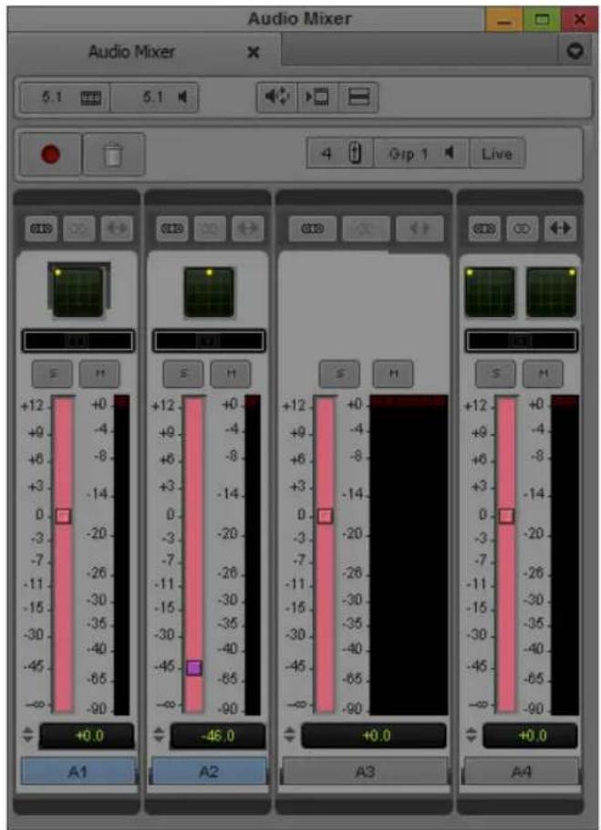
Live Mix level settings at 0 dB and -45 dB
The following illustration shows a sequence in the Timeline with volume automation applied.
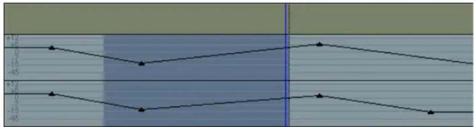
line
| X | Series 1 | Series 2 | |----|----------|----------| | 0 | +12 | +10 | | 1 | +10 | +5 | | 2 | +5 | -5 | | 3 | -5 | -10 | | 4 | -10 | -15 | | 5 | -15 | -20 | | 6 | -20 | -25 | | 7 | -25 | -30 | | 8 | -30 | -35 | | 9 | -35 | -40 | | 10 | -40 | -45 |The following illustration shows the result after choosing Set Live Mix to Automation In/Out from the Audio Mixer Fast menu. The portion of the Timeline between the In and Out on Track A1 is changed to 0 dB and the same portion of Track A2 is changed by -45 dB to match the Live Mix settings. The system adds volume automation keyframes at the In and Out points and creates ramps from the In and Out points to the new value.

flowchart
graph TD
    A["Top Node"] --> B["Left Node"]
    B --> C["Right Node"]
    C --> D["Bottom Node"]
    D --> E["Left Node"]
    E --> F["Right Node"]
    F --> G["Bottom Node"]
    G --> H["Left Node"]
    H --> I["Right Node"]
    I --> J["Bottom Node"]
After changing the levels in this way, you might enter Volume and Pan Automation mode and further adjust the volume between the In and Out points.
Fading and Dipping Audio
In traditional analog editing, you manually change volume levels to smooth audio transitions between elements in an edited sequence by doing any of the following:
- Fading audio up or down.
• Crossfading between audio elements on two separate channels.
• Dipping audio to a lower level.
In Avid editing applications, these effects are more accurately termed “audio dissolves” because they occur instantly when you apply the same dissolve effect that you use for video tracks.
Crossfading in an Avid editing application differs from crossfading in analog editing. In the analog world, unless you are using a mixer, you must lay down audio on two separate channels and fade one down, and then fade up the second on an overlapping section. In an Avid editing application, you simply apply an audio dissolve.
To fade or crossfade audio, use the procedures described in “Using Volume and Pan Automation” on page 813 or the procedure below. To dip audio from a higher level to a lower one — for example, when bringing music down and under a voice-over track, use the procedures described in “Using Volume and Pan Automation” on page 813 or the procedure below.
For an overview of when to use clip volume and when to use volume automation, see “Audio Volume Staging and an Audio Editing Workflow” on page 796.
To apply a fade or crossfade:
- Move the position indicator to a transition.
- Click the Quick Transition button (which appears by default in the second row of buttons below the Record monitor or in the Timeline top toolbar).
The Quick Transition dialog box opens.


- Click the Add menu, and Select Dissolve.
Only dissolves work with audio tracks. - Click the Position menu, and select the location for the dissolve.
- Select a duration for the dissolve by doing one of the following:
▶ Type a duration, measured in frames (30 frames equals 1 second of NTSC footage; 25 frames equals 1 second of PAL footage), in the Duration text box.
▶ Click either the left or right edge of the Dissolve Effect icon, and drag it to change the duration.
The graphic display changes—the size of the effect icon gets smaller or larger, and the numbers in the Duration and Start text boxes change—to reflect the new duration.

The number of frames available for a dissolve depends on how much of the clip has been edited into the sequence. For more information, see “Using the Quick Transition Button” in the Help.
- If you selected Custom Start, type the number of frames before the transition to begin the effect in the "Start n frames before cut" text box. Otherwise, leave the default value in the text box.
- (Option) Click the Target Drive menu, and select a media drive other than the default.
- (Option) If you have In and Out points marked in your sequence, the Quick Transition dialog box contains the following two options:
- Apply to All Transitions (In -> Out)
- Skip Existing Transition Effects

The Skip Existing Transition Effects option is useful when you want to add a number of dissolves to a sequence that already has transition effects.
Do one of the following:
▶ Select Apply to All Transitions (In -> Out) to overwrite all existing transition effects between the In and Out points.
▶ Select both options to avoid overwriting any existing transition effects.
- Click Add to move the effect to the transition point without rendering. Click Add and Render to do both at once.

In most cases, you can select Add and Render for immediate real-time playback of the audio effect (rendering of audio dissolves is usually instantaneous).
The effect is completed.
To apply a dip in audio:
- Play back the section of the sequence where you want to dip the audio to determine the start point for the dip, and apply an add edit to the audio track.
For information on add edit, see “Working with Add Edits (Match Frames)” on page 723. - Repeat the action in step 1 for the end point where the audio dips back up.
- Move the position indicator to the new segment of audio, and open the Audio Mixer tool.
- Adjust the track to the volume level you want, as described in the section "Using Clip Volume and Pan Mode" on page 797.
- Apply a dissolve to both Add Edit points, using the techniques described in “Fading and Dipping Audio” on page 830.
Be sure to click the Position menu, and select Centered on Cut or Custom Start.
After rendering, the audio dips smoothly from the higher levels of the adjacent segments of the track to the lower level applied to the middle segment.
Adjusting Audio Clip Gain in the Timeline
Modifying audio clip gain can be performed directly in the Timeline.
To adjust audio clip gain in the Timeline:
- Load your sequence in the Timeline.
- Do one of the following:
▶ Select Clip Gain for the enabled track. Select Alt + Clip Gain (Windows) or Option + Clip Gain (Macintosh) to enable all tracks.

▶Select Audio Data > Clip Gain from the Timeline Fast Menu.
A fader icon appears for each audio clip. Clip gain values appear in the Timeline for each clip that has clip gain set.
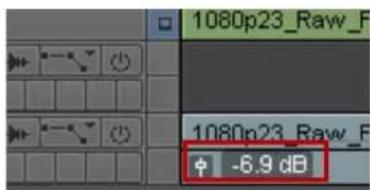
Fader icon and Clip Gain value in the Timeline
- Click the fader icon.
A mini fader opens.

- Slide the fader to adjust the value of the clip gain or enter a value in the fader text box. Option + Click the fader (Macintosh) or Alt + Click the fader (Windows) to reset the value to zero.

You can also move the position bar to the clip you want to adjust, select Alt + Shift and the Up and Down arrows to adjust the clip in one decibel increments.
Audio Sample Rate Conversion
The following options are available for audio sample rate conversion:
- You can perform sample rate conversion on a clip or sequence, as described in “Changing the Audio Sample Rate for Sequences and Audio Clips” on page 834.
- You can perform sample rate conversion as part of a Transcode operation. See “Using the Transcode Command” on page 455.
- You can perform sample rate conversion as part of a Consolidate operation. See “Using the Consolidate Command” on page 451.
- You can perform on-the-fly sample rate conversion while playing when the system encounters different sample rates. See “Audio Projects Settings: Main Tab” on page 1354.
- You can instruct the system to perform sample rate conversion during an import operation if it encounters a sample rate different from the project sample rate. See “Sample Rate Conversion and Audio Import” on page 293 and “Import Settings: Audio Tab” on page 1418.
- You can instruct the system to automatically perform sample rate conversion during capture if it encounters an audio sample rate different from the project sample rate. Sample rate conversion on input applies to the following digital inputs: SDI embedded, AESEBU, SPDIF, and ADAT. For more information, see “Selecting the Audio Sample Rate and Controlling Audio Sample Rate Conversion” on page 199.
Changing the Audio Sample Rate for Sequences and Audio Clips
You can change the sample rate for sequences and audio clips from within the Change Sample Rate dialog box. Because you can combine clips with different sample rates in the same sequence, this feature is useful when you need to ensure that the entire sequence has the same sample rate for a digital cut or export.
For information on setting the sample rate for a project, see “Audio Project Settings for Capture” on page 198.
To change the sample rate for a sequence or an audio clip:
- Select one or more sequences or audio clips in the bin.
- Select Clip > Change Sample Rate.
The Change Sample Rate dialog box opens.
- Choose from the following options:
Option Description
Sample Rate Lets you choose between 32 kHz, 44.1 kHz and 48 kHz, (and 88.2_kHz and 96_kHz if attached to Nitris DX or Mojo DX). The broadcast standard for most high-end video postproduction houses is 48 kHz. Choose the rate based on the requirements of your facility.
Quality Lets you choose the conversion quality: High, Medium, and Low.
Delete Original Media When you select this option, the system automatically deletes the original media after the conversion process completes.
Target Drive Identifies the drive for the new media files. Make sure that you choose a target drive with enough storage space for the generated media files and the ability to play back media.
- Click OK.
Mixing Down Audio Tracks
When you work with multiple audio tracks while editing your material, you might need to mix down the final audio to a multichannel track or to a mono track. When you mix down audio, your Avid editing application inserts the mixdown audio in the next available track in the Timeline by default. You can override the default target track by selecting another one in the Audio Mixdown dialog box.

You cannot mix down compressed audio.
To mix down several edited audio tracks to one or two audio tracks:
- Load a sequence into the Record monitor.
- Click the Track buttons in the Track Selector panel to select the audio tracks you want to mix down.
- Mark an In point and an Out point at the start and end of the material you want to mix down. If you do not mark the section of audio you want to mix down, the system mixes down all of the selected audio tracks.
- Select Special > Audio Mixdown.
The Audio Mixdown dialog box opens. The Source Tracks area lists the source audio tracks and the Range area lists the start and end timecodes for the section of audio you have selected to mix down.

- Select Mono, Stereo, 5.1, or 7.1 and select the target track to which you want to mix down the audio.
A mono mixdown goes to the next available mono track in the Timeline, and a stereo or surround sound mixdown goes to the next available stereo or surround sound track. If there are no appropriate tracks in the Timeline, the mixdown operation creates them.
- Select a drive and a bin.
The drive is the media drive where the system stores the media files for the mixed-down audio.
-
Select Save Premix Sequence if you want to save the sequence before mixing down the audio.
-
Click OK.
Your Avid editing application mixes down the audio, displays the new master clip in the bin, and edits the mixdown clip into the sequence.
Splitting Multichannel Tracks to Mono Tracks
You can split a multichannel audio track in the Timeline into separate mono tracks if you want to edit separate audio channels or if you need to export a sequence either to an older version of the Avid editing application or to Avid Pro Tools. You can also split a clip or sequence with multichannel tracks to mono from a bin. You can split individual multichannel tracks to mono, or you can split all multichannel tracks in your sequence.
When you split a multichannel track, the original multichannel track becomes a mono track and a new mono tracks are added below the original track. For example, if you split a stereo track on A1 in the Timeline, the application makes A1 a mono track holding one stereo channel and adds a second mono track on A2 for the other stereo channel. If A2 already exists in the Timeline, the application renumbers tracks to allow for the split mono tracks. Also, the application renumbers tracks to preserve the odd and even track numbers for left and right mono channels. Renumbered tracks start at the highest track available.
If you duplicate a clip in a bin and split the copy to mono, or if you edit a multichannel clip into a sequence on multiple tracks and split one track to mono, your sequence can contain both a multichannel and a mono instance of the same master clip. This does not cause a problem with editing, playback, or any other operation.

If splitting multichannel tracks to mono tracks causes your sequence to exceed 24 audio tracks, or if splitting to mono cannot maintain the relative order of tracks or the left/right channel alignment, the Avid editing application cannot complete the operation and an error message displays. You can reduce the number of audio tracks in your sequence and retry the operation.
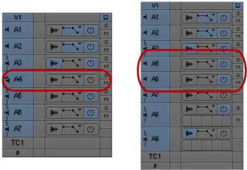
Stereo track A4 (left) split into mono tracks A5 and A6 (right)
When the Avid editing application splits a stereo track to two mono tracks, it changes some audio properties of the track:
- Removes stereo track effects such as RTAS plug-in effects.
- Converts stereo AudioSuite plug-in effects to mono effects.
- Applies any existing volume automation to the resulting mono tracks.
- Applies any existing pan automation to the resulting mono tracks, panning odd-numbered tracks to the left and even-numbered tracks to the right.
- Clears rendered effects. If you have effects on audio segments on stereo tracks, you need to render them after splitting the tracks to mono.
When you split all tracks in a sequent to mono, the Avid editing application automatically duplicates your original sequence and saves a copy to your bin before splitting multichannel tracks to mono.
To split a multichannel audio track to mono, do the following:
▶ Right-click the multichannel track you want to split, and select Split Track to Mono.
Right-click a multichannel clip in a bin that you want to split, and select Split Track to Mono.
The multichannel track splits into mono tracks, with the additional mono tracks added below the original multichannel track. A copy of your original sequence is saved to your bin as [sequence_name].Copy.[number].
To split all multichannel audio tracks in the Timeline to mono, do one of the following:
▶Right-click in the Timeline, and select Split All Tracks to Mono.
▶Select Clip > Split All Tracks to Mono.
All multichannel tracks in the Timeline split into separate mono tracks, with the new mono tracks added below each original multichannel track. A copy of your original sequence is saved to your bin as [sequence_name].Copy.[number].
Using the Audio EQ Tool
The Audio Equalization (EQ) tool supports real-time, segment-based frequency equalization on individual clips, which lets you adjust the high, low, and midrange frequency ranges of an audio clip. You can also save a variety of audio EQ effects and apply them in different circumstances.
To access the Audio EQ tool, do one of the following:
▶Select Tools > Audio EQ.
If one of the Audio tools is already open, click the Effect Mode Selector menu, and select EQ.
The Audio EQ tool opens.
Audio EQ Tool Features
This topic describes the basic buttons and menus on the Audio EQ tool as well as the EQ-specific items on the tool.

Top part of the Audio EQ tool
Button Description
1 Effect icon Lets you create an EQ template. Drag the icon to an open bin to create the template.
2 Audio Loop Play
Lets you make adjustments to an EQ effect while you play the effect. This button is also a mappable button on the Command palette. For more information about using this button, see “Adjusting Volume While Playing a Clip Volume Effect” on page 809.
3 Render Effect Lets you render an effect without leaving the Audio EQ tool.
4 Fast Menu Lets you perform the following tasks:
- Set EQ for enabled tracks.
- Remove EQ for one or more tracks.
- Apply an effect template. See “Using Audio EQ Templates” on page 847.
5 Track Selection Lets you enable tracks for the EQ effect. When you select an item from this menu, the system selects or deselects the corresponding track in the Timeline.

If you enable more than one track in the Timeline, the tracks are designated by plus signs (+) indicating the effect is applied to more than one track.
6 Enable/Disable Lets you enable or disable the current EQ effect. When the button is yellow, EQ Effect the effect is enabled. (The button text "In" stands for "Inline.")
Button Description
7 Bypass RT EQ
Lets you instruct the system to ignore all the EQ effects. This button is also available in the Audio Mixer tool and the Output tab in the Audio Project Settings dialog box. If you select this feature in one place, it is selected in the others as well.
EQ-Specific Features

Bottom part of the Audio EQ tool
1 EQ Parameter display 5 3-band controls
2 Low shelf 6 EQ Range slider
3 Parametric midrange 7 EQ Parameter graph
4 High shelf
The Audio EQ tool provides three bands of control:
- The first band, the low shelf, has four turnover points (50 Hz, 80 Hz, 120 Hz, and 240 Hz). A turnover point is the point at which the curve starts to return to 0.
A shelf affects all frequency values within the range of the shelf. The low shelf affects all frequencies from 20 Hz to the low shelf turnover point. For more information, see “Audio EQ Examples” on page 846.
- The second band is the parametric midrange. This band has two bandwidth values, 1/4 octave and 2 octaves. These values control the width of the curve. For more information, see “Audio EQ Examples” on page 846.
- The third band, the high shelf, has four turnover points (6 kHz, 8 kHz, 12 kHz, and 15 kHz). The high shelf affects all frequencies from the high shelf turnover point to 20 kHz.
The horizontal center line of the graph is 0 (zero). As you move the curve below the zero line, the corresponding frequencies are de-emphasized. Above the zero line, the corresponding frequencies are emphasized. The parametric midrange allows a smooth transition from de-emphasized frequencies to emphasized frequencies.
The In button lets you turn off an individual EQ effect (the currently selected effect). The button is yellow when the EQ effect is on (inline) and gray when the EQ effect is off.
The Ignore EQ option turns off all EQ effects for the sequence. Rendered EQ effects still play correctly.
When you apply Audio EQ effects, consider the following:
- Apply Audio EQ to entire segments only. You cannot isolate portions of a segment for an Audio EQ effect by using In to Out points. You must use add edits (match frames) to mark off a smaller segment.
- Use In to Out points to select a range of complete segments for applying an Audio EQ effect. Segments that fall within the marks, either in part or whole, have the effect applied to them.
The following illustration shows the Audio EQ tool with the frequency response curve displayed and identifies the related areas of the tool.

Example of shelf, parametric midrange, and turnover point information in the Audio EQ tool. The current value for all EQ parameters is 0 dB. Top: buttons that display turnover points (for the low shelf and high shelf curve) and bandwidth (in this case, 2 octaves) around the center point of the parametric curve. Bottom: EQ Range slider showing the center point of the parametric midrange curve.
The Audio EQ tool lets you emphasize or de-emphasize audio frequencies. The height of the curve in the bottom pane shows the amount of emphasis or de-emphasis (also called boost or cut) that is being applied. The range is from +15 dB to -20 dB.
Applying Audio EQ Effects
To adjust audio EQ for a track:
- Load the sequence or clip containing the audio track:
To adjust a track in a source clip, click the Source monitor to make it active.
To view a source clip's tracks in the Timeline, click the Toggle Source/Record in Timeline button.
To adjust a track in a sequence, click the Record monitor to make it active.
- (Option) Isolate a portion of an audio segment by placing add edits.
- (Option) Mark a range of audio segments by adding In to Out points in the track.
- Select Tools > Audio EQ.
- Click and hold the Track Selection Menu button in the Audio EQ tool, and select a track to be adjusted.


Track Selection Menu button in the Audio EQ tool
The Track Selector panel in the Timeline updates to reflect your selection. If you enable multiple tracks in the Timeline, plus signs (+) appear next to the enabled tracks in the Audio EQ tool.
-
Click the Audio Loop Play button to play the currently selected audio clip within the current In to Out range. To stop playing the loop, click the button again or click anywhere in the Timeline.
-
Use one of the following methods to change a value in the Audio EQ tool:
▶ Click a number along the vertical edge of the Low Shelf, Parametric Midrange, or High Shelf sliders.
Click the Low Shelf, Parametric Midrange, or High Shelf slider, and type a value. Values are cumulative until you press Enter (Windows) or Return (Macintosh). For example, if you want to enter the value 12, simply type it. However, if you enter 1 and then want to change the value to 2, press Enter (Windows) or Return (Macintosh) before typing the 2.
▶Click a slider, and then drag the slider to a new position.
Click the EQ Parameter display, and type a value on the numeric keypad.
Set a value of 0 dB by clicking the slider and entering 0, or by clicking 0 along the vertical edge of the Low Shelf, Parametric Midrange, or High Shelf sliders.
- Click the Audio EQ Tool Fast Menu button, and select Set EQ to apply the adjustments to the track.
The command works as follows on the selected tracks:
- In and Out points — Applies the EQ effect to selected tracks between the points.
- An In point (no Out point) — Applies the EQ effect to full clips from the In point to the end of selected tracks.
- No points — Applies the EQ effect globally (across entire tracks).
-
Play through the audio again, using the Audio Loop Play button.
-
Repeat steps 6 to 9 until you are satisfied with the EQ adjustments.
Saving Audio EQ Effects
Your Avid editing application treats an EQ setting as an effect. You can save EQ settings in a bin just as you save any other effect template. This makes it easy to save EQ settings and apply them whenever you need them. The following illustration shows an EQ Effect icon in a bin and in the Timeline.
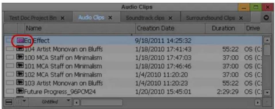

Examples of an EQ effect icon in the bin and in the Timeline
To save EQ settings in a bin:
▶Drag the effect icon in the Audio EQ tool to a bin.
To copy the settings to another audio clip:
Drag the effect icon in the Audio EQ tool to another audio clip in the Timeline.
For more information on using effect templates, see “Working with Effect Templates” in the Help.
Removing Audio EQ Effects with the Fast Menu
You can remove audio EQ effects with the Audio EQ Tool Fast menu or with the Remove Effect button.
The Audio EQ Tool Fast menu lets you remove EQ effects from one track or all enabled tracks and provides access to a number of predefined EQ templates. For a description of predefined audio templates, see “Using Audio EQ Templates” on page 847.
For example, the following illustration shows a segment with one EQ effect applied to the second audio clip on the first audio track. If you select Set EQ In/Out, the current EQ effect is also applied to the first and third audio clips on the first audio track.
![ED 30:00 01:00:00:00 01:00 30:00 01:01:00:00 ED 30:00 01:00:00:00 01:00 30:00 [ 11:01:00:00 ]](/content/2026/05/883817/images/4e7225862e0be88f54f36526dae2e3b8e6cfee16ceac064516ae563a9a47e6d8.jpg)
If there is no EQ setting on the currently selected clip, selecting Set EQ In/Out deletes the EQ settings on all clips within the In to Out range. For example, because there is no EQ setting on the third audio clip in the following example, Set EQ In/Out deletes the EQ effect from the first and second audio clips.
![F0 F1 30:00 01:00:00:00 01:00:30:00 [01:01:00:00 30:00] 01:00:00:00 01:00:30:00 [01:01:00:00](/content/2026/05/883817/images/78af3790321c4f20f8a8c5846f36551f67f594c92c9e94c829a1411070fa3716.jpg)
Set EQ In/Out applies only to the audio track currently selected by the Audio EQ tool. You can change your selected region by eliminating or adding marks in the Timeline, or by selecting a different track.
Removing Audio EQ Effects with the Remove Effect Button
To remove an Audio EQ effect:
- Move the position indicator to the effect in an active track.
- Do one of the following:

▶In Source/Record mode, click the Remove Effect button.
▶In Effect mode, press the Delete key.
Audio EQ Examples
The following procedures are examples of two different ways to use the Audio EQ tool to remove excess bass from an audio track. Assume that a bass drum in the sound track is very pronounced. You want to use the Audio EQ tool to de-emphasize it, but there are voices on the same track as the music. The human voice covers a wide range of frequencies, and the challenge is to preserve the bass frequencies of the voices while de emphasizing the bass drum sound.
Consider that the goal of the adjustments is the final sound. You should use small adjustments to preserve as much of the original sound track as possible. Do not be overly concerned about specific parameter values.
The first procedure adjusts the low shelf to de-emphasize the bass. By dropping the low shelf to -20 dB, you can de-emphasize it. However, there are voices on this track, and simply dropping the low shelf also removes some bass from the voices.
The remaining procedures use the parametric midrange to isolate the particular frequency to de-emphasize.
To compensate for the loss of bass by adjusting the low shelf:
- Use the 2-octave midrange setting to create a wide midrange.
- Move the midpoint of the parametric curve to 88 Hz (Windows) or 90 Hz (Macintosh).
- Boost the midrange of the parametric curve to +7.7 dB.

To isolate the frequency:
- Use the 14 -octave influence range.
- Set the midrange EQ parameter to -15 dB.
- Use the EQ Range slider to move the midpoint of the parametric curve until it isolates the bass frequency.
In this case, the bass frequency to de-emphasize is approximately 80 Hz.

Once you locate the frequency you want, you can adjust it as needed.
To locate a specific frequency and either emphasize or de-emphasize it:
▶Use the ¼-octave influence range and a large negative decibel value.
▶Keep both the high shelf and low shelf set to zero.
▶ Use the EQ Range slider to move the center point of the parametric curve along the frequency range while you play the audio track.
Using Audio EQ Templates
Your Avid editing application provides a set of predefined audio EQ templates. The EQ templates are designed to fix problems that you often encounter with audio clips. For example, Tape Hiss Filter rolls off frequencies above 4 kHz. NTSC Hum Buster cuts the bass on frequencies that often cause hum on NTSC systems. The templates are accessible from the Fast menu in the Audio EQ tool. You can also add your own custom EQ templates to the Fast menu.
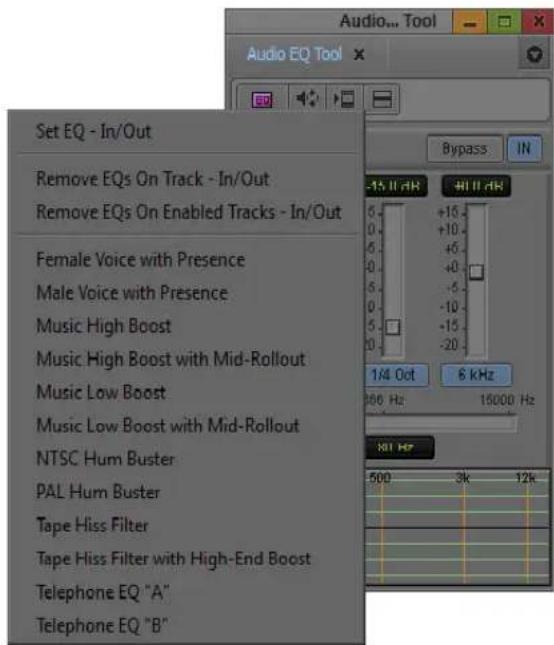
Predefined EQ templates in the Audio EQ tool Fast menu
The following illustration shows the contents of the Audio EQ tool when you select the Female Voice with Presence template in the Timeline. As explained in the tool, you cannot change the parameters of a predefined EQ template.


To see the parameter values of one of the EQ templates that cannot be edited, view the Console window after you apply the effect. For more information, see “Using The Console Window” on page 115.
If you create an EQ effect, you can use it again as a template in another sequence or on another track.
Your Avid editing application stores predefined EQ templates in a special bin named Site_EQs_Bin.avb. You can add your own EQ templates to the Audio EQ Tool Fast menu by storing your EQ templates in the same bin as the predefined templates.
To apply an EQ template from the Audio EQ Tool Fast menu:
- Move the position indicator to the audio clip in the Timeline.
- Click the Audio EQ Tool Fast Menu button, and select the template.
Your Avid editing application places the EQ effect on the audio clip.
To create your own EQ effect template:
- Drag the effect icon from the Audio EQ tool to a bin.
Your Avid editing application creates an EQ effect in the bin. - Rename the template by clicking the text and typing a new name.
To add an EQ template to Site\_EQs\_Bin:
- Open the bin containing your EQ templates.
- Select File > Open Bin.
A dialog box opens. - Navigate to the bin named Site_EQs_Bin.avb in one of the following locations:
(Windows) drive:\Program Files\Avid\Avid editing application\ SupportingFiles\Site_Effects
(Macintosh) Macintosh HD/Applications/Avid editing application/SupportingFiles/Site_Effects - Double-click the Site_EQs_Bin.avb file.
The Site_EQs_Bin window opens. - Drag one of your EQ templates into the Site_EQs_Bin window.
- Name the template by clicking the text and typing a name.
- Close the bin.
Your Avid editing application does not save the effect to the bin until you close the bin. - Click the Audio EQ Tool Fast Menu button, and look for your new template.

Adjusting EQ While Playing an Audio Effect
You can use the Audio Loop Play button to create or change an EQ effect while a clip is playing.
Use the same procedure as described in “Adjusting Volume While Playing a Clip Volume Effect” on page 809.
If the clip has no existing EQ effect before you start, you do not hear any changes until you click the Audio Loop Play button to stop and replay the effect.
As you adjust the EQ values on an existing EQ effect, you might not hear the results immediately. It takes a few seconds for the changes to be applied to the clip.
You can improve the response time by doing any of the following:
- Monitor as few audio tracks as possible.
- Deselect the video track, if practical.
- Use In and Out points to choose a narrow interval to adjust.
Recording Voice-Over Narration
You can use the Audio Punch-in tool to record audio directly into the Timeline for voice-over narration.
Recording voice-over narration directly into your Avid editing application saves you the extra steps of recording the narration to tape first, capturing the narration audio to your Avid system, and then editing the audio clip into the sequence.
Hardware Connections for Voice-Over Recording
Before you can record voice-over narration, you need to connect a microphone or other input device to your system. The following are typical examples:
- Connect a microphone to a mixer, and connect the mixer to the audio interface I/O device on your Avid system.
- Connect a microphone to an external audio device — for example, one of the Mbox family devices — and connect the device to your Avid editing system.
- Connect a microphone to a microphone preamplifier, and connect the preamplifier to the audio interface I/O device on your Avid system.
For information on connecting the hardware, see “Using the Avid Input/Output Hardware” in the Help.
Audio Punch-in Tool Features
You can use the Audio Punch-in tool to record voice-over narration directly into the Timeline. However, you can only record to mono tracks when you use the Audio Punch-In tool.
You can “rehearse” the voice-over while listening to the sequence. The voice-over is not recorded while you rehearse. You can continue to rehearse until you get it right. While recording, you can watch and listen to the sequence and hear the playback of edited sound tracks.
The following illustration shows the features of the Audio Punch-In tool. The following table describes the features of the tool.

Audio Punch-In Tool Feature Description
I Play In/Out button Starts playing with the ability to perform a real-time punch-in. The play loops from the In point to the Out point but stops looping once recording completes. This button blinks bright green while playing.
2 Record button Starts and stops the recording. If you set an In point and Out point, recording automatically starts at the In point and stops at the Out point. This button blinks bright red while recording.
3 Stop button Stops playing or recording and saves the last recorded data. This button is bright blue when recording stops.
Audio Punch-In Tool Feature Description
| 4 Go to Mark In button | Moves the position indicator to the In point. If there is no In point, your Avid editing application goes to where the position indicator was previously located or to the start of the sequence. |
| 5 Cancel button Stops a recording without saving the recorded data. | |
| 6 Audio Tool button Opens the Audio tool so you can monitor and adjust the audio levels during recording. | |
| 7 Input Channels button | Identify the channels on the audio hardware used for recording. Click the appropriate button to select the channel. Alt+click (Windows) or Option+click (Macintosh) the button to display a menu and select another channel.The selected input channels are not used for playback. Do not select the same channels as mix output on the Audio Mixer tool. |
| 8 Passthrough Mix Tool button | Opens the Passthrough Mix tool so you can monitor the audio levels during recording. |
| 9 Punch-In Monitoring button | Allows you to set the Audio Punch-In monitoringAutomatic - Monitoring is not disabled if latency <100ms. If the editing application detects a latency >100ms, monitoring is turned off.On - Audio will monitor IN to OUT during punch-in.Off - Audio will not monitor IN to OUT during punch-in. |
| 10 Preroll and postroll text boxes | Let you provide audiovisual cues before the recording begins and after it ends. For preroll, your Avid editing application backs up the position indicator for the prescribed number of seconds. You can hear the audio during preroll.When starting a punch-in with the Record button, a preroll lets you provide the duration, in seconds, of the audiovisual cue before the recording begins. |

The Record button takes precedence over preroll. During preroll, if you press the Record button, the system starts recording immediately.
11 Handles text box Instructs your Avid editing application to record audio at the beginning and end of the clip. This lets you perform trim edits on the audio.
This feature applies only when you start recording with the Record button. You can record real-time punch-in only until the end of the handle.
12 Input Source menu Includes several optional sources for audio input, depending on your system and audio board.

To view the audio input sources available on your system, see the Input Source menu in the Input tab in the Audio Project Settings dialog box.
Audio Punch-In Tool Feature Description
13 Timeline Track menus Allow you to specify where your Avid editing application places the audio in the Timeline. Select either New Track or an existing track. When you select an existing track, your Avid editing application overwrites the audio on that track and silences that portion during playback. You can only use mono audio tracks for punch-in. You cannot select stereo tracks or locked tracks.
14 Target Drive menu Lets you choose a target drive.
15 Target Bin menu Lets you choose a target bin.
Audio Punch-in Tool Scenarios
You can punch-in audio in several ways:
- Scenario 1 — Set only an Out point. The position indicator is used as the In point. Set a preroll time. Click the Play In/Out button to loop continuously through the sequence. Click the Record button when you find what you want to punch-in, and then click the Record button again to end recording.
- Scenario 2 — Set an In point and an Out point around the material you want to record. Set a preroll time. Click the Record button to start the preroll. When the system arrives at the Out point, recording ends. The last region including the Out point is recorded. Repeat recording over the same region until you are satisfied with the results.
- Scenario 3 — With no In point or Out point set, click the Record button continuously throughout your sequence. Click the Record button to start recording, and then click the Record button again to end recording. Continue this process to record multiple punch-ins.
Recording Voice-Over Narration Using Audio Punch-in
The steps below represent general guidelines for recording audio punch-ins, regardless of your scenario. You should determine when to add the In and Out points, when to use the Play In/Out button, and when to use the Record button, based on your needs. For more information, see the scenarios described in “Audio Punch-in Tool Scenarios” on page 853.

When performing an audio punch-in, the video resolution is dropped a quarter-frame due to bandwidth limitations.
To use the Audio Punch-In tool:
- Load a sequence into the Timeline.
- Select Tools > Audio Punch-In.
The Audio Punch-In tool opens. For information on the buttons and other controls in the Audio Punch-In tool, see “Audio Punch-in Tool Features” on page 851.

Audio Punch-In tool. Top, left to right: Play In/Out button, Record button, and Stop button. Center: Input Source menu. Bottom left: Input Channels buttons. Bottom right: Timeline Track menus.
- Select the input source and input channels that correspond to your hardware setup, and set other values in the window as appropriate.
To select the input channels you want, click and hold the appropriate Input Channels button.
- Click the Timeline Track menus, and select either New Track or an existing track to specify where your Avid editing application places the audio voice-over in the Timeline.
You can only use mono audio tracks for punch-in. You cannot select stereo tracks or locked tracks.
You can replace part (or all) of an existing track, or you can create a new track for the voice-over.
-
(Option) Set In and Out points in the Timeline to specify the part of the sequence to which you want to add narration.
-
Click the Play In/Out button or press the V key.
Loop play begins over the entire sequence. If you set an In point and an Out point, loop play begins from the In point to the Out point.
The Play In/Out button blinks bright green while playing.
- When you are ready to start the voice-over, click the Record button or press the B key.
The Record button blinks bright red while recording, and the Play In/Out button is a steady green. The Audio Meter Channel button in the Audio tool becomes an I and changes to orange.
- Continue to click the Record button to record additional voice-overs.
During the audio punch-in process, you have the ability to record over the duration of the sequence or from the In point to the Out point.
- Click the Stop button, or press the space bar to stop play and recording.
Your Avid editing application automatically names the voice-over and saves it as an audio clip. You can change the clip name as you would for any other clip. The position indicator stops to get ready for your next voice-over.
- (Option) To go to the In point at any time, click the Go to Mark In button.
Your Avid editing application creates one master clip, regardless of how many punch-ins you perform.
The following illustrations show the results of adding a voice-over.
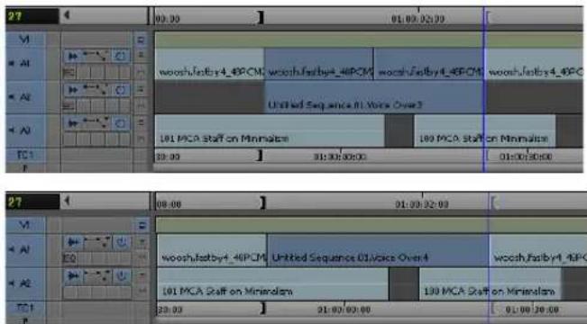
Examples of adding a voice-over in the Timeline. Top: voice-over adding a new track. Bottom: voice-over replacing a portion of a track.
Three Undo functions can be performed during one session. The first undo removes the most recent punch-in, the second undo removes the second-to-last punch-in, and the third undo removes all the punch-ins.
Monitoring Previously Recorded Tracks While Recording Voice-Over Narration
You can monitor previously recorded audio tracks while you record a voice-over narration.
To monitor other audio tracks:
- Select Tools > Audio Tool.
The Audio tool opens.
-
Click the Output Options menu, and select Mono.
-
Record your voice-over as described in "Recording Voice-Over Narration Using Audio Punch-in" on page 853.
-
As you record, monitor the previously recorded audio tracks along with your current recording from the meters in the Audio tool and from the sound on the speakers.
Audio Punch-In Support for Open I/O Devices
If your Open I/O device allows you to record and play simultaneously, you can perform an Audio Punch-In. Check with your 3rd party vendor to see if they support simultaneous record and play.
By clicking on the Punch-In monitoring button in the Audio Punch In tool, you can choose the following monitoring options:
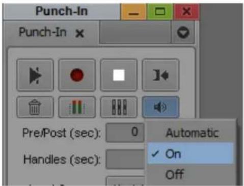
- On - allows for IN to OUT audio monitoring during audio punch-in.
- Off - turns off IN to OUT audio monitoring during audio punch-in. When monitoring is off, the icon in the Punch-In tool changes to indicate punch in monitoring is off. For example, this mode is useful when you want to use another device such as the Mbox to provide local passthrough.
• Automatic - Allows the editing application to detect if monitoring should be On or Off due to detected latency. Monitoring is not disabled if latency <100ms. If the editing application detects latency >100ms, monitoring is turned off. Note: You can choose to override this by setting the monitoring to On.
In some hardware configurations, audio monitoring during Punch-In will not be allowed at all because the hardware does not support it. In this case, the Punch-In tool indicates the monitoring is Off and you cannot override it.
Using Peak Hold While Recording Voice-Over Narration
Peak Hold lets you customize the meter displays, and sets and plays back the internal calibration tone. You can use Peak Hold while recording a punch-in as follows:
• Use the Peak Hold menu in the Audio tool to change between Peak Hold and Infinite Hold.
- Use the Reset Peak button in the Audio tool.

For more information about Peak Hold, see “Understanding the Audio Tool” on page 203.
19 Using External Audio Devices
Avid editing applications support the following external fader controllers or mixers for volume automation and pan recording or as control surfaces.

External fader controllers or mixers are optional. You do not need them to perform volume automation or pan recording on an Avid editing system.
- 002 (Windows only) and Command|8 — These units support touch-sensitive flying faders. While recording volume automation, the faders automatically move. Touch sensitivity means that you can grab a fader and move it during a volume automation recording to quickly punch in a small change in volume. Each track has a separate pan control knob that you can use for pan recording. You can use the 002 as a standalone audio mixer, but not at the same time that you use it as a volume or pan controller or as a control surface. The 002 and Command|8 are the only controllers that can be used as control surfaces to control other parts of your Avid editing application.
You can also use these units as control surfaces for other parts of your Avid editing application. Besides basic functions such as Play, Stop, and Rewind, you can map buttons and menu items to the different buttons on the control surface.
- Mbox family of audio devices — These devices include the Mbox, Mbox Pro, and Mbox Mini. You can use these devices in supported configurations to control audio input and output, as well as to monitor audio playback. For more information, see “Using Mbox Family Audio Devices” on page 872.
- EUCON devices — These devices include the MC Control, MC Mix, and MC Transport. You can use these devices to perform various audio navigation and transport functions as well as some video and audio editing operations such as recording volume automation. For more information, see “Using Avid Artist Series Controllers” on page 890.
The following table compares Avid external controllers and mixers.
Feature Digi 002 (MC/NC only) Command|8 MC Control MC Mix MC Transport
Control surface for Yes Yes Yes Yes (transport
transport controls
and other
functions
Yes
only, no soft keys)
| Feature | Digi 002 (MC/NC only) | Command|8 | MC Control | MC Mix | MC Transport |
| Provides audio play, input, and output | YesNoNoNoNo | ||||
| Record volume automation | Yes Yes Yes Yes | No | |||
| Record pan | Yes Yes Yes Yes | No | |||
| Flying faders | Yes (8) | Yes (8) | Yes (4) | Yes (8) | No |
| Touch-sensitive faders | Yes Yes Yes Yes | No | |||
| Touch-sensitive panners | No | No | Yes Yes | No | |
| Solo/mute | Yes Yes Yes Yes | No | |||
| Supports audio mixing | No^a | No | No No No | ||
| Latch mode | Yes Yes Yes Yes | No | |||
| Number of steps of fader accuracy | 1024 | 1024 | 1024 | 1024 | Not applicable |
a. The Digi 002 can be used as a standalone audio mixer but not at the same time as it is being used as a volume automation or pan controller or control surface.
The following list provides additional information on touch sensitivity and automatically stopping recording:
- Touch sensitivity — As soon as you touch a moving fader on the 002 or Command|8, the unit passes control of the fader to you. For more information, see “Using the Latch Mode Feature on the 002 and Command|8” on page 871.
- Latch mode — In Latch mode, you record gain information only while touching the fader. In Latch mode, recording begins when you touch and ends when you stop playback. For more information, see “Using the Latch Mode Feature on the 002 and Command|8” on page 871.
For more information on using these external fader controllers or mixers, see “Understanding Volume or Pan Automation Recording” on page 817.
Configuring an External Controller
Some fader controllers require specific configuration procedures before you can use the devices with your Avid editing application. For more information, see the following topics:
- “Configuring the Command|8” on page 866
- “Configuring the Mbox Device” on page 873
- “Using Avid Artist Series Controllers” on page 890
For information about using third-party devices, see the documentation that came with your fader controller.
To set the correct port in the Controller Settings:
- Start your Avid editing application.
- Click the Settings tab in the Project window.
- Double-click Controller Settings.
- In the Gain Controller Port menu, select the port that corresponds to your controller.
- Click OK.

An external fader controller is optional. It is not required to perform volume automation recording.
To test the external fader controller:
-
Select Tools > Audio Mixer.
The Audio Mixer tool opens. -
Do one of the following:
▶ Click and hold the Audio Mixer Mode button and select Automation Mode from the menu.
▶Click the Audio Mixer Mode button and cycle through the Audio Mix mode settings to the Automation Mode setting.
-
Click the Audio Mixer Tool Fast Menu button, and select Calibrate Hardware Sliders.
The box changes to blue. -
Check the color of the position indicator lights.
If the external fader controller is connected, at least one of the lights should be on (blue). If the external fader controller is not connected properly, the lights will probably appear gray.
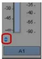
Position indicator lights in the Audio Mixer tool
- Move the faders on the external fader controller.
The corresponding fader should move in the Audio Mixer tool.
Configuring External Controller Settings
You use the Controller Settings dialog box to configure your system so that it can communicate with supported fader controllers. You can use the Controller Settings dialog box for your device to configure several aspects of the controller's behavior:
- You can map the Command palette functions of your choice to the fader controller buttons. For information on mapping Avid Artist Series buttons, see “Customizing Avid Artist Series Controls” on page 902.
- Depending on your controller, you might be able to customize the maximum jog or shuttle speed. You can view footage at the maximum speed when you turn the jog/shuttle wheel all the way to the right or the left position.
Because you cannot map all the Command palette functions to supported controllers, you might want to create multiple Controller settings in the Settings list of the Project window for different sets of editing functions. For more information, see “Duplicating Settings” on page 1342 and “Selecting Among Multiple Settings” on page 1344.
To configure your Avid editing application for a controller and open the Controller Settings dialog box:
- Double-click Controller Settings in the Settings list of the Project window.
The Controller Settings dialog box opens.
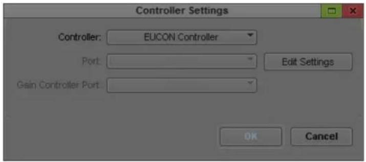
- Click the Port menu, and do one of the following, depending on your operating system, to select the appropriate port:
▶(Windows) Select COM1 or COM2
▶(Macintosh) Select Port #1, #2, #3, or #4
- Select Controller > [controller].
- Click Edit Settings.
The Controller Settings dialog box for your controller opens. For information on the layout of the dialog box and the default button mappings, see the documentation that came with your controller.
To map from the Command palette to the fader controller buttons:
- Open the Controller Settings dialog box for your device.
- If the Command palette is not already open, click Open Command Palette.
The Command palette opens.
- Select 'Button to Button' Reassignment.
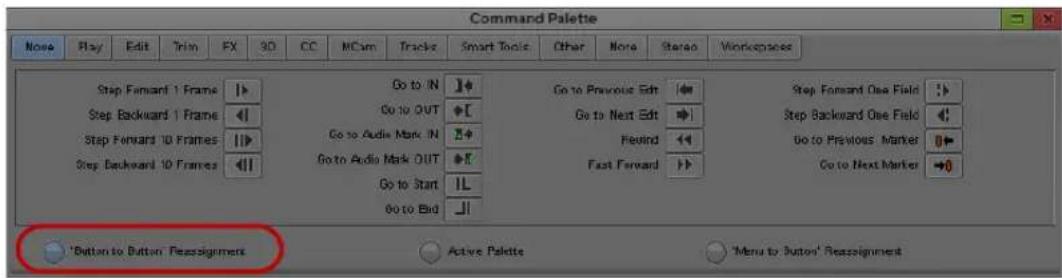
- Do one of the following:
To map an unshifted function, click the function in the Command palette and drag it to the button in the Controller Settings dialog box whose function you want to program.
If your controller uses shifted functions, press and hold the Shift key on your keyboard, click the function in the Command palette, and drag it to the button in the Controller Settings dialog box whose function you want to program.
As you drag between the Command palette and dialog box, the pointer changes to the hand pointer.
The new function appears on the controller button.
Using an External Fader Controller or Mixer to Record Volume Automation
For more information on using third-party controllers with your Avid editing system, see the documentation that came with your device.
To record audio gain information using an external fader controller or mixer:
- Attach the fader controller or mixer to your system.
The position indicator lights change to blue when the fader controller or mixer is on and correctly attached to the system.

Position indicator lights
- Move the blue position indicator to the section of audio that you want to adjust and mark In to Out points.
- Set Preroll and Postroll values, if necessary.
- Click the Record button to start recording your actions.
- Listen to the audio, and when you want to start recording volume information either touch or move the corresponding fader.
Depending on the fader controller or mixer, you might have to click the fader's On button before moving the fader.
- Click the Record button again to stop recording.
- Click the Audio Loop Play button to play the clip and test your results.

- To decrease the number of keyframes, click the Audio Mixer Tool Fast Menu button, and select Filter Volume Automation on Track — In/Out. (Click the Track Selection button for a track to enable Filter Automation.)
If you delete too many keyframes, use the Undo command to restore them.
- Repeat the previous step until you have decreased the number of keyframes to an acceptable level.
You should remove as many excess keyframes as possible while still maintaining the volume changes.
Adjusting the Volume or Pan of Individual Keyframes
To edit the volume for individual keyframes using an external fader controller or mixer:
- Check the color of the position indicator lights.

Position indicator lights
If the external fader controller or mixer is on and is correctly attached to the system, at least one of the position indicator lights on each enabled track is blue.
- Click an audio gain keyframe.
On the 002 (Windows only) and the Command|8, the faders automatically adjust to the volume setting.
- Move the corresponding fader to adjust the volume for the keyframe.
For information on connecting a fader controller or mixer, see “Using an External Fader Controller or Mixer to Record Volume Automation” on page 863.
To edit the pan values for individual keyframes using a 002 or Command|8:
- Click an audio gain keyframe.
- Activate the track on the 002 (Windows only) or Command|8.
- Move the corresponding pan knob to adjust the pan for the keyframe.
Your Avid editing application displays the values in the Pan Value display for the corresponding track in the Audio Mixer tool.
For information on connecting a fader controller or mixer, see “Using an External Fader Controller or Mixer to Record Volume Automation” on page 863.

The position indicator lights do not apply to pan.
Using the 002 and the Command|8
You can use the Command|8 as a control surface for your Avid editing application as well as a controller for volume automation and pan recording.
On Windows systems, you can use the 002 as an audio input and output device for your Avid editing application. You can also make use of its control surface capabilities and use it as a controller for live mix mode and for volume automation and pan recording.

Avid does not support the use of the Avid 002 with Avid video editing applications on Macintosh systems. However, you can use the Avid 002 with Avid Pro Tools on Macintosh systems,
The following table compares some of the features of the 002 and Command|8.
Feature 002 (Windows only) Command|8
| Connection type FireWire USB | |
| Use as an audio device for Avid editing application (play, record, output) | YesNo |
| Works with Avid editors for controlling pan and gain and as a control surface | YesYes |
Using the Command|8 with Your Avid Editing System
The Command|8 is primarily a control surface. You can use it for controlling aspects of the user interface as well as for volume automation and pan recording. You can use it with all Avid editing applications that use Avid input/output hardware.
If your Avid input/output hardware provides four audio channels, you can connect channels 1 and 2 from the input/output hardware to the first Command|8 stereo pair input and connect channels 3 and 4 to the second pair. Then you can switch between the two inputs. If your Avid input/output hardware does not provide four audio channels, you can connect the hardware's audio outputs to one of the Command|8 stereo inputs.
Configuring the Command|8
Before you configure your Command|8 with your Avid editing application, install and configure the device as described in the documentation that comes with Command|8.

You must start Command/8 before you start your Avid editing application. If you start your Avid editing application when the controller is turned off, you must exit your Avid editing application, turn the controller on, and then start your Avid editing application.
To set the correct ports in the Controller Settings dialog box.
- Connect the 002 (Windows only) or Command|8 to your Avid editing system and turn on the unit.
- Start your Avid editing application.
- Click the Settings tab in the Project window.
- Double-click Controller Settings.
The Controller Settings dialog box opens. The Controller menu, Port menu, and Edit Settings button apply to the control surface. For Windows systems, you can use either an 002 or a Command|8. For Macintosh systems, you can use a Command|8. The Gain Controller Port applies to any controller that you connect for volume automation or pan recording.
- From the Controller menu, select one of the following:
▶002 Controller (Windows only)
▶Command|8
- From the Port menu, select one of the following:
▶Windows - “002 Control Port” or “C|8 Surface”
▶Macintosh - Command|8 Port 1
- From the Gain Controller Port menu, select a controller for volume automation or pan recording.
The Gain Controller Port menu displays all COM or MIDI ports that are available on the system.
- (Option) Click Edit Settings to view or modify the button assignments.
Mapping Buttons and Menu Commands for the Avid 002 or Command|8
On Windows systems, you can map the buttons in the 002 Controller Settings dialog box to buttons on the Command palette and to menu commands.
The buttons on the 002 (for Windows systems only) and Command|8 can have different functions depending on the modifier key you press. You can either use the keyboard or press one of the Keyboard Modifier switches on the controller surface.

For the 002 and the Command/8, pressing the Option key on a Macintosh system is equivalent to pressing the Alt key on a Windows system. Pressing the Command key on a Macintosh system has no equivalent on a Windows system.
To display the dialog box for mapping buttons and menu commands:
▶ Click the Edit Settings button in the Controller Settings dialog box.
The 002 Controller Settings or Command|8 Controller Settings dialog box opens.
The following illustration shows the 002 Controller Settings dialog box.

Groups of controls in the 002 Controller Settings dialog box. Top left: Console View controls, Display Controls and Foot Switch. Center left: Keyboard Modifier switches. Bottom left: Open Command Palette button. Right: Transport and Navigation controls.
The following illustration shows the Command|8 Controller Settings dialog box.

Groups of controls in the Command|8 Controller Settings dialog box. Top, left to right: Console View controls, Transport and Navigation controls, Display Controls and Foot Switch. Center: Keyboard Modifier switches. Bottom: Open Command Palette button.
To view the different button settings on the Controller Settings dialog box:
Press the Shift, Control, Option, or Command key while viewing the Command|8 Controller Settings dialog box.
Mapping Controller Menu Commands for the 002 or Command|8
You can change the Keyboard Modifier switches by selecting a new button from the appropriate menu in the Keyboard Modifiers area.
Each Controller Settings dialog box has an Open Command Palette button. Use the standard techniques for mapping buttons and menu selections from the Avid interface to the buttons on the control surface. For more information, see “Mapping User-Selectable Buttons” on page 112 and “Mapping Menu Commands” on page 113.
To map a menu command to a button on a Controller Settings dialog box:
- Click the Settings tab on the Project window.
- Double-click Controller Settings.
The Controller Settings dialog box opens.
-
From the Controller menu, select either 002 Controller (Windows only) or Command|8.
-
Click Edit Settings.
The 002 Controller Settings dialog box or Command|8 Controller Settings dialog box opens. - Click Open Command Palette.
The Command palette opens. - Click Menu to Button Reassignment on the Command palette.
As you move the mouse over a button, the cursor changes to a menu icon. - Click the button on the dialog box that you want to change.
The system highlights the button. - Select a menu command. For example, select Tools > Audio Punch-In.
The system maps the menu command to the button. - When you finish mapping menu commands, click Active Palette on the Command palette or Button to Button Reassignment to map buttons.
- When you finish mapping menu commands and buttons, click OK to save your changes.
The 002 Controller Settings dialog box or the Command|8 Controller Settings dialog box closes and the Controller Settings dialog box appears. - Click OK.
The system makes the new button assignments.

The assignments do not take effect until you click OK in both dialog boxes.
Using 002 or Command|8 Buttons to Change Focus in your Avid Editing Application Interface
Many buttons perform different functions depending on which window in the Avid interface is active. For example, if the Timeline is active, pressing Play plays the sequence in the Timeline. If a bin is in Frame view and a clip is selected, pressing Play plays the footage in the clip.

You cannot assign a function to the F1 key on a Command/8. The F1 key is a local function on the device.

Do not press the Standalone button on the 002 while you are using it as a control surface for your Avid editing application. This puts the controller in Standalone mode and closes the FireWire connection. To use the controller again, you must exit your Avid editing application, power cycle the controller, and then restart your Avid editing application.
To ensure that you perform the correct operation when you press a button on the control surface:
- Map some buttons to menu commands that makes a particular window or tool active.
For example, on the 002, the F5 key is mapped to Tools > Timeline by default for Windows systems. Pressing the F5 button on the 002 makes the Timeline active. - (Option) To see the function of a mapped button, hold the cursor over the button to view the tooltip.
Using a Foot Pedal as a Foot Switch with the 002 or Command|8
The 002 (Windows only) and Command|8 each have a connection on the back for a foot pedal. The system accepts any “normally open” foot pedal. For example, you can use a standard normally-open sustain pedal for an electronic keyboard.
You can assign any button or menu item to the foot pedal. By default, the system assigns the foot pedal to the Record button on the Audio Punch-In tool. You could also assign the foot pedal to the Shift key function.
Switching Between the 002 and Command|8
The button mappings for the 002 for Windows systems carry over to the Command|8. The button-mapping dialog boxes for the 002 and Command|8 are set up differently to match the layout of the controllers, but the same settings are used for both controllers.
There are several buttons on the Command8 that are not on the 002:
• M o n 0
- Default
• M e m L o c k
These buttons appear in the Command|8 Controller Settings dialog box and do not appear in the 002 Controller Settings dialog box.
Using a 002 or Command|8 to Record Pan
To record pan information using a Command|8:
- Attach the 002 (Windows only) or Command|8 to your system. (See “Configuring the Command|8” on page 866.)
The position indicator lights change to blue when the fader controller or mixer is on and correctly attached to the system.

Position indicator lights
- Click the Timeline Fast Menu button and select Audio Data > Pan.
- Move the blue position indicator to the section of audio that you want to adjust and mark In to Out points.
- Set Preroll and Postroll values, if necessary.
- Click the Record button to start recording your actions.
- Listen to the audio and turn the pan knob for the track.
The system displays the values in the Pan Value display for the corresponding track in the Audio Mixer tool.
-
Click the Record button again to stop recording.
-
Click the Audio Loop Play button to play the clip and test your results.
-
To decrease the number of keyframes, click the Audio Mixer Tool Fast Menu button, and select Filter Pan on Track — In/Out. (Click the Track Selection button for a track to enable Filter Automation.)
-
(Option) If you delete too many keyframes, use the Undo command to restore them.
-
Repeat step 9 until you have decreased the number of keyframes to an acceptable level.
You should remove as many excess keyframes as possible while still maintaining the pan changes.
Using the Latch Mode Feature on the 002 and Command|8
The 002 (Windows only) and Command|8 have a Latch Mode button for each track that lets you easily punch-in and punch-out small sections of volume automation information. The Channel View buttons on the 002 are used as the Latch Mode buttons. These buttons are directly above the display on the 002 and directly below the display on the Command|8. The first two buttons are labeled EQ and Dynamics.
When a fader is not in Latch Mode, it automatically stops recording as soon as you release it. When you release the fader, it begins moving again as it follows the volume information in the Timeline.

The light inside the Latch mode button is on when a fader is not in Latch mode.
To use Latch Mode:
- Click the Latch Mode button for the appropriate tracks on the controller. You can click the button before or during a recording session.
- Set In and Out points, and click the Record button. The system begins playing the section and the faders move accordingly.
- When you want to make an adjustment, move the fader to change the volume. The system immediately begins recording.
- When you are finished adjusting the section, release the fader.
The system stops recording (but keeps playing) and the fader snaps back to the level in the Timeline.
When the track is in Latch mode, the system continues to record audio volume information after you release the fader.
- (Option) Press the Latch Mode button to stop recording and snap the button back to its current Timeline position.
Using Mbox Family Audio Devices
You can use the Mbox ^® family of audio input/output hardware as external audio devices for your Avid editing application. This means you can use the Mbox devices to record source audio and to monitor output audio.
When you attach the Mbox device to your Avid editing system, all of its audio input and output connections are live. If you use a video input/output hardware device, you can use an Mbox device with either a USB or an IEEE 1394 (FireWire) connection. (For more information on using an input/output device with a 1394 connection, see “Selecting a DV Device” on page 234.) The Mbox device and the video I/O device remain as two separate audio sub-systems. They are not combined to increase the number of available audio channels. For audio input/output, the system creates a list of input options based on the audio devices that are present — for example, Mbox Mic/Line, Mbox S/PDIF, or Host 1394.
The following table lists some of the features of the Mbox 2 and the Mbox (3rd Generation) family of audio devices.
Device Connection Type Input/Output Types
Mbox 2 USB Analog, S/PDIF, MIDI
Mbox 2 Pro 1394 Analog, S/PDIF, MIDI, Word Clock In
Device Connection Type Input/Output Types
Mbox 2 Mini USB Analog
Mbox 2 Micro USB Analog (monitor audio only; no input/output available)
Mbox (3rd Generation) USB Analog, S/PDIF, MIDI
Mbox Pro (3rd 1394 Analog, S/PDIF, MIDI, Word Clock In Generation)
Mbox Mini (3rd USB Analog Generation)
Mbox (3rd Generation) devices support audio sample rates up to 96 KHz. For a full description of MBox specifications, see the documentation that came with your device.
For a list of currently supported Mbox devices, see the ReadMe for your Avid editing application.
Configuring the Mbox Device
You must start the Mbox device before you start your Avid editing application. If you start your Avid editing application when the audio device is turned off, you must exit your Avid editing application, turn the device on, and then start your Avid editing application.

(Macintosh only) S/PDIF inputs appear in the Capture tool as Tracks 3-4.
To select the Mbox device in the Audio Project Settings dialog box.
- Connect the Mbox device to your Avid editing system.
- Start your Avid editing application.
- Click the Settings tab in the Project window.
- Double-click Audio Project Settings.
The Audio Project Settings dialog box opens.
- Click the Hardware tab.

- Click the Peripheral menu, and then select your Mbox device.
- Close the Audio Project Settings dialog box.
Once you configure the Mbox device, you can select the audio input interface in the Capture tool and the Audio Punch-in tool. For more information, see “Preparing to Capture Audio” on page 198 and “Recording Voice-Over Narration” on page 850.
You can also use your device to monitor output audio by connecting headphones or speakers to the Mbox device.
Setting Up the Mbox Pro for Passthrough Monitoring (Windows Only)
If you use the Mbox Pro to monitor source audio, you must set the source for your headphone output in the Mbox Pro Control Panel to Stereo Mix 1. This allows you to monitor audio with your Avid editing application using the Passthrough Mix tool.
To set your Mbox Pro to monitor passthrough audio:
- Make sure your Avid editing application is not running.
- Click the Start button, and select Control Panel.
- Do one of the following:
▶(Windows 7) If the View by menu is set to Category, click Hardware and Sound, and then click Avid Mbox Pro.
(Windows 7) If the View by menu is set to Large icons or to Small icons, click Avid Mbox Pro.
▶(Windows XP) Click Avid Mbox Pro.
The Mbox Pro Control Panel opens.
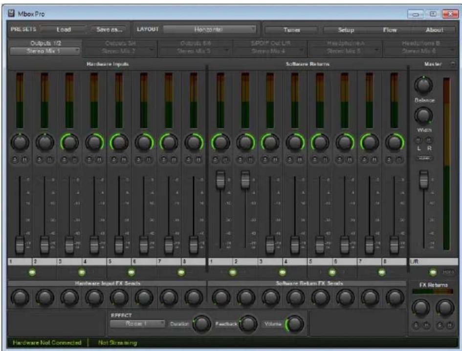
-
Select your headphone output, and then click the Audio Source menu and select Stereo Mix 1.
-
Close the Mbox Pro Control Panel.
Configuring USB-to-MIDI Software for External Controllers
If your fader controller uses USB-to-MIDI software, you can install and configure the software to recognize your fader controller once you have connected a fader controller to your Avid editing system.
For information on connecting your controller and installing USB-to-MIDI software, see the instructions that came with your controller.
Testing External Fader Controller Connections
To test the external fader controller connections:
- Connect all MIDI hardware devices.
MIDI port A is the default port used by the Avid system. To change the port configuration, see “Switching Between MIDI Connections on the USB-to-MIDI Converter” on page 877.
- Move the sliders on the fader controller, and confirm that the MIDI In LED indicator on the USB-to-MIDI converter turns on and off appropriately.
The USB LED indicator pulses — this is expected behavior.
- Start your Avid editing application, and open the Project window.
- Click the Settings tab and double-click Controller Settings.
The Controller Settings dialog box opens.
- Choose the appropriate port for the device from the Gain Controller menu.
- Click OK.
- Select Tools > Audio Mixer.
- Do one of the following:
▶ Click and hold the Audio Mixer Mode button and select Automation Mode from the menu.
▶Click the Audio Mixer Mode button and cycle through the Audio Mix mode settings to the Automation Mode setting.
- Click the Audio Mixer Tool Fast Menu button, and select Calibrate Hardware Sliders.
If the external fader controller is connected and the system is using the correct MIDI port, then the Audio Mixer tool displays the following:
- At least one of the position indicator lights is on (blue).
- The Recording Status Light changes to gold.

Position indicator lights
-
If the lights do not change to blue, see “Troubleshooting MIDI Connections” on page 877.
-
To disable the hardware calibration, click the Audio Mixer Tool Fast Menu button, and select Calibrate Hardware Sliders.
The Recording Status Light changes to black.
- Move the sliders on the external fader controller.
The corresponding sliders move in the Audio Mixer tool.
Now you are ready to use the fader controller with your Avid editing application. For more information on using the Audio Mixer tool, see “Using Volume and Pan Automation” on page 813.
Switching Between MIDI Connections on the USB-to-MIDI Converter
If you need to switch to a different MIDI port connection, change the hardware connections and then make the appropriate change in the Controller Settings dialog box.
To change the MIDI port connection in your Avid editing application:
- Click the Settings tab in the Project window.
- Double-click Controller Settings.
The Controller Settings dialog box opens.
- Select the correct MIDI port from the Gain Controller menu.
- Click OK.
- Select Tools > Audio Mixer.
- Do one of the following:
▶ Click and hold the Audio Mixer Mode button and select Automation Mode from the menu.
▶Click the Audio Mixer Mode button and cycle through the Audio Mix mode settings to the Automation Mode setting.
If the fader or mixer is on and correctly configured, the indicator lights on the Audio Mixer tool should change to blue. If the lights do not change to blue, see “Troubleshooting MIDI Connections” on page 877.
Troubleshooting MIDI Connections
Do the following if the Audio Mixer tool does not respond to the external fader controller:
- Make sure the MIDI hardware devices are connected and configured.
For more information, see the documentation that came with your fader controller.
-
Check that the MIDI cable connections are correct. Check that the cables are connected from Out to In and from In to Out.
-
Check the Controller Settings dialog box in the Settings list of the Project window. Verify that the correct Gain Controller port is selected.
- (Macintosh only) Use the Apple System Profiler to check whether the system is recognizing the MIDI device:
a. Select Apple menu > About This Mac.
b. Click More Information.
The Apple System Profiler opens.
c. Click the Devices and Volumes tab.
The USB Information portion of the display identifies the USB devices that the system recognizes. The system might not display the name of each device, but the number of USB devices should match the number of devices you have connected to the system.
Avid HD Native and Pro Tools|HD Hardware Configuration for Avid Editing Systems
Avid Pro Tools v8.5 and later supports HD Native audio hardware, and Pro Tools v9.0 and later supports both HD Native and Pro Tools|HD hardware. If you install your Avid editing application on a system with Pro Tools HD, you can use the same audio hardware for both applications. The supported versions of Avid Pro Tools installs the necessary audio drivers.
Not all versions of Avid editing applications are compatible with Pro Tools|HD and HD Native hardware. For up-to-date information on co-installation and supported configurations, see the ReadMe for your Avid editing application.
If you use 3rd party hardware or if you have Avid DX hardware installed with your system, you cannot access Pro Tools|HD or HD Native hardware. You can use this hardware in a software-only Avid editing system or with supported Avid hardware in 1394 mode.

Pro Tools/HD and HD Native audio hardware is supported only in some co-installation configurations, and for Pro Tools v9.0 the HD hardware is supported only on Macintosh systems and 32-bit Windows systems. For more information about co-installation, see the ReadMe documentation that came with your Avid editing application.
With Pro Tools|HD or HD Native hardware installed on a supported Avid editing system, you can perform the following:
- Play back audio through up to 8 audio outputs. You can also play back audio with a SYNC HD or SYNC I/O device connected. The Avid editing application does not control the clock settings for these devices.
- If you have multiple audio interfaces connected (“daisy-chained”) to your Pro Tools|HD or HD Native card, the playback defaults to outputs 1 and 2 of the first device.
- The Avid editing application can input and output audio up to 48 kHz with HD or Native hardware.
To set up your system to use Pro Tools|HD or HD Native hardware with your Avid editing application, see the following topics:
- “Configuring the ASIO Driver (Windows)” on page 879
- “Configuring the Core Audio Driver (Macintosh)” on page 881
Configuring the ASIO Driver (Windows)
You can configure the ASIO driver settings by using the ASIO Control Panel, which you access from the Audio Project Settings dialog box.
To configure the ASIO driver:
- In the Avid editing application, click the Settings tab in the Project window.
- Double-click Audio Project in the Settings list.
The Audio Project Settings dialog box opens. - Click the Hardware tab.

- Click the Control Panel button.
The ASIO Control Panel opens.

- (Optional) Click the Buffer Size menu and select a buffer size.
Generally, smaller buffer sizes are preferable. However, if you experience any problems with performance (such as clicks and pops during recording or playback), try increasing the Buffer Size setting.
-
Click the Device menu and select the audio device connected to your Pro Tools|HD or HD Native hardware.
-
Click Advanced.
The Hardware Setup dialog box opens.
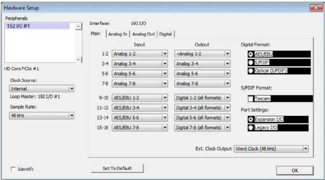
- Select the options you want for your audio input/output operations. For more information on the settings in the Hardware Setup dialog box, see the user guide that came with your Pro Tools system.
Your Avid editing application uses only 8 channels of audio output. Also, the application controls the audio sample rate, not your Pro Tools|HD or HD Native hardware.
-
Click OK to close the Hardware Setup dialog box.
-
Click OK to close the ASIO Control Panel.
Once you configure the audio device, you can use your device to monitor output audio by connecting headphones or speakers to the audio device.
- Close the Audio Project Settings dialog box.
Configuring the Core Audio Driver (Macintosh)
You can configure the Core Audio driver using the Avid Core Audio Manager application. The Core Audio Manager application launches automatically the first time your Avid editing application accesses the Core Audio driver — for example, the first time you play audio on a system with an HD Native or Pro Tools|HD card installed. If the Core Audio Manager icon is hidden when first launched, click the icon in the dock.
Use Core Audio Manager to change the Core Audio Buffer Size setting and control volume and mute for the Core Audio Driver. Core Audio Manager also identifies your audio hardware, the supported number of input and output channels and the number of attached clients (applications).
To configure the CoreAudio driver:
1. Do one of the following:
If your Avid editing application is running and you have an audio sequence loaded in the Source/Record monitor, click Play and then click the CoreAudio Manager icon in the dock.
▶ Double-click the CoreAudio Manager file (located in /Applications/Digidesign/).
The CoreAudio Manager opens.

2. (Optional) Click the Buffer Size menu and select a buffer size.
Generally, smaller buffer sizes are preferable. However, if you experience any problems with performance (such as clicks and pops during recording or playback), try increasing the CoreAudio Buffer Size setting. You can also change the buffer size from within the Avid editing application if it is the only client attached to the CoreAudio Driver.
3. Click HW Setup.
The Hardware Setup dialog box opens.
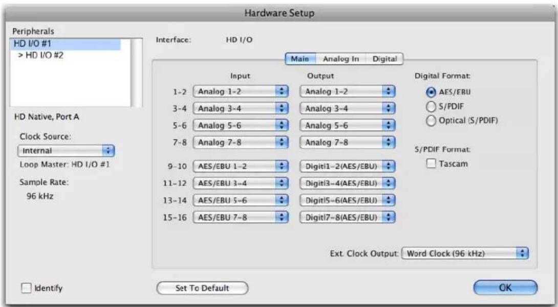
- Select the options you want for your audio input/output operations. For more information on the settings in the Hardware Setup dialog box, see the user guide that came with your Pro Tools system.
Your Avid editing application uses only 8 channels of audio output. Also, the application controls the audio sample rate, not your Pro Tools|HD or HD Native hardware.
- Click OK to close the Hardware Setup dialog box.
Once you configure the audio device, you can use your device to monitor output audio by connecting headphones or speakers to the audio device.
- If your Avid editing application is not running, you can click Quit to close the CoreAudio Manager.

If the Avid editing application connected to the CoreAudio Manager is running when you quit the Manager, you might receive an error message and lose your connection to the Pro Tools hardware.
- Close the Audio Project Settings dialog box.
Using a GPI Device with the Audio Punch-In Tool
Your Avid editing application can send signals to a V-LAN ^® VLXi ^® deck controller and a general-purpose interface (GPI) device that trigger GPI actions. These signals are sent when playback begins and ends, and also when recording with the Audio Punch-In tool begins and ends.
If you have a V-LAN VLXi deck controller and a GPI device connected to your Avid system and they are configured correctly, you can use the GPI to control additional external hardware while you are working with the Audio Punch-In tool. For example, you might want to control an indicator light in a recording studio to provide a visual cue for performers or a control light outside the studio that indicates when recording is in progress.
To make use of this feature, you must:
- Understand when your Avid editing application sends GPI trigger signals. For more information, see “Understanding GPI Trigger Signals” on page 884.
- Connect a V-LAN VLXi deck controller and a VLXi-GT GPI to your Avid system. For more information, see “Connecting a V-LAN VLXi Controller and GPI” on page 885.
- Configure the V-LAN VLXi deck controller and the GPI. For more information, see “Configuring a V-LAN VLXi Controller and GPI” on page 886.
- Create GPI settings for your specific needs. For more information, see “Working with GPI Settings” on page 887.
Understanding GPI Trigger Signals
Your Avid editing application sends three different GPI trigger signals under the following circumstances:
Trigger Signal Sent When
Play Out Playback begins.
Recording with the Audio Punch-In tool ends but playback continues because a postroll value is set in the Audio Punch-In tool (that is, the signal is sent when the Stop button in the Audio Punch-In tool changes to blue).
Record Out Recording with the Audio Punch-In tool begins.
Stop Out Playback stops.
For more information on using the Audio Punch-In tool, see “Recording Voice-Over Narration Using Audio Punch-in” on page 853.
GPI Signal Sequences
GPI signal sequences differ, depending on whether or not you are using the Audio Punch-In tool with preroll and postroll.
When you use the Audio Punch-In tool without any preroll or postroll, the following occurs:
- Record Out is sent when recording begins.
- Stop Out is sent when recording (and playback) ends.
When you use the Audio Punch-In tool with preroll and postroll, the following occurs:
- Play Out is sent when preroll begins (the position indicator begins moving in the Timeline, and the Play In/Out button in the Audio Punch-In tool blinks green).
- Record Out is sent when recording begins (the Record button in the Audio Punch-In tool blinks red).
- Play Out is sent when recording ends and postroll begins (the Stop button in the Audio Punch-In tool changes to blue).
- Stop Out is sent when postroll ends (the position indicator stops moving).

Record Out and Play Out repeat if you perform additional recordings.
Example of Linking GPI Actions to Trigger Signals
You can configure the GPI to respond to each signal sent by your Avid editing application in a specific manner. For a simple indicator light, you might create a GPI setting linking the Record Out signal from your Avid editing application to the GPI Set action (to turn the light on) and a setting linking the Stop Out signal from your Avid editing application to the GPI Reset action (to turn the light off).
For information on GPI actions, see “Working with GPI Settings” on page 887.
If you are working with preroll and postroll values, you might also link the Play Out signal to the GPI's Pulse action to flash the light on and off repeatedly during the preroll and postroll periods. (Since the Pulse action does not switch between on and off very rapidly, your preroll and postroll durations might need to be quite long to allow for the light to flash enough times to be meaningful.)
For more information on configuring the GPI, see “Configuring a V-LAN VLXi Controller and GPI” on page 886.
Connecting a V-LAN VLXi Controller and GPI
The V-LAN VLXi controller and VLXi-GT GPI connect to your Avid system through a direct serial connection as shown in the following illustration.

Top left: GPI terminals on the VLXi-GT GPI (for connections to external hardware). Top right: V-LAN connection (from VLXi-GT to V-LAN VLXi controller) and terminator (required when cable length is more than 50 feet (15.24 meters). Bottom: Serial connection from V-LAN VLXi controller serial port connector to serial port connector on your Avid system (or on a USB-to-serial adapter). Note that all cables are customer supplied.
You must configure the V-LAN VLXi controller to work with the VLXi-GT GPI. Assign the VLXi-GT to a V-LAN node address between 16 and 19. LAN connections of more than 50 feet (15.24 meters) must have a terminator. For more information on configuring the V-LAN, see the Videomedia VLXi User's Guide.
Configuring a V-LAN VLXi Controller and GPI
Once you have connected a V-LAN VLXi controller and VLXi-GT GPI to your Avid system, you can configure the system to communicate with the controller and the GPI, and create GPI settings appropriate to your needs. For more information on creating settings, see “Working with GPI Settings” on page 887.
To configure the V-LAN VLXi controller and the VLXi-GT GPI:
- In the Project window, double-click Deck Configuration.
The Deck Configuration dialog box opens.
- Click Add Channel.
- Click the Channel Type menu, and select VLAN VLX.
-
Click the Port menu, and select the serial port to which the V-LAN VLXi is connected.
-
Click OK.
The Autoconfigure message box opens.
- Click Yes.
The connected GPI is automatically detected and appears in the Deck Configuration dialog box.
Working with GPI Settings
You must create a separate GPI setting for each trigger signal you want the GPI to recognize. For example, you would need one setting for the Record Out signal and another for the Stop Out signal.
You can also edit an existing GPI setting or delete a GPI setting so that it no longer appears as an option in the GPI Settings dialog box.
To create a GPI setting:
- In the Project window, double-click Deck Configuration.
The Deck Configuration dialog box opens.
- Double-click the VLXi-GT text box.
The GPI Settings dialog box opens.
- Select the appropriate settings.
For more information about GPI settings option, see “GPI Settings Options” on page 888.
- Click Add.
The GPI Node Settings dialog box opens.
- Select the appropriate settings.
For more information about GPI Node settings option, see “GPI Settings Options” on page 888.
- Click OK.
The GPI Settings dialog box opens.
-
Click OK to set the GPI.
-
Click Apply in the Deck Configuration dialog box.
To edit a GPI setting:
- In the Project window, double-click Deck Configuration.
The Deck Configuration dialog box opens.
-
Click the VLXi-GT text box.
-
Select the name of the GPI you want to edit.
- Click Edit.
- Make the applicable changes to the setting.
- Click OK.
- Click Apply.
The GPI setting is updated.
To delete a GPI setting:
- In the Project window, double-click Deck Configuration.
The Deck Configuration dialog box opens. - Click the VLXi-GT text box.
- Select the name of the GPI you want to delete.
- Click Delete.
- Click OK.
- Click Apply.
The GPI setting is deleted.
GPI Settings Options
The following tables describe the GPI settings and GPI Node settings options.
GPI Option Description
| Name | Keep the default V-LAN VLXi name, or type a new name. |
| Description (Option) Add a description of the GPI trigger. | |
| Device Type Select V-LAN, which is the Avid-supported device type. | |
| Address | Select the V-LAN network address to which the VLXi-GT is assigned. Valid addresses on the V-LAN network are 16 through 19. This address must match the internal V-LAN address. |
| Pulse Duration Leave this setting at its default value; it does not alter the length of the Pulse action in the GPI. | |
| GPI Control Enable When you deselect this option, you disable the GPI but keep the GPI settings. This is useful for troubleshooting purposes. | |
| Edit Click to edit an existing GPI node setting. | |
GPI Option Description
Delete Click to delete an existing GPI node setting.
Add Click to add another GPI node setting.
GPI Node Option Description
Function Select one of the three active functions:
- Record Out
- Play Out
- Stop Out
Seven options are listed, but only the three signals described in “Understanding GPI Trigger Signals” on page 884 are active.
Node Click the Node menu, and select a node. Nodes 1 through 6 correspond to the physical connectors on the back of the VLXi-GT GPI device.
Action Select an action:
- Set activates a command.
- Reset deactivates a command.
- Pulse switches the state between active and inactive.
20 Using Avid Artist Series Controllers
This section includes topics that provide information on configuring and using the Avid Artist Series controllers with your Avid editing application: Avid Artist Control, Avid Artist Transport, and Avid Artist Mix. These controllers employ the EUCON ^™ (Extended User Control) protocol, which allows for integrated control of your Avid editing application and EUCON-compatible devices. You can use the controllers with your Avid editing application to perform audio navigation and transport functions, as well as some video and audio editing features such as recording volume automation.
• Installing EuControl Software
- Configuring Avid Artist Series Controller Settings
- Configuring Ethernet Connections (Macintosh)
- Setting the IP Address
- Configuring EuControl Settings
• Artist Series Controller Button Mappings
- Customizing Avid Artist Series Controls
- Moving Through Footage with Artist Series Controllers
• Volume Automation and Pan on Artist Series Controllers
• Recording Volume Automation and Pan with Artist Series Controllers
• Using the Latch Mode Feature on Artist Series Controllers
• Using the Artist Series Controller for Editing Media
- Controller Application Sets
Installing EuControl Software
The EuControl application controls your Artist Series controller and communicates with your Avid editing application. You must install EuControl before you use any Artist Series controller.
If you want to connect your Artist Series controller to an Avid editing system that is part of an Avid ISIS shared storage environment, the following requirements apply:
- (Macintosh only) Avid recommends that you connect your Artist Series controller to the built-in Ethernet 1 port on your Macintosh system. If you have limits to the number of Ethernet connections you use — for a corporate network or for shared storage — you might need to set the service order for your Artist Series controller to a lower priority than your other Ethernet connection. For more information on configuring your Ethernet connections, see “Configuring Ethernet Connections (Macintosh)” on page 893. You can change port assignments in the EuControl Settings application if necessary.
- Avid also recommends that you disable the network interface you use for your Artist Series controller in the ISIS Client Manager preferences. This prevents ISIS from trying to use the Ethernet port assigned to EUCON for your shared storage operations. For more information, see the Avid ISIS Client Guide that came with your ISIS product.
- Avid ISIS supports dual Ethernet connections to maximize bandwidth use and increase performance. Since your Artist Series controller must use one Ethernet port to connect to your Avid editing system, Avid does not support dual connection on Macintosh systems connected to an ISIS switch.
- Artist Series controllers do not support connection through a third-party Ethernet card.
To install EuControl:
- Do one of the following:
If you downloaded the latest software from the Avid Web site, double-click the installer.
Insert the installation CD into your system, and double-click the installer.
- Follow the on-screen instructions to install the software.

Download the most current version of EuControl if prompted to do so during installation.
When installation completes, EuControl launches automatically.
- You should check for updated firmware for your Artist Series controller by doing the following:
a. Do one of the following:
▶(Windows) Double-click the EUCON icon in the notification area.
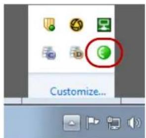
EUCON icon in the notification area

(Macintosh) Click the EUCON icon in the dock, and then select Window > EuControl Settings.
The EuControl Settings dialog box opens.
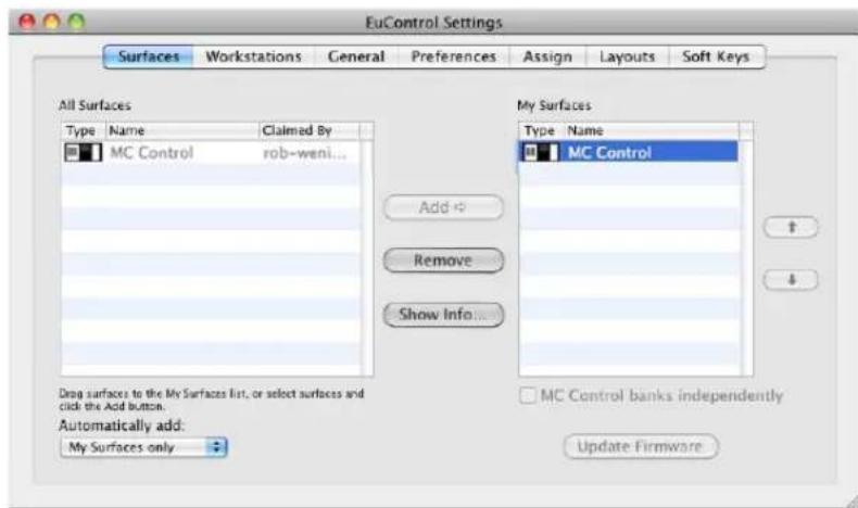
b. Click the Surfaces tab, and then click Update Firmware.
If there is updated firmware for your Artist Series controller, EuControl automatically downloads it.
c. Follow the on-screen instructions to install the new firmware.
-
Shut down your system.
-
Connect your Artist Series controller. For information on setting up your Artist Series controller, see the documentation that came with your equipment.
Configuring Avid Artist Series Controller Settings
You use the Controller Settings dialog box to configure your Avid editing application so that it can communicate with your Artist Series controllers.
To configure your Avid editing application for an Artist Series controller:
- Double-click Controller Settings in the Settings list of the Project window. The Controller Settings dialog box opens.
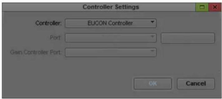
- Select Controller > EUCON Controller.
- Click OK.
Configuring Ethernet Connections (Macintosh)
You can connect your Artist Series controller to either the Ethernet 1 or Ethernet 2 port on your Macintosh system. By default, the EuControl application is configured to use Ethernet 1. You might need to change this configuration if your system connects to a corporate network or if it is part of a shared storage environment — for example, if you connect your Macintosh system to an Avid ISIS system.
The following procedure describes how to configure your network connections if you need to reserve one Ethernet port for a network or shared storage connection. You can use either Ethernet port for your Artist Series controller, but you should set the network priority for your network or storage connection higher than the priority for your Artist Series controller.
To configure Ethernet ports on a Macintosh system:
- Connect your Artist Series controller to either the Ethernet 1 or Ethernet 2 port on your Macintosh system.
- Select the Apple menu > System Preferences.
- In the Other area, click Euphonix.
The Euphonix dialog box opens.

- Click the Network Interfaces menu and select either Ethernet 1 or Ethernet 2, depending on which Ethernet port you want to use for your Artist Series controller.
- Close the Euphonix dialog box.
- Select the Apple menu > System Preferences.
- In the Internet & Wireless area, click Network.
The Network dialog box opens.
- Click the Action menu and select Set Service Order.
The Service Order dialog box opens.
-
If the Ethernet connection you want to use for your corporate network or shared storage connection is not at the top of the network connections list, select that Ethernet connection and drag it to the top of the list. For more information on setting the service order, see the Apple Help for your Macintosh system.
-
Click Apply, and then close the Network dialog box.
Setting the IP Address
Avid Artist Series controllers typically use Dynamic Host Configuration Protocol (DHCP) to obtain its IP address, usually from a router. The controllers revert to link-local addressing to generate an IP address if a DHCP server is not found on the network — for example, when you
connect a controller to a system using an Ethernet cable. You can override these methods of obtaining IP addresses by supplying a static IP address, which the devices use in all cases when turned on.

Avid does not recommend setting up static IP addresses unless you have experience in configuring network properties.
To set a static IP address (Avid Artist Control):
- Press and hold the Page Left and Page Right keys while you press and release the Power button.
The Network Setup screen appears on the Touchscreen.
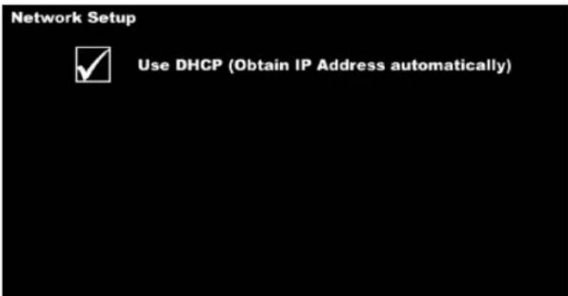
- Touch Use DHCP (Obtain IP Address automatically).
The parameter is deselected, and the Touchscreen displays the IP Address and Subnet Mask fields.
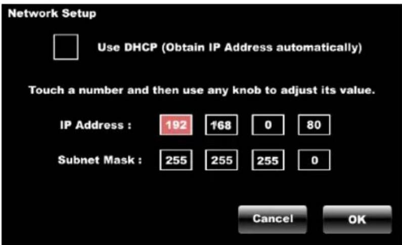
- Touch the first box of the IP Address field to select it, and then adjust its value by turning any of the eight knobs or the Jog wheel.
- Repeat the previous step to adjust all values of the IP Address and the Subnet Mask fields.
- Touch OK to save this static IP address. Turn off the controller and then turn it on to use the new IP address.
You can touch Cancel at any time to discard changes made to the IP address.
To set a static IP address (Avid Artist Transport):
- Press and hold the two soft keys on the left while you press and release the Power button. Hold down the soft keys until the Use DHCP screen appears in the display.
- Turn the Jog wheel clockwise to change the Use DHCP value from yes (default) to no.
You can use the + (plus) and - (minus) keys instead of the Jog wheel to decrease or increase the value, respectively.
- Press the Enter key to move the cursor to the next screen.

- Do one of the following:
▶Use the Jog wheel to set the value of the IP Address field.
▶Press the + (plus) key or the – (minus) key on the numeric keypad to increment or decrement the value. You can also use the numeric keypad to enter the number directly.
- Repeat step 3 and step 4 to adjust all values of the IP Address and the Subnet Mask fields.
You can press the Enter key to move the cursor forward until the first screen reappears to change a parameter to a different value.
- Press the two soft keys on the left at the same time to save this static IP address. Turn off the controller and then turn it on to use the new IP address.
You can discard changes made to the IP address at any time by turning off the controller before saving your changes.
To set a static IP address (Avid Artist Mix):
- Press and hold the Page Left and Page Right keys while you press and release the Power button.
The Use DHCP screen appears in the channel display for fader strip 1.
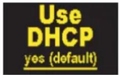
- Turn the knob underneath the display clockwise to change the Use DHCP value from yes (default) to no.
You can use the SEL and ON keys instead of the knob to decrease or increase the value, respectively.
- Press the Page Right key or the Top key to move the cursor to the next screen.
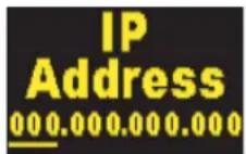
- Use the knob to set the value of the IP Address field.
- Repeat step 3 and step 4 to adjust all values of the IP Address and the Subnet Mask fields.
You can press the Page Left key to move the cursor back to the previous field or screen to change a parameter to a different value.
- Press the Page Left and Page Right keys at the same time to save this static IP address. Turn off the controller and then turn it on to use the new IP address.
You can discard changes made to the IP address at any time by turning off the controller before saving your changes.
Configuring EuControl Settings
Before you can use an Artist Series controller with your Avid editing application, you must configure the EuControl settings. You can connect your Artist Series controller to the EuControl application on your system so you can use it as a controller, connect additional workstations so they can access the controllers, and assign functions to buttons and keys on the Artist Series controller.
The EuControl application starts when you start your computer and runs in the background. Avid recommends that you make sure EuControl is running before you start your Avid editing application.
For a full description of configuration procedures and options, see the documentation that came with your Artist Series controller.
To connect an Artist Series controller to your system:
- Connect your Artist Series controller to your system and turn on the power for the device.
- Start your Avid editing application.
- Do one of the following:
▶ (Windows) Double-click the EUCON icon in the notification area.

EUCON icon in the notification area

(Macintosh) Click the EUCON icon in the dock, and then select Window > EuControl Settings.
EuControl Settings application opens. The All Surfaces list displays all available Artist Series controllers.
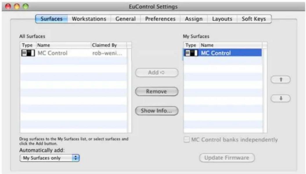
- Click the Automatically add: menu, and select one of the following:
To add all controllers listed in the All Surfaces list — which lists all devices available on your subnet — select All Surfaces. This setting is useful when you are the only person running EuControl on your network.
To add only those controllers listed in the My Surfaces, select My Surfaces Only. Since only one user at a time can control a surface, this avoids claiming surfaces needed by other users on your network.
The selected devices are connected to EuControl.
- (Option) If you select My Surfaces Only and you want to specify additional controllers to connect to your EuControl application, select a controller in the All Surfaces list, and then click Add.
The controller appears in the My Surfaces list. You can rearrange the order of the controllers using the up and down arrows, and you can remove controllers from the list using the Remove button. You can also rename the controller, which allows you to easily identify multiple controllers in the My Surfaces list.
- Click the Workstation tab.
The Workstations tab opens. The All Workstations list displays all systems on your subnet that have been configured for access to the available Artist Series controllers.

- (Option) If you want more than one workstation to access your Artist Series controllers, do the following:
a. Select the workstation in the All Workstations list and click Add.
b. Select the workstation in the My Workstations list and click Attach.
A check mark appears in the Attached column in the My Workstations list. The workstation can now access the Artist Series controllers connected to EuControl.
- Close the EuControl Settings application.
Artist Series Controller Button Mappings
When EuControl opens for the first time, it includes a set of default Avid editing functions mapped to the Artist Series controller buttons (the default mappings are called the “application set”). For a full list of the default application sets used with Avid editing applications, see “Controller Application Sets” on page 910. To modify the button mappings, see “Customizing Avid Artist Series Controls” on page 902.
The Soft Keys tab controls Surface, Wheel, and Touchscreen soft key assignments. With Artist Series controllers that include a Touchscreen, you can access the Surface soft keys with the circular buttons below the Touchscreen, and you can access the Touchscreen soft keys with the Soft Keys Setup Touchscreen.

The mappings included in the Soft Keys tab apply only to Artist Control and Artist Transport.
Artist Control and Artist Transport can control multiple applications, each with its own soft key assignments. Since the EuControl application responds dynamically as you move between applications, soft key assignments might change in the Soft Keys tab as the active application changes. Changing the focus to the desired application and then to the EuControl application restores the current assignments. You can save your soft key assignments at any time while using EUCON.

Be sure to check that the proper application is active before you click Save, Restore, or Revert.
The Soft Keys tab displays the name of the active application above the option menus and the soft key assignments.

EuControl Settings: active application, option menus, soft key display buttons
The default EuControl button mappings include the following:
- Surface — The Surface keys control the functions assigned to the 12 buttons located below the Touchscreen on Artist Control. The Surface section organizes the buttons in 6 pages. You can click the Page menu to select a different set of commands.
- Touchscreen — The Touchscreen keys control the keys displayed on the Soft Keys Setup Touchscreen on Artist Control. The Touchscreen section organizes the buttons in 6 pages.
- Wheel — The Wheel keys control the keys displayed above the Jog and Shuttle wheels on the Artist Control and Artist Transport.
Customizing Avid Artist Series Controls
You can modify the default Soft Key functions of the controls on your Artist Series controller by mapping them to buttons and keyboard shortcuts in your Avid editing application. You can also add custom key sequences, EUCON commands, pages to the surface controls or the touchscreen, and jog and shuttle wheel functions for some devices.
The following procedure provides a generic description of how to customize your controller. For a full description of the customizations available, see the documentation that came with your Artist Series controller.
To change a function in the Artist Series controls:
- In the EuControl application, click the Soft Keys tab.
- Click the Section menu, and select one of the following:
- Surface
- Touchscreen
- N u m p a d
The Soft Keys tab displays the existing controls for the selected section.
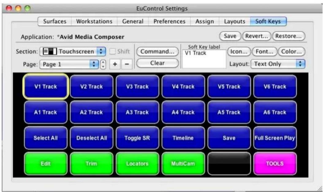
The Artist Transport controls for the Touchscreen.
- Do one of the following:
▶Select a button whose function you want to customize, and click Command.
▶Double-click a button whose function you want to customize.
The Soft Key Command Editor opens.

- Specify the action you want to associate with the control button.
The Soft Key Command Editor organizes the default commands as they appear in the Command palette or in menus.
- Close the Soft Key Command Editor.
The Soft Key tab updates and displays the new function.
- Click Save.
- Close the EuControl Settings application.
To add a function to the Artist Series controls:
- In the EuControl application, click the Soft Keys tab.
- Click the Section menu, and select one of the following:
- Surface
- Touchscreen
- N u m p a d
The Soft Keys tab displays the existing controls for the selected section.

The Artist Transport controls for the Touchscreen.
- If the display does not include any blank keys, click the Page menu and select a new page. You can also click the Add button to add a new page.
- Do one of the following:
▶Select a blank key and click Command.
▶Double-click a blank key.
The Soft Key Command Editor dialog opens.
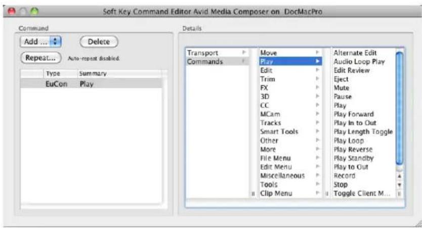
- Click Add and select one of the following:
- Key
- EuCon
- P a g e
- MC
-
Wheel
-
In the Details column, select the function you want to associate with the new soft key.
EUCON commands automatically label the button but do not select an icon.
- Close the Soft Key Command Editor.
The Soft Key tab updates and displays the new function.
Moving Through Footage with Artist Series Controllers
You can use your Artist Series controller to control how you move through footage. Depending on the functions available on your controller and the default and customizable controls, you can use the following methods:
- The Jog wheel allows for frame-by-frame positioning, depending on how fast you turn the wheel right (clockwise) or left (counterclockwise). Use the Jog wheel when you want to locate a specific frame by slowly viewing footage.

You can modify the sensitivity of the Jog wheel and the Shuttle ring by adjusting parameters in the EuControl application — for example, you can set the Jog wheel to step through your footage frame by frame. For more information, see the user's guide that came with your controller:
- The Shuttle ring alters the speed of playback by how far you turn the ring. The more you turn the ring to the right, the faster the footage moves forward. To move the footage in reverse, turn the ring to the left of the midpoint position. When held in position, footage continues to moves at a fixed rate. When you release the Shuttle ring, it automatically returns to its center position and footage stops changing. Use the Shuttle ring when you want to quickly scan footage.
- The Transport Controls allow you to play, pause, rewind, and fast forward in your sequence.
-
You can use the Rewind, Pause, and Fast Forward keys on your Artist Series controller to move through your footage as you do with J-K-L play in your Avid editing application. For more information on using the J-K-L keys, see “Playing Footage with the J-K-L Keys (Three-Button Play)” in the Help.
-
The track selection buttons on your Artist Series controller allow you to select and deselect tracks in the Timeline. Selecting tracks in the Timeline or in the Audio Mixer tool updates the track selection display in your Artist Series controller.
- You can solo and mute tracks on your Artist Series controller to isolate tracks as you monitor the audio playback. Using the solo and mute buttons on your Artist Series controller automatically updates the display in the Track Control panel and the Audio Mixer tool in your Avid editing application. You can use these buttons during playback.
Some commands only apply to specific windows in your Avid editing application. You might need to click the appropriate window — for example, the Timeline — before you can perform a specific function. For more information on moving through footage, see the documentation that came with your Artist Series controller.
Volume Automation and Pan on Artist Series Controllers
Some Artist Series controllers provide fader strips, each with a touch-sensitive fader, that control audio tracks for recording gain. Faders control assigned tracks and reflect changes made in the audio track properties, such as volume automation. Some Artist Series controllers also provide pan soft knobs that control audio tracks for recording pan automation. Pan soft knobs control assigned tracks and reflect changes made in the audio track pan values.
You can use the features available in the Audio Mixer tool to group faders on the Artist Series controller. When the faders for two or more tracks are grouped, the fader sends identical volume or pan messages for the tracks when you move one fader. This can be useful when you want to adjust audio on multiple tracks.
For information on grouping faders, see “Adjusting Clip Volume and Pan for Audio Tracks” on page 798.
Some Artist Series controllers include an On key, which indicates that a specified track is unmuted. Deselecting the On key mutes the track and changes the Mute button in your Avid editing application to orange for the specified track.

A second On button is located next to the faders on Artist Mix controllers. This button currently is not used.
You can also use the Bank and Nudge keys available on some Artist Series controllers to change the track assignments of the faders on the controller if the number of tracks you want to automate gain or pan on exceeds the number of faders on the controller. The Bank button changes track
assignments by the number of available faders — for example, shifting assignments from tracks 1 – 8 to tracks 9 – 16. The Nudge button changes track assignments by one track — for example, shifting assignments from tracks 1 – 8 to tracks 2 – 9.
Artist Mix provides buttons and indicator lights mapped to standard audio editing functions:
Button Function
SEL Controls and indicates pan recording.
SOLO Controls and indicates when a track is set to solo.
ON Controls and indicates when a track is unmuted or muted. The indicator is on when the track is not muted.
REC N Controls and indicates volume automation recording. The track display indicates the automation state by either an R (Read) or a W (Write).
Shift + REC/AUTO Controls and indicates automation mode. Latch mode (the default) is indicated by an unlit LED button; touch mode is indicated by a lit LED.
SEL Y Controls and indicates if a track is selected or deselected.
Once you record your gain or pan automation, you can use the Artist Mix or the Artist Control to modify gain or pan values on any audio keyframe selected in the Timeline.

You can disable the faders on your controller by pressing the Shift button and then pressing the Solo button on the left of the control surface. You might find this useful when you do not need to use the faders and you switch between the Source and Record monitors or the Source and Record views in the Timeline. To enable the faders, press the Shift button and the Solo button again.
Recording Volume Automation and Pan with Artist Series Controllers
If you record your automation in unlatched mode, releasing the fader returns the gain or pan values to the original values of the audio in your sequence. For information on enabling latch mode, see “Using the Latch Mode Feature on Artist Series Controllers” on page 909.
To record volume automation and pan information using an Artist Series controller:
- Select Tools > Audio Mixer.
The Audio Mixer tool opens.
-
(Optional) Click the Audio Mixer mode button and cycle through the Audio Mixer mode settings to the mode you want to select.
-
Attach the Artist Series controller to your system. (See "Configuring Avid Artist Series Controller Settings" on page 892.)
The position indicator lights in the Audio Mixer tool change to blue when the fader controller or mixer is on and correctly attached to the system.
Position indicator lights
- Click the Timeline Fast Menu button and select Audio Data > Auto Gain or Audio Data > Audio Pan.
- Move the blue position indicator to the section of audio that you want to adjust and mark In to Out points.
- Set Preroll and Postroll values, if necessary.
- Click the Record button to start recording your actions.
- Listen to the audio and adjust the slider or the pan control on the Artist Series controller for the track.
The system displays the slider values for the corresponding track in the Audio Mixer tool as you adjust the gain or pan.
- Click the Record button again to stop recording.

- Click the Audio Loop Play button to play the clip and test your results.
- To decrease the number of keyframes, click the Audio Mixer Tool Fast Menu button, and select Filter Volume Automation on Track — In/Out or Filter Pan on Track — In/Out. (Click the Track Selection button for a track to enable Filter Automation.)
- (Option) If you delete too many keyframes, use the Undo command to restore them.
- Repeat step 11 until you have decreased the number of keyframes to an acceptable level.
You should remove as many excess keyframes as possible while still maintaining the pan or gain changes.
To change the tracks assigned to faders on the Artist Series controller, do one of the following:
To move the track assignments to the left or right by the number of available faders, click the Bank Left or Bank Right button.
To move the track assignments to the left or right by one track, click the Nudge Left or Nudge Right button.
Using the Latch Mode Feature on Artist Series Controllers
Some Artist Series controllers have an Auto REC button for each track that lets you enable or disable latch mode for recording volume automation and pan information.
When a track is not in latch mode (sometimes called “touch mode”), it automatically stops recording as soon as you release it. When you release the fader, it begins moving again as it follows the volume information in the Timeline.
If you enable latch mode, the controller continues to record gain and pan after you release the fader or pan knob, with the gain and pan values remaining at the last values set during your recording session.
To use latch mode:
- Click the Auto REC button for the appropriate tracks on the controller.
You can click the button before or during a recording session.
- Set In and Out points, and click the Record button in the Audio Mixer tool.
The system begins playing the section and the faders move accordingly.
- When you want to make an adjustment, move the fader or pan soft knob to change the volume.
The system immediately begins recording.
- When you are finished adjusting the section, release the fader or pan soft knob.
When the track is in latch mode, the system continues to record audio volume information after you release the fader or soft knob.
- (Option) Press the Auto REC button to stop recording and snap the button back to its current Timeline position.
Using the Artist Series Controller for Editing Media
You can use your Artist Series controller to perform some of the basic editing functions available in your Avid editing application, including the following:
• Mark In and Out points
- Splice in and Overwrite edits
- Lift and Extract edits
• Tr i m e d i t s - Multicamera edits
These functions allow you to edit and trim clips in your sequences using the controller rather than the buttons and tools in your Avid editing application. For example, you can use the Jog wheel to navigate to a transition in the Timeline, and then you can use the Soft Key functions to activate Trim mode, and then perform a single- or dual-roller trim.
Some editing commands only apply to specific windows in your Avid editing application. You might need to click the appropriate window — for example, the Timeline — before you can perform a specific function.
Some editing functions are mapped to your Artist Series controller by default. If you want to access other editing functions, you can customize the controls by mapping other functions to the soft keys or Touchscreen on your controller. For more information, see “Customizing Avid Artist Series Controls” on page 902.
Controller Application Sets
The following sections include a list of the default key assignments (called an application set) for the Avid Artist Series controllers when used with an Avid editing application. You can customize the key assignments for your controller by using the EuControl application and save your customizations in a separate application set. For more information, see the user's guide that came with your Avid Artist controller. You can find PDF versions of the user's guide on the EuControl installation DVD that came with your product.
- Avid Artist Control
- Avid Artist Transport
• Installing EuControl Software
Avid Artist Control
The following table lists the default application set for Avid Artist Control when used with your Avid editing application.

Not all hardware and software versions support all of the functionality listed in this section. Some buttons might be unavailable on your controller.

Avid Artist Control: A — Solo/On track keys, Soft knobs, Rec/Sel keys, Fader strips, Soft key navigation, Shift key; B — Display, Soft keys; C — Soft knobs, Volume/Power, Transport navigation, Transport keys and jog wheel, Shift key
| Control | Function |
| Solo button | Solos the selected track. |
| On button | Unmutes and mutes the selected track. |
| Soft knobs | Eight continuously rotating knobs allowing you to adjust parameters such as pan levels. The knob has a built-in switch allowing it to be pressed from the top. The Touchscreen displays the current functions of the knobs. |
| Rec | Enables the selected track for recording. |
| Rec+Shift (Auto) | Changes the automation mode for a track. Press Rec+Shift to cycle through the automation modes (the Touchscreen displays the selected automation mode). |
| Sel | Selects an audio track. |
| Sel+Shift (Assign) | Opens the EuControl Settings dialog box and displays the Assign tab. |
| Fader strips | Allow you to adjust parameters while recording volume automation or pan. Press the Shift key and touch a fader to set it to unity gain. |
| Soft key navigation | Moves through the pages listing soft key functions in the display. Press Shift+up arrow (Home) or Shift+down arrow (End) to go to the first or last page. |
| Display | Displays functional information and controls, including the knob functions, Touchscreen controls, soft key labels. |
Control Function
Soft keys Provide editing and navigation functions specified in the soft key pages in the display. Moving through the soft key pages with the soft key navigation buttons changes the functions assigned to the soft keys.
Volume Adjusts the volume.
Power Turns the controller on or off.
Back Moves the knob set functions up one level if the knob set in the display is a submenu.
Top Moves the knob set functions to the topmost level if the knob set in the display is a submenu.
Application Switches between the most recently used open applications. Press and hold the Bank (left or right) button to cycle among all open applications.
Workstation (Shift+Application) Allows you to change the active workstation if you have more than one system attached to your controller. For information on attaching multiple workstations, see the documentation that came with your Artist Series controller.
Page (left and right) Changes the knob set functions by one page.
Cfg (Shift+Page left and right) Opens a knob set configuration page if available.
Nudge (left and right) Moves the set of four tracks assigned to the faders one track to the left or right — for example, if the faders are assigned to tracks 5 - 8, pressing the Nudge Left button changes the assignments to tracks 4 - 7.
Bank (left and right) Moves the set of four tracks assigned to the faders four tracks to the left or right — for example, if the faders are assigned to tracks 5 - 8, pressing the Bank Left button changes the assignments to tracks 1 - 4.
Mixer (Shift+Nudge Opens the Audio Mixer tool. Left)
Close (Shift+Nudge Right) Closes the active dialog box or tool.
Home (Shift+Bank Left) Moves the set of four tracks assigned to the faders to tracks 1 - 4.
End (Shift+Bank Right) Moves the set of four tracks assigned to the faders to the last bank of four faders.
Zoom Horz Allows you to use the Jog wheel to zoom horizontally in the Timeline.
Control Function
| Zoom Vert(Shift+Zoom Horz) | Allows you to use the Jog wheel to zoom vertically in the Timeline. |
| Jog Allows you to use the Jog wheel to jog through media in the Timeline or a monitor. | |
| Shuttle (Shift+Jog) Allows you to use the Jog wheel to adjust playback. You can alter the speed of playback depending on how far you turn the Jog wheel. | |
| Rew Moves to the previous transition in the sequence. | |
| FF Moves to the next transition in the sequence. | |
| Stop Stops playback. | |
| Play Starts playback. | |
| Rec Starts recording at the present location. Recording can use all active tracks. | |
| Jog wheel Turn the wheel to move through media in the Timeline or monitor (jog) or adjust playback speed (shuttle). | |
Avid Artist Transport
The following table lists the default application set for Avid Artist Transport when used with your Avid editing application.

Not all hardware and software versions support all of the functionality listed in this section. Some buttons might be unavailable on your controller.

Avid Artist Transport: Display, Soft keys, Numeric keypad (Show/Redo/Undo), Transport keys, Application change key, Shift key
Control Function
Display Displays functional information including timecode, active application, and soft key labels.
Soft keys Provide editing and navigation functions specified in the soft key pages in the application set. You can view the soft key functions by pressing the Show button.
The default soft key assignments for your Avid editing application, from left to right, include the following (Shift+soft key functions are listed in parentheses):
- Jog (Horizontal Zoom)
- Shuttle (Vertical Zoom)
- Splice-in (Toggle Source/Record)
• Overwrite (Timeline) - Go to Start (Lift)
- Undo (Extract)
Show Opens the EuControl application and displays the Soft Keys tab.
Control Function
| Show+soft key Shows the label for the selected soft key in the display. You can lock the Show key by pressing the key and then quickly pressing a soft key. Press the Show key again to unlock it. | |
| Redo (Shift+period) Redoes the last undone edit. | |
| Undo (Shift+asterisk) Undoes the previous edit. | |
| Transport keys Allow you to perform navigation and editing functions specified in the application set.The default Transport key assignments for your Avid editing application, from left to right, include the following (Shift+Transport key functions are listed in parentheses):Mark In (Trim Left 1 Frame)Previous Edit (Previous Edit)Reverse Play (Trim A Side)Stop (Trim Mode)Forward Play (Trim B Side)Next Edit (Next Edit)Mark Out (Trim Right 1 Frame) | |
| Application Switches between the two most recently used open applications. Press and hold the Application button while turning the Jog wheel in either direction to cycle among all open applications. | |
| Workstation(Shift+Application) | Allows you to change the active workstation if you have more than one system attached to your controller. For information on attaching multiple workstations, see the documentation that came with your Artist Series controller. |
Avid Artist Mix
The following table lists the default application set for Avid Artist Mix when used with your Avid editing application.

Avid Artist Mix: Display, Knob Set navigation, Sel/On keys and touch-sensitive knobs, Solo/On keys, Fader navigation, Knob Set selections, Fader strips, Shift key, Shift key
| Control | Function |
| Display | Displays functional information including timecode, active application, and soft key labels. |
| Back | Moves the knob set functions up one level if the knob set in the display is a submenu. |
| Top | Moves the knob set functions to the topmost level if the knob set in the display is a submenu. |
| Page (left and right) | Changes the knob set functions by one page. |
| Cfg (Shift+Page left and right) | Opens a knob set configuration page if available. |
| Sel | Changes the knob function or switches a secondary function's value. |
| On | Switches two-state parameters, such as EQ Band 1 on/off. |
| Soft knobs | Eight continuously rotating knobs allowing you to adjust parameters such as pan levels. The knob has a built-in switch allowing it to be pressed from the top. The Touchscreen displays the current functions of the knobs. |
Control
Function
Solo button Solos the selected track.
On button Unmutes and mutes the selected track.
Chan Enables channel mode.
Flip (Shift+Chan) Switches control between the fader controls to the knobs. A vertical double arrow appears in the display when the faders and knobs are flipped.
Insert Allows you to select the plug-in effect listed in the display. Press the soft knob for a track to select the plug-in.
Input (Shift+Input) Displays the Input knob set to configure input routing, mic gains, phantom power, and other application-specific parameters when pressed.
EQ Allows you to adjust a track's EQ parameters.
Dyn (Shift+EQ) Displays the Dynamics knob set to configure compressors, limiters, expanders, and gates when pressed.
Aux Assign a track's first aux send to a soft knob.
Group (Shift+Aux) Displays the Group knob set to configure group bus routing or control group (VCA) membership.
Pan Enables selected channels for pan control using the soft knob.
Mix (Shift+Pan) Displays the Mix knob set to configure output routing.
Fader strips Allow you to adjust parameters while recording volume automation or pan. Press the Shift key and touch a fader to set it to unity gain.
21 Using Audio Plug-Ins
This chapter describes how to access and use the audio plug-ins, including the Real-Time AudioSuite (RTAS) and AudioSuite plug-ins that come with your Avid editing application.
• Real-Time AudioSuite Plug-Ins
- Avid AudioSuite Plug-Ins
- Core Avid Audio Plug-Ins
Real-Time AudioSuite Plug-Ins
Your Avid editing application supports up to five RTAS plug-in inserts on each audio track. RTAS plug-ins are audio effects that you apply (or insert) on tracks, rather than on segments within your sequence. These inserts let you process audio material on a track in real time so that you can apply the effects to a sequence and play them back or output them without rendering them first. This lets you add a type of audio track effect that Avid Pro Tools ^® also supports.
When you use more than one plug-in on a track, your Avid editing application processes them in a series. Each effect gets added to that of any previous effect (moving from left to right in the Track Control panel). You can only apply mono RTAS plug-ins to mono audio tracks and stereo plug-ins to stereo audio tracks.
Avid qualifies a number of RTAS plug-ins manufactured by Avid for use with the current version of your Avid editing application. This includes RTAS plug-ins in the DigiRack and Bomb Factory plug-ins series. For a description of available RTAS plug-ins, see “Avid AudioSuite Plug-Ins” on page 925.
Avid also supports some plug-ins from third-party vendors that you can purchase separately. These plug-ins have their own detailed documentation. For information on Avid and third-party plug-ins, go to the Avid Web site at www.avid.com.
If you move your sequence from one Avid editing application to another system and the RTAS plug-in is not installed on that system, information about the effects display. In addition to the “Unavailable Effect” text, the effect name and other information displays which allows you to identify the effect. The information is displayed in the RTAS Tool.
Inserting an RTAS Plug-In on a Track in the Timeline
You can insert up to five RTAS plug-in track effects (inserts a through e) on an audio track. When you insert a plug-in effect to a track, you select the track where you want to apply the effect, which insert location you want to use on the track, and the specific effect you want to add to your sequence.
You can also insert an RTAS plug-in track effect by dragging an RTAS effect template from a bin to your sequence. For more information, see “Using RTAS Effect Templates” on page 924.
To insert an RTAS plug-in from the Timeline, do the following:
Right-click the Record Track button or the Track Control panel for the track where you want to apply the insert and select RTAS Effects [track number] > Insert [a-e] > [insert].
The plug-in effect is inserted in the track.
To insert an RTAS plug-in using the RTAS insert button, do the following:
- Click an RTAS insert button in the Track Control panel for the track where you want to apply the insert.
The RTAS tool opens.

- Click the Select Effect button, and select an RTAS plug-in effect:
The plug-in effect is inserted in the track.
To insert an RTAS plug-in using the Effect Palette:
- In the Project window, click the Effects tab.
The Effect Palette appears.

- Click an RTAS effect category, select the RTAS effect you want, and drag it to the segment or to the RTAS insert button where you want to apply the insert. You can only insert mono effects on a mono track, stereo effects on a stereo track, and surround sound effects on a surround sound track.
The Select Insert dialog box opens.
![Avid Media Composer Add an audio insert to track A1 Select insert: 1 - [Empty] 2 - [Empty] 3 - [Empty] 4 - [Empty] 5 - [Empty] Cancel](/content/2026/05/883817/images/4f09bdb868a2446126923d0597cd0cc384d673b3616a6300d86b864a5766ddef.jpg)
- Do one of the following:
▶ If you want to add a new insert, click an [Empty] insert button.
▶If you want to replace an existing insert, click the appropriate insert button.
The plug-in effect is inserted in the track to which you dragged the effect icon.
Editing an RTAS Plug-In on a Track in the Timeline
After you insert an RTAS plug-in on an audio track, you can access the plug-in controls by using the Track Control panel or the RTAS tool. When you select an RTAS insert button in the Track Control panel or an effect in the RTAS tool, the controls for the plug-in appear in the RTAS tool window.

RTAS plug-inserts in the Track Control panel

RTAS tool: Select Track, Select Insert, and Select Effect buttons (left), Bypass button (center), and Save Effect button (right)
You can modify the parameters of the effect as you play your sequence so you can hear how your modifications affect the sound of your audio.

If you have more than one insert on a track, you can dynamically change the plug-in controls that display in the RTAS tool as you play your sequence.
To edit an RTAS effect:
- If the Track Control panel is not visible, click the Track Control Panel button or click Timeline fast menu and select Track Control Panel.
- Click the RTAS insert button for the RTAS effect you want to edit.
If a plug-in is inserted on the track, the Select Effect button displays the name of the plug-in and the RTAS tool opens a window associated with the plug-in.

The Compressor/Limiter Dyn 3 plug-in window displayed in the RTAS tool dialog box.
You can also open the RTAS tool by selecting Tools > RTAS or right-clicking the Record Track button for the track where you want to edit an insert and selecting RTAS tool. You can use the buttons in the RTAS tool to select a specific insert to edit.
- (Option) If you want to change the plug-in effect for your insert, click the Select Effect button and select a new plug-in.
- Make any necessary adjustments to your effect.
If you play your sequence, you can modify the effect dynamically without stopping playback.
- (Option) If you have multiple inserts on a track, do one of the following to change the plug-in controls that display in the RTAS tool:
▶Click the Select Track or the Select Insert button and select a different insert.
▶ Press the arrow keys to cycle through the available inserts.
Up and down arrow keys change the selected track. Right and left arrow keys change the selected insert.
- (Option) Click the Bypass button if you want to play audio without processing the track effect. This lets you compare the audio with or without the plug-in effect.
If you click Ctrl+Bypass (Windows) or Cmd+Bypass (Macintosh), you can disable RTAS effects on all tracks in the Timeline.
The Bypass button and the RTAS insert buttons on the selected track change to blue.
Bypass
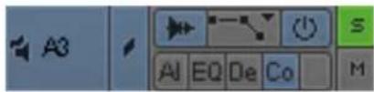
- To save your changes, do one of the following:

▶Click the Save Effect icon in the RTAS tool.
▶Close the RTAS tool.
Moving and Copying RTAS Inserts
You can move and copy RTAS inserts from one track to another. However, you can only move mono inserts to mono tracks and stereo inserts to stereo tracks.

RTAS plug-in effects on inserts a, b, and c in the Track Control panel
To move an RTAS insert from one position to another, do the following:
Click an RTAS insert button and drag it to an RTAS insert button on a new track or to a new insert button on the same track. If the destination RTAS button already has an insert on it, the new insert replaces the existing one.
To copy an RTAS insert from one position to another, do the following:
Alt+drag (Windows) or Option+drag (Macintosh) an insert button to an insert button on a new track or to a new insert button on the same track.
Ordering RTAS Inserts on a Track
When you combine RTAS plug-ins on an audio track, the order in which you insert them affects how your Avid editing application applies the effects. This can produce different results for your sequence. Your Avid editing application processes RTAS effects in order from left to right as they appear in the Track Control panel (insert a through insert e). For example, if you insert a compressor plug-in to the right of an EQ plug-in, your Avid editing application applies EQ effect first and then applies the compressor effect to the result.
You must have one empty insert on your audio track so you do not replace an existing insert when you reorder the inserts.
To modify the order of RTAS inserts on a track, do the following:
Click an RTAS insert button and drag it to an empty insert button in the Track Control panel.
Removing RTAS Inserts on a Track
Removing an insert deletes the effect from the track.
To remove an RTAS insert:
- Do one of the following:
▶Select Tools > RTAS.
Right-click the Record Track button for the track where you want to edit an insert and select RTAS tool.
▶Click the RTAS insert button for the RTAS effect.
The RTAS tool opens.
- Click the Select Track button and select the track where you want to delete an insert.
- Click the Select Insert button and select "no insert."
Your Avid editing application removes the insert from the track.
- Close the RTAS tool to save your changes.
Using RTAS Effect Templates
If you apply an RTAS track effect and make a set of adjustments to it, you can quickly recreate the same sound on other tracks in your sequence or project. You can save an RTAS effect with its parameter settings to a bin as an effect template. You can then apply the template to other audio tracks at any time.
You can apply an RTAS track effect template with all its parameters directly to an RTAS insert button in the Track Selection panel or to clips in the Timeline.
To save an RTAS effect as a template, do one of the following:

▶ Click the Save Effect button in the RTAS tool and drag it to a bin.
▶Click an RTAS button and drag it to a bin.
A new RTAS track effect template appears in the bin, containing the parameter setting information for the effect. The new RTAS effect template is identified in the bin by an effect icon. By default, your Avid editing application names the template by the plug-in name.
To apply an RTAS effect template to an audio track, do one of the following:
Drag the RTAS effect template from the bin to an RTAS insert button in the Track Selection panel.
Drag the RTAS effect template from the bin to a segment on the track where you want to apply the effect. The Select Insert dialog box opens so you can select the insert where you want to apply the effect.
The RTAS effect is applied to the track.
Avid AudioSuite Plug-Ins
Your Avid editing application supports AudioSuite, the Avid host-based, file-based plug-in specification. Users have access to mono and stereo audio-processing plug-ins developed by Avid and by Avid third-party developers. These plug-ins perform pitch modifications, artifact removal, audio reversal, and many other processes.
Avid qualifies a broad range of the AudioSuite plug-ins manufactured by Avid for use with the current version of your Avid editing application. This includes all AudioSuite plug-ins in the DigiRack and Bomb Factory plug-ins series.
Avid supports other AudioSuite plug-ins that do not install with your Avid editing application. You can use these plug-ins on a trial basis and then purchase them through Avid. These plug-ins have their own detailed documentation.
For information on Avid and third-party plug-ins, go to the Avid Web site at www.avid.com.
For information on plug-ins that are not supported by your Avid editing application, see “AudioSuite Plug-in Limitations” on page 935.
AudioSuite Plug-Ins Installation
The installer for your Avid editing application automatically creates a Plug-Ins folder that stores AudioSuite plugins in the following location:
(Windows) drive:\Program Files\Common Files\DSM\DAE
(Macintosh) Macintosh HD/Library/Application Support/DSM
Your Avid editing application automatically installs a set of core plug-ins. When you purchase additional plug-ins, the third-party vendor provides instructions on how to load the plug-ins.

Your Avid editing application requires the files in the Plug-Ins folder named AvidAppPlugIn.dpm and AvidAppPlugIn.dpm.rsr (Windows) or Avid_Application_PlugIn (Macintosh). Do not delete them.

AudioSuite Plug-ins supported by Avid appear in the Plug-In Selection menu in the AudioSuite window.
Using Avid AudioSuite Plug-Ins
You can use AudioSuite plug-ins in two ways.
- You can apply a plug-in to a clip in the Timeline and then create a rendered effect. For more information, see “Applying an AudioSuite Plug-in to a Clip in the Timeline” on page 926.
- You can use the controls in the AudioSuite window to create a new master clip. This method lets you process more than one channel at a time and to create new media with a duration longer or shorter than the source media. For more information, see “Creating New Master Clips with AudioSuite Plug-Ins” on page 929.
By default, the AudioSuite window displays the controls for applying a plug-in to a clip in the Timeline. When you drag a master clip into the window, the window expands to display additional parameters for working with master clips.
The AudioSuite tool automatically applies stereo plug-ins to stereo tracks and mono plug-ins to mono tracks.
Applying an AudioSuite Plug-in to a Clip in the Timeline
The following illustration shows the default layout of the AudioSuite window.


If you want to use plug-ins that operate on stereo pairs or that change the length of the audio clip, use the methods described in “Creating New Master Clips with AudioSuite Plug-Ins” on page 929.
To apply an AudioSuite plug-in to a clip in the Timeline:
- Open the AudioSuite window by doing one of the following:
▶Select Tools > AudioSuite.
If an audio tool is already open, click the Effect Mode Selector menu, and select AudioSuite.
- Use the Track Selection Menu button to select the tracks that you want to modify.
When you select an item from this menu, the system selects or deselects the corresponding track in the Timeline.
- (Option) To select multiple tracks, press the Shift key while you select additional tracks from the Track Selection menu.
Plus signs (+) mark the additional tracks and indicate that the effect is applied to more than one track.
- Click the Plug-In Selection menu, and select a plug-in.
Your Avid editing application automatically applies the plug-in effect to the track or tracks in the Timeline. It applies stereo effects to stereo tracks and mono effects to mono tracks.
- Click the Activate Current Plug-In button.
A dialog box associated with the plug-in opens.
- Make any necessary adjustments, and click the Preview button to preview the effect.
For more information, see “Common Buttons in the AudioSuite Plug-In Dialog Box” on page 927.
- To save the effect, click OK.
To close the dialog box without saving the effect, click Cancel.
- (Option) To save the effect as a template, drag the effect icon to a bin.
Common Buttons in the AudioSuite Plug-In Dialog Box
The contents of the plug-in dialog boxes vary, but the top six buttons are always visible. Buttons unavailable for a plug-in appear dimmed. The following illustration shows the Gain plug-in.

Common buttons in the AudioSuite Plug-In dialog box
The following table describes the six common buttons:
Button Description
OK Saves the effect and closes the dialog box.
Cancel Closes the dialog box and does not save the effect.
Preview Plays back a portion or all of the currently selected audio clip with processing.
Some plug-ins can preview in real time and some cannot. If a plug-in cannot preview in real time, your Avid editing application plays back the processed audio in 2-second intervals: it processes 2 seconds of audio, plays it, and repeats the operation.
Render Renders the effect and creates a new audio media file.
Bypass Plays the selected audio without processing. This is useful for comparing the audio with and without processing applied.
Find level Performs an analysis pass on the audio. Depending on the plug-in, the text and function of this button might change.
Some plug-ins require an analysis pass on the audio data before they can process the information. If so, they perform the first pass automatically. Other plug-ins do not require a first pass but can achieve more accurate results if you allow them to perform a first pass. The Find Level button is available only if the plug-in supports the optional pass.
AudioSuite Fast Menu
The AudioSuite Fast menu lets you do the following:
- Apply an existing AudioSuite template. See "Using AudioSuite Effect Templates" on page 934.
- Set, render, or remove AudioSuite plug-ins. The menu text differs, depending on whether you have In to Out points in the sequence.
The following commands appear in the menu:
Command Description
Global The segment has no In points. The command affects all the plug-ins on the enabled tracks.
IN/OUT The segment has In to Out points. The command affects the plug-ins on the enabled tracks within the marked region.
From IN The segment has an In point but no corresponding Out point. The command affects all plug-ins on enabled tracks, starting with the In point.
Rendering AudioSuite Plug-in Effects
You need to render all AudioSuite plug-ins before you can play back the effect. If you do not render the effect manually, your Avid editing application automatically renders the effect before it creates an audio mixdown or audio dissolve containing the effect.

When you render an audio effect on an AMA media clip, all audio media files are written as PCM (MXF), regardless of what you set for the audio file format.
For more information, see “Troubleshooting AudioSuite Plug-Ins” on page 935.
Creating New Master Clips with AudioSuite Plug-Ins
You can use AudioSuite plug-ins to create new master clips. This lets you use multiple input and output channels and to change the length of the media. You can perform the following operations on the media you create:
- Apply AudioSuite plug-ins to more than one track at the same time. For example, a plug-in might let you process two separate tracks as a stereo pair. This enables you to use plug-ins that perform linked compression, reverb, and other effects that allow multichannel input.
- Create new media with a longer or shorter duration than the source media. This lets you use effects that perform time compression and expansion. For example, you can use a Time Compression Expansion plug-in to change the length of the audio file, or you can lengthen the file in order to add a reverb trail.
- Apply one mono AudioSuite effect to multiple inputs of a master clip in a multiple-mono fashion.
AudioSuite Controls for Creating New Master Clips
When you drag a master clip onto the AudioSuite window, the window automatically expands to display additional controls. You can also click the Display/Hide Master Clip Controls button to display or hide the additional parameters.
The following illustration identifies the controls in the expanded AudioSuite window. For information on the controls in the top part of the window, see “Applying an AudioSuite Plug-in to a Clip in the Timeline” on page 926.

The following table describes the controls in the AudioSuite window.
Control Description
1 Clip Selection menu Lets you choose the active clip. It lists the current active clip and other clips you dragged into the AudioSuite window. The window controls change to reflect the active clip.
Control Description
| 2 Input Source Track selectors | Let you choose the input source tracks for the effect.The system automatically chooses a preview track and displays a blue Speaker icon on the track. To change the preview track, Alt+click (Windows) or Option+click (Macintosh) the appropriate source track. If the source track used as the current preview track is deselected, the system chooses the lowest available track.The track selection buttons do not reflect multichannel track grouping on master clips, so the selection buttons might differ from those in the Source monitor. |
| 3 Processing Mode Selection menu | Displays the current processing mode of the AudioSuite effect on a given clip. For more information, see “Mono, Stereo, and Multichannel Processing in AudioSuite Plug-Ins” on page 932. |
| 4 Target Bin for New Master Clip menu | Lets you choose the target bin. The system places the new media and a corresponding AudioSuite effect template in the bin. The template lets you modify the effect at a later time. |
| 5 Status display Provides information about the current state of the DAE (the software that manages the AudioSuite plug-ins) and the currently applied effect. For stereo and multichannel processing plug-ins, the Status display identifies the maximum number of tracks that the plug-in can process. If you initially select more than the maximum, the system automatically disables tracks until it reaches the plug-in’s maximum number.[6077] On the Macintosh, you can Command+click the status display to close the DAE. This might reclaim a small amount of system memory, especially if you have a large number of AudioSuite plug-ins installed. However, when you close the DAE in this way, the Status display changes to “Must relaunch application to reconnect to DAE,” and you cannot start the DAE again without quitting and reopening your Avid editing application. | |
| 6 Load Result check box When enabled, instructs the system to automatically load the resulting master clip into the Source monitor. | |
| 7 Handle Length for End of Master Clip (seconds) text box | Lets you add filler at the end of a master clip. The value represents the number of seconds to add. For example, use this feature to add filler at the end of a master clip when you use a reverb effect to add a reverb trail to the end of the clip. Select the value before you run the plug-in. |
| 8 Load In Source Monitor button | Loads the current source master clip into the Source monitor. You can use when you want to add or change In to Out points on the clip. |
| 9 Toggle Master Clip Mode button | Activates the master clip processing mode. The button displays as yellow when master clip processing mode is active. |
Control Description
| 10 Mark IN to OUT indicators | These lights change to green when a mark In or mark Out exists on the current master clip. |
| 11 Find Source From Effect button | Lets you find the master clip associated with an AudioSuite template. When you drop an AudioSuite effect template into the AudioSuite window, the system activates this button. Click the button to load the master clip into the AudioSuite window as the active master clip. |
| A template in the AudioSuite window must reference an existing master clip. |
Mono, Stereo, and Multichannel Processing in AudioSuite Plug-Ins
AudioSuite plug-ins let you select the following types of processing:
- Mono processing only — This option is available for plug-ins that operate on only one mono audio track at a time. The other option (Stereo) appears dimmed. The plug-in applies the effect to each source track individually, in a serial manner.
- Mono and stereo processing — These options are available for plug-ins that can operate on stereo tracks or that can treat two tracks as a stereo pair. This allows the system to apply the audio effect simultaneously to each track. For example, the Time Compression Expansion plug-in typically operates on a stereo pair. You can choose mono if you want the plug-in to operate on each track individually, in a serial manner.
- Mono and multichannel processing — These options are available for plug-ins that can process multiple channels or tracks simultaneously. For example, the Normalize plug-in lets you adjust the volume separately for each channel or track or to adjust the volume for all channels or tracks at the same time. In the latter case, the system examines all enabled channels and tracks for the loudest volume and then adjusts them relative to that value.
For mono processing and for stereo processing of stereo clips, the system creates a new master clip with the same number of tracks that you selected in the AudioSuite window.
For stereo and multichannel processing of mono audio clips, the plug-in creates a master clip with the number of tracks equal to the number of output tracks from the plug-in. For example, a plug-in that operates on stereo pairs creates a two-track master clip. A plug-in that operates on multiple tracks creates a master clip with the same number of tracks that were selected in the AudioSuite window.
The Status display at the bottom of the AudioSuite Plug-in window indicates how many tracks the plug-in can process. If you enable more tracks than it can be process, the plug-in automatically selects the correct number of tracks. You can change the track selection based on your needs.
Most AudioSuite plug-ins automatically select the appropriate processing mode and label the values in the Processing Mode Selection menu. For example, the Normalize plug-in offers two choices: Level On Each Chan-Track and Levels On All Chans-Tracks (default).
You select the processing mode from a menu in the AudioSuite window as described in the next section.
Using AudioSuite Plug-ins to Create New Master Clips
To create new master clips using the AudioSuite plug-ins:
- Drag one or more master clips or subclips into the AudioSuite window.
Your Avid editing application automatically enters Master Clip Processing mode and expands the AudioSuite window, if necessary. - If you dropped more than one master clip in the AudioSuite window, select a clip to work on from the Clip Selection menu.
- Select the input sources from the Input Source Track selectors.
- (Option) Alt+click (Windows) or Option+click (Macintosh) the Input Source Track selector to change the preview source track.
- (Option) Type a value in the Handle Length text box to lengthen the clip by a specific amount.
For example, type 2 if you plan to add a 2-second reverb trail.
If you are using Time Compression/Expansion plug-ins, the plug-ins automatically lengthen or shorten the clip.
-
Click the Plug-In Selection menu, and select a plug-in.
-
Click the Activate Current Plug-In button to open the plug-in's dialog box.
For more information, see “Common Buttons in the AudioSuite Plug-In Dialog Box” on page 927.
-
Make any changes, and click the Preview button to preview the effect.
-
Either render the plug-in from the Plug-In dialog box, or return to the AudioSuite window.
For more information on rendering, see “Rendering AudioSuite Plug-in Effects” on page 929.
When you click the Render Effect button, your Avid editing application creates a new master clip in the target bin. Your Avid editing application names the new master clip by combining the original clip name with the effect name, for example, Test Audio clip_Normalize (Windows) or QuietClip.Normalize (Macintosh).
Your Avid editing application also creates an AudioSuite effect template in the bin as described in “Using AudioSuite Effect Templates” on page 934.
Using AudioSuite Effect Templates
When you create a new master clip, your Avid editing application also creates an AudioSuite effect template in the bin. This effect template contains a reference to the original master clip to which you applied the effect.
Template names take the following format:
- (Windows) Your Avid editing application combines the original clip name with the effect name — for example, Test Audio clip - AudioSuite Plug-In Effect: Normalize.
- (Macintosh) Your Avid editing application adds an effect file name extension to the effect name — for example, QuietClip.NormalizeQuietClip.Normalize.effect.
You can use the template if you want to modify an effect on a clip.
To use a template to modify a master clip:
- Drag an AudioSuite plug-in template into the AudioSuite window.
The Find Source From Effect button becomes active.
- Click the Find Source From Effect button to load the master clip into the AudioSuite window.
If a corresponding master clip exists, the system loads the master clip with its associated plug-in values.
- Modify the effect as described in “AudioSuite Controls for Creating New Master Clips” on page 930.
To add a template to the AudioSuite Fast menu:
- Open the bin containing your AudioSuite templates.
- Select File > Open Bin.
A dialog box opens.
- Navigate to the AudioSuite Site bin file in the following location:
(Windows) drive:\Program Files\Avid\Avid editing application\
SupportingFiles\Site_Effects\Site_AudioSuite_Bin.avb
(Macintosh) Macintosh HD/Applications/Avid editing application/
SupportingFiles/Site_Effects/Site_AudioSuite_Bin
- Double-click the Site_AudioSuite_Bin file.
The Site_AudioSuite_Bin window opens.
- Drag one of your AudioSuite templates to the Site_AudioSuite_Bin window.
-
If you have not already done so, name the template by clicking the text and typing a name.
-
Close the bin.
Your Avid editing application does not save the effect to the bin until you close the bin.
- Click the AudioSuite Fast Menu button to locate your new template.
Using AudioSuite Plug-Ins in Stereo
You can use some AudioSuite plug-ins on either mono or stereo tracks.
To use AudioSuite plug-ins in stereo, be aware of the following:
- To process a mono track and obtain a stereo result, select the desired track or mark an In point and Out point, then either select an empty track or add an new one. When you process the audio, the result will be two tracks or regions that represent the right and left channels of the processed audio. You should then pan these tracks hard right and hard left in your mix.
- If you work with mono tracks and set a plug-in to Stereo mode, then select an odd number of tracks for processing, the plug-in processes the selected tracks in pairs to create the stereo effect. However, the last odd, unpaired track will be processed as mono, using the left channel settings of the stereo plug-in. If you want the last track to be processed in stereo, you must select an additional track to pair it with — an empty one, if necessary.
AudioSuite Plug-in Limitations
The following limitations apply to the AudioSuite plug-ins:
- Avid does not support some plug-ins that perform analysis passes on the audio data. This includes plug-ins that use playlist information to cache analysis data.
- If you want to use plug-ins that change the length of an audio clip or that operate on multiple inputs at the same time, use the method described in “Creating New Master Clips with AudioSuite Plug-Ins” on page 929. Applying an effect to a clip in the Timeline does not work for these operations.
Troubleshooting AudioSuite Plug-Ins
You might need to respond to an error message or cancel a render operation when rendering AudioSuite plug-ins. If the DAE is not running when you start to render an AudioSuite plug-in effect, the system displays an error message stating that the DAE connection does not exist.
To respond to error messages:
- Do one of the following:
▶ Select Cancel to stop the rendering process. This lets you open the AudioSuite tool and then start rendering again.
▶ Select Bypass to continue the rendering process. The plug-in effect does not render.
In most cases, you should click Cancel and open the AudioSuite window.
If you have not installed the plug-in when you go to render a plug-in effect, your Avid editing application displays an error message informing you which plug-in you must install. At that time, you can cancel or bypass the rendering process.
- To cancel a render operation, press Ctrl+period (Windows) or Command+period (Macintosh).
Be careful not to press these keys multiple times. If you press Ctrl+period (Windows) or Command+period (Macintosh) after the render operation stops from a previous Ctrl+period (Windows) or Command+period (Macintosh), your Avid editing application closes the window after it cancels the render operation.
Working with Dolby E Surround Sound Plug-ins
Dolby E is an audio coding technology created by Dolby Labs that compresses up to 8 channels of audio and metadata into 2 channels. You can capture or import media clips that include encoded Dolby E surround sound data, and you can then edit those clips in the Timeline. When you want to monitor tracks with Dolby E surround sound encoding, you can use supported third-party Dolby E plug-ins to decode the metadata. You can also encode Dolby E metadata in order to export surround sound media for use in your production environment.
For more information on capturing Dolby E media, see “Capturing Media with Dolby E Information” on page 263.
When you work with Dolby E encoder and decoder plug-ins, keep in mind the following:
- You can add an RTAS Dolby E decoder plug-in to a track to decode Dolby E data in the Timeline in real time. This allows you to easily monitor and edit the surround sound audio in your sequence.
- You can use an AudioSuite decoder plug-in to decode the Dolby E data on a clip, but you must use the plug-in to create a new master clip in master clip processing mode. (For information on creating master clips with plug-ins, see “Using AudioSuite Plug-ins to Create New Master Clips” on page 933.) Supported Dolby E decoder plug-ins decode the metadata and create separate mono audio clips in the bin, which you can then edit into your sequence or use the Modify dialog box to create a surround sound audio clip.
- When you use a Dolby E encoder plug-in to encode Dolby E data in an audio clip or a surround sound audio track in the Timeline, the plug-in creates a new media file in the specified location on your system. If you render the plug-in effect or create a mixdown of a sequence with a Dolby E encoder effect applied to it, you can no longer use the Dolby E metadata to monitor your audio because the effect has been rendered. Instead, you should encode the Dolby E data, creating a new media file on your system, and then remove the
Dolby E plug-in effect from your sequence. This allows you to continue to monitor and edit the surround sound audio. Alternately, you can leave the effect in the Timeline as long as you do not perform either a render or mixdown of the sequence.
For more information, see the documentation that came with your Dolby E plug-in.
Core Avid Audio Plug-Ins
A set of core audio plug-ins installs with your Avid editing application. RTAS and AudioSuite Plug-ins supported by Avid, such as the core set, appear in the RTAS tool and the AudioSuite Plug-in Selection menu with their plug-in name.

Other audio plug-ins might get installed on your system for use with Pro Tools, or you might download plug-ins. Avid does not recommend using unsupported plug-ins with Avid editing applications.
Avid supports other RTAS and AudioSuite plug-ins that do not install with your Avid editing application. You can use these plug-ins on a trial basis and then purchase them through Avid. These plug-ins have their own detailed documentation. For information on Avid and third-party plug-ins, go to the Avid Web site at www.avid.com.
The following table provides a brief description of each of the core plug-ins, with cross-references to more detailed information in the remaining topics in this section.
You can use RTAS track effect plug-ins on both mono and stereo tracks. You can use some AudioSuite plug-ins in either mono or stereo clips. For more information, see “Using AudioSuite Plug-Ins in Stereo” on page 935.
Audio Plug-ins
Plug-In Description
AIR Chorus Gives depth and space to the audio signal.by applying a short modulated delay. For more information, see “AIR Chorus (RTAS)” on page 941.
AIR Distortion Modifies the audio signal with various types of distortion. For more information, see “AIR Distortion (RTAS)” on page 941.
AIR Dynamic Delay Creates a delay line that can synchronize to the tempo of your audio sequence. For more information, see “AIR Dynamic Delay (RTAS)” on page 942.
AIR Enhancer Enhances the low and high broadband frequencies of the audio signal. For more information, see “AIR Enhancer (RTAS)” on page 944.
Audio Plug-ins
| Plug-In | Description |
| AIR Ensemble | Creates fluid, shimmering modulation effects. For more information, see “AIR Ensemble (RTAS)” on page 945. |
| AIR Filter Gate Breaks the audio signal into staccato rhythmic patterns with variable filtering, amplitude, and panning. For more information, see “AIR Filter Gate (RTAS)” on page 946. | |
| AIR Flanger | Applies a short modulating delay. For more information, see “AIR Flanger (RTAS)” on page 947. |
| AIR Frequency Shifter Shifts the audio signal's individual frequencies inharmonically. For more information, see “AIR Frequency Shifter (RTAS)” on page 949. | |
| AIR Fuzz-Wah Modifies the audio signal with different types and varying amounts of transistor-like distortion. For more information, see “AIR Fuzz-Wah (RTAS)” on page 950. | |
| AIR Kill EQ Removes the Low, Mid, or High broadband frequency range from an audio signal. For more information, see “AIR Kill EQ (RTAS)” on page 951. | |
| AIR Lo Fi Lets you bit-crush, down-sample, clip, rectify, and mangle the input signal. For more information, see “AIR Lo Fi (RTAS)” on page 951. | |
| AIR Multi-Chorus | Applies a thick, complex chorus effect to the audio signal. For more information, see “AIR Multi-Chorus (RTAS)” on page 954. |
| AIR Multi-Delay | Applies up to six delay lines to the audio signal. For more information, see “AIR Multi-Delay (RTAS)” on page 955. |
| AIR Non-Linear Reverb | Creates special gated or reversed reverb effects. For more information, see “AIR Non-Linear Reverb (RTAS)” on page 956. |
| AIR Phaser | Creates a unique sweeping sound by applying a phaser effect. For more information, see “AIR Phaser (RTAS)” on page 957. |
| AIR Reverb | Creates a sense of room or space by applying a reverb to the audio signal. For more information, see “AIR Reverb (RTAS)” on page 959. |
| AIR Spring Reverb | Creates a classic analog, spring reverb sound. For more information, see “AIR Spring Reverb (RTAS)” on page 961. |
| AIR Stereo Width | Lets you enhance the stereo presence for mono audio signals. For more information, see “AIR Stereo Width (RTAS)” on page 962. |
| AIR Talkbox | Adds voice-like resonances to audio signals. For more information, see “AIR Talkbox (RTAS)” on page 963. |
Audio Plug-ins
| Plug-In | Description |
| AIR Vintage Filter Applies a modulating, resonant filter to the audio signal. For more information, see “AIR Vintage Filter (RTAS)” on page 965. | |
| BF Essential Clip Remover | Repairs clipped audio recordings. For more information, see “BF Essential Clip Remover (AudioSuite)” on page 966. |
| Bomb Factory BF76 Provides compression modeled after the 1176 studio compressor. For more information, see “Bomb Factory BF76 (RTAS and AudioSuite)” on page 967. | |
| Chorus | Provides time-delay and pitch-shift effects, added to the clip to create a multi-layered sound. For more information, see “Chorus (AudioSuite)” on page 967. |
| Compressor/Limiter III | Applies either compression or limiting to audio material, depending on the ratio of compression used. For more information, see “Compressor/Limiter III — Dynamics III (RTAS and AudioSuite)” on page 968. |
| D-VerbTM | Provides a studio-quality reverberation or ambience processing to single or multiple tracks. For more information, see “D-Verb (RTAS and AudioSuite)” on page 972. |
| DC Offset Removal | Removes an audio artifact that is common in digital audio files. A DC offset is caused by poorly calibrated analog-to-digital converters (A/Ds), and can produce clicks and pops on clip edit transitions if not removed. For more information, see “DC Offset Removal (AudioSuite)” on page 973. |
| De-Esser III Reduces sibilants and other high frequency noises that can occur in vocals, voiceovers, and wind instruments such as flutes. For more information, see “DeEsser III — Dynamics III (RTAS and AudioSuite)” on page 973. | |
| Delay Provides time-delay-based effects. Effects obtained through the use of Delay include slap echo, doubling, chorusing, and flanging. For more information, see “Delay Plug-In (RTAS and AudioSuite)” on page 975. | |
| Duplicate Creates a new master clip from a selected audio clip. The plug-in uses the In and Out points on the selected clip to define the boundaries of the new clip. For more information, see “Duplicate (AudioSuite)” on page 976. | |
| EQ Lets you adjust frequency equalization on individual audio clips. Four EQ plug-ins are available: 1-Band EQ II, 4_Band EQ II, 1-Band EQ III, and 7-Band EQ III. For more information, see “EQ (AudioSuite)” on page 977. | |
| Expander/Gate III | Applies expansion or gating to audio material, depending on the ratio setting. For more information, see “Expander/Gate III — Dynamics III (RTAS and AudioSuite)” on page 982. |
| Flanger | Creates a flange effect that approximates a true tape-generated flange. For more information, see “Flanger (AudioSuite)” on page 984. |
Audio Plug-ins
| Plug-In | Description |
| Funk Logic Masterizer | Provides low-fidelity sound design capabilities for the creative degradation of audio. For more information, see “Funk Logic Masterizer (AudioSuite)” on page 985. |
| Gain Same as Normalize, but allows positive or negative gain adjustment. For more information, see “Gain (AudioSuite)” on page 985. | |
| Invert | Inverts the polarity (phase) of the audio file. For more information, see “Invert (AudioSuite)” on page 986. |
| Lo-Fi Processes audio by reducing its sample rate and bit resolution. For more information, see “Lo-Fi Plug-In (RTAS and AudioSuite)” on page 986. | |
| Multi-Tap Delay Lets you control up to four independent delays applied to the audio clip. For more information, see “Multi-Tap Delay (AudioSuite)” on page 988. | |
| Normalize Finds the peak value in the source audio file and scales the entire file proportionally to that maximum value. For more information, see “Normalize (AudioSuite)” on page 989. | |
| PhaseScope Provides signal level and phase information by way of multichannel metering for stereo tracks only. For more information, see “PhaseScope (RTAS)” on page 989. | |
| Ping-Pong Delay Lets you add a delay to an audio clip to create a ping-pong echo effect. For more information, see “Ping-Pong Delay (AudioSuite)” on page 992. | |
| Pitch Shift | Changes pitch with or without changing length. For more information, see “Pitch Shift (AudioSuite)” on page 992. |
| Recti-Fi | Provides additive synthesis effects through waveform rectification, multiplying the harmonic content of an audio track and adding subharmonic or superharmonic tones. For more information, see “Recti-Fi (RTAS and AudioSuite)” on page 994. |
| Reverse Rewrites the selected audio in reverse. For more information, see “Reverse (AudioSuite)” on page 995. | |
| Sci-Fi | Adds effects such as ring modulation, resonation, and sample & hold, that are typically found on older, modular analog synthesizers. For more information, see “Sci-Fi (RTAS and AudioSuite)” on page 995. |
| Signal Generator Produces audio test tones in a variety of frequencies, waveforms, and amplitudes. For more information, see “Signal Generator (RTAS and AudioSuite)” on page 997. | |
| Time Shift | Adjusts both the duration and the pitch of a selected clip. For more information, see “Time Shift (AudioSuite)” on page 1000. |
| Trim | Attenuates an audio signal from -[Infinity] dB to +6 dB or [Infinity] dB to +12 dB. For more information, see “Trim (RTAS)” on page 1003. |
AIR Chorus (RTAS)
You can use the AIR Chorus plug-in to apply a short modulated delay to give depth and space to the audio signal.
The following table lists the AIR Chorus plug-in parameters:
Parameter Description
| Rate | Lets you adjust the rate of the low frequency oscillator (LFO) applied to the delayed signal as modulation. The higher the setting, the more rapid the modulation. You can select either a sine wave or a triangle wave as a modulation source, using the LFO Waveform selector. |
| Depth | Lets you adjust the depth of the low frequency oscillator (LFO) applied to the delayed signal as modulation. |
| Chorus | Feedback — Controls the amount of feedback applied from the output of the delayed signal back into its input. Negative settings provide a more intense effect.Pre Delay — Sets the delay time between the source chorus signal and the processed signal in milliseconds. The higher the setting, the longer the delay and the wider the chorusing effect. |
| LFO • Waveform — Selects a triangle or a sine wave for the LFO. This affects the character of the modulation. The sine wave has a gentler ramp and peak than the triangle wave.L/R Phase — Sets the relative phase of the LFO’s modulation in the left and right channels. | |
| Mix Lets you adjust the balance between the Dry (source) signal and the Wet (processed) signal, giving you control over the depth of the effect. 0% is all dry, and 100% is all wet, while 50% is an equal mix of both. | |
AIR Distortion (RTAS)
You can use the AIR Distortion plug-in to color the audio signal with various types and varying amounts of distortion.
The following table lists the AIR Distortion plug-in parameters:
Parameter Description
Drive Lets you increase the drive (input volume) of the signal from 0 dB (no distortion) to 60 dB (extreme distortion). An increase or decrease of 1–2 decibels can make a big difference on the amount and quality of distortion.
Parameter Description
Output Lets you lower the Output level of the distorted signal from 0–100%. At 0%, no distorted signal passes through the output. At 100%, the distorted signal passes through the output at full volume.
Tone Lets you shape the timbral quality of the distortion.
- Pre Shape — Lets you increase or decrease a broad gain boost (or attenuation) of treble frequencies in the processed signal. Pre-Shape is essentially a pre-distortion tone control that makes the distortion bite at different frequencies. Set to 0% , the Pre-Shape control doesn't affect the tone at all. Higher settings provide a boost in the high end of the distorted signal (more treble distortion), while lower setting suppress the high end, with some mid-range boost, for a darker less distorted tone.
- High Cut — Lets you adjust the frequency for the High Cut filter. To attenuate the high-end of the processed signal, lower the frequency.
Clipping
- DC Bias — Lets you change clipping from being symmetrical to being asymmetrical, which makes it sound richer and more extreme at high settings. The difference is most noticeable at lower Drive settings.
- Threshold — Lets you adjust the headroom for the dynamic range of the distorted signal between -20.0 dBFS and 0.0 dBFS. Rather than using the Drive to adjust the signal level relative to a fixed clipping level, use the Threshold control to adjust the clipping level without changing the signal level.
Stereo When you enable Stereo, the control processes the left and right channels of the incoming stereo signal separately. When you disable Stereo, the control sums and processes the incoming stereo signal as mono.
Mix Lets you balance the amount of dry signal with the amount of wet (distorted) signal. At 50%, the output includes equal amounts of dry and wet signal. At 0%, the output is all dry and at 100% it is all wet.
You can use the Mix control in conjunction with the Output control to find just the right balance of the distorted signal with the input (dry) signal. For example, with Mix set to 50%, equal amounts of the dry and wet signal pass to the output. You can then lower the Output control to decrease the amount of distorted signal passed to the output until you get exactly the right mix between the two signals and the right overall level.
AIR Dynamic Delay (RTAS)
You can use the Dynamic Delay Plug-In for a delay line that can synchronize to the tempo of your audio sequence, and you can modulate the delay using an envelope follower.
The following table lists the AIR Dynamic Delay plug-in parameters:
Parameter Description
Sync When you enable Sync, the delay time synchronizes to the tempo of your audio sequence. When you disable Sync, you can set the delay time in milliseconds independently of the tempo. The Sync button is lit when it is enabled.
Delay When you enable Sync, the Delay control lets you select a rhythmic subdivision or multiple of the beat for the delay time (based on the tempo). Select from the following rhythmic values:
• 16 (sixteenth note)
- 8T (eighth-note triplet)
• 16D (dotted sixteenth-note)
- 8 (eighth note)
• 4T (quarter-note triplet)
- 8D (dotted eighth-note)
• 4 (quarter note)
- 2T (half-note triplet)
• 4D (dotted quarter-note)
• 2 (half note)
- 1T (whole-note triplet)
• 3/4 (dotted half note)
- 4/4 (whole note)
- 5/4 (five tied quarter notes)
- 6/4 (dotted whole note)
• 7/4 (seven tied quarter notes)
- 8/4 (double whole note)
When you disable Sync, the Delay control lets you set the delay time in milliseconds and seconds (1 ms to 4.00 seconds).
Feedback Lets you adjust the amount of delay feedback. At 0% the delayed signal repeats only once. As you increase the feedback, the number of times the delay repeats increases. At 100%, the delay repeats for an extended period of time.
Each Delay mode produces a different feedback pattern, especially when you do not center the L/R Ratio.
Parameter Description
| Delay Section • L/R Ratio — Lets you set the ratio of left to right delay times. If you move the control all the way to the left (50:100), the left channel delay time equals half the right channel delay time. If you move the control all the way to the right (100:50), the right channel delay time equals half the left channel delay time. | |
| • Stereo Width — Lets you adjust the width of the delay effect in the stereo field. | |
| EQ • Low Cut — Lets you adjust the frequency for the Low Cut filter. For less bass, raise the frequency. | |
| • High Cut — Lets you adjust the frequency for the High Cut filter. For less treble, lower the frequency. | |
| Env Mod The Dynamic Delay plug-in provides Envelope Modulation (an envelope follower) to control various parameters in real time. | |
| • Rate — Determines how quickly the Feedback and Mix parameters respond to input from the envelope follower. | |
| • FBK — Determines how much the envelope follower affects the Feedback (FBK) amount. | |
| • Mix — Determines how much the envelope follower affects the wet/dry mix. At 0%, the envelope follower has no effect on the given parameter. At +/- 100%, the parameter's value increases or decreases in direct proportion to the incoming signal's amplitude envelope. | |
| Feedback Mode | Select one of the following options for the Feedback Mode: |
| • Mono — Sums the incoming stereo signal to mono, then offers separate left and right delay output taps from that signal. | |
| • Stereo — Processes the left and right channels of the incoming stereo signal independently and outputs the processed signal on the corresponding left and right channels. | |
| • Cross — Processes the left and right channels of the incoming stereo signal independently, and feeds the each side's delayed signal back to the opposite channel. | |
| Mix Lets you balance the amount of dry signal with the amount of wet (delayed) signal. At 50%, the output includes equal amounts of dry and wet signal. At 0%, the output is all dry and at 100% it is all wet. | |
AIR Enhancer (RTAS)
You can use the Enhancer plug-in to enhance the low and high broadband frequencies of the audio signal.
The following table lists the AIR Enhancer plug-in parameters:
Parameter Description
High Gain Adjusts the frequency to boost the high end.
Low Gain Adjusts the frequency to boost the low end.
Tune Lets you set the center frequency for low and high-end enhancement.
- Low — Sets the center frequency for the bass boost.
• High — Sets the center frequency for the treble boost.
Harmonic Lets you generate additional high-frequency harmonics, which can brighten up dull signals.
Generation
- Depth — Generates additional high frequency harmonics in the signal (0.0–12.0 dB).
- Phase — Toggles the polarity of the generated harmonics, changing their phase relationship with the dry signal.
Output Lets you lower the Output level from 0.0 dB to -INF dB.
AIR Ensemble (RTAS)
You can use the Ensemble plug-in to apply fluid, shimmering modulation effects to the audio signal.
The following table lists the AIR Ensemble plug-in parameters:
Parameter Description
Rate Changes the frequency of the modulating LFO (0.01–10.0 Hz).
Depth Adjusts the amount of modulation applied to the Delay time.
Modulation Lets you adjust and randomize the delay time.
- Delay — Adjusts the Delay time.
- Shimmer — Lets you randomize the Delay time, adding texture to the effect.
Stereo Width Lets you widen or narrow the effect's stereo field.
Mix Lets you balance the amount of dry signal with the amount of wet (processed) signal. At 50%, the output includes equal amounts of dry and wet signal. At 0%, the output is all dry and at 100% it is all wet.
AIR Filter Gate (RTAS)
You can use the Filter Gate effect to chop up the audio signal into staccato rhythmic patterns with variable filtering, amplitude, and panning.
The following table lists the AIR Filter Gate plug-in parameters:
Parameter Description
Pattern Lets you select from a number of preset rhythmic patterns that the gate will follow.
Gate • Attack — Lets you adjust the duration of the attack as a percentage of the step duration.
- Hold — Lets you adjust the duration of the hold (or sustain) as a percentage of the step duration.
- Release — Lets you adjust the duration of the release as a percentage of the step duration.
Filter Provides controls for the selected filter type:
- Mode — Lets you select the type of Filter:
- Off (no filtering)
- LP (Low Pass filter)
- BP (Band Pass filter)
- HP (High Pass filter)
-
Phaser (Phaser)
-
Cutoff — Lets you adjust the Filter Cutoff frequency.
- Res — Lets you adjust the Resonance at the Cutoff frequency.
Modulation • Env — Lets you adjust how much an envelope follower affects the Cutoff frequency. Note that the Cutoff is fixed for the duration of each step, so it will not respond to a peak in the envelope until the start of the next step.
- LFO — Lets you adjust the amount of LFO modulation of the Cutoff frequency.
- LFO Steps — Sets the duration of one cycle of the LFO to the selected number of steps. Changes to the Step Rate consequently affect the durations of cycles of the LFO. When set to Random mode, the level of the LFO changes randomly every step, for a “sample and hold” waveform.
Rate Lets you select the duration, or frequency of the Low Frequency Oscillator (LFO). The duration of one cycle of the LFO is measured in Steps.
Mix Lets you balance the amount of dry signal with the amount of wet (filtered) signal. At 50%, the output includes equal amounts of dry and wet signal. At 0%, the output is all dry and at 100% it is all wet.
AIR Flanger (RTAS)
You can use the Flanger plug-in to apply a short modulating delay to the audio signal.
The following table lists the AIR Flanger plug-in parameters:
Parameter Description
Sync Synchronizes the modulation rate to the audio sequence tempo. When you enable Sync, you can select a rhythmic subdivision or multiple of the beat for the Flanger modulation rate. When you disable Sync, you can set the delay time in milliseconds independently of the sequence tempo.
Select from the following rhythmic values:
- 16 (sixteenth note)
- 8T (eighth-note triplet)
- 16D (dotted sixteenth-note)
- 8 (eighth note)
- 4T (quarter-note triplet)
- 8D (dotted eighth-note)
- 4 (quarter note)
- 2T (half-note triplet)
- 4D (dotted quarter-note)
- 2 (half note)
- 1T (whole-note triplet)
- 3/4 (dotted half note)
- 4/4 (whole note)
- 5/4 (five tied quarter notes)
- 6/4 (dotted whole note)
- 8/4 (double whole note)
- Depth — Lets you adjust the amount of modulation applied to the Delay time.
Parameter Description
Rate Lets you select from the following rhythmic values:
• 16 (sixteenth note)
- 8T (eighth-note triplet)
• 16D (dotted sixteenth-note)
- 8 (eighth note)
- 4T (quarter-note triplet)
- 8D (dotted eighth-note)
• 4 (quarter note)
- 2T (half-note triplet)
- 4D (dotted quarter-note)
• 2 (half note)
- 1T (whole-note triplet)
• 3/4 (dotted half note)
- 4/4 (whole note)
- 5/4 (five tied quarter notes)
- 6/4 (dotted whole note)
- 8/4 (double whole note)
Depth Lets you adjust the amount of modulation applied to the Delay time.
Pre-Delay Sets the minimum delay time in milliseconds.
LFO Provides controls for the Low Frequency Oscillator (LFO) used to modulate the Delay time.
- Retrigger — Resets the LFO phase. This lets you manually start the filter sweep from that specific point in time (or using automation, at a specific point in your arrangement). Clicking the Retrigger button also forces the Mix control up if it is too low while the button is held. This ensures that the sweep is audible.
- Wave — lets you interpolate between a triangle wave and a sine wave for the modulating LFO.
- L/R Offset — Lets you adjust the phase offset for the LFO waveform applied to the left and right channels.
Parameter Description
EQ Provides controls for cutting lows from the Flanger signal, and inverting phase.
- Phase Invert — When enabled, Phase Invert flips the wet signal's polarity, which changes the harmonic structure of the effect.
- Low Cut — Lets you adjust the Low Cut frequency for the Flanger, to limit the Flanger effects to higher frequencies.
Feedback Lets you adjust the amount of delay feedback for the Flanger. At 0%, the delay repeats only once. At +/-100% , the Flanger feeds back on itself.
Mix Lets you balance the amount of dry signal with the amount of wet (flanged) signal. At 50%, the output includes equal amounts of dry and wet signal. At 0%, the output is all dry and at 100% it is all wet.
You can use the Mix control to create an “infinite phaser” effect between the dry and shifted signals, which always rises or always falls (depending on the direction of shift).
AIR Frequency Shifter (RTAS)
You can use the Frequency Shifter plug-in to shift the audio signal's individual frequencies inharmonically, creating a unique effect.
The following table lists the AIR Frequency Shifter plug-in parameters:
Parameter Description
Frequency Sets the amount of frequency shifting.
Shifter Provides control over the direction of frequency shift, and feedback of the signal through the algorithm.
- Mode — Sets the direction of the frequency shifting effect:
- Up — Shifts frequencies up.
- Down — Shifts frequencies down.
- Up & Down — Shifts frequencies equally up and down, and the two shifted signals are heard simultaneously.
- Stereo — Shifts the right channel frequencies up, and the left channel down.
- Feedback — Lets you run the signal through the pitch shifting algorithm multiple times, creating a cascading, layered effect.
Mix Lets you balance the amount of dry signal with the amount of wet (delayed) signal. At 50%, the output includes equal amounts of dry and wet signal. At 0%, the output is all dry and at 100% it is all wet.
AIR Fuzz-Wah (RTAS)
You can use the Fuzz-Wah plug-in to color the audio signal with different types and varying amounts of transistor-like distortion.
The following table lists the AIR Fuzz-Wah plug-in parameters:
Parameter Description
Fuzz Turns the distortion effect on and off.
Drive Sets the level of gain in the Fuzz algorithm.
Mix (Fuzz) Lets you balance the amount of dry signal with the amount of wet (distorted) signal. At 50%, the output includes equal amounts of dry and wet signal. At 0%, the output is all dry and at 100% it is all wet.
Post Wah Lets you reverse the Fuzz section and the Wah section, placing one before the other.
Fuzz section Provides tonal and volume control over the plug-in.
- Tone — Lets you change the brightness of the Fuzz algorithm.
- Output — Sets the overall output volume of the Fuzz section.
Pedal Min • Freq — Sets the low (Pedal Min) limit of the wah filter's frequency sweep.
- Res — Sets the low (Pedal Min) limit of the wah filter's resonance.
Pedal Max • Freq — Sets the high (Pedal Max) limit of the wah filter's frequency sweep.
- Res — Sets the high (Pedal Max) limit of the wah filter's resonance.
Modulation Provides controls for the Low Frequency Oscillator (LFO) and Envelope Follower (ENV) that can be used to modulate the wah filter's sweep.
- Rate — Sets either the LFO frequency, or the response time of the envelope follower, depending on the setting of the Mode control.
- Type — Lets you select either the LFO or the Envelope follower as the modulation source for the wah filter.
- Depth — Sets the amount of modulation sent by the LFO or envelope follower.
Wah Lets you turn the wah filter on and off.
Pedal Sweeps the wah center frequency up and down.
Filter Switches the wah filter between LP (lowpass), BP (bandpass), and HP (highpass) modes.
Mix (Wah) Lets you balance the amount of dry signal with the amount of wet (wah-processed) signal. At 50%, the output includes equal amounts of dry and wet signal. At 0%, the output is all dry and at 100% it is all wet.
Parameter Description
Mix (overall) Lets you balance the amount of fuzz-processed signal with the amount of wah-processed signal. At 50%, there are equal amounts of fuzz and wah signal. At 0%, the output is all fuzz, and at 100% it is all wah.
AIR Kill EQ (RTAS)
You can use the Kill EQ plug-in to remove the Low, Mid, or High broadband frequency range from an audio signal. This is a popular effect with DJs and is commonly used in electronic music production (especially in dance music).
The following table lists the AIR Kill EQ plug-in parameters:
Parameter Description
High Switches the high frequency band on and off.
Mid Switches the middle frequency band on and off.
Low Switches the low frequency band on and off.
Gain • Low — Controls the volume of the low frequency band.
- Mid — Controls the volume of the middle frequency band.
• High — Controls the volume of the high frequency band.
Freq • Low — Sets the crossover frequency of the low pass filter.
- Sweep — Changes both the low and high-band cutoff frequencies simultaneously. When you kill the high and low bands, manipulating this control creates a swept bandpass filter effect.
• High — Sets the crossover frequency of the high pass filter.
Output Sets the final output volume.
AIR Lo Fi (RTAS)
You can use the Lo Fi effect to bit-crush, down-sample, clip, rectify, and mangle the input signal.
The following table lists the AIR Lo Fi plug-in parameters:
Parameter Description
Sample Rate Lets you resample the audio signal at another sample rate.
Parameter Description
Anti-Alias Provides control over anti-aliasing filters that you can use before and after downsampling to reduce aliasing in the resampled audio signal.
- On — Lets you enable or disable the Anti-Alias filter. Disabling the filter creates a much grittier sound.
- Pre — Lets you adjust the anti-aliasing filter cutoff applied to the audio signal before resampling. The filter is applied as a multiplier of the sample frequency (Fs) between 0.12 Fs and 2.00 Fs.
- Post — Lets you adjust the range of anti-aliasing filter cutoff applied to the audio signal after resampling. The filter is applied as a multiplier of the sample frequency (Fs) between 0.12 Fs and 2.00 Fs.
Parameter Description
LFO Lets you apply a Low Frequency Oscillator to modulate the Sample Rate.
- Sync — Synchronizes the LFO Rate to the audio sequence tempo. When you enable Sync, you can select a rhythmic subdivision or multiple of the beat for the LFO Rate. When you disable Sync, you can change the modulation rate independently of the sequence tempo.
- Rate — Select from the following rhythmic values:
- 16 (sixteenth note)
- 8T (eighth-note triplet)
- 16D (dotted sixteenth-note)
- 8 (eighth note)
- 4T (quarter-note triplet)
- 8D (dotted eighth-note)
- 4 (quarter note)
- 2T (half-note triplet)
- 4D (dotted quarter-note)
- 2 (half note)
- 1T (whole-note triplet)
- 3/4 (dotted half note)
- 4/4 (whole note)
- 5/4 (five tied quarter notes)
- 6/4 (dotted whole note)
- 8/4 (double whole note)
- Wave — Select from the following waveforms for the LFO:
- Sine (sine wave)
- Tri (triangle wave)
- Saw (saw-tooth wave)
- Square (square wave)
- Morse (Morse code-like rhythmic effect)
- S&H (Sample and Hold modulation)
- Random (random modulation)
- Depth — Lets you adjust the amount of modulation applied to the Sample Rate.
Parameter Description
Env Mod Provides Envelope Modulator control over an envelope follower that can affect the sample rate. You can use this for accentuating and enhancing signal peaks (such as in drum loops) with artificially generated high-frequency aliasing.
- Attack — Sets the time it takes to respond to increases in the audio signal level.
- Release — Sets the time it takes to recover after the signal level falls.
-
Depth — Determines how much the envelope follower affects the sample rate.
-
At 0%, the envelope follower has no affect on the sample rate.
- At +100%, the attack ramps up to the sample rate setting; and the release starts from the sample rate setting and ramps down.
- At -100%, the attack starts from the sample rate setting and ramps down; and the release ramps up to the sample rate setting.
Distortion Provides controls for adding dirt and grunge to the signal.
- Clip — Adds transistor-like distortion to the signal
- Noise — Adds a noisy, buzz-like edge to the signal.
- Rectify — Acts as a waveshaper, adding aggressive, harsh distortion to the signal.
Bit Depth Lets you truncate the bit depth of the incoming signal from 16 bits all the way down to 1 bit.
Mix Lets you balance the amount of dry signal with the amount of wet (processed) signal. At 50%, the output includes equal amounts of dry and wet signal. At 0%, the output is all dry and at 100% it is all wet.
AIR Multi-Chorus (RTAS)
You can use the AIR Multi-Chorus plug-in to apply a thick, complex chorus effect to the audio signal.
The following table lists the AIR Multi-Chorus plug-in parameters:
Parameter Description
Rate Sets the rate for the oscillation of the LFO in Hertz.
Depth Sets the depth of LFO modulation of the audio signal in milliseconds.
Chorus Provides control over the low-frequency content and stereo width of the Multi-Chorus effect.
- Low Cut — Lets you adjust the Low Cut frequency for the chorus, to limit the Multi-Chorus effects to higher frequencies.
- Width — Lets you widen or narrow the effect's stereo field.
Parameter Description
Mod • Pre Delay — Sets the Pre-Delay in milliseconds.
- Waveform — Selects a triangle or a sine wave for the LFO. This affects the character of the modulation. The sine wave has a gentler ramp and peak than the triangle wave.
Voices Sets the number of layered chorus effects that are applied to the audio signal. The more voices you use, the thicker the effect.
Mix Lets you adjust the balance between the dry signal and the wet (processed) signal, giving you control over the depth of the effect. 0% is all dry, and 100% is all wet, while 50% is an equal mix of both.
AIR Multi-Delay (RTAS)
You can use the Multi-Delay Plug-In to apply up to six delay lines to the audio signal.
The following table lists the AIR Multi-Delay plug-in parameters:
Parameter Description
Sync When you enable Sync, the delay time synchronizes to the tempo of your audio sequence. When you disable Sync, you can set the delay time in milliseconds independently of the tempo. The Sync button is lit when it is enabled.
Delay When you enable Sync, the Delay control lets you set the main delay length in 16th-note lengths (based on the tempo).
When you disable Sync, the Delay control lets you set the delay time in milliseconds and seconds.
Feedback Lets you adjust the amount of delay feedback. At 0% the delayed signal repeats only once. As you increase the feedback, the number of times the delay repeats increases. At 100%, the delay repeats for an extended period of time.
The From and To controls let you feed signal from one delay tap to another, or back to the main input, to create complex delay/feedback effects. If the delay time of the To tap is greater than the delay time of the From tap, then the result is “feed-forward” rather than feedback, so you can hear only one delay repeat.
- From — Sets the tap from which signal is cross-routed.
- To — Sets the tap (or the main input) to which the cross-routed signal is routed.
Parameter Description
Delay Taps Provides five Taps (delay lines). Each tap provides the same set of controls. You can edit the controls for each tap independently of the other taps.
- On — Turns the selected tap's signal on or off.
- Delay — Sets the length of delay for the tap, relative to the main Delay setting.
- Level — Changes the output level of the tap.
- Pan — Pans the audio signal from the tap left or right in the stereo field.
High Cut Lets you adjust the frequency for the High Cut filter. For less treble, lower the frequency.
Low Cut Lets you adjust the frequency for the Low Cut filter. For less bass, raise the frequency.
Mix Lets you balance the amount of dry signal with the amount of wet (delayed) signal. At 50%, the output includes equal amounts of dry and wet signal. At 0%, the output is all dry and at 100% it is all wet.
AIR Non-Linear Reverb (RTAS)
You can use the Non-Linear Reverb effect to apply special gated or reversed reverb effects to the audio signal, creating a synthetic, processed ambience.
The following table lists the AIR Non-Linear Reverb plug-in parameters:
Parameter Description
Reverse Turns Reverse mode on and off. In Reverse mode, the tail of the reverb signal fades up to full volume, then disappears, rather than fading out.
- Pre-Delay — Determines the amount of time that elapses between the original audio event and the onset of reverberation.
- Dry Delay — Applies a specified amount of delay to the dry portion of the signal, which can create a “reverse reverb” effect, where the reverb tail is heard before the dry signal.
Reverb Provides control over the reverb's diffusion and stereo width.
- Diffusion — Changes the rate at which the sound density of the reverb tail increases over time. Higher Diffusion settings create a smoother reverberated sound. Lower settings result in more fluttery echo.
- Width — Lets you widen or narrow the effect's stereo field.
Parameter Description
EQ Provides tonal control over the reverb signal.
- Low Cut — Adjusts the frequency for the Low Cut filter. For less bass, raise the frequency.
- High Cut — Adjusts the frequency for the High Cut filter. For less treble, lower the frequency.
Reverb Time Changes the length of the reverberation's decay.
Mix Lets you balance the amount of dry signal with the amount of wet (processed) signal. At 50%, the output includes equal amounts of dry and wet signal. At 0%, the output is all dry and at 100% it is all wet.
AIR Phaser (RTAS)
You can use the Phaser effect to apply a phaser to the audio signal for a unique sweeping sound.
The following table lists the AIR Phaser plug-in parameters:
Parameter Description
Sync When you enable Sync, the delay time synchronizes to the tempo of your audio sequence. When you disable Sync, you can set the delay time in milliseconds independently of the tempo. The Sync button is lit when it is enabled.
Parameter Description
Rate When you enable Sync, the Rate control lets you select a rhythmic subdivision or multiple of the beat for the Phaser Modulation Rate. When you disable Sync, you can change the phaser rate independently of the sequence tempo. Select from the following rhythmic values:
• 16 (sixteenth note)
- 8T (eighth-note triplet)
• 16D (dotted sixteenth-note)
- 8 (eighth note)
• 4T (quarter-note triplet)
- 8D (dotted eighth-note)
• 4 (quarter note)
- 2T (half-note triplet)
• 4D (dotted quarter-note)
- 2 (half note)
- 1T (whole-note triplet)
• 3/4 (dotted half note)
- 4/4 (whole note)
- 5/4 (five tied quarter notes)
- 6/4 (dotted whole note)
- 8/4 (double whole note)
- Wave — Select from the following waveforms for the LFO:
- Sine (sine wave)
- Tri (triangle wave)
- Saw (saw-tooth wave)
- Square (square wave)
- Morse (Morse code-like rhythmic effect)
- S&H (Sample and Hold modulation)
- Random (random modulation)
Depth Lets you adjust the depth of modulation, which in turn affects the amount of phasing applied to the audio signal.
Parameter Description
Phaser Provides control over the effect's center frequency and number of phaser stages (or poles).
- Center — Lets you change the frequency center (100 Hz to 10.0 kHz) for the phaser poles.
- Poles — Lets you select the number of phaser poles (stages): 2, 4, 6, or 8. The number of poles changes the character of the sound. The greater the number of poles, the thicker and more sweeping the sound.
LFO Provides control over the waveform and stereo offset of the LFO.
- Wave — Lets you interpolate between a triangle wave and a sine wave for modulating the phaser.
- L/R Phase — Lets you adjust the relative phase of the LFO modulation applied to the left and right channels.
EQ Provides tonal control over the phase signal. The Low Cut control lets you adjust the frequency of the Low Cut Filter in the phaser's feedback loop. This can be useful for taming low frequency "thumping" at high feedback settings.
Feedback Feeds the output signal of phaser back into the input, creating a resonant or singing tone in the phaser when set to its maximum.
Mix Lets you balance the amount of dry signal with the amount of wet (effected) signal. At 50%, the output includes equal amounts of dry and wet signal. At 0%, the output is all dry and at 100% it is all wet.
AIR Reverb (RTAS)
Different physical environments have different early reflection signatures that our ears and brain use to localize sound. These reflections affect our perception of the size of a space as well as where an audio source sits within it. You can use the Reverb effect to apply Reverb to the audio signal, creating a sense of room or space.
The following table lists the AIR Reverb plug-in parameters:
Parameter Description
Pre-Delay Determines the amount of time that elapses between the original audio event and the onset of reverberation. Under natural conditions, the amount of pre-delay depends on the size and construction of the acoustic space, and the relative position of the sound source and the listener. Pre-Delay attempts to duplicate this phenomenon, and you can use it to create a sense of distance and volume within an acoustic space. Long Pre-Delay settings place the reverberant field behind rather than on top of the original audio signal.
Room Size Changes the apparent size of the space.
Parameter Description
Early Changes the perceived location of the reflecting surfaces surrounding the audio source.
Reflections Reverb simulates early reflections by using multiple delay taps at different levels that occur in different positions in the stereo spectrum (through panning). Long reverberation generally occurs after early reflections dissipate.
Type — Provides the following Types of Early Reflection models:
- Booth (a vocal recording booth)
- Club (a small, clear, natural-sounding club ambience)
- Room (the center of a small room without many reflections)
- Small Chamber (a bright, small-sized room)
• Medium Chamber (a bright, medium-sized room)
• Large Chamber (a bright, large-sized room) - Small Studio (a small, live, empty room)
• Large Studio (a large, live, empty room) - Scoring Stage (a scoring stage in a medium-sized hall)
- Philharmonic (the space and ambience of a large, symphonic, concert hall)
- Concert Hall (the space and ambience of a large concert hall)
- Church (a medium-sized space with natural, clear-sounding reflections)
- Opera House (the space and ambience of an opera house)
• Vintage 1 (a vintage digital reverb effect)
• Vintage 2 (a vintage digital reverb effect)
Spread — Controls the length of the early reflections.
Reverb Provides control over the stereo width of the reverb algorithm.
- In Width — Widens or narrows the stereo width of the incoming audio signal before it enters the reverb algorithm.
- Out Width — Widens or narrows the stereo width of the signal once reverb has been applied.
- Delay — Sets the size of the delay lines used to build the reverb effect. Higher values create longer reverberation.
EQ Provides tonal control over the reverb signal.
- Low Cut — Adjusts the frequency for the Low Cut filter. For less bass, raise the frequency.
- High Cut — Adjusts the frequency for the High Cut filter. For less treble, lower the frequency.
Parameter Description
| Room Controls the overall spatial feel of the simulated room. | |
| Ambience — Affects the attack of the reverb signal. At low settings, the reverb arrives quickly, simulating a small room. At higher settings, the reverb ramps up more slowly, emulating a larger room.Density — Changes the rate at which the sound density of the reverb tail increases over time. Higher Density settings create a smoother reverberated sound. Lower settings result in more fluttery echo. | |
| High Frequencies | Provides controls that let you shape the tonal spectrum of the reverb by adjusting the decay times of higher frequencies.Time — Decreases or increases the decay time for mid- to high-range frequency bands. Higher settings provide longer decay times and lower settings provide shorter decay time. With lower settings, high frequencies decay more quickly than low frequencies, simulating the effect of air absorption in a hall.Freq — Sets the frequency boundary between the mid- and high-range frequency bands.Cut — Adjusts the frequency for the High Cut filter (1.00–20.0 kHz). Adjusting the High Cut control changes the decay characteristics of the high frequency components of the Reverb. To cut the high-end of the processed signal, lower the frequency. |
| Low Frequencies | Controls the low-frequency-heavy tail of the reverb signal.Time — Decreases or increases the decay time for the low-range frequency band. Higher settings provide longer decay times and lower settings provide shorter decay time.Freq — Sets the frequency boundary between the low and high-range frequency bands. |
| Reverb Time | Changes the rate at which the reverberation decays after the original direct signal stops. At its maximum value, infinite reverberation is produced. |
| Balance Changes the output level of the early reflections. Setting the level control to 0% produces a reverb effect that is only the reverb tail. | |
| Mix Lets you balance the amount of dry signal with the amount of wet (processed) signal. At 50%, the output includes equal amounts of dry and wet signal. At 0%, the output is all dry and at 100% it is all wet. | |
AIR Spring Reverb (RTAS)
You can use the Spring Reverb effect to apply a classic spring reverb sound. The analog spring reverb feeds a signal to a transducer at the end of a suspended metal coil spring. The transducer causes the spring to vibrate so that the signal reflects from one end of the spring to the other. At the other end of the spring another transducer converts the motion of the spring back into an electrical signal, which creates a delayed and reverberated version of the input signal. The Spring Reverb effect models this analog effect.
The following table lists the AIR Spring Reverb plug-in parameters:
Parameter Description
Pre-Delay Determines the amount of time (0–250 ms) that elapses between the original audio event and the onset of reverberation.
Reverb Provides control over the diffusion and stereo width of the reverb signal.
- Diffusion — Changes the rate at which the sound density of the reverb tail increases over time. Higher Diffusion settings create a smoother reverberated sound. Lower settings result in more fluttery echo.
- Width — Changes the spread of the reverberated signal in the stereo field. A setting of 0% produces a mono reverb, but leaves the panning of the original source signal unprocessed. A setting of 100% produces a open, panned stereo image.
Low Cut Lets you adjust the frequency of the Low Cut Filter (20.0 Hz–1.00 kHz). Use the Low Cut filter to reduce some of the potential low frequency resonance (or booming) you can get with longer reverb times.
Reverb Time Changes the reverberation decay time (1.0–10.0 seconds) after the original direct signal stops. Shorter times result in a tighter, more ringing and metallic reverb, such as when walking down a narrow hall with hard floors and walls. Longer times result in a larger reverberant space, such as an empty, large, concrete cistern.
Mix Lets you balance the amount of dry (non-reverb) signal with the amount of wet (reverb) signal. At 50%, the output includes equal amounts of dry and wet signal. At 0%, the output is all dry and at 100% it is all wet.
AIR Stereo Width (RTAS)
You can use the Stereo Width effect to create a wider stereo presence for mono audio signals.
The following table lists the AIR Stereo Width plug-in parameters:
Parameter Description
Mode Lets you specify the method by which the Stereo Width plug-in will create the artificial stereo field.
- Adjust — Adjusts the existing stereo width of the signal by M-S encoding, equalizing the S component with the Low/Mid/High controls and boosting/attenuating it with the Width control, then M-S decoding back to stereo. The Delay control delays the right signal relative to the left for an additional widening effect (known as “Haas panning”).
- Comb — Adds artificial width to the signal by M-S encoding then adding a delayed version of the M component to the S component. This creates a comb filtering effect that shifts some frequencies to the left and others to the right.
- Phase — Affects how the Low/Mid/High controls set the centre frequencies of 3 phase shifters. This shifts the relative phase of the left and right channels, giving a much more subtle effect than Comb mode.
Process Boosts or cuts the Low, Mid and High-frequency bands of the generated stereo signal.
Trim Adjusts the perceived center/source of the generated stereo signal.
- Level — Sets the volume of the perceived center of the stereo signal.
- Pan — Sets the position left-to-right of the perceived center of the stereo signal.
Delay Lets you specify the duration of delay used in Phase mode (0–8 ms).
Width Sets the final width of the generated stereo field.
AIR Talkbox (RTAS)
You can use the Talkbox effect to add voice-like resonances to audio signals.
The following table lists the AIR Talkbox plug-in parameters:
Parameter Description
Vowel Lets you choose the shape of the formant filter, by the vowel sound that is simulated (OO/OU/AU/AH/AA/AE/EA/EH /EE/ER/UH/OH).
Env Depth Creates a positive or negative offset in the setting of the Vowel control, effected by the envelope follower. At its center, the knob has no effect. Turned to the right or left of center, the Env Depth knob shifts the value of the Vowel control up or down.
When you trigger the envelope follower, the Vowel parameter moves to its normal setting (in time with the envelope's attack), then back to the offset value (in time with the envelope's release).
Parameter Description
LFO Provides controls that let you apply a Low Frequency Oscillator to modulate the Formant setting.
Sync — Synchronize the LFO Rate to the audio sequence tempo. When you enable Sync, you can select a rhythmic subdivision or multiple of the beat for the LFO Rate. When you disable Sync, you can change the modulation rate independently of the sequence tempo.
Rate — Select from the following rhythmic values:
• 16 (sixteenth note)
- 8T (eighth-note triplet)
• 16D (dotted sixteenth-note)
- 8 (eighth note)
- 4T (quarter-note triplet)
- 8D (dotted eighth-note)
• 4 (quarter note)
- 2T (half-note triplet)
• 4D (dotted quarter-note)
- 2 (half note)
- 1T (whole-note triplet)
• 3/4 (dotted half note)
- 4/4 (whole note)
- 5/4 (five tied quarter notes)
- 6/4 (dotted whole note)
• 8/4 (double whole note)
Wave — Select from the following waveforms for the LFO:
- Sine (sine wave)
- Tri (triangle wave)
- Saw (saw-tooth wave)
- Square (square wave)
• S&H (Sample and Hold modulation)
• Random (random modulation)
Depth — Lets you adjust the amount of modulation applied to the Formant setting.
Parameter Description
Envelope Modulates the Formant setting by using an envelope follower. This allows you to accentuate and enhance signal peaks in rhythmic material.
- Thresh — Sets the amplitude threshold at which the Formant setting begins to be modulated by the envelope follower.
- Attack — Sets the time (10.0 ms to 10 seconds) it takes to respond to increases in the audio signal level.
- Release — Sets the time (10.0 ms to 10 seconds) it takes to recover after the signal level falls.
Mix Lets you balance the amount of dry signal with the amount of wet (processed) signal. At 50%, the output includes equal amounts of dry and wet signal. At 0%, the output is all dry and at 100% it is all wet.
AIR Vintage Filter (RTAS)
You can use the Vintage Filter effect to apply a modulating, resonant filter to the audio signal. You can experiment with filter sweeps or give your sounds a large, resonant sound.
The following table lists the AIR Vintage Filter plug-in parameters:
Parameter Description
Cutoff Lets you adjust the Cutoff frequency (20.0 Hz to 20.0 kHz) of the filter.
Resonance Lets you adjust the amount filter Resonance (0–100%). The filter can go into self-oscillation at high values creating a sine wave-like overtone at the Cutoff frequency.
Fat Lets you adjust the amount of overdrive in the resonant peak. At lower settings the signal gets quieter at high resonance settings for clean distortion. At higher settings the signal is over-driven at high resonance settings.
Parameter Description
Envelope Provides an envelope follower for controlling the Cutoff frequency, which allows you to control the envelope's shape and depth of modulation.
- Attack — Sets the time (10.0 ms to 10 seconds) it takes to respond to increases in the audio signal level.
- Release — Sets the time (10.0 ms to 10 seconds) it takes to recover after the signal level falls.
- Depth — Determines how much the envelope follower affects the Cutoff frequency.
- At 0%, the envelope follower has no effect on the Cutoff frequency.
- At +100%, the Attack ramps up to the Cutoff frequency setting, and the Release starts from the Cutoff frequency setting and ramps down.
- At -100%, the Attack starts from the Cutoff frequency setting and ramps down, and the Release ramps up to the Cutoff frequency setting.
LFO Provides a sinusoidal Low Frequency Oscillator (LFO) for modulating the filter cutoff frequency, which allows you to control the rate, depth and synchronization of the modulation.
- Sync — Turns on and off the synchronization between the LFO and the sequence tempo.
- Rate — Increases or decreases the frequency (0.01–100.0 Hz) of the LFO. Lower settings are slower and higher settings are faster. When you enable Sync, the Rate knob changes from counting in milliseconds to rhythmic values.
- Depth — Increases or decreases the amount of modulation (0–100%) of the Cutoff frequency by the LFO. Lower settings create a slight vibrato (with the rate set high) and higher settings create a wide sweep of the Cutoff frequency range.
Mode Select one of the following options for the type of filter:
- LP24 — Provides a low pass filter with a 24 dB cutoff.
- LP18 — Provides a low pass filter with a 18 dB cutoff.
- LP12 — Provides a low pass filter with a 12 dB cutoff.
• BP — Provides a band pass filter.
• HP — Provides a high pass filter.
Output Lets you lower the Output level from 0.0 dB to -INF dB.
BF Essential Clip Remover (AudioSuite)
The BF Essential Clip Remover repairs clipped audio recordings. If you have an audio clip where acceptable levels are exceeded in at some points, try applying this plug-in. In many cases, it can save you from having to re-record the audio.
Bomb Factory BF76 (RTAS and AudioSuite)
The Bomb Factory BF76 plug-in is a compressor modeled after the solid-state (transistor) 1176 studio compressor. Introduced in the late 1970s, the 1176 offers a much different compression sound than other compressors.
The following table lists the Bomb Factory BF76 plug-in parameters:
Parameter Description
| Input Sets the input signal level to the compressor, which, in the 1176 design, determines both the threshold and amount of peak reduction. | |
| Output Sets output level. Use this control to bring the signal back to unity after applying gain reduction. | |
| Attack | Sets the attack time of the compressor. Full counterclockwise is slowest, and full clockwise is fastest. Attack times vary between 0.4 milliseconds to 5.7 milliseconds. |
| Release | Sets the release time of the compressor. Full counterclockwise is slowest, and full clockwise is fastest. Attack times vary between 0.06 milliseconds to 1.1 seconds. |
| Setting either the attack or release time too fast generates signal distortion (as it did on the original 1176 compressor). This may or may not be the effect you want to achieve. | |
| Ratio Selects the compression ratio. Available ratios range from 4:1 to 20:1.You can also Shift-click any one of the Ratio buttons to enable “All Buttons In” mode. The compression ratio is still only 20:1, but the knee changes drastically and the compressor starts (mis)behaving a little bit like an expander—watch the meter for details. | |
| Meter Determines how the meter operates.GR shows the amount of gain reduction-18 and -24 show the output level (calibrated so that 0VU indicates -18dB FS and -24dB FS respectively)Off turns off the meter | |
Chorus (AudioSuite)
The Chorus plug-in modifies an audio signal by combining a time-delayed, pitch-shifted copy with the original signal. You can use it to thicken and add a shimmering quality to guitars, keyboards, and other instruments.
The following table lists the Chorus plug-in parameters:
Parameter Description
| Gain Lets you adjust the input volume of the chorus to prevent clipping or to increase the level of the processed signal. This slider is set to a default of +3 dB. If you recorded your source audio close to peak level, this +3 dB default setting might cause clipping. Use this control to reduce the input level. | |
| Sum Inputs button | When you use the Chorus plug-in in Stereo mode, a Sum Inputs button appears next to the right channel Gain slider. Clicking the Sum Inputs button sums the source input signals (regardless of whether the input is mono or stereo) before processing them. The source signal then appears in the center of the stereo field, and the processed signal is output in stereo. When you click the Sum Inputs button, the LFO waveform on the right channel is automatically phase-inverted to enhance the mono to stereo effect. |
| Mix Lets you adjust the balance between the Dry (source) signal and the Wet (processed) signal, giving you control over the depth of the effect. | |
| Low Pass Filter | Controls the cutoff frequency of the Low Pass Filter, allowing you to attenuate the high frequency content of the feedback signal. The lower the setting, the more high frequencies are removed from the feedback signal. The range of the Low Pass Filter is 20 Hz to 19.86 kHz, with a maximum value of Off (which effectively means bypass). |
| Delay | Sets the delay time between the source signal and the processed signal. The higher the setting, the longer the delay and the wider the chorusing effect. Delay is adjustable from 0 to 20 milliseconds. |
| LFO Rate | Lets you adjust the rate of the low frequency oscillator (LFO) applied to the delayed signal as modulation. The higher the setting, the more rapid the modulation. You can select either a sine wave or a triangle wave as a modulation source, using the LFO Waveform selector. |
| LFO Width | Lets you adjust the intensity of the LFO applied to the delayed signal as modulation. The higher the setting, the more intense the modulation. Use the LFO Waveform selector to select a sine or a triangle wave as a modulation source. |
| Feedback | Controls the amount of feedback applied from the output of the delayed signal back into its input. Negative settings provide a more intense effect. |
| LFO Waveform | Selects a sine wave or triangle wave for the LFO. This affects the character of the modulation. The sine wave has a gentler ramp and peak than the triangle wave. |

Compressor/Limiter III — Dynamics III (RTAS and AudioSuite)
The Compressor/Limiter III plug-in applies either compression or limiting to audio material, depending on the ratio of compression used.
Compression reduces the dynamic range of signals that exceed a chosen threshold by a specific amount.
Limiting prevents signal peaks from ever exceeding a chosen threshold, and is generally used to prevent short-term peaks from reaching their full amplitude. Used judiciously, limiting produces higher average levels, while avoiding overload (clipping or distortion), by limiting only some short-term transients in the source audio. To prevent the ear from hearing the gain changes, extremely short attack and release times are used.

Limiting is used to remove only occasional peaks because gain reduction on successive peaks would be noticeable. If audio material contains many peaks, the threshold should be raised and the gain manually reduced so that only occasional, extreme peaks are limited.
The following table lists the Compressor/Limiter III plug-in parameters:
Parameter Description
Levels panel
Phase invert button

Inverts the phase (polarity) of the input signal, to help compensate for phase anomalies that can occur either in multi-microphone environments or because of mis-wired balanced connections.
Input/Output level meters Show peak signal levels before and after processing.
- Green indicates nominal levels
- Yellow indicates pre-clipping levels, starting at -6 dB below full scale
• Red Indicates full scale levels (clipping)

Unlike scales on analog compressors, metering scales on a digital device reflect a 0 dB value that indicates full scale (fs)—the full-code signal level. There is no headroom above 0 dB.
The clip indicators at the top of the Output meters indicate clipping at the input or output stage of the plug-in. Click an indicator to clear it.
Threshold arrow The orange Threshold arrow next to the Input meter indicates the current threshold.

You can drag the arrow up or down to adjust the threshold. For more information on threshold, see the Threshold row below in this table.
Gain Reduction meter (GR)
Indicates the amount the input signal is attenuated (in dB) and shows different colors during dynamics processing.
- Light orange indicates that gain reduction is within the “knee” and has not reached the full ratio of compression
- Dark orange indicates that gain reduction is being applied at the full ratio (for example, 2:1)
Parameter Description
| Graph display | Shows a curve that represents the level of the input signal (on the x-axis) and the level of the output signal (on the y-axis). The orange vertical line represents the threshold. Use this graph as a visual guideline to see how much dynamics processing you are applying. |
| Side-Chain panel | The side-chain is the split-off signal used by the plug-in’s detector to trigger dynamics processing. The Side-Chain panel lets you toggle the side-chain between the internal input signal or an external key input, and tailor the equalization of the side-chain signal so that the triggering of dynamics processing becomes frequency-sensitive.For full information on how to work with the side-chain controls, see “Using the Side-Chain Input in Dynamics III” in the Avid DigiRack Plug-Ins Guide. Search for “digirack plug-ins guide” at www.avid.com. |
Compressor/Limiter panel (COMP/LIMIT)
Knee Sets the rate at which the compressor reaches full compression once the threshold
has been exceeded. As you increase this control, it goes from applying “hard-knee” compression to “soft-knee” compression. Values range from 0dB (hardest response) to 30dB (softest response).
With hard-knee compression, compression begins when the input signal exceeds the threshold. This can sound abrupt and is ideal for limiting.
With soft-knee compression, gentle compression begins and increases gradually as the input signal approaches the threshold, and reaches full compression after exceeding the threshold. This creates smoother compression.
The following illustration shows examples of hard knee and soft knee compression in the graph display.

line
| x | y | |----|----| | -60| -60| | -40| -40| | -20| -30| | 0 | -30|
line
| x | y | | ---- | ----- | | -60 | -60 | | -40 | -40 | | -20 | -30 | | 0 | -30 |Hard knee (left) and soft knee (right)
Parameter Description
| Ratio Sets the compression ratio, or the amount of compression applied as the input signal exceeds the threshold. For example, a 2:1 compression ratio means that a 2 dB increase of level above the threshold produces a 1 db increase in output. Values range from 1:1 (no compression) to 100:1 (hard limiting). Limiting generally begins with the ratio set at 10:1 and higher. Large ratios effectively limit the dynamic range of the signal to a specific value by setting an absolute ceiling for the dynamic range. |
| Attack Sets the attack time, or the rate at which gain is reduced after the input signal crosses the threshold. Values range from 10 microseconds (fastest attack time) to 300 milliseconds (slowest attack time). The smaller the value, the faster the attack. The faster the attack, the more rapidly the Compressor/Limiter applies attenuation to the signal. If you use fast attack times, you should generally use a proportionally longer release time, particularly with material that contains many peaks in close proximity. To use compression most effectively, the attack time should be set so that signals exceed the threshold level long enough to cause an increase in the average level. This helps ensure that gain reduction does not decrease the overall volume too drastically, or eliminate desired attack transients in the program material. Of course, compression has many creative uses that break these rules. |
| Release Sets the length of time it takes for the Compressor/Limiter to be fully deactivated after the input signal drops below the threshold. Values range from 5 milliseconds (fastest release time) to 4 seconds (slowest release time). Release times should be set long enough that if signal levels repeatedly rise above the threshold, the gain reduction “recovers” smoothly. If the release time is too short, the gain can rapidly fluctuate as the compressor repeatedly tries to recover from the gain reduction. If the release time is too long, a loud section of the audio material could cause gain reduction that continues through soft sections of program material without recovering. |
| Gain Lets you boost overall output gain to compensate for heavily compressed or limited signals. Values range from 0 dB (no gain boost) to +40 dB (loudest gain boost). 0 dB is the default value. |
| Threshold (THRESH) Sets the level that an input signal must exceed to trigger compression or limiting. Signals that exceed this level will be compressed. Signals that are below it will be unaffected. Values range approximately from -60 dB to 0 dB (no compression or limiting). -24 dB is the default value. In the Levels panel, the orange Threshold arrow on the Input meter indicates the current threshold. You can drag the arrow up and down to adjust the Threshold setting. In the graph display, the threshold appears as an orange vertical line. |
D-Verb (RTAS and AudioSuite)
Digital reverberation processing can simulate the complex natural reflections and echoes that occur after a sound has been produced. Reverberation can take relatively lifeless mono source material and create a stereo acoustic environment that gives the source a perceived weight and depth in a mix. In addition, digital signal processing can be used creatively to produce reverberation characteristics that do not exist in nature.
The character of reverberation depends on a number of factors. These include proximity to the sound source, the shape of the space, the absorptivity of the construction material, and the position of the listener. D-Verb provides control over these reverberation parameters so that extremely natural sounding reverb effects can be created and applied.
The D-Verb plug-in has the following parameters:
Parameter Description
Input Lets you adjust the input volume of the reverberation.
Mix Lets you adjust the balance between the Dry (source) signal and the Wet (processed) signal, giving you control over the depth of the effect.
Algorithm Lets you select one of seven reverberation algorithms. Selecting an algorithm changes the preset provided for it.
- Hall — Good, general-purpose concert hall with a natural character
- Church — Dense, diffuse space simulating a church or cathedral
- Plate — Simulation of the acoustic character of a metal plate-based reverberation, which has the general effect of thickening the initial sound itself
- Room 1 — Medium-sized, natural, rich-sounding room with an adjustable range from very small to large
- Room 2 — Smaller, brighter reverberant characteristic than Room 1, with an adjustment range that extends to very small
- Ambient — Transparent response for adding a sense of space without adding a lot of depth or density
- Nonlin — Nonlinear reverberation with a natural buildup and an abrupt cutoff similar to a gate
Size In conjunction with the Algorithm parameter, lets you adjust the overall size of the reverberant space. There are three sizes: Small, Medium, and Large. The character of the reverberation changes with each setting (as does the relative value of the Decay parameter).
Diffusion Sets the degree to which initial echo density increases over time. High settings result in high initial buildup of echo density. Low settings cause low initial buildup. This control interacts with the Size and Decay parameters to affect the overall reverberation density.
Parameter Description
Decay Controls the rate at which the reverberation decays after the original direct signal stops. The value of the Decay parameter is affected by the Size and Algorithm parameters. You can set this parameter to infinity on most algorithms for infinite reverberation times.
Pre-Delay Lets you determine the amount of time that elapses between the original audio event and the onset of reverberation.
HF (High Frequency) Controls the decay characteristic of the high frequency components of the reverberation. It acts in conjunction with the LP Filter control to create the overall high frequency contour of the reverberation. Cut
LP Filter Controls the overall high frequency content of the reverberation by allowing you to set the frequency above which a 6-dB-per-octave filter attenuates the processed signal.
DC Offset Removal (AudioSuite)
The DC Offset Removal plug-in removes DC offset from your audio files. DC offset describes a specific type of audio artifact that might appear in digital audio signals.
You can identify DC Offset in a waveform because it appears as a near-vertical fade-in with a constant or “steady-state” offset from zero when the file is actually “silent” (it contains no audible audio). The DC Offset plug-in can help remove (or at least reduce) the DC offset from your source audio files.
DeEsser III — Dynamics III (RTAS and AudioSuite)
The DeEsser III plug-in reduces sibilants and other high frequency noises that can occur in vocals, voiceovers, and wind instruments such as flutes. These sounds can cause peaks in an audio signal and lead to distortion.
The De-Esser reduces these unwanted sounds using fast-acting compression. A Threshold control sets the level above which compression starts, and a Frequency control sets the frequency band in which the De-Esser operates.
To use de-essing most effectively, insert the De-Esser after compressor or limiter plug-ins.

The De-Esser has no control to directly adjust the threshold level (the level that an input signal must exceed to trigger de-essing). The amount of de-essing will vary with the input signal.
The following table lists the DeEsser III plug-in parameters:
Parameter Description
Levels panel
Input/Output level meters Show peak signal levels before and after processing.
- Green indicates nominal levels
- Yellow indicates pre-clipping levels, starting at -6 dB below full scale
- Red Indicates full scale levels (clipping)

Unlike scales on analog compressors, metering scales on a digital device reflect a 0 dB value that indicates full scale (fs)—the full-code signal level. There is no headroom above 0 dB.
The clip indicators at the top of the Output meters indicate clipping at the input or output stage of the plug-in. Click an indicator to clear it.
Gain Reduction meter (GR)
Indicates the amount the input signal is attenuated (in dB) and shows different colors during de-essing.
- Light orange indicates that gain reduction is being applied, but has not reached the maximum level set by the Range control
- Dark orange indicates that gain reduction has reached the maximum level set by the Range control
Options panel
HF Only button When this button is enabled, gain reduction is applied only to the active frequency band set by the Frequency control. When this button is disabled, the De-Esser applies gain reduction to the entire signal.
Listen button When this button is enabled, you monitor the sibilant peaks used by the De-Esser as a side-chain to trigger compression. This is useful for listening only to the sibilance for fine-tuning De-Esser controls. To monitor the whole output signal without this filtering, deselect the Listen button.
Graph display
Shows a curve that represents the level of gain reduction (on the y-axis) for the range of the output signal's frequency (on the x-axis). The white line represents the current Frequency setting, and the animated orange line represents the level of gain reduction being applied to the signal. Use this graph as a visual guideline to see how much dynamics processing you are applying at different points in the frequency spectrum.
Parameter Description
De-Esser panel
Frequency Sets the frequency band in which the De-Esser operates. Values range from 500 Hz (lowest frequency) to 16 kHz (highest frequency).
When HF Only is disabled in the Options panel, gain is reduced in frequencies within the specified range. When HF Only is enabled, the gain of frequencies above the specified value will be reduced.
Set the Frequency control to remove sibilants (typically the 4–10 kHz range) and not other parts of the signal. This helps prevent deessing from changing the original character of the audio material in an undesired manner.
Range Defines the maximum amount of gain reduction possible when a signal is detected
at the frequency set by the Frequency control. Values range from -40 dB (maximum de-essing) to 0 dB (no de-essing).
Set the Range control to a dB level low enough so that de-essing is triggered only by sibilants. If the Range is set too high, a loud, non-sibilant section of audio material could cause unwanted gain reduction or cause sibilants to be over-attenuated.
To improve de-essing of material that has both very loud and very soft passages, automate the Range control so that it is lower on soft sections.
Delay Plug-In (RTAS and AudioSuite)
There are six different Mod Delay II plug-ins, capable of different maximum delay times:
- The AudioSuite only version of the Delay plug-in provides up to 10.9 seconds of delay at all sample rates.
- The Short Delay provides 43 ms of delay at all sample rates.
- The Slap Delay provides 171 ms of delay at all sample rates.
- The Medium Delay provides 341 ms of delay at all sample rates.
- The Long Delay provides 683 ms of delay at all sample rates.
- The Extra Long Delay provides 2.73 seconds of delay at all sample rates.

Short Delay and Slap Delay do not have Tempo, Meter, Duration, and Groove controls.
The following table lists the Delay plug-in parameters.
Parameter Description
Input Controls the input volume of the delay to prevent clipping.
Parameter Description
| Mix Lets you control the balance between the delayed signal and the original signal. If you use a delay for flanging or chorusing, you can control the depth of the effect somewhat with the Mix setting. | |
| LPF (Low-Pass Filter) | Controls the cutoff frequency of the low-pass filter. This parameter lets you attenuate the high-frequency content of the feedback signal. The lower the setting, the more high frequencies are attenuated. |
| Delay Sets the delay time between the original signal and the delayed signal. | |
| Depth Controls the depth of the modulation applied to the delayed signal. | |
| Rate Controls the rate of modulation of the delayed signal. | |
| Feedback Controls the amount of feedback applied from the output of the delay back into its input.Also controls the number of repetitions of the delayed signal. Negative Feedback settings give a more intense “tunnel-like” sound to flanging effects. | |
| Tempo | Sets the desired tempo in beats per minute. When a specific Duration is selected, moving this control will affect the Delay setting. |
| Meter | Lets you enter either simple or compound time signatures. The default time signature is 4/4. |
| Duration | Specifies a desired delay from a musical perspective. You can click one of the note value buttons (whole note, half note, quarter note, eighth note, sixteenth note). If necessary, click the Triplet modifier or Dot modifier button to dot the selected note value or make it a triplet. |
| Groove Provides fine adjustment of the delay in percentages of a 1:4 subdivision of the beat. You can use this parameter to add “swing” by slightly offsetting the delay from the precise beat of the track. | |
Duplicate (AudioSuite)
The Duplicate plug-in creates a new master clip from a selected audio master clip. The plug-in uses the In and Out points on the selected clip to define the boundaries of the new clip. This plug-in applies only when you use the Create New Master Clips features of the AudioSuite plug-ins.
EQ (AudioSuite)
EQ plug-ins provide a set of high-quality options for adjusting the frequency spectrum of audio material:
• 1-Band EQ III
• 4-Band EQ III
• 7-Band EQ III
1-Band EQ III Parameters
The following table lists the 1-Band EQ III plug-in parameters.
Parameter Description
| Input Sets the input gain of the plug-in before EQ processing, letting you make up gain or prevent clipping at the plug-in input stage. | |
| Input Polarity control | Inverts the phase (polarity) of the input signal, to help compensate for phase anomalies occurring in multi-microphone environments, or because of mis-wired balanced connections. |
| Type | Lets you select an EQ type (High-Pass, Notch, High-Shelf, Low-Shelf, Peak, or Low-Pass). The name of the type you select appears in the text field. |
| Filter | |
| Q (Peak and Notch) Controls the width of the EQ band. Higher values represent narrower bandwidths. Lower values represent wider bandwidths.(High-Shelf and Low-Shelf) Changes the Q of the shelving filter. Higher Q values represent steeper shelving curves. Lower Q values represent broader shelving curves.(High-Pass and Low-Pass) Lets you select from any of the following Slope values: 6 dB, 12 dB, 18 dB, or 24 dB per octave. | |
| Freq Lets you set the center frequency (Peak, High-Shelf, Low-Shelf, and Notch) or the cutoff frequency (High-Pass and Low-Pass). | |
| Gain Lets you control the amount that the selected frequencies are cut or boosted (for High-Shelf, Low-Shelf, and Peak only). | |
| Frequency Graph Display | Shows a control dot that indicates the center frequency or cutoff frequency for the currently selected filter type, and a frequency response curve. You can adjust the parameters by dragging the control dot. |
4-Band EQ III Parameters
The following table lists the 4-Band EQ III plug-in parameters.
Parameter Description
| In and Out meters | Show peak signal levels before and after EQ processing. Green indicates nominal levels. Yellow indicates pre-clipping levels, starting at -6 dB below full scale. Red indicates full scale (clipping) levels.The clip indicators to the right of each meter indicate clipping at the input of output stage of the plug-in. Click a clip indicator to clear it. |
| Input Sets the input | gain of the plug-in before EQ processing, letting you make up gain or prevent clipping at the plug-in input stage. |
| Input Polarity control | Inverts the phase (polarity) of the input signal, to help compensate for phase anomalies occurring in multi-microphone environments, or because of mis-wired balanced connections. |

Output Sets the output gain after EQ processing, letting you make up gain or prevent clipping on the channel where the plug-in is being used.
Bands The plug-in has separate parameter controls for each of the following 7 bands (only 4 bands are active at one time):
• High-Pass/Low-Notch (HPF) — out of circuit by default
- Low-Pass/High-Notch (LPF) — out of circuit by default
- Low Shelf/Low Peak (LF)
- Low-Mid Peak (LMF)
- Mid-Peak (MF) — out of circuit by default
• High-Mid Peak (HMF)
• High Shelf/High Peak (HF)
Band Enable button Toggles the band in and out of the circuit. When a band's Enable button is highlighted, the band is in circuit. When a band's Enable button is dimmed, the band is bypassed.

Parameter Description
Type selectors The HPF, LPF, LF, and HF band sections have type selectors that toggle between the two available filter types for that section, as follows:
- High-Pass Filter (HPF band) — Attenuates all frequencies below the Frequency setting at the selected slope while letting all frequencies above pass through.
- Low-Notch EQ (HPF band) — Attenuates a narrow band of frequencies centered around the Frequency setting. The Q setting determines the width of the attenuated band.
- Low-Pass Filter (LPF band) — Attenuates all frequencies above the Frequency setting at the selected slope while letting all frequencies below pass through.
- High-Notch EQ (LPF band) — Attenuates a narrow band of frequencies centered around the Frequency setting. The Q setting determines the width of the attenuated band.
- Low-Shelf EQ (LF band) — Boosts or cuts frequencies at and below the Frequency setting. The amount of boost or cut is determined by the Gain setting. The Q setting determines the shape of the shelving curve.
- Low Peak EQ (LF band) — Boosts or cuts a band of frequencies centered around the Frequency setting. The Q setting determines the width of the selected band.
- High-Shelf EQ (LF band) — Boosts or cuts frequencies at and above the Frequency setting. The amount of boost or cut is determined by the Gain setting. The Q setting determines the shape of the shelving curve.
- High Peak EQ (LF band) — Boosts or cuts a band of frequencies centered around the Frequency setting. The Q setting determines the width of the selected band.
Q (Peak and Notch bands) Controls the width of the EQ band. Higher values represent narrower bandwidths. Lower values represent wider bandwidths.
(Shelf bands) Changes the Q of the shelving filter. Higher Q values represent steeper shelving curves. Lower Q values represent broader shelving curves.
(High-Pass and Low-Pass bands) Lets you select from any of the following Slope values: 6 dB, 12 dB, 18 dB, or 24 dB per octave.
Freq Lets you set the center frequency (Peak, Shelf, and Notch EQs) or the cutoff frequency (High-Pass and Low-Pass filters).
Gain Lets you control the amount that the selected frequencies are cut or boosted (for Shelf and Peak only).
Frequency Graph Display Shows a color-coded control dot that corresponds to the color of the Gain control for each band, and a frequency response curve. You can adjust the parameters by dragging one or more of the control dots.
7-Band EQ III Parameters
The following table lists the 7-Band EQ III plug-in parameters.
Parameter Description
In and Out meters Show peak signal levels before and after EQ processing. Green indicates nominal levels. Yellow indicates pre-clipping levels, starting at -6 dB below full scale. Red indicates full scale (clipping) levels. The clip indicators to the right of each meter indicate clipping at the input of output stage of the plug-in. Click a clip indicator to clear it.
Input Sets the input gain of the plug-in before EQ processing, letting you make up gain or prevent clipping at the plug-in input stage.
Input Polarity control Inverts the phase (polarity) of the input signal, to help compensate for phase anomalies occurring in multi-microphone environments, or because of mis-wired balanced connections.

Output Sets the output gain after EQ processing, letting you make up gain or prevent clipping on the channel where the plug-in is being used.
Bands The plug-in has separate parameter controls for each of the following 7 bands:
• High-Pass/Low-Notch (HPF)
- Low-Pass/High-Notch (LPF)
- Low Shelf/Low Peak (LF)
- Low-Mid Peak (LMF)
- Mid-Peak (MF)
• High-Mid Peak (HMF)
• High Shelf/High Peak (HF)
Band Enable button Toggles the band in and out of the circuit. When a band's Enable button is highlighted, the band is in circuit. When a band's Enable button is dimmed, the band is bypassed.

Parameter Description
Type selectors The HPF, LPF, LF, and HF band sections have type selectors that toggle between the two available filter types for that section, as follows:
- High-Pass Filter (HPF band) — Attenuates all frequencies below the Frequency setting at the selected slope while letting all frequencies above pass through.
- Low-Notch EQ (HPF band) — Attenuates a narrow band of frequencies centered around the Frequency setting. The Q setting determines the width of the attenuated band.
- Low-Pass Filter (LPF band) — Attenuates all frequencies above the Frequency setting at the selected slope while letting all frequencies below pass through.
- High-Notch EQ (LPF band) — Attenuates a narrow band of frequencies centered around the Frequency setting. The Q setting determines the width of the attenuated band.
- Low-Shelf EQ (LF band) — Boosts or cuts frequencies at and below the Frequency setting. The amount of boost or cut is determined by the Gain setting. The Q setting determines the shape of the shelving curve.
- Low Peak EQ (LF band) — Boosts or cuts a band of frequencies centered around the Frequency setting. The Q setting determines the width of the selected band.
- High-Shelf EQ (LF band) — Boosts or cuts frequencies at and above the Frequency setting. The amount of boost or cut is determined by the Gain setting. The Q setting determines the shape of the shelving curve.
- High Peak EQ (LF band) — Boosts or cuts a band of frequencies centered around the Frequency setting. The Q setting determines the width of the selected band.
Q (Peak and Notch bands) Controls the width of the EQ band. Higher values represent narrower bandwidths. Lower values represent wider bandwidths.
(Shelf bands) Changes the Q of the shelving filter. Higher Q values represent steeper shelving curves. Lower Q values represent broader shelving curves.
(High-Pass and Low-Pass bands) Lets you select from any of the following Slope values: 6 dB, 12 dB, 18 dB, or 24 dB per octave.
Freq Lets you set the center frequency (Peak, Shelf, and Notch EQs) or the cutoff frequency (High-Pass and Low-Pass filters).
Gain Lets you control the amount that the selected frequencies are cut or boosted (for Shelf and Peak only).
Frequency Graph Display Shows a color-coded control dot that corresponds to the color of the Gain control for each band, and a frequency response curve. You can adjust the parameters by dragging one or more of the control dots.
Expander/Gate III — Dynamics III (RTAS and AudioSuite)
The Expander/Gate III plug-in applies expansion or gating to audio material, depending on the ratio setting.
Expansion decreases the gain of signals that fall below a chosen threshold. It is particularly useful for reducing noise or signal leakage that creeps into recorded material as its level falls, as often occurs in the case of headphone leakage. Expanders can be thought of as soft noise gates since they provide a gentler way of reducing noisy low-level signals than the typically abrupt cutoff of a gate.
Gating silences signals that fall below a chosen threshold. To enable gating, simply set the Ratio and Range controls to their maximum values.
The following table lists the Expander/Gate III plug-in parameters:
Parameter Description
Levels panel
Phase invert button

Inverts the phase (polarity) of the input signal, to help compensate for phase anomalies that can occur either in multi-microphone environments or because of mis-wired balanced connections.
Input/Output level meters Show peak signal levels before and after processing.
- Green indicates nominal levels
- Yellow indicates pre-clipping levels, starting at -6 dB below full scale
- Red Indicates full scale levels (clipping)

Unlike scales on analog compressors, metering scales on a digital device reflect a 0 dB value that indicates full scale (fs)—the full-code signal level. There is no headroom above 0 dB.
The clip indicators at the top of the Output meters indicate clipping at the input or output stage of the plug-in. Click an indicator to clear it.
Threshold arrow The orange Threshold arrow next to the Input meter indicates the current threshold.

You can drag the arrow up or down to adjust the threshold. For more information on threshold, see the Threshold row below in this table.
Parameter Description
| Gain Reduction meter (GR) | Indicates the amount the input signal is attenuated (in dB) and shows different colors during dynamics processing.·Light orange indicates that gain reduction is within the “knee” and has not reached the full ratio of compression·Dark orange indicates that gain reduction is being applied at the full ratio (for example, 2:1) |
| Graph display | Shows a curve that represents the level of the input signal (on the x-axis) and the level of the output signal (on the y-axis). The orange vertical line represents the threshold. Use this graph as a visual guideline to see how much dynamics processing you are applying. |
| Options panel | |
| Look Ahead button Normally, dynamics processing begins when the level of the input signal crosses the threshold. When this button is enabled, dynamics processing begins 2 milliseconds before the level of the input signal crosses the threshold.The Look Ahead control is useful for avoiding the loss of transients that may have been otherwise cut off or trimmed in a signal. | |
| Side-Chain panel | The side-chain is the split-off signal used by the plug-in’s detector to trigger dynamics processing. The Side-Chain panel lets you toggle the side-chain between the internal input signal or an external key input, and tailor the equalization of the side-chain signal so that the triggering of dynamics processing becomes frequency-sensitive.For full information on how to work with the side-chain controls, see “Using the Side-Chain Input in Dynamics III” in the Avid DigiRack Plug-Ins Guide. Search for “digirack plug-ins guide” at www.avid.com. |
| Expander/Gate panel (EXP/GATE) | |
| Range Sets the depth of the Expander/Gate when closed. Setting the gate to higher range levels allows more and more of the gated audio that falls below the threshold to peek through the gate at all times. Values range from -80 dB (lowest depth) to 0 dB (highest depth). | |
| Ratio Sets the amount of expansion. For example, if this is set to 2:1, it will lower signals below the threshold by one half. At higher ratio levels (such as 30:1 or 40:1) the Expander/Gate functions like a gate by cutting off signals that fall below the threshold. As you adjust the ratio control, refer to the built-in graph to see how the shape of the expansion curve changes. Values range from 1:1 (no expansion) to 100:1 (gating). | |
Parameter Description
Attack Sets the attack time, or the rate at which gain is reduced after the input signal crosses the threshold. Use this along with the Ratio setting to control how soft the Expander's gain reduction curve is. Values range from 10 microseconds (fastest attack time) to 300 milliseconds (slowest attack time).
Release Sets how long it takes for the gate to close after the input signal falls below the threshold level and the hold time has passed. Values range from 5 milliseconds (fastest release time) to 4 seconds (slowest release time).
Hold Specifies the duration (in seconds or milliseconds) during which the Expander/Gate will stay in effect after the initial attack occurs. This can be used as a function to keep the Expander/Gate in effect for longer periods of time with a single crossing of the threshold. It can also be used to prevent gate chatter that may occur if varying input levels near the threshold cause the gate to close and open very rapidly. Values range from 5 milliseconds (shortest hold) to 4 seconds (longest hold).
Threshold (THRESH) Sets the level below which an input signal must fall to trigger expansion or gating. Signals that fall below the threshold will be reduced in gain. Signals that are above it will be unaffected. Values range approximately from -60 dB to 0 dB (no expansion or gating). -24 dB is the default value.
In the Levels panel, the orange Threshold arrow on the Input meter indicates the current threshold. You can drag the arrow up and down to adjust the Threshold setting.
In the graph display, the threshold appears as an orange vertical line.
Flanger (AudioSuite)
The Flanger plug-in combines a time-delayed, pitch-shifted copy of an audio signal with itself. The Flanger differs from other digital flangers in that it uses a through-zero flanging algorithm that results in a truer tape-like flange. This technique delays the source signal very slightly (approximately 256 samples), and then modulates the delayed signal back and forth in time in relation to the source signal, passing through its zero point on the way.
The Flanger plug-in is ideal for thickening and adding a swirling, moving quality to guitars and other instruments. The following table lists the Flanger plug-in parameters:
Parameter Description
Input Level Lets you adjust the input volume of the flanger to prevent clipping or increase the level of the processed signal. This slider is set to a default of +3 dB. If your source audio has been recorded very close to peak level, this +3 dB default setting could cause clipping. Use this control to reduce the input level.
Parameter Description
| Sum Inputs button | When you use the Flanger plug-in in Stereo mode, a Sum Inputs button appears next to the right channel Input Level slider. Clicking the Sum Inputs button sums the source input signals (regardless of whether the input is mono or stereo) before processing them. The source signal then appears in the center of the stereo field, and the processed signal is output in stereo. When you click the Sum Inputs button, the LFO waveform on the right channel is automatically phase inverted to enhance the mono-stereo effect. |
| Mix Lets you adjust the balance between the Dry (source) signal and the Wet (processed) signal, giving you control over the depth of the effect. | |
| High Pass Filter | Controls the cutoff frequency of the High Pass Filter, allowing you to attenuate the frequency content of the feedback signal and the frequency response of the flanging. The higher the setting, the more low frequencies are removed from the feedback signal. |
| LFO Rate | Lets you adjust the rate of the low frequency oscillator (LFO) applied to the delayed signal as modulation. The higher the setting, the more rapid the modulation. Use the LFO Waveform selector to select either a sine wave or a triangle wave as a modulation source. |
| LFO Width | Lets you adjust the intensity of the LFO applied to the delayed signal as modulation. The higher the setting, the more intense the modulation. |
| Feedback | Controls the amount of feedback applied from the output of the delayed signal back into its input. Negative settings provide a more intense effect. |
| LFO Waveform | Selects a sine wave or triangle wave for the LFO. This affects the character of the modulation. The sine wave has a gentler ramp and peak than the triangle wave. |
Funk Logic Masterizer (AudioSuite)
The Funk Logic Masterizer plug-in is a low-fidelity sound design tool, designed for the creative degradation of audio. By experimenting with adjustments to the controls, you can introduce varying amounts of hiss, hum, distortion, crackle, and other audio characteristics that are associated with old or flawed equipment, media decay, and so on.
Gain (AudioSuite)
Gain lets you boost or lower amplitudes in a file or selection by a specified amount. Use Gain for smoothing out undesirable peaks and other dynamic inconsistencies.
You can specify the desired gain level in several ways:
- Enter a numeric decibel value.
- Enter a percentage value.
- D r a g t h e s l i d e r .
- Press and hold the Ctrl key (Windows) or the Command key (Macintosh), then drag the slider to fine-adjust.
- Use the rms and peak buttons to switch the calibration of gain adjustment between RMS and Peak modes.
Peak adjusts the gain of the signal to the maximum possible level without clipping. RMS adjusts the input signal to a level consistent with the root-mean-square value, or the effective average level of the selected material.
Invert (AudioSuite)
The Invert plug-in reverses the polarity of the selected audio. All positive sample amplitude values become negative, and all negative amplitudes become positive. You can use this process for permanently altering the phase (polarity) relationship of tracks. Inverting can be useful when mixing because it alters frequency response between source tracks recorded with multiple microphones and also lets you correct for audio that was recorded out of phase.
Lo-Fi Plug-In (RTAS and AudioSuite)
Lo-Fi down-processes audio by reducing its sample rate and bit resolution. It is ideal for emulating the grungy quality of 8-bit samplers.
The following table lists the Lo-Fi plug-in parameters:
Parameter Description
| Sample Rate | The Sample Rate slider adjusts an audio file's playback sample rate in fixed intervals from 700 Hz to 33 kHz in sessions with sample rates of 44.1 kHz, 88.2 kHz, or 176.4 kHz; and from 731 Hz to 36 kHz in sessions with sample rates of 48 kHz, 96 kHz, or 192 kHz. Reducing the sample rate of an audio file has the effect of degrading its audio quality. The lower the sample rate, the grungier the audio qualityThe maximum value of the Sample Rate control is Off (which effectively means bypass).The range of the Sample Rate control is slightly different at different session sample rates because Lo-Fi's subsampling is calculated by integer ratios of the session sample rate. |
| Anti-Alias Filter | The Anti-Alias control works in conjunction with the Sample Rate control. As you reduce the sample rate, aliasing artifacts are produced in the audio. These produce a characteristically dirty sound. Lo-Fi's anti-alias filter has a default setting of 100%, automatically removing all aliasing artifacts as the sample rate is lowered.This control is adjustable from 0% to 100%, letting you add precisely the amount of aliasing you want back into the mix. This slider only has an effect if you have reduced the sample rate with the Sample Rate control. |
| Sample Size | The Sample Size slider controls the bit resolution of the audio. Like sample rate, bit resolution affects audio quality and clarity. The lower the bit resolution, the grungier the quality. The range of this control is from 24 bits to 2 bits. |
| Quantization | Lo-Fi applies quantization to impose the selected bit size on the target audio signal. The type of quantization performed can also affect the character of an audio signal. Lo-Fi provides you with a choice of Linear or Adaptive quantization. |
| Linear | Linear quantization abruptly cuts off sample data bits in an effort to fit the audio into the selected bit resolution. This imparts a characteristically raunchy sound to the audio that becomes more pronounced as the sample size is reduced. At extreme low bit-resolution settings, linear quantization will actually cause abrupt cut-offs in the signal itself, similar to gating. Thus, linear resolution can be used creatively to add random percussive, rhythmic effects to the audio signal when it falls to lower levels, and a grungy quality as the audio reaches mid-levels. |
| Adaptive Adaptive quantization reduces bit depth by adapting to changes in level by tracking and shifting the amplitude range of the signal. This shifting causes the signal to fit into the lower bit range. The result is a higher apparent bit resolution with a raunchiness that differs from the harsher quantization scheme used in linear resolution. | |
| Noise Generator | The Noise slider mixes a percentage of pseudowhite noise into the audio signal. Noise is useful for adding grit into a signal, especially when you are processing percussive sounds. This noise is shaped by the envelope of the input signal. The range of this control is from 0 to 100%. When noise is set to 100%, the original signal and the noise are equal in level. |
Parameter Description
| Distortion/Saturation | The Distortion and Saturation sliders provide signal clipping control. |
| The Distortion slider determines the amount of gain applied and lets clipping occur in a smooth, rounded manner. | |
| The Saturation slider determines the amount of saturation added to the signal. This simulates the effect of tube saturation with a roll-off of high frequencies. | |
| Output Meter | The Output Meter indicates the output level of the processed signal. Note that this meter indicates the output level of the signal — not the input level. If this meter clips, the signal may have clipped on input before it reached Lo-Fi. Monitor your send or insert signal levels closely to prevent this from happening. |
Multi-Tap Delay (AudioSuite)
The Multi-Tap Delay plug-in adds up to four independently controlled delays (or “taps”) to the original audio signal. By allowing you to control the delay time and number of repetitions of each tap individually, the Multi-Tap Delay plug-in provides greater flexibility than standard single-delay devices.
The Multi-Tap Delay plug-in is ideal for adding spatialization or complex rhythmic echo effects to virtually any instrument or sound.
The following table lists the Multi-Tap Delay plug-in parameters:
Parameter Description
| Gain | Controls the input level of each of the four delay lines for individual delay taps. Adjust Gain to prevent clipping or increase the level of the processed signal. |
| Feedback | Controls the amount of feedback applied from the output of the delay into its input. It also controls the number of repetitions of the delayed signal. For the feedback parameter to function, you must raise the Gain slider above its lowest setting. |
| Pan Controls the apparent location of each tap in the stereo field. | |
| Delay Sets the delay time between the original signal and the delayed signal. The higher the setting, the longer the delay. This parameter is adjustable from 0 to 1500 milliseconds (1.5 seconds). | |
| Mix Lets you adjust the balance between the source signal and the processed signal, giving you control over the depth of the effect. | |
Parameter Description
Sum Inputs button

When you use the Multi-Tap Delay plug-in in Stereo mode, a Sum Inputs button appears next to the Mix sliders. Clicking the Sum Inputs button sums the source input signals (regardless of whether the input is mono or stereo) before processing them. The source signal then appears in the center of the stereo field, and the processed signal is output in stereo.
Normalize (AudioSuite)
In cases where a sound file has been recorded with too little amplitude, the Normalize plug-in ensures that the inherent dynamics of the performance remain unchanged while the overall volume level of the passage is raised.
The controls let you specify how close to maximum level (the clipping threshold) the peak level of your selection or file is boosted. You can enter this information in several ways.
- Enter a numeric decibel value below the clipping threshold.
- Enter a percentage of the threshold.
• Dr a g t h e s l i d e r . - Press and hold the Ctrl key (Windows) or the Command key (Macintosh), then drag the slider to fine-adjust.
- Use the rms and peak buttons to switch the calibration of normalizing between RMS and Peak modes.
Peak normalizes the signal at the maximum possible level without clipping. RMS normalizes the input signal at a level consistent with the root-mean-square value, or the effective average level of the selected material.
PhaseScope (RTAS)
PhaseScope is a multichannel metering plug-in that provides signal level and phase information for stereo tracks only. (Mono and LCR or greater multichannel tracks are not supported.)
The PhaseScope Lissajous Meter displays the relationship between the amplitude and phase of a stereo signal, enabling you to monitor stereo imaging graphically.
The Lissajous Meter display is divided into four quadrants, with left and right channels arranged diagonally. When audio is panned predominantly to a particular speaker channel, a diagonal line appears, indicating the channel.
The Lissajous Meter displays in-phase material as a vertical line and out-of-phase material as a horizontal line.
You can select one of two display options by clicking the corresponding button in the Options area of the plug-in window.
Display Option Description
Phase Meter The Phase Meter indicates the phase coherency of two channels of a multichannel signal.
The Phase Meter is green when the channels are positively out of phase (values from 0 to +1) and red when the channels are negatively out of phase (values from 0 to -1).
At the center or zero position, the signal is a perfect stereo image. At the +1 position, the signal is a perfect mono image. At the -1 position, the signal is 100% out of phase.
Leq(A) Meter The Leq(A) Meter display lets you view the true weighted average of the power level sent to any channel or combination of channels (except the LFE channel) in a multichannel track.
The Leq(A) Meter display shows a floating average for the level over the interval chosen in the Window menu. For example, with a setting of 2 seconds, the display shows the average value for the most recent 2 seconds of audio playback.
The Leq(A) Meter provides the following metering controls:
- Window — The Leq(A) window menu lets you choose the length of time the signal is measured before an average value is calculated. Settings range from 1 second to 2 minutes. When the Leq(A) meter is in INF (infinite) mode it is constantly averaging the signal without a floating averaging window.
- Reset — The Reset button lets you manually reset the start time of the Leq(A) measurement window.
- Auto Reset — When enabled, causes the start time of the Leq(A) measurement window to be automatically reset whenever playback starts.
- Hold on Stop — When enabled, causes the Leq(A) measurement window timer to pause when playback stops, and resume when playback begins again.
You can select either or both channel for Leq(A) metering by clicking the channel buttons in the corners of the Lissajous display. Selected channels are indicated in green.
You can select the following meter types:
Meter Description
| Peak (Default meter type) Uses the metering scale in DigiRack EQ III and Dynamics III plugins. | |
| RMS | (Root Mean Square) was used in previous versions of the Avid SurroundScope plugin and uses the same “true” RMS metering scale. |
| The “true” RMS meter scale is not the same as the AES 17 RMS scale. For a sine wave with a peak value of -20 dBFS, the “true” RMS meter will show a value of -23 dBFS.(The same sine wave will show a value of -20 dBFS on an AES 17 RMS meter., | |
| Peak + RMS Uses a multi-color display to show both types of metering. Peak metering is shown in conventional green color, while RMS metering is shown in blue. | |
| VU (Volume Unit) Uses AES standards for signal level indication. | |
| BBC | Uses IEC-IIa standards for signal level indication. This style of metering suppresses short duration peaks that would not affect broadcast program material. Reference calibration (4 dB) is -18 dBFS. |
| Nordic | Uses IEC Type I standards for signal level indication and provides greater resolution for readings between -10 dBu and +4 dBu. Reference calibration (0 dB) is -18 dBFS. |
| DIN Uses IEC Type I standards for signal level indication and provides greater resolution for readings between -10 dBu and +5 dBu. Reference calibration (-9 dB) is -18 dBFS. | |
| VENUE | Provides Peak metering behavior with a meter scale calibrated specifically for Avid VENUE systems. Reference calibration (0 dB) is -20 dBFS. |
You can select the style of peak hold when peaks are shown in the plug-in meters:
- 3 Sec Hold — Displays peak levels for 3 seconds.
- Inf Hold — Displays peak levels until meters are cleared.
- No Hold — Does not display peak levels.
You can also adjust the level of the reference mark on the side of the meter display by dragging the reference mark to a different location on the meter scale.. The mark is set by default to the reference level for the corresponding meter type.

Meters also change color to show different ranges of level. The relative range of color automatically adjusts to follow the current Reference Mark setting in all meter types (except Peak+RMS).
Ping-Pong Delay (AudioSuite)
The Ping-Pong Delay plug-in modifies an audio signal by adding a controllable delay to the original signal. It is ideal for adding spatialization and creating a characteristic ping-pong echo effect.
The following table lists the Ping-Pong Delay plug-in parameters:
Parameter Description
| Gain | Adjusts the input volume of the Ping-Pong Delay to prevent clipping or increase the level of the processed signal. |
| Sum Inputs button | When you use the Ping-Pong Delay plug-in in Stereo mode, a Sum Inputs button appears next to the Gain sliders. Clicking the Sum Inputs button sums the source input signals (regardless of whether the input is mono or stereo) before processing them. The source signal then appears in the center of the stereo field, and the processed signal is output in stereo. |
| Mix Lets you adjust the balance between the source signal and the processed signal, giving you control over the depth of the effect. | |
| Delay | Sets the delay time between the original signal and the delayed signal. The higher the setting, the longer the delay. This parameter is adjustable from 0 to 1500 milliseconds (1.5 seconds). |
| Lowpass Filter Controls the cutoff frequency of the Lowpass Filter, allowing you to attenuate the high frequency content of the feedback signal. The lower the setting, the more high frequencies are removed from the feedback signal. The range of the Lowpass Filter is 20 Hz to 19.86 kHz, with a maximum value of Off (which effectively means bypass). | |
| Feedback Controls the amount of feedback applied from the output of the delay into its input. It also controls the number of repetitions of the delayed signal. | |
| Cross-Feedback | Feeds the delayed signals to their opposite channels. The result is a stereo echo that ping-pongs back and forth between the right and left channels. |
Pitch Shift (AudioSuite)
The Pitch Shift plug-in lets you adjust the pitch of any source audio file with or without a change in its duration. This powerful function allows sounds to be transposed a maximum of a full octave up or down in pitch with or without altering playback speed.
Edit the Pitch Shift parameters by double-clicking and typing in any Destination text box or by dragging a slider to adjust. All Pitch Shift plug-in controls are linked, so that changing one changes the others.
The following table lists the Pitch Shift plug-in parameters.
Parameter Description
Gain The Gain controls set the input level, in tenths of a decibel. Set the input level so that the plug-in can adequately handle amplitude peaks in the selection. Dragging the slider to the right increases gain, and dragging the slider to the left decreases gain.
Coarse and Fine Adjust the pitch by dragging either of the two faders, or by typing values in the Coarse and Fine text boxes. The Coarse slider transposes in semitones (half steps); the Fine slider transposes in cents (hundredths of a semitone).
Ratio The Ratio slider lets you set the amount of transposition (pitch change). Dragging the slider to the right raises the pitch of the processed file, and dragging the slider to the left decreases its pitch. Press and hold the Ctrl key (Windows) or the Command key (Macintosh) when you drag the slider to fine-adjust.
Crossfade, Min For information on these parameters, see the parameters table in “Time Compression Pitch, Accuracy Expansion (AudioSuite)” on page 998.
Time Correction Click the Time Correction check box to enable or disable time correction.
You can deselect the Time Correction check box if you use the Create New Master Clips feature of the AudioSuite plug-ins. However, you must select the Time Correction check box when you apply AudioSuite plug-ins to audio clips in the Timeline.
If the Time Correction check box is deselected, it has the effect of “permanently varispeeding” your audio file. Like working with tape, the file’s duration is compressed or extended according to the settings of the Coarse and Fine controls. Playback speed increases proportionally as the sound file is transposed up in pitch and decreases proportionally as it is transposed down in pitch, just like a tape recorder that is varispeeding.
Altering a file in this way has little detrimental effect on the fidelity of audio files, whereas time correction can affect fidelity in a pronounced way.
Parameter Description
Reference Pitch The Reference Pitch feature generates a sine wave tone that you can adjust to match a selected portion of audio material, and then use as an audible reference when pitch-shifting other audio material in your session.
To use the Reference Pitch feature:
- Select the audio material you want to use as a pitch reference. Click the Preview button to begin playback of the selected audio.
- Click the Reference Pitch button to activate the reference sine wave tone.
- Adjust the Note and Detune settings to match the reference tone to the pitch of the audio playback. Adjust the Level setting to change the relative volume of the reference tone. You can also switch the Reference Pitch on and off to compare pitch.
- Select the audio material where you want to shift pitch.
- Adjust the Coarse and Fine controls to match the pitch of the audio playback to the reference pitch.
Recti-Fi (RTAS and AudioSuite)
Recti-Fi provides additive synthesis effects through waveform rectification. Recti-Fi multiplies the harmonic content of an audio track and adds subharmonic or superharmonic tones.
The following table lists the Recti-Fi plug-in parameters:
Parameter Description
Pre-Filter
The Pre-Filter control filters out high frequencies in an audio signal prior to rectification. This is desirable because the rectification process can cause instability in waveform output — particularly in the case of high-frequency audio signals. Filtering out these higher frequencies prior to rectification can improve waveform stability and the quality of the rectification effect. If you wish to create classic subharmonic synthesis effects, set the Pre-Filter and Post-Filter controls to a relatively low frequency, such as 250 Hz.
The range of the Pre-Filter is from 43 Hz to 21 kHz, with a maximum value of Thru (which effectively means bypass).
Parameter Description
| Rectification | Positive Rectification — This rectifies the waveform so that its phase is 100% positive. The audible effect is a doubling of the audio signal's frequency.Negative Rectification — This rectifies the waveform so that its phase is 100% negative. The audible effect is a doubling of the audio signal's frequency.Alternating Rectification — This alternates between rectifying the phase of the first negative waveform excursion to positive, then the next positive excursion to negative, and so on, throughout the waveform. The audible effect is a halving of the audio signal's frequency, creating a subharmonic tone.Alt-Max Rectification — This alternates between holding the maximum value of the first positive excursion through the negative excursion period, switching to rectify the next positive excursion, and holding its peak negative value until the next zero crossing. The audible effect is a halving of the audio signal's frequency, and creating a subharmonic tone with a hollow, square wave-like timbre. |
| Gain Gain lets you adjust signal level before the audio reaches the Post-Filter. This is particularly useful for restoring unity gain if you have used the Pre-Filter to cut off high frequencies prior to rectification. The range of this control is from -18dB to +18dB. | |
| Post-Filter Waveform rectification, particularly alternating rectification, typically produces a great number of harmonics. The Post Filter control lets you remove harmonics above the cutoff frequency and smooth out the sound. This is useful for filtering audio that contains subharmonics. To create classic subharmonic synthesis effects, set the Pre-Filter and Post-Filter to a relatively low frequency.The range of the Post-Filter control is 43 Hz to 21 kHz, with a maximum value of Thru (which effectively means bypass). | |
| Mix Mix adjusts the mix of the rectified waveform with the original, unprocessed waveform. | |
| Output Meter | The Output Meter indicates the output level of the processed signal. Note that this meter indicates the output level of the signal — not the input level. If this meter clips, the signal may have clipped on input before it reached Recti-Fi. Monitor your send or insert signal levels closely to prevent this from happening. |
Reverse (AudioSuite)
Reversed sounds are useful effects in many music and film and video projects. The Reverse plug-in lets you easily perform this type of processing.
Sci-Fi (RTAS and AudioSuite)
Sci-Fi is designed to mock-synthesize audio by adding effects such as ring modulation, resonance, and sample & hold, that are typically found on older, modular analog synthesizers. Sci-Fi is ideal for adding a synth edge to a track.
The following table lists the Sci-Fi plug-in parameters:
Parameter Description
Input Level Input Level attenuates signal input level to the Sci-Fi processor. Since some Sci-Fi controls (such as Resonator) can cause extreme changes in signal level, adjusting the Input Level is particularly useful for achieving unity gain with the original signal level. The range of this control is from -12 dB to 0 dB.
Effect Type Sci-Fi provides four different types of effects:
- Ring Mod — Modulates the signal amplitude with a carrier frequency, producing harmonic sidebands that are the sum and difference of the frequencies of the two signals. The carrier frequency is supplied by Sci-Fi itself. The modulation frequency is determined by the Effect Frequency control. Ring modulation adds a characteristic hard-edged, metallic sound to audio.
- Freak Mod — Modulates the signal frequency with a carrier frequency, producing harmonic sidebands that are the sum and difference of the input signal frequency and whole number multiples of the carrier frequency. Frequency modulation produces many more sideband frequencies than ring modulation and an even wilder metallic characteristic. The Effect Frequency control determines the modulation frequency of the Freak Mod effect.
- Resonator+ and Resonator — Adds a resonant frequency tone to the audio signal. This frequency is determined by the Effect Frequency control. The difference between these two modules is that Resonator— reverses the phase (polarity) of the effect, producing a hollower sound than Resonator+. The Resonator can be used to produce metallic and flanging effects that emulate the sound of classic analog flangers.
Effect Amount Effect Amount controls the mix of the processed sound with the original signal. The range of this control is from 0-100%.
Effect Frequency Effect Frequency controls the modulation frequency of the ring modulator and resonators. The frequency range is dependent on the effect type. For Ring Mod, the frequency range of this control is from 0 Hz to 22.05 kHz. For Freak Mod, the frequency range is from 0 Hz to 22.05 kHz. For Resonator+, the frequency range is from 344 to 11.025 kHz. For Resonator-, the frequency range is from 172 Hz to 5.5 kHz.
You can also enter a frequency value using keyboard note entry.
Modulation Type Modulation Type determines the type of modulation applied to the frequency of the selected effect. Depending on the type of modulation you select here, the sliders below it will change to provide the appropriate type of modulation controls. If the Mod Amount is set to 0%, no dynamic modulation is applied to the audio signal. The Effect Frequency slider then becomes the primary control for modifying the sound.
LFO Produces a low-frequency triangle wave as a modulation source. The rate and amplitude of the triangle wave are determined by the Mod Rate and Mod Amount controls, respectively.
Parameter Description
| Envelope Follower | Causes the selected effect to dynamically track the input signal by varying with the amplitude envelope of the audio signal. As the signal gets louder, more modulation occurs. This can be used to produce a very good automatic wah-wah-type effect. When you select the Envelope Follower, the Mod Amount slider changes to a Mod Slewing control. Slewing provides you with the ability to smooth out extreme dynamic changes in your modulation source. This provides a smoother, more continuous modulation effect. The more slewing you add, the more gradual the changes in modulation will be. |
| Sample+Hold Periodically samples a random pseudo-noise signal and applies it to the effect frequency. Sample and hold modulation produces a characteristic random stair-step modulation. The sampling rate and the amplitude are determined by the Mod Rate and Mod Amount controls, respectively. | |
| Trigger+Hold Trigger and hold modulation is similar to sample and hold modulation, with one significant difference: If the input signal falls below the threshold set with the Mod Threshold control, modulation will not occur. This provides interesting rhythmic effects, where modulation occurs primarily on signal peaks. Modulation will occur in a periodic, yet random way that varies directly with peaks in the audio material. Think of this type of modulation as having the best elements of both sample and hold modulation and with an envelope follower. | |
| Mod Amount and Mod Rate | These two sliders control the amplitude and frequency of the modulating signal. The modulation amount ranges from 0% to 100%. The modulation rate, when LFO or Sample+Hold are selected, ranges from 0.1 Hz to 20 Hz. If you select Trigger+Hold as a modulation type, the Mod Rate slider changes to a Mod Threshold slider, which is adjustable from -95 dB to 0 dB. It determines the level above which modulation occurs with the trigger and hold function. If you select Envelope Follower as a modulation type, the Mod Rate slider changes to a Mod Slewing slider, which is adjustable from 0% to 100%. |
| Output Meter | The Output Meter indicates the output level of the processed signal. Note that this meter indicates the output level of the signal — not the input level. If this meter clips, the signal may have clipped on input before it reached Sci-Fi. Monitor your send or insert signal levels closely to prevent this from happening. |
Signal Generator (RTAS and AudioSuite)
The Signal Generator plug-in produces audio test tones in a variety of frequencies, waveforms, and amplitudes. The plug-in has the following options:
Option Description
Frequency Sets the frequency of the signal in hertz. Values range from a low of 20 Hz to a high of 20 kHz.
Level Sets the amplitude of the signal in decibels. Values range from a low of -95 dB to a high of 0.0 dB.
Option Description
Signal Lets you select the waveform:
- S i n e
- Square
- Sawtooth
- Triangle
- White Noise
- Pink Noise
Use the rms and peak buttons to switch the calibration of the generated signal between RMS and Peak modes. Peak generates the signal at the maximum possible level without clipping. RMS generates the signal at levels consistent with the root-mean-square value, or the effective average level of the signal.

The Signal Generator produces a tone as soon as it is inserted on a track. To mute the tone, click the Bypass button.
Time Compression Expansion (AudioSuite)
The Time Compression Expansion plug-in lets you adjust the duration of selected regions by increasing or decreasing the selection's length without changing pitch. This function is particularly important in audio postproduction applications because it lets you adjust sounds to specific time lengths or timecode durations for synchronization.

The Time Compression Expansion plug-in is in the Unused Plug-ins folder. Avid recommends you use the Time Shift plug-in.

To change duration (length) and pitch simultaneously, use the Pitch Shift plug-in.
The Time Compression Expansion plug-in can compress or expand two tracks as a “stereo pair,” processing the two sides of the stereo signal relative to each other.
The Time Compression Expansion plug-in has special parameters that let you enter time compression or expansion values in different formats. They are located in the Source and Destination columns, and include the Ratio slider. You can also fine-tune the compression and expansion process in the following ways:
- Press and hold the Ctrl key (Windows) or the Command key (Macintosh) to engage slider fine-tune mode.
- Alt+click (Windows) or Option+click (Macintosh) a field or slider to reset its default value.
The following table lists the Time Compression Expansion plug-in parameters.
Parameter Description
| Source and Destination | The Source text boxes display the length of the current selection before processing in each of the listed formats. All the text boxes in both columns update dynamically, so a change made to one value is immediately reflected in the values displayed in the other text boxes.The text boxes in the Destination column display and control the length of the selection after processing using the current settings. You can enter the length of the Destination file by double-clicking the appropriate text box in the Destination column. Type the number of samples in min:secs:msec format or type timecode values as start and end locations. All the Destination text boxes update dynamically, so a change made to one value is immediately reflected in the values displayed in the other text boxes.You can also enter a new tempo, bars:beats:ticks length, or time signature for regions that have tempo or Bars & Beats settings. This can be any region associated with a MIDI Metronome value (such as an overdub recorded to a MIDI click) or regions that have been processed with the Pro Tools Identify Beat command.The Ratio slider lets you set the destination length in relation to the source length. Dragging the slider to the right increases the length of the destination file, and dragging the slider to the left decreases its length.The controls below the bar line lets you fine-tune the time compression and expansion process. They include the Crossfade, Min Pitch, and Accuracy sliders. |
| Crossfade | The Crossfade slider lets you manually adjust the crossfade length in milliseconds to optimize performance of the Time Compression Expansion plug-in according to the type of audio material you process. The Time Compression Expansion plug-in achieves length modification by replicating or subtracting very small portions of audio material and very quickly crossfading between these alterations in the waveform of the audio material.Crossfade length essentially affects the amount of smoothing performed on audio material to prevent audio artifacts such as clicks. In general, small narrow-range time (length) changes require longer crossfades while larger changes in length require shorter crossfades. The disadvantage of long crossfade times is that they smooth the signal, including any transients. While this can be desirable for audio material such as vocals, it is not appropriate for material with sharp transients such as drums or percussion.The default setting for this parameter is Auto (leftmost position), in which crossfade times are set automatically according to the percentage of change in length for the current process. This setting should suffice for most applications, but you can use this slider to manually adjust and optimize crossfade times, if necessary. For audio material with sharper attack transients, use shorter crossfade times. For audio material with softer attack transients, use longer crossfade times with a range in values of 1 to 200 ms. |
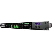
- Legal Notices
- Trademarks
- Footage
- Contents
- Chapter 4 Using Tools 107
- Chapter 5 Logging 118
- Chapter 6 Preparing for Capture 159
- Chapter 7 Capturing Media 223
- Chapter 8 Importing Files.... 281
- Chapter 9 Working with Bins.... 323
- Chapter 10 Acquisition of File-Based Media (AMA) 374
- Chapter 11 Managing Media Files 439
- Chapter 12 Viewing and Marking Footage 486
- Chapter 13 PhraseFind.... 555
- Chapter 14 Creating and Editing Sequences....575
- Chapter 15 Script-Based Editing 624
- Chapter 16 Using the Timeline 667
- Chapter 17 Working with Trim Edits.... 732
- Chapter 18 Working with Audio....759
- Chapter 19 Using External Audio Devices 858
- Chapter 20 Using Avid Artist Series Controllers....890
- Chapter 21 Using Audio Plug-Ins 918
- Chapter 22 Exporting Frames, Clips, or Sequences ..... 1005
- Chapter 23 Generating Output.... 1038
- Chapter 24 Conforming and Transferring Projects.... 1107
- Chapter 25 Working with Avid Interplay from an Avid Editing System ..... 1134
- Chapter 26 Interplay Synced Projects 1203
- Chapter 27 Using Your Avid Editing Application with Interplay Sphere ..... 1214
- Chapter 28 Using Interplay Transfer to Export Media.... 1231
- Chapter 29 Using MultiRez and Dynamic Relink 1245
- Chapter 30 MultiCamera Editing 1292
- Chapter 31 The Avid Marketplace 1308
- Chapter 32 Settings 1335
- Chapter 33 File Format Specifications 1451
- Chapter 34 Resolutions and Storage Requirements.... 1468
- Chapter 35 Working in HD and High-Resolution Projects 1498
- Chapter 36 Dual Link HD RGB Support 1536
- Chapter 37 International Character Support (ICS) in Avid Editing Applications 1538
- Chapter 38 Open I/O Support.... 1550
- Using This Guide
- Symbols and Conventions
- If You Need Help
- Avid Training Services
- Editing Overview
- Editing Workflow
- Starting a Project
- Preparing to Edit
- Editing a Sequence
- Outputting a Sequence
- Starting a Project
- Turning on Your Equipment
- Working with the Desktop
- Using the Windows Taskbar (Windows Only)
- To change the taskbar settings:
- Using the Macintosh Dock (Macintosh Only)
- To display the Dock:
- Using Shortcut Menus
- To use a shortcut menu:
- Using the Keyboard for Navigating in Dialog Boxes and Menus
- Option Command
- Using the Mouse Scroll Wheel for Navigating
- Customizing Mouse Functions
- To set the mouse scroll speed:
- To assign functions to additional mouse buttons:
- Optimum Performance (Windows 7)
- Optimum Performance (Macintosh)
- Antivirus Applications
- Starting Your Avid Editing Application (Windows)
- Starting Your Avid Editing Application (Macintosh)
- To start your Avid editing application, do one of the following:
- Working with Projects
- Private
- Shared
- External
- Synced
- Avid Projects and Avid Users Folders
- Locations of Avid Project Folders
- Locations of Avid Users Folders
- Files and Folders Created For Projects
- Files and Folders Created For User Profiles
- Select Project Dialog Box
- Element Description
- Element Description (Continued)
- Project Types
- Project Type Source Footage Transfer Color Space
- Creating a New Project
- To create a new project:
- Option SD HD
- Setting the Project Format to Accommodate Variable Resolutions
- Working with Color Spaces in HD Projects
- Understanding the YCbCr Color Space
- Understanding the RGB Color Space
- Choosing a Color Space for Your Project
- Mixing Media of Different Color Spaces
- Setting the Project Color Space
- Changing the Project Color Space for an HD Project
- To change the project color space:
- Setting Project-Naming Conventions
- To use Windows compatible file names
- To extend project and bin names to 31 characters (Macintosh only)
- Opening and Closing Projects
- To open an existing project:
- To browse for a project in a location other than the default Shared and Private folders:
- To open a project automatically:
- To turn off the automatic opening of projects so that you can select another project when you start your Avid editing application:
- To open the startup project:
- To close the current project, do one of the following:
- Deleting a Project
- To delete a project:
- Deleting a project also deletes any bins that are in that project.
- Quitting and Turning Off Equipment
- To quit your Avid editing application and leave it immediately:
- To quit your Avid editing application and view the Select Project dialog box:
- To view remaining storage on your media drives:
- Quit your Avid editing application before you turn off your equipment.
- To turn off your equipment:
- Never remove media drives from your Avid system when it is turned on. Shut down the computer, and then remove the drives.
- Changing Project and User Names
- When you change a user name or a project name, make sure you change the name of the folder and all the files in the folder that have the old name. Your Avid editing application does not automatically change the names of corresponding files in the folder.
- To change a project name or user name:
- Backing Up Your Project Information
- To save your work on a drive or on removable media:
- To restore a project or user information from a backup storage device:
- Avid Attic Folder
- Retrieving Files from the Avid Attic Folder (Windows)
- To retrieve a file from the Avid Attic folder:
- To copy backup files to a new bin:
- Retrieving Files from the Avid Attic Folder (Macintosh)
- Working with the Project Window
- Overview of the Project Window
- Controlling Project Window Display
- Using the Bins Tab
- Viewing a List of Bins
- Creating a New Bin
- To create a new bin from the Project window:
- To place a bin in a folder:
- Renaming a Bin
- To change the name of a bin:
- Opening and Closing Bins
- To open a bin directly:
- To open several bins at once from the Project window:
- To open a bin from another project:
- To close a bin, do one of the following:
- Displaying Folders of Bins in the Bins List
- To create a folder in a project:
- To show or hide the folder's contents in the Bins list in the Project window:
- To view a list of only the folder contents and not the folders:
- Creating a Folder
- Deleting a Bin or Folder
- To delete a bin or folder from the Project window, do the following:
- Viewing and Emptying the Trash
- To view items in the Trash:
- To empty the Trash in the Bins list:
- Saving Bins
- To adjust the frequency of automatic saves:
- Saving Bins Manually
- To save a specific bin:
- To save selected bins:
- To save all the bins:
- Using the Settings Tab
- To view the Settings list:
- To open a setting:
- To view Help for a setting:
- Using the Format Tab
- Using the Usage Tab
- To view and update statistics for an open project:
- To print the Statistics file:
- Statistics File Structure and Layout
- Variable Description
- Importing the Statistics File into a Spreadsheet
- To import a Statistics file into Microsoft Excel:
- Displaying Disk Space Statistics
- To display disk space statistics in the Usage window:
- To update the display:
- To prevent recalculation:
- Using the Info Tab
- To open the Info display:
- To display system memory information:
- Item Description
- To open the Hardware tool, do one of the following:
- Managing Bins and Memory
- To free up memory:
- Click OK.
- Understanding User Profiles
- Managing User Profiles
- To create a user profile:
- To import user settings from another user or user profile:
- To return to the original user profile:
- To export user settings to another user or user profile:
- To update user profiles:
- To delete a user profile from your desktop:
- Customizing the Avid User Interface
- Changing Interface Component Colors
- To set the brightness and color of interface components:
- Changing Font and Point Size
- To change the font in the Project, Bin, Composer monitor, Script, or Timeline window:
- Using Workspaces
- To select a workspace, do the following:
- To customize the workspace:
- To remove your customizations:
- To link a mode button in the Timeline palette to a workspace:
- To delete a custom workspace:
- Linking User Settings and Workspaces
- To link a workspace to another setting:
- To link a workspace to an unnamed setting:
- Assigning a Workspace or Bin Layout Button
- To assign a workspace button:
- To assign a bin layout button:
- Using Bin Layouts
- To open a bin layout, do the following:
- To save a custom bin layout:
- To link a bin layout to a workspace view:
- To modify a bin layout:
- To delete a bin layout:
- Click OK.
- Working with Bins and Projects in an Avid Shared Storage Environment
- Sharing Bins and Projects in Avid Shared Storage
- Sharing Only Bins
- Sharing Both Bins and Projects
- Opening a Shared Project
- To open an existing project on the shared volume:
- Working with Locks and Shared Bins
- To open a bin without controlling the lock:
- To permanently lock a bin:
- To unlock the bin:
- Considerations for Working with Shared Bins and Projects
- Suggestions for Improving Performance When Working with Shared Bins
- Limitations When Working with Shared Bins and Projects
- Restrictions and Limitations for Locked Bins
- Limitation When Using the Shared Bin Lock Icon
- Drive Filtering in Networked Workflows
- Using Tools
- Using the Tools Menu
- To open a tool:
- Using Tabs
- To move a tool into a window:
- To move a tool into separate window:
- To view tool tabs that do not display in the tab bar, do one of the following:
- To organize tools by changing the order of tabs:
- To close a tool tab:
- Using a Deck Controller
- To open a deck controller:
- Deck Controller Window Reference
- The Command Palette
- Understanding Button Mapping
- The Blank Button
- Modifier Keys
- Button Description
- Mapping User-Selectable Buttons
- To map buttons or keys on the keyboard by using the Command palette:
- Mapping Menu Commands
- To map menu commands:
- Activating Commands from the Command Palette
- To activate a command from the Command palette:
- Using the Avid Calculator
- To use the Avid Calculator:
- To convert your totals at any time to another format:
- Using The Console Window
- Do not use the programming features of the Console without guidance from Avid. Contact your Avid Reseller with specific questions. (In North America, you can contact Avid Customer Support.)
- To display current system information:
- To review errors logged to the Console window:
- To get information with the Console window:
- To make your mapped network drives available:
- Using the Hardware Tool
- External Controllers as Editing Control Surfaces
- Logging
- Using Avid Log Exchange to Prepare Log Files for Import
- Converting Log Files with Avid Log Exchange (Windows)
- To convert a log file to an ALE file:
- Option Description
- Using Drag-and-Drop Conversion for Log Files (Windows)
- To convert a log file by using drag-and-drop conversion:
- Converting Log Files with Avid Log Exchange (Macintosh)
- Using Drag-and-Drop Conversion for Log Files (Macintosh)
- Viewing ASC Color Decision List (CDL) Parameters in Avid Log Exchange
- To view the ASC\_SOP and ASC\_SAT parameters in your Avid editing application:
- To view the ASC\_SOP and ASC\_SAT parameters in the EDL application:
- Log Formats Compatible with Avid Log Exchange
- Avid Log Specifications
- Global Titles
- Column Titles
- Data Entries
- Sample Avid Log
- Creating an Avid Log
- To open WordPad:
- To open Text Edit:
- To create a text document in TextEdit:
- To create an Avid Log by using a word processor or text editor:
- Your Avid editing application only accepts text files (ASCII format).
- Double-Checking Log Files
- Transferring Bins from MediaLog
- To transfer bins from MediaLog:
- To associate the transferred bins with your project:
- Logging Directly into a Bin
- Logging Preroll
- Logging Timecode
- Naming Tapes
- Logging with Avid-Controlled Decks
- To log clips directly into a bin from an Avid-controlled deck:
- Pausing the Deck While Logging
- To pause the deck while logging:
- Using a Memory Mark When Logging
- Logging with Non-Avid-Controlled Decks
- To log clips directly into a bin from a non-Avid-controlled deck:
- 【
- Understanding the Pulldown Phase
- Setting the Pulldown Phase
- To set the pulldown phase:
- Film-Related Log Information
- Displaying Film Columns
- To display film columns in the bin:
- Entering Pulldown Information
- Determining the Pulldown Phase
- To determine the pulldown phase:
- Modifying the Pulldown Phase Before Capturing
- To modify the pulldown phase directly in the Pullin column:
- To modify the pulldown phase for multiple clips:
- To modify the pulldown phase for multiple clips that have the same pulldown-to-timecode relationship:
- Entering Frames-per-Second Rates for PAL Transfers
- Entering Key Numbers
- To add key numbers:
- Entering Additional Timecodes
- To enter additional timecodes:
- Entering Ink Numbers
- To enter ink numbers:
- Exporting Shot Log Files
- To export a shot log based on clip information in a bin:
- To export an entire bin:
- Preparing for Capture
- Logging and Shot Logs
- Importing Shot Log Files
- To import shot log files into a bin:
- Preparing the Hardware for Capture
- Item Description (Continued)
- Getting Information About Striped Drives
- To get information about striped drives:
- Selecting the Sync Source for Capture
- To select the sync source:
- To check the sync source, do one or both of the following:
- Establishing Sync for Audio-Only Input
- Analog Audio Input
- Digital Audio Input
- Selecting Settings for Capture
- Selecting Video Resolutions and Media Drives
- To select a video resolution and media drives:
- Click the Capture tab.
- Click the Video Resolution menu, and select a video resolution.
- Select a video drive and an audio drive. To select the same drive for both video and audio, click the Single/Dual Drives Mode button until only a single drive menu opens.
- Disabling Video Resolutions
- To disable resolutions:
- To enable the resolutions you disabled:
- Setting Drive Filtering
- To set drive filtering in the Media Creation dialog box:
- Do one of the following:
- (Option) Click the Drive Filtering & Indexing tab.
- Select one or more drives to filter out:
- Click OK to save your settings.
- Selecting Settings for Preroll Method and for Capturing Across Timecode Breaks
- To select settings for capturing across timecode breaks:
- Preroll
- Method Description
- Capturing to Multiple Media Files
- For media file management purposes, any clip whose media exceeds the 2-GB limit has more than one media file associated with it.
- To capture video or audio to multiple OMF media files:
- General Settings for Capture
- Setting Description
- Capture-Related Settings for Film and 24p Projects
- Configuring Decks
- Configuring a Deck or Multiple Decks
- To configure a deck or multiple decks:
- Deleting Deck Configuration Elements
- To delete deck configuration elements:
- Understanding Timecode
- Connecting a DV Device
- Setting Up the Capture Tool
- Opening the Capture Tool
- To open the Capture tool:
- Selecting a Deck in the Capture Tool
- Command Description
- Activating Playback from an Available Deck
- Selecting a Source Tape
- To select a source tape:
- Selecting Source Tracks and Audio Channels
- To select only those tracks you want to capture:
- To group tracks for multichannel capture:
- Setting the Video and Audio Input in the Capture Tool
- Detecting a Valid or Locked Sync Signal
- Setting the Pulldown Switch
- To set the pulldown switch:
- Film Project Pulldown and Transfer Settings
- Capturing Digital Audio in Film Projects
- Selecting a Resolution in the Capture Tool
- Selecting a Target Bin
- To select a target bin:
- Selecting the Target Drives
- To target a single drive:
- To target separate drives for audio and video:
- To create and target a drive group:
- Selecting a Custom Preroll
- Preparing to Capture Audio
- Audio Project Settings for Capture
- Selecting the Audio Sample Rate and Controlling Audio Sample Rate Conversion
- To select the audio sample rate:
- To set a preference for audio sample rate conversion during capture:
- Selecting the Audio File Format
- To select the audio file format:
- Selecting the Audio Input Source
- To select the audio input source:
- Configuring the Sound Card (Software-Only Systems)
- To customize the sound card configuration:
- To reconfigure the sound card to the original application settings:
- To override the mute feature for surround sound:
- Understanding the Audio Tool
- Component Description
- Opening the Audio Tool
- To open the Audio tool, do one of the following:
- Adjusting Audio Input Levels
- To check and adjust input levels using an audio input device:
- Creating Tone Media
- To create tone media:
- Click OK.
- Using the Passthrough Mix Tool
- To open the Passthrough Mix tool, do one of the following:
- To choose the number of tracks (4 or 8) to display in the Passthrough Mix tool:
- To adjust audio in the Passthrough Mix tool:
- To change an audio level value in the audio panel in the Passthrough Mix tool, do one of the following:
- To adjust the pan values in the audio panel of the Passthrough Mix tool:
- Calibrating Audio Hardware for Avid Nitris DX and Avid Mojo DX
- To calibrate the audio channels for Avid Nitris DX or Avid Mojo DX using the Audio Hardware Calibration tool:
- To calibrate the audio input channels:
- To calibrate the audio output channels for Avid Nitris DX and Avid Mojo DX:
- Using the Console Window to Check Audio Levels
- To check peak levels in the Console:
- RP
- Preparing to Capture Video
- Opening the Video Input Tool
- Using the Factory Preset Buttons in the Video Input Tool
- Calibrating Video Input
- To calibrate the video input:
- Luminance Settings for Video Input
- Limitations When Using Consumer Decks or Decks Without Time-Base Correctors
- Capturing from Unstable Time-Base Sources
- Green Line in VHS Video
- Saving Video Input Settings
- If you do not use a name that matches the tape name, your system does not recall the setting automatically the next time you load the tape.
- To save the calibration settings for a tape:
- To create a customized default Video Input Tool setting:
- Adjusting Video Levels for Tapes Without Color Bars
- Capture Preparations Check List
- Capturing Media
- Capturing and Logging at the Same Time
- Naming Clips and Adding Comments in the Capture Tool
- To name a clip and add a comment before capturing:
- To add clip names and comments during capture:
- Capturing by Setting Both Marks
- To capture by specifying a mark IN and a mark OUT:
- Capturing by Setting Only One Mark
- To set only one mark and enter the other mark on-the-fly:
- Capturing On-the-Fly
- To capture on-the-fly:
- Preparing to Autocapture
- Autocapturing
- To autocapture:
- Capturing from a Non-Avid-Controlled Deck
- To capture with manual deck control:
- Capturing with Time-of-Day Timecode
- To capture with time-of-day timecode:
- Capturing Directly from a DV Device
- Capturing DV 25 Media
- Capturing DV 50, DVCPRO HD, or HDV Media
- Selecting a DV Device
- Understanding DV Capture Offset
- RS-422 Controlling a DV Device Configuration
- FireWire Configuration Without Timecode
- FireWire Configuration with Encoded Timecode
- Example of a Capture with Offset
- Capturing DV Material with Offset
- To offset the sequence for capture:
- Frame Chase Capture
- Understanding Frame Chase Capture
- Conventional Capture
- Enabling Frame Chase Capture
- To enable and set options for Frame Chase capture:
- Requirements and Guidelines for Frame Chase Capture
- Batch Capturing from Logged Clips
- Preparing to Batch Capture
- To prepare for unattended batch capturing:
- Batch Capturing Clips
- To batch capture clips:
- Recapturing and Decomposing
- Understanding Recapturing
- Recapturing Master Clips and Subclips
- Recapturing Sequences
- Understanding Decompose and Expert Decompose
- Expert Decompose
- Target Formats for Expert Decompose
- Decomposing Sequences
- To decompose one or more sequences:
- If you attempt to trim or add effects with no handles, you receive an error message notifying you that there is insufficient media.
- Click OK.
- Using Expert Decompose
- To sort or reverse sort a column of information:
- To select or deselect a single tape/source or clip to decompose:
- To select or deselect multiple tapes/sources or clips to decompose:
- To deselect all selected tapes/sources or clips:
- To select the target format for a tape/source or clip:
- Recapturing a Sequence Without Using Decompose
- To recapture a sequence:
- If you attempt to trim or add effects with no handles, you will receive an error message notifying you that there is insufficient media.
- Alternate Source Capture
- To batch capture with an alternate source:
- Using Capture Function Keys
- Press To
- To change function key commands for capturing media:
- Handling Errors During the Capture Process
- To enable or disable logging to the Console window during capture:
- To open the Console window:
- To respond when your Avid editing application pauses during capture and is not logging to the Console:
- Creating Subclips While Capturing
- To create a subclip on-the-fly:
- To set the duration of a timed subclip:
- To create a timed subclip:
- Adding Markers On-the-Fly While Capturing
- To add a marker to a frame while capturing:
- Naming a New Tape from the Keyboard While Capturing
- To create a new tape name by using a keystroke in Capture mode:
- Controlling Decks from the Keyboard
- Ejecting Tapes with a Button or Key
- To eject tapes by using a button:
- Using Dolby E Media
- Selecting Dolby E Safe Settings
- To select Dolby E safe settings:
- Capturing Media with Dolby E Information
- Capture tool with blue Dolby E Safe button
- To capture media while protecting Dolby E information:
- Delaying Audio During Capture
- To offset your audio:
- Live Capturing with External Timecode
- To capture with external timecode:
- Capturing to the Timeline
- To capture to the Timeline:
- Capturing Video Without Pulldown into a 24p NTSC Project
- Remote Play, Capture, and Punch-In
- Function Description
- Selecting Remote Play and Capture Settings
- To open the Remote Play and Capture Settings dialog box:
- Enabling Remote Capture
- To enable Remote Capture:
- Enabling Remote Play
- To enable Remote Play:
- Setting up Your System for Remote Punch-In
- To record audio using Remote Punch-In:
- Relinking Clips by Key Number
- To relink clips by key number:
- To relink a sequence to the original clips:
- Modifying the Pulldown Phase After Capturing
- To check for an incorrect pullin frame:
- To determine the correct pullin frame, use one of the following approaches:
- To modify the clip information after you determine the pullin frame:
- DV and HDV Scene Extraction
- To set up DV and HDV scene extraction before capturing:
- To set up DV scene extraction after capturing:
- Using the Panasonic VariCam
- To use the VariCam camera with your Avid editing application:
- Importing Files
- Preparing to Import Files
- Creating and Modifying Import Settings
- To create a new Import setting:
- To modify an existing Import setting:
- Importing Media Files
- To import files:
- Do one of the following:
- Option Description (Continued)
- Importing with Multichannel Audio
- To specify the multichannel audio mix for imported clips:
- Button Track Format
- Importing Audio Files from a Music CD
- To import audio files from a music CD:
- Adjusting Gain Before Importing Audio Files
- To adjust the gain before import:
- To adjust the gain after import:
- Sample Rate Conversion and Audio Import
- Setting Sample Rate Conversion Options Before Importing Audio Files
- To set sample rate conversion options:
- Click OK.
- Photoshop Graphics Import
- Single-Layer Photoshop Graphics
- Multilayer Photoshop Graphics
- Example of Multilayered Photoshop Graphics Import
- Support for Multilayered Photoshop Graphics Import
- Importing Photoshop Files
- To import a multilayered Photoshop file:
- To preserve layer effects:
- Digital Bars and Tone
- Importing Color Bars and Other Test Patterns
- To import a test pattern from a file:
- Importing Editcam Files
- To import Editcam files:
- Setting XDCAM Import Options
- Importing XDCAM Media
- Importing XDCAM EX Media
- To import an XDCAM EX clip using Avid AAF:
- To import an XDCAM EX clip using MXF for NLEs:
- Automatically Importing Proxy Media from an XDCAM Device
- To import proxy media from an XDCAM device:
- Importing Proxy Media from an XDCAM Disk
- To import proxy media from a disk:
- Copying XDCAM Proxy Media to a Local Drive or a Server
- Manually Importing XDCAM Media from the XDCAM Disk
- Importing Essence Marks as Markers in XDCAM Media
- To import Essence Marks as markers:
- Editing XDCAM Proxy Media
- To set the playback options for XDCAM media:
- Batch Importing High-Resolution XDCAM Media from the XDCAM Disk
- To batch import high-resolution XDCAM media:
- Editing and Finishing High-Resolution XDCAM Media
- Importing P2 Clips and Media
- To import P2 clips directly from a P2 card or a copy of a P2 card on a drive:
- To import media from a P2 card:
- Importing Sequences from Pro Tools through Interplay
- To import a sequence from Pro Tools:
- Using the Drag-and-Drop Method to Import Files
- To import one or more files by using the drag-and-drop method:
- Reimporting Files
- Reimporting requires your original source file. Do not delete the media files for imported files unless you have access to the source files.
- To reimport files:
- Batch Import Dialog Box
- Area Control Description
- Working with Bins
- Object Icons in Bins
- Bin Views
- Using Text View
- To enter Text view:
- To select column headings:
- Sorting in Bins
- Sorting Clips and Sequences
- To sort clips in ascending or descending order:
- To reapply the last sort, do one of the following:
- To perform a multilevel sort using the information in the bins:
- To sort clips by color:
- Understanding Bin Views
- View Description
- Saving a Custom Bin View
- To save a bin view:
- To change a custom bin view with the Bin View dialog box:
- Using Frame View
- To enter Frame view:
- To enlarge the frame size:
- To reduce the frame size:
- To rearrange a single frame:
- To rearrange multiple frames:
- To align all frames to an invisible grid:
- To align selected frames to an invisible grid:
- To space the frames evenly to fill the Bin window:
- To arrange frames in the order in which they are sorted in Text view:
- To change the frame identifying the clip:
- Using Script View
- To enter Script view:
- To type text in the script box:
- To change the represented frame in Script view:
- To rearrange clips in Script view:
- Bin Procedures
- Using Bin Tabs
- To move a bin into another bin:
- To move a bin into separate window:
- Using the Bin Fast Menu
- Selecting Clips and Sequences
- Duplicating, Copying, and Moving Clips and Sequences
- To duplicate clips or sequences:
- To move clips or sequences from one bin into another:
- To copy clips or sequences from one bin to another bin:
- Copying Clips and Sequences
- Deleting Items from a Bin
- (Macintosh) To delete clips, subclips, and sequences with their media files from a bin:
- Changing the Bin Background Color
- To change the bin background color:
- Assigning Colors to Objects in a Bin
- To add a Color column to a bin:
- To assign a color to a clip, subclip, sequence, or effect clip in a bin:
- To reset clip color to the default, do one of the following:
- Locking and Unlocking Items in a Bin
- To lock items:
- To unlock previously locked items:
- Selecting Offline Items in a Bin
- Selecting Media Relatives for an Object in a Bin
- To identify media relatives:
- Selecting Sources Used by an Object in a Bin
- To identify sources for a clip or sequence:
- Selecting Unreferenced Items in a Bin
- To identify unreferenced clips:
- Working with Bin Columns
- Moving, Aligning, and Deleting Bin Columns
- To move a text column in a bin:
- To align bin columns:
- To hide or delete a column:
- Duplicating Bin Columns with Timecode Information
- To duplicate a timecode column:
- Adding Customized Columns to a Bin
- To add a new custom column:
- Changing a Custom Bin Column Heading
- To change the name of a custom column:
- Adding a Metadata Bin Column Heading
- To add a metadata column:
- Moving Within Column Cells
- Shortcut Description
- Copying Information Between Columns
- To copy column information to another column:
- Displaying Timecodes in a 24p or 25p Project
- Adding Timecode Columns to a Bin or the Media Tool
- To add timecode columns to a bin or to the Media tool:
- Frame Counting for Timecodes
- Adding Timecode Values to the Timecode Columns
- To add timecode values to the timecode columns:
- Modifying Clip Information
- Bin Column Headings
- Bin Column Heading
- Description
- Bin Column
- Heading Description
- Bin Column Heading Description
- Modifying Data in Bins
- When you modify tape names and timecodes it affects any key numbers entered for the selected clips.
- To modify the clip data directly in a bin:
- To modify selected data using the Modify command:
- Modify Command Options
- Copying Information from Another Cell in a Custom Bin Column
- To copy information from another cell in a custom column:
- Working with Film Information in Bins
- Film Scene Workflow
- Tracking Frames Based on File Name
- To display the frame count numbers in a bin and cut list:
- To display the frame count numbers above the Source or Record monitors in your Avid editing application:
- Selecting a Film Gauge
- To specify the gauge of the film:
- Tracking 3-Perf Counts
- To specify the perf value:
- Selecting an Edgecode Type
- To select an edgecode type:
- Edgecode Type Edgecode Format Sample Edgecode
- Creating a Storyboard
- To create a storyboard:
- Setting the Bin Display
- To set the bin display:
- Sifting Clips and Sequences
- To sift clips or sequences:
- To view the entire bin:
- To view the sifted bin:
- Understanding Sifting Timecodes or Keycode Ranges
- Sifting Timecodes or Keycode Ranges
- To sift for a timecode or keycode number within a specific range:
- Working with Restricted Material
- To ignore the warning for the rest of the editing session and continue with editing or output:
- To view Restriction comments, do one of the following:
- To see changes in Restriction comments while you are editing:
- Printing Bins
- To print entire bins:
- To print a single frame of a clip or sequence:
- Acquisition of File-Based Media (AMA)
- The Avid Media Access (AMA) Workflow
- Considerations and Limitations for AMA
- Viewing Installed AMA Plug-ins
- To display the list of installed AMA plugins:
- Selecting the AMA Settings
- To set up AMA:
- Copying File-Based Media to a FireWire or Network Drive
- To copy the card or disk media to another drive:
- Dragging and Dropping File-based Media Directly to a Bin
- To drag and drop files directly into a bin:
- Creating Dynamic Media Folders
- To create a Dynamic Media Folder:
- Setting Option Description
- Action Option Description
- Linking Media with AMA
- To automatically link clips from a third-party device:
- To link clips from a virtual volume with AMA:
- To link clips from a file with AMA:
- Click Open.
- Relinking to AMA-Linked QuickTime Files
- To relink to AMA file(s):
- Spanned Clips
- AMA Linking with Ancillary Data
- AMA Linking with Multichannel Audio
- To specify the multichannel audio mix for linked AMA clips:
- To save a custom map of linked audio channels as a settings template:
- The AMA Plug-in Log File
- Using Virtual Volumes
- To unmount a virtual volume:
- Virtual Volumes and AMA Bins
- To create a new bin on the same virtual volume:
- Deleting Clips
- To delete files from cards/volumes:
- To delete files on a local drive in your Avid editing application:
- Using AMA Plug-Ins
- Using XDCAM and XDCAM EX and XDCAM SR AMA Plug-Ins
- A typical workflow is as follows:
- Using XDCAM Multiple Resolution Clips with AMA
- Switching Between Multiple Resolution Media
- To switch from low-resolution to high-resolution media:
- Consolidating Multiple Resolution Media
- To consolidate high-resolution media:
- Using the P2 AMA Plug-In
- Using the AVCHD AMA Plug-In
- Using the Canon XF AMA Plug-In
- Using the GFCAM AMA Plug-In
- Working with Shot Marks and Check Marks with GFCAM Media
- Using the RED AMA Plug-In
- Preparing your RED Clip for Transcode, Mixdown, or Render
- To prepare your RED clip for transcoding, mixdown or rendering:
- Adjusting RED Source Settings
- To change the RED source settings:
- Click Apply.
- Click OK to save your change and close the window.
- Using RED Source Settings
- Applying a RED Source Setting
- To apply a source setting to a RED clip:
- Setting Origin
- Click Apply.
- Click OK to save your settings and close the window.
- To import additional source settings:
- Using the QuickTime AMA Plug-In
- A QuickTime AMA workflow is as follows:
- Adjusting QuickTime Source Settings
- To change the QuickTime source settings:
- Applying a QuickTime Source Setting
- To apply a source setting to a QuickTime clip:
- Understanding the QuickTime Source Settings Histogram
- Using the MXF AMA Plug-In
- Workflow for Editing Clips with Ancillary Data and AMA
- Understanding the Source Settings Histogram
- Adjusting the Source Settings Histogram
- To adjust the Source Settings Histogram:
- Option Result
- Working with Export Volumes
- Creating an Export Volume
- To create a new export volume:
- Moving Assets to an Export Volume
- To move assets to the Export Volume:
- Committing Assets to an Export Volume
- To commit the assets to the Export Volume:
- Archiving the AS-02 Bundle
- To archive the Assets Folder.
- Linking to an existing AS-02 Bundle
- To link to an existing AS-02 Volume:
- AS-11 Support
- To export a sequence as AS-11:
- Managing Media Files
- Working with Media Files in an Avid Interplay Environment
- Configuring Avid Editing Systems for the Interplay Engine and Interplay Transfer
- Using Avid Editing Systems in an Avid Workgroup Environment
- Using Avid Editing Systems in an Avid LANshare Workgroup
- To enable the client to recognize LANshare workspaces:
- Viewing Media with a 100Base-T Connection to Avid ISIS
- Understanding Drive Mounting
- Mounting and Unmounting Drives
- To mount all drives:
- Using the Media Tool
- Basic Media Tool Features
- Using the Media Tool in an Avid Interplay Environment
- Opening the Media Tool
- To open the Media tool:
- Deleting Media Files with the Media Tool
- To delete selected media files:
- Consolidating Media
- Master Clips
- Subclips
- Sequences
- Using the Consolidate Command
- To consolidate master clips, subclips, or sequences:
- Using the Transcode Command
- To use the Transcode option:
- Consolidate or Transcode AMA Clips Only
- Background Consolidate and Transcode
- The Background Queue Window
- Using Background Consolidate and Transcode
- To manage background transcode with the Background Queue window:
- Loading the Media Database
- To update the offline sequences with the new media files:
- Refreshing Media Directories
- To refresh media directories:
- Deleting Unreferenced Clips and Media
- To quickly view remaining storage on your media drives at any time:
- To delete all unreferenced clips and media files:
- Backing Up Media Files
- Finding a Related Media File
- To find a related media file:
- Relinking Media Files
- To relink master clips, subclips, or sequences:
- Select options.
- Relink selected items to:
- Relink by:
- Video Relink Parameters
- Relinking by Resolution
- To relink a clip by resolution:
- Relinking to Selected Clips
- To relink to selected master clips and subclips:
- Relinking Tape and File Based Media
- To relink tape and file based media:
- Relinking Consolidated Clips
- To relink consolidated subclips or sequences:
- Relinking Moved Projects
- Unlinking Media Files
- To unlink master clips from their current links:
- Archiving and Restoring Media Files to Videotape
- Archiving Media Files
- To archive a video project's media files:
- Select the appropriate options.
- For Subclips and Sequences:
- For Sequences:
- Click OK.
- Restoring an Archive from Videotape
- To restore an archive from videotape:
- Sequence and Clip Information Summary
- Example 1: Preparing for Online Editing
- Example 2: Finding Specific Effects
- Example 3: Plug-in Information
- Creating a Summary of Effects and Source Information
- To generate a summary report:
- Summary Information Options
- Viewing and Marking Footage
- Viewing Methods
- Viewing Method Description
- Customizing the Composer Window and Monitors
- Resizing the Composer Window and Monitors
- To resize the Source and Record monitors:
- To resize a pop-up monitor:
- To switch back to the standard-size Source/Record monitors:
- To hide the Source monitor and enlarge the Record monitor:
- To reduce the Record monitor to its standard size:
- To toggle between the single Record monitor and the Source/Record monitors:
- To hide or display the video in a monitor:
- To hide the controls in a monitor:
- Displaying Tracking Information
- To display tracking information:
- Tracking Format Options
- Panes in the Tracking Information Menu
- Pane Description
- Pane Description (Continued)
- Using the Info Window
- To display information from the Record monitor:
- To display information from a bin:
- Using the Timecode Window
- To set a timecode display:
- Playing Video to the Client Monitor
- Activating and Deactivating the Client Monitor Display
- Selecting the Video Display Settings
- To select Video Display settings:
- Playing Video to a Full-Screen Monitor
- To enable full screen playback:
- To disable full screen playback:
- Adjusting the Play Delay Offset
- To adjust the offset:
- Using the Tool Palette
- To use the Tool palette:
- To leave the Tool palette open and move it to another location:
- To view the names of the buttons in the Tool palette:
- To display labels on the Tool palette buttons:
- Playing Selected Clips in a Loop
- To play several clips in a continuous loop:
- Loading and Clearing Footage
- Loading Clips or Sequences into Monitors
- To load clips or sequences into a monitor:
- Switching Between Loaded Clips
- To switch between clips:
- Clearing Clips from Monitors
- To clear the monitor or the clip or sequence names from the menu:
- Controlling Playback
- Using Position Bars and Position Indicators
- To access frames in or move through loaded footage, do one of the following:
- To display markers when scrubbing:
- Playback Control Buttons
- Button Primary Default Location Function
- To play in standby mode:
- Stepping Forward and Backward by Field
- To use single-field step:
- Playback Control Using the Keyboard
- Keys Function
- Playing Footage with the J-K-L Keys (Three-Button Play)
- To shuttle through the footage using the J-K-L keys on the keyboard:
- Press the L Key To Play Footage at NTSC Rate PAL Rate 24p Rate
- To slow or change play direction one speed at a time:
- To pause shuttling:
- To stop shuttling:
- Using the Mouse for Playback
- To jog or shuttle by using the mouse:
- To pause shuttling with the mouse:
- To quit jogging or shuttling with the mouse:
- Playing Back to a DV Device
- To play back to a DV device connected through a 1394 port:
- Format Availability
- Video Quality Options for Playback
- Setting the Video Quality for Playback
- To set the video quality for playback:
- Marking and Subcataloging Footage
- Marking IN and OUT Points
- To mark IN and OUT points:
- ]
- To clear the IN point, do one of the following:
- 1
- To clear the OUT point, do one of the following:
- C
- To clear both the IN and OUT points:
- To set a new IN point:
- To set a new OUT point:
- To move a mark icon:
- Marking an Entire Clip or Segment
- To mark an entire clip or segment:
- Creating Subclips
- To create subclips:
- Creating Subsequences
- To create a subsequence:
- Subclips and Audio Sync for 24p and 25p Projects
- Marking Audio Clips
- To mark IN and OUT points on audio tracks:
- To remove audio IN and OUT points:
- Using Markers
- Suggested Uses for Markers
- Adding Markers While Editing
- To add markers and comments while in an editing session:
- Adding Spanned Markers While Editing
- To add spanned markers and comments while in an editing session:
- Adding Markers On-the-Fly while Playing
- To add markers on-the-fly while playing:
- To add comments to the markers:
- To keep the Marker edit pane from opening:
- Finding Markers
- Editing Marker Information
- To edit Marker information in the Marker edit entry window:
- Copying Markers from Source Clips
- To automatically copy source markers as you edit:
- Marking an Area Using Markers
- To mark the area between two markers:
- Moving to the Previous or Next Marker
- To move to the previous marker:
- To move to the next marker:
- Deleting Markers
- To delete a single marker:
- To delete markers using the Markers window.
- Using the Markers Window
- Viewing Markers in the Markers Window
- To view markers in the Markers window:
- Working in the Markers Window
- You can also:
- To select a marker item:
- To browse through the list of marker items:
- To go to the frame marked by a marker item:
- To display the frame associated with a marker:
- To display a timecode column, a footage column, or a frame number column in the Markers window:
- To sort markers:
- To change column widths:
- To change the color of a Marker icon:
- To delete markers:
- Exporting and Importing Markers
- To export markers:
- To import markers.
- Creating a Marker Text (.txt) File
- To add comments or information into the Marker text file:
- Copying and Pasting Markers Using the Markers Window
- To copy markers from a clip and paste them into a new clip using the Markers window:
- To copy markers from a clip and paste them into a sequence using the Markers window:
- To copy and paste markers using the Markers window and a text editor:
- Printing the Contents of the Markers Window
- To print the current view of the Markers window:
- To print the complete contents of the Markers window:
- Disabling the Marker Edit Window
- Finding Frames, Clips, and Bins
- Using Timecode to Find a Frame
- To cue to a frame based on a known timecode:
- Format Description
- To cue a frame using frame offset timecode:
- Searching for a Clip or Sequence with Text Find
- Things You Should Know About Text Find
- To open a search window:
- Setting the Location of the SearchData folder
- To choose the location of the SearchData folder:
- Using Match Frame
- To use Match Frame to locate the source clip for a selected frame or motion effect:
- Performing a Reverse Match Frame
- To perform a reverse match frame:
- Selecting Tracks for Matching Frames
- To matchframe a selected frame on a single track:
- Finding a Bin
- To find the bin in which a specific clip is located:
- To find the bin in which a specific sequence is located:
- To find the bin in which a specific clip in a sequence is located:
- Locating a Master Clip from a Subclip in a Sequence
- To locate a master clip from a subclip:
- Finding a Frame
- To find a frame:
- Insert the tape.
- PhraseFind
- Purchasing and Activating PhraseFind
- How Do I Purchase PhraseFind?
- How Do I Activate PhraseFind?
- What Will I Need to Activate PhraseFind?
- To retrieve your System ID with a dongle attached:
- Running the 30-Day Trial of PhraseFind
- To run PhraseFind for a 30-day trial period:
- To purchase PhraseFind during your 30-day trial period:
- If You Purchased PhraseFind Through the Find Window
- To purchase PhraseFind through the Avid editing application's Find Window:
- If You Purchased PhraseFind through an Avid Reseller or Directly Online
- To open the Avid License Control tool:
- Activating PhraseFind with the Avid License Control Tool
- To copy system information from the License Profile tab:
- To activate PhraseFind with the Avid License Control tool and with an Internet connection:
- To activate PhraseFind with the Avid License Control tool and with no Internet connection:
- Activating Additional Regional Language Packs
- Activating Additional Language Packs
- Deactivating the PhraseFind License
- Deactivating PhraseFind
- Understanding PhraseFind
- Things You Should Know About PhraseFind
- Selecting a Language
- To select a language:
- Using PhraseFind
- To open the Find window:
- The Results Window
- To resize the Results window:
- To display columns:
- To move columns:
- To sort a column:
- To load a clip in the Source monitor:
- Filtering Your Find Results
- To filter a search:
- Find Window Attributes
- Results Window Attributes Description
- Creating and Editing Sequences
- Entering Source/Record Mode
- To enter Source/Record mode from another mode:
- Creating a New Sequence
- To create a sequence with the New Sequence command:
- Changing the Name and Timecode for a Sequence
- To rename a new sequence and set a start timecode:
- To change the start timecode of a sequence in a bin:
- Track Display for New Sequences
- User Preferences for Creating Tracks
- Adding Filler
- To add filler at the start of a sequence, do one of the following:
- To add filler anywhere in a sequence:
- Making a First Edit
- To begin editing:
- Creating an Instant Rough Cut
- To create a rough cut from a bin:
- Undoing or Redoing Edits
- Editing Additional Clips into the Sequence
- Performing an Insert or Splice-in Edit
- To perform an insert edit:
- Performing an Overwrite Edit
- To perform an overwrite edit:
- Performing a Replace Edit
- To perform a replace edit:
- Enabling Single-Mark Editing
- To enable single-mark editing:
- Mixing Frame Rates and Field Motion Types
- How Your Avid Editing Application Handles Mixed Rate Clips
- Motion Adapter Effects
- User Interface Summary for Mixed Rate Clips
- Illustration Description
- Viewing Mixed Rate Clips in the Timeline
- Viewing and Adjusting Motion Adapter Parameters
- To view parameter values for a motion adapter and adjust the render type:
- To promote a motion adapter to a Timewarp effect
- Modifying the Field Motion Attribute for a Clip
- To modify the Field Motion attribute for a clip or subclip:
- Considerations When Working with Mixed Rate Clips
- Playback of Mixed Rate Material with Different Frame Sizes
- Playback of Mixed Rate Material Using XDCAM AMA Media
- Behavior of Mixed Rate Material at Different Video Quality Settings
- Transcoding Mixed Rate Material
- Grouped Clips and Mixed Rate Material
- Working with Markers on Mixed Rate Material
- Effect Templates and Mixed Rate Material
- Dynamic Relink and Mixed Rate Material
- Mixing Frame Sizes and Aspect Ratios
- How Your Avid Editing Application Reformats Clips in Sequences
- Changing the Aspect Ratio for a Project
- To change the aspect ratio for a project, do one of the following:
- To recreate titles at the new aspect ratio:
- Modifying the Reformat Attribute for a Clip
- To set the Reformat value for an individual clip or subclip:
- Reformatting Options Reference
- Refreshing Sequences to Use Current Clip Attributes
- To refresh a sequence, do one of the following:
- To refresh multiple sequences:
- Lifting, Extracting, and Copying Material
- To lift material:
- To extract material:
- To copy material to the Clipboard:
- Using the Avid Clipboard
- To place a marked section of the sequence into the Clipboard at any time:
- To keep the Clipboard contents throughout a session, do one of the following:
- To restore material from the Clipboard:
- Adding Comments to Sequence Clips
- To add comments to the clips in a sequence:
- To display comments in the Timeline:
- Playing Back a Sequence
- To play a sequence:
- To start a playback loop:
- Playback Performance Tips
- Playing a Limited Duration of a Sequence
- To play a limited duration of a sequence:
- Understanding Sync Breaks
- Tips for Avoiding Sync Breaks
- Fixing Sync Breaks
- To restore frames to sync while Trimming:
- To fix sync in Source/Record mode:
- To fix sync when Segment editing:
- To customize the Sync Breaks display:
- Understanding Sync Lock
- Syncing with Tail Leader
- To eliminate a sync break when the leaders do not line up:
- Syncing with Markers
- To mark sync points with markers:
- To add a note whenever you park on the marker frame (such as Music sync or Sound Effect sync):
- To determine if sync is broken after an edit:
- To adjust the sync break:
- To restore sync:
- Using Add Edit When Trimming
- To use the Add Edit button while trimming:
- Ganging Footage in Monitors
- To gang footage in monitors:
- Sync Point Editing
- To perform a sync point edit:
- Autosyncing Clips
- Understanding Autosyncing
- Creating an Autosynced Subclip
- To create an autosynced subclip:
- Understanding AutoSequence
- Adding Audio or Video to Original Videotape Using AutoSequence
- To add audio or video to your original videotape:
- Resyncing Subframe Audio
- Resyncing Audio for a Selected Subclip
- To resync audio for a selected subclip:
- Working with Phantom Marks
- To enable phantom marks:
- Setting One Mark
- Adding a Second Mark
- Creating Video and Audio Leaders
- To create leaders for picture tracks:
- To create tail leader for audio tracks:
- Script-Based Editing
- Understanding Lined Scripts
- Script Integration — Lining in the Digital Realm
- Script Integration Workflow
- Using Script Integration in Video Projects
- Understanding the Script Window
- Script Settings
- Script Window Behavior
- Working with the Script Window
- To set Script settings:
- To import a new script:
- To select text encoding:
- To open, close, or save the Script window:
- To explore the Script window:
- To adjust the left margin of an imported script:
- To open the Info window from a Script window:
- Working with Script Text
- To change the font and font size of imported script:
- To select a single line of script:
- To select several lines of script, use one of the following methods:
- To extend an existing selection:
- To cut or copy lines of script and then paste them:
- To remove lines of script:
- Working with Page or Scene Numbers and Searching in a Script
- To add a page or scene number:
- To change a page or scene number:
- To delete a page or scene number:
- To search for a page or scene number:
- To search for text in a script:
- Linking Clips to a Script
- To link clips to the script:
- 5/2.sync.01 05
- 5/1.sync.01 05
- 5/7 05
- 5/6 05
- 5/5 05
- 5/4 05
- 5/3 05
- 5/2 05
- 5/1 05
- Interpolating Position for Script Integration
- Working with Slates in the Script Window
- To select slates, do one of the following:
- To enlarge or reduce the slates:
- To hold slates on screen, do one of the following:
- To hide or show the slate frames, do one of the following:
- To control the number of takes that display for a nonactive slate, do one of the following:
- To move a slate, do one of the following:
- To delete a slate:
- Working with Takes in the Script Window
- To select takes, do one of the following:
- To add another take to an existing slate:
- To delete one or more takes:
- You cannot undo the deletion of takes. To restore a take after deletion, add the take again using the procedure above.
- To display the take numbers in the tab of each take:
- To change the representative frame that appears in the slate for a take:
- To load individual takes into the Source monitor:
- To load multiple takes into the Source monitor:
- To play back a take, do one of the following:
- To change the length of a take line:
- Indicating Off-Screen Dialog in a Script
- To indicate off-screen dialog:
- To remove one or more off-screen indicators:
- Using Color Indicators in the Script Window
- To apply color to takes:
- To remove one or more color indicators:
- Script Marks
- Placing Script Marks Manually
- 亚
- To place script marks manually:
- Using Real-Time Screening and Marking
- To use real-time screening and marking:
- To stop the playback loop:
- Marking with ScriptSync
- To add script marks with ScriptSync:
- Click OK.
- (Option) Press Ctrl+. (period) to cancel the process after it has started.
- Purchasing and Activating ScriptSync
- How Do I Purchase ScriptSync?
- How Do I Activate ScriptSync?
- What Will I Need to Activate ScriptSync?
- Running the 30-Day Trial of ScriptSync
- To run ScriptSync for a 30-day trial period:
- To purchase ScriptSync during your 30-day trial period:
- If You Purchased ScriptSync Through Script > ScriptSync Menu Selection
- To purchase ScriptSync through the Avid editing application's Script > ScriptSync menu:
- If You Purchased ScriptSync through an Avid Reseller or Directly Online
- Activating ScriptSync with the Avid License Control Tool
- Click Copy.
- To activate ScriptSync with the Avid License Control tool and with an Internet connection:
- To activate ScriptSync with the Avid License Control tool and with no Internet connection:
- Deactivating the ScriptSync License
- Deactivating ScriptSync
- Loading and Playing Marked Segments
- To load the marked segment of a take:
- To load all the coverage for a range of lines:
- Moving or Deleting a Script Mark
- To move a script mark:
- To delete a script mark:
- Finding Clips and Script
- To find the script linked to a loaded clip:
- To find source clips and bins:
- Editing From the Script Window
- Revising the Script
- Interactive Screenings
- Assembling a Rough Cut From the Script Window
- To quickly assemble a rough cut from the Script window:
- Splicing a Script Range
- To splice a range:
- Using the Timeline
- Customizing Timeline Views
- Examples of Customized Timeline Views
- Purpose Description
- Purpose Description (Continued)
- Using the Timeline Fast Menu
- To use the Timeline Fast menu:
- Timeline Fast Menu Options
- Enlarging and Reducing Timeline Tracks
- To enlarge or reduce the height of tracks:
- Moving Timeline Tracks
- To move a track:
- Displaying Clip Colors in the Timeline
- To display clip colors in the Timeline:
- Select one or more of the following:
- To change the display colors for the Resolution Tracking, Offline, Mixed Rates, or SD/HD options:
- To reset the display colors for the Resolution Tracking, Offline, Mixed Rates, and SD/HD options:
- Changing the Track Color
- To change the color of the selected tracks in the Timeline:
- Assigning Local Colors to Clips in the Timeline
- To assign a local clip color:
- To remove a local clip color:
- Displaying Timecode Tracks in the Timeline
- To customize the tracks to be displayed in the Timeline:
- Showing Markers in the Timeline
- To change the display of markers in the Timeline:
- Setting the Playback Option for the Timeline
- To set the playback option:
- Disabling the Smart Tool in the Timeline
- To disable the Smart tool using the Timecode ruler or the Timecode track:
- Using the Full-Screen Timeline
- To resize the Timeline window:
- To restore a resized Timeline window to its default position:
- To enlarge tracks:
- To reduce tracks:
- The Timeline Palette
- Icon Tool Description
- The Track Control Panel
- Using the Track Control Panel
- To show the Track Control panel, do one of the following:
- Displaying Source Material in the Timeline
- Displaying the Timeline Top Toolbar
- To show the Timeline top toolbar:
- To hide the Timeline top toolbar:
- Managing Customized Timeline Views
- To name a Timeline view or to change a view's name:
- To restore the default view in the Timeline:
- Using Timeline View Buttons
- To map a Timeline view button:
- To use a Timeline View button or key, do one of the following:
- Navigating in the Timeline
- Understanding the Timeline Position Indicator and Scroll Bar
- Switching to the Timeline Position Bar
- To switch to the Timeline position bar:
- Zooming and Focusing in the Timeline
- To zoom in the Timeline using the scale bar:
- To zoom in the Timeline using the Zoom In and Zoom Back commands:
- To focus the Timeline using the Focus button:
- Vertical Scrolling in the Timeline
- To scroll vertically in the Timeline perform one of the following:
- Controlling Movement in the Timeline
- Untitled
- To snap to the head of transitions:
- To snap to the tail of transitions:
- To snap the selected segments to an edit point in the track above or below the current track:
- Working with Segments
- Guidelines for Segment Editing
- General Guidelines
- Guidelines When Selecting Segments
- Guidelines When Lassoing Segments
- Selecting and Deselecting Segments
- To select segments with the pointer:
- To lasso segments:
- To deselect one or more selected segments, do one of the following:
- Linked Clips
- Selecting Linked Clips
- To select linked clips:
- Selecting Multiple Segments
- To select segments on enabled tracks using the multiple segment selection buttons:
- Excluding Filler when Selecting Multiple Segments
- Four-Frame Display
- Suppressing Four-Frame Display
- To suppress the four-frame display:
- Maintaining Sync with Segment Edits
- To move a segment and keep sync:
- Moving Segments with Drag and Drop
- To perform a segment edit:
- To cancel a segment move, do one of the following:
- Dragging Nonadjacent Segments
- To drag nonadjacent segments:
- Deleting Segments
- To delete segments quickly:
- Marking Clips and Sequences
- To mark segments in the Timeline:
- Cutting, Copying, and Pasting in the Timeline
- To cut or copy and paste segments:
- Setting the Default Segment Edit Tool
- To set the default tool used for segment editing:
- Enabling Only One Segment Edit Tool at a Time
- To specify that the segment tools in the Timeline palette be enabled one at a time:
- Bin Editing into the Timeline
- To activate bin editing:
- To perform a direct edit from a bin into your Timeline:
- To perform a direct edit from a bin into a sequence:
- Working with Multiple Tracks
- Understanding the Track Selector Panel
- Icon Button
- Selecting Tracks
- To select one or more tracks, do one of the following:
- To use a Command Palette button for track selection, do one of the following:
- To deselect a track:
- Understanding Track Monitoring
- Monitoring Video
- Monitoring Audio
- Advantages of Solo Monitoring
- Monitoring and Soloing Tracks
- To activate or deactivate monitoring for a track:
- To select a track for solo monitoring:
- To deselect solo monitoring:
- Patching Tracks
- To patch a track:
- To undo a patch:
- Understanding Locking and Sync Locking
- Locking and Sync Locking Tracks
- To lock tracks:
- To unlock tracks:
- To sync lock tracks, do one of the following:
- To resume editing on individual tracks:
- Adding and Deleting Tracks
- To add a new track to a sequence, do one of the following:
- To add a new track to a sequence and customize its numbering:
- To add a custom name to a track in the Timeline:
- To remove a custom track name:
- To delete one or more tracks from a sequence:
- Splitting Stereo Tracks to Mono Tracks
- To split a stereo audio track to mono, do the following:
- To split all stereo audio tracks in the Timeline to mono, do one of the following:
- Backtiming Edits
- Consider the following:
- To backtime an edit:
- In to Out Highlighting in the Timeline
- To turn the highlighting feature on and off:
- Editing in Heads or Heads Tails View
- To edit in Heads view or Heads Tails view:
- Performing a Quick Edit Using the Top and Tail Commands
- To edit using the Top and Tail commands:
- Working with Add Edits (Match Frames)
- To add a match-frame edit:
- To add an edit to filler clips at the position indicator:
- To remove match-frame edits:
- Dupe Detection
- Activating Dupe Detection
- To activate Dupe Detection:
- Methods for Changing Handle Length in Dupe Detection
- Adjusting Handle Length in Dupe Detection
- To adjust handle lengths in Dupe Detection:
- Editing with the Film Track
- To display the film track:
- To adjust your view of the Timeline quickly for frame-by-frame viewing and editing:
- To quickly view more frames as you scroll:
- Tracking Color Frame Shifts
- To enable color-frame tracking while editing:
- To correct color-frame interruption as you edit:
- Finding Black Holes and Flash Frames
- To find black holes:
- To find the next segment that contains filler:
- To find flash frames:
- To find the next flash frame:
- Printing the Timeline
- To print the Timeline:
- Activating and Deactivating I/O Hardware
- To activate the I/O hardware:
- To deactivate the I/O hardware:
- Working with Trim Edits
- Trimming with the Timeline Palette
- Understanding Trim Displays
- Small Trim Display
- Quick Trim Display
- Big Trim Display
- Setting Small Trim Display
- To set Small Trim display:
- Trim Settings Overview
- Timeline Trim States
- Icon Trim Type Trim Zone
- Selecting Trim Sides
- To select the sides of a transition to trim, do one of the following:
- Shortcut Key Selection
- To clear trim selections, do one of the following:
- Selecting Video Tracks for Trimming
- To change only the trim rollers on the video tracks:
- To return to the last position of the trim rollers:
- Selecting Additional Transitions
- To quickly select additional transitions on contiguous tracks for trimming on the same side:
- To select additional transitions for single-roller trimming in varying locations on different tracks:
- To quickly add multiple transitions to the currently selected transitions:
- To select transitions on clips linked by common source and timecode:
- Soloing Audio while Trimming
- To solo an audio track while trimming, do the following:
- Overwrite Trimming
- To perform and overwrite trim:
- Click and drag in the direction you want to trim.
- Ripple Trimming
- To perform a ripple trim:
- Dual-Roller Trimming
- To select a transition for dual-roller trimming, do one of the following:
- Refining Trims
- To refine a trim, do one of the following:
- Reviewing Trim Edits
- To review the most recent trim edit or to play the currently selected transition:
- To review footage starting from the previous transition:
- Trimming On-the-Fly
- To trim on-the-fly:
- Using Dual-Image Playback During Trims
- To use dual-image playback during trims:
- Trimming During a Playback Loop
- To trim during a playback loop:
- Creating Overlap Edits
- To create an overlap edit:
- Extending an Edit
- To perform an extend edit:
- Maintaining Sync While Trimming
- To trim with sync-locked tracks:
- Slipping or Sliding Segments
- Selecting Segments for Slip or Slide Trimming
- To select segments for slip or slide trimming:
- To select two or more segments on different tracks for simultaneous slip or slide trimming, do one of the following:
- Performing a Slip or Slide Trim
- To slip or slide a shot:
- To slip a shot in Source/Record mode:
- Trimming in Two Directions
- To trim in two directions:
- Using the Transition Corner Display
- To trim a transition using the Transition Corner Display:
- Working with Audio
- Overview of Audio Tools
- Accessing Audio Effect Tools
- To access one of the audio effect tools:
- To keep more than one tool open at the same time:
- Using Audio Timecode
- To use timecode on an audio track:
- Information contained in the user bits of the LTC must be timecode only. Other data stored in the user bits does not appear in your Avid editing application.
- Working with Multichannel Audio Tracks
- Displaying Track Formats in Bins
- To add the Track Formats column to a bin:
- Modifying Track Formats in Bins
- To set the multichannel audio format for audio tracks:
- Click OK.
- Soloing Audio Tracks
- To solo an audio track:
- To turn off soloing for the track:
- To turn off the solo feature for all audio tracks:
- Making Tracks Inactive
- To make an audio track inactive, do the following:
- Using Audio Scrub
- Selecting Tracks for Audio Scrubbing
- When you play footage forward or backward at: You can scrub:
- To ensure an audio track is monitored during scrubbing:
- To make a track the primary active track:
- Performing Smooth Audio Scrub
- To monitor audio with three-button play:
- (Symphony) To monitor audio with the mouse:
- Adjusting Digital Scrub Parameters
- To adjust the parameters for digital scrub:
- Performing Digital Audio Scrub
- To locate an audio edit point by using digital scrub:
- Audio Displays in the Timeline
- Displaying Audio Waveforms
- To display audio waveforms for all tracks:
- To display audio waveforms for selected tracks:
- Displaying Volume and Pan Values
- Identifying Sample Rates by Color
- To apply a color coding to a sample rate:
- Using Audio Meters in the Timeline
- To display the Audio meters in the Timeline:
- Adjusting Volume
- (Windows) To adjust the volume control (software-only models):
- (Macintosh) To adjust the volume control (software-only models):
- To adjust the volume control (models using Avid input/output hardware):
- To mute volume from the Timeline:
- To mute an individual audio track:
- To mute all audio tracks:
- To turn the volume for audio tracks back on:
- Displaying Audio Formats in Bins
- To add the Audio Format column to a bin:
- Working with Surround Sound Audio
- Mixing Format Surround Format Speaker Layout
- To assign a surround sound sequence format:
- Surround Mixing
- Surround Monitoring
- Sequence format Speaker Layout
- Assigning Surround Sound Mix Output
- To designate a surround sound mix output:
- Setting Up the Analog Audio Output for Surround Sound Audio (Avid Nitris DX and Avid Mojo DX Only)
- To set up for an analog audio output:
- Setting Up the Audio Output with HDMI (Avid Nitris DX and Avid Mojo DX Only)
- To set up for a surround sound (HDMI) audio output:
- Adjusting the Play Buffer Size for Audio (Software-only Models)
- To adjust the samples in the play buffer or tools buffer:
- Using the Audio Mixer Tool
- Accessing the Audio Mixer and Audio Mixer Modes
- To open the Audio Mixer tool, do one of the following:
- To select the Audio Mixer mode, do one of the following:
- Audio Mixer Tool Controls
- Resizing the Audio Mixer Tool
- To add or remove items such as faders, legends, effect buttons, and the solo and mute buttons:
- To switch between displaying four tracks and eight tracks:
- To show or hide the Volume Level sliders:
- To adjust levels when the sliders are hidden, do one of the following:
- Track Selection in the Audio Mixer Tool and in the Timeline
- Using the Track Solo and Track Mute Buttons
- Interpreting Position Indicator Lights
- Colors Description
- Rendering and Unrendering Order for Audio Effects
- Audio Volume Staging and an Audio Editing Workflow
- Using Clip Volume and Pan Mode
- Adjusting Clip Volume and Pan for Audio Tracks
- To adjust clip volume and pan for audio tracks:
- Surround Sound Pan Controls
- Using the Pan Grid for Surround Panning
- To pan using the Pan grid:
- Using the Advanced Panner for Surround Sound Panning
- To pan using the X/Y Grid:
- Close
- To pan using the Position controls:
- Using the Center Percentage and LFE Controls
- To adjust the Center Percentage:
- A1
- To adjust the LFE control:
- Audio Mixer Fast Menu: Clip Volume and Pan Mode
- Points Set Description
- Note the following:
- Bypassing Existing Volume Settings
- To turn off current volume adjustments, do one of the following:
- To restore the previous settings:
- Adjusting Volume While Playing a Clip Volume Effect
- To adjust volume while playing a Clip Volume effect:
- Improving Response Time When Adjusting Volume
- Modifying How Your Avid Editing Application Interprets Pan
- To modify the way the system interprets pan during playback:
- Mode Description
- Using the Center Pan Command
- To adjust the pan on clips:
- Isolating Clip Portions for Audio Adjustment
- To isolate clip portions for adjustment:
- Using Volume and Pan Automation
- Sequence Format Audio Track Format Volume and Pan Parameters
- Using Volume and Pan Automation in the Timeline
- To use volume and pan automation to adjust volume or pan in the Timeline:
- To delete a single volume automation or pan keyframe:
- To delete groups of volume automation or pan keyframes:
- Volume and Pan Automation Mode
- Feature Description
- Feature Description (Continued)
- Understanding Volume or Pan Automation Recording
- Using the Audio Mixer Tool for Volume and Pan Automation
- To record volume automation or pan information by using the Audio Mixer tool sliders:
- Audio Mixer Tool Fast Menu: Volume and Pan Automation Mode
- Using Keyboard Shortcuts with Audio Keyframes
- To use the Fast Forward and Rewind keys when editing volume automation or pan keyframes:
- Copying, Pasting and Moving Audio Keyframes
- Creating a New Keyframe
- To create a new keyframe:
- Copy and Paste Individual Keyframes
- To copy and paste individual keyframes:
- Copy and Paste by Lassoing an Area of Audio Keyframes
- To copy and paste by lassoing an area of audio keyframes:
- Copy and Paste a Whole Region or Marked Region of Audio Keyframes
- To copy and paste audio keyframes:
- Moving Keyframes in the Timeline
- To nudge individual keyframes:
- To move a range of keyframes up and down in volume:
- To move a range of keyframes in time:
- Removing Hidden Keyframes
- To remove hidden keyframes:
- Select one of the following:
- Using Live Mix Mode
- Entering Live Mix Mode
- To enter Live Mix mode:
- Using Live Mix Mode with an External Controller
- To use a control surface in Live Mix mode:
- Using Live Mix Mode Without an External Controller
- To use the controls in the Audio Mixer tool:
- Switching Between Live Mix Mode and Other Audio Mixer Modes
- Audio Mixer Tool Fast Menu: Live Mix Mode
- Live Mix Mode Example
- Fading and Dipping Audio
- To apply a fade or crossfade:
- To apply a dip in audio:
- Adjusting Audio Clip Gain in the Timeline
- To adjust audio clip gain in the Timeline:
- Audio Sample Rate Conversion
- Changing the Audio Sample Rate for Sequences and Audio Clips
- To change the sample rate for a sequence or an audio clip:
- Mixing Down Audio Tracks
- To mix down several edited audio tracks to one or two audio tracks:
- Splitting Multichannel Tracks to Mono Tracks
- To split a multichannel audio track to mono, do the following:
- To split all multichannel audio tracks in the Timeline to mono, do one of the following:
- Using the Audio EQ Tool
- To access the Audio EQ tool, do one of the following:
- Audio EQ Tool Features
- Bypass RT EQ
- EQ-Specific Features
- Applying Audio EQ Effects
- To adjust audio EQ for a track:
- Saving Audio EQ Effects
- To save EQ settings in a bin:
- To copy the settings to another audio clip:
- Removing Audio EQ Effects with the Fast Menu
- Removing Audio EQ Effects with the Remove Effect Button
- To remove an Audio EQ effect:
- Audio EQ Examples
- To compensate for the loss of bass by adjusting the low shelf:
- To isolate the frequency:
- To locate a specific frequency and either emphasize or de-emphasize it:
- Using Audio EQ Templates
- To apply an EQ template from the Audio EQ Tool Fast menu:
- To create your own EQ effect template:
- To add an EQ template to Site\_EQs\_Bin:
- Adjusting EQ While Playing an Audio Effect
- Recording Voice-Over Narration
- Hardware Connections for Voice-Over Recording
- Audio Punch-in Tool Features
- Audio Punch-In Tool Feature Description
- Audio Punch-in Tool Scenarios
- Recording Voice-Over Narration Using Audio Punch-in
- To use the Audio Punch-In tool:
- Monitoring Previously Recorded Tracks While Recording Voice-Over Narration
- To monitor other audio tracks:
- Audio Punch-In Support for Open I/O Devices
- Using Peak Hold While Recording Voice-Over Narration
- Using External Audio Devices
- Feature Digi 002 (MC/NC only) Command|8 MC Control MC Mix MC Transport
- Configuring an External Controller
- To set the correct port in the Controller Settings:
- To test the external fader controller:
- Configuring External Controller Settings
- To map from the Command palette to the fader controller buttons:
- Using an External Fader Controller or Mixer to Record Volume Automation
- To record audio gain information using an external fader controller or mixer:
- Adjusting the Volume or Pan of Individual Keyframes
- To edit the volume for individual keyframes using an external fader controller or mixer:
- To edit the pan values for individual keyframes using a 002 or Command|8:
- Using the 002 and the Command|8
- Using the Command|8 with Your Avid Editing System
- Configuring the Command|8
- To set the correct ports in the Controller Settings dialog box.
- Mapping Buttons and Menu Commands for the Avid 002 or Command|8
- To display the dialog box for mapping buttons and menu commands:
- To view the different button settings on the Controller Settings dialog box:
- Mapping Controller Menu Commands for the 002 or Command|8
- To map a menu command to a button on a Controller Settings dialog box:
- Using 002 or Command|8 Buttons to Change Focus in your Avid Editing Application Interface
- To ensure that you perform the correct operation when you press a button on the control surface:
- Using a Foot Pedal as a Foot Switch with the 002 or Command|8
- Switching Between the 002 and Command|8
- Using a 002 or Command|8 to Record Pan
- To record pan information using a Command|8:
- Using the Latch Mode Feature on the 002 and Command|8
- To use Latch Mode:
- Using Mbox Family Audio Devices
- Device Connection Type Input/Output Types
- Configuring the Mbox Device
- To select the Mbox device in the Audio Project Settings dialog box.
- Setting Up the Mbox Pro for Passthrough Monitoring (Windows Only)
- To set your Mbox Pro to monitor passthrough audio:
- Configuring USB-to-MIDI Software for External Controllers
- Testing External Fader Controller Connections
- To test the external fader controller connections:
- Switching Between MIDI Connections on the USB-to-MIDI Converter
- To change the MIDI port connection in your Avid editing application:
- Troubleshooting MIDI Connections
- Do the following if the Audio Mixer tool does not respond to the external fader controller:
- Avid HD Native and Pro Tools|HD Hardware Configuration for Avid Editing Systems
- Configuring the ASIO Driver (Windows)
- To configure the ASIO driver:
- Configuring the Core Audio Driver (Macintosh)
- To configure the CoreAudio driver:
- (Optional) Click the Buffer Size menu and select a buffer size.
- Click HW Setup.
- Using a GPI Device with the Audio Punch-In Tool
- Understanding GPI Trigger Signals
- Trigger Signal Sent When
- GPI Signal Sequences
- Example of Linking GPI Actions to Trigger Signals
- Connecting a V-LAN VLXi Controller and GPI
- Configuring a V-LAN VLXi Controller and GPI
- To configure the V-LAN VLXi controller and the VLXi-GT GPI:
- Working with GPI Settings
- To create a GPI setting:
- To edit a GPI setting:
- To delete a GPI setting:
- GPI Settings Options
- GPI Option Description
- GPI Node Option Description
- Using Avid Artist Series Controllers
- Installing EuControl Software
- To install EuControl:
- Configuring Avid Artist Series Controller Settings
- To configure your Avid editing application for an Artist Series controller:
- Configuring Ethernet Connections (Macintosh)
- To configure Ethernet ports on a Macintosh system:
- Setting the IP Address
- To set a static IP address (Avid Artist Control):
- To set a static IP address (Avid Artist Transport):
- To set a static IP address (Avid Artist Mix):
- Configuring EuControl Settings
- To connect an Artist Series controller to your system:
- Artist Series Controller Button Mappings
- Customizing Avid Artist Series Controls
- To change a function in the Artist Series controls:
- To add a function to the Artist Series controls:
- Moving Through Footage with Artist Series Controllers
- Volume Automation and Pan on Artist Series Controllers
- Button Function
- Recording Volume Automation and Pan with Artist Series Controllers
- To record volume automation and pan information using an Artist Series controller:
- To change the tracks assigned to faders on the Artist Series controller, do one of the following:
- Using the Latch Mode Feature on Artist Series Controllers
- Using the Artist Series Controller for Editing Media
- Controller Application Sets
- Avid Artist Control
- Control Function
- Avid Artist Transport
- Avid Artist Mix
- Control
- Function
- Using Audio Plug-Ins
- Real-Time AudioSuite Plug-Ins
- Inserting an RTAS Plug-In on a Track in the Timeline
- To insert an RTAS plug-in from the Timeline, do the following:
- To insert an RTAS plug-in using the RTAS insert button, do the following:
- To insert an RTAS plug-in using the Effect Palette:
- Editing an RTAS Plug-In on a Track in the Timeline
- To edit an RTAS effect:
- Moving and Copying RTAS Inserts
- Ordering RTAS Inserts on a Track
- Removing RTAS Inserts on a Track
- To remove an RTAS insert:
- Using RTAS Effect Templates
- To save an RTAS effect as a template, do one of the following:
- To apply an RTAS effect template to an audio track, do one of the following:
- Avid AudioSuite Plug-Ins
- AudioSuite Plug-Ins Installation
- Using Avid AudioSuite Plug-Ins
- Applying an AudioSuite Plug-in to a Clip in the Timeline
- To apply an AudioSuite plug-in to a clip in the Timeline:
- Common Buttons in the AudioSuite Plug-In Dialog Box
- AudioSuite Fast Menu
- Rendering AudioSuite Plug-in Effects
- Creating New Master Clips with AudioSuite Plug-Ins
- AudioSuite Controls for Creating New Master Clips
- Control Description
- Mono, Stereo, and Multichannel Processing in AudioSuite Plug-Ins
- Using AudioSuite Plug-ins to Create New Master Clips
- To create new master clips using the AudioSuite plug-ins:
- Using AudioSuite Effect Templates
- To use a template to modify a master clip:
- To add a template to the AudioSuite Fast menu:
- Using AudioSuite Plug-Ins in Stereo
- AudioSuite Plug-in Limitations
- Troubleshooting AudioSuite Plug-Ins
- To respond to error messages:
- Working with Dolby E Surround Sound Plug-ins
- Core Avid Audio Plug-Ins
- Audio Plug-ins
- Plug-In Description
- AIR Chorus (RTAS)
- AIR Distortion (RTAS)
- Parameter Description
- Clipping
- AIR Dynamic Delay (RTAS)
- AIR Enhancer (RTAS)
- AIR Ensemble (RTAS)
- AIR Filter Gate (RTAS)
- AIR Flanger (RTAS)
- AIR Frequency Shifter (RTAS)
- AIR Fuzz-Wah (RTAS)
- AIR Kill EQ (RTAS)
- AIR Lo Fi (RTAS)
- AIR Multi-Chorus (RTAS)
- AIR Multi-Delay (RTAS)
- AIR Non-Linear Reverb (RTAS)
- AIR Phaser (RTAS)
- AIR Reverb (RTAS)
- AIR Spring Reverb (RTAS)
- AIR Stereo Width (RTAS)
- AIR Talkbox (RTAS)
- AIR Vintage Filter (RTAS)
- BF Essential Clip Remover (AudioSuite)
- Bomb Factory BF76 (RTAS and AudioSuite)
- Chorus (AudioSuite)
- Compressor/Limiter III — Dynamics III (RTAS and AudioSuite)
- Levels panel
- Compressor/Limiter panel (COMP/LIMIT)
- D-Verb (RTAS and AudioSuite)
- DC Offset Removal (AudioSuite)
- DeEsser III — Dynamics III (RTAS and AudioSuite)
- Options panel
- Graph display
- De-Esser panel
- Delay Plug-In (RTAS and AudioSuite)
- Duplicate (AudioSuite)
- EQ (AudioSuite)
- 1-Band EQ III Parameters
- 4-Band EQ III Parameters
- 7-Band EQ III Parameters
- Expander/Gate III — Dynamics III (RTAS and AudioSuite)
- Flanger (AudioSuite)
- Funk Logic Masterizer (AudioSuite)
- Gain (AudioSuite)
- Invert (AudioSuite)
- Lo-Fi Plug-In (RTAS and AudioSuite)
- Multi-Tap Delay (AudioSuite)
- Normalize (AudioSuite)
- PhaseScope (RTAS)
- Display Option Description
- Ping-Pong Delay (AudioSuite)
- Pitch Shift (AudioSuite)
- To use the Reference Pitch feature:
- Recti-Fi (RTAS and AudioSuite)
- Reverse (AudioSuite)
- Sci-Fi (RTAS and AudioSuite)
- The following table lists the Sci-Fi plug-in parameters:
- Signal Generator (RTAS and AudioSuite)
- Time Compression Expansion (AudioSuite)
Brand : Avid
Model : Media Composer 7
Category : Photo/Video Software