
CP-D90DW - Printer MITSUBISHI - Free user manual and instructions
Find the device manual for free CP-D90DW MITSUBISHI in PDF.


| Product Type | Dye-Sublimation Photo Printer |
| Model | CP-D90DW |
| Brand | Mitsubishi |
| Print Technology | Dye-Sublimation Thermal Transfer |
| Print Resolution | 300 x 300 dpi |
| Print Speed | Approx. 8.5 seconds per print (4x6 inch) |
| Supported Media Size | 4 x 6 inches (100 x 150 mm) |
| Paper Input Capacity | 100 sheets (standard tray) |
| Dimensions (W x D x H) | 220 x 300 x 150 mm |
| Weight | 3.0 kg |
| Power Supply | AC 100-240V, 50/60Hz |
| Power Consumption | Approx. 70W (printing), 10W (standby) |
| Interface | USB 2.0, PictBridge |
| Compatible Operating Systems | Windows, macOS |
| Print Protection | Laminated prints for durability |
| Key Features | High-quality photo printing, compact design, easy operation |
| Maintenance | Clean print head and rollers with recommended cleaner; replace ink ribbon and paper set |
| Safety | Use only specified power adapter; avoid moisture; do not disassemble |
| Spare Parts | Ink ribbon cassette, paper pack, print head assembly |
| General Information | Designed for commercial and home photo printing; user manual included |
Frequently Asked Questions - CP-D90DW MITSUBISHI
User questions about CP-D90DW MITSUBISHI
0 question about this device. Answer the ones you know or ask your own.
Ask a new question about this device
Download the instructions for your Printer in PDF format for free! Find your manual CP-D90DW - MITSUBISHI and take your electronic device back in hand. On this page are published all the documents necessary for the use of your device. CP-D90DW by MITSUBISHI.
USER MANUAL CP-D90DW MITSUBISHI
DIGITAL COLOR PRINTER
MODEL
CP-D90DW
OPERATION MANUAL
natural_image
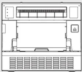
Front view diagram of a server rack unit with ventilation grilles and control panel (no text or labels)THIS OPERATION MANUAL IS IMPORTANT TO YOU.
PLEASE READ IT BEFORE USING YOUR DIGITAL COLOR PRINTER.

DIGITAL COLOR PRINTER
WARNING :
TO PREVENT FIRE OR SHOCK HAZARD, DO NOT EXPOSE THIS APPLIANCE TO RAIN OR MOISTURE.
WARNING:
Use the included AC power cord so as not to interfere with radio and television reception. If you use other cables, it may cause interference with radio and television reception.
CAUTION
RISK OF ELECTRIC SHOCK DO NOT OPEN

CAUTION : TO REDUCE THE RISK OF ELECTRIC
SHOCK, DO NOT REMOVE COVER (OR BACK) NO USER-SERVICEABLE PARTS INSIDE REFER SERVICING TO QUALIFIED SERVICE PERSONNEL.
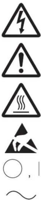
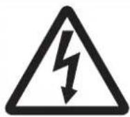
The lightning flash with arrowhead symbol, within an equilateral triangle, is intended to alert the user to the presence of uninsulated “dangerous voltage” within the product’s enclosure that may be of sufficient magnitude to constitute the risk of electric shock.
The exclamation point within an equilateral triangle is intended to alert the user to the presence of important operating and maintenance (servicing) instructions in the literature accompanying the appliance.
The “Caution, hot surface” symbol indicates that the marked item may be hot and should not be touched.
The "Electro Static Discharge (ESD) warning" symbol indicates that trouble (including equipment malfunction) due to static electricity may occur in certain conditions.
The "OFF/ON" symbol indicates connection to or disconnection from the mains, at least for mains switches.
The “Alternating current” symbol indicates that the equipment is suitable for alternating current only.
CAUTION:
Changes or modifications not expressly approved by the party responsible for compliance could void the user's authority to operate the equipment.
NOTE:
This equipment has been tested and found to comply with the limits for a Class A digital device, pursuant to Part 15 of the FCC Rules. These limits are designed to provide reasonable protection against harmful interference when the equipment is operated in a commercial environment. This equipment generates, uses, and can radiate radio frequency energy and, if not installed and used in accordance with the instruction manual, may cause harmful interference to radio communications. Operation of this equipment in a residential area is likely to cause harmful interference in which case the user will be required to correct the interference at his or her own expense.
This device complies with Industry Canada's licence-exempt RSSs. Operation is subject to the following two conditions:
(1) This device may not cause interference; and
(2) This device must accept any interference, including interference that may cause undesired operation of the device.
WARNING:
In the USA or Canada, use the AC power cord according to the recommendations as below, in order to comply with UL60950-1 and CAN/CSA C22.2 No. 60950-1-03.
Connect to the 120 V receptacle of the room or the host equipment.
The AC power cord should be UL or CSA approved and consist of type SVT, size 16 or 18AWG, length 2 m or shorter cord with IEC60320-1/C13 type, 125 V 10 A or higher rating connector and NEMA 5-15 type, 125 V 10 A or higher rating plug.
Use the AC power cord as specified above, so as not to interfere with radio and television reception.
If you use other cables, it may cause interference with radio and television reception.

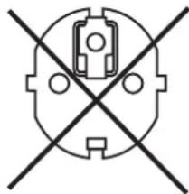
natural_image
Pure electrical circuit lines without any symbolsWARNING:
In Europe, use the AC power cord according to the recommendations as below, in order to comply with EN60950-1.
Connect to the 230 V receptacle of the room or the host equipment.
The AC power cord should be VDE approved and consist of core size 0.75 mm ^2 or bigger, length 2 m or shorter cord with IEC60320-1/C13 type, 250 V 10 A or higher rating connector and CEE(7)VII type, 250 V 10 A or higher rating plug.
Use the AC power cord as specified above, so as not to interfere with radio and television reception.
If you use other cables, it may cause interference with radio and television reception.

natural_image
Pure electrical circuit lines without any symbols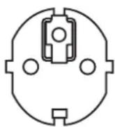

WARNING:
The socket outlet shall be installed near the equipment and shall be easily accessible.
WARNING:
This is a class A product. In a domestic environment this product may cause radio interference in which case the user may be required to take adequate measures.
This product is applicable to connect to Norwegian IT power distribution systems.
Note: This symbol mark is for EU countries only.
This symbol mark is according to the directive 2012/19/EU Article 14 Information for users and Annex IX, and/or to the directive 2006/66/EC Article 20 Information for end-users and Annex II.
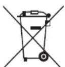
Your MITSUBISHI ELECTRIC product is designed and manufactured with high quality materials and components which can be recycled and/or reused.
This symbol means that electrical and electronic equipment, batteries and accumulators, at their end-of-life, should be disposed of separately from your household waste.
If a chemical symbol is printed beneath the symbol shown above, this chemical symbol means that the battery or accumulator contains a heavy metal at a certain concentration. This will be indicated as follows:
Hg: mercury (0,0005%), Cd: cadmium (0,002%), Pb: lead (0,004%)
In the European Union there are separate collection systems for used electrical and electronic products, batteries and accumulators.
Please, dispose of this equipment, batteries and accumulators correctly at your local community waste collection/recycling centre.
Please, help us to conserve the environment we live in!
CONTENTS .... 1
SAFETY PRECAUTIONS 2
PROTECTIVE MEASURES....2
INSTALLATION LOCATIONS .... 3
FOR LONG OPERATING LIFE....3
OTHER CAUTIONS 4
SPECIAL FEATURES ....5
UNPACKING....6
FEATURES AND FUNCTIONS....7
FRONT PANEL 7
SIDE AND REAR PANELS 8
BEFORE OPERATION 9
PRINTER SETUP PROCEDURE 9
POSITIONING OF ADJUSTABLE PAPER GUIDE 10
PRINT PAPER INSTALLATION 11
INK RIBBON INSTALLATION 13
HANDLING OF PAPER / INK RIBBON SET 15
CONNECTION WITH USB DATA SIGNAL EQUIPMENT....16
PRINTER DRIVER INSTALLATION 16
ERROR MESSAGES AND COUNTERMEASURES....17
INDICATIONS ON THE FRONT PANEL AND COUNTERMEASURES 17
OVERCOMING PAPER JAMS 18
REPAIRING A TORN INK RIBBON 19
BEFORE CALLING FOR SERVICE 20
INSTRUCTIONS FOR TRANSPORTATION....20
CLEANING....21
VENTILATION INLET CLEANING 21
THERMAL HEAD CLEANING 21
PLATEN ROLLER CLEANING 22
PAPER FLANGE CLEANING 22
SPECIFICATIONS 23
In the interest of safety, please observe the following precautions:
POWER REQUIREMENT
This Digital Color Printer is designed to operate on 100 - 240 V AC 50/60 Hz. Never connect to any outlet or power supply having a different voltage or frequency. In addition, be sure to supply power to the printer from a receptacle with a ground fault circuit interrupter.
WARNING: THIS APPARATUS MUST BE EARTHED.
PROTECTIVE MEASURES
IF ABNORMALITIES ARISE, .....
Use of the unit during emission of smoke or abnormal sounds (without adopting countermeasures) is dangerous. In such a case, unplug the power cord from the source outlet immediately, and request maintenance service from the sales dealer.
NEVER INSERT ANY OBJECT INTO THE UNIT
Foreign objects of any kind inserted into this unit constitute a safety hazard and can cause extensive damage.
DO NOT PLACE ANYTHING ON THE DIGITAL COLOR PRINTER
Heavy objects placed on the Digital Color Printer can cause damage or obstruct proper ventilation.
PROTECT THE POWER CORD
Damage to the power cord may cause fire or shock hazard. When unplugging, hold by the plug only and remove carefully.
DO NOT PLACE WATER CONTAINERS ON THE UNIT
Do not place flower vases, and other water-holding containers on the device. If, for some reason, water seeps to the inside of the unit, unplug the power cord from the source outlet, and contact the sales dealer. If used without corrective measures, the unit may be damaged.
"In the interest of safety, avoid handling of liquids near the unit."
DO NOT REMOVE THE CABINET
Touching internal parts is dangerous, besides, it may lead to malfunction. Contact the sales dealer to carry out internal checks and adjustments. Before opening the cover for eliminating a jammed paper, etc., be sure to disconnect the power cord plug.
UNPLUG THE POWER CORD DURING A LONG ABSENCE
Turn off the main power switch and unplug the power cord during a long absence.
WHEN TRANSPORTING THE UNIT
When transporting the unit, remove the ink ribbon and print paper from the unit. See "INSTRUCTIONS FOR TRANSPORTATION" on page 20.
WHEN MOVING THE UNIT
Check that the printing unit is closed firmly. And pay attention not to press the OPEN button accidentally. When the printing unit is not closed firmly or you press the OPEN button accidentally, the printing unit may open. It can cause injury or damage.
BE CAREFUL AROUND PRINT PAPER EXIT SLOT
Don't insert your hand or any material into the paper exit slot during printing.
Do not touch the cutter blade inside the paper exit slot.
Otherwise, your finger will be injured.
DO NOT TOUCH THE THERMAL HEAD EXCEPT WHEN CLEANING
Do not touch the thermal head (located inside the unit) except when cleaning.
They are heated to high temperature and may cause burns or injury when touched.
Also, malfunction caused by static electricity may occur.
WHEN PLACING THE PRINT PAPER, KEEP THE PRINT PAPER UPRIGHT
When you put the print paper sideways on a table, etc., it may roll and fall. This may cause injury.
CONNECTION CABLES
Use the provided power cord.
REMOVE THE PAPER STRIP BIN WHEN OPENING OR CLOSING THE DOOR
When you open or close the door with the paper strip bin installed, the bin may be removed and fall. This may cause injury or damage. Also, the chips generated by margin cut may jam at the paper exit slot.
DO NOT LEAVE THE PRINTING UNIT OPEN
When the printer is moved with the printing unit open, it may cause injury or damage.
CLOSE THE PRINTING UNIT FIRMLY
Take care not to pinch your hand when closing the printing unit. When the printing unit is not closed firmly, it may open during transportation and it may cause injury or damage.
DO NOT PUSH DOWN ON THE PRINTING UNIT OR THE DOOR
If you push down on the printing unit or the door when they are open, this unit may fall and it can cause damage or injury.
INSTALLATION LOCATIONS
MAINTAIN GOOD VENTILATION
Ventilation slots and holes are provided on the front, rear and both sides of this unit. Place the unit on a hard and level surface and keep a space between the unit and the walls to ensure proper ventilation. When putting the unit on the system rack, take a space between the unit and the front, back and sides of the rack.
SUITABLE LOCATIONS
Avoid shaky places or hot-springs areas where hydrogen sulfide and acidic ions are likely to be generated.
AVOID PLACES WITH HIGH HUMIDITY AND DUST
Do not place the unit at a high humidity and dusty locations. They can cause extensive damage to this unit. Avoid places where the unit is likely to be exposed to oily fumes and vapors.
AVOID PLACES LIKELY TO BE EXTREMELY HOT
Places exposed to direct sunlight, or near heating appliances can attain extremely high temperatures, which may deform the cabinet, or can become a prime cause of damage.
PLACES THE UNIT ON A HORIZONTAL LEVEL
The unit is likely to be affected if it is placed in slanted conditions or in an unstable places.
PROTECT AGAINST DEW FORMATION
In extremely cold regions, if the unit is moved quickly from an extremely cold place to warmer one, dew is likely to be formed. If dew is formed, printing is not possible.
The operating ambient temperature range is 5^ C - 40^ C ( 41^ F - 104^ F) and the humidity of 30% - 80% RH. When using the unit on the system rack, be sure to keep this ambient temperature inside the rack.
Depending on the internal temperature, it may take some time to start printing.
DO NOT STACK THE PRINTERS
Doing so may cause a printing failure due to vibrations transferred to the printers. When the printers are stacked, you cannot install or remove the ink cassette.
Coat flaking and deformation are likely to occur if the unit is wiped with chemical dusters, benzine, thinner or any other solvent, if rubber or PVC items are left in contact with the unit for extended duration, or if the unit is sprayed with insecticide.
CARE OF THE CABINET
Unplug and clean with a soft cloth slightly moistened with a mild soap and water solution. Allow to dry completely before operating. Never use petroleum base solutions or abrasive cleaners.
HEAD ABRASION
The thermal head, like the video head, wears out. When it is abraded, it becomes hard to print out fine details of the picture. In such a case, it is necessary to replace the thermal head. Consult with the sales dealer for replacing the head.
CONNECTING DEVICES
Read thoroughly "Operating Precautions" of the instruction booklets for the devices connected with the Digital Color Printer. The power cord must be disconnected after printing is over.
CAUTION ON RELOCATING
When transporting this unit, make sure it is not likely to be subjected to impacts. They can be a prime cause for damage.
Further, make sure to disconnect the power cord from the power outlet, and the cables from the connected devices.
OTHER CAUTIONS
- Do not pull out nor touch the print paper until printing is completed. It may degrade the print quality or cause an error.
- Dust or other foreign matter adhering to the print paper or the ink cassette, or deformation resulting from exposure to extremely low or high temperatures could cause loss of color, uneven color or lines, or wrinkles in the print images.
- Depending on the internal temperature, the printer may stop printing temporarily during printing. (The POWER indicator blinks green.) Please wait for the printer to resume printing.
Do not touch the print paper.
• Each time printing is completed, remove the prints. If the prints are not removed, a paper jam may occur.
• Empty the paper strip bin frequently to prevent jamming the strips at the print outlet. - The paper tray is used for storing the cut print paper (10x15 (4x6") or smaller size) temporarily. The print paper may fall from the tray or may not be stored in the printed order.
- Do not use the printer in a place where a strong wind blows. Otherwise, the print paper may not be fed properly, resulting in the paper jam.
- Do not move the printer or do not open the printing unit during printing. It may cause a printing failure.
NOTE: YOUR UNDERSTANDING IS REQUESTED FOR THE LOSS OF IMAGES IN MEMORY DUE TO THE SUDDEN OCCURRENCE OF A MALFUNCTION.
Cautions to prevent the printer from falling
CAUTION
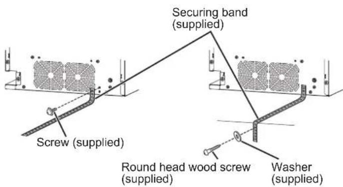
- Falling this printer due to shock or other reasons may cause injury. For your safety, make sure to secure the printer by the following procedure when you decide the location of installation of the printer.
- Secure the securing band (supplied) to the printer with the screw (supplied).
- Secure the other side of the securing band to the installation location with the round head wood screw (supplied).
AVAILABLE 5 PRINT SIZES
5 printing sizes, 9x13 (3.5x5") (max. 89 x 127 mm), 10x15 (4x6") (max. 102 x 152 mm), 13x18 (5x7") (max. 127 x 178 mm), 15x20 (6x8") (max. 152 x 203 mm) and 15x23 (6x9") (max. 152 x 229 mm), are selectable.
300 DPI HIGH RESOLUTION
CP-D90DW has a high resolution of 300 dpi for precise illustrations and sharp photographic images.
LARGE CAPACITY PRINTING
Maximum of 450 prints per roll for 9x13 (3.5x5") is offered. Large economical print capacity per roll reduces frequency of exchanging paper and ink ribbon.
HIGH QUALITY PRINTS
CP-D90DW is a dye sublimation thermal transfer color printer, which produces superior high quality images. It also produces a continuous tone at 256 gradient for each of Y, M, and C.
HIGH SPEED PRINTING
HI-SPEED USB (VER. 2.0) INTERFACE SUPPORTING
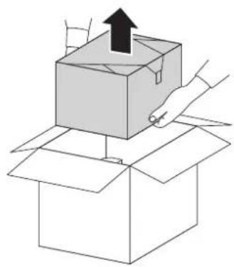
Take the printer out of the box by the following procedures. Make sure to check the accessories.
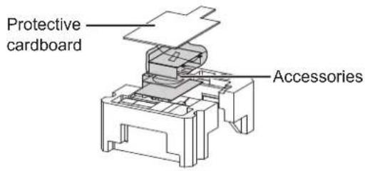
1 Open the printer box from the top and remove the top cushion containing the accessories out of the box.
Remove the protective cardboard and then take the accessories out of the cushion.
2 Carefully pull the printer up and out of the box.
Pull the printer straight up as shown in the figure.
NOTE
• The printer weighs about 14 kg. Handle it with care.
natural_image
Illustration of a hand placing an open box with an upward arrow (no text or symbols)3 Unwrap the packing.
Remove the protective materials for transportation such as protective sheet.
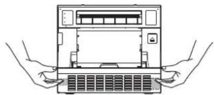
When carrying the printer, hold the handle on the left side and the recessed area on the right side as illustrated in the drawing.
CAUTION
- Do not carry the printer with the paper strip bin attached and by holding the part under the paper strip bin. The paper strip bin may be removed and fall. It may cause injury or damage.
- When the printing unit is not closed firmly or you press the OPEN button accidentally, the printing unit may open. It can cause injury or damage.
natural_image
Line drawing of two hands inserting a computer into a rack (no text or symbols)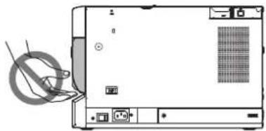
natural_image
Diagram of a computer monitor with an open rear panel and cable attachment (no text or symbols visible)CONTENTS
The accessories items are placed in the top cushion. Check all items are included.
Quick setup guide
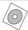
CD-ROM
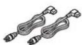
Power cords
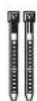
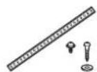
Cable ties Securing band,
Screws, Washer
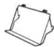
Paper tray
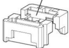


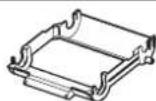
Ink cassette
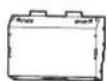
Paper strip bin
These are contained in the printer unit.
Make sure to remove the protective materials from the ink cassette and paper flanges.
FRONT PANEL
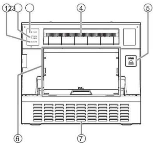
① ALARM INDICATOR (A)
This indicator illuminates or blinks when a paper jam occurs, the door is open, or the paper strip bin is removed. See page 17.
② PAPER RIBBON INDICATOR (☐/%)
When an error concerning the ink ribbon or print paper occurs, this indicator illuminates or blinks. See page 17.
③ POWER INDICATOR (∅)
When the power is turned on, the indicator illuminates. It normally illuminates green, however, blinks or illuminates orange depending on the printer status. See page 17.
④ PRINT OUTLET
The printed paper comes out here.
⑤ OPEN BUTTON ( )
Press to release the printing unit out.
⑥ PAPER STRIP BIN
Holds the paper strips generated by margin cut. Empty the bin frequently to prevent jamming the strips at the print outlet.
NOTE
- Remove the bin before opening the door. If the door is opened with this bin attached, the printer or this bin may be damaged. Do not remove the bin during printing. It may cause a malfunction.
⑦ VENTILATION INLET
This inlet is for cooling the inside of the printer.
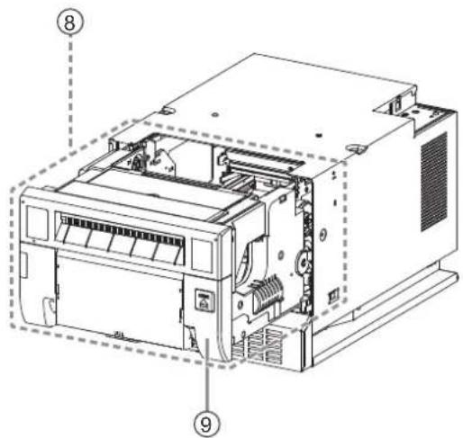
⑧ PRINTING UNIT
Open to load print paper or ink ribbon. Press the ⑤ OPEN button to release the printing unit.
⑨ DOOR
Open the door to mount print paper.
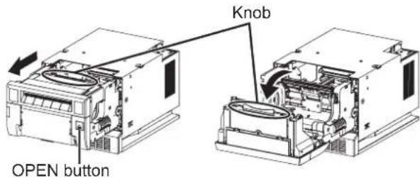
OPENING THE DOOR
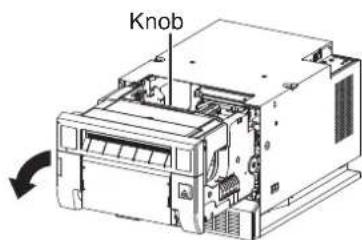
Pull out the printing unit by pressing the OPEN button and then pull the knob to open the door.
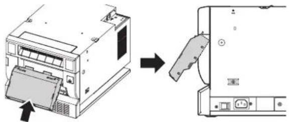
PAPER STRIP BIN
Hook and pull up the paper strip bin to attach it firmly. Hold and pull the handle on the lower part of paper strip bin to remove.
natural_image
Diagram showing a printer device being inserted into a CD-ROM drive, with no visible text or symbols.PAPER TRAY
Engage the upper hooks of the tray on the protrusions on the top of the paper strip bin (1). Then, secure the tray by engaging the lower hooks in the holes on both sides of the bin (2).
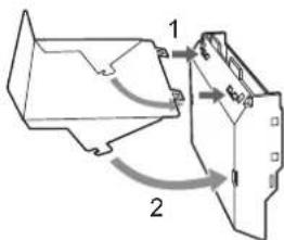
NOTE
- Remove the paper tray when printing in 13x18 (5x7"), 15x20 (6x8"), or 15x23 (6x9") size.
SIDE AND REAR PANELS
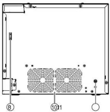
① VENTILATION INLETS
These inlets are for cooling the inside of the printer.
② DC POWER SWITCH
Enables power supply to the DC output terminal (③ or ⑪) when the switch is at the ON position and disables the power save mode condition.
③ 5 V DC OUTPUT TERMINAL USB TYPE-A (2 A MAX.)
Use to supply DC power to a small peripheral device. If the 12 V DC output terminal ( ^⑪ ) is in use, no power is supplied through this terminal. This terminal has no other function than 5 V DC supply. Connect a device designed for this printer only.
④ USB TERMINAL
Use to connect the USB cable. See page 16.
⑤ POWER SWITCH
Use to switch the power ON and OFF. After turning OFF the power, wait for approx. five seconds to turn it ON again.
⑥ POWER SOCKET (AC LINE)
Use to connect the provided power cord. Insert the cord firmly.
⑦ RECESSED AREA FOR TRANSPORTING
When carrying the printer, hold this area and the handle on the left side panel (⑨).
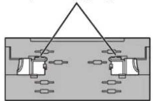
⑧ SECURING HOLES FOR THE CABLE TIE
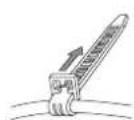
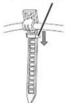
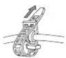
Use to secure the power cord or USB cable by using the cable ties (supplied).
⑨ HANDLE FOR TRANSPORTING
When carrying the printer, hold this handle and the recessed area on the right side panel (⑦).
⑩ VENTILATION OUTLETS
These outlets are for cooling the inside of the printer.
⑪ 12 V DC OUTPUT TERMINAL (2 A MAX.)
Use to supply DC power to a peripheral device. This terminal has a higher priority than the 5 V DC output terminal USB type-A (③). The 5 V DC output terminal USB type-A is disabled when this terminal is in use. Connect a device designed for this printer only.
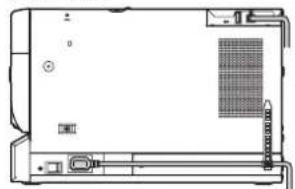
SECURING THE POWER CORD AND USB CABLE
-
Wrap a cable tie (supplied) around the power cord or the USB cable.
-
Draw the tie through the securing hole on the right side or rear panel and secure it.
(Example)
natural_image
Line drawing of a computer chassis with ventilation slots and drive unit (no text or symbols)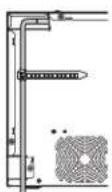
Securing hole for the cable tie
PRINTER SETUP PROCEDURE
Before printing, follow the printer setup listed below.
Position the adjustable paper guides.

(See page 10.)
Install the print paper to this printer.

(See pages 11 to 12.)
Install the ink ribbon to this printer.
(See pages 13 to 14.)
Connect the printer to a personal computer.
(See page 16.)
Make sure to close the printing unit when the setup procedure is completed.
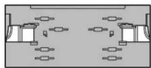
POSITIONING OF ADJUSTABLE PAPER GUIDE
Adjust the paper guides according to the paper width.
Adjustable paper guides
natural_image
Pure diagram of a symmetrical mechanical or electrical component with no text, numbers, or symbolsFor 9x13(3.5x5") or 13x18(5x7") size paper (5"-width)
natural_image
Top-down view of a symmetrical room layout with two central furniture units and four windows (no text or symbols)For 10x15(4x6"), 15x20(6x8") or 15x23(6x9") size paper (6"-width)
natural_image
Technical illustration of a mechanical device with an arrow indicating direction (no text or symbols present)■ HOW TO SET THE ADJUSTABLE PAPER GUIDES
1 Pinch the tab on the adjustable paper guide and slide it right or left.
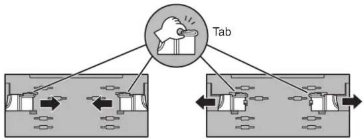
2 Slide the paper guide until it stops. The paper guide will snap into place.
3 Slide other paper guide in the similar way.
NOTE
- Make sure to set the adjustable paper guides to the size of the paper width. When they are not positioned properly, a malfunction such as paper jam and misaligned printing position may occur.
NOTE
- When you use 10x15 (4x6"), 15x20 (6x8") or 15x23 (6x9") size paper (having width of 152 mm) after using 9x13 (3.5x5") or 13x18 (5x7") size paper (having width of 127 mm) for a long time or printing such paper in large quantities, thermal head cleaning may be required. For cleaning of the thermal head, see page 21. In some cases, the print quality is not improved though thermal head cleaning is carried out. In this case, replacement of the thermal head is required. For detail, consult your dealer.
PRINT PAPER INSTALLATION
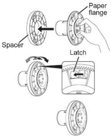
Spacers
See the Quick Setup Guide on how to use the spacers.
How to attach the spacers
- Insert the spacer with the paper flange's stoppers retracted.
- Turn the spacer until the latches are locked.
When you remove the spacers from the paper flanges, follow the above procedure in reverse.
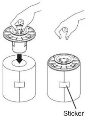
1 Attach the supplied paper flanges to both sides of the print paper.
When you pinch the latches on the paper flange, the stoppers retract into the shaft. Attach the flanges to the print paper with the stoppers retracted.
Make sure that the flanges are attached to the print paper securely, and release the latches.
NOTE
• Take care not to pinch your fingers.
- Do not remove the sticker on the print paper roll yet.
- Do not loosen the paper roll. Any slack in the print paper may degrade the print quality.
CAUTION
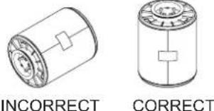
- When placing the print paper, keep the print paper upright.
- When you put the print paper sideways, it may roll and fall. This may cause injury.
NOTE
- Fingerprints or dust on the paper's surface may degrade print quality and cause paper jams.
NOTE
- When the paper flange cannot be attached due to the deformation of the print paper, reshape the print paper manually before attaching the flange.

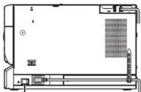
2 Press the POWER switch on the right side panel to turn on the power.
natural_image
Line drawing of a device rear panel with ports and a grid pattern on the side (no text or symbols)POWER switch
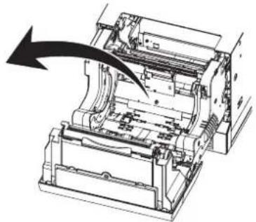
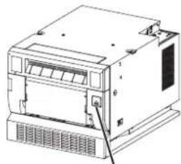
3 After the POWER indicator's color has changed from orange to green, press the OPEN button to release the printing unit out.
4 Remove the paper strip bin and then pull the knob to open the door.
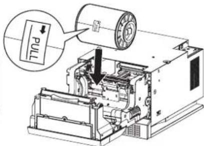
5 Install the print paper into the unit.
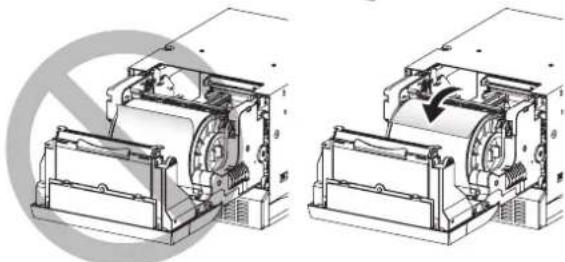
Place the printing paper in the correct orientation.
Make sure the paper roll is firmly installed.
CAUTION
- Do not push down on the printing unit or the door. If you push down on the printing unit or the door when they are open, this unit may fall and it can cause damage or injury.
NOTE
- Make sure to turn on the power before installing the print paper. Otherwise, a paper jam may occur. - Load the paper roll slowly into the unit. If it is dropped along the ditches, the unit or accessories may be damaged.
natural_image
Technical line drawing of a computer or server unit with ventilation grilles and a paper feed (no text or symbols)OPEN button
natural_image
Technical line drawings of two mechanical components with internal mechanisms and a circular annotation (no text or symbols)Direction of paper insertion
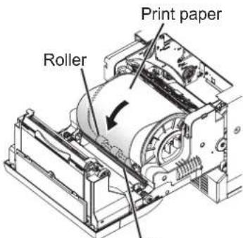
6 Remove the sticker and insert the print paper between the roller and guide as shown right to feed it. When the buzzer sounds, stop the paper feeding.
Remove the sticker before inserting the print paper between roller and guide. Make sure to insert the paper straight.
Buzzer continues to sound until the printing unit is closed.
NOTE
- Keep the rollers clean. Dirt on the rollers may produce poor print quality.
NOTE
- When taking the print paper out, pull it up toward you by holding the paper flanges.
• Make sure to turn on the power before replacing the print paper. - Make sure to eliminate any slack from the print paper. If you carry out the following steps without eliminating the slack, the print paper may be damaged.
NOTE
- If you continue to feed the print paper inward after the buzzer sounds, it may cause a paper jam.
7 Close the door.
Guide
INK RIBBON INSTALLATION
After installing the print paper, install the ink cassette into this unit.
Before installing the ink cassette into this unit, load the ink ribbon in the ink cassette.
NOTE
- Place the ink cassette on a flat surface, when loading the ink ribbon.
- Select a place that is free of dust when loading the ink ribbon. Dust or dirt settling on the ink ribbon results in poor print quality.
• Make sure that the shafts of the ink ribbon fit into the ink cassette firmly.
1 Load the ink ribbon in the ink cassette as shown below.
Make sure to load it in the correct position.
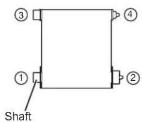
Ink ribbon
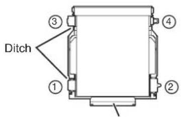
Ink cassette
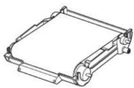
natural_image
Technical line drawing of a mechanical component with no visible text or symbolsMake sure to set the ink ribbon roller to the ditches firmly.
Turn the shaft to eliminate any slack.
2 Place the ink cassette containing the ink ribbon in the position as shown in the illustration.
To insert the ink cassette, align the protrusions on both sides of the cassette with the right and left guides inside the printing unit and slide it in a slanting direction.
Mount the ink cassette to the back firmly by holding the handle.
NOTE
- Do not touch the thermal head. Fingerprints or dust on the thermal head will degrade the print quality.
CAUTION

Do not touch the thermal head right after printing because it is extremely hot. Otherwise you may get burned or injured.
NOTE

Note that the thermal head is quite sensitive to static electricity. When you touch the thermal head while carrying static electricity on your body, the thermal head may be damaged.
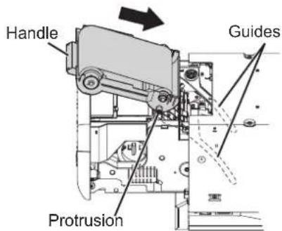
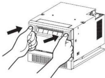
3 Push the printing unit to close.
Close the printing unit by pushing the right and left sides of the unit from the front with both hands.
When a new paper is loaded and the printing unit is closed with the power turned on, the paper will be automatically fed and cut.
CAUTION
- When closing the printing unit, be careful not to get your hands caught between the printer and the printing unit. Otherwise, you may get injured.
NOTE
- When closing the printing unit, push it until a click is heard.
- If the PAPER RIBBON indicator illuminates when the printing unit is closed, the print paper may have not been installed correctly.
In this case, open the printing unit to make sure that the print paper has been installed correctly. Then close the printing unit again. - When the paper roll is reinstalled more than three times, the print paper may be used up earlier than the ink ribbon.
Installation of the print paper and the ink ribbon is completed.
NOTE
- Make sure to replace the print paper and the ink ribbon simultaneously.
- Empty the paper strip bin frequently to prevent jamming the strips at the print outlet. Whenever you replace the paper and ink ribbon, make sure to throw away the paper strips in the paper strip bin.
- Whenever you replace the print paper and the ink ribbon, clean the thermal head and the platen roller. For the cleaning procedures, see "CLEANING" (on pages 21 and 22).
natural_image
Illustration of hands installing or adjusting a computer drive into a rack (no text or symbols visible)HANDLING OF PAPER / INK RIBBON SET
BEFORE PRINTING
- Fingerprints or dust on the paper printing surface may produce poor print quality and cause paper jams.
- When the print paper or ink ribbon is abruptly transferred from a cool place to a hot place, vapor or dew is generated on the surface, which causes paper jams or degraded print quality. Leave the print paper in the room to stabilize its temperature before use.
- If you repeat the PRINT PAPER INSTALLATION procedure more than the designated number of times, the indicated number of prints may not be made. In addition, if you replace the print paper before it is used up, the indicated number of prints may not be made.
AFTER PRINTING
- If the paper absorbs nonvolatile organic solvents (alcohol, ester, ketone, etc.) the print may be discolored.
- Discoloration of prints is accelerated if the print paper comes into contact with soft vinyl chloride such as transparent tape.
- Avoid storing prints in direct sunlight or places with high humidity.
■ STORAGE OF PAPER / INK RIBBON SET
- Do not store the print paper and ink ribbon in the container made of soft polyvinyl chloride. They may be discolored because of chemical reaction.
- Store the print paper and ink ribbon out of direct sunlight and away from heating appliances in a cool, dark place where the temperature is 5°C to 30°C and the humidity is 20% to 60% RH.
CONNECTION WITH USB DATA SIGNAL EQUIPMENT
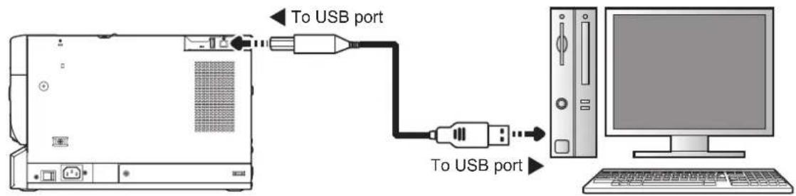
■ CONNECTING TO PERSONAL COMPUTER (EXAMPLE)
Check that the printer is turned on before connection.
1 Turn on the power of a personal computer.
2 Install the printer driver.
- Do not yet connect the printer to a personal computer.
Connect the printer to a personal computer as shown below.
Personal computerDigital color print
NOTE
- A USB cable is not supplied with this unit. Use the USB 2.0 certified cable of 2m or less in length.
PRINTER DRIVER INSTALLATION
The printer driver is required to print the data from the personal computer connected with this unit. The printer driver for Windows ^ is supplied with this unit.
Microsoft and Windows are the trademarks or the registered trademarks of Microsoft Corporation in the U.S.A. and other countries.
NOTE
• Refer to the following website to check the latest version of the printer driver and the printer information. http://www.mitsubishielectric.co.jp/ldg/ja/products/visual/lineup/printer/photo/download_01_english.html
INDICATIONS ON THE FRONT PANEL AND COUNTERMEASURES
If, for some reason, printing is not possible or an error occurs during printing, the indicators on the front panel will illuminate or blink. In this case, follow the procedure described below.

Steady on

Booking
| ALARM PAPER RIBBON POWER Causes and Countermeasures Page | ||||
| ● | ● | ○(Green) | The printer is in the standby mode. | 7 |
| ● | ● | ○(Orange) | The printer is in the power save mode.When the printer is idle for an extended period, it automatically enters the power save mode from the standby mode, reducing power consumption.It may take time that the printer is ready to print images after the image data is sent. | 7 |
| ○○● | ● | ○(Green) | The printing unit is open.• Close the printing unit. | 7 |
| ○○● | ● | ○○●(Green) | The paper strip bin is removed.• Attach the paper strip bin firmly. | 7 |
| ○○● | ○○● | ○(Green) | A paper jam or a problem concerning the ink ribbon occurs.• Refer to “Overcoming paper jams.” | 18 |
| ● | ● | ○○●(Green) | The printer is receiving image data.The temperature of the thermal head is too high or too low.• Wait until the indication goes off. When the indicator stops blinking, the printer resumes printing automatically. | 7 |
| ● | ○○● | ○(Green) | The ink ribbon which is not available to this printer is installed.• Replace the ink ribbon with a new one.The actual combination of ink ribbon and print paper is inconsistent with the setting made by the personal computer.• Open the printing unit and confirm that the actual combination of ink ribbon and print paper is consistent with the setting made by the personal computer. After checking, close the printing unit. | 13-14 |
| ● | ○ | ○(Green) | The print paper or ink ribbon is not installed.The print paper or ink ribbon is used up.• Install new print paper or ink ribbon. | 11-14 |
| ○ | ● | ○(Green) | Other errors | 20 |
When the ALARM or the PAPER RIBBON indicator illuminates or blinks, open the door and carry out the above countermeasures.
OVERCOMING PAPER JAMS
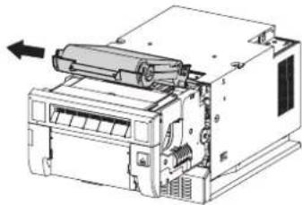
1 Press the OPEN button to open the printing unit. Make sure that the power is turned on before opening the printing unit.
2 Remove the ink cassette.
③ Remove the paper strip bin and then pull the knob to open the door.
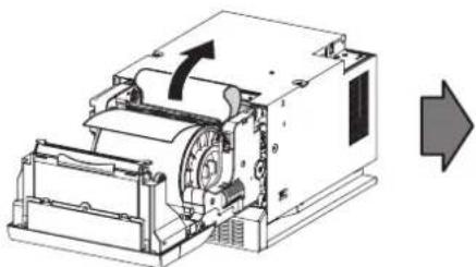
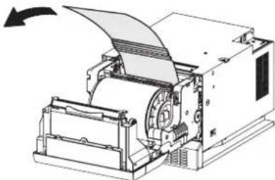
4 Pull out the defective part of the print paper to the direction of an arrow.
natural_image
Technical line drawing of a mechanical device with an arrow indicating direction (no text or symbols present)5 Cut off the defective part of the print paper with scissors.
NOTE
- Make sure to cut off the printed part of the print paper. Failure to do this may result in the ink ribbon sticking to the print paper and being torn.
- Make sure to clean the thermal head and the platen roller. Refer to "CLEANING" (on pages 21 and 22).
6 Remove the print paper.
7 Install the print paper and the ink cassette with the ink ribbon. (Refer to pages 11-15.)
Make sure that the power is turned on before installing the print paper and the ink cassette with the ink ribbon.
8 Close the door.
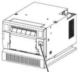
9 Close the printing unit by pushing it.
10 Attach the paper strip bin.
natural_image
Technical line drawing of a mechanical device with no visible text or symbolsOPEN button
natural_image
Technical line drawing of an electronic device with internal components and a directional arrow (no text or symbols)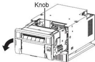
natural_image
Technical line drawing of a paper printer with paper roll and mechanical components (no text or symbols)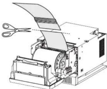
natural_image
Technical line drawing of a printer with scissors cutting through it (no text or symbols)REPAIRING A TORN INK RIBBON
1 Position the ink cassette with the torn ink ribbon on a flat, clean surface.
2 Place a piece of transparent adhesive cellophane tape on the center of the ink ribbon.
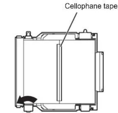
Direction to turn the shaft
3 Wind the shaft of the ink ribbon in the direction of the arrow so that the cellophane tape is not seen.
4 Install the ink cassette in the printer.
BEFORE CALLING FOR SERVICE
For the following symptoms, check the unit again before calling for service.
| Symptom | Check & Remedy |
| The power is not turned on. Is the power cord plug disconnected from the outlet?→ Connect the power cord plug to the outlet firmly.→ The protective circuit may be working. Turn off the power and wait for about two minutes. Then turn on the power again. | |
| The printing unit doesn't open. Are you turning off the power during printing procedure?→ Turn on the power and then open the printing unit. | |
| The image is not printed. Is the PAPER RIBBON indicator or the ALARM indicator illuminating or blinking?→ Refer to “Overcoming paper jams.”Is the appropriate size of data sent to this unit?→ Make sure that the appropriate size of image data is sent to this unit.Is the print paper or the ink ribbon used up?→ Check them.Is the printing unit set firmly?→ Set the printing unit firmly.→ When the indicators keep illuminating or blinking though the above operations are performed, remove the ink ribbon and print paper and reinstall them. | |
| An error can not be resolved. | → Turn off and on the power of the printer with the printing unit set firmly.This printer starts initialization.Press the switch inside of the hole of the front panel with a thin stick or the like for 5 seconds or more.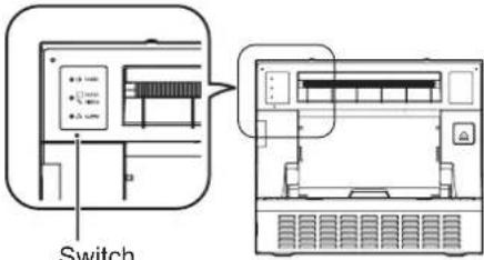 |
INSTRUCTIONS FOR TRANSPORTATION
When transporting this unit for some reason such as repair, follow the instructions below.
1. Use the original packaging.
The genuine package unit may not endure more than one round trip. If the unit is transported with the package unit more than one round trip, it may not be guaranteed.
Purchase another package unit when transporting this unit again.
Pack the unit with the accessories (ink ribbon and print paper) removed.
2. Close the printing unit firmly.
When closing the printing unit, push it until a click is heard.
CAUTION
- When the printing unit is not closed firmly or you press the OPEN button accidentally, the printing unit may open. It can cause injury or damage.
- If the ink ribbon, print paper, or ink cassette can not be taken out, consult with your dealer.
Cleaning as indicated below will help maintain stable printer operation and extend the printer's life. Wearing gloves at cleaning is recommended to prevent injury. Make sure to turn off the power before cleaning.
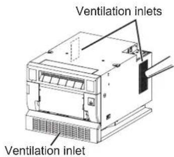
VENTILATION INLET CLEANING
Clean the ventilation inlets on the front and both sides of the printer with a vacuum as shown right.
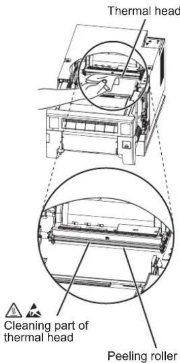
THERMAL HEAD CLEANING
1 Press the OPEN button to open the printing unit.
2 Take the ink cassette out of the printer.
Preparations
Alcohol (ethyl alcohol, etc.)
Soft and clean cloth
Other : Cleaning ribbon (option)*
* Please ask the dealer about options.
When lines appear on the printed images, clean the thermal head. Wipe the head cleaning part (as shown right) carefully with cloth dampened with a small amount of alcohol.
NOTE
- Do not damage the thermal head.
- When the poor print quality is not corrected even if the head has been cleaned, replacement of the thermal head may be required. Contact your dealer.

CAUTION
Thermal head is hot right after printing. Wait until the head cools before cleaning the thermal head.
NOTE
The thermal head may be damaged if you touch it while static electricity builds up on your body.
NOTE
- When you clean the thermal head, make sure not to apply excessive force to the peeling roller on the bottom of the thermal head. When the excessive force is applied to the roller, the roller may be deformed, resulting in deterioration of the printing quality.
■ WHEN USING THE CLEANING RIBBON (CR-D70)
When you use print paper of 152 mm (6") width after using that of 127 mm (5"), thermal head cleaning with a cleaning ribbon may be required. If one or two lines appear on the printing surface as shown in the illustration when printing on the print paper of 152 mm (6") width, clean the thermal head using the optional cleaning ribbon. Print paper of 127 mm(5") width : 9x13 (3.5x5"), 13x18 (5x7") Print paper of 152 mm (6") width : 10x15 (4x6"), 15x20 (6x8"), 15x23 (6x9")
NOTE
- When the symptom of poor print quality is not corrected even after the head is cleaned, replace the thermal head. Contact your dealer.
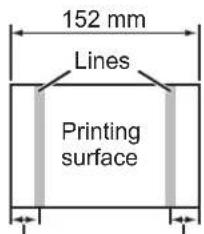
About 12 mm About 12 mm
PLATEN ROLLER CLEANING
Preparations
Alcohol (ethyl alcohol, etc.)
Soft and clean cloth
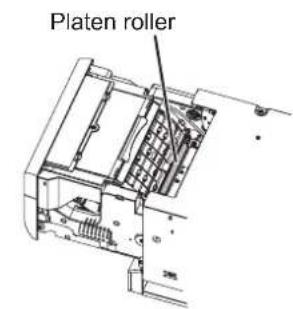
Clean the black part of the roller.
Wipe the black part carefully with cloth dampened with a small amount of alcohol.
Wipe the whole roller by turning it.
PAPER FLANGE CLEANING
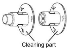
Clean the parts that contact the print paper sides as shown right.
Wipe the parts carefully with cloth dampened with a small amount of alcohol.
| Class Digital Color Printer | ||
| Model CP-D90DW | ||
| Printing method Sublimation Dye Thermal Transfer line print3-color faces progressive printing (yellow, magenta, and cyan) and surface lamination | ||
| Print's resolution 300 x 300 dpi (dpi : dots per inch) | ||
| Dot resolution 9x13 (3.5x5") | 1076 x 1550 dots | |
| 10x15 (4x6") | 1226 x 1852 dots | |
| 13x18 (5x7") | 1550 x 2128 dots | |
| 15x20 (6x8") | 1852 x 2428 dots | |
| 15x23 (6x9") | 1852 x 2729 dots | |
| Print size 9x13 (3.5x5") | 89 x 127mm (without frame) | |
| 10x15 (4x6") | 102 x 152mm (without frame) | |
| 13x18 (5x7") | 127 x 178mm (without frame) | |
| 15x20 (6x8") | 152 x 203mm (without frame) | |
| 15x23 (6x9") | 152 x 229mm (without frame) | |
| Gradations 256 (8 bits) for each color | ||
| Supply method Automatic | ||
| Interface Hi-Speed USB (Ver.2.0) | ||
| DC output terminals | 12 V / 2.0 A max. (high priority)5 V / 2.0 A max. (low priority) | |
| Power supply | 100 - 240 V AC 50/60 Hz | |
| Power consumption | 5.5 A | |
| Operating conditions Temperature : 5°C - 40°CHumidity : 30% - 80% RH (no dewing) | ||
| Installation conditions | Operating attitude : Horizontal ±5° | |
| Outside dimensions | 275 (W) x 365 (D) x 237 (H) mm | |
| Weight | Approx. 14 kg (excluding accessories) | |
| Standard accessories | Power cords (for 120 V and 230 V), Ink cassette (1), CD-ROM (1), Paper flange (1 set), Spacers (2), Quick setup guide (1), Paper strip bin (1), Paper tray (1), Cable tie (2), Securing band (1), Screw for securing band (2), Washer (1) | |
Print size and outside dimensions show typical value.
Design and specifications are subject to change without notice.
■ Contents of CD-ROM
• Operation manual
MITSUBISHI ELECTRIC US. INC.
Visual and Imaging Systems
5900-A Katella Ave.
Cypress, CA 90630-5019, U.S.A.
Phone 888-307-0309
MITSUBISHI ELECTRIC EUROPE B.V.
UK Branch
Travellers Lane, Hatfield, Herts. AL10 8XB, England, U.K.
Phone +44 (0) 1707 276100 FAX +44 (0) 1707 278755
German Branch
Gothaer Strasse 8, 40880 Ratingen ; Postfach 1548, 40835 Ratingen ; Germany
Phone +49 (2102) 486-9250 FAX +49 (2102) 486-7320
French Branch
25, Boulevard des Bouvets - 92741 NANTERRE cedex, France
Phone +33 (1) 55 68 55 00 FAX +33 (1) 55 68 57 31
Benelux Branch
Nijverheidsweg 23a,
3641 RP Mijdrecht, The Netherlands
Phone +31 (0) 297-282461 FAX +31 (0) 297-283936
Spanish Branch (Barcelona)
Manufactured by Mitsubishi Electric (Malaysia) Sdn. Bhd.
PLO 32, Kawasan Perindustrian Senai II, 81400 Senai, Johor Darul Takzim, Malaysia
- CP-D90DW
- OPERATION MANUAL
- DIGITAL COLOR PRINTER
- WARNING :
- WARNING:
- CAUTION
- CAUTION : TO REDUCE THE RISK OF ELECTRIC
- CAUTION:
- NOTE:
- POWER REQUIREMENT
- PROTECTIVE MEASURES
- IF ABNORMALITIES ARISE, .....
- NEVER INSERT ANY OBJECT INTO THE UNIT
- DO NOT PLACE ANYTHING ON THE DIGITAL COLOR PRINTER
- PROTECT THE POWER CORD
- DO NOT PLACE WATER CONTAINERS ON THE UNIT
- DO NOT REMOVE THE CABINET
- UNPLUG THE POWER CORD DURING A LONG ABSENCE
- WHEN TRANSPORTING THE UNIT
- WHEN MOVING THE UNIT
- BE CAREFUL AROUND PRINT PAPER EXIT SLOT
- DO NOT TOUCH THE THERMAL HEAD EXCEPT WHEN CLEANING
- WHEN PLACING THE PRINT PAPER, KEEP THE PRINT PAPER UPRIGHT
- CONNECTION CABLES
- REMOVE THE PAPER STRIP BIN WHEN OPENING OR CLOSING THE DOOR
- DO NOT LEAVE THE PRINTING UNIT OPEN
- CLOSE THE PRINTING UNIT FIRMLY
- DO NOT PUSH DOWN ON THE PRINTING UNIT OR THE DOOR
- INSTALLATION LOCATIONS
- MAINTAIN GOOD VENTILATION
- SUITABLE LOCATIONS
- AVOID PLACES WITH HIGH HUMIDITY AND DUST
- AVOID PLACES LIKELY TO BE EXTREMELY HOT
- PLACES THE UNIT ON A HORIZONTAL LEVEL
- PROTECT AGAINST DEW FORMATION
- DO NOT STACK THE PRINTERS
- CARE OF THE CABINET
- HEAD ABRASION
- CONNECTING DEVICES
- CAUTION ON RELOCATING
- OTHER CAUTIONS
- NOTE: YOUR UNDERSTANDING IS REQUESTED FOR THE LOSS OF IMAGES IN MEMORY DUE TO THE SUDDEN OCCURRENCE OF A MALFUNCTION.
- Cautions to prevent the printer from falling
- AVAILABLE 5 PRINT SIZES
- DPI HIGH RESOLUTION
- LARGE CAPACITY PRINTING
- HIGH QUALITY PRINTS
- HIGH SPEED PRINTING
- NOTE
- CONTENTS
- FRONT PANEL
- OPENING THE DOOR
- PAPER STRIP BIN
- PAPER TRAY
- SIDE AND REAR PANELS
- SECURING THE POWER CORD AND USB CABLE
- PRINTER SETUP PROCEDURE
- POSITIONING OF ADJUSTABLE PAPER GUIDE
- ■ HOW TO SET THE ADJUSTABLE PAPER GUIDES
- PRINT PAPER INSTALLATION
- Spacers
- INK RIBBON INSTALLATION
- Load the ink ribbon in the ink cassette as shown below.
- Place the ink cassette containing the ink ribbon in the position as shown in the illustration.
- Push the printing unit to close.
- Installation of the print paper and the ink ribbon is completed.
- HANDLING OF PAPER / INK RIBBON SET
- BEFORE PRINTING
- AFTER PRINTING
- ■ STORAGE OF PAPER / INK RIBBON SET
- CONNECTION WITH USB DATA SIGNAL EQUIPMENT
- ■ CONNECTING TO PERSONAL COMPUTER (EXAMPLE)
- PRINTER DRIVER INSTALLATION
- INDICATIONS ON THE FRONT PANEL AND COUNTERMEASURES
- OVERCOMING PAPER JAMS
- REPAIRING A TORN INK RIBBON
- BEFORE CALLING FOR SERVICE
- INSTRUCTIONS FOR TRANSPORTATION
- Use the original packaging.
- Close the printing unit firmly.
- VENTILATION INLET CLEANING
- THERMAL HEAD CLEANING
- Preparations
- ■ WHEN USING THE CLEANING RIBBON (CR-D70)
- PLATEN ROLLER CLEANING
- PAPER FLANGE CLEANING
- ■ Contents of CD-ROM
- MITSUBISHI ELECTRIC EUROPE B.V.
- UK Branch
- German Branch
- French Branch
- Benelux Branch
- Spanish Branch (Barcelona)
Brand : MITSUBISHI
Model : CP-D90DW
Category : Printer