
QuadHead2Go Q155 - Processor MATROX - Free user manual and instructions
Find the device manual for free QuadHead2Go Q155 MATROX in PDF.


| Product Type | Multi-monitor controller (standalone appliance or PCIe card) |
| Model | QuadHead2Go Q155 |
| Memory | 1 GB |
| Video Input | 1× HDMI (unit) or 1× Mini HDMI (card) |
| Video Output | 4× HDMI (unit) or 4× Mini HDMI (card) |
| Network Interface | 1× 100/1000 Base-T RJ45 Ethernet |
| Maximum Input Resolution | 3840×2160 @60Hz, 7680×1080 @60Hz, 1920×4320 @60Hz |
| Maximum Output Resolution | 1920×1080 @60Hz, 1920×1200 @60Hz |
| Color Sampling | RGB 8:8:8, YUV 4:4:4, 4:2:2, 4:2:0 (8-bit) |
| Power Consumption (Unit) | 24 W |
| Power Consumption (Card) | 15 W |
| Dimensions (Unit) | 13.97 × 3.18 × 18.11 cm (5.50 × 1.25 × 7.13 in) |
| Dimensions (Card) | 2.16 × 12.70 × 15.77 cm (0.85 × 5.00 × 6.21 in) |
| Operating Temperature | 0 to 45 °C (32 to 113 °F) |
| Operating Humidity | 20% to 80% (non-condensing) |
| HDCP Support | Yes |
| Regulatory Compliance | Class A: RCM, CE, FCC, KC |
| Key Features | Drives up to 4 displays from one source; supports bezel management, rotation, and custom layouts; software via Matrox PowerWall; firmware updatable; REST API support |
Frequently Asked Questions - QuadHead2Go Q155 MATROX
User questions about QuadHead2Go Q155 MATROX
0 question about this device. Answer the ones you know or ask your own.
Ask a new question about this device
Download the instructions for your Processor in PDF format for free! Find your manual QuadHead2Go Q155 - MATROX and take your electronic device back in hand. On this page are published all the documents necessary for the use of your device. QuadHead2Go Q155 by MATROX.
USER MANUAL QuadHead2Go Q155 MATROX
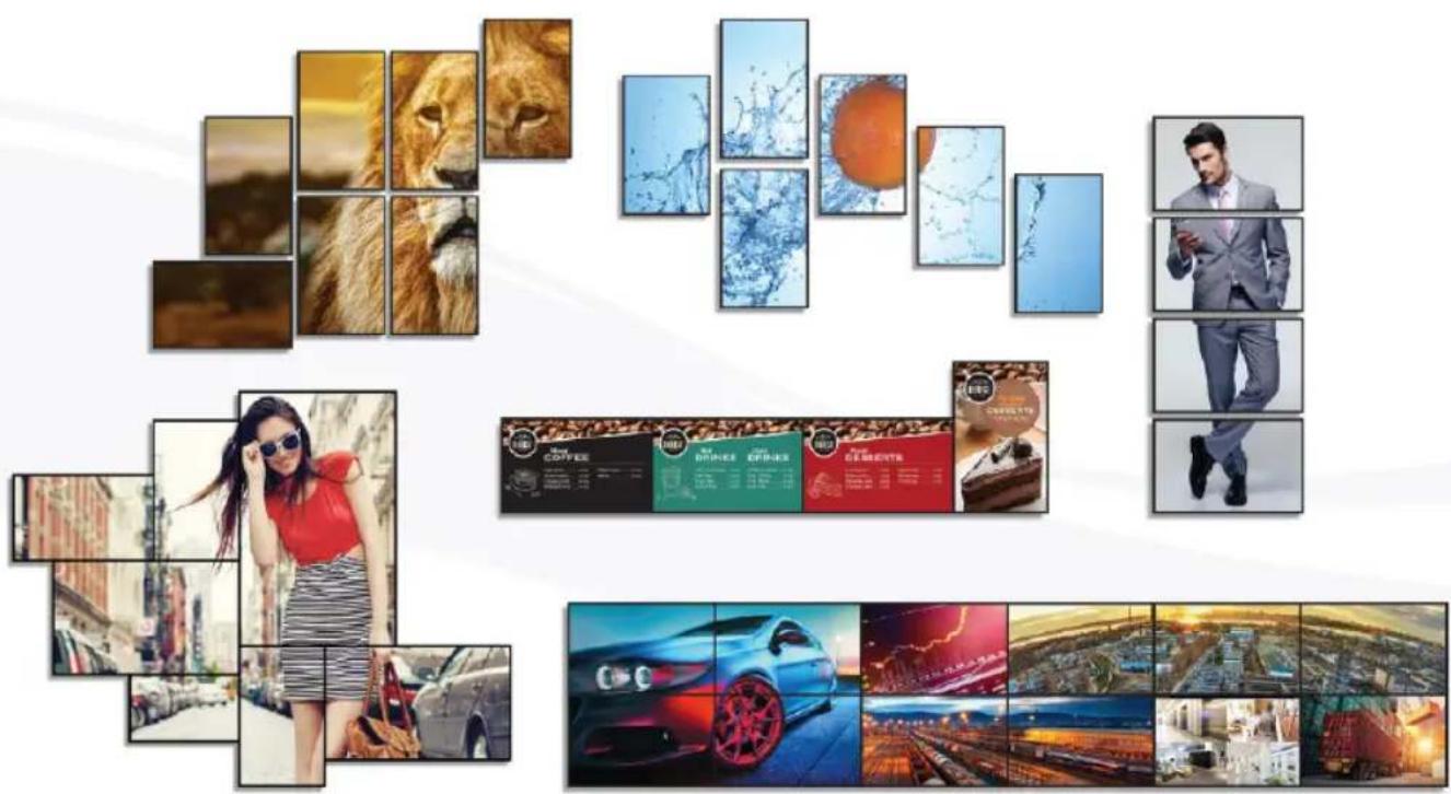
Easy-to-Deploy Video Walls.
Matrox® QuadHead2Go™ Series
QuadHead2Go Q185 • QuadHead2Go Q155
User Guide
20278-301-0110
February 27, 2020
Contents
Matrox safety information 5
Installation and operation 5
If a power supply (internal or external) was included with your product ....5
If your product includes laser-based technology ....6
If your product includes a battery ....6
Repair 6
Overview 7
Hardware supplied 7
Software available 7
Hardware required (sold separately) 7
Optional hardware (sold separately) 7
Installation overview 8
More information 8
Getting started 9
Configuration guide 9
Before you begin 9
Installing your QuadHead2Go card 10
Before you begin 10
Preventing damage to your hardware ....10
Step-by-step installation .... 10
Installing multiple cards ....11
Connecting your QuadHead2Go Q185 card 12
Before you begin 12
Connection overview 12
Description of supported connectors ....13
Step-by-step connection setup 13
Connecting your QuadHead2Go Q155 card 15
Before you begin 15
Connection overview 15
Description of supported connectors ....16
Step-by-step connection setup .... 16
Connecting your QuadHead2Go Q185 unit 18
Before you begin 18
Connection overview 18
QuadHead2Go Q185 - Back 18
Description of connectors 19
Step-by-step connection setup ....19
Connecting your QuadHead2Go Q155 unit 22
Before you begin 22
Connection overview 22
QuadHead2Go Q155 - Back 22
Description of connectors 23
Step-by-step connection setup 23
Validating your QuadHead2Go setup 25
Connection checklist 25
Description of status LEDs 25
QuadHead2Go unit 25
Network connector 26
Validating network discovery 26
Multiple subnet support 26
Updating your Matrox QuadHead2Go firmware 27
Supported operating systems 27
Obtaining the Matrox QuadHead2Go firmware updater package 27
Before you update your firmware 27
Step-by-step instructions 28
Matrox PowerWall software 30
Before you begin 30
Obtaining Matrox PowerWall software 30
Installing your software 30
Accessing Matrox PowerWall software 30
Running Matrox PowerWall .... 31
More information .... 31
Using control buttons on your QuadHead2Go device 32
Product information 34
Specifications 34
QuadHead2Go Q185 card 34
QuadHead2Go Q155 card 35
QuadHead2Go Q185 unit 36
QuadHead2Go Q155 unit 37
External power supply 38
Environmental 38
Appendix A - Matrox secure cable solution 39
QuadHead2Go card 39
Mini DisplayPort™ 39
Mini HDMI ^ 40
QuadHead2Go unit 41
Appendix B – Mounting your Matrox unit 43
Mounting guidelines 43
Mounting your QuadHead2Go unit 44
Mounting your units horizontally 44
Mounting your units vertically 44
Using your angled bracket kit 45
Mounting to a 75 or 100 mm mounting space 45
Mounting to a 200 mm mounting space 45
Customer support 46
Matrox web 46
Technical support 46
Information we need 46
Program specific problems 47
Software package download 47
View your warranty information 47
View the third party software notices 47
Register your Matrox product 47
Matrox safety information

To ensure safe and reliable operation of your Matrox product, to avoid personal injury, and to prevent damage to your computer or Matrox hardware, read the following guidelines.
Installation and operation
- Read and retain all instructions. Only use your Matrox product according to the instructions, operating ranges, and guidelines provided in the Matrox user guide and other related Matrox documentation. Failure to follow these instructions could result in damage to your product or injury to the user or installer.
- Don’t expose your Matrox product to rain, water, condensation, or moisture.
- Your Matrox product (card or unit) can become hot while operating. Always turn off your computer, unplug it, then wait for it to cool before touching any of the internal parts of your computer or installing your Matrox card. Allow hot surfaces to cool before touching your Matrox unit.

■ Static electricity can severely damage electronic parts. Before touching any electronic parts, drain static electricity from your body (for example, by touching the metal frame of your computer).
■ When handling a card, carefully hold it by its edges and avoid touching its circuitry.
- Don't stack devices or place devices so close together that they're subject to recirculated or preheated air.
- Don’t operate your system or Matrox product near a heat source or restrict airflow to your system, and make sure the ambient temperature doesn’t exceed the maximum recommended temperatures. Don’t block ventilation holes on your unit or system.
If a power supply (internal or external) was included with your product
- Don't place the external power supply directly on top of the device.
- Only use power supplies originally supplied with the product or use a replacement that's approved by Matrox. Don't use the power supply if it appears to be defective or has a damaged chassis.
- Don’t defeat the safety purpose of the polarized or grounding-type plug. A polarized plug has two blades with one wider than the other. A grounding-type plug has two blades and a third grounding prong. The wide blade or the third prong are provided for your safety. If the provided plug doesn’t fit into your outlet, consult an electrician to replace the obsolete outlet.
- Make sure that nothing rests on the power cables and that the cables aren’t located where they can be stepped on, pinched, or tripped over.
- Don't use damaged power cables.
■ Unplug your system or device during lightning storms or if unused for long periods of time.
If your product includes laser-based technology
■ The device contains a Class 1 laser product for use only under the recommended operating conditions and guidelines. For more information, see your Matrox user guide.
- Invisible laser radiation may be emitted from disconnected fibers or connectors. Don't stare into beams or view directly with optical instruments.
- Only use optical transceivers originally supplied with the product or use a replacement that's approved by Matrox.
■ For more information on laser support and compliance, see your Matrox user guide.
If your product includes a battery
■ The battery is non replaceable.
■ To dispose of your product, see www.matrox.com/environment/weee.

Repair
- Don't attempt to open or repair a power supply unit (if one was supplied).
- Don't attempt to open or repair your Matrox product.
If there's a fault with your Matrox product, review your Matrox warranty for more information.
Overview
Thank you for purchasing a Matrox QuadHead2Go Series product. Matrox QuadHead2Go products are multi-monitor controllers capable of driving a single video source on up to four displays. These controllers available as standalone appliances and PCI Express ^® cards provide complete video wall scalability and flexibility to power video walls of any type and size.
Hardware supplied\*
Depending on your QuadHead2Go Series product, the following hardware is supplied:
■ QuadHead2Go Q185 card – PCIe ^® card.
■ QuadHead2Go Q155 card – PCIe ^® card.
■ QuadHead2Go Q185 unit – Device, 1 power supply.
■ QuadHead2Go Q155 unit – Device, 1 power supply.
Software available
■ Matrox QuadHead2Go Firmware Updater
■ Matrox PowerWall
■ Matrox QuadHead2Go REST API
Hardware required (sold separately)
■ DisplayPort cable or active adapter (for your monitor type) ^†
■ Network cable (CAT 5, 5e, 6, or 7)
■ Certified HDMI® cables ^
Optional hardware (sold separately)
■ Matrox secure cable solutions
■ Matrox rack mount kit
■ Matrox angled brackets
To purchase optional hardware, contact your Matrox representative.
Installation overview
To install your Matrox product:
1 Install your QuadHead2Go card—see "Installing your QuadHead2Go card", page 10.
2 Connect your product –
- See “Connecting your QuadHead2Go Q185 card” on page 12.
- See “Connecting your QuadHead2Go Q155 card” on page 15.
- See “Connecting your QuadHead2Go Q185 unit” on page 18.
- See “Connecting your QuadHead2Go Q155 unit” on page 22.
3 Validate your setup—see “Validating your QuadHead2Go setup”, page 25.
4 Install the software – see "Matrox PowerWall software", page 30. For more information on PowerWall software, see the help file included with your PowerWall software.
More information
Your Matrox user guide provides information on installing and connecting your Matrox hardware. For information on other Matrox software features and options, see the documentation for that software.
For information on how to use and configure Matrox PowerWall software, see the PowerWall help file.
Be sure to check for any last-minute release notes included with your product. Also, check the Matrox web site (www.matrox.com/graphics) for the latest Matrox software, technical support, and product information.
Getting started
Your QuadHead2Go product has one (1) input connector (DisplayPort, Mini DisplayPort, HDMI, or Mini HDMI) and four (4) HDMI or Mini HDMI output connectors to allow you to receive a signal of up to 8K by 8K and output on up to four (4) HD HDMI monitors.

flowchart
graph TD
    A["1 2\n3 4"] --> B["Matrox®\nQuadHead2Go™"]
    B --> C["1 2 3 4"]
    C --> D["Output Module 1"]
    C --> E["Output Module 2"]
    C --> F["Output Module 3"]
    C --> G["Output Module 4"]
Configuration guide
For information on the possible display wall setups, see the Matrox QuadHead2Go Configuration Guide (www.matrox.com/quadhead2go/support).
Before you begin
We recommend you have the following:
■ DHCP (Dynamic Host Configuration Protocol) server
■ DNS (Domain Name System) server
Installing your QuadHead2Go card
This section describes how to install your Matrox card. If your Matrox card is already installed in your system, skip to “Connecting your QuadHead2Go Q185 card”, page 12 or “Connecting your QuadHead2Go Q155 card”, page 15. For information specific to your system, like how to remove its cover, see your system manual.
Before you begin
To avoid personal injury and to prevent damage to your system or Matrox hardware, read the following guidelines before installing and connecting your Matrox hardware.
Preventing damage to your hardware
■ While your system is turned off but still plugged in, some electrical current is supplied to the motherboard. This current may prevent newly installed hardware from working properly. Always try to insert or remove your card as straight as possible.
- Whenever you change your connection setup, make sure you're using the correct connectors and that all connectors are properly fastened.
■ When connecting devices, make sure the connectors are properly fastened.
■ Review the safety information provided. For more information, see “Matrox safety information”, page 5.
Step-by-step installation
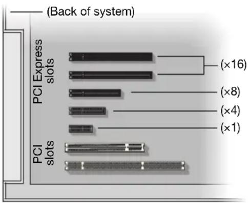
1 Choose an expansion slot
Most systems have different types of expansion slots. Choose a PCI Express® (PCIe®) slot. Your system manual should identify the location of each type of expansion slot in your system.
2 Insert your Matrox card
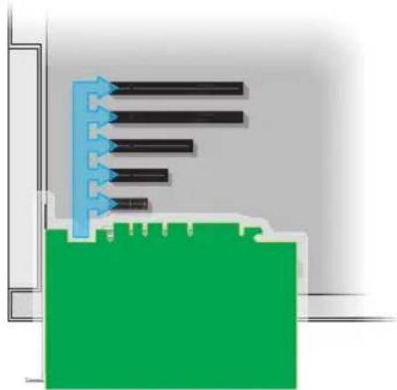
a Position your Matrox card over the expansion slot you've chosen.
b Push the card in firmly and evenly until it's fully seated in the slot.
c Secure the bracket of your Matrox card to the frame of your system.
natural_image
Pure diagram of a mechanical or electrical component with no visible text, numbers, or symbolsYour Matrox card is now installed. If you're installing more than one card, see "Installing multiple cards", page 11. Before restarting your system, connect your devices (see "Connecting your QuadHead2Go Q185 card", page 12 or "Connecting your QuadHead2Go Q155 card", page 15). After connecting, restart your system and install your Matrox software.
Installing multiple cards
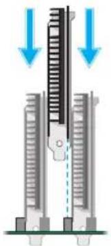
Your system may support the installation of multiple QuadHead2Go cards in your system.

WARNING: To avoid damaging your cards, always insert your card as straight as possible into the slot. Don't rock the card from side to side. If you meet resistance, don't force the card into the slot.
natural_image
Diagram of a mechanical or electrical component with downward arrows indicating force or direction (no text or symbols present)Connecting your QuadHead2Go Q185 card
This section describes how to connect your Matrox QuadHead2Go Q185 card.
Before you begin
To avoid possible problems that could damage your monitors or prevent you from using your Matrox product, read the following guidelines before connecting your devices.
- Whenever you change your connection setup, make sure you're using the correct connectors and that all connectors are properly fastened.
■ Review the safety information provided. For more information, see “Matrox safety information”, page 5.
Connection overview
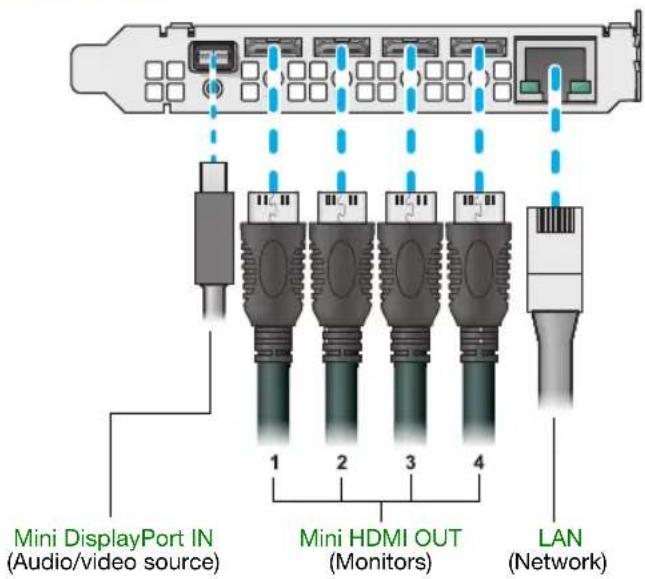
Description of supported connectors
| Connector Description | |
| Mini DisplayPort IN | Connect your mini DisplayPort cable to your Matrox card. Connect the other end of the cable to your audio/video source. |
| Mini HDMI OUT | Connect a digital monitor to this connector. |
| LAN Connect a network | work cable to this connector. |

Note: To connect to the bracket of your Matrox product, the overmold (or boot) of the mini HDMI connectors must respect the maximum width (0.551 inches/14 mm) and thickness (0.331 inches/8.4 mm) stated in the HDMI specifications.
For the mini HDMI connectors, we recommend you use certified HDMI cables that support your maximum resolution.
Step-by-step connection setup
This section guides you through the step-by-step connection setup of your QuadHead2Go card. For more information on connectors, see “Description of supported connectors”, page 13.
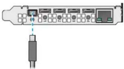
1 Connect your DisplayPort source
Connect your DisplayPort source to the mini DisplayPort connector on your QuadHead2Go card.
natural_image
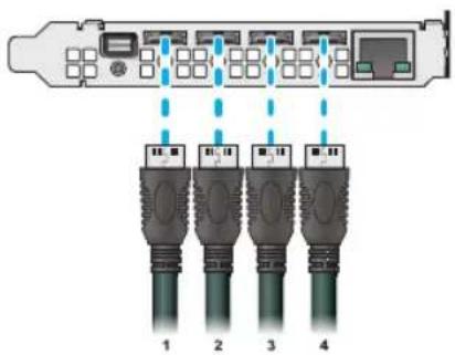
Diagram of a USB drive with ports and cable connector (no text or symbols)2 Connect your digital monitors
Connect your monitors to the mini HDMI connectors on your QuadHead2Go card.
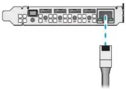
3 Connect to your network
Connect a network cable to the RJ-45 connector on your QuadHead2Go card.
natural_image
Diagram of a network device showing ports and connectors with a cable connector (no text or symbols)After connecting your QuadHead2Go card, validate your connection setup (see "Validating your QuadHead2Go setup", page 25).
Connecting your QuadHead2Go Q155 card
This section describes how to connect your Matrox QuadHead2Go Q155 card.
Before you begin
To avoid possible problems that could damage your monitors or prevent you from using your Matrox product, read the following guidelines before connecting your devices.
- Whenever you change your connection setup, make sure you're using the correct connectors and that all connectors are properly fastened.
■ Review the safety information provided. For more information, see “Matrox safety information”, page 5.
Connection overview
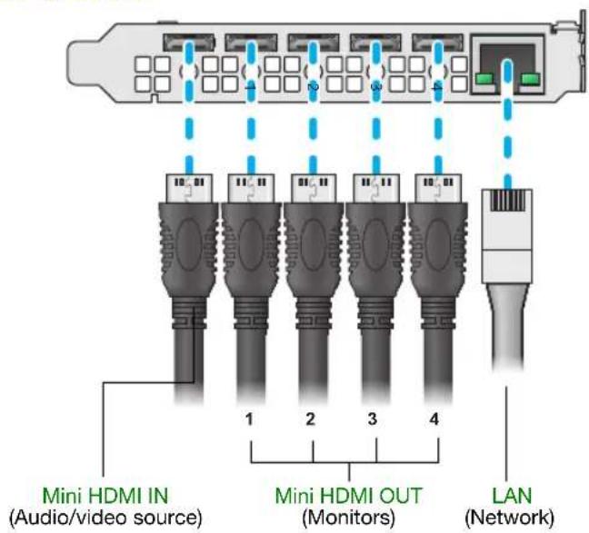
Description of supported connectors
| Connector Description | |
| Mini HDMI IN | Connect your mini HDMI cable to your Matrox card. Connect the other end of the cable to your audio/video source. |
| Mini HDMI OUT | Connect a digital monitor to this connector. |
| LAN Connect a network | work cable to this connector. |

Note: To connect to the bracket of your Matrox product, the overmold (or boot) of the mini HDMI connectors must respect the maximum width (0.551 inches/14 mm) and thickness (0.331 inches/8.4 mm) stated in the HDMI specifications.
For the mini HDMI connectors, we recommend you use certified HDMI cables that support your maximum resolution.
Step-by-step connection setup
This section guides you through the step-by-step connection setup of your QuadHead2Go card. For more information on connectors, see “Description of supported connectors”, page 16.
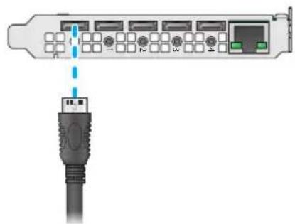
1 Connect your HDMI source
Connect your HDMI source to the mini HDMI connector on your QuadHead2Go card.
natural_image
Diagram of a USB port connector with ports numbered 1 to 4 and a connected cable (no text or symbols)2 Connect your digital monitors
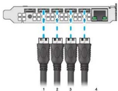
Connect your monitors to the mini HDMI connectors on your QuadHead2Go card.
3 Connect to your network
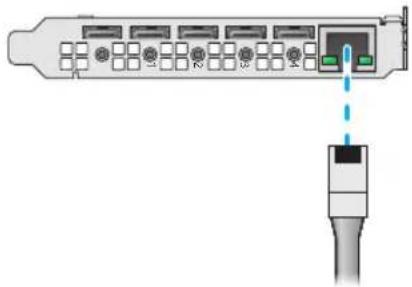
Connect a network cable to the RJ-45 connector on your QuadHead2Go card.
natural_image
Diagram of a network device showing port connections and a cable connector (no text or symbols)After connecting your QuadHead2Go card, validate your connection setup (see "Validating your QuadHead2Go setup", page 25).
Connecting your QuadHead2Go Q185 unit
This section describes how to connect your Matrox QuadHead2Go Q185 unit.
Before you begin
To avoid possible problems that could damage your monitors or prevent you from using your Matrox product, read the following guidelines before connecting your devices.
- Whenever you change your connection setup, make sure you're using the correct connectors and that all connectors are properly fastened.
■ Review the safety information provided. For more information, see “Matrox safety information”, page 5.
Connection overview
QuadHead2Go Q185 - Back
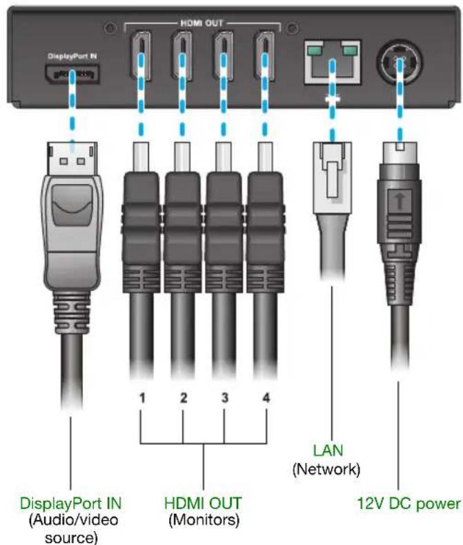
Description of connectors
| Connector Description | |
| 12V DC power | Connect the 12V DC power supply included with your product to this connector. While the power supply is connected to the device and electrical socket, the power LED ( ⏻ ) is active (not black). For more information on LEDs, see “Description of status LEDs”, page 25. |
| DisplayPort IN | Connect your DisplayPort cable to your Matrox unit. Connect the other end of the cable to your audio/video source. |
| HDMI OUT Connect | a digital monitor to this connector. |
| LAN Connect a network cable to this connector. | |

Note: To connect your monitors, the overmold (or boot) of the HDMI connectors must respect the maximum width (0.823 inches/20.9 mm) and thickness (0.452 inches/11.5 mm) stated in the HDMI specifications.
For the HDMI connectors, we recommend you use certified HDMI cables that support your maximum resolution.
Step-by-step connection setup
This section guides you through the step-by-step connection setup of your QuadHead2Go unit. For more information on connectors, see "Description of connectors", page 19.
1 Connect your DisplayPort source
Connect your DisplayPort source to the DisplayPort IN connector on your QuadHead2Go unit.
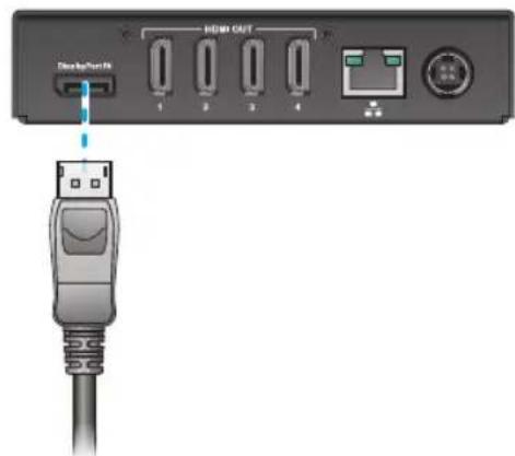

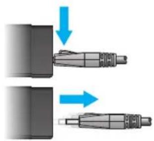
WARNING: To avoid damaging the DisplayPort connector on your DisplayPort monitor cable or on your Matrox product, carefully remove the DisplayPort cable by pressing the latch on the top of the DisplayPort connector while removing the connector.
natural_image
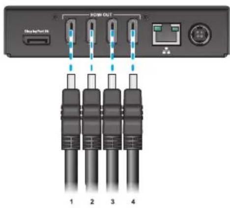
Two mechanical components with blue arrows indicating movement or assembly (no text or symbols)2 Connect your digital monitors
Connect your monitors to the HDMI OUT connectors on your QuadHead2Go unit.
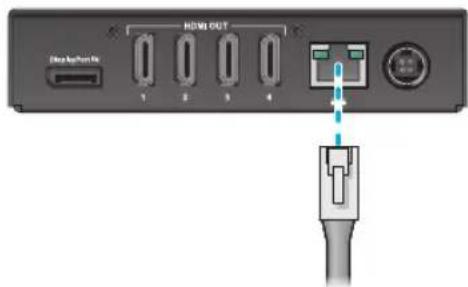
3 Connect to your network
Connect a network cable to the LAN ( **) connector on your QuadHead2Go unit.
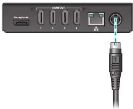
4 Connect your power supply
Connect the 12V power supply included with your product to the 12V connector on the QuadHead2Go unit.
While the power supply is connected to the unit and electrical socket, the power LED ( ) is active (not black).
For more information on LEDs, see "Description of status LEDs", page 25.

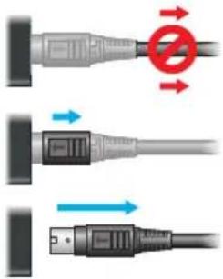
WARNING: To avoid damaging the power connector on your device or on your power cable when unplugging a unit, firmly hold the power connector, pull back the connector on the cable, then carefully remove the power cable.
After connecting your QuadHead2Go unit, validate your connection setup (see "Validating your QuadHead2Go setup", page 25).
Connecting your QuadHead2Go Q155 unit
This section describes how to connect your Matrox QuadHead2Go Q155 unit.
Before you begin
To avoid possible problems that could damage your monitors or prevent you from using your Matrox product, read the following guidelines before connecting your devices.
- Whenever you change your connection setup, make sure you're using the correct connectors and that all connectors are properly fastened.
■ Review the safety information provided. For more information, see “Matrox safety information”, page 5.
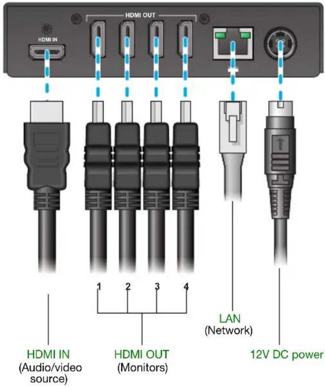
Connection overview
QuadHead2Go Q155 - Back
Description of connectors
| Connector Description | |
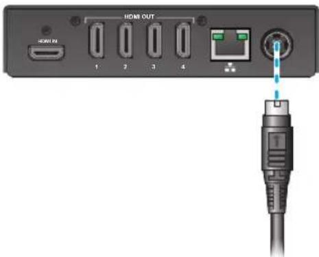
| 12V DC power | Connect the 12V DC power supply included with your product to this connector. While the 12V DC power supply is connected to the device and electrical socket, the power LED ( )ds active (not black). For more information on LEDs, see “Description of status LEDs”, page 25. |
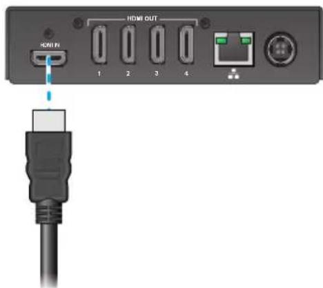
| HDMI IN | Connect your HDMI cable to your Matrox unit. Connect the other end of the cable to your audio/video source. |
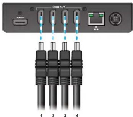
| HDMI OUT Connect | a digital monitor to this connector. |
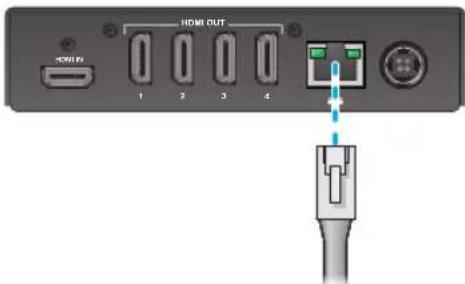
| LAN Connect a network cable to this connector. | |

Note: To connect your monitors, the overmold (or boot) of the HDMI connectors must respect the maximum width (0.823 inches/20.9 mm) and thickness (0.452 inches/11.5 mm) stated in the HDMI specifications.
For the HDMI connectors, we recommend you use certified HDMI cables that support your maximum resolution.
Step-by-step connection setup
This section guides you through the step-by-step connection setup of your QuadHead2Go unit. For more information on connectors, see "Description of connectors", page 23.
1 Connect your HDMI source
Connect your HDMI source to the HDMI IN connector on your QuadHead2Go unit.
2 Connect your digital monitors
Connect your monitors to the HDMI OUT connectors on your QuadHead2Go unit.
3 Connect to your network
Connect a network cable to the LAN (☐) connector on your QuadHead2Go unit.
4 Connect your power supply
Connect the 12V power supply included with your product to the 12V connector on the QuadHead2Go unit. While the power supply is connected to the unit and electrical socket, the power LED( ⏻ ) is active (not black).
For more information on LEDs, see "Description of status LEDs", page 25.

WARNING: To avoid damaging the power connector on your device or on your power cable when unplugging a unit, firmly hold the power connector, pull back the connector on the cable, then carefully remove the power cable.
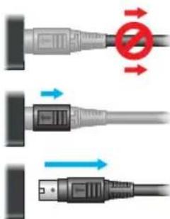
After connecting your QuadHead2Go unit, validate your connection setup (see "Validating your QuadHead2Go setup", page 25).
Validating your QuadHead2Go setup
After connecting your QuadHead2Go Series products, we recommend you validate your connection setup and network discovery before you continue.
Connection checklist
Validate the connections for your QuadHead2Go Series product:
■ See "Connecting your QuadHead2Go Q185 card" on page 12.
■ See "Connecting your QuadHead2Go Q155 card" on page 15.
■ See "Connecting your QuadHead2Go Q185 unit" on page 18.
■ See "Connecting your QuadHead2Go Q155 unit" on page 22.
Description of status LEDs
The LEDs on your QuadHead2Go products provides information to help you troubleshoot your Matrox product. The following describes the LED on your QuadHead2Go products.
QuadHead2Go unit
The two LEDS at the front of your QuadHead2Go unit provide power and status information.

Note: If LED B turns to red when a button is pressed on your QuadHead2Go unit, the buttons on your unit are disabled. For more information, see "Using control buttons on your QuadHead2Go device".
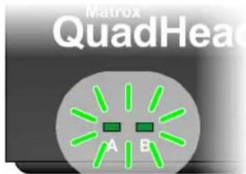
| LED color A B | ||
| No LED (black) Device isn’t powered. — | ||
| Green (solid) Device is active. Device is active. No errors. | ||
| Green (slow blink) Device is rebooting. | Input or output signal doesn’t match configuration. | |
| Green (fast blink) | Device is selected.(l-am-here feature.) | — |
| Amber (solid) | Firmware update in progress. | No input signal detected. |
| Amber (slow blink) No network detected. Firmware update in progress. | ||
| Red (solid) | Device has detected a fatal error. Try powering your device off and on. If, after restarting your device, the LEDs are still red, contact your vendor for technical support (see “Customer support”, page 46). | |
Network connector
The network connectors on your QuadHead2Go products use LEDs to provide information on the network activity and presence. The following describes the different network connector LEDs.
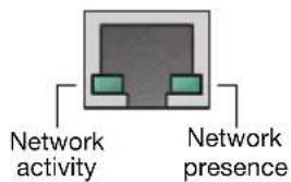
| LED color | Network activity | Network presence |
| No LED (black) | No network activity detected. | — |
| Green (fast blink) Network activity detected. | — | |
| Green | — | 1 Gbps |
Validating network discovery
QuadHead2Go Series devices are initially assigned their IP addresses through DHCP (Dynamic Host Control Protocol). After connecting your devices, we recommend verifying that all of your devices are discovered by the network. For more information, contact your network administrator.
Multiple subnet support
QuadHead2Go Series devices that are in the same subnet are detected through the UPnP (Universal Plug and Play) protocol. If your devices are in different network subnets, you need to validate network discovery in each subnet separately. For more information on using different subnets, contact your network administrator.
After validating your connection setup, install your software.
Updating your Matrox QuadHead2Go firmware
The Matrox QuadHead2Go Firmware Updater enables you to update the firmware and install the default layouts of your Matrox QuadHead2Go products.

Note: Your Matrox QuadHead2Go product may ship with an older firmware version. Before using your QuadHead2Go product, you must update the firmware version installed on your devices to use the version of your deployed release.
Supported operating systems
The Matrox QuadHead2Go Firmware Updater supports the following operating systems:
■ Windows® Server® 2019
■ Windows® Server® 2016
■ Windows® 10 (64-bit)
■ Linux (tested with Ubuntu 14.04 and Mono 5.12)
Obtaining the Matrox QuadHead2Go firmware updater package
■ Matrox makes the latest firmware and updater package for your QuadHead2Go products available on the Matrox web site (www.matrox.com/QuadHead2Go/support).
■ Download the latest firmware package and extract the files to a local folder on your system (for example, C:\QuadHead2GoFirmwareUpdate).
Before you update your firmware
Before you update the firmware on your QuadHead2Go devices, read the following guidelines:
■ Make sure you have at least 1 GB of free disk space available.
■ To avoid possible problems with your QuadHead2Go devices, we recommend running only one instance of the QuadHead2Go firmware updater on your network at a time.
■ Make sure you have a DHCP (Dynamic Host Configuration Protocol) server on an established network. The firmware updater requires constant IP addresses to update the devices properly. As the firmware updater requires a device to reboot multiple times, make sure your DHCP server maintains the IP address of a device when it reappears on the network. Otherwise, we recommend assigning fixed IP addresses to your devices.
If your system doesn't have access to a DNS server, configure your system to use a fixed IP address (such as local host – 127.0.0.1) as its DNS server. Otherwise, the firmware update process may take a long time to complete.
Step-by-step instructions
1 Run the QuadHead2Go Firmware Updater
Browse to the folder containing the extracted files, then run the UpdaterUI.exe file. This opens the QuadHead2Go Firmware Updater.
2 Search for available QuadHead2Go devices
Automatic detection – To search for the QuadHead2Go devices on your subnet, select Automatic detection.
To start searching for devices, click Search.
Manual detection – If devices aren't automatically detected, you can manually locate one or more QuadHead2Go devices using their IP address. To manually locate the devices, select Manual detection, and under Address or URL enter the IP address of each QuadHead2Go device you want to locate.
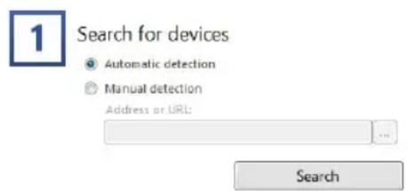
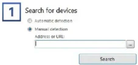
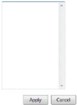
If you're entering multiple addresses, separate each address with a space. (You can also enter the IP addresses by clicking the browse button (☐) and entering one IP address per line.)
When you're done entering the IP addresses, click Apply. To discard the last changes made, click Cancel.
To start searching for devices, click Search.
To stop searching for devices, click Stop. To resume searching for devices, click Search again.
IP addresses
3 Select the devices to update
Select the devices you want to update. Devices with an older firmware version are automatically selected.
To change the sort order of the device tiles, right-click the device list box, select Sort by and the sorting order to use. To deselect all items, right-click the device list box and select Unselect all devices.
4 Update the firmware
When you're done adding QuadHead2Go devices to the list of devices you want to update, click Update.
Wait while the devices are being updated. Updating devices may take up to 10 minutes.
Matrox PowerWall software
Matrox® PowerWall™ software is available for Matrox QuadHead2Go™ multi-monitor controllers to simplify video wall designs and installations of your QuadHead2Go devices. The software works in offline mode to customize configurations of any type and size without the need for an active connection to a QuadHead2Go. Configurations are then uploaded to your physical devices.

natural_image
Abstract geometric logo composed of blue squares and a letter 'P' on black background (no text or symbols)As well as being able to configure your input and outputs resolution, you can also:
■ Rotate each output independently of the others in 90-degree increments – 90, 180, and 270 degrees – for artistic video wall configurations.
■ Control and fine-tune bezels using pre-set images to ensure seamless image displays.
■ Optimize visuals by cropping, upscaling, or downscaling the content as desired.
This section describes how to install and use Matrox PowerWall software for Windows® Server® 2016, Windows® 10 Standard (64-bit), Windows® 10 Professional (64-bit), Windows® 10 Enterprise (64-bit), and Windows® 10 IoT.
Before you begin
■ You may need administrator rights to install or uninstall certain software. For more information, see Windows documentation or contact your system administrator.
■ To assign an initial IP address to your devices, a DHCP (Dynamic Host Configuration Protocol) server is recommended.
Obtaining Matrox PowerWall software
Matrox makes the latest PowerWall software available on the Matrox web site (www.matrox.com/QuadHead2Go/support).
Installing your software
To install the software for your QuadHead2Go product, run the installation program for your software package. Follow the on-screen instructions.
Accessing Matrox PowerWall software
To access PowerWall, click Start → All apps* → Matrox PowerWall * → Matrox PowerWall. (* Depending on your configuration of Windows, this part may not be necessary.)
Running Matrox PowerWall
When PowerWall starts for the first time, a blank design is created. A design contains the devices in your video wall and their settings. To create a design, you add and remove devices. These devices are virtual because their settings aren't directly linked to a physical device.
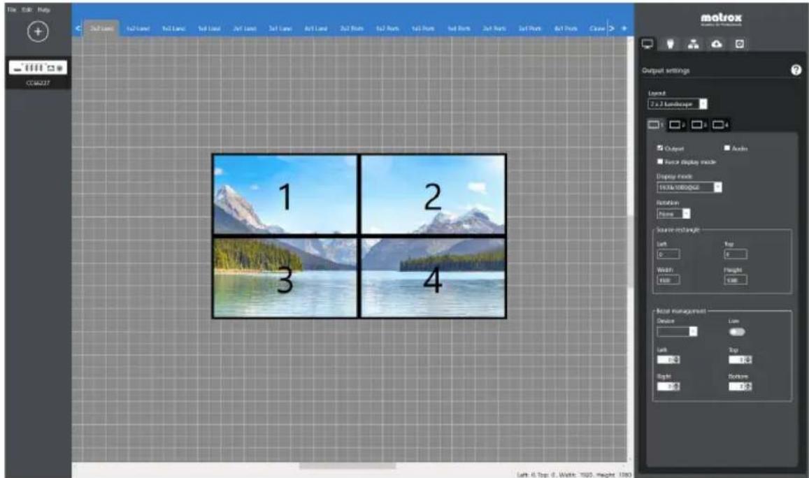
To set up your display wall design:
■ Add or remove devices from your display wall.
■ Define different layouts for the outputs of your devices using the canvas and the device output settings.
■ Select the input resolution of your device.
■ Define the network settings of your device.
■ Upload the configurations of the devices in your design to your physical QuadHead2Go devices.
More information
For more information on PowerWall software, see the help file included with your PowerWall software.
Using control buttons on your QuadHead2Go device
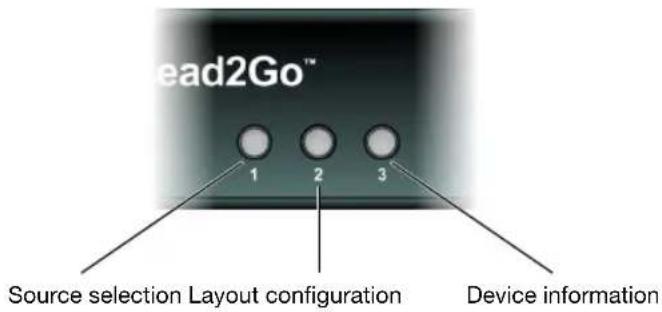
You can use the control buttons at the front of your QuadHead2Go unit and in the upper left corner on your QuadHead2Go card to select the source image, select your layout, or view information about your device.
QuadHead2Go unit
QuadHead2Go card
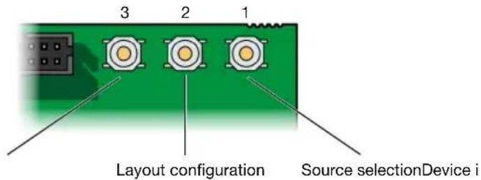
Press a control button once to view its corresponding on-screen menu. Press the button again to cycle through the menu options. Stop pressing the button to apply the current selection.
i
Note: If LED B (right) turns to red when a button is pressed on your QuadHead2Go unit, the buttons on your unit are disabled. For more information, see "Description of status LEDs".
| Button Function | |
| 1 (Source selection) | Select your input source. The following are possible input sources:Video inputLogoNature backgroundBezel adjustment gridRedGreenBlueGray gradient |
| 2 (Layout configuration) | Select your layout. The selected layout is highlighted in the list. The available layouts depend on your firmware package and can be modified through Matrox PowerWall or the QuadHead2Go REST API. |
| 3 (Device information) | Shows the device information such as:Output ID (1, 2, 3, or 4).Model number.IP address.MAC address.If IP addressing is dynamic (DHCP) or static.Active layout.Input mode.Output mode.If bezel management is enabled.If HDCP is enabled.If there is an input mismatch between the configuration and the actual signal.If there is an output mismatch between the configuration and the actual display mode.If the physical buttons on your device have been disabled.Serial number.Firmware version.FPGA version. |
| 1 and 2 (Re-enable buttons) | If the physical buttons on your device have been disabled, press and hold buttons 1 and 2 for 20 seconds to re-enable them. |
| 1 and 3 (Device reset) | Press and hold buttons 1 and 3 for five seconds to reset your device to its factory default settings. |
Product information
Specifications
QuadHead2Go Q185 card
| QuadHead2Go Q185 | |
| Operating systems supported - | |
| Product type | PCIe card (×1 electrical, ×16 mechanical - power only) |
| Form factor | Full height |
| Memory | 1 GB |
| Audio/Video input connectors | 1× Mini DisplayPort 1.2 |
| Audio/Video output connectors | 4× Mini HDMI Type C (with 16-bit stereo L-PCM audio) |
| Networking interface | 1× 100/1000 Base-T RJ45 Ethernet Port, auto-speed, half/full duplex |
| Color sampling and conversion | RGB: 8:8:8 (24-bit)YUV: 4:4:4, 4:2:2 (8-bit) |
| HDCP support √ | |
| Command protocols UPnP, HTTPS | |
| Supported maximum input resolutions * (DisplayPort video input) | 3840 × 2160 @ 60 Hz, 3840 × 2160 @ 30 Hz,7680 × 1080 @60Hz, 7680 × 1080 @30Hz,1920 × 4320 @60Hz, 1920 × 4320 @30Hz |
| Supported maximum output resolutions * (HDMI video output) †‡ | 1920 × 1080 @60Hz, 1920 × 1080 @30Hz,1920 × 1200 @60Hz, 1920 × 1200 @30Hz |
| Power consumption 15W | |
| Dimensions | 2.16 cm × 12.70 cm × 15.77 cm /0.85 inches × 5.00 inches × 6.21 inches |
| Regulatory compliance Class A: RCM, CE, FCC, KC | |
* Custom resolutions are also supported. Please contact Matrox for more details.
† When using a display resolution equal to or higher than 1280×720p60, we recommend you use certified HDMI cables that support your maximum resolution.
‡ Unless specified, modes are p60 (progressive 60 Hz).
QuadHead2Go Q155 card
| QuadHead2Go Q155 | |
| Operating systems supported - | |
| Product type | PCIe card (×1 electrical, ×16 mechanical - power only) |
| Form factor | Full height |
| Memory | 1 GB |
| Audio/Video input connectors | 1× Mini HDMI |
| Audio/Video output connectors | 4× Mini HDMI Type C (with 16-bit stereo L-PCM audio) |
| Networking interface | 1× 100/1000 Base-T RJ45 Ethernet Port, auto-speed, half/full duplex |
| Color sampling and conversion | RGB: 8:8:8 (24-bit)YUV: 4:4:4, 4:2:2, 4:2:0 (8-bit) |
| HDCP support √ | |
| Command protocols UPnP, HTTPS | |
| Supported maximum input resolutions* | 3840 × 2160 @ 60 Hz, 3840 × 2160 @ 30 Hz,7680 × 1080 @60Hz, 7680 × 1080 @30Hz,1920 × 4320 @60Hz, 1920 × 4320 @30Hz |
| (DisplayPort video input) | |
| Supported maximum output resolutions* | 1920 × 1080 @60Hz, 1920 × 1080 @30Hz,1920 × 1200 @60Hz, 1920 × 1200 @30Hz |
| (HDMI video output) †‡ | |
| Power consumption 15W | |
| Dimensions | 2.16 cm × 12.70 cm × 15.77 cm /0.85 inches × 5.00 inches × 6.21 inches |
| Regulatory compliance Class A: RCM, CE, FCC, KC | |
* Custom resolutions are also supported. Please contact Matrox for more details. We recommend you use certified HDMI cables that support your maximum resolution.
† When using a display resolution equal to or higher than 1280×720p60, we recommend you use certified HDMI cables that support your maximum resolution.
‡ Unless specified, modes are p60 (progressive 60 Hz).
QuadHead2Go Q185 unit
| QuadHead2Go Q185 | |
| Operating systems supported – | |
| Product type | Standalone appliance |
| Form factor | 1 RU, third width |
| System memory | 1 GB |
| Audio/Video input connectors | 1× DisplayPort 1.2 |
| Audio/Video output connectors | 4× HDMI Type A (with 16-bit stereo L-PCM audio) |
| Networking interface | 1× 100/1000 Base-T RJ45 Ethernet Port, auto-speed, half/full duplex |
| Color sampling and conversion | RGB: 8:8:8 (24-bit)YUV: 4:4:4, 4:2:2 (8-bit) |
| HDCP support √ | |
| Command protocols UPnP, HTTPS | |
| Supported maximum input resolutions *(DisplayPort video input) | 3840 × 2160 @ 60 Hz, 3840 × 2160 @ 30 Hz,7680 × 1080 @60Hz, 7680 × 1080 @30Hz,1920 × 4320 @60Hz, 1920 × 4320 @30Hz |
| Supported maximum output resolutions *(HDMI video output) †‡ | 1920 × 1080 @60Hz, 1920 × 1080 @30Hz,1920 × 1200 @60Hz, 1920 × 1200 @30Hz |
| Power connector§ | DIN 4 female (4-pin) |
| Power consumption 24W | |
| Dimensions | 13.97 cm × 3.18 cm × 18.11 cm /5.50 inches × 1.25 inches × 7.13 inches |
| Regulatory compliance Class A: RCM, CE, FCC, KC | |
* Custom resolutions are also supported. Please contact Matrox for more details.
† When using a display resolution equal to or higher than 1280×720p60, we recommend you use certified HDMI cables that support your maximum resolution.
± Unless specified, modes are p60 (progressive 60 Hz).
§ Only use the power supply originally supplied by Matrox with your Matrox QuadHead2Go product.
QuadHead2Go Q155 unit
| QuadHead2Go Q155 | |
| Operating systems supported – | |
| Product type | Standalone appliance |
| Form factor | 1 RU, third width |
| System memory | 1 GB |
| Audio/Video input connectors | 1× HDMI |
| Audio/Video output connectors | 4× HDMI Type A (with 16-bit stereo L-PCM audio) |
| Networking interface | 1× 100/1000 Base-T RJ45 Ethernet Port, auto-speed, half/full duplex |
| Color sampling and conversion | RGB: 8:8:8 (24-bit)YUV: 4:4:4, 4:2:2, 4:2:0 (8-bit) |
| HDCP support √ | |
| Command protocols UPnP, HTTPS | |
| Supported maximum input resolutions *(DisplayPort video input) | 3840 × 2160 @ 60 Hz, 3840 × 2160 @ 30 Hz,7680 × 1080 @60Hz, 7680 × 1080 @30Hz,1920 × 4320 @60Hz, 1920 × 4320 @30Hz |
| Supported maximum output resolutions *(HDMI video output) †‡ | 1920 × 1080 @60Hz, 1920 × 1080 @30Hz,1920 × 1200 @60Hz, 1920 × 1200 @30Hz |
| Power connector§ | DIN 4 female (4-pin) |
| Power consumption 24W | |
| Dimensions | 13.97 cm × 3.18 cm × 18.11 cm /5.50 inches × 1.25 inches × 7.13 inches |
| Regulatory compliance Class A: RCM, CE, FCC, KC | |
* Custom resolutions are also supported. Please contact Matrox for more details. We recommend you use certified HDMI cables that support your maximum resolution.
† When using a display resolution equal to or higher than 1280×720p60, we recommend you use certified HDMI cables that support your maximum resolution.
± Unless specified, modes are p60 (progressive 60 Hz).
§ Only use the power supply originally supplied by Matrox with your Matrox QuadHead2Go product.
External power supply
Input AC voltage range 100V to 240V AC
Input frequency 50 to 60 Hz
Input connector IEC 60320-C14
Output voltage 12V DC, 3.5A
Output connector DIN 4 male (4-pin) with lock
Maximum power 42W

Note: Only use the power supply originally supplied by Matrox with your Matrox QuadHead2Go product.
Environmental
Temperature, operational 0 to 45 °C (32 to 113 °F)
Temperature, non-operational storage and transportation
-40 to 70 °C (-40 to 158 °F)
Humidity, operational (indoor) 20% to 80% (non-condensing)
Humidity, non-operational storage and transportation
5% to 95% (non-condensing)
Atmospheric pressure, operational
660hPa (3,000 meters / 9,842 feet) to 1013hPa (0 meters / 0 feet)
Atmospheric pressure, non-operational and transportation
192hPa (12,000 meters / 39,370 feet) to 1020hPa (-50 meters / -164 feet)
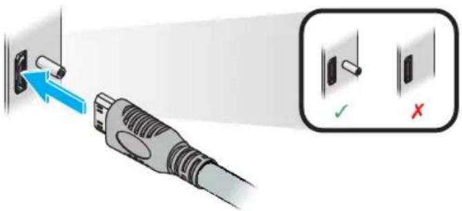
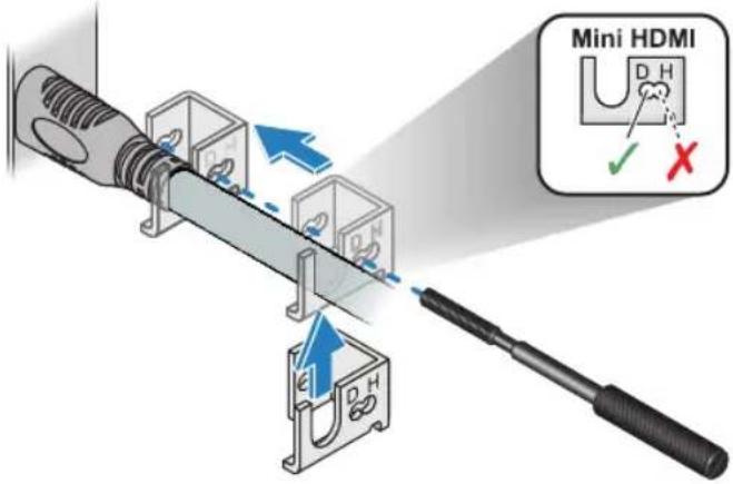
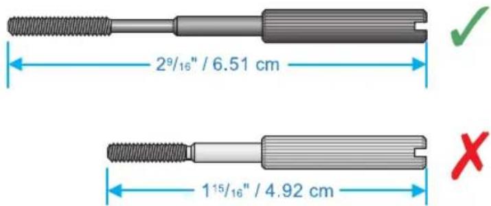
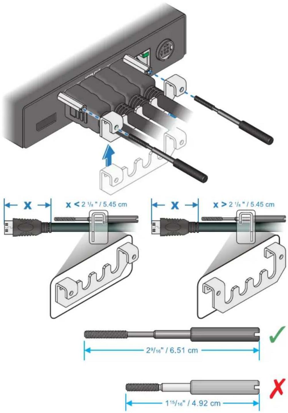
Appendix A – Matrox secure cable solution
QuadHead2Go card
Mini DisplayPort™
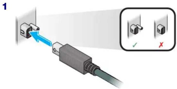
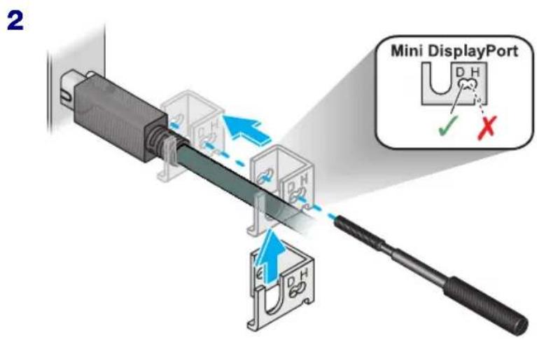

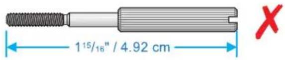
Mini HDMI®
1
2
QuadHead2Go unit
1
2
Appendix B – Mounting your Matrox unit
This section provides guidelines for rack mounting your QuadHead2Go unit.
Mounting guidelines
To prevent damage to your Matrox hardware, read the following guidelines before mounting your Matrox hardware:
- Mounting shelf only – To install your mounting shelf, fasten it to the rack as per your rack's instructions. Head screws compatible with most rack mounts are provided.
■ Mounting shelf only – The mounting shelf has existing holes for your Matrox unit that allow the shelf to be mounted facing forward or backward.
■ Use a hand screwdriver to carefully tighten each screw. Make sure to not overtighten the screws. - Don't stack anything directly over the device.
■ Make sure the cables connected to your device are properly secured and that no tension is applied to them. - Make sure the ambient temperature doesn’t exceed the maximum recommended temperatures. For more information, see “Product information”, page 34.
Once your device is mounted, you can connect your system, monitors, and devices to your Matrox device.
Mounting your QuadHead2Go unit
This section provides guidelines for mounting your QuadHead2Go unit in rack mounts using one or multiple mounting kits available from Matrox.
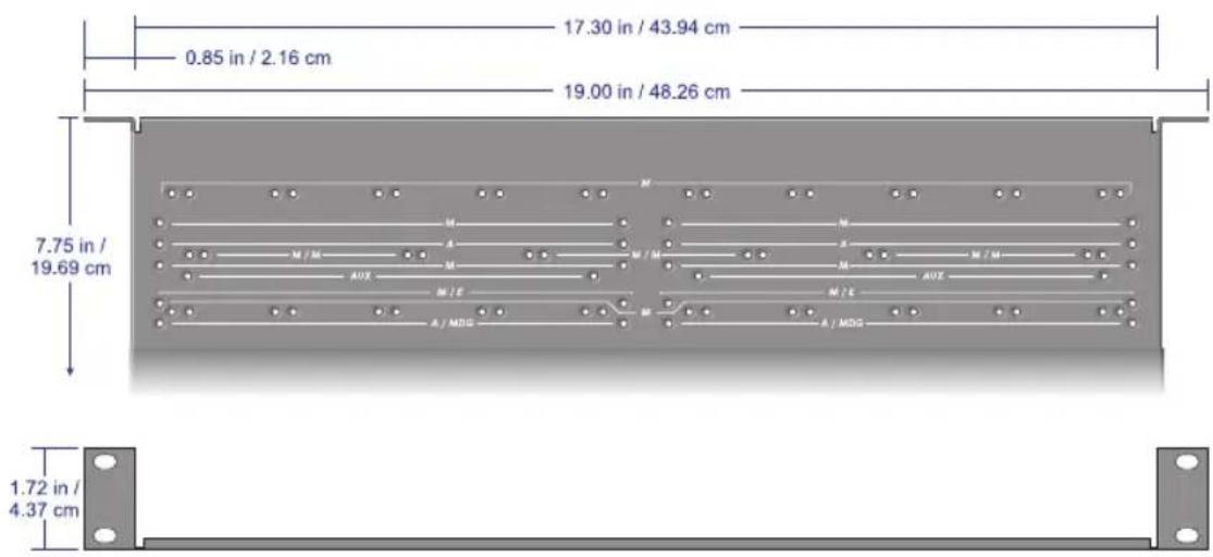
Mounting your units horizontally
Using the mounting shelf kit in a rack mount, you can mount three (3) QuadHead2Go units horizontally on a single shelf.
■ To mount your QuadHead2Go unit, use the holes labeledM/M. These holes are 2 inches / 5.08 cm from the front edge of the mounting shelf.
- Your QuadHead2Go unit has two (2) mounting holes under its casing. Use two (2) 6 mm M3 flat-head screws (included in the kit) to secure each unit.
Mounting your units vertically
Using the mounting shelf kit in a rack mount, you can mount ten (10) QuadHead2Go units vertically on a single shelf.
■ Mounting QuadHead2Go units vertically requires the height of a 3U shelf.
■ To mount your QuadHead2Go unit vertically, use the holes labeledM. These holes are 1.25 inches / 3.18 cm from the front edge of the mounting shelf.
- Your QuadHead2Go unit has two (2) mounting holes on each side. Use two (2) 6 mm M3 flat-head screws (sold separately) to secure each device to the mounting shelf. The holes used to secure the device to the shelf differ depending on which side (left or right) the device is mounted.
Using your angled bracket kit
You can mount your Matrox units on standard VESA mounts (75, 100, or 200 mm) or on the back of devices with VESA compliant mounting holes.
■ To mount your Matrox unit on a VESA mount, you need two (2) angled brackets (included in your angled bracket kit).
■ Your Matrox unit has two (2) mounting holes on each side. Use four (4) 6 mm M3 screws (included in your kit) to secure each unit to the angled brackets.
■ If a Matrox unit is attached to a VESA mount, no other device can use that VESA mount.
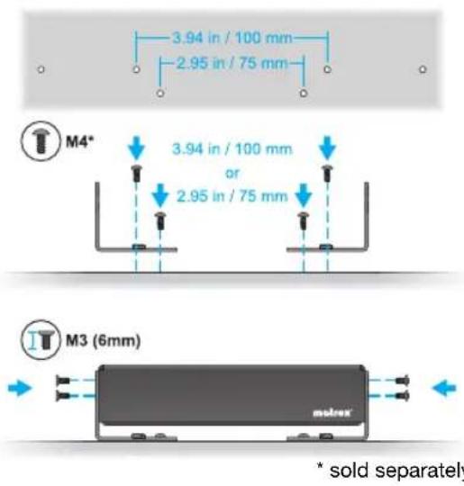
Mounting to a 75 or 100 mm mounting space
To mount your Matrox unit on a 75 or 100 mm mounting space:
■ Attach the brackets to your VESA mount before attaching your brackets to your unit.
■ Use two (2) M4 screws (sold separately) inserted through a slot in each bracket to attach your brackets to the mount.
■ Use four (4) 6 mm M3 flat-head screws (included in your kit) to attach your brackets to your unit.
Mounting to a 200 mm mounting space
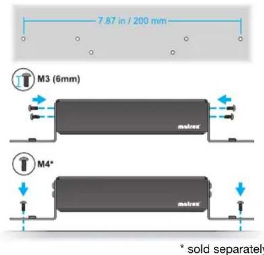
To mount your Matrox unit to a 200 mm mounting space:
■ Attach your brackets to your unit before attaching to your VESA mount.
■ Use four (4) 6 mm M3 pan-head screws (included in your kit) to attach your brackets to your unit.
■ Use two (2) M4 screws (sold separately) to attach your brackets to the mount.
Customer support
Matrox web
Our web site has product literature, press releases, technical material, a sales office list, trade show information, and other relevant material. Visit the Matrox Graphics web site at www.matrox.com/graphics.
Technical support
Matrox values your business and offers professional support for your Matrox product. If you have a problem, we recommend you follow the procedure below for the quickest results.
1 Contact your integrator – This is usually the quickest and most effective method of technical assistance. Your integrator is familiar with your complete system. In the case of hardware warranty assistance, the product must be returned to the integrator, who will return it to Matrox.
2 If your Matrox product was provided by your computer manufacturer, contact this manufacturer. For contact information, see your computer documentation or contact the vendor.
3 Direct Matrox technical support – If you still can't resolve a problem (and your Matrox product wasn't provided by your computer manufacturer), you can get technical assistance by contacting Matrox technical support at dwcsupport@matrox.com.
Information we need
Please give a complete description of the problem, and include:
■ Matrox product serial number, model number, revision number, and firmware version.
- For Matrox cards – driver type and version, and memory address at which the Matrox card is installed.
■ Computer brand and model name.
■ Monitor brand and model name.
■ Operating system, version, and service pack.
■ Brand and model of any other cards and devices installed on your system.
Program specific problems
If a problem appears with a specific program, please give us the following information:
■ Display settings (color palette, display resolution, and so on) applied when the problem occurs.
■ If possible, take note of the file and segment address that caused the problem.
■ Detailed steps known to cause the bug, so we can reproduce it.
Software package download
From your integrator or manufacturer – If your product was purchased through an integrator or a manufacturer, contact them for the latest display driver, firmware, software, and system utilities as they're familiar with your complete system. An integrator or a manufacturer may also have directives regarding software updates.
Directly from Matrox – A more recent software package may support more features and may offer increased capabilities (such as higher display resolutions). Matrox makes the latest display drivers, firmware, software, and system utilities available on the Matrox Technical Support Web site (www.matrox.com/graphics/en/support/drivers).
View your warranty information
Matrox makes warranty information available on the Matrox site (www.matrox.com/graphics/en/support/warranty).
View the third party software notices
Matrox makes third party software notices and/or additional terms and conditions available on the Matrox site (https://thirdpartylicenses.matrox.com).
Register your Matrox product
Please register online (www.matrox.com/graphics/en/registration) to receive new product announcements and information on special offers and upcoming events.
USA
FCC Compliance Statement
Remark for the Matrox hardware products supported by this guide This equipment has been tested and found to comply with the limits for a Class A digital device, pursuant to Part 15 of the FCC Rules. These limits are designed to provide reasonable protection against harmful interference when the equipment is operated in a commercial environment. This equipment generates, uses, and can radiate radio frequency energy and, if not installed and used in accordance with the instructions manual, may cause harmful interference to radio communications. Operation of this equipment in a residential area is likely to cause harmful interference in which case the user will be required to correct the interference at his own expense.
WARNING Changes or modifications to this unit not expressly approved by the party responsible for the compliance could void the user's authority to operate this equipment. The use of shielded cables for connection of the monitor to the card is required to meet FCC requirements.
CANADA
(English) Innovation, Science and Economic Development Canada
Remark for the Matrox hardware products supported by this guide These digital apparatus does not exceed the Class A limits for radio noise emission from digital devices set out in the Radio Interference Regulation of Industry Canada.
(English) European user's information – Declaration of Conformity
Remark for the Matrox hardware products supported by this guide These devices comply with EC Directive 2014/30/EU for a Class A digital device. They have been tested and found to comply with

EN55032/CISPR32 and EN55024/CISPR24. In a domestic environment these products may cause radio interference in which case the user may be required to take adequate measures. To meet EC requirements, shielded cables must be used to connect the monitor and other peripherals to the card. These products have been tested in a typical class A compliant host system. It is assumed that these products will also achieve compliance in any class A compliant system.
(English) European user's information – Directive on Waste Electrical and Electronic Equipment (WEEE)
Please refer to the Matrox Web site (www.matrox.com/environment/en/weee) for recycling information.
Advanced Micro Devices, Inc. ...... AMD®
Apple Computer, Inc. .... App Store®, Apple®, iPad®, Mac®, Mac OS®
Belden Inc. ...... Belden ®
Dolby Laboratories, Inc. .... Dolby®, Dolby Digital®
Facebook, Inc. ...... Facebook®
Google, Inc...... YouTube®
HDMI Licensing LLC ...... HDMI®
Intel Corporation Intel®
International Business Machines IBM Video Streaming™
Linus Torvalds ...... Linux®
Microsoft Corporation....Active Directory®, Aero®, Direct3D®, DirectShow®, DirectX®, Microsoft®, MS-DOS®, PowerPoint®, Windows®, Windows NT®, Windows Server®, Windows Vista®
Panopto, Inc. ...... Panopto™
PCI-SIG.... PCI™, PCI-X®, PCIe®, PCI Express®
Radio Corporation of America ...... RCA®
RealVNC Ltd. VNC®
Restream, Inc.... Restream™
Rovi Corporation...... Macrovision®
SD-3C, LLC.... SD™, SDHC™, SDXC™
Silicon Graphics, Inc. ...... OpenGL®
Silicon Image, Inc.....PanelLink®, TMDS®
Twitch Interactive, Inc. ...... Twitch™
U.S. Environmental Protection Agency...... ENERGY STAR®
Video Electronics Standards Association ...... DisplayPort™
VideoLAN ...... VideoLAN®, VLC®, VLC® media player
Vimeo, LLC ...... Vimeo®
Wibu-Systems WIBU®
Wowza Media Systems, LLC ...... Wowza™
Copyright © 1996-2020 VideoLAN. This logo or a modified version may be used or modified by anyone to refer to the VideoLAN project or any product developed by the VideoLAN team, but does not indicate endorsement by the project.
HTML5 Logo by World Wide Web Consortium (W3Q). This HTML5 logo is licensed under this Public License (http://www.creativecommons.org/licenses/by/3.0/legalcode). The logo has been modified to meet the resolution and size required by this application.
- (English) Registered trademarks are registered in the United States, Canada, and/or other countries. All other nationally and internationally recognized trademarks and tradenames are hereby acknowledged. • (Français) Les marques déposées sont déposées aux États-Unis, au Canada et/ou dans d'autres pays. Toutes les autres marques et tous les autres noms déposés reconnus nationalement ou internationalement sont également reconnus par les présentes. • (Deutsch) Die eingetragenen Warenzeichen sind in den USA, Kanada und/oder anderen Ländern registriert. Alle sonstigen national und international bekannten Warenzeichen und Produktnamen werden hiermit anerkannt. • (Italiano) I marchi registrati sono registrati negli Stati Uniti, in Canada e/o in altri paesi. Tutti gli altri marchi registrati e nomi commerciali riconosciuti a livello nazionale e internazionale sono ugualmente riconosciuti qui. • (Español) Las marcas registradas están registradas en los EE.UU., Canadá u otros países. Por medio del presente se reconocen todas las demás marcas y nombres comerciales reconocidos a nivel nacional e internacional.
(English) Disclaimer
THE INFORMATION IN THIS GUIDE IS SUBJECT TO CHANGE AT ANY TIME AND WITHOUT NOTICE.
Matrox Graphics Inc. reserves the right to make changes in specifications at any time and without notice. The information provided by this document is believed to be accurate and reliable at the time it is written. However, no responsibility is assumed by Matrox Graphics Inc. for its use, for its reproduction and/or distribution, in whole or in part; nor for any infringements of patents or other rights of third parties resulting from its use.
Dorval, Quebec, Canada H9P 2T4
(514) 822-6000
graphics@matrox.com
www.matrox.com/graphics
matrox®
Graphics for Professionals

- Easy-to-Deploy Video Walls.
- Matrox® QuadHead2Go™ Series
- Contents
- Matrox safety information 5
- Overview 7
- Getting started 9
- Installing your QuadHead2Go card 10
- Connecting your QuadHead2Go Q185 card 12
- Connecting your QuadHead2Go Q155 card 15
- Connecting your QuadHead2Go Q185 unit 18
- Connecting your QuadHead2Go Q155 unit 22
- Validating your QuadHead2Go setup 25
- Updating your Matrox QuadHead2Go firmware 27
- Matrox PowerWall software 30
- Using control buttons on your QuadHead2Go device 32
- Product information 34
- Appendix A - Matrox secure cable solution 39
- Appendix B – Mounting your Matrox unit 43
- Customer support 46
- Matrox safety information
- Installation and operation
- If a power supply (internal or external) was included with your product
- If your product includes laser-based technology
- If your product includes a battery
- Repair
- Overview
- Hardware supplied\*
- Software available
- Hardware required (sold separately)
- Optional hardware (sold separately)
- Installation overview
- More information
- Getting started
- Configuration guide
- Before you begin
- Installing your QuadHead2Go card
- Preventing damage to your hardware
- Step-by-step installation
- Choose an expansion slot
- Insert your Matrox card
- Installing multiple cards
- Connecting your QuadHead2Go Q185 card
- Description of supported connectors
- Step-by-step connection setup
- Connect your DisplayPort source
- Connect your digital monitors
- Connect to your network
- Connecting your QuadHead2Go Q155 card
- Connect your HDMI source
- Connecting your QuadHead2Go Q185 unit
- Connection overview
- Description of connectors
- Connect your power supply
- Connecting your QuadHead2Go Q155 unit
- Validating your QuadHead2Go setup
- Connection checklist
- Description of status LEDs
- QuadHead2Go unit
- Network connector
- Validating network discovery
- Multiple subnet support
- Updating your Matrox QuadHead2Go firmware
- Supported operating systems
- Obtaining the Matrox QuadHead2Go firmware updater package
- Before you update your firmware
- Step-by-step instructions
- Run the QuadHead2Go Firmware Updater
- Search for available QuadHead2Go devices
- Select the devices to update
- Update the firmware
- Matrox PowerWall software
- Obtaining Matrox PowerWall software
- Installing your software
- Accessing Matrox PowerWall software
- Running Matrox PowerWall
- Using control buttons on your QuadHead2Go device
- Product information
- Specifications
- QuadHead2Go Q185 card
- External power supply
- Environmental
- Appendix A – Matrox secure cable solution
- QuadHead2Go card
- Mini DisplayPort™
- Mini HDMI®
- Appendix B – Mounting your Matrox unit
- Mounting guidelines
- Mounting your QuadHead2Go unit
- Mounting your units horizontally
- Mounting your units vertically
- Using your angled bracket kit
- Mounting to a 75 or 100 mm mounting space
- Mounting to a 200 mm mounting space
- Customer support
- Matrox web
- Technical support
- Information we need
- Program specific problems
- Software package download
- View your warranty information
- View the third party software notices
- Register your Matrox product
- USA
- FCC Compliance Statement
- CANADA
- (English) Innovation, Science and Economic Development Canada
- (English) European user's information – Declaration of Conformity
- (English) European user's information – Directive on Waste Electrical and Electronic Equipment (WEEE)
- (English) Disclaimer
Brand : MATROX
Model : QuadHead2Go Q155
Category : Processor