
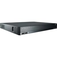
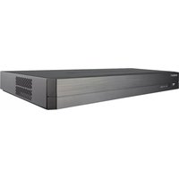
TRM-1610M - VCR Hanwha - Free user manual and instructions
Find the device manual for free TRM-1610M Hanwha in PDF.


| Product Type | Network Video Recorder (NVR) |
| Model | TRM-1610M |
| Brand | Hanwha Vision |
| Video Channels | 16 |
| HDD Support | Internal SATA HDD (expandable) |
| Power Supply | 12V DC or PoE (Power over Ethernet) |
| Network Interfaces | Dual network ports (Network 1, Network 2), Wi-Fi (external) |
| Video Output | HDMI, VGA (likely) |
| Audio Support | Yes (audio input/output) |
| PTZ Control | Yes |
| Recording Modes | Continuous, scheduled, event-triggered |
| Playback Features | Search by time, event, channel; skip forward/backward |
| Backup Options | USB, network, internal backup |
| Mobile App Support | Yes (Hanwha Vision app) |
| Installation | Wall/ceiling mount with brackets; control box for remote cameras |
| Operating Temperature | 0°C to 40°C (typical) |
| Compliance | RoHS, WEEE |
| Package Contents | Main unit, mounting brackets, power adapter, screws, manual |
| Maintenance | Clean with dry cloth; avoid liquids; ensure proper ventilation |
| Safety | Follow installation steps; use provided lock; avoid moving while holding HDD handle |
| Spare Parts | HDD, power adapter, mounting brackets, screws, keys |
Frequently Asked Questions - TRM-1610M Hanwha
User questions about TRM-1610M Hanwha
0 question about this device. Answer the ones you know or ask your own.
Ask a new question about this device
Download the instructions for your VCR in PDF format for free! Find your manual TRM-1610M - Hanwha and take your electronic device back in hand. On this page are published all the documents necessary for the use of your device. TRM-1610M by Hanwha.
USER MANUAL TRM-1610M Hanwha
Please check 'Manuals' from our website, before connecting to the Supply, https://www.HanwinaVision.com/en/data-center/download-data/video-recorder/
Package Contents

- The appearance of the components may differ from the image shown.
- Accessory category and quantity may differ depending on sales region.
TRM-1610S/1610M

TRM-410S/810S/810M

How to install the product

- The images below are based on the THM 1610S model

remove the mounting bracket and side brackets.

ighton the side brackets to the body.
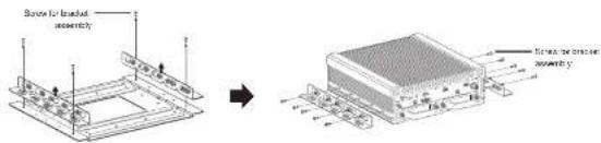

stal the mounting bracket at the installation site.

stall the main body with the side brackets in the bracket installed in Step 3.
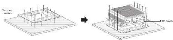

- Be sure to observe the work procedure (1 - 4) when installing the product, and pay attention to potential accidents caused by the product falling.
- When moving the set, do not move it while holding the HDD handle.
How to install the control box

- The images below are based on the TRM-161OS model.
Assemble mounting screws and install the camera on a wall/floor/ceiling as shown in the figure. Connect to the main unit via the control box connection cable.

Installing the HDD

■ The images below are based on the TRM-1610S model.
TRM-1610S/TRM-1610M
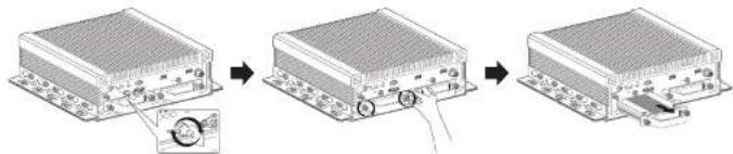
1 Unscrew the HDD bracket fixing screws on the front of the set and pull it to the front to separate the HDD. ■ If the box on the front is locked, open the lock using the key that was provided when you purchased the product.
flowchart
graph LR
    A["Device 1"] --> B["Component 1"]
    B --> C["Component 2"]
    C --> D["Component 3"]
- loosen the screws on the front/rear of the bracket and separate the bracket.
3 After replacing/installing the HDD, fix the HDD and bracket with screws.
4 Slide the bracket with the HDD into the main body, and tighten the screws to fix it.

natural_image
Technical line drawing of a multi-tiered mechanical assembly with mounting flanges and structural supports (no text or symbols)
- If you are adding a new or previously used HDD to this product in addition to the HDD(s) originally installed, format the new HDD manually in the set before use.
- For replacement or installation of an additional HDD you must contact your dealer or our customer center.
TRM-810S/TRM-810M/TRM-410S

■ The images below are based on the TRM-810S model.
1 Unscrew the HDD bracket fixing screws on the front of the set and pull it to the front to separate the HDD. - If the lock on the front is locked, open the lock using the key that was provided when you purchased the product

flowchart
graph LR
    A["Device 1"] --> B["Control Panel"]
    B --> C["Device 2"]
    C --> D["Device 3"]
2 Remove the screws from the bracket to separate the bracket.

flowchart
graph LR
    A["Device 1"] --> B["Device 2"]
    B --> C["Device 3"]
    C --> D["Device 4"]
3 After replacing/Installing the HDD, fix the HDD and bracket with screws.
4 Slide the bracket with the HDD into the main body, and tighter the screws to fix it.
- Make sure to properly place the fan connector when installing HDD.


Install Wizard
1 Select the language
Select your preferred language.
2 Set Password Set a password.

※ Click ☐ on to see the password rule. Check the password setting rules.
2-1. Setting Camera Password
You can change the password of the camera one step.
If the password of the camera is the default password set in the factory, enter a new password to change it. The password will be changed, and the new password will be registered.
If the password of the camera is not the default password set in the factory, enter the current camera password. The current camera password will be registered.
- New Password : Input a new password according to the password setting rules.
- Confirm Password: Input the new password again.
- A camera password registered with OKVF and RTSP cannot be changed.
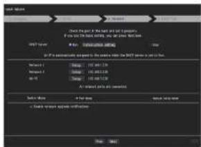
3 Set up Network
- DHCP server : If the DHCP server is set to enable, an IP is automatically assigned to the camera.
• Network 1: Connects to the camera and receives the video feed from the camera.
• Network 2: This is a port for transmitting an image to the webviewer.
- Wi-Fi : Port for connecting to external Wi-Fi. The Wi-Fi port is used for backup.
• Network 1 / Network 2 Setup
- IP Type : Choose the network connection method.
- IP Address, Subnet Mask, Gateway, DNS
- Wi-Fi can be set after the installation wizard has been closed.
※ For more details on network settings, refer to the User manual.
▶ To use a simple intranet, click
- Switch Mode: Set the camera registration method. This function is only available for products with PoE support.
For products with PoE support, see "NVR products supporting each feature". (Page 4)
- PnP Mode: Camera connected to the PoE port of the product will be registered automatically on each channel in the order of the port number.
This works only when camera is in factory reset state.
- Manual Setup Mode: Automatically scans and registers camera connected to the product's PoE and camera with separate switch.

4 Set Date & Time
Set the time and date and click the
5 Camera Registration
In the setting completion window, click on the
5-1. Cameras connected to the PoE port are automatically registered and displayed in the camera registration list. Select the cameras to be registered from the list of cameras, and click the
The camera may not be shown in the list if there is no response from the camera. You can re-import the list by pressing the

5-2. When camera registration is finished, the frame rate of the set recording profile is displayed. After you click the


Configure and run layout
You can use the same layout set on the live screen for the Search Time function in order to perform a search using the channel sequence and combination configured by the user.

- For more information about the detailed selling method for each stage, refer to the user manual.

ive channel layout settings


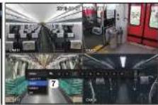
① Open the channel layout setup menu.
2 Click
3 Enter a name for the selected channels (e.g., Indoor).
4) Select the channels that you want to add to the layout (e.g., 1, 2, 3, 4).
5 Choose a split mode to apply (e.g., 4-way split).
6 Click
7 Choose a layout to view it on the screen (e.g., change to indoor).


1 In live mode, right-click to select

Search

- The initial search option is set to
. Select a desired layout from among the channel group created in the live screen.
2 Select a channel for each selected group. - Move the time bar to view the preview screen as shown in Figure 4.
5 Press thebutton to enter the play screen.

Play

natural_image
Interior view of a train carriage with passengers, a red train, and a digital display panel (no visible text or symbols)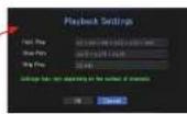
- These are the various functions available for playback. Hover over them and a tool tip will be prompted. Control the playback by referring to the tool tip. (Ex : Skip Backward)
- You can configure specific functions in 1 through playback settings. Ex) Jump to play: 10 minutes, 30 minutes, 1 hour, 24 hours, etc.
3 Displays functions that are operating in split mode and during other playback.

ackup
Right-click on the live screen and select

1 Select a layout.
2 Select a channel.
3 Set the time, device, and format to back up.
4. Click the
5. Click the
Use the basic guide
Show shortcut menu
Right-click on the live screen and you can access various functions that NVR provides. Hover over an icon and a brief definition of term for each function is prompted.

flowchart
graph TD
    A["Layout Setup"] --> B["Keep ch. scr ratio"]
    B --> C["Status"]
    C --> D["PTZ"]
    D --> E["ZOOM"]
    E --> F["Audio"]
    F --> G["Freeze"]
    G --> H["Stop Alarm"]
    H --> I["Capture"]
    I --> J["Record"]
    J --> K["Play"]
    K --> L["Search"]
    L --> M["Backup"]
    M --> N["Menu"]
    N --> O["Shutdown"]
    O --> P["Logout"]
    P --> Q["Hide Launcher"]
    R["Setup"] --> S["User Time Language"]
    S --> T["Video"]
    S --> U["Audio/Video/Video"]
    S --> V["Cloud"]
    S --> W["Network"]
Live launcher

① You can configure a live layout.
(2) You can configure a supported split mode. You can view the end sequence (1) in serial order for a specific period of time for each split mode.
3) You can configure additional functions in the live screen, such as alarm control or audio.
Use product information
You can check product information/user manual/firmware information/FAQ/HDD compatibility list, etc. on the website or mobile app on your smartphone.



Hanwha Vision cares for the environment at all product manufacturing stages, and is taking measures to provide customers with more environmentally friendly products.
The Eco mark represents Harwha Vision's devotion to creating environmentally friendly products, and indicates that the product satisfies the EU RoHS Directive.
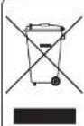
Correct Disposal of This Product (Waste Electrical & Electronic Equipment)
Applicative in the European Union and other European countries with separate collection systems
This working on the product, accessories or literature indicates that the product and its electronic accessories (e.g. charger, heater, USB cable) should not be disposed of with other household waste at the one of their working life, to prevent possible harm to the environment, or human health from uncontrolled waste disposal presses separate these items from other types of waste and recycle them responsibly to promote the sustainable reuse of material resources.
Household users should contact either the retailer where they purchased this product, or their local government office, for details of where and how they can take these items for environmentally safe recycling.
Business users should contact their supplier and check the terms and conditions of the purchase contract. This product and its electronic accessories should not be mixed with other commercial access for disposal.

Correct disposal of batteries in this product
Applicable in the European Union and other European countries with separate battery return systems.
This morning on the battery, manual or packaging indicates that the batteries in this product should be disposed of with other household waste in the end of their working life. Where market, the chemical symbols Hg. Color Prin indicate that the battery contains mercury, potassium or lead above the reference levels in PC Directive 2036-66. It batteries are not properly disposed of, these substances can cause harm to human health or the environment.
to protect natural resources and to promote material reuse, please separate batteries from other types of waste and recycle them through your local, free battery return system.

Hanwha
Vision



- Package Contents
- TRM-1610S/1610M
- TRM-410S/810S/810M
- How to install the product
- How to install the control box
- Installing the HDD
- TRM-1610S/TRM-1610M
- TRM-810S/TRM-810M/TRM-410S
- Install Wizard
- Select the language
- Set Password Set a password.
- 2-1. Setting Camera Password
- Set up Network
- Set Date & Time
- Camera Registration
- Configure and run layout
- Use the basic guide
- Show shortcut menu
- Live launcher
- Use product information
- Correct Disposal of This Product (Waste Electrical & Electronic Equipment)
- Correct disposal of batteries in this product
Brand : Hanwha
Model : TRM-1610M
Category : VCR