Integrated 225 - Receiver Anthem - Free user manual and instructions
Find the device manual for free Integrated 225 Anthem in PDF.


| Product Type | Integrated Amplifier / Stereo Receiver |
| Brand | Anthem |
| Model | Integrated 225 |
| Power Output | 225W per channel into 8 ohms |
| Frequency Response | 20 Hz - 20 kHz ±0.1 dB |
| Total Harmonic Distortion | <0.003% |
| Signal-to-Noise Ratio | 115 dB (A-weighted) |
| Inputs | 5x RCA, 1x XLR, 1x Phono (MM) |
| Outputs | Speaker terminals, Pre-out, Headphone |
| Speaker Impedance | 4 - 16 ohms |
| Dimensions (W x H x D) | 17.0 x 6.5 x 15.0 inches (432 x 165 x 381 mm) |
| Weight | 28 lbs (12.7 kg) |
| Power Consumption | 600W (max), <0.5W standby |
| Remote Control | Included (IR) |
| Color | Black or Silver |
| Warranty | 5 years (USA/Canada), 2 years international |
| Cleaning Instructions | Wipe with a soft, dry cloth. Avoid liquids and abrasives. |
| Safety Precautions | Do not expose to moisture or extreme temperatures. Disconnect when not in use for extended periods. |
| Serviceability | Contact authorized Anthem service center for repairs. No user-serviceable parts inside. |
Frequently Asked Questions - Integrated 225 Anthem
User questions about Integrated 225 Anthem
0 question about this device. Answer the ones you know or ask your own.
Ask a new question about this device
Download the instructions for your Receiver in PDF format for free! Find your manual Integrated 225 - Anthem and take your electronic device back in hand. On this page are published all the documents necessary for the use of your device. Integrated 225 by Anthem.
USER MANUAL Integrated 225 Anthem
The lightning flash with arrowpoint within an equilateral triangle warns of the presence of uninsulated “dangerous voltage” within the product’s enclosure that may be of sufficient magnitude to constitute a risk of electric shock to persons.

The exclamation point within an equilateral triangle warns users of the presence of important operating and maintenance (servicing) instructions in the literature accompanying the appliance.
WARNING: TO REDUCE THE RISK OF FIRE OR ELECTRIC SHOCK, DO NOT EXPOSE THIS PRODUCT TO RAIN OR MOISTURE AND OBJECTS FILLED WITH LIQUIDS, SUCH AS VASES, SHOULD NOT BE PLACED ON THIS PRODUCT.
CAUTION: TO PREVENT ELECTRIC SHOCK, MATCH WIDE BLADE OF PLUG TO WIDE SLOT, FULLY INSERT.
CAUTION: FOR CONTINUED PROTECTION AGAINST RISK OF FIRE, REPLACE THE FUSE ONLY WITH THE SAME AMPERAGE AND VOLTAGE TYPE. REFER REPLACEMENT TO QUALIFIED SERVICE PERSONNEL.
WARNING: UNIT MAY BECOME HOT. ALWAYS PROVIDE ADEQUATE VENTILATION TO ALLOW FOR COOLING. DO NOT PLACE NEAR A HEAT SOURCE, OR IN SPACES THAT CAN RESTRICT VENTILATION.
IMPORTANT SAFETY INSTRUCTIONS
- Read Instructions – All the safety and operating instructions should be read before the product is operated.
- Retain Instructions – The safety and operating instructions should be retained for future reference.
- Heed Warnings – All warnings on the product and in the operating instructions should be adhered to.
- Follow Instructions – All operating and use instructions should be followed.
- Cleaning – Unplug this product from the wall outlet before cleaning. Do not use liquid cleaners or aerosol cleaners. Use a damp, soft cloth for cleaning.
- Water and Moisture – Do not use this product near water – for example, near a bath tub, wash bowl, kitchen sink, or laundry tub; in a wet basement; or near a swimming pool; and the like.
-
Accessories – Do not place this product on an unstable cart, stand, tripod, bracket, or table. The product may fall, causing serious injury to a child or adult, and serious damage to the product. Use only with a cart, stand, tripod, bracket, or table recommended by the manufacturer, or sold with the product. Any mounting of the product should follow manufacturer's instructions, and should use a mounting accessory recommended by the manufacturer.
-
Ventilation – Slots and openings in the cabinet are provided for ventilation and to ensure reliable operation of the product and to protect it from overheating, and these openings must not be blocked or covered. The openings should never be blocked by placing the product on a bed, sofa, rug, or other similar surface. This product should not be placed in a built-in installation such as a bookcase or rack unless proper ventilation is provided or the manufacturer's instructions have been adhered to.
-
Power Sources – This product should be operated only from the type of power source indicated on the marking label. If you are not sure of the type of power supply to your home, consult your product dealer or local power company. For products intended to operate from battery power, or other sources, refer to the operating instructions.
-
Grounding and Polarization – This product may be equipped with a polarized alternating-current line plug (a plug having one blade wider than the other). This plug will fit into the power outlet only one way. This is a safety feature. If you are unable to insert the plug fully into the outlet, try reversing the plug. If the plug should still fail to fit, contact your electrician to replace your obsolete outlet. Do not defeat the safety purpose of the polarized plug.
-
Power-cord Protection – Power-supply cords should be routed so that they are not likely to be walked on or pinched by items placed upon or against them, paying particular attention to cords at plugs, convenience receptacles, and the point where they exit from the product.
-
Outdoor Antenna Grounding – If an outside antenna or cable system is connected to the product, be sure the antenna or cable system is grounded so as to provide some protection against voltage surges and built-up static charges. Article 810 of the National Electrical Code, ANSI/NFPA 70, provides information with regard to the proper grounding of the mast and supporting structure, grounding of the lead-in wire to an antenna-discharge unit, size of grounding conductors, location of antenna-discharge unit, connection to grounding electrodes, and requirements for the grounding electrode.
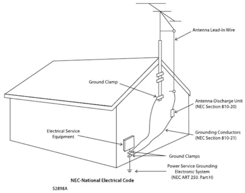
- Lightning – For added protection for this product during a lightning storm, or when it is left unattended and unused for long periods of time, unplug it from the wall outlet and disconnect the antenna or cable systems. This will prevent damage to the product due to lightning and power-line surges.
- Power Lines – An outside antenna system should not be located in the vicinity of overhead power lines or other electric light or power circuits, or where it can fall into such power lines or circuits. When installing an outside antenna system, extreme care should be taken to keep from touching such power lines or circuits as contact with them might be fatal.
-
Overloading – Do not overload wall outlets, extension cords, or integral convenience receptacles as this can result in a risk of fire or electric shock.
-
Object and Liquid Entry – Never push objects of any kind through openings as they may touch dangerous voltage points or short-out parts that could result in a fire or electric shock. Do not expose this product to dripping or splashing and ensure that no objects filled with liquids, such as vases, are placed on the product.
- Servicing – Do not attempt to service this product yourself, as opening or removing covers may expose you to dangerous voltage or other hazards. Refer all servicing to qualified service personnel.
-
Damage Requiring Service – Unplug this product from the wall outlet and refer servicing to qualified personnel under the following conditions:
-
When power-supply cord or plug is damaged.
- If liquid has been spilled, or objects have fallen into the product.
- If the product has been exposed to rain or water.
- If the product does not operate normally by following the operating instructions. Adjust only those controls that are covered by the operating instructions as an improper adjustment of other controls may result in damage and will require extensive work by a qualified technician to restore the product to its normal operation.
- If the product has been dropped or damaged in any way.
-
If the product exhibits a distinct change in performance – this indicates a need for service.
-
Replacement Parts – When replacement parts are required, be sure the technician has used replacement parts specified by the manufacturer or have the same characteristics as the original part. Unauthorized substitutions may result in fire, electric shock, or other hazards.
- Safety Check – Upon completion of any service or repairs to this product, ask the service technician to perform safety checks to determine that the product is in proper operating condition.
- Heat - The product should be situated away from heat sources such as radiators, heat registers, stoves, or other products (including amplifiers) that produce heat.

RECYCLING AND REUSE GUIDELINES (Europe)
In accordance with the European Union WEEE (Waste Electrical and Electronic Equipment) directive effective August 13, 2005, we would like to notify you that this product may contain regulated materials which, upon disposal, require special reuse and recycling processing. For this reason Paradigm Electronics Inc. (the manufacturer of Paradigm speakers and Anthem electronic products) has arranged with its distributors in European Union member nations to collect and recycle this product at no cost to you. To find your local distributor please contact the dealer from whom you purchased this product or go to our website at www.paradigm.com.
Please note that only the product falls under the WEEE directive. When disposing of packaging and other shipping material we encourage you to recycle through the normal channels.
Anthem, Sonic Frontiers, and Paradigm are trademarks or registered trademarks of Paradigm Electronics Inc. Copyright Paradigm Electronics Inc. All rights reserved. The information contained herein may not be reproduced in whole or in part without our express written permission. We reserve the right to change specifications and/or features without notice as design improvements are incorporated.
Thank you for purchasing the Anthem Integrated 225.
The I225 is an integrated preamplifier and amplifier with high undistorted output. Anthem products are engineered to recreate the passion of live performance and thrill of the best movie theaters by using the highest level of circuit design, superior build quality, innovative features, and intuitive ergonomics.
1.1 BEFORE MAKING CONNECTIONS
Check that you have received everything listed below and report discrepancies to your dealer as soon as possible. Retain all packing materials and use them for any future shipment.
Packing List:
- Integrated 225 • CR2025 3V battery • Power cord (North America only)
- Remote control • Operating manual
Keep the invoice that you received from your authorized Anthem dealer at time of purchase – without it, service will not be provided under warranty.
Safety Instructions:
- Read all precautions and instructions at the beginning of this manual.
- Do not connect power if there are signs of damage to any part of the exterior.
- The front panel power button does not disconnect the product from the AC line. Ensure that the power cord remains readily accessible at all times.
- Use only the supplied power cord to connect power.
- Allow adequate ventilation to ensure reliable operation and to prevent overheating. The amount of space required above the unit for radiation depends on ambient air temperature and circulation. Installation inside an unventilated space such as a cabinet with a front that can be closed or a closet is not recommended.
- Failing to comply with any safety instruction, precaution, or warning in this operating manual is in violation of the intended use of the product.
- Anthem and any related party assume no liability for the user's failure to comply with requirements.
1.2 IN-USE NOTICES
- Disconnect the power cord before connecting or disconnecting any components.
- If the product was transported or stored in the cold, let it warm to room temperature before use.
- Do not remove the top cover.
- Do not modify the product.

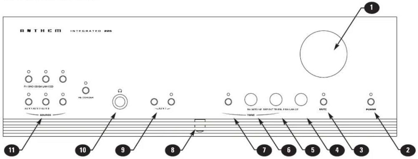
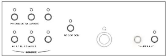
1.3 FRONT AND REAR PANELS
flowchart
graph TD
    A["1"] --> B["Pin 1"]
    C["2"] --> D["Pin 2"]
    E["3"] --> F["Pin 3"]
    G["4"] --> H["Pin 4"]
    I["5"] --> J["Pin 5"]
    K["6"] --> L["Pin 6"]
    M["7"] --> N["Pin 7"]
    O["8"] --> P["Pin 8"]
    Q["9"] --> R["Pin 9"]
    S["10"] --> T["Pin 10"]
    U["11"] --> V["Pin 11"]
    W["Sources"] --> X["Diode CD BLAN CID"]
    Y["REDAVUM"] --> Z["AUX"]
    AA["RASTONE DEFECT TRAIL FLA LAN OF"] --> AB["TONE"]
    AC["MUTC"] --> AD["Power"]
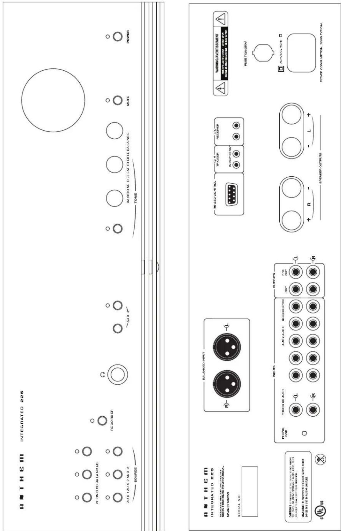
1 - Volume
2 - Power
3 - Mute
4-Balance
5 - Treble
6-Bass
7-Tone Defeat
8 - Infra-red Sensor
9 – Stereo 3.5 mm mini input jack and selector
10 - Headphone jack
11 – Source selection
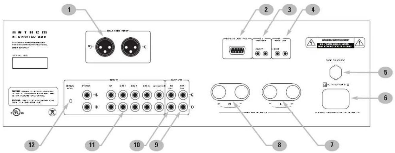
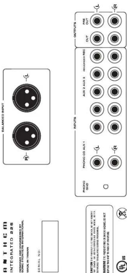
1 - XLR (balanced) input
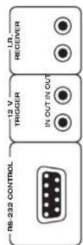
2 - RS-232 interface
3 - 12 Volt trigger in / out
4 - Infra-red receiver in / out
5 - Fuse
6 - Power cord connection
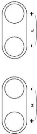
7 - Left speaker output
8 - Right speaker output
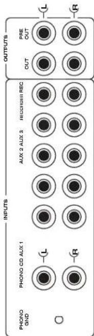
9 - Preamp output
10 - Record output
11 - 5 RCA inputs
12 – Phono input with ground connection
For larger diagrams, see inside back cover.
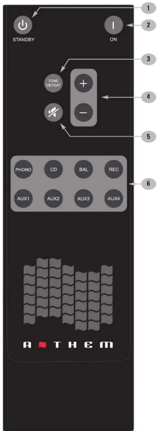
1.5 REMOTE CONTROL
1 - Power off
2 - Power on
3 - Tone enable / bypass
4 - Volume
5 - Mute
6 - Source
Rear: Battery cover
2.1 INPUT CONNECTIONS
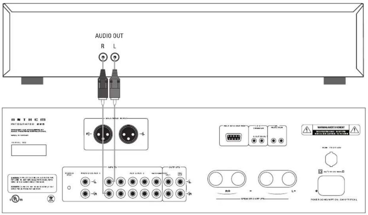
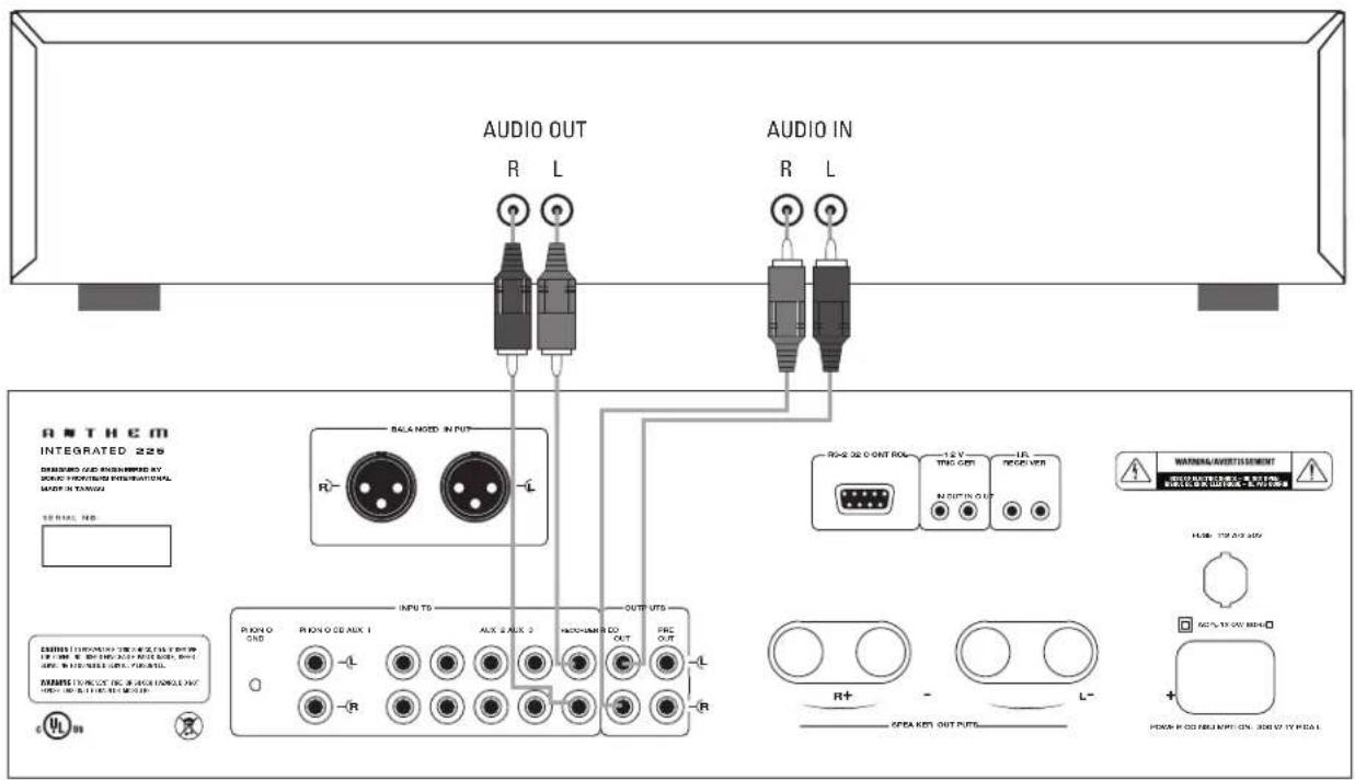
Connect source components and recorder according to the diagrams in the following pages. If using a turntable, connect it to PHONO input only. If the turntable is equipped with a ground wire, connect it to the ground terminal next to the PHONO input by unscrewing the terminal then inserting wire and tightening the screw terminal onto the wire.
Do not use "RCA-compatible" connectors that have a hollow center pin with a hole at the tip. Inserting them into the Integrated 225's RCA jacks can cause internal damage.
2.2 SPEAKER CONNECTIONS
Depending on the level of the input signal, the voltage at the outputs can be high enough to cause electric shock – be sure that power is turned off when connecting or disconnecting anything. As well, be sure that the speakers are rated for use with this amplifier – an overdriven speaker can pose a fire hazard.
Connect the red (+) connection on the speaker to the red (+) binding post on the amplifier, and the black (−) connection on the speaker to the black (−) binding post on the amplifier using cable that is insulated to handle the maximum output of the amplifier. Do not overtighten the binding posts as this may cause damage. The binding post pair accepts a connection from one speaker.
2.3 TRIGGER
This feature allows the amplifier to be turned on or off remotely via the trigger. The 3.5mm (.125") mini-jack INPUT receives a 12V signal from an upstream component or system controller. The same trigger signal can be linked to other components through the OUTPUT.
2.4 INFRA-RED RECEIVER
External IR receivers allow the Remote Control to be used from other locations in your home. Once an IR receiver is wired to another room, connect it to I.R. RECEIVER IN. The signal can be linked to other components through I.R. RECEIVER OUT.
2.5 POWER
After the system is connected use the supplied power cord to connect power. It is normal for a "click" to be heard from inside the chassis when connecting power.

Example 1: CD Player to Integrated 225
Example 2: Recorder to Integrated 225
3.1 POWER ON/OFF
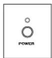
Power on is indicated when the LED above the from panel power button is lit.
Front panel – power ON/OFF
- Press POWER in the lower left of the front panel.
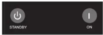
Remote control – power ON
- Press ON in the upper right.
Remote control – power OFF
- Press STANDBY key in the upper left.
3.2 SOURCE SELECTION
Select a source by pressing one of the following buttons:
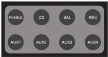
When RECORDER is selected, the REC output is disabled since a recorder cannot record itself.
3.3 VOLUME CONTROL
Front panel:
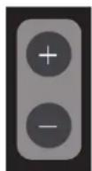
- Rotate the volume knob clockwise to increase the volume and counterclockwise to decrease the volume.
Remote control:
- PRESS the VOL + and VOL+keys.
Mute:
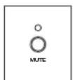
When MUTE is pressed, the audio is silenced and the front panel indicator above the button flashes. Press MUTE again and sound will return.

3. OPERATION continued ...
3.4 BALANCE CONTROL
If the center of the soundstage is off-center, rotate the balance control in the direction that the soundstage needs to be moved. The center position is the default.

3.5 TONE CONTROL
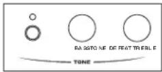
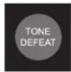
To adjust the bass and/or treble level, rotate the Bass and Treble knobs on the front panel. The center position is the default. If an adjustment is made, you can press TONE on the front panel or remote to quickly turn the adjustment on/off without having to return the knobs to the center position – the indicator above the button lights when the controls are defeated.
It is normal for a "click" to be heard from the chassis when pressing Power, Mute, or a source button.
PHONO PREAMPLIFIER
Input Resistance 47 kΩ
Input Capacitance 100 pF
Maximum Input 18 mV at 20 Hz, 140 mV at 1 kHz, 160 mV at 20 kHz
Gain (at 1 kHz)....35 dB
Crosstalk (at 1 kHz) 80 dB
RIAA Response.... ± 0.5 dB (100 Hz to 20 kHz), -1 dB (20 kHz)
THD+N (at 1 kHz, 5 mV input)....0.05%
S/N Ratio (ref. 5 mV at 1 kHz, IEC-A filter)....83 dB
The phono preamplifier is suitable for moving magnet and high-output moving coil cartridges.
PREAMPLIFIER
Input Resistance 30 kΩ
Output Resistance 560 Ω (Pre Out), 100 Ω (Rec Out)
Rated Input....1.0 Vrms
Maximum Input 7.6 Vrms
Minimum Load 5 kΩ
Rated Output (100 kΩ load) 1.0 Vrms
Maximum Output 7.6 Vrms
Headphone Output....500 mW into 32 Ω at 0.03% THD+N
Crosstalk (at 1 kHz) ....75 dB between channels, 72 dB between inputs
XLR Pin Configuration Pin 1: Ground, Pin 2: Positive, Pin 3: Negative
Frequency Response and Bandwidth ..... 20 Hz to 20 kHz (+0, -0.1 dB), 1 Hz to 170 kHz (+0, -3 dB)
THD+N (at Rated Input & Output) 0.003% (80 kHz BW)
IMD (CCIF at 15 kHz & 16 kHz)....0.0005%
S/N Ratio (ref. 2.0 Vrms, IEC-A filter) 102 dB
POWER AMPLIFIER
Power Output (per channel, continuous RMS, 20 Hz to 20 kHz, <1% THD)
8 Ω....240 W one channel driven, 225 W both channels driven (FTC)
4 Ω....330 W one channel driven, 310 W both channels driven (short term)
Frequency Response 20 Hz to 20 kHz (+0, -0.15 dB)
Bandwidth 1 Hz to 200 kHz (+0, -3 dB)
THD+N 0.01% at 1 kHz, 0.03% at 20 kHz (100 W into 8 Ω)
Power Bandwidth....<10 Hz to 100 kHz (+0, -3 dB, 200 W into 8 Ω)
Slew Rate....25 V/μs
Headroom 1.4 dB (8 Ω), 2.8 dB (4 Ω)
Damping Factor 80 at 1 kHz (ref. 8 Ω)
S/N Ratio (ref. 225 W, IEC-A filter) 105 dB
Crosstalk ....>57 dB (100 Hz to 10 kHz)
Voltage Gain 29 dB
CONTROL
Infra Red
Carrier Frequency....38 kHz
Max. Emitter Current.... pass-through of input
Trigger
Input Polarity ...... non-polarized
Output ...... pass-through of input
POWER REQUIREMENT
Consumption 300 W typical, 800 W maximum (8 Ω load)
Low voltage version: In countries where the line voltage is 120V, this product operates from a single phase AC power source that supplies between 108V and 132V at a frequency of 60 Hz.
High voltage version: In countries where the line voltage is 220, 230, or 240V, this product operates from a single phase AC power source that supplies between 216V and 264V at a frequency of 50 or 60 Hz.
DIMENSIONS
Height 5 ^7/8 in. (14.9 cm) including feet
Width 17 ^1/4 inches (43.8 cm)
Depth 18 inches (45.7 cm)
Weight (unpacked) 42.6 lb (19.4 kg)
CANADA & USA
The warranty period on new Anthem products is:
5 years: Separate power amplifiers and integrated amplifiers
3 years: Audio/Video preamplifiers and receivers
2 years: Projectors, Blu-ray players
6 months: Projector lamps
The warranty period begins on the date of purchase from Anthem or an Authorized Anthem Dealer. If Anthem determines that the product has a defect in materials or manufacturing during the warranty period Anthem will at its option repair, replace or provide the necessary replacement parts without charging for parts or labor. Repaired or replaced equipment or parts supplied under this warranty are covered by the unexpired portion of the warranty.
This warranty is transferable only if the re-sold product is purchased from an Authorized Anthem Dealer. Display products sold by an Authorized Anthem Dealer are covered by the same warranty except that the period commences on the date of the dealer invoice, not the purchaser's invoice, and cosmetic flaws are excluded.
Warranty is void if the serial number has been removed, altered or defaced, if the product has been operated, installed or handled other than in accordance with the intended application, tampered with, modified, or damaged by accident, while in transport or by failure of electric power, or has been repaired by a non-authorized party. Anthem shall have no obligation to correct any defect that is not reproducible by Anthem. If inspection by Anthem discloses that the repair required is not covered by this warranty, regular repair charges shall apply.
If a problem is discovered in your Anthem product, please contact the Authorized Anthem Dealer from whom you purchased the product. Your dealer will help to determine the cause of the problem and arrange for the appropriate action. Alternatively, follow the procedure below for factory service.
A Return Authorization (RA) number must be obtained from Anthem Technical Support before a product can be shipped to Anthem for any reason. Product shipped to Anthem without its RA Number clearly visible on the outside of the shipping carton will be refused and returned to the sender, freight collect. Product shipped to Anthem must have shipping and insurance prepaid by the sender, be packaged in the original carton and packing material and accompanied by a written description of the defect. Service will not be given under warranty without an accompanying copy of the sales invoice. Product repaired under warranty will be returned with shipping and insurance prepaid by Anthem (within Canada and continental USA only).
Disclaimer of Liability
Under no circumstances shall Anthem, its agents, representatives or employees assume liability or responsibility for injury or damages sustained in the use or operation of Anthem products or for damages to connected products. Some jurisdictions do not allow limitations of incidental or consequential damages so this exclusion may not apply to you.
Anthem reserves the right to make design changes without obligation to revise prior versions. All specifications are subject to change without notice.
This warranty shall be the sole and exclusive remedy to you. No other warranty or condition, statutory or otherwise, expressed or implied, shall be imposed upon Anthem nor shall any representation made by any person, including a representative or agent of Anthem, be effective to extend the warranty coverage provided herein.
On the expiration of the warranty all liability of Anthem in connection with the product shall terminate.
INTERNATIONAL
Terms and conditions are set and maintained by the Authorized Anthem Distributor, not Anthem.



A THEM®
THE KEY TO HIGH END AUDIO-VIDEO™
tel. (+1) 905-564-1994 M-F 9:00 am - 5:30 pm (ET)
www.anthemAV.com
- IMPORTANT SAFETY INSTRUCTIONS
- Thank you for purchasing the Anthem Integrated 225.
- BEFORE MAKING CONNECTIONS
- Packing List:
- Safety Instructions:
- IN-USE NOTICES
- REMOTE CONTROL
- INPUT CONNECTIONS
- SPEAKER CONNECTIONS
- TRIGGER
- INFRA-RED RECEIVER
- POWER
- POWER ON/OFF
- SOURCE SELECTION
- VOLUME CONTROL
- Mute:
- OPERATION continued ...
- BALANCE CONTROL
- TONE CONTROL
- PHONO PREAMPLIFIER
- PREAMPLIFIER
- POWER AMPLIFIER
- CONTROL
- Infra Red
- Trigger
- POWER REQUIREMENT
- DIMENSIONS
- CANADA & USA
- Disclaimer of Liability
- INTERNATIONAL
Brand : Anthem
Model : Integrated 225
Category : Receiver