
HDVF-EL20 - Accessoire photo vidéo SONY - Free user manual and instructions
Find the device manual for free HDVF-EL20 SONY in PDF.


| Product Type | OLED Electronic Viewfinder |
| Model | HDVF-EL20 |
| Brand | Sony |
| OLED Panel | 0.7-inch color OLED, 1920 × 1080 effective pixels, 16:9 aspect ratio |
| Brightness | 200 cd/m² (typical) |
| Diopter Adjustment Range | -4.0 to +2.0 m⁻¹ |
| Power Supply | 10.5 V to 17.0 V DC (supplied by camera) |
| Power Consumption | 6.9 W |
| Mass (Approx.) | 770 g (1 lb 11 oz) |
| External Dimensions (W × H × D, Approx.) | 86 × 207 × 150 mm (3.5 × 8.25 × 6 in) |
| Supported Video Formats | 1080 (23.98PsF, 24PsF, 25PsF, 29.97PsF, 50i, 59.94i), 720 (50P, 59.94P) |
| Input Signal | Y: 1.0 Vp-p sync, Pb/Pr: 0.7 Vp-p asynchronous, 75 Ω terminated |
| Operating Temperature | -20°C to +45°C (-4°F to +113°F) |
| Storage Temperature | -20°C to +60°C (-4°F to +140°F) |
| Focus Assist Functions | Color Peaking, Peaking Plus, Magnification (2x) |
| Assignable Switches | 2 (ASSIGN 1 and 2) for user-defined functions |
| Tally Indicators | Front and rear red tally; on-screen green, red, yellow tally indicators |
| Eye Sensor | Controls OLED anti-burn-in; automatically inverts or blanks display when eye is not in contact |
| High Eyepoint Mode | Reduces effective screen size for viewing at a distance |
| Accessories Included | Operation guide, operation manual (CD-ROM), microphone holder |
| Screen Maintenance | Wipe gently with soft dry cloth; avoid alcohol, benzene, thinner, or abrasive cleaners |
| Safety Precautions | Do not leave lens facing strong light; avoid dew condensation; store in level, air-conditioned place |
Frequently Asked Questions - HDVF-EL20 SONY
User questions about HDVF-EL20 SONY
0 question about this device. Answer the ones you know or ask your own.
Ask a new question about this device
Download the instructions for your Accessoire photo vidéo in PDF format for free! Find your manual HDVF-EL20 - SONY and take your electronic device back in hand. On this page are published all the documents necessary for the use of your device. HDVF-EL20 by SONY.
USER MANUAL HDVF-EL20 SONY
Functions of Parts and Controls...... 6
Front panel 7
Indicators on the screen 8
Attaching to the Camera....9
Adjusting Focus and Screen.... 10
Adjusting the Focus ....10
Adjusting the Screen....10
Attaching Accessories.... 11
Attaching the hood (HDVF-EL30 only) ....11
Attaching a Microphone .....12
About the eye sensor.... 12
Switching the eye point 13
Adjusting the LCD monitor (HDVF-EL30 only) 13
Adjusting the angle ....13
Adjusting the screen....13
Using the LCD monitor as the tally......13
Using the Focus Assist Function ..... 14
COLOR PEAKING Function .....14
PEAKING PLUS Function....14
MAGNIFICATION Function .....16
Using the Menu.... 17
Basic Menu Operations....17
List of Menu Items....19
Error Message 23
Specifications.... 23
Precautions
Viewfinder Lenses
Do not leave the viewfinder lens faced toward a strong light source, such as sunlight.
A concentration of strong light, such as sunlight via the lens may burn out the OLED panel or cause a fire.
About the OLED panel
The OLED panel fitted to this unit is manufactured with high precision technology, giving a functioning pixel ratio of at least 99.99%. Thus a very small proportion of pixels may be “stuck”, either always off (black), always on (red, green, or blue), or flashing. In addition, over a long period of use, because of the physical characteristics of the organic light-emitting diode, such “stuck” pixels may appear spontaneously. These problems are not a malfunction.
These phenomena have no effect on the camera's output signals.
Burn-in
Due to the characteristics of the material used in the OLED panel, permanent burn-in or reduction in brightness may occur.
These problems are not a malfunction.
When still images are displayed in the same position on the screen continuously or repeatedly, permanent burn-in may occur.
Images that may cause burn-in
- Character or message displays that indicate settings or the operating state
- On-screen displays such as center markers or safety zones
- Masked images with aspect ratios other than 16:9
• Color bars or images that remain static for a long time - When the HIGH EYEPOINT function is set to "ON."
To reduce the risk of burn-in
- Use with the EYE SENSOR setting set to "ON" This unit has an anti-burn-in function for the OLED panel.
When your eye is away from the eyecup, an image with the video signal level reversed may be displayed or the image may be not displayed.
- Fill the entire screen with images
- Displays the image after switching HIGH EYEPOINT to "OFF."
- Turn the mask display of the connected camera to "OFF" before displaying the image. For details, refer to the operation manual of the camera.
- Turn off the character and marker displays Press the MENU switch to turn off the character displays. To turn off the character or marker displays of the connected equipment, operate the connected equipment accordingly. For details, refer to the operation manual of the connected equipment.
- Turn off the power when not in use Turn off the power if the viewfinder is not to be used for a prolonged period of time.
About the LCD panel (HDVF-EL30 only)
- The LCD panel fitted to this unit is manufactured with high precision technology, giving a functioning pixel ratio of at least 99.99%. Thus a very small proportion of pixels may be “stuck”, either always off (black), always on (red, green, or blue), or flashing. In addition, over a long period of use, because of the physical characteristics of the liquid crystal display, such “stuck” pixels may appear spontaneously. These problems are not a malfunction. These phenomena have no effect on the camera’s output signals.
- Do not leave the screen facing the sun as it can damage the screen. Take care when you use the unit outdoors.
- Do not push or scratch the screen. Do not place a heavy object on the screen. This may cause the screen to lose uniformity.
- An afterimage may appear when a still image is displayed continuously. Turn the viewfinder off when it is not used for a long time.
- When using the viewfinder in low temperature, the moving image resolution deteriorates right after the viewfinder is turned on.
Handling and maintenance of the screen
The surface of the screen is specially coated to reduce image reflection. Make sure to observe the following points as improper maintenance procedures may impair the screen's performance. In addition, the screen is vulnerable to damage. Do not scratch or knock against it using a hard object.
- Be sure to turn off the power of the connected equipment before performing maintenance.
- The surface of the screen is specially coated. Do not attach adhesive objects, such as stickers, on it.
- The surface of the screen is specially coated. Do not touch the screen directly.
- Wipe the screen surface gently with a soft dry cloth to remove dirt.
- Stubborn stains may be removed with a soft cloth slightly dampened with a mild detergent solution.
- The screen may become scratched if a cloth is dusty.
- Never use strong solvents such as alcohol, benzene, thinner, acidic or alkaline detergent, detergent with abrasives, or chemical wipe as these may damage the screen.
- Use a blower to remove dust from the screen surface.
Do not subject the screen to strong impact
Strong impact on the screen may damage it, such as deformation of the internal structure or outer appearance.
Electrolytic capacitor
The life expectancy of the electrolytic capacitor is about 5 years under normal operating temperatures and normal usage (8 hours per day; 25 days per month). If usage exceeds the above normal usage frequency, the life expectancy may be reduced correspondingly.
Operation and storage environment
Store the viewfinder in a level and air-conditioned place. Avoid using or storing in the following places:
- Places that are extremely hot or cold
- Places with a high level of humidity
- Places with strong vibrations
- Places with strong magnetic fields
- Places that are exposed to direct sunlight for long hours or near a heating device
Dew condensation
If the unit is suddenly taken from a cold to a warm location, or if ambient temperature suddenly rises, moisture may form on the outer surface of the unit and/or inside of the unit. This is known as condensation. If condensation occurs, turn off the unit and wait until the condensation clears before operating the unit. Operating the unit while condensation is present may damage the unit.
Disposal of the unit
Do not dispose of the unit with general waste.
Do not include the unit with household waste.
When you dispose of the unit, you must obey the law in the relative area or country.
Overview
The HDVF-EL30/HDVF-EL20 OLED Viewfinder is a color viewfinder for use with a Sony high-definition color camera.
This viewfinder has the following features.
Advantages of OLED panel technology
The OLED panel makes use of an organic material, which emits light when an electric current is applied. Being self-emitting, the strength of luminescence can be controlled by the amount of electric current. This brings about the following three features:
Quick motion picture response:
The luminescent state of the OLED panel can be changed instantaneously by changing the current flow in the organic material. This enables a quick motion picture response and production of images with minimal blurring and ghosting. Furthermore, performance for shooting on location is not influenced by changes in environmental temperature.
High contrast and wide dynamic range:
The OLED panel does not emit light when black signal is applied to the viewfinder, enabling a pure black screen to be displayed. Furthermore, thanks to high peak brightness the panel impressively displays brilliance and clarity of various sparkling images, such as stars in a night sky twinkling, night illuminations winking or glass glittering, etc.
Rich color reproduction:
An OLED panel's self-luminescence also allows for great color reproduction across the entire spectrum in practically any shade or brightness.
Focus Assist function
This viewfinder comes with an original Focus Assist function to support accurate focusing.
- Peaking function
Edge enhancement can be performed in the horizontal/vertical direction on the entire of the screen. Coloring the edge enhancement part can improve visibility. - Peaking Plus function
Edge enhancement can be performed on the object that is specified using a color, area selected, or both.
• Image magnification (FOCUS MAG) function
Displays a part of the image expanded to twice the size.
You can adjust the focus easily.
To switch to preset adjustment settings
Brightness and contrast can be preset for selection through an assignable switch or a menu operation.
Assignable switch
Two assignable switches are provided for the storage of frequently used functions.
Tally lamps
The viewfinder comes with three tally lamps (red, green, and yellow), which light up in response to tally signals.
Check the connected camera to identify whether the use of the yellow tally lamp is supported.
You can use the LCD screen as an up-tally. (HDVF-EL30 only)
High-performance loupe
The 4-group 7-element lens (including aspheric lens) delivers pictures with low distortion and allows adjustment over a wide range of visibility.
If the optional close-up lens ( 37 ) is mounted, you can shift the visibility ratio to the far-sighted side.
Hood for the LCD panel (HDVF-EL30 only)
A small, light hood for the LCD panel is supplied. This is useful when recording.
Functions of Parts and Controls
HDVF-EL30

HDVF-EL20

①Plug
Connect to the VF connector on the camera.
②Stopper
Prevents the viewfinder from coming off the camera when it is slid from side to side.
③Tally indicator (front)
Lights up when the camera receives the red tally signal. The brightness can be adjusted with the TALLY switch on the front panel. Set the TALLY switch to OFF when not in use.
④MENU control
Turn the control to select a menu item, and then press the control to confirm the selection. Use with the MENU switch to set various functions.
When the menu is not displayed, pressing this control shows the status information of the viewfinder on the screen.
For details on operations, see “Using the Menu” on page 17.
⑤Tally indicator (rear)
Lights up when the camera receives the red tally signal. This indicator can be covered when not in use.
⑥Eyecup
Blocks external light while you are shooting.
Over time the eyecup may become cracked. If this occurs, it should be exchanged.
⑦Eye sensor
Controls the anti-burn-in function for the OLED panel.
Notes
- Do not cover or block the eye sensor.
- To prevent screen burn-in on the OLED panel, the video signal level in the display may be inverted or the image may not be displayed when your eye is not in contact with the eyecup.
⑧ Diopter adjustment ring
Turn this until the image is sharpest for your eyesight.
⑨ ASSIGN (assignable) 1/2 switches
Can be used to store frequently used functions. Storing a function is performed using “ASSIGN 1” or “ASSIGN 2” in the FUNCTION menu (page 19).
10MENU switch
Displays the menu. Use with the MENU control to set various functions.
When the menu is not displayed and this switch is pressed and held for three seconds or more, "VR LOCK" appears. This locks the BRIGHT, CONTRAST, and PEAKING controls at their current settings, preventing accidental operation. To unlock the controls, press this switch for three seconds or more again so that "VR UNLOCK" appears.
For details on operations, see "Using the Menu" on page 17.
Front panel

①PEAKING control
Sharpens the edges in the picture. This control has no effect on the camera's video output signals. Turning the control clockwise increases the sharpness.
②CONTRAST control
Adjusts the picture contrast. This control has no effect on the camera's video output signals. Turning the control clockwise increases the contrast.
HDVF-EL20
This control is disabled when “PRESET” in the PRESET menu (page 21) is set to “ON.”
HDVF-EL30
This control is disable when “PRESET” is set to “ON” and “PRESET SELECT” is set to “BOTH” in the PRESET menu (page 21).
③BRIGHT (brightness) control
Adjusts the picture brightness. This control has no effect on the camera's video output signals. Turning the control clockwise increases the brightness.
HDVF-EL20
This control is disabled when “PRESET” in the PRESET menu (page 21) is set to “ON.”
HDVF-EL30
This control is disable when “PRESET” is set to “ON” and “PRESET SELECT” is set to “BOTH” in the PRESET menu (page 21).
④ASPECT/DISPLAY switch
Switches the image display ratio and DISPLAY indication/marker indication ON/OFF.
ASPECT: Each push of the switch to this position toggles the mask display on and off.
DISPLAY: Switches the DISPLAY indication ON/OFF and switches the marker indication ON/OFF when the camera's marker indication is set to "ON."
Note
The motion differs while operating the DISPLAY switch depending on the connecting camera.
⑤ZEBRA (zebra pattern) switch
Controls the zebra pattern display on the viewfinder screen as follows:
ON: A zebra pattern appears and stays.
OFF: The zebra pattern disappears.
MOMENT: A zebra pattern appears and stays for about 5 seconds.
⑥ TALLY switch
Controls the TALLY indicator (page 7) located on the front of the viewfinder.
HIGH: The tally indicator brightness is set to high.
OFF: The tally indicator is disabled.
LOW: The tally indicator brightness is set to low.
Indicators on the screen
Indicators are located on the upper and lower and left and right parts of the OLED and LCD screen (HDVF-EL30 only) to indicate the status of the camera or this unit.

①PEAKING PLUS indicator (blue)
Operates the ASSIGN switch assigned with the PEAKING PLUS function or lights up when “PEAKING MODE” in the PEAKING PLUS menu (page 20) is set to “PLUS.”
②MAG (magnification) position indicator
Shows the expanded display among the center / upper / right / lower / left parts of the screen.
③G TALLY indicator (green)
Lights up when the green tally signal is input.
④R TALLY indicator (red)
Lights up when the red tally signal is input.
⑤Y TALLY indicator (yellow)
Lights up when the yellow tally signal is input.
⑥BATT (battery) indicator (red)
Lights up or flashes, to indicate the status of the battery attached to the camera as follows.
Lit: The battery is drained.
Flashing: The voltage of the battery has dropped below the threshold value.
To prevent camera from shutting down, change the battery as soon as possible after this indicator begins flashing.
The threshold battery voltage value at which this indicator begins lighting up or flashing can be set by the camera. For details, refer to the manual for the camera.
⑦STATUS indicator (amber)
Shows the current status of the viewfinder.
Blinking in intervals of 0.5 seconds: A problem is detected during self-diagnosis. An error message (see page 23) may be displayed at the same time. Turn off the power and contact your Sony service representative.
⑧ (attention) indicator (amber)
Lights up when the camera detects certain conditions. The conditions under which the indicator lights up are specified on the camera.
For details on how to set up and verify the conditions under which the indicator lights up, refer to the manual of the camera in use.
⑨ SAVE indicator (amber)
Lights when the recorder attached to the camera is in power save mode.
⑩MAG (magnification) indicator (amber)
Lights up when the displayed image is magnified (when the ASSIGN switch of the MAGNIFICATION function is set to “ON,” or “MAGNIFICATION” in the MAGNIFICATION menu (page 21) is set to “ON”).
Attaching to the Camera
Note
When the viewfinder is attached, do not leave the camera with the eyepiece facing the sun. Direct sunlight can enter through the eyepiece and be focused in the viewfinder, which may cause the OLED panel to burn out or cause a fire.

1 Loosen the left-right positioning ring on the camera.
2 Insert the slide guide which is located on the front of the camera into the slide rail which is located on the back of the viewfinder.
3 Slide the viewfinder in the direction of the arrow.
4 Position the viewfinder by sliding it from side to side, and tighten the left-right positioning ring on the camera.
5 Connect the plug to the VF connector on the camera.
Note
Always check to be sure that the plug is firmly inserted into the camera's VF connector.
To detach the viewfinder
To detach the viewfinder from the camera, conduct the attachment procedure in reverse. When removing the viewfinder from the camera, pull up the stopper.
Note about loading in carrying case
When loading the camera with viewfinder attached into a carrying case, make sure that the camera and the viewfinder fit into the case without having to be forced. Applying undue pressure can result in damage to the camera or viewfinder.
Adjusting Focus and Screen
Adjusting the Focus
Turn the diopter adjustment ring until the image is sharpest for your eyesight.

To shift the visibility ratio to the far-sighted side
Mount the optional close-up lens ( 37 ) to the thread groove of the loupe.
Adjusting the Screen
For details on the menu operation, see "Using the Menu" on page 17.

1 Set "PRESET" in the PRESET menu (page 21) to "OFF."
2 Turn the BRIGHT control to adjust the brightness of the screen.
To make the picture brighter: Turn the control clockwise.
3 Turn the CONTRAST control to adjust the screen contrast.
To increase the contrast: Turn the control clockwise.
4 Turn the PEAKING control to adjust edges in the image.
To make edges in the image sharper: Turn the control clockwise.
5 Set "CHROMA" in the FUNCTION menu (page 19) to adjust the chroma level.
To adjust the OLED and LCD screen separately (HDVF-EL30 only)
1 Set "PRESET" in the PRESET menu (page 21) to "ON."
2 Set "PRESET SELECT" in the PRESET menu to "OLED" or "LCD."
3 Adjust the brightness of the screen.
If "PRESET SELECT" is not set, turn the BRIGHT control to adjust the picture brightness.
To make the picture brighter: Turn the control clockwise.
If "PRESET SELECT" is set, set "PRST BRIGHT" in the PRESET menu to adjust the picture brightness.
To make the picture brighter: Raise the setting value.
4 Adjust the screen contrast.
If "PRESET SELECT" is not set, turn the CONTRAST control to adjust the screen contrast.
To increase the contrast: Turn the control clockwise.
If "PRESET SELECT" is set, set "PRST
CONTRAST" in the PRESET menu to adjust the screen contrast.
To increase the contrast: Raise the setting value.
5 Turn the PEAKING control to adjust edges in the image.
To make edges in the image sharper: Turn the control clockwise.
6 Set "CHROMA" in the FUNCTION menu (page 19) to adjust the chroma level.
Note
Make sure the setting of "PRESET" in the PRESET menu before performing the procedure above.
Depending on the setting, the BRIGHT and CONTRAST controls may not be operated.
Attaching Accessories
Attaching the hood (HDVF-EL30 only)
1 Attach the hood inserting its claws in the left and right grooves of the LCD monitor.
The hood can also be rotated up and down 180 degrees and attached.

By collapsing the hood while it is attached to the LCD monitor, you can use it as the protection cover of the LCD monitor.
Note
When you retract the LCD monitor with the hood attached, rotate the LCD monitor to the opposite side by 180 degrees so that the hood faces up.
When you retract the LCD monitor forcibly with the hood attached, it may cause a malfunction or damage.

Attaching a Microphone
1 Loosen the screw of the microphone holder and open the holder.

natural_image
Diagram of a mechanical device with a handle and internal components, no visible text or symbols2 Attach the microphone to the microphone holder, then close the holder and tighten the screw.
When necessary to use a slender microphone, attach a microphone spacer (supplied with the microphone) to the microphone beforehand.

natural_image
Diagram of a mechanical device with rotating components and cable (no text or symbols)3 Insert the microphone plug into the MIC connector on the camera, or the MIC IN connector on the camera adaptor.
When connecting the microphone to the camera adaptor, you will need to set the microphone selector.
For details, see the manual supplied with your camera adaptor.
About the eye sensor
Controls the anti-burn-in function of the OLED panel.
For details on the menu operation, see "Using the Menu" on page 17.
1 Set "EYE SENSOR" in the OLED menu to "ON."
Notes
- Use with the EYE SENSOR setting set to "ON." When used with the setting set to "OFF," permanent burn-in may occur.
- Do not cover or block the eye sensor.
- To prevent screen burn-in on the OLED panel, the video signal level in the display may be inverted or the image may not be displayed when your eye is not in contact with the eyecup.
Switching the eye point
When your eye is away from the eyecup while recording, set the HIGH EYEPOINT function to “ON.” The effective screen is displayed with a reduced display and you can see the whole screen easily.

natural_image
Illustration of a sitting dog with floppy ears and open mouth, shown in grayscale (no text or symbols)Normal

natural_image
Illustration of a sitting dog with floppy ears (no text or symbols)When HIGH EYEPOINT is set to "ON"
1 Switch the eye point by pressing the ASSIGN switch assigned with the HIGH EYEPOINT function.
You can set this in "HIGH EYEPOINT" of the OLED menu (page 21).
Notes
- When the HIGH EYEPOINT function is set to “ON,” the resolution of the effective screen decreases.
- When the HIGH EYEPOINT function is set to "ON" and used for extended periods, burn-in may occur.
Adjusting the LCD monitor (HDVF-EL30 only)
When you open the LCD monitor, it turns on. When you retract it with the screen side facing down, it turns off.
Adjusting the angle

You can rotate the LCD monitor to the opposite direction by 180 degrees (the direction in which the monitor faces an object) and to the other direction by 90 degrees.
When you rotate the monitor to the opposite direction by 180 degrees, the image is flipped horizontally (mirror image).
When you retract the monitor with it rotated to the opposite direction by 180 degrees, the image is flipped horizontally and vertically.
The image flip can be set manually by setting "MIRROR" to "MANUAL" in the LCD menu (page 22).
Adjusting the screen
For details on adjusting the screen, see “Adjusting the screen” (page 10).
Using the LCD monitor as the tally
You can use the LCD monitor as the tally.
For details on the menu operation, see "Using the Menu" on page 17.
1 Select "TALLY" in "DISPLAY MODE" in the LCD menu.
2 Set "CAMERA NUMBER" in the LCD menu.
When “CAMERA LINK” is set to “ON” in the LCD menu, the same number as the camera number is set as CAMERA NUMBER.

natural_image
Illustration of a computer monitor with the number 1 displayed on it, no text or symbols presentNote
This function is not compatible depending on the connected camera. For details of compatible models, contact your Sony service representative.
3 Set the brightness in "TALLY DIM" in the LCD menu.
4 By rotating the LCD monitor by 180 degrees to the opposite position, the screen is switched to the tally.
Using the Focus Assist Function
For details on menu operations, see "Using the Menu" on page 17.
COLOR PEAKING Function
When the COLOR PEAKING function is set to "ON," the peaking signal is displayed with the colors changed.
1 Set "COLOR PEAKING" to "ON" in the PEAKING menu.
2 Select the displaying color with "COLOR" in the PEAKING menu.
3 Adjust the chroma level of the video signal with "CHROMA" in the PEAKING menu.
When “ORIG” is selected in “COLOR,” the video signal is displayed in monochrome. The chroma level of the video signal cannot be adjusted.
Note
Color peaking is a function that extracts the high-frequency components of the video signal and applies color to those parts. This may be less effective when noise components are emphasized by VF DETAIL and MASTER GAIN settings on the camera side, because then color is applied to the whole screen. If you plan to use the color peaking function, it is recommended that the VF DETAIL and MASTER GAIN settings on the camera side be set as follows.
- VF DETAIL: OFF, or set to a value that does not emphasize noise.
- MASTER GAIN: Set to a value near 0 dB.
PEAKING PLUS Function
This function can be used to sharpen the edges of an image that is specified using the color, area selected, or both. You can also enhance the edges of the entire image. This function has no effect on the camera's video output signals.
To sharpen edges by specifying the color
1 Press the ASSIGN switch that is assigned the PEAKING PLUS function to switch to the PEAKING PLUS mode.
The PEAKING PLUS indicator lights up.
You can also set to this mode using “PEAKING MODE” from the PEAKING PLUS menu (see page 20).
2 Select "COLOR" under "COLOR/AREA SEL" of the PEAKING PLUS menu.
3 Press and hold the ASSIGN switch that is assigned the PEAKING PLUS function for one second or more (the detection area marker appears in the center of the screen), align the color to be corrected in the detection area marker, and then release the switch.
The color that is to be corrected will be detected.

☐ : Effective edge enhancement area
4 Adjust the effective edge enhancement area of the color using the following menus in the PEAKING PLUS menu.
• HUE PHASE: Hue center position
• HUE WIDTH: Hue range
• SAT WIDTH: Saturation range
– direction:
Narrows the effective range

+ direction:
Widens the effective range
5 Adjust the amount of correction with the PEAKING control.
Only the edges of the object that coincides with the color detected in step 3 will be sharpened.
Turn the control clockwise to make the edges sharper.
To sharpen edges by specifying the display area
1 Press the ASSIGN switch that is assigned the PEAKING PLUS function to switch to the PEAKING PLUS mode.
The PEAKING PLUS indicator lights up.
You can also set to this mode using “PEAKING MODE” from the PEAKING PLUS menu (see page 20).
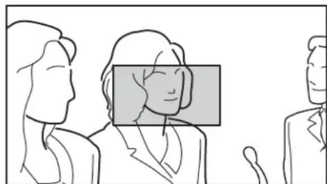
2 Select "AREA" under "COLOR/AREA SEL" of the PEAKING PLUS menu.
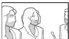
3 Select an area under "POSITION" of the PEAKING PLUS menu.
natural_image
Illustration of three business people in profile, one wearing a headset (no text or symbols)☐ : Effective edge enhancement area
If the “POSITION” setting is changed, the “MAG POSITION” setting in the MAGNIFICATION menu will be changed too.
4 Adjust the amount of correction with the PEAKING control.
Only the edges of the object within the area selected in step 3 will be sharpened.
Turn the control clockwise to make the edges sharper.
To specify both color and area
1 Press the ASSIGN switch that is assigned the PEAKING PLUS function to switch to the PEAKING PLUS mode.
The PEAKING PLUS indicator lights up. You can also set to this mode using “PEAKING MODE” from the PEAKING PLUS menu (see page 20).
2 Select "BOTH" under "COLOR/AREA SEL" of the PEAKING PLUS menu.
3 Select an area under "POSITION" of the PEAKING PLUS menu.
If the “POSITION” setting is changed, the “MAG POSITION” setting in the MAGNIFICATION menu will be changed too.
4 Press and hold the ASSIGN switch that is assigned the PEAKING PLUS function for one second or more (the detection area marker appears in the center of the screen), align the color to be corrected in the detection area marker, and then release the switch.
The color that is to be corrected will be detected.

natural_image
Line drawing of three business people in profile, one highlighted with a magnified inset (no text or symbols)☐ : Effective edge enhancement area
5 Adjust the effective edge enhancement area of the color using the following menus in the PEAKING PLUS menu.
• HUE PHASE: Hue center position
• HUE WIDTH: Hue range
• SAT WIDTH: Saturation range
6 Adjust the amount of correction with the PEAKING control.
The edges of the object that coincides with the color detected in step 4 are sharpened within the area selected in step 3.
Turn the control clockwise to make the edges sharper.
To enhance the edges of the entire image
1 Press the ASSIGN switch that is assigned the PEAKING PLUS function to switch to the STD (standard) mode.
The PEAKING PLUS indicator is turned off. You can also set to this mode using “PEAKING MODE” from the PEAKING PLUS menu (see page 20).
2 Adjust the amount of correction with the PEAKING control.
Turn the control clockwise to make the edges sharper.
MAGNIFICATION Function
This function enables you to adjust the focus easily by enlarging the image vertically and horizontally to two times the size.
For enlarging the image, press the ASSIGN switch assigned with the MAGNIFICATION function. Every press switches between the normal display and enlarged display.
To select the enlarged display part
You can select one of the following as the enlarged display part; center of the monitor (factory setting), upper, right, lower, left.
1 Press and hold the ASSIGN switch assigned with the MAGNIFICATION function for about one second.
The camera enters to the enlarged display part selecting mode, and the MAG indicator and MAG position indicator (page 8) are displayed.
At the same time the screen is switched to the enlarged display.
2 Press and hold the ASSIGN switch assigned with the MAGNIFICATION function. When the MAG position indicator shows your favorite position, release the switch.
The camera switches the enlarged part in the following order;
While pressing and holding the switch the enlarged display is kept. The enlarged display switches among upper, right, lower, left and center about every second.

flowchart
graph LR
    A["Square"] --> B["Square"]
    B --> C["Square"]
    C --> D["Square"]
    D --> E["Square"]
If the “MAG POSITION” setting is changed, the “POSITION” setting in the PEAKING PLUS menu (page 20) also changes.
You can set the enlarged display in the MAGNIFICATION menu (page 21).
To return to normal display
The two manners of returning to the normal display, under "AUTO RELEASE" settings in the MAGNIFICATION menu (page 21), are as follows.
“AUTO”: Returns to the normal display automatically in a specified time after magnifying the image using the ASSIGN switch.
“MANUAL”: Press the ASSIGN switch again to return to the normal display.
Using the Menu
Many of the viewfinder's functions can be set by a menu operation.
Basic Menu Operations
1 Enter the menu.
Press the MENU switch.
A menu page appears in the viewfinder display.
Example

The viewfinder menu can be displayed at the same time a picture from the camera is being displayed. The camera picture or menu darkens so that it appears dimly behind the viewfinder menu.
2 Select a menu page.
While the ? mark appears to the left of the page number (page select mode), turn the MENU control.
The menu changes to another page.

When the desired menu page appears, press the MENU control.
The mark appears to the left of a menu item on the selected menu page (item select mode).
- To select another menu page, press the MENU switch to return to the page select mode.
- If the ? mark appears to the left of the setting (value setting mode), press the MENU switch to change
to item select mode. Press the MENU switch again to change to page select mode.
3 Select menu items.
With the mark positioned to the left of a menu item on the selected menu page (item select mode), turn the MENU control to move the mark to the desired menu item.

To move the mark downward, turn the control clockwise. To move the mark upward, turn the control counterclockwise.
Position the mark to the left of the desired menu item, and then press the MENU control.
A ? mark appears to the left of the setting and the settings screen is activated (value setting mode).
Value setting mode

To select another menu item, press the MENU switch to return to item select mode.
4 Change the value of a setting.
With the ? mark positioned to the left of the setting (value setting mode), turn the MENU control to change the value.
If the setting is a numerical value, turn the MENU control clockwise to increase the value, and counterclockwise to decrease the value.
Turning the control quickly changes the value rapidly, and turning it slowly allows you to make fine adjustments.
5 Enter the setting.
Press the MENU control.
The setting is entered and the menu returns to item select mode.
If you press the MENU switch before pressing the MENU control, the setting returns to the value that was previously set and then the menu returns to item select mode.
6 Set other menu items.
Repeat steps 2 to 5 to set other menu items.
7 End menu operations.
Press the MENU switch repeatedly until the menu page disappears from the display.
To restore a setting to its factory default value
Position the mark to the left of the desired menu item, or while the ? mark appears to the left of the menu item to be restored, press the MENU control for two seconds or more.
List of Menu Items
Notes
- “--” appears as the item that cannot be selected.
- Some settings cannot be selected unless the previous menu item is set to "ON."
| Page | Menu Item Settings | (default in □) | Function | |
| 01 | FUNCTION ASSIGN 1 | MONO/MAG/ | PEAK+/HIEYE/KNEE/PRESET/OFF | For assigning a function to the ASSIGN 1 switch.Detailed settings of the individual features can be specified on the respective menu pages.MONO: Toggles the black-and-white display between ON and OFF.MAG: Toggles the magnification function between ON and OFF (Press and hold for one second or more to select the area to magnify).PEAK+: Toggles the peaking mode between STD and PLUS (Press and hold for one second or more to execute COLOR DETECT).HIEYE: Switches the reduced display function ON/OFF.KNEE: Toggles the KNEE correction circuit between ON and OFF.PRESET: Toggles PRESET between ON and OFF.OFF: No function assigned. |
| ASSIGN 2 MONO/ | MAG/PEAK+/HIEYE/KNEE/PRESET/OFF | For assigning a function to the ASSIGN 2 switch.The assignable functions are the same as those for ASSIGN 1. | ||
| KNEE | OFF/ON | For turning the KNEE correction circuit ON or OFF. (This setting does not affect the camera's output signals.) | ||
| MONOCHROME | OFF/ON | For selecting color display (OFF) or black-and-white display (ON). (This setting does not affect the camera's output signals.) | ||
| CHROMA | -99 to 0 to 99 | For setting the chroma level. (This setting does not affect the camera's output signals.)Lowering the value decreases the chroma level. | ||
| PEAKING PLUS SW | MODE1/MODE2 | For selecting the operation mode upon pressing the ASSIGN switch that is assigned the PEAKING PLUS function.MODE1: Toggles PEAKING MODE STD ⇌ PLUS.MODE2: Toggles in the sequence of STD → COLOR → AREA → BOTH → STD. | ||
| 02 | TALLY/IND | TALLY | OFF/ON/UPPER/LOWER | Controls the tally indicator in the screen.OFF: All tally indicators are invalid.ON: All tally indicators are valid.UPPER: Only the upper tally indicator is valid.Lower: Only the lower tally indicator is valid. |
| INDICATOR | OFF/ON | Controls the indicators (except for tally indicator) in the screen.OFF: Only the BATT and STATUS indicators are valid.ON: All indicators are valid. | ||
| TALLY/IND DIM OLED | 1 to 5 to 10 | Set the amount of light of the indicators (including the tally indicator) displayed in the OLED.The bigger the number, the brighter the indicator. The smaller the number, the dimmer the indicator. | ||
| TALLY/IND DIM LCD(Only HDVF-EL30 is valid.) | 1 to 5 to 10 | Set the amount of light of the indicators (including the tally indicator) displayed in the LCD panel.The bigger the number, the brighter the indicator. The smaller the number, the dimmer the indicator. | ||
| Page | Menu | Item | Settings (default in □) | Function |
| 03 | PEAKING | FREQUENCY | L/M/MH/H | Set the center frequency of edge enhancement signals. |
| RANGE | 1/2/3/4 | Set the variable range of the level of edge enhancement signals. | ||
| COLOR PEAKING | OFF/ON The edge | enhancement signals are displayed converted to the color.OFF: Enhance the edge in white.ON: Enhance the edge in the color specified in “COLOR.” | ||
| COLOR BLUE/RED/YELLOW/GREEN/ORIG | When “ON” is set in “COLOR PEAKING,” select the color of the edge enhance signals.BLUE: Enhance the edge in blue.RED: Enhance the edge in red.YELLOW: Enhance the edge in yellow.GREEN: Enhance the edge in green.ORIG: Displays in monochrome and enhances the edge in the original color. | |||
| CHROMA | -99 to 0 to 99 | Set the chroma level. (This does not affect to the camera’s outputting level.)The smaller the number, the less the amount of chroma.The setting is linked to the “CHROMA” setting of the FUNCTION menu. | ||
| 04 | PEAKING PLUS | PEAKING MODE | STD/PLUS | For selecting a peaking mode.STD: Standard modePLUS: PEAKING PLUS mode |
| COLOR/AREA SEL | COLOR/AREA/BOTH | For selecting a PEAKING PLUS mode.COLOR: Sharpens the edges for the selected color only.AREA: Sharpens the edges for the selected area only.BOTH: Sharpens the edges for the selected color and area only. | ||
| POSITION | CENTER/UPPER/RIGHT/LOWER/LEFT | For selecting the effective PEAKING area when “AREA” or “BOTH” is selected in “COLOR/AREA SEL.”The setting is linked to the “MAG POSITION” setting of the MAGNIFICATION menu.CENTER: Sharpens the edges of the center area.UPPER: Sharpens the edges of the upper area.RIGHT: Sharpens the edges of the right area.LOWER: Sharpens the edges of the lower area.LEFT: Sharpens the edges of the left area. | ||
| COLOR DETECT | EXEC For detecting | the color of which its edges are to be enhanced.This feature is enabled only when “COLOR” or “BOTH” is selected in “COLOR/AREA SEL.” | ||
| HUE PHASE | 0 to 359 | For specifying the hue center position of which edge enhancement is to be performed. | ||
| HUE WIDTH | 1 to 45 to 360 | For specifying the hue range of which edge enhancement is to be performed. | ||
| SAT WIDTH | -99 to 0 to 99 | For specifying the saturation range of which edge enhancement is to be performed. | ||
| 05 | MAGNIFICATION | MAGNIFICATION | OFF/ON | For selecting normal display (OFF) or magnified display (ON). Normal display (OFF) is selected whenever the power is turned on. |
| MAG POSITION | CENTER/ UPPER/RIGHT/ LOWER/LEFT | For selecting the area to magnify when the magnification mode is enabled. The “MAG POSITION” setting is linked to the “POSITION” setting of the PEAKING PLUS menu.CENTER: Magnifies the center area.UPPER: Magnifies the upper area.RIGHT: Magnifies the right area.Lower: Magnifies the lower area.LEFT: Magnifies the left area. | ||
| AUTO RELEASE | AUTO/MANUAL | For specifying the manner in which the magnified display returns to normal display.AUTO: After the magnified display appears by pressing ASSIGN switch, the display returns to normal automatically after the specified time.MANUAL: After the magnified display appears by pressing ASSIGN switch, the display returns to normal when ASSIGN switch is pressed again. | ||
| 06 | PRESET | PRESET | OFF/ON | For selecting whether to enable the settings of BRIGHT, CONTRAST controls and enables the preset “PRST BRIGHT” and “PRST CONTRAST” values in the PRESET menu.OFF: Enables the preset level that is set by the controls ON: Enables the PRESET menu settings |
| PRESET SELECT(Only HDVF-EL30 is valid.) | BOTH/OLED/LCD | When “ON” is selected in “PRESET,” select the panel in which each PRESET value is reflected.BOTH: Reflects the PRESET value to both the OLED and LCD panel.OLED: Reflects the PRESET value only to the OLED panel.LCD: Reflects the PRESET value only to the LCD panel. | ||
| PRST BRIGHT | -99 to 0 to 99 | For setting the image brightness when “ON” is selected in “PRESET.”Raising the value increases the brightness of the image. | ||
| PRST CONTRAST | -99 to 0 to 99 | For setting the image contrast when “ON” is selected in “PRESET.”Raising the value increases the contrast of the image. | ||
| 07 | STATUS DISPLAY | ASSIGN 1 | OFF/ON | For selecting whether the changes in the status of the function assigned to the ASSIGN 1 switch is displayed (ON) or not (OFF). |
| ASSIGN 2 | OFF/ON | For selecting whether the changes in the status of the function assigned to the ASSIGN 2 switch is displayed (ON) or not (OFF). | ||
| BRIGHT | OFF/ON | For selecting whether the setting of the BRIGHT control is displayed (ON) or not (OFF). | ||
| CONTRAST | OFF/ON | For selecting whether the setting of the CONTRAST control is displayed (ON) or not (OFF). | ||
| PEAKING | OFF/ON | For selecting whether the setting of the PEAKING control is displayed (ON) or not (OFF). | ||
| 08 | OLED | HIGH EYEPOINT | OFF/ON | Switches between the normal display (OFF) and HIGH EYEPOINT (ON). |
| EYE SENSOR | OFF/ON Set the eye sensor to ON or OFF. Set to “ON” normally.When set to “OFF,” anti-burn-in to the OLED panel is not processed and burn-in may occur. | |||
| 09 LCD(Only HDVF-EL30 is valid.) | DISPLAY MODE | MAIN/TALLY | Switches the mode of the LCD panel.MAIN: Camera display.TALLY: TALLY display. | |
| CAMERA NUMBER | OFF/1 to 99 When “TALLY” is selected in “DISPLAY MODE,” set the camera number.When “CAMERA LINK” is set to “ON,” the number is set automatically. | |||
| CAMERA LINKa) | OFF/ON Switches the status of acquiring the camera number from the camera automatically (ON) or manually (OFF). | |||
| TALLY DIM | 1 to 5 to 10 | When “TALLY” is selected in “DISPLAY MODE,” set the displayed tally indicator’s amount of light.The bigger the number, the brighter the indicator. The smaller the number, the dimmer the indicator. | ||
| MIRROR | AUTO/MANUAL | Set the reverse method of the LCD screen vertically and horizontally.AUTO: Automatically reverses vertically or horizontally, depending on the LCD panel position.MANUAL: Manually set the reverse of the LCD screen vertically or horizontally. | ||
| L/R | OFF/ON | When “MANUAL” is selected in “MIRROR,” switches between the normal display (OFF) and the image reverse display horizontally (ON). | ||
| B/T | OFF/ON | When “MANUAL” is selected in “MIRROR,” switches between the normal display (OFF) and the image reverse display vertically (ON). | ||
a) When a compatible camera is connected, this function is valid.
Error Message Specifications
| Display Description | |
| ERROR Failure in “COLOR DETECT” in PEAKING PLUS mode | |
| BACKUP ERROR C | checksums of the EEPROM backup data are not consistent |
| DEVICE ERROR O | ther device errors |
General
Power supply 10.5 V to 17.0 V DC (supplied by the camera)
Power consumption HDVF-EL30: 7.3 W HDVF-EL20: 6.9 W
Operating temperature -20°C to +45°C (-4°F to +113°F)
Storage temperature -20°C to +60°C (-4°F to +140°F)
Mass HDVF-EL30: 920 g (2 lb 0.46 oz) (not including hood) HDVF-EL20: 770 g (1 lb 11 oz)
External dimensions See “External dimensions” on page 24.
OLED panel
0.7-type color OLED panel Display area 15.8 × 9.0 mm ( ^5/8 × ^3/8 inches) (H/V, 16:9 aspect ratio) Diopter range for the loupe -4.0 to +2.0 m ^-1
Performance
Brightness 200 cd/m ^2 (typical) Effective pixels 1920 (horizontal) × 1080 (vertical) × 3 (RGB) Color temperature D65
LCD panel (HDVF-EL30 only)
3.5-type color TFT transmissive LCD panel Effective screen size 77.0 × 43.3 mm (3 ^1/8 × 1 ^3/4 inches) (H/V, 16:9 aspect ratio)
Performance
Brightness 300 cd/m ^2 (typical) Effective pixels 960 (horizontal) × 540 (vertical) × 3 (RGB) Color temperature D65
Input signals
Y 1.0 Vp-p, synchronous, 75 ohm terminated Pb, Pr 0.7 Vp-p, asynchronous, 75 ohm terminated
Supported formats
| Effective scanning lines | Format Horizontal scanning frequency (kHz) | Vertical scanning frequency (Hz) | |
| 1080 23.98Ps | F 26.97 47.95 | ||
| 24PsF 27.00 48 | |||
| 25PsF 28.13 50 | |||
| 29.97PsF 33.72 59.94 | |||
| 50i 28.13 50 | |||
| 59.94i 33.72 59.94 | |||
| 720 50P 36.00 | 50 | ||
| 59.94P 44.96 | 59.94 | ||
Connectors
Camera connector
Round type 20-pin
Accessories
Operation guide (1)
Operation manual (CD-ROM) (1)
Hood (1) (HDVF-EL30 only)
Related products
HD Color Camera
HDC4300
HDC2500 series
HSC300R/HSC100R series
Disc Camcorder PDW-680/700/750/850/F800
Solid-State Memory Camcorder
PMW-500/PXW-X500
Digital Motion Picture Camera
F65
Designs and specifications are subject to change without notice.
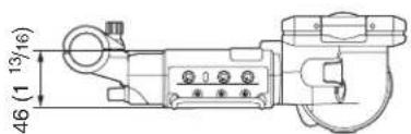
External dimensions
HDVF-EL30
Unit: mm (inches)


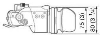
HDVF-EL20
Unit: mm (inches)


Notes
• Always verify that the unit is operating properly before use. SONY WILL NOT BE LIABLE FOR DAMAGES OF ANY KIND INCLUDING, BUT NOT LIMITED TO, COMPENSATION OR REIMBURSEMENT ON ACCOUNT OF THE LOSS OF PRESENT OR PROSPECTIVE PROFITS DUE TO FAILURE OF THIS UNIT, EITHER DURING THE WARRANTY PERIOD OR AFTER EXPIRATION OF THE WARRANTY, OR FOR ANY OTHER REASON WHATSOEVER.
- SONY WILL NOT BE LIABLE FOR CLAIMS OF ANY KIND MADE BY USERS OF THIS UNIT OR MADE BY THIRD PARTIES.
- SONY WILL NOT BE LIABLE FOR THE TERMINATION OR DISCONTINUATION OF ANY SERVICES RELATED TO THIS UNIT THAT MAY RESULT DUE TO CIRCUMSTANCES OF ANY KIND.
The material contained in this manual consists of information that is the property of Sony Corporation and is intended solely for use by the purchasers of the equipment described in this manual.
Sony Corporation expressly prohibits the duplication of any portion of this manual or the use thereof for any purpose other than the operation or maintenance of the equipment described in this manual without the express written permission of Sony Corporation.
HDVF-EL30 (SY)
HDVF-EL20 (SY)
4-584-439-11(1)
- Precautions
- Viewfinder Lenses
- About the OLED panel
- Burn-in
- To reduce the risk of burn-in
- About the LCD panel (HDVF-EL30 only)
- Handling and maintenance of the screen
- Do not subject the screen to strong impact
- Electrolytic capacitor
- Operation and storage environment
- Dew condensation
- Disposal of the unit
- Overview
- Advantages of OLED panel technology
- Quick motion picture response:
- High contrast and wide dynamic range:
- Rich color reproduction:
- Focus Assist function
- To switch to preset adjustment settings
- Assignable switch
- Tally lamps
- High-performance loupe
- Hood for the LCD panel (HDVF-EL30 only)
- Functions of Parts and Controls
- ①Plug
- ②Stopper
- ③Tally indicator (front)
- ④MENU control
- ⑤Tally indicator (rear)
- ⑥Eyecup
- ⑦Eye sensor
- Notes
- ⑧ Diopter adjustment ring
- ⑨ ASSIGN (assignable) 1/2 switches
- 10MENU switch
- ①PEAKING control
- ②CONTRAST control
- HDVF-EL20
- HDVF-EL30
- ③BRIGHT (brightness) control
- ④ASPECT/DISPLAY switch
- Note
- ⑤ZEBRA (zebra pattern) switch
- ⑥ TALLY switch
- Indicators on the screen
- ①PEAKING PLUS indicator (blue)
- ②MAG (magnification) position indicator
- ③G TALLY indicator (green)
- ④R TALLY indicator (red)
- ⑤Y TALLY indicator (yellow)
- ⑥BATT (battery) indicator (red)
- ⑦STATUS indicator (amber)
- ⑧ (attention) indicator (amber)
- ⑨ SAVE indicator (amber)
- ⑩MAG (magnification) indicator (amber)
- Attaching to the Camera
- To detach the viewfinder
- Note about loading in carrying case
- Adjusting Focus and Screen
- Adjusting the Focus
- To shift the visibility ratio to the far-sighted side
- Adjusting the Screen
- To adjust the OLED and LCD screen separately (HDVF-EL30 only)
- Attaching Accessories
- Attaching the hood (HDVF-EL30 only)
- Attaching a Microphone
- About the eye sensor
- Switching the eye point
- Adjusting the LCD monitor (HDVF-EL30 only)
- Using the LCD monitor as the tally
- Using the Focus Assist Function
- COLOR PEAKING Function
- PEAKING PLUS Function
- To sharpen edges by specifying the color
- To sharpen edges by specifying the display area
- To specify both color and area
- To enhance the edges of the entire image
- MAGNIFICATION Function
- To select the enlarged display part
- To return to normal display
- Using the Menu
- Basic Menu Operations
- Enter the menu.
- Example
- Select a menu page.
- Select menu items.
- Value setting mode
- Change the value of a setting.
- Enter the setting.
- To restore a setting to its factory default value
- List of Menu Items
- Error Message Specifications
- General
- OLED panel
- Performance
- LCD panel (HDVF-EL30 only)
- Input signals
- Connectors
- Accessories
- Related products
- External dimensions
Brand : SONY
Model : HDVF-EL20
Category : Accessoire photo vidéo