
UwMic9 - Receiver Saramonic - Free user manual and instructions
Find the device manual for free UwMic9 Saramonic in PDF.


| Product Type | UHF Wireless Receiver |
| Model | UwMic9-RX9 |
| Brand | Saramonic |
| Number of Channels | 96 (2 groups: A and B) |
| Frequency Range | 514-596 MHz |
| Oscillator Type | PLL Synthesizer |
| Audio Output Connector | 3.5 mm mini jack (locking) |
| Antenna | 1/4 λ wire antenna (2) |
| Headphone Output | 3.5 mm stereo jack, 30 mW (16 Ω) |
| Audio Output Level | -60 dBV |
| Receive Sensitivity | -95 dBm |
| Signal-to-Noise Ratio | ≥70 dB |
| Frequency Response | 40 Hz - 18 kHz (±3 dB) |
| Distortion | ≤0.5% |
| Spurious Suppression | -60 dB |
| Voice Delay | 12 ms |
| Power Supply | 2x AA batteries (not included) |
| Weight (without batteries) | Approx. 218.7 g |
| Dimensions | 170.9 × 63.5 × 30.0 mm |
| Operating Temperature | 0°C to 50°C |
| Storage Temperature | -20°C to +55°C |
| Included Accessories | Shoe mount adapter, belt clip, XLR to 3.5mm locking cable, 3.5mm audio cable |
Frequently Asked Questions - UwMic9 Saramonic
User questions about UwMic9 Saramonic
0 question about this device. Answer the ones you know or ask your own.
Ask a new question about this device
Download the instructions for your Receiver in PDF format for free! Find your manual UwMic9 - Saramonic and take your electronic device back in hand. On this page are published all the documents necessary for the use of your device. UwMic9 by Saramonic.
USER MANUAL UwMic9 Saramonic
Please read this manual carefully before using and strictly operate and store in accordance with the instructions. Please save it for your future reference.
If the user manual can not help you to solve certain problems, please ask your retailer for help or email us: info@saramonic.com.
Cautions
- Do not use the unit under water, don't expose it to rain. Please store it in a cool, dry place.
- Please use and store it in normal temperature. Do ot move it from overheated to supercooled condition frequently as well as keep away from heat sources such as heater and oven.
- When using and storing, please pay attention to dust and moisture.
- Be careful to violent collision.
- To avoid acoustical feed-back, do not hold the microphone close to the loudspeakers.
- For the best sound pick-up pattern do not hold your hand against the microphone head.
- Remove the batteries from the battery compartment when the device is not used for a long time.
Contents
General Introduction....2
Portable Receiver UwMic9-RX9 2
Introduction....2
Product Structure 2
Attaching Accessories....4
LCD Display Operation Guide 5
Body-pack Transmitter UwMic9-TX9....9
Introduction....9
Product Structure 9
Attaching Accessories....10
LCD Display Operation Guide 11
Hand-held Microphone UwMic9-HU9 14
Introduction....14
Product Structure 14
Setup Guide 15
Plug-on Transmitter UwMic9-TX-XLR9....16
Introduction....16
Product Structure 16
Attaching Accessories....17
LCD Display Operation Guide 18
Plug-on Receiver UwMic9 RX-XLR9 21
Introduction....21
Product Structure 21
Attaching Accessories....23
LCD Display Operation Guide 23
UwMic9 SP-RX9 26
Product Structure 26
Introduction....26
LCD Display Operation Guide 28
Operation Guide 32
Specification.... 37
Receiver RX9 and RX-XLR9 37
Transmitter TX9, HU9 and TX-XLR9 38
Receiver SP-RX9 38
Packing list....40
General Introduction
The Saramonic UwMic9 UHF wireless microphone system is intended for portable wireless operation and can be used in several environments for applications such as DSLR video, field recording, broadcast TV, electronic news gathering (ENG), on-the-spot interviews, and more.
Portable Receiver UwMic9-RX9
Introduction
The Saramonic UwMic9-RX9 is a camera-mountable integrated wireless receiver. It features a wide switching RF bandwidth, an easy-to-read LCD display and infrared synchronization between transmitter and receiver.
Equipped with an auto-scan function, the RX9 can automatically search for an available transmission frequency.
The selectable output mode allows you to choose the output signal to be mono or stereo.
Product Structure

① Antennas
② Power button
Long Press to turn on or off the RX9.
③ SET button
Long press the SET button to enter the displayed menu. Then, short press the SET button to confirm your option or long press again to exit without saving.
④ POWER indicator
Indicates the battery level as follows:
Green light: Sufficient battery level.
Red light: Low battery level.
⑤ RF indicator and infrared transmitter port
The infrared transmitter port sends the set frequency to a transmitter.
RF indicator displays the RF input level as follows:
Green light: RF signal is strong.
Red light: RF signal is weak or disconnected.
⑥ + or - button
Selects functions or values shown on the display.
⑦ LCD display
Display menus, please refer to "LCD Display Operation Guide" (page 5) for more details.
⑧ Battery compartment
Operates on two AA batteries (not included).
⑨ Phone jack
It is a 3.5mm diameter and stereo mini headphone jack.
Connect a headphone to monitor the audio output
Note: Please do not connect a headphone with a monaural mini jack. As this may short-circuit the headphone jack and distorted sound output.
⑩ Output jack
Connect the RX9 to a video camera, camcorder, mixer or amplifier with the supplied output cable.
⑪ Standard cold shoe
Attaching Accessories
Connect the supplied cable to the output jack.

① Plug the supplied cable into the OUTPUT jack.
② For a secure connection, turn to lock the connector.
Attach a belt clip. Please Refer to "Attaching Accessories" (page 11).
Attach the shoe mount adapter.
① Please attach the belt clip upside-down before attaching the shoe mount adapter.
② Push the bottom of the belt clip to make some space between the belt clip and the receiver.
③ Align the belt clip with the two vertical grooves on the shoe mount adapter and insert the adapter in the direction of the arrow.
④ Push the shoe mount adapter in fully until the belt clip fits into the horizontal groove on the adapter holds.

LCD Display Operation Guide
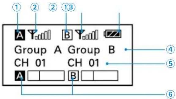
Home screen. If no operation is performed for 20 seconds on the other screens, the display will automatically return to the home screen.
① Group icon
A Indicates the power of group A is turned off.
A Indicates the power of group A is turned on.
② RF level indicator Indicates the current reception level.
③ Battery level indicator Displays the battery level. Please replace both batteries immediately when the indicator starts flashing.
④ Name of the channel group
⑤ Current channel Displays the current channel number.
⑥ Audio input level meter Displays the audio input level.

Power key. Long press the SET button to unlocked or locked the power key. Lock the power key to prevent the receiver being turned off unwittingly while using.
- Unlocked: Long press the power key to turn the receiver on or off (System default).
- Locked: The receiver will not be turned off even after pressing the power key.
Note: If the batteries are removed and reinserted while the power key is set to Locked, the lock state of the Power key will not be changed. You can turn on the receiver by long pressing the power button.

Output mode. The output mode can be selected to mono or stereo. When the output mode is mono, the audio from left and right channel will be mixed. When it is stereo, the left (Group B) and right (Group A) audio channel output will be separated. System default is mono.
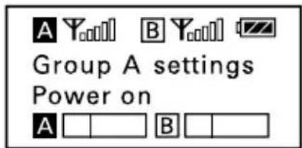

Power of the Group. When you only use one group signal, please turn off the other group to save battery. To save battery, system default of the Group B is power off while the Group A is power on.
When operating two transmitters simultaneously, please set each transmitter to a different group to prevent interference or noise.


Select channel. Details of operation, please refer to "Manually setting the receiver channel" (page 35).


Set output volume. Set the volume of output audio within the range 0 to 30. The setting is retained even after the power is turned off. Default is 27.

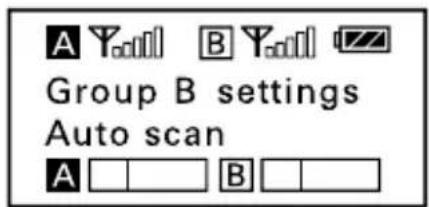
Auto scan function. Automatically scan an available and clear channel. Details of operation, please refer to "Using the auto scan function" (page 34).

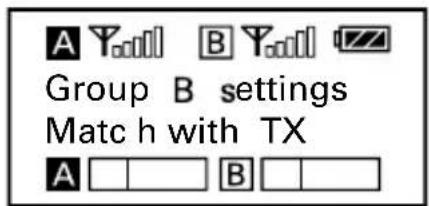
Infrared matching function. Match the receiver and transmitter via infrared. Details of operation, please refer to "Match the channel of receiver and transmitter" (page 35).

Set backlight. Set the background LED light to ON or Delay 60/30/10 seconds or OFF. Default is "Delay 10s."

This transmitter is a compact transmitter that employs a crystal-controlled PLL synthesizer. It is equipped with a muting function and a locking-type microphone input connector. The RF power output can be switched among high, middle and low.
Product Structure
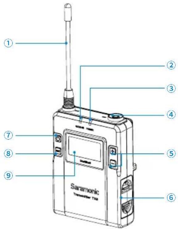
① Antenna
② AUDIO indicator / IR (infrared detector)
AUDIO indicator: Indicates the audio input level.
IR (infrared detector): Receives the frequency from the receiver.
Solid Green: Audio input level is appropriate.
Flashing Red: Audio is muted (i.e., disabled).
For details on setting the mute function, please refer to
"Set Mute key" (page 13).
③ POWER indicator
Indicates the battery level as follows:
Solid Green: Sufficient battery level.
Solid Red: Low battery.
④ Audio input connector (3.5mm locking-type plug)
Connect to the supplied lavalier microphone.
⑤ + or - button
Selects functions or values shown on the display.
⑥ Battery compartment
Accepts two AA batteries (alkaline, nickel metal hydride, or lithium batteries).
⑦ Power / Mute button
| Function Operation | |
| Power ON Press button | for one second or longer |
| Power OFF Press button | until it turns off |
| Mute ON | Short press button |
| Mute OFF |
⑧ SET button
Long press the SET button to enter the displayed menu. Then, short press the SET button to confirm your option or long press again to exit without saving.
⑨ LCD display
Display menus, please refer to "LCD Display Operation Guide" (page 11) for more details.
Attaching Accessories
natural_image
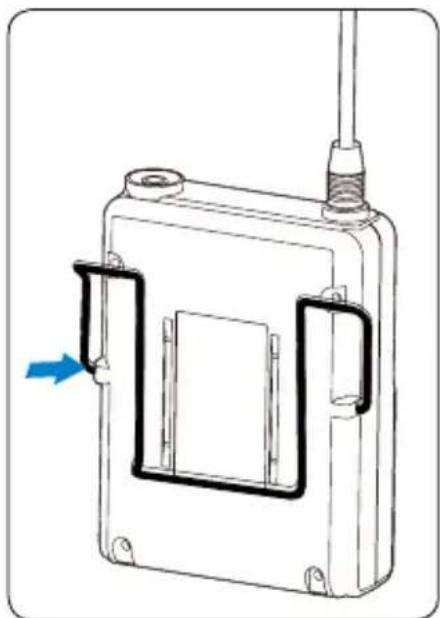
Technical line drawing of a mechanical device with no visible text or symbols1. Attach a belt clip
Insert one end of the belt clip into one of two holes on either side of the transmitter, and then insert the other end into the hole on the other side.

2. Connect the microphone
For a secure connection, turn to lock the connector.
Note: Please turn off the transmitter before attaching or removing the microphone.
LCD Display Operation Guide
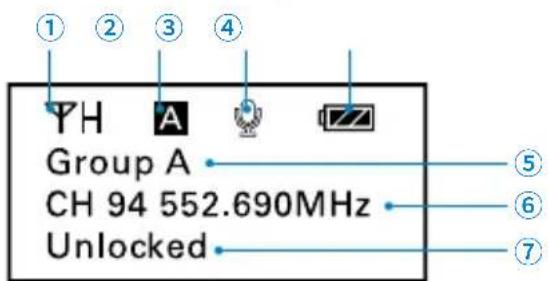
Home screen. If no operation is performed for 20 seconds on the other screens, the display will automatically return to the home screen.
① RF transmission power indicator Indicates the current transmission power level. For details on setting the level, please see "Select RF power level" (page 12).
② Channel group indicator Indicates the channel group.
③ Mute indicator Mute OFF Mute ON
④ Battery level indicator Displays the battery level. Please replace both batteries immediately when the indicator starts flashing.
⑤ Name of the channel group
⑥ Channel and frequency
Indicate the current channel and frequency.
⑦ The status of Power / Mute button.

① Menu display section. Displays various functions. Press the + or - button to switch functions.
Set Power key. Select Unlocked or Locked.
Set "Locked" to lock the power button to prevent the unit being turned off or muted unwittingly while using. Default is "Unlocked."

Select Channel. Long press the SET button to enter the menu. Use the "+" and "-" to select the channel you need and shot press the SET button to confirm.

Select Group. You can choose "A" or "B" channel group. Each group has 96 channels. Default is 'Group A.'

Select RF power level. You can set the transmitted RF power to High, Middle or Low. Default is "High."

Set Mute key. If you want to mute the audio, please select "Enable" first and then short press the power button. Default is "Enable."

IR Match. Set to match with the receiver. The screen will display "Matching" when in process. After successful matching, it will indicate "Sync finished."

Set Backlight. Select ON, OFF or Delay 10 / 30 /60 seconds. Default is "Delay 10s."

Version of the UwMic9-TX9.

Serial Number.
Hand-held Microphone UwMic9-HU9
Introduction
Saramonic HU9 is a handheld wireless UHF microphone transmitter features a compact metallic body, an easy-to-read LCD display, a RF power switch and a PLL synthesizer. The broadcast quality microphone will capture crystal clear and rich sound. It has a built-in antenna, a muting function and power lock function. The channel of HU9 is synced up with the receiver via infrared.
Product Structure

① LCD screen
A. Channel Groups.
Two channel groups: A and B. Each group has 96 channels.
B. Channel number.
C. Battery level indicator.
D. MUTE. Audio is muted.
This LCD display indicates it is operating on channel 96 of group A.
② Power / Mute button
Power: Long press to turn on/off the HU9.
Mute: Short press the button while transmitting, the audio will be muted. Press it again to restore the audio output.
Note: In muting, the audio signal is not output but an RF signal is still transmitted.
③ Antenna
④ Operation panel

A. Infrared detector. Receives the frequency set on the receiver.
B. Lock switch. Set to ON will lock the power button. It will prevent the power being turned off inadvertently during transmission.
Note: The lock switch will not lock the mute function.
C. RF power. Set the transmit output level to HIGH or LOW.
⑤ Battery compartment
Operates on two AA batteries (not included).
You could use alkaline, lithium or nickel metal hydride batteries.
Setup Guide
- Install the batteries. Refer to "UwMic9-HU9" (page 33).
- (Option) Set the lock switch to ON or OFF.
- (Option) Set the RF power to HIGH or LOW. The transmit power level varies depending on the model.
- Press the power button to turn on the HU9.
- Turn on the receiver UwMic9-RX9 and sync with the transmitter HU9. Details of operation, please refer to "For HU9" (page 36).
- When sync successfully, the screen of HU9 will show the group and channel same as the receiver.
- Close the grip in the direction of the arrows.

natural_image
Diagram of a mechanical device with directional arrows indicating movement or force (no text or symbols)- Now it is ready to use.
Plug-on Transmitter UwMic9-TX-XLR9
Introduction
The Saramonic TX-XLR9 is a compact XLR plug-on type transmitter. It features a wide switching RF bandwidth, an easy-to-read LCD display, +48V phantom power and mute function. It is suitable for portable wireless operation and can be used in a wide range of applications such as DSLR video, broadcast TV, ENG and more.
Product Structure
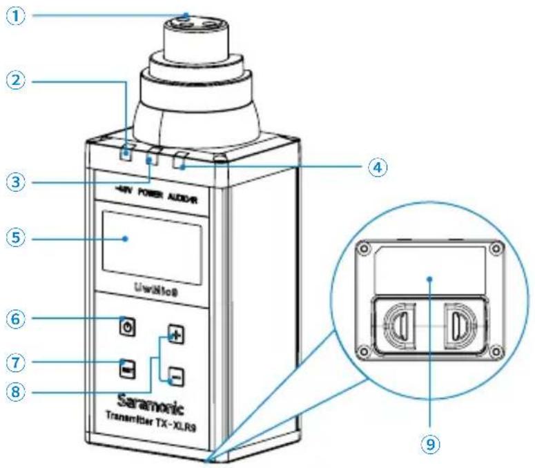
① XLR audio input jack Connects to an XLR microphone or audio devices with line output.
② +48V power indicator Lights up when the +48V phantom power is on.
③ POWER indicator Indicates the battery level as follows: Solid Green: Sufficient battery level. Solid Red: Low battery.
④ AUDIO indicator / IR (infrared detector) AUDIO indicator: Indicates the audio input level. IR (infrared detector): Gets the frequency from the receiver. Solid Green: Audio input level is appropriate. Flashing Red: Audio is muted (i.e., disabled). For details on setting the mute function, please refer to "Set Mute key" (page 20).
⑤ LCD screen
Displays menus, please refer to "LCD Display Operation Guide" (page 18) for more details.
⑥ Power / Mute button
Turns the power or mute function to on or off.
| Function Operation | |
| Power ON Press the button for one second or longer | |
| Power OFF Press the button until it turns off | |
| Mute ON | Short press the button |
| Mute OFF | |
⑦ SET button
Long press the SET button to enter the displayed menu. Then short press the SET button to confirm your option or long press again to exit without saving.
⑧ + or - button
Selects functions or values shown on the display.
⑨ Battery Compartment
Operates on two AA batteries (alkaline, nickel metal hydride, or lithium batteries). For details on how to insert batteries, please refer to "Install the batteries" (page 32).
Attaching Accessories

1. Attach a microphone or XLR cable.
Push the microphone or cable connector into the XLR audio input jack of the TX-XLR9 until it clicks into place.

2. Disconnect a microphone or XLR cable.
Press the release button and pull the microphone or XLR cable out carefully in the direction of arrow.
Note: Please turn off the transmitter before attaching or removing the microphone.
LCD Display Operation Guide

Home screen. If no operation is performed for 20 seconds on the other screens, the display will automatically return to the home screen.
① RF transmission power indicator
Indicates the current transmission power level.
For details on setting the level, please see "Select RF power level" (page 20).
② Channel group indicator
Indicates the channel group.
③ Mute indicator

Mute OFF

Mute ON
④ Battery level indicator
Displays the battery level. Please replace both batteries immediately when the indicator starts flashing.
⑤ Name of the channel group
⑥ Channel and frequency
Indicate the current channel and frequency.
⑦ The status of Power / Mute button

① Menu display section. Displays various functions. Press the + or - button to switch functions.
Set Power key. Select Unlocked or Locked.
Set "Locked" to lock the power button to prevent the unit being turned off or muted unwittingly while using. Default is "Unlocked."
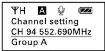
Select Channel. Long press the SET button to enter the menu. Use the "+" and "-" to select the channel you need and shot press the SET button to confirm.

Select Group. You can choose "A" or "B" channel group. Each group has 96 channels. Default is "Group A."

Set the microphone drive power supply (+48V). When set to ON, 48V phantom power is supplied to the connected microphone and the "+48V" indicator lights up. Default is "+48V OFF."
Note: Please DO NOT turn on the phantom power when using with microphones that do not operate on phantom power, mixing boards or any unbalanced devices, because it may cause damage to both transmitter and audio device.
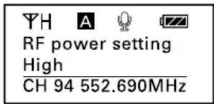
Select RF power level. You can set the transmitted RF power to High, Middle or Low. Default is "High."

Set Mute key. If you want to mute the audio, please select "Enable" first and then short press the power button. Default is "Enable."

IR Match. Set to match with the receiver. The screen will display "Matching" when in process. After successful matching, it will indicate "Sync finished."

Set Backlight. Select ON, OFF or Delay 10 / 30 /60 seconds. Default is "Delay 10s."

Version of the UwMic9-TX-XLR9.

Serial Number.
Plug-on Receiver UwMic9 RX-XLR9
Introduction
The Saramonic UwMic9 RX-XLR9 is a compact XLR plug-on wireless receiver. It plugs directly into a video camera or recorder's XLR microphone input without getting in the way of other accessories. The XLR connector rotates both clockwise and counter clockwise.
The receiver can be powered by two AA batteries or DC power via the USB Type-C jack. It features a wide switching RF bandwidth, an easy-to-read LCD screen, a 3.5mm headphone jack and infrared synchronization between transmitter and receiver.
Product Structure
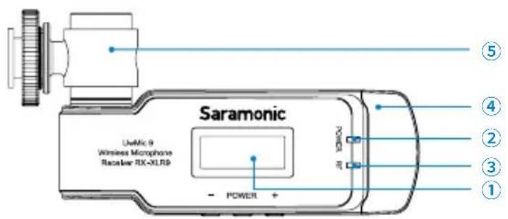
① LCD display Display menus, please refer to "LCD Display Operation Guide" (page 23) for more details.
② Power indicator Indicates the battery level as follows:
Green light: Sufficient battery level.
Red light: Low battery level.
③ RF indicator and infrared transmitter port
The infrared transmitter port sends the set frequency to a transmitter.
RF indicator displays the RF input level as follows:
Green light: RF signal is strong.
Red light: RF signal is weak or disconnected.
④ Antenna
⑤ Rotatable XLR-3-11C type (male) connector
Connects the receiver to a camera or recorder's XLR mic input. The receiver can be rotated by a maximum angle of 320irc .
⑥ Phone jack
It is a 3.5mm diameter and stereo mini headphone jack.
Connect a headphone to monitor the audio output.
Note: Please do not connect a headphone with a monaural mini jack. As this may short-circuit the headphone jack and distorted sound output.
⑦ + or - button
Selects functions or values shown on the display.
Long press the "-" button to enter the displayed menu.
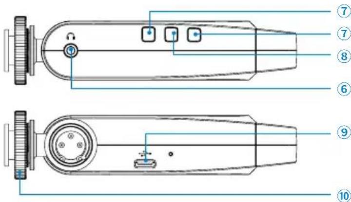
⑧ Power button
Long press to turn on or off the receiver.
Short press the power button to confirm your option.
⑨ USB connector (Type-C)
When a USB portable power supply is connected while the receiver is turned on, it automatically operates with the power supplied by the USB portable power, no matter AA batteries are inserted or not.
When a USB portable power supply is connected while the receiver is turned off, it automatically turns on.
Note: When the USB portable power supply is loosen and unconnected, the receiver will be powered by AA batteries automatically, but if no AA batteries were inserted, it will be turned off.
⑩ Standard cold shoe
Attaching Accessories
To mount the receiver to a video camera, proceed as follows:
- Slide the cold shoe mount onto the hot shoe of the DSLR camera as shown, and fasten the cold show mount using the locking screw.

natural_image
Line drawing of a DSLR camera with a blue scroll wheel (no text or symbols)-
Plug the receiver's rotatable XLR connector into the cold shoe adapter.
-
Connect the receiver to the mic jack of the camera with the supplied XLR to 3.5mm audio cable.

natural_image
Diagram of a DSLR camera with attached cable and connector, showing blue directional arrows indicating motion (no text or symbols)LCD Display Operation Guide
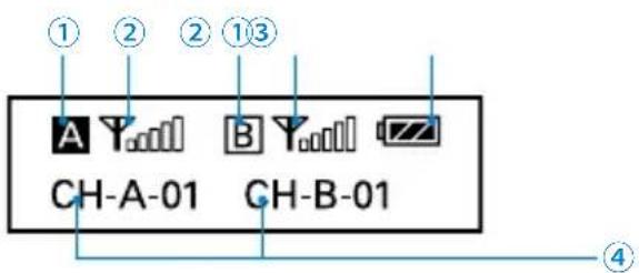
Home screen. If no operation is performed for 20 seconds on the other screens, the display will automatically return to the home screen.
① Group icon
A Indicates the power of group A is turned off.
A Indicates the power of group A is turned on.
② RF level indicator
Indicates the current reception level.
③ Battery level indicator
Displays the battery level. Please replace both batteries immediately when the indicator starts flashing.
④ Channel group and channel number
Displays the current channel number in Group A and Group B. "CH-A-01" means the Group A is in channel 01 now.

Power key. Long press the "-" button to enter the displayed menu. Use the "+" or "-" button to select locked or unlocked the power key and confirm it by pressing the POWER button. Lock the power key to prevent the receiver being turned off unwittingly while using.
Unlocked: Long press the power key to turn the receiver on or off (System default).
Locked: The receiver will not be turned off even after pressing the power key.

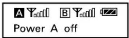
Power of the Group. When you only use one group signal, please turn off the other group to save battery. System default of the Group B is power off while the Group A is power on. When operating two transmitters simultaneously, please set each transmitter to a different group to prevent interference or noise.


Select channel. Long press the "-" button to enter the displayed menu. Use the "+" or "-" button to select the desired channel and confirm it by pressing the POWER button.
Default is Group A in Channel 01 (514.56MHz) and Group B in Channel 01 (556.51MHz).

Set output volume. Set the volume of output audio within the range 0 to 30. The setting is retained even after the power is turned off. Default is 27.

Auto scan function. Automatically scan an available and clear channel. Details of operation, please refer to "Using the auto scan function" (page 34).

Infrared matching function. Match the receiver and transmitter via infrared. Details of operation, please refer to "Match the channel of receiver and transmitter" (page 35).

Set backlight. Set the background LED light to ON or Delay 60/30/10 seconds or OFF. Default is "Delay 10s."
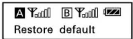
Version of the UwMic RX-XLR9.

Serial number.
UwMic9 SP-RX9
Introduction
The SP-RX9 is a compact two-channel wireless receiver and mixer, ideal for making videos with iOS or Android mobile devices and cameras. It can be used when paired with transmitters in UwMic9 system to capture audio. Meanwhile, it is an independent audio mixer that has three inputs available.
With built-in li-on battery, the receiver can be also powered by DC power via the USB Type-C connector. It comes with an aluminum handgrip for recording on the move, or it can be mounted on a tripod for stationary use. The standard shoe mount on the top of the receiver is suitable for attaching accessories.
Product Structure

① Antennas
② Power button
Long Press to turn on or off the SP-RX9.
③ SET button
Long press the SET button to enter the displayed menu. Then, short press the SET button to confirm your option or long press again to exit without saving.
④ POWER indicator
Indicates the battery level as follows:
Green light: Sufficient battery level.
Red light: Low battery level.
⑤ RF indicator and infrared transmitter port
The infrared transmitter port sends the set frequency to a transmitter.
RF indicator displays the RF input level as follows:
Green light: RF signal is strong.
Red light: RF signal is weak or disconnected.
⑥ + or - button
Selects functions or values shown on the display.
⑦ LCD display
Display menus, please refer to "LCD Display Operation Guide" (page 28) for more details.

⑧ 3.5mm microphone inputs
⑨ Phone jack
It is a 3.5mm diameter and stereo mini headphone jack. Connect a headphone to monitor the audio output.
Note: Please do not connect a headphone with a monaural mini jack. As this may short-circuit the headphone jack and distorted sound output.
⑩ USB connector (Type-C)
⑪ Output jack (Micro USB)
Connect the receiver to an iOS device with lightning input or an Android mobile device with Type-C connector.
⑫ Mini XLR microphone input
⑬ Output jack (3.5mm)
Connect the receiver to an iOS, Android mobile device or camera with a 3.5mm input.
⑭ Device holder
Adjustable phone holder
⑮ Thumb screw
⑯ Standard cold shoe mount
natural_image
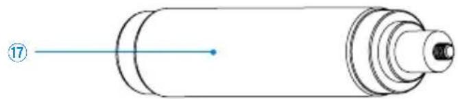
Pure diagram of a cylindrical object with internal layered structure and a numbered label (17), no text or symbols present.⑰ Hand grip
LCD Display Operation Guide

Home screen. If no operation is performed for 20 seconds on the other screens, the display will automatically return to the home screen.
① Group icon
A Indicates the power of group A is turned off.
A Indicates the power of group A is turned on.
② RF level indicator
Indicates the current reception level.
③ Battery level indicator
Displays the battery level. Please charge the receiver immediately when the indicator starts flashing.
④ Name of the channel group
⑤ Current channel
Displays the current channel number.
⑥ Audio input level meter
Displays the audio input level.

Power key. Long press the SET button to unlocked or locked the power key. Lock the power key to prevent the receiver being turned off unwittingly while using.
- Unlocked: Long press the power key to turn the receiver on or off (System default).
- Locked: The receiver will not be turned off even after pressing the power key.

Output mode. The output mode can be selected to mono or stereo. When the output mode is mono, the audio from left and right channel will be mixed.
When it is stereo, the audio will be separated into left and right channel. The wireless transmitter microphone on Group A and the audio from INPUT 1 will be on left channel.
System default is mono.
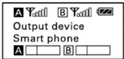
Output device. The output device can be selected to smart phone or camera. System default is smart phone. Remember to change it to "camera" when connecting the SP-RX9 to a video camera or camcorder.

48V Phantom power. Long press the SET button to turn on the 48V phantom power if the XLR microphone requires power supply. System default is power off.
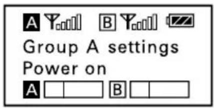

Power of the Group. When you only use one group signal, please turn off the other group to save battery. To save battery, system default of the Group B is power off while the Group A is power on.
When operating two transmitters simultaneously, please set each transmitter to a different group to prevent interference or noise.


Select channel. Details of operation, please refer to "Manually setting the receiver channel" (page 35).
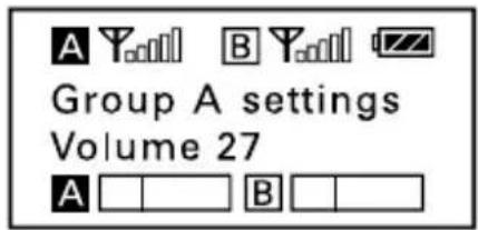
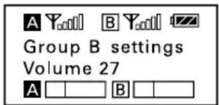
Set output volume. Set the volume of output audio within the range 0 to 30. The setting is retained even after the power is turned off. Default is 27.
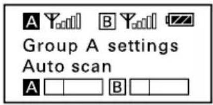
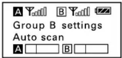
Auto scan function. Automatically scan an available and clear channel. Details of operation, please refer to "Using the auto scan function" (page 34).


Infrared matching function. Match the receiver and transmitter via infrared. Details of operation, please refer to "Match the channel of receiver and transmitter" (page 35).

Set backlight. Set the background LED light to ON or Delay 60 /30 /10 seconds or OFF. Default is "Delay 10s."
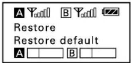
Version number of the receiver.

Serial Number.
Operation Guide
1. Install the batteries
① UwMic9-RX9 and UwMic9-TX9. Batteries can be inserted in the plug-on transmitter UwMic9-TX-XLR9 in the same manner.

- Long press the Power key to turn the unit off.
- Slide the two catches inward and pull out the battery compartment.
- Insert two AA size batteries according to the polarity indicators and close the compartment. Please be sure the battery compartment is locked securely.
② UwMic9-HU9

natural_image
Diagram of two handheld devices with blue arrows indicating movement or change, no text or symbols present- Long press the power button to turn the power off.
- Turn the grip in the direction of the arrow, and pull the grip down until the battery compartment is visible.
- Insert two new AA batteries into the battery compartment with ⊕ and ⊖ polarities in the correct orientation.
③ UwMic9 RX-XLR9

natural_image
Line drawing of a mobile phone casing with a blue arrow indicating the direction (no text or symbols)- Long press the power button turn the unit off.
- Gently slide out the battery cover by pushing the button as shown.
- Insert two new AA batteries into the battery compartment with the polarities in correct orientation.
Note:
① Please remove the batteries from the battery compartment when the device is not used for a long time.
② Please always use sets of the same type of battery.
③ Replacing the batteries during operation may generate noise. Please make sure that the unit is turned off before replacing batteries.
- Connect the receiver to the mic jack of a camera, camcorder or mixer with the supplied cable.
- Turn on the receiver by long pressing the power button.
- Set the channel of the receiver by two ways:
① Using the auto scan function
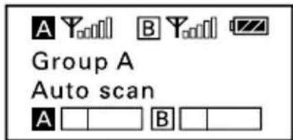
Use the + or - button to display the auto scan screen on the receiver.

Long press the SET button to select "Auto scan?"

Press the SET button to confirm.
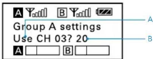
The channel with the least noise and interference will be displayed.
A. Indicates the current least noise channel is CH 03 and ask you if you would like to use it. You can short press the SET button to confirm the channel within 20 seconds or long press the SET button to exit the displayed menu without saving.
B. Counting down 20 second
Note:
① After 20 seconds have elapsed, the display returns to the home screen without saving.
② Some noise may occur when power is turned on, you could turn down the audio input level of devices connected to the receiver accordingly.
② Manually setting the receiver channel.
- Use the + or - button to display the channel menu on the receiver.
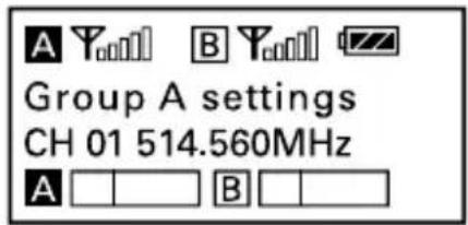
- Long press the SET button to select the menu.

- Use the + or - button to select the desired channel and confirm it by short pressing the SET button.
5. Match the channel of receiver and transmitter.
① Using infrared transmission to transfer the frequency set on the receiver to a transmitter.
For the TX9 and TX-XLR9
• Turn on the transmitter and receiver.
- Use the + or - button to display the "Match with TX" menu on receiver.

- Use the + or - button to display the "Match with RX" menu on transmitter.

- Both long press the SET button to select the menu and short press it to confirm.
- Place the infrared transmitter port on the receiver near the infrared detector on the transmitter.
- If "Sync finished!" displayed on the LCD screen, the frequency for use on the transmitter is set.
- After matching successfully, press the SET button of receiver to return to the previous menu.
For HU9
- Turn the transmitter power on.
- Use the + or - button to display the "Match with TX" menu on receiver.
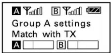
- Place the infrared transmitter port on the receiver near the infrared detector on the transmitter.
- If sync successfully, the group and channel of HU9 are the same as the receiver's.
• After matching successfully, press the SET button of receiver to return to the previous menu.
Note: When using the infrared link, please place the receiver and transmitter within about 20cm of each other within 20 seconds. After 20 seconds have elapsed, the infrared transmission finishes and the display returns to the previous menu.
② Manually setting the transmitter channel (Only available on the UwMic9-TX9 and the UwMic9-TX-XLR9).
- Turn on the transmitter by long pressing the power button.
- Use the + or - button to display the channel setting menu on the transmitter.
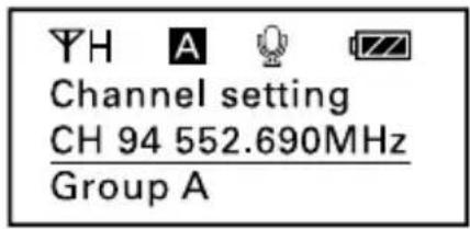
- Long press the SET button to select the menu.
- Use the + or - button to select the same channel as the receiver and confirm it by short pressing the SET button.
-
Attach the accessories you need for the receiver and transmitter. Refer to "Attaching Accessories" (page 4, page 10, page 17 and page 23).
-
You are ready to record.
Specification
Receiver RX9 and RX-XLR9
| Channel number 96 | |
| Channel group A and B | |
| Oscillator type PLL synthesizer | |
| Audio output connector | RX9: 3.5 mm mini jack |
| RX-XLR9: XLR-3-11C type (male) | |
| Antenna 1/4 | λ wire antenna |
| Audio output level -60 dBV | |
| Headphone output level 30mW (16 Ω) | |
| Receive frequencies 514 MHz - 596 MHz | |
| Receive sensitivity -95 dBm | |
| Signal to noise ratio 70 dB or more | |
| Voice delay 12 ms | |
| Reference deviation ±5 kHz (-60 dBV, 1 kHz input) | |
| Frequency response 40 Hz to 18 kHz (+/-3dB) | |
| Distortion | 0.5% or less |
| Spur suppression | -60 dB |
| Reference audio input level | -60 dBV (MIC input, 0 dB attenuation) |
| Weight (excluding batteries) | RX9: Approx. 218.7g |
| RX-XLR9: Approx. 96g | |
| Battery | Two AA size batteries |
| DC input connector | Type-C jack (RX-XLR9 only) |
| Dimensions | RX9: 170.9 × 63.5 × 30.0 mm |
| RX-XLR9: 112 × 63 × 26 mm | |
| Operating temperature 0 °C to 50 °C | |
| Storage temperature -20 °C to +55°C | |
Transmitter TX9, HU9 and TX-XLR9
| Channel number 96 | |
| Channel group A or B | |
| Oscillator type PLL synthesizer | |
| Carrier frequencies 514 MHz - 596 MHz | |
| Reference deviation ±5 kHz (-60 dBV, 1 kHz input) | |
| Signal to noise ratio 70 dB or more | |
| Spur suppression -60 dB | |
| Voice delay 12 ms | |
| Antenna 1/4 | λ wire antenna |
| Audio input connector | TX9: 3.5mm mini jack |
| HU9: none | |
| TX-XLR9: XLR-3-11C type (female) | |
| Reference audio input level -60 dBV (MIC input, 0 dB attenuation) | |
| Distortion 0.5% or less | |
| Weight | TX9: Approx. 211.4g (excluding batteries) |
| HU9: Approx. 338.2g (excluding batteries) | |
| TX-XLR9: Approx. 138g (Excluding batteries) | |
| Battery Two AA size batteries | |
| Dimensions | TX9: 170.9 × 63.5 × 30.0 mm |
| HU9: 254.0 × 52.0 × 52.0 mm | |
| TX-XLR9: 105.5 × 43 × 34.7 mm | |
| Operating temperature 0°C to 50°C | |
| Storage temperature -20°C to +55°C | |
Receiver SP-RX9
| Channel number 96 | |
| Channel group A or B | |
| Oscillator type PLL synthesizer | |
| Receive frequencies | 514 MHz - 596 MHz |
| Audio input connector | Two 3.5 mm mini jacks and one mini XLR jack |
| Audio output connector | One 3.5 mm mini jack and one Micro USB |
| Headphone output connector | 3.5 mm mini jack |
| INPUT 1 gain | 20 dB |
| INPUT 2 & mini XLR gain 20 dB | |
| Micro USB gain 20 dB | |
| INPUT 1 & INPUT 2 power 5V power supplies | |
| Mini XLR jack phantom power 48V power supplies | |
| Antenna Built-in 1/4 | λ wire antenna |
| Audio output level -60 dBV | |
| Headphone output level 30 mW (16 Ω) | |
| Receive sensitivity -95 dBm | |
| Signal to noise ratio 70 dB or more | |
| Voice delay 12 ms | |
| Reference deviation ±5 kHz (-60 dBV, 1 kHz input) | |
| Frequency response 40 Hz to 18 kHz (+/-3 dB) | |
| Distortion 0.5% or less | |
| Spur suppression -60 dB | |
| Battery Built-in Li-ion battery (1200 mA) | |
| Power DC 5V (USB Type-C) | |
| Dimensions | 100.0 × 38.6 × 259.6 mm (Including the hand grip) |
| Device holder width | 66.4 mm to 84.1 mm (26.1" to 33.1") |
| Weight | Approx. 433 g (Including the hand grip) |
| Operating temperature 0 °C to 50 °C | |
| Storage temperature | -20 °C to +55°C |
Packing list
natural_image
Technical line drawings of a radio device, a handheld microphone, and two separate clamps (no text or symbols)TX9
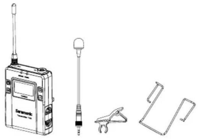
• Body-pack transmitter: TX9
- Omni-directional lavalier microphone
- Microphone holder clip
- Wind screen
- Belt clip
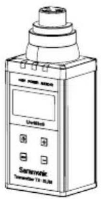
TX-XLR9
- Plug-on transmitter: TX-XLR9

natural_image
Line drawing of a handheld electronic device with a square button and handle (no text or symbols)HU9
• Hand-held microphone: HU9

natural_image
Technical line drawings of various electronic devices including a walkie-talkie, camera, and coiled spring (no text or symbols present)RX9
- Portable receiver: RX9
- Shoe mount adapter
- Belt clip
- XLR to 3.5mm locking-type plug audio output cable
• 3.5mm locking-type plug audio cable

RX-XLR9
- Plug-on receiver: RX-XLR9
- Shoe mount adapter
• XLR to 3.5mm audio output cable - Typc-C charging cable

SP-RX9
- Wireless receiver and mixer: SP-RX9
- Hand grip
• USB Type-A to Type-C charge cable - Micro USB to USB Type-C cable
- Micro USB to Lightning cable
• 3.5mm TRRS to TRRS audio output cable - Mini XLR to standard XLR cable
Warranty card
User manual
www.saramonic.com
The Saramonic logo is trademark which is registered and owned by Saramonic International.
COPYRIGHT 2011-2021 SARAMONIC INTERNATIONAL (A
brand of DSQN)
Email: info@saramonic.com

- Cautions
- Contents
- General Introduction....2
- Portable Receiver UwMic9-RX9 2
- Body-pack Transmitter UwMic9-TX9....9
- Hand-held Microphone UwMic9-HU9 14
- Plug-on Transmitter UwMic9-TX-XLR9....16
- Plug-on Receiver UwMic9 RX-XLR9 21
- UwMic9 SP-RX9 26
- Operation Guide 32
- Specification.... 37
- Packing list....40
- General Introduction
- Portable Receiver UwMic9-RX9
- Introduction
- Product Structure
- Attaching Accessories
- Attach a belt clip. Please Refer to "Attaching Accessories" (page 11).
- Attach the shoe mount adapter.
- LCD Display Operation Guide
- Attach a belt clip
- Connect the microphone
- Hand-held Microphone UwMic9-HU9
- Setup Guide
- Plug-on Transmitter UwMic9-TX-XLR9
- Attach a microphone or XLR cable.
- Disconnect a microphone or XLR cable.
- Plug-on Receiver UwMic9 RX-XLR9
- UwMic9 SP-RX9
- Operation Guide
- Install the batteries
- Note:
- Match the channel of receiver and transmitter.
- For the TX9 and TX-XLR9
- For HU9
- Specification
- Packing list
- TX9
- TX-XLR9
- HU9
- RX9
- RX-XLR9
- SP-RX9
Brand : Saramonic
Model : UwMic9
Category : Receiver