
UR28M - Hi-Fi System STEINBERG - Free user manual and instructions
Find the device manual for free UR28M STEINBERG in PDF.


| Product Type | Hi-Fi Audio Interface with DSP Mixer |
| Brand | Steinberg |
| Model | UR28M |
| Power Supply | DC 12V via external AC adaptor |
| Microphone Preamps | 2 high-resolution D-Pre with inverted Darlington circuit |
| Phantom Power | +48V switchable per channel (via +48V button) |
| HI-Z Input | Yes, switchable for electric guitar/bass |
| PAD | -26 dB switchable for high-level sources |
| Analog Inputs | 2 XLR/TRS combo (Mic/Line/HI-Z), 2 TRS line (LINE INPUT 3/4) |
| Digital Inputs | 1 coaxial S/PDIF (with SRC) |
| Analog Outputs | 3 pairs TRS line outputs (LINE OUTPUT A-C), 2 headphone jacks (1/4") |
| Digital Outputs | 1 coaxial S/PDIF |
| Monitor Control | Volume, Mute, Mono Mix, Dimmer (-20 dB), Alternate/Independent modes for 3 speaker sets |
| DSP Mixer | dspMixFx: 6 input channels to 3 stereo mixes, zero-latency hardware monitoring |
| DSP Effects | Sweet Spot Morphing Channel Strip (Compressor + 3-band EQ) and REV-X Reverb (Hall, Room, Plate) |
| Included Software | Cubase AI DAW, VST plug-in versions of Channel Strip and REV-X |
| Sample Rates | 44.1, 48, 88.2, 96 kHz |
| USB Connection | USB 2.0 |
| Word Clock | Internal or S/PDIF input, selectable |
| Maintenance | Clean with dry cloth; avoid moisture and liquids |
Frequently Asked Questions - UR28M STEINBERG
User questions about UR28M STEINBERG
0 question about this device. Answer the ones you know or ask your own.
Ask a new question about this device
Download the instructions for your Hi-Fi System in PDF format for free! Find your manual UR28M - STEINBERG and take your electronic device back in hand. On this page are published all the documents necessary for the use of your device. UR28M by STEINBERG.
USER MANUAL UR28M STEINBERG
Contents in this Operation Manual.... 3
Features 3
Panel Controls and Terminals (Details)......4
Rear Panel....4
Front Panel 6
Panel Controls for the Software Programs .....9
Control Panel of the Audio Driver....9
dspMixFx UR28M....10
Dedicated Windows for Cubase Series 16
Sweet Spot Morphing Channel Strip (Channel Strip). 20
REV-X 23
Usage Examples....25
Introduction 25
Recording with the Channel Strip and REV-X...... 25
Controlling the Monitor Sound 26
Using the Device Without a Computer.... 27
Appendix 28
Glossary 28
Contents of the Getting Started Section 29
Signal Flow....30
Block Diagrams.... 32
Introduction
Contents in this Operation Manual
This Operation Manual explains how to use the device. The explanations in this manual assume that you've set up the device and prepared it for use according to the included Getting Started document. If you haven't done that yet, refer to the Getting Started document and complete the setup before reading this manual.
Features
High-resolution Microphone Preamplifiers (D-Pre)
Discrete microphone preamps featuring a high-performance inverted Darlington circuit configuration achieve low distortion and noise while delivering sound with eminently musical balance and character.
Convenient Monitor Control
Up to three sets of monitor speakers can be connected to the unit, with versatile control of monitor output provided via convenient buttons and knobs: volume, mute, mono mix, and dimmer. There are two functions (modes) regarding monitor control: the Alternate mode, which lets you select a set of monitor speakers for signal output, and the Independent mode, which lets you select the signals for outputting to each set of monitor speakers simultaneously.
Supports a Variety of Inputs
Switchable phantom power is provided for condenser microphones, electric guitars and basses can be directly connected via a HI-Z (high impedance) input, and a PAD is provided for input matching with high-level signals from electronic instruments. A stereo mini-jack 2TR IN input provides a convenient way to connect portable music players, and coaxial S/PDIF connectors enable direct connection to a variety of digital audio devices.
Powerful DSP Mixer (dspMixFx)
A DSP mixer that can mix up to six input channels to three stereo outputs is built in. A number of DSP effects that can be applied to input signals are also provided, and since it is a hardware mix with there is no monitoring latency.
DSP Effect: Sweet Spot Morphing Channel Strip
The Sweet Spot Morphing Channel Strip ("Channel Strip" for short) is a multi-effect that combines compression and EQ. Advanced sound engineering know-how is condensed into a number of presets that can simply be recalled as required for professional results. Four channel strips are provided, and each can be assigned to the monitor sound only, or to both the monitor and recorded sound.
DSP Effect: REV-X Reverb
REV-X is a digital reverb platform developed by Yamaha for pro audio applications. One REV-X effect is included in this unit. Input signals can be sent to the REV-X effect, and the REV-X effect is applied only to the monitor outputs.
DSP Effect VST Plug-ins Included
VST Plug-in (VST3.0, page 28) versions of the Channel Strip and REV-X effects are included for use with Cubase series or similar VST-compatible DAW software.
Cubase AI Included
Steinberg Cubase AI digital audio workstation (DAW, page 28) software is included. Cubase AI is the entry-level version of the Cubase series DAW products, providing the basic functionality you need for music production and editing.
Panel Controls and Terminals (Details)
Rear Panel
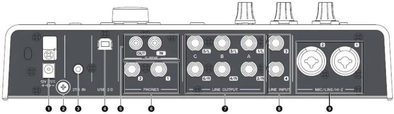
① DC IN 12V
For connection to the AC power adaptor.
② Grounding screw
For connection to a ground wire.
If you have a problem with hum or noise, use this terminal to connect to ground. The noise may be reduced.
③ 2TR IN (3.5 mm, stereo)
For connection to a portable audio player.
The input signal at 2TR IN flows only to MIX 1 (page 28), and not to the computer.
④ USB2.0 (USB port)
For connection to a computer.
⑤ S/PDIF IN/OUT (coaxial)
For connection to a digital audio device.
S/PDIF OUT outputs one of the MIX 1–3 and DAW OUT signals. To select the output signal, use the "Setup Window" (page 15) in the section "dspMixFx UR28M" or the "Output Routing Window" (page 20) in the section "Dedicated Windows for Cubase Series".
S/PDIF IN is equipped with the SRC (Sampling Rate Converter) function. Even if the sampling rate at which the device is operating differs from the sampling rate of the audio signal input to the S/PDIF IN, the SRC function will automatically convert the rate so that playback will be correct. SRC is only available when INTERNAL is selected as the clock source of the device. To select the clock source of the device, use the "(device name) Window" (page 9) in the section "Control Panel of the Audio Driver" in Windows or Audio MIDI Setup in Mac.
⑥ PHONES 1/2 (phone type, stereo)
For connection to a set of headphones.
PHONES 1 outputs the MIX 1 signal. PHONE 2 outputs one of the MIX 1–3 signals. To select the output signal of PHONES 2, use the "Headphone Area" (page 14) in the section "dspMixFx UR28M" or the "Headphones Window" (page 19) in the section "Dedicated Windows for Cubase Series."
⑦ LINE OUTPUT A-C (phone type, balanced/unbalanced)
For connection to monitor speakers. When the monitor speakers have a balanced input, connect them with a balanced cable.
There are two functions (modes) on LINE OUTPUTS A–C: Alternate and Independent. In the Alternate mode, one of the LINE OUTPUTS A–C selected by the OUTPUT buttons A–C outputs a single MIX signal selected by the SOURCE SELECT button. In the Independent mode, LINE OUTPUTS A–C output each MIX selected by the SOURCE SELECT button simultaneously.
For details on the mode, including how to select the mode, refer to the "Setup Window" (page 15) in the section "dspMixFx UR28M" or the "Master Levels Window" (page 20) in the section "Dedicated Windows for Cubase Series."
⑧ LINE INPUT 3/4 (phone type, balanced/unbalanced)
For connection to a digital instrument.
You can select the input signal level of LINE INPUT 3/4 between "+4dBu" and "-10dBV." Select "+4dBu" when connecting a professional audio device, and select "-10dBV" when connecting a consumer device. The default initial setting is "+4dBu." To select the input signal level, use the "Setup Window" (page 15) in the section "dspMixFx UR28M" or the "Settings Window" (page 20) in the "Dedicated Windows for Cubase Series."
⑨ MIC/LINE/HI-Z 1/2 (XLR/phone type, balanced/unbalanced)
For connection to a microphone, digital instrument, electric guitar, or electric bass.
Front Panel
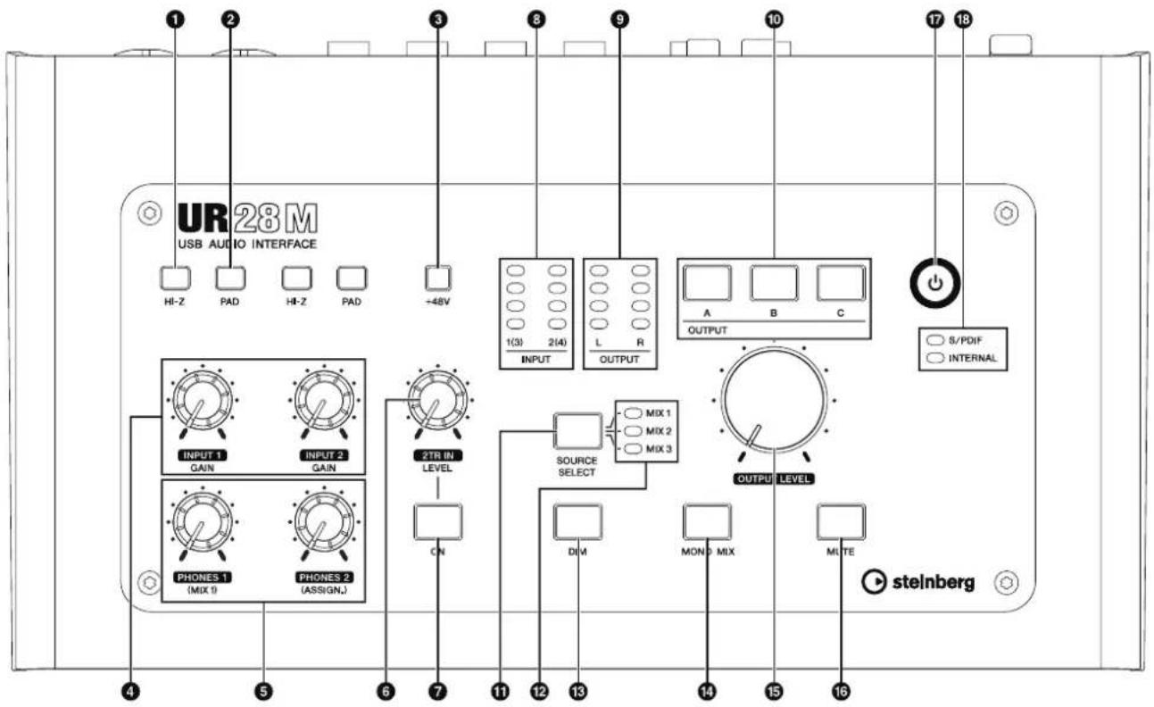
① HI-Z switch
Turns on (■) and off (■) the HI-Z of the MIC/LINE/HI-Z.
Turn this switch on when connecting high impedance instruments, such as an electric guitar or electric bass, directly to the MIC/LINE/HI-Z.
When you turn this switch on, use an unbalanced phone cable for connection between the instruments and the MIC/LINE/HI-Z. If you use a balanced cable or an XLR cable, this device will not work correctly.
CAUTION
- Do not connect or disconnect a device while turning on the HI-Z switch. Doing so can damage the connected device and/or the unit itself.
- To protect your speaker system, leave the monitor speakers turned off when turning the HI-Z switch on/off. It's also a good idea to turn all output volume controls down to their minimum. Neglect of these precautions may result in large noise bursts that may damage your equipment, your ears, or both.
② PAD switch
Turns on (■) and off (■) the PAD of the MIC/LINE/HI-Z.
When you turn this switch on, the input signal level of the MIC/LINE/HI-Z will be attenuated by 26 dB. Turn this switch on when connecting high output equipment, such as a synthesizer, to the MIC/LINE/HI-Z.
③ +48V button
Turns on (lit) and off (dark) the phantom power of the MIC/LINE/HI-Z 1 and 2 (XLR type).
When you turn this button on, phantom power will be supplied to the MIC/LINE/HI-Z 1 and 2. Turn this button on when connecting phantom powered devices, such as a condenser microphone, to the MIC/LINE/HI-Z 1/2.
CAUTION
- Make sure that phantom power is turned OFF unless it is needed.
- When turning phantom power ON, make sure that no equipment other than phantom-powered devices such as condenser microphones are connected. Devices other than condenser microphones may be damaged if connected to the phantom power supply. Note, however, that the switch may be left on when connecting to balanced dynamic microphones. When connecting an unbalanced device to the MIC/LINE/HI-Z 1/2 and phantom power is turned on, hum or noise may result; this is not a malfunction or failure in the device.
- Do not connect or disconnect a device while phantom power is applied. Doing so can damage the connected device and/or the unit itself.
- To protect your speaker system, leave the monitor speakers turned off when switching the phantom power on/off. It's also a good idea to turn all output volume controls down to their minimum. Neglect of these precautions may result in large noise bursts that may damage your equipment, your ears, or both.
④ INPUT GAIN knob 1/2
Adjusts the input signal level of the MIC/LINE/HI-Z 1/2. The adjustable range varies depending on the on/off setting of the PAD switch.
PAD Range
On -34 dB - +10 dB
Off -60 dB --16 dB
⑤ PHONES knob 1/2
Adjusts the output signal level of the PHONES 1/2. This output signal level is not affected by the OUTPUT LEVEL knob.
PHONES 1 outputs the MIX 1 signals. PHONE 2 outputs one of the MIX 1–3 signals. To select the output signal of the PHONES 2, use the "Headphone Area" (page 14) in the section "dspMixFx UR28M" or the "Headphones Window" (page 19) in the section "Dedicated Windows for Cubase Series."
⑥ 2TR IN LEVEL knob
Adjusts the input signal level of the 2TR IN signal. The input signal at 2TR IN flows only to MIX 1, and not to the computer.
⑦ 2TR IN ON button
Turns on (lit) and off (dark) the 2TR IN.
8 INPUT meter
Indicates the input signal level of the analog input jacks (MIC/LINE/HI-Z 1/2 or LINE INPUT 3/4).
Lamp Description
○ Red Overload
○ Amber -3 dB or more
○ Amber -14 dB or more
○ Green -48 dB or more
To select which analog input jacks' levels are to be indicated, use the "Setup Window" (page 15) in the section "dspMixFx UR28M" or the "Settings Window" (page 20) in the section "Dedicated Windows for Cubase Series."
⑨ OUTPUT meter
Indicates the output signal level of the LINE OUTPUT selected by the OUTPUT button A–C.
Lamp Description
○ Red Overload
○ Amber -3 dB or more
○ Amber -14 dB or more
○ Green -48 dB or more
10 OUTPUT buttons A-C
For Alternate mode, this selects the particular LINE OUTPUT for output. For example, when you press OUTPUT button A, only LINE OUTPUT A will be selected for output, and OUTPUT button A will light.
For Independent mode, this selects the particular LINE OUTPUT for control. For example, when you press OUTPUT button A, LINE OUTPUT A will be selected for control, and OUTPUT button A will light.
For details on the mode, including how to select the mode, refer to the "Setup Window" (page 15) in the section "dspMixFx UR28M" or the "Master Levels Window" (page 20) in the section "Dedicated Windows for Cubase Series."
⑪ SOURCE SELECT button
For Alternate mode, this selects the output signal (MIX 1–3) of the LINE OUTPUT.
For Independent mode, this selects the output signal (MIX 1–3) of the LINE OUTPUT selected by OUTPUT buttons A–C.
For details on the mode, including how to select the mode, refer to the "Setup Window" (page 15) in the section "dspMixFx UR28M" or the "Master Levels Window" (page 20) in the section "Dedicated Windows for Cubase Series."
⑫ MIX 1-3 lamp
For Alternate mode, this indicates the output signal (MIX 1–3) of the LINE OUTPUT.
For Independent mode, this indicates the output signal (MIX 1–3) of the LINE OUTPUT selected by OUTPUT buttons A–C.
For details on the mode, including how to select the mode, refer to the "Setup Window" (page 15) in the section "dspMixFx UR28M" or the "Master Levels Window" (page 20) in the section "Dedicated Windows for Cubase Series."
13 DIM button
Turns on (lit) and off (dark) the dimmer of all LINE OUTPUT signals.
When you turn on this button, the output signal level of all LINE OUTPUT will be attenuated by 20 dB. Turning on and off this button will not affect the output signal level of PHONES 1/2.
14 MONO MIX button
For Alternate mode, this turns on (lit) and off (dark) the mono mix for the output signal of the LINE OUTPUT.
For Independent mode, this turns on (lit) and off (dark) the mono mix for the output signal of the LINE OUTPUT selected by OUTPUT buttons A–C.
You can confirm the phase or mix balance of the sound by using this button.
For details on the mode, including how to select the mode, refer to the "Setup Window" (page 15) in the section "dspMixFx UR28M" or the "Master Levels Window" (page 20) in the section "Dedicated Windows for Cubase Series."
15 OUTPUT LEVEL knob
Adjusts the output signal level of the LINE OUTPUT.
When you turn the LINK (page 15) off in the Independent mode, you can set different output signal levels to each LINE OUTPUT A–C. Press one of the OUTPUT buttons A–C then adjust the output signal level by the OUTPUT LEVEL knob. At this time, the OUTPUT LEVEL knob setting and the output signal level are mismatched immediately after you select the OUTPUT buttons A–C. When you adjust the OUTPUT LEVEL knob, the output signal level is applied immediately.
CAUTION
When you turn the LINK off, and set the a significant different signal level for each LINE OUTPUT A–C, a high volume level may be produced suddenly by turning the OUTPUT LEVEL knob, possibly causing hearing loss or device damage.
16 MUTE button
For Alternate mode, this turns on (lit) and off (dark) muting of the LINE OUTPUT signal.
For Independent mode, this turns on (lit) and off (dark) muting of the LINE OUTPUT signal selected by OUTPUT buttons A–C.
For details on the mode, including how to select the mode, refer to the "Setup Window" (page 15) in the section "dspMixFx UR28M" or the "Master Levels Window" (page 20) in the section "Dedicated Windows for Cubase Series."
17 Power button
Turns the power on and off.
Power on Press the power button (). The power button will light.
Power off Hold down the power button ( ) ⏻ for over one second. The power button will light dimly.
18 Word clock source lamp
Indicates the word clock (page 28) source of the device.
Lamp Clock Source
S/PDIF The word clock signal input to S/PDIF IN.
INTERNAL The internal word clock signal.
Lamp status Description
Lit Synchronized with the clock source.
Flash Not synchronized with the clock source.
To select the clock source of the device, use the "(device name) Window" (page 9) in the section "Control Panel of the Audio Driver" in Windows or Audio MIDI Setup in Mac.
Panel Controls for the Software Programs
Control Panel of the Audio Driver
This is the control panel for selecting the general settings of the audio driver. Click the upper tabs to select the desired window.
Screenshot
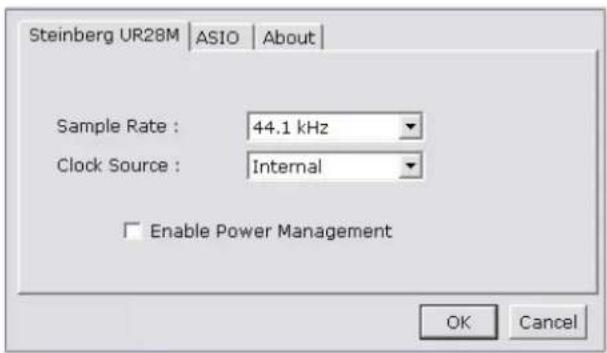
How to Open the Window
Windows
- [Start] → [Control Panel] → [Hardware and Sound] or [Sounds, Speech, and Audio Devices] → [Yamaha Steinberg USB Driver]
- From the Cubase series menu, [Devices] → [Device Setup] → [Yamaha Steinberg USB ASIO] → [Control Panel]
Mac
•[System Preferences] → [Yamaha Steinberg USB]
- From the Cubase series menu, [Devices] → [Device Setup] → [Steinberg UR28M] → [Control Panel] → [Open Config App]
Panel Controls
(Device name) Window
This is the window for selecting the sample rate or word clock source of the device.
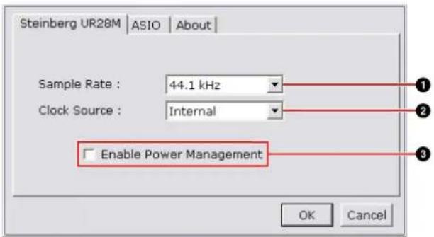
① Sample Rate (Windows only)
Selects the sample rate of the device.
Option: 44.1 kHz, 48 kHz, 88.2 kHz, 96 kHz
NOTE
For Mac, select the sample rate of the device via the Audio MIDI Setup.
② Clock Source (Windows only)
Selects the word clock source of the device.
Option Clock Source
S/PDIF The word clock signal input to S/PDIF IN.
Internal The internal word clock signal.
NOTE
For Mac, select the word clock source of the device via the Audio MIDI Setup.
③ Enable Power Management
Select enable (checkmark) and disable (no checkmark) for automatic power off.
The device is equipped with an automatic power off function. When this function is enabled, the power of the device will turn off automatically (after thirty minutes) when one of the following actions is performed. The power button will flash during the thirty-minute interval.
- Turning off the computer.
- Disconnecting the USB cable between the device and the computer.
ASIO Window (Windows only)
This is the window for selecting the ASIO driver settings.
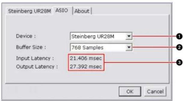
① Device
Selects the device that will be using the ASIO driver. This function is available when connecting to the computer two or more devices compatible with the Yamaha Steinberg USB Driver.
② Buffer Size
Selects the buffer size (page 28) for the ASIO driver. The range varies depending on the sample rate.
Sample Rate Range
48 kHz or lower 64 samples – 2048 samples
88.2 kHz or higher 128 samples - 4096 samples
NOTE
For Mac, select the buffer size in the buffer size selecting window, which is opened from an application such as DAW software.
③ Input Latency/Output Latency
Indicates the delay time for the audio input and output in millisecond units.
Audio latency varies depending on the value of the ASIO buffer size. The lower the value of the ASIO buffer size, the lower the value of Audio latency.
About Window
This window indicates information about the audio driver.
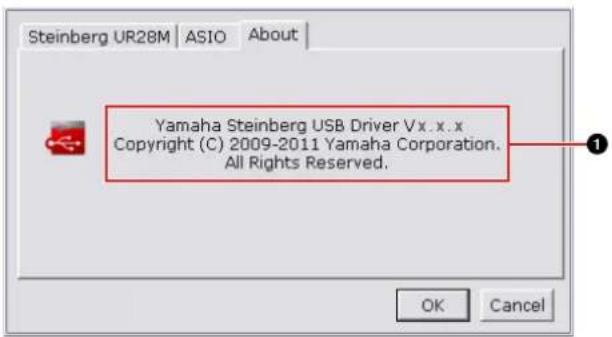
① About
Indicates the version and copyright of the audio driver. The letters "x.x.x" indicate the version number.
dspMixFx UR28M
This is the window for configuring the DSP mixer and DSP effect equipped with the device. The signals flow top-to-down and left-to-right. The dspMixFx UR28M provides stand-alone operation.
NOTE
You cannot operate the dspMixFx UR28M while a Cubase series DAW is running. When Cubase is running, configure the DSP mixer and DSP effect from "Dedicated Windows for Cubase Series" (page 16).
Screenshot
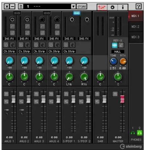
How to Open the Window
Windows
[Start] → [All Programs] → [Steinberg UR28M] → [dspMixFx UR28M]
Mac
[Macintosh HD] → [Applications] → [dspMixFx UR28M]
Panel Controls
Tool Area
This is the area for configuring the common settings of the dspMixFx UR28M.

① Quit
Quits the dspMixFx UR28M.
② Minimize
Minimizes the dspMixFx UR28M window.
③ Menu
Provides four menus, including Save the settings file of the dspMixFx UR28M (page 28) and Import Scene (page 28).
Menu Description
Open Opens the settings file of the dspMixFx UR28M.
Save Saves the settings file of the dspMixFx UR28M to a computer.
Import Scene Imports a scene from the settings file of the dspMixFx UR28M. Select the settings file of the dspMixFx UR28M and import scene on the left side of the IMPORT SCENE window. Select the destination for importing on the right side of the window. Click [OK] to import it.
Initialize All Deletes all the saved scenes. Scenes
4 Scene
Indicates the scene name. You can change the scene name by clicking on it.
When you click the button on the right side, the window for calling up the scene will open. You can call up the scene by clicking it. To cancel calling up the scene, click outside of the window.
⑤ STORE
Opens the scene store window. Enter the desired scene name into the STORE NAME field. Select the destination for storing the scene in the No. NAME field. Click [OK] to store the scene.
⑥ Selecting the window
Selects the dspMixFx UR28M window. The selected window icon will light in red.
Icon Description

Main window (page 12)

Setup window (page 15)

Information window (page 16)
7 Help
Opens the Operation Manual (this manual).
Main Window
This is the window for configuring the entire signal flow.
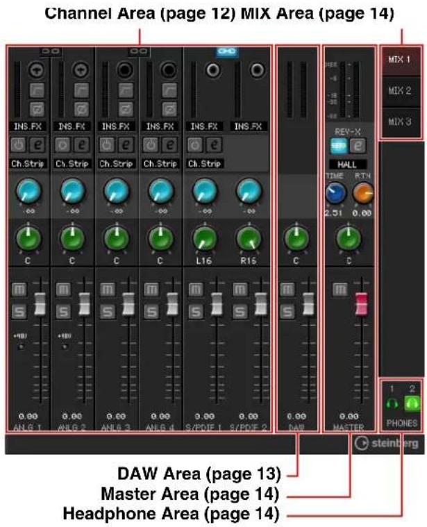
Channel Area
This is the area for configuring the input channel settings.
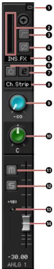
① Channel Link
Turns on (lit) and off (dark) the channel link of two adjacent channels. When you turn this on, two mono channels will become one stereo channel.
② Level Meter
Indicates the signal level.
③ High Pass Filter
Turns on (lit) and off (dark) the high pass filter.
To select the cutoff frequency of the high pass filter, use the "Setup Window" (page 15) in the section "dspMixFx UR28M."
④ Phase
Turns on (lit) and off (dark) the phase inversion of the signal.
⑤ Channel Strip Insertion Location
Selects the insertion location of the Channel Strip.
Option Description
MON.FX Applies the Channel Strip to only the monitor signal (sent to the device).
INS.FX Applies the Channel Strip to both the monitor signal (sent to the device) and the recording signal (sent to a DAW software).
⑥ Channel Strip On/Off
Turns the Channel Strip on (lit) and off (dark).
You can apply four Channel Strips to mono channels, or two Channel Strips to a stereo channel.
⑦ Channel Strip Edit
Opens (lit) and closes (dark) the "Channel Strip" (page 20) setup window.
8 Effect Type
Indicates the effect type.
9 REV-X Send
Adjusts the signal level which is sent to the REV-X.
Range: -∞ dB - +6.00 dB
10 Pan
Adjusts the pan.
Range: L16 - C - R16
⑪ Mute
Turns the mute on (lit) and off (dark).
12 Solo
Turns the solo on (lit) and off (dark).
13 +48V
Indicates the on/off status of the phantom power function of the device.
14 Fader
Adjusts the signal level.
Range: -∞ dB - +6.00 dB
DAW Area
This is the area for configuring the DAW channel settings.

① Level Meter
Indicates the signal level.
② Pan
Adjusts the pan.
Range: L16 - C - R16
③ Mute
Turns the mute on (lit) and off (dark).
4 Solo
Turns the solo on (lit) and off (dark).
⑤ Fader
Adjusts the signal level.
Range: -∞ dB - +6.00 dB
Master Area
This is the area for configuring the master channel settings.
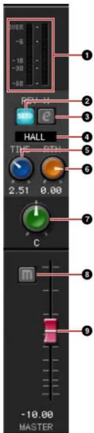
① Level Meter
Indicates the signal level.
② REV-X Send On/Off
Turns the REV-X on (lit) and off (dark).
You can turn this on for one of MIX 1–3.
③ REV-X Edit
Opens (lit) and closes (dark) the "REV-X" (page 23) setup window.
④ REV-X Type
Selects the REV-X type.
Option: Hall, Room, Plate
⑤ REV-X Time
Adjusts the reverb time of the REV-X. This parameter links to Room Size. The adjustable range varies depending on the REV-X type.
REV-X type Range
Hall 0.103 sec - 31.0 sec
Room 0.152 sec - 45.3 sec
Plate 0.176 sec - 52.0 sec
6 REV-X Return Level
Adjusts the return level of the REV-X.
Range: -∞ dB - +6.00 dB
7 Pan
Adjusts the pan.
Range: L16 - C - R16
8 Mute
Turns the mute on (lit) and off (dark).
9 Fader
Adjusts the signal level.
Range: -∞ dB - +6.00 dB
MIX Area
This is the area for selecting the MIX you want to configure.
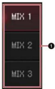
① MIX
Selects the MIX you want to configure.
You can copy the Main window settings of the MIX by dragging and dropping.
Headphone Area
This is the area for selecting the output signal of the headphone. (PHONES 2 only)
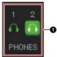
① PHONES On/Off
Turns on (lit) and off (dark) the headphone. You can output the MIX selected in the MIX area to the PHONES by turning this on.
Setup Window
This is the window for configuring the common settings of the device.
![GENERAL SETTINGS CONTROL PANEL INPUT 3/4 LEVEL +4dBu HPF 80Hz INPUT METER SETTING INPUT 1-2 INPUT 3-4 OUTPUT ROUTING S/PDIF OUT MIX 1 L/R OUTPUT (A/B/C) MODE SELECT Alternate OUTPUT LEVEL A (1/2) -∞ [dBi] B (3/4) -∞ [dBi] C (5/6) -∞ [dBi] LINK EDITOR SETTINGS KNOB MOUSE CONTROL Circular SLIDER MOUSE CONTROL Touch steinberg](/content/2026/05/882147/images/6e51e9f22b1a903d8ef1c661e6e3c5efa9a0a3aca004078810fac0f48df8b362.jpg)
① CONTROL PANEL
For Windows, this opens the "Control Panel of the Audio Driver" (page 9). For Mac, this opens the Audio MIDI Setup.
② INPUT 3/4 LEVEL
Selects the input signal level of LINE INPUT 3/4.
Option: +4dBu, -10dBV
③ HPF
Selects the cutoff frequency of the high pass filter.
Option: 120 Hz, 100 Hz, 80 Hz, 60 Hz, 40 Hz
④ Input Meter Setting
Selects the analog input jacks whose input signal levels are indicated on the INPUT meter on the device.
Option Description
INPUT 1-2 Indicates the input signals of MIC/LINE/HI-Z 1/2.
INPUT 3-4 Indicates the input signals of LINE INPUT 3/4.
⑤ S/PDIF OUT
Selects the output signal of the S/PDIF OUT.
6 OUTPUT (A/B/C) MODE SELECT
Selects the function (mode) of the LINE OUTPUT A-C.
There are two modes, Alternate and Independent.
Mode Description
Alternate One of the LINE OUTPUTS A-C selected by the OUTPUT buttons A-C outputs a single MIX signal selected by the SOURCE SELECT button.
Independent The LINE OUTPUTS A–C output each MIX selected by the SOURCE SELECT button at the same time.
⑦ Master Source
Indicates the LINE OUTPUT.
8 Master Level
Indicates the output signal level of the LINE OUTPUT.
⑨ LINK (Independent mode only)
Lets you enable (checkmark) or disable (no checkmark) the function which adjusts the level of all LINE OUTPUT signals by the OUTPUT LEVEL knob on the device at the same time.
For instructions on how to adjust the output signal level with LINK disabled, refer to the "OUTPUT LEVEL knob" (page 8) in the section "Panel Controls and Terminals (Details)."
10 KNOB MOUSE CONTROL
Selects the method of operating the knobs on the dspMixFx UR28M.
Option Description
Circular Drag in a circular motion to increase and decrease the parameter. Drag in a dial clockwise to increase, and counterclockwise to decrease. If you click any point on the knob, the parameter will jump there instantly.
Linear Drag in a linear motion to increase and decrease the parameter. Drag to the upward or rightward to increase, and downward or leftward to decrease. Even if you click any point on the knob, the parameter will not jump there.
⑪ SLIDER MOUSE CONTROL
Selects the method of operating the sliders and faders on the dspMixFx UR28M.
Option Description
Jump Click any point on the slider and fader to increase and decrease the parameter. If you click any point on the slider and fader, the parameter will jump there instantly.
Touch Drag the handle of the slider and fader to increase and decrease the parameter. Even if you click any point on the slider and fader, the parameter will not jump there.
Information Window
This window indicates information about the dspMixFx UR28M and the device.
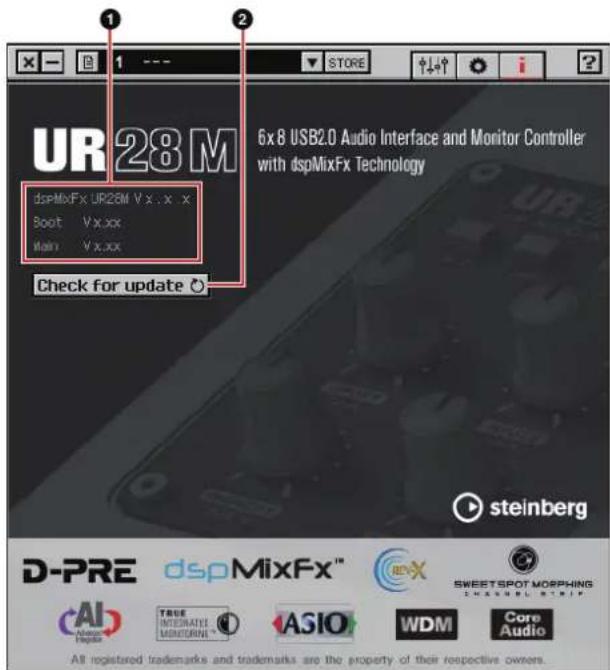
① Version Information
Indicates the version of the firmware and software. The letters "x.x.x" and "x.xx" indicate the version number.
② Check for update
Checks whether or not you have the latest software and firmware version, via the Internet. If a new version is found, follow the on-screen instructions for updating.
Dedicated Windows for Cubase Series
These are the windows for configuring the device settings from Cubase series. The Dedicated Windows for Cubase series allow you to configure the parameters which are configured by the dspMixFx UR28M. from Cubase series. Two types of windows are available: Input Settings and Hardware Setup.
Input Settings Window
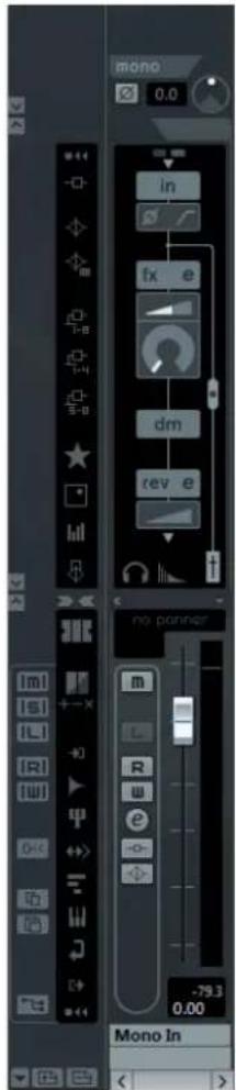
This is the window for configuring the input settings of the device. The signal flow is from top to bottom. The settings on this window are saved to the Cubase project file, except for the +48V indicator.
Hardware Setup Window
This is the window for configuring the general settings of the device. Click the upper tabs to select the window. Only the settings on the Reverb Routing window are saved to the Cubase project file.
Screenshot
Input Settings Window
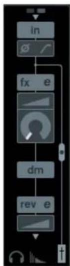
flowchart
graph TD
    A["in"] --> B["fx e"]
    B --> C["dm"]
    C --> D["rev e"]
    D --> E["+"]
Hardware Setup Window
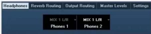
How to Open the Window
Input Settings Window
The Input Settings window appears in the following windows.
- In the Mixer window (Cubase and Cubase Artist only)
• In the VST Input Channel Settings window (Cubase and Cubase Artist only)
• In the VST Audio Channel Settings window (other Cubase series software)
In the Mixer Window (Cubase and Cubase Artist only)
-
[Devices] → [Mixer] to open the Mixer window.
-
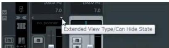
Click "Show Extended View."
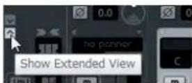
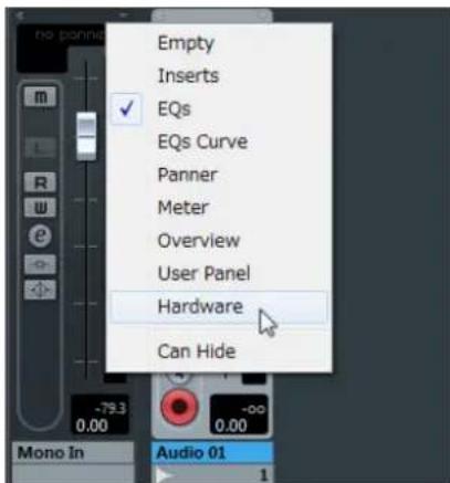
- Click "Extended View Type/Can Hide State" in the input channel.
- Click [Hardware].
The Input Settings window appears in the Mixer window as shown below.
In the VST Input Channel Settings Window (Cubase and Cubase Artist only)
-
[Devices] → [Mixer] to open the mixer.
-
Click "Edit Input Channel Settings" in the input channel.
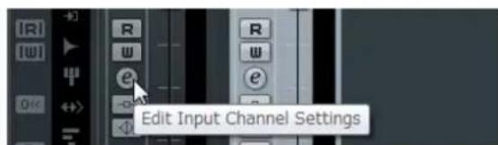
The Input Settings window appears in the VST Input Channel Settings window as shown below.
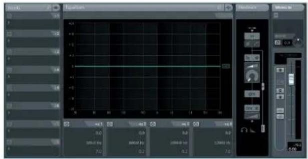
In the VST Audio Channel Settings Window (other Cubase series software)
- Click the audio track from the track list.
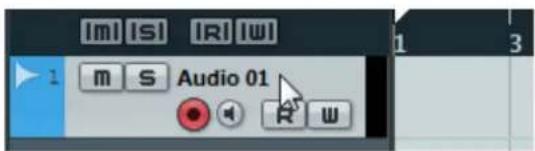
- Click "Edit Channel Settings" in the audio track.
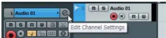
The Input Settings window appears in the VST Audio Channel Settings window as shown below.
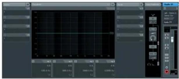
Hardware Setup Window
[Devices] → [Audio Hardware Setup]
Panel Controls
Input Settings Window
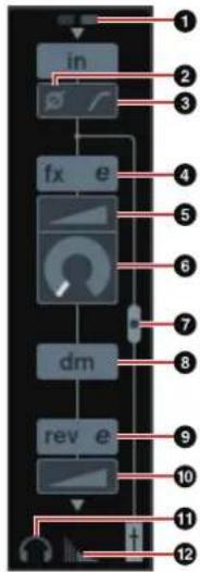
① +48V
Indicates the on/off status of the phantom power function of the device.
② Phase
Turns on (lit) and off (dark) the phase inversion of the signal.
③ High Pass Filter
Turns on (lit) and off (dark) the high pass filter.
To select the cutoff frequency of the high pass filter, use the "Settings Window" (page 20) in the section "Dedicated Windows for Cubase Series."
④ Channel Strip Edit
Opens the "Channel Strip" (page 20) setup window.
⑤ DRIVE
Adjusts the degree to which the compressor is applied. The higher the value, the greater the effect.
Range: 0.00 - 10.00
6 MORPH
Adjusts the Channel Strip Sweet Spot Data. (Refer to the "MORPH" in the section "Channel Strip" on page 20.)
⑦ Channel Strip Insertion Location
Selects the insertion location of the Channel Strip.
| Insertion location | Description |
| Upper (OFF) | Channel Strip is not applied. |
| Middle (MON.FX) | Applies the Channel Strip to only the monitor signal (sent to the device). |
| Lower (INS.FX) | Applies the Channel Strip to both the monitor signal (sent to the device) and the recording signal (sent to the DAW software). |
You can apply four Channel Strips to mono channels, or two Channel Strips to a stereo channel.
⑧ Output Position of the Direct Monitoring Signal
Indicates the position from which the audio signals for monitoring will be output when turning on Direct Monitoring in the device settings on Cubase.
⑨ REV-X Edit
Opens the "REV-X" (page 23) setup window.
10 REV-X Send
Adjusts the signal level which is sent to the REV-X.
Range: -∞ dB - +6.00 dB
⑪ Headphones Edit
Opens the "Headphones Window" (page 19) in the section "Dedicated Windows for Cubase Series."
⑫ Reverb Routing Edit
Opens the “Reverb Routing Window” (page 19) in the section “Dedicated Windows for Cubase Series.”
Hardware Setup Window
Headphones Window
This is the window for selecting the output signal of the PHONES on the device. (PHONES 2 only)
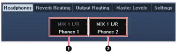
① Phones 1
Indicates the output signal of PHONES 1.
② Phones 2
Selects the output signal of PHONES 2.
Reverb Routing Window
This is the window for configuring the "REV-X" (page 23) settings.
![Headphones Reverb Routing Output Routing Master Levels Settings Hall 2.51 [s] Time Type Destination Return [dB] MIX 1 L/R MIX 2 L/R MIX 3 L/R 3 4 5 6 7](/content/2026/05/882147/images/31d493de5466ad4cf4580ddf475e523ae52c41cae497796c8ce0005bda581f0f.jpg)
① REV-X Edit
Opens the "REV-X" (page 23) setup window.
② REV-X Type
Selects the REV-X type.
Option: Hall, Room, Plate
③ REV-X Time
Adjusts the reverb time of the REV-X. This parameter links to Room Size. The adjustable range varies depending on the REV-X type.
REV-X type Range
Hall 0.103 sec - 31.0 sec
Room 0.152 sec - 45.3 sec
Plate 0.176 sec - 52.0 sec
④ REV-X Send Source Select
Selects the send source signal which is sent to the REV-X. You can select one signal at a time. The checkmark will be on the selected signal.
⑤ REV-X Send Source
Indicates the signal which is sent to the REV-X.
⑥ REV-X Return Level
Indicates the return level of the REV-X.
⑦ REV-X Return Level knob
Adjusts the return level of the selected (highlighted) signal.
Range: -∞ dB - +6.00 dB
Output Routing Window
This is the window for selecting the output signal of the output jacks on the device.
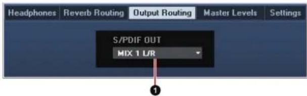
① S/PDIF OUT
Selects the output signal of the S/PDIF OUT.
Master Levels Window
This is the window for configuring the master level of the output jacks on the device.
![Headphones Reverb Routing Output Routing Master Levels Settings OUTPUT (A/B/C) MODE SELECT Alternate A(1/2) B(3/4) C(5/6) Output Level [SB] LINE](/content/2026/05/882147/images/26c40452367349f6642f22fcb5d7e1a4e684ed373bfd69bc1e76f5e10e963f57.jpg)
① OUTPUT (A/B/C) MODE SELECT
Selects the function (mode) of the LINE OUTPUT A-C.
There are two modes, Alternate and Independent.
Mode Description
Alternate One of the LINE OUTPUTS A-C selected by the OUTPUT buttons A-C outputs a single MIX signal selected by the SOURCE SELECT button.
Independent The LINE OUTPUTS A–C output each MIX selected by the SOURCE SELECT button at the same time.
② Master Source
Indicates the LINE OUTPUT.
③ Master Level
Indicates the output signal level of the LINE OUTPUT.
④ LINK (Independent mode only)
Lets you enable (checkmark) or disable (no checkmark) the function which adjusts the level of all LINE OUTPUT signals by the OUTPUT LEVEL knob on the device at the same time.
For instructions on how to adjust the output signal level with LINK disabled, refer to the "OUTPUT LEVEL knob" (page 8) in the section "Panel Controls and Terminals (Details)."
Settings Window
This is the window for configuring the device settings.
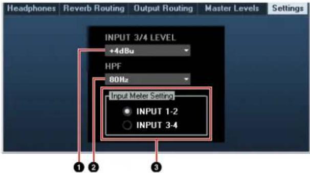
① INPUT 3/4 LEVEL
Selects the input signal level of LINE INPUT 3/4.
Option: +4dBu, -10dBV
② HPF
Selects the cutoff frequency of the high pass filter.
Option: 120 Hz, 100 Hz, 80 Hz, 60 Hz, 40 Hz
③ Input Meter Setting
Selects the analog input jacks whose input signal levels are indicated on the INPUT meter on the device.
Option Description
INPUT 1-2 Indicates the input signals of MIC/LINE/HI-Z 1/2.
INPUT 3-4 Indicates the input signals of LINE INPUT 3/4.
Sweet Spot Morphing Channel Strip (Channel Strip)
This is the window for configuring the Channel Strip settings.
NOTE
- The Channel Strip equipped with the device and the Channel Strip of the VST Plug-in version have the same parameters.
- When using the Channel Strip on Cubase series programs, you can share the settings between the built-in Channel Strip and the Channel Strip of the VST Plug-in version as a preset file.
- When using the built-in Channel Strip on Cubase series programs, turn on the "Direct Monitoring" setting in the program.
- When assigning the Channel Strip of the VST Plug-in version to the effect slot on Cubase series programs, select it from the "Dynamics" category (in the case of the default settings).
Screenshot
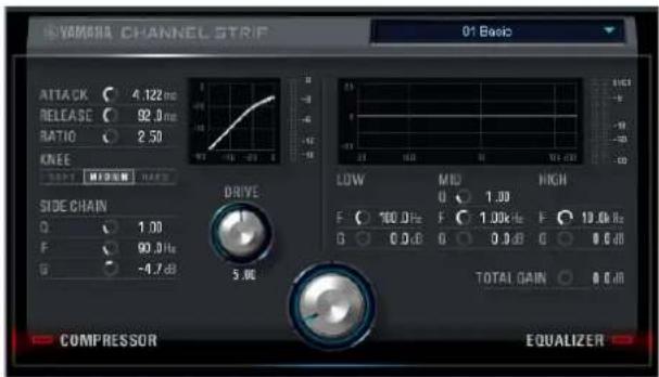
How to Open the Window
From Dedicated Windows for Cubase Series
Click "Channel Strip Edit" (page 18) in the section "Input Settings Window."
From the dspMixFx UR28M
Click "Channel Strip Edit" (page 13) in the section "Channel Area."
Panel Controls
Common to Compressor and Equalizer
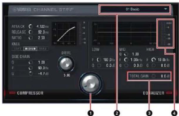
① MORPH
Adjusts the parameter of the Sweet Spot Data.
You can simultaneously adjust the compressor and equalizer settings which are set to five points around this knob by turning this knob. When you set the knob to the middle of adjacent two points, the compressor and equalizer settings will be set to an intermediate value.
② Sweet Spot Data
Selects the Sweet Spot Data (page 28).
③ TOTAL GAIN
Adjusts the total gain of the Channel Strip.
Range: -18.0 dB - +18.0 dB
4 Level Meter
Indicates the output level of the Channel Strip.
Compressor
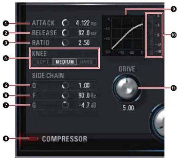
① ATTACK
Adjusts the attack time of the compressor.
Range: 0.092 msec - 80.00 msec
② RELEASE
Adjusts the release time of the compressor.
Range: 9.3 msec - 999.0 msec
③ RATIO
Adjusts the ratio of the compressor.
Range: 1.00 - ∞
4 KNEE
Selects the knee type of the compressor.
Option Description
SOFT Produces the most gradual change.
MEDIUM Middle setting between SOFT and HARD.
HARD Produces the sharpest change.
⑤ SIDE CHAIN Q
Adjusts the band width of the side chain filter (page 28).
Range: 0.50 - 16.00
6 SIDE CHAIN F
Adjusts the center frequency of the side chain filter.
Range: 20.0 Hz - 20.0 kHz
⑦ SIDE CHAIN G
Adjusts the gain of the side chain filter.
Range: -18.0 dB - +18.0 dB
⑧ COMPRESSOR On/Off
Turns the compressor on (lit) and off (dark).
9 Compressor Curve
This graph indicates the approximate compressor response. The vertical axis indicates the output signal level, and the horizontal axis indicates the input signal level.
10 Gain Reduction Meter
Indicates the gain reduction.
⑪ DRIVE
Adjusts the degree to which the compressor is applied. The higher the value, the greater the effect.
Range: 0.00 - 10.00
Equalizer
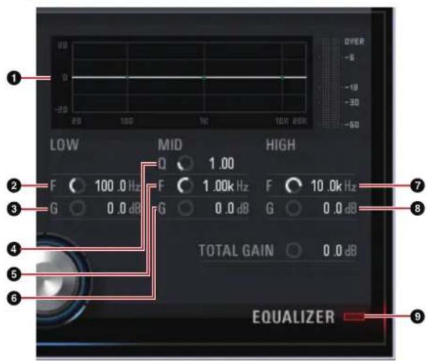
① Equalizer Curve
This graph indicates the characteristics of the 3-band equalizer. The vertical axis indicates the gain, and the horizontal axis indicates the frequency. You can adjust LOW, MID, and HIGH by dragging each handle in the graph.
② LOW F
Adjusts the center frequency of the low band.
Range: 20.0 Hz - 1.00 kHz
③ LOW G
Adjusts the gain of the low band.
Range: -18.0 dB - +18.0 dB
④ MID Q
Adjusts the band width of the middle band.
Range: 0.50 - 16.00
⑤ MID F
Adjusts the center frequency of the middle band.
Range: 20.0 Hz - 20.0 kHz
6 MID G
Adjusts the gain of the middle band.
Range: -18.0 dB - +18.0 dB
7 HIGH F
Adjusts the center frequency of the high band.
Range: 500.0 Hz - 20.0 kHz
8 HIGH G
Adjusts the gain of the high band.
Range: -18.0 dB - +18.0 dB
9 EQUALIZER On/Off
Turns the equalizer on (lit) and off (dark).
REV-X
This is the window for configuring the REV-X settings. Three types of REV-X are available: Hall, Room, and Plate.
NOTE
- The REV-X equipped with the device and REV-X of the VST Plug-in version have the same parameters. However, the "OUTPUT" and "MIX" parameters are only available in the VST Plug-in version.
- When using the REV-X on Cubase series programs, you can share the settings between the built-in REV-X and the REV-X of the VST Plug-in version as a preset file.
- When using the built-in REV-X on Cubase series programs, turn on the "Direct Monitoring" setting in the program.
- When assigning the REV-X of the VST Plug-in version to the effect slot on Cubase series programs, select it from the "Reverb" category (in the case of the default settings).
- The built-in REV-X is equipped with an "FX Bus" which is used for sending the signal from DAW software to the REV-X. For example, to send the recorded audio data to the REV-X, you can check the sound with the REV-X, which is used for monitoring during the recording.
Screenshot
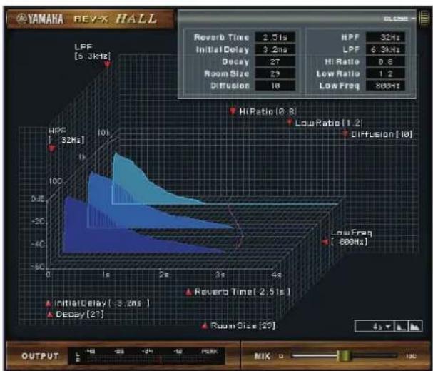
line
| Metric | Value | | ---------------- | ----- | | LFP | 5.3kHz | | Hi/Freq | 800Hz | | Low Freq | 800Hz | | Diffusion | 101 | | Low Ratio | 1.2 | | Hi Ratio | 0.6 | | Diffusion | 101 | | Initial Delay | 3.2ns | | Decay | 27 | | Room Size | 29 | | Diffusion | 19 | | Reverb Time | 2.51s | | Output | - | | MIX | 100 |How to Open the Window
From Dedicated Windows for Cubase Series
- Click "REV-X Edit" (page 19) in the section "Input Settings Window."
- Click "REV-X Edit" (page 19) in the section "Reverb Routing Window."
From the dspMixFx UR28M
Click "REV-X Edit" (page 14) in the section "Master Area."
Panel Controls
![YAMAHA REV-X HALL LPF [5.3kHz] HPF [32Hz] 10k 0.4k 60 0 18 25 35 45 REVER TINER Revers Time 2.51s NPF 32Hz Initial Delay 3.2ns LPF 6.3kHz Decay 27 HI Ratio 0.8 Room Size 29 Low Ratio 1.2 Diffusion 18 Low Freq 900Hz Hi Ratio [0.9] Low Freq [1.2] Diffusion [13] Low Freq [900Hz] Initial Delay [3.2ns] Decay [27] Room Size [29] OUTPUT -18 -25 -24 -12 PERK MIX 3 14 15 16 17](/content/2026/05/882147/images/f0f5b66c91a24db2f365e3cb64c85bae9a3b904dbebd86a935dd38fa07b9c35c.jpg)
NOTE
This section uses the Hall type of REV-X as an example.
① Reverb Time
Adjusts the reverb time. This parameter links to Room Size. The adjustable range varies depending on the REV-X type.
REV-X type Range
Hall 0.103 sec - 31.0 sec
Room 0.152 sec - 45.3 sec
Plate 0.176 sec - 52.0 sec
② Initial Delay
Adjusts the time that elapses between the direct, original sound and the initial reflections that follow it.
Range: 0.1 msec - 200.0 msec
③ Decay
Adjusts the characteristic of the envelope from the moment the reverberation starts to the moment it attenuates and stops.
Range: 0 - 63
4 Room Size
Adjusts the size of the simulated room. This parameter links to Reverb Time.
Range: 0 - 31
⑤ Diffusion
Adjusts the spread of the reverberation.
Range: 0 - 10
6 HPF
Adjusts the cutoff frequency of the high pass filter.
Range: 20 Hz – 8.0 kHz
⑦ LPF
Adjusts the cutoff frequency of the low pass filter.
Range: 1.0 kHz – 20.0 kHz
8 Hi Ratio
Adjusts the duration of reverberation in the high frequency range by using a ratio relative to the Reverb Time. When you set this parameter to 1, the actual specified Reverb Time is fully applied to the sound. The lower the value, the shorter the duration of reverberation in the high frequency range.
Range: 0.1 - 1.0
9 Low Ratio
Adjusts the duration of reverberation in the low frequency range by using a ratio relative to the Reverb Time. When you set this parameter to 1, the actual specified Reverb Time is fully applied to the sound. The lower the value, the shorter the duration of reverberation in the low frequency range.
Range: 0.1 - 1.4
10 Low Freq
Adjusts the frequency of the Low Ratio.
Range: 22.0 Hz – 18.0 kHz
⑪ OPEN/CLOSE
Opens and closes the window which adjusts the reverb settings.
12 Graph
Indicates the characteristics of reverberation. The vertical axis indicates the signal level, the horizontal axis indicates the time, and the Z-axis indicates the frequency. You can adjust the characteristics of reverberation by dragging the handles in the graph.
13 OUTPUT (VST Plug-in version only)
Indicates the output level of the REV-X.
14 MIX (VST Plug-in version only)
Adjusts the output level balance between the original sound and effect sound.
Range: 0% - 100%
15 Time Axis Setting
Select the display range of the time (horizontal axis) on the graph.
Display range: 500 msec – 50 sec
16 Zoom Out
Zooms out the display range of the time (horizontal axis) on the graph.
17 Zoom In
Zooms in the display range of the time (horizontal axis) on the graph.
TIPS
- You can reset some parameters to the default value by holding the [Ctrl]/[command] key while you click on the knobs, sliders, and faders.
- You can adjust the parameters more finely by holding the [SHIFT] key while you drag on the knobs, sliders, and faders.
Usage Examples
Introduction
This section introduces some usage examples of the device. It is assumed that the audio driver settings on the DAW software have been properly configured according to the "Basic Operation" section in the included Getting Started manual. If you have not configured them yet, refer to the section "Basic Operation" to complete the configuration.
Recording with the Channel Strip and REV-X
This section shows how to record a vocal to DAW software using the built-in Channel Strip and REV-X on the device. When using Cubase series programs, it is handy to use the project template. These project templates include the settings of the Channel Strip and REV-X. You can start recording instantly by opening the project template. When using programs other than the Cubase series, use the dspMixFx UR28M.
Connection Example
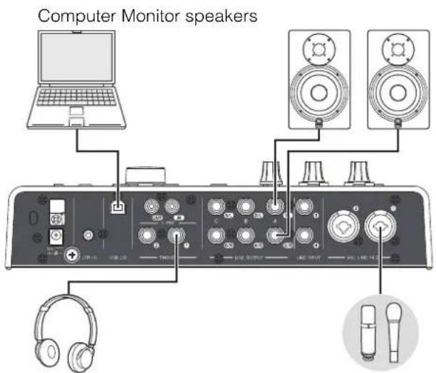
Headphones Microphone
Operation
Cubase Series Programs
1. Launch the Cubase series DAW.
The Project Assistant window appears.
- Select the project template "Steinberg UR28M Vocal-Inst Recording 1" in "Recording" on the Project Assistant window, then click [Create].
3. Turn on Direct Monitoring as follows.
[Devices] → [Device Setup] → [Yamaha Steinberg USB ASIO] (Windows) or [Steinberg UR28M] (Mac) → enter checkmark to "Direct Monitoring" → [OK]
4. Confirm that the "Record Enable" and "Monitor" indicators are turned on (lit) for the audio track.
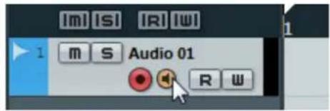
5. While singing into the microphone, adjust the input signal level of the microphone by the INPUT GAIN knob on the device.
Adjust the input signal level so that the red lamp in the INPUT meter does not light.
6. While singing into the microphone, adjust the output signal level of the headphones by the PHONES knob on the device.
7. Set the Channel Strip settings and REV-X settings on the Input Settings window.
Select the Channel Strip Insertion Location depending on the desired insert point. The default setting is "Lower" (applied to both the monitor signal and the recording signal). For details on the Insertion Location, refer to the "Channel Strip Insertion Location" (page 19) in the section "Dedicated Windows for Cubase Series."
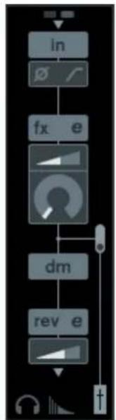
flowchart
graph TD
    A["in"] --> B["∅"]
    B --> C["fx e"]
    C --> D["dm"]
    D --> E["rev e"]
    E --> F["+"]
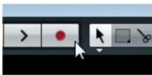
- Click "Record" to start the recording.
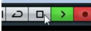
- After finishing the recording, click "Stop" to stop it.
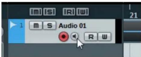
- Turn "Monitor" off (dark) for the audio track.
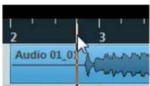
- Click the Ruler to move the project cursor to the desired point for starting playback.
- Click "Play" to check the recorded sound.
When listening to the sound over monitor speakers, adjust the output signal level by the OUTPUT LEVEL knob on the device.
Operation is now completed.
Programs Other Than Cubase Series
-
Launch your DAW software.
-
Open the dspMixFx UR28M.
For instructions on how to open the dspMixFx UR28M, refer to the section "How to Open the Window" (page 11).
- Adjust the input signal level of the microphone by the INPUT GAIN knob on the device.
Adjust the input signal level so that the red lamp in the INPUT meter does not light.
-
Adjust the output signal level of the headphone by the PHONES knob on the device.
-
Set the Channel Strip settings and REV-X settings on the dspMixFx UR28M.

-
Start recording on your DAW software.
-
After finishing recording, stop it.
-
Playback the newly recorded sound to check it.
Operation is now completed.
Controlling the Monitor Sound
This section shows how to control the monitor sound by using the buttons and knobs on the device.
Connection Example
Monitor speakers Monitor speakers
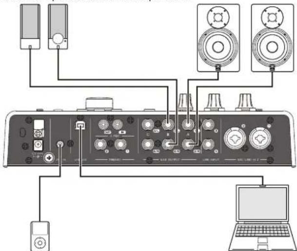
Portable audio player Computer
Operation
-
Play back some music with your DAW software or music player.
-
Control the monitor sound by using the following buttons and knobs.
OUTPUT button A-C OUTPUT LEVEL knob MUTE button MONO MIX button DIM button
For details on the buttons and knobs, refer to the "Front Panel" (page 6) in the section "Panel Control and Terminals (Details)."
The procedures are now complete.
Using the Device Without a Computer
This section shows how to use the device without a computer, allowing you to use it as a standalone mixer or A/D - D/A converter. You can save the DSP mixer and DSP effect settings configured by the dspMixFx UR28M to the device. These settings are maintained even if you turn off the power of the device.
Connection Example
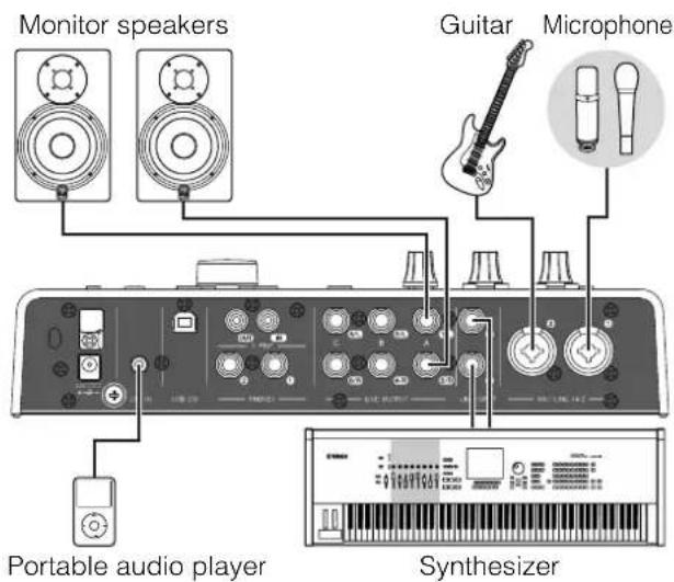
Procedures
-
Connect the device to a computer with a USB cable.
-
Turn on the device.
-
Open the dspMixFx UR28M.
For instructions on opening the dspMixFx UR28M, refer to the "How to Open the Window" (page 11) in the section "dspMixFx UR28M."
-
Configure the DSP mixer and DSP effect settings.
-
When you make the settings, click [X] on the upper left of the window to close the dspMixFx UR28M.
The settings of the dspMixFx UR28M are saved to the device.
The operation is now complete.
Appendix
Glossary
MIX
MIX refers to the stereo output signals which flow in the device. The input signals to the device flow to each MIX. You can assign any MIX to any analog output jack or any digital output jack.
VST Plug-in
VST (Virtual Studio Technology) is a technology developed by Steinberg which allows the integration of virtual effect processors and instruments into your digital audio environment. VST Plug-ins are instrument- and effect-based software of VST format. When you install a VST Plug-in to your computer, it will work on any DAW software compatible with VST Plug-ins, such as Cubase series.
DAW (Digital Audio Workstation)
DAW is an integrative system of music production, which lets you record and edit digital audio data. DAW software programs are applications which allow you to build such comprehensive systems on a computer.
Word Clock
Word clock synchronizes the process timing of audio signals when transferring digital audio data between multiple devices. Normally, one device transmits a reference word clock signal, and the other devices receive this word clock signal and synchronize to it. If the word clock signal is not transferred correctly, click noise may occur or recording may not be successful, even if the sample rates of the various devices are set to the same value.
Buffer Size
Buffer size refers to the amount of memory used to temporarily hold data during playback and recording. It is recommended to adjust the buffer size depending on the situation. Normally, a higher buffer size reduces load to the computer CPU but produces latency (time lag). Smaller buffer sizes reduce latency but produce greater load to the computer CPU. This high load to the computer CPU may result in noise or the sound cutting off.
Scene
A Scene is stored data which maintains the settings on the Main window of dspMixFx UR28M. You can recall the stored Scene in dspMixFx UR28M, and up to 20 Scenes can be stored.
Settings file of the dspMixFx UR28M
The settings file of the dspMixFx UR28M is a data file including up to 20 scenes which can be saved to your computer. You can load the dspMixFx UR28M settings file to the dspMixFx UR28M.
Sweet Spot Data
Sweet Spot Data are preset settings data of the Sweet Spot Morphing Channel Strip created by top-class engineers. This data includes the settings for the compressor and equalizer which are saved to each five points around the MORPH knob.
Side Chain Filter
The side chain filter is a peaking filter which adjusts the frequency range to which the compressor is applied. It features Q (band width), F (center frequency), and G (gain) parameters. For example, if the compressor reduces the audio signal level excessively because only the specified frequency of the audio signal is at a high level (and other frequencies are lower), you can selectively lower the level of the specified frequency by using this peaking filter. This will prevent the compressor from excessive level reduction.
Contents of the Getting Started Section
PRECAUTIONS
Introduction
A Message from the Development Team Included Accessories How to Read the Manual
Panel Controls and Terminals
Rear Panel Front Panel
Setup
- Setting up the Power Supply
- Installing Cubase AI
- Installing TOOLS for UR28M
- Downloading the Licenses (Activation)
Basic Operations
Introduction Connection Example Configuring Audio Driver Settings on the DAW Software
Troubleshooting
Appendix
Contents of the Operation Manual Uninstalling TOOLS for UR28M Specifications
Signal Flow
The following chart indicates the signal flow in the device.
NOTE
- The controllers on the device, such as the HI-Z switch, INPUT GAIN knob, and OUTPUT LEVEL knob, are not included in this chart.
- To configure each parameter, use the "dspMixFx UR28M" (page 10) or "Dedicated Windows for Cubase Series" (page 16).
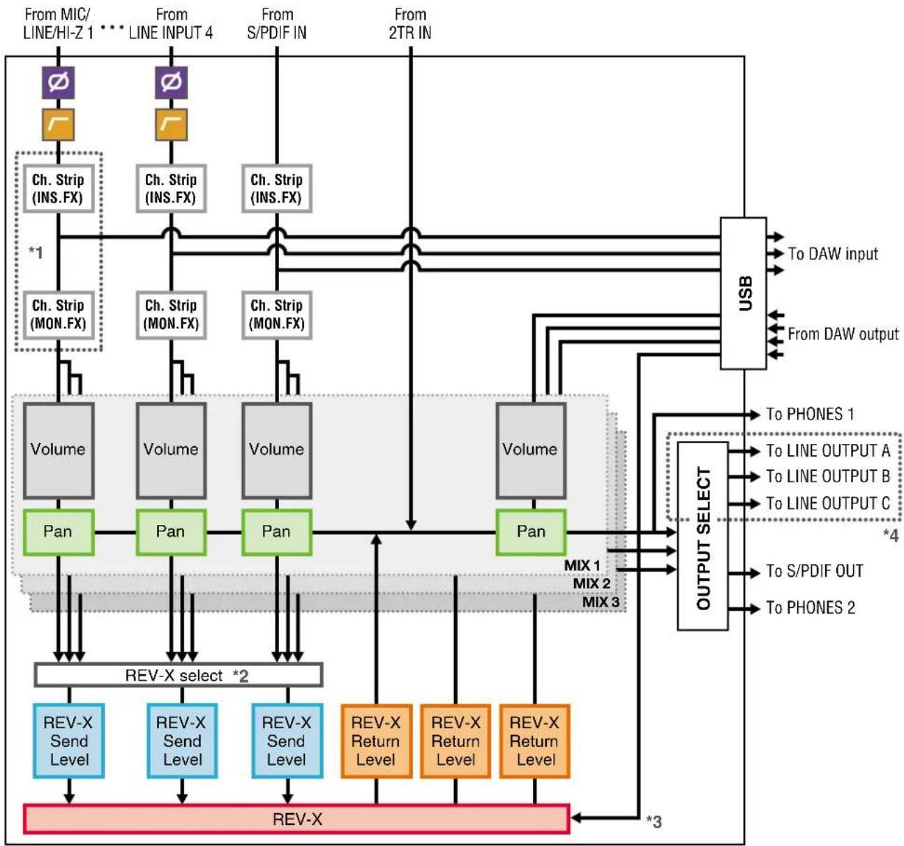
flowchart
graph TD
    A["From MIC/LINE/HI-Z 1"] --> B["Ch. Strip (INS.FX)"]
    C["From LINE INPUT 4"] --> D["Ch. Strip (INS.FX)"]
    E["From S/PDIF IN"] --> F["Ch. Strip (INS.FX)"]
    G["From 2TR IN"] --> H["Ch. Strip (MON.FX)"]
    B --> I["Volume"]
    D --> J["Volume"]
    F --> K["Volume"]
    H --> L["Volume"]
    I --> M["Pan"]
    J --> N["Pan"]
    K --> O["Pan"]
    L --> P["Pan"]
    M --> Q["REV-X Select *2"]
    N --> Q
    O --> Q
    P --> R["REV-X Send Level"]
    Q --> S["REV-X Send Level"]
    R --> T["REV-X Send Level"]
    S --> U["REV-X Send Level"]
    T --> V["REV-X"]
    U --> W["REV-X"]
    V --> X["REV-X"]
    W --> Y["REV-X"]
    X --> Z["REV-X"]
    Y --> AA["REV-X"]
    Z --> AB["REV-X"]
    style A fill:#f9f,stroke:#333
    style C fill:#f9f,stroke:#333
    style E fill:#f9f,stroke:#333
    style G fill:#f9f,stroke:#333
    style G fill:#f9f,stroke:#333
    style G fill:#f9f,stroke:#333
    style H fill:#f9f,stroke:#333
    style I fill:#ccf,stroke:#333
    style J fill:#ccf,stroke:#333
    style K fill:#ccf,stroke:#333
    style L fill:#ccf,stroke:#333
    style M fill:#ccf,stroke:#333
    style N fill:#ccf,stroke:#333
    style O fill:#ccf,stroke:#333
    style P fill:#ccf,stroke:#333
    style Q fill:#ccf,stroke:#333
    style R fill:#ccf,stroke:#333
    style S fill:#ccf,stroke:#333
    style T fill:#ccf,stroke:#333
    style U fill:#ccf,stroke:#333
    style V fill:#ccf,stroke:#333
    style W fill:#ccf,stroke:#333
    style X fill:#ccf,stroke:#333
    style Y fill:#ccf,stroke:#333
    style Z fill:#ccf,stroke:#333
*1The following chart indicates the Ch.Strip (Channel Strip) insertion location.
Upper (INS.FX)
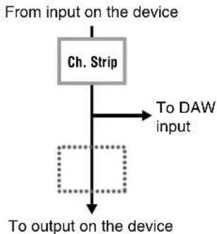
flowchart
graph TD
    A["From input on the device"] --> B["Ch. Strip"]
    B --> C["To DAW input"]
    C --> D["To output on the device"]
    D --> E["Feedback loop"]
Lower (MON.FX)
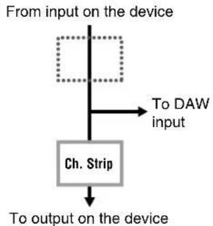
flowchart
graph TD
    A["From input on the device"] --> B["To DAW input"]
    B --> C["Ch. Strip"]
    C --> D["To output on the device"]
Not applied (OFF)
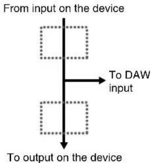
flowchart
graph TD
    A["From input on the device"] --> B["To DAW input"]
    B --> C["To output on the device"]
You can apply four Channel Strips to mono channels, or two Channel Strips to a stereo channel.
*2 One of the MIX 1–3 signals can be sent to the REV-X.
*3 The built-in REV-X is equipped with an "FX Bus" which is used for sending the signal from DAW software to the REV-X. For example, to send the recorded audio data to the REV-X, you can check the sound with the REV-X, which is used for monitoring during the recording.
*4 To select the output signal for LINE OUTPUT A-C, use the buttons on the device. The following charts indicate the structures.
Alternate mode
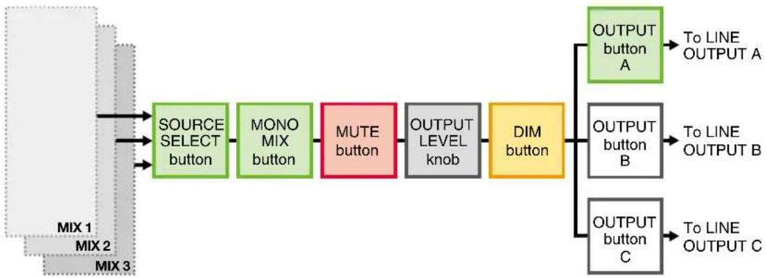
flowchart
graph LR
    A["MIX 1"] --> B["SOURCE SELECT button"]
    C["MIX 2"] --> B
    D["MIX 3"] --> B
    B --> E["MONO MIX button"]
    E --> F["MUTE button"]
    F --> G["OUTPUT LEVEL knob"]
    G --> H["DIM button"]
    H --> I["OUTPUT button A"]
    H --> J["OUTPUT button B"]
    H --> K["OUTPUT button C"]
    I --> L["To LINE OUTPUT A"]
    J --> M["To LINE OUTPUT B"]
    K --> N["To LINE OUTPUT C"]
Independent mode
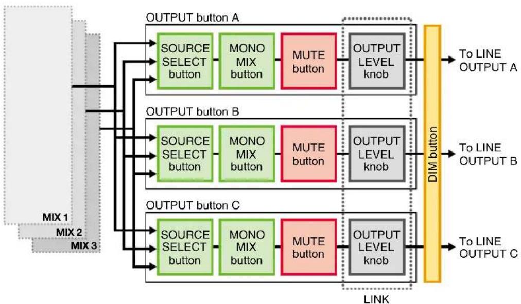
flowchart
graph TD
    MIX1["MIX 1"] --> OUTPUTA["OUTPUT button A"]
    MIX2["MIX 2"] --> OUTPUTA
    MIX3["MIX 3"] --> OUTPUTA
    OUTPUTA --> SOURCE1["SOURCE SELECT button"]
    SOURCE1 --> MONOMIX1["MONO MIX button"]
    MONOMIX1 --> MUTE1["MUTE button"]
    MUTE1 --> OUTPUTLevelKnob["OUTPUT LEVEL knob"]
    OUTPUTLevelKnob --> DIMButton["DIM button"]
    SOURCE1 --> SOURCE2["SOURCE SELECT button"]
    SOURCE2 --> MONOMIX2["MONO MIX button"]
    MONOMIX2 --> MUTE2["MUTE button"]
    MUTE2 --> OUTPUTLevelKnob
    OUTPUTLevelKnob --> DIMButton
    SOURCE2 --> SOURCE3["SOURCE SELECT button"]
    SOURCE3 --> MONOMIX3["MONO MIX button"]
    MONOMIX3 --> MUTE3["MUTE button"]
    MUTE3 --> OUTPUTLevelKnob
    SOURCE3 --> SOURCE4["SOURCE SELECT button"]
    SOURCE4 --> MONOMIX4["MONO MIX button"]
    MONOMIX4 --> MUTE4["MUTE button"]
    MUTE4 --> OUTPUTLevelKnob
    OUTPUTLevelKnob --> DIMButton
    SOURCE4 --> SOURCE5["SOURCE SELECT button"]
    SOURCE5 --> MONOMIX5["MONO MIX button"]
    MONOMIX5 --> MUTE5["MUTE button"]
    MUTE5 --> OUTPUTLevelKnob
    SOURCE5 --> SOURCE6["SOURCE SELECT button"]
    SOURCE6 --> MONOMIX6["MONO MIX button"]
    MONOMIX6 --> MUTE6["MUTE button"]
    MUTE6 --> OUTPUTLevelKnob
    SOURCE6 --> SOURCE7["SOURCE SELECT button"]
    SOURCE7 --> MONOMIX7["MONO MIX button"]
    MONOMIX7 --> MUTE7["MUTE button"]
    MUTE7 --> OUTPUTLevelKnob
    SOURCE7 --> SOURCE8["SOURCE SELECT button"]
    SOURCE8 --> MONOMIX8["MONO MIX button"]
    MONOMIX8 --> MUTE8["MUTE button"]
    MUTE8 --> OUTPUTLevelKnob
    SOURCE8 --> SOURCE9["SOURCE SELECT button"]
    SOURCE9 --> MONOMIX9["MONO MIX button"]
    MONOMIX9 --> MUTE9["MUTE button"]
    MUTE9 --> OUTPUTLevelKnob
    SOURCE9 --> SOURCE10["SOURCE SELECT button"]
    SOURCE10 --> MONOMIX10["MONO MIX button"]
    MONOMIX10 --> MUTE10["MUTE button"]
    MUTE10 --> OUTPUTLevelKnob
    SOURCE10 --> SOURCE11["SOURCE SELECT button"]
    SOURCE11 --> MONOMIX11["MONO MIX button"]
    MONOMIX11 --> MUTE11["MUTE button"]
    MUTE11 --> OUTPUTLevelKnob
    SOURCE11 --> SOURCE12["SOURCE SELECT button"]
    SOURCE12 --> MONOMIX12["MONO MIX button"]
    MONOMIX12 --> MUTE12["MUTE button"]
    MUTE12 --> OUTPUTLevelKnob
    SOURCE12 --> SOURCE13["SOURCE SELECT button"]
    SOURCE13 --> MONOMIX13["MONO MIX button"]
    MONOMIX13 --> MUTE13["MUTE button"]
    MUTE13 --> OUTPUTLevelKnob
    SOURCE13 --> SOURCE14["SOURCE SELECT button"]
    SOURCE14 --> MONOMIX14["MONO MIX button"]
    MONOMIX14 --> MUTE14["MUTE button"]
    MUTE14 --> OUTPUTLevelKnob
Block Diagrams
UR28M
4 Analog In/6 Analog Out, 2 Digital In/Out, 10 DAW In/6 DAW Out, 6+2 Bus
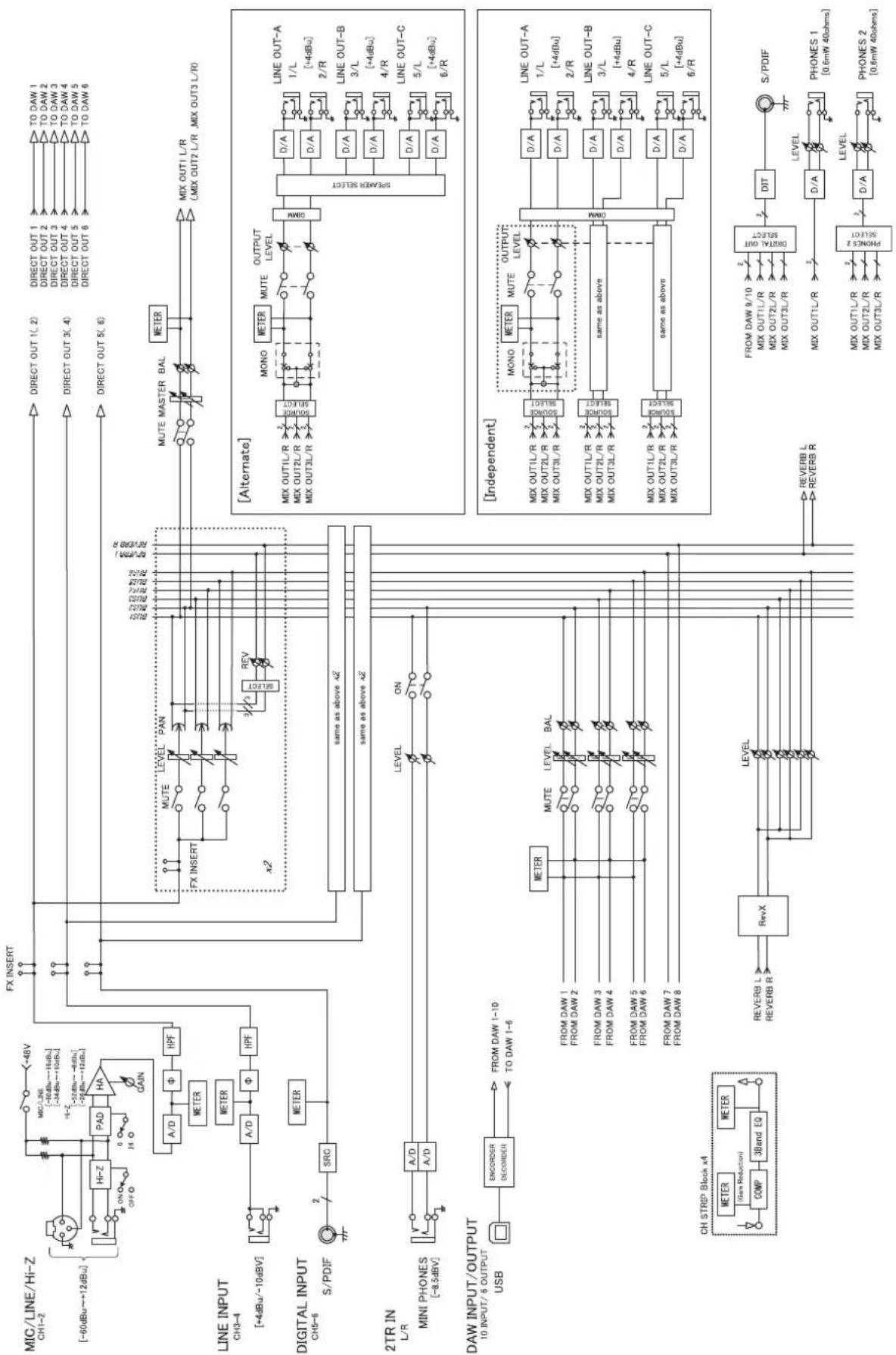
flowchart
graph TD
    subgraph CH1-2
        A["CH1-2 (-60dBu~+12dBu)"] --> B["HI-Z"]
        B --> C["Pad"]
        C --> D["HA"]
        D --> E["GAIN"]
        E --> F["A/D"]
        F --> G["Φ"]
        G --> H["HPF"]
        H --> I["METER"]
        I --> J["LINE INPUT CH13-4 (+4dBu/-10dBV)"]
        J --> K["A/D"]
        K --> L["Φ"]
        L --> M["HPF"]
        M --> N["METER"]
        N --> O["S/PDIF"]
        O --> P["SRC"]
    end

    subgraph Digital INPUT
        Q["CH13-6 S/PDIF"] --> R["2"]
        R --> S["SRC"]
    end

    subgraph DAC
        T["FX INSERT"] --> U["FX INSERT"]
        V["MUTE LEVEL PAN"] --> W["REV"]
        X["MUTE MASTER BAL"] --> Y["METER"]
        Z["×2"] --> AA["×2"]

        AB["same as above 42"] --> AC["same as above 42"]

        AD["LEVEL ON"] --> AE["LEVEL ON"]

        AF["AL/AL/AL/AL"] --> AG["AL/AL/AL/AL/AL/AL/AL/AL/AL/AL/AL/AL/AL/AL/AL/AL/AL/AL/AL/AL/AL/AL/AL/AL/AL/AL/AL/AL/AL/AL/AL/AL/AL/AL/AL/AL/AL/AL/AL/AL/AL/AL/AL/AL/AL/AL/AL/AL/AL/AL/AL /MIX OUT1 L/R (MIX OUT2 L/R) /MIX OUT3 L/R"]

    subgraph Alternate
        AD1["MIX OUT1L/R"] --> AD2["MIX OUT2L/R"] --> AD3["MIX OUT3L/R"]
        AD1 --> AD4["D/A"] --> AD5["D/A"] --> AD6["D/A"] --> AD7["D/A"] --> AD8["D/A"] --> AD9["D/A"] --> AD10["L/L (1+4dBu)"] --> AD11["L/L (1+4dBu)"] --> AD12["L/L (1+4dBu)"] --> AD13["L/L (1+4dBu)"] --> AD14["L/L (1+4dBu)"] --> AD15["L/L (1+4dBu)"] --> AD16["L/L (1+4dBu)"] --> AD17["L/L (1+4dBu)"] --> AD18["L/L (1+4dBu)"] --> AD19["L/L (1+4dBu)"] --> AD20["L/L (1+4dBu)"] --> AD21["L/L (1+4dBu)"] --> AD22["L/L (1+4dBu)"] --> AD23["L/L (1+4dBu)"] --> AD24["L/L (1+4dBu)"] --> AD25["L/L (1+4dBu)"] --> AD26["L/L (1+4dBu)"] --> AD27["L/L (1+4dBu)"] --> AD28["L/L (1+4dBu)"] --> AD29["L/L (1+4dBu)"] --> AD30["L/L (1+4dBu)"] --> AD31["L/L (1+4dBu)"] --> AD32["L/L (1+4dBu)"] --> AD33["L/L (1+4dBu)"] --> AD34["L/L (1+4dBu)"] --> AD35["L/L (1+4dBu)"] --> AD36["L/L (1+4dBu)"] --> AD37["L/L (1+4dBu)"] --> AD38["L/L (1+4dBu)"] --> AD39["L/L (1+4dBu)"] --> AD40["L/L (1+4dBu)"] --> AD41["L/L (1+4dBu)"] --> AD42["L/L (1+4dBu)"] --> AD43["L/L (1+4dBu)"] --> AD44["L/L (1+4dBu)"] --> AD45["L/L (1+4dBu)"] --> AD46["L/L (1+4dBu)"] --> AD47["L/L (1+4dBu)"] --> AD48["L/L (1+4dBu)"] --> AD49["L/L (1+4dBu)"] --> AD50["L/L (1+4dBu)"] --> AD51["L/L (1+4dBu)"] --> AD52["L/L (1+4dBu)"] --> AD53["L/L (1+4dBu)"] --> AD54["L/L (1+4dBu)"] --> AD55["L/L (1+4dBu)"] --> AD56["L/L (1+4dBu)"] --> AD57["L/L (1+4dBu)"] --> AD58["L/L (1+4dBu)"] --> AD59["L/L (1+4dBu)"] --> AD60["L/L (1+4dBu)"]
    end

    subgraph Independent
        AF["MIX OUT1L/R"] --> AF1["MIX OUT2L/R"] --> AF2["MIX OUT3L/R"]
        AF1 --> AF3["MIX OUT3L/R"]
        AF2 --> AF4["MIX OUT3L/R"]
        AF3 --> AF5["MIX OUT3L/R"]
        AF4 --> AF6["MIX OUT3L/R"]
        AF5 --> AF6
        AF6 --> AF7["MIX OUT3L/R"]
        AF7 --> AF8["MIX OUT3L/R"]
        AF8 --> AF9["MIX OUT3L/R"]
        AF9 --> AF10["MIX OUT3L/R"]
        AF10 --> AF10
        AF10 --> AF11["MIX OUT3L/R"]
        AF11 --> AF12["MIX OUT3L/R"]
        AF12 --> AF12
        AF12 --> AF13["MIX OUT3L/R"]
        AF13 --> AF13
        AF13 --> AF14["MIX OUT3L/R"]
        AF14 --> AF14
        AF14 --> AF15["MIX OUT3L/R"]
        AF15 --> AF15
        AF15 --> AF16["MIX OUT3L/R"]
        AF16 --> AF16
        AF16 --> AF17["MIX OUT3L/R"]
        AF17 --> AF17
        AF17 --> AF18["MIX OUT3L/R"]
        AF18 --> AF18
        AF18 --> AF19["MIX OUT3L/R"]
        AF19 --> AF19
        AF19 --> AF20["MIX OUT3L/R"]
        AF20 --> AF20
        AF20 --> AF21["MIX OUT3L/R"]
        AF21 --> AF21
        AF22["MIX OUT3L/R"]
        AF22 --> AF22
        AF23["MIX OUT3L/R"]
        AF23 --> AF23
        AF24["MIX OUT3L/R"]
        AF24 --> AF24
        AF25["MIX OUT3L/R"]
        AF25 --> AF25
        AF26["MIX OUT3L/R"]
        AF26 --> AF26
        AF27["MIX OUT3L/R"]
        AF27 --> AF27
        AF28["MIX OUT3L/R"]
        AF28 --> AF28
        AF29["MIX OUT3L/R"]
        AF29 --> AF29
        AF30["MIX OUT3L/R"]
        AF30 --> AF30
        AF31["MIX OUT3L/R"]
        AF31 --> AF31
        AF32["MIX OUT3L/R"]
        AF32 --> AF32
        AF33["MIX OUT3L/R"]
        AF33 --> AF33
        AF34["MIX OUT3L/R"]
        AF34 --> AF34
        AF35["MIX OUT3L/R"]
        AF35 --> AF35
        AF36["MIX OUT3L/R"]
        AF36 --> AF36
        AF37["MIX OUT3L/R"]
        AF37 --> AF37
        AF38["MIX OUT3L/R"]
        AF38 --> AF38
        AF39["MIX OUT3L/R"]
        AF39 --> AF39
        AF40["MIX OUT3L/R"]
        AF40 --> AF40
        AF41["MIX OUT3L/R"]
        AF41 --> AF41
        AF42["MIX OUT3L/R"]
        AF42 --> AF42
        AF43["MIX OUT3L/R"]
        AF43 --> AF43
        AF44["MIX OUT3L/R"]
        AF44 --> AF44
        AF45["MIX OUT3L/R"]
        AF45 --> AF45
        AF46["MIX OUT3L/R"]
        AF46 --> AF46
        AF47["MIX OUT3L/R"]
        AF47 --> AF47
        AF48["MIX OUT3L/R"]
        AF48 --> AF48
        AF49["MIX OUT3L/R"]
        AF49 --> AF49
        AF50["MIX OUT3L/R"]
        AF50 --> AF50
        AF51["MIX OUT3L/R"]
        AF51 --> AF51
        AF52["MIX OUT3L/R"]
        AF52 --> AF52
    end

    subgraph CH STRIP Block x4
    AH["CH STRIP Block x4"] --> AI["COMP 3Band EQ"] & AJ["COMP 3Band EQ"] & AK["COMP 3Band EQ"] & AL["COMP 3Band EQ"] & AM["COMP 3Band EQ"] & AN["COMP 3Band EQ"] & AO["COMP 3Band EQ"] & AP["COMP 3Band EQ"] & AQ["COMP 3Band EQ"] & AR["COMP 3Band EQ"] & AS["COMP 3Band EQ"] & AT["COMP 3Band EQ"] & AU["COMP 3Band EQ"] & AV["COMP 3Band EQ"] & AW["COMP 3Band EQ"] & AX["COMP 3Band EQ"] & AY["COMP 3Band EQ"] & AZ["COMP 3Band EQ"] & BA["COMP 3Band EQ"] & BB["COMP 3Band EQ"] & BC["COMP 3Band EQ"] & CD["COMP 3Band EQ"] & CE["COMP 3Band EQ"] & CF["COMP 3Band EQ"] & CG["COMP 3Band EQ"] & DH["COMP 3Band EQ"] & DI["COMP 3Band EQ"] & DJ["COMP 3Band EQ"] & DK["COMP 3Band EQ"] & DL["COMP 3Band EQ"] & DV["COMP 3Band EQ"] & DW["COMP 3Band EQ"] & DX["COMP 3Band EQ"] & DXB["COMP 3Band EQ"] & DXC["COMP 3Band EQ"] & DXD["COMP 3Band EQ"] & DXE["COMP 3Band EQ"] & DXF["COMP 3Band EQ"] & DXG["COMP 3Band EQ"] & DXH["COMP 3Band EQ"] & DXI["COMP 3Band EQ"] & DXJ["COMP 3Band EQ"] & DXK["COMP 3Band EQ"] & DXIb["DIT"] & DXJ["DIT"] & DXJ["DIT"] & DXJ["DIT"] & DXJ["DIT"] & DXJ["DIT"] & DXJ["DIT"] & DXJ["DIT"] & DXJ["DIT"] & DXJ["DIT"] & DXJ["DIT"] & DXJ["DIT"] & DXJ["DIT"] & DXJ["DIT"] & DXJ["DIT"] & DXJ["DIT"] & DXJ["DIT"] & DXJ["DIT"] &
DXJ["DIT"] & DXJ["DIT"] & DXJ["DIT"] & DXJ["DIT"] & DXJ["DIT"] & DXJ["DIT"] & DXJ["DIT"] & DXJ["DIT"] & DXJ["DIT"] &
DXJ["DIT"] & DXJ["DIT"] & DXJ["DIT"] & DXJ["DIT"] & DXJ["DIT"] & DXJ["DIT"] & DXJ["DIT"] &
DXJ["DIT"] & DXJ["DIT"] & DXJ["DIT"] & DXJ["DIT"] & DXJ["DIT"] & DXJ["DIT"] &
DXJ["DIT"] & DXJ["DIT"] & DXJ["DIT"] & DXJ["DIT"] & DXJ["DIT"] &
DXJ["DIT"] & DXJ["DIT"] & DXJ["DIT"] & DXJ["DIT"] &
DXJ["DIT"] & DXJ["DIT"] & DXJ["DIT"] & DXJ["DIT"] &
DXJ["DIT"] & DXJ["DIT"] & DXJ["DIT"] & DXJ["DIT"] &
DXJ["DIT"] & DXJ["DIT"] & DXJ["DIT"] & DXJ["DIT"] &
DXJ["DIT"]
Steinberg Web Site http://www.steinberg.net
C.S.G., Pro Audio Division © 2011 Yamaha Corporation
111MW-C0

- Panel Controls and Terminals (Details)......4
- Panel Controls for the Software Programs .....9
- Usage Examples....25
- Appendix 28
- Introduction
- Contents in this Operation Manual
- Features
- High-resolution Microphone Preamplifiers (D-Pre)
- Convenient Monitor Control
- Supports a Variety of Inputs
- Powerful DSP Mixer (dspMixFx)
- DSP Effect: Sweet Spot Morphing Channel Strip
- DSP Effect: REV-X Reverb
- DSP Effect VST Plug-ins Included
- Cubase AI Included
- Panel Controls and Terminals (Details)
- ① DC IN 12V
- ② Grounding screw
- ③ 2TR IN (3.5 mm, stereo)
- ④ USB2.0 (USB port)
- ⑤ S/PDIF IN/OUT (coaxial)
- ⑥ PHONES 1/2 (phone type, stereo)
- ⑦ LINE OUTPUT A-C (phone type, balanced/unbalanced)
- ⑧ LINE INPUT 3/4 (phone type, balanced/unbalanced)
- ⑨ MIC/LINE/HI-Z 1/2 (XLR/phone type, balanced/unbalanced)
- Front Panel
- ① HI-Z switch
- CAUTION
- ② PAD switch
- ③ +48V button
- ④ INPUT GAIN knob 1/2
- PAD Range
- ⑤ PHONES knob 1/2
- ⑥ 2TR IN LEVEL knob
- ⑦ 2TR IN ON button
- INPUT meter
- Lamp Description
- ⑨ OUTPUT meter
- OUTPUT buttons A-C
- ⑪ SOURCE SELECT button
- ⑫ MIX 1-3 lamp
- DIM button
- MONO MIX button
- OUTPUT LEVEL knob
- MUTE button
- Power button
- Word clock source lamp
- Lamp Clock Source
- Lamp status Description
- Panel Controls for the Software Programs
- Control Panel of the Audio Driver
- How to Open the Window
- Windows
- Mac
- Panel Controls
- (Device name) Window
- ① Sample Rate (Windows only)
- NOTE
- ② Clock Source (Windows only)
- Option Clock Source
- ③ Enable Power Management
- ASIO Window (Windows only)
- ① Device
- ② Buffer Size
- Sample Rate Range
- ③ Input Latency/Output Latency
- About Window
- ① About
- dspMixFx UR28M
- Screenshot
- Tool Area
- ① Quit
- ② Minimize
- ③ Menu
- Menu Description
- Scene
- ⑤ STORE
- ⑥ Selecting the window
- Icon Description
- Help
- Main Window
- Channel Area
- ① Channel Link
- ② Level Meter
- ③ High Pass Filter
- ④ Phase
- ⑤ Channel Strip Insertion Location
- Option Description
- ⑥ Channel Strip On/Off
- ⑦ Channel Strip Edit
- Effect Type
- REV-X Send
- Pan
- ⑪ Mute
- Solo
- +48V
- Fader
- DAW Area
- ① Level Meter
- ② Pan
- ③ Mute
- Solo
- ⑤ Fader
- Master Area
- ② REV-X Send On/Off
- ③ REV-X Edit
- ④ REV-X Type
- ⑤ REV-X Time
- REV-X type Range
- REV-X Return Level
- Pan
- Mute
- Fader
- MIX Area
- ① MIX
- Headphone Area
- ① PHONES On/Off
- Setup Window
- ① CONTROL PANEL
- ② INPUT 3/4 LEVEL
- ③ HPF
- ④ Input Meter Setting
- ⑤ S/PDIF OUT
- OUTPUT (A/B/C) MODE SELECT
- Mode Description
- ⑦ Master Source
- Master Level
- ⑨ LINK (Independent mode only)
- KNOB MOUSE CONTROL
- ⑪ SLIDER MOUSE CONTROL
- Information Window
- ① Version Information
- ② Check for update
- Dedicated Windows for Cubase Series
- Input Settings Window
- Hardware Setup Window
- In the Mixer Window (Cubase and Cubase Artist only)
- In the VST Input Channel Settings Window (Cubase and Cubase Artist only)
- In the VST Audio Channel Settings Window (other Cubase series software)
- ⑦ Channel Strip Insertion Location
- ⑧ Output Position of the Direct Monitoring Signal
- ⑨ REV-X Edit
- REV-X Send
- ⑪ Headphones Edit
- ⑫ Reverb Routing Edit
- Headphones Window
- ① Phones 1
- ② Phones 2
- Reverb Routing Window
- ① REV-X Edit
- ② REV-X Type
- ③ REV-X Time
- ④ REV-X Send Source Select
- ⑤ REV-X Send Source
- ⑥ REV-X Return Level
- ⑦ REV-X Return Level knob
- Output Routing Window
- ① S/PDIF OUT
- Master Levels Window
- ① OUTPUT (A/B/C) MODE SELECT
- ② Master Source
- ③ Master Level
- ④ LINK (Independent mode only)
- Settings Window
- ① INPUT 3/4 LEVEL
- ② HPF
- ③ Input Meter Setting
- Sweet Spot Morphing Channel Strip (Channel Strip)
- From Dedicated Windows for Cubase Series
- From the dspMixFx UR28M
- ① MORPH
- ② Sweet Spot Data
- ③ TOTAL GAIN
- Level Meter
- ① ATTACK
- ② RELEASE
- ③ RATIO
- KNEE
- ⑤ SIDE CHAIN Q
- SIDE CHAIN F
- ⑦ SIDE CHAIN G
- ⑧ COMPRESSOR On/Off
- Compressor Curve
- Gain Reduction Meter
- ⑪ DRIVE
- ① Equalizer Curve
- ② LOW F
- ③ LOW G
- ④ MID Q
- ⑤ MID F
- MID G
- HIGH F
- HIGH G
- EQUALIZER On/Off
- REV-X
- ① Reverb Time
- ② Initial Delay
- ③ Decay
- Room Size
- ⑤ Diffusion
- HPF
- ⑦ LPF
- Hi Ratio
- Low Ratio
- Low Freq
- ⑪ OPEN/CLOSE
- Graph
- OUTPUT (VST Plug-in version only)
- MIX (VST Plug-in version only)
- Time Axis Setting
- Zoom Out
- Zoom In
- TIPS
- Usage Examples
- Recording with the Channel Strip and REV-X
- Operation
- Cubase Series Programs
- Launch the Cubase series DAW.
- Turn on Direct Monitoring as follows.
- Confirm that the "Record Enable" and "Monitor" indicators are turned on (lit) for the audio track.
- While singing into the microphone, adjust the input signal level of the microphone by the INPUT GAIN knob on the device.
- While singing into the microphone, adjust the output signal level of the headphones by the PHONES knob on the device.
- Set the Channel Strip settings and REV-X settings on the Input Settings window.
- Programs Other Than Cubase Series
- Controlling the Monitor Sound
- Connection Example
- Using the Device Without a Computer
- Procedures
- Appendix
- Glossary
- MIX
- VST Plug-in
- DAW (Digital Audio Workstation)
- Word Clock
- Buffer Size
- Scene
- Settings file of the dspMixFx UR28M
- Sweet Spot Data
- Side Chain Filter
- Contents of the Getting Started Section
- PRECAUTIONS
- Panel Controls and Terminals
- Setup
- Basic Operations
- Troubleshooting
- Signal Flow
- Block Diagrams
- UR28M
Brand : STEINBERG
Model : UR28M
Category : Hi-Fi System