Attero Tech unBT2A - Uncategorized QSC - Free user manual and instructions
Find the device manual for free Attero Tech unBT2A QSC in PDF.


| Product Type | Bluetooth Audio Wall Plate Receiver for Pro-AV |
| Brand | QSC / Attero Tech |
| Model | unBT2A |
| Bluetooth Version | v3.0 (A2DP Profile) |
| Wireless Range | Approx. 10 m (30 ft) minimum |
| Audio Outputs | Two balanced line level, 3-pin depluggable terminal blocks |
| Output Sensitivity | Software switchable: +4 dBu (Pro) or -10 dBV (Consumer) |
| Maximum Output Level | +20 dBu (+4 dBu mode), +6 dBu (-10 dBV mode) |
| Output Impedance | 200 Ω balanced, 100 Ω unbalanced |
| Dynamic Range | >87 dB |
| THD+N | <0.05% @ 1 kHz, 3 dB below maximum |
| Frequency Response | 20 Hz - 20 kHz, +1 dB / -3 dB |
| RS-232 Port | 9600 baud, 8-N-1, max cable length 100 m |
| USB Port | Mini-B for configuration (not for audio output) |
| Power Supply | 24V DC, <100 mA (<2.4 W), included wall wart |
| Dimensions (Wall Plate) | 1.7" W x 4.2" H x 1.2" D |
| Weight (Wall Plate) | 0.2 lbs (90 g) |
| Dimensions (Expander) | 5.75" W x 1.125" H x 1.625" D |
| Weight (Expander) | 0.15 lbs (68 g) |
| Operating Temperature | 0 - 40 °C |
| Compliance | FCC Class A, CE, RoHS, REACH |
| Mounting | Single gang Decora wall plate |
| Included Accessories | Wall plate, expander, Decora cover, mini-USB cable, 24V power supply |
| Maintenance | Clean only with a dry cloth |
| Safety Information | Read and follow all instructions; do not use near water; unplug during storms; refer servicing to qualified personnel |
Frequently Asked Questions - Attero Tech unBT2A QSC
User questions about Attero Tech unBT2A QSC
0 question about this device. Answer the ones you know or ask your own.
Ask a new question about this device
Download the instructions for your Uncategorized in PDF format for free! Find your manual Attero Tech unBT2A - QSC and take your electronic device back in hand. On this page are published all the documents necessary for the use of your device. Attero Tech unBT2A by QSC.
USER MANUAL Attero Tech unBT2A QSC
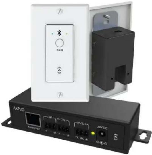
unBT2A
Bluetooth® Audio Wall Plate Receiver for Pro-AV

natural_image
Exterior view of an electronic device with a white panel and black enclosure, showing ports and indicators (no readable text or symbols)User Manual
Date 02/21/20
1675 MacArthur Boulevard · Costa Mesa, CA 92626
Ph: 800/854-4079 or 714/957-7100 · Fax: 714/754-6174
© 2020 QSC, LLC all rights reserved. QSC and the QSC logo are registered trademarks of QSC, LLC in the U.S. Patent and Trademark office and other countries. All other trademarks are the property of their respective owners. Patents may apply or be pending.
www.qsc.com
614-00034
IMPORTANT SAFETY INSTRUCTIONS
The symbols below are internationally accepted symbols that warn of potential hazards with electrical products.

This symbol, wherever it appears, alerts you to the presence of un-insulated dangerous voltage inside the enclosure -- voltage that may be sufficient to constitute a risk of shock.

This symbol, wherever it appears, alerts you to important operating and maintenance instructions in the accompanying literature. Please read the manual.
-
Read these instructions.
-
Keep these instructions.
-
Heed all warnings.
-
Follow all instructions.
-
Do not use this apparatus near water.
-
Clean only with a dry cloth.
-
Do not block any ventilation openings. Install in accordance with the manufacturer's instructions.
-
Do not install near any heat sources such as radiators, heat registers, stoves, or other apparatus (including amplifiers) that produce heat.
-
Do not defeat the safety purpose of the polarized or grounding-type plug. A polarized plug has two blades with one wider than the other. A grounding type plug has two blades and third grounding prong. The wider blade or the third prong is provided for your safety. If the provided plug does not fit into your outlet, consult an electrician for replacement of the obsolete outlet.
-
Protect the power cord from being walked on or pinched particularly at plugs, convenience receptacles, and the point where they exit from the apparatus.
-
Only use attachments/accessories specified by Attero Tech
-
Use only with the cart, stand, tripod, bracket, or table specified by the manufacturer, or sold with the apparatus.
-
When a cart is used, use caution when moving the cart/apparatus combination to avoid injury from tip-over.
-
Unplug this apparatus during lightning storms or when unused for long periods of time.
-
Refer all servicing to qualified service personnel. Servicing is required when the apparatus has been damaged in any way, such as power-supply cord or plug is damaged, liquid has been spilled or objects have fallen into the apparatus, the apparatus has been exposed to rain or moisture, does not operate normally, or has been dropped.
-
This apparatus shall be connected to a mains socket outlet with a protective earthing connection.
-
When permanently connected, on all-pole mains switch with a contact separation of at least 3mm in each pole shall be incorporated in the electrical installation of the building.
-
If rack mounting, provide adequate ventilation. Equipment may be located above or below this apparatus but some equipment (like large power amplifiers) may cause an unacceptable amount of hum of may generate too much heat and degrade the performance of this apparatus,
-
This apparatus may be installed in a industry standard equipment rack. Use screws through all mounting holes to provide the best support.

TO REDUCE THE RISK OF FIRE OR ELECTRIC SHOCK, DO NOT EXPOSE THIS APPARATUS TO RAIN OR MOISTURE.
WARRANTY INFORMATION
For a copy of the QSC Limited Warranty, visit the QSC website at www.qsc.com
Note: This equipment has been tested and found to comply with the limits for a Class A digital device, pursuant to Part 15 of the FCC Rules and EN55022. These limits are designed to provide reasonable protection against harmful interference when the equipment is operated in a commercial environment. This equipment generates, uses and can radiate radio frequency energy and, if not installed and used in accordance with the instruction manual, may cause harmful interference to radio communications. Operation of this equipment in a residential area is likely to cause harmful interference, in which case the user will be required to correct the interference at their own expense.

This symbol means the product must not be discarded as household waste, and should be delivered to an appropriate collection facility for recycling. Proper disposal and recycling helps protect natural resources, human health and the environment. For more information on disposal and recycling of this product, contact your local municipality, disposal service, or the business where you bought this product.
Contents
1 - Overview......4
1.1 - What's in the Box 4
2 - Product Features .... 5
3 - System Connectivity 8
4 - Initial Device Setup 9
4.1 - Factory Reset 9
5 - Mounting and Installation 10
5.1 - Audio Connections.... 11
6 - Bluetooth® Operation 12
7 - 3^rd Party Control....13
7.1 - RS-232 Interface 13
8 - ARCHITECTS & ENGINEERING SPECIFICATION....14
8.1 - Device Specifications.... 1
APPENDIX A – Reference Documents....
- Overview
The unBT2A is single gang Decora style in-wall Bluetooth® audio interface used for adding Bluetooth® audio connectivity to installed audio systems. The unBT2A can be used in any venue where there's a need to stream Bluetooth® audio from a smart phone, laptop, tablet or other Bluetooth® audio equipped smart device to the sound system. The unBT2A features a simple and consistent pairing process to eliminate the frustrating experience users often have with consumer grade Bluetooth® interfaces.
The unBT2A provides cost effective installation and flexibility by utilizing CAT-5 or better, unshielded cabling to transport the analog audio outputs and control to the unBT2A-EXP break out box.
Through the unBT2A EXP expander, the unBT2A outputs balanced mono or stereo analog audio on 3-pin depluggable connectors for easy connection to both professional audio equipment. The unBT2A USB port is used for initial product setup at installation, and the unBT2A EXP has an RS-232 port for 3rd party control in installations featuring an integrated control system.
Features:
- Single gang Decora form factor for easy installation in space constrained applications
Simple pairing one button pairing/connect process for standalone operation with LED indication of connection status
Simple serial control protocol for integration with 3rd party control system via RS-232 (Remote connection management and status monitoring) - Configurable pairing button for flexible integration with and without 3rd party control systems
- Balanced mono/stereo analog outputs for interfacing to both commercial and consumer audio equipment
USB bus-powered connection for simple setup prior to installation and firmware update (Configuration only - audio output not supported when powered via USB)
Customizable advertised friendly name for co-located device applications - Compatible with most smartphones, Apple iPads, and Android tablets and laptop Bluetooth® audio devices
1.1 - What's in the Box
The device comes supplied with the following:
○ (1) unBT2A Wall Plate
(1) unBT2A Expander
- (1) Single gang Decora cover plate cover w/mounting screws
- (1) Mini-USB 3ft cable
(1) 24V AC/DC Power Supply
2 - Product Features
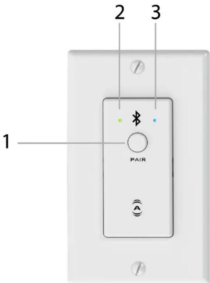
Figure 1 - unBT2A Front Panel Features
| 1 | Bluetooth® pairing/connect button |
| 2 | Bluetooth® status indicator |
| 3 | Power/ID/Error indicator (see note below) |
*Note: The unBT2A is equipped with error reporting features. Upon power up, the power LED will initially light red and then change to green if the device boots successfully. If the LED remains on solid red, this indicates a device failure. If power cycling the unit does not correct this problem, contact Attero Tech technical support.
natural_image
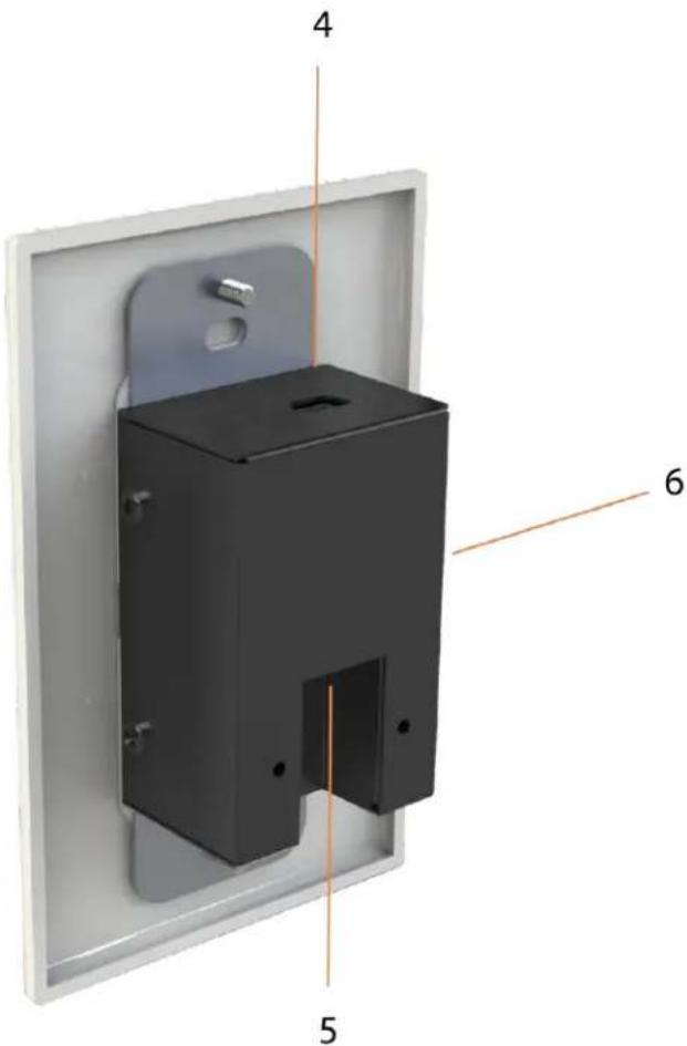
3D diagram of a black rectangular wall-mounted device with labeled components (no text or symbols beyond labels)Figure 2 - unBT2A Rear Panel Features
| 4 | USB Configuration Port |
| 5 | unBT2A-EXP Port ( CAT5/6 connection for Audio, Power, and Control)Note: This is NOT a network port. DO NOT connect to a network switch. |
| 6 | Recessed Factory Reset Switch |
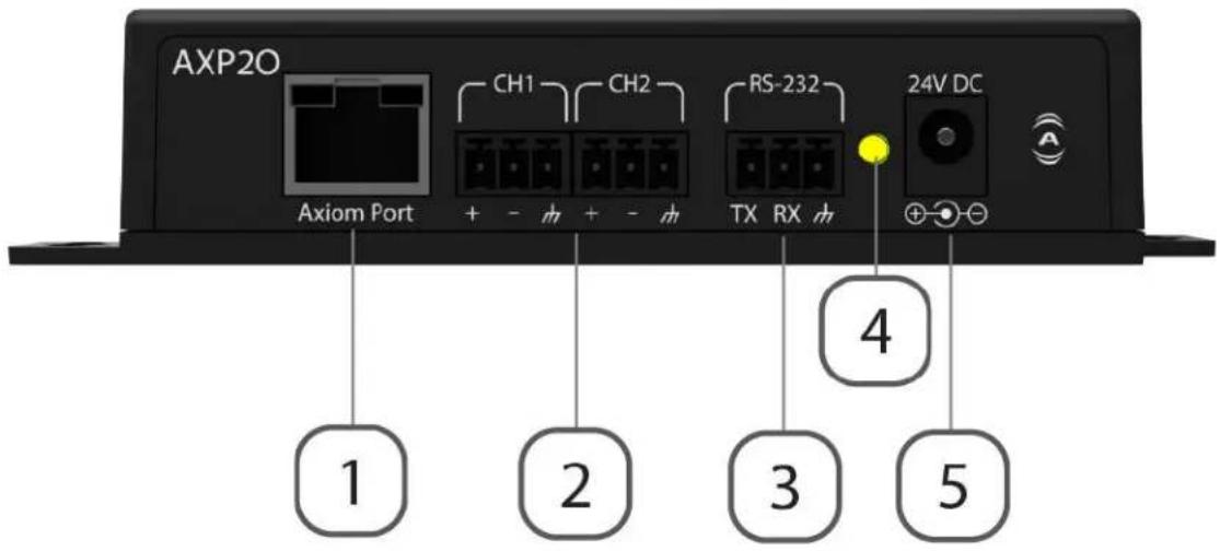
Figure 3 - unBT2A-EXP Features
| 7 | RJ45 – unBT2A Port( CAT5/6 connection for Audio, Power, and Control)Note: This is NOT a network port. DO NOT connect to a network switch. |
| 8 | Balanced Audio Output Terminal Blocks |
| 9 | RS-232 Terminal Block |
| 10 | 24V DC Power Input |
| 11 | Power Status LED |
3 - System Connectivity
The following diagram shows how an unBT2A may be integrated into a typical professional AV installation. In this example, the analog outputs are interfaced to an audio DSP for processing and distribution throughput the venue. The RS-232 is interfaced to a control system to allow extended control over the unBT2A. For a full description of the control API and capabilities, please refer to the unIFY 3 ^rd Party API documentation available at www.atterotech.com.
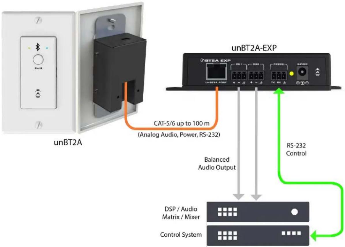
Figure 4 - unBT2A System Integration Diagram
4 - Initial Device Setup
*Note: Once the wall plate is installed in the wall, the USB port used for configuration will not be accessible. It is therefore recommended setup be completed before installing the wall plate into the wall.
The unBT2A features software configuration and status monitoring of the following device parameters using Attero Tech's unIFY Control Panel software (V2.1 or later):
- Bluetooth® friendly name (Default: unBT2A)
○ Mono/Stereo output selection - Analog output sensitivity
○ Pairing button control - unBT2A status
- Remote pairing activation/deactivation
- Clear pairing list
To access these parameters, first install and unIFY Control Panel onto a Windows PC then connect the unBT2A via the mini-USB connection on the unit to allow proper detection. The unIFY Control Panel software comes with the necessary drivers required by the operating system for compatibility with the unBT2A. Once the unIFY Control Panel application is open, select the "unBT2A Configuration" menu item from the "Tools" menu. Then use the drop down to select the COM port the BT2A is using and click the "Connect" button.
*Note: Power supplied via the USB connection is enough to power the unBT2A for initial configuration. While the device will operate normally including allowing pairing, the audio outputs of the unBT2A will not operate while it is powered only via USB. If it is necessary to test the audio output while connected to the USB, connect the unBT2A-EXP and the use the supplied wall wart in order to fully power the device.
For a complete description of the software features, refer to the BT2A section of the unIFY Control Panel user manual.
4.1 - Factory Reset
natural_image
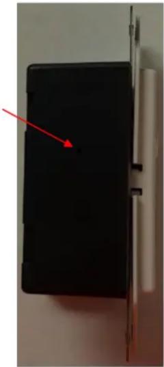
Close-up of a black electronic device with a red arrow pointing to its side panel (no visible text or symbols)The unBT2A has a factory reset option. Using it will reset all the devices parameters back to their factory defaults. The devices IP address mode is also reset back to getting a dynamic IP.
Access to the factory reset button is through a small circular hole on the side of the unit.
To use the factory reset, be sure the unit is powered up and insert a small screwdriver or paperclip into the hole to activate the factory reset switch. There should be a noticeable "click" when it's activated. Hold the switch in for 5 to 10 seconds and release the switch. If the factory reset was successful, the left hand LED will briefly glow red and then change to green. If not, the reset switch was not held in long enough.
4.2 - Firmware Updates
The unBT2A does support field firmware updates. Any new firmware will be made available on the Attero Tech Support Desk web portal. Unlike our other updatable products, the firmware file for a BT2A is provided as a .bin file. This file can then applied by connecting the BT2A to a PC and using the "Update Firmware" feature on the BT2A plug-in within unify Control Panel.
*Note: Only the wall plate contains firmware and it must be connected to a PC via its USB interface to apply any update. This will necessitate removing it from the wall to access it.
5 - Mounting and Installation
A typical installation will involve mounting the wall plate into a pre mounted single-gang or larger wall box, standard drywall bracket or mud ring. Before starting, make sure the wall box where the unBT2A is to be installed is pre-wired with a suitable CAT5e or better cable back to the unBT2A-EXP break out box.
With the unBT2A-EXP powered off, attach the CAT-5e cable from the unBT2A port of the unBT2A-EXP to the RJ45 on the unBT2A. Apply power by plugging in the 24V DC power supply to the DC power input on the unBT2A-EXT. The power LED on the unBT2A-EXT should illuminate green. Additionally, the unBT2A wall plate should also start up and once ready to operate, the front panel power status indicator should also be illuminated green.
*Note: Upon power up, the power LED will initially light red and then change to green if the wall plate boots successfully. If the LED remains on solid red, this indicates a device failure. If power cycling the BT2A does not correct this problem, contact Attero Tech technical support.
With the cable attached, carefully place unBT2A into the wall box taking care to not trap the cabling. Once fully in place, secure it with the screws provided. Once the unit is secured in the wall box, fit the Decora plate over the front of the unit and secure it with the screws provided with it. It is recommended to not over-tighten the screws that attach the included Decora wall plate to prevent cracking it.
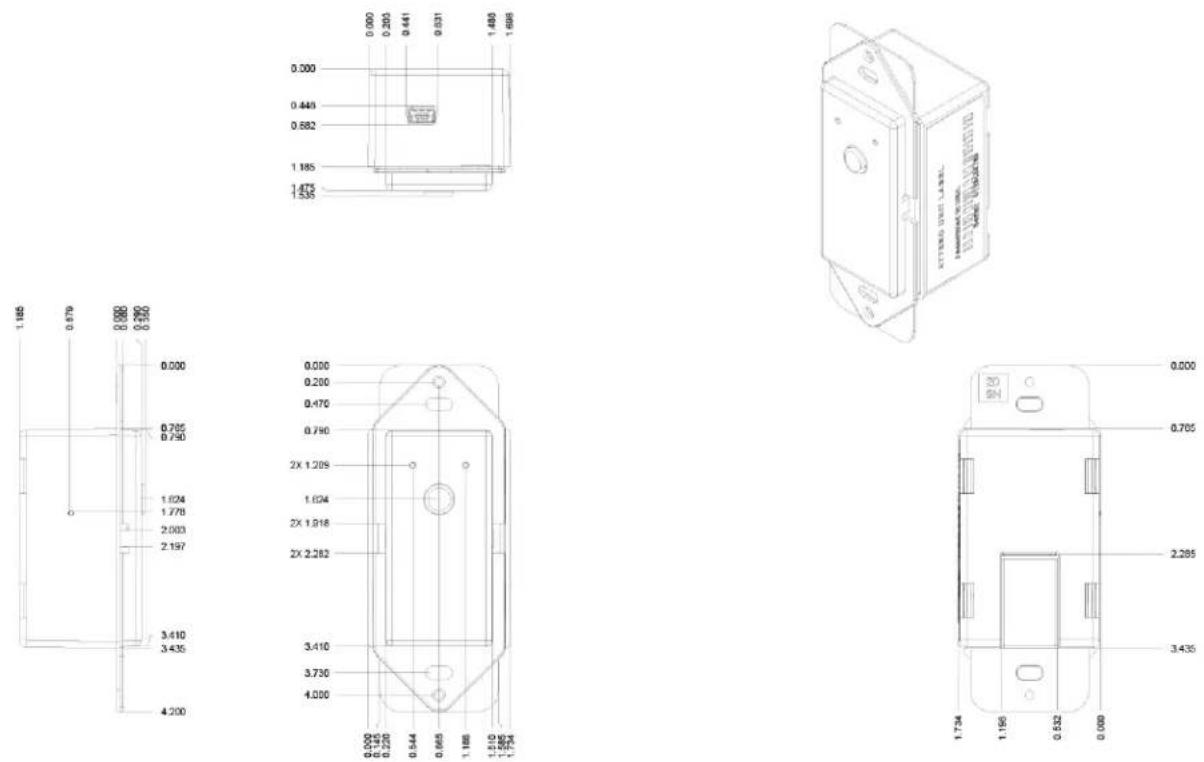
Figure 5 - unBT2A Dimensioned Drawings
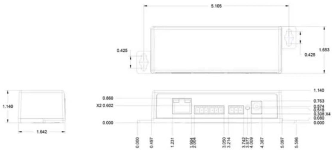
Figure 6 - unBT2A-EXP Dimensioned Drawings
5.1 - Audio Connections
The unBT2A provides balanced audio outputs to external analog audio equipment. Refer to the following diagrams for connecting the outputs of the unBT2A to audio devices.
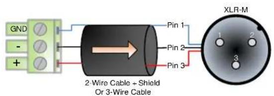
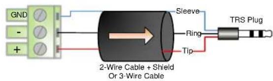
Figure 7 - BT2A to Balanced Input Wiring Guide
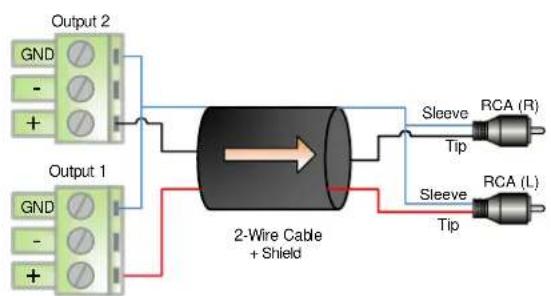
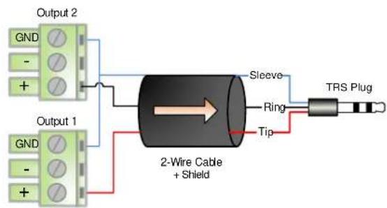
Figure 8 - BT2A to Unbalanced (Stereo) Input Wiring Guide
6 - Bluetooth® Operation
The unBT2Ais designed for two primary usage modes to facilitate a number of professional AV applications.
*Note: Once paired/connected, the Bluetooth® friendly name is visible to other devices. However, while another device may be able to pair and save to its Bluetooth® device list when in this state, breaking the connection of the currently active device will not be possible.
Standalone Operation:
This usage model is intended for applications where casual users of a public venue (sports bar, spa, stadium luxury box, fitness center) have access to connect their devices to the audio system but headaches are minimized by eliminating automatic reconnect and pairing history features.
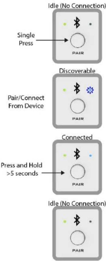
In this mode, users connect their Bluetooth® audio enabled smart device by simply pressing the front panel "PAIR" button. The blue Bluetooth® status LED will begin flashing to indicate that the unBT2A is now visible to other Bluetooth® devices and accepting pairings. This pairing period lasts 60 seconds after which the status LED will stop flashing and turn off and the unBT2A will disable its Bluetooth® interface.
*Note: The default friendly name visible to other devices is "unBT2A". This name can be customized by the installer using the unIFY Control Panel software (v2.1 or greater).
If a successful pairing is made during the pairing period, the status LED will stop flashing and turn constantly on.
To disconnect a device from the unBT2A, press and hold the PAIR button for 5 seconds and then release it. The status LED will turn off, and the connection will be reset. Another device may now be connected by repeating the pairing process.
3rd Party Integration:
In this usage model, the unBT2A is integrated into a large AV system that includes a 3 ^rd party control system. Using the RS-232 control port and the 3 ^rd party programming API, integrators can customize the usage of the unBT2A. The control system the ability to configure the following functions:
Limit errant connections by disabling the front panel control
Implement user privileges by only initiating the pairing/connect process remotely through the control system user interface
Report current unBT2A Bluetooth® interface status to the control system
flowchart
graph TD
    A["Single Press"] --> B["Pair"]
    C["Discoverable"] --> D["Pair"]
    E["Connected"] --> F["PAIR"]
    G["Press and Hold >5 seconds"] --> H["PAIR"]
    I["Idle (No Connection)"] --> J["PAIR"]
Figure 9 - Standalone Operation
7 - 3 ^rd Party Control
The RS-232 port on the unBT2A-EXP break-out box is intended for connectivity to 3^rd party control systems for extended integration of the unBT2A into professional AV applications. All configuration features of the unBT2A available to the installer, except firmware updates, are also supported via the RS-232 interface.
The full command set that the unBT2A supports can be found in the unIFY 3 ^rd party Software API document, available from the registered users section of the Attero Tech website (Go to www.atterotech.com and click on the log-in option).
7.1 - RS-232 Interface
The RS-232 interface operates at 9600 baud (8-N-1 format. The maximum cable length including cabling between the unBT2A-EXP and control device is 100 meters.
8 - ARCHITECTS & ENGINEERING SPECIFICATION
The Bluetooth® interface unit shall provide two analog line level outputs on 3-pin depluggable connectors, software switchable between -10dBV (consumer level) nominal output and +4dBu (professional level) nominal output.
The device shall have soft-ware selection of mono or stereo audio mode. Maximum audio output level shall be +20dBu in the +4dBu mode, and +6dBu in the -10dBVmode.
The device shall have RS-232 real-time control of pairing and other user features over a 3-pin depluggable connector.
The device shall have a USB Mini-B style connector for initial setup.
The device shall be compatible with Attero Tech unIFY software for flexible control and monitoring in system applications. The interface shall be compliant with the RoHS directive. The interface unit shall be compliant with the EMI/EMC requirements for FCC and CE.
The interface shall be the Attero Tech unBT2A.
8.1 - Device Specification
| Audio Inputs | |
| Input Types: | Stereo Bluetooth® v3.0 audio receiver(A2DP Profile only) |
| Range | Approx. 10m (30ft) minimum |
| Audio Outputs | |
| Output Type: | Two balanced line level with automatic muting on loss of A2DP audio streamPhoenix-style 3.81mm de-pluggable terminal blocks |
| Output Sensitivity | +4 dBu / -10dBVSoftware switchable |
| Output Impedance: | 200 Ohms balanced,100 Ohms unbalanced |
| Maximum Output Levels: | +20 dBu (+4dBu Pro Mode)+6dBu a (-10dB - Consumer mode)) |
| Max Cable Length | 100 meters, 24 AWG UTP |
| Audio Output Performance | |
| Dynamic Range: | >87 dB |
| THD+N: | <0.05% @ 1kHz, input signal 3dB below maximum |
| Frequency Response | 20Hz - 20kHz, +1dB /- 3dB |
| RS-232 Port | |
| Baud Rate: | 9600 bps |
| Data Bits | 8 |
| Parity | None |
| Stop Bit | 1 |
| Max Cable Length | 100 meters, 24 AWG UTP |
| Physical Dimensions (unBT2A) | |
| Width | 1.7" |
| Height | 4.2" |
| Depth | 1.2" |
| Weight | 0.2 lbs. |
| Physical Dimensions (unBT2A-EXP) | |
| Width | 5.75" |
| Height | 1.125" |
| Depth | 1.625" |
| Weight | 0.15 lbs. |
| Product Compliance | |
| FCC CFR 47 Parts 15B Class AICES-003CE (EN55022)RoHSREACH | |
| Other | |
| Temperature: | 0 - 40°C |
| Power Consumption | <100mA @ 24V (< 2.4W) |
- unBT2A
- Bluetooth® Audio Wall Plate Receiver for Pro-AV
- User Manual
- IMPORTANT SAFETY INSTRUCTIONS
- WARRANTY INFORMATION
- Contents
- - Overview
- Features:
- - What's in the Box
- - Product Features
- - System Connectivity
- - Initial Device Setup
- - Factory Reset
- - Firmware Updates
- - Mounting and Installation
- - Audio Connections
- - Bluetooth® Operation
- Standalone Operation:
- 3rd Party Integration:
- - 3 rd Party Control
- - RS-232 Interface
- - ARCHITECTS & ENGINEERING SPECIFICATION
- - Device Specification
Brand : QSC
Model : Attero Tech unBT2A
Category : Uncategorized