
DIN-DALI-2 - Joystick Crestron - Free user manual and instructions
Find the device manual for free DIN-DALI-2 Crestron in PDF.


| Product Type | DIN-rail DALI-2 Interface |
| Brand | Crestron |
| Model | DIN-DALI-2 |
| Category | Joystick (Control Interface) |
| Dimensions (H x W x D) | 90 mm x 36 mm x 58 mm (approx.) |
| Weight | 0.2 kg (approx.) |
| Power Supply | Powered via DALI bus (16 V DC typical) |
| Primary Functions | DALI-2 control, monitoring, and integration with Crestron systems |
| Communication Protocol | DALI-2 (IEC 62386) |
| Mounting | DIN rail (EN 60715) |
| Operating Temperature | 0°C to 40°C |
| Storage Temperature | -20°C to 70°C |
| Humidity | 10% to 90% non-condensing |
| Protection Rating | IP20 |
| Compliance | CE, FCC |
| Maintenance | Clean with a soft, dry cloth; do not use liquids |
| Safety | Installation by qualified personnel only |
| Spare Parts | No user-serviceable parts; replace entire unit if faulty |
| General Information | Designed for professional lighting control systems |
Frequently Asked Questions - DIN-DALI-2 Crestron
User questions about DIN-DALI-2 Crestron
0 question about this device. Answer the ones you know or ask your own.
Ask a new question about this device
Download the instructions for your Joystick in PDF format for free! Find your manual DIN-DALI-2 - Crestron and take your electronic device back in hand. On this page are published all the documents necessary for the use of your device. DIN-DALI-2 by Crestron.
USER MANUAL DIN-DALI-2 Crestron
DIN Rail 2 Channel DALI Interface
Programming Guide
Contents
DIN Rail 2 Channel DALI Interface: DIN-DALI-2 1
Introduction ...... 1
Operation of the DIN-DALI-2....2
Power Supplies....2
Communication with Ballasts....2
DALI Wiring Considerations .... 3
Ballast and DIN-DALI-2 Replacement 4
Ballast Replacement....4
DIN-DALI-2 Replacement....6
Advanced DALI Console Commands ....7
Discovering what is on the DALI Loop 7
Viewing the DIN-DALI-2's Stored Memory 8
Addressing Ballasts 11
Constructing DALI Packets....11
Clearing out the DIN-DALI-2 Internal Memory 15
Appendix A: DALI Protocol Summary....16
Appendix B: Ballast Address to Hex Translation....19
Glossary 20
The specific patents that cover Crestron products are listed at patents.crestron.com.
Crestron, the Crestron logo, Cresnet and Crestron Toolbox are either trademarks or registered trademarks of Crestron Electronics, Inc. in the United States and/or other countries. Lutron and EcoSystem are either trademarks or registered trademarks of Lutron Electronics, Inc. in the United States and/or other countries. Other trademarks, registered trademarks and trade names may be used in this document to refer to either the entities claiming the marks and names or their products. Crestron disclaims any proprietary interest in the marks and names of others. Crestron is not responsible for errors in typography or photography.
This document was written by the Technical Publications department at Crestron.
©2013 Crestron Electronics, Inc.
DIN Rail 2 Channel DALI Interface: DIN-DALI-2
Introduction
This guide is intended to help trained Crestron ^® technicians to better troubleshoot and resolve DALI related issues. It offers background information on the operation of the DIN-DALI-2, provides procedures for wiring tests and device replacement, and details the syntax and function of various advanced programming commands. Appendices offer reference materials about DALI protocol.
This guide assumes a general understanding of DALI and familiarity with Crestron Toolbox ^™ software.
Operation of the DIN-DALI-2
The DIN-DALI-2 consists of a DALI power supply, an Ethernet/Cresnet ^® controller, and two independent DALI drivers that are isolated from earth ground and from Ethernet/Cresnet. The following paragraphs provide detailed information on the power supplies, wiring, and ballast communication to assist with troubleshooting the device.
Power Supplies
The DALI loops are not isolated from each other. Loop 1 and Loop 2 share the same common circuit.
The built-in DALI power supply provides 15 V (\~14.8 V) on the DALI lines. Meter measurement shows less since data transmission reduces the average voltage.
The DALI supply uses a current limit set at 250 mA. Drawing more than 250 mA causes the output to collapse. Each loop has its own 250 mA limit. During normal operation, DALI ballasts draw 1 mA each from the loop (2 mA max).
The DALI unit, including DALI bus power supply, can be powered from Cresnet 24 V or from PoE. If both are connected, power is drawn from Cresnet. If both are connected and Cresnet power is removed, the unit resets.
An external slide switch can be used to disable the internal power supply should an external supply be used. This is not recommended and there is no known reason to do this other than for troubleshooting. Sliding the switch to EXT removes power from the loops and causes all ballasts to go to their emergency levels (full).
Communication with Ballasts
In order to communicate, devices short circuit the DALI loop. This causes 250 mA to be drawn from power supply and voltage to collapse. Devices register the voltage on the loop to represent a high or low bit. The DALI specification dictates that a logic low is when the bus voltage is less than 6.5 V while a logic high is greater than 9.5 V. Values in between are not defined. The DIN-DALI-2 uses a threshold of \~7.5 V to determine a low or high state.
Communication between DIN-DALI-2 and ballasts is two-way. Ballasts only talk when queried—when a command is sent to the ballast requesting its level or status.
The DIN-DALI-2 translates the digitals and analogs received from the control system in DALI packets. Since the communication speed on the DALI network is so slow, the DIN-DALI-2 reports a simulated (estimated) position whenever a command is received from the control system. The actual level is requested from the ballasts afterward so an accurate position can be reported to the control system.
The DIN-DALI-2 also polls all ballasts on the loop, regularly requesting their current level and status. The status of the ballast is also queried at a slower pace. This tells the DIN-DALI-2 if a lamp is out or if a ballast has just powered up. It also updates the DIN-DALI-2 internal list of connected ballasts. If a ballast is deemed not connected, it is polled at a much slower rate.
DALI ballasts do not recall their last level on power up. Instead they go to the Power-On Level setting, typically 100%. The DIN-DALI-2 recognizes a ballast has just powered up based on its query status response and sends the correct level to which that ballast should go.
The group information is also updated for any ballasts that power up. This is to accommodate Lutron ^® EcoSystem ^® ballasts that do not store group information in non-volatile memory.
The levels and group information are also sent out whenever the DIN-DALI-2 unit powers up.
The DIN-DALI-2 also stores a complete copy of all information that is stored in the individual ballasts, such as scene levels, groups, addresses, fade time, etc. This is used so that the DIN-DALI-2 can report simulated levels back to the control system without waiting to extract information from each ballast and is also used when replacing a failed ballast (refer to “Ballast Replacement” on page 4 for more information).
DALI Wiring Considerations
The DALI protocol places few restrictions on wiring since data rate is very slow and voltage levels are high.
It is recommended that #18 fire alarm wire with shield be used. This wire size limits the maximum length of a DALI loop. The maximum length of run from the controller to the farthest ballast should not exceed 500 feet (155 meters), but the total wire on the loop can exceed 500 feet (155 meters). For example, it would be acceptable to have ten 100-foot (31-meter) runs to groups of ballasts.
Exceeding the maximum length of a loop affects communication between the ballast and the DIN-DALI-2 controller. Communication is affected in reverse direction (the ballast talking to the DIN-DALI-2) first.
Ballast and DIN-DALI-2 Replacement
The DIN-DALI-2 keeps a record of all ballasts it has commissioned, including all ballast settings such as fade times and groups. If a ballast fails and a replacement is installed, readdressing can take place from the front of the DIN-DALI-2 unit (no laptop necessary).
Ballast Replacement
The following process allows one or more failed DALI ballasts to be replaced with new ballasts. All addressing and programming is transferred to the new ballasts.
The DIN-DALI-2 controls two independent loops of DALI ballasts. Up to 64 ballasts can be connected to each loop. Each ballast must be assigned a unique address (0 - 63). Ballasts typically leave the factory with an “unassigned address” of 255.
The ballasts store information related to addressing, group assignments, presets and fade times programmed during commissioning. When a failed ballast is replaced, all of these parameters must be reprogrammed into the new ballast for it to function correctly.
The DIN-DALI-2 simplifies the replacement process by keeping a copy of all information within its own internal memory. The DIN-DALI-2 identifies that a ballast is missing and discovers a new ballast on the DALI loop. The settings for the missing ballast are transferred to the new ballast.
If there is more than one missing ballast, the installer must select the address to assign to each new ballast. Refer to the following image for button location.
Replacing a Single Ballast
If there is only one ballast to replace, use the following simplified method.
DIN-DALI-2 TEST and ID Up Buttons
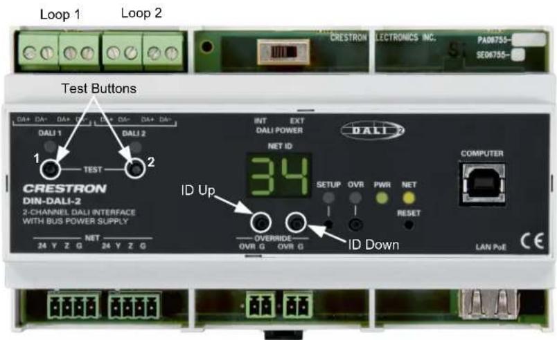
- Te st wiring.
a. Replace the failed ballast.
b. Identify the loop (1 or 2) to which the new ballast is connected.
c. Verify the new ballast can be controlled using the TEST button for the applicable loop. Tapping the TEST button toggles the state of all ballasts connected to that loop.
d. If the ballast does not respond, check the DALI wiring. Wiring must work properly before replacement process continues.
- Initiate device discovery and replacement process.
a. Press and hold the ID Up and ID Down buttons until the display shows br, which takes approximately 5 seconds.
b. Within 10 seconds of entering this mode, tap the TEST button for the loop to which the new ballast is connected. The display blinks br during the device discovery process. This may take a few minutes to complete.
c. When discovery is complete, the display shows the address (in hex) of the missing ballast (00 - 3F) and the new ballast starts flashing.
d. Press and hold the applicable TEST button for 3 seconds to initiate reprogramming of the new ballast.
e. Once the new ballast has been programmed, the DIN-DALI-2 returns to normal operation and displays its Cresnet ID.
Replacing Multiple Ballasts
To replace multiple ballasts, perform the following procedure for each affected loop.
- Test wiring.
a. Replace all failed ballasts.
b. Tap the TEST 1 and TEST 2 buttons to toggle the state of all ballasts connected and verify the new ballasts respond.
c. If a ballast does not respond, check the DALI wiring. Wiring must work properly before replacement process continues.
- Initiate device discovery and replacement process.
a. Press and hold the ID Up and ID Down buttons until the display shows br, which takes approximately 5 seconds.
b. Within 10 seconds of entering this mode, tap the TEST 1 button (for loop 1) or the TEST 2 button (for loop 2). The display blinks br during the device discovery process This may take a few minutes to complete.
c. When discovery is complete, the first new ballast found on the loop flashes to indicate that it has been selected for addressing.
d. The display shows the address (in hex) of the first missing ballast (00 - 3F).
a. Use the ID Up and ID Down buttons to select the address to assign to the flashing ballast. Refer to floor maps created during initial commissioning to determine correct address.
e. Press and hold the TEST 1 button (for loop 1) or TEST 2 button (for loop 2) button for 3 seconds to initiate reprogramming of the selected ballast. The display switches to show the address (in hex) of the next missing ballast and the next new ballast begins flashing.
f. Use the ID Up and ID Down buttons to assign an address to the flashing ballast.
g. Press and hold the TEST 1 button (for loop 1) or TEST 2 button (for loop 2) button for 3 seconds to initiate reprogramming of the selected ballast.
h. Repeat this process for each new ballast on the loop. After the final new ballast has been reprogrammed, the DIN-DALI-2 returns to normal operation and displays the Cresnet ID.
DIN-DALI-2 Replacement
The following process allows a failed DIN-DALI-2 controller to be replaced with a new unit. The ballast addresses and settings are extracted from the network and stored in the new DIN-DALI-2 controller.
The DIN-DALI-2 controls two independent loops of DALI ballasts. Up to 64 ballasts can be connected to each loop. Each ballast must be assigned a unique address (0 – 63). Ballasts typically leave the factory with an “unassigned address” of 255. The ballasts also store information related to group assignments, presets and fade times programmed during commissioning.
The DIN-DALI-2 requires a copy of all information within its own internal memory. The following procedure causes the DIN-DALI-2 to query the network and extract all information from the existing ballasts. Information is stored within the DIN-DALI-2 permanent memory for future use.
DIN-DALI-2 TEST and ID Up Buttons
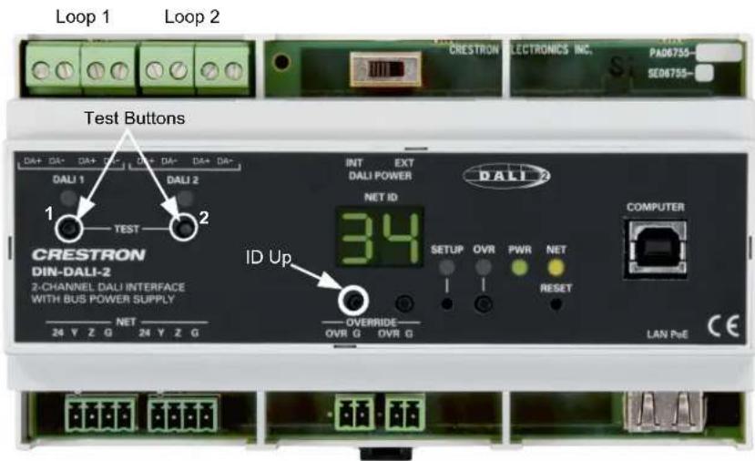
To initiate read back on each loop:
-
Press and hold the ID Up button until the display reads rc, which takes approximately 5 seconds.
-
Within 10 seconds of entering this mode, tap the TEST 1 button (for loop 1) or the TEST 2 button (for loop 2). The display blinks rc while the device discovery process is running. This may take a few minutes to complete.
Once the data extraction has completed, the DIN-DALI-2 returns to normal operation and displays its Cresnet ID.
Advanced DALI Console Commands
DALI console commands are available for almost all functions that can be executed from the DALI configuration tool. In most cases it is much simpler to use the software tool, but console commands are sometimes the only way to accomplish lower level debugging.
Console commands can be viewed using Help debug.
The syntax of the command generally follows:
[Command] [LOOP] [ADDRESS] [additional data]
- LOOP is 1 or 2.
- ADDRESS is a value between 0 and 63 or ALL if the command should go out as a broadcast to everyone. The address UNDEFINED may also be used for ballasts that have not been addressed.
The following sections discuss several helpful commands in detail.
Discovering what is on the DALI Loop
The software tool does not always show the true state of what is on the loop. It may not show all devices or it may still show devices no longer present. The discovery process can be run using the DALIDISCOVER command.
Recommended syntax: DALIDISCOVER [LOOP]
This command triggers a search for ballasts by short address and then by random addresses on the loop specified. The short address search simply involves querying every short address 0–63 for the ballast's long (or random) address. The random address search is a binary search that queries ballasts based on the long address for its short address. The binary search finds any ballasts on the link as long as they have unique long addresses. Ballasts may only have duplicate long addresses if they are in their factory default state and no addressing has been performed (long address = 0xFFFFFFF). The probability of duplicate long address by random chance is essentially 0%.
QUICK can be included in the command to search only based on short address. This is not recommended as ballasts that have duplicate short addresses or no address assigned do not show up.
Alternative syntax: DALIDISCOVER [LOOP] [QUICK]
The discover process takes a few minutes. At the end it displays a list of short address and long addresses. The following are some of the possible results:
- Duplicate short addresses: Address conflicts exist and should be resolved using the software tool or using the DALISETADDRBYRND command.
- Invalid short addresses of 255: A ballast has not been addressed.
- Invalid/duplicate long addresses of 0xFFFF: One or more ballasts are in the factory default state and have not been addressed.
- Total number of entries does not match the number of ballasts on the loop: Multiple ballasts have not been addressed. They all have short addresses of 255 and long addresses of 0xFFFF and so only show up as one entry.
Resolve this by running Setup—Addressing (of unassigned ballasts) in software tool or by using the DALITEACHBYRND command.
Viewing the DIN-DALI-2's Stored Memory
The DIN-DALI-2 unit stores a copy of the information that is stored in the ballast. It also stores records related to whether a ballast is connecting and reporting on the network and whether a ballast was ever commissioned. This data is used to populate the status table in the software tool assigning ballasts as new or missing.
The data can be viewed using the LISTBALCFG command. Note that this only displays the data stored in the DIN-DALI-2 and not necessarily the actual data in the ballasts. Under normal operation they should match.
Syntax: LISTBALCFG [LOOP] [Address] [Parameter]
Possible Values for [Parameter]
| VALUE DATA DISPLAYED | |
| POWERON | Level to which that ballast powers on |
| SYSFAIL | Level ballast goes to when DALI loop voltage disappears |
| MIN Ballast minimum level | |
| MAX | Ballast maximum level |
| PHYMIN Ballast physical minimum level | |
| FADETIME Fade time (refer to DALI Fadetime lookup table) | |
| FADERATE Fade rate (refer to DALI Faderate lookup table) | |
| SCENE0 – SCENE15 Scene levels | |
| GROUP* | The groups of which that ballast is a part |
| STATUS* | STATUS byte—contains info about lamp failure |
| LEVEL | Current level |
| CONNECTED* | Displays whether ballast is showing up on Network during normal polling |
| TARGET | Level to which ballast is ramping |
| TYPE | Ballast type – no relevance |
| VERSION | Version – no relevance |
| COMMISSIONED* | Displays whether ballast was commissioned from this unit to determine whether the data possessed is correct |
| RANDOM | The long address or random address of ballast (24 bits) |
| NAME | The name of the ballast if programmed by tool |
* Command is useful for debugging.
Refer to the following paragraphs for details on several useful commands and their proper syntax.
• LISTBALCFG [LOOP] ALL CONNECTED
The CONNECTED flag is a number from 0–5 that represents the number of consecutive polls to which the ballast has responded.
5: Ballast has responded successfully to the last five poll requests and is communicating well.
0: Ballast has not responded to any of the last five poll requests and is likely not connected.
1-4: Intermediate values indicate some form of problem.
NOTE: The values should not be read immediately after powering up the system as ballasts may not have been polled five times yet.
• LISTBALCFG [LOOP] ALL COMMISSIONED
The COMMISSIONED flag is 0 or 1.
1: The ballast was commissioned and the DIN-DALI-2 expects to see it on the loop. If the ballast is not physically present, the DIN-DALI-2 reports it as missing and tries to replace the address during the ballast replacement process.
0: The ballast was not commissioned as is not expected to be on the loop. If there is a ballast found at that address, the DIN-DALI-2 reports it as new and tries to assign it an address for a missing ballast if one exists.
- LISTBALCFG [LOOP] ALL FADETIME
ALL FADETIME displays the fade time used when scenes are recalled or intensity commands (analogs) are sent. The fade time is mapped into real time as shown in the following table.
Ballast Settings and Fade Times
| BALLAST SETTING | FADE TIME |
| 0 <0.7 s | |
| 1 0.7 s | |
| 2 1 s | |
| 3 1.4 s | |
| 4 2 s | |
| 5 2.8 s (Default) | |
| 6 4 s | |
| 7 5.6 s | |
| 8 8 s | |
| 9 11.3 s | |
| 10 16 s | |
| 11 22.6 s | |
| 12 32 s | |
| 13 45.2 s | |
| 14 64 s | |
| 15 90.5 s |
- LISTBALCFG [LOOP] ALL FADERATE
ALL FADERATE displays the fade rate used when raise/lower commands (digitals) are sent. The fade rate is mapped into steps/second as shown in the table on the following page.
Ballast Settings and Fade Rates
| BALLAST SETTING | FADE RATE |
| 0 N/A | |
| 1 357 steps/s | |
| 2 253 steps/s | |
| 3 178 steps/s | |
| 4 126 steps/s | |
| 5 89 steps/s | |
| 6 63 steps/s | |
| 7 45 steps/s (Default) | |
| 8 32 steps/s | |
| 9 22 steps/s | |
| 10 16 steps/s | |
| 11 11 steps/s | |
| 12 8 steps/s | |
| 13 6 steps/s | |
| 14 4 steps/s | |
| 15 3 steps/s | |
The effective dimming range is on 128 steps so the time required to raise/lower from min to max is approximately 128/fade rate.
The default setting of 7 (45 steps/s) provides a fade rate of 2.8 s.
• LISTBALCFG [LOOP] ALL GROUP
This displays the groups to which each ballast is assigned.
• LISTBALCFG [LOOP] ALL MIN
This displays the minimum dim level that the ballasts can dim to. Note that the DIN-DALI-2 does not allow min to be set to a value less than 128. Even though this is half the useable dimming range it corresponds to a light level of 3% based on logarithmic curve specified by DALI standards.
- READBALCFG [LOOP] ALL
(Read Ballast Configuration data from the ballast)
This retrieves all ballast information and overwrites internal memory. Note that this does not clear the COMMISSIONED flag. It simply reads all group levels, scene levels, fade time, and so on.
The LISTBALCFG command must be used to view the data once it has been read.
- SETBALCFG [LOOP] ALL
(Set Ballast Configuration data within the ballast)
This sets parameters within the ballast. It should be performed through the software tool, not over the console.
Addressing Ballasts
The addressing process can be triggered from the console using the DALITEACHBYRND command.
Syntax: DALITEACHBYRND [LOOP] [ALL or UNASSIGNED]
The command can be executed to address all ballasts on the loop or just those that do not have an address assigned yet. If all ballasts are not showing up during device discovery but are responding to broadcast commands then there are likely ballasts that have not been assigned an address. Running the command should expose these. Readdressing everything is often the best solution as duplicate addresses may cause problems that are difficult to discover.
NOTE: Readdressing ballasts does not wipe out any grouping or scene information that may be stored in the ballasts.
Constructing DALI Packets
For lower level troubleshooting, the DIN-DALI-2 console allows raw DALI packets to be constructed and the responses displayed.
If the response from the ballast must be displayed on the console, the debug console must first be enabled and standard polling of ballasts must be disabled. Without polling disabled the console window fills with messages, making it difficult to see specific ballast responses.
Enter the following commands to disable polling on both loops:
- DALIPOLL 1 STOP
- DALIPOLL 2 STOP
Enter the following commands to enable receive and transmit debug traces.
- DEBUGDALI RX ON
- DEBUGDALI TX ON
Once the console has been enabled any traffic on the DALI outputs is reported. Pressing the DALI TEST buttons shows commands broadcasted to the ballasts.
The SENDDALIPKT command can now be used to communicate directly with a specific ballast or group of ballasts. The paragraphs beginning on the following page illustrate different ways to use the command.
NOTE: When work is complete, the console must be disabled and polling must be re-enabled. Without polling enabled, the DIN-DALI-2 does not report levels and Ballast replacement is not possible.
To disable receive and transmit debug traces, use the commands DEBUGDALI RX OFF and DEBUGDALI TX OFF. To enable polling on both loops, use the commands DALIPOLL 1 START and DALIPOLL 2 START.
- Syntax: SENDDALIPKT [LOOP] [ADDR+DATA]
The ADDR+DATA is the raw DALI packet. For more general information on DALI protocol, refer to the DALI protocol summary in Appendix A, which begins on page 16.
The ADDR portion determines whether the command is a broadcast to a group or to a single short address. It also determines whether the DATA byte is an intensity or a Special Command. Note that both ADDR and DATA are in hex. Refer to Appendix B on page 19 for ballast address to hex address translation.
Command Types and Equivalent Addresses
| COMMAND TYPE | ADDRESS* |
| Broadcast 1111111S | |
| Group 100AAAAS | |
| Single 0AAAAAAS |
* AAAA = 0 to F (Group Address 0-15); AAAAAAA = 0 to 3F (Short Address 0-63); S determines whether DATA byte is an intensity (S=0) or a Special Command (S=1)
- Syntax:
SENDDALIPKT 1 [Short address * 2 + 1] [COMMAND]
SENDDALIPKT 1 [Group address * 2 + 129] [COMMAND]
The following tables provide examples of the completed syntax for each command used with various addresses.
Typical commands to use are:
Go to Max (05)
Go to Min (06)
Go Off (00)
⇒ Query Status (90)
Examples for Sending Ballast to Max Level
| ADDRESS COMMAND | |
| Short address 00 | SENDDALIPKT 1 0105 |
| Short address 06 | SENDDALIPKT 1 0D05 |
| Short address 63 | SENDDALIPKT 1 7F05 |
| Group address 00 | SENDDALIPKT 1 8105 |
Examples for Sending Ballast to Min Level
| ADDRESS COMMAND | |
| Short address 00 | SENDDALIPKT 1 0106 |
| Short address 06 | SENDDALIPKT 1 0D06 |
| Short address 63 | SENDDALIPKT 1 7F06 |
| Group address 01 | SENDDALIPKT 1 8306 |
Examples for Sending Ballast to Off
| ADDRESS COMMAND | |
| Short address 00 | SENDDALIPKT 1 0100 |
| Short address 06 | SENDDALIPKT 1 0D00 |
| Short address 63 | SENDDALIPKT 1 7F00 |
| Group address 15 | SENDDALIPKT 1 9F00 |
Examples for Querying Status
| ADDRESS COMMAND | |
| Short address 00 | SENDDALIPKT 1 0190 |
| Short address 06 | SENDDALIPKT 1 0D90 |
| Short address 63 | SENDDALIPKT 1 7F90 |
- Syntax: SENDDALIPKT [LOOP] [ADDR] [DATA]
NOTE: There is no space between the ADDR and DATA bytes.
Refer to the following tables when generating raw DALI packets.
Byte Equivalents for Short and Group Addresses
| SHORT ADDRESS | ADDR BYTE | SHORT ADDRESS | ADDR BYTE | SHORT ADDRESS | ADDR BYTE | SHORT ADDRESS | ADDR BYTE | GROUP ADDRESS | ADDR BYTE |
| 0 | 01 | 16 | 21 | 32 | 41 | 48 | 61 | 0 | 81 |
| 1 | 03 | 17 | 23 | 33 | 43 | 49 | 63 | 1 | 83 |
| 2 | 05 | 18 | 25 | 34 | 45 | 50 | 65 | 2 | 85 |
| 3 | 07 | 19 | 27 | 35 | 47 | 51 | 67 | 3 | 87 |
| 4 | 09 | 20 | 29 | 36 | 49 | 52 | 69 | 4 | 89 |
| 5 | 0B | 21 | 2B | 37 | 4B | 53 | 6B | 5 | 8B |
| 6 | 0D | 22 | 2D | 38 | 4D | 54 | 6D | 6 | 8D |
| 7 | 0F | 23 | 2F | 39 | 4F | 55 | 6F | 7 | 8F |
| 8 | 11 | 24 | 31 | 40 | 51 | 56 | 71 | 8 | 91 |
| 9 | 13 | 25 | 33 | 41 | 53 | 57 | 73 | 9 | 93 |
| 10 | 15 | 26 | 35 | 42 | 55 | 58 | 75 | 10 | 95 |
| 11 | 17 | 27 | 37 | 43 | 57 | 59 | 77 | 11 | 97 |
| 12 | 19 | 28 | 39 | 44 | 59 | 60 | 79 | 12 | 99 |
| 13 | 1B | 29 | 3B | 45 | 5B | 61 | 7B | 13 | 9B |
| 14 | 1D | 30 | 3D | 46 | 5D | 62 | 7D | 14 | 9D |
| 15 | 1F | 31 | 3F | 47 | 5F | 63 | 7F | 15 | 9F |
Commands and Equivalent DATA Bytes
| Command DATA Byte | |
| OFF 00 | |
| MAX 05 | |
| MIN 06 | |
| RESET 20 | |
| QUERY STATUS 90 | |
| QUERY LEVEL A0 | |
| QUERY GROUPS 0-7 C0 | |
| QUERY GROUPS 8-15 | C1 |
The query command results in a response from the ballast if it is present. Typically this is all that is needed to prove reliable communication back from the ballast. The byte received can also provide further information.
- Bit 0: Value of 0 means ballast is okay. Value should always be 0.
- Bit 1: Value of 0 means lamp is okay. Value of 1 means lamp is burned out. Use this to verify burned out lamps.
• Bit 2: Value of 0 means ballast is off. - Bit 3 - 6: Ignore
- Bit 7: Value of 0 means power is okay. Value of 1 means power cycled since last intensity command.
Clearing out the DIN-DALI-2 Internal Memory
If addresses of ballasts are changed via console commands or if ballasts are removed or replaced during the commissioning phase, the internal copy of ballast settings may not match what is installed. Typically the internal memory retains the previous settings for a ballast and then shows the new settings as a new ballast. The status list shows a ballast with the previous address as missing and a ballast with the new settings as new.
If this occurs, the internal memory in the DIN-DALI-2 should be cleared and the latest settings read back in from the ballasts. Both can be achieved using the software tool.
To clear internal memory, go to the DALI Commissioning Tool in Crestron Toolbox, click Setup, and select Clear Commission Settings.
To read back ballast info (what ballasts are on the network and all their parameters), go to the DALI Commissioning Tool in Crestron Toolbox, click Setup and select Replace DIN-DALI-2 settings with ballast settings.
The DIN-DALI-2 should now show only the ballasts that are physically present.
It is important that internal memory matches what is stored in the ballasts so that future ballast replacement can take place without recommissioning the system.
Appendix A: DALI Protocol Summary
DALI uses a Manchester encoded unidirectional serial protocol with a transmission rate of 1.2 kHz. The bit time is 833 μs ±10%.
The frame of the main unit consists of 19 bits (15.9 ms):
• 1 start-bit (logical 1)
- 8 address bits
- 8 data bits
- 3top bits (physical high level)
The answer frame of the sub unit consists of 11 bits (9.2 ms):
- start-bit (logical 1)
- data bits
- Stop bits (physical high level)
DALI Protocol Configuration
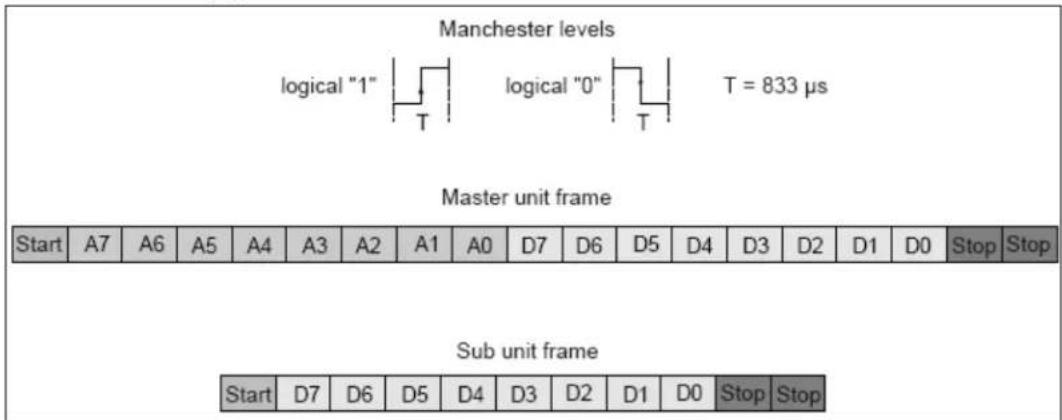
To select the devices by the different addressing modes (broadcast, group, single), use the address types shown in the following table.
Addresses Used for Different Command Types
| COMMAND TYPE | ADDRESS* | NOTES |
| Broadcast 1111111S | ||
| Group | 100AAAAS | AAAA = 0 to F (Group Address 0-15) |
| Single | 0AAAAAAS | AAAAAA = 0 to 3F (Short Address 0-63) |
| Special command: 10 | 1CCCC1;110CCCC1 | CCCC = special command number |
* The S distinguishes between a direct arc power command and a DALI command. If S = 0 the following data is interpreted as a power level with a value between 0x00 (off) and 0xFE (maximum power level).
Standard commands are listed in the table beginning on the following page.
Standard Commands
| COMMAND NUMBER | ADDRESS | COMMAND/DATA | COMMAND NAME |
| - | YAAAAAA0 | XXXX XXXX | DIRECT ARC POWER CONTROL |
| 0 YAAAAAA1 | 00000000 OFF | ||
| 1 YAAAAAA1 | 00000001 UP | ||
| 2 YAAAAAA1 00000010 DOWN | |||
| 3 YAAAAAA1 | 00000011 STEP UP | ||
| 4 YAAAAAA1 | 00000100 | STEP DOWN | |
| 5 | YAAAAAA1 | 00000101 | RECALL MAX LEVEL |
| 6 YAAAAAA1 | 00000110 | RECALL MIN LEVEL | |
| 7 YAAAAAA1 | 00000111 | STEP DOWN AND OFF | |
| 8 | YAAAAAA1 | 00001000 | ON AND STEP UP |
| 9–15 | YAAAAAA1 | 00001XXX | RESERVED |
| 16–31 | YAAAAAA1 | 0001XXXX | GO TO SCENE |
| 32 | YAAAAAA1 | 00100000 | RESET |
| 33 | YAAAAAA1 | 00100001 | STORE ACTUAL LEVEL IN THE DTR |
| 34–41 | YAAAAAA1 | 0010XXXX | RESERVED |
| 42 | YAAAAAA1 | 00101010 | STORE THE DTR AS MAX LEVEL |
| 43 | YAAAAAA1 | 00101011 | STORE THE DTR AS MIN LEVEL |
| 44 | YAAAAAA1 | 00101100 | STORE THE DTR AS SYSTEM FAILURE LEVEL |
| 45 | YAAAAAA1 | 00101101 | STORE THE DTR AS POWER ON LEVEL |
| 46 | YAAAAAA1 | 00101110 | STORE THE DTR AS FADE TIME |
| 47 | YAAAAAA1 | 00101111 | STORE THE DTR AS FADE RATE |
| 48–63 | YAAAAAA1 | 0011XXXX | RESERVED |
| 64–79 | YAAAAAA1 | 0100XXXX | STORE THE STR AS SCENE |
| 80–95 | YAAAAAA1 | 0101XXXX | REMOVE FROM SCENE |
| 96–111 | YAAAAAA1 | 0110XXXX | ADD TO GROUP |
| 112–127 | YAAAAAA1 | 0111XXXX | REMOVE FROM GROUP |
| 128 | YAAAAAA1 | 10000000 | STORE DTR AS SHORT ADDRESS |
| 129–143 | YAAAAAA1 | 1000XXXX | RESERVED |
| 144 | YAAAAAA1 | 10010000 | QUERY STATUS |
| 145 | YAAAAAA1 | 10010001 | QUERTY BALLAST |
| 146 | YAAAAAA1 | 10010010 | QUERY LAMP FAILURE |
| 147 | YAAAAAA1 | 10010011 | QUERY LAMP POWER ON |
| 148 | YAAAAAA1 | 10010100 | QUERY LIMIT ERROR |
| 149 | YAAAAAA1 | 10010101 | QUERY RESET STATE |
| 150 | YAAAAAA1 | 10010110 | QUERY MISSING SHORT ADDRESS |
| 151 | YAAAAAA1 | 10010111 | QUERY VERSION NUMBER |
| 152 | YAAAAAA1 | 10011000 | QUERY CONTENT DTR |
| 153 | YAAAAAA1 | 10011001 | QUERY DEVICE TYPE |
| 154 | YAAAAAA1 | 10011010 | QUERY PHYSICAL MINIMUM LEVEL |
| 155 YAAAAAA1 | 10011011 | QUERY POWER FAILURE | |
| 156–159 | YAAAAAA1 | 100111XX | RESERVED |
| 160 | YAAAAAA1 | 10100000 | QUERY ACTUAL LEVEL |
| 161 | YAAAAAA1 | 10100001 | QUERY MAX LEVEL |
| 162 | YAAAAAA1 | 10100010 | QUERY MIN LEVEL |
| 163 | YAAAAAA1 | 10100011 | QUERY POWER ON LEVEL |
| 164 | YAAAAAA1 | 10100100 | QUERY SYSTEM FAILURE LEVEL |
| 165 | YAAAAAA1 | 10100101 | QUERY FADE TIME / FADE RATE |
| 166–175 | YAAAAAA1 | 1010XXXX | RESERVED |
| 176–191 | YAAAAAA1 | 1011XXXX | QUERY SCENE LEVEL (SCENES 0–15) |
| 192 | YAAAAAA1 | 11000000 | QUERY GROUPS 0–7 |
| 193 | YAAAAAA1 | 11000001 | QUERY GROUPS 8–15 |
| 194 | YAAAAAA1 | 11000010 | QUERY RANDOM ADDRESS (H) |
| 195 | YAAAAAA1 | 11000011 | QUERY RANDOM ADDRESS (M) |
| 196 | YAAAAAA1 | 11001100 | QUERY RANDOM ADDRESS (L) |
| 197–223 | YAAAAAA1 | 10XXXXX | RESERVED |
Appendix B: Ballast Address to Hex Translation
Refer to the following table when translating ballast address to hex addresses.
Hex and Ballast Address Conversion Table
| BALLAST ADDRESS | HEX ADDRESS | BALLAST ADDRESS | HEX ADDRESS | BALLAST ADDRESS | HEX ADDRESS | BALLAST ADDRESS | HEX ADDRESS |
| 0 | 00 | 16 | 10 | 32 | 20 | 48 | 30 |
| 1 | 01 | 17 | 11 | 33 | 21 | 49 | 31 |
| 2 | 02 | 18 | 12 | 34 | 22 | 50 | 32 |
| 3 | 03 | 19 | 13 | 35 | 23 | 51 | 33 |
| 4 | 04 | 20 | 14 | 36 | 24 | 52 | 34 |
| 5 | 05 | 21 | 15 | 37 | 25 | 53 | 35 |
| 6 | 06 | 22 | 16 | 38 | 26 | 54 | 36 |
| 7 | 07 | 23 | 17 | 39 | 27 | 55 | 37 |
| 8 | 08 | 24 | 18 | 40 | 28 | 56 | 38 |
| 9 | 09 | 25 | 19 | 41 | 29 | 57 | 39 |
| 10 | 0A | 26 | 1A | 42 | 2A | 58 | 3A |
| 11 | 0B | 27 | 1B | 43 | 2B | 59 | 3B |
| 12 | 0C | 28 | 1C | 44 | 2C | 60 | 3C |
| 13 | 0D | 29 | 1D | 45 | 2D | 61 | 3D |
| 14 | 0E | 30 | 1E | 46 | 2E | 62 | 3E |
| 15 | 0F | 31 | 1F | 47 | 2F | 63 | 3F |
Glossary
Binary Search
This is the method by which ballasts are found using the long address. Since the long address is 24 bits, it would take too long to query every address. Instead a binary search queries any ballasts below an address. All ballast with an address less than the value specified responds. The DIN-DALI-2 hears the response and repeats the process with a lower value (half the original). If the DIN-DALI-2 does not hear a response then it retries with a higher value (in between the last two values). This process repeats until a single ballast is found—that is, when a response is heard after querying long address 0xLLLLLL but not after querying 0xLLLLLL-1. The ballast with long address 0xLLLLLL is then assigned the next available short address and is instructed to not respond to any further binary search queries. The process starts again until another ballast is found and addressed. The process repeats until no further ballasts can be found.
Long Address (also known as Random Address)
This is a 24-bit random number generated during the addressing phase that allows commands to be sent to ballasts that do not have short addresses. The value of 0xFFFFF is reserved for unassigned ballasts. A ballast typically leaves the factory with a long address of 0xFFFFF.
Short Address
This is the address used under normal operation. It is a value between 0-63. A value of 255 (0xFF) is reserved for unassigned ballasts. A ballast typically leaves the factory with a short address of 255.
This page is intentionally left blank.
- DIN Rail 2 Channel DALI Interface
- Programming Guide
- Contents
- DIN Rail 2 Channel DALI Interface: DIN-DALI-2 1
- DIN Rail 2 Channel DALI Interface: DIN-DALI-2
- Introduction
- Operation of the DIN-DALI-2
- Power Supplies
- Communication with Ballasts
- DALI Wiring Considerations
- Ballast and DIN-DALI-2 Replacement
- Ballast Replacement
- Replacing a Single Ballast
- Replacing Multiple Ballasts
- DIN-DALI-2 Replacement
- Advanced DALI Console Commands
- Discovering what is on the DALI Loop
- Recommended syntax: DALIDISCOVER [LOOP]
- Alternative syntax: DALIDISCOVER [LOOP] [QUICK]
- Viewing the DIN-DALI-2's Stored Memory
- Addressing Ballasts
- Constructing DALI Packets
- Clearing out the DIN-DALI-2 Internal Memory
- Appendix A: DALI Protocol Summary
- Appendix B: Ballast Address to Hex Translation
- Glossary
- Binary Search
- Long Address (also known as Random Address)
- Short Address
Brand : Crestron
Model : DIN-DALI-2
Category : Joystick