
GT20-TM - Sonar GARMIN - Free user manual and instructions
Find the device manual for free GT20-TM GARMIN in PDF.


| Product Type | Fishfinder Transducer |
| Brand | Garmin |
| Model | GT20-TM |
| Sonar Technology | ClearVü and Traditional CHIRP |
| Mounting Options | Transom Mount or Trolling Motor Mount |
| Cable Length | 6 m (20 ft) |
| Frequency | 455/800 kHz (ClearVü), 200/77 kHz (Traditional) |
| Power Input | Passive (connects to chartplotter) |
| Transducer Type | Dual beam |
| Housing Material | Plastic |
| Bracket Material | Stainless steel |
| Waterproof Rating | IPX7 (estimated) |
| Anti-fouling | Compatible with water-based anti-fouling paint |
| Installation Tools Required | Number 2 Phillips screwdriver, drill, drill bits, marine sealant, waterproof tape (for trolling motor) |
| Warranty | 1 year (standard Garmin warranty) |
| Weight | Approx. 0.5 kg |
| Dimensions (approx.) | 150 x 50 x 30 mm |
| Includes | Transducer, transom mount bracket, trolling motor mount, hardware, template, cable clamps, cable-entry cover |
Frequently Asked Questions - GT20-TM GARMIN
User questions about GT20-TM GARMIN
0 question about this device. Answer the ones you know or ask your own.
Ask a new question about this device
Download the instructions for your Sonar in PDF format for free! Find your manual GT20-TM - GARMIN and take your electronic device back in hand. On this page are published all the documents necessary for the use of your device. GT20-TM by GARMIN.
USER MANUAL GT20-TM GARMIN
Garmin ClearVü™ Transducer Transom/Trolling Motor Mount

natural_image
Black mechanical device with attached lever on water surface, no visible text or symbolsInstallation Instructions
Important Safety Information
WARNING
See the Important Safety and Product Information guide in the chartplotter or fishfinder product box for product warnings and other important information.
You are responsible for the safe and prudent operation of your vessel. Sonar is a tool that enhances your awareness of the water beneath your boat. It does not relieve you of the responsibility of observing the water around your boat as you navigate.
CAUTION
Failure to install and maintain this equipment in accordance with these instructions could result in damage or injury.
NOTICE
This equipment should be installed by a qualified marine installer.
To obtain the best performance and to avoid damage to your boat, you must install the Garmin ® device according to these instructions.
Read all installation instructions before proceeding with the installation. If you experience difficulty during the installation, go to support.garmin.com for more information.
Tools Needed
• Number 2 Phillips screwdriver
Transom mount
- Drill
- Drill bits: 4 mm ( 5/32 in.), 3.2 mm ( 1/8 in.), 25 mm (1 in.)
- Masking tape
- Marine sealant
Trolling motor mount
- Waterproof tape
Preparing the Transducer for Long-Term Exposure to Water
NOTICE
Do not use acetone or acetone-based products on the transducer. Acetone damages the plastic transducer housing.
When you install a transducer on a boat that spends a significant amount of time in the water, you should coat the transducer and mounting hardware with a water-based anti-fouling paint to prevent marine growth.
1 Lightly sand the transducer and mounting hardware with a fine-grit abrasive pad.
2 Wipe the transducer and mounting hardware with isopropyl alcohol.
3 Apply water-based anti-fouling paint to the transducer and mounting hardware.
Mounting Consideration
To ensure peak performance with the lowest noise and interference, you should route the transducer cable away from ignition wires, house batteries and wires, trolling motor batteries and wires, and high-energy wires such as radar, audio amplifier, and autopilot pump wires.
Installing the Transducer on a Transom
If necessary, to reduce spray from the transducer, you can install an optional heavy duty transom mount with a spray shield (010-12006-11). Go to buy.garmin.com or contact your Garmin dealer for information.
Mounting Location Considerations
• The transducer should be mounted parallel to the water line. ①

- The transducer should extend 3.5 mm (0.125 in.) below a fiberglass hull or 10 mm (0.375 in.) below an aluminum hull ②
- On boats with outboard or inboard/outboard motors, the transducer should be mounted as close to the centerline of the transom as possible but at least 38 cm (15 in.) from the propeller ③
- If your propeller moves clockwise when the boat moves, the transducer should be mounted on the starboard side (right side when facing forward).
- If your propeller moves counter-clockwise when the boat moves, the transducer should be mounted on the port side (left side when facing forward).
- The transducer should not be mounted behind strakes, struts, fittings, water intake or discharge ports, or anything that creates air bubbles or causes the water to become turbulent.
The transducer must be in clean (non-turbulent) water for optimal performance. -
On single-drive boats, the transducer must not be mounted in the path of the propeller.
The transducer can cause cavitation that can degrade the performance of the boat and damage the propeller. -
On twin-drive boats, the transducer should be mounted between the drives, if possible.
- Mount the transducer cable cover well above the water line .④
- Apply marine sealant to all screw threads to prevent water from seeping into the transom .⑤
- This transducer has an integrated spray guard, but if your transducer throws an excessive amount of water spray, recheck these mounting considerations and adjust the position of the transducer as needed to eliminate the spray.
Assembling the Transducer with a Transom Mount Bracket
1 Attach the mount to the transducer with the included star washers, and screws.

2 Attach the mount to the bracket ⑤ with the bolt ⑥, flat washer ⑦, rubber washer ⑧, and lock nut ⑨. NOTE: The bolt should be tight enough to hold the transducer in place when the boat moves at high speed, but loose enough to allow the transducer to pivot out of the way if the transducer hits an obstruction.
Installing the Transom-Mount Hardware
NOTICE
If you are mounting the bracket on fiberglass with screws, it is recommended to use a countersink bit to drill a clearance counterbore through only the top gel-coat layer. This will help to avoid cracking in the gel-coat layer when the screws are tightened.
The cables connected to the transducer should not be cut, because cutting the transducer cables voids your warranty.
1 Cut out the template.
2 With the template ① aligned vertically on the transom at the installation location (Mounting Consideration, page 2), place the bottom corner ② of the template on the edge of the transom.
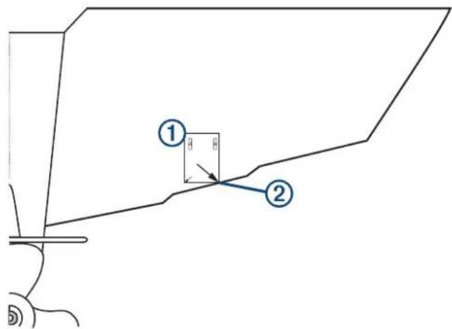
3 Mark the center location of the two holes of the template.
4 Remove the template from the transom.
5 Wrap a piece of tape around a 4 mm ( 5/32 in.) bit at 18 mm ( 7/10 in.) from the point of the bit, to avoid drilling the pilot holes too deep.
6 If you are installing the bracket on fiberglass, place a piece of tape over the pilot-hole location to reduce cracking of the gel coat.
7 Using the 4 mm ( 5/32 in.) bit, drill the pilot holes approximately 18 mm ( 7/10 in.) deep at the marked locations.
8 Apply marine sealant to the included 20 mm screws, and attach the transducer assembly to the transom.
9 Route the cable under the transom mount cable hook.

natural_image
Technical line drawing of a mechanical component with no visible text or symbols10 If you must route the cable through the transom, choose a pilot-hole location well above the waterline and mark it.
11 Place a cable clamp on the transducer cable, approximately halfway between the transducer and the top of the transom or the pass-through pilot hole.
12 Mark the pilot-hole location for the cable clamp, and using a 3.2 mm ( 1/8 in.) bit, drill a pilot hole approximately 10 mm ( 3/8 in.) deep.
13 Apply marine sealant to the included 12 mm screw, and attach the cable clamp to the transom.
14 If you marked a pilot hole in step 7, choose the appropriate drill bit to drill a pass-through hole completely through the transom:
- If you have the 4-pin cable, use a 16mm ( 5/8 in.) drill bit.
- If you have the 8-pin or 12-pin cable, use a 25mm (1 in.) drill bit.
15 Route the transducer cable to the sounder:
- If you are routing the cable using a pass-through hole, push it through the pass-through hole, and install the cable-entry cover (Installing the Cable-Entry Cover, page 5).
- If you are not routing the cable using a pass-through hole, route the cable up and over the top of the transom.
You should avoid routing the cable close to electrical wires or other sources of electrical interference.
Installing the Cable-Entry Cover
If you routed the cable through the transom after you installed the transducer, you should install the cable-entry cover to keep water from entering your boat.
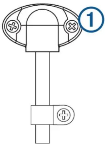
1 Place the cable-entry cover ① over the hole and the cable, with the opening pointing downward, and mark the location of the two pilot holes.
natural_image
Pure electrical circuit lines without any symbols2 Remove the cable-entry cover, and, using a 3.2 mm ( 1/8 in.) bit, drill the pilot holes approximately 10 mm ( 3/8 in.) deep.
3 Fill the pass-through hole with marine sealant so it covers the cable completely and there is excess sealant around the hole and the cable.
4 Place the cable-entry cover over the hole and the cable, with the opening pointing downward.
5 Apply marine sealant to the included 12 mm M4 screws, and attach the cable-entry cover to the transom.
6 Wipe away all excess marine sealant.
Testing the Installation
NOTICE
You should check your boat for leaks before you leave it in the water for an extended period of time.
Because water is necessary to carry the sonar signal, the transducer must be in the water to work properly. You cannot get a depth or distance reading when out of the water. When you place your boat in the water, check for leaks around any screw holes that were added below the water line.
Testing the Transom-Mount Transducer Installation
NOTICE
When adjusting the depth of the transducer, make the adjustments in small increments. Placing the transducer too deep can adversely affect the performance of the boat and put the transducer at risk of striking underwater objects.
Test the transom-mount transducer installation in open water free of obstacles. Pay attention to your surroundings as you test the transducer.
1 With the boat in the water, turn on the chartplotter.
2 Drive the boat at a slow speed. If the chartplotter appears to be working properly, gradually increase speed while observing the chartplotter.
3 If the sonar signal is suddenly lost or the bottom return is severely degraded, note the speed at which this occurs.
4 Return the boat to the speed at which the signal was lost, and make moderate turns in both directions while observing the chartplotter.
5 If the signal strength improves while turning, adjust the transducer so that it extends another 18 in. (3 mm) below the transom of the boat.
6 Repeat steps 2–4 until the degradation is eliminated.
7 If the signal does not improve, move the transducer to a different location on the transom, and repeat the test.
Installing the Transducer on a Trolling Motor
Assembling the Trolling Motor Mount
1 Using the 8 mm M4 screws and 4 mm star washers, attach the trolling motor mount to the transducer ④

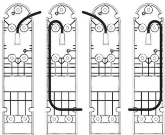
2 Before tightening the screws, route the cable inside the mount to a cable exit.
The trolling motor mount is designed with multiple cable exits. You should use a cable exit that allows the cable to be on the top side of the trolling motor housing when the motor is stowed. See the image below for recommended cable routes.
natural_image
Four identical line drawings of a double bass with internal circuitry and wiring, no text or symbols present.You must avoid pinching the cable or bending it too tightly.
Attaching the Transducer to the Trolling Motor
NOTICE
Do not cut the transducer cable. Cutting the transducer cable will void your warranty.
1 Insert the hose clamps ① through the slots on the transducer mount ②, until equal lengths extend on both sides of the mount.

2 Place the transducer mount against the body of the trolling motor with the narrow end of the transducer pointed away from the propeller.
3 Secure the hose clamps around the body of the trolling motor, and tighten the hose clamps.
4 Position the transducer so it is parallel to the bottom when in use.
5 Use waterproof tape (not included) to secure the transducer cable to the trolling motor shaft.
6 Route the transducer cable to the installation location of the chartplotter while taking these precautions.
- You should avoid routing the cable close to electrical wires or other sources of electrical interference.
- You must avoid routing the cable where it is pinched when the trolling motor is deployed or stowed.
Software Update
You must update the Garmin chartplotter software when you install this device. For instructions on updating the software, see your chartplotter owner's manual at support.garmin.com.
Contacting Garmin Support
- Go to support.garmin.com for help and information, such as product manuals, frequently asked questions, videos, and customer support.
• In the USA, call 913-397-8200 or 1-800-800-1020.
• In the UK, call 0808 238 0000.
• In Europe, call +44 (0) 870 850 1241.
© 2017 Garmin Ltd. or its subsidiaries
Garmin 1 and the Garmin logo are trademarks of Garmin Ltd. or its subsidiaries, registered in the USA and other countries. These trademarks may not be used without the express permission of Garmin.
Windows ® is a registered trademark of Microsoft Corporation in the United States and other countries.



- Garmin ClearVü™ Transducer Transom/Trolling Motor Mount
- Important Safety Information
- WARNING
- CAUTION
- NOTICE
- Tools Needed
- Transom mount
- Trolling motor mount
- Preparing the Transducer for Long-Term Exposure to Water
- Mounting Consideration
- Installing the Transducer on a Transom
- Mounting Location Considerations
- Assembling the Transducer with a Transom Mount Bracket
- Installing the Transom-Mount Hardware
- Installing the Cable-Entry Cover
- Testing the Installation
- Testing the Transom-Mount Transducer Installation
- Installing the Transducer on a Trolling Motor
- Assembling the Trolling Motor Mount
- Attaching the Transducer to the Trolling Motor
- Software Update
- Contacting Garmin Support
Brand : GARMIN
Model : GT20-TM
Category : Sonar