
Vieo RV 51 Stereo Dock - Audio accessory GARMIN - Free user manual and instructions
Find the device manual for free Vieo RV 51 Stereo Dock GARMIN in PDF.


| Product Type | Audio Docking Station |
| Brand | Garmin |
| Model | Vieo RV 51 Stereo Dock |
| Compatible Devices | Garmin Vieo RV 51 GPS Navigator |
| Speaker Configuration | Built-in stereo speakers, 2 x 3W RMS |
| Audio Input | 3.5mm AUX, Bluetooth (A2DP) |
| Power Input | 12V DC from vehicle power (cigarette lighter) |
| Power Output (charging) | 5V DC, 2A via USB for connected device |
| Dimensions (W x H x D) | 180 x 120 x 80 mm |
| Weight | 320 g |
| Mounting Type | Dashboard or windshield suction cup (included) |
| Bluetooth Version | 4.0 |
| Wi-Fi | Not supported |
| Controls | Volume up/down, play/pause, track skip, power |
| Indicators | Power LED, Bluetooth pairing LED |
| Cable Length (power) | 1.5 m |
| Operating Temperature | 0°C to 60°C |
| Storage Temperature | -20°C to 70°C |
| Material | Plastic (ABS), silicone rubber grip |
| Cleaning Instructions | Wipe with a soft, dry cloth. Avoid solvents. |
| Safety Certifications | CE, FCC, RoHS |
| Warranty | 1 year limited |
| Included Accessories | Vehicle power cable, suction cup mount, user manual |
Frequently Asked Questions - Vieo RV 51 Stereo Dock GARMIN
User questions about Vieo RV 51 Stereo Dock GARMIN
0 question about this device. Answer the ones you know or ask your own.
Ask a new question about this device
Download the instructions for your Audio accessory in PDF format for free! Find your manual Vieo RV 51 Stereo Dock - GARMIN and take your electronic device back in hand. On this page are published all the documents necessary for the use of your device. Vieo RV 51 Stereo Dock by GARMIN.
USER MANUAL Vieo RV 51 Stereo Dock GARMIN
See the Important Safety and Product Information guide in the product box for product warnings and other important information.
CAUTION
Failure to follow these cautions could result in damage to the vehicle or poor product performance.
This device must be installed according to these instructions.
Disconnect the vehicle's power supply before beginning to install this product.
Before applying power to this product, make sure it has been correctly grounded according to the installation instructions.
You must read all installation instructions before beginning the installation. If you experience difficulty during the installation, contact Garmin® Product Support.
Connector Identification
Connector Identification (Vieo RV 5I)
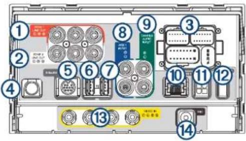
| Item | Label Description | Connector Details | |
| 1 | ZONE 1 LINE OUT | Line out connectors for zone 1 | Left (white), right (red), and subwoofer (orange) RCA connectors |
| 2 | ZONE 2 LINE OUT | Line out connectors for zone 2 | Left (white), right (red), and subwoofer (orange) RCA connectors |
| 3 | None | Wiring harness connectors | Connects to the included and optional wiring harnesses |
| 4 | None | AM/FM antenna connector | Connects to either the vehicle's AM/FM antenna cable or an inline adapter attached to the vehicle's AM/ FM antenna cable |
| 5 | SiriusXM SiriusXM | ^ port | Connects to a compatible SiriusXM Connect vehicle tuner and antenna (sold separately) |
| 6 |  | USB (500 mA) | Reserved for manufacturer use Compatible only with low-current (<500 mA) USB devices |
| 7 | iPhone/iPod USB (1 A) | Interfaces with and charges supported smartphones and USB devices | |
| 8 | AUX 1 INPUT Auxiliary input 1 Left (white) and right (red) RCA connectors | ||
| 9 | CAMERA AUDIO INPUT | Input for camera audio Left (white) and right (red) RCA connectors | |
| 10 | None RJ-45 Supports Ethernet connectivity | ||
| 11 | CAN 1 CAN BUS 1 | Connects to RV control systems using an adapter (sold separately) | |
| 12 | CAN 2 CAN BUS 2 | Reserved for vehicle integration Connects to supported chassis CAN systems using an adapter cable to support steering wheel controls | |
| 13 | VIDEO IN | Analog camera video input | 4 RCA video connectors Connects to up to four vehicle cameras, including forward, left view, right view, and backup cameras |
| 14 | MIC Microphone input | 3.5 mm mono microphone port Connects to the included microphone for hands-free calling | |
Connector Identification (Vieo RV 52)
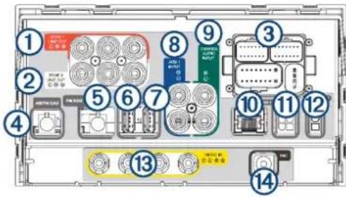
| Item | Label Description | Connector Details | |
| 1 | ZONE 1 LINE OUT | Line out connectors for zone 1 | Left (white), right (red), and subwoofer (orange) RCA connectors |
| 2 | ZONE 2 LINE OUT | Line out connectors for zone 2 | Left (white), right (red), and subwoofer (orange) RCA connectors |
| 3 | None | Wiring harness connectors | Connects to the included, optional wiring harnesses |
| 4 | AM/FM/DAB | AM/FM/DAB connector (default source) | Connects to a compatible antenna. Must be used for AM band (default) |
| 5 | FM/DAB | Connector for alternate FM, FM and DAB, or DAB antenna | Connects to a dedicated FM, FM and DAB, or DAB antenna if reception is not covered by the AM/FM/DAB antenna (requires menu reconfiguration) |
| 6 |  | USB (500 mA) | Reserved for manufacturer useCompatible only with low-current (<500 mA) USB devices |
| 7 | iPhone/iPod USB (1 A) | Interfaces with and charges supported smartphones and USB devices | |
| 8 | AUX 1 INPUT Auxiliary input 1 Left (white) and right (red) RCA connectors | ||
| 9 | CAMERA AUDIO INPUT | Input for camera audio Left (white) and right (red) RCA connectors | |
| 10 | None RJ-45 Supports Ethernet connectivity | ||
| 11 | CAN 1 CAN BUS 1 | Connects to RV control systems using an adapter (sold separately) | |
| 12 | CAN 2 CAN BUS 2 | Reserved for vehicle integrationConnects to supported chassis CAN systems using an adapter cable to support steering wheel controls | |
| 13 | VIDEO IN | Analog camera video input | 4 RCA video connectorsConnects to up to four vehicle cameras, including forward, left view, right view, and backup cameras |
| 14 | MIC Microphone input | 3.5 mm mono microphone portConnects to the included microphone for hands-free calling | |
Wiring Harnesses
Power and Speaker Wiring Harness
The power and speaker wiring harness contains the main power and speaker connections for the system. The harness connects directly to the stereo and to the vehicle wiring harness without modification. You can use this diagram to troubleshoot or to address non-default installation requirements. Wiring harnesses may vary based on installation requirements.

natural_image
Technical line drawing of a mechanical component with labeled parts (1 and 2), no readable text or symbols present.| Wire Color Function Notes | ||
| Yellow Power (+) | Connects to the positive terminal of a 12 Vdc power source capable of supplying 15 A. | |
| Red Ignition | Connects to a separately-switched, 12 Vdc connection, such as an ignition bus, to turn the stereo on. | |
| Orange None Reserved for future use. | ||
| Black Ground (-) | Connects to the negative terminal of a 12 Vdc power source capable of supplying 15 A. You should connect this wire before connecting the yellow wire. All accessories connected to the stereo must share a common ground location. | |
| Blue Amplifier on | Connects to optional external amplifiers, enabling them to turn on when the stereo turns on. | |
| Brown None Reserved for future use. | ||
| Pink Reverse | Connects to an analog high signal, such as the reverse light, to activate the backup camera when the vehicle is placed in reverse. | |
| Red/black House | Connects to a 12 Vdc connection for the RV house power to turn the stereo on when the house power is turned on. | |
| White Speaker zone 1 left (+) | ||
| White/black Speaker zone 1 left (-) | ||
| Gray Speaker zone 1 right (+) | ||
| Gray/black Speaker zone 1 right (-) | ||
| Green Speaker zone 2 left (+) | ||
| Green/black | Speaker zone 2 left (-) | |
| Purple Speaker zone 2 right (+) | ||
| Purple/black | Speaker zone 2 right (-) | |
Freightliner® Power and Speaker Wiring Harness
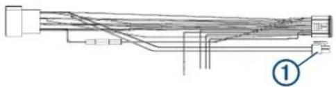
The Freightliner power and speaker wiring harness connects directly to the CAN bus 2.0 system ⑩ support steering wheel controls. This wiring harness is available for the Freightliner M2 and Cascadia vehicles.
natural_image
Pure electrical circuit lines without any symbolsLine Out Wiring Harness
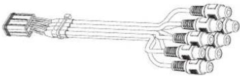
The line out wiring harness (sold separately) outputs audio to an external amplifier for zones 3 and 4.
natural_image
Diagram of a multi-pin electrical connector with multiple leads (no text or symbols)| Label Function RCA connectors | ||
| ZONE 3 Outputs analog audio to an external amplifier for zone 3. | Left (white), right (red), and sub (orange) | |
| ZONE 4 Outputs analog audio to an external amplifier for zone 4. | Left (white), right (red), and sub (orange) | |
| AUX IN 2 | Not used. These connectors are not active for the Vioo RV 51/52 product model. You must use the CAMERA AUDIO INPUT connector on the back of the stereo instead. | Not used |
Analog Signal Wiring Harness
| Wire color | Pin | Function Notes | |
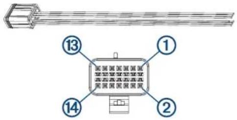
| Green 1 | Analog input 1 | Connects to the steering wheel controls. Not available for all vehicles. Contact the RV manufacturer for more information. | |
| Purple 2 | Analog input 2 | Connects to the steering wheel controls. Not available for all vehicles. Contact the RV manufacturer for more information. | |
| Black 4 | Analog input ground Ground wire for analog steering wheel control inputs. | ||
| Orange 5 | Right camera trigger | Connects to an analog high signal, such as the right turn signal, to trigger the device to display the right side camera. | |
| Blue 6 | Left camera trigger | Connects to an analog high signal, such as the left turn signal, to trigger the device to display the left side camera. | |
| Brown 7 | Front camera trigger | Connects to an analog high signal to trigger the device to display the front camera. | |
| Black 9 | Camera trigger ground | Ground wire for the camera trigger inputs. | |
Connecting Vehicle and Backup Cameras
You can connect up to four analog vehicle cameras to the infotainment system for backup, left, right, and front cameras.
1 For each camera, route the camera's RCA analog video cable to the back of the stereo.
You should clearly label each cable for reference when you are connecting them to the stereo.
2 For each camera, determine the analog high signal that should trigger the stereo to display the camera, and route a wire for that signal to the back of the stereo.
For example, you can use a reverse signal to trigger the backup camera when the vehicle is put in reverse, or you can use turn signal to trigger a side mirror camera.
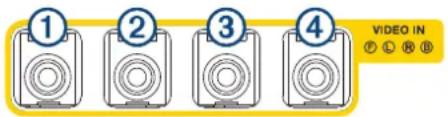
3 Connect each RCA analog video cable to the VIDEO IN connectors on the back of the stereo, as shown.
①
Front camera
②
Left camera
③
Right camera
④
Backup camera
4 Connect the analog high signal wire for the backup camera to the pink REVERSE wire of the power and speaker wiring harness (Power and Speaker Wiring Harness, page 4).
5 Connect the analog high signal wire for each of the other cameras to the appropriate camera detect wire of the analog signal detect harness (Analog Signal Wiring Harness, page 6).
NOTE: If you do not want to trigger a camera automatically, you should leave that camera detect wire disconnected.
| Harness wire color Camera | |
| Blue Left camera | |
| Orange Right camera | |
| Brown Front camera | |
Attaching the Display Adapter to the Dock (7-inch Models Only)
You should attach the adapter to the dock before you install the dock in a dashboard.
1 Place the adapter ① on the front of the dock, aligning the four screw holes on the adapter with the dock.
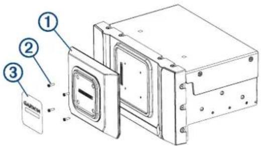
2 Using the included screws ③ secure the adapter to the dock.
The recommended torque applied to the adapter screws is 3.0 to 3.5 lbf-in. (0.34 to 0.40 N-m).
3 Adhere the adapter label to the front of the adapter.
Dock Installation
You must use the appropriate fit kit (sold separately) to install the device dock into a specific vehicle type. Each fit kit includes the hardware required to attach the mounting brackets to the dock. The product package does not include the hardware to attach the bracket to the dashboard or the dashboard panel.
Installing the Bracket on the Dock for Mercedes-Benz ^® Sprinter ^™ Vehicles
1 Place each bracket ① on the dock, aligning the holes on the bracket with the holes on the dock.
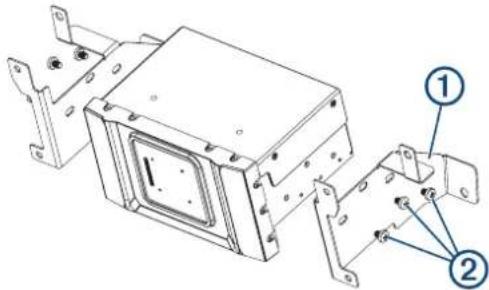
2 Using the included screws , secure each bracket to the dock.
The recommended torque you should apply to the screws is 5.0 to 6.0 lbf-in. (0.56 to 0.68 N-m).
3 Install the dock into the dashboard using the appropriate hardware (not included).
4 Attach the included bezel to the front of the dock.
5 If necessary, install all remaining dashboard components.
Installing the Bracket on the Dock for Freightliner M2 Vehicles
1 Place each bracket ① on the dock, aligning the holes on the bracket with the holes on the dock.
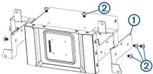
2 Using the included screws ,③ secure each bracket to the dock.
The recommended torque you should apply to the screws is 5.0 to 6.0 lbf-in. (0.56 to 0.68 N-m).
3 Install the dock into the dashboard using the appropriate hardware (not included).
4 Attach the included bezel to the front of the dock.
5 If necessary, install all remaining dashboard components.
Installing the Bracket on the Dock for IVECO™ Vehicles
1 Place each bracket ① on the dock ②, aligning the holes on the bracket with the holes on the sides of the dock.
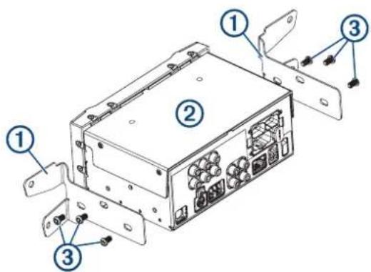
2 Using the included screws , secure each bracket to the sides of the dock.
The recommended torque you should apply to the screws is 5.0 to 6.0 lbf-in. (0.56 to 0.68 N-m).
3 Attach the bracket and dock to the dashboard using the appropriate hardware (not included).
4 Attach the included bezel to the front of the dock.
5 If necessary, install all remaining dashboard components.
Installing the Bracket for FIAT™ Ducato Vehicles
1 Place the upper bracket ① on the dock ②, aligning the holes in the bracket with the holes on the top of the dock.
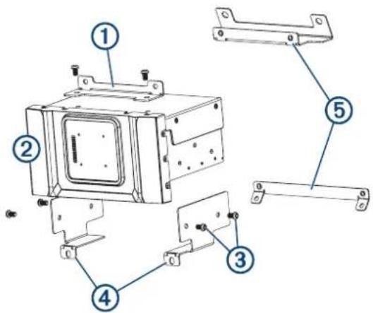
2 Using the included screws , secure the bracket to the top of the dock.
The recommended torque you should apply to the screws is 5.0 to 6.0 lbf-in. (0.56 to 0.68 N-m).
3 Repeat this procedure for the side brackets ④
4 Install the upper and lower chassis brackets onto the dashboard.
5 Install the dock onto the dashboard using the appropriate hardware.
6 Attach the included bezel to the front of the dock.
7 If necessary, install all remaining dashboard components.
Freightliner Cascadia Installation
You can install the device in two possible locations on the Freightliner Cascadia dashboard.
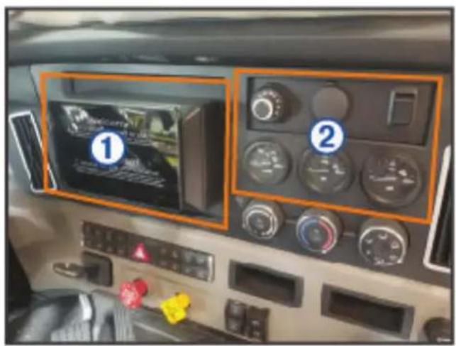
① Left center panel (Installing the Device in the Left Center Panel, page 11)
② Right single DIN panel and gauge area (Installing the Device in the Right Single DIN Panel and Gauge Area, page 13)
Installing the Device in the Left Center Panel
You can use the included hardware to flush mount the device in the left center panel opening on a Freightliner Cascadia vehicle.
1 Remove the dashboard front panel.
2 Secure the mount plate to the dashboard using the four screws from the vehicle compartment.
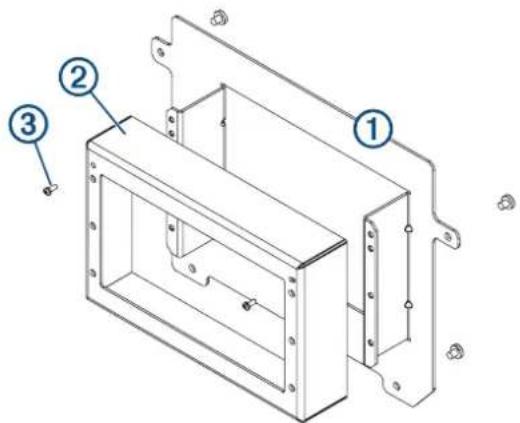
3 Secure the mount cover to the mount plate using two of the included M3 screws. ③
4 Replace the dashboard front panel.
5 Place each bracket ④ on the dock ⑤, aligning the holes in the bracket with the holes on the dock.
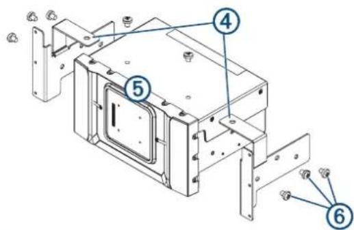
6 Using the included M5 screws , secure each bracket to the dock.
You should apply a recommended torque of 5.0 to 6.0 lbf-in. (0.56 to 0.68 N-m) to the screws.
7 Connect all necessary cables to the device before placing it into the mount.
8 Place the device into the mount.
9 Secure the brackets to the mount cover using the included M3 screws.⑦
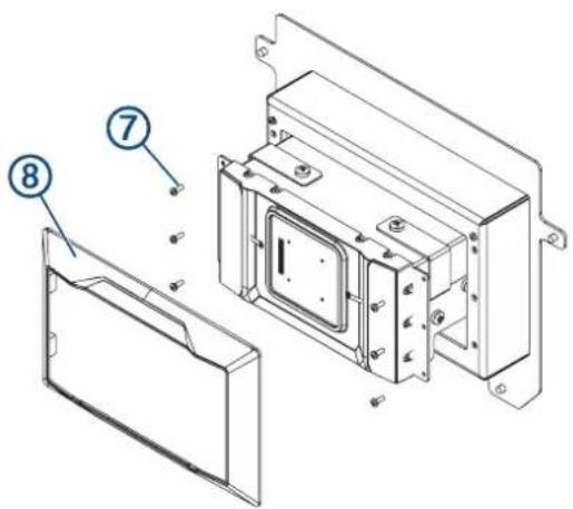
10 Install the decorative bezel by snapping it in place around the edges of the device.
Installing the Device in the Right Single DIN Panel and Gauge Area
You can use the included template and hardware to flush mount the device in the single DIN panel and gauge area with dashboard modifications.
NOTICE
Avoid wires, gauges, air bags, air bag covers, HVAC, and other items when cutting the dashboard and attaching the mount to the vehicle. Garmin is not responsible for any damages or consequences arising from the installation.
1 Place each bracket ① on the dock ②, aligning the holes in the bracket with the holes on the dock.
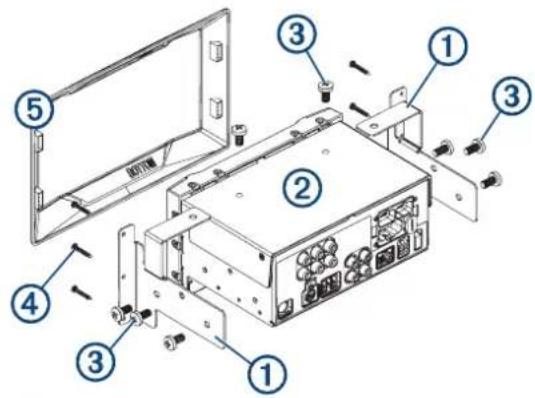
2 Using the included M5 screws , secure each bracket to the dock.
You should apply a recommended torque of 5.0 to 6.0 lbf-in. (0.56 to 0.68 N-m) to the screws.
3 Remove the dashboard front panel.
4 Trim the mounting template, and confirm the device will fit in the mounting location.
5 Secure the template to the mounting location.
6 Using a jigsaw or rotary tool, cut the mounting surface along the dashed line on the template.
7 Place the device in the cutout to test the fit.
8 If necessary, refine the size of the cutout and remove extra material from the inside of the dashboard.
9 After the device fits correctly in the cutout, verify the mounting holes on the device line up with the pilot holes on the template.
10 If the mounting holes on the device do not line up, mark the new pilot-hole locations.
11 Using a 1.5 mm (#53) drill bit, drill the pilot holes.
12 Remove the template from the mounting surface.
13 Install the support bracket at the base of the cutout in the dashboard (not included).
14 Replace the dashboard front panel.
15 Connect all necessary cables to the device before placing it into the cutout.
16 Place the device into the cutout.
17 Secure the device to the mounting surface using the included M3 screws④
18 Install the decorative bezel by snapping it in place around the edges of the device.
Installing the Device in a Dodge ProMaster
1 Place the upper bracket ① on the dock ②, aligning the holes in the bracket with the holes on the top of the dock.
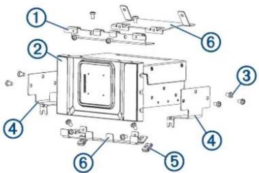
2 Using the included screws , secure the bracket to the top of the dock.
The recommended torque you should apply to the screws is 5.0 to 6.0 lbf-in. (0.56 to 0.68 N-m).
3 Repeat this procedure for the side brackets ④
4 Attach the clip-on nuts ⑤ to the bottom edge of the dashboard, and attach the chassis bracket ⑥ to the clip-on nuts using the included screws.
5 Attach the upper chassis bracket ⑥ to the dashboard using the existing screws in the vehicle dashboard.
6 Attach the dock to the dashboard using the included screws.
7 Attach the included bezel to the front of the dock.
8 If necessary, install all remaining dashboard components.
Installing the Device on a Wall
The included template and hardware can be used to flush mount the device on the wall in your recreational vehicle.
WARNING
Always be sure of your mounting location before cutting into a wall. Recreational vehicle walls may contain utility lines. Failure to understand what is behind your mounting surface could result in damage to the vehicle, injury, or death.
NOTICE
Wall-mount kits are intended for wall-mount installations only. Do not attempt to install this device in a vehicle dashboard using a wall-mount kit.
The wall-mount bracket includes the hardware required to attach the dock to a wooden surface. If you are mounting the device on a different material, you should use suitable hardware for your mounting surface.
1 Place each bracket ① on the dock ②, aligning the holes in the bracket with the holes on the dock.
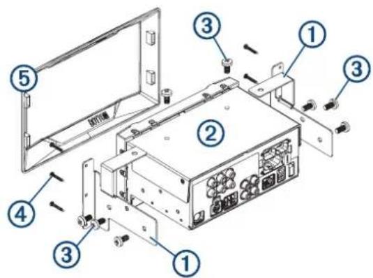
2 Using the included M5 screws, secure each bracket to the dock.
The recommended torque you should apply to the screws is 5.0 to 6.0 lbf-in. (0.56 to 0.68 N-m).
3 Trim the template, and confirm the device will fit in the location where you want to mount it.
4 Secure the template to the mounting location.
5 Using a jigsaw or rotary tool, cut the mounting surface along the dashed line on the template.
6 Place the device in the cutout to test the fit.
7 If necessary, refine the size of the cutout.
8 After the device fits correctly in the cutout, verify the mounting holes on the device line up with the pilot holes on the template.
9 If the mounting holes on the device do not line up, mark the new pilot-hole locations.
10 Using a 1.5 mm (#53) drill bit, drill the pilot holes.
11 Remove the template from the mounting surface.
12 If you will not have access to the back of the device after you mount it, connect all necessary cables to the device before placing it into the cutout.
13 Place the device into the cutout.
14 Secure the device to the mounting surface using the included M3 screws ④.
15 Install the decorative bezel ⑤ by snapping it in place around the edges of the device.
Stereo Information
Specifications
| Display Specifications | |
| Operating temperature range From -20 to 55°C (from -4 to 131°F) | |
| Charging temperature range From 0 to 45°C (from 32 to 113°F) | |
| Wireless frequency/protocol 2.4 GHz @ 15 dBm nominal | |
| Power input | Vehicle power using the included vehicle power cable. AC power using an optional accessory (for home and office use only). |
| Battery type Rechargeable lithium-ion | |
| Dock Specifications | |
| Operating temperature range From -10 to 55°C (from 14 to 131°F) | |
| Storage temperature range From -20 to 70°C (from -4 to 158°F) | |
| Input voltage From 10.8 to 16 Vdc | |
| Current (max.) 15 A | |
| Current (standby mode) Less than 5 mA | |
| Fuse 15 A mini blade type | |
| Wireless frequency/protocol 2.4 GHz @ 7.9 dBm nominal | |
| On-board, Class D Amplifier | |
| Output music power per channel 4 x 70 W max. 2 ohm | |
| Total output peak power 280 W max. | |
| Output power per channel | 4 x 43 W RMS at 14.4 Vdc input, 2 ohm, 10% THD ^1 4 x 26 W RMS at 14.4 Vdc input, 4 ohm, 10% THD ^1 |
| Line output level (max.) 5.5 V (peak to peak) | |
| Aux. input level (typical) 1 V RMS | |
| Tuner Europe and Australasia | USA | |
| FM radio frequency range | 87.5 to 108 MHz | 87.5 to 107.9 MHz |
| FM frequency step | 50 kHz | 200 kHz |
| AM radio frequency range | 522 to 1620 kHz | 530 to 1710 kHz |
| AM frequency step | 9 kHz | 10 kHz |
© 2020 Garmin Ltd. or its subsidiaries
Garmin ^® , the Garmin logo, Fusion ^® , and the Fusion logo are trademarks of Garmin Ltd. or its subsidiaries, registered in the USA and other countries. Vioo ^™ is a trademark of Garmin Ltd. or its subsidiaries. These trademarks may not be used without the express permission of Garmin.
Android ^™ is a trademark of Google Inc. Apple ^® , the Apple logo, iPod ^™ , iPhone ^® , and Mac ^™ are trademarks of Apple Inc., registered in the U.S. and other countries. Bluetooth ^® word mark and logos are owned by the Bluetooth SIG, Inc. and any use of such marks by Garmin is under license. Dodge is a registered trademark of FCA US LLC. Freightliner ^® , Mercedes-Benz ^® , and Sprinter ^™ are registered trademarks of Daimler AG. FIAT ^™ is a trademark of FCA Group Marketing S.P.A. Corporation Italy. IVECO ^™ is a trademark of IVECO S.P.A. LLC, Turin, Italy. microSD ^™ and the microSDHC logo are trademarks of SD-3C, LLC. SiriusXM ^® is a registered trademark of SiriusXM Radio Inc. Wi-Fi ^® is a registered trademark of Wi-Fi Alliance Corporation.
- CAUTION
- Connector Identification
- Connector Identification (Vieo RV 5I)
- Connector Identification (Vieo RV 52)
- Wiring Harnesses
- Power and Speaker Wiring Harness
- Freightliner® Power and Speaker Wiring Harness
- Line Out Wiring Harness
- Analog Signal Wiring Harness
- Connecting Vehicle and Backup Cameras
- Attaching the Display Adapter to the Dock (7-inch Models Only)
- Dock Installation
- Installing the Bracket on the Dock for Mercedes-Benz ® Sprinter ™ Vehicles
- Installing the Bracket on the Dock for Freightliner M2 Vehicles
- Installing the Bracket on the Dock for IVECO™ Vehicles
- Installing the Bracket for FIAT™ Ducato Vehicles
- Freightliner Cascadia Installation
- Installing the Device in the Left Center Panel
- Installing the Device in the Right Single DIN Panel and Gauge Area
- NOTICE
- Installing the Device in a Dodge ProMaster
- Installing the Device on a Wall
- WARNING
- Stereo Information
Brand : GARMIN
Model : Vieo RV 51 Stereo Dock
Category : Audio accessory