
H80CIMS-ADR - Ice Maker Perlick - Free user manual and instructions
Find the device manual for free H80CIMS-ADR Perlick in PDF.


| Product Type | Residential Undercounter Ice Maker |
| Model | H80CIMS-ADR (ADA Compliant) |
| Ice Style | Cubelet |
| Dimensions (H x W x D) | 32" x 15" x 24" (814 x 381 x 610 mm) minimum niche, product slightly smaller |
| Electrical Supply | 115-120V, 60 Hz, 1 Phase, NEMA 5-15P plug with 6 ft cord |
| Refrigerant | R134a, 3.92 oz |
| Design Pressure | HI 240 PSI, LO 120 PSI |
| Water Supply Pressure | 7 to 113 PSIG |
| Ambient Temperature Range | 45°F to 100°F (7°C to 38°C) |
| Water Temperature Range | 45°F to 90°F (7°C to 32°C) |
| Ice Production Capacity | Not specified in manual; typical for cubelet undercounter ~25-50 lbs/day |
| Storage Bin Capacity | Not specified; typical ~20-30 lbs |
| Installation Clearance | No side/top clearance required; 15" (38 cm) front clearance for service |
| Door Hinge Reversible | Yes, using kit 70084 |
| Overlay Panel Compatible | Yes, max weight 20 lb (9 kg), thickness 5/8"-3/4" |
| Drain Type | Gravity drain (1/2" ID hard pipe) or optional drain pump 63802A |
| Maintenance Frequency | Clean and sanitize at least twice a year; quarterly bin drain; annual condenser cleaning |
| Safety Features | 3-prong grounded plug, bin control thermostat, overheat protection, child safety warnings |
| Included Accessories | Plastic ice scoop, overlay panel hardware kit |
| Optional Accessories | Drain pump (63802A), hinge reversal kit (70084) |
| Manufacturer | Perlick Residential, Milwaukee, WI, USA |
| Warranty | Registration required at perlick.com/RegisterMyPerlick |
Frequently Asked Questions - H80CIMS-ADR Perlick
User questions about H80CIMS-ADR Perlick
0 question about this device. Answer the ones you know or ask your own.
Ask a new question about this device
Download the instructions for your Ice Maker in PDF format for free! Find your manual H80CIMS-ADR - Perlick and take your electronic device back in hand. On this page are published all the documents necessary for the use of your device. H80CIMS-ADR by Perlick.
USER MANUAL H80CIMS-ADR Perlick
H80CIM/-AD PRODUCT MANUAL
natural_image
Black-and-white photo collage showing ice cubes, a refrigerator, and a glass of ice with water (no text or symbols visible)PERLICK RESIDENTIAL UNDERCOUNTER ICE MAKERS
To prevent appliance damage and injury, read these instructions thoroughly prior to installation.
H80CIM* 15" SIGNATURE SERIES CUBELET ICE MAKER H80CIM*-AD 15" ADA COMPLIANT CUBELET ICE MAKER
CONTENTS
3 Safety Considerations
5 Prior To Installation
6 Niche / Product Dimensions / Connections
10 Construction
11 Electrical / Refrigerant
12 Installation Instructions
20 Setup
21 Electrical Connection
22 Water Supply And Drain Connections
23 Final Checklist
24 Operating Instructions
25 Startup
26 Maintenance
32 Preparing The Appliance For Periods Of Non-Use
33 Disposal
INTRODUCTION
Congratulations on your purchase of a Perlick Residential undercounter appliance. This manual has been prepared to assist you in the installation of your undercounter ice maker.
We dedicate considerable time to ensure that our products provide the highest level of customer satisfaction. We thank you for selecting Perlick products for your home and assure you of our continuing interest in your satisfaction.
WARRANTY REGISTRATION
To register your Perlick product, visit our website at
www.perlick.com/RegisterMyPerlick and fill out the form.
Once completed, click on the 'Submit Warranty Registration'. Be sure to register your product immediately upon installation to receive the warranty from installation date instead of shipment date. If left blank, the date will revert back to shipment date.
SAFETY CONSIDERATIONS
IMPORTANT SAFETY INFORMATION
This manual should be read carefully before the ice maker is installed and operated. Only qualified service technicians should install, service, and maintain the ice maker. Read the warnings contained in this booklet carefully as they give important information regarding safety. Please retain this booklet for any further reference that may be necessary.
DAMANGERicates that a hazardous situation
may occur when instructions are not followed. It is imperative that directions in this guide are followed to prevent possible serious injury or death.
WARNING: a situation where minor
injury, product or cabinet damage may occur if the following instructions are not followed.
This highlights information that is of significant importance.
▲ DANGER This ice maker should be destined only to the use for which it has been expressly conceived. Any other use should be considered improper and therefore dangerous. The manufacturer cannot be held responsible for eventual damage caused by improper, incorrect, and unreasonable use. To reduce the risk of death, electric shock, serious injury, or fire, follow basic precautions including the following:
DANGER service technicians should install and service the appliance.
⚠️ DANGER must be installed in accordance with applicable national, state, and local codes and regulations.
▲ DANGER requires an independent power supply of proper capacity. See the nameplate for electrical specifications. Failure to use an independent power supply of proper capacity can result in a tripped breaker, blown fuse, damage to existing wiring, or component failure. This could lead to heat generation or fire.
DANGER E MUST BE GROUNDED:
The appliance is equipped with a NEMA 5-15 three-prong grounding plug to reduce the risk of potential shock hazards. It must be plugged into a properly grounded, independent 3-prong wall outlet. If the outlet is a 2-prong outlet, it is your personal responsibility to have a qualified electrician replace it with a properly grounded, independent 3-prong wall outlet. Do not remove the ground prong from the power cord and do not use an adapter plug. Failure to properly ground the appliance could result in death or serious injury.
DANGER extension cord.
⚠️ DANGER risk of electric shock, do not touch the control switch or plug with damp hands. Make sure the control switch is in the “OFF” position before plugging in or unplugging the appliance.
⚠️ DANGER appliance with a damaged power cord. The power cord should not be altered, jerked, bundled, weighed down, pinched, or tangled. Such actions could result in electric shock or fire. To unplug the appliance, be sure to pull the plug, not the cord, and do not jerk the cord.
▲ DANGER Any alterations to the appliance. Alterations could result in electric shock, injury, fire, or damage to the appliance.
DANGER ngers or any other objects into the ice discharge opening.
SAFETY CONSIDERATIONS
⚠️ DANGER is not intended for use by
persons (including children) with reduced physical, sensory, or mental capabilities, or lack of experience and knowledge, unless they have been given supervision or instruction concerning use of the appliance by a person responsible for their safety.
▲ DANGER should be properly
supervised around the appliance.
▲ DANGER stand, or hang on the
appliance or appliance door or allow children or animals to do so. Serious injury could occur or the appliance could be damaged.
DANGER to pinch fingers when
opening and closing the door. Be careful when opening and closing the door when children are in the area.
A DANGER Humbustible spray or place
volatile or flammable substances near the appliance. They might catch fire.
▲ DANGER around the appliance clean.
Dirt, dust, or insects in the appliance could cause harm to individuals or damage to the appliance.
PRIOR TO INSTALLATION
WARNING floor when moving the appliance to prevent damage to the floor.
WARNING water supply, drain connection, and maintenance instructions carefully to reduce the risk of costly water damage.
I WARNING re water damage is a concern, install in a contained area with a floor drain.
WARNING:pliance in a location that stays above freezing. Normal operating ambient temperature must be within 45°F to 100°F (7°C to 38°C).
WARNING optional drain pump (63802A), test its operation every time the appliance is cleaned and sanitized. See Optional Drain Pump 63802A (pg 31) for details. If the optional drain pump is not operating properly, water could back up and overflow, leading to costly water damage.
WARNINGre the storage bin drain remains clear, follow the instructions in Storage Bin Drain (pg 30) once every 3 months or as often as necessary for conditions. If the storage bin drain becomes clogged, water could build up in the bin and overflow, leading to costly water damage.
WARNING: Effects in the bin and will not drain, turn off the appliance and close the water supply line shut-off valve. Call for service.
WARNING is from the base of the appliance, turn off the appliance and close the water supply line shut-off valve. Call for service. Failure to do so could lead to costly water damage.
WARNING the appliance on during extended periods of non-use, extended absences, or in sub-freezing temperatures. To properly prepare the appliance for these occasions, follow the instructions in Preparing the Appliance for Periods of Non-Use (pg 32).
WARNING openings, in the appliance enclosure or in the built-in structure, clear of obstruction.
WARNING objects on top of the appliance.
WARNINGbin is for ice use only. Do not store anything else in the storage bin.
NICHE / PRODUCT DIMENSIONS/CONNECTIONS
- H80CIMS-L/R
Units: mm [in.]
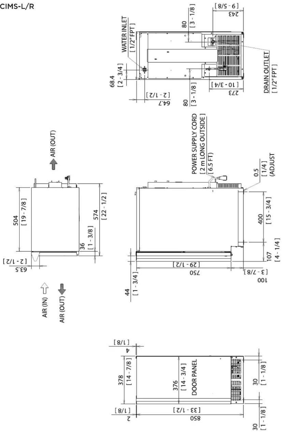
NICHE / PRODUCT DIMENSIONS/CONNECTIONS
2. H80CIMW
Units: mm [in.]
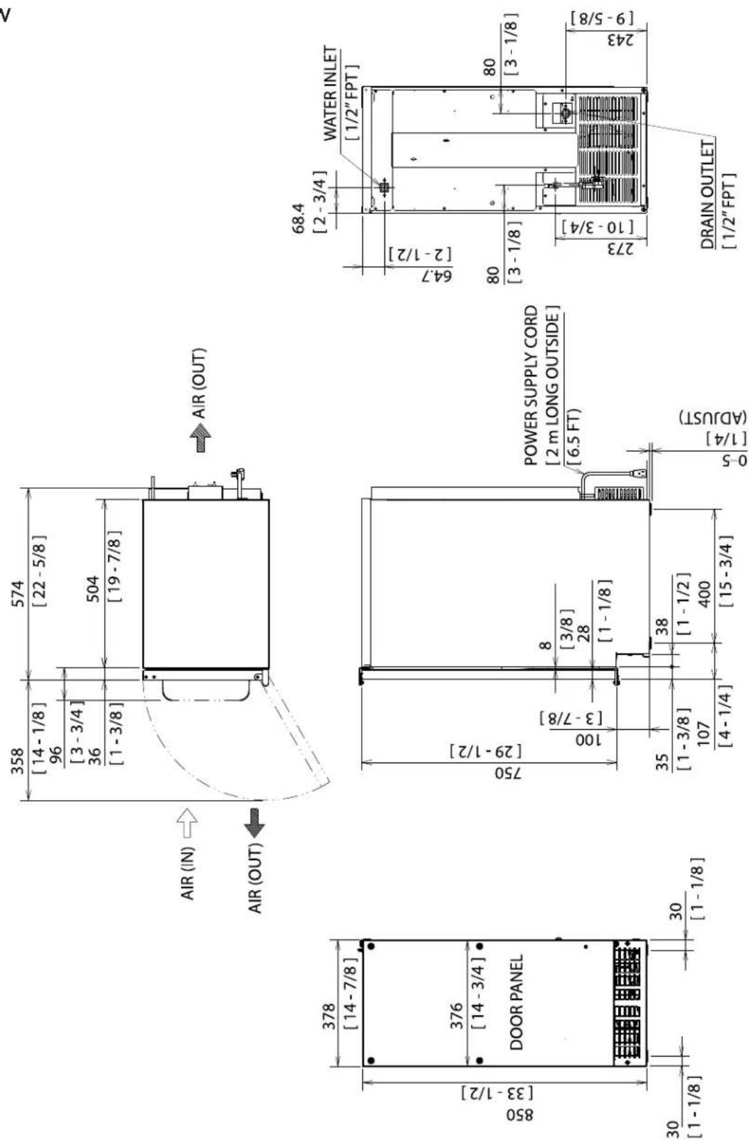
NICHE / PRODUCT DIMENSIONS/CONNECTIONS
- H80CIMS-ADL/R
Units: mm [in.]
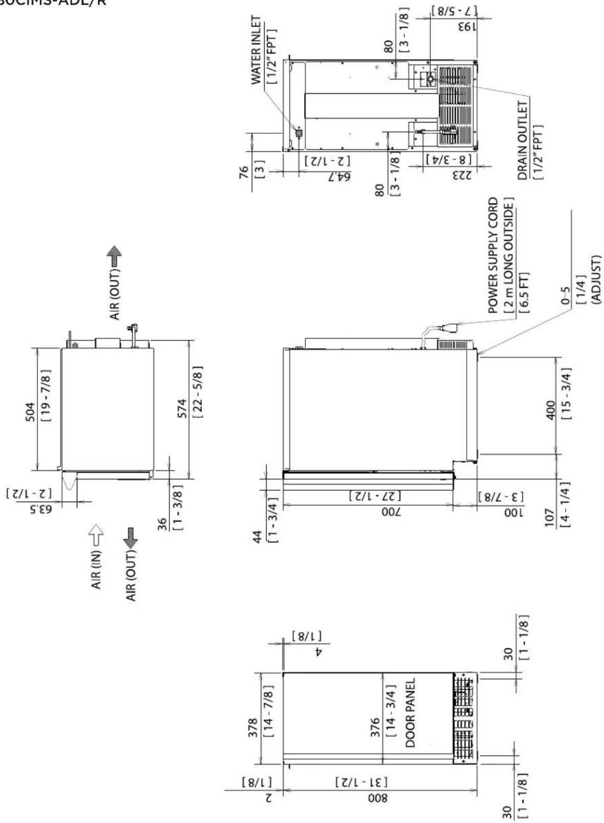
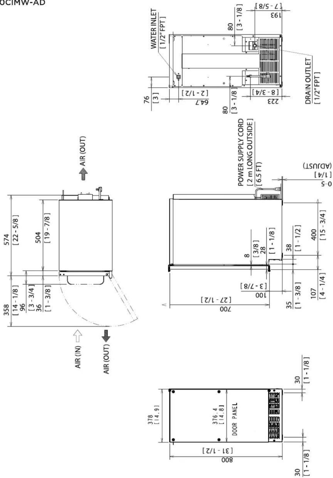
NICHE / PRODUCT DIMENSIONS/CONNECTIONS
4. H80CIMW-AD
Units: mm [in.]
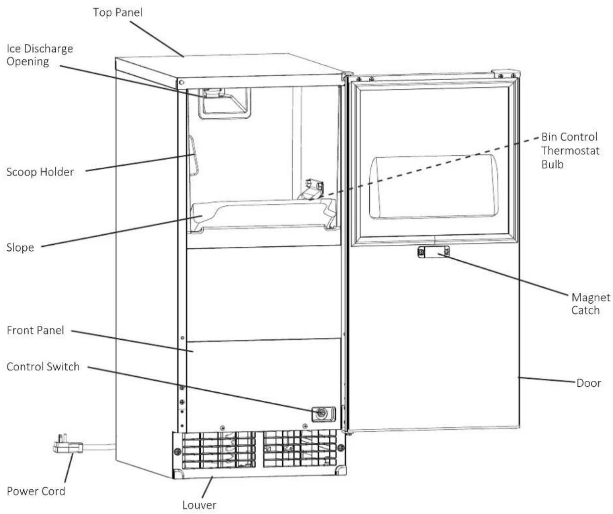
CONSTRUCTION
ELECTRICAL/REFRIGERANT
| Model Number H80CIMS-L | H80CIMS-RH80CIMWH80CIMS-ADLH80CIMS-ADRH80CIMW-AD |
| Electrical Supply 115-120V, | 60 Hz., Phase 1 |
| Power/Cord Type/ Length N | HEMA 5-15P w/6' power cord |
| Design Pressure HI-240PSI | LO-120PSI |
| Refrigerant 134a 3.92 OZ. |
The nameplate provides electrical and refrigerant data. The nameplate is located inside the storage bin. For certification marks, see the nameplate.
We reserve the right to make changes in specifications and design without prior notice.
INSTALLATION INSTRUCTIONS
▲ DANGER must be installed in accordance with applicable national, state, and local codes and regulations.
▲ DANGER ARD: Ensure all components, fasteners, and thumbscrews are securely in place after installation. Make sure that none have fallen into the storage bin.
A. Checks Before Installation
Visually inspect the exterior of the shipping container and immediately report any damage to the carrier. Upon opening the container, any concealed damage should also be immediately reported to the carrier.
Remove the shipping carton, tape, and packing material. If any are left in the appliance, it will not work properly.
Remove the package containing the accessories.
Remove the protective plastic film from the panels. If the appliance is exposed to the sun or to heat, remove the film after the appliance cools.
See the nameplate inside the storage bin, and check that your voltage supplied corresponds with the voltage specified on the nameplate.
The appliance requires no side or top clearance. But allow enough space at rear for water supply and drain connections and at least 15" (38 cm) clearance at front.
The appliance must be at floor level on a finished floor even if under a cabinet. In areas where water damage is a concern, install in a contained area with a floor drain.
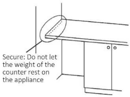
WARNING the weight of the counter rest on the appliance.
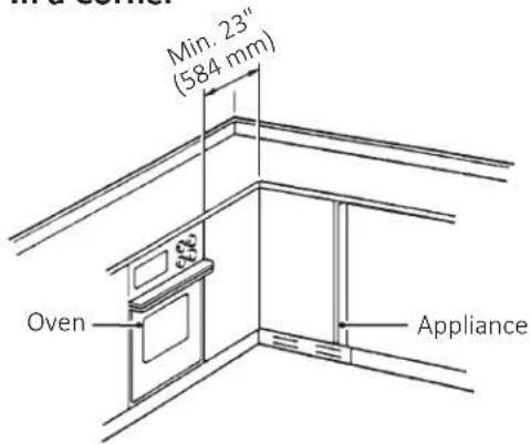
WARNING: the appliance in a corner where the door will interfere with other equipment or where the appliance cannot be pulled out for service.
B. Location
- General
The appliance is approved for indoor or outdoor use.
WARNING rating ambient temperature must be within 45°F to 100°F (7°C to 38°C); Normal operating water temperature must be within 45°F to 90°F (7°C to 32°C). Operation of the appliance, for extended periods, outside of these normal temperature ranges may affect appliance performance.
WARNING The appliance will not work at sub-freezing temperatures. To prevent damage to the water supply line, drain the appliance if the air temperature is going to go below 32^ F ( 0^ C).
The appliance should not be located next to ovens, grills, or other high heat producing equipment.
The location must provide a firm and level foundation for the appliance.
INSTALLATION INSTRUCTIONS
| Installation Space | |||
| Model Height | Width Depth | ||
| H80CIMS H80CIMW | 34" (864 mm) minimum | 15" (381 mm) minimum | 24" (610 mm) mini-mum |
| H80CIMS-AD H80CIMW-AD | 32" (814 mm) minimum | ||
Between Two Cabinets Between a Cabinet and
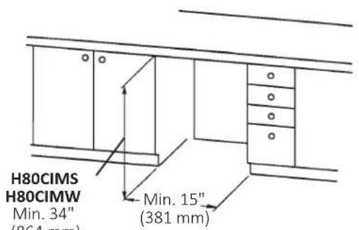
H80CIMS-AD
H80CIMW-AD
Min. 32" (814 mm)
the End of a Counter
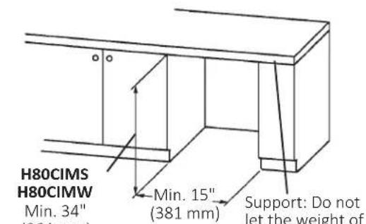
(864 mm)
H80CIMS-AD
H80CIMW-AD
Min. 32" (814 mm)
Between a Cabinet and a Wall or Tall Cabinet
In a Corner
INSTALLATION INSTRUCTIONS
OVERLAY PANEL FABRICATION AND ATTACHMENT
The overlay panel must be crafted by a professional cabinet maker to ensure quality results.
OVERLAY PANEL SPECIFICATION
Use the specification that applies to your appliance (H80CIMW or H80CIMW-AD) and the directions that follow to prepare your overlay panel.
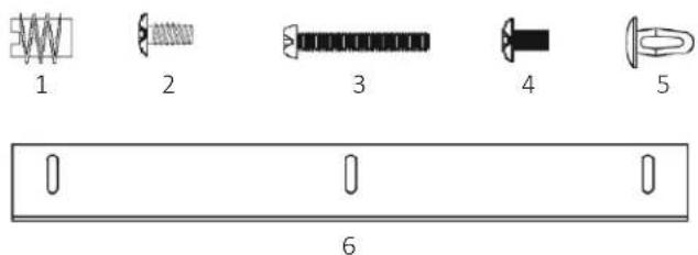
PARTS
Ensure that all parts required for the overlay panel assembly are contained in the accessories bag.
| Overlay Panel Parts | |||
| No. | Description Part Number Qty. | ||
| 1 | Threaded Wood Insert 4A4004-01 6 | ||
| 2 | T2 Screw 4x8 SS 7P32-0408 3 | ||
| 3 | Pan Head Screw M4x25 SS 7C12-0425 4 | ||
| 4 | Truss Head Screw M4x8 SS 7C32-0408 2 | ||
| 5 | Canoe Clip 4A5835-01 2 | ||
| 6 | Sheet Metal Bracket 4A3998-01 1 | ||
H80CIMW
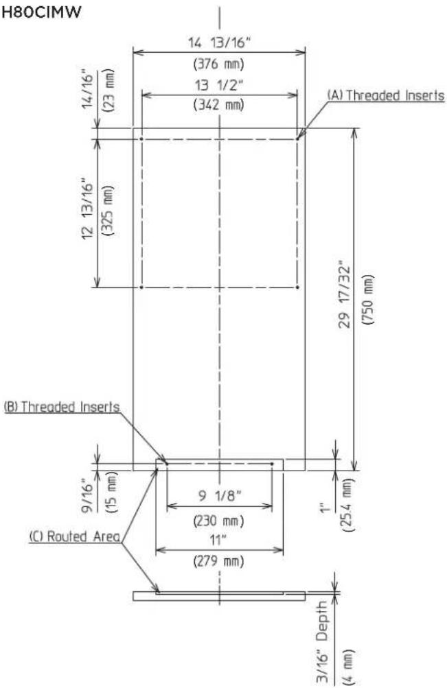
| H80CIMW Overlay Panel Specification | |
| Panel Height 29 17/32" (750 mm) | |
| Panel Width 14 13/16" (376 mm) | |
| Panel Thickness 5/8" (16 mm) min; | 3/4" (19 mm) max |
| Panel and Door Weight (total) 20 lb. (9 kg) max | |
INSTALLATION INSTRUCTIONS
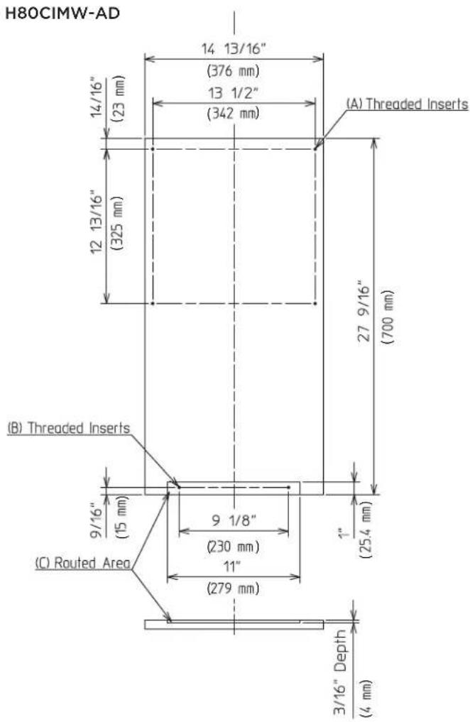
| H80CIMW-AD Overlay Panel Specification | |
| Panel Height 27 9/16" (700 mm) | |
| Panel Width 14 13/16" (376 mm) | |
| Panel Thickness 5/8" (16 mm) min; | 3/4" (19 mm) max |
| Panel and Door Weight (total) 20 lb. (9 kg) max | |
FABRICATION OF OVERLAY PANEL
Fabricate the overlay panel as outlined in the specification on the previous page and the instructions below.
1) Rout a channel at the bottom of the overlay panel to the proper dimensions. See “(C) Routed Area” in the specification diagram and Fig. 1.
2) Drill six 1/4" diameter (hardwood may require slightly larger diameter) holes 3/8" (10 mm) deep in the locations designated.
WARNING Use care when drilling holes for mounting
hardware. All drilled holes must be straight and drilled to the correct diameter and depth.
See “(A) Threaded Inserts” and “(B) Threaded Inserts” in the specification diagram and Fig. 2.
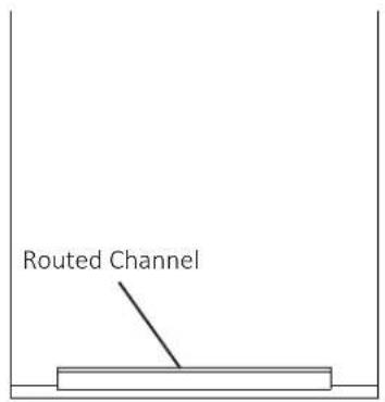
Fig. 1
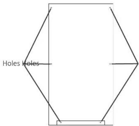
Fig. 2
3) Screw the 6 threaded wood inserts into the 1/4" holes drilled in the previous step. Make sure that the inserts are threaded straight and that the tops of the inserts are flush to the overlay panel surface. Otherwise, the overlay panel cannot be properly fastened to the door.
4) Mount the door handle hardware. Perlick recommends that the door handle hardware be mounted on the edge opposite of the door hinge side (optional hinge reversal is covered in step 6. Countersunk screw heads are required to ensure that the hardware fasteners do not interfere with the overlay panel fitting flush with the door.
INSTALLATION INSTRUCTIONS
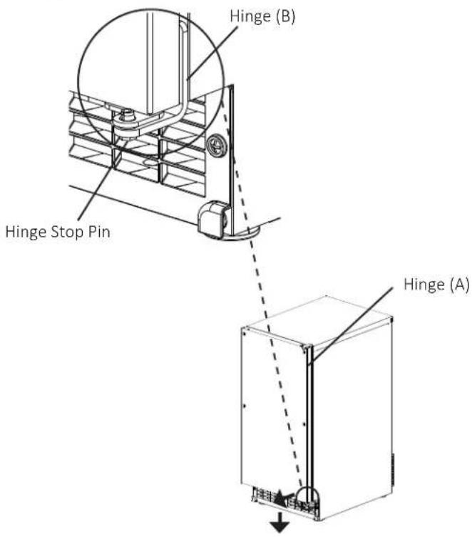
5) While maintaining a hold on the door, remove the hinge stop pin from hinge (B). Pull out the bottom of the door slightly and gently remove the door from hinge (A) (See Fig. 3). If you are leaving the door right hinged, skip to step 7. If you would like to reverse the door hinges, proceed to step 6.
Fig. 3
6) If you would like to reverse the door hinges, do the following:
a) Contact your local distributor to purchase Perlick 70084. The kit contains "hinge (A)-left."
b) Remove the 2 bolts securing the top panel, then lift it off (See Fig. 4).
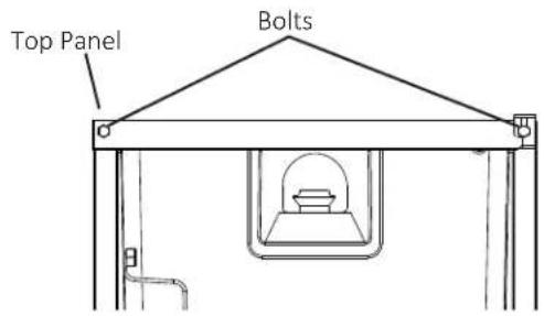
Fig. 4
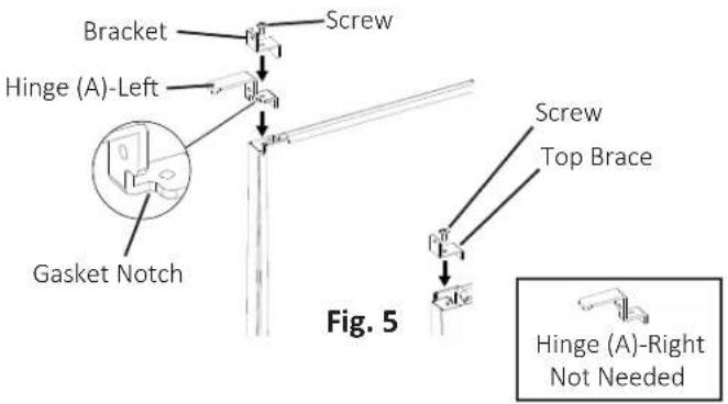
c) Remove hinge (A)-right and the bracket from the right side of the appliance. Set aside hinge (A)-right; it is not needed. Remove the top brace from the left side. Fasten hinge (A)-left and the bracket to the left side and the top brace to the right side (See Fig. 5).
Note: When on the proper side, the gasket notch for hinge (A) is to the inside.
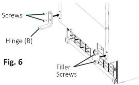
d) Remove hinge (B) from the right side of the appliance and the 2 filler screws from the left side. Attach the 2 filler screws to the right side and attach hinge (B) to the left side (See Fig. 6).
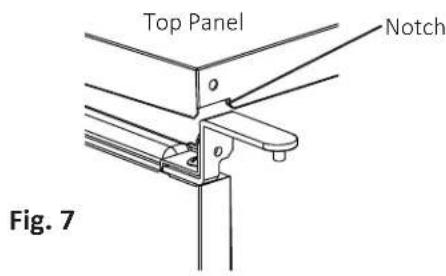
e) Rotate the top panel 180° from its previous position. This brings the notch that was previously in the right rear to the left front (See Fig. 7). Hook the rear part of the panel on the body, then secure the front with the 2 bolts removed in step 6a.
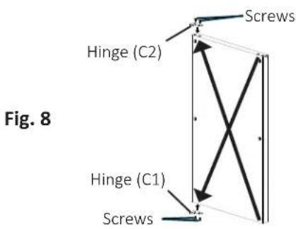
f) Remove hinge (C1) from the top right part of the door, flip it and reattach to the bottom left. Remove hinge (C2) from the bottom right part of the door, flip it and reattach to the top left (See Fig. 8). Proceed to step 7.
INSTALLATION INSTRUCTIONS
7) Remove the bushings from hinge (C1) and hinge (C2) (the hinges attached to the door) (See Fig. 9).
8) Remove the gasket from the door (See Fig. 10).
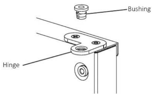
Fig. 9
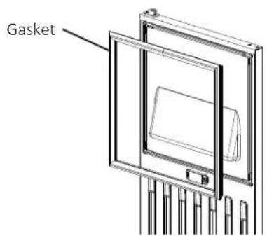
Fig. 10
9) Temporarily fasten the overlay panel to the door using 2 of the M4×25 pan head screws provided.
WARNING Ensure that the back surface of overlay panel is flat before attaching (See Fig. 11).
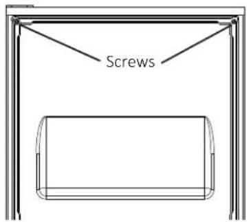
Fig. 11
10) Mark the centerpoint of the hinge (C1) and hinge (C2) holes that extend over the overlay panel (See Fig. 12).
11) Remove the overlay panel from the door.
12) Drill 3/8" diameter holes 1/4" (7 mm) deep where you marked on the overlay panel to accommodate the hinge (C1) and hinge (C2) bushings.
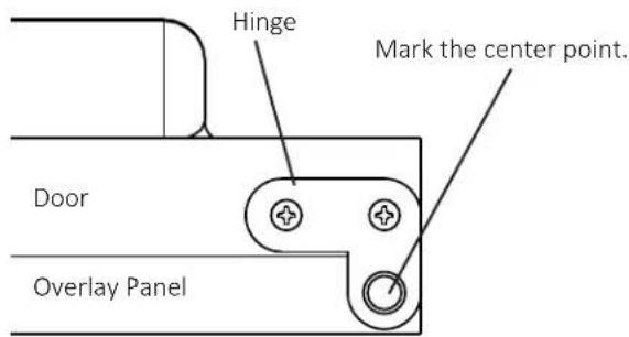
Fig. 12
INSTALLATION INSTRUCTIONS
ATTACHMENT OF OVERLAY PANEL TO DOOR
1) Fasten the sheet metal bracket to the overlay panel using the two M4×8 truss head screws provided. Snug the screws, but do not tighten (See Fig. 13).
2) Temporarily fasten the overlay panel to the door using 2 of the M4×25 pan head screws provided (See Fig. 14).
3) Adjust the sheet metal bracket so that it is flush with the bottom of the door (See Fig. 15).
4) Remove the overlay panel from the door and tighten the two M4x8 truss head screws securing the sheet metal bracket to the overlay panel (See Fig. 16).
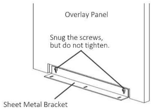
Fig. 13
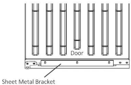
Fig. 15
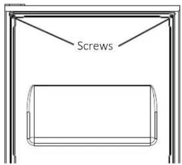
Fig. 14
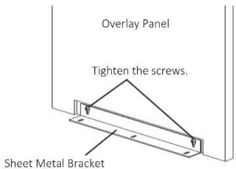
Fig. 16
INSTALLATION INSTRUCTIONS
5) Fasten the overlay panel to the door using the four M4×25 pan head screws provided. Snug the screws, but do not tighten (See Fig. 17).
6) Fasten the sheet metal bracket to the bottom of the door with the three T2 screws provided. Tighten the screws to the door (See Fig. 18).
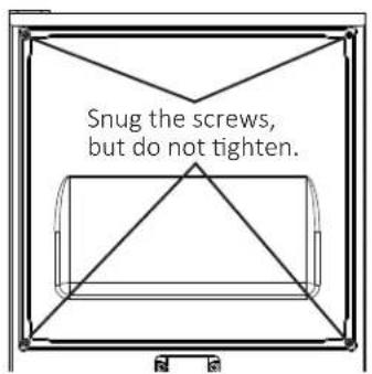
Fig. 17
8) Replace the door gasket in its proper orientation. Reinsert the bushings into hinge (C1) and hinge (C2) (the hinges attached to the door) (See Fig. 20).
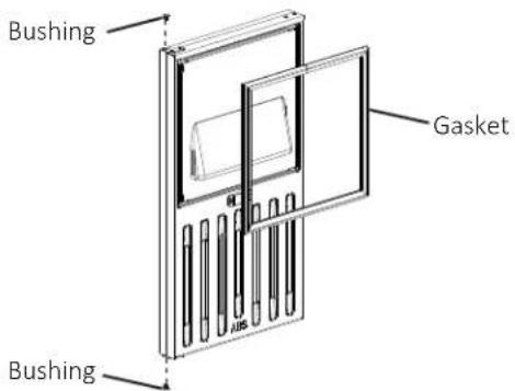
Fig. 20
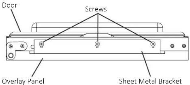
Fig. 18
9) Attach the door to hinge (A), then continue to maintain a hold on the door. Screw the hinge stop pin into hinge (B) until it is tight (See Fig. 21).
10) Insert the 2 canoe clips included in the accessory bag into the holes on top of the door (See Fig. 22).
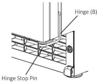
Fig. 21
7) Tighten the four M4×25 pan head screws installed in step 5 (See Fig. 19).
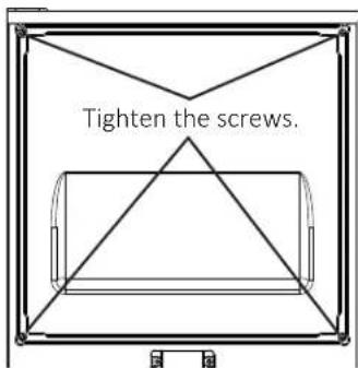
Fig. 19
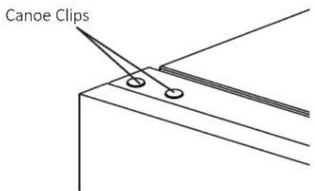
Fig. 22
SETUP
SETUP
1) Position the appliance in the selected permanent location.
2) Level the appliance from side-to-side and front-to-rear by adjusting the feet.
ELECTRICAL CONNECTION
A. DANGER ection must meet national,
state, and local electrical code requirements. Failure to meet these code requirements could result in death, electric shock, serious injury, fire, or damage.
DANGER requires an independent
power supply of proper capacity. See the nameplate for electrical specifications. Failure to use an independent power supply of proper capacity can result in a tripped breaker, blown fuse, damage to existing wiring, or component failure. This could lead to heat generation or fire.
DANGER MUST BE GROUNDED:
The appliance is equipped with a NEMA 5-15 three-prong grounding plug to reduce the risk of potential shock hazards. It must be plugged into a properly grounded, independent 3-prong wall outlet. If the outlet is a 2-prong outlet, it is your personal responsibility to have a qualified electrician replace it with a properly grounded, independent 3-prong wall outlet. Do not remove the ground prong from the power cord and do not use an adapter plug. Failure to properly ground the appliance could result in death or serious injury.
DANGER extension cord.
▲ DANGER risk of electric shock, do not
touch the control switch or plug with damp hands. Make sure the control switch is in the "OFF" position before plugging in or unplugging the appliance.
A. DANGER appliance with a damaged
power cord. The power cord should not be altered, jerked, bundled, weighed down, pinched, or tangled. Such actions could result in electric shock or fire. To unplug the appliance, be sure to pull the plug, not the cord, and do not jerk the cord.
DANGER und wire in the factory-
installed power cord is connected to the appliance. If it becomes necessary to remove or replace the power cord, be sure to connect the power cord's ground wire to this screw upon reattachment.
Usually an electrical permit and services of a licensed electrician are required.
The maximum allowable voltage variation is ±10 percent of the nameplate rating.
For optional drain pump (63802A) installation, refer to the instructions included with the pump.
WATER SUPPLY AND DRAIN CONNECTIONS
WATER SUPPLY AND DRAIN CONNECTIONS
▲ DANGER and drain connections must be installed in accordance with applicable national, state, and local regulations.
WARNING Normal operating water temperature must be within 45°F to 90°F (7°C to 32°C). Operation of the appliance, for extended periods, outside of this normal temperature range may affect appliance performance.
WARNING only pressure must be a minimum of 7 PSIG and a maximum of 113 PSIG. If the pressure exceeds 113 PSIG, the use of a pressure reducing valve is required.
WARNING External filters, strainers, or softeners may be required depending on water quality. Contact your local Perlick Certified Service Representative or local Perlick distributor for recommendations.
WARNING potable water supply only. Do not connect to a hot-water supply.
WARNING In areas where water damage is a concern, install in a contained area with a floor drain.
WARNING installation to the appliance is not warranted by Perlick.
WARNING: hammer issues must be resolved by a qualified plumber before installing the appliance. Water hammer can cause appliance damage that may lead to water leakage or flooding.
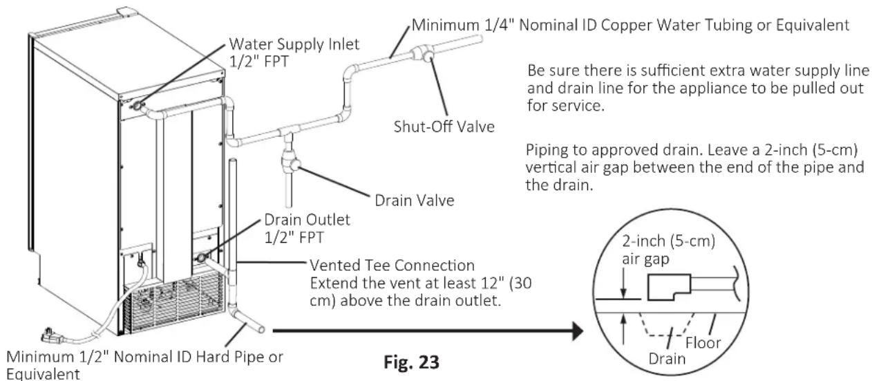
WARNING of 1/2" nominal ID hard pipe or equivalent is required for the drain line. Installing a smaller diameter drain line will reduce water flow and may lead to water leakage or flooding.
WARNING If using the optional drain pump (63802A), test its operation every time the appliance is cleaned and sanitized. If the optional drain pump is not operating properly, water could back up and overflow, leading to costly water damage.
| Water Supply Inlet | Minimum Water Supply Line Size | Drain Outlet | Minimum Drain Line Size |
| 1/2" Female Pipe Thread (FPT) | 1/4" Nominal ID CopperWater Tubing or Equivalent | 1/2" Female Pipe Thread (FPT) | 1/2" Nominal IDHard Pipe or Equivalent |
A plumbing permit and services of a licensed plumber may be required in some areas.
A water supply line shut-off valve and drain valve must be installed.
Be sure there is sufficient extra water supply line and drain line for the appliance to be pulled out for service.
Drain line should not be piped directly to the sewer system
An air gap of a minimum of 2 vertical inches (5 cm) must be between the end of the drain pipe from the appliance and the floor drain.
For gravity drain installation, drain must have 1/4" fall per foot (2 cm per 1 m) on horizontal runs to get good flow. A vented tee connection is also required for proper flow. Extend the vent at least 12" (30 cm) above the drain outlet. For optional drain pump installation, refer to the instructions included with the pump.
FINAL CHECKLIST
FINAL CHECKLIST
▲ DANGER ZARD: Ensure all components, fasteners, and thumbscrews are securely in place after installation. Make sure that none have fallen into the storage bin.
- Is the appliance level?
- Is the appliance in a site where the ambient temperature is within 45^ F to 100^ F ( 7^ C to 38^ C) and the water temperature within 45^ F to 90^ F ( 7^ C to 32^ C) all year around?
- Have the shipping carton, tape, and packing material been removed from the appliance? Has the protective plastic film been removed from the panels?
- Have all electrical and water connections been made? Do electrical and water connections meet all national, state, and local code and regulation requirements?
-
Has the power supply voltage been checked or tested against the nameplate rating? Is the power supply a properly grounded, independent 3-prong wall outlet?
-
Are the water supply and drain lines sized as specified? Are the water supply line shut-off valve and drain valve installed? Has the water supply pressure been checked to ensure a minimum of 7 PSIG and a maximum of 113 PSIG?
- Are all components, fasteners, and thumbscrews securely in place?
- Has the end user been given this instruction manual, and instructed on how to operate the appliance and the importance of the recommended periodic maintenance?
- Has the end user been given the name and telephone number of an authorized service agent?
- Has the warranty tag been filled out and forwarded to the factory for warranty registration?
OPERATING INSTRUCTIONS
IMPORTANT NOTES ABOUT USAGE
A DANGER and service technicians should install and service the appliance.
▲ DANGER call, operate, and maintain the equipment in accordance with this manual will adversely affect safety, performance, component life, and warranty coverage.
▲ DANGER risk of electric shock, do not touch the control switch or plug with damp hands. Make sure the control switch is in the "OFF" position before plugging in or unplugging the appliance.
▲ DANGER must be maintained in accordance with the instruction manual and labels provided with the appliance. Consult with your local Perlick Certified Service Representative about maintenance service.
▲ DANGER must be cleaned and sanitized at least twice a year. More frequent cleaning and sanitizing may be required in some water conditions.
A DANGER ends before removing ice. Use the plastic scoop provided.
▲ DANGER fingers or any other objects into the ice discharge opening.
⚠️ DANGER is not intended for use by persons (including children) with reduced physical, sensory, or mental capabilities, or lack of experience and knowledge, unless they have been given supervision or instruction concerning use of the appliance by a person responsible for their safety.
⚠️ DANGER 1n should be properly supervised around the appliance.
▲ DANGER stand, or hang on the appliance or appliance door or allow children or animals to do so. Serious injury could occur or the appliance could be damaged.
▲ DANGER to pinch fingers when opening and closing the door. Be careful when opening and closing the door when children are in the area.
▲ DANGER mbustible spray or place volatile or flammable substances near the appliance. They might catch fire.
⚠️ DANGER around the appliance clean. Dirt, dust, or insects in the appliance could cause harm to individuals or damage to the appliance.
WARNING Protect the floor when moving the appliance to prevent damage to the floor.
WARNING If using the optional drain pump (63802A), test its operation every time the appliance is cleaned and sanitized. If the optional drain pump is not operating properly, water could back up and overflow, leading to costly water damage.
WARNING To help ensure the storage bin drain remains clear, follow the instructions in Storage Bin Drain once every 3 months or as often as necessary for conditions. If the storage bin drain becomes clogged, water could build up in the bin and overflow, leading to costly water damage.
WARNING If water collects in the bin and will not drain, turn off the appliance and close the water supply line shut-off valve. Call for service.
WARNING If water seeps from the base of the appliance, turn off the appliance and close the water supply line shut-off valve. Call for service. Failure to do so could lead to costly water damage.
WARNING Do not leave the appliance on during extended periods of non-use, extended absences, or in sub-freezing temperatures. To properly prepare the appliance for these occasions, follow the instructions in Preparing the Appliance for Periods of Non-Use.
WARNING Keep ventilation openings in the appliance enclosure or in the built-in structure clear of obstruction.
WARNING Do not place objects on top of the appliance.
WARNING The storage bin is for ice use only. Do not store anything else in the storage bin.
If ice is not used on a regular basis, it may bond together in the storage bin. In this case, discard the bonded ice and allow the appliance to make fresh ice.
STARTUP
STARTUP
▲ DANGER factory-adjusted. Improper adjustments may adversely affect safety, performance, component life, and warranty coverage.
WARNINGance is turned off, wait for at least 3 minutes before restarting the appliance to prevent damage to the compressor.
WARNING, confirm that all internal and external connections are free of leaks.
- Open the water supply line shut-off valve.
- Make sure the control switch is in the "OFF" position. Plug the appliance into the electrical outlet.
⚠ DANGER To reduce the risk of electric shock, do not touch the control switch or plug with damp hands. If you have to slide the appliance back for a built-in installation, make sure you do not damage or pinch the water supply line, drain line, or power cord.
-
If required by sanitation code in your area, seal the perimeter where the appliance touches the floor with approved caulk compound in a smooth and easily cleanable manner.
-
Move the control switch to the "ICE" position to start the automatic icemaking process.
-
Once the appliance starts to produce ice, allow it to run for another 30 minutes.
-
Move the control switch to the "OFF" position.
-
Remove the ice produced, then clean the storage bin liner, door liner, and door gasket using a neutral cleaner. Rinse thoroughly after cleaning.
-
Move the control switch to the "ICE" position to start the automatic icemaking process.
-
To confirm bin control operation, hold ice in contact with the bin control thermostat bulb. If the icemaker does not stop within 10 seconds, the bin control thermostat must be adjusted. Installations at higher altitude locations are more likely to require adjustment.
MAINTENANCE
MAINTENANCE
The appliance must be maintained in accordance with the instruction manual and labels provided with the appliance. Consult with your local Perlick Certified Service Representative about maintenance service. To obtain the name and phone number of your local Perlick Certified Service Representative, visit www.perlick.com.
▲ DANGER and service technicians should service the appliance.
▲ DANGER fall, operate, and maintain the equipment in accordance with this manual will adversely affect safety, performance, component life, and warranty coverage.
▲ DANGER risk of electric shock, do not touch the control switch or plug with damp hands. Make sure the control switch is in the "OFF" position before plugging in or unplugging the appliance.
⚠️ DANGER control switch to the "OFF"
position and unplug the appliance from the electrical outlet
before servicing.
▲ DANGER ZARD: Ensure all components, fasteners, and thumbscrews are securely in place after any maintenance is done to the appliance. Make sure that none have fallen into the storage bin.
A DANGER fingers or any other objects into the ice discharge opening.
▲ DANGER make sure that there are no wires pinched between the panels and appliance. Make sure you do not damage or pinch the water supply line, drain line, or power cord.
MAINTENANCE
MAINTENANCE SCHEDULE
| Frequency Area | Task | |
| Weekly Scoop Clean the scoop using a neutral cleaner. Rinse thoroughly after cleaning. | ||
| Monthly | Drain the Appliance M | move the control switch to the "DRAIN" position. Allow the water system to drain for 1 minute. Clear ice away from the thermostatic bin control bulb. Move the control switch to the "ICE" position. After the gear motor starts, move the control switch to the "DRAIN" position. Allow the water system to drain for 1 minute. Move the control switch to the "ICE" position to start the automatic icemaking process. |
| Appliance Exterior Wipe down with clean, soft cloth. Use a damp cloth containing a neutral cleaner to wipe off oil or dirt build up. Clean any chlorine staining (rust colored spots) using a non-abrasive cleanser. | ||
| Every 3 Months Storage Bin Drain Maintain as outlined in Storage Bin Drain (pg 30) | ||
| Every 6 Months Icemaker and Storage Bin | Clean and sanitize per the cleaning and sanitizing instructions provided in this manual. | |
Wipe down with clean cloth and warm water.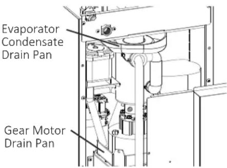 | ||
| Optional Drain Pump (63802A) Test as outlined in Optional Drain Pump 63802A instructions | ||
| External Water Filters Check for proper pressure and change if necessary. | ||
| Yearly Water Supply Inlet Close the water supply line shut-off valve and drain the water system. Clean the water supply inlet screen. | ||
| Condenser Inspect. Clean if necessary. | ||
| Water Hoses Inspect the water hoses and clean/replace if necessary. | ||
| Upper Bearing (extruding head) Check for wear using .02" round stock or pin gauge. Replace both upper bearing and lower bearing if wear exceeds factory recommendations. | ||
| After 3 Years, then Yearly | Upper Bearing (extruding head); Lower Bearing and O-Ring (lower housing); Mechanical Seal; Evaporator Cylinder; Auger | Inspect. Replace both upper bearing and lower bearing if wear exceeds factory recommendations. Replace the mechanical seal if the seal's contact surfaces are worn, cracked, or scratched. |
MAINTENANCE
CLEANING AND SANITIZING INSTRUCTIONS
The appliance must be cleaned and sanitized at least twice a year. More frequent cleaning and sanitizing may be required in some conditions.
▲ DANGER Injury to individuals and damage to the appliance, do not use ammonia type cleaners.
A DANGER how any instructions provided with the cleaning and sanitizing solutions.
▲ DANGER liquid-proof gloves and goggles to prevent the cleaning and sanitizing solutions from coming into contact with skin or eyes.
▲ DANGER be made from the cleaning and sanitizing solutions. After cleaning and sanitizing, be careful not to leave any solution in the appliance.
▲ DANGER fingers or any other objects into the ice discharge opening (extruding head).
1. Cleaning Solution
Dilute 1.6 fl. oz. (47 ml or 3.2 tbs) of Nu-Calgon "Liquid Ice Machine Cleaner" with 1 qt (1 l) of warm water. This is a minimum amount. Make more solution if necessary.
CAUTION and maximum effectiveness, use the solution immediately after dilution.
2. Cleaning Procedure
1) Move the control switch to the "OFF" position.
2) Remove all ice from the storage bin.
3) Move the control switch to the "DRAIN" position.
4) Allow the water system to drain for 1 minute.
5) Move the control switch to the "OFF" position.
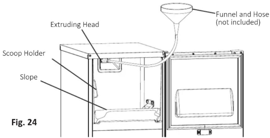
6) Using a clean funnel and hose (not included), pour 1 qt (1 l) of cleaning solution over the extruding head (See Fig. 24.) Allow the appliance to sit for 10 minutes before operation.
7) Make sure at least 10 minutes have elapsed since you poured the cleaning solution over the extruding head, then move the control switch to the "ICE" position.
8) Allow the appliance to make ice for 20 minutes, then
move the control switch to the "DRAIN" position.
9) Allow the water system to drain for 1 minute.
10) Move the control switch to the "ICE" position.
11) After the gear motor starts, move the control switch to the "DRAIN" position.
12) Allow the water system to drain for 1 minute.
13) Move the control switch to the "OFF" position. In severe water conditions, repeat the cleaning procedure.
MAINTENANCE
CLEANING AND SANITIZING INSTRUCTIONS (cont.)
3. Sanitizing Solution
Dilute 1.25 fl. oz. (37 ml or 2.5 tbs) of a 5.25% sodium hypochlorite solution (chlorine bleach) with 2.5 gallons (9.5 l) of warm water. This is a minimum amount. Make more solution if necessary. Using a chlorine test strip or other method, confirm that you have a concentration of about 200 ppm.
CAUTION and maximum effectiveness, use the solution immediately after dilution.
4. Sanitizing Procedure - Initial
1) Using a clean funnel and hose, pour 1 qt (1 l) of sanitizing solution over the extruding head. Allow the appliance to sit for 10 minutes before operation.
2) Remove the slope from the storage bin by carefully bending it in the center and releasing it from the 2 slope shafts.
3) Remove the scoop. Remove the 2 thumbscrews securing the scoop holder, then remove it.
4) Pour some of the sanitizing solution into a separate, clean container. Using this sanitizing solution and a clean cloth, wipe down the slope, scoop, scoop holder, inside of the spout, and bin liner.
5) Rinse the parts and areas sanitized in step 4 thoroughly with clean water.
6) Replace all removed parts in their original and correct positions.
▲ DANGER AZARD: Ensure all components, fasteners, and thumbscrews are securely in place. Make sure that none have fallen into the storage bin.
7) Make sure at least 10 minutes have elapsed since you poured the sanitizing solution over the extruding head, then move the control switch to the "ICE" position.
8) Allow the appliance to make ice for 20 minutes, then move the control switch to the "DRAIN" position.
9) Allow the water system to drain for 1 minute.
10) Move the control switch to the "ICE" position.
11) After the gear motor starts, move the control switch to the "DRAIN" position.
12) Allow the water system to drain for 1 minute.
13) Move the control switch to the "OFF" position.
5. Sanitizing Procedure - Final
1) Using a clean funnel and hose, pour 1 qt (1 l) of sanitizing solution over the extruding head. Allow the appliance to sit for 10 minutes before operation.
2) Move the control switch to the "ICE" position.
3) Allow the appliance to make ice for 20 minutes, then move the control switch to the "DRAIN" position.
4) Allow the water system to drain for 1 minute.
5) Move the control switch to the "ICE" position.
6) After the gear motor starts, move the control switch to the "DRAIN" position.
7) Allow the water system to drain for 1 minute.
8) Move the control switch to the "ICE" position and allow the appliance to run. Check for leaks.
9) After 30 minutes, move the control switch to the "OFF" position.
10) Pour warm water into the storage bin to melt all of the ice, then clean the storage bin liner, door liner, and door gasket with a neutral cleaner. Rinse thoroughly after cleaning.
11) Move the control switch to the "ICE" position to start the automatic icemaking process.
MAINTENANCE
STORAGE BIN DRAIN
In some conditions, slime may build up inside the storage bin drain and prevent water from draining properly. To prevent this buildup, perform the following procedure once every 3 months or as often as necessary for conditions.
WARNING gel bin drain becomes clogged, water could build up in the bin and overflow, leading to costly water damage.
1) Move the control switch to the "OFF" position
▲ DANGER: risk of electric shock, do not touch the control switch with damp hands.
2) Remove all ice from the storage bin.
3) Mix a batch of sanitizing solution by diluting 1.25 fl.oz. (37 ml or 2.5 tbs) of a 5.25% sodium hypochlorite solution (chlorine bleach) with 2.5 gallons (9.5 l) of warm water. Using a chlorine test strip or other method, confirm that you have a concentration of about 200 ppm.
CAUTION and maximum effectiveness, use the solution immediately after dilution.
4) Slowly pour the sanitizing solution into the storage bin.
5) After all of the solution has drained, clean the storage bin liner with a neutral cleaner. Rinse thoroughly with clean water.
6) Move the control switch to the "ICE" position to start the automatic icemaking process.
CONDENSER
Check the condenser once a year, and clean if required by following the steps below. More frequent cleaning may be required depending on location.
▲ DANGER Condenser fins are sharp. Use care when cleaning.
1) Move the control switch to the "OFF" position, then unplug the appliance from the electrical outlet
▲ DANGER risk of electric shock, do not touch the control switch or plug with damp hands.
2) Remove the screws securing the front panel, then remove it (See Fig. 25).
3) Remove the screws securing the louver, then remove it.
4) Use a brush attachment on a vacuum cleaner to gently clean the condenser fins. Do not use too much force, otherwise the fins could be damaged.
5) Replace the louver and front panel in their correct positions. Ensure that the screws are securely in place.
6) Plug the appliance back in. Move the control switch to the "ICE" position to start the automatic ice making process.
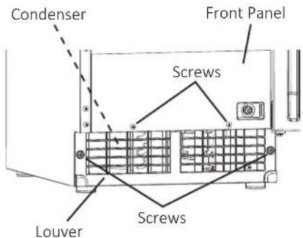
Fig. 25
MAINTENANCE
OPTIONAL DRAIN PUMP
If the optional drain pump (63802A) is installed, test its operation at least twice a year as outlined below. Note that the pump has power even when the control switch is in the "OFF" position.
WARNING that drain pump is not operating properly, it will adversely affect performance, component life, and warranty coverage and may result in costly water damage.
1) Move the control switch to the "OFF" position, then unplug the appliance from the electrical outlet
▲ DANGER risk of electric shock, do not touch the control switch or plug with damp hands.
2) Remove all ice from the storage bin.
3) Plug the appliance back in.
4) Slowly pour 24 to 30 oz. (710 to 890 ml) of water over the storage bin drain hole in the storage bin.
5) If water pumps out properly and the drain pump then de-energizes, proceed to step 6. If water does not pump out properly and/or the drain pump does not de-energize, the appliance must be serviced by a qualified service technician before proceeding.
6) Move the control switch to the "ICE" position.
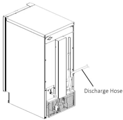
7) Pour another 24 to 30 oz. (710 to 890 ml) of water into the appliance's ice storage bin, then completely restrict the discharge hose while the drain pump is operating (See Fig. 26). Pour more water into the appliance's ice storage bin until the appliance turns off. The drain pump will continue to operate. Check for leaks.
8) Remove the discharge hose restriction and allow the water to be pumped out normally. Power to the appliance will be restored when the water in the drain pump returns to a normal level.
9) If the appliance fails to turn off with the discharge hose restricted or the pump fails to pump out the water, the appliance must be serviced by a qualified service technician.
Fig. 26
PREPARING THE APPLIANCE FOR PERIODS OF NON-USE
PREPARING THE APPLIANCE FOR PERIODS OF NON-USE
During extended periods of non-use, extended absences, or in sub-freezing temperatures, follow the instructions below. When the appliance is not used for two or three days under normal conditions, it is sufficient to move the control switch to the "OFF" position.
▲ DANGER service technicians should service the appliance.
WARNING-nded periods of non-use, extended absences, or in sub-freezing temperatures, follow the instructions below to reduce the risk of costly water damage.
1) Move the control switch to the "OFF" position.
▲ DANGER To reduce the risk of electric shock, do not touch the control switch or plug with damp hands.
2) Close the water supply line shut-off valve, then open the water supply line drain valve. See Fig. 23.
3) Allow the line to drain by gravity.
4) Move the control switch to the "DRAIN" position.
5) Allow the water system to drain for 1 minute.
6) Attach a compressed air or carbon dioxide supply to the water supply line drain valve.
7) Move the control switch to the "ICE" position.
8) Blow the water supply line out using the compressed air or carbon dioxide supply.
9) Close the water supply line drain valve.
10) Move the control switch to the "OFF" position, then unplug the appliance from the electrical outlet.
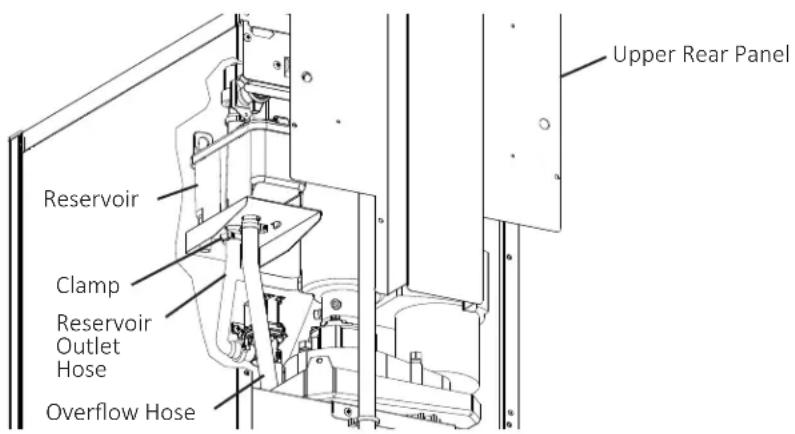
11) Remove the screws securing the upper rear panel, then remove it (See Fig. 27).
12) Remove the clamp securing the reservoir outlet hose to the reservoir. Disconnect the reservoir outlet hose from the reservoir.
13) Attach a compressed air or carbon dioxide supply to the reservoir outlet hose.
14) Plug the appliance back in, then move the control switch to the "DRAIN" position.
15) Blow out the reservoir outlet hose using the compressed air or carbon dioxide supply.
16) Move the control switch to the "OFF" position, then unplug the appliance from the electrical outlet.
17) Reconnect the reservoir outlet hose to the reservoir, then secure with the clamp. Make sure all hoses are connected and secure.
18) Replace the rear panel in its correct position.
19) Clean the storage bin by using a neutral cleaner. Rinse thoroughly after cleaning.
Fig. 27
DISPOSAL
DISPOSAL
The appliance contains refrigerant and must be disposed of in accordance with applicable national, state, and local codes and regulations. Refrigerant must be recovered by properly certified service personnel.
natural_image
Three-panel black-and-white photo collage showing ice cubes and a refrigerator, no visible text or symbolsPerlick
Perlick Residential is a division of Perlick Corporation
© 2018 Perlick Corporation
8300 West Good Hope Road, Milwaukee, WI 53223, USA
perlick.com/residential • (800) 558-5592
FORM NO. Z2547
REV. A-05/01/2018
1A5237-01
- H80CIM/-AD PRODUCT MANUAL
- PERLICK RESIDENTIAL UNDERCOUNTER ICE MAKERS
- CONTENTS
- INTRODUCTION
- WARRANTY REGISTRATION
- SAFETY CONSIDERATIONS
- IMPORTANT SAFETY INFORMATION
- DAMANGERicates that a hazardous situation
- WARNING: a situation where minor
- ⚠️ DANGER is not intended for use by
- ▲ DANGER should be properly
- ▲ DANGER stand, or hang on the
- DANGER to pinch fingers when
- A DANGER Humbustible spray or place
- ▲ DANGER around the appliance clean.
- PRIOR TO INSTALLATION
- NICHE / PRODUCT DIMENSIONS/CONNECTIONS
- H80CIMW
- H80CIMW-AD
- CONSTRUCTION
- ELECTRICAL/REFRIGERANT
- INSTALLATION INSTRUCTIONS
- Checks Before Installation
- Location
- OVERLAY PANEL FABRICATION AND ATTACHMENT
- OVERLAY PANEL SPECIFICATION
- PARTS
- FABRICATION OF OVERLAY PANEL
- WARNING Use care when drilling holes for mounting
- ATTACHMENT OF OVERLAY PANEL TO DOOR
- SETUP
- ELECTRICAL CONNECTION
- DANGER ection must meet national,
- DANGER requires an independent
- DANGER MUST BE GROUNDED:
- DANGER extension cord.
- ▲ DANGER risk of electric shock, do not
- DANGER appliance with a damaged
- DANGER und wire in the factory-
- WATER SUPPLY AND DRAIN CONNECTIONS
- FINAL CHECKLIST
- OPERATING INSTRUCTIONS
- IMPORTANT NOTES ABOUT USAGE
- STARTUP
- MAINTENANCE
- CLEANING AND SANITIZING INSTRUCTIONS
- Cleaning Solution
- Cleaning Procedure
- CLEANING AND SANITIZING INSTRUCTIONS (cont.)
- Sanitizing Solution
- Sanitizing Procedure - Initial
- Sanitizing Procedure - Final
- STORAGE BIN DRAIN
- ▲ DANGER: risk of electric shock, do not touch the control switch with damp hands.
- CONDENSER
- ▲ DANGER Condenser fins are sharp. Use care when cleaning.
- ▲ DANGER risk of electric shock, do not touch the control switch or plug with damp hands.
- OPTIONAL DRAIN PUMP
- PREPARING THE APPLIANCE FOR PERIODS OF NON-USE
- ▲ DANGER service technicians should service the appliance.
- ▲ DANGER To reduce the risk of electric shock, do not touch the control switch or plug with damp hands.
- DISPOSAL
- Perlick
Brand : Perlick
Model : H80CIMS-ADR
Category : Ice Maker