
Microflex Complete Wireless - Desk Phone SHURE - Free user manual and instructions
Find the device manual for free Microflex Complete Wireless SHURE in PDF.


| Product Type | Microflex Complete Wireless Conference System (Wireless Desk Phone) |
| Model | MXCW (MXCWAPT Access Point, MXCW640 Conference Unit, MXCWNCS Charging Station, SB930 Battery) |
| Maximum Conference Units | 125 |
| Frequency Bands | 2.4 GHz ISM, 5 GHz UNII (IEEE 802.11 a/g) |
| RF Output Power (MXCWAPT) | 1 mW (Low), 5 mW (Medium), 13 mW (High), 25 mW (Maximum) |
| Operating Range (Line-of-Sight) | 8 m (Low), 15 m (Medium), 30 m (High), 45 m (Maximum) |
| Audio Latency | 16 ms (Mic to Speaker/Headphone), 9.2 ms (Mic to Analog Out) |
| Audio Channels | 8 Uplink (speaking), 9 Downlink (1 floor mix + 8 interpretation) |
| Encryption | AES-128 (audio and data) |
| Digital Audio Networking | Dante (10 input + 10 output channels) |
| Analog Connections (MXCWAPT) | 1 XLR input (line/aux), 1 XLR output, ground lift switch |
| Conference Unit Display | 4.3 in. color TFT LCD capacitive touchscreen, 480x272 |
| Battery (SB930) | Rechargeable Li-Ion, 35 Wh, typical operating time 11 hours |
| Charging Station (MXCWNCS) | Charges up to 10 batteries, 100% in 4 hours; storage mode available |
| Dimensions (MXCWAPT) | 47.8 x 242.5 x 241.8 mm (1.88 x 9.55 x 9.52 in) |
| Dimensions (MXCW640 with battery) | 70.2 × 148 × 257.5 mm (2.8 × 5.8 × 10.1 in) |
| Dimensions (MXCWNCS) | 72.4 x 438.9 x 193.5 mm (2.9 x 17.3 x 7.6 in) |
| Weight (MXCWAPT) | 1.15 kg |
| Weight (MXCW640 with battery) | 1.21 kg |
| Weight (MXCWNCS) | 2.825 kg |
| Power Supply (MXCWAPT) | Power over Ethernet (PoE), 37-57 V, 12.95 W max |
| Power Supply (MXCWNCS) | 100-240 V AC, 50/60 Hz, 2 A max |
| Battery Care | Store at 40% charge, clean contacts with alcohol, do not expose above 60°C |
| Safety Certifications | FCC Part 15, CE, IC, EAC, ANATEL, etc. |
| Accessories Included | Gooseneck microphones (MXC416/420/425/406), replacement buttons, mounting bracket |
| Repairability | No user-serviceable parts; contact qualified service personnel; factory reset via recessed button |
Frequently Asked Questions - Microflex Complete Wireless SHURE
User questions about Microflex Complete Wireless SHURE
0 question about this device. Answer the ones you know or ask your own.
Ask a new question about this device
Download the instructions for your Desk Phone in PDF format for free! Find your manual Microflex Complete Wireless - SHURE and take your electronic device back in hand. On this page are published all the documents necessary for the use of your device. Microflex Complete Wireless by SHURE.
USER MANUAL Microflex Complete Wireless SHURE
Complete user guide for the MXCW system. Includes installation instructions, specifications, best practices, and troubleshooting.
Version: 10.6 (2022-C)
Table of Contents
MXCW Microflex® Complete Wireless 5
General Description 5
Features 5
Getting Started 6
Set Up the System Access Point (MXCWAPT) 6
Set Up Wireless Conference Units (MXCW640) 7
Perform a Soundcheck 7
Access Point Transceiver (MXCWAPT) 8
Access Point Menu 11
Conference Unit (MXCW640) 13
Gooseneck Microphone (MXC416, MXC420, MXC425, MXC406/MS) 14
Using the Conference Units 15
Lock Conference Unit Power Button 16
Customize Welcome Screen 17
How to Lock the Welcome Screen 17
Conference Unit Buttons 17
Rechargeable Battery (SB930) 18
Battery Life 19
Important Tips for Care and Storage of Shure Rechargeable Batteries 19
Networked Charging Station (MXCWNCS) 19
Powering On the Device 21
Monitoring Battery Charge 21
Icons for Charging Batteries 21
Charge Status LEDs 21
Average Charging Times 22
Charging Batteries with USB 22
Battery Statistics 23
Storing Batteries 24
Access Point Installation 24
Best Practices When Selecting a Location for the Access Point 24
Requirements Checklist 25
External Cover for Painting 25
Mounting Options 25
Networked Charging Station Installation 26
Best Practices for Rack Installation 27
System Set Up 27
Maximum System Size 27
Wireless Device Network 28
Connecting Devices for the First Time 28
Restricting New Device Connections 29
Custom Network SSID Labels 29
Separating Networks for Multiple Systems 30
Web Applications for Monitoring and Control 32
Opening the Device Web Application 32
Web Browser Requirements 34
Using DNS to Open Web Application 34
Web Application Views 34
Using a Passphrase 35
Wireless and RF Management 35
Wireless Operating Distance 36
Reliable Bandwidth Allocation 37
Selecting or Excluding Specific Wireless Channels 37
Interference Detection and Avoidance 38
Tips to Improve Wireless System Performance 38
Setting the Access Point Country and Region (MX-CWAPT-B and MXCWAPT-W only) 38
Setting Up Participants 39
Participant Roles 39
Configuring Conference Units for Remote Callers 40
Speak Priority for Remote Callers 40
Changing the Participant Role 40
Identifying a Device from the Software 41
Customizing the Devices Page 41
Assigning Names and Seat Numbers 43
Retain Seat Information 43
NFC Card Functionality 43
Speak Priority 43
Active Speaker Interruption 44
Microphone Activation Style 44
Setting the Number of Active Speakers 45
Prevent Speak Button Conflicts 46
Audio Setup and Channel Routing 46
MXCW Routing Descriptions 48
MXCW Wireless Audio 48
The Floor Mix 49
Analog Connections 50
Connecting Analog Devices 50
Automatic Gain Control (AGC) 51
Adding Other Sources to the Floor Mix 51
Language Interpretation 55
Set Up Interpretation Channels 55
Conference Unit Interpretation Channels 56
Digital Audio Networking 56
Dante Network Audio 56
Switch Recommendations for Dante Networking 57
QoS (Quality of Service) Settings 57
Dante Network Audio Encryption 58
Networking 58
Networking Best Practices 58
Device IP Settings 58
Configuring IP Settings 58
Manually Assigning Static IP Address 59
Setting Latency 59
Using the Web Application with a Wireless Connection 59
IP Ports and Protocols 60
AES67 61
Voting 61
Voting Configurations 62
Voting Results 63
System Maintenance and Troubleshooting 63
Troubleshooting 63
Resetting Devices 64
Export Log Files 65
Firmware 65
Firmware Updates 65
Update Firmware for Conference Units 65
Firmware Versioning 65
Using a Third-Party Control System 65
Accessories 65
Gooseneck Microphones 66
Optional Accessories and Replacement Parts 66
Access Point Model Variations 66
Networked Charging Station Model Variations 67
Specifications 67
System 68
MXCWAPT 68
MXCW640 72
MXCWNCS 78
SB930 80
Important Product Information 81 Safety Information 82
Information to the user
84
Certifications
84
Trademarks
87
MXCW
Microflex® Complete Wireless
General Description
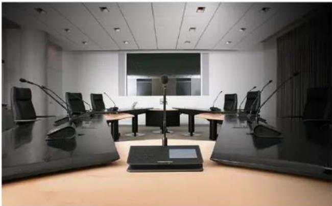
The Shure Microflex ^® Complete Wireless (MXCW) system is a conferencing solution that provides a steady, reliable audio experience for up to 125 conference units. MXCW overcomes cable limitations for off-site meetings, flexible meeting rooms, or historic buildings where drilling holes in furniture is impractical. The system features automatic RF interference detection and avoidance technology, encrypted digital wireless transmission, and digital audio networking using Dante ^® .
The MXCW access point has multiple mounting options for discreet communication between wireless conference units and the digital audio network, and works within the 2.4 GHz and 5 GHz frequency bands. Use the access point web application for system setup, and to monitor and control conference units. Conference units have configurable roles for meeting participants, and can be routed to the floor audio or an interpretation channel. Each wireless conference unit is powered by a smart lithium-ion rechargeable battery whose remaining charge can be checked remotely by a technician. The MXCW networked charging station charges and stores up to 10 Shure rechargeable batteries that can be monitored through its own web application.
natural_image
Interior view of a modern conference room with microphones and a U-shaped table (no visible text or signage)Features
| RF Efficiency | Sound quality is consistent with one speaker or several, and up to 125 units are supported with just one access point transceiver and one RF channel. |
| Automatic Frequency Co-ordination | The system automatically scans the available spectrum and selects clean transmission channels for best performance. Setting up the system is as easy as setting up a wireless router. |
| Interference Avoidance | While in use, the system automatically moves away from unexpected interference. Channel adjustment protects against disruption to the audio. |
| Encryption | Standard AES-128 encryption of audio and data keeps meeting content private. |
| Bi-Directional Wireless | Provides return channels for interpretation audio to conference units and enables real-time remote control of conference unit settings. |
Getting Started
Set Up the System Access Point (MXCWAPT)
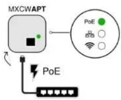
- Connect the access point to a Power over Ethernet (PoE) source to turn on the device.
flowchart
graph TD
    A["MPCWAPT"] --> B["Central Device"]
    B --> C["Sensor 1: Wi-Fi"]
    B --> D["Sensor 2: Sensor 0"]
    B --> E["Sensor 3: Sensor 4"]
    B --> F["Sensor 4: Sensor 5"]
    B --> G["Sensor 5: Sensor 6"]
    B --> H["Sensor 6: Sensor 7"]
    B --> I["Sensor 7: Sensor 8"]
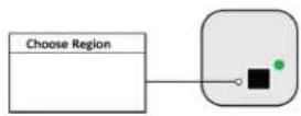
- If prompted, select the operating region on the menu for RF coordination (some model variations).
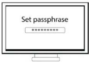
- Open the web application in a browser and set an Admin passphrase.
- Wait while the access point scans the area for the best available channel.
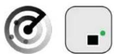
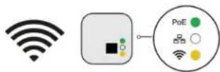
- Once the channel is selected, the default wireless network (00) is ready for the MXCW microphones.
Set Up Wireless Conference Units (MXCW640)
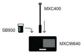
- Insert a fully charged Shure SB930 rechargeable battery and connect the MXC400 series microphone.
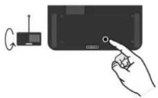
- Press and hold the power button on the bottom of the device until the screen powers on.
natural_image
Illustration of a hand pressing a button on a device with a small antenna nearby (no text or symbols)- Wait while the microphone device searches for the default access point network (00).
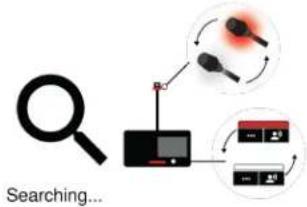
flowchart
graph TD
    A["Searching..."] --> B["Monitor"]
    B --> C["Data Processing"]
    C --> D["Feedback Loop"]
    D --> E["Output"]
    style A fill:#f9f,stroke:#333
    style B fill:#ccf,stroke:#333
    style C fill:#cfc,stroke:#333
    style D fill:#fcc,stroke:#333
    style E fill:#ffc,stroke:#333
- The devices are ready when the LEDs briefly flash green and the touchscreen displays the home-screen.
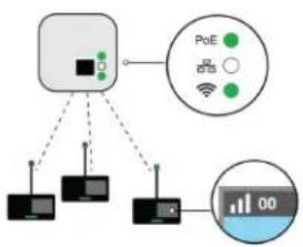
flowchart
graph TD
    A["Central Device"] --> B["Pod 1"]
    A --> C["Pod 2"]
    A --> D["Pod 3"]
    A --> E["Pod 4"]
    B --> F["Wi-Fi Signal"]
    C --> G["Digital Display"]
    D --> H["Digital Display"]
    E --> I["Digital Display"]
Perform a Soundcheck
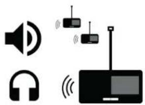
- Press the 🔊 speak button on one of the devices to activate the microphone.
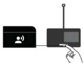
natural_image
Illustration of a hand interacting with a device via a wireless signal and antenna (no text or symbols)- Speak into the microphone to check the audio.
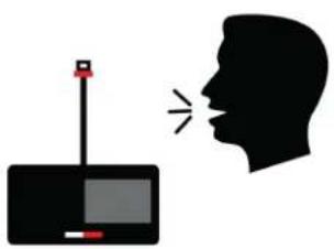
natural_image
Silhouette of a human face with a sound wave emitting from the right side of a device (no text or symbols)- Listen to the sound check on the loudspeakers or headphone output.
natural_image
Pure electrical circuit lines without any symbolsAccess Point Transceiver (MXCWAPT)
The access point transceiver is the hub of the audio signal flow and manages the RF stability of each microphone in the group. The access point performs the following functions:
- Receives and decrypts wireless audio signals from microphones in the group
- Delivers and receives digital and analog audio signals via Dante and XLR
- Hosts an embedded web server that provides access to the control software used to manage the system
- Sends and receives control information (such as gain adjustment and link settings) between the components, control software and 3rd party controllers
- Transmits an encrypted audio signal to the microphone's headphone output for listening to translated audio or other external sources.
natural_image
Simple line drawing of a rounded rectangular object with a small protrusion and label (12) on the top face (no text or symbols beyond the label)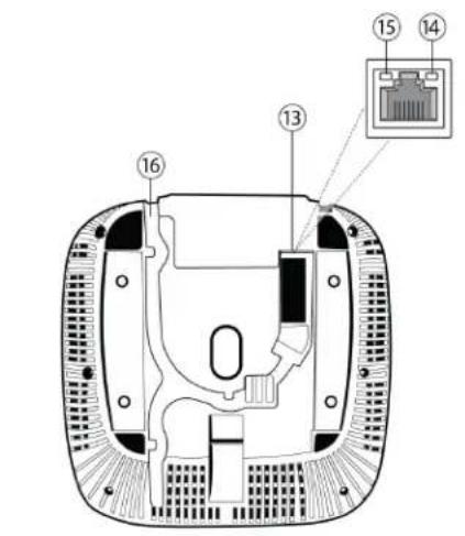
natural_image
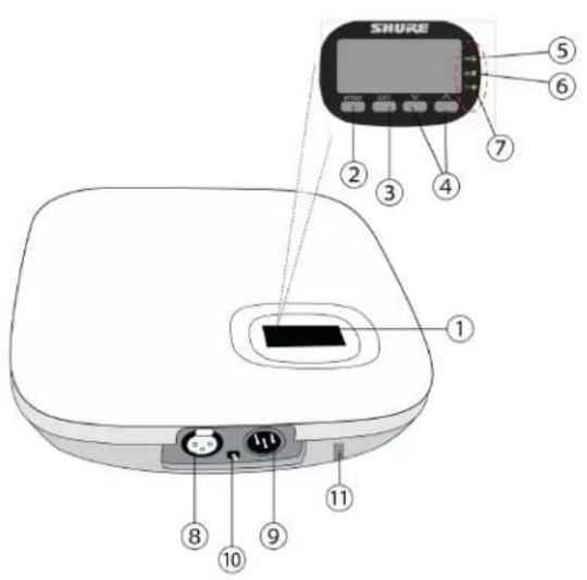
Technical line drawing of a mechanical component with multiple holes and a central hub (no text or symbols)① Display
Shows menu screens and settings.
② Enter Button
Enter a menu or save settings.
③ Exit Button
Return to previous menu screens or cancel setting changes.
④ Arrow Buttons
Scroll to a menu item or make a change to a setting.
⑤ Power LED
| Icon | LED Color | Description |
| PoE | Off | Powered off (disconnected from network or PoE not present on port) |
| Green | Unit is receiving power | |
| Green (flashing) | A system reset is in progress | |
| Amber (flashing) | A network reset is in progress | |
| Green (flashing) + RF LED green (flashing) + Network Audio LED green (flashing) | Simultaneous LEDs: Device identify from the software is in progressAlternating LEDs: Firmware update is in progress |
⑥ Network Audio LED
| Icon | LED Color | Description |
| Off | No Dante channels are routed (receive or transmit). Dante Controller software displays no marks for these channels. | |
| Green | All connected Dante network audio channels are functional (receiving digital audio as expected). Dante Controller software displays green check marks for these channels. | |
| Amber | One or more connected (receiving) Dante network audio channels are experiencing a subscription error, or unresolved (transmitting device is off, disconnected, renamed or has incorrect network setting). Dante Controller software displays yellow triangle marks for these channels. | |
| Amber (flash-ing) | A network reset is in progress | |
| Green (flash-ing) + RF LED green (flashing) + PoE Power LED green (flashing) | Simultaneous LEDs: Device identify from the software is in progressAlternating LEDs: Firmware update is in progress |
⑦ Wireless Audio LED
| Icon | LED Color | Description |
 | Off | No connection or set to RF mute |
| Green | Wireless channel secured and RF/wireless audio connected for 1 or more devices | |
| Amber | Wireless channel selection in progress | |
| Green/ red (flashing) | Detecting wireless interference | |
| Green (flashing) + PoE Pow-er LED green (flashing) +Network Audio LED green (flashing) | Simultaneous LEDs: Device identify from the software is in progressAlternating LEDs: Firmware update is in progress |
⑧ Analog XLR Audio Input
Connect an external output.
⑨ Analog XLR Audio Output
Connect to an external input.
⑩ Ground Lift Switch
Lifts the ground from pin 1 of the XLR connector and the sleeve of the 14 " Audio Output to minimize ground-related noise that can occur when connecting the XLR Audio Output or Input to a third-party device. The ON position of the switch is labeled lift.
⑪ Reset Button (recessed)
Press and hold the reset button for 10 seconds to reset the MXCW system to factory default settings.
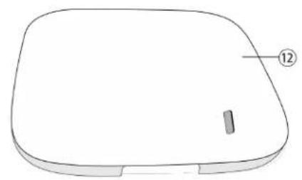
⑫ Access Point Cover
Paint to match the surrounding decor and snap onto the front plate of the device.
The LCD menu and navigation buttons are inaccessible with the cover.
⑬ Ethernet Port
Connect a Cat5e (or higher) cable to a PoE source and the network.
⑭ Ethernet Status LED (Green)
- Off = no network link
• On = network link established - Flashing = network link active
⑮ Ethernet Link Speed LED (Amber)
Off = 10/100 Mbps
- On = 1 Gbps (required for digital audio routing)
⑯ Cable Routing Path
Provides a path for the Ethernet cable to enable a flush-mount.
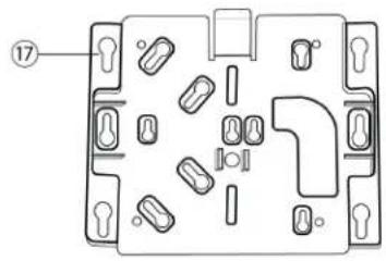
⑰ Mounting Bracket
Allows for optional mounting to a wall, ceiling, or mic stand.
Access Point Menu
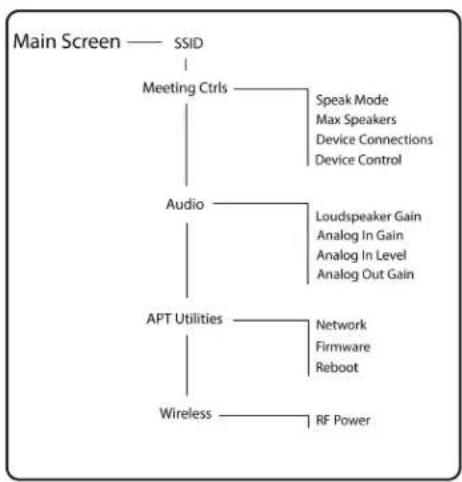
Use the access point menu to monitor and adjust system settings without a computer.
flowchart
graph TD
    A["Main Screen"] --> B["SSID"]
    B --> C["Meeting Ctrls"]
    C --> D["Speak Mode\nMax Speakers\nDevice Connections\nDevice Control"]
    C --> E["Audio"]
    E --> F["Loudspeaker Gain\nAnalog In Gain\nAnalog In Level\nAnalog Out Gain"]
    E --> G["APT Utilities"]
    G --> H["Network\nFirmware\nReboot"]
    G --> I["RF Power"]
    G --> J["Wireless"]
SSID
Select an access point network ID for easy recognition and control of connected conference units. The default SSID is 00.
Meeting Ctrls
| Speak Mode | Select a mode to determine how microphones are activated for participants. |
| Max Speakers | Change the maximum number of delegates and the total speakers. Total speakers includes the number of chairpersons. |
| Device Connections | Determine the access of additional conference units connecting and registering to the network audio. |
| Device Control | Reboot or power off all connected devices. |
Audio
| Loudspeaker Gain | Adjust the loudspeaker gain from a range of -30 dB to 6 dB, or select enter to mute. |
| Analog In Gain | Adjust the input gain from a range of -30 dB to 10 dB, or select enter to mute. |
| Analog In Level | Select line or aux level. |
| Analog Out Gain | Adjust the output gain from a range of -30 dB to 10 dB, or select enter to mute. |
APT Utilities
| Network | Shure Control displays the IP address, Subnet, Gateway, and MAC address of the access point, while Audio Network shows this information for Dante. Set the IP address for each network interface to automatic for an assigned IP address, or manual to edit the IP address. |
| Firmware | Display the access point firmware version and serial number. |
| Reboot | The unit performs a power cycle. |
Wireless
| RF Power | Select the RF coverage level of the access point, or turn it off. |
Conference Unit (MXCW640)
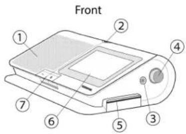
MXCW conference units facilitate communication between participants in group meetings and conferences. The multifunctional units enable participants to speak and be heard with clarity, even in large multilingual events, by combining a gooseneck microphone, loudspeaker, headphone jack, and user controls. For advanced meeting tasks, MXCW conference units include features for voting, managing speakers, and more.
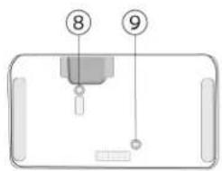
Bottom
① Loudspeaker
Provides a clear audio signal of the floor mix.
② Microphone Connector
Lockable 10-pin microphone connector for MXC gooseneck microphones.
③ Headphone Output
Two TRRS 3.5 mm ports on each side of the unit allow participants to listen to an interpretation channel or the floor audio over headphones.
④ Volume Control
Two knobs on each side increase and decrease audio playback volume for headphones.
⑤ NFC Card Slot
Insert an NFC card to provide participant identification.
⑥ Touchscreen
View and select menu options on the display.
⑦ Microphone Buttons
Press to control the microphone. The buttons are customizable and function differently depending on the participant role and meeting setup. See Using the Conference Units for more details.
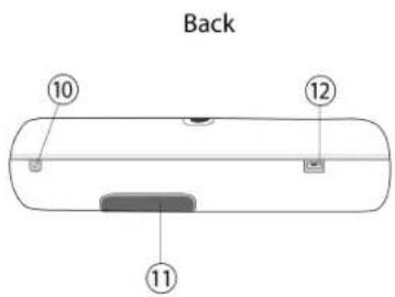
⑧ Power Button
Press and hold to power the unit on or off. The button LEDs on the front of the unit light up red when it is powered on.
⑨ Battery Status Button
Press to check the remaining charge of the battery in the unit.
⑩ TRRS Port
Enables a remote caller to listen and be heard over the floor mix when a cell phone is connected.
⑪ Battery Slot
Insert an SB930 rechargeable battery to power on the unit.
⑫ USB Micro-B Connector
Connect a USB Micro-B cable to charge the battery in the conference unit.
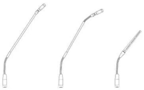
Gooseneck Microphone (MXC416, MXC420, MXC425, MXC406/MS)
MXC-series gooseneck microphones deliver excellent audio performance with a frequency response specifically tailored for speech.
- Commshield® Technology eliminates RF noise
- Single and Dualflex gooseneck options provide flexible positioning
- Locking 10-pin modular connector
• Built-in LED status indicator (LED ring) - Compatible with the Microflex series cardioid, supercardioid, and omnidirectional cartridges
• Available in 16 inch (40 cm), 20 inch (50 cm), and 25 in (63 cm) lengths, as well as the MXC406/MS mini-shotgun microphone
natural_image
Three identical line drawings of a medical or laboratory device with curved ends, no text or symbols present.Securing the Microphone to the Conference Unit
- Insert the microphone into the microphone connector.
- Insert the 1.5 mm hex wrench into the hole next to the microphone on the conference unit and turn counterclockwise.
Using the Conference Units
Once a unit has powered on, tap the touchscreen to access the home screen, or insert a pre-programmed NFC card if available.
Use the navigation pane to move between menus for different options and information on the MXCW640.
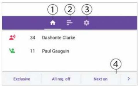
- Home screen: Displays a combined speaker and request list.
- Voting menu (chairperson only): Chairpersons can set up and monitor voting sessions.
- Settings menu: View battery status, hide status bar, change brightness, and change screen language.
- Chairperson control buttons (chairperson only)
Technician Menu
Additional conference unit information and settings are in the technician menu. To access the menu:
- Tap the ⚙ gear icon to enter the settings menu.
- While at the top of the settings page, hold down on both volume control knobs and tap on the right side of the touchscreen.
From this menu you can access 4 different screens to perform the following actions:
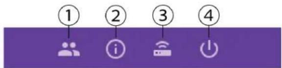
①
- Assign a participant role
- Change the left-button functionality
② i
- Display the firmware version of the conference unit and connected access point
• Factory reset the device - Reboot the device
③
• Display the connected access point SSID
- Disconnect from the access point
④
- Change the startup mode
• Power off the device
Conference Unit Startup Mode
Set the startup mode to determine how MXCW conference units connect to the access point after powering on.
Access the technician menu and choose one of the following startup modes:
| Last Connected (default) | Automatically selects the network it was last connected to before powering down. New or factory default devices use this setting to access the SSID 00 by default. |
| List | Manually choose from a prepopulated list of networks. To update the list with custom names, rename the SSID labels in the web application and push the list to the registered wireless devices. |
| Scan | The device scans for available access point networks and ranks them with strongest signal at top, and weakest at the bottom. Manually select the network from the list. |
Tip: When choosing the network manually, the list indicates the last connected access point with a clock icon.
Lock Conference Unit Power Button
Disable the power button on the bottom of the conference unit to prevent the device from being accidentally powered off. To lock or unlock the power button:
- Open the access point web application and click the wrench icon.
- Go to Global device settings > Advanced permissions > Power button lock.
Customize Welcome Screen
You can upload a custom start-up image to connected MXCW640 devices.
Go to Meeting Controls > Custom welcome screen and upload your image. The image must be 480 by 272 pixels in .png format.
How to Lock the Welcome Screen
You can lock conference units to stay on the welcome screen for units set to the delegate, dual-delegate, or listener roles. This will prevent participants from changing settings on the units, and it will disable the view of speak and request lists. Voting controls are accessible when a voting session is initiated.
- Open the access point web application and click the wrench icon.
- Go to Global device settings > Screen content > Welcome screen lock to lock or unlock the welcome screen.
Conference Unit Buttons
Both hardware buttons on the conference unit are exchangeable, and you can change the left-button functionality depending on the participant role.
To exchange button hardware:
- Insert a thin tool in the gap under the top of the button.
- Twist gently until the button pops out.
- Press the new button into place.
| Left Button Icons |  |  |  |  |  |  |  |
| Right Button Icons |
Note: Go to Accessories to view which buttons can be ordered.
To change the left-button functionality:
• From the conference unit:
- Access the technician menu.
- Assign a role to the conference unit.
- Select the function for the left button of the conference unit.
• From the access point web application:
- Select a device on the devices tab.
- When the device properties panel opens, select the function under the left-button functionality section.
| Name | Description | LED Status | |
| Right-Button Functionality | Speak | Press to be placed on the speak or request list. | Solid red: The microphone is on.Solid green: The participant is placed in the request queue.Flashing green: The request to speak has been denied. |
| Left-Button Functionality | Mute | Press and hold to mute the microphone without removing the right to speak. | Solid blue |
| Mute all (chairperson only) | Press and hold to mute all active speakers without removing the right to speak. | Solid blue | |
| All Del off (chairperson only) | Turn off all delegate microphones. | Solid blue | |
| Next on (chairperson only) | Turn on the first microphone in the request list. | Solid blue | |
| Exclusive (chairperson only) | Press and hold to mute all delegate microphones and activate the chairperson microphone only. | Solid red | |
| Speak (dual delegate only) | Press to be placed on the speak or request list. | Solid red: The microphone is on.Solid green: The participant is placed in the request queue.Flashing green: The request to speak has been denied. |
Rechargeable Battery (SB930)
The SB930 is a smart, lithium-ion rechargeable battery that powers the MXCW640 conference unit. An integrated battery level indicator allows you to quickly check the battery status.
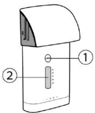
① Battery Status Button
Press the button to check the remaining charge of the battery in the unit.
② LED Status Indicator
Shows battery state when battery status button is pressed.
Battery Life
Different operating and storage conditions can shorten or lengthen battery life. Consider replacing your battery when the battery health is at 80% or less, or after approximately 1200 charging cycles. Battery health percentage and number of charge cycles are available in the charging station web application.
Important Tips for Care and Storage of Shure Rechargeable Batteries
Proper care and storage of Shure batteries results in reliable performance and ensures a long lifetime.
• Always store batteries and transmitters at room temperature
- Ideally, batteries should be charged to approximately 40% of capacity for long-term storage
• Periodically clean the battery contacts with alcohol to maintain ideal contact
- During storage, check batteries every 6 months and recharge to 40% of capacity as needed
Networked Charging Station (MXCWNCS)
The MXCW networked charging station (MXCWNCS) provides charging and storage for up to ten SB930 rechargeable batteries. Installation options include mounting in a rack, to a wall, or on a table surface.
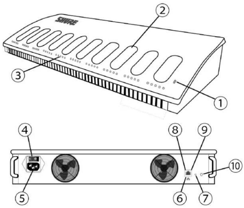
① Status LED
| Indicator | Description | |
| Color | Status | |
| Off | Off | Powered off |
| Green | SolidFlashing | Powered onFactory default reset in progress |
| Amber | Solid | Storage mode enabled |
| Flashing | Network reset in progress | |
② Charging Slots
For charging and storing SB930 batteries.
③ Charging Status LEDs
Each charging slot has 5 LEDs that illuminate to show the battery's charge level:
| LED | % Battery Charge |
| 1 | Flashing: <10%Solid: >10% |
| 2 | >25% |
| 3 | >50% |
| 4 | >75% |
| 5 | >95% |
Charging error details are available in the web application and the full online system guide at pubs.shure.com
④ Power Button
Flip the switch to turn the unit on or off.
⑤ Power Input
Connect to the included power supply.
⑥ Ethernet Port
Connect to an Ethernet network to enable remote monitoring from the web application.
⑦ Reset Button
Press and hold to reset the device to default settings. The length of the button press determines the type of reset:
• Network reset: Press and hold for 4 seconds to reset any network settings and refresh the network connection.
• Factory default settings: Press and hold for 8 seconds to reset the device to factory default settings.
⑧ Ethernet Link Speed LED (Amber)
Off = 10 Mbps
- On = 100 Mbps
⑨ Ethernet Status LED (Green)
- Off = No network link
- On = Network link established
- Flashing = Network link active
⑩ Storage Mode Button
Press to preserve battery health for batteries being stored for an extended period of time.
Powering On the Device
- Connect the device to a power source using the supplied power cable.
- Flip the power switch to turn on the device.
Monitoring Battery Charge
The MXCW power management system combines intelligent, rechargeable technology with a variety of monitoring options for the SB930 batteries.
| In Use | • View remaining battery runtime on in-use microphones from the touchscreen or under the Devicestab in the MXCW system web application. The remaining time is displayed in hours:minutes.• Check the battery LEDs by pressing the battery status button on the bottom of the con-ference unit. |
| Charging | • View the charging status from the charging station web application.• Monitor the LEDs on the charger. |
Icons for Charging Batteries
The following icons appear in the MXCWAPT web application to indicate battery status:
• : Battery charge ≤ 30 minutes
• Battery charge ≤ 1 hour
• ? : Battery minutes are being calculated
• Ψ : Battery is being charged by USB
• ⚠ (flashing): USB cable has insufficient power
Charge Status LEDs
Each charging slot has a row of LEDs that illuminate to indicate the status of the battery. See the networked charging station web application for more details.
| LED Segment | LED State | Description |
| 1 | Green (flashing) | <10% battery charge |
| Green | >10% battery charge | |
| Red (flashing) | Invalid batteryRecovery failedCharge failedCheck batteryCheck chargerBattery read error | |
| Red | Battery coldBattery hot | |
| Green + Amber (alternate flashing) | In recovery | |
| 2 | Green | >25% battery charge |
| 3 | Green | >50% battery charge |
| 4 | Green | >75% battery chargeBattery warm. See web application for details. |
| 5 | Green | <95% battery charge |
Average Charging Times
| Time Charging | Operating Runtime | Capacity |
| 30 minutes | 1 hour | 10% |
| 1.5 hours | 5 hours | 50% |
| 4 hours | >11 hours | 100% |
*based on battery with 100% health
Charging Batteries with USB
Use the USB port on the conference unit to charge the battery during operation. This can be especially useful for long meetings or when backup batteries are not available. The battery status appears as a lightning bolt on the touchscreen when plugged into USB.
When a battery is being charged while the unit is turned off, the charging status shows on the touchscreen. If the battery is fully charged, the conference unit powers off after 10 minutes.
Average Charging Times Using USB
| MXCW640 Power Status | Time Charging | Capacity |
| On | 8 hours | 100% |
| Off | 6 hours : 30 minutes | 100% |
USB Cable Requirements
Use a micro USB cable that can supply at least 2 amps of power to the conference unit.
If an insufficient power supply is plugged in while the conference unit is powered on, the battery status alternates between the status and a warning symbol. If the unit is powered off, the touchscreen shows it is not charging due to an insufficient power supply. The conference unit powers off again after 10 minutes.
Battery Statistics
The charging station web application provides detailed information for each battery in the charger. Sort battery statistics by selecting one of the following statistics from the dropdown:
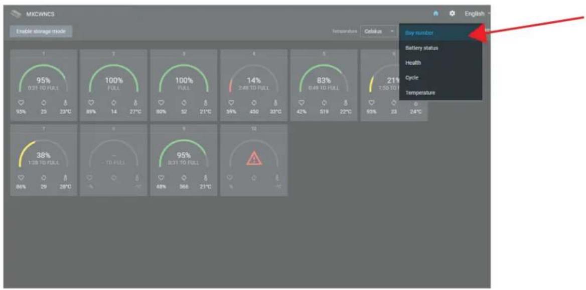
Bay number
Displays the order of the batteries based on which slot they are placed in.
Battery status
Displays charge as a percentage of the total battery capacity. Also shows time remaining to full charge.
Health
Displays health of selected battery as a percentage of the charge capacity of a new battery. Charge capacity (battery life when fully charged) will decline as a result of repeated charge cycles, age, or storage conditions.
Cycle
Displays total number of times that the battery has undergone one full count of discharge and charge. Recharging after discharging halfway counts as one half of a cycle. Recharging after discharging a quarter of the way counts as one quarter of a cycle.
Temperature
Displays battery temperature.
Storing Batteries
Use the MXCW charging station to store batteries for long periods of time (weeks and months). Storage mode protects batteries by storing them at a safe charge level that preserves battery health over time. When you are ready to use the batteries again, simply turn off storage mode and wait for the batteries to fully charge.
- Insert batteries in the charging station.
- Place the charger in storage mode:
• From the hardware: Press and hold the Storage mode button for 5 seconds.
• From the software: Open the charger web application to the home page and turn on storage mode.
Access Point Installation
Best Practices When Selecting a Location for the Access Point
- Direct the face of the access point toward the intended microphone coverage area.
- Position the access point in the same room as the conference units, and with an unobstructed line of sight to the microphones.
- Keep the device away from large metal objects.
- Keep at least eight feet between all access points.
- Mount with the XLR ports accessible, as it may be useful for connecting external equipment.
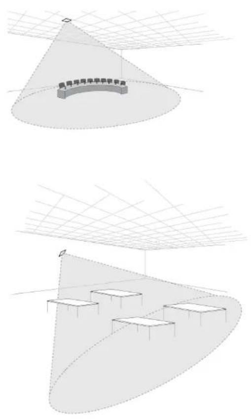
Important: Always perform a "walk around" test to verify coverage before using a wireless system during a speech or performance. Experiment with placement to find the optimum location.
Requirements Checklist
Make sure your equipment meets these requirements before installing the system:
- Use shielded Cat 5e or higher Ethernet cables.
- Use balanced XLR cables for analog input/output.
- Use Gigabit DHCP router to connect multiple access points in the same installation. Ensure it meets the following requirements:
Gigabit ports - Provides Class 0 PoE with at least 6.5 W
• Quality of Service (QoS) with 4 queues
• Diffserv (DSCP) QoS with strict priority - If the router features Energy Efficient Ethernet (or Green Ethernet), ensure it is disabled from the ports dedicated for the system
- Recommended: A managed switch to provide detailed information about the operation of each network link (port speed, error counters, bandwidth used, etc.)
- Limiting cable runs to ≤100 meters between devices.
- Use same firmware version for all devices in your system.
- Ensure MXCW components and the computer are on the same network and set to the same subnet.
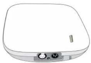
External Cover for Painting
The access point is supplied with an external cover that can be painted to match the decor around the installation. Snap onto the front plate of the device after it has been painted.
natural_image
Simple line drawing of a square electronic device with a button and indicator lights (no text or symbols)Mounting Options
Wall or Ceiling:
- Mark and drill pilot holes using the mounting bracket as a template.
- Secure the mounting bracket to the surface using #8 (4 mm) screws (not included).
- Connect the Ethernet cable to the access point using the cable route path and mount the access point to the bracket.
Electrical Box:
- Pull the Ethernet cable through the electrical box.
- Mount the bracket to the electrical box using #6-32 (3.5/16 mm) screws (not included).
- Connect the Ethernet cable to the access point using the cable route path and mount the access point to the bracket.
Drywall:
- Mark and drill pilot holes using the mounting bracket as a template.
-
Install drywall anchors.
-
Mount the bracket to the drywall anchors using #8 (4 mm) screws (not included).
- Connect the Ethernet cable to the access point using the cable route path and mount the access point to the bracket.
Wood Paneling:
- Mark and drill 3/32" (2 mm) holes using the mounting bracket as a template.
- Mount the bracket to the wall using #8 (4 mm) screws (not included).
- Connect the Ethernet cable to the access point using the cable route path and mount the access point to the bracket.
Ceiling Tile:
Important: Use large fender washers or a large metal plate on the back side of the ceiling tile to support the weight of the access point.
- Mark and drill pilot holes for the screws and cable entrance using the mounting bracket as a template.
- Mount the bracket to the ceiling using #6 (3.5 mm) screws (not included).
- Pull the cable through the hole to connect it to the access point, and mount the access point to the bracket.
Tripod:
Use an adapter to bolt the mounting bracket to a microphone stand or tripod.
Networked Charging Station Installation
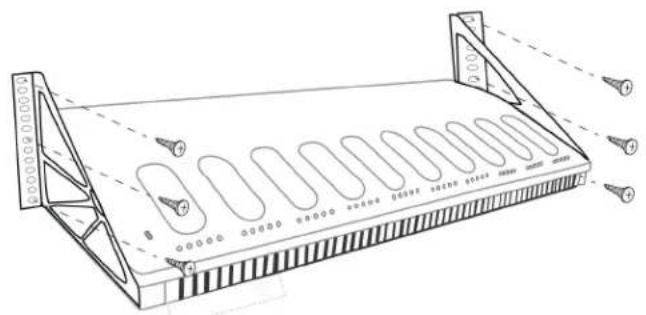
The screws for attaching the mounting brackets to the charger are provided. Screws for securing the charger to another surface are not included.
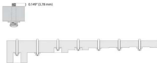
Important: The top of the screw must extend exactly 9/64 (0.149) inches (3.78 mm) above the surface (about 4 12 threads). Screws must be able to support 99.6 oz (2.8 kg) weight of charger.
- Use the screws that best fit the thickness of the surface.
- Use at least 3 screws to secure each mounting bracket to the charger.
- Use at least 3 screws on each side to secure the mounting brackets to the rack or wall.
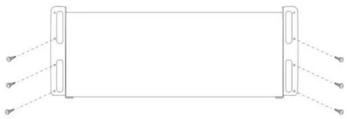
To install the charger:
- Screw the mounting brackets to each side of the charging station.
natural_image
Pure diagram of a rectangular frame with two side panels and three corner connectors, no text or symbols present.Bottom of Networked Charging Station
- Attach the mounting bracket to the rack or wall using the appropriate screws for you surface. Leave room for cabling to the charging station.
Best Practices for Rack Installation
- Ambient temperature in the rack should not exceed specified operating temperature range of the device.
- Keep fan inlet and air vents clear from obstruction and provide adequate space for airflow within the rack.
System Set Up
Maximum System Size
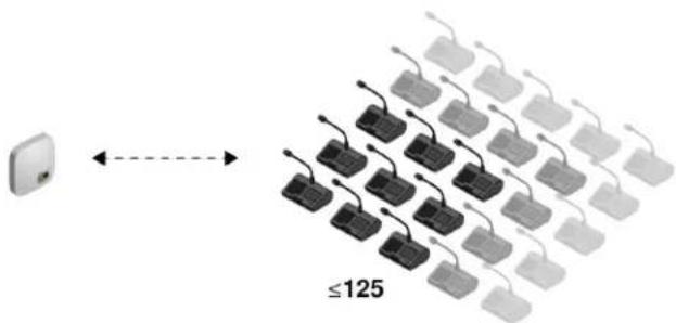
Connect up to 125 MXCW wireless conference units to a single access point. Connected devices operate as a self-contained, encrypted audio system for speaking, listening, and contributing to the meeting.
Wireless Device Network
Setting up wireless MXCW devices is similar to connecting your computer to a wireless network. The MXCW access point acts as the wireless router, broadcasting a network SSID to the wireless devices in range.
The access point includes several customizable network SSIDs that allow you to label MXCW networks for easy recognition and control according to the installation or application. A default network (SSID 00) ensures that new or reset devices automatically connect after powering on.
To add a microphone, simply connect it to the right network.
Connecting Devices for the First Time
MXCW wireless devices automatically connect and register after power up. The default network SSID 00 ensures new or factory reset devices connect automatically to the access point in range.
To connect to an access point network:
- Power on the access point. Wait for it to automatically select the best available wireless channel for operation. When the channel is secured, the access point will broadcast its network (SSID 00) to the wireless MXCW devices.
- Power on the MXCW conference unit. The device automatically scans for the default network.
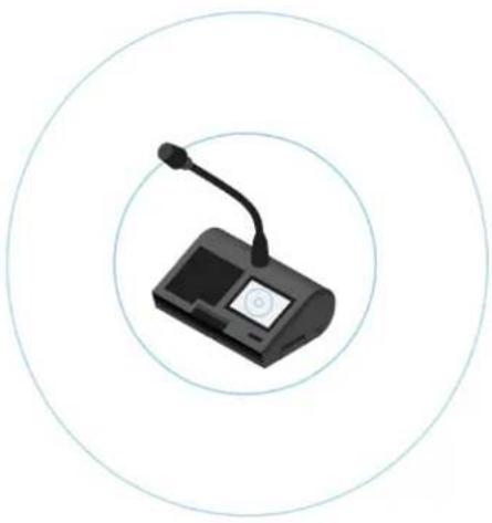
natural_image
Illustration of a handheld electronic device with a microphone, enclosed in concentric circles (no text or symbols)- The default access point network (SSID 00) is selected and the devices are ready for use.
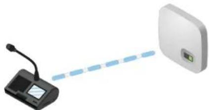
natural_image
Illustration of a desktop microphone connected to a white rectangular device via a blue dashed line (no text or symbols)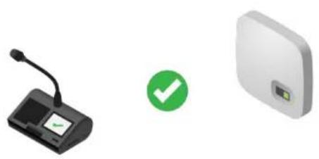
natural_image
Three electronic devices: a desktop microphone, a green checkmark icon, and a white square device (no text or symbols visible)- Add additional microphones until all participants are covered or the system is full.
Restricting New Device Connections
The devices tab in the web application shows which conference units are connected to the SSID network by separating them into 3 groups: online, offline, or unregistered. By default, conference units automatically register once they are connected.
You can add or remove devices from registration. Select a device, open : more options from the device properties panel, and press Deregister to move a device to the unregistered group. Select a device from the unregistered group, then open : more options from the device properties panel and press Register to register a unit.
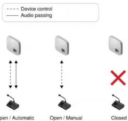
To determine additional device connections, select one of the following options from the dropdown on the Devices tab:
- Open (default): New devices will automatically connect and register.
- Restricted: New devices will connect to the SSID network, but will be on the unregistered list until registered manually.
- Private: No new devices can connect or register to the audio system.
flowchart
graph TD
    A["Device control"] --> B["Open / Automatic"]
    C["Audio passing"] --> D["Open / Manual"]
    E["Closed"] --> F["Open / Manual"]
    G["Device control"] --> H["Open / Automatic"]
    I["Audio passing"] --> J["Open / Manual"]
    K["Device control"] --> L["Open / Manual"]
    M["Audio passing"] --> N["Open / Manual"]
    O["Device control"] --> P["Open / Manual"]
    Q["Audio passing"] --> R["Open / Manual"]
    S["Device control"] --> T["Open / Manual"]
    U["Audio passing"] --> V["Open / Manual"]
    W["Device control"] --> X["Open / Manual"]
    Y["Audio passing"] --> Z["Open / Manual"]
    AA["Device control"] --> AB["Open / Manual"]
    AC["Audio passing"] --> AD["Open / Manual"]
    AE["Device control"] --> AF["Open / Manual"]
    AG["Audio passing"] --> AH["Open / Manual"]
    AI["Device control"] --> AJ["Open / Manual"]
    AK["Audio passing"] --> AL["Open / Manual"]
    AM["Device control"] --> AN["Open / Manual"]
    AO["Audio passing"] --> AP["Open / Manual"]
    AQ["Device control"] --> AR["Open / Manual"]
    AS["Audio passing"] --> AT["Open / Manual"]
    AU["Device control"] --> AV["Open / Manual"]
    AW["Audio passing"] --> AX["Open / Manual"]
    AY["Device control"] --> AZ["Open / Automatic"]
    BA["Audio passing"] --> BB["Open / Automatic"]
    BC["Device control"] --> BD["Open / Automatic"]
    BE["Audio passing"] --> BF["Open / Automatic"]
    BG["Device control"] --> BH["Open / Automatic"]
    BI["Audio passing"] --> BJ["Open / Automatic"]
    BK["Device control"] --> BL["Open / Automatic"]
    BM["Audio passing"] --> BN["Open / Automatic"]
    BO["Device control"] --> BP["Open / Automatic"]
    BZ["Audio passing"] --> CA["Open / Automatic"]
    CB["Device control"] --> CC["Open / Automatic"]
    CD["Audio passing"] --> CE["Open / Automatic"]
    CF["Device control"] --> CG["Open / Automatic"]
    CH["Audio passing"] --> CI["Open / Automatic"]
    CJ["Device control"] --> CK["Open / Automatic"]
    CL["Audio passing"] --> CM["Open / Automatic"]
    CN["Device control"] --> CO["Open / Automatic"]
    CP["Audio passing"] --> CDA["Open / Automatic"]
    CE --> CR["Audio passing"]
    CS["Device control"] --> CT["Open / Automatic"]
    CU["Audio passing"] --> CV["Open / Automatic"]
    CW["Device control"] --> CX["Open / Automatic"]
    CY["Audio passing"] --> CZ["Open / Automatic"]
    DA["Device control"] --> DB["Open / Automatic"]
    DC["Audio passing"] --> DD["Open / Automatic"]
    DJ["Device control"] --> DE["Open / Automatic"]
    DF["Audio passing"] --> DG["Open / Automatic"]
    DH["Device control"] --> DI["Open / Automatic"]
    DJ --> DJ
    DK["Audio passing"] --> DL["Open / Automatic"]
    DV["Device control"] --> DW["Open / Automatic"]
    DX["X"] --> DXB["Dashed Red Cross"]
    DXB --> DXC["X"]
Custom Network SSID Labels
It is recommended to change to a custom wireless network after getting up and running on the default network:
- Recognizable: Provide distinct names for your installation. Useful names correlate to a room or common use of the system (examples: SSID=Training or SSID=3NW)
• Security: Customs SSIDs are less likely to inadvertently connect unwanted wireless microphones.
• Automatic Updates: All connected devices automatically update to match the new network label.
To customize the network SSID label:
- Go to ⚙ Settings > SSIDs.
- Select an SSID and rename it. Choose names (up to 32 characters) that make sense for your installation or use case.
Note: The default SSID 00 is not editable.
- (Optional) Press Push to devices to update the static SSID list on all devices connected to this access point The device startup mode must be set to static list.
Resolving Identical Label Conflicts
If multiple access points share the same SSID and are in range of the devices, the system resolves the conflict by choosing one of the following:
- Last connected access point based on its unique MAC address
- Or if none are recognized, the access point with the strongest RF signal
Separating Networks for Multiple Systems
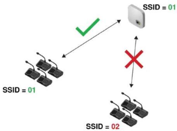
To create separate microphone systems, use multiple access points and set each one to a different SSID. Then connect the conference units to the corresponding network to set up the independent systems.
flowchart
graph TD
    A["SSID = 01"] -->|✓| B["SSID = 01"]
    A --> C["SSID = 02"]
    B --> D["X"]
    C --> D
Multiple networks are useful for installations with adjacent meetings or divisible rooms that can be reconfigured depending on the size and needs of the event.
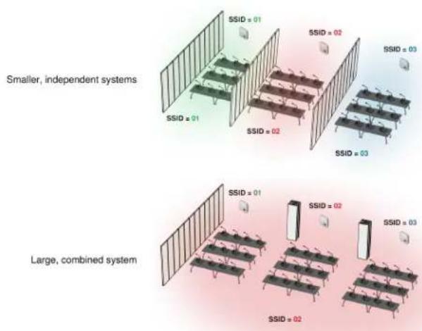
Divisible Room with Multiple System Options
Use different SSIDs to separate conference units into independent systems for smaller events. When the room opens up to support more participants, simply set all conference units to the same access point network to create a large system.
First, set an access point to a different SSID:
- Open the MXCW web application and go to ⚙Settings > SSIDs.
- (Optional) Rename one of the SSIDs network for easy identification, for example: Room C
- Select that network and press Set to confirm the setting.
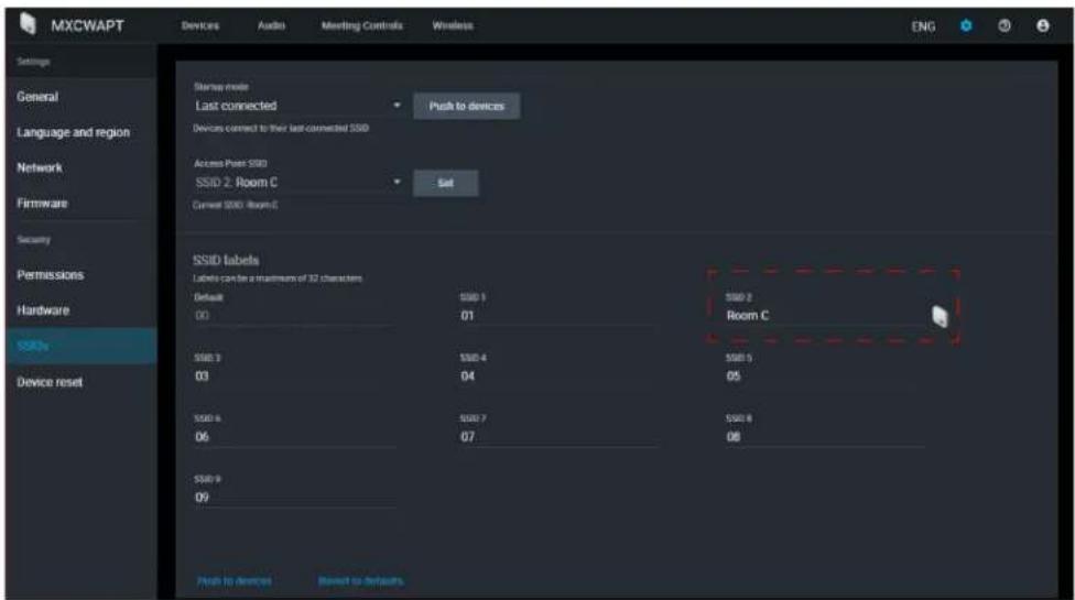
All connected microphones automatically update to the new network.
To update any other devices:
- Open the technician menu on the MXCW640 by tapping the gear icon. While at the top of the page, hold down the volume control knobs and tap the right side of the screen.
- Go to the wireless tab.
- Depending on the Startup mode set on the unit, either scan for a network or view options in the list.
- Choose an access point network and press Connect.
To combine rooms again, simply change the conference units back to the original network to create the larger system.
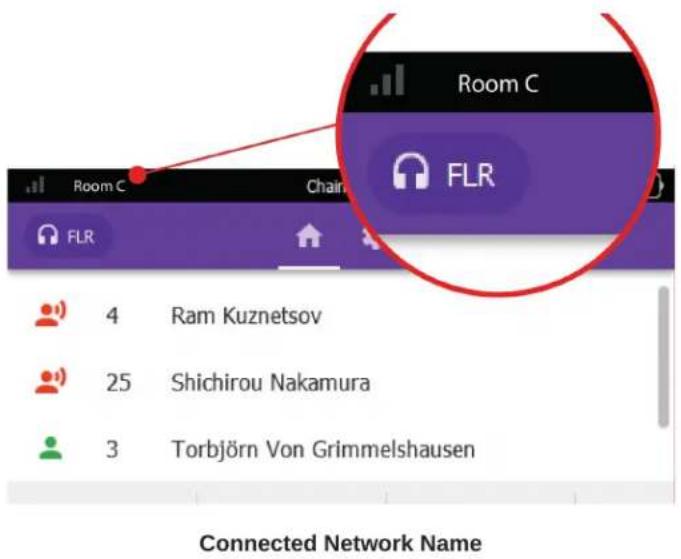
The device displays the connected network from the toolbar.
Web Applications for Monitoring and Control
Web applications provide convenient, remote access to configure, monitor, and control the system. The application is hosted in the device on an embedded webserver and can be accessed using the device IP address or DNS name.
MXCW Web Applications
| Application | Host device | Features |
| MXCW system and meeting control | Access point (MXCWAPT) | Full configuration and control of the MXCW system, devices, participants, and live meetings. |
| Charging batteries | Charging station (MX-CWNCS) | Monitor battery charge and statistics. |
Opening the Device Web Application
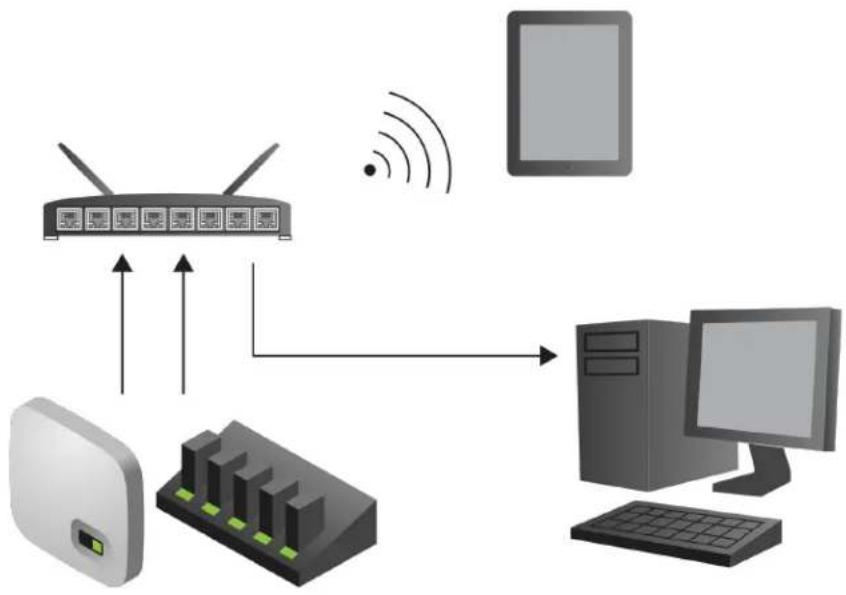
- Connect the computer to the device network.
flowchart
graph TD
    A["Router"] -->|Wireless Signal| B["Desktop"]
    A --> C["Tower"]
    A --> D["Server"]
    style A fill:#f9f,stroke:#333
    style B fill:#ccf,stroke:#333
    style C fill:#cfc,stroke:#333
    style D fill:#fcc,stroke:#333
- Open the Shure Web Device Discovery application. The application lists Shure devices on the network that provide computer control.

- Find the device you want to open:
| Application | Device host |
| MXCW system setup, control, and monitoring | MXCWAPT |
| Batteries currently charging | MXCWNCS |
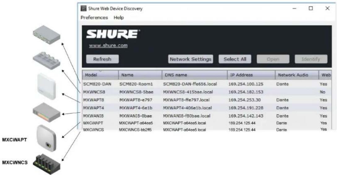
- Double-click the row or right-click to copy the IP address or DNS name to paste into a browser.
Tip: Bookmark the DNS name to bypass the Web Device Discovery application.
Web Browser Requirements
Web applications are supported by the following browsers:
- Google Chrome
- Safari
- Internet Explorer
Using DNS to Open Web Application
You can bypass the Web Device Discovery application by entering the device DNS name into an internet browser. The DNS name is derived from the model of the unit (MXCWAPT or MXCWNCS), in combination with the last three bytes (six digits) of the MAC address, and ending in .local.
Format Example: If the MAC address of a unit is 00:0E:DD:AA:BB:CC, then the link is written as follows:
• MXCWAPT: http://MXCWAPT-aabbcc.local
• MXCWNCS: http://MXCWNCS-aabbcc.local
Web Application Views
The access point web application has dedicated views for specific meeting management tasks.
Open the web application and sign in to the desired view. To have access to all views, sign in as the administrator and select one of the additional views from the user dropdown.
Admin View
This view is for meeting setup and configuration. Use this view to manage Devices, Audio, Meeting Controls, and Wireless settings.
To access this view, do one of the following:
- Sign in as Admin
- Enter the IP address of the access point, followed by /admin
(example: http://192.168.11.137/admin).
Chairperson View
Use the Main tab for microphone control and managing speakers and speak requests during the meeting.
Use the Voting tab to select the voting configuration, view and share the last voting results, and remove certain participants from a voting session.
To access this view, do one of the following:
• Sign in as Chairperson
- Select it from the administrator page
- Enter the IP address of the access point, followed by /chairperson
(example: http://192.168.11.137/chairperson).
Display View
Display view shows the speaker list, request list, and voting results to meeting participants. Use this view to share a screen with the entire meeting space.
To access this view, do one of the following:
- Sign in to Display
- Select it from the administrator or chairperson page
- Enter the IP address of the access point, followed by /display
(example: http://192.168.11.137/display).
Tip: Put the page in full-screen mode during the meeting:
- PC: F11
• Mac: ctrl + cmd + f
Using a Passphrase
The access point web application must have an Admin passphrase created when an access point is powered on for the first time, or after a factory reset. The passphrase may be changed or removed after the system setup is complete.
To change or remove a passphrase, open the ⚙Settings menu in Admin view and select the Permissions tab.
Note: Anyone can access the web application from a computer or mobile device connected to the network when a passphrase is not enabled.
Wireless and RF Management
Microflex Complete Wireless provides automatic, encrypted wireless transmission for up to 125 conference units at a time. The access point scans and selects the best operating channel across the wireless 2.4 GHz and 5 GHz frequency bands, including DFS channels.
Wireless Operating Distance
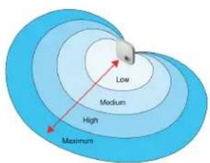
The RF power level determines the operating distance between the access point and conference units. Set the RF power level according to the size of the microphone installation.

flowchart
graph LR
    A["Low 25 ft (7.6 m)"] --> B["Medium 50 ft (15.2 m)"]
    B --> C["High 100 ft (30.5 m)"]
    C --> D["Maximum 150 ft (47.7 m)"]
Variable Operating Distance
Setting RF Power
Select the RF power from the web application by going to Wireless > RF power.
RF Coverage from the Access Point
| Setting | Transmitter Power (mW) | Coverage Distance from APT | Typical Application |
| Maximum (default) | 25 | 150 ft (45.7 m) | Ballroom and auditorium spaces |
| High | 13 | 100 ft (30.5 m) | Large meeting spaces and lecture halls |
| Medium | 5 | 50 ft (15.2 m) | Conference, training and multipurpose rooms |
| Low | 1 | 25 ft (7.6 m) | Small video-conference rooms and boardrooms |
| Mute | 0 | 0 ft (0 m) | Long meeting breaks or access point not in use |
Note: Maximum transmitter power varies by region.
natural_image
3D wireframe model of a helmet with a red arrow pointing to a rectangular object on its surface (no text or symbols)Cardioid RF Pattern
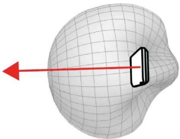
The access point RF pattern is cardioid, picking up equally from the sides to the front cover of the unit.
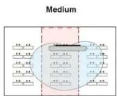
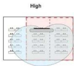
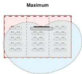
Room Combining Example
Increase RF power levels to cover larger combined rooms.
Reliable Bandwidth Allocation
MXCW easily scales from 2 to 125 conference units without any change in the audio performance. The bandwidth is strategically divided, allocating the uplink channels only for active speakers, while preserving traffic for continuous downlink monitoring channels.
Selecting or Excluding Specific Wireless Channels
You can avoid specific wireless channels by deselecting them from the web application. The MXCW system scans all channels in the 2.4 and 5 GHz spectrum and chooses the cleanest one for operation. After deselecting specific channels, MXCW will no longer scan and operate in those frequencies. At least one non-DFS channel must be selected at all times.
To exclude specific wireless channels:
- Go to the Wireless tab.
- Press Select wireless channels.
- Deselect the channels you do not want to use.
- Press Apply to save your changes.
Interference Detection and Avoidance
The access point has a built-in spectrum analyzer that continuously scans the wireless environment and ranks the best channels for operation. MXCW commonly operates in a specific block of 5 GHz channels that require Dynamic Frequency Selection (DFS) or Doppler weather radar Dynamic Frequency Selection (DDFS). These channels reserve priority for weather, aviation, and military devices.
To avoid interference from priority devices, DFS channels are scanned for 1 minute and DDFS channels are scanned for 10 minutes before the channels are available for use. If interference is detected, the access point changes to a verified backup channel with minimal disruption to the audio performance. Channels with detected interference are unavailable for 30 minutes. After 30 minutes, the system will resume scanning and verifying the channel for use.
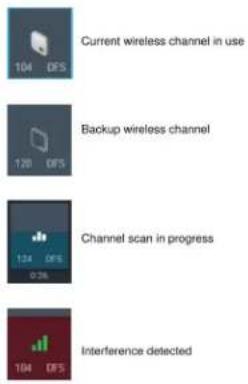
Tips to Improve Wireless System Performance
If you encounter interference or dropouts, try the following suggestions:
-
Check the installation of access point:
-
Ensure a clear line of sight between access point and the conference units.
-
Mount the access point near or above the conference units.
• Make sure people do not block the line of sight between receiver and transmitter. -
Check that other wireless systems are not causing interference:
-
Ensure at least 3 meters (10 feet) between access point and wireless routers, computers, or other active 2.4 GHz or 5 GHz sources.
• Turn on typical wireless devices prior to the event so the MXCW system has time to select a clean channel. -
Avoid heavy wireless traffic activities on nearby networks such as downloading large files or viewing a movie.
-
Additional tips:
-
Make sure the access point is using all available channels (reselect any channels that were manually deselected from the web application).
During sound check, mark trouble spots and position participants away from those areas. - Move access point and microphones away from metal or other dense materials.
Setting the Access Point Country and Region (MXCWAPT-B and MX-CWAPT-W only)
For the MXCWAPT-B and global MXCWAPT-W model variations, the country and region must be set when the unit is powered on for the first time, or after a factory reset. Use the web application or the LCD menu to set the operating location for compliance with local regulations and to get the most reliable scans.
See Access Point Model Variations for the full list of countries and regions for each MXCWAPT model variation.
Changing the Country and Region
Use the web application to change the country and region after the initial setup:
- Go to web application > Language and region and select a new country or region.
- Press Apply to save your changes.
Note: After a change is applied, the access point will reboot and all connected devices will not be able to pass audio during this time. Refresh the browser for the web application after the access point has rebooted.
Setting Up Participants
Participant Roles
The system facilitates meetings in part by adjusting features and permissions based on the role assigned to each participant device. Participant roles affect:
- Speaker limitations: The chairperson can speak at any time, while delegates may need to wait their turn.
- Speak priority: Participants can interrupt another active speaker depending on rank.
- Hardware controls: Button functions depend on the role of the speaker.
For example, since the chairperson is responsible for the meeting, additional controls and permissions are granted to perform additional tasks and to speak at any time without waiting in line. Others are listeners and have minimal speaking permissions.
The following is a summary of the roles in the system:
| Role | Brief description | Details |
| Chairperson | Moderator or leader of the event | The chairperson is a participant with additional permissions for controlling delegate microphones, accessing meeting controls, and overriding delegate speakers at any time. |
| Delegate | Typical participant | Delegates represent the majority of participants in a meeting. Depending on the microphone operation, delegates may need to wait in the request queue until it is their turn to speak. |
| Listener | No microphone required | Participants use the device only to listen to the floor mix (using the loudspeaker) or to an interpretation channel (using headphones). There are no speaking permissions in this role, but a chairperson can turn on this microphone manually. |
| Ambient | Improves audio mix | This role is for spare, utility devices to add natural room ambient noise to the floor mix to aid during pauses in speech or brief breaks between agenda items when no other participants are on the speaker list. There are no listening or speaking permissions in this role.Go to Meetings Controls > Advanced > Enable - ambient microphones. |
| Remote Caller | Delegates can remotely participate in events | Connect a cell phone to a conference unit configured to the remote caller role. A remote caller occupies any of the 8unassigned microphone slots, and remains on the speak list during the event. |
| Dual Delegate | Two delegates share one conference unit | Both the left and right buttons are configured as speak buttons, one for each participant. The speaker list shows both delegates as individual speakers, but only one uplink channel is being used by the shared microphone. Both delegates can cast votes. |
Configuring Conference Units for Remote Callers
- Change a conference unit to the remote caller role in the technician menu or web application.
- Call the remote participant on a mobile device.
- Connect the mobile device to the TRRS jack on the back of the conference unit.
To allow conference units to automatically change to the remote caller role when connecting a mobile device, go to Meeting Controls > Basic and select Auto-sense remote caller role cable.
Speak Priority for Remote Callers
When a mobile device is connected to the conference unit, the remote caller will hear 1 of 3 tones that indicate their connection and speak priority:
- 3 short ascending tones: Connected to the event and remains on the speak list.
• 3 short descending tones: Connected and listening to the event, but no speaking permissions - 2 short repeating tones: Conference unit lost connectivity to the access point
Note: If the conference unit loses power, no tones are sent to the remote caller.
When a microphone slot becomes available, a remote caller can be added to the speak list by unplugging the cable from the conference unit and plugging it in again.
Changing the Participant Role
From the MXCW web application:
- Go to the Devices tab.
- Find and select the participant (or seat) in the list.
- Select the role to expand the dropdown and view additional roles.
- Select the role for that participant. The device reprograms with the corresponding controls and permissions.
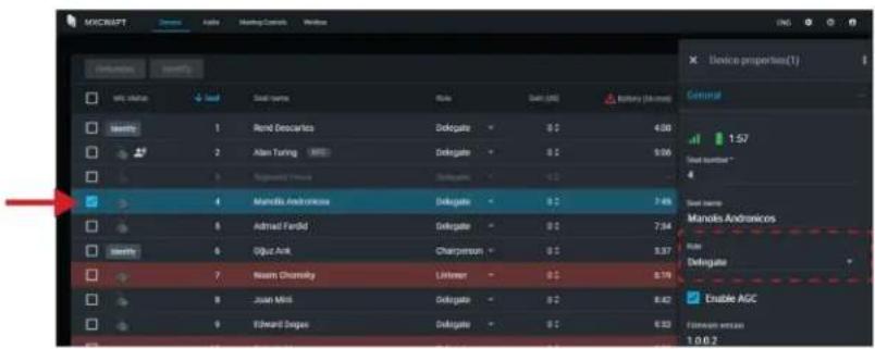
Tip: To update multiple participants at once: select them and change the role from the side properties panel.
From the device technician menu:
- Enter the technician menu on the conference unit.

- From the role tab, select a new role.
Identifying a Device from the Software
Before making changes in the software, confirm you are interacting with the correct hardware.
-
Go to the Devices tab.
-
Click the desired device's icon. The device beeps or flashes to confirm your selection.
Note: Click the wrench icon to change the device identification indicator.
- Select the icon again to stop identifying or wait until it times out (30 seconds).
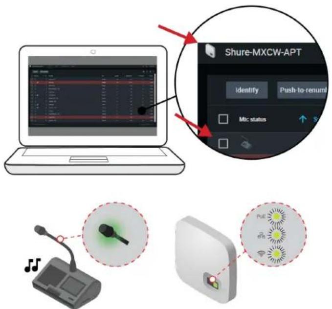
Identify the Hardware
Customizing the Devices Page
Choose which information you want to see from the Devices tab. Edit the that are not useful to your workflow.
filter and visible columns to remove fields
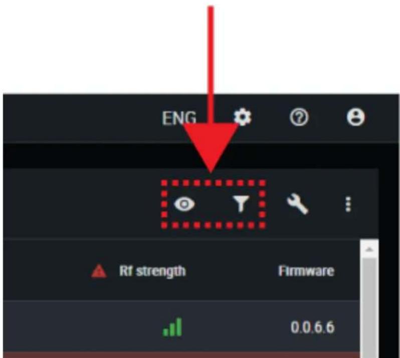
| Visible columns | Determine which columns display in the devices table:Seat numberSeat nameRoleBatteryRF strengthSpeak priorityAudio groupsLeft-button functionalityFirmware versionSerial numberMic gainLow-pass filter (9 kHz)High-pass filter (150 Hz) |
| Filter | Only allow devices with these attributes to display in the devices table:RoleSpeak priorityAudio groupsLeft-button functionalityFirmware version |
To return to default settings, open : more options and select Reset.
Assigning Names and Seat Numbers
The chairperson and meeting operators will need to refer to the participants by either name, seat number, or both. The proper assignment of names and seat numbers is critical to ensure the continuity of the discussion.
When setting up the installation for the first time, each conference unit appears with its default name and an automatically assigned seat number according to the order they were powered on. Use the Devices tab to match wireless devices to the anticipated seating chart.
Note: Devices already display the participant's name if an NFC card is inserted. See NFC Card Functionality for more details.
- Draw a seating chart, or diagram, that represents the room. Number each seat that requires a microphone. Add participant names to the seating chart.
- Provide seat names by clicking the seat name field and writing the new name for each unit.

- Reorder seats to match the actual seat numbers in the room or on your seating chart:
To move a single seat, click in the seat field for that row and enter the new number. If another seat already exists in that number, it will exchange positions with the other seat.
• To move multiple seats, click more options > Push-to-renumber. Enable this mode to rearrange seats by pressing each device's speak buttons in the preferred order. This will remap devices according to the order the buttons are pressed.
Retain Seat Information
Device settings, such as seat name and seat number, are saved during a power cycle by default. To stop saving seat information click the save icon > Disable. Click the save icon > Retain to start saving seat information again.
NFC Card Functionality
Use the free Shure NFC Card Programming application (available on www.shure.com) to program NFC identification cards with the names of meeting participants.
The NFC Card Programming application is designed to work with ACOS3 dual interface or contactless cards, such as the MX-CDualCard. Use the ACR1252U USB card programmer (www.acs.com.hk) to write participant names to the identification cards.
To allow NFC functionality for conference units:
- Go to Meeting Controls > Advanced > Enable NFC.
- Insert an NFC card into the conference unit so participants are identified by their name.
Note: NFC cards are not supported with dual delegate conference units.
Speak Priority
When speaker interruption is enabled, participants can override each other in the speaker list based on their speak priority and their role.
Manually adjust the speak priority of each participant to meet the needs of your meeting.
Example speak priority settings:
| Multiple Chairpersons | Set the highest-ranking chairperson to 5Set the rest of the chairpersons to 4 |
| High-Ranking Delegates | Leave the normal delegates at 1 (default)Set the high-ranking delegates to 2 |
Adjusting Speak Priority
To adjust the speak priority without changing the participant's role:
- Open the web application to the Devices tab.
- Select the participant in the table to open the properties panel.
- Expand the additional properties and adjust the speak priority for that participant.
Active Speaker Interruption
When interruption is allowed, a participant that turns on their microphone will override the last person in the speaker list. The different modes determine the behavior of microphone activation when the speaker list is full.
To change the interruption mode:
- Go to Meeting Controls > Advanced > Active speaker interruption
-
Select a mode:
-
Not allowed
• Higher speak priority allowed (default)
• Equal or higher speak priority allowed
See Speak Priority for information on adjusting individual participants' priority.
Microphone Activation Style
The speak mode determines the way the participants use their microphones in a group setting. Several factors may affect the meeting requirements and the manner in which the meeting is run: room size, number of participants, formality of the event, and availability of technical support staff. The speak mode addresses these factors with presets to control the microphone behavior.
| Mode | Description | How it Works |
| Automatic (default) | Press to speak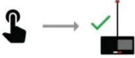 | Speak button turns on participant microphone. There is no request queue: when the speaker list is full, the mic does not turn on. |
| FIFO (First in, first out) | Automatic request queue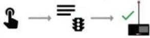 | Speak button adds participant to a queue system. The next microphone in queue turns on automatically once a space is open in the speaker list. Once the speaker list is full, participants are placed into a chronological request queue. |
| Manual | Managed request queue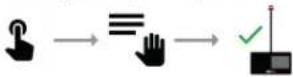 | Speak button adds the participant to a request queue that is managed by the chairperson or operator. |
| Handsfree | Speak into microphone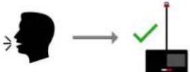 | Microphone turns on automatically when chairperson or delegate speaks. See Handsfree Mode for more information. |
Note: Speak priority may affect the speaker and request lists. A new speaker with higher priority may automatically override the earliest activated microphone if that speaker has a lower priority. See Speak Priority for more details.
Changing the Speak Mode
The speak mode is a system setting that applies to all conference units registered with the access point.
Use one of the following methods to change the speak mode:
- Web application: Meeting Controls > Basic > Speak mode
Note: Chairpersons can also change speak mode from the chairperson view.
- Access point LCD menu: Meeting Ctrls > Speak mode
Handsfree Mode
Conference units use voice detection to turn on the microphone automatically when a chairperson or delegate is speaking into the microphone. Conference units set to dual-delegate and listener roles will not turn on with voice activation. These roles must use the speak button or be activated by the chairperson. Ambient roles will not work in this mode, so use the Last mic stays open feature to add ambient noise to the floor mix instead.
Go to web application > Meeting Controls > Handsfree Mode to change voice detection settings:
- Lower the voice detection threshold to make microphones more sensitive to sound, or raise the threshold to make microphones less sensitive.
- Set the voice detection release time to turn off microphones after so many seconds of silence.
- Select Last mic stays open to keep the last active microphone on.
- Set the room reverberation time to prevent additional microphones from turning on due to reverberation in the room. This may be useful in meeting rooms with many reflective surfaces (glass, concrete, stone, etc.).
- Set the threshold for additional microphone activation to determine how much louder a subsequent participant must speak compared to others before their microphone will turn on.
Best Practices for Handsfree Mode
- Use the active speaker interruption mode sparingly. Avoid Equal or higher speak priority allowed when in handsfree mode.
- Set the maximum number of active speakers and maximum number of active delegates higher than you would for a similar meeting in automatic mode.
- Lower the loudspeaker volume to reduce unintended microphone activation.
Setting the Number of Active Speakers
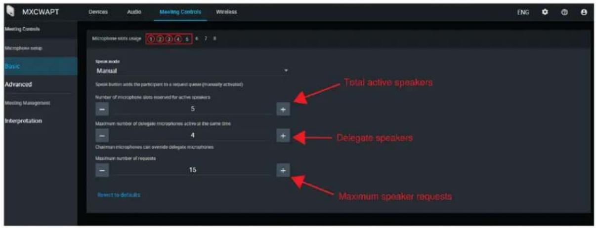
The MXCW system allows up to 8 active speakers. Once the speaker list is full, participants must wait until their turn to speak. If they attempt to speak before their turn, their microphone LED ring flashes momentarily and then turns off as a reminder.
To set the number of speakers:
- Go to Meeting Controls > Basic.
- Use the plus sign (+) and minus sign (−) to change the number of speakers.
• Total: Total number of active delegate and chairperson devices. This is the absolute maximum number of people that can address the floor at the same time.
- Delegate: Number of delegate microphones that can be open at the same time (excludes the chairperson).
• Maximum Requests: Total number of participants that can be in the request queue. This is only available in Manual and FIFO mode.
Best Practices for Setting Active Speakers
- Add an extra participant to the total number of speakers to allow a chairperson to speak at any time.
- When using First In, First Out (FIFO) mode, set the maximum number of speakers to 1 so the participants must wait to speak until another has finished.
- Keep a microphone slot available for a remote caller.
Prevent Speak Button Conflicts
To prevent conflicts of a participant and an administrator or chairperson attempting to perform the same action on a unit:
- Go to Meeting Controls > Advanced > Microphone off permissions.
- Select Prevent double-press of Speak button.
- Set the amount of time (in seconds) for a conference unit to register a second press.
- Optional: Allow a delegate to cancel the administrator or chairperson's speak button press by holding the speak button down for an assigned duration between 1 - 120 seconds.
Changing Participant Microphone Off Permissions
To allow only the administrator or the chairperson to turn off participant microphones:
- Go to Meeting Controls > Advanced > Microphone off permissions.
- Select Only admin/chairperson can turn off participant microphones.
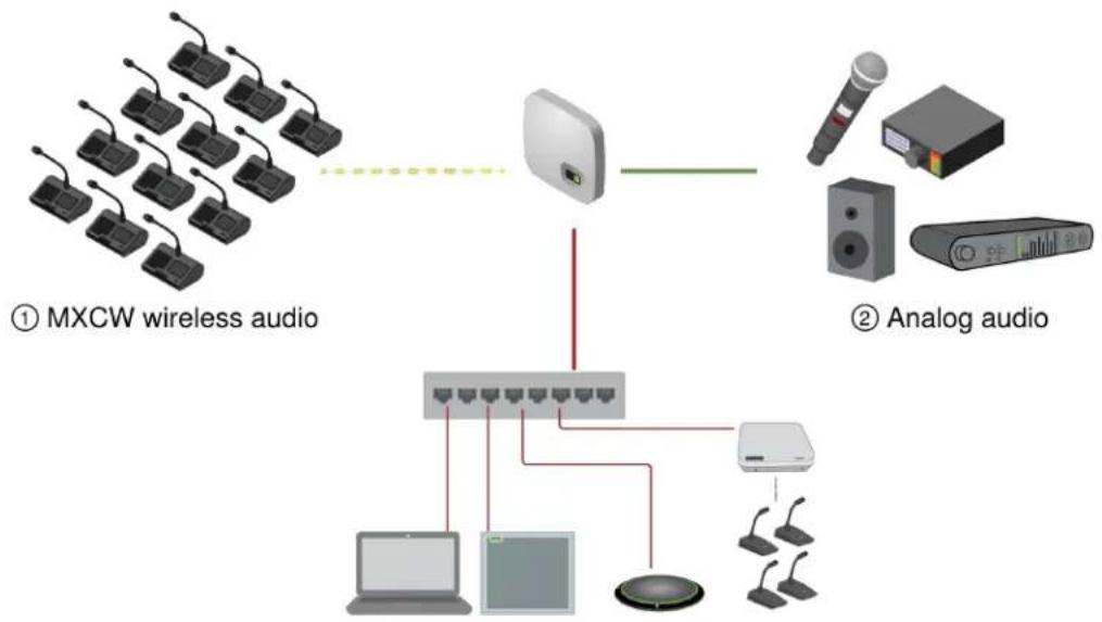
Audio Setup and Channel Routing
The MXCW system supports wireless, analog, and Dante network channels for a wide range of applications and installations. Use the web application to customize the audio system for your meeting.
flowchart
graph TD
    A["① MXCW wireless audio"] --> B["Wireless Device"]
    C["② Analog audio"] --> D["Analog Audio System"]
    B --> E["Network Port"]
    D --> F["Analog Audio System"]
    E --> G["Laptop"]
    E --> H["Laptop"]
    E --> I["Laptop"]
    E --> J["Laptop"]
    E --> K["Laptop"]
    E --> L["Laptop"]
    style A fill:#f9f,stroke:#333
    style C fill:#ccf,stroke:#333
    style B fill:#cfc,stroke:#333
    style D fill:#fcc,stroke:#333
    style E fill:#ffc,stroke:#333
    style F fill:#cff,stroke:#333
    style G fill:#ffc,stroke:#333
    style H fill:#ffc,stroke:#333
    style I fill:#ffc,stroke:#333
    style J fill:#ffc,stroke:#333
    style K fill:#ffc,stroke:#333
③ Dante network audio
MXCW Audio Channels
| 1 MXCW Wireless Network | Encrypted wireless audio between the access point and conference units:8 uplink channels for active speakers9 downlink listening channels (1 floor mix + 8 interpretation channels) |
| 2 Analog audio | XLR connectors on the access point:1 input channel1 output channel |
| 3 Dante network audio | Digital audio channels over the Ethernet network:10 input channels10 output channels |
Once the audio signal is added to the MXCW system, an internal matrix mixer routes audio signals between inputs and outputs, for simple and flexible routing:
- Send the floor mix to multiple outputs for recording, broadcasting, and a spillover listening room.
- Add an external sound source to the floor mix, such as a bodypack microphone for presenters.
- Record each active microphone on a separate audio channel for official record keeping.
MXCW Routing Descriptions
Reference the table for a variety of MXCW routing options.
MXCW Audio Routing Description
| Route | Description | Available channels | Web application path |
| Input channels | Monitor and adjust the signal at each input channel:Audio signalVolume and muteAGC and EQ | 1 Analog input10 Dante inputs | web application >Audio >Inputs |
| Group mixes | 1 or more source(s) for each mix group:Seat numbersInput channels | Floor mix8 group mixes | web application >Audio >Group mixes |
| Output channels | Select source for each output channel:Floor or group mixMicrophone slotInput channels | 1 Analog output10 Dante outputs | web application >Audio >Outputs |
MXCW Wireless Audio
Encrypted wireless audio between the access point and conference units:
| Speaking Channels (Up-link) | 8 uplink channels are provided for active speakers. As participants turn on their microphones, they are added to these channels. Depending on your event, you may want to lower the limit of speakers or add a chairperson role to certain participants.See Setting Up Participants for more information.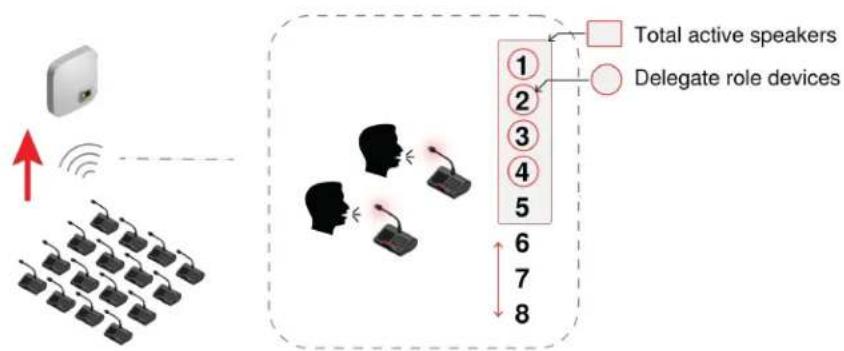 Up to 8 Speakers Up to 8 Speakers |
| Listening Channels (Down link) | 1 fixed Floor channel on speaker and headphones8 assignable interpretation channels on headphone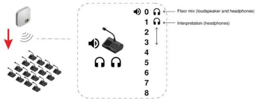 Floor and Interpretation Floor and Interpretation |
The Floor Mix
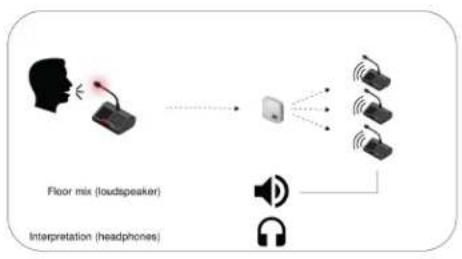
Whenever a microphone is turned on, the audio is routed to the floor mix by default. The floor mix combines all active speakers and sends that signal to the other participant units for listening.
Listen to the floor mix on the unit loudspeaker or the headphone channel.
flowchart
graph LR
    A["Floor mix (loudspeaker)"] --> B["Computer"]
    C["Interpretation (headphones)"] --> B
    B --> D["Sound icons"]
    B --> E["Headphones"]
- Loudspeakers: The floor mix is always the source for the loudspeakers
• Headphones: The floor mix is also available on a headphone channel (Ch. 0)
Monitoring Active Microphones
Use the MXCW system web application to monitor and adjust the microphone slots for audio contributing to the floor mix. Go to Audio > Active microphones.
Analog Connections
Easily connect additional equipment using the XLR analog connectors on the MXCW access point. Common applications include adding a Q&A or presenter microphone, sending audio out to a broadcast feed, or connecting to a teleconferencing system.
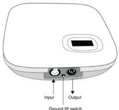
Access Point Analog Connectors
Remove the cover to access the analog connectors
Connecting Analog Devices
-
Connect a line-level audio device:
-
XLR input from a mixer or wireless receiver (default route to floor mix)
-
XLR output to a recording, loudspeaker, or teleconferencing system (default source is floor mix)
-
Perform a sound check using normal speech levels with the rest of the MXCW microphones. For best results:
• Always leave AGC enabled to make sure the signals blends naturally with other MXCW sources
• Use the equalization filters to reduce unwanted sounds like HVAC.
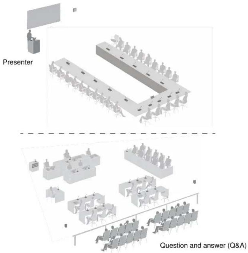
Analog Input Example
Automatic Gain Control (AGC)
Automatic gain control adjusts channel levels to ensure consistent volume for all speakers, in all scenarios. For quieter voices, it increases gain; for louder voices, it attenuates the signal.
For best performance, it is recommended that AGC be enabled for all inputs. This means that all level adjustments will be made automatically by AGC and manual control of input levels using channel faders is inhibited.
If necessary, it is possible to override AGC functionality on a channel-by-channel basis. This may be accomplished by disabling the channel's AGC and then manually adjusting input level with the corresponding channel fader.
Enable or disable AGC in one of the following ways:
- Go to Audio > Active microphones and click the AGC button.
- Select the desired devices from the Devices tab and check the Enable AGC box.
- For analog and Dante inputs, go to Audio > Inputs and click the AGC button.
Adding Other Sources to the Floor Mix
Add other audio sources to blend with the floor mix of MXCW wireless microphones.
• 1 XLR analog input on the access point is automatically routed to the floor
• 10 Dante digital network channels are selectable for routing
- Connect the audio source to the system:
• Analog input: Connect an audio source to the XLR input on the access point.
Tip: Flip the ground lift switch if a buzzing or humming sound occurs because of a ground loop.
• Digital audio: Route audio to one of the MXCW Dante channels using Dante Controller software.
- Ensure the sources are selected on the floor group.
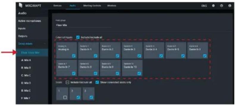
- If necessary, adjust the volume level or EQ to match the other input levels from Audio > Inputs.
Tip: Always use AGC on each channel for automatic, continuous volume optimization.
Removing a Microphone from the Floor
By default, the audio from any active microphone is routed to the floor mix. However, you can remove a conference unit from the floor mix if you do not want it to go to the loudspeakers.
For example, a chairperson's conference unit can be recorded but kept private (taken out of the floor mix). Remove it from the floor mix and route it to another group that is connected to a recording system for archival purposes.
- Go to Audio > Group mixes > Floor.
- Find the seat you want to remove and deselect it.
Tip: Select Show connected seats only to filter out unoccupied seats.
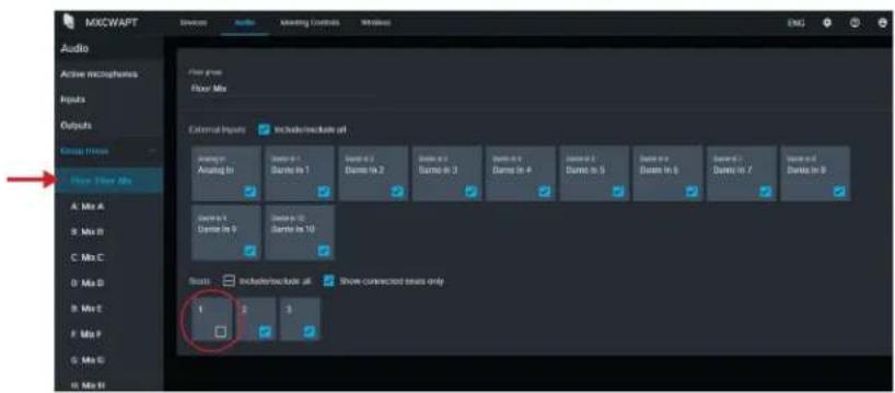
- Route the audio from that seat to another group. Open the desired group and select the seat.
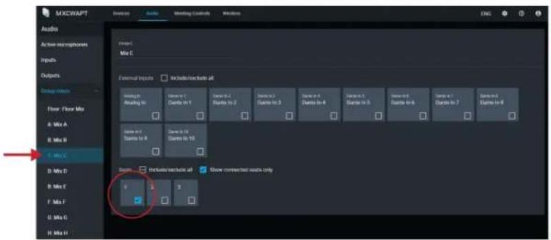
- Select that group as the source for the output channel.
4a. Press Select source
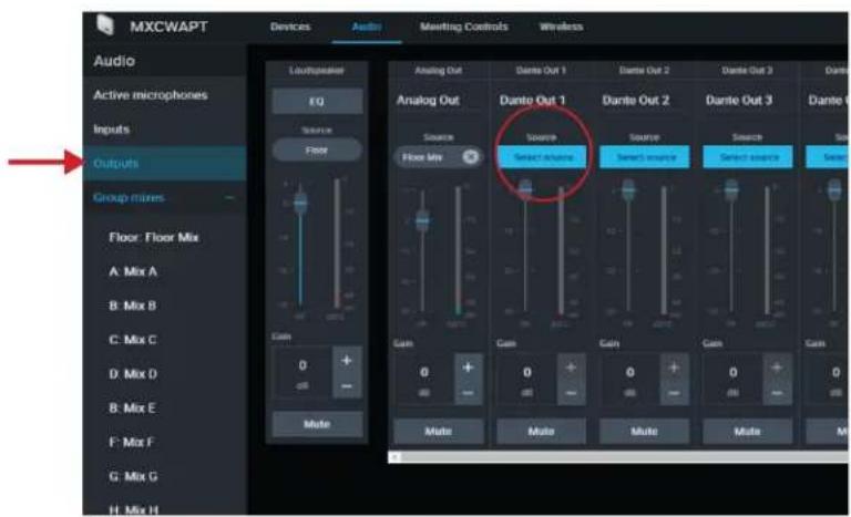
4b. Choose the group mix that the seat is routed to.
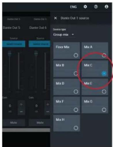
This group (with the seat that was removed from the floor mix) is now routed to the output channel and ready for recording, broadcasting, or another application.
Isolating Participants on Separate Output Channels
8 or Fewer Active Speakers
Assign each participant to their own group mix to record them individually on predetermined channels.
- Open the first group mix (A). Select the first seat. For easy reference, rename the group according that seat.
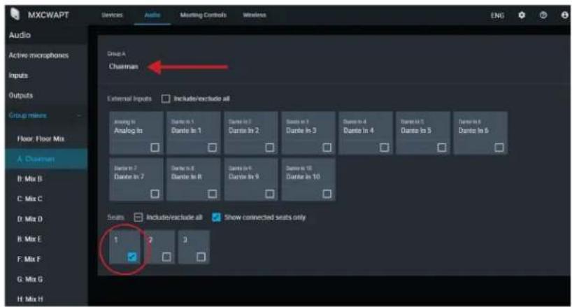
- Repeat for the rest of the group mixes (B - H).
- Open the Outputs tab.
- For the first Dante output channel, select Mix A for the input source.
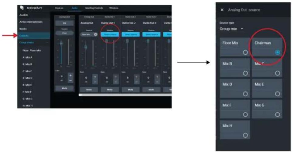
- Repeat for the rest of the outputs.
More than 8 Active Speakers
To record more than 8 active speakers at a time, route the 8 microphone slots (instead of seats routed to mixes) to the output channels.
Keep in mind that the channels will not be permanently assigned to certain participants. The wireless 8 microphone slots 'fill up' starting with slot 1 and increasing with more active microphones. (Slot 1 is always filled whenever a microphone is active.) Therefore this method allows clean recordings, but the labeling will not follow the participants by seat.
- Set the number of active microphones and delegate microphones to 8 (maximum).
- Open the Outputs tab.
- For the first Dante output channel, select Microphone slot 1 for the input source.
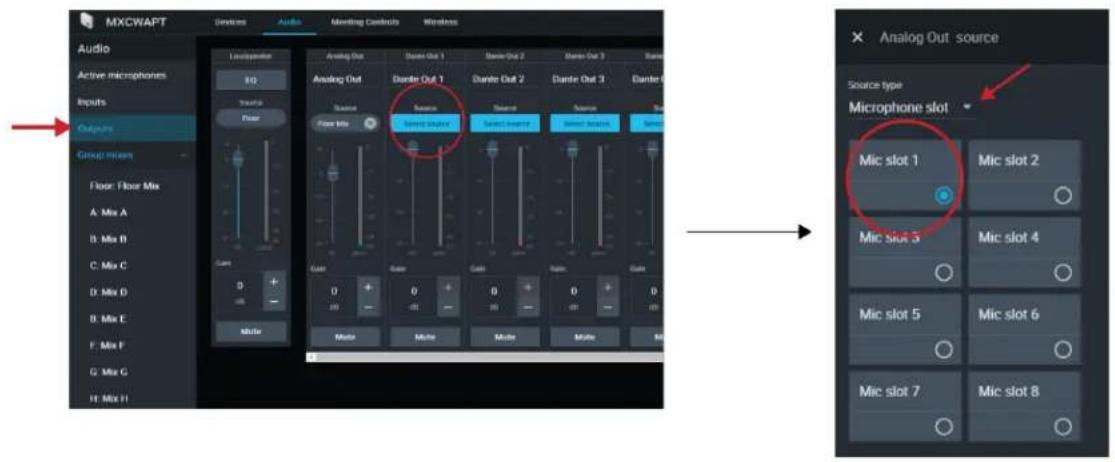
- Repeat for the remaining microphone slots.
Emergency Audio Signal
To prepare for an emergency, connect an Emergency Evacuation Message (EEM) audio signal to the analog XLR input or one of the 10 Dante input channels. The system will detect when the EEM signal is present and distribute it to the loudspeakers and all output connections.
- Go to Audio > Inputs.
- Open the emergency audio dropdown menu and connect the EEM signal to a Dante channel (example: Dante input 1) or the XLR connector on the access point.
Note: Audio returns to normal after being below the threshold for 5 seconds.
Language Interpretation
There are 8 audio channels available for language interpretation. In multilingual meetings, participants speak their native language into the microphone and listen to the interpretation on headphones. Conference units configured to the remote caller role also have access to interpretation channels.
Set Up Interpretation Channels
Use the access point web application to set up interpretation channels for conference units.
- Go to Audio > Interpretation.
- Select the desired language from the dropdown menu.
- Press Assign Source and choose from the available analog input or 10 Dante inputs.
- Click the channel slider to turn the interpretation channel on.
- Repeat the above steps to create up to 8 interpretation channels.
Conference Unit Interpretation Channels
Conference units include a headphone and remote caller output for listening to interpreter channels or other participants on the floor channel. Each participant chooses their channel from the conference unit touchscreen.
Participants select one of the channels to listen to their language during a multilingual event. The audio source comes from the analog input or one of the Dante inputs.
The floor channel is used by interpreters to provide simultaneous interpretation of the discussion. This channel is also selectable by other participants to listen to the floor channel on headphones or in the remote call.
To select headphone channels:
- Connect headphones to a headphone jack on one of the sides of the conference unit.
- Press the 📞 headphone icon on the touchscreen and select a channel from the list.
- Adjust the volume of the headphones using the control knobs on the unit.
To select remote caller channels:
- Connect a mobile device to the TRRS jack on the back of the conference unit.
- Press the phone icon on the touchscreen and select a channel from the list.
Digital Audio Networking
Dante digital audio is carried over standard Ethernet and operates using standard internet protocols. Dante provides low latency, tight clock synchronization, and high Quality-of-Service (QoS) to provide reliable audio transport to a variety of Dante devices. Dante audio can coexist safely on the same network as IT and control data, or can be configured to use a dedicated network.
Dante Network Audio
Connect your Dante audio network to the MXCW system.
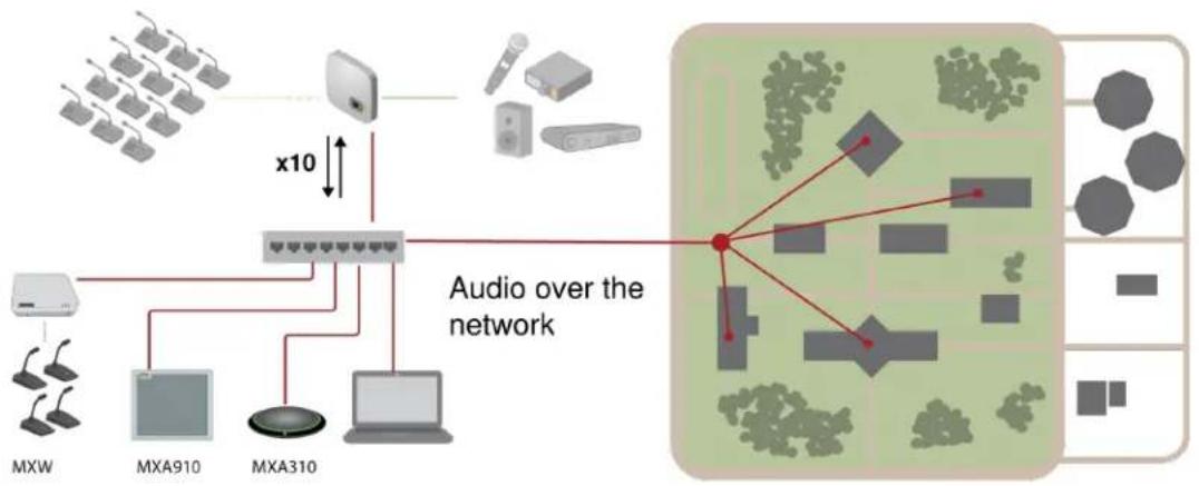
flowchart
graph TD
    A["Device 1"] --> B["Switch"]
    C["Device 2"] --> B
    D["Device 3"] --> B
    E["Device 4"] --> B
    F["Device 5"] --> B
    G["Device 6"] --> B
    H["Device 7"] --> B
    I["Device 8"] --> B
    J["Device 9"] --> B
    K["Device 10"] --> B
    L["Device 11"] --> B
    M["Device 12"] --> B
    N["Device 13"] --> B
    O["Device 14"] --> B
    P["Device 15"] --> B
    Q["Device 16"] --> B
    R["Device 17"] --> B
    S["Device 18"] --> B
    T["Device 19"] --> B
    U["Device 20"] --> B
    V["Device 21"] --> B
    W["Device 22"] --> B
    X["Device 23"] --> B
    Y["Device 24"] --> B
    Z["Device 25"] --> B
    AA["Device 26"] --> B
    AB["Device 27"] --> B
    AC["Device 28"] --> B
    AD["Device 29"] --> B
    AE["Device 30"] --> B
    AF["Device 31"] --> B
    AG["Device 32"] --> B
    AH["Device 33"] --> B
    AI["Device 34"] --> B
    AJ["Device 35"] --> B
    AK["Device 36"] --> B
    AL["Device 37"] --> B
    AM["Device 38"] --> B
    AN["Device 39"] --> B
    AO["Device 40"] --> B
    AP["Device 41"] --> B
    AQ["Device 42"] --> B
    AR["Device 43"] --> B
    AS["Device 44"] --> B
    AT["Device 45"] --> B
    AU["Device 46"] --> B
    AV["Device 47"] --> B
    AW["Device 48"] --> B
    AX["Device 49"] --> B
    AY["MXW"] --> AZ["MXA910"]
    AZ --> BA["MXA310"]
    BA --> BB["MXA910"]
    BB --> BC["MXA310"]
    BC --> BD["MXA910"]
    BE --> BF["MXA910"]
    BF --> BG["MXA310"]
    BH["MXA910"] --> BI["MXA910"]
    BJ["MXA310"] --> BK["MXA910"]
    BL["MXA910"] --> BM["MXA310"]
    BN["MXA910"] --> BO["MXA310"]
    BP["MXA910"] --> BQ["MXA910"]
    BR["MXA310"] --> BS["MXA910"]
    BT["MXA910"] --> BU["MXA310"]
    BV["MXA910"] --> BW["MXA310"]
    BX["MXA310"] --> BY["MXA910"]
    ZM["MXA910"] --> BW
    AAZ["MXA910"] --> BW
    ABV["MXA910"] --> BW
    ACV["MXA910"] --> BW
    ADV["MXA910"] --> BW
    AEV["MXA910"] --> BW
    AFV["MXA910"] --> BW
    AGV["MXA910"] --> BW
    AHV["MXA910"] --> BW
    AIV["MXA910"] --> BW
    AJV["MXA910"] --> BW
    AKV["MXA910"] --> BW
Connect a network of devices
10 input channels, useful for:
- Dante-enabled microphones, such as Microflex ^® Advance ^™ Ceiling and Table Arrays
• Output from an automatic mixer or room system
• Videoconferencing signal of far-end audio
10 output channels, useful for:
• Recording system for archiving
• Live-streaming events
• Videoconferencing feed of near-end audio
Routing Dante Channels
Use the free Dante Controller software by Audinate ^® to route Dante channels in and out of the MXCW system.
Switch Recommendations for Dante Networking
In addition to the basic networking requirements, Dante audio networks should use a Gigabit network switch or router with the following features:
- Gigabit ports
• Quality of Service (QoS) with 4 queues - Diffserv (DSCP) QoS, with strict priority
- Recommended: A managed switch to provide detailed information about the operation of each network link (port speed, error counters, bandwidth used)
QoS (Quality of Service) Settings
QoS settings assign priorities to specific data packets on the network, ensuring reliable audio delivery on larger networks with heavy traffic. This feature is available on most managed network switches. Although not required, assigning QoS settings is recommended.
Note: Coordinate changes with the network administrator to avoid disrupting service.
To assign QoS values, open the switch interface and use the following table to assign Dante ^® -associated queue values.
- Assign the highest possible value (shown as 4 in this example) for time-critical PTP events
- Use descending priority values for each remaining packet.
Dante QoS Priority Values
| Priority | Usage | DSCP Label | Hex | Decimal | Binary |
| High (4) | Time-critical PTP events | CS7 | 0x38 | 56 | 111000 |
| Medium (3) | Audio, PTP | EF | 0x2E | 46 | 101110 |
| Low (2) | (reserved) | CS1 | 0x08 | 8 | 001000 |
| None (1) | Other traffic | BestEffort | 0x00 | 0 | 000000 |
Note: Switch management may vary by manufacturer and switch type. Consult the manufacturer's product guide for specific configuration details.
For more information on Dante requirements and networking, visit www.audinate.com.
Networking Terminology
PTP (Precision Time Protocol): Used to synchronize clocks on the network
DSCP (Differentiated Services Code Point): Standardized identification method for data used in layer 3 QoS prioritization
Dante Network Audio Encryption
Audio is encrypted with the Advanced Encryption Standard (AES-256), as specified by the US Government National Institute of Standards and Technology (NIST) publication FIPS-197.
To activate encryption:
- Open the Settings menu and select Encryption.
- Click Enable Encryption.
Important for encryption to work:
- Encryption must be universally enabled or disabled on all connected Shure devices.
- AES67 must be disabled in Dante Controller to turn encryption on or off.
Networking
Networking Best Practices
Use the following best practices when setting up a network to ensure reliable communication:
- Always use a "star" network topology by connecting each component directly to the switch or router.
- Connect all Shure networked devices to the same network and set to the same subnet. This applies to all devices that audio signals must be routed between (managed through Dante Controller). It is also required in order to open the web application for a device.
• Devices on separate networks require an audio processor or conferencing software to carry audio between them. - Use only 1 DHCP server per network. Disable DHCP addressing on additional servers.
• Power on the switch and DHCP server prior to MXCW equipment.
• To expand the network, use multiple Ethernet switches in a star topology. - All devices must be at the same firmware revision level.
Device IP Settings
Configure IP
Sets IP mode of the selected network interface:
• Auto (DHCP): For automatic assignment of IP addresses.
• Manual (Static): For Static IP addresses.
IP Settings
View and edit the IP Address, Subnet Mask, and Gateway for each network interface.
MAC Address
The network interface's unique identification.
Configuring IP Settings
IP configurations are managed through the web application or the access point LCD screen. By default, they are set to Automatic (DHCP) mode. DHCP mode enables the devices to accept IP settings from a DHCP server, or automatically fall back to Link-Local settings when no DHCP is available. IP addresses may also be manually set.
To configure the IP properties in the web application:
-
Open the web application.
-
Go to Settings and select Network.
-
Select Automatic or Manual. If Automatic is used, addresses will be automatically assigned. See Manually Assigning Static IP Address for Manual setup.
Manually Assigning Static IP Address
To manually assign IP addresses:
-
Open the web application.
-
Go to the Settings tab and select Network.
-
Select Manual as the IP configuration.
-
Enter the IP address, Subnet mask, and Gateway address.
-
Click Apply when finished.
Setting Latency
Latency is the amount of time for a signal to travel across the system to the outputs of a device. To account for variances in latency time between devices and channels, Dante has a predetermined selection of latency settings. When the same setting is selected, it ensures that all Dante devices on the network are in sync.
These latency values should be used as a starting point. To determine the exact latency to use for your setup, deploy the setup, send Dante audio between your devices, and measure the actual latency in your system using Audinate's Dante Controller software. Then round up to the nearest latency setting available, and use that one.
Use Audinate's Dante Controller software to change latency settings.
Latency Recommendations
| Latency Setting | Maximum Number of Switches |
| 0.25 ms | 3 |
| 0.5 ms (default) | 5 |
| 1 ms | 10 |
| 2 ms | 10+ |
Using the Web Application with a Wireless Connection
When operating the web application with a wireless connection, it's important to set up the wireless router properly for best performance. The system employs several standard-based protocols that rely on multicast. The wireless connection treats broadcast and multicast packets differently than general packets for backward compatibility reasons. In some cases, the wireless router will limit the multicast packet transmission rate to a value that is too slow for web application to properly operate.
Wireless routers typically support 802.11b, 802.11a/g, and/or 802.11n standards. By default, many wireless routers are configured to allow older 802.11b devices to operate over the network. In this configuration, these routers will automatically limit the multicast data rates (or sometimes referred to as 'basic rate', or 'management rate') to 1-2Mbps.
Note: A wireless connection can only be used for the control software. Network audio cannot be transmitted over a wireless connection.
Tip: For larger wireless microphone configurations, it's recommended to increase the multicast transmission rate to provide adequate bandwidth.
Important: For best performance, use a wireless router that does not limit the multicast rate to 1-2 Mbps.
Shure recommends the following wireless router brands:
- Cisco
- Linksys
- Apple
IP Ports and Protocols
Shure Control
| Port | TCP/UDP | Protocol | Description | Factory De-fault |
| 21 | tcp | FTP | Required for firmware updates (otherwise closed) | Closed |
| 22 | tcp | SSH | Secure Shell Interface | Closed |
| 23 | tcp | Telnet | Not supported | Closed |
| 68 | udp | DHCP | Dynamic Host Configuration Protocol | Open |
| 80* | tcp | HTTP | Required to launch embedded web server | Open |
| 443 | tcp | HTTPS | Not supported | Closed |
| 161 | tcp | SNMP | Not supported | Closed |
| 162 | tcp | SNMP | Not supported | Closed |
| 2202 | tcp | ASCII | Required for 3rd party control strings | Open |
| 5353 | udp | mDNS^† | Required for device discovery | Open |
| 5568 | udp | SDT^† | Required for inter-device communication | Open |
| 8023 | tcp | Telnet | Debug console interface | Closed |
| 8180 | tcp | HTML | Required for web application | Open |
| 8427 | udp | Multcast SLP^† | Required for inter-device communication | Open |
| 64000 | tcp | Telnet | Required for Shure firmware update | Open |
Dante Audio & Controller
| Port | TCP/UDP | Protocol | Description |
| [319-320]* | udp | PTP^† | Dante clocking |
| 2203 | udp | Custom | Required for packet bridge |
| 4321, 14336-14600 | udp | Dante | Dante audio |
| [4440, 4444, 4455]* | udp | Dante | Dante audio routing |
| 5353 | udp | mDNS^† | Used by Dante |
| [8700-8706, 8800]* | udp | Dante | Dante Control and Monitoring |
| 8751 | udp | Dante | Dante Controller |
| 16000-65536 | udp | Dante | Used by Dante |
*These ports must be open on the PC or control system to access the device through a firewall.
^ These protocols require multicast. Ensure multicast has been correctly configured for your network.
AES67
AES67 is a networked audio standard that enables communication between hardware components which use different IP audio technologies. This Shure device supports AES67 for increased compatibility within networked systems for live sound, integrated installations, and broadcast applications.
The following information is critical when transmitting or receiving AES67 signals:
- Update Dante Controller software to the newest available version to ensure the AES67 configuration tab appears.
- Before turning encryption on or off in the Shure device's web application, you must disable AES67 in Dante Controller.
- AES67 cannot operate when the transmit and receive devices both support Dante.
| Shure Device Supports: | Device 2 Supports: | AES67 Compatibility |
| Dante and AES67 | Dante and AES67 | No. Must use Dante. |
| Dante and AES67 | AES67 without Dante. Any other audio networking protocol is acceptable. | Yes |
Separate Dante and AES67 flows can operate simultaneously. The total number of flows is determined by the maximum flow limit of the device.
Sending Audio from a Shure Device
All AES67 configuration is managed in Dante Controller software. For more information, refer to the Dante Controller user guide.
- Open the Shure transmitting device in Dante Controller.
- Enable AES67.
- Reboot the Shure device.
- Create AES67 flows according to the instructions in the Dante Controller user guide.
Receiving Audio from a Device Using a Different Audio Network Protocol
Third-party devices: When the hardware supports SAP, flows are identified in the routing software that the device uses. Otherwise, to receive an AES67 flow, the AES67 session ID and IP address are required.
Shure devices: The transmitting device must support SAP. In Dante Controller, a transmit device (appears as an IP address) can be routed like any other Dante device.
Voting
The chairperson controls voting sessions from the conference unit or the voting tab in the chairperson web application view. Use the web application to customize voting session settings, such as:
- Enter a vote subject that will appear above the voting buttons and results, if desired
- Exclude participants from the voting session, if desired
- Choose 1 of the 6 voting configurations
To start a voting session:
- Choose a voting configuration.
- Press Start.
-
Press Stop to end the voting session.
-
A voting screen displays on all conference units, and participants with voting rights can cast their votes using the touchscreen.
Voting Configurations
In an open vote a participant's selection remains visible and interim vote results are shown.
In a secret vote there is no visible indication of how a participant voted and interim vote results are not shown.
| Voting Configuration | Conference Unit Screen |
| 2-Button (Open)2-Button (Secret)A 2-Button vote allows the participant to select either “Yes” or “No.” |   |
| 3-Button (Open)3-Button (Secret)A 3-Button vote adds the option to select “Abstain”, which is to formally decline to vote. |    |
| 5-Button (Open)5-Button (Secret)A 5-Button vote allows the user to answer on a scale from “- -” to “+ +.” These responses can be used to respond to a poll. |  |
Voting Results
The results of open voting sessions display after a vote has finished. Chairpersons can share secret voting results by pressing Share from the conference unit or web application. Select Export from the web application to print, save a PDF file, or save a CSV file.
Important: Vote results can't be recalled, printed, or exported after the next vote starts or the results have been cleared.
Note: Results may not always add up to 100 percent due to decimal rounding.
System Maintenance and Troubleshooting Troubleshooting
Basic System Check
Check your system for the following basic hardware and connections:
• Devices are receiving power and are turned on
• Cables are connected
• Devices are on the same network
Wireless Interference
| Select more wireless channels | If any wireless channels are deselected, add them back to the wireless scan in the web application: Wireless > Select wireless channels. |
| Adjust RF power | Lower the RF power in the web application: Wireless > RF power.This improves signal-to-noise ratio but does not eliminate the interference. Go to the web applicaton: Wireless > RF power. |
| Relocate the MXCW access point | Move the access point to another point in the room. See Installation for more details. |
Resetting Devices
Shure devices are designed to work together right out of the box. Prior to a new installation, or during troubleshooting, it may be useful to reset devices to ensure system compatibility.
The system provides 2 reset levels to choose from:
• Network reset: Clears only network settings and provides a fresh network connection.
- System reset: Clears all device and system settings to reset the device to default factory settings.
From the Hardware
| Access Point | Press and hold the recessed reset button.·Network reset:Press and hold for 5 seconds to reset any network settings and refresh network connection.·System reset:Press and hold for 10 seconds to reset the device to default factory settings.See Access Point Transceiver (MXCWAPT) for more details on LED behaviors during a reset. |
| Conference Units | 1. Access the technician menu by tapping the gear icon. While at the top of the settings page, hold down the volume control knobs and tap the right side of the screen.2. Go to the information screen and tap Factory reset. |
| Networked Charging Station | Press and hold the recessed reset button.·Network reset:Press and hold for 4 seconds to reset any network settings and refresh network connection.·System reset:Press and hold for 8 seconds to reset the device to default factory settings. |
From the Software
| Access Point |  Go to ____ Settings > Device reset. SelectReboot device or Restore factory defaults. Go to ____ Settings > Device reset. SelectReboot device or Restore factory defaults. |
| Conference Units | Go to Devices and select a device. From the device properties panel, openmore options and select Factory reset. |
Networked Charging Station

Go to
ry defaults.
Settings > Device reset. Select Reboot device or Restore facto-
Export Log Files
Log files provide important device and network activity information. Go to ⚙ Settings and click Download APT logs to send the log files to Shure Systems Support for troubleshooting.
Firmware
Firmware Updates
Firmware is embedded software in each component that controls functionality. Periodically, new versions of firmware are developed to incorporate additional features and enhancements. You can install firmware using Shure Update Utility.
Download Shure Update Utility at shure.com.
Update Firmware for Conference Units
- Upload MXCWAPT and MXCW640 firmware updates to the MXCWAPT using the Shure Update Utility tool.
- Go to the web application > Settings > Firmware.
- Select the desired conference units.
Note: A minimum of 20 minutes of battery charge is required for firmware updates.
- Click Update.
Firmware Versioning
When updating firmware, update all hardware to the same firmware version to ensure consistent operation.
The firmware of all devices has the form of MAJOR.MINOR.PATCH (e.g., 1.2.14). At a minimum, all devices on the network, must have the same MAJOR and MINOR firmware version numbers (e.g., 1.2.x).
Using a Third-Party Control System
The access point and networked charging station connect to external control systems such as AMX or Crestron via the Ethernet. These devices receive logic commands over the network. Many parameters controlled through the web application can be controlled through a third party control system, using the appropriate command string. Use only one controller per system to avoid messaging conflicts. For a comprehensive list of command strings, visit pubs.shure.com.
- Connection: Ethernet (TCP/IP; select "Client" in the AMX/Crestron program)
- Port: 2202
Accessories
Gooseneck Microphones
| Mini-shotgun gooseneck microphone for MXC and MXCW | MXC406/MS |
| Cardioid gooseneck microphone for MXC and MXCW | MXC416/C |
| Dualflex, cardioid gooseneck microphone for MXC and MXCW | MXC416DF/C |
| Cardioid gooseneck microphone for MXC and MXCW | MXC420/C |
| Dualflex, cardioid gooseneck microphone for MXC and MXCW | MXC420DF/C |
| Cardioid gooseneck microphone for MXC and MXCW | MXC425/C |
| Dualflex, cardioid gooseneck microphone for MXC and MXCW | MXC425DF/C |
Optional Accessories and Replacement Parts
| Dual-Card for MXC, MXCW, and DCS; Quantity 10 | MXCDUALCARD-10PK |
| Chairperson button set for MXCW640; Includes 1 of each: All Delegates Off, Mute All, Next On; Quantity 3 | MXCW-ACC-CM |
| A and B buttons for MXCW640; Quantity 10 each | MXCW-ACC-A/B |
| Mute button for MXCW640; Quantity 10 | MXCW-ACC-M |
| Reply button for MXCW640; Quantity 10 | MXCW-ACC-RPY |
| MXCWAPT mounting bracket | 65A26027 |
Access Point Model Variations
| Region | Model |
| United States | MXCWAPT-A |
| Canada and Mexico | MXCWAPT-B |
| Japan | MXCWAPT-JP |
| Israel | MXCWAPT-IL |
| Worldwide | MXCWAPT-W |
The MXCWAPT-W access point can be set to the following countries and regions:
MXCWAPT-W
| Regions | Countries |
| APAC (Asia Pacific) | Australia, China, Hong Kong, India, Indonesia, Malaysia, New Zealand, Pakistan, Philippines, Singapore, South Korea, Taiwan, Thailand, Vietnam |
| Africa | Egypt, Ethiopia, Kenya, Morocco, Nigeria, South Africa |
| Americas | Argentina, Brazil, Chile, Colombia, Costa Rica, Dominican Republic, El Salvador, Guatemala, Jamaica, Panama, Peru, Uruguay, Venezuela |
| EME | Austria*, Belgium*, Bulgaria*, Croatia*, Cyprus*, Czech Republic*, Denmark*, Estonia*, Finland*, France*, Germany*, Greece*, Hungary*, Iceland*, Ireland*, Italy*, Latvia*, Liechtenstein*, Lithuania*, Luxemburg*, Malta*, Netherlands*, Norway*, Oman, Poland*, Portugal*, Qatar, Romania*, Russia, Saudi Arabia, Slovakia*, Slovenia*, Spain*, Sweden*, Switzerland*, Turkey, UAE, United Kingdom* |
* part of the European Union/EFTA listing in the web application and LCD menu.
Networked Charging Station Model Variations
All include power cable unless otherwise noted.
| Region | Model |
| United States | MXCWNCS-US |
| Argentina | MXCWNCS-AR |
| Brazil | MXCWNCS-BR |
| Europe | MXCWNCS-E |
| United Kingdom | MXCWNCS-UK |
| Japan | MXCWNCS-J |
| China | MXCWNCS-CHN |
| Korea | MXCWNCS-K |
| Taiwan | MXCWNCS-TW |
| Australia | MXCWNCS-AZ |
| India | MXCWNCS-IN |
Specifications
System
Latency
| Microphone Input to Speaker/Headphone Output | 16 ms |
| Microphone Input to Analog Output | 9.2 ms |
| Analog Input to Speaker/Headphone Output | 7.7 ms |
Frequency Response
| Headphone Output | 100 Hz-20 kHz (+0.5 dB/-3 dB) |
| Speaker Output | 220 Hz-15 kHz (±10 dB) |
Total Harmonic Distortion
| Headphone Output | 0.06%, typical |
| Speaker Output | 1%, typical |
Dynamic Range
| Headphone Output | 100 dB (A-weighted), 97 dB (Unweighted), typical |
| Speaker Output (unweighted), typical | 94 dB (A-weighted), 91 dB (Unweighted), typical |
Digital Signal Processing
24-bit, 48 kHz
Audio Polarity
Positive pressure on MXCW640 microphone diaphragm produces positive voltage on pin 2 of MXCWAPT XLR output
Working Range
8 m (Low), 15 m (Medium), 30 m (High), 45 m (Maximum)
Line-of-sight to the MXCWAPT. Actual range depends on RF signal absorption, reflection, and interference.
Security
AES Encryption (Dante and 802.11 a, g)
MXCWAPT
Analog Input
Maximum Input Level
| Line | 24.9 dBV |
| Aux | 10.3 dBV |
1% THD+N, Dante Output
Frequency Response
| Line | 22 Hz-20 kHz (+0.5 dB/-3 dB) |
| Aux | 22 Hz-20 kHz (+0.5 dB/-3 dB) |
Measured at Dante Output
Total Harmonic Distortion
| Line | 0.03%, typical |
| Aux | 0.02%, typical |
Measured at Dante Output
Dynamic Range
| Line | 115 dB (A-weighted), 113 dB (Unweighted), typical |
| Aux | 112 dB (A-weighted), 110 dB (Unweighted), typical |
Measured at Dante Output
Preamplifier Equivalent Input Noise (EIN)
| Line | -92 dBV (A-weighted), typical |
| Aux | -104 dBV (A-weighted), typical |
Input Impedance
| Line | 10 kΩ |
| Aux | 12 kΩ |
Configuration
Balanced
Type
Pin Assignments
Standard XLR Pinout
1=ground, 2=audio +, 3=audio -
GND Lift
| Left | Pin 1=GND Connected |
| Right | Pin 1=GND Disconnected |
Analog Output
Maximum Output Level
4.3 dBV
1%THD+N
Frequency Response
1 Hz- 20 kHz (+0.5 dB/-3 dB
Audio Injected at Dante Input
Total Harmonic Distortion
0.01%, typical
Audio Injected at Dante Input
Dynamic Range
100 dB (A-weighted), 97 dB (Unweighted), typical
Audio Injected at Dante Input
Load Impedance
600 Ω, typical
Type
3-pin male XLR
Pin Assignments
Standard XLR Pinout
1=ground, 2=audio +, 3=audio -
GND Lift
| Left | Pin 1=GND Connected |
| Right | Pin 1=GND Disconnected |
RF
WLAN Standard
IEEE 802.11 a, g
Frequency Bands
2.4 GHz ISM, 5 GHz UNII
Sensitivity
-80 dBm at 10% PER
Output Power
1 mW (Low), 5 mW (Medium), 13 mW (High), 25 mW (Maximum)
Antenna Type
Proprietary Internal Bi-level Dual-band (PIFA), patent pending
Power
Supply Type
Power over Ethernet (PoE)
Supply Voltage
37-57 V
Power Consumption
12.95 Wmaximum, 6.5 Wtypical
Network
Interface
Gigabit Ethernet, Dante digital audio
Link Speed
10/100/1000Mbps
Network Addressing Capability
DHCP or Manual IP address
Cable Length
100 mmaximum
Cable Type
Cat 5e or higher
Connector Type
RJ45
Display
Type
Monochrome FFSTN LCD
Display Size
1.84 x .074 in. (46.7 x 18.8 mm)
Display Resolution
152 x 78 (78 ppi)
Mechanical
Dimensions
47.8 x 242.5 x 241.8 mm (1.88 x 9.55 x 9.52 in.)
Weight
1.15 kg
Housing
Molded Plastic, Die-casted Aluminum
Mounting Type
Ceiling bracket or wall
Environmental
Operating Temperature Range
-7°C (19.4°F) to 49°C (120.2°F)
Storage Temperature
-29°C (-20.2°F) to 60°C (140°F)
Relative Humidity
<95%
MXCW640
Microphone Input
Nominal Input Level
-60 dBV
Maximum Input Level
-1.5 dBV
Measured at Dante Output
Frequency Response
20 Hz - 20 kHz (+0.5 dB/-3 dB)
Measured at Dante Output
Total Harmonic Distortion
0.04%, typical
Measured at Dante Output
Dynamic Range
112 dB A-weighted, 110 dB Unweighted, typical
Measured at Dante Output
Preamplifier Equivalent Input Noise (EIN)
-117 dBV A-weighted, typical
Input Impedance
26 kΩ
Configuration
Unbalanced
Type
Multipin Female Gooseneck Socket
Pin Assignments
Proprietary Shure Pinout
Remote Caller Input
Maximum Input Level
1.6 dBV
Measured at Dante Output
Frequency Response
30 Hz- 20 kHz (+0.5 dB/-3 dB
Measured at Dante Output
Total Harmonic Distortion
0.07%, typical
Measured at Dante Output
Dynamic Range
95 dB A-weighted, 93 dB Unweighted, typical
Measured at Dante Output
Preamplifier Equivalent Input Noise (EIN)
-106 dBVA-weighted, typical
Input Impedance
3.5 Ω
Configuration
Unbalanced
Type
TRRS 3.5 mm female socket
Pin Assignments
CTIA/AHJ Standard Pinout
Tip= Left side earpiece, Ring 1= Right side earpiece, Ring2= Ground, Sleeve= Microphone
Headset Microphone Input
Maximum Input Level
-5.5 dBV
Measured at Dante Output
Frequency Response
20 Hz- 20 kHz (+0.5 dB/-3 dB
Measured at Dante Output
Total Harmonic Distortion
0.07%, typical
Measured at Dante Output
Dynamic Range
94 dB A-weighted, 92 dB Unweighted, typical
Measured at Dante Output
Input Impedance
2.2 kΩ
Configuration
Unbalanced
Type
TRRS 3.5 mm female socket
Pin Assignments
CTIA/AHJ Standard Pinout
Tip= Left side earpiece, Ring 1= Right side earpiece, Ring2= Ground, Sleeve= Microphone
Speaker Output
Nominal Output Level
72 dB SPL at 0.5 m
Measured with an SPL meter using A-weighting and fast averaging
Maximum Output Level
89 dB SPL at 0.5 m
3% THD+N
Frequency Response
220 Hz- 15 kHz (±10 dB)
Audio Injected at Dante Input
Total Harmonic Distortion
1%, typical
Audio Injected at Dante Input
Dynamic Range
94 dBA-weighted, 91 dB Unweighted, typical
Headphone Output
Maximum Output Level
2.1 dBV
1% THD+N. Audio Injected at Dante Input.
Frequency Response
100 Hz- 20 kHz (+0.5 dB/-3 dB)
Audio Injected at Dante Input
Total Harmonic Distortion
0.04%, typical
Audio Injected at Dante Input
Dynamic Range
101 dB A-weighted, 99 dB Unweighted, typical
Audio Injected at Dante Input
Load Impedance
8 Ω, typical
Headphone outputs are protected against short circuits
Configuration
Dual mono
Will drive stereo and mono headphones
Type
TRRS 3.5 mm female socket
Pin Assignments
CTIA/AHJ Standard Pinout
Tip= Left side earpiece, Ring 1= Right side earpiece, Ring2= Ground, Sleeve= Microphone
Remote Caller Output
Maximum Output Level
-29.1 dBV
1% THD+N. Audio Injected at Dante Input.
Frequency Response
4 Hz- 20 kHz (+0.5 dB/-3 dB)
Audio Injected at Dante Input
Total Harmonic Distortion
0.07%, typical
Audio Injected at Dante Input
Dynamic Range
87 dB A-weighted, 77 dB Unweighted, typical
Audio Injected at Dante Input
Output Impedance
2 kΩ
Type
TRRS 3.5 mm female socket
Pin Assignments
CTIA/AHJ Standard Pinout
Tip= Left side earpiece, Ring 1= Right side earpiece, Ring2= Ground, Sleeve= Microphone
RF
WLAN Standard
IEEE 802.11 a, g
Frequency Bands
2.4 GHz ISM, 5 GHz UNII
Sensitivity
-75 dBm at 10% PER
Output Power
1 mW (Low), 3 mW (Medium), 6 mW (High), 10 mW (Maximum)
Antenna Type
Proprietary Internal Bi-level Dual-band (PIFA), patent pending
NFC
Carrier Frequency Range
13.56 MHz
Transmission Protocols
ISO/IEC 14443
Antenna Type
Internal NFC Loop Antenna
Power
Battery Type
Shure
, Lithium-Ion
Battery Connector
Proprietary blade
Battery Voltage
3 - 4.2 V
Nominal Capacity
35 Wh
Power Consumption
3 W, typical
Operating Time
11 hours, typical
Charge Time
| 6 hours : 30 minutes | typical when powered off |
| 8 hours | typical when powered on |
When charged from USB port
USB
Input Voltage Range
4.5 - 5.25 V
Power Consumption
10 W maximum
Recommended Cable
28 AWG/1 P + 22 AWG/2 C, <1.5 m
Display
Type
Color TFT LCD with Capacitive Touchscreen
Display Size
4.3 in. (109.2 mm)
Display Resolution
480 x 272 (128 ppi)
Mechanical
Dimensions
70.2 × 148 × 257.5 mm (2.8 × 5.8 × 10.1 in.)
Weight
1.21 kg with battery, 1.025 kg without battery
Housing
Molded Plastic, Die-casted Aluminum
Mounting Type
M4 hexagon bolt
Temperature Range
Operating Temperature Range
0 °C (-32 °F) to 35 °C (95 °F)
Charging Temperature Range
0 °C (32 °F) to 33 °C (91.4 °F)
Storage Temperature Range
-20 °C (4 °F) to 50 °C (122 °F)
Relative Humidity
95%
MXCWNCS
Battery Type
Shure
Rechargeable Li-Ion
Battery Connector
Proprietary blade
Charge Time
50% = 1.5 hours; 100% = 4 hours
Charge Current
3.6 A
Power Requirements
| Input | 100 to 240 V AC, 50/60 Hz, 2 A maximum |
| Output | 4.2 V DCmaximum, 160W maximum |
Network Connections
RJ45 (Ethernet)
Other Connections
IEC (power)
Network Addressing Capability
DHCP or Manual IP address
Network Interface
10/100 Mbps Ethernet
Cable Length
100 m maximum
Cable Requirements
Cat 5e or higher
Housing
Molded Plastic, steel
Mounting Type
Tabletop, rack, or wall
Dimensions
72.4 mm x 438.9 mm x 193.5 mm (2.9 in. x 17.3 in. x 7.6 in.)
Weight
2825 g
Operating Temperature Range
-20 °C (-4 °F) to 35 °C (95 °F)
Discharging Temperature Range
-20 °C (-4 °F) to 35 °C (95 °F)
Discharging may occur when storage mode is enabled.
Charging Temperature Range
0 °C (32 °F) to 35 °C (95 °F)
Storage Temperature Range
-29 °C (20.2 °F) to 60 °C (140 °F)
Related to the storage of the charger, not storage mode.
Relative Humidity
<95%
SB930
SB930
3
6
3
0
4
2
35
4
2
3
6
31
× 65
× 101
5
(1
2
x 2
Important Product Information
Safety Information
IMPORTANT SAFETY INSTRUCTIONS
- READ these instructions.
- KEEP these instructions.
- HEED all warnings.
- FOLLOW all instructions.
- DO NOT use this apparatus near water.
- CLEAN ONLY with dry cloth.
- DO NOT block any ventilation openings. Allow sufficient distances for adequate ventilation and install in accordance with the manufacturer's instructions.
- DO NOT install near any heat sources such as open flames, radiators, heat registers, stoves, or other apparatus (including amplifiers) that produce heat. Do not place any open flame sources on the product.
- DO NOT defeat the safety purpose of the polarized or grounding type plug. A polarized plug has two blades with one wider than the other. A grounding type plug has two blades and a third grounding prong. The wider blade or the third prong are provided for your safety. If the provided plug does not fit into your outlet, consult an electrician for replacement of the obsolete outlet.
- PROTECT the power cord from being walked on or pinched, particularly at plugs, convenience receptacles, and the point where they exit from the apparatus.
- ONLY USE attachments/accessories specified by the manufacturer.
- USE only with a cart, stand, tripod, bracket, or table specified by the manufacturer, or sold with the apparatus. When a cart is used, use caution when moving the cart/apparatus combination to avoid injury from tip-over.

- UNPLUG this apparatus during lightning storms or when unused for long periods of time.
- REFER all servicing to qualified service personnel. Servicing is required when the apparatus has been damaged in any way, such as power supply cord or plug is damaged, liquid has been spilled or objects have fallen into the apparatus, the apparatus has been exposed to rain or moisture, does not operate normally, or has been dropped.
- DO NOT expose the apparatus to dripping and splashing. DO NOT put objects filled with liquids, such as vases, on the apparatus.
- The MAINS plug or an appliance coupler shall remain readily operable.
- The airborne noise of the Apparatus does not exceed 70dB (A).
- Apparatus with CLASS I construction shall be connected to a MAINS socket outlet with a protective earthing connection.
- To reduce the risk of fire or electric shock, do not expose this apparatus to rain or moisture.
- Do not attempt to modify this product. Doing so could result in personal injury and/or product failure.
- Operate this product within its specified operating temperature range.
| This symbol indicates that dangerous voltage constituting a risk of electric shock is present within this unit. | |
| This symbol indicates that there are important operating and maintenance instructions in the literature accompanying this unit. |
WARNING: Voltages in this equipment are hazardous to life. No user-serviceable parts inside. Refer all servicing to qualified service personnel. The safety certifications do not apply when the operating voltage is changed from the factory setting.
SAFETY PRECAUTIONS
The possible results of incorrect use are marked by one of the two symbols—"WARNING" and "CAUTION"—depending on the imminence of the danger and the severity of the damage.
 | WARNING: Ignoring these warnings may cause severe injury or death as a result of incorrect operation. |
 | CAUTION: Ignoring these cautions may cause moderate injury or property damage as a result of incorrect operation. |
WARNING
LISTENING TO AUDIO AT EXCESSIVE VOLUMES CAN CAUSE PERMANENT HEARING DAMAGE. USE AS LOW A VOLUME AS POSSIBLE. Over exposure to excessive sound levels can damage your ears resulting in permanent noise-induced hearing loss (NIHL). Please use the following guidelines established by the Occupational Safety Health Administration (OSHA) on maximum time exposure to sound pressure levels before hearing damage occurs.
| 90 dB SPLat 8 hours | 95 dB SPLat 4 hours | 100 dB SPLat 2 hours | 105 dB SPLat 1 hour |
| 110 dB SPLat 12 hour | 115 dB SPLat 15 minutes | 120 dB SPLAvoid or damage may occur | |
Note: Use this product only with an agency approved power supply which meets local regulatory requirements (e.g., UL, CSA, VDE, CCC, INMETRO).
WARNING
- Battery packs may explode or release toxic materials. Risk of fire or burns. Do not open, crush, modify, disassemble, heat above 140°F (60°C), or incinerate.
- Follow instructions from manufacturer
- Only use Shure charger to recharge Shure rechargeable batteries
- WARNING: Danger of explosion if battery incorrectly replaced. Replace only with same or equivalent type.
- Never put batteries in mouth. If swallowed, contact your physician or local poison control center
- Do not short circuit; may cause burns or catch fire
- Do not charge or use battery packs other than Shure rechargeable batteries
- Dispose of battery packs properly. Check with local vendor for proper disposal of used battery packs.
- Batteries (battery pack or batteries installed) shall not be exposed to excessive heat such as sunshine, fire or the like
- Do not immerse the battery in liquid such as water, beverages, or other fluids.
- Do not attach or insert battery with polarity reversed.
- Keep away from small children.
- Do not use abnormal batteries.
- Pack the battery securely for transport.
Warning: Before charging, make sure the product is at room temperature, between 0 to 45°C (32 to 113°F).
Information to the user
This device complies with part 15 of the FCC Rules. Operation is subject to the following two conditions:
- This device may not cause harmful interference.
- This device must accept any interference received, including interference that may cause undesired operation.
Note: This equipment has been tested and found to comply with the limits for a Class B digital device, pursuant to part 15 of the FCC Rules. These limits are designed to provide reasonable protection against harmful interference in a residential installation. This equipment generates uses and can radiate radio frequency energy and, if not installed and used in accordance with the instructions, may cause harmful interference to radio communications. However, there is no guarantee that interference will not occur in a particular installation. If this equipment does cause harmful interference to radio or television reception, which can be determined by turning the equipment off and on, the user is encouraged to try to correct the interference by one or more of the following measures:
• Reorient or relocate the receiving antenna.
- Increase the separation between the equipment and the receiver.
- Connect the equipment to an outlet on a circuit different from that to which the receiver is connected.
- Consult the dealer or an experienced radio/TV technician for help.
The equipment is intended to be used in professional audio applications.
Changes or modifications not expressly approved by Shure Incorporated could void your authority to operate this equipment.
Note: This device is not intended to be connected directly to a public internet network.
This equipment is for indoor use only.
Installation personnel: This product is designed for specific application and needs to be installed by qualified personnel with RF and related rule knowledge. The general user shall not attempt to install, or to change the settings.
Certifications
EMC conformance to Environment E2: Commercial and Light Industrial. Testing is based on the use of supplied and recommended cable types. The use of other than shielded (screened) cable types may degrade EMC performance.
This device complies with Part 15 of the FCC Rules. Operation is subject to the following two conditions: (1) this device may not cause harmful interference, and (2) this device must accept any interference received, including interference that may cause undesired operation.
This equipment complies with FCC radiation exposure limits set forth for an uncontrolled environment. This equipment should be installed and operated with minimum distance 20 cm between the radiator & your body.
This device contains licence-exempt transmitter(s)/receiver(s) that comply with Innovation, Science and Economic Development Canada's licence-exempt RSS(s). Operation is subject to the following two conditions:
- This device may not cause interference.
- This device must accept any interference, including interference that may cause undesired operation of the device.
EAC Clarification: This product meets Russian compliance regulations as well as EAC marking requirements.

(2)자미 (제품 Abnormal Charging Station
- 发散
电话图:MXCANCI
공조인계 2/9주구동 Shares Incorporated / China
议案: 进行, 请示牌
Environmentally friendly disposal

Old electrical appliances must not be disposed of together with the residual waste, but have to be disposed of separately. The disposal at the communal collecting point via private persons is for free. The owner of old appliances is responsible to bring the appliances to these collecting points or to similar collection points. With this little personal effort, you contribute to recycle valuable raw materials and the treatment of toxic substances.
CE Notice: Hereby, Shure Incorporated declares that this product with CE Marking has been determined to be in compliance with European Union requirements. The full text of the EU declaration of conformity is available at the following site: https://www.shure.com/en-EU/support/declarations-of-conformity.
Authorized European representative:
Shure Europe GmbH
Department: Global Compliance
Jakob-Dieffenbacher-Str. 12
75031 Eppingen, Germany
Phone: +49-7262-92 49 0
Fax: +49-7262-92 49 11 4
Email: EMEAsupport@shure.de
Note: See the label located on the bottom side of the charger enclosure for the FCC marking, the CE marking, the RCM marking, and the electrical ratings.
Trademarks
Audinate ^® , the Audinate logo and Dante ^® are trademarks of Audinate Pty Ltd.

- Table of Contents
- MXCW Microflex® Complete Wireless 5
- General Description 5
- Getting Started 6
- Access Point Transceiver (MXCWAPT) 8
- Conference Unit (MXCW640) 13
- Rechargeable Battery (SB930) 18
- Networked Charging Station (MXCWNCS) 19
- Access Point Installation 24
- Networked Charging Station Installation 26
- System Set Up 27
- Web Applications for Monitoring and Control 32
- Wireless and RF Management 35
- Setting Up Participants 39
- MXCW
- Microflex® Complete Wireless
- General Description
- Getting Started
- Set Up the System Access Point (MXCWAPT)
- Set Up Wireless Conference Units (MXCW640)
- Perform a Soundcheck
- Access Point Transceiver (MXCWAPT)
- ① Display
- ② Enter Button
- ③ Exit Button
- ④ Arrow Buttons
- ⑤ Power LED
- SSID
- Conference Unit (MXCW640)
- ① Loudspeaker
- ② Microphone Connector
- ③ Headphone Output
- ④ Volume Control
- ⑤ NFC Card Slot
- ⑥ Touchscreen
- ⑦ Microphone Buttons
- ⑧ Power Button
- ⑨ Battery Status Button
- ⑩ TRRS Port
- ⑪ Battery Slot
- ⑫ USB Micro-B Connector
- Gooseneck Microphone (MXC416, MXC420, MXC425, MXC406/MS)
- Securing the Microphone to the Conference Unit
- Using the Conference Units
- Technician Menu
- ①
- ② i
- ③
- ④
- Conference Unit Startup Mode
- Lock Conference Unit Power Button
- Customize Welcome Screen
- How to Lock the Welcome Screen
- Conference Unit Buttons
- Rechargeable Battery (SB930)
- Battery Life
- Important Tips for Care and Storage of Shure Rechargeable Batteries
- Networked Charging Station (MXCWNCS)
- ② Charging Slots
- ③ Charging Status LEDs
- ④ Power Button
- ⑤ Power Input
- ⑥ Ethernet Port
- ⑦ Reset Button
- ⑧ Ethernet Link Speed LED (Amber)
- ⑨ Ethernet Status LED (Green)
- ⑩ Storage Mode Button
- Powering On the Device
- Monitoring Battery Charge
- Icons for Charging Batteries
- Charge Status LEDs
- Charging Batteries with USB
- USB Cable Requirements
- Battery Statistics
- Bay number
- Battery status
- Health
- Cycle
- Temperature
- Storing Batteries
- Access Point Installation
- Best Practices When Selecting a Location for the Access Point
- Requirements Checklist
- External Cover for Painting
- Mounting Options
- Wall or Ceiling:
- Electrical Box:
- Drywall:
- Wood Paneling:
- Ceiling Tile:
- Tripod:
- Networked Charging Station Installation
- To install the charger:
- Best Practices for Rack Installation
- System Set Up
- Maximum System Size
- Wireless Device Network
- Connecting Devices for the First Time
- Restricting New Device Connections
- Custom Network SSID Labels
- Resolving Identical Label Conflicts
- Separating Networks for Multiple Systems
- Web Applications for Monitoring and Control
- Opening the Device Web Application
- Web Browser Requirements
- Using DNS to Open Web Application
- Web Application Views
- Admin View
- Chairperson View
- Display View
- Using a Passphrase
- Wireless and RF Management
- Wireless Operating Distance
- Setting RF Power
- Reliable Bandwidth Allocation
- Selecting or Excluding Specific Wireless Channels
- Interference Detection and Avoidance
- Tips to Improve Wireless System Performance
- Setting the Access Point Country and Region (MXCWAPT-B and MX-CWAPT-W only)
- Changing the Country and Region
- Setting Up Participants
- Participant Roles
- Configuring Conference Units for Remote Callers
- Speak Priority for Remote Callers
- Changing the Participant Role
- Identifying a Device from the Software
- Customizing the Devices Page
- Assigning Names and Seat Numbers
- Retain Seat Information
- NFC Card Functionality
- Speak Priority
- Adjusting Speak Priority
- Active Speaker Interruption
- Microphone Activation Style
- Changing the Speak Mode
- Handsfree Mode
- Best Practices for Handsfree Mode
- Setting the Number of Active Speakers
- Best Practices for Setting Active Speakers
- Prevent Speak Button Conflicts
- Changing Participant Microphone Off Permissions
- Audio Setup and Channel Routing
- MXCW Routing Descriptions
- MXCW Wireless Audio
- The Floor Mix
- Monitoring Active Microphones
- Analog Connections
- Connecting Analog Devices
- Automatic Gain Control (AGC)
- Adding Other Sources to the Floor Mix
- Removing a Microphone from the Floor
- Isolating Participants on Separate Output Channels
- or Fewer Active Speakers
- More than 8 Active Speakers
- Emergency Audio Signal
- Language Interpretation
- Set Up Interpretation Channels
- Conference Unit Interpretation Channels
- Digital Audio Networking
- Dante Network Audio
- Routing Dante Channels
- Switch Recommendations for Dante Networking
- QoS (Quality of Service) Settings
- Networking Terminology
- Dante Network Audio Encryption
- Networking
- Networking Best Practices
- Device IP Settings
- Configure IP
- IP Settings
- MAC Address
- Configuring IP Settings
- Manually Assigning Static IP Address
- Setting Latency
- Using the Web Application with a Wireless Connection
- IP Ports and Protocols
- AES67
- Sending Audio from a Shure Device
- Receiving Audio from a Device Using a Different Audio Network Protocol
- Voting
- Voting Configurations
- Voting Results
- System Maintenance and Troubleshooting Troubleshooting
- Basic System Check
- Resetting Devices
- Export Log Files
- Firmware
- Firmware Updates
- Update Firmware for Conference Units
- Firmware Versioning
- Using a Third-Party Control System
- Accessories
- Networked Charging Station Model Variations
- Specifications
- System
- MXCWAPT
- Analog Input
- Analog Output
- RF
- Power
- Network
- Display
- Mechanical
- Environmental
- MXCW640
- Microphone Input
- Remote Caller Input
- Headset Microphone Input
- Speaker Output
- Headphone Output
- Remote Caller Output
- NFC
- USB
- Temperature Range
- MXCWNCS
- Important Product Information
- Safety Information
- IMPORTANT SAFETY INSTRUCTIONS
- SAFETY PRECAUTIONS
- WARNING
- Information to the user
- Certifications
- Environmentally friendly disposal
- Trademarks
Brand : SHURE
Model : Microflex Complete Wireless
Category : Desk Phone