
SCO48MLPLT - Range hood BlueStar - Free user manual and instructions
Find the device manual for free SCO48MLPLT BlueStar in PDF.


| Product Type | Range Hood |
| Brand | BlueStar |
| Model | SCO48MLPLT |
| Width | 48 inches |
| Height | 18 inches |
| Depth | 24 inches |
| Weight | 90 lbs |
| Voltage | 120 V / 60 Hz |
| Airflow (CFM) | 1200 CFM |
| Noise Level | 6.0 sones |
| Controls | Push button with fan speed and light |
| Lighting | LED strip (2 x 50W equivalent) |
| Filter Type | Stainless steel baffle filters |
| Filter Quantity | 4 |
| Duct Size | 10 inches round |
| Installation Type | Wall mount or island convertible |
| Material | 304 stainless steel |
| Finish | Brushed stainless steel |
| Cleaning | Wipe with mild detergent; dishwasher-safe filters |
| Safety Features | Thermal overload protection |
| Certification | UL listed |
| Warranty | 1 year parts and labor |
Frequently Asked Questions - SCO48MLPLT BlueStar
User questions about SCO48MLPLT BlueStar
0 question about this device. Answer the ones you know or ask your own.
Ask a new question about this device
Download the instructions for your Range hood in PDF format for free! Find your manual SCO48MLPLT - BlueStar and take your electronic device back in hand. On this page are published all the documents necessary for the use of your device. SCO48MLPLT by BlueStar.
USER MANUAL SCO48MLPLT BlueStar
natural_image
Abstract white star and flame symbol on dark blue background (no text or symbols)BLUESTAR®
Unleash Your Inner Chef®
WALL HOODS
PL, PY, IN, PM, HA, BZ, MH, WR, SC
197299
Version C

BLUESTAR®
Please take a few moments now to fill in the information below for your future reference. In the event you require parts or service, this information will be needed to ensure you receive the highest quality service we can provide.
DATE OF PURCHASE:
DEALER'S NAME:
DEALER'S ADDRESS:
DATE OF INSTALLATION:
INSTALLER'S NAME:
INSTALLER'S ADDRESS:
MODEL NUMBER:
SERIAL NUMBER:
Table of Contents
INSTALLATION INSTRUCTIONS:
5 Handling and Unpacking
7 Installation of Ducting & Electrical Specifications
8 Removing Liner from Shell | Mounting Shell to Wall
9 Installing In-Hood Blowers
10 Installing Remote Blowers
12 Installing In-Line Blowers
14 Installing Wall Hood Duct Covers
16 Installing Manhattan Series Ventilation Hoods
USE AND CARE INSTRUCTIONS:
17 Operating the Push Button Controls
18 Cleaning Instructions
IMPORTANT
- This appliance was designed for ease of installation and operation. However, we recommend that you read all sections of this manual before you begin installation.
- Do not remove permanently affixed labels, warnings or data plates from your appliance. This may void the manufacturer's warranty and/or hinder effective servicing and maintenance. These instructions are to remain with the appliance and the consumer is to retain them for future reference.
- Please observe all local and national build codes and ordinances. If no local codes are applicable, please follow all wiring requirements in accordance with the national electrical code, ANSI/NFPA 70 edition.
- Please check with a qualified and trained installer or your local codes for any make-up air requirements.
- This hood is for residential use only and is not designed for installation over a commercial product.
- Make sure all power is turned off at the breaker or fuse box before making any connections.
- To avoid risk of fire, electric shock, or injury to persons, turn off the electricity to the hood from the power supply before cleaning or servicing.

WARNING
To reduce the risk of fire, electric shock or injury to persons observe the following:
- Use this unit in the manner intended by the manufacturer. If you have any questions contact customer service at (800) 449 – 8691 Monday through Friday from 9am – 5pm EST.
- Before cleaning or servicing unit, switch power off to the unit at the service panel and lock out the service panel. If the service panel cannot be locked out, please affix a warning device prominently, such as a tag, to the service panel.
- Installation work and electrical work must be performed by qualified individuals in accordance with all applicable codes and standards, including fire rated construction.
- Do not damage any existing electrical or hidden utilities when drilling, cutting and/or removing a wall, ceiling or floor.
- Sufficient air is required to properly exhaust gases through the flue of natural and liquid propane fueled cooking equipment to avoid any backdrafting.
• Ducted fans must always vent outdoors. - Use only metal ductwork. Do not use flexible or corrugated duct.
- Follow all local and national codes and standards for proper air requirements.
- Never vent ducted exhaust air into another room or garage. To reduce the risk of fire and properly vent exhaust air duct must vent outdoors.

WARNING
To reduce the risk of cooking appliance grease fire:
- Never leave the appliance unattended during use. Boil overs may occur causing spills which may ignite.
- It is recommended you purchase a multi-purpose dry chemical or foam type fire extinguisher for your home and store it in close proximity to your appliances.
- If a fire should occur do not turn on hood to evacuate smoke. Turn off hood.
IMPORTANT
This product is for general residential ventilation applications. Do not use to exhaust hazardous, flammable or explosive materials. Clean baffle filters often since accumulated grease can be a fire hazard and effect the performance of your ventilation hood. Always turn on ventilation hood when operating your cooking equipment.
Handling and Unpacking
IMPORTANT
Any damage must be reporting before installing the hood. Once the hood has been installed no return will be accepted. Report any damage to your dealer immediately.
Handling:
- Remove all watches, belt buckles, jewelry, rings and any clothing with metal buttons or snaps to prevent damage to the hood.
- When you begin the installation process remove the hood from its original packaging and place on a clean, non-abrasive blanket.
- Inspect the hood carefully for any damage or imperfections before you begin installation. If any damage or imperfections exist, repack the hood and call your dealer immediately. Do not install damaged hood. It is highly recommended that rubber gloves be worn to prevent scratches on hood and to provide a firm grip.
- When removing the hood from the carton locate the filters since they could be packed separately.
- Do not remove the hood from original packaging until you are ready to install.
Unpacking:
- Check the package for damage. If any damage is visible you should mark the bill of lading you sign that there may be concealed damage.
- Ensure the container is upright. If the container is not upright major damage can occur to your appliance. If damage is discovered do not refuse delivery Contact the dealer and file appropriate freight claims. Save all packaging material. Do not contact the manufacturer since your appliance was shipped from the dealer you purchased it from. Shipping damage claims are to be resolved between the customer, shipping carrier and dealer. The manufacturer may assist in resolving such claims, but such assistance does not relieve you of your responsibility.
- Move the container as close to its installation location as possible. This will reduce moving and handling your appliance once it is out of its shipping container.
- Do not discard packaging without first locating the filters as they may be packed separately.
- Inspect all packaging before discarding.
CAUTION
To reduce the risk of fire and electric shock, install this ventilation unit only with remote blowers models rated maximum 8.4 amps or integral blowers manufactured by EBM, Model D2E146-HT65-14.
Your ventilation hood is designed to work specifically with the integral or remote blower requested. Hood has been evaluated for safety using the blowers listed. Use other blowers at your own risk.
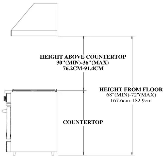
Site Preparation: Selecting the Appropriate Height for Installation
In selecting the proper height to mount the hood, take into consideration the stature of the person or persons who will be cooking. A minimum height of 30" off of the cooking surface to a maximum height of 36" will suit most users. It is recommended but not required that the hood be 6" wider than the cooking appliance to provide a proper capture area for heat and grease.
The bottom of the hood should be 30" minimum to 36" maximum above the countertop. This would typically result in the bottom of the hood being 66" – 72" above the floor. The bottom of the hood should never be more than 72" above the floor or more than 36" above the countertop. These dimensions provide safe and efficient operation of the hood.
INSTALLATION INSTRUCTIONS
Installation of Ducting for Proper Operation:
IMPORTANT
Proper installation of ducting is extremely important for optimal performance of your ventilation system. It is a basic requirement that the kitchen is provided with an air intake to ensure good air circulation and therefore proper operation of the hood. Without this incoming air a depression could form that would reduce the efficiency of the ventilation system. All CFMS are based on tests at 0.1 static pressure. Without static pressure all CFM's would be overstated.
- Consult with local codes for make-up air requirements
- Never reduce the duct size
- If ducts are combined the square inch area must reflect the total square inch area of the ducts being combined.
- Do not use flexible or corrugated duct. This type of duct will reflect airflow and reduce performance.
- Only use smooth, galvanized metal duct.
- Make the duct run as short and as straight as possible with as few turns as possible.
- Avoid sharp-angled turns. Use smooth gradual turns such as adjustable elbows or 45 degree angled turns.
- For duct runs over 20 feet increase the duct diameter by one inch for every ten feet of duct.
- Airflow must not be restricted at the end of the duct run.
- Damper is not provided. This must be included in duct run to prevent back drafts.
- Do not terminate venting into an attic or chimney.
Electrical Specifications:
IMPORTANT
This hood is designed to be plugged into a 3-prong ANSI or Non-GFCI outlet – 120Volt, 10amp. Ensure the outlet is not obstructed by the duct run prior to installation.
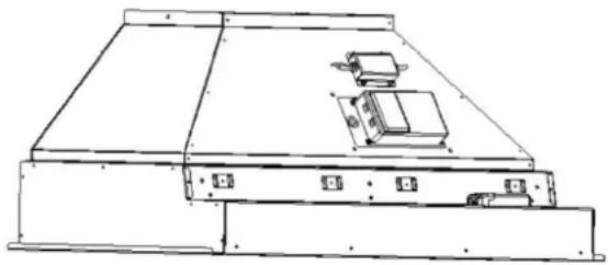
To connect power to in-hood blowers insert molex connector(s) into the opening located on the side of blower motor.
natural_image
Technical line drawing of a mechanical device with mounting base and internal components (no text or symbols)Ventilation Hood Mounting Instructions:
Step 1: Read all instructions thoroughly before beginning installation. If a duct cover is being used please proceed to page 13. For instructions on installing Manhattan style wall hoods proceed to page 15.
INSTALLATION INSTRUCTIONS
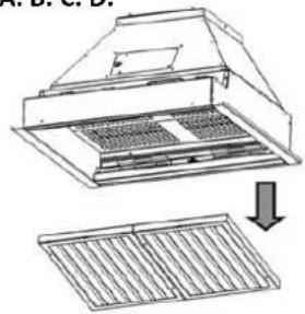
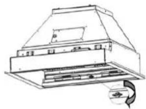
Step 2: Remove ventilation hood liner from outer shell. (Figures A through F)
A. B. C. D.
natural_image
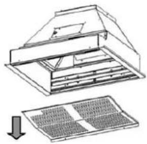
Diagram of a ventilation system with airflow and ventilation grilles (no text or labels)Figure A:
Remove Baffle Filters
Pull filters towards you to disengage from liner.
natural_image
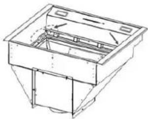
Technical line drawing of a kitchen air duct with ventilation slots and a circular component (no text or symbols)Figure B:
Remove Grease Trough
Turn fastening screw(s) 14 turn to unlock.
natural_image
Technical diagram of a roof structure with an arrow indicating downward motion (no text or symbols present)Figure C:
Remove Inner Shield
Remove screws (front and back) attaching shield to ventilation hood liner.
(Inner shield not on all models)
natural_image
Technical line drawing of a mechanical housing or enclosure with internal components and mounting holes (no text or symbols)Figure D:
Remove Control Panel
Remove screws (front and back) attaching panel to ventilation hood liner.
E. F.
natural_image
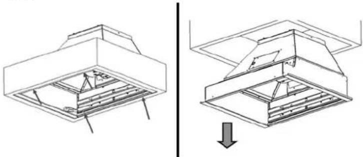
Technical line drawing of a structural frame with internal supports and a downward arrow indicating a detail (no text or symbols present)Figure E: Remove Mounting Screws
Remove screws in front and back of liner that attach it to the outer shell
Figure F: Remove Liner from Shell
Carefully slide liner out of outer shell.
Remove all protective film from exterior of liner and baffle filters. To completely remove the film from the filters the knobs will need to be removed by turning them counter-clockwise.
Step 3: Mount Outer Shell to Wall
- The bottom of the hood should be 30" minimum to 36" maximum above the countertop for efficient operation.
- This hood is designed to be plugged into a 3-prong Non-GFCI outlet - 120Volt, 10 amp. Ensure the outlet is not obstructed by the duct run prior to installation.
- If a duct cover is being used proceed to page 13 to determine which installation process will work best for your application. If no duct cover is being used proceed to Step 4.
- Anchor hood to wall with appropriate shear strength for weight of hood being installed (hardware not included). A number of holes are provided on the back of the shell but they do not need to be used. Additional holes can be drilled if needed to assist in mounting.
INSTALLATION INSTRUCTIONS
Step 4-1: Installing In-hood 600 CFM Blowers
natural_image
Technical line drawing of a kitchen range hood with air ducts and directional arrows (no text or symbols)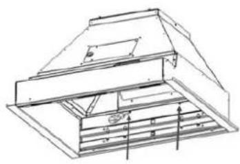
natural_image
Technical line drawing of a roof structure with support beams and ventilation grilles (no text or symbols)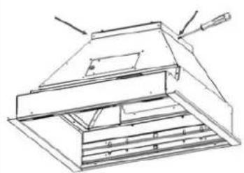
natural_image
Technical line drawing of a mechanical device with no visible text or symbols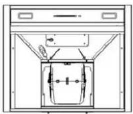
natural_image
Technical line drawing of a mechanical component or enclosure with no visible text or symbolsFigure A:
Attach Blower
Unscrew blower plate and set to top or rear discharge. Screw blower to plate with included hardware
Figure B:
Connect Plate Internally
Re-install all mounting screws inside of liner.
Figure C:
Connect Plate Externally
Re-install all mounting screws outside of liner.
Figure D:
Connect Power Supply
Connect molex connector from control box to blower.
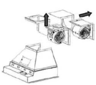
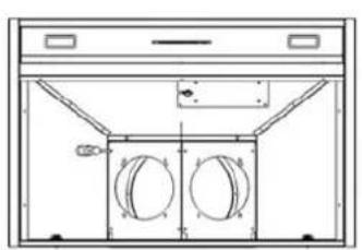
Step 4-2: Installing In-hood 1200 CFM Blowers
natural_image
Technical line drawing of a front view of an air duct system with two circular components (no text or symbols)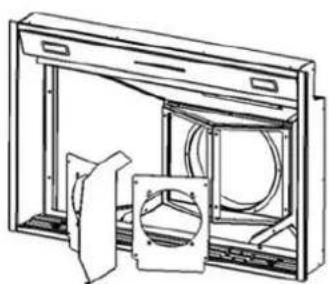
natural_image
Technical line drawing of a mechanical assembly with no visible text or symbols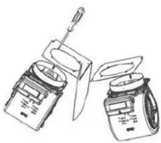
natural_image
Line drawing of two electronic devices with a screwdriver inserted, showing internal components (no text or symbols)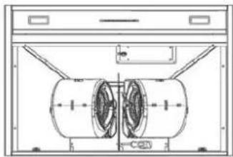
natural_image
Technical line drawing of a mechanical component with two cylindrical parts and mounting brackets (no text or symbols)Figure A:
Attach Blower Plate
Unscrew blower plate and set to top or rear discharge.
Figure B:
Connect Inner Plate
Screw inner plate with air divider onto base plate.
Figure C:
Connect Blowers
Install dual 600 CFM blowers onto hood with included hardware. Connect molex connectors to blowers.
Figure D:
Install Blowers in Hood
Screw each blower to the plate within the liner with hardware provided.
INSTALLATION INSTRUCTIONS
Step 4-3. Installing Remote Blowers
MODEL NUMBER: HYEX-1.0/HY-EX-1.4
MAXIMUM CFM: 1000 CFM/1400 CFM
VOLTS/HERTZ/AMPS: 115VAC, 60 Hz, 2.9A (HYEX-1.0) and 3.3A (HYEX-1.4)
REQUIRED DUCT SIZE: HYEX-1.0: 8" Round (51 sq. in. equiv.) / HYEX-1.4: 10" Round (80 sq. in. equiv.)
FLAT OR LOW SLOPE ROOF
- For flat roofs or roofs having pitch less than 1 12 " rise in 12", mount blower on roof curb. See Figure 1
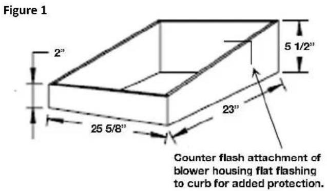
- Install the blower with discharge pointing down slope and away from prevailing winds.
- Use flashing and roofing mastic to seal the unit to prevent leaks.
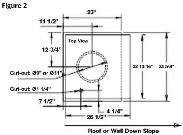
- Cut holes for ducting and electrical wiring as shown in Figure 2.
IMPORTANT: Remove foam block from inside housing before operating
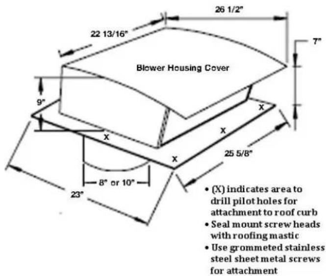
TYPICAL ROOF MOUNT
- Center the duct cutout between roof rafters
- Install the blower so its discharge is down slope and away from prevailing winds. According to the Standard Roofing Procedures: Shingles must cover rear flashing flange and a minimum of 12" of the side flanges. The flashing on the discharge side of the blower must rest on top of the shingles.
- The blower must be sealed between the roof and its underside with quality roofing mastic.
INSTALLATION INSTRUCTIONS
Step 4-3. Installing Remote Blowers
ELECTRICAL CONNECTIONS
WARNING: TURN OFF POWER AT THE SERVICE BOX PRIOR TO WIRING BLOWER
- Power supply for the blower s 115V AC, 60 Hz. See page 2 for specifications
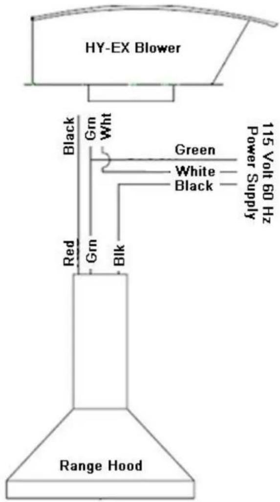
- Run electrical cable between the blower and the range hood or blower and wall switch. See Figure 3
- Remove top enclosure of the blower for access to the wiring terminal block.
- Push the electrical cable up through the bottom knock out of the blower body. Pull enough wire up into the housing to make attachment to the terminal block.
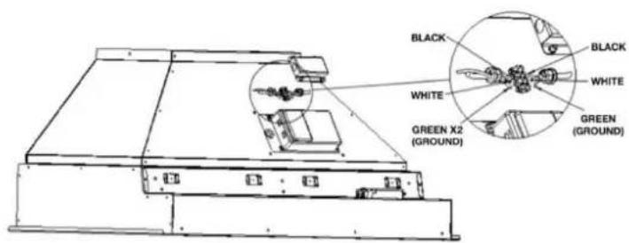
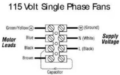
- Connect white, black and green wire to three terminal block on hood.
DUCT CONNECTIONS
- Use only round metal duct, elbows and transitions; or rectangular ducting having equivalent area of square inches as per required duct size.
- Tape or use joint sealant on all joints.
- Turn on power and check blower operation.
- Make sure damper opens and closes freely.
Figure 3
INSTALLATION INSTRUCTIONS
Step 4-4. Installing In-line Blowers
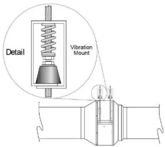
Mounting Option 1:
Please follow all applicable codes when installing this unit
-
Equipment should be hung at its proper elevation by using temporary fixtures that can be removed after vibration hangers are installed.
-
Hanger may be fastened directly to the structure or somewhere between suspended unit (be sure not to over tighten the neoprene element.
-
Install hangers.
-
Turn nuts on rod assembly clockwise one complete turn on each hanger. Repeat this procedure until temporary hanging fixtures are loose and load of piping or equipment is suspended completely on the vibration hangers.
-
Remove temporary hanger fixtures and level piping or equipment by taking additional turns on the spring/top hanger rod nut – clockwise to raise, counterclockwise to lower as required.
-
If equipping fan with isolators, they should be attached at this time.
-
See wiring section to complete installation.
Mounting Option 2:
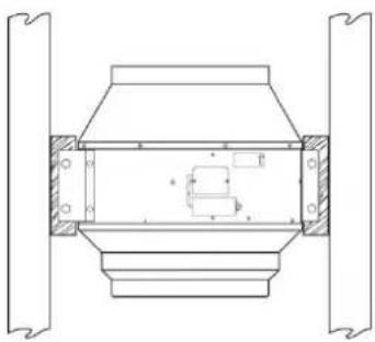
Please follow all applicable codes when installing this unit.
-
Install wood supports to structure for fan mounting.
-
If equipping with vibration mounts, attach to supports.
-
Attach fan to vibration mounts (be sure not to overtighten the neoprene element).
-
If equipping fan with isolators, they should be attached at this time.
-
See wiring section to complete installation.
natural_image
Technical line drawing of a mechanical component with flanged ends and internal cavity (no text or symbols)Mounting Option 3:
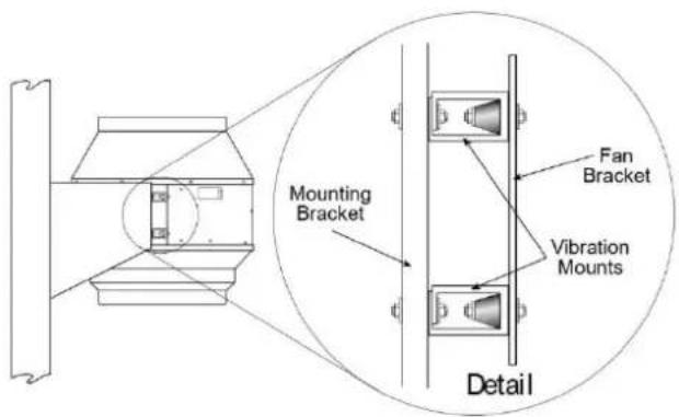
Please follow all applicable codes when installing this unit.
-
Create/install angle wood supports to structure for fan mounting.
-
If equipping with vibration mounts, attach to supports.
-
Attach fan to vibration mounts (be sure not to overtighten the neoprene element).
-
If equipping fan with isolators, they should be attached at this time.
-
See wiring section to complete installation.
INSTALLATION INSTRUCTIONS
Step 4-4. Installing In-line Blowers
Dimensions and Wiring:
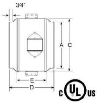
| Model A C | D E Weight | ||||
| ATEX-0.8 8 | 12 12 15 12 | 7 19 lbs | |||
| ATEX-1.2 10 | 14 15 8 21 | 1 lbs |
Step 5. Mount Outer Shell to Wall
- The bottom of the hood should be 30" minimum to 36" maximum above the countertop for efficient operation.
- This hood is designed to be plugged into a 3-prong Non-GFCI outlet – 120Volt, 10 amp. Ensure the outlet is not obstructed by the duct run prior to installation.
- If duct cover is being used mount duct cover mounting brackets to top of hood through holes provided. If no duct cover is being used proceed to Step 5.
- Anchor hood to wall with appropriate shear strength for weight of hood being installed (hardware not included). A number of holes are provided on the back of the shell but they do not need to be used. Additional holes can be drilled if needed to assist in mounting.
- If duct cover is being used anchor bracket to wall or ceiling (top) and wall (bottom). Do not install duct cover at this time.
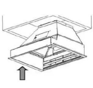
Step 6. Re-install Liner into Outer Shell
natural_image
Technical line drawing of a structural support frame with an upward arrow indicating direction (no text or symbols)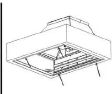
natural_image
Technical line drawing of a structural frame or enclosure with internal components and supports (no text or symbols)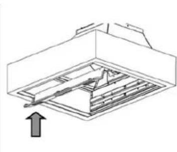
natural_image
Technical line drawing of a mechanical assembly with an upward arrow indicating motion (no text or symbols)Figure A: Lift Liner into Shell
Carefully re-install liner to avoid scratches or damage.
Figure B: Attach Liner to Shell
Re-install with hardware that mounted liner to shell during shipment.
Figure C: Re-install Control Panel
screws (front and back) attaching panel to ventilation hood liner.
Step 7. Connect Ducting to Ventilation Hood
Install ducting around starter collar on top or rear of hood and seal according to building code regulations.
INSTALLATION INSTRUCTIONS: 1-PIECE DUCT COVERS
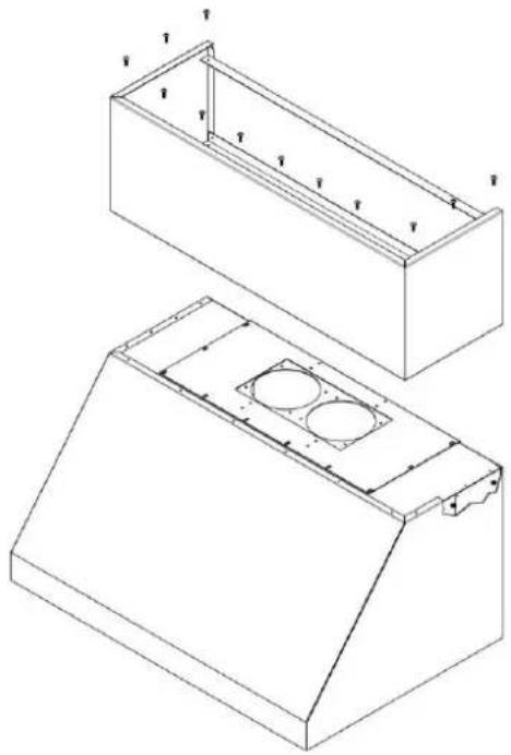
Step 8-1. Installing 1-Piece Duct Cover Option 1
- Secure duct cover to top of hood using machine screws provided.
- Mount complete unit to wall using instructions in Step 4 for Mounting Outer Shell to Wall.
- Install blower plate into hood sealing connection with duct work.
- Install blowers into hood.
natural_image
Technical line drawing of two views of a rectangular enclosure or housing with internal compartments and mounting holes (no text or symbols)Step 8-2. Installing 1-Piece Duct Cover Option 2
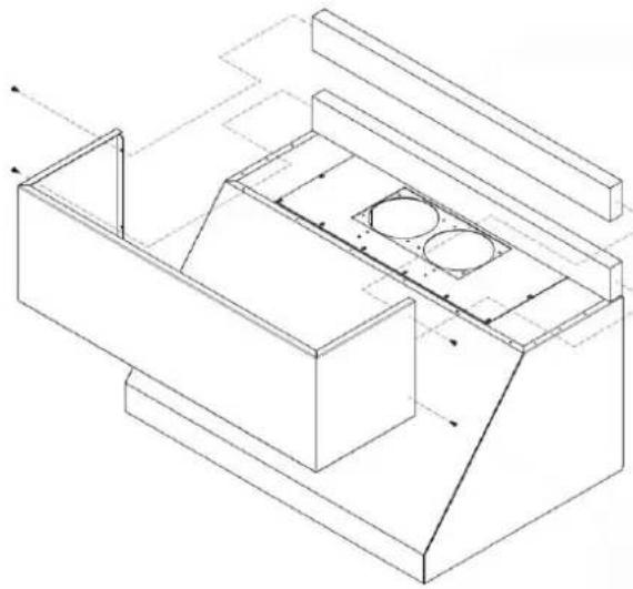
- Mount unit to wall using instructions in Step 4 for Mounting Outer Shell to Wall
- Secure wood blocks (not provided) on wall surface above hood.
- Position duct cover around blocks and secure with screws on the top and bottom of each side.
- Install blower plate into hood sealing connection with duct work.
- Install blowers into hood.
natural_image
Isometric line drawing of a mechanical housing or enclosure with internal compartments and mounting brackets (no text or symbols)INSTALLATION INSTRUCTIONS: TELESCOPIC DUCT COVERS
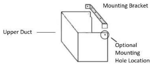
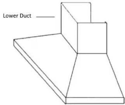
Step 8.3 Installing Telescopic Duct Cover Option 1
- Attach mounting bracket to wall 1/8" from ceiling and centered with hood.
- Attach lower portion of duct cover to hood with hardware provided.
- Slide upper portion into lower portion of duct cover.
- Anchor and level hood assembly to wall at desired mounting height.
- Install liner into shell following instructions in Step 6 on page 12.
- Slide starter collar into ducting on top or rear of hood and seal according to building code regulations.
- Slide upper portion of duct into mounting bracket and click into place.
(Duct cover should sit flush to ceiling, but gap could occur if wall and ceiling are not square)
Optional: Install screw through side of upper portion into mounting bracket on both sides. Hole to be provided by others. **For painted units damage could occur to painted surface from drilling**
Step 8-4. Installing Telescopic Duct Cover Option 2
- Attach mounting bracket to wall 1/8" from ceiling and centered with hood.
- Attach lower portion of duct cover to hood with hardware provided.
- Slide upper portion onto bracket and click into place.
(Duct cover should sit flush to ceiling, but gap could occur if wall and ceiling are not square)
- Slide hood shell and attached lower portion over upper portion and anchor to wall.
Optional: Install screw through side of upper portion into mounting bracket on both sides. Hole to be provided by others. **For painted units damage could occur to painted surface from drilling**
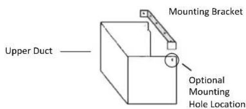
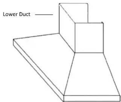
INSTALLATION INSTRUCTIONS
Manhattan Style Wall Hoods
- Follow Step 2 of installation instructions on removing liner from outer shell.
- Mount duct to ceiling using method below that best applies to your application.
- Mount blower(s) into duct cover using hardware provided.
- Anchor outer shell to wall and level.
-
Secure outer shell to duct cover using method below that best applies to your application.
-
Connect molex connectors for blower power and re-install liner using Step 5 from installation instructions.
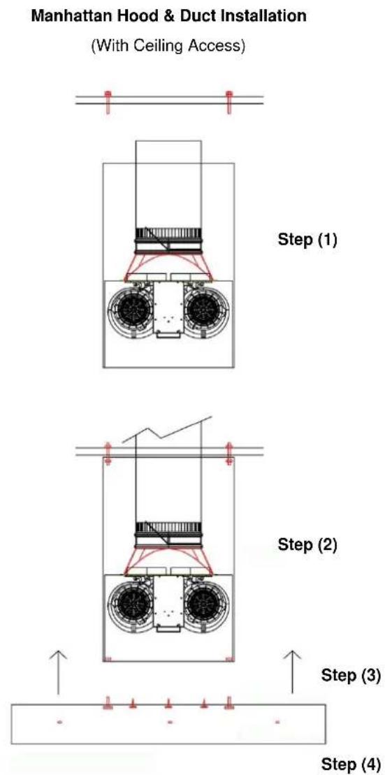
- Install duct work on duct cover.
- Install duct cover.
- Attach hood on duct cover.
- Anchor hood to wall
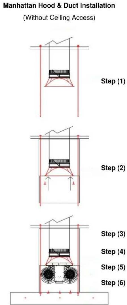
- Run all-thread, duct work and transition.
- Put duct cover in position and screw on transition.
- Install blower.
- Install hood.
- Attach hood on duct cover.
- Anchor hood to wall.
USE & CARE INSTRUCTIONS
Section 1: Control Panel
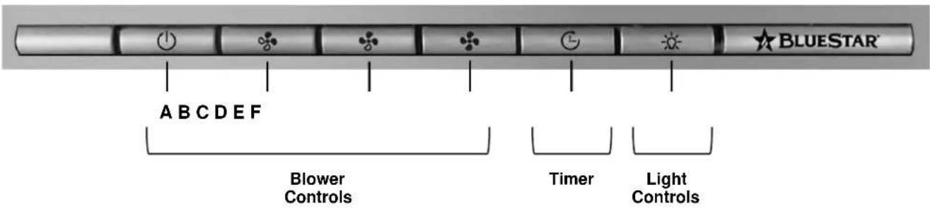
Blower Controls:
A – Blower starts on ^st 1 speed
B - 2 speed
C - r3 speed
D - ^14 speed (Boost Function) ^*
After 7 minutes of operation in Boost Mode the blower will automatically move to 3^rd speed.
Additional Controls:
E - Timer
Pressing button during operation will cause blower to run for 5 minutes at its current speed. Blower will automatically shut off.
F – Light On/Off plus Dimming Feature
Press once to turn light on and off. Hold in button to adjust light intensity. Selected intensity will stay in controller memory until changed.
Section 2: LED Lighting
Operation:
Press once to turn light on and off. Hold in button to adjust light intensity. Selected intensity will stay in controller memory until changed.
Replacing LED Lights:
LED lights are removable without uninstalling ventilation hood liner.
- Remove hood liner control panel by removing screws attaching it to hood.
- Access LED connections by unscrewing and removing the LED housing support.
- Push tabs to remove lights from control panel.
Specifications:
- Dimmable LED 3000K
- Adjustable light intensity with sweep and fade away function
• Light memory (Intensity stays at last position)
• Light beam angle 60°
- Lens material PC
- 12V DC
- Lumen 125
• PW Consumption: 1.3 watt
USE & CARE INSTRUCTIONS
Section 3: Baffle Filters
IMPORTANT
The function of the baffle filters is the absorption of grease particles that form during cooking. Do not operate ventilation hood without filters in hood. Baffle filters should be examined periodically to assure that the surfaces and parts are clean.
3.1: Removing Baffle Filters:
- Hold both handles located on the filter.
• Pull towards front of hood to depress spring system.
• Pull back of filter down and away from hood.
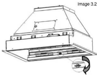
3.2: Removing Grease Trough:
Grease trough is located at base of baffle filters in rear of hood (see image 3.2).
- Turn fastening screw(s) 14 turn to unlock.
• Pull towards front of hood careful not to spill contents inside.
3.3: Removing Inner Shield:
Inner shield is located behind baffle filters (see image 3.3).
- Remove screws attaching shield to ventilation hood liner.
natural_image
Technical line drawing of a mechanical device with a labeled section (Image 3.2), showing internal components and a circular arrow indicating rotation or motion.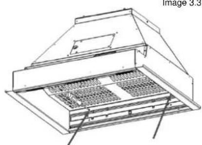
natural_image
Technical line drawing of a roof structure with ventilation grilles and ventilation duct (no text or symbols)Image 3.3

WARNING
3.4: Cleaning Baffle Filters
The baffle filters are dishwasher safe or can be cleaned in a sink with hot, soapy water. Do not use caustic detergent to clean the filters. Abrasive cleaners may harm or damage the finish. Do not disassemble the baffle filter. Disassembly will void the warranty.
Section 4: Cleaning Interior and Exterior

WARNING
Your hood must be kept clean and maintained properly
- Do not use abrasive cleaners, steel wool pads, abrasive cloths or cleaners with chlorides.
- Do not allow grease to accumulate. For best results wipe the canopy down with a soft cloth and hot, soapy water.
- The cleaning of the outside of the hood depends on the material used as a decorative exterior. See section for 4.2 for material specific cleaning instructions.
- Do not use abrasive or aggressive chemicals to clean the interior or exterior of the hood.

WARNING
Make sure that the electrical power is off before cleaning. The recommended detergent is a solution of water and a neutral liquid soap. It is very important for the liquid soap to not contain granules that could scratch the surface. First apply the solution to a soft cloth and then rub the cloth over the hood. It is important to follow the direction of the metal grain with the cloth. Do not pour any liquid directly on the ventilation hood. The cloth must have no buttons or fasteners that could scratch the surface. It is strictly forbidden to use chemical solvents, aggressive, grainy or abrasive products, alcohol or similar products that could damage the surface of the hood. The manufacturer will not be held responsible for functional or aesthetic damage caused by cleaning products which are not suitable or using inadequate cleaning methods.
4.1: Cleaning the Interior
Clean the interior of the hood with a cloth wetted in water and a neutral detergent or denatured alcohol as needed. Do not clean the electrical parts or blower with liquids or solvents.
4.2: Cleaning the Exterior
Exterior Finish: Brushed Stainless Steel
Clean the exterior of brushed stainless steel hoods using a soft cloth and quality stainless steel cleaner or warm soapy water. Follow all label instructions. Do not polish across the grain or in circles.
Exterior Finish: Paint with Gloss Finish
Clean the exterior of hood painted with a gloss finish using a soft cloth and quality glass cleaner or warm soapy water. Follow all label instructions. Do not polish across the grain or in circles.
Exterior Finish: Designer Metal (Brushed Brass & Copper, Antique Brass & Copper, Pewter & Oil Rubbed Bronze)
The following Designer Metals are treated with a protective clear coat that will prevent them from aging or discoloring over time. This clear coat will last the life of the hood unless removed by the homeowner. Clean with a microfiber cloth using Endust, Pledge or similar cleaner. Harsh cleaners such as Brite Boy will remove the clear coat and the metals will start to age.
Exterior Finish: Designer Metal (Polished Brass and Polished Copper)
The following Designer Metals are not treated with a protective coating due to a "rainbow" effect it causes on the metal. These finishes will patina over time without care and need occasional cleaning. Clean with a microfiber cloth using Endust, Pledge or similar cleaner for regular cleaning. For tough blemishes Brite Boy can be used with a microfiber cloth, but due to this product being slightly abrasive this should only be used in select situations.
- BLUESTAR®
- Unleash Your Inner Chef®
- Table of Contents
- INSTALLATION INSTRUCTIONS:
- USE AND CARE INSTRUCTIONS:
- IMPORTANT
- WARNING
- To reduce the risk of fire, electric shock or injury to persons observe the following:
- To reduce the risk of cooking appliance grease fire:
- Handling and Unpacking
- Handling:
- Unpacking:
- CAUTION
- Site Preparation: Selecting the Appropriate Height for Installation
- INSTALLATION INSTRUCTIONS
- Installation of Ducting for Proper Operation:
- Electrical Specifications:
- Ventilation Hood Mounting Instructions:
- Step 3: Mount Outer Shell to Wall
- FLAT OR LOW SLOPE ROOF
- TYPICAL ROOF MOUNT
- Step 4-3. Installing Remote Blowers
- ELECTRICAL CONNECTIONS
- WARNING: TURN OFF POWER AT THE SERVICE BOX PRIOR TO WIRING BLOWER
- DUCT CONNECTIONS
- Step 4-4. Installing In-line Blowers
- Mounting Option 1:
- Mounting Option 2:
- Mounting Option 3:
- Dimensions and Wiring:
- Step 5. Mount Outer Shell to Wall
- Step 6. Re-install Liner into Outer Shell
- Step 7. Connect Ducting to Ventilation Hood
- INSTALLATION INSTRUCTIONS: 1-PIECE DUCT COVERS
- Step 8-1. Installing 1-Piece Duct Cover Option 1
- Step 8-2. Installing 1-Piece Duct Cover Option 2
- INSTALLATION INSTRUCTIONS: TELESCOPIC DUCT COVERS
- Step 8.3 Installing Telescopic Duct Cover Option 1
- Step 8-4. Installing Telescopic Duct Cover Option 2
- Manhattan Style Wall Hoods
- USE & CARE INSTRUCTIONS
- Section 1: Control Panel
- Blower Controls:
- Additional Controls:
- E - Timer
- F – Light On/Off plus Dimming Feature
- Section 2: LED Lighting
- Operation:
- Replacing LED Lights:
- Specifications:
- Section 3: Baffle Filters
- 3.1: Removing Baffle Filters:
- 3.2: Removing Grease Trough:
- 3.3: Removing Inner Shield:
- 3.4: Cleaning Baffle Filters
- Section 4: Cleaning Interior and Exterior
- Your hood must be kept clean and maintained properly
- 4.1: Cleaning the Interior
- 4.2: Cleaning the Exterior
- Exterior Finish: Brushed Stainless Steel
- Exterior Finish: Paint with Gloss Finish
- Exterior Finish: Designer Metal (Brushed Brass & Copper, Antique Brass & Copper, Pewter & Oil Rubbed Bronze)
- Exterior Finish: Designer Metal (Polished Brass and Polished Copper)
Brand : BlueStar
Model : SCO48MLPLT
Category : Range hood