STA-10 - Subwoofer PowerBass - Free user manual and instructions
Find the device manual for free STA-10 PowerBass in PDF.


| Product Type | Amplified Bass System |
| Speaker Size | 10 inches |
| Impedance | 2 ohms |
| Frequency Response | 20 Hz - 200 Hz |
| Sensitivity | 95 dB (1W/1M) |
| Magnet Size | 30 oz |
| Voice Coil Diameter | 1.5 inches |
| Amplifier Power (RMS) | 200 watts |
| Amplifier Power (Peak) | 400 watts |
| Amplifier Class | Class D monaural |
| Enclosure Material | Die-cast aluminum |
| Cone Material | Aluminum-coated polypropylene |
| Voice Coil Type | Kapton high temperature |
| Fuse Rating | 30A ATC type |
| Low Level Input Sensitivity | 250 mV - 10 V (switchable) |
| High Level Input Sensitivity | 1.0 V - 10 V |
| Auto Turn-On | Yes (with high level input) |
| Phase Switch | 0° / 180° |
| Bass EQ Boost | 0 - 12 dB at 45 Hz |
| Low Pass Filter Range | 40 Hz - 200 Hz |
| Sub Sonic Filter Range | 20 Hz - 50 Hz |
| Remote Level Control | Yes (wired RJ45) |
| Power Supply | 12V DC negative ground |
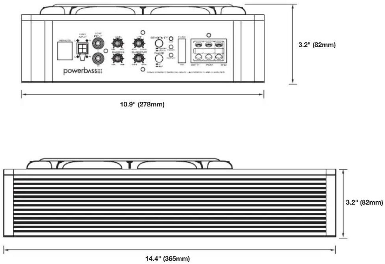
| Dimensions (W x H x D) | 14.4 x 10.9 x 3.2 inches (365 x 278 x 82 mm) |
Frequently Asked Questions - STA-10 PowerBass
User questions about STA-10 PowerBass
0 question about this device. Answer the ones you know or ask your own.
Ask a new question about this device
Download the instructions for your Subwoofer in PDF format for free! Find your manual STA-10 - PowerBass and take your electronic device back in hand. On this page are published all the documents necessary for the use of your device. STA-10 by PowerBass.
USER MANUAL STA-10 PowerBass
powerbass® AutoSound

natural_image
Black powerbase electronic device with ventilation grille and external ports (no visible text or symbols on body)STA-10
AMPLIFIED BASS SYSTEM
Owners Manual
Please read through this manual to familiarize yourself with your new amplifier. Should your PowerBass Autosound speaker system ever require service, you will need to have the original dated receipt.
powerbass® AutoSound
Thank you and Congratulations
Congratulations on your purchase of a PowerBass Autosound speaker system. You now own a speaker of uncompromising design and engineering from a factory that truly believes in the relentless pursuit of perfection. Incorporating the highest quality parts and state-of-the-art materials, these speakers display the ultimate balance between high fidelity, performance and long-lasting reliability.

At PowerBass USA, Inc. we are confident you will have many years of outstanding enjoyment from this great SPEAKER investment. For maximum performance we recommend that you have your new PowerBass Autosound product installed by an Authorized PowerBass Autosound Dealer.
To learn more about PowerBass, please visit us on the World Wide Web at
http://www.powerbassusa.com
Δ Warning Δ
Continuous exposure to sound pressure levels in excess of 100 dB can cause permanent hearing loss. PowerBass Autosound Speakers are capable of producing sound pressure levels well over 170 dB. Please observe all local sound ordinances while listening to your PowerBass Autosound system. PowerBass USA, Inc. accepts no liability for hearing loss, bodily injury, or property damage due to the result of use or misuse of this product.
POWERBASS AMPLIFIED BASS SYSTEM FEATURES
BUILT-IN HIGH POWERED AMPLIFIER: Contains a high power Class D monaural amplifier complete with chassis mounted adjustable Gain, Low Pass Filter and Bass Eq controls for sonic integration into most existing factory or aftermarket car stereo systems and engineered perfectly to power the subwoofer.
SELECTABLE SENSITIVITY SETTING: With this button pressed in, the preamp sensitivity will accept input voltages from 2V-10V. This will be used if High Level Inputs are connected to your amplified enclosure. With this button left out, the preamp sensitivity will now accept 250mV-6V. This will be used if Low Level / RCA Inputs are connected to your amplified enclosure.
DIE-CAST ALUMINUM ENCLOSURE DESIGN: This enclosure is constructed from aircraft grade aluminum that has been acoustically tuned with the integrated custom tooled passive radiator for optimum bass output.
REMOTE SUBWOOFER LEVEL CONTROL: This wired remote functions as the amplifier's secondary gain circuit and can be adjusted from the driver's seat. The remote will not increase the output beyond the GAIN setting on the amplifier. Supplied with cable to reach your dash even when the bass enclosure is mounted under the seat.
ALUMINUM-COATED POLYPROPYLENE CONE: A thermoplastic polymer cone was selected to help resist moisture and other elements while the rubber surround offers more excursion as well as protection against deterioration than other materials.
KSV HIGH TEMPERATURE VOICE COIL: These specially designed resin coated high temperature Kapton® voice coils measure 1 1/2 inches in diameter to ensure high power handling and precise linear excursion while maximizing thermal heat dissipation.
AUTO TURN-ON CIRCUIT: When using the high level inputs, the amplifier will turn on automatically when it senses a signal from your radio.
Kapton® is a registered trademark of E.I. du Pont de Nemours and Company
SPECIFICATIONS FOR STA-10 SUBWOOFER SYSTEM
(Due to Constant Improvements, Specifications and Parameters are subject to change without notice.)
| Size System | Impedance | Frequency Response | Sensitivity 1W/1M | Magnet Size | Voice Coil Dia. | Low Level Input Sensitivity | High Level Input Sensitivity | Amp Power RMS/Peak |
| Single 10" | 2-ohm | 20Hz-200Hz | 95dB | 30 oz. | 1.5" | 250mV - 10V | 1.0V - 10V | 200W/400W |
UNPACKING THE ENCLOSURE
Every attempt has been made to transport your new PowerBass STA subwoofer system safely. Carefully unpack the enclosure and inspect it thoroughly for any damage that may have occurred during shipping. Notify your local PowerBass dealer immediately should you notice any damage prior to installing the unit. Be sure to keep the carton and packing material until your system is operational. The original boxes will do the best job of protecting your speaker system if they need to be transported.
INSTALLATION EXPERIENCE
Installation of PowerBass Autosound Speakers requires experience with a variety of mechanical and electrical procedures. This manual only provides general installation and operating instructions. If you have any reservations about your installation skills or lack the proper tools, please contact your local PowerBass Autosound dealer for assistance.
IMPORTANT: This amplified subwoofer system is designed for operation in vehicles with 12-volt Negative ground electrical systems only.
ENCLOSURE PLACEMENT TIPS & RECOMMENDATIONS
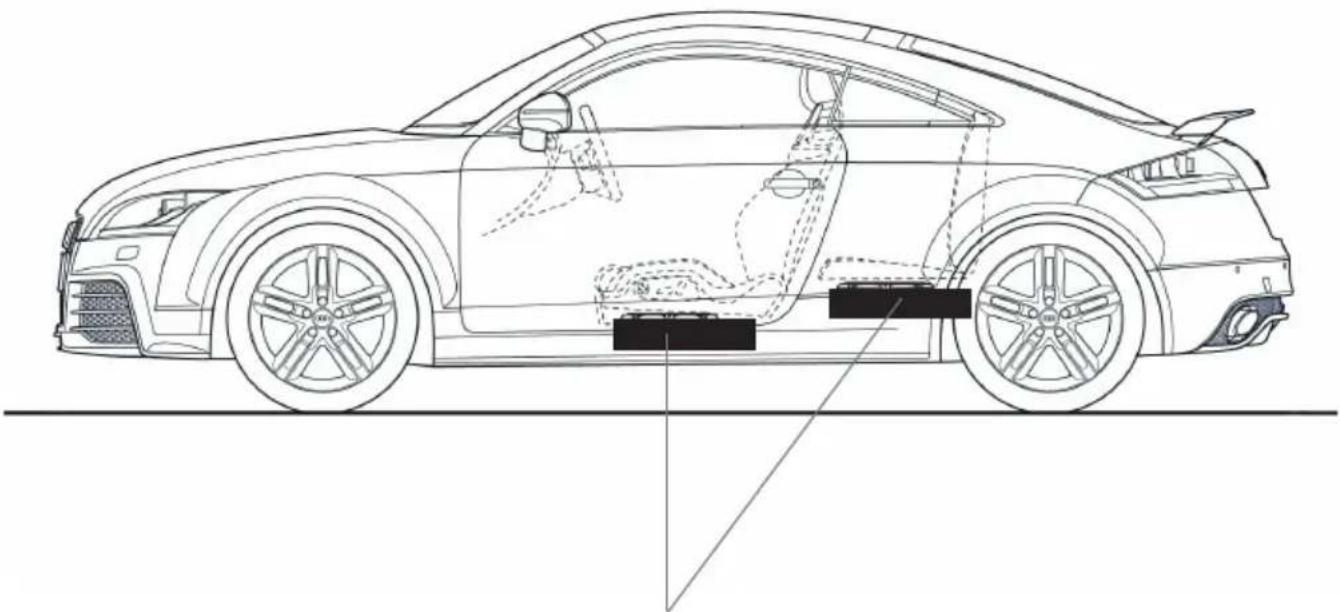
Your Powerbass Amplified Bass system must be properly placed in the vehicle for optimum performance. Find a spot under your seats where the enclosure will not get in the way of any moving parts of the seat. Make sure that the seat moves freely if it is adjustable.
Ideally there should be enough room around the enclosure which is also a heatsink for the amplifier so it can remain cool.
WARNING: Make sure where ever you choose to place the enclosure it's a dry location on a solid surface. Take care that none of the mounting screws will pierce any wiring harnesses, brake or fuel lines, the vehicles fuel tank, spare tire or any other parts of the vehicle. Some or all of these may be located behind or under the mounting surface.
natural_image
Side-view technical line drawing of a car showing internal components and structural layout (no text or labels)Fig.1 Possible locations for installation
ENCLOSURE DIMENSIONS AND SPECIFICATIONS
NOTE: The speaker system must be secured to protect the enclosure from moving. Before final mounting, be sure to check the sound one last time and make sure the enclosure is properly placed to produce the desired bass output. Use the four mounting 20mm screws provided and secure them to the enclosure. Mounting holes located on the top of the unit.
STA-10 AMPLIFER CONTROL PANEL LAYOUT
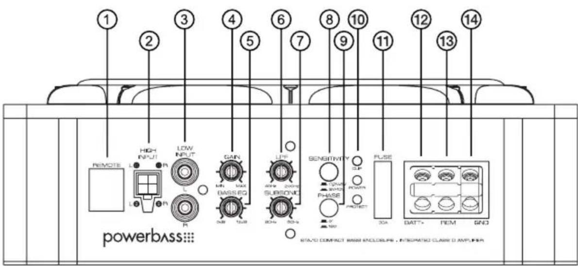
This is the connector port for the STA Remote Level control. Now the amplifiers secondary gain circuit can be adjusted from the driver's seat.
2. HIGH INPUT
Use the High Input 4-pin Molex style jack when connecting to the speaker leads directly from a factory radio without the use of a low level convertor. Be sure to observe the correct speaker polarity. (Do not use if you are using the LOW INPUT from the RCA jacks).
3. LOW INPUT (RCA) Jacks
These RCA style input jacks are for use with source units that have RCA line level inputs. A source unit with a minimum output of 250mV is required for proper operation. However, this input can accept levels up to 6Vrms.
4. GAIN Control
This control is used to match the sensitivity of the amplifier to the particular source unit (radio) that you are using up to 250mV - 10V. Please note the GAIN control is not a volume control, it is a level matching circuit.
5. BASS EQ Control
This equalization circuit is used to enhance the low frequency response of the vehicles interior. With up to 12dB of boost centered at 45Hz the Bass EQ can be adjusted to meet your personal taste. Please note that by boosting the Bass EQ to its full +12dB you are asking the amplifier to work 10 times harder!
6. LPF (Low Pass Filter) Control
This filter allows the low pass of frequency and has an adjustable crossover point from 40Hz to 200Hz. A setting of 40Hz will produce only the low frequencies (deep bass). A max setting of 200Hz will allow the amplifier to produce a more punchy (higher) bass response.
7. SUB SONIC Control
This control is continuously adjustable from 20Hz-50Hz at 12dB per octave to provide an extra level of speaker protection from bass robbing power at unheard frequencies
8. SENSITIVITY
A wide range of signal input voltages can be accommodated by the STA-10 with the push of a button (250mV - 10V). This wide range is split up into two sub-ranges, accessible by pushing the sensitivity switch: IN 2V-10V; OUT 0.2V - 6V
9. PHASE Switch
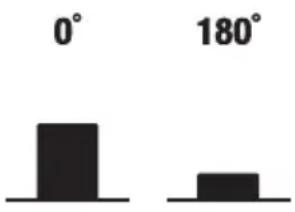
This switch will reverse the phase of the speaker output without having to touch any wiring. 0 is normal. 180 reverses the output. Select whichever setting provides the most bass in your application.
10. POWER Indicator
The top BLUE L.E.D. lights up when the power is on and the system is wired correctly. The bottom RED L.E.D. lights up when the unit is in protection.
11. FUSE
For convenience most PowerBass AutoSound amplifiers utilize common automotive ATC type fuses. For continued protection in the event that a fuse blows, replace the fuse only with the same value. STA-10 uses a 30A fuse. CAUTION: These power fuses on the amplifier chassis are for protecting the amp against over current situation. To protect the vehicles electrical system, an additional fuse should be used within 18-inches of the battery on the 12V+ cable.
12. BATT+ (12 Volt Positive)
This terminal is the main power input for the amplifier and must be connected directly to the positive (+) terminal of the battery. A minimum of 8ga cable is required.
13. REM (Remote)
The amplifier in your STA enclosure can be turned on by applying 12 volts to this terminal. This can be on the rear of the source unit (radio) in the form of an output or remote output. If this is not available you can wire up to the ACC position on the ignition key switch. An 18ga wire is sufficient to run the remote. NOTE: If using the high input, the amplifier will turn on automatically when it senses a signal from your radio. You will not have to hook up the REM wire in this case
14. GND (Ground Input Connection)
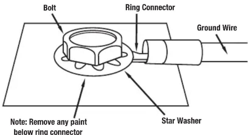
A good quality ground is required for the amplifier to operate a peak performance. A short length of cable the same gauge as your power cable (8ga is recommended) should be used to attach the ground terminal directly to the chassis of the vehicle. Make sure that all of the paint is sanded or scraped away to ensure a good quality ground connection.
POWER WIRING AND SIGNAL CONNECTIONS
POWER CONNECTION
BATT+ The amplifier should be wired directly to the vehicle battery using a 8ga power cable. Start at the vehicle battery and run the power cable through the vehicle's firewall using grommets to the amplifier's BATT + screw terminal. If factory grommets are not available install grommets yourself to protect the cable from sharp metal edges.
Avoid running the power cable over the engine components and near heater cores. The use of an in-line fuse or circuit breaker is a must, this will prevent the risk of potential fire caused by a short in the power cable. Connect the fuse holder or circuit breaker as close to the battery positive (+) terminal as possible (no farther than 18-inches from the battery).
The fuse or breaker amperage should be no greater than the fuse rating found on the amplifier control panel located on the side of the STA enclosure. You can now connect the cable to the battery, but remember to leave the fuse out or the circuit breaker "off" until the other cable connections are made. It is highly recommended that the cable end connecting to the amplifier is terminated with a spade or ring terminal.
IMPORTANT—You MUST install a fuse holder with an appropriate fuse in line with the power cable no further than 18-inches from the battery.
REM Run 18ga wire (not included) to the radio lead or remote output. This wire is responsible for turning the amplifier on and off. If the source unit (radio) is not equipped with a Remote lead you can connect this wire to an accessory or ignition point at the vehicle fuse block. In this type of installation, the amplifier will be on whenever the ignition is on.
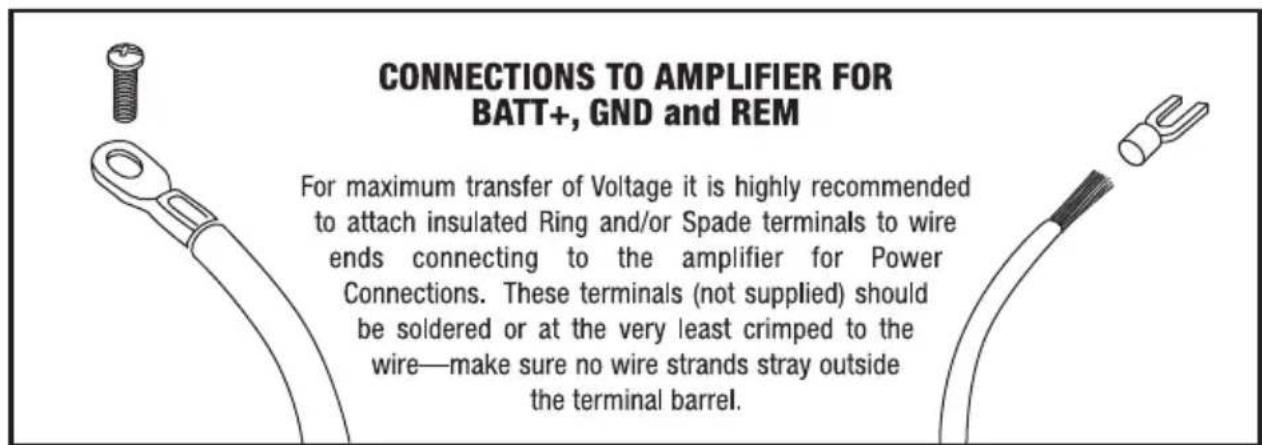
GND A cable of the same size (gauge) as the power cable should be used to ground the amplifier. Connect the ground wire from the screw terminal marked GND on the amplifier control panel to the nearest bare-metal surface on the vehicle. Keep the length of the ground cable to an absolute minimum using a spade terminal at the amplifier end and ring terminal as shown in below at the chassis end (Fig 3).
Fig.3
INPUT SIGNAL (CHOOSING THE HIGH OR LOW INPUTS)
The STA amplifier control panel input signal connects to the head unit's High Level (speaker wire) output OR Low Level (RCA) output—provided the radio is so equipped with Line Out. A dedicated subwoofer or low level signal will deliver the best performance. If unavailable use the high level inputs, as will be the case with most factory head units. (Note once you have chosen whether you will use the High Level or Low Level inputs follow the corresponding wiring diagrams on the following pages)
NOTE: Never use BOTH High and Low Level inputs at the same time. You must select one or the other!
High Level Input Connections (fig 4)
For radios with only speaker outputs (including most Factory source units). Using the 4-pin Molex style wiring harness provided, splice directly into the radio's speaker outputs. Do not break the connection with the source (radio) and the speakers. Be sure to maintain proper speaker polarity.
Wire Color Connect to
Gray
Gray w/ Black Stripe
White
White w/ Black Stripe
Left +
Left -
Right +
Right -
Another option is to tap off the existing front or rear full range speakers. Once again be sure to follow the correct polarity.
NOTE: If using the high input, the amplifier will turn on automatically when it senses a signal from your radio. You will not have to hook up the REM wire in this case.
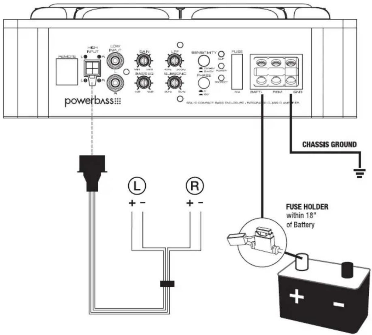
Fig.4 High Level Connections
NOTE: Use 8ga power/ground wire for BATT+ and GND connections.
Remote lead is not needed with a High Level connection but is strongly recommended.
Low Level Input and RCA Interconnect Wiring (fig 5)
For radios that have RCA line outputs. You will need to connect the low-level RCA style inputs from the STA to the line-outputs from the radio (source) via an RCA interconnect commonly called a “stereo patch cord”. Choose the correct length and style of RCA interconnects for your needs. Always use high quality RCA audio cables (not supplied) for signal connections—those with multiple layers of shielding or a twisted pair variety for better noise rejection.
Be extra careful when routing your RCA audio interconnect cables. Car environments are notorious for poorly insulated wires. This means that hiss, engine noise and fan noise can be easily picked up through RCA cables if run incorrectly. Take care to make sure the power and audio signal are not on the same side of the vehicle and they do not cross each other.
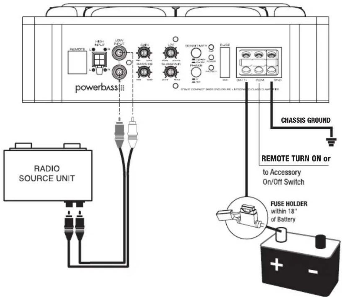
Fig.5 Low Level Connections
NOTE: Use 8ga power/ground wire for BATT+ and GND connections
SET UP ADJUSTMENTS
Your STA enclosure uses several controls to provide sonic integration with virtually any vehicles unique acoustic properties. Please read the following section carefully to familiarize yourself with the function of each control. The following adjustment sequence is recommended to properly tune your STA enclosure. By first adjusting the GAIN, the LPF, then the PHASE switch, followed by the BASS EQ (in this order) will give you the best results.
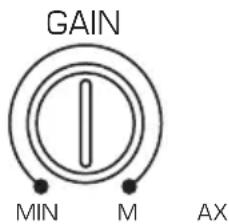
Fig.6 GAIN Control
Input GAIN Control
This control allows you to match the input level of the amplifier to the output level of your head unit (Fig 6). Matching the input can be accomplished in four simple steps:
- Make sure the remote gain control is not plugged in until after the master gain control is set.
- Set the GAIN control on the amplifier to MIN (completely counter clock wise).
- Turn on the head unit and adjust the volume to 2/3 maximum, and set the BASS and TREBLE on the radio (source) to zero or flat.
- Turn the GAIN control clockwise until the sound just begins to distort, then back off slightly to cut distortion and operate at optimum gain.
Remember, the GAIN control is not a volume control. Ignoring these four steps above may leave you with a damaged woofer and/or damaged amplifier.
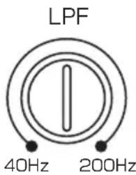
Fig.7 Low Pass Control (LPF)
LPF (Low Pass Filter) Crossover Adjustment
Since musical tastes vary, adjust the crossover by ear while listening to the music of your choice. Turn the crossover LPF adjustment all the way down to 40Hz. Then slowly turn the knob up until desired sound is achieved. Normal listening level should be right around 100Hz to 150Hz. Use common sense when adjusting the crossover. When properly adjusted, the bass from the STA enclosure should blend in with the rest of your speakers and not overpower the music. Be sure to set the tone controls of your radio (source unit) to flat while dialing in the crossover. (Fig 7)
bar
| Angle | Value | |---|---| | 0° | High | | 180° | Low |Fig.8 PHASE Switch
Setting the PHASE switch
Start with the PHASE switch set at 0^ and play a favorite music track that contains some solid bass (make sure the BASS EQ control is set at the 12 o'clock position). Then flip the switch to 180^ and listen to the same musical track again. Choose the setting that provides the best bass response according to your taste.

Fig.9 Bass EQ Control
BASS EQ Adjustment
This special feature is designed to provide you with more powerful sound quality and it allows you to increase the Bass up to +12dB. Keep in mind that more is not always better. Adjusting the control to the MAX (12dB) position will stress the amplifier and the woofer which could result in damage. (Fig 9)
NOTE: Although this adjustment sequence will in most cases provide the best tuning results, the actual process may include several readjustments of each of the controls since their settings interact with each other. If necessary, consult your Authorized PowerBass dealer for help tuning your system.
natural_image
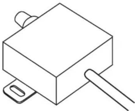
Simple line drawing of a rectangular electronic component with two protruding pins and a handle (no text or symbols)Fig.10 Remote Level Controller / PB-GAIN1
Remote Level Controller
Your PowerBass STA enclosure includes a wired Remote Level Subwoofer control module. To connect the Remote Subwoofer Gain control to the amplified enclosure, simply insert a RJ45 ethernet jack into the REMOTE gain port. Mount the module within easy reach or under your dash. (Fig 10)
NOTE: DO NOT plug in or disconnect the remote bass level controller when the amplifier is on!
Break In Period
To get the most from your woofer we recommend a "break-in" period of at least 40 hours (typically 2 weeks) at no more than 1/3 of maximum volume.
During this time the cone and spider assembly will gradually break in resulting in greater performance and more listening enjoyment.
TROUBLESHOOTING TIPS
| Problem Solution | |
| Power BLUE LED not ON | With a Volt OHM Meter (VOM) check:• +12 Volt power terminal (should read +12 to +16VDC• Remote turn-on terminal (should read +12 to +16VDC)• Ground Terminal |
| Power LED lights BLUE, no output | • Check RCA connections• Substitute known good Source Unit• Check for signal on the RCA cable with VOM in AC position |
| The RED LED is ON, no output and 1. Amp is VERY HOT2. Amp shuts down ONLY when the vehicle is running | • Thermal protection is engaged. Check for proper impedance at speaker terminals. Also check for adequate air flow around the amplifier.• Voltage protection engaged. Voltage to the amp is not within the 10-16 VDC operating range. Have the battery/charging system inspected. |
| RED Clip LED is ON | • Readjust your Gain or Bass EQ settings to where the Clip indicator flashes during heavy bass notes.• If the Clip indicator is constantly on this means the output of the amplifier is now distorted and needs to be readjusted. |
| Alternator noise (varies with RPM) | • Check for damaged RCA cable.• Check routing of RCA cable• Check Source Unit for good ground• Check amp gain setting, turn down if set too high |

Product Disposal – Certain international, national and/or local laws and/or regulations may apply regarding the disposal of this product. For further detailed information, please contact the retailer where you purchased this product or the PowerBass Importer/Distributor in your country.
WE WANT YOU LISTENING FOR A LIFETIME
Dear Customer,
Selecting fine audio equipment such as the speakers you've just purchased is only the start of your musical enjoyment. Now it's time to consider how you can maximize the fun and excitement your equipment offers. PowerBass and the Consumer Electronics Association (CEA) want you to get the most out of your equipment by playing at a safe level. One that lets the sound come through loud and clear without annoying, blaring or distortion- and, most importantly, without affecting your sensitive hearing.
Sound can be deceiving. Over time your hearing "comfort level" adapts to higher volumes of sound. So what sounds "normal" can actually be loud and harmful to your hearing. Guard against this by setting your equipment at a safe level BEFORE your hearing adapts.
PowerBass and the CEA want you to listening for a lifetime!

WARRANTY NOTES
Should a warranty issue arise with our amplified subwoofer system PowerBass will replace the defective woofer only. Do not send the entire enclosure, unless the enclosure or amplifier is defective itself. PowerBass does not warranty the cosmetics of the enclosure once installed in the vehicle.
POWERBASS AUTOSOUND LIMITED WARRANTY POLICY
PowerBass USA, Inc. offers limited warranty on PowerBass products under normal use on the following terms:
PowerBass Autosound Speakers are to be free of defects in material and workmanship for a period of one (1) year.
This warranty applies only to PowerBass products sold to consumers by Authorized PowerBass Dealers in the United States of America. Products purchased by consumers from a PowerBass dealer in another country are covered only by that country's Distributor and not by PowerBass USA.
This warranty covers only the original purchaser of PowerBass product. In order to receive service, the purchaser must provide PowerBass with the receipt stating the consumer name, dealer, product and date of purchase.
Products found to be defective during the warranty period will be repaired or replaced (with a product deemed to be equivalent) at PowerBass's discretion and will not be liable for incidental or consequential damages. PowerBass will not warranty this product under the following situations:
- Amplifiers received with apparent rust or corrosion
- Any evidence of liquid damage or exposure to excessive heat
- Abuse such as holes in the cone, surround or ripped spider
- Voice coil damage due to amplifier clipping or distortion
- Product that has not been installed according to this owners manual
Any implied warranties including warranties of fitness for use and merchantability are limited in duration to the period of the express warranty set forth above. Some states do not allow limitations on the length of an implied warranty, so this limitation may not apply. No person is authorized to assume for PowerBass any other liability in connection with the sale of this product.
Please call (909) 923-3868 for PowerBass Customer Service. You must obtain an RA# (Return Authorization Number) to return any product to PowerBass. The RA number must be prominently marked on the outside of the shipping carton or the delivery will be refused. Please pack your return carefully; we are not responsible for items damaged in shipping. Return the defective product along with a copy of the original dated retail sales receipt, plus \$12.00 for handling and diagnostic evaluation to:
PowerBass USA, Inc., Attn: Returns (RA#____)
2133 S. Green Privado, Ontario, CA 91761
Residents of HI, AK and US territories will be charged for return shipping. All inquires regarding service and warranty should be sent to the above address.

PowerBass Autosound – A division of PowerBass USA, Inc.
2133 S. Green Privado – Ontario, CA 91761
Tel. (909) 923-3868 - Fax (909) 923-8048
www.powerbassusa.com
- powerbass® AutoSound
- AMPLIFIED BASS SYSTEM
- Owners Manual
- Thank you and Congratulations
- Δ Warning Δ
- POWERBASS AMPLIFIED BASS SYSTEM FEATURES
- SPECIFICATIONS FOR STA-10 SUBWOOFER SYSTEM
- UNPACKING THE ENCLOSURE
- INSTALLATION EXPERIENCE
- ENCLOSURE PLACEMENT TIPS & RECOMMENDATIONS
- ENCLOSURE DIMENSIONS AND SPECIFICATIONS
- STA-10 AMPLIFER CONTROL PANEL LAYOUT
- HIGH INPUT
- LOW INPUT (RCA) Jacks
- GAIN Control
- BASS EQ Control
- LPF (Low Pass Filter) Control
- SUB SONIC Control
- SENSITIVITY
- PHASE Switch
- POWER Indicator
- FUSE
- BATT+ (12 Volt Positive)
- REM (Remote)
- GND (Ground Input Connection)
- POWER WIRING AND SIGNAL CONNECTIONS
- POWER CONNECTION
- IMPORTANT—You MUST install a fuse holder with an appropriate fuse in line with the power cable no further than 18-inches from the battery.
- INPUT SIGNAL (CHOOSING THE HIGH OR LOW INPUTS)
- High Level Input Connections (fig 4)
- Low Level Input and RCA Interconnect Wiring (fig 5)
- SET UP ADJUSTMENTS
- Input GAIN Control
- LPF (Low Pass Filter) Crossover Adjustment
- Setting the PHASE switch
- BASS EQ Adjustment
- Remote Level Controller
- Break In Period
- TROUBLESHOOTING TIPS
- WE WANT YOU LISTENING FOR A LIFETIME
- WARRANTY NOTES
- POWERBASS AUTOSOUND LIMITED WARRANTY POLICY
- PowerBass Autosound Speakers are to be free of defects in material and workmanship for a period of one (1) year.
Brand : PowerBass
Model : STA-10
Category : Subwoofer