
DuoFern 9485 - Thermostat RADEMACHER - Free user manual and instructions
Find the device manual for free DuoFern 9485 RADEMACHER in PDF.


| Product Type | Wireless Room Thermostat |
| Brand | Rademacher |
| Model | DuoFern 9485 |
| Wireless Protocol | DuoFern (868 MHz) |
| Power Supply | 2 x AA batteries (1.5V) |
| Battery Life | Approx. 2 years |
| Display | LCD with backlight |
| Temperature Setting Range | 5°C to 30°C |
| Measurement Accuracy | ±0.5°C |
| Programming | Weekly schedule with up to 6 time periods per day |
| Functions | Frost protection, window open detection, holiday mode, manual override |
| Installation | Wall-mounted (screws included) or freestanding |
| Dimensions (W x H x D) | 80 x 80 x 25 mm |
| Weight (without batteries) | 120 g |
| Protection Class | IP20 |
| Ambient Temperature | 0°C to 50°C |
| Warranty | 2 years |
| Included Accessories | Mounting plate, screws, dowels, user manual |
| Compatibility | DuoFern receivers (e.g., Rademacher actuators) |
| Maintenance | Replace batteries when low; clean with dry cloth |
| Repairability | Battery replacement only; no user-serviceable parts |
Frequently Asked Questions - DuoFern 9485 RADEMACHER
User questions about DuoFern 9485 RADEMACHER
0 question about this device. Answer the ones you know or ask your own.
Ask a new question about this device
Download the instructions for your Thermostat in PDF format for free! Find your manual DuoFern 9485 - RADEMACHER and take your electronic device back in hand. On this page are published all the documents necessary for the use of your device. DuoFern 9485 by RADEMACHER.
USER MANUAL DuoFern 9485 RADEMACHER
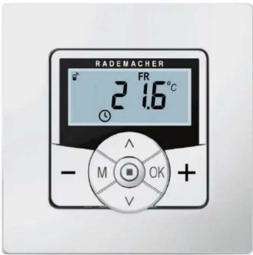
DuoFern Room Thermostat 2
Instruction manual for the electrical connection and for commissioning
Item no. 3250 18 72
Type: 9485-1
1. This manual....5
1.1 How to use this manual ....5
2. Hazard symbols ......6
2.1 Levels of danger and signal words....6
2.2 Symbols and depictions used....7
3. Safety instructions....8
3.1 Intended use....9
3.2 Improper use....10
3.3 Required expert knowledge of the installer....10
3.4 Glossary - definition 11
4. Included in delivery 13
5. General view of the operating unit......14
5.1 General view of the installation housing....16
5.2 Electrical connections.... 17
5.3 Display and its symbols.... 18
5.4 Views of the standard display 20
6. Product description 22
6.1 Overview of functions 25
6.2 Functions and sample applications....26
7. Technical specifications 34
7.1 Factory settings.... 37
7.2 Conduct in the event of a power failure 38
8. Safety instructions for the electrical connection ..... 39
8.1 Important information prior to the electrical connection and installation....41
8.2 Electrical connection....43
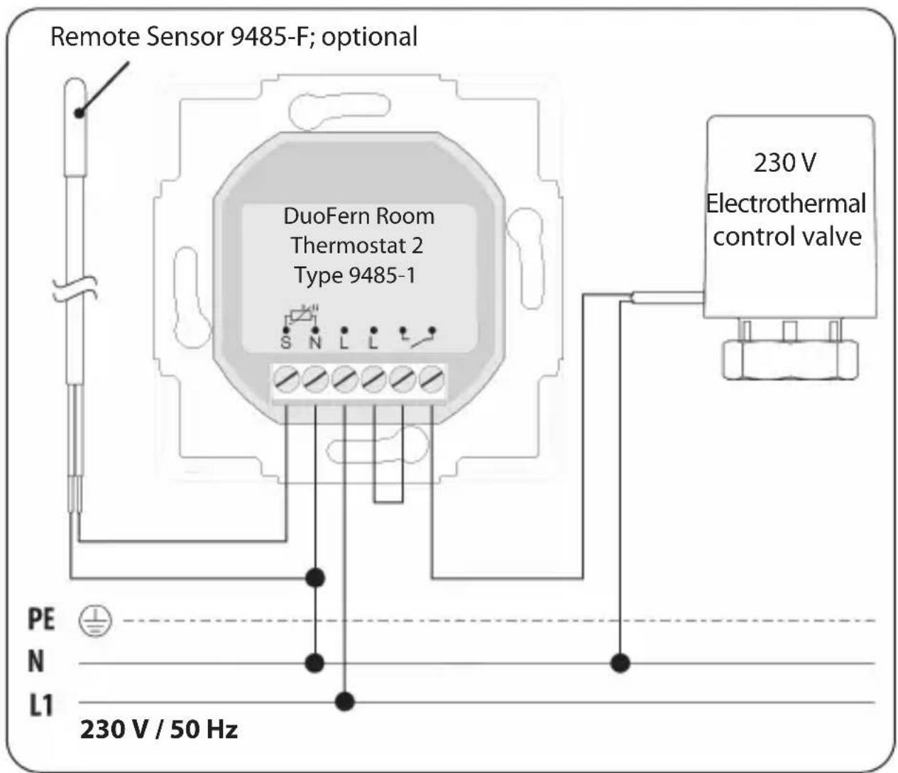
8.3 Connection diagram with a 230 V control valve....44
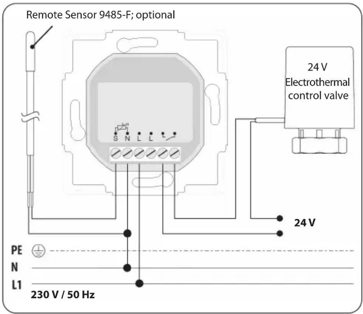
8.4 Connection diagram with a 24 V control valve......45
- Installation after the electrical connection 46
- Introduction to opening the menus and setting the functions 47
- Initial commissioning with the help of the installation wizard....49
- Manually changing the target temperature .... 53
- Switching automatic mode on/off directly on the standard display 54
- Calling up and displaying weather data....55
- Menu overview 57
15.1 Menu 1 - Switching automatic mode on/off....59
15.2 Menu 2 - Setting automatic heating phases 60
15.3 Menu 3 - Setting target temperatures centrally....75
- Menu 9 - System settings....77
16.1 Menu 9.1 - Setting the time and date....78
16.2 Menu 9.5 - Setting the week programme....79
16.3 Menu 9.7 - Installer settings 81
16.4 Menu 9.7.1 - Setting the heating mode 82
16.5 Menu 9.7.2 - Setting the sensor offset 86
16.6 Menu 9.7.3 - Setting the hysteresis / minimum on-time .... 87
16.7 Menu 9.7.4 - Setting the valve protection....88
16.8 Menu 9.7.5 - Setting the frost protection 89
16.9 Menu 9.7.6 - Setting the valve mode 90
16.10 Menu 9.7.7 - Performing a sensor test....92
17. Menu 9.8 - Device settings ...... 93
17.1 Menu 9.8.1 - Switching the automatic summer/ winter time on/off....94
17.2 Menu 9.8.3 - Setting the display lighting....95
17.3 Menu 9.8.5 - Switching the button lock on/off...... 96
17.4 Menu 9.8.6 - Setting the holiday mode incl. the setback temperature 98
17.5 Menu 9.8.7 - Setting the party mode incl. the comfort temperature ....100
17.6 Menu 9.8.0 - Displaying the software version....102
18. Menu 9.9 - DuoFern settings....103
18.1 Menu 9.9.1 - Logging DuoFern devices on/off....104
18.2 Menu 9.9.2 - Setting the DuoFern mode ...... 108
18.3 Menu 9.9.3 - Setting the transmission channel....110
18.4 Menu 9.9.4 - Switching the weather data on/off ....111
18.5 Menu 9.9.5 - Displaying the DuoFern address (radio code)....113
- Logging on to the HomePilot ^® ......114
- Deleting all settings, software reset 115
- Carrying out a hardware reset 116
- Error messages.... 117
- Dismantling 120
- Simplified EU Declaration of Conformity......121
- Accessories 121
- Warranty conditions 122

1. This manual...
...describes how to install, connect and operate the DuoFern Room Thermostat 2.

1.1 How to use this manual
Before you begin, please read this manual through completely and follow all the safety instructions
◆Please also read the instruction manuals of the accessories (if available) as well as the instructions of the respective connected electrical appliance
◆This manual is part of the product. Please store it in an easily accessible place
◆When passing the DuoFern Room Thermostat 2 on to a third party, this manual must be passed on as well
◆Damage resulting from non-compliance with these instructions and safety instructions will void the warranty. We assume no liability for any consequential damage.

2. Hazard symbols
EN
The following hazard symbols are used in this instruction manual:

Danger of fatal electric shock

Danger area / dangerous situation

2.1 Levels of danger and signal words

DANGER!
This hazard will lead to serious injury or death if not avoided.

WARNING! WARNING!
This hazard may result in serious injury or death if not avoided.

CAUTION!
This hazard may result in minor or moderate injury if not avoided.

ATTENTION!
This hazard may lead to property damage.
Depiction
Description
- Procedures
2.
Itemisation
1) or a)
Lists

Further useful information

Please read the respective manual
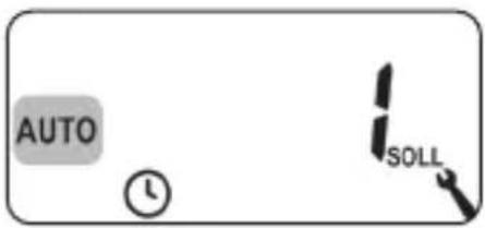
Flashing menu symbols and setting parameters have a grey background. Information about opening the menus and setting the parameters can be found on page 47.

The use of defective equipment can lead to personal injury and damage to property (electric shocks / short circuiting).
◆Never use defective or damaged equipment.
◆Check that the DuoFern Room Thermostat 2 is intact.
◆Consult our customer service department in the event that you discover damage, see page 124.

Improper use leads to an increased risk of injury.
◆Train all personnel to use the DuoFern Room Thermostat 2 safely.
◆Children must not play with the device.
◆Never remove the operating unit from the installation housing during operation.

Risk of damage due to the overheating or excessive cooling of the room or flooring.
The relay output remains unchanged if the operating unit is pulled out of the installation housing during operation. Control and limiting functions where appropriate are no longer provided.
◆Make sure that a relay state that poses no risk is set before removing the operating unit.
◆Switch off the central heating or air conditioning beforehand if necessary.
Use the DuoFern Room Thermostat 2 solely to control radiators / floor heating or the air conditioning within the permissible load limits, see page 34, Technical specifications.
The DuoFern Room Thermostat 2 is suitable for switching the mains voltage and extra-low voltage (ELV) with basic insulation.
Only use original spare parts and accessories from RADEMACHER
◆By doing so, you avoid the risk of malfunctions and damage to the DuoFern Room Thermostat 2
◆As the manufacturer, we provide no warranty for the use of third-party components and accept no liability for consequential damage resulting from such
Operating conditions
◆Only use the DuoFern Room Thermostat 2 in dry rooms
◆A 230 V/50 Hz power supply, together with a site-provided disconnecting device (fuse), must be available at the installation location
◆ The installation and operation of the radio systems is only permitted for those systems and devices where a malfunction in the transmitter or receiver would not cause a danger to personnel or property or where this risk is already covered by other safety equipment

Radio systems that transmit on the same frequency can cause interference.
Using the DuoFern Room Thermostat 2 for any other purpose than previously mentioned is not permissible.

Improper use can lead to serious injuries or property damage.
◆Do not use the DuoFern Room Thermostat 2 to disconnect the connected electrical appliance.
◆Never use the radio system (e.g. DuoFern radio system) and its components for the remote control of devices and systems with increased safety-relevant requirements or where there is an increased risk of accidents. Such applications require additional safety equipment. Observe the respective statutory regulations for the installation of such systems.

There is a risk of fatal injury caused by short circuiting and electric shocks if the DuoFern Room Thermostat 2 is used outdoors or in damp rooms.
◆ Do not install and use the DuoFern Room Thermostat 2 outdoors or in damp rooms.

3.3 Required expert knowledge of the installer
The electrical connection, installation and commissioning of the DuoFern Room Thermostat 2 must be carried out by a qualified electrician with basic heating control knowledge in accordance with the instructions in this manual.
UW
◆UW = ultra-white (device colour)
DIN 49075
◆German Standard "Cover panels for installation devices for building into device boxes..."
2014/53/EU
◆ European Radio Equipment Directive
ELV
◆Extra low voltage
Electrothermal control valves
Electrothermal valves with the switching states "normally closed (NC) or normally open (NO)" are often used for heating control.
You can set the respective valve mode on the DuoFern Room Thermostat 2 to adapt to the control valve used in each case.
Valve mode NC (normally closed)
◆The control valve remains closed in an isolated, de-energised state
Valve mode NO (normally open)
◆The control valve remains open in an isolated, de-energised state
Hysteresis / minimum on-time
◆This function prevents an unnecessary large number of switching operations by setting a minimum on-time
◆This prevents the DuoFern Room Thermostat 2 tripping too often if the room temperatures fluctuate
Offset (sensor offset)
◆The temperature measured on site can vary slightly from the room temperature if the DuoFern Room Thermostat 2 is installed in a unfavourable position (e.g. behind a curtain or on a cool exterior wall)
◆An adjustment of the measurement in the range of - 5.0°C to + 5.0 °C can be carried out using the sensor offset
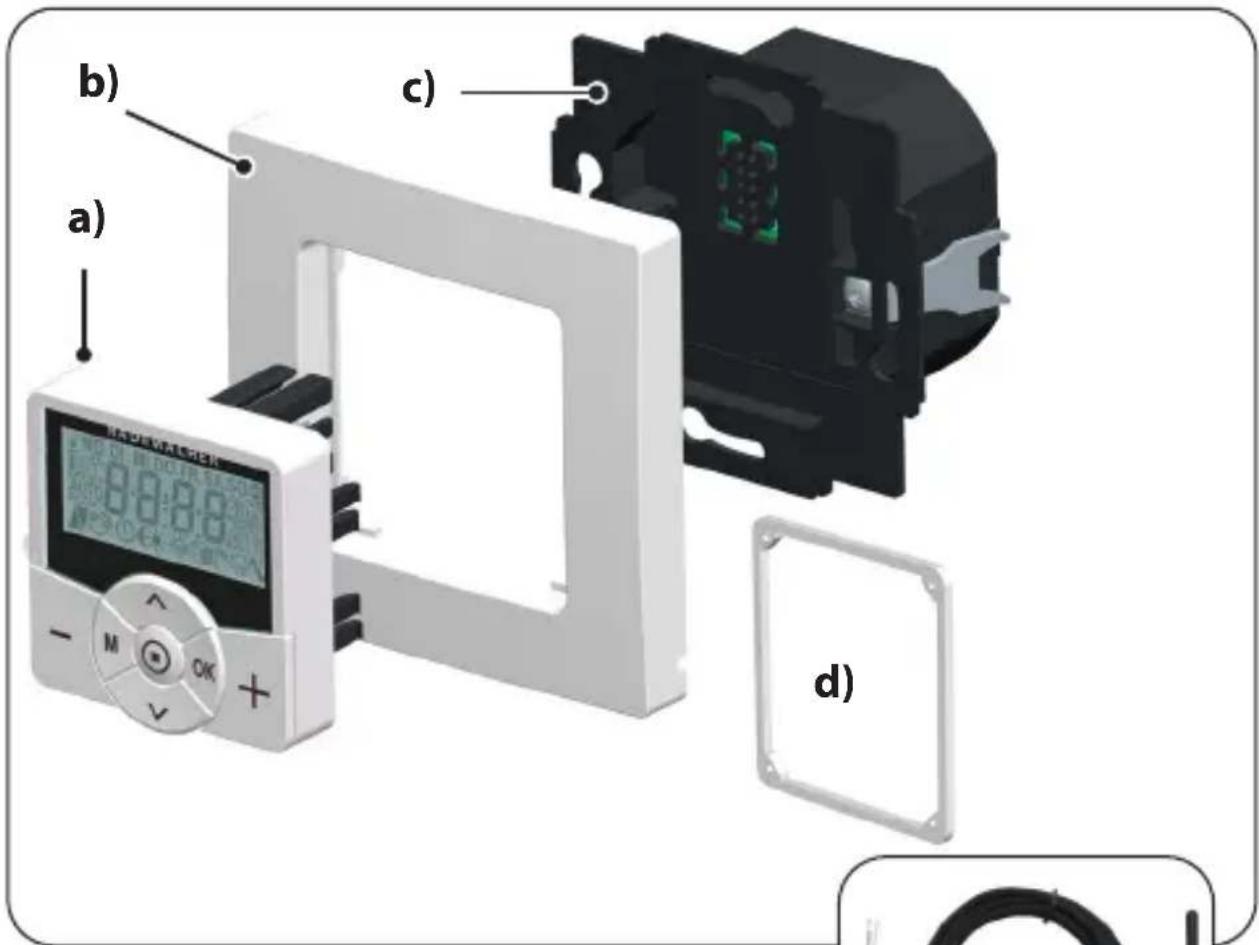
Included in delivery
a) 1 × Operating unit (50 x 50 mm)
b) 1 × Frame
c) 1 x Installation housing
d) 1 x Spacer frame, see page 46
e) 1 x Instruction manual (not illustrated)
natural_image
Coiled black cable with a small terminal connector, no text or symbols visibleAfter unpacking please check and compare...
... the contents of the package with those specified above.
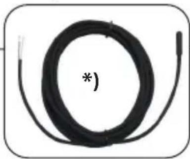
*) Accessories optionally available, see page 121
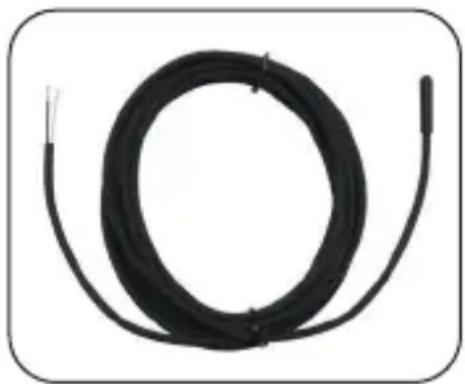
Remote Sensor 9485-F
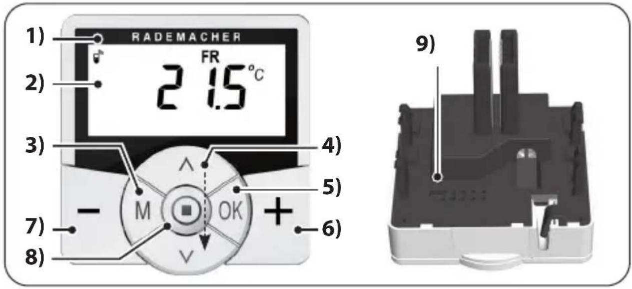
●Short press or press and hold = gradual or quick setting
◆Switch functions on / off (On / OFF)
◆Select the display (target (SOLL) / actual (IST) temperature / time)
Pos. Symbol Description
| 5) |  | OK button◆Open the selected menu◆Confirm and save settings◆Continue to the next setting |
| 6) |  | Plus button - HOTTER◆Gradually increase the target temperature by 0.5 °C |
| 7) |  | Minus button - COLDER◆Gradually reduce the target temperature by 0.5 °C |
| 8) SET |  | ◆Switch the button lock on/off(only when the button lock function is activated)◆Display weather information |
| 9) Bridging contact for a hardware reset | ||
| ◆See page 116 | ||
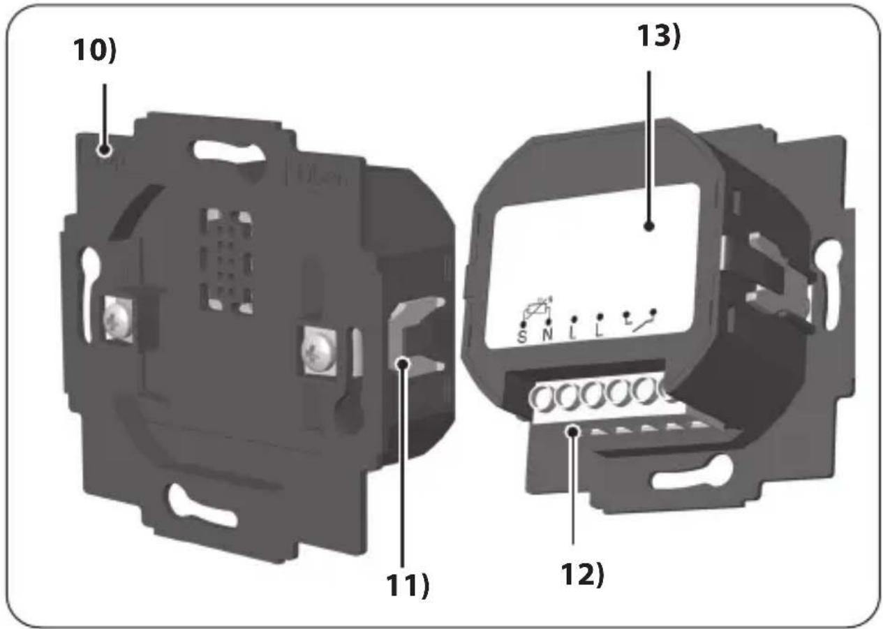
10) Installation housing
11) Claw fasteners and screws
12) Connecting terminals
13) Type plate
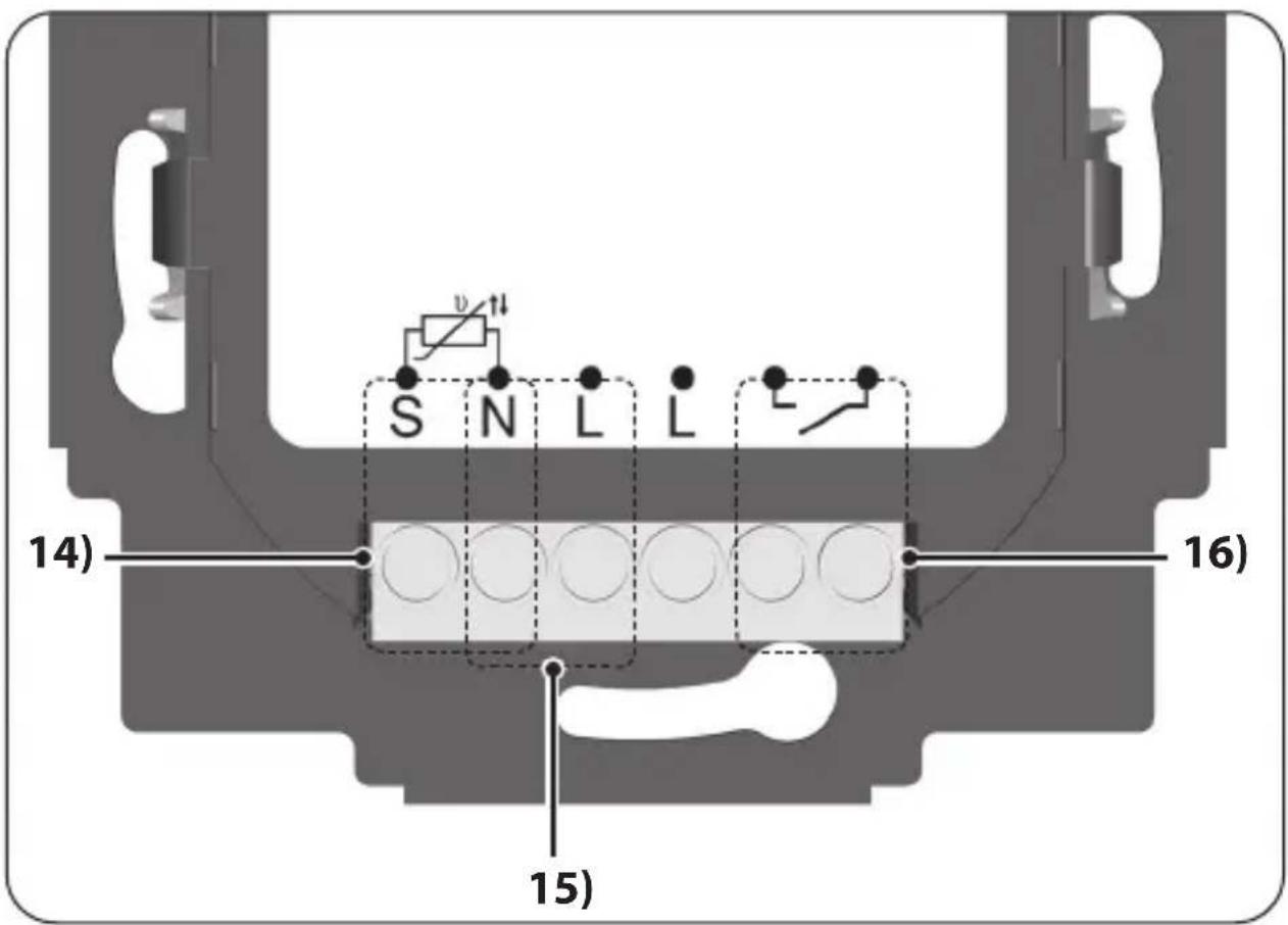
Connect the external Remote Sensor 9485-F to measure the room temperature.
15) Supply voltage [N/L] - 230 V / 50 Hz
N L
Connect the supply voltage.
16) Relay output - potential-free

Connect an electrothermal control valve (also with extra-low voltage) / electric heater or the air conditioning.
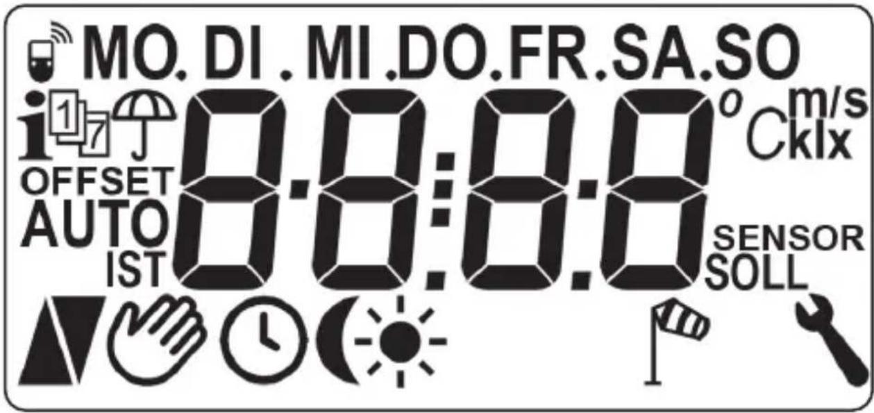
Pos. Symbol Description
17) MO... SO Weekdays (Monday...Sunday)
18) Time /setting parameters
19) DuoFern status
20) Weather information
21) Week programme
22) Rain display
23) OFFSET Sensor offset
24) AUTO Automatic mode
25)

Automatic mode off or manually changed target temperature
26) Heating

Pos. Symbol Description

27) Cooling
28) Switching times for the heating phases
29) Brightness display
30) Dusk display
31) Wind display
32) System settings
33) SOLL Target temperature
34) SENSOR Sensor test
35) klx/lx Light intensity (klx = Kilolux / lx = Lux)
36) °C Temperature unit in degrees Celsius
37) m/s Wind velocity (meters per second)
38) Automatic button lock

The DuoFern Room Thermostat 2 has adjustable LCD backlighting, see page 95, menu 9.8.3.
∧ / ∨ You can select the desired view of the standard display using the set buttons.
Target temperature
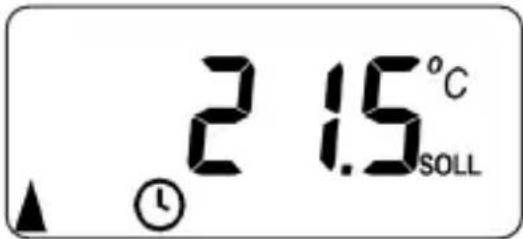
Symbols Description
21.5 °C SOLL The set target temperature
Actual temperature
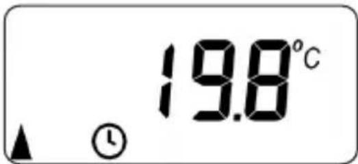
Symbols Description
19.8 °C The current room temperature
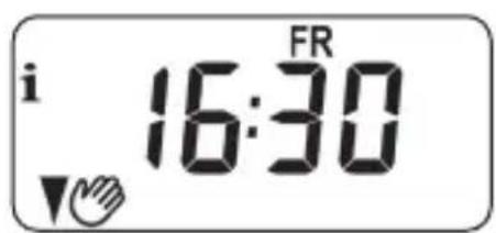
Time
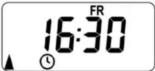
Symbols Description
FR
The current weekday
16:30 The current time

Other symbols can be displayed depending on the setting of the DuoFern Room Thermostat 2.
Examples:
| Symbols Description | |
| Automatic mode is active.Heating or cooling is provided at the set switching times until the room temperature reaches the target value. | |
| The target temperature has been manually changed. | |
| Heating is provided as the current room temperature is lower than the target temperature. | |
| Cooling is provided as the current room temperature is higher than the target temperature. | |
| The current weather information from a DuoFern Environmental Sensor is available. | |
| Wind or rain display | |
| Brightness or dusk display | |
The DuoFern Room Thermostat 2 automatically measures and controls the room temperature in individual rooms, e.g. by controlling a radiator, the floor heating or air conditioning. The temperature is either measured by the built-in sensor or by the optional external Remote Sensor 9485-F. The room thermostat has a potential-free relay output.
Support for three heating modes
The DuoFern Room Thermostat 2 can be used and configured in three different heating modes, see page 82:
◆Room temperature controller
◆Room temperature controller with limiter function
◆Cooling function
Furthermore, the DuoFern Room Thermostat 2 can be combined with the DuoFern Radiator Actuator 2 (item no. 3500 30 74, type: 9433-1) to control it.
Setting multiple heating phases
Up to six heating or cooling phases (incl. four target temperatures) can be set for each day.
Setting heating phases centrally in the HomePilot® or locally in the DuoFern Room Thermostat 2
The desired use is carried out by selecting the corresponding DuoFern mode in menu 9.9.2, see page 108.
Potential-free relay output
The following electrical appliances, for example, can be connected to the potential-free relay output:
◆Control valves (also extra-low voltage valves)
◆Heaters (also electrical heaters up to max. 2300 W)
◆Air conditioning
Connecting an external temperature sensor (optional)
The Remote Sensor 9485-F is optionally available as an external temperature sensor if the internal sensor cannot reliably record the room temperature. This may be useful if:
◆The DuoFern Room Thermostat 2 is installed in a thermally unfavourable position (e.g. on a cool exterior wall)
◆Heavy loads (e.g. an electric heater) are switched on that significantly heat up the DuoFern Room Thermostat 2 (self-heating)
When is it absolutely essential to use the external Remote Sensor 9485-F?
◆If you are using the DuoFern Room Thermostat 2 as a temperature limiter (e.g. for floor heating with special floor coverings).
Two valve modes (NC/NO) to adapt to the control valve used
Electrothermal valves with the switching states "normally closed (NC)" or "normally open (NO)" are often used for heating control.
You can set the respective valve mode in menu 9.7.6 to adapt to the control valve used in each case, see page 90.
Manual mode
The device is manually operated with the plus and minus button.
These buttons can be used to gradually increase or decrease the target temperature by 0.5 °C , see page 53.
Installation and electrical connection
The DuoFern Room Thermostat 2 is designed as a flush-mounted device for indoor rooms. The electrical connection is carried out by means of the connecting terminals on the reverse side of the installation housing.
Compatible switch ranges
The DuoFern Room Thermostat 2 can be integrated into standard switch range (50 x 50 mm).

It may be necessary to use an intermediate frame * 50 x 50 (according to DIN 49075) depending on the switch range used.
* Not included
◆For use as a local control on site or as a system solution (HomePilot® / DuoFern radio system)
◆Manual operation on site with the plus and minus buttons
◆AUTO / MANUAL switchover
◆Easy set-up thanks to the installation wizard
◆ Heating and cooling function depending on the connected device
◆Configurable for up to 6 switching times per day and any 4 target temperatures
◆ Optional external temperature sensor (Remote Sensor 9485-F) can be used for external temperature measurement or as a temperature limiter
◆Control of the valve / radiator or air conditioning in combination with a DuoFern actuator also by radio (ideal for retrofitting)
◆Combination with DuoFern Radiator Actuators 2 (item no. 3500 30 74, type: 9433-1) possible.
◆Two-step control (on/off) with configurable hysteresis and adjustable minimum switching time
◆Target temperature can also be manually changed by the manual transmitter
◆Receipt and display of weather data (temperature, brightness, wind velocity and rain) in combination with a DuoFern Environmental Sensor
◆Three different week programmes
◆Automatic button lock
◆Dimming of the LCD backlighting
◆Sensor test
◆Delete or reset all data
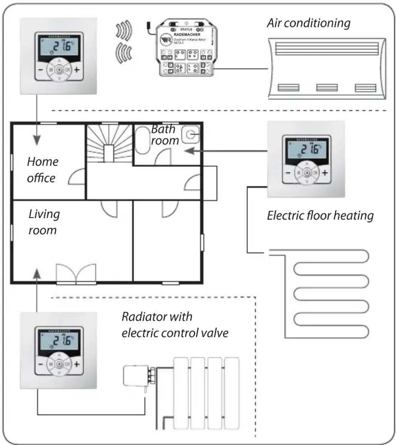
Sample application 1
DuoFern Room Thermostat 2 for individual room regulation of radiators, floor heating or the air conditioning.
flowchart
graph TD
    A["Air conditioning"] --> B["Home office"]
    B --> C["Living room"]
    C --> D["Bath room"]
    D --> E["Radiator with electric control valve"]
    E --> F["Electric floor heating"]
    F --> G["Air conditioning unit"]
    style A fill:#f9f,stroke:#333
    style B fill:#ccf,stroke:#333
    style C fill:#cfc,stroke:#333
    style D fill:#fcc,stroke:#333
    style E fill:#cff,stroke:#333
    style F fill:#ffc,stroke:#333
    style G fill:#cfc,stroke:#333
Home office
Control the air conditioning by radio using a DuoFern Universal actuator (e.g. for retrofitting without cabling between the DuoFern Room Thermostat 2 and the air conditioning).
Bathroom
Directly connect and control electric floor heating.
Living room
Directly connect an electrothermal control valve to control a radiator.
Sample application 2
Several DuoFern Room Thermostats 9485 for individual room regulation of floor heating using DuoFern actuators.
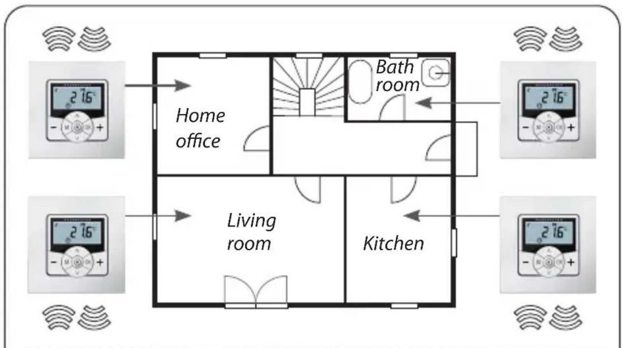
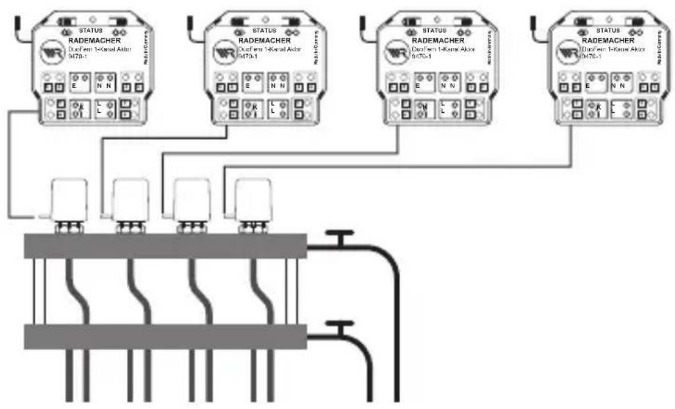
An individual DuoFern Universal actuator for each room in the cellar, which regulates the control valves.
flowchart
graph TD
    A["STATUS RADEMACHER\nDuxFerr 1-Karal Aktor 9470-1"] --> B["INPUT"]
    C["STATUS RADEMACHER\nDuxFerr 1-Karal Aktor 9470-1"] --> D["OUTPUT"]
    E["STATUS RADEMACHER\nDuxFerr 1-Karal Aktor 9470-1"] --> F["INPUT"]
    G["STATUS RADEMACHER\nDuxFerr 1-Karal Aktor 9470-1"] --> H["OUTPUT"]
A DuoFern Universal actuator (1-channel) per room in the cellar:
◆This receives the switching commands directly from the respective DuoFern Room Thermostat 2, thus regulating the control valves (e.g. for retrofitting if no leads to the heating manifold are present.)
◆The parallel connection of several control valves from one room to one 1-channel Universal actuator each is possible

There is a risk of an unintentional or erroneous influence through automated scenes or manual operation.
◆A DuoFern actuator logged on to the DuoFern Room Thermostat 2 must not be logged on to the HomePilot® or to other DuoFern controllers (e.g. DuoFern manual transmitters).
Sample application 3
Central control through the HomePilot®
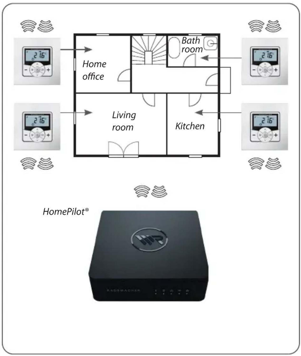
The DuoFern Room Thermostat 2 can be connected to the HomePilot®. This means that the following functions can be used:
◆The target temperature and display of the current state (actual temperature, target temperature etc.) can be changed manually with smartphone apps
◆The four saved target temperatures can be changed at any time via the HomePilot® web interface
◆Scenes can be triggered in the HomePilot® if the temperature drops below or exceeds the four saved target temperature values
◆The DuoFern Room Thermostat 2 must be operated in mode 1 (DuoFern receiver) to control the heating phases through scenes in the HomePilot®

Direct access from the HomePilot ^® to the relay switching state is not possible.
◆The switching of the relay is always dependent on the target and actual temperature.
Sample application 4
DuoFern Room Thermostat 2 for group control of DuoFern Radiator Actuators 2
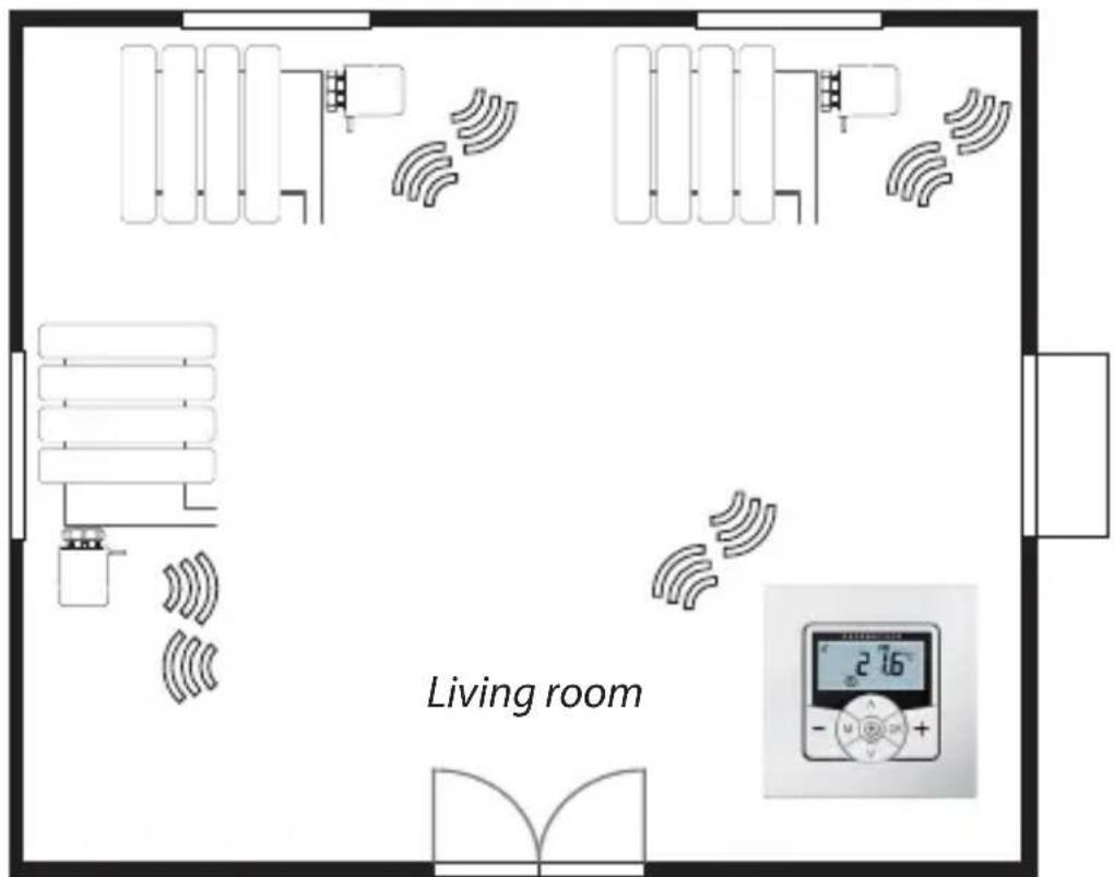
HomePilot® (optional)

natural_image
Black electronic device labeled 'HP' with control buttons and display screen (no readable text beyond branding)Self-sufficient system
◆ Control of up to 20 DuoFern Radiator Actuators
◆Central control: the target temperature is sent from the DuoFern Room Thermostat 2 to all DuoFern Radiator Actuators 2
Control via HomePilot®
◆Only the DuoFern Room Thermostat 2 is registered on HomePilot®.
◆Commands are transmitted centrally from the DuoFern Room Thermostat 2 to the DuoFern Radiator Actuators 2

Optionally, the measured actual temperature of the DuoFern Room Thermostat 2 can be used as the controlled variable for the DuoFern Radiator Actuators 2.
Use therefore the menu item "SEn" of the DuoFern Radiator Actuator 2.
| Mains supply [L/N] | |
| Mains supply voltage: | 230 V / 50 Hz ~ |
| Consumption: Standby: < 0.4 W | |
| Sensor input [ S / N ] -e.g. to connect the Remote Sensor 9485-F | |
| Requirement: double insulated | |
| R25: 10 kΩ | |
| B: 3977 | |
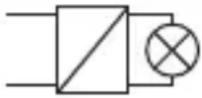
| Relay output - load contact for 230 V [ ] | ||
| Switching voltage: 230 V / 50 Hz ~ | ||
| Maximum switching capacity: | ohmic load | |
| 10 A μ / 2300 W | ||
| inductive loads: | ||
| 5 A μ / 1115 VA | ||
| Maximum switching capacity: | capacitive loads | |
 | 5 A μ / 1115 VA | |

Improper use can lead to serious injuries or property damage.
◆Due to the small contact distance ( ), not suitable for disconnecting.
◆Do not use the DuoFern Room Thermostat 2 to disconnect the connected electrical appliance.
| DuoFern radio technology | |
| Transmission frequency: 434.5 MHz | |
| Transmission power: max. 10 mW | |
| Range: | in buildings: approx. 30 m * outdoors: approx. 100 m* depending on the building structure |
| Max. number of DuoFern devices: | 20 |
| General information | |
| External dimensions(W x H x D)Operating unit [ 1 ]: | 50 x 50 x 12 mmaccording to DIN 49075 |
| Available colours: ultra-white (UW), glossy | |
| Installation depth: | 32 mm |
| Permissible ambient temperature range: | 0 °C to + 40 °C |
| Protection class: II | |
| Protection type: IP 30 (only for use in dry rooms) | |
| Connecting terminals: | Screw terminals for max.1.5 mm^2 cable cross-section |
| Power reserve for clock in the event of a power failure | approx. 8 hours |
| Factory settings | |
| Automatic mode: off | |
| Automatic time: off | |
| Hot (21.5 °C) from: 06:00 | |
| Cold (17.0 °C) from: 23:00 | |
| Target temp. 1 and 3: 21.5 °C | |
| Target temp. 2 and 4: 17.0 °C | |
| Weekly programme: off | |
| Automatic summer/winter changeover: | on |
| Standard display: target temperature | |
| Heating mode: 1 (room temperature controller) | |
| Hysteresis: 0.2 °C | |
| Min. on-time / off-time: 2 minutes | |
| Valve protection: off | |
| Frost protection: on; 4.0°C | |
| Valve mode: NC (energised heating) | |
| Quick changeover to temperature value: | |
| - with + (hot): | off |
| - with - (cold): | off |
| DuoFern transmission channel: | channel 1 |
Power reserve (approx. 8 hours)
The current time flashes for approx. 5 minutes in the event of a power failure and the DuoFern room thermostat changes to power reserve.
Time and date after a power failure
The power reserve is approx. 8 hours. If this time is exceeded, the time and date are lost and need to be reset, see page 78.

The internal timer works with tolerances in power reserve mode. It may therefore be necessary to adjust the time after a longer power failure.
Data retention following a power failure
All settings remain permanently saved. Data is not lost even after a longer power failure.
Prior to the electrical connection, check that the voltage / frequency on the type plate corresponds to that of the local mains supply.

Read the specifications relating to the electrical connection detailed in the instruction manual of the electrical appliance used.

DANGER!
There is a risk of fatal electric shock when touching electrical components.
◆All connection and installation work must only be carried out in a de-energised state.
◆Disconnect all phases of the mains power cable and secure it to prevent any reconnection.
◆Check that the system is de-energised.

WARNING! WARNING!
There is a risk of fatal injury caused by short circuiting when the DuoFern Room Thermostat 2 is overloaded.
The maximum switching capacity must not be exceeded, for this, please observe the details in the technical specifications, see page 34.

WARNING! WARNING!
Using an incorrect installation housing can lead to personal injury and damage to property (electric shocks / short circuiting).
◆Only use the installation housing provided to connect and install the DuoFern Room Thermostat 2.
◆Installation housings of other RADEMACHER products are not compatible.

WARNING! WARNING!
Incorrect wiring may lead to short circuits and destroy the device.
Follow the pin assignment detailed in the connection diagram.
Potential-free relay output
The relay is potential-free. Control valves and controllers that require a different supply voltage can also be connected (e.g. 24 V). One side of the relay contact should be set to the respective control voltage (e.g. +24 V) instead of [L] in this case, see page 45.
Only switch extra-low voltage with basic insulation
Only extra-low voltages (ELV) with basic insulation may be connected and switched.
Installation materials
The DuoFern Room Thermostat 2 is intended for flush mounting. We recommend installation in a deep 58 mm flush-mounted box or in an electronic socket.
Length of insulation stripped:
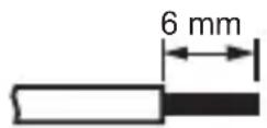
All leads must be stripped to 6 mm.
Optional connection of the external Remote Sensor 9485-F
The external Remote Sensor 9485-F can optionally be connected for temperature measurement if the DuoFern Room Thermostat 2 is installed in a thermally unfavourable position.
natural_image
Black cable with two leads, no visible text or symbolsAbsolutely essential use of the external Remote Sensor 9485-F
It is absolutely essential that the Remote Sensor 9485 is connected when using limiting functions (heating mode 2 = room temperature controller with limiter).
Maximum length of lead to connect the external Remote Sensor 9485-F
The maximum length of lead to connect the external Remote Sensor 9485-F must not exceed 10 m.

8.2 Electrical connection
EN
- Ensure the mains is disconnected and check whether the mains power cables are current-free.
- Securely lay all connecting cables right into the flush-mounted box.
- Remove the insulation on all leads down to 6 mm in length and connect them according to the connection diagram on the following pages.
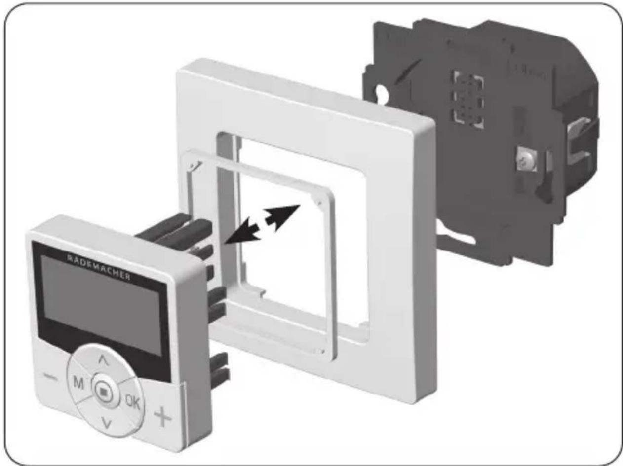
- After the electrical connection, the installation of the DuoFern Room Thermostat 2 into the flush-mounted box is carried out, see page 46.
natural_image
3D rendering of a device with a digital display and internal components, showing no visible text or symbols.- Insert the installation housing into the flush-mounted box and fasten it with the screws of the claw fasteners.
- Place the frame on to the installation housing.
- Place the spacer frame in the frame.
- Then carefully insert the operating unit into the installation housing.
- Switch on the mains power supply again.
i
10. Introduction to opening the menus and setting the functions
EN
- M Open the main menu.
Pressing the menu button in the standard display opens the main menu.
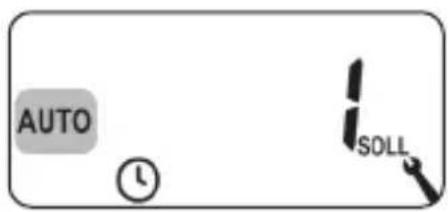
- /^ Select the desired menu.
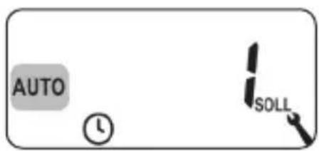
The selected menu is indicated by a flashing symbol.
- OK Confirm and open the selected menu.
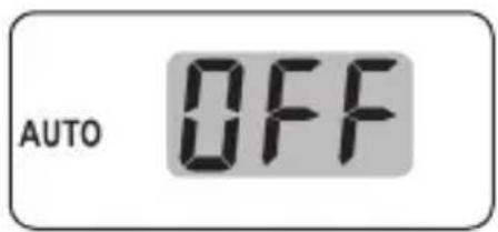
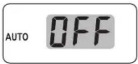
OFF flashes.
i
10. Introduction to opening the menus and setting the functions
EN
- /Select the desired setting (e.g. On).
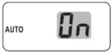
- OK Each setting must be confirmed with the OK button.
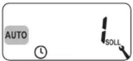
Confirming the entry takes you to the next setting or back to the menu.
- M Back to the standard display.
Example

Pressing the menu button briefly takes you back one menu step. Pressing and holding the button always take you to the standard display.
The installation wizard, which guides you through the first basic settings, is automatically started for the initial commissioning or after a software reset.
Continue with menu 9.7 "Installer settings"
The settings in menu 9.7 must be checked and adapted to the existing heating installation after completing the installation wizard, see page 81.
Readiness for operation
The DuoFern Room Thermostat 2 is ready for operation after completing the settings mentioned above.
i
11. Initial commissioning with the help of the installation wizard
EN
- The installation wizard is shown after switching on the mains voltage. The digits start flashing.
- Set and confirm the current time.
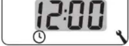
- Set the current date (day. month), and confirm each setting.
- Set and confirm the current year.
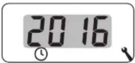
- Set and confirm the starting time of the first heating phase. 6:00 Factory setting = 06:00
Maximum number of daily heating phases
A maximum of six heating phases can be set up for each day, see page 60, menu 2.
Pre-setting the week programme
The first starting time applies to the entire week (MO...SO).
If necessary, you can then select one of three week programmes in menu 9.5, see page 79.
i
11. Initial commissioning with the help of the installation wizard
EN
Assigning different target temperatures
Each heating phase can be assigned an individual target temperature. You can set four target temperatures and assign any number of heating phases, see page 60, menu 2.
6.
Select and confirm the number of the
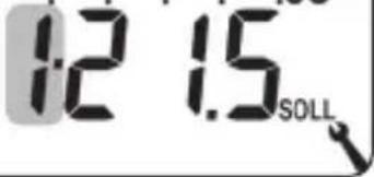
desired target temperature for this heating phase.
7.
MO.
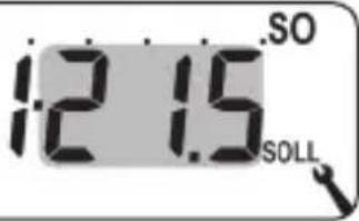
Set and confirm the desired target temperature.
Factory setting = 1·21.5 °C
8.
Set and confirm the starting time of
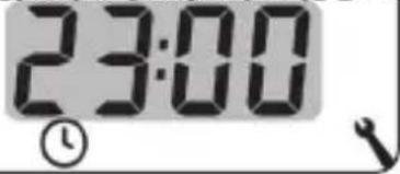
the second heating phase.
Factory setting = 23:00
9.
Select and confirm the number of the
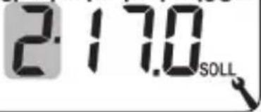
desired target temperature for this heating phase.
10.
Set and confirm the desired target
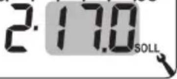
temperature.
Factory setting = 2·17.0 °C
i
11. Initial commissioning with the help of the installation wizard
EN
11.
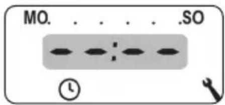
Set the starting time of the next heating phase (see points 8 to 10.).
or
Exit the settings in the installation wizard by selecting and confirming

12.
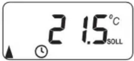
The standard display is shown after the final setting.
Example
- The settings in menu 9.7 must be checked and adapted to the local heating installation after completing the installation wizard, see page 81.
If necessary you can manually change the target temperatures of the automatic heating phases temporarily. The change is made on the standard display.

(Hotter) Gradually increase the target temperature 0.5^ C .
(Colder) Gradually reduce the target temperature 0.5^ C .
Display example:
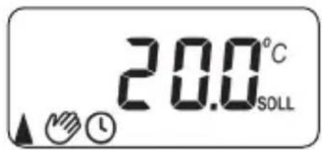

The target temperature has been manually changed.

The manual change only applies until the next automatic heating phase becomes active at the set switching time.
Resetting the manual change

1 sec. Press the OK button on the standard display one second to reset the manual change.
The automatic mode with its set heating phases and target temperatures then applies again.
13. Switching automatic mode on/off directly on the standard display

Automatic mode on
◆All previously set automatic functions are active.
◆Manual operation is also possible in automatic mode.

Automatic mode off
◆All set automatic functions are deactivated.
- OK 1 sec. Press the OK button for one second on the standard display.
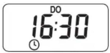
Automatic mode on
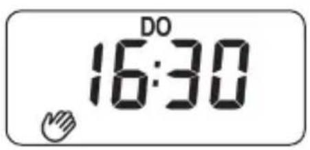
Automatic mode off

If the target temperature was previously changed, you have only reset the manual change of the target temperature in the first step.
◆Press the OK button again in this case to switch off automatic mode.
The DuoFern Room Thermostat 2 can receive and display weather data (temperature, brightness, wind velocity and rain) from a DuoFern Environmental Sensor. It is not necessary to log the DuoFern Environmental Sensor on to the DuoFern Room Thermostat 2.

Environmental sensors update the weather data approx. every 5 minutes and therefore it can take a few minutes until the weather data is displayed.
◆If no new weather data is received for 45 minutes, this is no longer available.

In the event that multiple DuoFern Environmental Sensors are being received, the desired environmental sensor can be selected in menu 9.9.4, see page 111.
- As soon as an environmental sensor is detected, the corresponding symbol is shown on the display.
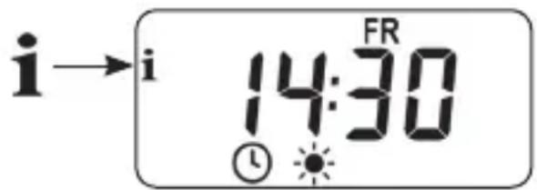
- Pressing the SET button briefly displays the first weather data.
i
14. Calling up and displaying weather data
EN
- /∧ You can call up all the available weather data using the set buttons, see examples.
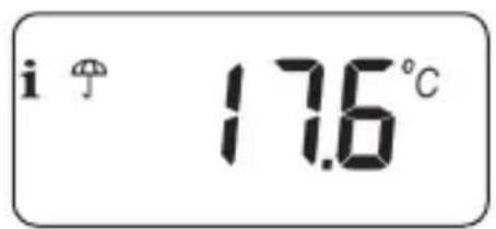
Temperature and rain
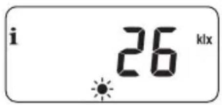
Brightness
$$ 0 - 9 9 9 \mathrm{Lux} = \mathrm{Ix} $$
$$ 1 - 1 5 0 \mathrm{kilo} \mathrm{lux} = \mathrm{klx} $$
Symbol depending on the brightness:
$$ < 5 0 \mathrm{lx} = (\text { musk }) $$
$$
5 0 \mathrm{lx} = $$

Wind velocity
$$ 0 - 3 5 \mathrm{m} / \mathrm{s} $$
Exiting the weather data display
- Pressing the SET button briefly exits the weather data display.

The display automatically switches to the standard display after 10 seconds.
Main menu
Symbol Menu Page
AUTO / Automatic mode....59
2 Switching times / automatic heating phases .....60
SOLL 3 Target temperatures / numbers .....75
9 System settings....77
SET 9.1 Time and date ....78
17 9.5 Week programme....79
i 9.7 Installer settings ....81
9.7.1 Heating mode....82
OFFSET 9.7.2 Sensor offset 86
H 9.7.3 Hysteresis and minimum on-time....87
9.7.4 Valve protection 88
9.7.5 Frost protection 89
9.7.6 Valve mode 90
SENSOR 9.7.7 Sensor test 92


9.8 Device settings....93
9.8.1 Automatic summer / winter changeover....94
9.8.3 Display lighting 95
9.8.5 Button lock 96
9.8.6 Holiday mode 98
9.8.7 Party mode 100
9.8.0 Software version 102
9.9 DuoFern settings 103
9.9.1 Logging on and off....104
9.9.2 Setting the DuoFern mode ..... 108
Ch 9.9.3 Setting the transmission channel ..... 110


9.9.4 Switching the weather data on/off ..... 111
9.9.5 Displaying the DuoFern address (radio code) ....113

Standardised menu structure
A standardised, cross-product menu structure has been developed for all RADEMACHER devices.
Similar functions always have the same menu number and therefore there may be gaps in the numbering.
AUTO
15.1 Menu 1 - Switching automatic mode on/off
EN

Automatic mode on (symbol on the standard display)
◆All set automatic functions are active
◆Manual operation is also possible in automatic mode

Automatic mode off (symbol on the standard display)
◆All automatic functions are deactivated

Both symbols on the standard display

◆Automatic mode on and the target temperature has been manually changed - the change applies to the next heating phase
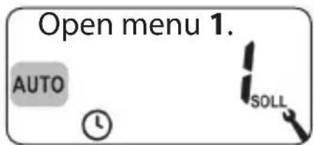
Switching automatic mode on/off in menu 1
1.
2.
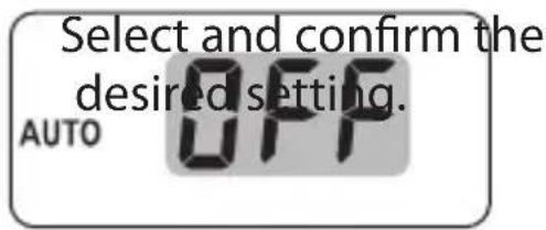
OFF = Automatic mode off
On = Automatic mode on
Toggling directly on the standard display
OK 1 sec. Press the OK button for one second on the standard display.
You can set automatic heating phases for each day with the desired switching time and target temperature.
Maximum number of daily heating phases
A maximum of six heating phases can be set up for each day.
Pre-setting the week programme
First select the desired week programme in menu 9.5, see page 79.
Additional information about the setting:
◆The switching times of the heating phases are set in 15 minute steps (e.g. 06:00, 06:15, 06:30 etc.)
◆A new heating phase cannot be set before the previous heating phase
◆Four adjustable target temperatures are stored. These can be randomly assigned to the individual heating phases
◆If the setting of a heating phase sequence should be terminated, select and confirm the next switching time with:
◆ The setting of the heating phases can also be terminated by pressing and holding the SET button
We show you three examples below for the setting of automatic heating phases:
Example 1 Family programme
The automatic heating phases should apply for the entire week (Mon - Sun) [MO - SO].
Example 2 Single household
The automatic heating phases should be set separately for the weekdays (Mon - Fri) [MO - FR] and the weekend (Sat - Sun) [SA -SO].
Example 3 Home office
Heating should only be provided on Friday and Saturday.
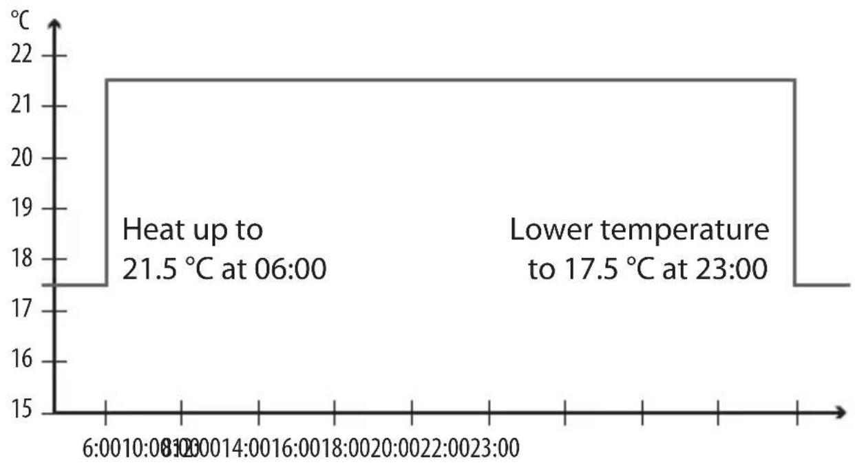
Example 1 Setting (family programme)
The room temperature is regulated to the desired target temperature or setback temperature at the same switching times on all weekdays.
line
| Time | Temperature (°C) | | :--- | :--- | | 6:00-10:00 | 17.5 | | 10:00-14:00 | 21.5 | | 14:00-18:00 | 21.5 | | 18:00-20:00 | 21.5 | | 20:00-22:00 | 21.5 | | 22:00-23:00 | 17.5 |MO.....SO (Monday.....Sunday)
| Heating phase | Time | Target temperature (SOLL) | |
| No. °C | |||
| 1 06:00 | 1 21.5 °C | ||
| 2 23:00 | 2 17.5 °C | ||
| 3 | |||

15.2 Menu 2 - Setting automatic heating phases
EN
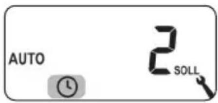
- First open menu 9.5 and set the week programme [1].
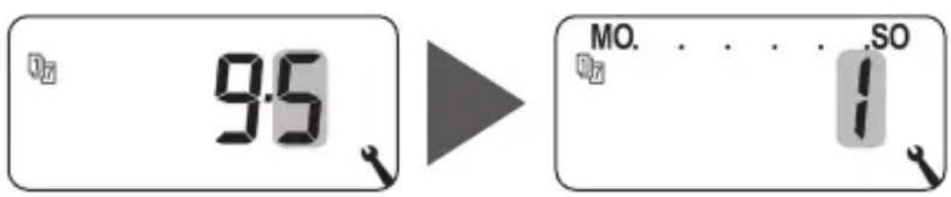
- Then menu 2 opens automatically
or
Open menu 2 if the desired week programme is already active.
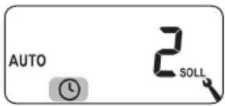
- Set and confirm the starting time of
the first heating phase.
e.g. 06:00
- Select and confirm the number of the
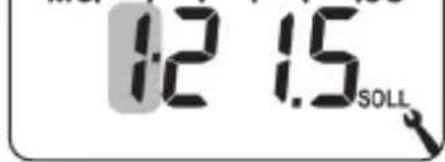
desired target temperature for this heating phase, e.g. 1.
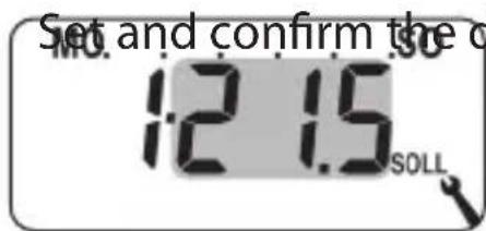
- Set and confirm the desired target
temperature.
e.g. 21.5 °C

15.2 Menu 2 - Setting automatic heating phases
EN
6.
Set and confirm the starting time of
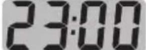
the second heating phase.
①
e.g. 23:00
7.
MO. . . . . SO

Select and confirm the number of the desired target temperature for this heating phase, e.g. 2.
8.
Set and confirm the desired target

temperature (e.g. setback temperature).
e.g. 17.0^ C
9.
MO. . . . . .SO
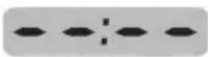
Terminate and confirm the setting of the heating phases.
①
10.
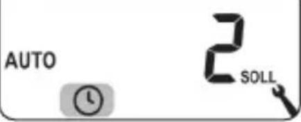
Subsequently the main menu is displayed
or
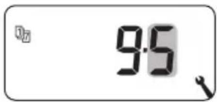
Menu 9.5.
Example 2 Setting (single household)
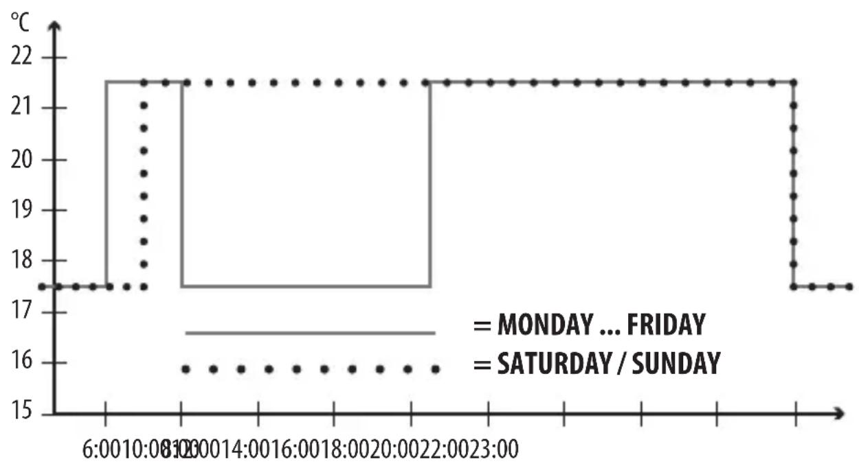
The room temperature should be regulated to different temperatures at different times on weekdays and at the weekend.
line
| Time | Temperature (°C) | | -------- | ---------------- | | 6:00 | 17 | | 8:00 | 21 | | 10:00 | 21 | | 12:00 | 21 | | 14:00 | 21 | | 16:00 | 21 | | 18:00 | 21 | | 20:00 | 21 | | 22:00 | 21 | | 23:00 | 17 |MO....FR (Monday .... Friday)
| Heating phase | Time | Target temperature (SOLL) | |
| No. °C | |||
| 1 06:00 | 1 21.5 °C | ||
| 2 08:00 | 2 17.5 °C | ||
| 3 14:30 | 1 21.5 °C | ||
| 4 23:00 | 2 17.5 °C | ||
| 5 | |||
| SA SO (Saturday / Sunday) | |||
| Heating phase | Time | Target temperature (SOLL)No. °C | |
| 1 07:00 | 1 21.5 °C | ||
| 2 23:00 | 2 17.5 °C | ||
| 3 | |||
SA SO (Saturday / Sunday)
- First open menu 9.5 and set the week programme [2].
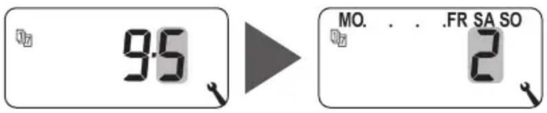
- Then menu 2 opens automatically
or
Open menu 2 if the desired week programme is already active.

15.2 Menu 2 - Setting automatic heating phases
EN
- Set and confirm the starting time of
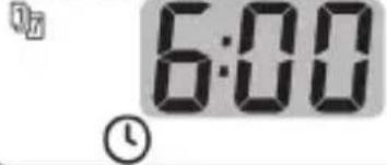
the first heating phase.
e.g. 06:00
-
MO DI MI DO FR 1.2 1.5°C SOLL Select and confirm the number of the desired target temperature for this heating phase, e.g. 1.
-
MO DI MI DO FR 12 15°C Set and confirm the desired target temperature.

e.g. 21.5 °C
- Set and confirm the starting time of
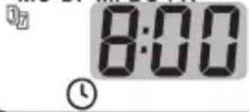
the second heating phase.
e.g. 08:00
- MO DI MI DO FR 2.170°C SOLL Select and confirm the number of the desired target temperature for this heating phase, e.g. 2.
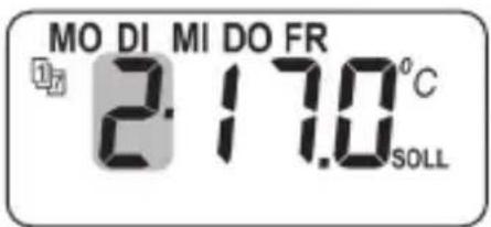
Set and confirm the desired target temperature (e.g. setback temperature).
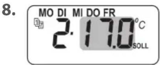
e.g. 17.0^ C

15.2 Menu 2 - Setting automatic heating phases
EN
9.
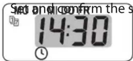
the third heating phase.
e.g. 14:30
10.
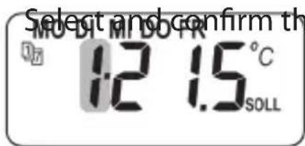
desired target temperature for this heating phase, e.g. 1.*
11.
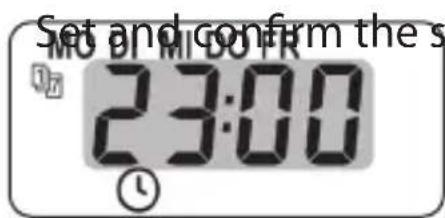
the fourth heating phase.
e.g. 23:00
12.
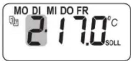
Select and confirm the number of the desired target temperature for this heating phase, e.g. 2.*

*
The selected target temperatures cannot be changed because they are already used as they are already elsewhere in a heating phase.
13.
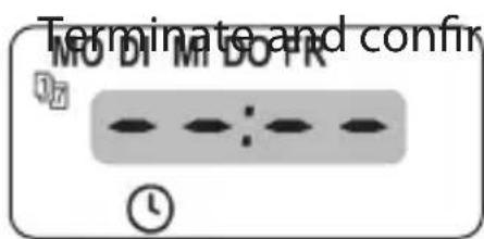
the heating phases for the weekdays Monday - Friday (MO - FR).
Setting the heating phases for Saturday / Sunday (SA/SO)
14.
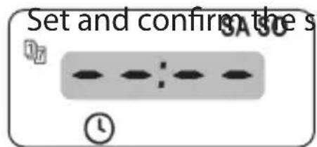
of the first heating phase for the weekend.
e.g. 07:00
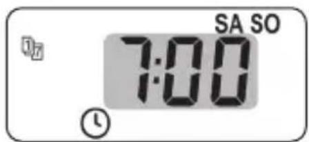
15.
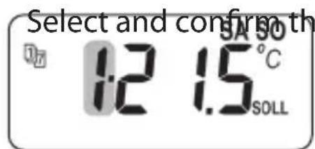
desired target temperature for this heating phase, e.g. 1.*
16.
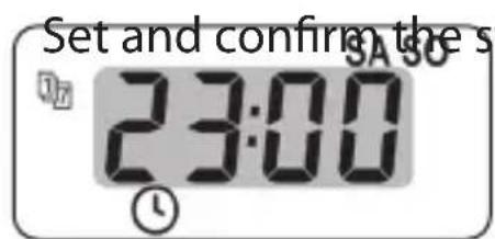
of the second heating phase for the weekend.
e.g. 23:00
17.
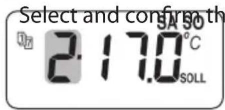
desired target temperature for this heating phase, e.g. 2. *

*
The selected target temperatures cannot be changed because they are already used as they are already elsewhere in a heating phase.

15.2 Menu 2 - Setting automatic heating phases
EN
18.
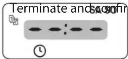
the settings for the weekend Saturday/Sunday (SA / SO).
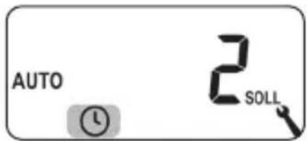
19.
Subsequently the main menu is displayed
or
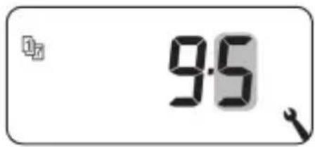
Menu 9.5.
Example 3 Setting (home office)
Heating should only be provided on Friday and Saturday. The room temperature should be regulated to the setback temperature on all other days.
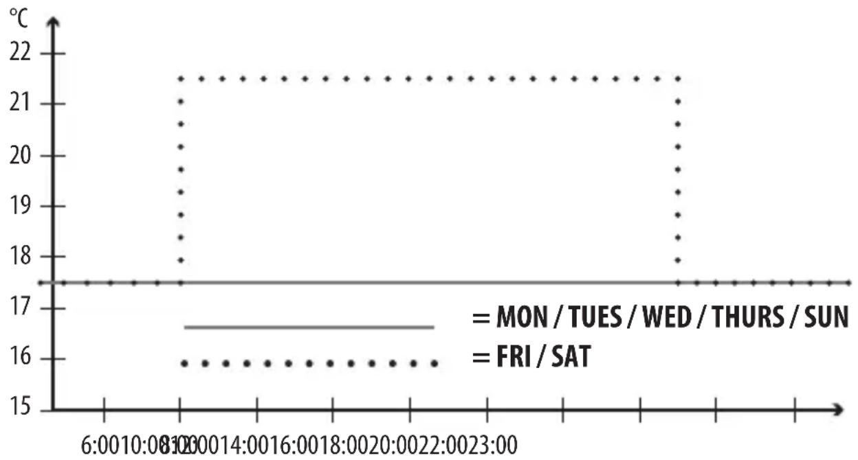
line
| Time | Temperature (°C) | | :--- | :--- | | 6:00-10:00 | 17 | | 10:00-14:00 | 17 | | 14:00-18:00 | 17 | | 18:00-22:00 | 17 | | 22:00-23:00 | 17 | | 23:00-24:00 | 17 | | 24:00-25:00 | 17 | | 25:00-26:00 | 17 | | 26:00-27:00 | 17 | | 27:00-28:00 | 17 | | 28:00-29:00 | 17 | | 29:00-30:00 | 17 | | 30:00-31:00 | 17 | | 31:00-32:00 | 17 | | 32:00-33:00 | 17 | | 33:00-34:00 | 17 | | 34:00-35:00 | 17 | | 35:00-36:00 | 17 | | 36:00-37:00 | 17 | | 37:00-38:00 | 17 | | 38:00-39:00 | 17 | | 39:00-40:00 | 17 | | 40:00-41:00 | 17 | | 41:00-42:00 | 17 | | 42:00-43:00 | 17 | | 43:00-44:00 | 17 | | 44:00-45:00 | 17 | | 45:00-46:00 | 17 | | 46:00-47:00 | 17 | | 47:00-48:00 | 17 | | 48:00-49:00 | 17 | | 49:00-50:00 | 17 | | 50:00-51:00 | 17 | | 51:00-52:00 | 17 | | 52:00-53:00 | 17 | | 53:00-54:00 | 17 | | 54:00-55:00 | 17 | | 55:00-56:00 | 17 | | 56:00-57:00 | 17 | | 57:00-58:00 | 17 | | 58:00-59:00 | 17 | | 59:00-60:00 | 17 | | 60:00-61:00 | 17 | | 61:00-62:00 | 17 | | 62:00-63:00 | 17 | | 63:00-64:00 | 17 | | 64:00-65:00 | 17 | | 65:00-66:00 | 17 | | 66:00-67:00 | 17 | | 67:00-68:00 | 17 | | 68:00-69:00 | 17 | | 69:00-70:00 | 17 | | 70:00-71:00 | 17 | | 71:00-72:00 | 17 | | 72:00-73:00 | 17 | | 73:00-74:00 | 17 | | 74:00-75:00 | 17 | | 75:00-76:00 | 17 | | 76:00-77:00 | 17 | | 77:00-78:00 | 17 | | 78:00-79:00 | 17 | | 79:00-80:00 | 17 | | 80:00-81:00 | 17 | | 81:00-82:00 | 17 | | 82:00-83:00 | 17 | | 83:00-84:00 | 17 | | 84:00-85:00 | 17 | | 85:00-86:00 | 17 | | 86:00-87:00 | 17 | | 87:00-88:00 | 17 | | 88:00-89:0MO / DI / MI / DO + SO (Mo / Tues / Wed / Thurs + Sun)
| Heating phase | Time | Target temperature (SOLL) No. °C | |
| 1 | |||
FR + SA (Friday + Saturday)
| 1 08:00 | 1 21.5 °C | ||
| 2 21:00 | 2 17.5 °C | ||
| 3 |
- First open menu 9.5 and set the week programme [3].
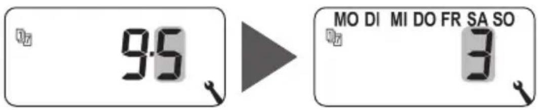
- Then menu 2 opens automatically
or
Open menu 2 if the desired week programme is already active.
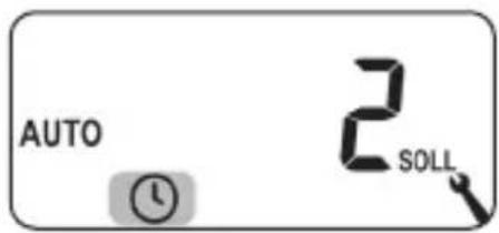
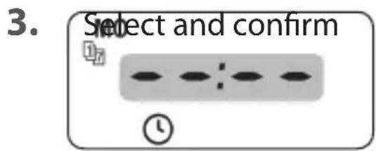

because heating should not be provided on Monday.
-
Repeat point 3 for Tuesday, Wednesday and Thursday.
-
Set and confirm the starting time of the first heating phase for Friday. e.g. 08:00

15.2 Menu 2 - Setting automatic heating phases
EN
- Select and confirm the number of the

desired target temperature for this heating phase, e.g. 1.
- Set and confirm the desired target
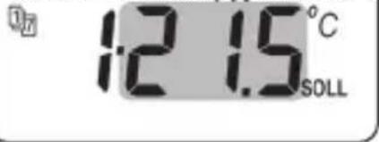
temperature.
e.g. 21.5^ C
- Set and confirm the starting time of the second heating phase for Friday.
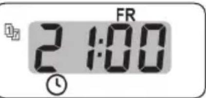
e.g. 21:00
- Select and confirm the number of the
Select and confirm the number of the desired target temperature for this heating phase, e.g. 2.
- Set and confirm the desired target temperature.
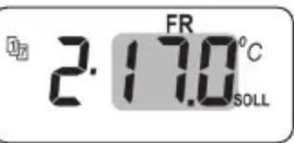
e.g. 17.0^ C
- SA Repeat points 5 to 10.
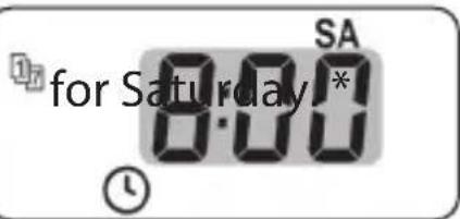
* If the same target temperatures are selected for this, they can no longer be changed.

15.2 Menu 2 - Setting automatic heating phases
EN
12.
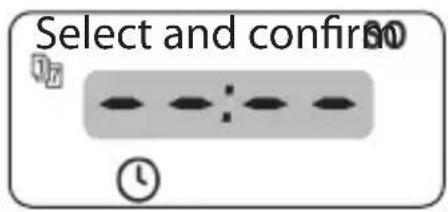
because heating should not be provided on Sunday.
13.
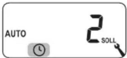
Subsequently the main menu is displayed
or
Menu 9.5.
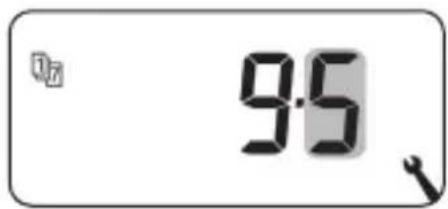
Target temperatures are configured and assigned in the installation wizard and in menu 2 "Setting automatic heating phases".

If the same target temperatures are used in different heating phases, they can only be changed centrally in menu 3.
Information about setting the target temperatures
◆Four target temperatures are available that can be set centrally
◆Each target temperature can be randomly used, e.g. as a comfort or setback temperature.
◆Central changes to a target temperature affect all automatic heating phases that use this target temperature
◆The target temperatures can also be changed with the HomePilot® through the advanced settings of the actuator
SOLL 15.3 Menu 3 - Setting target temperatures centrally
EN
Setting target temperatures centrally
1. Open menu 3.
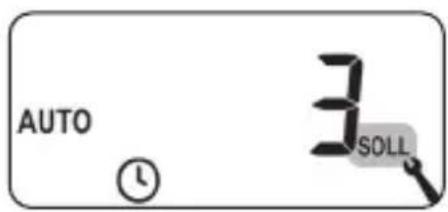
2.
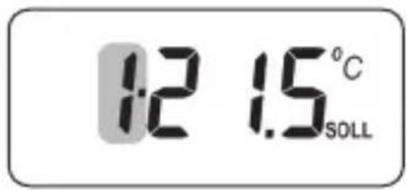
Select and confirm the number of the target temperature to be changed.
3.
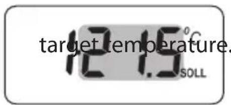
Change and confirm the
Setting range = 4.0 °C to 40 °C
- Repeat points 1 to 3 if you want to change other target temperatures.
This menu enables you to configure additional devices and system settings to customise the DuoFern Room Thermostat 2 to your individual preferences.
The DuoFern settings in menu 9.9 are introduced and described separately from page 103 onwards.
Menu 9 - System settings
| Symbol | Menu | Page |
| SET | 9.1 | Time and date .....78 |
| 9.5 | Week programme .....79 | |
| 9.7 | Installer settings .....81 | |
| 9.8 | Device settings .....93 | |
| 9.9 | DuoFern settings .....103 |
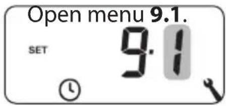
SET 16.1 Menu 9.1 - Setting the time and date
1.
Configure and confirm the desired settings.
Setting order:
2.
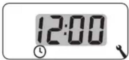
Time
3.
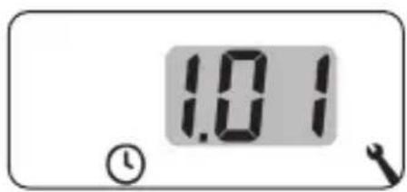
Date
Day.Month
4.
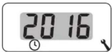
Year
2000 to 2099
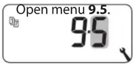
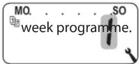
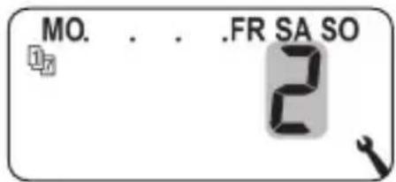
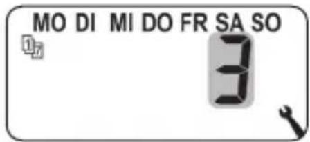
You can adapt the automatic heating phases individually to the weekly profile using the week programmes.
There are three week programmes available:
[1] Weekly switching times (factory setting)
The switching times of the automatic heating phases apply from (Mon .... Sun) [MO .... SO].
[2] Working day and weekend switching times
Separate switching times for (Mon .... Fri) [MO .... FR] and (Sat + Sun) [SA + SO].
[3] Individual day switching times
The switching times of the automatic heating phases can be set for each individual weekday.
![RADEMACHER DuoFern 9485 - [3] Individual day switching times - 1](/content/2026/05/870226/images/b1c5aa18bc677924b8e7fe430c32024c245ec7455ecd3539d37fcc9b66736160.jpg)
Once a week programme has been selected and confirmed, menu 2 opens automatically to set the heating phases.
1.
2.
Select and confirm the desired
- Menu 2 opens automatically to set the heating phases after selecting a week programme, see page 61.
The settings in menu 9.7 must be checked and adapted to the existing heating installation after completing the installation wizard.
Menu 9.7 - Installer settings
| Symbol | Menu | Page |
| 9.7.1 | Heating mode......82 | |
| OFFSET | 9.7.2 | Sensor offset......86 |
| H | 9.7.3 | Hysteresis and minimum on-time......87 |
| 9.7.4 | Valve protection......88 | |
| ▼ | 9.7.5 | Frost protection......89 |
| 9.7.6 | Valve mode......90 | |
| SENSOR | 9.7.7 | Sensor test......92 |
You can set the DuoFern Room Thermostat 2 for one of the following heating modes.
There are three heating modes available:
[1] Room temperature controller (factory setting)
The heating is switched on when the room temperature drops below the set target temperature.
[2] Room temperature controller with limiter
This function can be used for floor heating with particularly sensitive floor coverings. Excessive cooling of the floor can also be prevented with additional heat sources (e.g. fireplace) by defining a minimum floor temperature. It is absolutely essential to connect the device to the external Remote Sensor 9485-F for this heating mode.
The heating is switched on when the room temperature drops below the set target temperature. The room temperature is measured with the internal sensor.
The floor temperature is measured by the external Remote Sensor 9485-F regardless of the room temperature. The set minimum and maximum floor temperature is taken into account in the heating control and limited accordingly.
[3] Cooling function
The air conditioning is switched on when the room temperature exceeds the set target temperature.
![RADEMACHER DuoFern 9485 - [3] Cooling function - 1](/content/2026/05/870226/images/4c2049ff8584f39682ffb16e3b279aee3346a0290099ffd091422a4e8554ba15.jpg)
Additional parameters must be set in each heating mode.
i
16.4 Menu 9.7.1 - Setting the heating mode
EN
1.
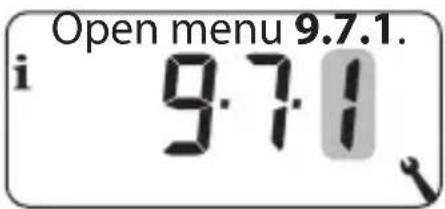
- Continue with the desired heating mode.
2.1 Heating mode [1] - Setting the room temperature controller.
2.2
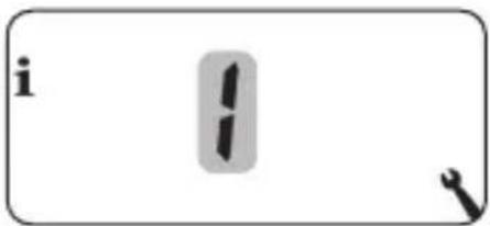
Select and confirm the heating mode [1].
2.3
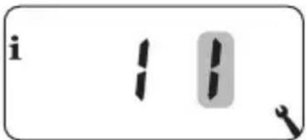
Select and confirm the internal [I] or external [E] temperature sensor.
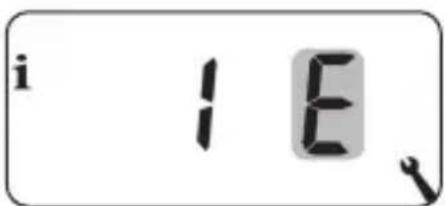

16.4 Menu 9.7.1 - Setting the heating mode
EN
2.1 Heating mode [2] - Setting the room temperature controller with limiter.
2.2
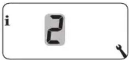
Select and confirm the heating mode [2].
2.3
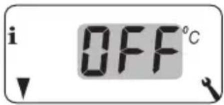
Set and confirm the limiting value for the minimum floor temperature.
Setting range = 10°C to 30°C Factory setting = OFF
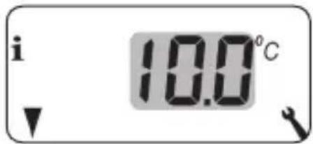
The setting is undertaken in steps of 1.0^ C.
2.4
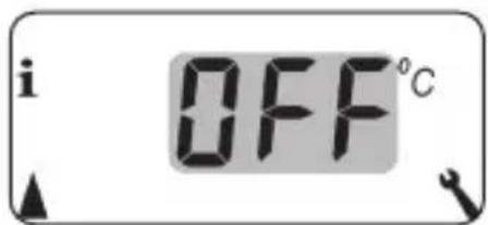
Set and confirm the limiting value for the maximum floor temperature.
Setting range = 20°C to 40°C Factory setting = 35°C
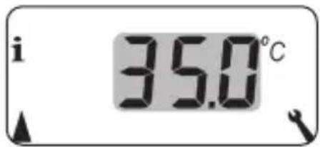
The setting is undertaken in steps of 1.0^ C .

If both a minimum and maximum temperature limit are set, the limiting values must be at least 5 °C apart.
◆An incorrect setting is automatically corrected by the controller.

16.4 Menu 9.7.1 - Setting the heating mode
EN
2.1 Heating mode [3] - Setting the cooling function.
2.2
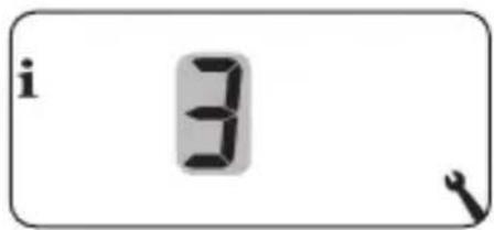
Select and confirm the heating mode [3].
2.3
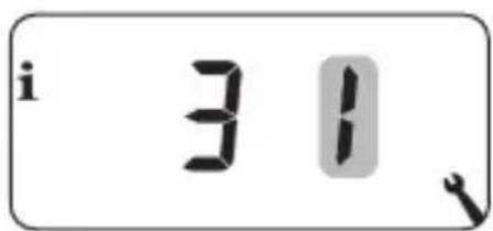
Select and confirm the internal [I] or external [E] temperature sensor.
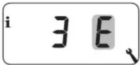
The temperature measured on site can vary from the room temperature if the DuoFern Room Thermostat 2 is installed in a unfavourable position (e.g. behind a curtain or on a cool exterior wall).
Setting range
An adjustment of the measurement in the range of -5^ to +5^ can be carried out using the sensor offset. The setting is undertaken in steps of 0.1^ .
1.
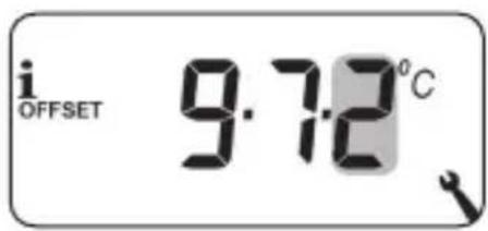
Open menu 9.7.2.
2.
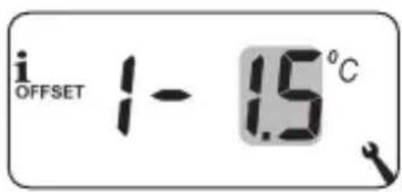
Set the offset for the internal temperature sensor.
e.g. -1.5 °C
3.
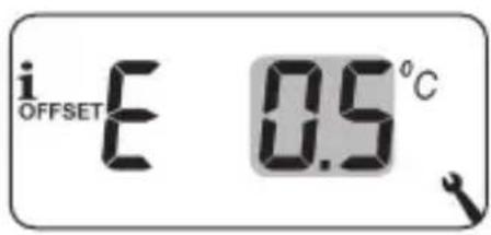
Set the offset for the external temperature sensor.
e.g. 0.5^ C
H
16.6 Menu 9.7.3 - Setting the hysteresis / minimum on-time
EN
This function prevents an unnecessary large number of switching operations by setting a minimum on-time for the relay. This prevents the DuoFern Room Thermostat 2 tripping too often if the room temperatures fluctuate.
1.
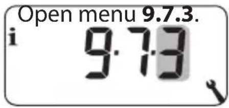
2.
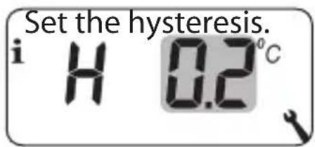
Setting range = 0.1°C to 5°C
Factory setting = 0.2°C
3.
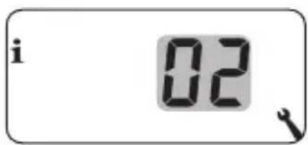
Set the minimum on-time.
Setting range = 1 minute to 10 minutes
Factory setting = 2
i
16.7 Menu 9.7.4 - Setting the valve protection
EN
If an electrothermal control valve (e.g. for floor heating) is not activated for a longer period of time (e.g. in summer), it may get stuck.
Prevent the control valve getting stuck with the "Valve protection" function.
The valve is switched on for a set time at 10:00 if it has not been activated for longer than 3 days (>72 hours).
1.
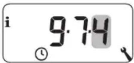
Open menu 9.7.4.
2.
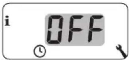
Switch on the valve protection.
On = Valve protection on
OFF = Valve protection off
3.
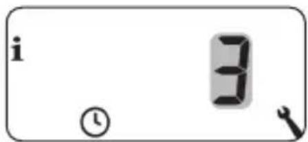
Set the minimum on-time.
e.g. 3 minutes
The "Frost protection" function switches the heating on when the minimum temperature has been reached. The function is independent of the set target temperatures.
1.
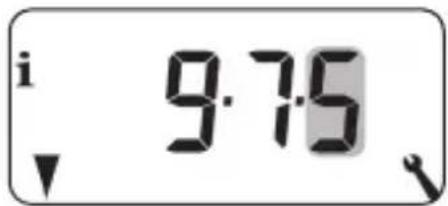
Open menu 9.7.5.
2.
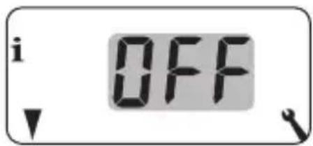
Switch on the frost protection.
$$ \text { On } = \text { Frost protection on } * $$
$$ O F F = \text { Frost protection off } $$
3.
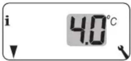
Set the minimum temperature at which the heating is switched on.
$$ e. g. 4. 0 ^ {\circ} C * $$
$$ \text { Factory setting } = \mathrm{On}; 4. 0 ^ {\circ} \mathrm{C} $$
$$ \text { Setting range } = 2. 0 ^ {\circ} \mathrm{C} - 1 0 ^ {\circ} \mathrm{C} $$
Electrothermal valves with the switching states "normally closed (NC)" or "normally open (NO)" are often used for heating control. You can set the respective valve mode in menu 9.7.6 to adapt to the control valve used in each case:
[ NC ] Valve mode normally closed
The control valve remains closed in an isolated, de-energised state.
[ NO ] Valve mode normally open
The control valve remains open in an isolated, de-energised state.
![RADEMACHER DuoFern 9485 - [ NO ] Valve mode normally open - 1](/content/2026/05/870226/images/f899ca0cdcb15d831c8d8e96e467d62ec951ceaae5135b07e0ff2f5d07d4142e.jpg)
The set valve mode also applies to DuoFern actuators connected via radio.
i
16.9 Menu 9.7.6 - Setting the valve mode
EN
1.
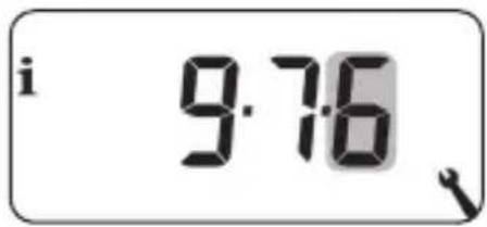
Open menu 9.7.6.
2.
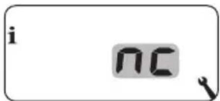
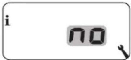
Switch on the valve protection.
$$ \mathrm{nc} = \text { normally closed } $$
$$ \mathrm{no} = \text { normally open } $$
Switch off the relay if the control valve is regulated by a Duofern actuator.
If the control valve is regulated solely by a DuoFern actuator or the DuoFern Room Thermostat 2 only controls radiator actuators, you can switch off the relay to avoid annoying switching noises.

5 sec. Press the minus button for 5 seconds switch the relay off.
Display when the relay is switched off: - no or - nc
5 sec. Press the plus button for 5 seconds switch the relay on.
It is possible to view the readings of the temperature sensors (internal and external) to check the installation.
1.
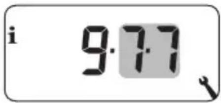
Open menu 9.7.7.
2.
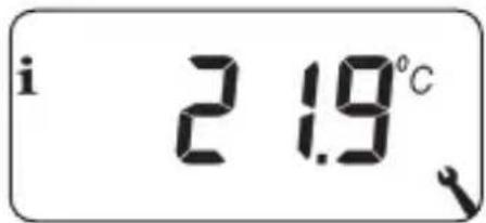
Select and display the desired temperature sensor.
Example: The internal temperature sensor measures 21.9 °C.
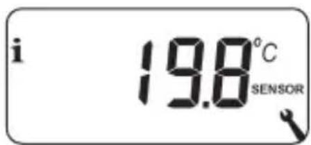
Example:
The external Remote Sensor 9485-F measures 19.8 °C.
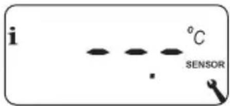
Example:
The external Remote Sensor 9485-F is incorrect or not connected.
Menu 9.8 - Device settings
| Symbol | Menu | Page |
| 9.8.1 | Automatic summer / winter changeover......94 | |
| 9.8.3 | Display lighting ......95 | |
| 9.8.5 | Button lock ......96 | |
| 9.8.6 | Holiday mode ......98 | |
| 9.8.7 | Party mode ......100 | |
| 9.8.0 | Software version ......102 |
The DuoFern Room Thermostat 2 features an automatic summer/winter changeover function.
Summer time
The timer is changed to summer time on the last Sunday in March. The timer is set back one hour at 02:00.
Winter time
The timer is changed to winter time (standard time) on the last Sunday in October. The timer is set back one hour at 03:00.
Recommendation for operating the device outside Germany
If the DuoFern Room Thermostat 2 is not being used in Germany, it may be necessary to switch off the automatic summer/winter changeover function.
1.
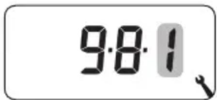
Open menu 9.8.1.
2.
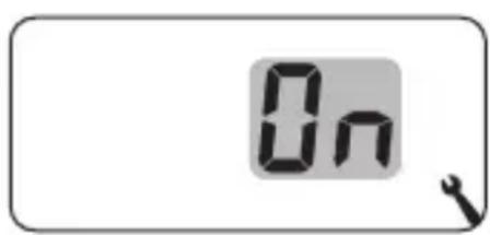
Switch the summer/winter changeover function on/off and confirm.
$$ \mathbf {O F F} = \text { Function off } $$
$$ \mathbf {O n} = \text { Function on } $$
Pressing one of the operating buttons switches the background lighting on the display on and off after a predetermined time.
◆After 10 seconds on the standard display
◆After approx. 1 minute in the menus
You can set the desired brightness level if the background lighting should remain permanently lit up in an idle state (without pressing a button).
1.
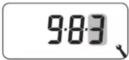
Open menu 9.8.3.
2.
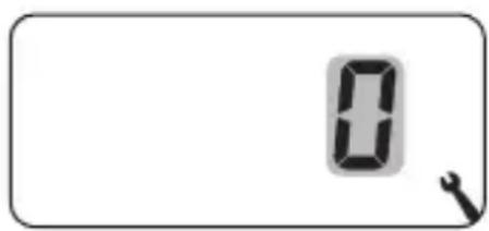
Set and confirm the desired brightness levels.
0 = Switch off the permanent display lighting
1 = Weak brightness
2 = Average brightness
3 = Maximum brightness

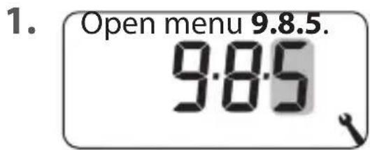
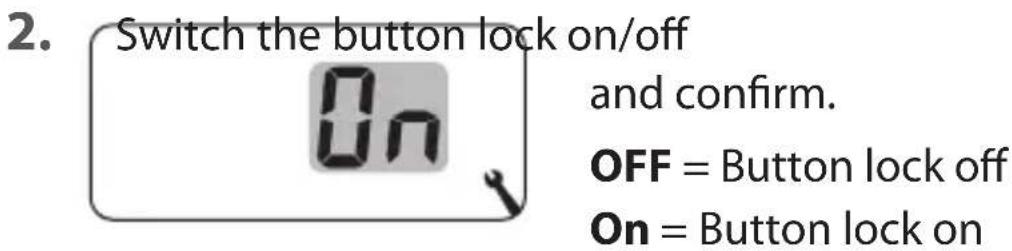
17.3 Menu 9.8.5 - Switching the button lock on/off
EN
You can activate the automatic button lock to protect against any unintentional input.
Automatic activation after approx. two minutes
If the button lock is activated and no buttons are pressed within a period of two minutes, the button lock is switched on automatically.
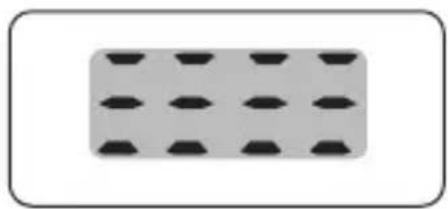
If an attempt is made to call up the menu when the button lock is active, the display flashes.
natural_image
Simple diagram of a rectangular block with evenly spaced black diamond-shaped cells on a gray background (no text or symbols)The button lock is deactivated manually on the standard display

4 sec. Press and hold for 4 seconds.
The button lock is activated manually on the standard display before the time limit expires

4 sec. Press and hold for 4 seconds if you want to activate the automatic button lock before the two minutes expire.

Manual operation of the DuoFern Room Thermostat 2 is also possible when the button lock is active.

17.4 Menu 9.8.6 - Setting the holiday mode incl. the setback temperature
EN
You can switch on a holiday mode and set the desired setback temperature on the DuoFern Room Thermostat 2. The holiday mode can then be directly activated on the standard display.
The heating is regulated to the setback temperature when the holiday mode is activated.
-
Open menu 9.8.6.
-
Switch the holiday mode on/off and confirm. OFF = Holiday mode off On = Holiday mode on
-
Set and confirm the setback temperature. e.g. 17.0 °C
Activating the setback temperature temporarily on the standard display
- 1 sec. Press and hold for 1 second to temporarily activate the setback temperature.
The heating is regulated to the setback temperature until the next automatic heating phase becomes active.
Manual mode

The hand symbol is shown if you press the button briefly.
Activating the setback temperature permanently on the standard display (holiday mode)
4 sec. Press and hold for 4 seconds
to permanently activate the setback temperature (holiday mode). The automatic heating phases have been deactivated.
Automatic mode off

The clock symbol disappears when you press and hold the button.

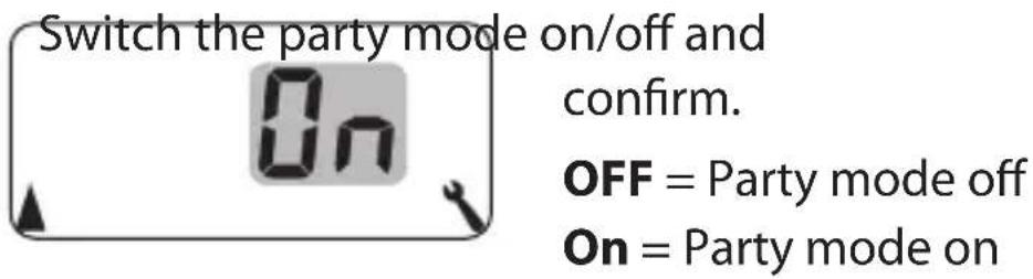
17.5 Menu 9.8.7 - Setting the party mode incl. the comfort temperature
EN
You can switch on a party mode and set the desired comfort temperature on the DuoFern Room Thermostat 2. The party mode can then be directly activated on the standard display.
The heating is regulated to the comfort temperature when the party mode is activated.
1.
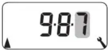
Open menu 9.8.7.
2.
3.
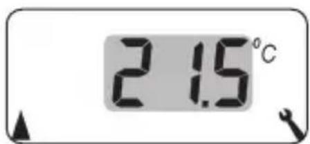
Set and confirm the comfort temperature.
e.g. 21.5^ C
Activating the party mode temporarily on the standard display
+ 1 sec. Press and hold for 1 second to temporarily activate the party mode. The heating is regulated to the comfort temperature until the next automatic heating phase becomes active.
Manual mode

The hand symbol is shown if you press the button briefly.
Activating the party mode permanently on the standard display
4 sec. Press and hold for 4 seconds to permanently activate the party mode. The automatic heating phases have been deactivated for this.
Automatic mode off

The clock symbol disappears when you press and hold the button.

17.6 Menu 9.8.0 - Displaying the software version
EN
This menu enables the current software version of the DuoFern Room Thermostat 2 to be displayed.
1.
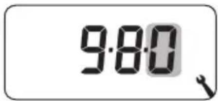
Open menu 9.8.0.
2.
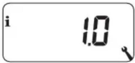
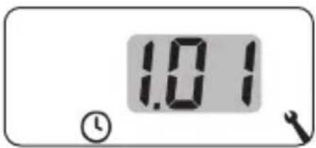
Subsequently the current software version is displayed.
3.
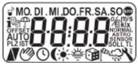

Carry out a display test.
4.

Back to the menu 9.8 Device settings.
In order for your DuoFern Room Thermostat 2 to receive and send control signals in the DuoFern network, it is necessary to log any desired DuoFern device (e.g. DuoFern actuator etc.) on to the DuoFern Room Thermostat 2.

To do so, please also read the operating manual of the respective DuoFern device.
Maximum number of connected devices
You can log a maximum of 20 DuoFern devices on to a DuoFern Room Thermostat 2.
Additional information about logging on can be obtained from the login matrix on our website at:
www.rademacher.de
Menu 9.9 - DuoFern settings
| Symbol | Menu | Page |
| 9.9.1 | Logging on and off...... 104 | |
| 9.9.2 | Setting the DuoFern mode ...... 108 | |
| 9.9.3 | Setting the transmission channel ...... 110 | |
| i I | 9.9.4 | Switching the weather data on/off ...... 111 |
| i IST | 9.9.5 | Displaying the DuoFern address (radio code) .... 113 |

18.1 Menu 9.9.1 - Logging DuoFern devices on/off
EN
1.
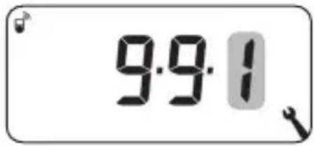
Open menu 9.9.1.
2.
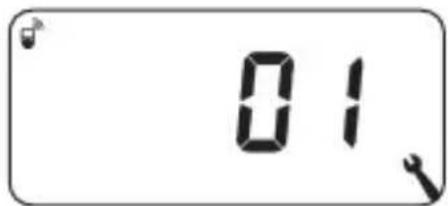
The number of DuoFern devices logged on is displayed.
For example, one device is logged on here.
3. Logging on DuoFern devices.
3.1
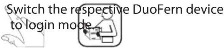
3.2
Start the login procedure.
3.3
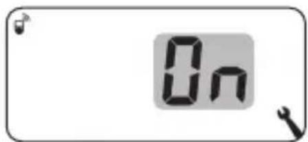
The display flashes [On].
3.4

3.5 Log on the next DuoFern device
or
Back to the menu selection.

18.1 Menu 9.9.1 - Logging DuoFern devices on/off
EN
4. Logging off DuoFern devices.
4.1
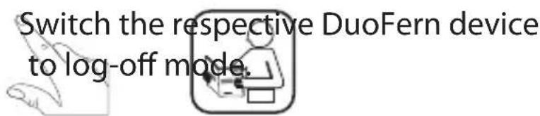
4.2
Start the log-off procedure.
4.3
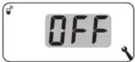
The display flashes [OFF].
4.4
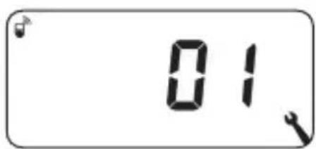
The new number of logged-on devices is displayed after a successful log-off.
4.5 Log off the next DuoFern device
or
Back to the menu selection.
Deleting all connections to the logged-on DuoFern devices
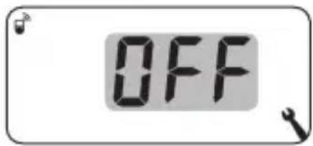
- 4 sec. Press and hold the set button for 4 seconds.
- The display flashes [OFF].
The display flashes [OFF].
- Subsequently all of the connections
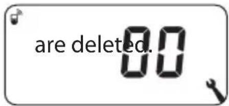

Deleting the connections can lead to problems for the participants, whereby the DuoFern Room Thermostat 2 is still logged on after the deletion process.
◆Always use the "Log-off" function to terminate the connection with other DuoFern devices.
Clearing up the DuoFern network
This function enables you to log off all DuoFern devices from the DuoFern Room Thermostat 2 that are no longer accessible via radio.

All battery-operated DuoFern transmitters (e.g. the DuoFern manual central operating unit) cannot be logged off using this function.
1.
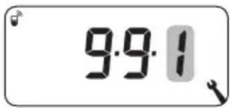
Open menu 9.9.1.
2.
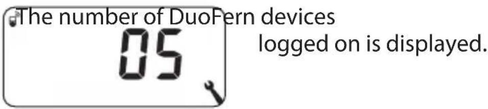
3.

Activate the clear up function.
In order to do this, press and hold the SET button for approx. 4 seconds.
4.
The display flashes.
4.1
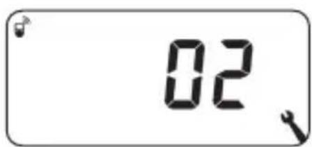
The current number of DuoFern devices logged on (e.g. 2) is displayed after a successful clear up.
The DuoFern Room Thermostat 2 features two DuoFern modes that enable you to specify how the it behaves within the DuoFern network or in the local installation on site.
Setting heating phases centrally in the HomePilot® or locally in the DuoFern Room Thermostat 2
[1] DuoFern receiver
◆Heating phases are controlled centrally (e.g. through scenes), for example, by the HomePilot®
◆No local heating phases can be set and activated in this mode
[3] Local operation (factory setting)
◆The heating phases set in the DuoFern Room Thermostat 9485 are stored locally
◆In addition, control commands can also be received and executed from the DuoFern network (e.g. from a DuoFern manual transmitter)
![RADEMACHER DuoFern 9485 - [3] Local operation (factory setting) - 1](/content/2026/05/870226/images/b12d6f3ea554de27aa84cfa3d1cde8fd0906e7fb689fbf0f044fbd61b02a1f82.jpg)
All manual and automatic control signals received via radio are executed on site regardless of the set mode.
![RADEMACHER DuoFern 9485 - [3] Local operation (factory setting) - 2](/content/2026/05/870226/images/ced89a1df9d97224dcd74d1741575b3ae631c6defff90a4b92ed2327f7706a4b.jpg)
18.2 Menu 9.9.2 - Setting the DuoFern mode
EN
1.
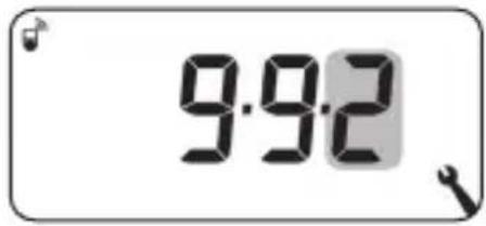
Open menu 9.9.2.
2.
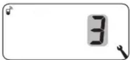
Set and confirm the desired DuoFern mode.
1 = DuoFern receiver
3 = Local operation
If a DuoFern actuator is logged on to the DuoFern Thermostat 9485 via radio, a control valve can be regulated by this. Direct cabling between the DuoFern Room Thermostat 2 and the control valve is not required.
If a multi-channel DuoFern actuator is used for this, the channel that is used must be set on the DuoFern Room Thermostat 2.

Pay attention when wiring the DuoFern actuator to the control valve to the channel used and check that the control valve actually also controls the control commands of the DuoFern Room Thermostat 2.
1.
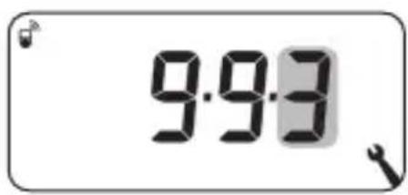
Open menu 9.9.3.
2.
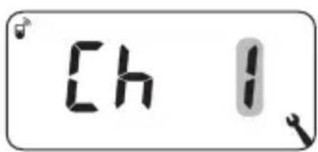
Set and confirm the transmission channel.
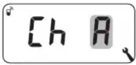
1 = Channel 1
2 = Channel 2
A = All channels
The DuoFern Room Thermostat 2 can receive and display weather data (temperature, brightness, wind velocity and rain) from a DuoFern Environmental Sensor. It is not necessary to log the DuoFern Environmental Sensor on to the DuoFern Room Thermostat 2.
The weather data can be called up and displayed directly on the standard display, see page 55.
Maximum number of environmental sensors
◆A maximum of 4 environmental sensors are detected
◆Only one sensor can ever be selected as the source
Observing delays in displaying the weather data

Environmental sensors update the weather data approx. every 5 minutes and therefore it can take a few minutes for the weather data to be displayed after the settings are configured.
◆This also applies after a power failure.
◆If no new weather data is received for 45 minutes, this is no longer available.

18.4 Menu 9.9.4 - Switching the weather data on/off
EN
1.
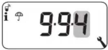
Open menu 9.9.4.
2.
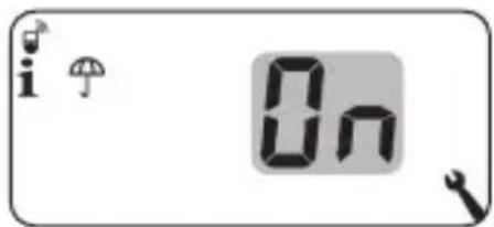
Switch the weather data display on/off and confirm.
$$ \mathbf {O F F} = \mathbf {O f f} $$
$$ \mathbf {O n} = \mathbf {O n} $$
3.
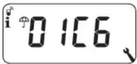
The last four digits of the DuoFern address (radio code) of the current environmental sensor are displayed.

Display if no environmental sensor has been received or is in radio range so far.
4.
Select and confirm the desired environmental sensor.
Deleting all detected environmental sensors

Briefly press the SET button.
All environmental sensors are deleted.
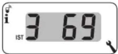
Each DuoFern device has an address (radio code) via which it communicates on the DuoFern network. If necessary, you can display the DuoFern address of the DuoFern Room Thermostat 2.
1.
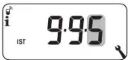
Open menu 9.9.5.
2.
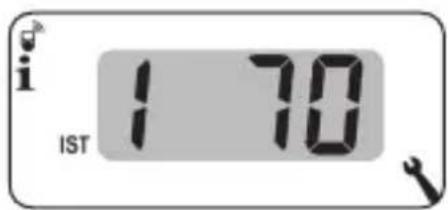
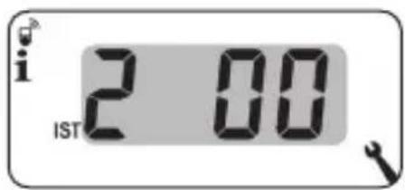
Two digits of the six-digit address are always shown in the form of scroll text, see example.
3.
M or OK
Back to the menu selection.
Information on logging on to HomePilot ^® as well as details on configuration and application examples can be found in the Service Center on our website at:
service.rademacher.de
or by using the following QR code:


20. Deleting all settings, software reset
EN
A software reset can be carried out to reset the DuoFern Room Thermostat 2 to the original default condition as when supplied.

All settings in menu "9.7 Installer settings" are also lost in the process.
◆Make sure that you note all settings in menu 9.7 before carrying out a software reset and check these after the reset.
- M + A+ V OK Press and hold the four buttons simultaneously for five seconds until all of the symbols are shown on the display.
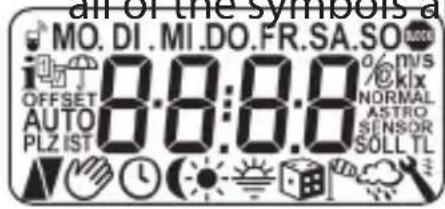
- The software version is then shown for five seconds.
All settings are deleted and reset to the default factory settings.
- Start with the settings as specified from page 49 onwards (installation wizard).

The DuoFern connection data is retained after a software reset. You can log off or delete DuoFern devices in menu 9.9.1, see page 104.

21. Carrying out a hardware reset
EN
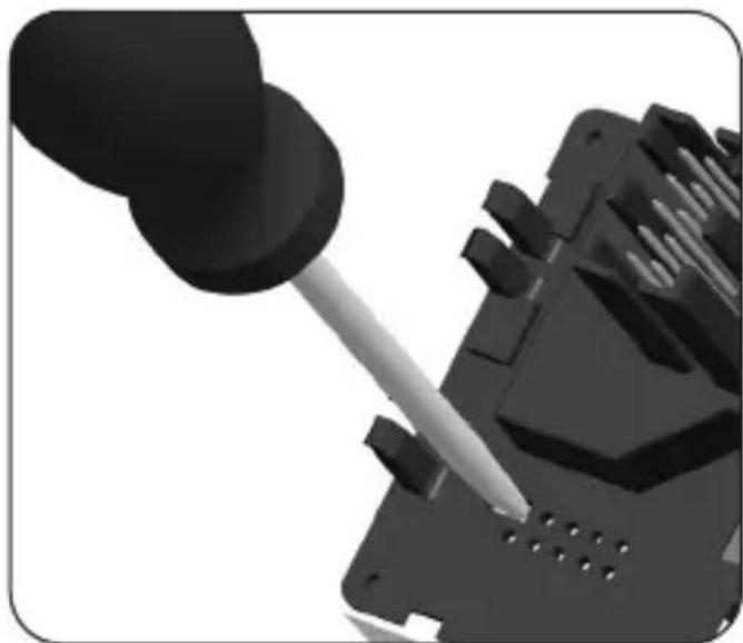
A hardware reset can be carried out in the event that the DuoFern Room Thermostat 2 no longer react to commands.
- To do so, pull the operating unit out of the installation housing.

ATTENTION!
Risk of damage due to the overheating or excessive cooling of the room or flooring.
The relay output remains unchanged if the operating unit is pulled out of the installation housing during operation. Control and limiting functions where appropriate are no longer provided.
◆Make sure that a relay state that poses no risk is set before removing the operating unit.
◆Switch off the central heating or air conditioning beforehand if necessary.
- Two contacts, which must be carefully bridged for a few seconds, for example, with the help of a flat-head screwdriver, are located in the centre of an opening on the rear of the operating unit.
natural_image
Close-up of a black pipette inserted into a mechanical component with a screwdriver inserted (no visible text or symbols)
21. Carrying out a hardware reset
EN
- The operating unit can be reinserted into the installation housing as soon as the screwdriver has been removed from the contacts.
The time and date are lost during a hardware reset. All other settings are retained.

22. Error messages
Error 1
The DuoFern Room Thermostat 2 has an invalid DuoFern address (radio code).
◆Please carry out a hardware reset, see page 116.
◆Check the DuoFern address (radio code) in menu 9.9.5 if the problem persists, see page 113.
- Please then contact the RADEMACHER Service department, see page 124.
Error 2
The DuoFern Room Thermostat 2 has overheated and switched off for safety reasons.
◆It is very likely that a large load has been connected.
◆The maximum permissible connected loads can be found in the technical specifications, see page 34.
◆The error message can only be confirmed by pressing the OK button when the device is no longer overheating.
Error 2

The DuoFern Room Thermostat 2 does not function until the error has been confirmed. The controller is switched off.
Error 3
There is a communication problem.
◆Check that all logged-on actuators and the HomePilot® if necessary are connected properly and are within range.
◆A repeater may be required for larger distances.
Each DuoFern device that is connected to the mains power supply is a repeater (e.g. switch actuator sockets, HomePilot ^® , DuoFern actuators etc).
◆If devices have been logged on that are no longer available (e.g. due to a defect, amongst other things), these can be deleted by the "Clear up" function, see page 107.
◆In the event of a transmission error, the device makes an attempt to reach the DuoFern actuator or the HomePilot® again every 10 minutes.
The error message disappears automatically if this is successful.
Error 4
The temperature sensor provides invalid readings.
◆Carry out a hardware reset, see page 116.
◆If an optional external temperature sensor (Remote Sensor 9485-F) is connected, please check the cabling.
◆Please contact the RADEMACHER Service department if only the internal sensor is used and the problem still persists, see page 124.
◆The readings of the sensors can be checked in menu 9.7.7, see page 92.
◆The controller switches to an emergency mode in the event of a faulty sensor by switching on for 6 minutes (30%) and switching off for 14 minutes (70%). This prevents excessive cooling of the room and overheating of the floor.

DANGER!
There is a risk of fatal electric shock when touching electrical components.
◆Disconnect all phases of the mains power cable and secure it to prevent any reconnection. Check that the system is de-energised.
- Log the DuoFern Room Thermostat 2 off the DuoFern network.
- Switch off the mains power, secure it from restarting and check that the system is de-energised.
- Carefully pull the operating unit out of the installation housing.
- Remove the frame.
- Release the claw fasteners of the installation housing and pull it out of the flush-mounted box.
- Disconnect the connecting cable from the installation housing.
- Secure the connection point against restarting and the connecting cable from unintentional contact.

24. Simplified EU Declaration of Conformity
EN

RADEMACHER Geräte-Elektronik GmbH hereby declares that the DuoFern Room Thermostat 2 complies with the Directive 2014/53/EU (Radio Equipment Directive).
The full text of the declaration of conformity is available at the following website:
natural_image
Coiled black cable with two wires attached, no visible text or symbolsRADEMACHER Geräte-Elektronik GmbH provides a 24-month warranty for new systems that have been installed in compliance with the installation instructions. All construction faults, material defects and manufacturing defects are covered by the warranty.
Your statutory warranty claims remain unaffected by this warranty.
The following are not covered by the warranty:
◆Incorrect fitting or installation
◆Non-observance of the installation and operating instructions
◆Improper operation or wear and tear
◆External influences, such as impacts, knocks or weathering
◆Repairs and modifications by third parties, unauthorised persons
◆Use of unsuitable accessories
◆Damage caused by unacceptable excess voltages (e.g. lightning)
◆Operational malfunctions caused by radio frequency overlapping and other such radio interference
A prerequisite for the warranty is that the new device must have been purchased from one of our approved specialist retailers. Proof of this must be provided by presenting a copy of the invoice.
RADEMACHER will remedy any defects that occur within the warranty period free of charge either by repair or by replacement of the affected parts or by supplying a new replacement unit or one to the same value. There is no general extension of the original warranty period by delivery of a replacement or by repair as per the terms of the warranty.
RADEMACHER
46414 Rhede (Germany)
info@rademacher.de
www.rademacher.de
Service:
Hotline 01807 933-171*
Fax +49 2872 933-253
service@rademacher.de
* 30 seconds free of charge, subsequently 14 cents / minute from German fixed line networks and max. 42 cents / minute from German mobile networks.
- DuoFern Room Thermostat 2
- This manual....5
- Hazard symbols ......6
- Safety instructions....8
- Included in delivery 13
- General view of the operating unit......14
- Product description 22
- Technical specifications 34
- Safety instructions for the electrical connection ..... 39
- Menu 9.8 - Device settings ...... 93
- Menu 9.9 - DuoFern settings....103
- This manual...
- How to use this manual
- Hazard symbols
- Levels of danger and signal words
- DANGER!
- WARNING! WARNING!
- CAUTION!
- ATTENTION!
- Depiction
- Description
- The use of defective equipment can lead to personal injury and damage to property (electric shocks / short circuiting).
- Improper use leads to an increased risk of injury.
- Risk of damage due to the overheating or excessive cooling of the room or flooring.
- Only use original spare parts and accessories from RADEMACHER
- Operating conditions
- Improper use can lead to serious injuries or property damage.
- There is a risk of fatal injury caused by short circuiting and electric shocks if the DuoFern Room Thermostat 2 is used outdoors or in damp rooms.
- Required expert knowledge of the installer
- UW
- DIN 49075
- 2014/53/EU
- ELV
- Electrothermal control valves
- Valve mode NC (normally closed)
- Valve mode NO (normally open)
- Hysteresis / minimum on-time
- Offset (sensor offset)
- Included in delivery
- After unpacking please check and compare...
- Pos. Symbol Description
- Target temperature
- Symbols Description
- Actual temperature
- Time
- Support for three heating modes
- Setting multiple heating phases
- Setting heating phases centrally in the HomePilot® or locally in the DuoFern Room Thermostat 2
- Potential-free relay output
- Connecting an external temperature sensor (optional)
- When is it absolutely essential to use the external Remote Sensor 9485-F?
- Two valve modes (NC/NO) to adapt to the control valve used
- Manual mode
- Installation and electrical connection
- Compatible switch ranges
- Sample application 1
- Home office
- Bathroom
- Living room
- Sample application 2
- There is a risk of an unintentional or erroneous influence through automated scenes or manual operation.
- Sample application 3
- Central control through the HomePilot®
- Sample application 4
- DuoFern Room Thermostat 2 for group control of DuoFern Radiator Actuators 2
- Self-sufficient system
- Control via HomePilot®
- Power reserve (approx. 8 hours)
- Time and date after a power failure
- Data retention following a power failure
- There is a risk of fatal electric shock when touching electrical components.
- There is a risk of fatal injury caused by short circuiting when the DuoFern Room Thermostat 2 is overloaded.
- Only switch extra-low voltage with basic insulation
- Installation materials
- Length of insulation stripped:
- Optional connection of the external Remote Sensor 9485-F
- Absolutely essential use of the external Remote Sensor 9485-F
- Maximum length of lead to connect the external Remote Sensor 9485-F
- Electrical connection
- i
- Introduction to opening the menus and setting the functions
- EN
- Continue with menu 9.7 "Installer settings"
- Readiness for operation
- Initial commissioning with the help of the installation wizard
- Maximum number of daily heating phases
- Pre-setting the week programme
- Assigning different target temperatures
- 6.
- 7.
- 8.
- 9.
- 10.
- 11.
- or
- 12.
- Resetting the manual change
- Switching automatic mode on/off directly on the standard display
- Automatic mode on
- Automatic mode off
- Calling up and displaying weather data
- Symbol depending on the brightness:
- Exiting the weather data display
- Main menu
- Symbol Menu Page
- Standardised menu structure
- AUTO
- Menu 1 - Switching automatic mode on/off
- Automatic mode on (symbol on the standard display)
- Automatic mode off (symbol on the standard display)
- Both symbols on the standard display
- Switching automatic mode on/off in menu 1
- 1.
- 2.
- Toggling directly on the standard display
- Additional information about the setting:
- Example 1 Family programme
- Example 2 Single household
- Example 3 Home office
- Example 1 Setting (family programme)
- Menu 2 - Setting automatic heating phases
- Example 2 Setting (single household)
- 13.
- Setting the heating phases for Saturday / Sunday (SA/SO)
- 14.
- 15.
- 16.
- 17.
- 18.
- 19.
- Example 3 Setting (home office)
- Information about setting the target temperatures
- SOLL 15.3 Menu 3 - Setting target temperatures centrally
- Setting target temperatures centrally
- Open menu 3.
- 3.
- SET 16.1 Menu 9.1 - Setting the time and date
- Setting order:
- 4.
- There are three week programmes available:
- [1] Weekly switching times (factory setting)
- [2] Working day and weekend switching times
- [3] Individual day switching times
- There are three heating modes available:
- [1] Room temperature controller (factory setting)
- [2] Room temperature controller with limiter
- [3] Cooling function
- Menu 9.7.1 - Setting the heating mode
- Heating mode [1] - Setting the room temperature controller.
- 2.2
- 2.3
- Heating mode [2] - Setting the room temperature controller with limiter.
- Setting range = 10°C to 30°C Factory setting = OFF
- Setting range = 20°C to 40°C Factory setting = 35°C
- Heating mode [3] - Setting the cooling function.
- Setting range
- H
- Menu 9.7.3 - Setting the hysteresis / minimum on-time
- Menu 9.7.4 - Setting the valve protection
- [ NC ] Valve mode normally closed
- [ NO ] Valve mode normally open
- Menu 9.7.6 - Setting the valve mode
- Switch off the relay if the control valve is regulated by a Duofern actuator.
- Summer time
- Winter time
- Recommendation for operating the device outside Germany
- Menu 9.8.5 - Switching the button lock on/off
- Automatic activation after approx. two minutes
- The button lock is deactivated manually on the standard display
- The button lock is activated manually on the standard display before the time limit expires
- Menu 9.8.6 - Setting the holiday mode incl. the setback temperature
- Activating the setback temperature temporarily on the standard display
- Activating the setback temperature permanently on the standard display (holiday mode)
- Menu 9.8.7 - Setting the party mode incl. the comfort temperature
- Activating the party mode temporarily on the standard display
- Activating the party mode permanently on the standard display
- Menu 9.8.0 - Displaying the software version
- Maximum number of connected devices
- Menu 9.9.1 - Logging DuoFern devices on/off
- Logging on DuoFern devices.
- Logging off DuoFern devices.
- 4.1
- 4.2
- 4.3
- 4.4
- Log off the next DuoFern device
- Deleting all connections to the logged-on DuoFern devices
- Clearing up the DuoFern network
- [1] DuoFern receiver
- [3] Local operation (factory setting)
- Menu 9.9.2 - Setting the DuoFern mode
- Maximum number of environmental sensors
- Observing delays in displaying the weather data
- Menu 9.9.4 - Switching the weather data on/off
- Deleting all detected environmental sensors
- Deleting all settings, software reset
- Carrying out a hardware reset
- Error messages
- Error 1
- Error 2
- Error 3
- Error 4
- Simplified EU Declaration of Conformity
- The following are not covered by the warranty:
- RADEMACHER
- Service:
Brand : RADEMACHER
Model : DuoFern 9485
Category : Thermostat