PT-AA220 - Receiver PureLink - Free user manual and instructions
Find the device manual for free PT-AA220 PureLink in PDF.


| Product Type | Digital Audio Amplifier (Receiver) |
| Brand | PureLink |
| Model | PT-AA220 |
| Amplifier Class | Class-D |
| Audio Inputs | 2x Stereo Line (RCA, 3.5mm jack); 1x Balanced MIC (3-pin terminal block) |
| Audio Outputs | 1x Amplifier (4-pin terminal block, 4-8Ω); 1x Stereo Line (3.5mm jack) |
| Default Power Output | 2x20W @ 4Ω |
| Bridge Mode Output | 1x40W @ 8Ω |
| Dual-Mono Mode | Yes (sums stereo to mono on both channels) |
| Frequency Response | 20Hz - 20kHz |
| Signal-to-Noise Ratio | 80dB at maximum output |
| THD + Noise | 1% @ 1kHz, 0.3% @ 20kHz at nominal level |
| Stereo Channel Separation | >75dB |
| Common Mode Rejection Ratio | >70dB |
| Voltage Gain | 32dB |
| Input Impedance | >10kΩ |
| Output Impedance (Line) | 50Ω |
| Microphone Phantom Power | 48V (selectable) |
| Control Methods | Front panel buttons, IR remote (optional), RS232 (9600 baud) |
| Noise Gate | Auto-mute when no input signal |
| Cooling | Convection (fanless) |
| Power Supply | External adapter included (model unspecified) |
| Safety Features | Overheat protection, antistatic case |
| Package Contents | 1x PT-AA220, 2x Pluggable Terminal Blocks, 1x Power Adapter, 1x Power Cord, 4x Plastic Cushions, 1x User Manual |
| Warranty | 2 years limited (subject to terms) |
Frequently Asked Questions - PT-AA220 PureLink
User questions about PT-AA220 PureLink
0 question about this device. Answer the ones you know or ask your own.
Ask a new question about this device
Download the instructions for your Receiver in PDF format for free! Find your manual PT-AA220 - PureLink and take your electronic device back in hand. On this page are published all the documents necessary for the use of your device. PT-AA220 by PureLink.
USER MANUAL PT-AA220 PureLink
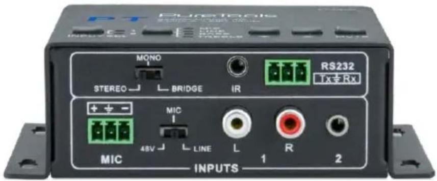
User Manual
Audio Amplifier 2x20W Output, 4Ω, 2 Line & 1 MIC Inputs
Model PT-AA220
Designed in Germany
Preface
Read this user manual carefully before using this product. Pictures shown in this manual are for reference only. Different model layouts and specifications are subject to the physical product.
This manual is for operation instructions only, not for any maintenance usage.
In the constant effort to improve our product, we reserve the right to make changes in functions or parameters without prior notice or obligation.
Trademarks
Product model and logo are trademarks. Any other trademarks mentioned in this manual are acknowledged as the properties of the trademark owner. No part of this publication may be copied or reproduced without the prior written consent.
FCC Statement
This equipment generates, uses and can radiate radio frequency energy and, if not installed and used in accordance with the instructions, may cause harmful interference to radio communications. It has been tested and found to comply with the limits for a Class B digital device, pursuant to part 15 of the FCC Rules. These limits are designed to provide reasonable protection against harmful interference in a commercial installation.
Operation of this equipment in a residential area is likely to cause interference, in which case the user at their own expense will be required to take whatever measures may be necessary to correct the interference.
Any changes or modifications not expressly approved by the manufacture would void the user's authority to operate the equipment.
REACH | 1907/2006/EU
ROHS | 2011/65/EU
PureLink hereby declares that this product PureTools PT-AA220 complies with Directives 1907/2006/EU und 2011/65/EU.
EMC / LVD (Electro Magnetic Compatibility / Low Voltage Directive)
PureLink GmbH hereby declares that this product PureTools PT-AA220 complies with Directives 2014/30/EU and 2014/35/EU. The full text of the EU Declaration of Conformity is available at the following Internet address:
http://www.purelink.de/ce/4251364706633_CE.pdf


SAFETY PRECAUTIONS
To insure the best from the product, please read all instructions carefully before using the device. Save this manual for further reference.
- Unpack the equipment carefully and save the original box and packing material for possible future shipment
- Follow basic safety precautions to reduce the risk of fire, electrical shock and injury to persons.
- Do not dismantle the housing or modify the module. It may result in electrical shock or burn.
- Using supplies or parts not meeting the products' specifications may cause damage, deterioration or malfunction.
- Refer all servicing to qualified service personnel.
- To prevent fire or shock hazard, do not expose the unit to rain, moisture or install this product near water.
- Do not put any heavy items on the extension cable in case of extrusion.
- Do not remove the housing of the device as opening or removing housing may expose you to dangerous voltage or other hazards.
- Install the device in a place with fine ventilation to avoid damage caused by overheat.
- Keep the module away from liquids.
- Spillage into the housing may result in fire, electrical shock, or equipment damage. If an object or liquid falls or spills on to the housing, unplug the module immediately.
- Do not twist or pull by force ends of the optical cable. It can cause malfunction.
- Do not use liquid or aerosol cleaners to clean this unit. Always unplug the power to the device before cleaning.
- Unplug the power cord when left unused for a long period of time.
- Information on disposal for scrapped devices: do not burn or mix with general household waste, please treat them as normal electrical wastes.
Contents
1. Introduction....1
1.1. Introduction to PT-AA220....1
1.2. Feature .... 1
1.3. Package List 2
2. System Connection....3
3. System Operation....7
3.1. Panel Control....7
3.1.1. Audio Switching....7
3.1.2. Volume/EQ Control 8
3.2. IR Remote Control....9
3.3.RS232 Command 10
4. Specification.... 12
- Panel Drawing.... 13
- Troubleshooting & Maintenance.... 14
- After-Sales Service.... 15
1. Introduction
1.1. Introduction to PT-AA220
The PT-AA220 is a compact-size digital amplifier (Class-D) with 3 inputs (2 line in and 1 balanced MIC). It is integrated with powerful functions, including bridge connection, dual-mono, EQ control, microphone mixer etc.
It has a good application in different places, including classroom, small meeting room, lecture hall, bar, pub etc.
1.2. Feature
- 2x20Watt@4Ohm as the default amplifier output.
- Bridge connection function. User can switch the PT-AA220 to be 1x40Watt@8Ohm by bridge connection.
- Two stereo audio inputs, switchable by button, IR remote & RS232.
- Volume/Bass/Treble controllable by buttons IR remote & RS232.
- MIC port can support balance/unbalance signal, suppress the external noise effectively.
- Line audio output at 3.5mm jack, with volume controllable.
- Dual-mono function. User can sum up the stereo audio to two times mono audio.
- MIC mixer function. The microphone will be mixed to the line audio output, and be controlled separately.
- MIC input supports 48V phantom power, dynamic MIC and wireless MIC.
- Auto noise gate. It keeps detecting the audio and MIC input, will mute the output when there is no input.
- Ultra low inrush current, no need for power sequencing. This allows multiple PT-AA220 to be powered on simultaneously without overloading power circuits.
- Convection cooler, fan is not needed.
- Antistatic case design: providing good protection for long-term and stable performance.
1.3. Package List
- 1 x PT-AA220 (The mounting ears and PT-AA220 are as a whole.)
- 2 x Pluggable Terminal Blocks
- 1 x Power Adapter
- 1 x Power Cord
- 4 x Plastic Cushions
- 1 x User Manual
Note:
- The IR remote and its battery are offered for charge separately.
- The IR receiver is also offered for charge.
- Please confirm if the product and the accessories are all included, if not, please contact with the dealers.
2. System Connection
2.1. Audio Output
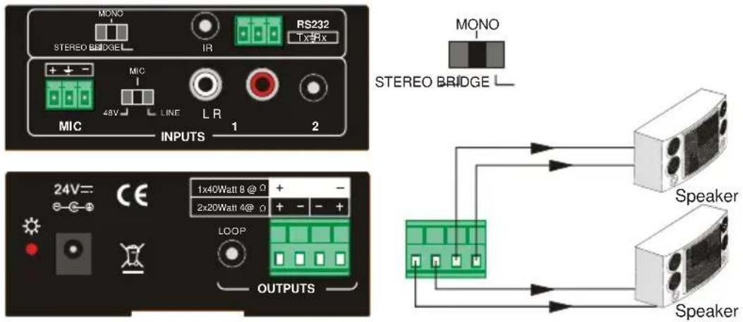
2.1.1. Default Output: 2x20Watt@4Ohm
The default output of amplifier is 2x20Watt@40hm, so user can connect the amplifier output in the regular way. As the picture below:
2.1.2. Bridge Connection: 1x40Watt@8Ohm
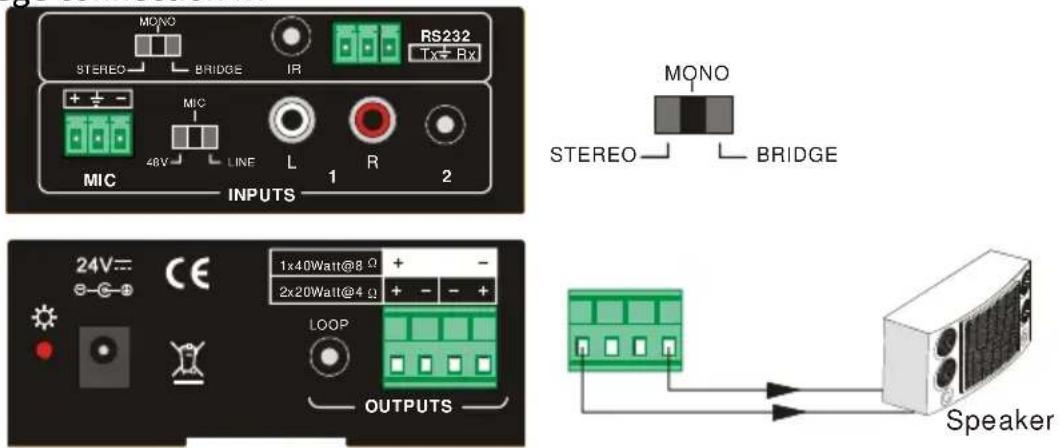
The PT-AA220 has the bridge connection, to double the output power at 1x40Watt@8Ohm. It will sum up the input left channel and input right channel to be mono output, and the power is up to 40Watt.
The bridge connection is:
2.1.3. Dual-Mono Output
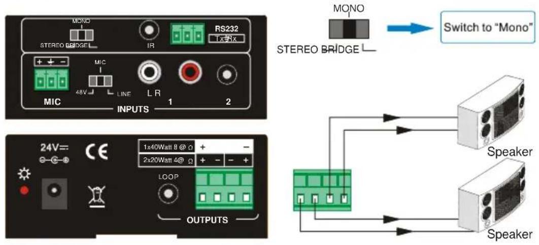
The PT-AA220 also has the function of double-mono output. It can sum up the left and right channel, to be the mono audio output. In this way, the both of the outputs are showing the same mono audio.
The connection is:
2.2. Microphone Input
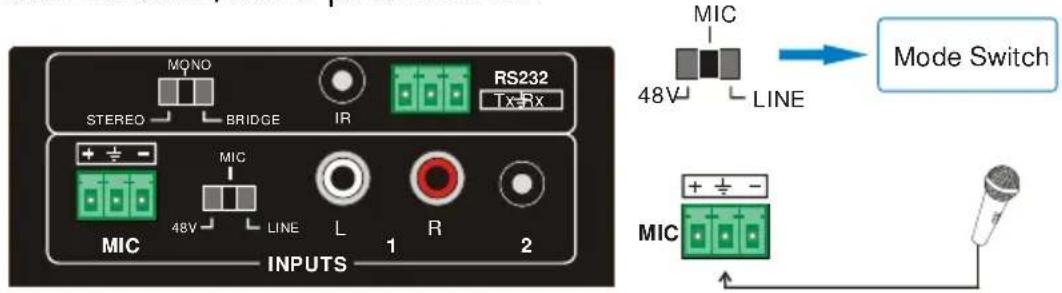
The microphone input of PT-AA220 has three modes, and different modes use different connections, as the picture below:
2.2.1. 48V Phantom Power Input
When the switch turns to "48V", the MIC input will provide a 48V phantom power. This is usually used for power supply for condenser microphone, Connection is: "+" connects to positive, "-" connects to negative and "─" to ground.
Note: In this mode, only condenser microphone can be connected with.
2.2.2. MIC Input
When the switch turns to "MIC", the microphone input is used for connecting with dynamic microphone. There are two different connections:
1) Unbalanced connection:
“⊥” connects to ground, and “-” connects to signal.
“⊥” connects to ground, and “+” connects to signal.
2) Balanced connection: "+" connects to positive, "-" connects to negative and "⊥" connects to ground.
2.2.3. LINE Input
When the switch turns to "LINE", the microphone input is used for connecting with normal audio or wireless microphone output. There are two different connections:
1) Unbalanced connection:
“⊥” connects to ground, and “-” connects to signal.
“⊥” connects to ground, and “+” connects to signal.
2) Balanced connection: "+" connects to positive, "-" connects to negative and " ± " connects to ground.
2.3. System Diagram
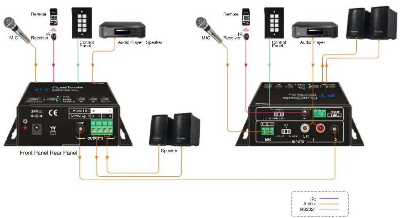
flowchart
graph TD
    A["Front Panel Rear Panel"] --> B["PT DuneThesis"]
    B --> C["Microphones: MIC, Receiver, IR"]
    C --> D["Control Panel"]
    D --> E["Audio Player Speaker"]
    E --> F["Speaker"]
    F --> G["Control Panel"]
    G --> H["Audio Player"]
    H --> I["Microphones: MIC, Receiver, IR"]
    I --> J["Control Panel"]
    J --> K["Audio Player"]
    K --> L["Microphones: MIC, Receiver, IR"]
    L --> M["Control Panel"]
    M --> N["Audio Player"]
    N --> O["Microphones: MIC, Receiver, IR"]
    O --> P["Control Panel"]
    P --> Q["Audio Player"]
    Q --> R["Microphones: MIC, Receiver, IR"]
    R --> S["Control Panel"]
    S --> T["Audio Player"]
    T --> U["Microphones: MIC, Receiver, IR"]
    U --> V["Control Panel"]
    V --> W["Audio Player"]
    W --> X["Microphones: MIC, Receiver, IR"]
3. System Operation
3.1. Panel Control
The buttons provides the control of volume/EQ control and switching. The following content introduces audio switching and EQ control in detail.
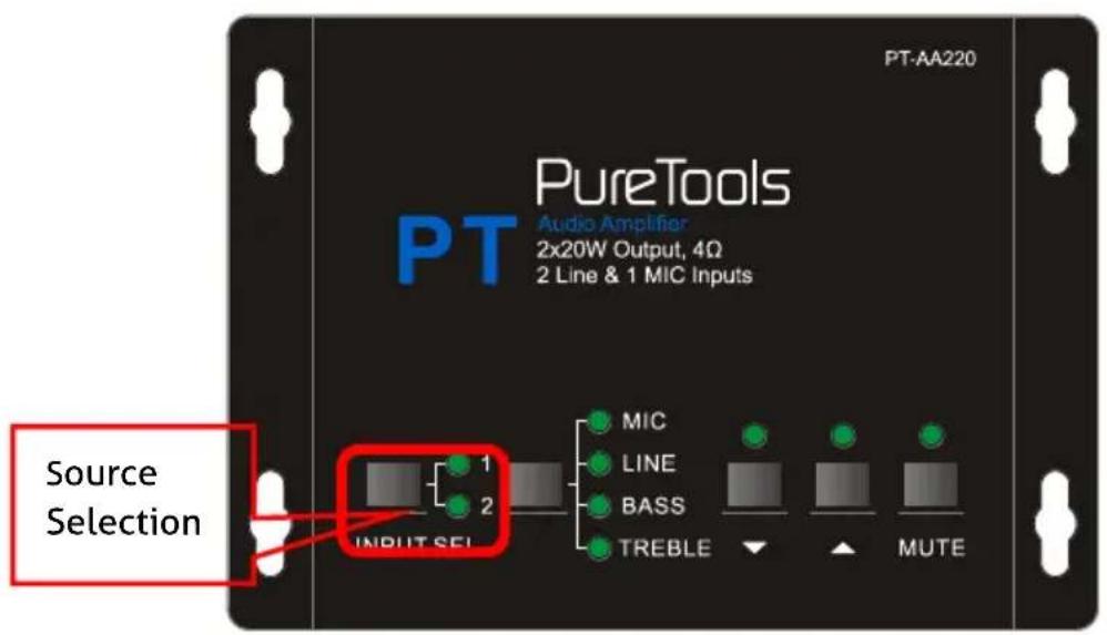
3.1.1. Audio Switching
There are two switchable stereo audio inputs, one 2xRCA input, and one 3.5mm jack input, switchable through the buttons as below:
3.1.2. Volume/EQ Control
The line volume and MIC volume can be controlled by the buttons.
The MIC Volume/LINE volume/LINE bass/LINE treble will be selected by the buttons, and controlled up/down/mute by the function buttons. Please check the picture below:
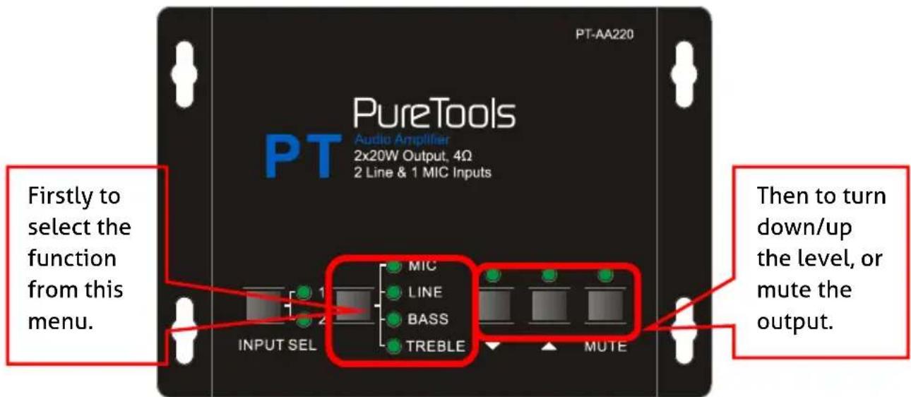
For example, to turn up the line volume, you should select the "LINE" first, and then press the button ▲".
3.2. IR Remote Control
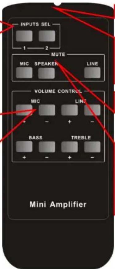
Audio Inputs
■ RCA dual-mono audio inputs
■ 3.5mm jack
Audio Controlling Modes
- MIC: turn up/down the microphone volume.
■ LINE: turn up/down the line volume.
■ BASS: bass tuning - TREBLE: treble of line volume.
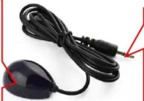
IR receiver head, works in conjunction with the IR remote. Please point the IR remote at the IR receiver when use, to avoid getting out of control as there is no signal detected.
Use to transmit the infrared signal send by the IR remote.
Mute Mode:
■ MIC: Mute the microphone volume.
■ LINE: Mute the line volume.
■ SPEAKER: Unmute
natural_image
Close-up of a black cord with a small electronic device attached, against a white background (no text or symbols visible)3.5mm jack, insert it into the specialized socket (3.5mm) to connect the IR receiver with the amplifier
Note: The IR remote, the IR receiver, and the battery of the IR remote are all offered for charge.
3.3. RS232 Command
Communication Protocol: RS232 Communication Protocol
Baud rate: 9600
Data bit: 8
Stop bit: 1
Parity bit: none
| Command | Function Description | Feedback Code |
| 1A1. | Switching the audio to input 1 | A: 1 -> 1 |
| 2A1. | Switching the audio to input 2 | A: 2 -> 1 |
| 0A0. | Mute Audio of MIC and Line out | Mute |
| 1A0. | Mute audio of MIC | Mute MIC |
| 2A0. | Mute audio of line out | Mute LIN |
| 0A1. | Unmute Audio | Unmute |
| 3A0. | Switch on Noise Gate | Gate On |
| 4A0. | Switch off Noise Gate | Gate Off |
| 600% | Checking the working status | A: 1 -> 1Volume: 30Bass: 00Treble: 00 |
| 601% | MIC volume up | Volume of MIC: 51 |
| 602% | MIC volume down | Volume of MIC: 51 |
| 603% | Line volume up | Volume of LINE: 51 |
| 604% | Line volume down | Volume of LINE: 51 |
| 605% | Bass level up | Bass of LINE: 04 |
| 606% | Bass level down | Bass of LINE: 04 |
| 607% | Treble level up | Treble of LINE: 04 |
| 608% | Treble level down | Treble of LINE: 04 |
| 609% | Initialization, back to the default setting | Init OK |
| 5[x][x]% | Preset MIC volume, [xx] arranges from [00] to [60].61 degrees in total. | Volume of MIC: 50 |
| 7[x][x]% | Preset line volume, [xx] arranges from [00] to [60].61 degrees in total. | Volume of LINE: 50 |
| 8[x][x]% | Preset the bass level, [xx] arranges from [00] to [08].9 degrees in total. | Bass of LINE: 04 |
| 9[x][x]% | Preset the treble level, [xx] arranges from [00] to [08].9 degrees in total. | Treble of LINE: 04 |
Notice:
- The letter inside bracket [ ] is the variable code, which is changeable.
- The bracket [ ] is not included to the RS232 commands.
- Any dot "." after the letters is part of the commands.
Example 1:
Switching the input 2 to the line out, RS232 command is: [2A1.]
Example 2:
Turning up the volume of line audio, RS232 command is: [603%]
Example 3:
Preset the MIC volume to "21" degree, RS232 command is: [521%]
Example 4:
Checking the working status of PT-AA220, RS232 command is: [600%]
- Specification
| Audio Input | |
| Input | (2) stereo audio; (1) MIC |
| Input Connector | (2) RCA; (1) 3.5mm jack;(1) pluggable terminal block (3P,3.81mm), |
| Input Impedance | >10KΩ |
| Audio Output | |
| Output | (1) amplifier; (1) stereo audio |
| Output Connector | (1) 3.5mm jack; (1) pluggable terminal block (4P, 5.08mm) |
| Output Impedance | 50Ω/stereo, 4~8Ω/Amplifier |
| Audio General | |
| Frequency Response | 20Hz ~ 20KHz |
| CMRR | >70dB@20Hz~20KHz |
| SNR | 80dB at maximum output |
| Bandwidth | 20Hz ~ 25KHz |
| Stereo Channel Separation | >75dB@20Hz to 20KHz |
| THD + Noise | 1%@1KHz, 0.3%@20KHz at nominal level |
| Voltage Gain | 32dB |
| Power Output | 2x20 Watts (4 Ohms) |
| Control Function | |
| RS232 Control | 3-hole phoenix connector |
| Panel Control | Optional button control |
| IR Remote | Optional IR remote |
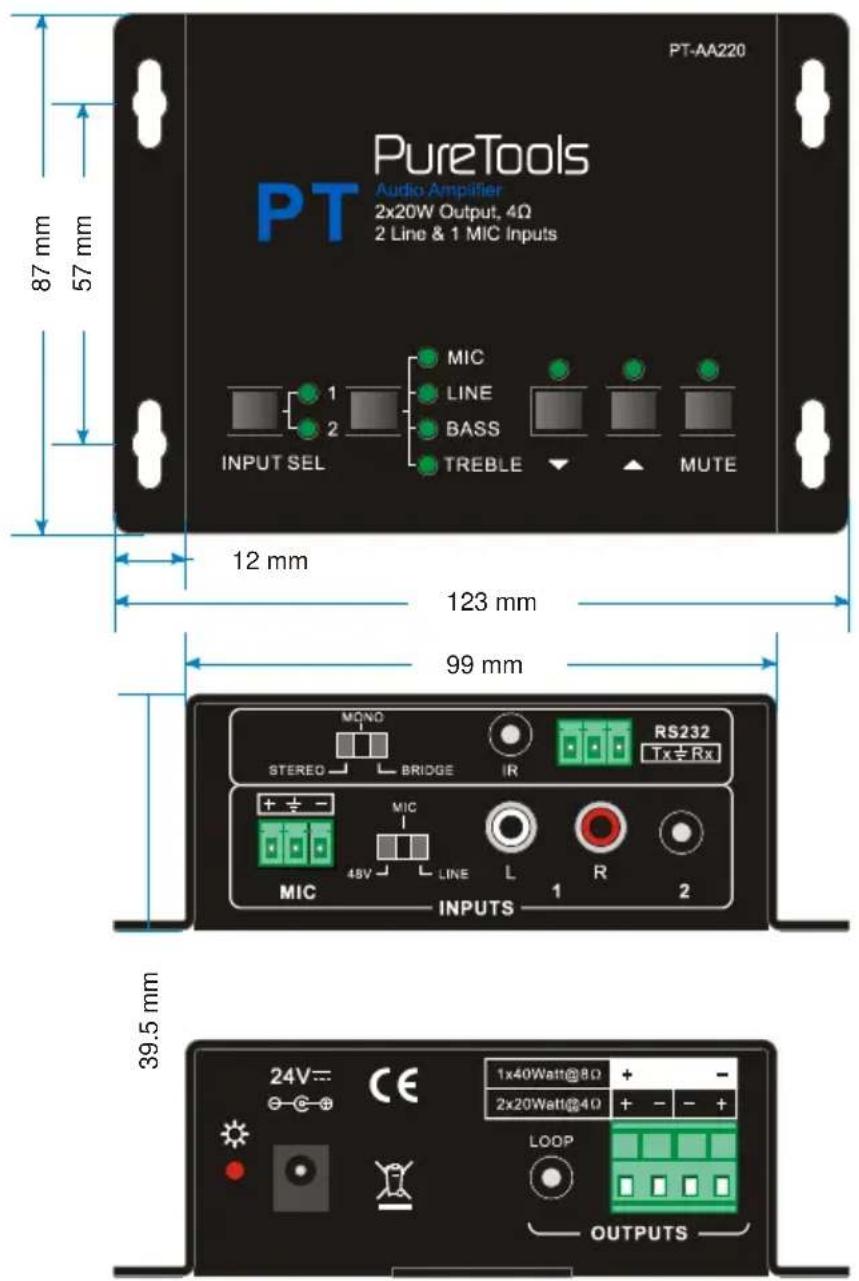
- Panel Drawing
6. Troubleshooting & Maintenance
1) When there is no output audio:
- Check if there is any signal at the input.
- Check if there is any signal at the output.
- We can check these by using an oscilloscope or a multimeter. If there is no signal input/output, maybe the input/output cables broken or the connectors loosen, please change for another cable.
- Check if the output port number is the same with the controlled one.
- If not the problem mentioned above, probably there is something broken inside the unit, please send it to the dealer for repairing.
2) If the POWER indicator doesn't work or no respond to any operation, please make sure the power cord connection is good.
3) If the output sound is interfered, please make sure the system is grounded well.
4) If the static becomes stronger when connecting the audio connectors, it probably due to bad grounding, please check the grounding and make sure it connected well, otherwise it would damage the converter.
5) If the PT-AA220 amplifier cannot be controlled by the keys on the front panel, RS232 port or IR remote, the unit may have already been broken. Please send it to the dealer for repairing.
7. After-Sales Service
If there appear some problems when running the product, please check and deal with the problems referring to this user manual. Any transport costs are borne by the users during the warranty.
1) Product Limited Warranty: This product will be free from defects in materials and workmanship for two years (The purchase invoice shall prevail).
Proof of purchase in the form of a bill of sale or receipted invoice which is evidence that the unit is within the Warranty period must be presented to obtain warranty service.
2) What the warranty does not cover (servicing available for a fee):
- Warranty expiration.
● Factory applied serial number has been altered or removed from the product. -
Damage, deterioration or malfunction caused by:
-
Normal wear and tear.
- Use of supplies or parts not meeting our specifications.
- No certificate or invoice as the proof of warranty.
- The product model showed on the warranty card does not match with the model of the product for repairing or had been altered.
- Damage caused by force majeure.
- Servicing not authorized by distributor.
- Any other causes which does not relate to a product defect.
● Delivery, installation or labor charges for installation or setup of the product.
3) Technical Support: For any questions or problems, contact your distributor or reseller and tell them the respective product name and version, the detailed failure situation as well as the formation of the cases.
Asking for Assistance
Technical Support:
Phone: +49 5971 800299 - 0
Fax: +49 5971 800299 - 99
Technical Support Hours:
8:30 AM to 5:00 PM Monday thru Thursday
8:30 AM to 4:00 PM Friday
Write to:
PureLink GmbH
- User Manual
- Model PT-AA220
- Preface
- Trademarks
- FCC Statement
- EMC / LVD (Electro Magnetic Compatibility / Low Voltage Directive)
- SAFETY PRECAUTIONS
- Contents
- Introduction....1
- System Connection....3
- System Operation....7
- Specification.... 12
- Introduction
- Introduction to PT-AA220
- Feature
- Package List
- Note:
- System Connection
- Audio Output
- Default Output: 2x20Watt@4Ohm
- Bridge Connection: 1x40Watt@8Ohm
- Dual-Mono Output
- Microphone Input
- 48V Phantom Power Input
- MIC Input
- LINE Input
- System Diagram
- System Operation
- Panel Control
- Audio Switching
- Volume/EQ Control
- IR Remote Control
- Audio Inputs
- Audio Controlling Modes
- Mute Mode:
- RS232 Command
- Notice:
- Example 1:
- Example 2:
- Example 3:
- Example 4:
- Troubleshooting & Maintenance
- After-Sales Service
- Asking for Assistance
- Technical Support:
- Technical Support Hours:
- Write to:
Brand : PureLink
Model : PT-AA220
Category : Receiver