MFB-TSA - Cables for Computers and Peripherals Planet - Free user manual and instructions
Find the device manual for free MFB-TSA Planet in PDF.


| Product Type | SFP Mini-GBIC Fiber Optic Transceiver Module |
| Model Series | MFB Series (Fast Ethernet) |
| Data Rate | 100 Mbps (Fast Ethernet) |
| Connector Type | LC Duplex |
| Fiber Mode | Multi-mode or Single-mode (depending on variant) |
| Maximum Distance | Up to 120 km (single-mode) |
| Wavelength | 1310 nm or 1550 nm |
| Operating Temperature | 0 to 60°C (standard) or -40 to 75°C (industrial variants) |
| Laser Safety | Class 1 Laser Product, complies with FDA 21 CFR 1040.10 and 1040.11 |
| Compliance | FCC Class A, CE Mark |
| Hot-Pluggable | Yes, supports hot swapping |
| Diagnostics | Digital Optical Monitoring (DOM) support (implied) |
| RoHS | Compliant |
| Dimensions (approx.) | 56.5 x 13.4 x 8.5 mm (standard SFP form factor) |
| Weight (approx.) | ~25 g |
| Power Consumption | <1 W |
| Warranty | Refer to manufacturer |
| Package Contents | Transceiver module, User's Manual |
Frequently Asked Questions - MFB-TSA Planet
User questions about MFB-TSA Planet
0 question about this device. Answer the ones you know or ask your own.
Ask a new question about this device
Download the instructions for your Cables for Computers and Peripherals in PDF format for free! Find your manual MFB-TSA - Planet and take your electronic device back in hand. On this page are published all the documents necessary for the use of your device. MFB-TSA by Planet.
USER MANUAL MFB-TSA Planet
PLANET Fiber Transceiver
MFB-Series/MGB-Series/MTB-Series
User's Manual
Trademarks
Copyright © PLANET Technology Corp. 2016
Contents are subject to revision without prior notice.
PLANET is a registered trademark of PLANET Technology Corp.
All other trademarks belong to their respective owners.
Disclaimer
PLANET Technology does not warrant that the hardware will work properly in all environments and applications, and makes no warranty and representation, either implied or expressed, with respect to the quality, performance, merchantability, or fitness for a particular purpose.
PLANET has made every effort to ensure that this User's Manual is accurate; PLANET disclaims liability for any inaccuracies or omissions that may have occurred.
Information in this User's Manual is subject to change without notice and does not represent a commitment on the part of PLANET. PLANET assumes no responsibility for any inaccuracies that may be contained in this User's Manual. PLANET makes no commitment to update or keep current the
information in this User's Manual, and reserves the right to make improvements to this User's Manual and/or to the products described in this User's Manual, at any time without notice.
If you find information in this manual that is incorrect, misleading, or incomplete, we would appreciate your comments and suggestions.
FCC Warning
This equipment has been tested and found to comply with the limits for a Class A digital device, pursuant to Part 15 of the FCC Rules. These limits are designed to provide reasonable protection against harmful interference when the equipment is operated in a commercial environment. This equipment generates, uses, and can radiate radio frequency energy and, if not installed and used in accordance with the Instruction manual, may cause harmful interference to radio communications. Operation of this equipment in a residential area is likely to cause harmful interference in which case the user will be required to correct the interference at his own expense.
CE Mark Warning
This is a Class A product. In a domestic environment, this product may cause radio interference, in which case the user may be required to take adequate measures.
WEEE Warning
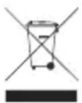
To avoid the potential effects on the environment and human health as a result of the presence of hazardous substances in electrical and electronic equipment, end users of electrical and electronic equipment should understand the meaning of the crossed-out wheeled bin symbol. Do not dispose of WEEE as unsorted municipal waste and have to collect such WEEE separately.
Revision
User's Manual of PLANET SFP/SFP+/XFP Mini-GBIC Transceiver
For Models: MFB-SERIES/MGB-SERIES/MTB-SERIES
Rev: 1.92 (January 2016)
Part No: 2010-AG0220-009
Table of Contents
- Overview 6
- Checklist....7
- Introduction and Model List....8
3-1 The MFB-Series Mini-GBIC Transceiver Module List 8
3-2 The MGB-Series Mini-GBIC Transceiver Module List....12
3-3 The MTB-Series Mini-GBIC Transceiver Module List 17 - Installing SFP / SFP+ / XFP Transceiver Module....20
4-1 Install the SFP / SFP+ Mini-GBIC Transceiver Module 20
4-2 Install the 10GBASE-LR / SR XFP Fiber Optic Module MTB-XSR / MTB-XLR 21
4-3 Remove the SFP / SFP+ / XFP Transceiver Module 22
Appendix A....23
A.1 Fiber Optic Cable Connection Parameters....23
Safety Notice 24
1. Overview
Thank you for purchasing PLANET SFP/SFP+/XFP Mini-GBIC Transceiver which includes the Ethernet module of the MFB/MGB and MTB families.
The MFB family's Fast Ethernet SFP module can be installed into PLANET Switch products with 100BASE-FX SFP interface. The distance can be extended from 2km (Multi-mode, LC) to up to 120km (Single-mode, LC).
The MGB family's Gigabit Ethernet SFP module can be installed into PLANET Switch products with 1000BASE-SX/LX SFP interface. The distance can be extended from 100m (TP) and 550m (Multi-mode, LC) to up to 120km (Single-mode, LC).
The MTB family's 10G Ethernet SFP+/XFP module can be installed into PLANET products with 10G SFP+/XFP interface. The XFP transceivers can be extended from a distance of 300m (Multi-mode, LC) to up to 60km (Single-mode, LC). The SFP+ transceivers can be extended from a distance of 300m (Multi-mode, LC) to up to 60km (Single-mode, LC)
2. Checklist
Your SFP/SFP+/XFP Package should contain the following items:
● The SFP/SFP+/XFP Transceiver Module x 1
- The User's Manual x 1
If any item is missing or damaged, please consult the dealer from whom you purchased your SFP/SFP+/XFP Mini-GBIC Ethernet transceiver module.
3. Introduction and Model List
3-1 The MFB-Series Mini-GBIC Transceiver Module List
Fast Ethernet Transceiver (100BASE-X SFP)
| Model | Speed (Mbps) | Connector Interface | Fiber Mode | Distance | Wavelength (nm) | Operating Temp. |
| MFB-FX 100 LC Multi-Mode | 2km 1310nm 0 ~ 60 °C | |||||
| MFB-F20 | 100 | LC | Single Mode | 20km | 1310nm | 0 ~ 60 °C |
| MFB-F40 | 100 | LC | Single Mode | 40km | 1310nm | 0 ~ 60 °C |
| MFB-F60 | 100 | LC | Single Mode | 60km | 1310nm | 0 ~ 60 °C |
| MFB-F120 | 100 | LC | Single Mode | 120km | 1550nm | 0 ~ 60 °C |
| MFB-TFX | 100 | LC | Multi-Mode | 2km | 1310nm | -40 ~ 75 °C |
| MFB-TF20 | 100 | LC | Single Mode | 20km | 1550nm | -40 ~ 75 °C |
Fast Ethernet Transceiver (100BASE-BX, Single Fiber Bi-directional SFP)
| Model | Speed (Mbps) | Connector Interface | Fiber Mode | Distance Wavelength (TX) | Wavelength (RX) | Operating Temp. |
| MFB-FA20 | 100 WDM (LC) | Single Mode | 20km 1310nm | 1550nm 0 | ~ 60 °C | |
| MFB-FB20 | 100 WDM (LC) | Single Mode | 20km 1550nm | 1310nm 0 | ~ 60 °C | |
| MFB-TFA20 | 100 WDM (LC) | Single Mode | 20km 1310nm | 1550nm -40~75 °C | ||
| MFB-TFB20 | 100 WDM (LC) | Single Mode | 20km 1550nm | 1310nm -40~75 °C | ||
| MFB-TFA40 | 100 WDM (LC) | Single Mode | 40km 1310nm | 1550nm -40~75 °C | ||
| MFB-TFB40 | 100 WDM (LC) | Single Mode | 40km 1550nm | 1310nm -40~75 °C |

natural_image
Warning symbol: white triangle with exclamation mark (no text or numbers)- When shorter-distance single mode fiber cables are used, you might need to insert an in-line optical attenuator in the link to avoid overloading the receiver. Follow the I-TUT G652 document to imitate the fiber cable length.
- The attenuation coefficient mentioned in the following chapters is for reference only.
| Attenuation coefficient | Wavelength region Typical link value |
| 1260nm-1360nm 0.5 dB/km | |
| 1530nm-1565nm 0.4 dB/km |
| SFP ModelPhysicalFiber Cable Length “n” km | MFB-F20MFB-TF20 | MFB-F40 MFB-F60 MFB-F120 | |
| 10 < n < 20 2 dB 4-6 dB 8-10 dB | 25-27 dB | ||
| 20 < n < 40 -- 2-4 dB 6-8 dB 23-25 dB | |||
| 40 < n < 60 -- 2-4 dB 18-20 dB | |||
| SFP ModelPhysicalFiber Cable Length “n” km | MFB-TFA10MFB-TFB10 | MFB-FA20 / MFB-FB20MFB-TFA20 / MFB-TFB20 | MFB-TFA40MFB-TFB40 |
| 10 < n < 20 -- 2 dB 4-6 dB | |||
| 20 < n < 40 -- -- | 2-4 dB | ||
| 40 < n < 60 -- -- -- |
3-2 The MGB-Series Mini-GBIC Transceiver Module List Gigabit Ethernet Transceiver (1000BASE-X SFP)
| Model | Speed (Mbps) | Connector Interface | Fiber Mode | Distance | Wavelength (nm) | Operating Temp. |
| MGB-GT 1000 Copper -- 100m -- 0 ~ 60 °C | ||||||
| MGB-SX | 1000 | LC | Multi-Mode | 550m | 850nm | 0 ~ 60 °C |
| MGB-SX2 | 1000 | LC | Multi-Mode | 2km | 1310nm | 0 ~ 60 °C |
| MGB-LX | 1000 | LC | Single Mode | 10km | 1310nm | 0 ~ 60 °C |
| MGB-L30 | 1000 | LC | Single Mode | 30km | 1310nm | 0 ~ 60 °C |
| MGB-L40 | 1000 | LC | Single Mode | 40km | 1550nm | 0 ~ 60 °C |
| MGB-L50 | 1000 | LC | Single Mode | 50km | 1550nm | 0 ~ 60 °C |
| MGB-L70 1000 LC Single Mode 70km 1550nm 0 ~ 60 °C | ||||||
| MGB-L120 1000 LC Single Mode 120km 1550nm 0 ~ 60 °C | ||||||
| MGB-TSX 1000 LC Multi-Mode 550m 850nm -40 ~ 75 °C | ||||||
| MGB-TLX 1000 LC Single Mode 10km 1310nm -40 ~ 75 °C | ||||||
| MGB-TL30 1000 LC Single Mode 30km 1310nm -40 ~ 75 °C | ||||||
| MGB-TL70 1000 LC Single Mode 70km 1550nm -40 ~ 75 °C | ||||||
Gigabit Ethernet Transceiver (1000BASE-BX, Single Fiber Bi-directional SFP)
| Model | Speed (Mbps) | Connector Interface | Fiber Mode | Distance | Wavelength (TX) | Wavelength (RX) | Operating Temp. |
| MGB-LA10 | 1000 | WDM (LC) | Single Mode | 10km | 1310nm | 1550nm | 0 ~ 60 °C |
| MGB-LB10 1000 WDM (LC) Single Mode 10km 1550nm 1310nm 0 ~ 60 °C | ||
| MGB-LA20 1000 WDM (LC) Single Mode 20km 1310nm 1550nm 0 ~ 60 °C | ||
| MGB-LB20 1000 WDM (LC) Single Mode 20km 1550nm 1310nm 0 ~ 60 °C | ||
| MGB-LA40 1000 WDM (LC) Single Mode 40km 1310nm 1550nm 0 ~ 60 °C | ||
| MGB-LB40 1000 WDM (LC) Single Mode 40km 1550nm 1310nm 0 ~ 60 °C | ||
| MGB-LA60 1000 WDM (LC) Single Mode 60km 1310nm 1550nm 0 ~ 60 °C | ||
| MGB-LB60 1000 WDM (LC) Single Mode 60km 1550nm 1310nm 0 ~ 60 °C | ||
| MGB-TLA10 1000 WDM (LC) Single Mode 10km 1310nm 1550nm -40 ~ 75 °C | ||
| MGB-TLB10 1000 WDM (LC) Single Mode 10km 1550nm 1310nm -40 ~ 75 °C | ||
| MGB-TLA20 1000 WDM (LC) Single Mode 20km 1310nm 1550nm -40 ~ 75 °C | ||
| MGB-TLB20 1000 WDM (LC) Single Mode 20km 1550nm 1310nm -40 ~ 75 °C |
| MGB-TLA40 1 | 000 WDM (LC) | Single Mode 40km | 1310nm | 1550nm | -40 ~ | 75 °C | ||
| MGB-TLB40 1 | 000 WDM (LC) | Single Mode 40km | 1550nm | 1310nm | -40 ~ | 75 °C | ||
| MGB-TLA60 1 | 000 WDM (LC) | Single Mode 60km | 1310nm | 1550nm | -40 ~ | 75 °C | ||
| MGB-TLB60 1 | 000 WDM (LC) | Single Mode 60km | 1550nm | 1310nm | -40 ~ | 75 °C |
| SFP ModelPhysicalFiber Cable Length “n” km | MGB-LX MGB-L30 MGB-L40 MGB-L70 MGB-L120 | ||||
| 10 < n < 20 -- 2-4 dB 5-7 dB 13-15 dB 25-27 dB | |||||
| 20 < n < 40 -- 2 dB 3-5 dB 10-12 dB 23-25 dB | |||||
| 40 < n < 60 -- -- 5-7 dB 18-20 dB | |||||
| SFP ModelPhysicalFiber Cable Length “n” km | MGB-TLX MGB-TL30 MGB-TL70 | |
| 10 < n < 20 -- 2-4 dB 13-15 dB | ||
| 20 < n < 40 -- 2 dB 10-12 dB | ||
| 40 < n < 60 -- -- 5-7 dB |
| SFP ModelPhysical FiberCable Length “n” km | MGB-LA10MGB-LB10MGB-TLA10MGB-TLB10 | MGB-LA20MGB-LB20MGB-TLA20MGB-TLB20 | MGB-LA40MGB-LB40MGB-TLA40MGB-TLB40 | MGB-LA60MGB-LB60MGB-TLA60MGB-TLB60 |
| 10 < n < 20 -- 2 dB 4-6 dB 8-10 dB | ||||
| 20 < n < 40 -- -- 2-4 dB 6-8 dB | ||||
| 40 < n < 60 -- -- -- 2-4 dB |
3-3 The MTB-Series Mini-GBIC Transceiver Module List
10Gbps XFP (10G Ethernet/10GBASE)
| Model Speed (Mbps) | Connector Interface | Fiber Mode Distance | Wavelength (nm) | Operating Temp. |
| MTB-XSR 10G LC Multi-Mode | Up to 300m 850nm | 0 ~ 60 °C | ||
| MTB-XLR 10G LC Single Mode | 10km 1310nm | 0 ~ 60 °C |
10Gbps SFP+ (10G Ethernet/10GBASE)
| Model Speed (Mbps) | Connector Interface | Fiber Mode Distance | Wavelength (nm) | Operating Temp. |
| MTB-SR 10G LC Multi-Mode Up to 300m 850nm 0 ~ 60 °C | ||||
| MTB-LR 10G LC Single Mode 10km 1310nm 0 ~ 60 °C | ||||
| MTB-TSR 10 | G LC Multi-Mode | Up to 300m 850 | nm -40 ~ 75 °C | |||
| MTB-TLR 10 | G LC Single Mode | 10km 1310nm | -40 ~ 75 °C |
10Gigabit Ethernet Transceiver (10GBASE-BX, Single Fiber Bi-directional SFP)
| Model | Speed (Mbps) | Connector Interface | Fiber Mode Distance | Wavelength (TX) | Wavelength (RX) | Operating Temp. | |
| MTB-LA20 MTB-LB20 | 10G | WDM (LC) | Single Mode | 20km | 1270nm | 1330nm | 0 ~ 60 °C |
| 10G | WDM (LC) | Single Mode | 20km | 1330nm | 1270nm | 0 ~ 60 °C | |
| MTB-LA40 MTB-LB40 | 10G | WDM (LC) | Single Mode | 40km | 1270nm | 1330nm | 0 ~ 60 °C |
| 10G | WDM (LC) | Single Mode | 40km | 1330nm | 1270nm | 0 ~ 60 °C | |
| MTB-LA60MTB-LB60 | 10G WDM (LC) Single Mode 60km 1270nm 1330nm 0 ~ 60 °C | ||||||
| 10G WDM (LC) Single Mode 60km 1330nm 1270nm 0 ~ 60 °C | |||||||
| SFP ModelPhysicalFiber Cable Length “n” km | MTB-LA20MTB-LB20 | MTB-LA40MTB-LB40 | MTB-LA60MTB-LB60 |
| 10 < n < 20 2 dB 4-6 dB 8-10 dB | |||
| 20 < n < 40 -- 2-4 dB 6-8 dB | |||
| 40 < n < 60 -- 2-4 dB |
4. Installing SFP/SFP+/XFP Transceiver Module
4-1 Install the SFP/SFP+ Mini-GBIC Transceiver Module
Please follow these steps to install the SFP/SFP+ Mini-GBIC module:
- Power on the Switch and place the Switch on a flat surface. Install the new SFP/SFP+ Mini-GBIC module by inserting it into the slot and sliding it in until it stops (See Figure 1). Press it firmly until you hear the module snap into place. Never force, twist or bend the SFP/SFP+ Mini-GBIC module. The SFP/SFP+ Mini-GBIC module slides in smoothly and the Switch will automatically detect the new module.
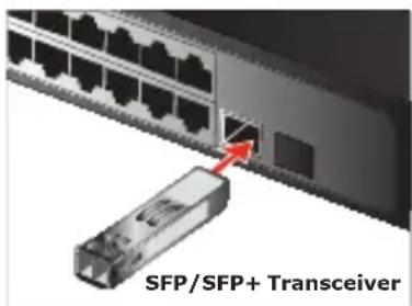
Figure 1: Insert the SFP/SFP+ Mini-GBIC Module
- After the TP/Fiber connection is made successfully, check the LEDs to verify that if there is a link and a proper connection at the port.
Please refer to the user's manual for more about the Switch or module's management.
4-2 Install the 10GBASE-LR/SR XFP Fiber Optic Module MTB-XSR/MTB-XLR
The 10GBASE-LR/SR Fiber Optic module can be installed into Planet products with 10G XFP interface.
Please refer to the following steps to install the 10GBASE-LR/SR Fiber Optic module:
-
Install the XGS3-M24GX or XGS3-S4XG module into the XGS3-42000R; its 10G XFP slot supports hot swappable feature.
-
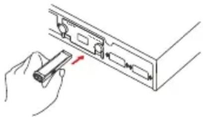
Power on the XGS3-42000R L3 Switch and place the Switch on a flat surface. Install the new 10GBASE-LR/SR Fiber Optic module by inserting it into the slot and sliding it in until it stops (See Figure 2). Press it firmly until you hear the module snap into place. Never force, twist or bend the 10GBASE-LR/SR Fiber Optic module. The 10GBASE-LR/SR Fiber Optic module slides in smoothly and the XGS3-42000R L3 Switch will automatically detect the new module.
natural_image
Illustration of a hand holding a device inside a rack or cabinet (no text or symbols visible)Figure 2: Insert the 10GBASE-LR/SR Fiber Optic Module
- After the 10GBASE-LR/SR Fiber connection is made successfully, check the LNK/ACT LED to verify that if there is a link and a proper connection at the port.
Please refer to the Switch's user's manual for more about Switch or module's management.
4-3 Remove the SFP/SFP+/XFP Transceiver Module
- Make sure there is no network activity by consulting or checking with the network administrator.
- Remove the Fiber Optic Cable gently.
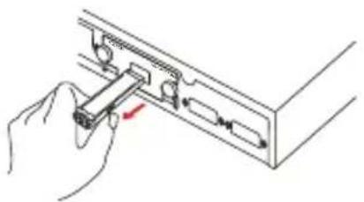
- Turn the handle of the SFP/SFP+/XFP Transceiver module to the horizontal level.
- Pull out the SFP/SFP+/XFP Transceiver module gently through the handle.
natural_image
Hand inserting a component into a device panel (no text or symbols visible)
Never pull out the SFP/SFP+/XFP Transceiver module without pulling the handle or the push bolts on the module. Directly pulling out the SFP/SFP+/XFP Transceiver module would damage the SFP/SFP+/XFP Transceiver module of the device.
Appendix A
A.1 Fiber Optic Cable Connection Parameters
The wiring details are shown below:
■ Fiber Optic Patch Cables:
| Standard Fiber Type | Cable Specifications | |
| 100BASE-FX Multi-mode 50/125μm or 62.5/125μm | ||
| 100BASE-FX Single mode 9/125μm | ||
| 1000BASE-SX Multi-mode 50/125μm or 62.5/125μm | ||
| 1000BASE-LX Single mode 9/125μm | ||
| 1000BASE-BX Single mode 9/125μm | ||
| 10GBASE-SR Multi-mode 50/125μm or 62.5/125μm | ||
| 10GBASE-LR Single mode 9/125μm | ||
| 10GBASE-BX Single mode 9/125μm | ||
Safety Notice
Fiber-optic SFP modules are equipped with a Class 1 laser, which emits invisible radiation. Read the following safety warning carefully.

Note
Class 1 Laser Product
Complies with FDA Regulation 21 CFR 1040.10 and 1040.11

Warning
Class 1 radiation is present when the device or system is powered up.

Warning
Only trained and qualified personnel should be allowed to install or replace these modules.
- PLANET Fiber Transceiver
- MFB-Series/MGB-Series/MTB-Series
- Trademarks
- Disclaimer
- FCC Warning
- CE Mark Warning
- WEEE Warning
- Revision
- Table of Contents
- Overview
- Checklist
- Introduction and Model List
- 3-1 The MFB-Series Mini-GBIC Transceiver Module List
- 3-3 The MTB-Series Mini-GBIC Transceiver Module List
- Installing SFP/SFP+/XFP Transceiver Module
- 4-1 Install the SFP/SFP+ Mini-GBIC Transceiver Module
- 4-2 Install the 10GBASE-LR/SR XFP Fiber Optic Module MTB-XSR/MTB-XLR
- 4-3 Remove the SFP/SFP+/XFP Transceiver Module
- Appendix A
- A.1 Fiber Optic Cable Connection Parameters
- Safety Notice
Brand : Planet
Model : MFB-TSA
Category : Cables for Computers and Peripherals