
VS-XHVR8P-165 - Dictaphone Mach Power - Free user manual and instructions
Find the device manual for free VS-XHVR8P-165 Mach Power in PDF.


| Type | Digital Voice Recorder |
| Model | VS-XHVR8P-165 |
| Brand | Mach Power |
| Dimensions | Approx. 110 x 40 x 15 mm |
| Weight | Approx. 80 g (including battery) |
| Power Supply | Built-in rechargeable lithium battery, USB charging (5V DC) |
| Recording Formats | MP3, WAV (PCM) |
| Storage Capacity | Internal memory 8 GB (expandable via microSD up to 32 GB) |
| Recording Modes | High quality, standard, long play |
| Playback Controls | Play, pause, stop, fast forward, rewind, volume adjust |
| Connectivity | USB 2.0, headphone jack (3.5 mm) |
| Microphone | Built-in omnidirectional, external microphone input (3.5 mm) |
| Speaker | Built-in mono speaker |
| Display | LCD with backlight, shows recording time, battery, file info |
| Battery Life | Up to 20 hours continuous recording |
| Charging Time | Approx. 2-3 hours |
| Included Accessories | USB cable, earphones, user manual, lanyard |
| Warranty | 1 year limited |
| Operating System | Windows, Mac OS, Linux (mass storage class) |
| Security | Password protection for files (via software) |
| Repairability | Battery replaceable by authorized service; microSD slot accessible |
Frequently Asked Questions - VS-XHVR8P-165 Mach Power
User questions about VS-XHVR8P-165 Mach Power
0 question about this device. Answer the ones you know or ask your own.
Ask a new question about this device
Download the instructions for your Dictaphone in PDF format for free! Find your manual VS-XHVR8P-165 - Mach Power and take your electronic device back in hand. On this page are published all the documents necessary for the use of your device. VS-XHVR8P-165 by Mach Power.
USER MANUAL VS-XHVR8P-165 Mach Power
natural_image
Circular icon with a stylized white helmet or helmet symbol on a teal background, enclosed in a white circle (no text or symbols)VMS iSENTINEL LITE
USER MANUAL
Thanks
for choose our product
INDEX
Chapter 1 Software Installation
1.1 Software Installation
1.2 Function Features
Chapter 2 VMS User Manual
2.1 Client's Instructions
2.1.1 Login
2.1.2 Add Hardware Device
2.1.2.1 Scan Hardware Device
2.1.2.1.1 Scan the specified ip address hardware
2.1.2.1.2 Scan the specified manufacturer hardware
2.1.2.1.3 Automatic configuration verification
2.1.2.1.4 Scan all hardware
2.1.2.1.5 Manually verify hardware
2.1.2.1.6 Complete Adding Hardware
2.1.2 Manually Add Hardware
2.1.2.2.1 Add hardware via IP address
2.1.2.2.2 Add hardware via serial number
2.1.2.3 Edit Hardware Properties
2.1.2.3.1 Modify the hardware device name
2.1.2.3.2 Modify thce hardware device port number, user name and password
2.1.2.3.3 Modify the channel name
2.1.3 Storage Configuration
2.1.3.1 Configure the storage path, stream type, retention time
2.1.3.2 Configure the recording type, schedule
2.1.3.3 Templateconfiguration
2.1.4 Server Access
2.1.5 User Management
2.1.5.1 Edit User Information
2.1.5.2 Edit User Permission
2.1.6 Service
2.2 Client Operation Manual
2.2.1 Login
2.2.2 Live Preview
2.2.2.1 Live preview function
2.2.2.2 View Switches To Video
2.2.2.3 Select the Camera to Preview Video
2.2.2.4 PTZ Control
2.2.2.5 Video Window Toolbar Function Description
2.2.3 Playback
2.2.3.1 Playback Interface Function Introduction
2.2.3.2 Switching View to Playback Recording
2.2.3.3 Select Camera Recording Playback
2.2.3.4 Search Recording
2.2.3.4.1 Auto Search Recording
2.2.3.5 Playback Recording
2.2.3.5.1 Playback recording synchronously
2.2.3.5.2 Playback recording independently
2.2.3.5.3 Loop playback recording
2.2.3.6 Export Recording
2.2.4 Management Function
2.2.4.1 Export List
2.2.4.2 View Setting
2.2.4.3 System Parameter Options
2.2.5 Exit
CHAPTER1
SOFTWARE INSTALLATION
1.1 Software Installation
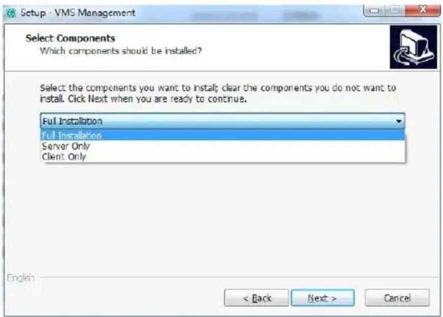
VMS consists of two parts, VMS server and VMS client, you can choose to install server or client installed on the same computer, it can also be installed separately on different local computer, select the default full installation.
CHAPTER2
VMS USER MANUAL
2.1 VMS server user manua
2.1.1 Login

Double click this logo on your desktop, Start the server management program, start interface as the first use of VMS Management program, you need to create a superuser As below, need to create a supper User The first use of VMS Management program, you need to create a superuser.

Use super-user or administrator user login VMS Management

VMS Management landing successfully entered the end of the main management interface

2.1.2 Add hardware
Click getting Started, then click add hardware

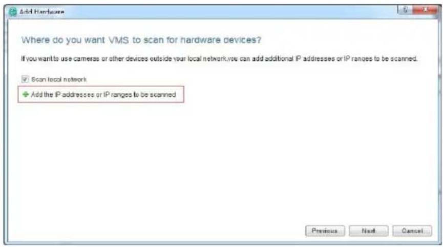
Pop-up dialog box to add add hardware, the hardware scan can scan directly inside the LAN hardware device, you can also scan the specified network hardware; manually add the hardware is added directly to know the address or the serial number of hardware device.

2.1.2.1 Scan hardware

2.1.2.1.1 Scan the specified IP address hardware
IP range can be set to filter search equipment, if you do not specify IP range can click Next to skip
2.1.2.1.2 Scan the specified manufacturers hardware
Manufacturers can be set to filter search equipment, if you do not specify manufacturers can click Next to skip, default all manufacturers.

2.1.2.1.3 Automatic Configuration verification
Add default User name and password, automatic verification scanned hardware devices, (no need to configure automatic verification directly to the next step)

Click out the Dialog which can add user name and secret

2.1.2.1.4 Start searching a device according to the setting mode

2.1.2.1.5 Manually verify hardware

2.1.2.1.6 Complete adding hardware
Choose desired device and then click, next complete new adding device of Search mode.

2.1.2.2 Manually add hardware

2.1.2.2.1 Add hardware via IP address
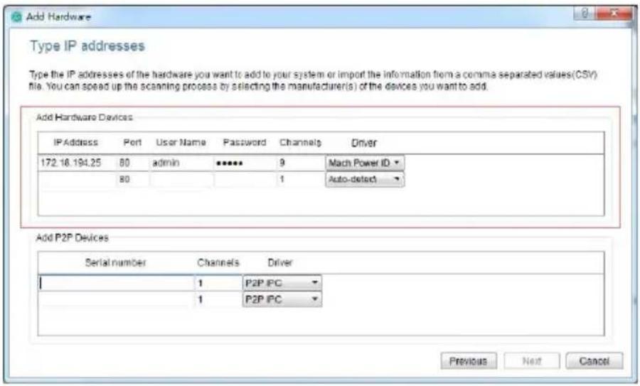
Enter the IP, port number, user name, password, and the number of channels to choose the type of new equipment Driver
2.1.2.2.2 Add hardware via Serial number
Input Devices SN code to add new P2P Device

Complete adding new device manually

2.1.2.3 Edit hardware properties
As shown below, click "1", double click "2."

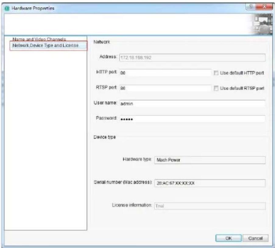
click out the dialog of Hardware Properties

2.1.2.3.1 Modify the hardware device name

2.1.2.3.2 Modify the hardware device port number, user name and password
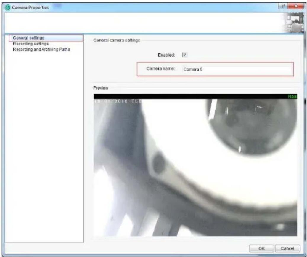
2.1.2.3.3 Modify Channel name
As shown below, click the "1", double click the "2".
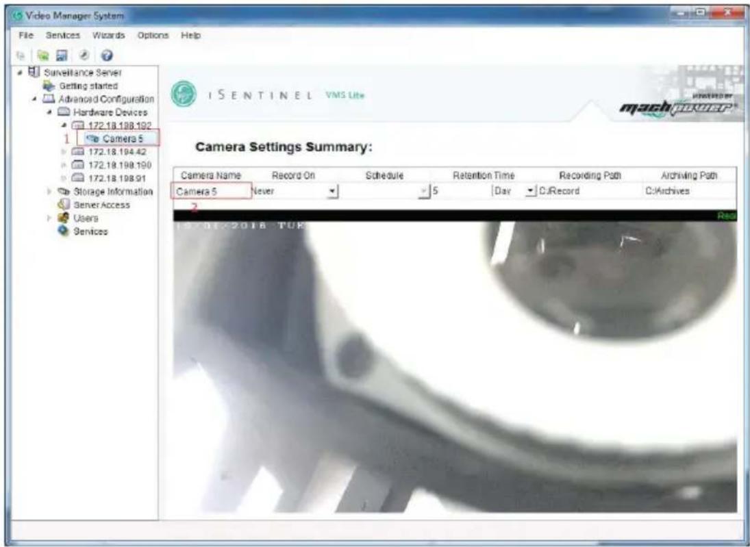
Open camera properties dialog box to modify
2.1.3 Storage configuration
Displays store configuration information of all the devices
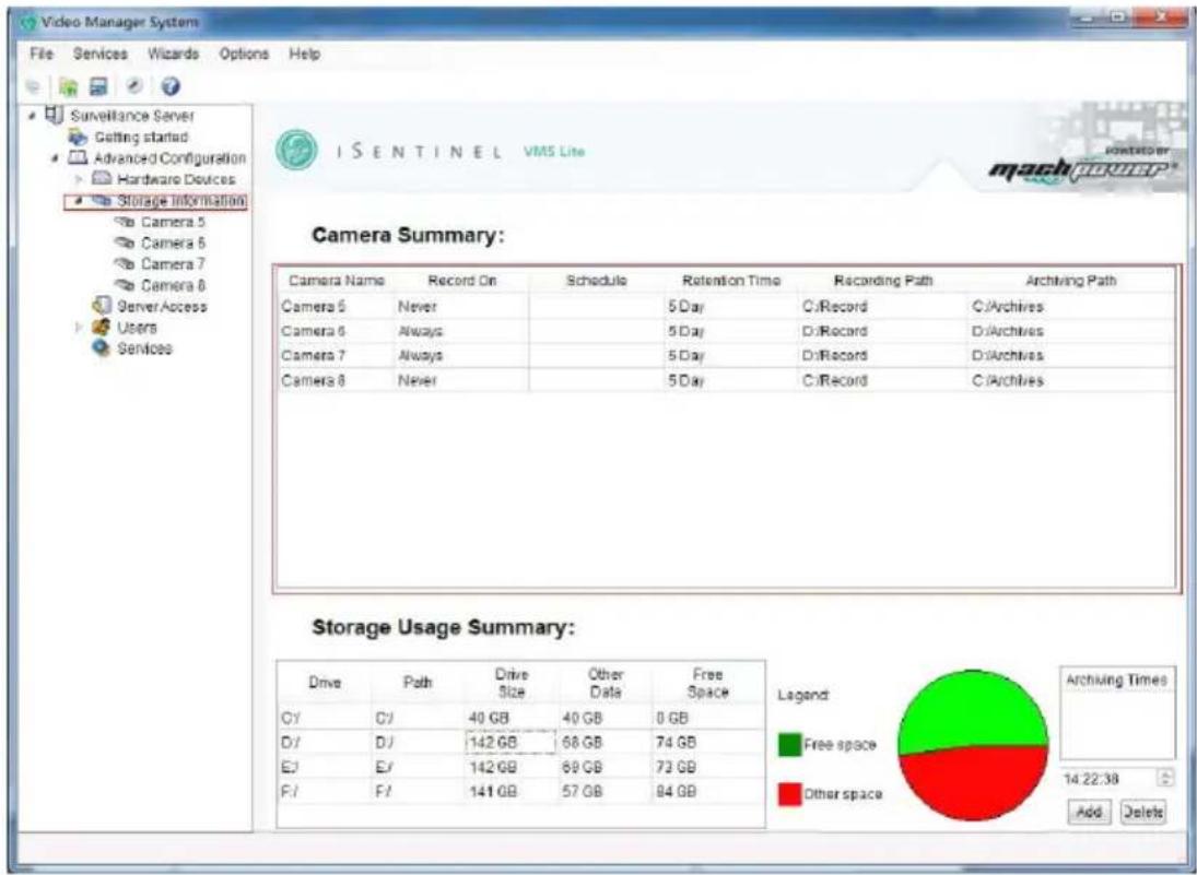
Edit channel storage configuration, double click the list box on the right into the record and storage properties, can only configure one camera, or use the template to configure multi-cameras, (used template configuration see 2.1.3.3);

2.1.3.1 Configure the storage path, stream type, retention time
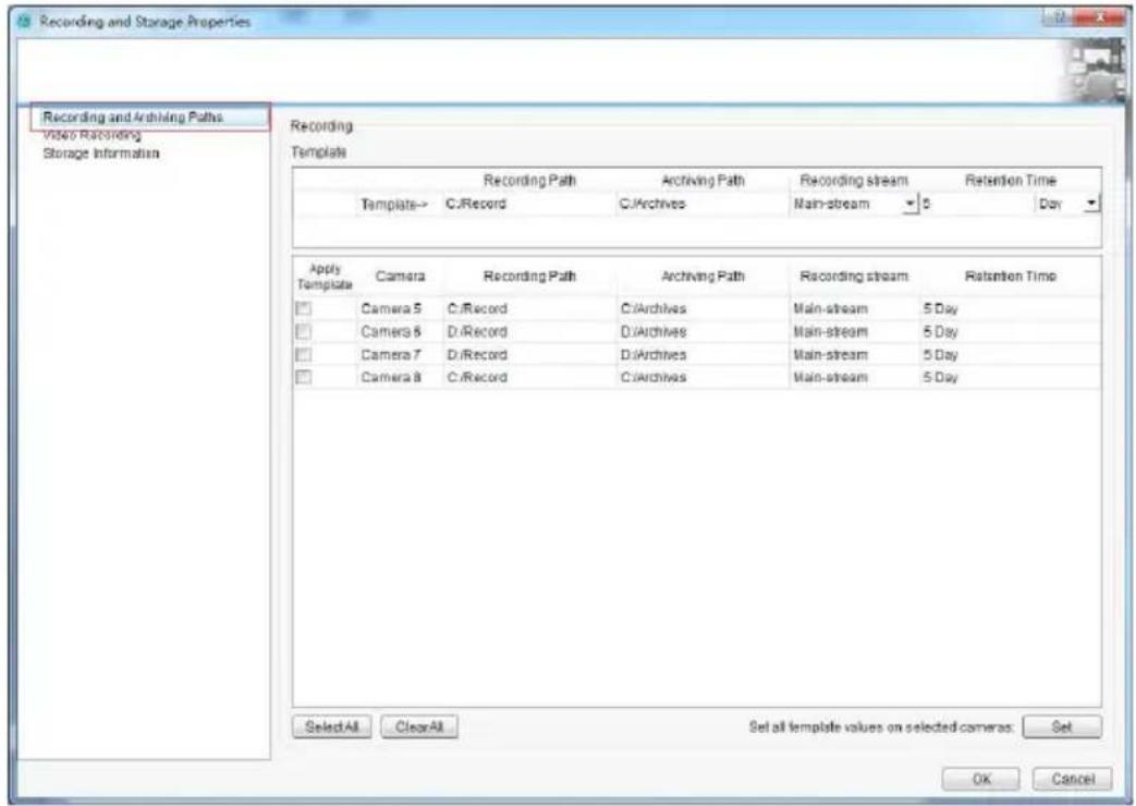
2.1.3.2 Configure the recording type, schedule

2.1.3.3 Template configuration
As shown below:
- Edit the template
- Select the template camera to apply
- Settings applied to the camera

2.1.4 Server access
Set the local port number used for VMS Smart Client logining port number

2.1.5 User management
2.1.5.1 Edit user information
Users List management, open user list window

You can add new users, modify users and delete users in this window.
There are two types of users for option for new users:
- Administrator user (can login both VMS Management and VMS Smart Client)
- Basic users (can only log in VMS SmartClient)
2.1.5.2 Edit user permissions
You can restrict the permission and equipment channel of VMS Smartclient for the specified user.

2.1.6 Service
Background VMS server control.

The usage status of VMS server can be controlled.
Only when the status is started, the VMS server can record and store recordings in the background, and VMS Samrtclient can work normally.
2.2 Client Operation Manual
After the completion of VMS management configuration, the VMS SmartClient can preview and playback video. VMS Smart Client and VMS managent can be installed either in one PC or separately in different ones.
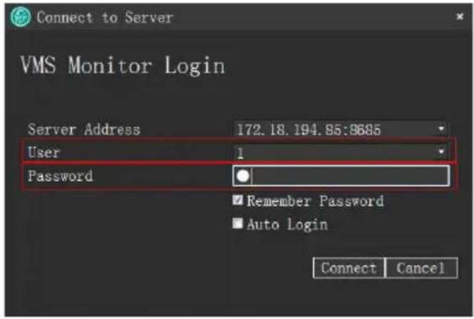
2.2.1 Login
Input the IP and port of the PC where VMS management is installed (If VMS management and VMS smart client are installed in one PC, IP is 127.0.0.1, port is 80 by default., when server access port on VMS management is changed, the port needs to be consistent)

Use the user account created on VMS management to log in and authenticate
2.2.2 Live Preview
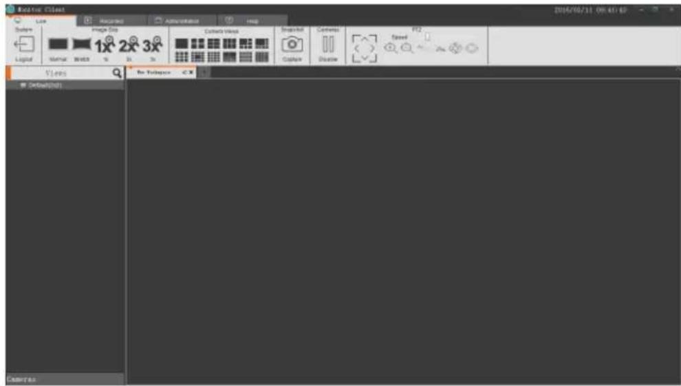
Live preview interface
2.2.2.1 Live preview function

-
Logout: Exit the current user, and return to the login interface
-
Image size
a. Normal: Image is displayed in actual proportion.
b. Stretch: Image is displayed in window size
c. 1x: Image is not scaled
d. 2x: Image is magnified 2 times
e. 3x: Image is magnified 3 times
Camera View: Select the layout type of the view window.
Snapshot: Capture the images of the current window
Close the current camera video
PTZ control (Only valid for the devices that support PTZ control)
2.2.2.2 View Switches To Video
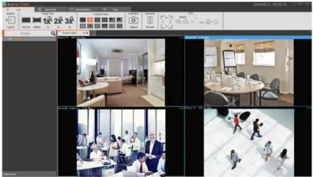
Use the view layout that the user selects to fast switch to view preview
2.2.2.3 Select the Camera to Preview Video
Select the camera to the designated window to preview video.

2.2.2.4 PTZControl
a. Select PTZ Control Window.
b. Do PTZ control for selected Window on PTZ console.

2.2.2.5 Video Window Toolbar Function Description
a. Current Window Video Stop and Start
b. Capture Images
c. Local Recording
d. Voice Intercom e. Volume
f. Stream Switching
g. Digital Zoom

2.2.3 Playback
Playback can be operated under the VMS Server with configuration only.
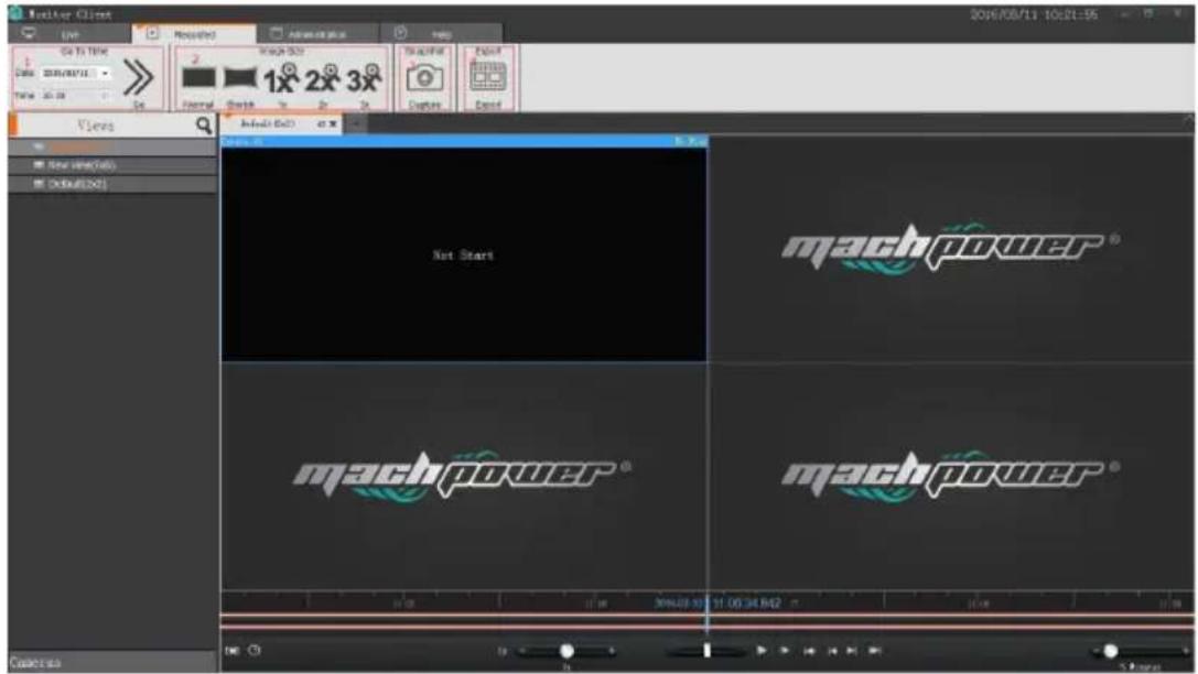
2.2.3.1 Playback Interface Function Introduction
-
Recording Location: according to the selected time & position to locate to the specified place quickly.
-
Image Size:
a. Regular: image be displayed as actual proportion.
b. Stretch: image be displayed as the window size.
c. 1 times: image be not scaled.
d. 2 times: image be magnified 2 times.
e. 3 times: image be magnified 3 times.
2.2.3.2 Switching View to Playback Recording
Using user edited view to switch recording Playback fast.

2.2.3.3 Select Camera recording Playback
Select the camera to be playback and drag to the specified window.
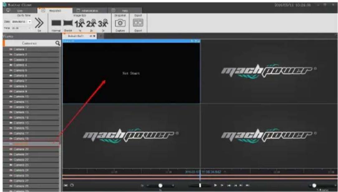
2.2.3.4 Search Recording
2.2.3.4.1 Auto Search Recording
Enter or under playback interface to switch view, it will search the recording time of all windows view automatically, and display them on time Axis.

Time Axis Type:
-
The top Time Axis shows the recording time-line of current selected window.
-
The bottom Time Axis shows the set of all cameras' recording time-lines in current view.

2.2.3.5 Playback recording
2.2.3.5.1 Play back recording synchronously
Click out Play button to start playback, this play mode is to play view synchronously, that's to say, the video in all windows will be played back synchronously.
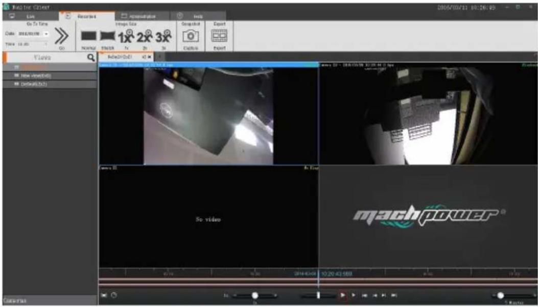
Synchronously playback tools function introduction:

- Playback region: choose playback range, then loop play back in this range.

2.1 Multiply playback: rapidly switch to 1 multiply playback.
3. Playback multiply adjustment.
4. Rapidly retrieve video.
5. Start/ suspend playback.
6. Single frame playback.
7. The first video segment in current window.
8. The previous video segment in current window.
9. The next video segment in current window.
10. The last video segment in current window.
11. View range of time axis.
2.2.3.5.2 Play back recording independently
If only play back the video in a certain window, this function can be used at this time. It will not be controlled by synchronously playback tools. There is easy control bar in the window.
To play back window independently, please click out the playback independently button in window tools.
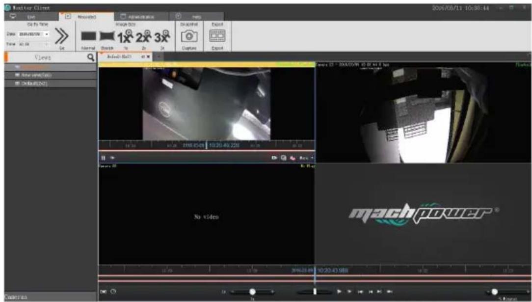
2.2.3.5.3 Loop playback
The video can be loop playback continuously in a designated period of time.

2.2.3.6 Export Recording
The video in service side can be exported at client side according to request. It can export a video from a certain window, also the videos from all windows.
Export recording instruction:
- To select time range.

- Select to export video window.

- Click the Export button.

4. Select the name and location of the exported

5. After the export is completed, in management functions you can view details in the export list

2.2.4 Management Function
2.2.4.1 Export List
See video of the export list information
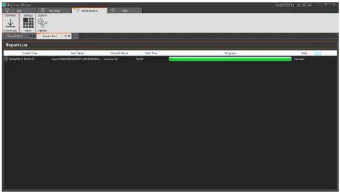
2.2.4.2 View Setting
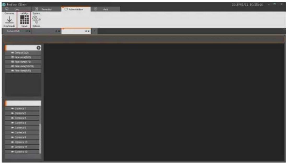
The role of the view that the user can edit the layout and view of the contents in advance, quickly switch the video area. And that will be saved to the VMS platform for later use.
2.2.4.2.1 View Edition
2.2.4.2.1.1 Add View
Click "Add" Botton to choose a type of view layout


2.2.4.2.1.2 View Edition
4 types of view content:
1.camera
2.photo
3. HTML website
4. Video carousel
Select the view for editing

- In the "View Setup", add items, select the camera, drag to the targeted window and complete video addition.

- Set the view window to add a web page
a. Select "HTML Page",
b. Drag to the specified window
c. Input web adress
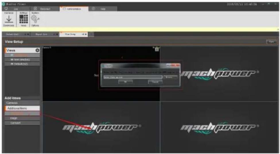
- set the view window to add pictures
a. Click"Image".
b. Drag to the specified window
c. Select pictures.

- Set the view window to add video tour
a. Select "Carousel"
b. Drag to the specified window
c. Select channel of equipment to be round tour
d. Video round tour time
e. The video stream type
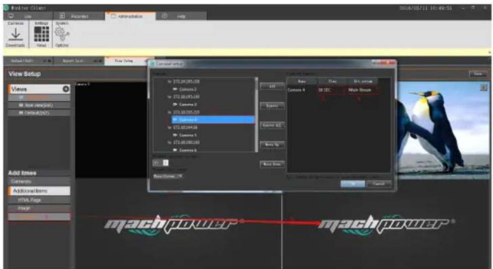
Complete the view editor, click "save" button to save the view to the server.

2.2.4.2.1.3 Modify the view name
Double-click to modify edit view into the state, to modify the view name and then click the "save" button

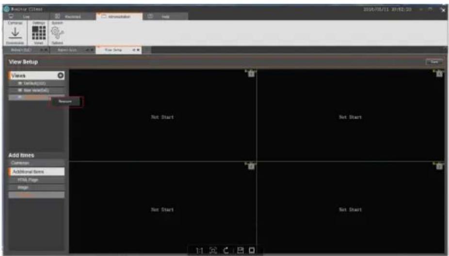
2.2.4.2.1.4 Delete View
Select view right-click pop-up menu select delete the view
2.2.4.3 System parameter options

1. General Options
Login options:
a. Remember the password
b. Auto login
Language option: choose the different language
Storage options:
a. Client local video path
b. Capture path
c. Video export pat
2.2.5 Exit

- VMS iSENTINEL LITE
- USER MANUAL
- Thanks
- for choose our product
- INDEX
- Chapter 1 Software Installation
- Chapter 2 VMS User Manual
- CHAPTER1
- SOFTWARE INSTALLATION
- Software Installation
- CHAPTER2
- VMS USER MANUAL
- VMS server user manua
- Login
- Add hardware
- Scan hardware
- Scan the specified IP address hardware
- Scan the specified manufacturers hardware
- Automatic Configuration verification
- Manually verify hardware
- Complete adding hardware
- Manually add hardware
- Add hardware via IP address
- Add hardware via Serial number
- Edit hardware properties
- Modify the hardware device name
- Modify the hardware device port number, user name and password
- Modify Channel name
- Storage configuration
- Configure the storage path, stream type, retention time
- Configure the recording type, schedule
- Template configuration
- Server access
- User management
- Edit user information
- Edit user permissions
- Service
- Client Operation Manual
- Login
- Live Preview
- Live preview function
- View Switches To Video
- Select the Camera to Preview Video
- PTZControl
- Video Window Toolbar Function Description
- Playback
- Playback Interface Function Introduction
- Switching View to Playback Recording
- Select Camera recording Playback
- Search Recording
- Auto Search Recording
- Time Axis Type:
- Playback recording
- Play back recording synchronously
- Play back recording independently
- Loop playback
- Export Recording
- Select the name and location of the exported
- After the export is completed, in management functions you can view details in the export list
- Management Function
- Export List
- View Setting
- View Edition
- Add View
- View Edition
- Modify the view name
- Delete View
- System parameter options
- General Options
- Login options:
- Storage options:
- Exit
Brand : Mach Power
Model : VS-XHVR8P-165
Category : Dictaphone