
UD/S4.315.2 - Home Automation ABB - Free user manual and instructions
Find the device manual for free UD/S4.315.2 ABB in PDF.


| Product Type | Universal Dimming Actuator for KNX systems |
| Dimensions | 144 mm (8 part units) for 4-gang models; 216 mm (12 part units) for 6-gang models |
| Power Supply | 230 V AC ±10%, 50/60 Hz |
| Standby Power Loss | 1.0 - 1.5 W (depending on number of occupied channels) |
| Number of Channels | 1, 4, or 6 (depending on variant) |
| Switching Capacity | Up to 2400 W/VA per channel (varies by model) |
| Load Types Supported | 230 V incandescent lamps, 230 V halogen lamps, low-voltage halogen lamps with conventional or electronic transformers |
| Protection Type | IP20 |
| Operating Temperature Range | -5°C to +45°C |
| Connection | Screw terminals (1-6 mm²) for mains; screwless bus connecting terminal for KNX |
| Functions | Switching, relative/absolute dimming, staircase lighting, light scenes, sequence, logic, gate, min/max value transducer, threshold value/hysteresis, PWM inverter, priority, error signaling |
| Maintenance | Maintenance-free; clean with dry or slightly moist cloth (mild soap solution) |
| Safety | Installation only by authorized electricians; disconnect mains before installation; electronic short-circuit and overload protection |
| Firmware Update | Via 10-pole interface using commissioning adapter (6149/21-500) |
Frequently Asked Questions - UD/S4.315.2 ABB
User questions about UD/S4.315.2 ABB
0 question about this device. Answer the ones you know or ask your own.
Ask a new question about this device
Download the instructions for your Home Automation in PDF format for free! Find your manual UD/S4.315.2 - ABB and take your electronic device back in hand. On this page are published all the documents necessary for the use of your device. UD/S4.315.2 by ABB.
USER MANUAL UD/S4.315.2 ABB
KNX Technical Reference Manual
ABB i-Bus ® KNX Universal dimming actuators
Universal dimming actuators
1 - 4gang 6197/12-101-500
1 - 4gang 6197/13-101-500
1 - 4gang 6197/15-101-500
1 - 6gang 6197/14-101-500
1gang 6197/52-101-500
1gang 6197/53-101-500
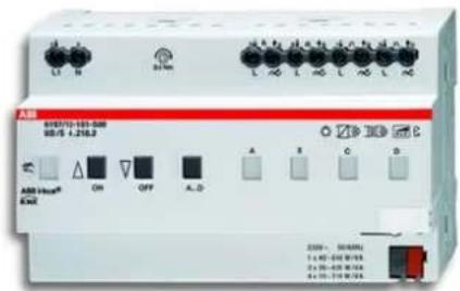
The new universal dimming actuators are suitable for controlling incandescent lamps, 230 V tungsten halogen lamps and low-voltage halogen lamps with conventional or electronic transformers.
They are MDRC devices.
All new: a variable concept allows the parallel switching of several channels (does not apply to 6197/52-101-500 and 6197/53-101-500). This allows the actuator to be perfectly adapted to the connected load.
1 Safety....3
2 Intended use .... 3
3 User information....4
4 Environment....4
5 Technical data....5
6 Function 5
7 Connection....6
7.1 Requirements for the electrician 6
7.2 Electrical connection 7
7.3 Reduction of the connected load 8
8 Start-up 9
8.1 Group formation with Power-Tool 9
9 Commissioning 10
9.1 Parallel connection of channels 10
10 Update 11
11 Operation 12
11.1 Control elements for 1-channel device....12
11.2 Control elements for 4- and 6-channel device....12
11.3 Error messages.... 13
12 Cleaning....14
13 Maintenance 14
14 Object descriptions 15
14.1 Switch object.... 15
14.2 Relative dimming 16
14.3 Value....16
14.4 Enable....17
14.5 Response switching....17
14.6 Response value 17
14.7 Error....18
14.8 Dimming speed for switching on 18
14.9 Dimming speed for switching off 19
14.10 Relative dimming speed for dimming brighter 20
14.11 Relative dimming speed for dimming darker 21
14.12 Absolute dimming speed for dimming brighter 22
14.13 Absolute dimming speed for dimming darker 23
14.14 Delay....24
14.15 Staircase lighting....25
14.16 Light scene actuator....26
14.17 Sequence 26
14.18 Cyclic telegram 27
14.19 Flashing 28
14.20 Logic 28
14.21 Gate 29
14.22 Min/Max value transducer 30
14.23 Threshold value / hysteresis 31
14.24 PWM inverter 32
14.25 Priority 33
1 Safety

Warning
Electric voltage!
Risk of death and fire due to electrical voltage of 230 V.
- Work on the 230V supply system may only be performed by authorised electricians!
- Disconnect the mains power supply prior to installation and/or disassembly!
2 Intended use
- The 1, 4(6)gang universal dimming actuator is intended for the activation and dimming of the following types of loads.
- 230 V incandescent lamps
- 230 V halogen lamps
– Low voltage halogen lamps with conventional or electronic transformers
| Load types | 230 V incandescent lamps | |
| 230 V halogen lamps | ||
| Low-volt halogen lamps with conventional transformers or electronic transformers |
- The device must only be installed on mounting rails according to DIN EN 500022.
- Dimmer capacities > 1000 W only for professional use according to EN 61000-3-2.
- The universal dimming actuator is designed for multi-phase operation and in this mode goes beyond the scope of validity of EN 60669-2-1.
- During the operation of conventional transformers, each transformer must be fuse-protected on the primary side according to manufacturer's specifications.

Note
Only safety transformers according to DIN VDE 0551 are to be used.

Caution
Risk of damaging the device!
For parallel switching of channels (does not apply to 6197/52-101-500 and 6197/53-101-500), these must be connected to the same phase. In case of different phases, the dimmer will be destroyed during parallel switching.
Operation with isolating transformer networks with a connected load of ≤ 10 kVA is not admissible!
The dimmers are not to be operated without load.
3 User information

Disclaimer
The content of this printed material has been checked for compliance with hardware and software.
However, no liability can be assumed for any deviations that may still occur. Any necessary corrections will be implemented in future versions of this manual.
Please advise us of any suggestions you may have concerning the manual's improvement.
4 Environment

Consider the protection of the environment!
Used electric and electronic devices must not be disposed of with domestic waste.
- The device contains valuable raw materials which can be recycled. Therefore, dispose of the device at the appropriate collecting depot.
All packaging materials and devices bear the markings and test seals for proper disposal. Always dispose of the packaging material and electric devices and their components via the authorized collecting depots and disposal companies.
The products meet the legal requirements, in particular the laws governing electronic and electrical devices and the REACH ordinance.
(EU Directive 2002/96/EC WEEE and 2002/95/EC RoHS)
(EU REACH ordinance and law for the implementation of the ordinance (EC) No.1907/2006)
5 Technical data
| Power supply 230 V AC ± 10%, 50/60 Hz | ||
| Standby power loss (dependent on the number of occupied channels) | 1.0 - 1.5 W | |
| Connecting terminals Screw-type terminals, 1 - 6 mm | 2 | |
| KNX connection Bus connecting terminal, screwless | ||
| Power output 6197/52-101-500 | 6197/53-101-500 | 1 |
| 6197/12-101-500 | 4 | |
| 6197/13-101-500 | ||
| 6197/15-101-500 | ||
| 6197/14-101-500 | 6 | |
| Switching voltage 230 V AC, 50/60 Hz | ||
| Switching capacity 6197/12-101-500 = 4 x 10 - 210 W/VA | 6197/13-101-500 = 4 x 10 - 315 W/VA | |
| 6197/14-101-500 = 6 x 40 - 315 W/VA | ||
| 6197/15-101-500 = 4 x 40 - 600 W/VA | ||
| 6197/52-101-500 = 1 x 100 - 1260 W/VA | ||
| 6197/53-101-500 = 1 x 200 - 2400 W/VA | ||
| Protection type IP20 according to DIN EN 60529 | ||
| Operating temperature range -5°C to +45°C | ||
| Short-circuit protection electronic | ||
| Overload protection electronic | ||
| Width | 6197/12-101-500 | 144 mm / 8 part units |
| 6197/13-101-500 | ||
| 6197/52-101-500 | ||
| 6197/14-101-500 | 216 mm / 12 part units | |
| 6197/15-101-500 | ||
| 6197/53-101-500 | ||
| Load types 230 V incandescent lamps | ### [YHZX] | |
| ### [S6HX] | 230 V halogen lamps | |
###  | Low-volt halogen lamps with conventional transformers or electronic transformers | |
6 Function
- The 1, 4(6)gang universal dimming actuator is an MDRC module. The dimming actuator makes possible the activation and dimming of the load types listed in chapter "Intended Use".
• Multiple consumers can be connected to a channel.

Note
Observe the instructions of the manufacturer of the lamps with regard to parallel switching.
Observe also the details in chapter "Commissioning".
- The programmed settings are retained after a power failure.
7 Connection
7.1 Requirements for the electrician

Warning
Electric voltage!
Install the device only if you have the necessary electrical engineering knowledge and experience.
- Incorrect installation endangers your life and that of the user of the electrical system.
- Incorrect installation can cause serious damage to property, e.g. due to fire.
The minimum necessary expert knowledge and requirements for the installation are as follows:
- Apply the "five safety rules" (DIN VDE 0105, EN 50110):
- Disconnect from power;
- Secure against being re-connected;
- Ensure there is no voltage;
-
Connect to earth;
-
Cover or barricade adjacent live parts.
-
Use suitable personal protective clothing.
- Use only suitable tools and measuring devices.
- Check the type supply network (TN system, IT system, TT system) to secure the following power supply conditions (classic connection to ground, protective earthing, necessary additional measures, etc.).
7.2 Electrical connection
The electrical connection is made via screw terminals. The description of the terminals is found on the housing. The connection to KNX is made with the enclosed bus connection terminal. An LS 16 is to be used as circuit breaker.
Polyphase operation Single-phase operation, multichannel dimming actuator


Single-phase operation, 1-channel dimming actuator 1-channel operation (all outputs switched in parallel)

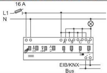
Fig.1: Operating modes

Note
When operating with several single-phase earth leakage circuit breakers there is the risk of voltage displacement between the phases. This can impair the function of the device.
7.3 Reduction of the connected load
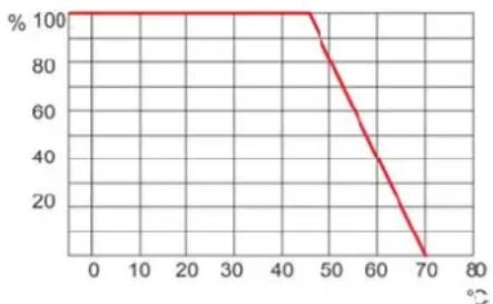
The dimming actuator heats up during operation because part of the connected load is lost and converted into heat. The specified rated power is designed for dimming actuator installation in a solid masonry wall. When installing the dimming actuator in a wall made of glass concrete, wood, or plasterboard, the maximum connection load must be reduced by 20%.
The connected load must always be reduced when several dimming actuators are installed one below the other or when other heat sources cause additional heating. In intensely heated-up rooms, the maximum connected load must be reduced according to the following diagram.
line
| x (°) | y (%) | |---|---| | 0 | 100 | | 45 | 100 | | 70 | 0 |Fig. 2: Maxi mum connected load independence of the ambient temperature
The maximum admissible connected load of 100% is permitted only in the temperature range of -5irc C to 45irc C.
8 Start-up
If the load during initial commissioning is larger than the maximum load of the bridged channels, a group formation of the channels can be used depending on the type used (does not apply to 6197/52-101-500 and 6197/53-101-500). The group formation is carried out with the Power-Tool commissioning software.
8.1 Group formation with Power-Tool
The device is preset as 4 or 6-channel device in Power-Tool under parameter setting "MDRC dimmer / general function / group formation".
If the channels are switched in parallel for the load increase, this must be imaged in Power-Tool. For this, one dimming actuator group is created in the Power-Tool for each channel switched in parallel. A dimming actuator group can be made up of several channels or only a single channel.

Note
Observe also the details in chapter "Commissioning".
9 Commissioning

Caution
Risk of damaging the device!
- A waiting period of 30 seconds is to be observed when re-activating via circuit breakers.
- When commissioning with commissioning adapter 6149/21-500, the latest firmware version of the commissioning adapter is to be used. The version is indicated in the display of the commissioning adapter. The latest firmware version is available in the online catalogue for downloading.

Caution
Malfunction!
The dimming actuators carry out an automatic load test during commissioning. The channels / groups will not be recognized when commissioning without load.
- The dimming actuators are not to be operated without load.
At the point of delivery the dimming actuator has 4 (6) individual pre-programmed channels. If a group formation is required for a load increase (does not apply to 6197/52-101-500 and 6197/53-101-500), it must be carried out with the Power-Tool commissioning software.
The universal dimming actuator detects the connected load automatically after the mains voltage is supplied. If problems arise, the operating mode can be changed individually for each channel via the Power-Tool commissioning software. After a power failure the dimming actuator returns to the parameterized settings.
The physical address is assigned and the parameters are set with the Engineering Tool Software ETS (from version ETS3d). The appropriate commissioning software must be used for the parameter settings. During initial commissioning and prior to connection, the device can be operated manually via the local control.
9.1 Parallel connection of channels

Note
Does not apply to 6197/52-101-500 and 6197/53-101-500.

Caution
Risk of damaging the device!
For parallel switching of channels, these must be connected to the same phase. In case of different phases, the dimming actuator will be destroyed during parallel switching.
- Operation with isolating transformer networks with a connected load of ≤ 10 kVA is not admissible!
A mixture of inductive loads (L) and capacitive loads (C) on the one channel is not admissible.
The channels can be arbitrarily switched in parallel for increasing the power. The universal dimming actuator detects the parallel connection automatically after the mains voltage is supplied.
10 Update
The 10-pole interface on the front of the device makes the device capable of being updated via the commissioning interface / adapter (6149/21-500).
The status of the firmware is indicated with a label on the device, or it can be read via the commissioning adapter.
The firmware version of the adapter can be displayed on the adapter as described in the following:
- Switch the adapter on.
- Navigate with the button to menu item "Status of device".
- Confirm the selection with "OK".
- The current firmware of the adapter (e.g., Version 01.00) and the connected device are displayed.
- Exit the menu item with "ESC".
The current firmware for downloading is available online (online Busch-Jaeger catalogue).
To install the current firmware on the device proceed as follows:
- Create the following directory on the SD card: EMIBUPD.
- Copy the required firmware into this directory, e.g. "6x20_v1.upd".
- Connect the adapter with the enclosed flat cable with the 10-pole user interface of the bus coupler, FM.
- Navigate with the buttons to menu item "SD card".
- Confirm the selection with "OK".
- In this directory select the folder "EMIBUPD".
- In this directory select the file for updating, e.g. "6x20_v1.upd".
- Confirm the selection with "OK".
- The update is started. The progress is shown in the display via a bar graph.
- After the successful download, "OK" appears in the display.
- Exit the directory via the "ESC" key.
11 Operation
11.1 Control elements for 1-channel device

Fig. 3: 1-channel device
11.2 Control elements for 4- and 6-channel device

Fig. 4: 4- and 6-channel device
Control element Function
| 1 Manual operation (local control) | ||
| 2 | Channel | selection |
| 3 | Programming | button |
| 4 | Channel | display |
| 5 Switch off / dim darker | ||
| 6 Switch on / dim brighter | ||
| 7 Commissioning adapter interface for firmware update and KNX programming | ||
Switchover, manual use - KNX operation
To operate the dimming actuator, press button (1) on the device. If the LED on the button lights up red, the channels can be operated manually. Activation via the bus is blocked. To switch over to KNX mode, press button (1) again.
Switching on/off, dimming darker/brighter
The selected channel can be switched on (press briefly) or dimmed brighter (keep button pressed) with the ON button (6) and switched off (press briefly) or dimmed darker (keep button pressed) with the OFF button (5).
Channel status
Signalling "Channel ON/OFF" via green channel LED (4):
- Channel OFF: the channel LED goes out.
- Channel ON: the channel LED lights up permanently.
The devices are pre-programmed. This makes manual group formation or operating mode switchover unnecessary! It is carried out with the Power-Tool commissioning software.
11.3 Error messages
In case of an error, button "Local control" (1) begins to flash. Errors are displayed via different flashing cycles of the related red channel LED (4). To signal the errors, press the "Local control" button (1). They are displayed as longs as it is pressed:
| Error | Flashing | cycle |
| Excess temperature 1 flash - | ||
| Short-circuit | 2 | flashes |
| Wire break or missing load 3 flashes Here the device is to be operated under load. | ||
| Overvoltage | 4 | flashes |
| Internal protective shutdown (e.g. defective output) 5 flashes - | ||
If an error occurs during operation, the channel is deactivated. The green channel LED goes out. When it is re-activated, a check is made if the error still exists (re-activation delay of 30 seconds).
12 Cleaning
Dirty units can be cleaned with a dry cloth. If this is not sufficient, a cloth slightly moistened with soap solution can be used. Caustic cleaning agents or solvents must not be used.
13 Maintenance
The unit is maintenance-free. In case of damage (e.g., during shipping or storage), do not perform repairs.

Note
Only safety transformers according to DIN VDE 0551 are to be used.
14 Object descriptions
14.1 Switch object
Switching on occurs via this 1-bit communication object for receipt of an ON telegram.
The receipt of an OFF telegram switches off. This communication object is only visible if the "Switching status" parameter is set to "via own object", i.e. the object does not send out status telegrams.
Object, switch object
| No. | Object | name | Data | type | Flags | ||
| 0 | Switch | object | 1 | Bit | EIS1 / DPT 1.001 | C, W |
Switching on occurs via the following 1-bit communication object when an ON telegram is received.
The receipt of an OFF telegram switches off. This communication object is only visible if the "Switching status" parameter is set to "via switch object". This means that if the dimming actuator is switched on or dimmed, a status telegram is also sent out with the corresponding dimming value via this object. An ON telegram when switched on, or the value greater than "0" was called up, and an OFF telegram when the output was switched off or was dimmed out.
Object, switch object
| No. | Object | name | Data | type | Flags | ||
| 0 | Switch | object | 1 | Bit | EIS1 / DPT 1.001 | C, R, W, T |
14.2 Relative dimming
Dimming according to the KNX standard (EIS2) takes place via this 4-bit communication object. Start-stop dimming or step-type dimming can be selected.
0 = Stop
1 = 100% dimming darker
2 = 50% dimming darker
3 = 25% dimming darker
4 = 12.5% dimming darker
5 = 6.25% dimming darker
6 = 3.2% dimming darker
7 = 1.6% dimming darker
8 = Stop
9 = 100% dimming brighter
10 = 50% dimming brighter
11 = 25% dimming brighter
12 = 12.5% dimming brighter
13 = 6.25% dimming brighter
14 = 3.2% dimming brighter
15 = 1.6% dimming brighter
Object, relative dimming
| No. | Object name Data type Flags | ||
| 1 Relative dimming 4 Bit EIS2 / DPT 3.007 C, W | |||
14.3 Value
The output is dimmed to the corresponding value via this 1-byte communication object for receipt of a value telegram.
This communication object is only visible if the "Status dimming value" parameter is set to "via own object". This means that the object does not send out status telegrams.
Object, value
| No. | Object name Data type Flags | ||
| 2 Value | 1 Byte EIS6 / DPT 5.001 C, T |
The output is dimmed to the corresponding value via the following 1-byte communication object when a value telegram is received.
This communication object is only visible if the "Status dimming value" parameter is set to "via value object". This means that if the dimming actuator is switched on or dimmed, a status telegram is also sent out with the corresponding dimming value via this object.
Object, value
| No. | Object name Data type Flags | |
| 2 Value | 1 Byte EIS6 / DPT 5.001 C, R, W, T |
14.4 Enable
The dimming actuator can temporarily be blocked via this 1-bit communication object.
Whether the dimming actuator is blocked for receipt of an ON or OFF telegram depends on the setting of the "Object value enable object" parameter.
Object, enable
| No. | Object name Data type Flags | ||
| 3 Enable | 1 Bit EIS1 / DPT 1.001 C, W |
14.5 Response switching
The status of the dimming actuator is sent on the bus via this 1-bit communication object.
This communication object is only visible if the "Switching status" parameter is set to "via own object". This means that if the dimming actuator is switched on or dimmed, a status telegram is also sent out via this object. An ON telegram when switched on or the value greater than "0" was called up, and an OFF telegram when the output was switched off or was dimmed out.
Object, response switching
| No. | Object name Data type Flags | ||
| 4 Response switching 1 Bit EIS1 / DPT 1.001 C, R, T | |||
14.6 Response value
The status of the dimming actuator is sent on the bus via this 1-byte communication object.
This communication object is only visible if the "Status dimming value" parameter is set to "via own object". This means that if the dimming actuator is switched on or dimmed, a status telegram is also sent out with the corresponding dimming value via this object. This communication object is only visible if the "Switching status" parameter is set to "via own object". This means that if the dimming actuator is switched on or dimmed, a status telegram is also sent out via this object. An ON telegram when switched on or the value greater than "0" was called up, and an OFF telegram when the output was switched off or was dimmed out.
Object, response value
| No. | Object | name | Data | type | Flags | ||
| 5 | Response value | 1 | Byte EIS6 / DPT 5.001 | C, R, T |
14.7 Error
A telegram can be sent on the bus via this 1-byte communication object in case of a fault.
The error messages correspond to the messages that are displayed on the device via the error LED (multiple flashing). These are the following errors in detail:
| Error type Sent-out 1-byte value Number of flashing error LEDs | ||
| No error 0 0 | ||
| Excess temperature 1 1 | ||
| Short-circuit | 2 | 2 |
| Wire break or missing load 3 3 | ||
| Overvoltage | 4 | 4 |
| Serious hardware error 5 5 |
Object, error
| No. | Object name Data type Flags | |
| 6 Error | 1 Byte EIS14 / DPT 5.010 C, R, T |
14.8 Dimming speed for switching on
Via this 2-byte communication object it is possible to modify the dimming speed without having to place the dimming actuator into operation again. Values from 0 to 65,535 can be received here. Here value 0 means 0 s and value 65,535 means 6,553,5 s. Speed values received are written into the memory of the dimming actuator and are retained when the bus voltage fails and is again returned.
The communication object is only visible if the "Dimming speed at switching on via data point modifiable" parameter is activated.
Object, dimming speed for switching on
| No. | Object name Data type Flags | ||
| 7 Dimming speed for switching on 2 Byte / DPT 7.004 C, W, U | |||
Via the following 2-byte communication object it is possible to modify the dimming speed without having to place the dimming actuator into operation again. Values from 0 to 65,535 can be received here. Here value 0 means 0 s and value 65,535 means 6,553.5 s. The speed values received are written into the memory of the dimming actuator and are retained when the bus voltage fails and is again returned.
The communication object is only visible if parameters "Dimming speed at switching on via data point modifiable" and "Data point status" are activated. The last setting has the effect that after bus voltage failure and return the speed values of linked communication objects are read automatically (I = reading on initialisation).
Object, dimming speed for switching on
| No. | Object name Data type Flags | ||
| 7 | Dimming speed for switching on | 2 Byte / DPT 7.004 | C, W, T, U, I |
14.9 Dimming speed for switching off
Via this 2-byte communication object it is possible to modify the dimming speed without having to place the dimming actuator into operation again. Values from 0 to 65,535 can be received here. Here value 0 means 0 s and value 65,535 means 6,553,5 s. Speed values received are written into the memory of the dimming actuator and are retained when the bus voltage fails and is again returned.
The communication object is only visible if the "Dimming speed for switching off via data point modifiable" parameter is activated. The communication object is only visible if the "Dimming speed at switching on via data point modifiable" parameter is activated.
Object, dimming speed for switching off
| No. | Object | name | Data | type | Flags | ||
| 8 Dimming speed for switching off 2 Byte / DPT 7.004 C, W, U | |||||||
Via the following 2-byte communication object it is possible to modify the dimming speed without having to place the dimming actuator into operation again. Values from 0 to 65,535 can be received here. Here value 0 means 0 s and value 65,535 means 6,553.5 s. The speed values received are written into the memory of the dimming actuator and are retained when the bus voltage fails and is again returned.
The communication object is only visible if parameters "Dimming speed at switching off via data point modifiable" and "Data point status" are activated. The last setting has the effect that after bus voltage failure and return the speed values of linked communication objects are read automatically (I = reading on initialisation).
Object, dimming speed for switching off
| No. | Object name Data type Flags | ||
| 8 Dimming speed for switching off 2 Byte / DPT 7.004 C, W, T, U, I | |||
14.10 Relative dimming speed for dimming brighter
Via this 2-byte communication object it is possible to modify the dimming speed without having to place the dimming actuator into operation again. Values from 0 to 65,535 can be received here. Here value 0 means 0 s and value 65,535 means 6,553,5 s. Speed values received are written into the memory of the dimming actuator and are retained when the bus voltage fails and is again returned.
The communication object is only visible if the "Dimming speed for the relative dimming brighter via data point modifiable" parameter is activated.
Object, relative dimming speed for dimming brighter
| No. | Object | name | Data | type | Flags | ||
| 9 | Relative dimming speed for dimming brighter | 2 Byte / DPT 7.004 C, W, U | |||||
Via the following 2-byte communication object it is possible to modify the dimming speed without having to place the dimming actuator into operation again. Values from 0 to 65,535 can be received here. Here value 0 means 0 s and value 65,535 means 6,553.5 s. Speed values received are written into the memory of the dimming actuator and are retained when the bus voltage fails and is again returned.
The communication object is only visible if parameters "Dimming speed for the relative dimming brighter via data point modifiable" and "Data point status" are activated. The last setting has the effect that after bus voltage failure and return the speed values of linked communication objects are read automatically (I = reading on initialisation).
Object, relative dimming speed for dimming brighter
| No. | Object name Data type Flags | ||
| 9 Relative dimming speed for dimming brighter 2 Byte / DPT 7.004 C, W, T, U, I | |||
14.11 Relative dimming speed for dimming darker
Via this 2-byte communication object it is possible to modify the dimming speed without having to place the dimming actuator into operation again. Values from 0 to 65,535 can be received here. Here value 0 means 0 s and value 65,535 means 6,553,5 s. Speed values received are written into the memory of the dimming actuator and are retained when the bus voltage fails and is again returned.
The communication object is only visible if the "Dimming speed for the relative dimming darker via data point modifiable" parameter is activated.
Object, relative dimming speed for dimming darker
| No. | Object | name | Data | type | Flags | ||
| 10 | Relative dimming speed for dimming darker | 2 Byte / DPT 7.004 | C, W, U | ||||
Via the following 2-byte communication object it is possible to modify the dimming speed without having to place the dimming actuator into operation again. Values from 0 to 65,535 can be received here. Here value 0 means 0 s and value 65,535 means 6,553.5 s. Speed values received are written into the memory of the dimming actuator and are retained when the bus voltage fails and is again returned.
The communication object is only visible if parameters "Dimming speed for the relative dimming darker via data point modifiable" and "Data point status" are activated. The last setting has the effect that after bus voltage failure and return the speed values of linked communication objects are read automatically (I = reading on initialisation).
Object, relative dimming speed for dimming darker
| No. | Object name Data type Flags | ||
| 10 Relative dimming speed for dimming darker 2 Byte / DPT 7.004 C, W, T, U, I | |||
14.12 Absolute dimming speed for dimming brighter
Via this 2-byte communication object it is possible to modify the dimming speed without having to place the dimming actuator into operation again. Values from 0 to 65,535 can be received here. Here value 0 means 0 s and value 65,535 means 6,553,5 s. Speed values received are written into the memory of the dimming actuator and are retained when the bus voltage fails and is again returned.
The communication object is only visible if the "Dimming speed for the absolute dimming brighter via data point modifiable" parameter is activated.
Object, absolute dimming speed for dimming brighter
| No. | Object | name | Data | type | Flags | ||
| 11 | Absolute dimming speed for dimming brighter | 2 Byte / DPT 7.004 | C, W, U | ||||
Via the following 2-byte communication object it is possible to modify the dimming speed without having to place the dimming actuator into operation again. Values from 0 to 65,535 can be received here. Here value 0 means 0 s and value 65,535 means 6,553.5 s. Speed values received are written into the memory of the dimming actuator and are retained when the bus voltage fails and is again returned.
The communication object is only visible if parameters "Dimming speed for the absolute dimming brighter via data point modifiable" and "Data point status" are activated. The last setting has the effect that after bus voltage failure and return the speed values of linked communication objects are read automatically (I = reading on initialisation).
Object, absolute dimming speed for dimming brighter
| No. | Object name Data type Flags | ||
| 11 Absolute dimming speed for dimming brighter 2 Byte / DPT 7.004 C, W, T, U, I | |||
14.13 Absolute dimming speed for dimming darker
Via this 2-byte communication object it is possible to modify the dimming speed without having to place the dimming actuator into operation again. Values from 0 to 65,535 can be received here. Here value 0 means 0 s and value 65,535 means 6,553,5 s. Speed values received are written into the memory of the dimming actuator and are retained when the bus voltage fails and is again returned.
The communication object is only visible if the "Dimming speed for the absolute dimming darker via data point modifiable" parameter is activated.
Object, absolute dimming speed for dimming darker
| No. | Object | name | Data | type | Flags | ||
| 10 | Absolute dimming speed for dimming darker | 2 Byte / DPT 7.004 | C, W, U | ||||
Via the following 2-byte communication object it is possible to modify the dimming speed without having to place the dimming actuator into operation again. Values from 0 to 65,535 can be received here. Here value 0 means 0 s and value 65,535 means 6,553.5 s. Speed values received are written into the memory of the dimming actuator and are retained when the bus voltage fails and is again returned.
The communication object is only visible if parameters "Dimming speed for absolute dimming darker via data point modifiable" and "Data point status" are activated. The last setting has the effect that after bus voltage failure and return the speed values of linked communication objects are read automatically (I = reading on initialisation).
Object, absolute dimming speed for dimming darker
| No. | Object name Data type Flags | ||
| 10 Absolute dimming speed for dimming darker 2 Byte / DPT 7.004 C, W, T, U, I | |||
14.14 Delay
Telegrams can be received via the "Input" object using the "Delay" application. The telegrams received are sent out on the "Output" object with a set delay time.
The object types for "Input" and "Output" can be collectively parameterised for different applications.
Delay objects
| No. | Object name Data type Flags | ||
| 0 Input | (1 Bit) 1 Bit EIS1 / DPT 1.001 C, W | ||
| 0 Input | (1 Bit) 1 Bit EIS7 / DPT 1.008 C, W | ||
| 0 Input | (1 Bit) 1 Bit EIS7 / DPT 1.007 C, W | ||
| 0 Input | (1 Byte 0..100 %) 1 Byte EIS6 / DPT 5.001 C, W | ||
| 0 Input | (1 Byte 0..255) 1 Byte EIS14 / DPT 5.010 C, W | ||
| 0 Input | (2 Byte Float) 2 Byte EIS5 / DPT 9.xxx C, W | ||
| 0 Input | (2 Byte Signed) 2 Byte EIS10 / DPT 8.001 C, W | ||
| 0 Input | (2 Byte Unsigned) 2 Byte EIS10 / DPT 7.001 C, W | ||
| 0 Input | (4 Byte Float) 4 Byte EIS9 / DPT 14.xxx C, W | ||
| 0 Input | (4 Byte Signed) 4 Byte EIS11 / DPT 13.001 C, W | ||
| 0 Input | (4 Byte Unsigned) 4 Byte EIS11 / DPT 12.001 C, W | ||
| 1 Output (1 Bit) | 1 Bit EIS1 / DPT 1.001 C, T | ||
| 1 Output (1 Bit) | 1 Bit EIS7 / DPT 1.008 C, T | ||
| 1 Output (1 Bit) | 1 Bit EIS7 / DPT 1.007 C, T | ||
| 1 Output (1 Byte 0..100 %) | 1 Byte EIS6 / DPT 5.001 C, T | ||
| 1 Output (1 Byte 0..255) | 1 Byte EIS14 / DPT 5.010 C, T | ||
| 1 Output (2 Byte Float) | 2 Byte EIS5 / DPT 9.xxx C, T | ||
| 1 Output (2 Byte Signed) | 2 Byte EIS10 / DPT 7.001 C, T | ||
| 1 Output (2 Byte Unsigned) | 2 Byte EIS10 / DPT 7.001 C, T | ||
| 1 Output (4 Byte Float) | 4 Byte EIS9 / DPT 14.xxx C, T | ||
| 1 Output (4 Byte Signed) | 4 Byte EIS11 / DPT 13.001 C, T | ||
| 1 Output (4 Byte Unsigned) | 4 Byte EIS11 / DPT 12.001 C, T | ||
| 2 Delay time (2 Byte) | 2 Byte EIS10 / DPT 7.001 C, R, W |
14.15 Staircase lighting
With the "Staircase lighting" application, switching telegrams or value telegrams can be provided with a light-on time.
Depending on the parameterisation, the application shows different communication objects:
- a 1-bit object for input and output
If an ON telegram is received via the "Input/Output" object, the light-on time is started immediately. This can be a light-on time of 00:10 min to 88:45 min, which is adjustable in 0.1 s steps. After expiration of the light-on time, the "Input/Output" object sends an OFF telegram.
- two 1-bit objects for input and output
- two 1-byte objects for input and output
If a telegram is received via the "Input" object, the light-on time is started immediately and a telegram with the same value of the telegram received on the input is sent out on the "Output" object. This can be a light-on time of 00:10 min to 88:45 min, which is adjustable in 0.1 s steps. After expiration of the light-on time, the "Output" object sends out an OFF telegram (1-bit) or a telegram with the value "0" (1-byte).
Via two additional communication objects, it is possible to specify the light-on time and the switch-off prewarning time. The 2-byte values received are written to the memory of the device and are retained even after a bus power failure and subsequent return of voltage.
Staircase lighting objects
| No. | Object name Data type Flags | ||
| 0 Input | (1 Bit) 1 Bit EIS1 / DPT 1.001 C, W | ||
| 0 Input | (1 Byte) 1 Bit EIS14 / DPT 5.010 C, W | ||
| 0 Input | Output (1 Bit) 1 Bit EIS1 / DPT 1.001 C, W, T | ||
| 1 Light-on time (2 Byte) | 2 Byte EIS10 / DPT 7.001 | C, R, W | |
| 2 Switch-off pre-warning | 2 Byte EIS10 / DPT 7.001 | C, R, W | |
| 3 Output (1 Bit) | 1 Bit EIS1 / DPT 1.001 C, T | ||
| 3 Output (1 Byte) | 1 Bit EIS14 / DPT 5.010 C, T | ||
14.16 Light scene actuator
With the "Light scene actuator" application, it is possible to call up scenes that are stored in the device via the receipt of a scene number on the 1-byte communication object "Scene call-up". A maximum of eight scenes with up to eight actuator objects can be created.
For triggering different actuators, the size of the actuator groups communication objects can be set under the "Actuator group type" parameter.
The user has the option of saving the scenes himself. A corresponding save telegram must be received for this (see the description of the individual parameters).
Light scene actuator objects
| No. | Object name Data type Flags | ||
| 0 Light scene call-up (1 Byte) 1 Byte / DPT18.001 C, W, U | |||
| 1...10 Actuator group A [B...J] (1-bit switching) 1 Bit EIS1 / DPT 1.001 C, W, T, U | |||
| 1...10 Actuator group A [B...J] (1-bit Venetian blind) 1 Bit EIS7 / DPT 1.008 C, W, T, U | |||
| 1...10 Actuator group A [B...J] (1 Byte 0..100 %) 1 Byte EIS6 / DPT 5.001 | C, W, T, U | ||
| 1...10 | Actuator group A [B...J] (1-byte light scene number) | 1 Byte / DPT 18.001 | C, W, T, U |
| 1...10 | Actuator group A [B...J] (Temperature value absolute) | 2 Byte EIS5 / DPT 9.001 | C, W, T, U |
| 10...19 | Enable scene 1 [Scene 2 ... Scene 10] | 1 Bit EIS1 / DPT 1.001 | C, W, T |
14.17 Sequence
With the "Sequence" application it is possible to send out multiple telegrams with different values in a predefined sequence consecutively over the same object.
In contrast to the scene, the "Sequence" application has only one communication object on which up to twelve individual values are consecutively sent in twelve firmly set times. The times can be freely set from 1 s to 12 h. The "Sequence" application lends itself to controlling showrooms for example.
The function can be temporarily blocked via an enable object.
Sequence objects
| No. | Object name | Data type | Flags |
| 0 | Sequence value (1-bit switching) | 1 Bit EIS1 / DPT 1.001 | C, W, T, U |
| 0 | Sequence value (1 Byte 0..100 %) | 1 Byte EIS6 / DPT 5.001 | C, W, T, U |
| 0 | Sequence value (1 Byte 0..255) | 1 Byte EIS14 / DPT 5.010 | C, W, T, U |
| 0 | Sequence value (1-byte light scene number) | 1 Byte / DPT 18.001 | C, W, T, U |
| 0 | Sequence value (2 Byte Float) | 2 Byte EIS5 / DPT 9.xxx | C, W, T, U |
| 0 | Sequence value (2 Byte Unsigned) | 2 Byte EIS10 / DPT 7.001 | C, W, T, U |
| 1 | Sequence start | 1 Bit EIS1 / DPT 1.001 | C, W |
| 2 | Sequence status | 1 Bit EIS1 / DPT 1.001 | C, T |
| 4 | Enable | 1 Bit EIS1 / DPT 1.001 | C, W |
14.18 Cyclic telegram
Via the "Cyclic telegram" application and after receipt of a telegram on the "Input" object, a telegram with the same volume is cyclically sent out on the "Cyclic output" object.
The object types for "Input" and "Output" can be collectively parameterised for the different applications.
The times for cyclic sending on the "Output" object are adjustable.
Via an additional "Enable" object, there is the option of temporarily blocking the function.
Cyclic telegram objects
| No. | Object name Data type Flags | ||
| 0 Input | (1-bit switching) 1 Bit EIS1 / DPT 1.001 C, W | ||
| 0 Input | (1-bit alarm) 1 Bit EIS1 / DPT 1.001 C, W | ||
| 0 Input | (1 Byte 0..100 %) 1 Byte EIS6 / DPT 5.001 C, W | ||
| 0 Input | (1 Byte 0..255) 1 Byte EIS14 / DPT 5.010 C, W | ||
| 0 Input | (2 Byte Float) | 2 Byte EIS5 / DPT 9.xxx | C, W |
| 0 Input | (2 Byte Signed) | 2 Byte EIS10 / DPT 8.001 C, W | |
| 0 Input | (2 Byte Unsigned) | 2 Byte EIS10 / DPT 7.001 C, W | |
| 0 Input | (2-byte temperature) | 2 Byte EIS5 / DPT 9.001 C, W | |
| 0 Input | (4 Byte Float) | 4 Byte EIS9 / DPT 14.xxx | C, W |
| 0 Input | (4 Byte Signed) | 4 Byte EIS11 / DPT 13.001 | C, W |
| 0 Input | (4 Byte Unsigned) | 4 Byte EIS11 / DPT 12.001 | C, W |
| 1 Output | (1-bit switching) | 1 Bit EIS1 / DPT 1.001 C, T | |
| 1 Output | (1-bit alarm) | 1 Bit EIS1 / DPT 1.001 C, T | |
| 1 Output | (1 Byte 0..100 %) | 1 Byte EIS6 / DPT 5.001 C, T | |
| 1 Output | (1 Byte 0..255) | 1 Byte EIS14 / DPT 5.010 C, T | |
| 1 Output | (2 Byte Float) | 2 Byte EIS5 / DPT 9.xxx | C, T |
| 1 Output | (2 Byte Signed) | 2 Byte EIS10 / DPT 8.001 C, T | |
| 1 Output | (2 Byte Unsigned) | 2 Byte EIS10 / DPT 7.001 C, T | |
| 1 Output | (2-byte temperature) | 2 Byte EIS5 / DPT 9.001 C, T | |
| 1 Output | (4 Byte Float) | 4 Byte EIS9 / DPT 14.xxx | C, T |
| 1 Output | (4 Byte Signed) | 4 Byte EIS11 / DPT 13.001 | C, T |
| 1 Output | (4 Byte Unsigned) | 4 Byte EIS11 / DPT 12.001 | C, T |
| 2 Enable | 1 Bit EIS1 / DPT 1.001 C, W | ||
14.19 Flashing
In order to trigger a flashing sequence on the output object, a telegram must be received on the input object beforehand.
The "Flashing" parameter specifies whether the flashing sequence is started with an ON or an OFF telegram on the input object. Alternatively, the flashing sequence can be also be started with a "Change of state", i.e. if the input signal switches from "0" to "1" or from "1" to "0".
Flashing objects
| No. | Object name Data type Flags | ||
| 0 Input | 1 Bit EIS1 / DPT 1.001 C, W | ||
| 1 Output | 1 Bit EIS1 / DPT 1.001 C, T |
14.20 Logic
Logic objects
| No. | Object name Data type Flags | ||
| 0 Output (1 Bit) 1 Bit EIS1 / DPT 1.001 C, W, T | |||
| 0 Output (1 Byte) 1 Byte EIS14 / DPT 5.010 C, W, T | |||
| 1 Input (1 Bit) 1 Bit EIS1 / DPT 1.001 C, W, U | |||
| 1 Input (1 Byte) 1 Byte EIS14 / DPT 5.010 C, W, U | |||
| 2 Input (1 Bit) 1 Bit EIS1 / DPT 1.001 C, W, U | |||
| 2 Input (1 Byte) 1 Byte EIS14 / DPT 5.010 C, W, U | |||
| 3 Input (1 Bit) 1 Bit EIS1 / DPT 1.001 C, W, U | |||
| 3 Input (1 Byte) 1 Byte EIS14 / DPT 5.010 C, W, U | |||
| 4 Input (1 Bit) 1 Bit EIS1 / DPT 1.001 C, W, U | |||
| 4 Input (1 Byte) 1 Byte EIS14 / DPT 5.010 C, W, U | |||
| 5 Input (1 Bit) 1 Bit EIS1 / DPT 1.001 C, W, U | |||
| 5 Input (1 Byte) 1 Byte EIS14 / DPT 5.010 C, W, U | |||
| 6 Input (1 Bit) 1 Bit EIS1 / DPT 1.001 C, W, U | |||
| 6 Input (1 Byte) 1 Byte EIS14 / DPT 5.010 C, W, U | |||
| 7 Input (1 Bit) 1 Bit EIS1 / DPT 1.001 C, W, U | |||
| 7 Input (1 Byte) 1 Byte EIS14 / DPT 5.010 C, W, U | |||
| 8 Input (1 Bit) 1 Bit EIS1 / DPT 1.001 C, W, U | |||
| 8 Input (1 Byte) 1 Byte EIS14 / DPT 5.010 C, W, U | |||
| 9 Input (1 Bit) 1 Bit EIS1 / DPT 1.001 C, W, U | |||
| 9 Input (1 Byte) 1 Byte EIS14 / DPT 5.010 C, W, U | |||
| 10 | Input 10 (1 Bit) | 1 Bit EIS1 / DPT 1.001 C, W, U | |
| 10 | Input 10 (1 Byte) | 1 Byte EIS14 / DPT 5.010 C, W, U | |
14.21 Gate
The "Gate" application allows specific signals to be filtered and the signal flow to be temporarily blocked. The function has three communication objects: "Control input", "Input" and "Output".
The input or output object can assume different sizes.
The bit size can be freely assigned with the "Not assigned" setting. This means that the first internal or external group address/action that is assigned and already connected to some other communication object will specify the size.
The control can occur from "Input to output" or also from "Output to input", provided the control input allows this. Enabling via the control input can occur via an ON or an OFF telegram.
If, for example, the "Control input" setting is set to "ON telegram", only telegrams from the input are transmitted to the output, if prior to this the control input has received an ON telegram.
It is also possible to block signals via the "Filter function" setting. Either "nothing is filtered out" or the signal "ON is filtered out" or the signal "OFF is filtered out". This function is always necessary, for example, when only the ON telegram is interesting for a sensor and the sensor does not offer any filter function in its application program.
Gate objects
| No. | Object | name | Data | type | Flags | ||
| 0 | Input | - | C, | W, | T | ||
| 1 | Output | - | C, | W, | T | ||
| 2 | Control input 1 Bit EIS1 / DPT 1.001 C, W | ||||||
14.22 Min/Max value transducer
Up to eight input values can be compared with each other using the "Min/max value transducer" application. The application can output the highest input value, the smallest input value or the average of all input values on the output.
The size of the input objects, and with it also the size of the output object can be adapted for the most diverse applications. You can select from the following object types:
- 1-byte 0..100 %, for comparison of percent values
- 1-byte 0..255, for the comparison of decimal values between 0 and 255
- 2-byte float, for the comparison of 2-byte floating point values (physical values such as temperature, brightness value etc.)
- 2-byte signed, for the comparison of decimal values between -32,768 and +32,767
- 2-byte unsigned, for the comparison of decimal values between 0 and 65,535
- 4-byte float, for the comparison of 4-byte floating point values (physical values such as acceleration, electrical current, work etc.)
- 4-byte signed, for the comparison of decimal values between -2,147,483,648 and 2,147,483,647
- 4-byte unsigned, for the comparison of decimal values between 0 and 4,294,967,295
Hint:
With whole numbers the average value is rounded.
Min/Max value transducer objects
| No. | Object name Data type Flags | ||
| 0 Output (1 Byte 0..100 %) 1 Byte EIS6 / DPT 5.001 C, T | |||
| 0 Output (1 Byte 0..255) 1 Byte EIS14 / DPT 5.010 C, T | |||
| 0 Output (2 Byte Float) 2 Byte EIS5 / DPT 9.xxx C, T | |||
| 0 Output (2 Byte Signed) | 2 Byte EIS10 / DPT 8.001 C, T | ||
| 0 Output (2 Byte Unsigned) | 2 Byte EIS10 / DPT 7.001 C, T | ||
| 0 Output (4 Byte Float) 4 Byte EIS9 / DPT 14.xxx C, T | |||
| 0 Output (4 Byte Signed) | 4 Byte EIS11 / DPT 13.001 C, T | ||
| 0 Output (4 Byte Unsigned) | 4 Byte EIS11 / DPT 12.001 C, T | ||
| 1...10 Input 1 [2...10] (1 Byte 0..100 %) | 1 Byte EIS6 / DPT 5.001 | C, W | |
| 1...10 Input 1 [2...10] (1 Byte 0..255) | 1 Byte EIS14 / DPT 5.010 | C, W | |
| 1...10 Input 1 [2...10] (2 Byte Float) | 2 Byte EIS5 / DPT 9.xxx | C, W | |
| 1...10 Input 1 [2...10] (2 Byte Signed) | 2 Byte EIS10 / DPT 8.001 | C, W | |
| 1...10 Input 1 (2 Byte Unsigned) | 2 Byte EIS10 / DPT 7.001 C, W | ||
| 1...10 Input 1 [2...10] (4 Byte Float) | 4 Byte EIS9 / DPT 14.xxx | C, W | |
| 1...10 Input 1 [2...10] (4 Byte Signed) | 4 Byte EIS11 / DPT 13.001 | C, W | |
| 1...10 Input 1 [2...10] (4 Byte Unsigned) | 4 Byte EIS11 / DPT 12.001 | C, W | |
14.23 Threshold value / hysteresis
With the "Threshold value / Hysteresis" application, value telegrams can be received on an input communication object and compared with threshold values specified in the device.
Predefined values are sent out on the communication "Output" communication object if the upper or lower thresholds are exceeded. The size of the object can be adjusted for different applications.
The function can be temporarily blocked via an enable object.
If the value of the lower threshold lies above the value for the upper threshold, the function is not executed.
Threshold value / hysteresis objects
| No. | Object name Data type Flags | ||
| 0 Input | (1 Byte 0..100 %) 1 Byte EIS6 / DPT 5.001 C, W | ||
| 0 Input | (1 Byte 0..255) 1 Byte EIS14 / DPT 5.010 C, W | ||
| 0 Input | (2 Byte Float) 2 Byte EIS5 / DPT 9.xxx C, W | ||
| 0 Input | (2 Byte Signed) 2 Byte EIS10 / DPT 8.001 C, W | ||
| 0 Input | (2 Byte Unsigned) | 2 Byte EIS10 / DPT 7.001 C, W | |
| 0 Input | (4 Byte Float) 4 Byte EIS9 / DPT 14.xxx C, W | ||
| 0 Input | (4 Byte Signed) 4 Byte EIS11 / DPT 12.001 C, W | ||
| 0 Input | (4 Byte Unsigned) | 4 Byte EIS11 / DPT 13.001 C, W | |
| 1 Output (1 Bit) | 1 Bit EIS1 / DPT 1.001 C, T | ||
| 1 Output (1 Byte 0..100 %) | 1 Byte EIS6 / DPT 5.001 C, T | ||
| 1 Output (1 Byte 0..255) | 1 Byte EIS14 / DPT 5.010 C, T | ||
| 2 Enable | 1 Bit EIS1 / DPT 1.001 C, W | ||
14.24 PWM inverter
With the "PWM inverter" application, a 1-byte input signal can be converted to a 1-bit signal or a 1-byte signal via an equivalent pulse-width modulation. This function is required, for instance, if a room temperature controller issues a constant control value that controls a switching heating actuator (for electrothermal actuating drives).
The function of the 1-byte sized activation is required if the room temperature controller can only send out constant control values or a constant control value is required for other functions (such as central supply line temperature control).
There is the option of activating a force-position. The force-position is used for certain events such as the opening of a window or for moving a heating actuator that is to be activated to a specific position for the dew point alarm. If "Alert" is activated, the additional communication object "Fault" is available. A fault will then occur if the "Input" object has received no further telegram within a certain period of time. Possible reasons for this could be, for example, that the associated room temperature controller fails or that during a cross-line function the telegrams no longer pass the coupler. In this case an ON telegram is sent out on the "Fault" communication object and the "Input" object assumes the "Value for fault".
An additional "Enable" object provides the option of temporarily blocking the function.
PWM transducer objects
| No. | Object | name | Data | type | Flags | ||
| 0 | Input | (1 Byte) | 1 Bit EIS1 / DPT 1.001 | C, W | |||
| 1 | Output | (1 Bit) | 1 Bit EIS1 / DPT 1.001 | C, T | |||
| 1 | Output | (1 Byte 0..100 %) | 1 Byte EIS6 / DPT 5.001 | C, T | |||
| 2 | Enable | 1 Bit EIS1 / DPT 1.001 | C, W | ||||
| 3 | Fault | 1 Bit EIS1 / DPT 1.001 | C, T | ||||
| 4 | Force-position | 1 Bit EIS1 / DPT 1.001 | C, W | ||||
14.25 Priority
The "Priority" application has 3 communication objects, a 1-bit object "Switch input", a 2-bit object "Input priority" and a 1-bit object "Output". The telegrams received on the "Switch input" are transferred to the "Output" depending on the state of the "Input priority" object.
The 2-bit object "Input priority" can receive and differentiate between four different values (0, 1, 2 and 3). Here, the "Output" object is positively driven. Three different states are differentiated:
- "Input priority" has value "3": the value that is present on "Switch input" has no meaning. The "Output" is switched to positively driven and has the value "1".
- "Input priority" has the value "2". The value that is present on "Switch input" has no meaning. The "Output" is switched off positively driven and has the value "0".
- "Input priority" has the value "1" or "0". The "Output" is not positively driven. The "Switch input" is linked to the status bit of the priority object OR and transferred to the "Output".
During a positive drive, changes of the "Switch input" object are saved, even if the current state on the "Output" object does not immediately change through this. If the positive drive is terminated, a telegram transmission on the "Output" occurs according to the current value of the "Switch input" object.
Priority objects
| No. | Object | name | Data | type | Flags | ||
| 0 | Switch input | 1 Bit EIS1 / DPT 1.001 | C, W | ||||
| 1 | Priority input | 2 Bit EIS8 / DPT 2.001 | C, W | ||||
| 2 | Output | 1 Bit EIS1 / DPT 1.001 | C, T |
A member of the ABB Group
www.BUSCH-JAEGER.com
info.bje@de.abb.com
Central sales service:
Phone: +49 (0) 180 5 669900
Fax: +49 (0) 180 5 669909
Notice
We reserve the right to at all times make technical changes as well as changes to the contents of this document without prior notice. The detailed specifications agreed to at the time of ordering apply to all orders. ABB accepts no responsibility for possible errors or incompleteness in this document.
We reserve all rights to this document and the topics and illustrations contained therein. The document and its contents, or extracts thereof, must not be reproduced, transmitted or reused by third parties without prior written consent by ABB.
Copyright© 2012 Busch-Jaeger Elektro GmbH All rights reserved


- KNX Technical Reference Manual
- ABB i-Bus ® KNX Universal dimming actuators
- Universal dimming actuators
- Safety
- Warning
- Electric voltage!
- Intended use
- Note
- Caution
- Risk of damaging the device!
- User information
- Disclaimer
- Environment
- Consider the protection of the environment!
- Technical data
- Function
- Connection
- Requirements for the electrician
- Electrical connection
- Reduction of the connected load
- Start-up
- Group formation with Power-Tool
- Commissioning
- Malfunction!
- Parallel connection of channels
- Update
- Operation
- Control elements for 1-channel device
- Control elements for 4- and 6-channel device
- Switchover, manual use - KNX operation
- Switching on/off, dimming darker/brighter
- Channel status
- Error messages
- Cleaning
- Maintenance
- Object descriptions
- Switch object
- Relative dimming
- Value
- Enable
- Response switching
- Response value
- Error
- Dimming speed for switching on
- Dimming speed for switching off
- Relative dimming speed for dimming brighter
- Relative dimming speed for dimming darker
- Absolute dimming speed for dimming brighter
- Absolute dimming speed for dimming darker
- Delay
- Staircase lighting
- Light scene actuator
- Sequence
- Cyclic telegram
- Flashing
- Logic
- Gate
- Min/Max value transducer
- Threshold value / hysteresis
- PWM inverter
- Priority
Brand : ABB
Model : UD/S4.315.2
Category : Home Automation