iMG1405 - Router Allied Telesis - Free user manual and instructions
Find the device manual for free iMG1405 Allied Telesis in PDF.


| Product Type | Router / Gateway |
| Model | iMG1405 |
| Brand | Allied Telesis |
| WAN Interface | 100/1000Mbps SFP slot |
| LAN Ports | 3 x 10/100/1000Mbps + 2 x 10/100Mbps |
| USB Ports | Type A (host) and Type B (management) |
| Voice Ports | None (not a VoIP model) |
| Wireless | Not available (optional iMG1405W) |
| VLAN Support | IEEE 802.1Q, double tagging (Q-in-Q) |
| Quality of Service | Layer 2 QoS (802.1p, DSCP), up to 4 egress queues, port rate limiting |
| Routing | Static, PPPoE, DHCP dynamic interfaces, IPv4/IPv6 dual stack |
| NAT & Firewall | Stateful inspection firewall, Network Address Translation, Virtual Server |
| VoIP | Supports SIP and MGCP (on models with FXS) |
| Multicast | IGMP snooping v1/v2/v3, IGMP proxy |
| Management | CLI (Telnet/SSH), Web GUI, SNMP, TR-069 |
| IPv6 | Dual stack, SLAAC, DHCPv6, Prefix Delegation |
| Security | Access Control Lists, Port Security, SSH, SSL |
| Supported Firmware Version | AlliedWare Plus, Release 4.4 |
Frequently Asked Questions - iMG1405 Allied Telesis
User questions about iMG1405 Allied Telesis
0 question about this device. Answer the ones you know or ask your own.
Ask a new question about this device
Download the instructions for your Router in PDF format for free! Find your manual iMG1405 - Allied Telesis and take your electronic device back in hand. On this page are published all the documents necessary for the use of your device. iMG1405 by Allied Telesis.
USER MANUAL iMG1405 Allied Telesis
Allied Telesis Gateway Product Family Software Reference
Release 4.4
Copyright © 2001-2014 Allied Telesis Holdings K. K. - all rights reserved.
Copyright © 2001-2011 Broadcom Corporation.
No part of this publication may be reproduced without prior written permission from Allied Telesis, Inc.
Allied Telesis and the Allied Telesis logo are trademarks of Allied Telesis, Incorporated. All other product names, company names, logos or other designations mentioned herein are trademarks or registered trademarks of their respective owners.
Allied Telesis, Inc. reserves the right to make changes in specifications and other information contained in this document without prior written notice. The information provided herein is subject to change without notice. In no event shall Allied Telesis, Inc. be liable for any incidental, special, indirect, or consequential damages whatsoever, including but not limited to lost profits, arising out of or related to this manual or the information contained herein, even if Allied Telesis, Inc. has been advised of, known, or should have known, the possibility of such damages.
Preface
I Introduction
I.I Purpose of this manual
The Allied Telesis Gateway product set delivers multiple IP-based broadband services to home over high speed, always-on broadband connection. This Allied Telesis Gateway Product Family of devices enables the delivery of voice, data, and video to customer premises, offering benefits both to service providers and to final users. Service providers can quickly deliver to their customers advanced services such as fast Internet, VoIP, and video on demand in a full scalable way that is remotely manageable. End users get the benefit of a unique device interconnecting all peripherals, computers, and telephones using a single up-link broadband connection.
This manual is the complete reference to the configuration, management, and operation of the Allied Telesis Gateway Product Family of devices. It includes detailed descriptions of all management commands.
It is assumed that the reader is familiar with:
• The topology of the network in which the Intelligent Media Gateway is to be used.
- Basic principles of computer networking, protocols and routing, and interfaces.
• Administration and operation of a computer network.
II Intended audience
This manual is intended for the system administrators, network designers and field technicians that need to configure and maintain AT-iMG1500, AT-iMG2500, AT-iMG1400 and AT-iMG2400 gateway families.
III How this Document is Organized
III.1 Sections
This preface provides an overview of the supported iMG models including the type of Network Interface, Number of Ethernet LAN interfaces and the number and type of Voice ports.
III. II Document Issue
An iMG Software release is in the format x-x-xx, for major-minor-point. This manual may or may not be issued for any point release, since some point releases do not affect documentation. Moreover, a document may be re-issued for a point release if further documentation changes are needed. Following is the issue numbering so far for the iMG 4-3-2 software.
TABLE i-1 Document Issue Numbering for Release 4.3
| Release Issue I Issue 2 Notes | |||
| No formal documentation release | |||
| 4.1 X X Golden Master (GM) release | |||
| 4.1.1 X General Availability (GA) for 4.1 software release | |||
| 4.1.2 X X Golden Master (GM) release | |||
| 4-2 X Golden Master (GM) release | |||
| 4-2-3 X General Availability (GA) for 4.2 software release | |||
| 4-3 X Golden Master (GM) release | |||
| 4-3-2 X General Availability (GA) for 4.3 software release | |||
| 4-3-3 X Golden Master (GM) release | |||
| 4-4 X General Availability (GA) | |||
IV Allied Telesis Gateway Family Feature Summary
IV.I IEEE 802.IQ VLAN SUPPORT AND IP ROUTING
AT-iMG1400, AT-iMG1500, AT-iMG2400 and AT-iMG2500 families support IEEE 802. IQ tagged VLAN operations across all their switch interfaces. Double tagging (also called Q-n-Q) and Port Protected Mode are additional features that extend the iMG flexibility to accommodate business customer scenarios. The powerful combination of wire speed Layer 2 switching between VLANs with high performance Layer 3 routing makes the iMG an highly cost effective unit.
IV.II QoS
AT-iMG1400, AT-iMG1500, AT-iMG2400 and AT-iMG2500 families support layer 2 QoS operations based on 802.1p priority field, DSCP IP value and ingress port. Up to 4 egress queue can be used to accommodate different service profiles based on QoS classification, making the iMG perfectly able to manage real time applications with different quality of service requirements.
IV.III PORT RATE LIMITING
In addition to QoS functionalities, AT-iMG1400, AT-iMG1500, AT-iMG2400 and AT-iMG2500 families offer the possibility to limit the egress and ingress bandwidth on each port. This feature allows the service provider to offer differentiated services to each customer and protect its network from malicious packet flooding.
IV.IV ROUTING
AT-iMG1400, AT-iMG1500, AT-iMG2400 and AT-iMG2500 families incorporate a powerful routing engine that allows the iMG to support a variety of routed application contexts. PPPoE and Dynamic Interfaces (DHCP) are supported to communicate with the service provider networks.
IV.V NAT AND FIREWALL
AT-iMGI400, AT-iMGI500, AT-iMG2400 and AT-iMG2500 families integrate a Stateful Inspection Firewall with in addition Network Address Translation (NAT). Each VLAN can be configured to be external or internal interface. With the Virtual Server features, a web or e-mail server can sit beyond the NAT and appear like being on the public interface.
IV.VI VOICE OVER IP (VOIP)
AT-iMG1400, AT-iMG1500, AT-iMG2400 and AT-iMG2500 offer a choice of Voice over IP signaling methods, namely SIP and MGCP including NCS 1.0 profile.
SIP and MGCP are optimized for operation over IP networks. This multiple protocol support provides maximum flexibility for service providers, allowing them to provide an IP telephony service based on cost and feature set, rather than being limited by the protocol used.
Similarly, a choice of different voice and data encoding algorithms is also available comprising G.711 A-law, -law (64kbps), G.729 (8kbps,) and T.38, so that maximum VoIP interworking is assured with carrier class IP Gateways and network switches.
Quality of Service is provided through mechanisms such as the Type of Service (ToS) field in the IP packet, priority tagging of voice traffic using IEEE 802.1p, as well as silence suppression and local generation of comfort noise - the result is excellent voice quality. Class 5 services are supported and the VoIP interoperability has been certified versus major soft-switch vendors.
IV.VII VIDEO STREAMING
Video Streaming offers unique features to optimize the delivery of Video contents to customers, namely VLAN, IGMP snooping, and proxy.
AT-iMGI400, AT-iMGI500, AT-iMG2400 and AT-iMG2500 support full IGMP snooping capability (v1/v2/v3), and individual LAN ports can receive different Multicast transmissions e.g. different movies or TV channels.
The gateway 'snoops' IGMP packets in-transit, so it knows which port to forward the particular Multicast data to. This results in high quality, high-bandwidth video streaming without affecting Internet surfing or IP telephony on adjacent ports.
The gateway also supports IGMP proxy to allow forwarding of Multicast packets at Layer 3 with or without NAT.
IV.VIII MANAGEMENT AND CONFIGURATION
AT-iMGI400, AT-iMGI500, AT-iMG2400 and AT-iMG2500 are designed for high volume deployment, this is reflected in the Zero Touch Configuration model when using the AlliedView NMS management product whereby no user intervention is required when installing a unit. Refer to the AlliedView NMS Administration Guide for details.
TR69 protocol is supported for remote provisioning via third party ACS systems.
CLI configuration is also supported via Telnet and SSH sessions.
IV.IX IPv6
AT-iMG1400, AT-iMG1500, AT-iMG2400 and AT-iMG2500 support the following IPv6 functionalities:
- Dual Stack Mode: IPv6 services can run in parallel with legacy IPv4 services sharing the same physical (ports) and logical (vlans) interfaces. IPv6 have a dedicated TCP/IP stack, separated by the IPv4 version, with a proper forwarding/routing/security IPv6 engine.
- IPv6 Routing and IPv6 Firewall: iMG can be used as an IPv6 router being capable to interconnect two or more IPv6 networks. An IPv6 firewall can be configured to protect and control access to the iMG services from the public IPv6 network.
- Transparent IPv6 Bridging: enabled by default on all the iMG next gen. series, allows IPv6 hosts to communicate natively in IPv6 with the service provider network (IPv6).
- Stateless Auto Configuration (SLAAC): IPv6 addresses on the WAN interface can be configured dynamically without any DHCP server on the access network via Router Advertisement for easy plug-and-play operations.
- DHCPv6 stateful configuration: it's a configuration method for WAN interfaces that relies on the presence of a DHCPv6 server in the ISP network from where retrieve IPv6 Global Addresses and other network parameters like Name Servers and search domain string.
- DHCPv6 stateless configuration: it's an hybrid configuration solution for WAN interfaces that makes use of SLAAC for IPv6 Global Address assignments and of a DHCPv6 server in the ISP network for the other network parameters.
- Router Advertisement Daemon (RADV): local hosts connected to the LAN side, can configure their Global IPv6 addresses via SLAAC having the iMG providing them global IPv6 prefixes.
- Prefix Delegation: working in conjunction with Router Advertisement, the iMG requests the list of Public IPv6 Prefixes through DHCPv6 client on the WAN interface and then it propagates this list to the customer's hosts via SLAAC configuration.
IV.X WIRELESS
Wi-Fi interface is available on the AT-iMG1400 family.
Wi-Fi interface uses a 2x2 Mimo technology that operates on a single band only (2.4GHz) supporting the 802.1 b/g/n modes.
Wi-Fi interface can be configured to belong to any custom VLAN allowing the distribution of different type of service, data voice and even video over the wireless path.
V Model Gateways Supported
The following table lists the Gateway models that are supported through 4-3.
TABLE i-2 Models Supported through 4-3
| Model Number Customer Interfacea b c | WAN Network Interface 4.1.1 4.1.2 4.2 4.2.3 4.3 4.3.2 4.3.3 4.4 | |||||||||
| iMG1405d (indoor) | LAN Ports - 3x10/100/10000Mbps + 2x10/100MbpsUSB Port Type AUSB Port Type B | 100/1000Mbps-SFP | X | X | X | X | X | X | ||
| iMG1405W d (indoor) | LAN Ports - 3x10/100/10000Mbps + 2x10/100MbpsUSB Port Type AUSB Port Type BWireless 2.4 GHz 802.11b/g/n | 100/1000Mbps-SFP | X | X | X | X | ||||
TABLE i-2 Models Supported through 4-3
| Model Number | Customer Interface^a b c | WAN Network Interface | 4.1.1 | 4.1.2 | 4.2 | 4.2.3 | 4.3 | 4.3.2 | 4.3.3 | 4.4 |
| iMG1425 ^d (indoor) | LAN Ports - 3x10/100/10000Mbps + 2x10/100MbpsUSB Port Type AUSB Port Type BFXS Ports - 2 | 100/1000Mbps-SFP | X | X | X | X | X | |||
| iMG1425RF ^d (indoor) | LAN Ports - 3x10/100/10000Mbps + 2x10/100MbpsUSB Port Type AUSB Port Type BFXS Ports - 2RF CATV | 100/1000Mbps-SFP | X | X | X | X | X | |||
| iMG1425W ^d (indoor) | LAN Ports - 3x10/100/10000Mbps + 2x10/100MbpsUSB Port Type AUSB Port Type BWireless 2.4 GHz 802.1lb/g/nFXS Ports - 2 | 100/1000Mbps-SFP | X | X | X | X | ||||
| iMG1505(Indoor) | LAN Ports - 5x10/100/1000MbpsUSB Port Type AUSB Port Type B | 100/1000Mbps-BD | X | X | X | X | ||||
| iMG1525(Indoor) | LAN Ports - 5x10/100/1000MbpsUSB Port Type AUSB Port Type BFXS Ports - 2 | 100/1000Mbps-BD | X | X | X | X | ||||
| iMG1525RF(Indoor) | LAN Ports - 5x10/100/1000MbpsUSB Port Type AUSB Port Type BFXS Ports - 2RF CATV | 100/1000Mbps-BD | X | X | X | X | ||||
| iMG2504(outdoor) | LAN Ports - 4x10/100/1000MbpsUSB Port Type B | 1000Mbps-BD | X | X | X | X |
TABLE i-2 Models Supported through 4-3
| Model Number | Customer Interface^a b c | WAN Network Interface | 4.1.1 | 4.1.2 | 4.2 | 4.2.3 | 4.3 | 4.3.2 | 4.3.3 | 4.4 |
| iMG2522(outdoor) | LAN Ports - 2x10/100/1000 MbpsUSB Port Type BFXS Ports - 2 | 1000Mbps-BD X X | X X X X | X | ||||||
| iMG2524(outdoor) | LAN Ports - 4x10/100/1000 MbpsUSB Port Type BFXS Ports - 2 | 1000Mbps-BD X X | X X X X | X X | ||||||
| iMG2524F(outdoor) | LAN Ports - 4x10/100/1000 MbpsUSB Port Type BFXS Ports - 2 | 100/1000Mbps-BD | X X X X | X X X X | ||||||
| iMG2426F(outdoor) | LAN Ports - 6x10/100/1000 MbpsUSB Port Type BFXS Ports - 2 | 100/1000Mbps-SFP | X | X | X | X | X | X | X | |
| iMG2524H(outdoor)(HPNA) | LAN Ports - 4x10/100/1000 MbpsUSB Port Type BFXS Ports - 2HPNA 320 Mbps | 100/1000Mbps-BD | X X | X X X X |
a. FXS = Foreign eXchange Subscriber, connection to phone/modem/FAX.
b. USB Type B is used only for management.
c. Ports in 100Mbps mode cannot support Jumbo Frames.
d. For all 1400 series devices, port1.0.1, port 1.0.2 and port 1.0.5 are 10/100/1000; port1.0.3, port 1.0.4 are 10/100.
VI Reason for Update
The following table lists the updates that have occurred for this release, due to hardware, software, and document changes.
FXS = Foreign exchange Subscriber, connection to phone/modem/FAX.
TABLE i-3 Reason for Update - Release 4-3
| Feature 4-3-2 Level of | Support 4-3-3 Level of Support | Source and Reference | |
| Allied Telesis SFP compatibility check | Only Allied Telesis SFP models are supported. An attempt to plug a not supported SFP causes the iMG to rise a warning and the SFP is automatically disabled.Allied Telesis SFP supported models are:AT-SPFX BD-LC-13,AT-SPTX,AT-SPFX BD-10-13,AT-SPFX BD-20-13,AT-TN-PO15-A,AT-SPBD20EPON-13, | Added special debug command to bypass SFP lock or restore the lock if previously disabled. | Refer to Model Gateways Supported.For recovery with a single image, refer to Recovery of Single Image (iMGI400).For SFP support, refer to show system pluggable.For RF support, refer to show catv. For port support, refer to Model Gateways Supported and interface port.For Wireless support refer to Wireless Interface. |
| SNMP private VID for system restart | Not supported. Added command | to enable private SNMP VID to restart the system via SNMP operation. | See command snmp-server system-shutdown |
| Storm control Not supported. It's now possible to control and limit the broadcast and Multi-cast traffic rate entering into switch item. | See command storm-control. | ||
| Port description Not supported. It's now possible to assign a description to each interface. | See command description. | ||
| Wireless configura-tion CLI commands | Limited CLI support. Added a new set of CLI com-mands to allow a complete wireless configuration through command line. | See Section 2.6 Wireless | |
VII Service and Support
For information about support services for Allied Telesis, contact your Allied Telesis sales representative or visit the website at http://www.alliedtelesis.com.
Table of Contents
Preface 3
I Setting up the Gateway---- 16
1.1 Getting Started 16
I.I.1 Introduction 16
1.1.2 How to Access the Product 16
1.1.3 TR-069 Management and Scope of Control for the Management Interfaces----17
I.1.4 The Command Interface (CLI) 18
1.1.5 How to Work with Command Modes 21
1.1.6 How to See the Current Configuration (running-config) 26
1.1.7 Default Settings 26
I.1.8 The Default Configuration -27
1.1.9 Defining a User/Password -27
1.1.10 How to Set an IP Address on VLAN 1 -27
I.I.11 How to Save and Boot from the Current Configuration 28
1.1.12 How to Return to the Factory Defaults 30
I.I.13 Recovery of Single Image (iMG1400) 31
I.1.14 How to See System Information 31
1.1.15 How to Set System Parameters----32
1.1.16 How to Set the Time and Date 33
I.1.17 How to Add and Remove Users 34
I.I.18 How to Undo Settings and Restore Parameters to Defaults (no option)----35
I.I.19 How to Upgrade the Firmware 36
1.1.20 How to configure Wireless 36
1.1.21 Commands Available in each Mode 37
1.2 Command Syntax Conventions in this Software Reference 38
1.3 Start-up Sequence 39
1.4 CLI Navigation Commands 40
1.4.1 CLI Navigation Commands 41
1.5 User Access Commands 50
1.5.1 User Access Commands 5
1.6 Creating and Managing Configuration Files 66
1.6.1 Introduction 66
1.6.2 Software Updates from TFTP server 66
1.6.3 Listing Configuration Files 67
1.6.4 Creating and Using Configuration Files- 68
1.6.5 Creating a configuration file 68
1.6.6 Specifying the start-up configuration script 69
1.6.7 Working with configuration files 70
1.6.8 The configuration file fallback order----70
1.6.9 Copying Files To and From Your Device 71
1.6.10 URL syntax - 71
1.6.11 Copying files 71
1.7 File Management Commands 72
1.7.1 File Management Commands 73
1.8 System Configuration and Monitoring Commands 94
1.8.1 System Configuration and Monitoring Commands 95
1.9 Software Update 114
1.9.1 Introduction 114
1.9.2 Software Update Command List 114
1.10 Debugging and Logging 117
1.10.1 Introduction 117
1.10.2 Debugging----118
1.10.3 Logging 119
I.II Debugging and Logging Commands 120
I.11.1 Debugging and Logging Commands 121
1.12 Interfaces 128
1.12.1 PPPoE----128
1.12.2 HPNA 128
1.13 Interface Commands 129
1.13.1 Interface Commands 130
1.14 Example Configuration 144
2 Routing----146
2.1 Introduction----146
2.1.1 Assigning an IP Address 146
2.1.2 Static IP addresses 146
2.1.3 DHCP dynamic addresses 147
2.2 Address Resolution Protocol (ARP) 147
2.3 Domain Name System (DNS) 147
2.3.1 Domain name parts 148
2.3.2 Server hierarchy- 148
2.3.3 DNS Client----148
2.3.4 Dynamic DNS (ddns) 149
2.5 Checking IP Connections (ping and traceroute) 150
2.5.1 Ping 150
2.5.2 Traceroute 150
2.6 Multiple IP Addresses on a Subinterface (subvlan) 151
2.6.1 Overview 151
2.6.2 Creating a sub-vlan 152
2.6.3 Features that use subvlans 152
2.7 Layer 3 Routing - iMG 152
2.7.1 Layer 3 Routing Command List- 153
2.8 IPv6 174
2.8.1 Overview 174
2.8.2 IPv6 Addresses and Prefixes 175
2.8.3 Address Types----175
2.8.4 IPv6 Headers 176
2.8.5 Basic IPv6 Header Structure----177
2.8.6 The Internet Control Message Protocol (ICMPv6) 178
2.8.7 Stateless Address Autoconfiguration (SLAAC)----179
2.8.8 IPv6 Routing 180
2.8.9 Integration of IPv4 and IPv6 180
2.8.10 Enabling IPv6 on the iMG 180
2.8.11 IPv6 and IPv4 on the iMG----18
2.8.12 IPv6 Command List- 182
3 Switching- 206
3.1 Physical Layer 206
3.1.1 Port attributes----206
3.1.2 Port Numbering- 207
3.1.3 Support for using Copper interface as WAN interface 208
3.1.4 SFP pluggable models compatibility 208
3.1.5 Using Port ranges----210
3.1.6 Activating and Deactivating Switch Ports 210
3.1.7 Autonegotiation----210
3.1.8 Duplex mode 210
3.1.9 Speed options 211
3.1.10 Port Mirroring 211
3.1.11 Quality of Service 212
3.1.12 Loop Protection----212
3.1.13 HPNA Interface 213
3.1.14 Wireless Interface 213
3.1.15 The Layer 2 Switching Process 213
3.1.16 Switching Command List 217
3.2 VLAN - General 241
3.2.1 Introduction 241
3.2.2 Virtual LANs (VLANs) 241
3.2.3 Configuring VLANs- 242
3.2.4 VLAN Double Tagging (VLAN Stacking) 244
3.2.5 How Double-Tagged VLANs Work----244
3.2.6 VLAN Rules for Double Tagging 244
3.2.7 Restrictions when using Double-Tagged VLANs- 245
3.2.8 Configuring Double-Tagged VLANs----245
3.3 VLAN - iMG---- 246
3.3.1 VLAN Commands 249
3.4 PPPoE 259
3.4.1 PPPoE Protocol Components 259
3.4.2 Automatically populating routing table and DNS server table 260
3.4.3 Activating the Feature 261
3.4.4 PPPoE Commands 262
3.5 HPNA 267
3.5.1 HPNA Commands 268
3.6 Wireless 275
3.6.1 Wireless Commands- 277
4 Multicast Applications---- 304
4.1 IGMP Snooping Introduction and Configuration 304
4.1.1 Multicasting overview----304
4.2 IGMP Snooping on iMG 306
4.2.1 IGMP Snoop Only Mode 306
4.2.2 IGMP Proxy Mode 309
4.2.3 IGMP Proxy Routed Mode (Multicast Acceleration) 312
4.2.4 Multicast Command List 315
5 Access and Security 329
5.1 Quality of Service Model- 329
5.1.1 Address management 329
5.1.2 Rate limiting support- 329
5.1.3 Quality of Service Classification 330
5.1.4 802.1p traffic priority 330
5.1.5 Differentiated services code point (DSCP) 330
5.1.6 QoS Command List 332
5.2 Secure Shell Protocol 343
5.2.1 Introduction 343
5.2.2 Configuring the SSH Server 344
5.2.3 SSH Command List- 345
5.3 Security (Trigger, Firewall, Access Control List, Logging) 348
5.3.1 Overview 348
5.3.2 Triggers 348
5.3.3 Firewall 349
5.3.4 Port Filters (using the GUI) 349
5.3.5 Logging Intrusion Attempts 350
5.3.6 Access Control List (ACL)----350
5.3.7 IPv6 Access Lists 351
5.3.8 Protected Ports 351
5.3.9 Security Command List 352
6 Network Management 368
6.1 Network Address Translation (NAT) 368
6.1.1 Introduction 368
6.1.2 NAT on the iMG 368
6.1.3 NAT Command List 369
6.2 Network Time Protocol (NTP) 375
6.2.1 Introduction 375
6.2.2 NTP on the iMG 375
6.2.3 NTP Command List 377
6.3 Dynamic Host Configuration Protocol (DHCP) 382
6.3.1 BOOTP 382
6.3.2 DHCP 382
6.3.3 Configuring the DHCP Server 383
6.3.4 Configuring the DHCP Client- 385
6.3.5 DHCP Command list 386
6.4 Simple Network Management Protocol (SNMP) 417
6.4.1 Introduction 417
6.4.2 Network Management Framework 418
6.4.3 Structure of Management Information 419
6.4.4 Names 420
6.4.5 Instances- 420
6.4.6 Syntax 421
6.4.7 Access 421
6.4.8 Status----421
6.4.9 Description 421
6.4.10 The SNMP Protocol 421
6.4.11 SNMP Communities (Version v1 and v2c) 424
6.4.12 Configuration Example (SNMPv1 and v2) 425
6.4.13 Object ID (OID) Numbers for iMG Models- 425
6.4.14 The following OIDs are registered for the iMG Models.SNMP Command List - - - - - - - - - - - - - - - - - - - - - - - - - - - - - - - - - - - - - - - - - - - - 426
6.5 TR69 Configuration 437
6.5.1 Introduction 437
6.5.2 TR69 Command List-438
6.5.3 Universal Plug and Play 445
7 Voice Management 450
7.1 Voice Service and Protocols 450
7.1.1 Introduction 450
7.1.2 MGCP 450
7.1.3 SIP-453
7.1.4 Services (Common) 456
7.1.5 Voice Quality Management- 461
7.2 Voice Service Configuration for the iMG 462
7.2.1 Overview 462
7.2.2 Basic Command Sequences for Provisioning 463
7.3 Command Reference 465
7.3.1 Voice Service Logging 466
7.3.2 Voice Service Command List (config-voi-serv) - 470
7.3.3 Enable/Disable MGCP Command List (config-serv-mgcp)----482
7.3.4 Enable/Disable SIP Command List (config-serv-sip) 487
7.3.5 Configure MGCP Protocol Command List (config-mgcp)----494
7.3.6 Configure SIP Protocol Command List (config-sip-ua)----510
7.3.7 Configuring Voice Prefix Replacement (config-voi-trans-rule) 525
7.4 Configuring Voice Applications on Device and Ports 528
7.4.1 Access Codes (Supplementary Services) Command list (config-voipapp-fac) 530
7.4.2 Supplementary Service Command list (voipapp-suppl-serv-port)----552
7.4.3 Endpoint Command List (config-voice-port) 562
7.4.4 Configuring Codecs Command List 588
7.4.5 Voice Diagnostic Command List 590
7.5 Configuring Dial Peers 593
7.5.1 Configuring Dial Peers Command List (config-dial-peer) 594
8 Using the GUI Application---- 603
8.1 Overview----603
8.1.1 Introduction 603
8.2 Menu Levels 604
8.3 Split Management 608
9 Sample Command Sequences 610
9.1 Introduction----610
9.1.1 Configuring the iMG (except for Voice Service)----610
9.1.2 Configuring Voice Service (SIP)----613
9.1.3 Configuring Voice Service (MGCP) 614
9.1.4 IPv6 Configuration 616
Appendix A: Command List 618
Appendix B: Windows 7 Drivers 627
B.1 Uninstalling the Existing Driver 627
B.2 Installing the Windows 7 Native Driver---- 630
B.3 Disabling IPv6 on the USB Interface 636
I. Setting up the Gateway
I.1 Getting Started
I.I.I Introduction
This section and chapter introduces a number of commonly-used management features. Following are the headings:
• How to Access the Product
• Command Syntax Conventions in this Software Reference
- Start-up Sequence
• CLI Navigation Commands
• User Access Commands
- Creating and Managing Configuration Files
• File Management Commands
• System Configuration and Monitoring Commands
- Debugging and Logging
- Debugging and Logging Commands
• Interface Commands
• Example Configuration
1.1.2 How to Access the Product
Note: Refer to the iMG Installation Guides for an overview of all ports and powering up the product. These are available at www.alliedtelesis.com.
There are three scenarios for allowing a user to access the product via the AlliedWare Plus command line:
-
The provider has configured the iMG so that a DHCP server allocates an IP address. The user powers up the iMG, and then uses telnet or ssh to gain access at this IP address.
-
Power up the iMG, with the WAN connection up and running.
- The (external) DHCP server may need to be configured in order to provide the server IP address & connection data to the iMG.
-
Connect a PC to the iMG using an Ethernet cable.
-
Management of the iMG product through the USB-B connection. The user goes to the Allied Telesis website and downloads the appropriate software drivers (needed only for Windows).
Note: On Linux installations these drivers are not needed.
- In case of Windows, follow the normal Windows procedure to install new hardware
Note: The first time you go to release 4.1.2 and above, you must delete any existing drivers and install the latest drivers that are available. For Windows 7, see Appendix B: Windows 7 Drivers for detailed information on how to remove the previous driver and use the native Windows 7 driver.
Note: You may encounter errors depending on the version of Windows you are using, such as the error "Windows found driver software for your device but encountered an error while attempting to install it". The user should first disable IPv6 from the driver connection. Otherwise, the user should delete the version of he driver from the system and download the appropriate software drivers from the Allied Telesis website.
- In case of Linux, the kernel detects the new USB interface. Configure it in order to retrieve dynamically the IP address from the iMG.
- Connect a PC to the iMG using a USB-B to USB cable. The IP address 192.168.200.1 is allocated to the iMG.
The user can then access the iMG using the following interfaces
- telnet or ssh - in the above scenarios, the user can telnet or SSH to either the DHCP-allocated IP address on the iMG (scenario 1) or to 192.168.200.1 (scenario 2). The default administrative login username and password are manager and friend respectively.
- GUI - On the local pc, bring up a browser and input http://
with the IP address identified in either scenario 1 or 2. The default administrative login username and password are manager and friend respectively. For super user and admin/admin for restricted home user account.
Note: The majority of this document covers the CLI command set, since the GUI provides a subset of what the CLI provides. Refer to Using the GUI Application for an overview of the screens and the subset of functions that are available.
Note: This product uses the object model for the Broadband Forum TR-069 standard, and so all operations on the product can be performed using a management system (such as AlliedView NMS) that has TR-069 functionality. Refer to the next subsection on activating the Auto Configuration Server (ACS) url.
I.1.3 TR-069 Management and Scope of Control for the Management Interfaces
TR-069 is a Broadband Forum standard that defines an application layer protocol for the remote management of end-user devices (which are the iMGs). It is a bi-directional SOAP/HTTP-based protocol that when combined with the different Data Model TRs (such as TR-98 Internet Gateway Device, TR-104 Voip CPE, TR-111 Home Networking Devices), provides a means by which the Auto Configuration Server (ACS) can manage the device. For more details please refer to the Broadband forum web site for the TR content (http://www.broadband-forum.org)
TR-069 management can be activated using one of two options:
- The transmission of option 43 along with the other DHCP options. In this case the vendor specific option would include the ACS URL. Receipt of this option triggers activation of the TR-69 client on the iMG – and it will then inform the ACS of its presence. From this point on, the ACS is able to fully manage the device.
- Manually configure (using the CLI or a downloaded configuration file) the ACS URL. When this occurs there is same behavior as option I; the iMG informs the ACS of its presence, and the management of the device proceeds from there.
The following figure shows the relationship between the three methods of accessing and controlling the product:
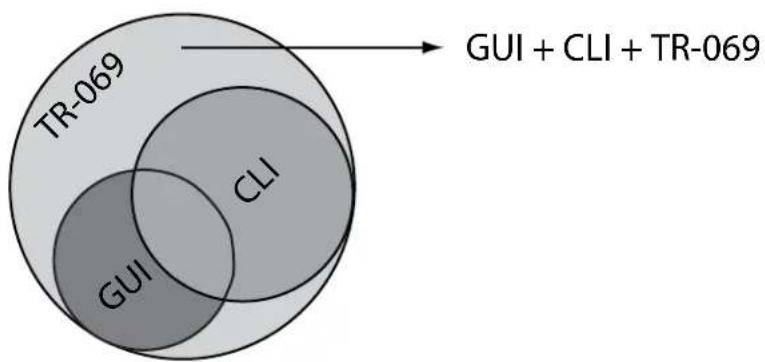
other
| Category | Value | | -------- | ----- | | TR-069 | | | CLI | | | GUI | |FIGURE 1-1 Scope of Functions for Management Interfaces
I.1.4 The Command Interface (CLI)
I.1.4.1 Getting Help
The following kinds of command help are available:
- lists of valid parameters with brief descriptions (the ? key)
• completion of keywords (the Tab key)
• error messages for incomplete or incorrect syntax
I.1.4.2 Command Abbreviations
The AlliedWare Plus CLI contains a number of abbreviations for its commands. For example, the show interface command can be entered in the abbreviated form shown below:
Table I-1: Common Abbreviations
| sh in vlan100show interface vlan100 |
| config termconfigure terminal. |
I.1.4.3 Viewing a List of Valid Parameters
To get syntax help, type ? (i.e. "space question mark") after:
- the prompt. This will list all commands available in the mode you are in.
- one or more parameters. This will list parameters that can come next in the partial command.
- one or more letters of a parameter. This will list matching parameters.
Note: The AlliedWare Plus CLI only displays one screenful of text at a time, with the prompt "--More--" at the end of each screenful. Press the space bar to display the next screenful or the Q key to return to the command prompt.
I.1.4.4 Example
To see which commands are available in Privileged Exec Mode, enter ? at the Privileged Exec Mode command prompt:
This results in the following output
awplus# ?
clear Reset functions
configure Enter configuration mode
copy Copy from one file to another
debug Allow debugging commands
delete Delete a file
dir List the files on a filesystem
disable Turn off privileged mode command
echo Echo a string on the Command Line
enable Turn on privileged mode command
erase Erase the system startup configuration
exit End current mode and down to previous mode
help Description of the interactive help system
move Rename or move a file
ping Send echo messages
reboot Halt and perform a cold restart
reload Halt and perform a cold restart
show Show platform global settings or self-test results
swupdate Software update
terminal Configure the terminal
test Configure test task parameters
traceroute Show the route packets take to network host
write Write running configuration to memory, file or terminal
To see which commands are available in Configuration mode, enter ? at the Config mode command prompt:
This results in the following output:
awplus# configure
Enter configuration commands, one per line. End with CNTL/Z.
awplus(config)# ?
access-list Create an access list
boot Boot configuration
clock Manage clock
debug Set application log output level
dial-peer Dial peer configuration parameters
do To run exec commands in config mode
enable Modify enable password parameters
end End current mode and down to privileged mode
exit End current mode and down to previous mode
help Description of the interactive help system
hostname Set system's network name
interface Select an interface to configure
ip Internet Protocol (IP)
ipv6 Internet Protocol version 6 (IPv6)
line Configure a terminal line
log Logging control
mac MAC and MAC address table configuration
mgcp Enter MGCP protocol configuration mode
mls Multi-Layer Switch(L2/L3)
no Negate a command or set its defaults
ntp Configure NTP
platform Platform commands
quit Quit
service Modify use of network based services
sip-ua Enter SIP User Agent configuration mode
snmp-server Enable the snmp agent
swupdate Software update
tr69-client Configure TR69 client
username Establish User Name Authentication
vlan Configure VLAN parameters
voice Voice configuration
voice-port Enter voice port configuration mode
Setting up the Gateway Getting Started
voipapp VoIP application configuration parameters
To see which show commands that start with "i" are available in Privileged Exec Mode, enter ? after show i:
awplus# show i ?
This results in the following output:
interface
ip
Select an interface to configure
Internet Protocol (IP)
I.1.4.5 Examples (clock timezone command)
To use the ? help to work out the syntax for the clock timezone command, enter the following sequence of commands:
The ? help only indicates what you can type next. For commands that have a series of parameters, the help guides the user for the next parameter, and does not indicate the number of parameters needed to complete the command.
I.1.4.6 Completing Keywords
To complete keywords, type the Tab key after part of the command.
If only one keyword matches the partial command, the AlliedWare Plus CLI fills in that keyword. If multiple keywords match, it lists them.
I.1.4.7 Examples
In this example we use Tab completion in successive steps to build the complete command show ip dhcp server summary. We have included
awplus# show ip
interface IP interface status and configuration
name-server Show DNS server IP address
route IP routing table
I.1.4.8 Moving the Cursor around Input Text (Home and End Keys)
The Home and End keys allow the user to go to the beginning or end of a command line, where new text can be inserted.
I.1.4.9 Viewing Command Error Messages
The switch displays the following generic error messages about command input:
% Incomplete command—this message indicates that the command requires more parameters. Use the ? help to find out what other parameters are available.
awplus# interface
% Incomplete command.
% Invalid input detected at '^' marker—this indicates that the switch could not process the command you entered. The switch also prints the command and marks the first invalid character by putting a '^' under it. Note that you may get this error if you enter a command in the wrong mode, as the following output shows.
awplus# interface port1.0.1
interface port1.0.1 ^ % Invalid input detected at '^' marker.
% Unrecognized command—when you try to use? help and get this message, it indicates that the switch can not provide help on the command because it does not recognize it. This means the command does not exist, or that you have entered it in the wrong mode, as the following output shows.
Note: The AlliedWare Plus iMG does not tell you when commands are successful. If it does not display an error message, you can assume the command was successful.
awplus# interface ?
% Unrecognized command
1.1.5 How to Work with Command Modes
The following figure shows the command mode hierarchy and the commands you use to move to lower-level modes.
Multiple users can telnet and issue commands using the User Exec mode and the Privileged Exec Mode. However, only one user is allowed to use the Configure mode at a time. This prevents multiple users from issuing configuration commands simultaneously.
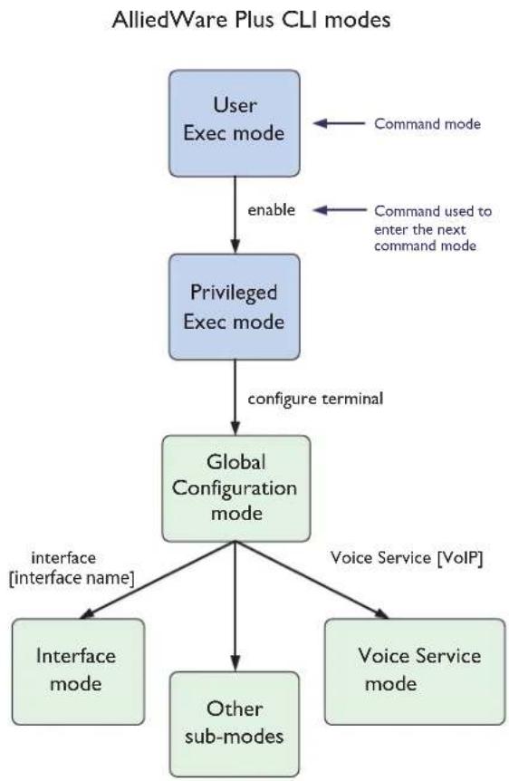
flowchart
graph TD
    A["User Exec mode"] -->|enable| B["Privileged Exec mode"]
    B -->|configure terminal| C["Global Configuration mode"]
    C -->|interface["interface name"]| D["Interface mode"]
    C -->|voice_Service["VoIP"]| E["Voice Service mode"]
    C --> F["Other sub-modes"]
    A <-->|Command mode| A
    B <-->|Command used to enter the next command mode| B
FIGURE 1-2 AlliedWare Plus CLI modes
I.1.5.1 User Exec mode
User Exec mode is the mode you log into on the switch.
It lets you perform high-level diagnostics (show commands, ping, traceroute etc), start sessions (Telnet, SSH), and change mode.
The default User Exec mode prompt is awplus>.
I.1.5.2 Privileged Exec Mode
To change from User Exec to Privileged Exec Mode, enter the command:
awplus># enable
Privileged Exec Mode is the main mode for monitoring—for example, running show commands and debugging. From Privileged Exec Mode, you can do all the commands from User Exec mode plus many system commands.
The default Privileged Exec Mode prompt is awplus#.
I.1.5.3 Global Configuration mode
To change from Privileged Exec to Global Configuration mode, enter the command:
awplus# configure terminal
From Global Configuration mode, you can configure most aspects of the switch.
The default Global Configuration mode prompt is awplus(config)#.
I.1.5.4 Lower-level configuration modes
A number of features are configured by entering a lower-level mode from Global Configuration mode. The following table lists these features.
Table I-2: Features configured using the lower level modes
| Mode What it configures | Command to access Default prompt | ||
| Interface Switch ports, VLANs, wireless interface, the management Eth port. | interfaceawplus (config-if)# | ||
| Line Console port settings or virtual terminal settings for telnet. | line console 0line vty number | awplus (config-line)# | |
| Voice Service These are general voice service configuration parameters. Some examples of related data are:- TMF Relay Configuration- RTP QOS Settings- RTCP Enabling/Disabling | voice service voipawplus (config-voi-srv)# | ||
| This level enables and disables the MGCP protocol service, as well as the links between MGCP and the IP network. | mgcp (from config-voi-srv level) | awplus (config-serv-mgcp)# | |
| This level enables and disables the SIP protocol service, as well as the links between SIP and the IP network | sip (from config-voi-srv level) | awplus (config-serv-sip)# | |
| MGCP Configuration that is specific to the MGCP Protocol Service including protocol specific information (timers etc) and references to the Call Agent. | mgcp (from config level) | awplus (config-mgcp)# | |
| SIP Configuration that is specific to the SIP Protocol Service including protocol specific information (timers etc) and references to the Location Server and Proxy Server. | sip-ua (from config level) | awplus (config-sip-ua)# | |
| Voice Applications (access codes) | Allows specification of the access codes required to enable, disable and program different supplementary services | voipapp feature access code | awplus (config-voiapp-fac)# |
Table I-2: Features configured using the lower level modes
| Mode | What it configures | Command to access | Default prompt |
| Voice Supplementary Services | Allows the enabling of a specific supplementary service on a per port basis – as well as configuration of port specific data – such as forwarded to DN. | voipapp supplementary services | awplus (config-voiapp-supl-serv-port) # |
| Voice Port This level enables the configuration of endpoint specific data such as gains etc | voice-port tel1/tel2 | awplus (config-voiceport) # | |
| Voice Class This level enables the definition of a set of Codecs – that are then associated with the appropriate Voiceport – thus enabling a fixed set of codecs for that line | voice class codec | awplus (config-voice-class) # | |
| Dial Peer This can be viewed as an addressable endpoint. As such there are really two different varieties of the dial-peer – the incoming dial-peer – against which information is configured that is required to terminate to an associated voiceport – including for example DN – and the outgoing dial-peer – against which information is configured – that enables the system to route a call to an external callagent or softswitch. Especially important here are the destination pattern (or digit map). Note that three dial peers are created automatically when the system is created – dial peer 1 and 2 are incoming dial-peers – and are associated with voice ports tel1 and tel2 respectively. Dial peer 3 is the out-going dial-peer and is only activated when SIP is enabled. | dial peer voice | awplus (config-dial-peer) # | |
| VLAN database VLANs. vlan database awplus (config-vlan) # | |||
| DHCP dhcp server pools and attributes ip dhcp pool (from | config-if access) | awplus (dhcp-config) # | |
| SSID For configuration of global SSIDs. dot11 ssid <ssid-name> | awplus (config-if-ssid) # | ||
| 2.4GHz 802.11 radio | For configuration of 2.4GHz 802.11 radio. | interface dot11radio1.0.1 | awplus (config-if-dot11radio) # |
I.1.5.5 Returning to higher-level modes
The following figure shows the commands to use to move from a lower-level mode to a higher-level mode.
AlliedWare Plus CLI modes - returning to higher-level modes
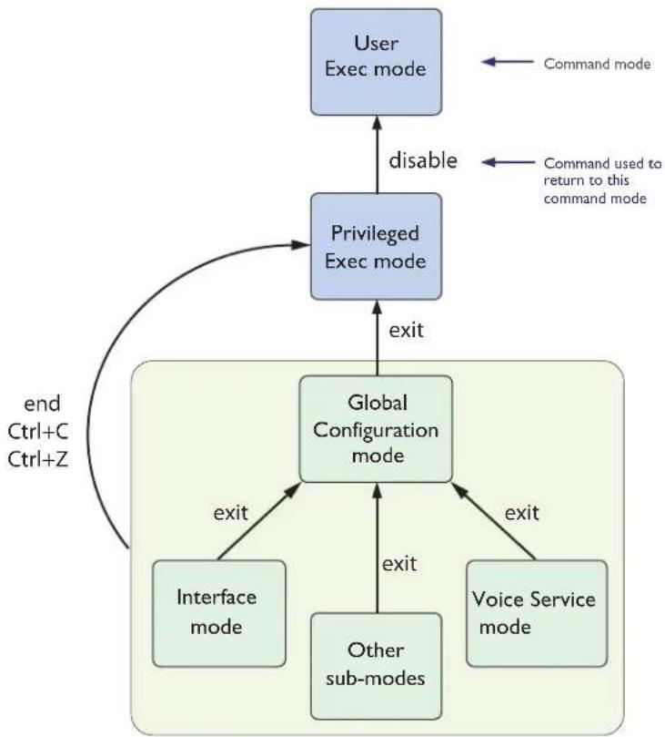
flowchart
graph TD
    A["User Exec mode"] -->|disable| B["Privileged Exec mode"]
    B -->|exit| C["Global Configuration mode"]
    C -->|exit| D["Interface mode"]
    C -->|exit| E["Voice Service mode"]
    C -->|exit| F["Other sub-modes"]
    C -->|end Ctrl+C Ctrl+Z| G["End"]
    style A fill:#cce5ff,stroke:#333
    style B fill:#cce5ff,stroke:#333
    style C fill:#cce5ff,stroke:#333
    style D fill:#cce5ff,stroke:#333
    style E fill:#cce5ff,stroke:#333
    style F fill:#cce5ff,stroke:#333
    style G fill:#cce5ff,stroke:#333
FIGURE 1-3 Returning to higher-level modes
I.1.5.6 Examples
To go from Interface Configuration to Global Configuration mode:
awplus(config-if)# exit
awplus(config)#
To go from Interface Configuration to Privileged Exec Mode:
awplus(config-if)# end
awplus#
To go from Privileged Exec to User Exec (the equivalent to log out):
awplus# disable
awplus
I.1.5.7 Entering Privileged Exec Commands When in a Configuration Mode
As you configure the switch you will be constantly entering various show commands to confirm your configuration. This requires constantly changing between configuration modes and Privileged Exec Mode.
However, you can run Privileged Exec commands without changing mode, by using the command:
do
You can use the ? help to find out command syntax when using the do command.
To display information about the IP interfaces when in Global Configuration mode, enter the command:
This results in the following output:
awplus(config)# do show ip int
| Interface |
| vlan1 |
| vlan2 |
| IP-Addressunassignedunassigned |
| Status |
| admin up |
| admin up |
| Protocol running running |
I.1.5.8 Main Command Modes Summary
The table below lists the main command modes, how to access each mode, the prompt for each command mode. From any mode, use exit to move up a mode, or end to move to the Privileged Exec Mode.
Table I-3: Main command modes and modal prompts
| Present Mode Prompt | Command New Mode | ||
| User Exec | awplus# | enable | Privileged Exec |
| Privileged Exec | awplus# | configure terminal | Global Configuration |
| Global Configuration | awplus(config)# | vlan database | VLAN Configuration |
I.1.6 How to See the Current Configuration (running-config)
The current configuration is called the running-config. To see it, enter the following command in either Privileged Exec Mode or any configuration mode:
awplus# show running-config
Note: The database for the configuration is an xml object model.
I.1.7 Default Settings
When the switch first starts up with the AlliedWare Plus CLI, it applies default settings and copies these defaults dynamically into its running-config.
These default settings mean that the AlliedWare CLI:
- encrypts passwords, such as user passwords
• records log message priority in log messages
• turns on the telnet server so that you can telnet to the switch -
enables the switch to look up domain names (but for domain name lookups to work, you have to configure a DNS server)
• starts up in default L2 bridging mode. -
sets all the switch ports to access mode. This means they are untagged ports, suitable for connecting to hosts
- creates untagged VLAN I and adds all the switch ports to it
- allows logins on VTY sessions (for telnet etc)
- has switching enabled, so layer 2 traffic is forwarded appropriately without further configuration
- has ports set to autonegotiate their speed and duplex mode
• has copper ports set to auto MDI/MDI-X mode - disables flow control on WAN, but enables it on LAN interfaces.
I.1.8 The Default Configuration
This includes most of the above default settings, which the switch copies to its running-config when it first boots up.
The switch stores a copy of the default configuration in the file, default.cfg and uses this as its default start-up file.
For more information about start-up files, see 1.1.11.
I.1.9 Defining a User/Password
To change the password for an account, the username is deleted and then re-created. This applies to the default user (manager) as well.
awplus(config)# username <user> privilege <level> password <password>
The password can be up to 23 characters in length and include characters from up to four categories. The password categories are:
• uppercase letters: A to Z
- lowercase letters: a to z
- digits: 0 to 9
- special symbols: all printable ASCII characters not included in the previous three categories. The question mark ? cannot be used as it is reserved for help functionality.
I.I.10 How to Set an IP Address on VLAN I
This section describes how to set an IP address on the default VLAN (vlan1).
- If desired, check the current configuration
After logging in, enter Privileged Exec Mode by using the command:
awplus# enable (Privileged Exec Mode)
Then check the current configuration by using one of the following commands:
awplus# show ip interface brief
This results in the following output:
Interface vlan1
IP-Address 172.28.8.200
Status admin up
Protocol running
- Enter Interface Configuration mode for the vlan I interface
Enter Global Configuration mode and enter the command:
awplus(config)# interface vlan1
3. Enter the IP address and mask
Enter the command:
awplus(config-if)# ip address
For example, to set the address to 172.28.8.210/16, enter the command:
awplus(config-if)# ip address 172.28.8.210/16
I.I.II How to Save and Boot from the Current Configuration
This section tells you how to save your configuration and run the saved configuration when the switch starts up.
Refer to Figure 1-4, which shows the basic software file configuration. This figure is used to help describe a number of software configuration scenarios.
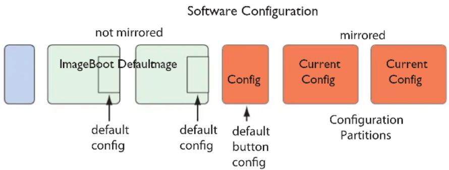
flowchart
graph LR
    A["ImageBoot"] --> B["Default config"]
    C["Image"] --> D["Default config"]
    E["Config"] --> F["default button config"]
    G["Current Config"] --> H["Configuration Partitions"]
    I["Current Config"] --> H
    style A fill:#4A90E2,stroke:#333
    style C fill:#4A90E2,stroke:#333
    style E fill:#FFB6C1,stroke:#333
    style G fill:#FFB6C1,stroke:#333
    style I fill:#FFB6C1,stroke:#333
    style B fill:#B2C5F2,stroke:#333
    style D fill:#B2C5F2,stroke:#333
    style F fill:#FFB6C1,stroke:#333
    style H fill:#FFB6C1,stroke:#333
FIGURE 1-4 Basic Software Configuration
Table I-4: Components of Software Configuration
| Area Purpose Notes | ||
| Configuration Partitions (Mirrored) | All user configuration files are stored here (i.e. all configurations except default.cfg and default_button.cfg). Whenever a user configuration is changed, the oldest configuration partition is brought up to date with the other one and then the new changes are saved to it. In other words configuration saves, copies, and deletions are made to alternate configuration partitions.Therefore, if for some reason an error occurs, the other partition contains a known good backup point. | |
| Default Button Partition This | partition contains a configuration that can be used to override the default.cfg. configuration. This enables the service provider to define a baseline configuration that can be recovered for the device if something goes wrong while manipulating the user configurations (or if the user configurations are removed). | It possible to copy a custom configuration into default_button.cfg |
Table I-4: Components of Software Configuration
| Area Purpose Notes | ||
| Image Partition (1 and 2) Partition 1 contains one complete executable image plus the default.cfg that is guaranteed to be compatible with this image.Partition 2 contains one complete executable image plus the default.cfg that is guaranteed to be compatible with this image | The default.cfg file is provided with the device with specific attributes; therefore, default.cfg cannot be created, moved, or modified from the CLI. Note that the file cannot be deleted. Note that iMGI400 family supports only one image partition. | |
| Boot Partition This partition contains the bootloader plus device specific configuration parameters – such as Serial Number and MAC Address. This partition is not accessible from the firmware. | ||
| PSP Partition This small partition contains information required to ensure that the system loads the desired image and configuration. It can be modified via CLI commands. | ||
| startup-config A shortcut that represents the current boot configuration file. At startup, this is the default.cfg. You can then change the startup-config so that it does not contain the default.cfg (default.cfg is read-only). | Note that the file can be deleted, with the ‘force’ option. Refer to “delete” | |
| running-config A shortcut that represents the current running configuration file. You can you can save this configuration as the startup-config so it will be used when starting up. | ||
I.I.II.I How to Save the Running Configuration to the current boot file (startup-config)
Enter Privileged Exec Mode and enter the command:
awplus# copy running-config startup-config
Note: If the running configuration is default.cfg, the startup-config must first be specified with an alternate filename for this to work as default.cfg is a read-only configuration which cannot be modified or deleted.
I.I.11.2 How to Create and Use a New Configuration File
- Copy the current configuration to a new file
Enter Privileged Exec Mode and enter the command:
awplus# copy running-config
I.I.I1.3 Example
To save the current configuration in a file called customer_a.cfg, enter the command
awplus# copy running-config customer_a.cfg
- Set the switch to use the new file at startup
To run the new file's configuration when the switch starts up, enter Global Configuration mode and enter the command:
awplus(config)# boot config-file customer_a.cfg
Note: If customer_a.cfg does not exist it will be created using a copy of the running-config.
For an explanation of the configuration fallback order, see "The configuration file fallback order".
I.I.11.4 Example
To run the commands in example.cfg on startup, enter the command:
awplus(config)# boot config-file customer_a.cfg
Display the new settings
To see the files that the switch uses at startup, enter Privileged Exec Mode and enter the command:
awplus# show boot
The output looks like this:
Boot configuration
Current software : [partition 1] bcm96368GW_fs_kernel.AtiBcm-4.1_20
Current boot image : [partition 1] bcm96368GW_fs_kernel.AtiBcm-4.1_20
Backup boot image : [partition 2] bcm96368GW_fs_kernel.AtiBcm-4.1_20
Default boot config: default.cfg
Backup boot config: default_button.cfg (file exists)
Current boot config: customer_a.cfg (file exists)
Continue updating the file when you change the configuration
When you next want to save the current configuration, enter Privileged Exec Mode and enter the command:
awplus# copy running-config startup-config
I.1.12 How to Return to the Factory Defaults
The switch dynamically adds the default settings to the running-config at start-up if the current boot configuration file is not present. This section describes how to use this feature to return to the factory defaults.
Note: After reboot the show running-config output will show the default factory settings for your switch.
Refer to Start-up Sequence for more information on how the device boots up in various scenarios.
1.1.12.1 Completely restore defaults
To completely remove your configuration and return to the factory default configuration, delete or rename the current boot configuration file and make sure no other file is set as the start-up configuration file.
To find the location of the default boot configuration file, enter Privileged Exec Mode and enter the command:
awplus# show boot
To delete the current boot configuration, enter Privileged Exec Mode and enter either of the commands:
awplus# delete force <filename>
or:
awplus# erase startup-config
Note: The wildcard character '*' is supported, and Configuration files must end with '.cfg', so delete *.cfg will delete all config files (except default.cfg). Also note that erasing startup-config deletes the current boot configuration file; it does not simply stop the file from being the boot file.
To make sure that no other file is loaded at start-up, enter Global Configuration mode and enter the command:
awplus(config)# no boot config-file
This will set 'default_button.cfg' as the startup-config.
I.I.13 Recovery of Single Image (iMG1400)
Since the 1400 is a single image based device (unlike the 1500/2500 devices), if the primary image fails, there is no emergency recovery image available, and so an alternate image needs to be available to bring the board into service so that it can be repaired if necessary. This is done using the following:
- In the event of primary image failure, the iMG can perform a netboot (from a TFTP server).
- The default file name requested in the netboot defaults to a well known filename (the image name from the 4.2 GM release)
- The default TFTP server from which the file should be loaded is the one allocated by the DHCP server.
- The default CRC which is used to validate the incoming file is stored in UB and by default is the CRC of the initial release supporting this device.
-
The user can override the following through the application program
-
TFTP filename
- TFTP server
-
TFTP CRC
-
Only CRC validated files will be loaded via netboot during recovery
• CRC can be disabled from the user application
I.I.14 How to See System Information
This section describes how to view the following system information:
• overview information
- serial number
I.I.14.1 Viewing Overall System Information
To display an overview of the switch hardware, software, and system settings, enter User Exec or Privileged Exec Mode and enter the command:
awplus# show system
The output looks like this:
Setting up the Gateway Getting Started
awplus> show system
Switch System Status Mon Jan 12 12:48:31 1970
Board ID Bay Board Name Rev Serial Number
Base iMG2504 X1 ATNLAB0000001
Memory: DRAM: 125012 kB Used: 69872 kB Available: 55140 kB
Environmental Status : Normal
Uptime : 11 days 12:48:32
Bootloader version : AtiUboot-1.0_07
VoIP version : AtiVoip-2.2_32
Current Software : AT-iMG2500-4.2_60
Software version : AtiBcm-4.2_60 ALPHA
Build date : 00:30 14/06/12
Current boot config : customer_sip.cfg (file exists)
Territory :
System Name :
System Contact :
System Location :
I.I.15 How to Set System Parameters
You can set system parameters to personalize the switch and make it easy to identify it when troubleshooting. This section describes how to configure the following system parameters:
• telnet session timeout
- switch name
I.I.15.1 How to Change the Telnet Session Timeout
By default, telnet sessions time out after 10 minutes of idle time. If desired, you can change this.
I.1.15.2 Examples
To set the timeout to 30 minutes, enter the command:
awplus(config-line)# exec-timeout 30
I.I.15.3 How to Name the Device
To give the device a name, enter Global Configuration mode and enter the command:
awplus(config)# hostname <name>
For example, to name the switch "switch1.mycompany.com":
awplus(config)# hostname switch1.mycompany.com
The prompt displays the new name:
switch1.mycompany.com(config)#
The name can contain hyphens, dots, and underscore characters.
However, the name must be a single word, as the following example shows.
awplus(config)#hostname switch1.mycompany.com more words
hostname switch1.mycompany.com more words
% Invalid input detected at '^' marker.
It also cannot be surrounded by quote marks, as the following example shows.
awplus(config)#hostname "switch1.mycompany.com more words"
% Please specify string starting with alphabet
Also, the prompt has a fixed maximum length, and so the host name in some cases may be truncated. Refer to hostname.
I.1.15.4 Removing the name
To remove the hostname, enter the command:
switch1.mycompany.com(config)# no hostname
The prompt changes back to the default prompt:
awplus(config)#
I.I.16 How to Set the Time and Date
There are three aspects to setting the time and date:
- setting the current time and date.
- setting the timezone
- configuring the switch to automatically change the time when summer-time begins and ends.
Note: Instead of manually setting the time, you can use NTP to automatically get the time from another device. Refer to Network Time Protocol (NTP).
I.I.16.1 How to Show Current Settings
To display the current time, timezone and date, enter Privileged Exec Mode and enter the command:
awplus# show clock
The output looks like this:
Local Time: Fri, 02 Jan 1970 18:57:48 -08:00
UTC Time: Sat, 03 Jan 1970 02:57:48 +00:00
Timezone: PST
Timezone name: Pacific time, Tijuana
Timezone offset: -08:00
Summer time: disabled
I.I.16.2 How to Set the Time and Date
To set the time and date, enter Privileged Exec Mode and enter the clock set command clock set:
clock set <hh:mm> <day> <month> <year>
where:
- hh is two digits giving the hours in 24-hour format (e.g. 14)
• mm is two digits giving the minutes
• day is two digits giving the day of the month - month is the first three letters of the month name (e.g. Sep) - The first letter must be capitalized.
• year is four digits giving the year
Note: The setting of seconds is not supported.
To set the time to 14:00:00 on 25 January 2012, use the command:
awplus(config)# clock set 14:00 25 Jan 2012
I.1.16.3 How to Set the Timezone
To set the timezone, enter Global Configuration mode and enter the clock timezone command clock timezone:
clock timezone <timezone-name>
The
To return the timezone to UTC+0, enter the command:
awplus(config)# no clock timezone
To set the timezone to New Zealand Standard Time, use the command:
awplus(config)# clock timezone NZST
I.I.16.4 How to Configure Summer-time
To enable summer-time management, use the command clock summer-time:
The summer time will be managed automatically, depending on the time zone, without specifying any start or stop date and time.
To disable summer time management, use no clock summer-time
I.1.16.5 How to Configure Summer-time
To configure summer-time, use the following:
awplus(config)# clock summer-time
I.I.17 How to Add and Remove Users
I.I.17.1 Adding users
To add a new user with administrative rights, enter Global Configuration mode and enter the command:
awplus(config)# username <name> privilege 15 password <password>
Both
The AlliedWare Plus CLI gives you a choice of 1 or 15 for the privilege level. Level 1 users are limited to User Exec mode so you need to set most users to level 15.
For example, to add user Bob with password 123\$%^, enter the command:
awplus(config)# username Bob privilege 15 password 123$%^
I.1.17.2 Removing users
To remove a user, enter Global Configuration mode and enter the command:
no username <name>
For example, to remove user Bob, enter the command:
awplus(config)# no username Bob
Note that you can delete all users, including the user called "manager" and the user you are logged in as. If all privilege 15 user accounts are deleted, a warning message is generated:
% Warning: No privileged users exist.
Note: If all privilege level 15 user accounts are deleted, and there are no other users configured for the device, manager/friend is automatically created.
If there is a user account on the device with a lower privilege level and a password has already been set with the enable password command, you can log in and still enter privileged mode. When executing the enable command, enter the password created with the enable password command. For example, if the password is mypassword:
awplus> enable mypassword
awplus#
I.1.17.3 Displaying users
To list all configured users, enter User Exec or Privileged Exec Mode and enter the command:
awplus# show security-password user
The output looks like this:
Username Privilege
manager 15
alice 15
guest 1
I.1.18 How to Undo Settings and Restore Parameters to Defaults (no option)
Using the no parameter can accomplish both of these tasks.
To undo most settings, simply re-enter the first parameters of the configuration command with the parameter no before them.
You can set the timezone to Eastern Standard Time by entering the command:
awplus(config)# clock timezone EST-USA
To remove the timezone setting, enter the command:
awplus(config)# no clock timezone
I.1.19 How to Upgrade the Firmware
New releases of the AlliedWare Plus CLI become available regularly. Contact your customer support representative for more information.
- Put the new release onto your TFTP server. (The iMG software must be extracted from the zipped file).
Note: You can use the GUI of the browser to upgrade the firmware, using the Computer Management tab. Refer to Using the GUI Application for more information on the web-based GUI. The iMG software must be extracted from the zipped file prior to upgrade via webGUI.
- Copy the new release from your TFTP server onto a switch partition (not the one that will be booted from).
awplus(config)# copy tftp://<tftp server address>/<path><filename><filename>
- Upon successful copy of a firmware upgrade onto the iMG, the new firmware will automatically be marked as bootable.
Note: The other partition is deliberately not loaded with the new release, in case the new load is bad.
- Check the boot settings
Enter Privileged Exec Mode and enter the command:
awplus# show boot
- Reboot
Enter Privileged Exec Mode and enter this command and respond to the prompt:
awplus# reload
reboot system? (y/n):
I.1.20 How to configure Wireless
Wireless configuration is a three-step procedure:
- First the desired VLAN must be associated with the SSID
awplus# configure
Enter configuration commands, one per line. End with CNTL/Z.
awplus(config)# vlan
awplus(config-vlan)# vlan 2
awplus(config-vlan)# exit
awplus(config)# do show dotll bssid
Interface BSSID Guest SSID VLAN
dot11radio1.0.1 e2:0c:25:00:01:6d Yes iMG1425W_00_01_6d Default
dot11radio1.0.1 Guest1
Setting up the Gateway Getting Started
dot11radiol.0.1 Guest2
dot11radiol.0.1 Guest3
awplus(config)# dot11 ssid iMG1425W_00_01_6d
awplus(config-if-ssid)# vlan 2
awplus(config-if-ssid)# exit
awplus(config)# exit
awplus#
Note: An SSID may be associated with at most one VLAN at a time. If an SSID is not associated with a VLAN it will not be shown on the web GUI.
- The remainder of the wireless configuration can now be completed using the web GUI.
- Ensure that wireless is enabled. The green wireless LED on the front of the iMG should be lit. If not, press the wireless multi-function button for 3 seconds to hardware-enable wireless. Note that this button acts as a toggle, enabling & disabling wireless (it overrides wireless enabling/disabling functionality available via the CLI & web GUI). Press the wireless button and wait a couple of seconds to enable it. For disabling the wireless function the button needs to be pressed for a longer time (at least 7 seconds).
1.1.21 Commands Available in each Mode
This appendix lists the commands available in the following command modes:
- User Exec Mode
- Privileged Exec Mode
• Global Configuration Mode
I.1.21.1 User Exec Mode
awplus> ?
clear Reset functions
disable Turn off privileged mode command
enable Turn on privileged mode command
exit End current mode and down to previous mode
help Description of the interactive help system
logout Exit from the EXEC
show Show running system information
I.1.21.2 Privileged Exec Mode
awplus# ?
clear Reset functions
configure Enter configuration mode
copy Copy from one file to another
debug Allow debugging commands
delete Delete a file
dir List the files on a filesystem
disable Turn off privileged mode command
enable Turn on privileged mode command
erase Erase the system startup configuration
exit End current mode and down to previous mode
help Description of the interactive help system
move Rename or move a file
ping Send echo messages
reboot Halt and perform a cold restart
reload Halt and perform a cold restart
show Show platform global settings or self-test results
swupdate Software update
terminal Configure the terminal
traceroute Show the route packets take to network host
write Write running configuration to memory, file or terminal
I.1.21.3 Global Configuration Mode
awplus(config)# ?
access-list Create an access list
boot Boot configuration
clock Manage clock
debug Set application log output level
dial-peer Dial peer configuration parameters
do To run exec commands in config mode
enable Modify enable password parameters
end End current mode and down to privileged mode
exit End current mode and down to previous mode
help Description of the interactive help system
hostname Set system's network name
interface Select an interface to configure
ip Internet Protocol (IP)
ipv6 Internet Protocol version 6 (IPv6)
line Configure a terminal line
log Logging control
mac MAC and MAC address table configuration
mgcp Enter MGCP protocol configuration mode
mls Multi-Layer Switch(L2/L3)
no Negate a command or set its defaults
ntp Configure NTP
platform Platform commands
quit Quit
service Modify use of network based services
sip-ua Enter SIP User Agent configuration mode
snmp-server Enable the snmp agent
swupdate Software update
tr69-client Configure TR69 client
username Establish User Name Authentication
vlan Configure VLAN parameters
voice Voice configuration
voice-port Enter voice port configuration mode
voipapp VoIP application configuration parameters
I.2 Command Syntax Conventions in this Software Reference
The following table describes how command line interface syntax is shown in this Software Reference.
Table I-5: Syntax Conventions
| Syntax element Example What to enter in the command line | ||
| Keywords are shown in lowercase fixed-width font or bold variable-width font | show memory historyorshow ip route | Some keywords are required, and others are optional parameters. Type keywords exactly as they appear in the command syntax. |
| Number ranges are enclosed in angle-brackets <> and separated by a hyphen. | <0-255> | Enter a number from the range. Do not enter the angle brackets. |
Table I-5: Syntax Conventions
| Placeholders are shown in lowercase italics within angle-brackets < >, or in uppercase italics | Replace the placeholder with the value you require. The place holder may be an IP address, a text string, or some other value. See the parameter table for the command for information about the type of value to enter.Do not enter the angle-brackets. | |
| Repeats are shown with ellipsis. | param1... | Enter the parameter one or more times. |
| Optional elements are shown in brackets: [ ] | vlan[name] | If you need the optional parameter, enter it. Do not enter the brackets. |
| Required choices are enclosed in braces and separated by a vertical bar (pipe): {|.} | show{|} | Enter one only of the options.Do not enter the braces or vertical bar. |
| Optional choices are enclosed in or brackets and separated by a vertical bar (pipe): [|] | [param1|param2] | If needed, enter one only of the options.Do not enter the brackets or vertical bar. |
| Inclusive options are enclosed in braces, and separated by brackets:{{[][]}. | {[param1][param2][param3]} | Enter one or more of the options and separate them with a space.Do not enter the braces or brackets. |
1.3 Start-up Sequence
The start-up sequence for a device running AT-iMG software under normal circumstances will be as seen below - this sequence will be seen when everything loads and runs as expected.
Booting up consists of three major operations:
I. Image and configuration Selection
- As the device begins to boot, the bootloader reads the contents of the PSP flash partition which stores the preferred partition to load the image from (partition 1 or partition 2) and the preferred configuration to load. If for some reason the psp is corrupt – or unreadable, the bootloader will always begin the process by attempting to load the image from partition 1 and the default.cfg configuration.
- The boot loader checks to determine whether or not the previous boot process has succeeded. (There is a window of 300 seconds at which a boot process is qualified as a success). If it did not, then the bootloader begins the process with the other partition.
- The bootloader checks to determine that the image is present and valid (e.g. not corrupt). If the image is corrupt, it begins the process with the other partition.
-
The bootloader looks to determine if the reset button has been pressed. If it has been pressed, then the bootloader discards any preferred configuration specified, and uses the default_button.cfg if present (customer default), or default.cfg (generic default).
-
Image Loading
-
The bootloader then loads the selected image.
- Once the image has loaded, the Application notes that it successfully booted. (There is a window of 300 seconds.)
Setting up the Gateway CLI Navigation Commands
- If the image boot process fails and the device resets (using for example the watchdog function), then the bootloader will know to use the other image.
- Configuration Loading
- Once the application image has successfully loaded, then configuration loading process begins.
- The device verifies that the selected configuration is acceptable. This implies that:
- The configuration is valid and compatible with the image.
- Unknown objects are ignored, and unknown attributes are discarded.
• If the above test fails, then: - if the default_button.cfg exists, it is chosen as the selected configuration and the process is repeated.
- If the default_button.cfg does not exist – or is not valid and compatible, then the default.cfg is chosen as the selected configuration and the process is repeated. The default.cfg will always be valid and compatible since it is delivered with the Application image.
- The device then begins to load the configuration
- If there is a failure during the configuration loading process – or up to 300 seconds after that process started, then it is assumed that the configuration is not valid – and the fallback configuration is specified as the preferred configuration to load – and the device restarts.
- Once the configuration is loaded, and 300 seconds has expired, the application notes that it successfully loaded.
Note: The 300 second time period is configurable.
I.4 CLI Navigation Commands
This chapter provides an alphabetical reference for the commands used to navigate between different modes. This chapter also provides a reference for the help and show commands used to help navigate within the CLI.
Note: The up-arrow and down-arrow keys can also be used to scroll back and forth through previous commands.
1.4.1 CLI Navigation Commands
Table I-6: CLI Navigation Commands
| Commands |
| configure terminal |
| disable (Privileged Exec Mode) |
| do |
| enable (Privileged Exec Mode) |
| end |
| exit |
| help |
| logout |
| show history |
CONFIGURE TERMINAL
Syntax configure terminal
Description This command enters the Global Configuration command mode.
Feature CLI Navigation Commands
Mode Privileged Exec Mode
Release 4.1
Options NA
Note NA
Example To enter the Global Configuration command mode (note the change in the command prompt), enter the command:
awplus# configure terminal Enter configuration commands, one per line. End with CNTL/Z. awplus(config)#
Setting up the Gateway CLI Navigation Commands
DISABLE (PRIVILEGED EXEC MODE)
Syntax disable
Description This command exits the Privileged Exec Mode, returning the prompt to the User Exec mode. To end a session, use the exit command.
Feature CLI Navigation Commands
Mode Privileged Exec Mode
Release 4.1
Options NA
Note NA
Example To exit the Privileged Exec Mode, enter the command:
awplus# disable
awplus>
DO
Syntax do
Description This command lets you to run User Exec and Privileged Exec Mode commands when you are in a Configuration mode.
Feature CLI Navigation Commands
Mode Any configuration mode
Release 4.1
Options
| Option Description Range | Default Value | ||
| Specify the command and its parameters. | NA | NA | |
Note NA
Example Here is an example of the do command:
awplus> enable
awplus# configure terminal
Enter configuration commands, one per line. End with CNTL/Z.
awplus(config)# do ping 192.168.200.1
PING 192.168.200.1 (192.168.200.1): 56 data bytes
56 bytes from 192.168.200.1: icmp_seq=0 ttl=64 time=0.7 ms
56 bytes from 192.168.200.1: icmp_seq=1 ttl=64 time=0.4 ms
56 bytes from 192.168.200.1: icmp_seq=2 ttl=64 time=0.4 ms
56 bytes from 192.168.200.1: icmp_seq=3 ttl=64 time=0.4 ms
--- 192.168.200.1 ping statistics ---
4 packets transmitted, 4 packets received, 0% packet loss
round-trip min/avg/max = 0.4/0.4/0.7 ms
awplus(config)#
Setting up the Gateway CLI Navigation Commands
ENABLE (PRIVILEGED EXEC MODE)
Syntax
enable
Description This command enters the Privileged Exec Mode.
Feature CLI Navigation Commands
Mode User Exec Mode
Release 4.1
Options NA
Note NA
Example The following example shows the use of the enable command to enter the Privileged Exec Mode (note the change in the command prompt)
awplus# enable awplus#
Setting up the Gateway CLI Navigation Commands
END
Syntax end
Description This command returns the prompt to the Privileged Exec command mode from any other advanced command mode.
Feature CLI Navigation Commands
Mode All command modes
Release 4.1
Options NA
Note NA
Example The following example shows the use of the end command to return to the Privileged Exec Mode directly from Interface mode.
awplus# enable
awplus# configure terminal
Enter configuration commands, one per line. End with CNTL/Z.
awplus(config)# interface vlanl
awplus(config-if)# end
awplus#
Setting up the Gateway CLI Navigation Commands
EXIT
Syntax exit
Description This command exits the current mode, and returns the prompt to the mode at the previous level. When used in User Exec mode, the exit command terminates the session.
Feature CLI Navigation Commands
Mode All command modes.
Release 4.1
Options NA
Note NA
Example The following example shows the use of exit command to exit Interface mode:
awplus(config-if)# end
awplus# exit
awplus#
AlliedWare Plus CLI has terminated. Have a nice day!!!
Connection to host lost.
Setting up the Gateway CLI Navigation Commands
HELP
Syntax help
Description This command displays a description of the AT-iMG CLI help system.
Feature NA
Mode All command modes
Release 4.1
Options NA
Note NA
Example To display a description on how to use the system help, use the command
awplus> enable
awplus# help
When you need help at the command line, press '?'.
If nothing matches, the help list will be empty. Delete characters until entering a '?' shows the available options.
Enter '?' after a complete parameter to show remaining valid command parameters (e.g. 'show ?').
Enter '?' after part of a parameter to show parameters that complete the typed letters (e.g. 'show ip?'). awplus#
Setting up the Gateway CLI Navigation Commands
LOGOUT
Syntax logout
Description This command exits the User Exec or Privileged Exec Modes and ends the session.
Feature CLI Navigation Commands
Mode User Exec Mode
Release 4.1
Options NA
Note NA
Example To exit the User Exec mode, use the command:
awplus> logout
awplus>
AlliedWare Plus CLI has terminated. Have a nice day!!!
SHOW HISTORY
Syntax show history
Description This command lists the commands entered in the current session. The history buffer is cleared automatically upon reboot. Also, note that identical commands entered consecutively appear as single entry.
The output lists all command line entries, including commands that returned an error.
Feature CLI Navigation Commands
Mode User Exec and Privileged Exec
Release 4.1.2
Options NA
Note In this release, an incomplete command that is entered does not show up in the command list.
Example To display the commands entered during the current session, use the command:
awplus# show history
awplus# show history
1 enable
2 config
3 show history
4 quit
5 show history
awplus#
1.5 User Access Commands
1.5.1 User Access Commands
This chapter provides an alphabetical reference of commands used to configure user access.
Table I-7: User Access Commands
| Commands |
| enable password |
| exec-timeout |
| service http |
| service ssh |
| service telnet |
| show exec-timeout |
| show exec-timeout |
| show http |
| show security-password user |
| show ssh |
| show ssh server |
| show telnet |
| terminal length |
| username |
ENABLE PASSWORD
Syntax
enable password
Description
This command sets a local password to control access to various privilege levels. Use the enable password command to modify or create a password to be used, and use the no enable password command to remove the password.
This also enables the Network Administrator to set a password for entering the enable mode. There are three methods to enable a password. In the examples below, for each method, the configuration is different: the configuration file output is different, but the password string to be used to enter the enable mode is the same (mypasswd).
A user can have an intermediate CLI security level set with this command for privilege level 7 to access all the show commands in Privileged Exec Mode and all the commands in User Exec mode, but not any configuration commands in Privileged Exec Mode.
Feature User Access Commands
Mode Global Configuration Mode
Release 4.1
Options
| Option Description Range | Default Value | ||
| the unencrypted password. NA NA | |||
Note
Do not use encrypted passwords for GUI users. The GUI requires unencrypted user passwords only - not encrypted user passwords. Do not use option 8 for GUI users.
Example The plain password is encrypted in the configuration files (part of xml attributes).
awplus# configure terminal
Enter configuration commands, one per line. End with CNTL/Z.
awplus(config)# enable password mypasswd
awplus(config)# end
EXEC-TIMEOUT
Syntax
exec-timeout {<minutes>}
no exec-timeout
Description
This command sets the interval your device waits for user input from either a console or VTY connection. Once the timeout interval is reached, the connection is dropped. This command sets the time limit when the console or VTY connection automatically logs off after no activity. The no variant of this command removes a specified timeout and resets to the default timeout (10 minutes). This command is used set the time the telnet session waits for an idle VTY session, before it times out. An exec-timeout 0 0 setting will cause the telnet session to wait indefinitely. The command exec-timeout 0 0 is useful while configuring a device, but reduces device security. If no input is detected during the interval then the current connection resumes. If no connections exist then the terminal returns to an idle state and disconnects incoming sessions..
Feature User Access Commands
Mode Line Configuration
Release 4.3.2
Options
| Option Description Range | Default Value | ||
| <minutes> Required integer timeout value in minutes <0-35791> 10 | |||
| <seconds> Required integer timeout value in seconds <0-2147483> 0 |
Note
When setting 0 minutes and 0 seconds the console session waits indefinitely
Example To set connections to timeout after 2 minutes and 30 seconds if there is no response from the user, use the following commands
awplus# configure terminal
awplus(config)# line console 0
awplus(config-line)# exec-timeout 2 30
Example To reset the console connection to the default timeout of 10 minutes if there is no response from the user, use the following commands:
awplus# configure terminal
awplus(config)# line console 0
awplus(config-line)# no exec-timeout
SERVICE HTTP
Syntax service http no service http
Description This command enables the HTTP (Hypertext Transfer Protocol) service. The HTTP service is enabled by default on a Java enabled browser.
The no service http command disables the HTTP feature.
The HTTP service is enabled by default.
Feature User Access Commands
Mode Global Configuration Mode
Release 4.1
Options NA
Note NA
Example To disable the HTTP service, use the command.
awplus> enable
awplus# configure terminal
Enter configuration commands, one per line. End with CNTL/Z.
awplus(config)# no service http
awplus(config)#
Example To re-enable the HTTP service, use the command.
awplus(config)# service http
awplus(config)#
SERVICE SSH
Syntax
service ssh
no service ssh
Description
This command enables the Secure Shell server on the device. Once enabled, connections coming from SSH clients are accepted.
The no variant of this command disables the Secure Shell server. When the Secure Shell server is disabled, connections from SSH clients are not accepted. This command does not affect existing SSH sessions. To terminate existing sessions, use the clear ssh command.
By default, this command enables the IPv4 Secure Shell server.
Feature SSH Commands
Mode Global Configuration Mode
Release 4.1
Options NA
Note NA
Example To enable the Secure Shell server, use the commands:
awplus(config)# service ssh
Example To disable the IPv4 and telnet servers, use the following commands:
awplus(config)# no service ssh
SERVICE TELNET
Syntax
service telnet no service telnet
Description
This command enables the telnet server. The server is enabled by default. Enabling the telnet server starts the switch listening for incoming telnet sessions on the configured port.
The server listens on port 23, unless you have changed the port by using the privilege level command.
Use the no variant of this command to disable the telnet server. Disabling the telnet server will stop the switch listening for new incoming telnet sessions. However, existing telnet sessions will still be active.
The IPv4 telnet servers are enabled by default.
Feature User Access Commands
Mode Global Configuration Mode
Release 4.1
Options NA
Note NA
Example To enable the IPv4 telnet servers, use the following commands:
awplus(config)# service telnet
Example To disable the IPv4 and telnet servers, use the following commands:
awplus(config)# no service telnet
SHOW HTTP
Syntax show http
Description This command shows the status of the HTTP server.
Feature User Access Commands
Mode Global Configuration Mode
Release 4.1
Options NA
Note NA
Example
awplus# configure terminal
awplus(config)# show http
awplus(config)# show http
Http Server Configuration
Http Server: enabled
SHOW EXEC-TIMEOUT
Syntax
show line
Description This command shows the interactive timeout setting.
Feature User Access Commands
Mode Global Configuration Mode
Release 4.4
Options NA
Note See setting for exec-timeout
Example
awplus# show line
awplus# show line
Serial, Telnet, SSH or USB configuration: Interactive timeout: 10 minutes 0 seconds
or (after modify exec-timeout 1 1)
awplus# show line
Serial, Telnet, SSH or USB configuration: Interactive timeout: 1 minute 1 second
SHOW LINE
Syntax
show line
Description This command shows the interactive timeout setting.
Feature User Access Commands
Mode Global Configuration Mode
Release 4.4
Options NA
Note See setting for exec-timeout
Example
awplus# configure terminal
awplus(config)# show line
awplus(config)# show line
Serial, Telnet, SSH or USB configuration: Interactive timeout: 10 minutes 0 seconds
SHOW SECURITY-PASSWORD USER
Syntax show security-password user
Description This command displays user account and password information for all users.
Feature User Access Commands
Mode Privileged Exec Mode
Release 4.1
Options NA
Note NA
Example To enable the IPv4 telnet servers, use the following commands:
awplus# show security-password user
User account and password information
UserName Privilege
manager 15
alice 15
bob 15
guest 1
SHOW SSH
Syntax show ssh server
Description This command displays the active SSH sessions on the device, both incoming and outgoing.
Feature SSH Commands
Mode Privileged Exec Mode
Release 4.1
Options NA
Note NA
Example To display the current SSH status on the device, use the command:
awplus# show ssh
SSH Server Configuration
SSH Server: enabled
SHOW SSH SERVER
Syntax
show ssh server
Description This command displays the status of the SSH server.
Feature SSH Commands
Mode Privileged Exec Mode
Release 4.1
Options NA
Note NA
Example To display the current SSH status on the device, use the command:
awplus# show ssh server
Secure Shell Server Configuration
SSH Server
: Enabled
SHOW TELNET
Syntax
show telnet
Description This command shows the Telnet server settings.
Feature User Access Commands
Mode Privileged Exec Mode
Release 4.1
Options NA
Note NA
Example To show the Telnet server settings, use the command:
awplus# show telnet
awplus# show telnet
Telnet Server Configuration
Telnet server
: Enabled
TERMINAL LENGTH
Syntax
terminal length
terminal no length
Description
Use the terminal length command to specify the number of rows of output that the device will display before pausing, for the currently-active terminal only. Use the terminal no length command to remove the length specified by this command. The default length will apply unless you have changed the length for some or all lines by using the length (console display) command.
Feature User Access Commands
Mode Privileged Exec Mode
Release 4.3.2
Options
| Option Description Range | Default Value | |
| Number of rows that the device will display on the currentlyactive terminal before pausing.Value 0 means no pause. | <0-512> 24 |
Note Use 0 for no pausing
Example The following example sets the number of lines to 15.
awplus# terminal length 15
Example The following example removes terminal length set previously.
awplus# terminal no length
USERNAME
Syntax username
Description This command creates or modifies a user.
Feature User Access Commands
Mode Global Configuration mode
Release 4.1
Options
| Option Description Range | Default Value | ||
| The login name for the user. Do not use punctuation marks, such as single quotes ('), double quotes (""), or colons (:) with the user login name. | NA NA | ||
| privilege The user's privilege level. Use the privilege levels to set the access rights for each user.The range is <1-15>.A privilege level:Values from 1 to 9 assign complete CLI access protected by privilege password. WEB pages are restricted to show only basic system information.Values from 10 to 14 assign complete CLI access protected by privilege password. WEB pages are fully available.Value of 15 assign complete CLI access without requiring any privilege password. WEB pages are fully available. | NA NA | ||
| password A password that the user must enter when logging in.Note that the user enters the plain-text version of the password when logging inThe user's password. The password can be up to 23 characters in length and include characters from up to four categories. The password categories are: uppercase letters: A to Zlowercase letters: a to zdigits: 0 to 9functionality.special symbols: all printable ASCII characters not included in the previous three categories. The question mark ? cannot be used as it is reserved for help | NA NA | ||
Note NA
Example To create the user bob with a privilege level of 15, and the password bobs_secret, use the commands:
awplus(config)# username bob privilege 15 password bobs_secret
I.6 Creating and Managing Configuration Files
1.6.1 Introduction
This chapter provides information on:
- Files that are part of the automatic file download from a TFTP server
- Creating and Using Configuration Files
• Copying Files To and From Your Device
1.6.2 Software Updates from TFTP server
There is a client software update module running on the gateway that contacts a TFTP server and retrieves from it the required software or support files.
The software update module retrieves the TFTP Server address from the value of a specific dhcp option (option 66 'tftp-server-name' and option 67 for the path) passed by the external DHCP server to the gateway IP interface. It then uses the path and filename string to navigate into the TFTP server.
In order to distinguish the correct DHCP Offer (in case more than one DHCP server is present in the network), the gateway will consider only DHCP Offers that include the option 60, which is sent in the Discover & Request - and expected to be received in the Offer and the Ack. (If option 43 is received, the process stops.)
If multiple leases with Option 60 are received (on different VLANs), the last one received is the one used.
The class-id that identifies the specific device ('dhcp-class-identifier') can have one of the following possible values, depending on the product code:
- iMG1405
- iMGI425W
- iMG1425
- iMG1505
- iMG1525
- iMG1425
- iMG1425W
- iMG1525RF
- iMG2504
- iMG2522
- iMG2524
- iMG2524F
- iMG2524H
Note: The software update module is designed to download only the files that differ or are not already present in the file-system.
Note: On dual image devices, one image is updated, and then the system restarts. The process is then repeated, and the second image is updated.
Note: It is possible to disable the TFTP trigger during the boot phase by setting a parameter value only accessible via CWMP/TR69:
InternetGatewayDevice.X_BROADCOM_COM_AppCfg.X_ALLIEDTELESIS_COM_SwupdateCfg.DhcpTriggerEnable
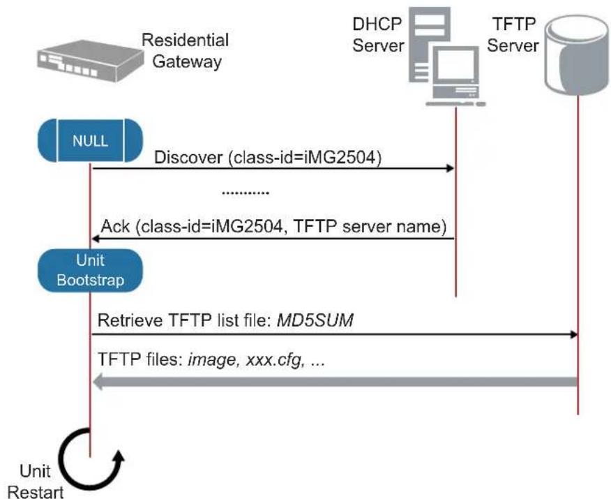
flowchart
graph TD
    A["Residential Gateway"] -->|Discover (class-id=iMG2504)| B["TFTP Server"]
    B -->|Ack (class-id=iMG2504, TFTP server name)| C["Unit Bootstrap"]
    C -->|Retrieve TFTP list file: MD5SUM| D["TFTP files: image, xxx.cfg, ..."]
    D --> E["Unit Restart"]
    F["NULL"] --> C
FIGURE 1-5 Normal Automatic Update Operation Mode
In order to inform the software update module about which files it must download from the TFTP server, a special file named MD5SUM must be created on the TFTP server.
When the software update module connects to the TFTP server, it retrieves immediately this file and then downloads each file reported in this list.
The MD5SUM file is a list of filenames where each file name has the associated MD5 value.
Note: The filename (MD5SUM) is fixed.
To create the MD5SUM file it is possible use the md5sum command available under standard Linux platforms (free md5sum applications are available also under Windows™ Operating System).
If a file reported in the MD5SUM list is already present into the gateway file-system with the same MD5 value, the software update module will skip the download of this file; otherwise it will download it.
Two files with special names are processed as follows:
- default_button.cfg - This is placed in a special partition. Refer to 1.1.11.
- bootstrap.cfg - This automatically becomes the startup-config. Refer to 1.1.11.
1.6.3 Listing Configuration Files
To list the .cfg files and their size in bytes, enter Privileged Exec Mode and enter the command:
awplus# dir
The output lists files and directories in order of modification date, descending. It looks like this:
9748 default.cfg
13320 default_button.cfg
13320 test.cfg
awplus#
1.6.4 Creating and Using Configuration Files
This section provides instructions on:
- Creating a configuration file
- Specifying the start-up configuration script
• Working with configuration files
Note: Configuration files must end with '.cfg'.
1.6.5 Creating a configuration file
A configuration file is a text file that contains a sequence of standard cli commands or an xml file. Configuration files have a .cfg extension. Your device has a default configuration script called default.cfg.
awplus# show file default.cfg
username manager privilege 15 password friend
username admin privilege 9 password admin
interface vlan1
ip address dhcp
exit
service http
service telnet
service ssh
When the device starts by using a boot cli command, a file named cli_boot_result.txt is created in order to debug errors in the configuration file. (This file is also present in tech-support)
The default_button.cfg could also be saved in a cli format.
Please note that cli files are "read only" (it is not possible to edit a cli file from a device). To modify a cli file it is necessary to import a new modified cli file.
If you try to save a boot cli file via WEB/tr69, a file named unnamed.cfg in xml format will be saved.
You can create and edit configuration files on your device by:
- saving the dynamic configuration on the device, known as the running-config (see Working with configuration files). Use the command:
awplus# copy running-config <filename.cfg>
Where
- creating a file on a remote PC, then copying it to onto your device. See Copying files for more information about using the copy commands.
Once you have created a configuration file, you can use it as the startup-config file. See Specifying the start-up configuration script for more information.
Note: You cannot edit a configuration file.
Note: Configurations are created for a particular device-type, and can only be loaded on devices of that type.
Note: Any configuration file written as a CLI sequence of commands MUST include the following: service telnet service http service ssh
1.6.6 Specifying the start-up configuration script
When you restart your device, or when it automatically restarts, it loads the config known as the boot config or startup-config file.
When you first start your device, the script set as the startup-config file is default.cfg. If desired, you can overwrite default.cfg with another configuration. Alternatively, you can change the startup-config by specifying a new file as the startup-config. Use the command:
awplus(config)# boot config-file <filename.cfg>
where filename.cfg specifies the name and location of a configuration file. At the next restart, the device loads the config in the specified file.
You can change the content of the file set as the startup-config file by:
- entering commands directly into the CLI, then saving this configuration using the command:
awplus# copy running-config startup-config
This command saves the device's dynamic configuration into the file that is currently configured as the startup-config file.
- writing commands into a configuration file (see Creating a configuration file below), then using the command:
awplus# copy SOURCE-URL startup-config
This command saves the script from the source file into the file that is currently configured as the startup-config file.
To display the name of the configuration file that is set to execute when the device restarts, enter the command:
awplus# show boot
To see the config in the startup-config file, use the command:
awplus# show startup-config
To erase the file set as the startup-config file, use the command:
awplus# erase startup-config
At the next restart that occurs, the device will first attempt to load default_button.cfg. If that is not present it will then fallback to default.cfg. See section "Start-up Sequence".
Note: When configuring the device using the Web GUI or a TR-069 tool, each configuration action results in a save. If the startup configuration is the default.cfg, then a new config is created named unnamed.cfg and that is set as the startup configuration. If the unnamed.cfg file is present and is a CLI file, Web GUI and TR-069 cannot be saved.
1.6.7 Working with configuration files
When you use the CLI or GUI to configure your device, it stores this dynamic configuration called the running-config. To view the device's running-config, use the command:
awplus# show running-config
If you turn off the device or restart it, any unsaved changes to the running-config are lost. To save the running-config as a configuration script, use the command:
awplus# copy running-config <filename>.cfg
You may have many configuration files. Storing them on a device allows you to keep a backup device with configuration scripts for every device in the network to speed up network recovery time.
1.6.8 The configuration file fallback order
The configuration fallback order is:
- configuration file
• default button configuration file
• the factory default configuration.
It is important to note the there is a distinction in system behavior between these when writing to the startup-config file and when the system boots up.
When you copy a configuration script from a source file into the startup-config file the system will write to the specified startup config. (The user must specify the startup config.)
At system startup the device goes through the fallback sequence until it finds a file that exists and is valid. For example, if the configuration file is not found then the backup configuration file becomes the current boot configuration, or startup-config, and so on. In the output displayed by the show boot command, the Current boot config parameter shows the startup-config file that the switch will load during the next boot cycle. The fallback sequence when configuration files are deleted is shown below in output from the show boot command.
In the example output below, the current boot configuration file, test.cfg, is set. This is the startup-config file that the device loads at the next boot cycle.
awplus# show boot
Boot configuration

Current software : [partition 2] AT-iMG2500-4.3_112
Current boot image : [partition 2] AT-iMG2500-4.3_112 (AtiBcm-4.3_112)
Backup boot image : [partition 1] AT-iMG2500-4.2.3 (AtiBcm-4.2.3)
Default boot config: default.cfg
Backup boot config: default_button.cfg (file exists)
Current boot config: 3play-sip.cfg (file exists)
Reset startup-config (which was test.cfg) to the backup configuration file (default_button.cfg). Note that test.cfg is not deleted – it is simply no longer marked as the startup-config.ig.
awplus# do show boot
Boot configuration
----
Current software : [partition 2] AT-iMG2500-4.3_112
Current boot image : [partition 2] AT-iMG2500-4.3_112 (AtiBcm-4.3_112)
Backup boot image : [partition 1] AT-iMG2500-4.2.3 (AtiBcm-4.2.3)
Default boot config: default.cfg
Backup boot config: default_button.cfg (file exists)
Current boot config: 3play-sip.cfg (file exists
At system startup the switch will load the default button or the default configuration file as the startup-config.
1.6.9 Copying Files To and From Your Device
This section provides instructions on:
- URL syntax
- Copying files
1.6.10 URL syntax
Many of the file management commands use the placeholder "URL" to represent the name and location of the file that you want to act on. The following table explains the syntax of this URL for each different type of file location.
Note: Only the tftp:// URL type is supported.
Table 1-8: Location of Common Files
| When you copy a file... Use this syntax: | |
| Copying with Trivial File Transfer Protocol (TFTP) | tftp://LOCATION/[DIRECTORY]/FILENAME |
1.6.11 Copying files
To copy files, use the copy commands. These commands allow you to copy files:
To copy a file, enter Privileged Exec Mode and enter the command:
awplus# copy <source-filename>
<destination-filename>
If the file already exists, the user must delete the file before trying again.
Note: There is no file system; there is a single directory where all files reside.
I.6.11.1 Copying with Trivial File Transfer Protocol (TFTP)
TFTP runs over User Datagram Protocol (UDP). It is simpler and faster than FTP but has minimal capability, such as no provisions for user authentication. Two examples on how to copy a configuration file from the TFTP server to the iMG and how to copy a show-tech report file from the iMG to a TFTP server are the following:
To copy a config file from a TFTP server to the iMG, enter Privileged Exec Mode and enter the command:
awplus# copy tftp://<server address>/[server path/] <serverfilename>.cfg <localfilename>.cfg
To copy a show-tech file from the iMG to a TFTP server, enter Privileged Exec Mode and enter the command:
awplus# copy <show-techfilename> tftp://<server address>/[server path/]<servershow-techfilename>
1.7 File Management Commands
1.7.1 File Management Commands
This chapter provides an alphabetical reference of commands used for file management.
Note: Many of the commands in this chapter use the placeholder "URL" to represent the name and location of the file that you want to act on. The following table explains the syntax of this URL for each different type of file location
Table 1-9: URL Syntax and Keyword Usage
| When you copy a file... Use this syntax: | |
| In local memory | FILENAME |
| Using Hypertext Transfer Protocol (HTTP) | http [://] [[USERNAME:PASSWORD]@] {HOSTNAME | HOST-IP} [/FILEPATH]/FILENAME |
| Using Trivial File Transfer Protocol (TFTP) | tftp://LOCATION/[DIRECTORY/]FILENAME |
Table I-10: User Access Commands
| Commands |
| boot config-file |
| boot default button |
| boot system |
| boot system recovery crc |
| boot system recovery filename |
| boot system recovery server |
| copy |
| copy running-config |
| copy startup-config |
| delete |
| dir |
| erase startup-config |
| move |
| show boot |
| show file |
| show running-config |
| show startup-config |
| show version |
BOOT CONFIG-FILE
Syntax
boot config-file
no boot config-
Description This command sets the configuration file to use during the next boot cycle.
Use the no variant of this command to set the boot configuration file to default. If the configuration file does not exist, the file is automatically created.
For an explanation of the configuration fallback order, see 1.6.8.
Feature File Management Commands
Mode Global Configuration Mode
Release 4.1
Options
| Option Description Range | Default Value | ||
| Valid configuration files must have a .cfg extension. | NA | NA | |
Note NA
Example To run the configuration file branch.cfg stored on the switch's Flash filesystem the next time the device boots up, use the commands:
awplus(config)# boot config-file branch.cfg
BOOT DEFAULT BUTTON
Syntax
awplus(config)# boot default-button
awplus(config)# no boot default-button
Description
This command enables the support for default button. If a user keeps pressed the reset button for more than 10 seconds, the iMG will restart and will execute the configuration showed in the file named default-button configuration.
The no variant of the command disables the support for the reset of the default button.
Feature File Management Commands
Mode Privileged Exec Mode
Release 4.3.2
Options NA
Note
For single image devices (i.e. iMG 1400 family), there is no backup boot image.
Example To enable the current boot configuration, use the command:
awplus(config)# boot default-button
BOOT SYSTEM
Syntax boot system partition [1|2]
boot system
Description This command sets the release file to load during the next boot cycle. The user can specify the file name as well as the partition. To know the name of the release file use the show boot command.
Feature File Management Commands
Mode Global Configuration Mode
Release 4.1
Options
| Option Description Range | Default Value | |
| partition Where all user configuration files are stored. NA NA |
Note NA
Example To run the appload in the other partition, use the commands:
awplus(config)# boot system partition 1
BOOT SYSTEM RECOVERY CRC
Syntax
boot system recovery crc
Description
This command sets the value (if set not equal to zero) that enables CRC validation of the image once it is downloaded. This only applies to the system recovery process, and not normal firmware updates. Refer to boot system recovery server. The no command restores the value to the default (0)
Description
Description see boot recovery server description
Feature File Management Commands
Mode Global Configuration Mode
Release 4.2
Options
| Option Description Range | Default Value | |
| hex value that enables CRC validation of the image once it is downloaded. | NA 0x00 |
Note
The CRC value for each image can be found in the Release Notes. This command applies only to single image devices (i.e. iMG1400).
Example To set the hex value, use the commands:
awplus(config)# boot system recovery crc 04c2cddFF
BOOT SYSTEM RECOVERY FILENAME
Syntax
boot system recovery filename
Description
This command sets the image filename that is requested from the server for recovery. The no command restores the filename to the default.
Feature File Management Commands
Mode Global Configuration Mode
Release 4.2
Options
| Option Description Range | Default Value | |
| filename The filename for the image. NA AT- | iMGI400-4.2 |
Note
This command applies only to 1400 series devices (single image).
Example To set the tftp ip address, use the commands:
awplus(config)# boot system recovery filename AT-iMG1400-4.2
BOOT SYSTEM RECOVERY SERVER
Syntax
boot system recovery server
Description
This command sets the IP address where the TFTP request is sent for emergency recovery of a single image device. The no command restores the value to the default, i.e. the IP address of the DHCP server where the iMG is connected.
Feature File Management Commands
Mode Global Configuration Mode
Release 4.2
Options
| Option Description Range | Default Value | ||
| IP_address The | IP address for the TFTP request. NA IP address | of the DHCP server | |
Note
This command applies only to 1400 series devices (single image).
Example To set the tftp ip address, use the commands:
awplus(config)# boot system recovery server 10.52.208.1
COPY
Syntax
copy <source-url> <destination-file>
copy <source-file> <destination-file>
copy <source-file> <destination-url>
Description
This command may be used to copy configuration files from a remote tftp server onto the iMG, from the iMG to a remote tftp server, or simply to make a local copy of a configuration file already present on the iMG
This command can also be used to copy tech-support .txt files from the iMG to a remote tftp server (see the show tech-support command).
Feature File Management Commands
Mode Privileged Exec Mode
Release 4.1
Options
| Option Description Range | Default Value | ||
| The name of an existing configuration file on the iMG. NA NA | |||
| The name of the new configuration file that you would like to create on the iMG | NA NA | ||
| The tftp URL of a configuration file. The file pointed by the url must be a valid configuration file with a .cfg file-name extension. | NA NA | ||
| The tftp URL of the destination configuration file. NA NA | |||
Note
It is not possible to use both
Example The following commands show an example for each syntax listed above:
awplus# copy tftp://alpha.myplace.com/newconfig.cfg newconfig.cfg
awplus# copy oldconfig.cfg backup_oldconfig.cfg
awplus# copy oldconfig.cfg tftp://alpha.myplace.com/backup_config.cfg
COPY RUNNING-CONFIG
Syntax
copy running-config
copy running-config startup-config
Description This command copies the running-config to a destination file.
Feature File Management Commands
Mode Privileged Exec Mode
Release 4.1
Options
| Option Description Range | Default Value | ||
| The tftp URL where you would like the current running-config saved. This command creates a file if no file exists with the specified filename. If a file already exists, then the CLI prompts you before overwriting the file. | NA NA | ||
| startup-config Copies the running-config into the file set as the current startup-config file. | NA NA | ||
Note NA
Example To copy the running-config into the startup-config, use the command:
awplus# copy running-config startup-config
Example To use tftp to copy the running-config as current.cfg, use the command:
awplus# copy running-config tftp://server/config_files/current.cfg
COPY STARTUP-CONFIG
Syntax
copy
Description
This command copies the startup-config script into a destination file, or alternatively copies a configuration script from a source file into the startup-config file.
Feature File Management Commands
Mode Privileged Exec Mode
Release 4.1
Options
| Option Description Range | Default Value | ||
| The tftp URL of a configuration file. This must be a valid configuration file with a .cfg filename extension. Specify this to copy the script in the file into the startup-config file. Note that this does not make the copied file the new startup file, so any further changes made in the configuration file are not added to the startup-config file unless you reuse this command. | NA NA | ||
| The destination and filename that you are saving the startup-config as. This command creates a file if no file exists with the specified filename. If a file already exists, then the CLI prompts you before overwriting the file. | NA NA | ||
Note NA
Example To copy the file Layer3.cfg to the startup-config, use the command:
awplus# copy Layer3.cfg startup-config
Example To copy the startup-config as the file oldconfig.cfg use the command:
awplus# copy startup-config oldconfig.cfg
DELETE
Syntax delete [force]
Description This command deletes configuration files and text files like the tech support file.
The use of wildcards is allowed here so commands such as these are allowed:
- awplus# delete *.cfg
- awplus# delete test*.cfg
- awplus# delete *.txt
- awplus# delete tech*.txt
Feature File Management Commands
Mode Privileged Exec Mode
Release 4.1.2
Options
| Option Description Range | Default Value | |
| force Don't prompt with individual file names before deletion.This option can also be used to force deletion of the current startup configuration." | NA NA | |
| <name> Name of the config file to delete. NA NA |
Note When the user inputs delete with a wildcard, a prompt message appears for each file to be deleted; Deletion is done for the selected files at the end of all the requests. Also, to allow the deletion of the startup config, the force option must be used.
Example To delete the file temp.cfg from the current directory, use the command:
awplus# delete temp.cfg
Example To delete the file tech-support-00700001-000229.txt from the current directory, use the command
awplus# delete tech-support-00700001-000229.txt
DIR
Syntax dir
Description This command lists the config and text files on the iMG, preceded by their size in bytes.
Feature File Management Commands
Mode Privileged Exec Mode
Release 4.1
Options NA
Note NA
Example To list the files in the current working directory, use the command:
awplus# dir
9748 default.cfg
346545 tech-support-00700001-000229.txt
13418 a1.cfg
ENABLE DEFAULT BUTTON CONFIGURATION
Syntax
awplus(config)# boot default-button
Description This command is for enabling the default button configuration.
Feature File Management Commands
Mode Privileged Exec Mode
Release 4.3.2
Options NA
Note
For single image devices (i.e. iMG 1400 family), there is no backup boot image.
Example To enable the current boot configuration, use the command:
awplus(config)# boot default-button
ERASE STARTUP-CONFIG
Syntax
erase startup-config
Description
This command deletes the file that is set as the startup-config file, which is the configuration file that the system runs when it boots up. Note that startup-config is not changed, so at the next restart, the device will attempt to load the (now deleted) file pointed to by startup-config, and will then fall-back the configuration as described in Start-up Sequence.
Feature File Management Commands
Mode Privileged Exec Mode
Release 4.1
Options NA
Note NA
Example To delete the file currently set as the startup-config, use the command:
awplus# erase startup-config
MOVE
Syntax move
Description This command may be used to move (i.e. rename) a configuration file.
Feature File Management Commands
Mode Privileged Exec Mode
Release 4.1
Options
| Option Description Range | Default Value | ||
| The name of an existing configuration file on the iMG. NA NA | |||
| The new name that you would like give to the configura-tion file. | NA NA | ||
Note NA
Example To use the move command to rename a file as a backup file:
awplus# move oldconfig.cfg backup_oldconfig.cfg
SHOW BOOT
Syntax show boot
Description This command displays the current boot configuration.
Feature File Management Commands
Mode Privileged Exec Mode
Release 4.1
Options NA
Note For single image devices (i.e. iMG 1400 family), there is no backup boot image.
Example To show the current boot configuration, use the command:
awplus# show boot
Boot configuration
Current software : AT-iMG1400-4.3.2_23
Current boot image : AT-iMG1400-4.3.2_23 (AtiBcm-4.3.2_23)
Default boot config: default.cfg
Backup boot config: default_button.cfg (file not found)
Current boot config: unnamed.cfg (file exists)
Default button : disabled
OR
awplus# show boot
Boot configuration
Current software : AT-iMG1400-4.3.2_23
Current boot image : AT-iMG1400-4.3.2_23 (AtiBcm-4.3.2_23)
Default boot config: default.cfg
Backup boot config: default_button.cfg (file not found)
Current boot config: unnamed.cfg (file exists)
Default button : enabled
SHOW FILE
Table I-11: Parameters in the output of the show boot command
| Parameter Description | |
| Current software The current software release that the device is using. | |
| Current boot image The boot image currently configured for use during the next boot cycle. | |
| Backup boot image The boot image to use during the next boot cycle if the device cannot load the main image. | |
| Default boot config The default startup configuration file. The device loads this configuration script if no file is set as the startup-config file. | |
| Backup boot config The backup boot configuration – default_button.cfg | |
| Current boot config The configuration file currently configured as the startup-config file. The device loads this configuration file during the next boot cycle if this file exists. | |
Syntax show file {
Description This command displays the contents of a configuration file or of a technical support file.
Feature File Management Commands
Mode Privileged Exec Mode
Release 4.1
Options
| Option Description | Range | Default Value | |
| Name of a configuration file or name of tech-support file | NA | NA |
Note NA
Example To display the contents of the file customer_sip.cfg, which is in the current directory, use the command:
awplus# show file customer_sip.cfg
<?xml version="1.0"?>
<DslCpeConfig version="3.0">
    <InternetGatewayDevice>
    <LANDeviceNumberOfEntries>5</LANDeviceNumberOfEntries>
    <WANDeviceNumberOfEntries>1</WANDeviceNumberOfEntries>
    <DeviceInfo>
    <FirstUseDate>0001-01-01T00:00:00Z</FirstUseDate>
    <VendorConfigFile nextInstance="33"></VendorConfigFile>
    </DeviceInfo>
    <X_BROADCOM_COM_EthernetSwitch>
    <NumberOfVirtualPorts>5</NumberOfVirtualPorts>
    <EnableVirtualPorts>TRUE</EnableVirtualPorts>
    <IfName>(null)</IfName>
    <X_ALLIEDTELESIS_COM_DscpMapping instance="1">
    <X_ALLIEDTELESIS_COM_DscpValue>45</X_ALLIEDTELESIS_COM_DscpValue>
    <X_ALLIEDTELESIS_COM_EgressQueue>3</X_ALLIEDTELESIS_COM_EgressQueue>
    </IFName>
    </InternetGatewayDevice>
    </InternetGatewayDevice>
</DslCpeConfig>
Setting up the Gateway File Management Commands
</X_ALLIEDTELESIS_COM_DscpMapping>
<X_ALLIEDTELESIS_COM_DscpMapping instance="2">
    <X_ALLIEDTELESIS_COM_DscpValue>35</X_ALLIEDTELESIS_COM_DscpValue>
    <X_ALLIEDTELESIS_COM_EgressQueue>2</X_ALLIEDTELESIS_COM_EgressQueue>
SHOW RUNNING-CONFIG
Syntax
show running-config
Description
This command displays the current configuration of the device. The output includes all non-default configuration; default settings are not displayed.
You can control the output in any one of the following ways:
(Display filtering is not supported in this release.)
- 'q' will abort the output.
- Pressing 'enter' or the space bar will advance the output by one line.
• 'r' will show all remaining output.
Feature File Management Commands
Mode All command modes
Release 4.1
Options NA
Note NA
Example To display the current dynamic configuration of your device, use the command:
awplus# show running-config
?xml version="1.0"?
<DslCpeConfig version="3.0">
    <InternetGatewayDevice>
    <LANDeviceNumberOfEntries>1</LANDeviceNumberOfEntries>
    <WANDeviceNumberOfEntries>1</WANDeviceNumberOfEntries>
    <DeviceInfo>
    <FirstUseDate>0001-01-01T00:00:00Z</FirstUseDate>
    <VendorConfigFile nextInstance="4" ></VendorConfigFile>
    </DeviceInfo>
    <Layer2Bridging>
    <BridgeNumberOfEntries>1</BridgeNumberOfEntries>
    <FilterNumberOfEntries>6</FilterNumberOfEntries>
    <MarkingNumberOfEntries>0</MarkingNumberOfEntries>
    <AvailableInterfaceNumberOfEntries>6</AvailableInterfaceNumberOfEntries>
    <Bridge instance="1">
    <BridgeKey>1</BridgeKey>
    <BridgeEnable>TRUE</BridgeEnable>
    <BridgeName>Default</BridgeName>
    <VLANID>1</VLANID>
    </Bridge>
    <Bridge nextInstance="2" ></Bridge>
    <Filter instance="1">
    <FilterKey>1</FilterKey>
--More-- (6% of 13326 bytes)
SHOW STARTUP-CONFIG
Syntax show startup-config
Description This command displays the contents of the start-up configuration file, which is the file that the device runs on start-up.
Feature File Management Commands
Mode Privileged Exec Mode
Release 4.1
Options NA
Note NA
Example To display the contents of the current start-up configuration file, use the command:
awplus# show startup-config
<?xml version="1.0"?>
<DslCpeConfig version="3.0">
<InternetGatewayDevice>
<LANDeviceNumberOfEntries>1</LANDeviceNumberOfEntries>
<WANDeviceNumberOfEntries>1</WANDeviceNumberOfEntries>
<DeviceInfo>
<FirstUseDate>0001-01-01T00:00:00Z</FirstUseDate>
<VendorConfigFile nextInstance="4" ></VendorConfigFile>
</DeviceInfo>
<Layer2Bridging>
<BridgeNumberOfEntries>1</BridgeNumberOfEntries>
<FilterNumberOfEntries>6</FilterNumberOfEntries>
<MarkingNumberOfEntries>0</MarkingNumberOfEntries>
<AvailableInterfaceNumberOfEntries>6</AvailableInterfaceNumberOfEntries>
<Bridge instance="1">
<BridgeKey>1</BridgeKey>
<BridgeEnable>TRUE</BridgeEnable>
<BridgeName>Default</BridgeName>
<VLANID>1</VLANID>
</Bridge>
<Bridge nextInstance="2" ></Bridge>
<Filter instance="1">
<FilterKey>1</FilterKey>
--More-- (6% of 13326 bytes)
SHOW VERSION
Syntax
show version [abbreviated]
Description
This command displays the version number and copyright details of the current application build (name, date and type) with the indication of AlliedWare Plus CLI, VoIP and Uboot version, your device is running, and an extended list of all copyrights of application tools used.
For information on output options, see Controlling Command Output.
Feature File Management Commands
Mode User Exec and Privileged Exec Mode
Release 4.2
Options NA
Note
CLI and UBoot version information is added in 4.2
Example To display the version details of your currently installed software, use the command:
awplus # show version
AT-iMG1400 4.3 GM 11/04/13 14:05
Application Build name : AT-iMG1400-4.3
Application Build date : 14:05 11/04/13
Application Build type : GM
802.11 radio version : 0.9.17.1/v1.0
CFE build date : Wed Sep 26 10:42:31 EDT 2012
Copyright (c) 2001-2013 Allied Telesis Holdings K. K. - all rights reserved.
Copyright (c) 2001-2011 Broadcom Corporation.
The following portions of this product are covered by the GNU GPLv2, Source code may be downloaded from:
http://www.alliedtelesis.co.nz/support/gpl/awp.html
The license text can be found at:
http://www.gnu.org/licenses/gpl-2.0.html
Example To display the abbreviated listing, use the command:
awplus# show version abbreviated
Setting up the Gateway System Configuration and Monitoring Commands
AT-iMG1400 4.3 GM 11/04/13 14:05
Application Build name : AT-iMG1400-4.3
Application Build date : 14:05 11/04/13
Application Build type : GM
802.11 radio version : 0.9.17.1/v1.0
VoIP version : AtiVoip-2.3_37
CLI version : AtiAwpCli-1.3_93
Uboot version : AtiUboot-1.0_23
Uboot build date : Sep 26 2012 10:42:19
Uboot script version : 1.0.8
CFE version : 1.0.38 for BCM96828 (32bit, SP, BE)
CFE build date : Wed Sep 26 10:42:31 EDT 2012
awplus#
1.8 System Configuration and Monitoring Commands
1.8.1 System Configuration and Monitoring Commands
This chapter provides an alphabetical reference of commands for configuring and monitoring the system.
Table I-12: System Configuration and Monitoring Commands
| Commands |
| clock set |
| clock summer-time |
| clock timezone |
| hostname |
| psu-management |
| show clock |
| show cpu |
| show memory shared |
| show system |
| show system pluggable |
| show system psu |
| show tech-support |
| terminal monitor |
CLOCK SET
Syntax
clock set
Description
This command sets the time and date for the system clock.
Configure the timezone before setting the local time. Otherwise, when you change the timezone, the device applies the new offset to the local time. Note that in 4.1 seconds is always set at 00.
Feature System Configuration and Monitoring Commands
Mode Global Configuration Mode
Release 4.1
Options
| Option Description Range | Default Value | ||
| Local | time in 24-hour format NA NA | ||
| Day of the current month <1-31> | NA | NA | |
| The first three letters of the current month.The first letter must be capitalized. | NA NA | ||
| Current year <2000-2035> | NA | NA | |
Note
If Network Time Protocol (NTP) is enabled, then you cannot change the time or date using this command. NTP maintains the clock automatically using an external time source. If you wish to manually alter the time or date, you must first disable NTP.
Example To set the time and date on your system to 2pm on the 3rd of November 2011, use the command:
awplus(config)# clock set 14:00 03 Nov 2011
CLOCK SUMMER-TIME
Syntax
clock summer-time
no clock summer-time
Description
This command enables the management of the daylight saving time. Once this command has been typed, the summertime will start and stop automatically, depending on the time zone set via clock timezone (see next pages). The no variant of this command disables the summertime management and returns to the default.
By default, the device has summertime management disabled.
Feature System Configuration and Monitoring Commands
Mode Global Configuration Mode
Release 4.1
Options NA
Note NA
Example To start summertime management, use the command:
awplus(config)# clock summer-time
Example To stop summertime management, use the command:
awplus(config)# no clock summer-time
CLOCK TIMEZONE
Syntax
clock timezone
no clock timezone
Description
This command defines the device's clock timezone. The timezone is set as an offset to the UTC.
The no variant of this command resets the time zone to UTC (+00:00).
By default, the system time is set to UTC.
Configure the timezone before setting the local time. Otherwise, when you change the timezone, the device applies the new offset to the local time.
If summertime management is enabled, the summertime will follow the rules applied in the time zone set, without the need to specify them.
In the table below, the available time zones are listed. Note that 'Abbreviation' corresponds to the parameter
Table I-13: Time Zones Available
| Abbreviation Name | UTC Offset | |
| AFT Afghanistan Time | +04:30 | |
| AKST Alaska Standard Time | -09:00 | |
| AMT Armenia Time | +04:00 | |
| ART Argentina Time | -03:00 | |
| AST Atlantic Standard Time | -04:00 | |
| AST-Arabia | AST-Arabia | +03:00 |
| AZOT | Azores Time | -01:00 |
| BOT | Bolivia Time | -04:00 |
| BRT | Brasilia Time | -03:00 |
| BST | Bangladesh Standard Time | +06:00 |
| CAT | Central Africa Time | +02:00 |
| CDT Central Daylight Time | -06:00 | |
| CEST | Central European Summer Time | +02:00 |
| CET Central European Time | +01:00 | |
| CLT Chile Standard Time | -04:00 | |
| COT Colombia Time | -05:00 | |
| CST-Australia | Australia Central Standard Time | +09:30 |
| CST-China | China Standard Time | +08:00 |
| CST-USA | USA Central Standard Time | -06:00 |
Table I-13: Time Zones Available
| Abbreviation | Name | UTC Offset |
| CVT Cape Verde Time -01:00 | ||
| EEST Eastern European Summer Time +03:00 | ||
| EET Eastern European Time +02:00 | ||
| EST-Australia Australia Eastern Standard Time +10:00 | ||
| EST-USA USA Eastern Standard Time -05:00 | ||
| FJT Fiji Time +12:00 | ||
| GMT | Greenwich Mean Time | +00:00 |
| GST | Gulf Standard Time | +04:00 |
| HAST | Hawaii-Aleutian Standard Time | -10:00 |
| IRST Iran Standard Time | +03:30 | |
| IST-India | India Standard Time | +05:30 |
| IST-Israel | Israel Standard Time | +02:00 |
| JST Japan Standard Time | +09:00 | |
| KRAT | Krasnoyarsk Time +07:00 | |
| KST | Korea Standard Time | +09:00 |
| MAGT | Magadan Time | +11:00 |
| MDT | Mountain Daylight Time | -07:00 |
| MMT | Myanmar Time | +06:30 |
| MSK Moscow Standard Time | +03:00 | |
| MST | Mountain Standard Time | -07:00 |
| MTZ | Mountain Time Zone | -07:00 |
| NOVT | Novosibirsk Time | +06:00 |
| NPT Nepal Time | +05:45 | |
| NST | Newfoundland Standard Time | -03:30 |
| NZST | New Zealand Standard Time | +12:00 |
| O | Oscar Time Zone | -02:00 |
| PGT | Papua New Guinea Time | +10:00 |
| PST | Pacific Standard Time | -08:00 |
| SBT Solomon Islands Time | +11:00 | |
| SGT | Singapore Time | +08:00 |
| ULAT | Ulaanbaatar Time | +08:00 |
Table I-13: Time Zones Available
| Abbreviation | Name | UTC Offset |
| UTC Universal Time Clock +00:00 | ||
| UZT Uzbekistan Time +05:00 | ||
| VLAT Vladivostok Time +10:00 | ||
| WAT West Africa Time +01:00 | ||
| WET Western European Time +00:00 | ||
| WGT | West Greenland Time | -03:00 |
| WIB | Western Indonesian Time | +07:00 |
| WST-Australia | Australia Western Standard Time | +08:00 |
| WST-Samoa | West Samoa Time | -11:00 |
| Y | International Date Line West | -12:00 |
| YAKT Yakutsk Time +09:00 | ||
| YEKT | Yekaterinburg Time | +05:00 |
Feature System Configuration and Monitoring Commands
Mode Global Configuration Mode
Release 4.2
Options
| Option | Description | Default Value | Default Value |
| The abbreviation of the timezone, up to 6 characters long. | NA | NA |
Note NA
Example To set the timezone to New Zealand Standard Time, use the command:
awplus(config)# clock timezone NZST
Example To set the time zone to Eastern Standard Time in the USA, use the command:
awplus(config)# clock timezone EST-USA
HOSTNAME
Syntax
hostname
Description
This command sets the name applied to the device as shown at the prompt. The hostname is:
• displayed in the output of the show system command
- displayed in the CLI prompt so you know which device you are configuring
- stored in the MIB object sysName
Use the no variant of this command to reset the hostname to the default value (awplus).
The prompt has a fixed maximum length. If the hostname is too long to be fully displayed within the prompt it will be truncated and have "." appended to indicate this. The CLI submode will always be displayed in full - so the degree of truncation of the hostname will vary between submodes. Refer to the example below.
To specify or modify the host name, use the hostname global configuration command. The host name is used in prompts and default configuration filenames.
The name must also follow the rules for ARPANET host names. The name must start with a letter, end with a letter or digit, and use only letters, digits, and hyphens, and contain no spaces. Refer to RFC 1035.
Feature System Configuration and Monitoring Commands
Mode Global Configuration Mode
Release 4.1
Options
| Option Description Range | Default Value | ||
| Specifies the network name of the system. | NA | awplus. | |
Note NA
Example To set the system name to HQ-Sales, use the command:
awplus(config)# hostname HQ-Sales HQ-Sales(config)#
PSU-MANAGEMENT
Syntax
psu-management
no psu-management
Description
The first one enables the PSU Management System, the second one disables it.
Feature System Configuration and Monitoring Commands
Mode User Exec and Privileged Exec Mode
Release 4.3.1
Options NA
Note
When enabling the PSU management runtime, battery traps are sent so to inform about the battery status, exactly like at startup.
Example To display the PSU Management System use the command:
awplus(config)# do show system psu
System PSU Status
PSU Management System : running
Alarm Status:
PSU Battery Missing : alarm present!
PSU Replace Battery : alarm present!
PSU Battery Low : alarm present!
PSU on Battery : alarm present!
awplus(config)# no psu-management
awplus(config)# do show system psu
System PSU Status
PSU Management System : not running
Alarm Status:
PSU Battery Missing : alarm present!
PSU Replace Battery : alarm present!
PSU Battery Low : alarm present!
PSU on Battery : alarm present!
awplus(config)# psu-management
awplus(config)# do show system psu
System PSU Status
PSU Management System : running
Alarm Status:
PSU Battery Missing : alarm present!
PSU Replace Battery : alarm present!
PSU Battery Low : alarm present!
PSU on Battery : alarm present!
awplus (config) #
Setting up the Gateway System Configuration and Monitoring Commands
SHOW CLOCK
Syntax show clock
Description This command displays the system's current configured local time and date. It also displays other clock related information such as timezone and summertime configuration.
Feature System Configuration and Monitoring Commands
Mode User Exec and Privileged Exec Mode
Release 4.1
Options NA
Note NA
Example To display the system's current local time, use the command:
awplus# show clock
Local Time: Mon, 29 Aug 2011 13:56:06 +1200
UTC Time: Mon, 29 Aug 2011 01:56:06 +0000
Timezone: NZST
Timezone name: Auckland, Wellington
Timezone offset: +12:00
Summer time : disabled
Table I-14: Parameters in the output of the show clock command
| Parameter Description | |
| Local Time Current local time. | |
| UTC Time Current UTC time. | |
| Timezone The current configured | timezone acronym. |
| Timezone Name The current configured | timezone name. |
| Timezone Offset Number of hours offset to UTC. | |
| Summer time | Specify if daylight saving time is running or not |
SHOW CPU
Syntax show cpu
Description This command displays a list of running processes with their CPU utilization.
Feature System Configuration and Monitoring Commands
Mode User Exec and Privileged Exec Mode
Release 4.1
Options NA
Note NA
Example To show the cpu utilization of current processes, sorting them by the number of threads the processes are using, use the command:
awplus# show cpu
System load averages:
1 minute: 0.00, 5 minutes: 0.00, 15 minutes: 0.00
user processes
| pid name | thrds | cpu% | pri | state | sleep% | runtime |
| 216 (sh) | 1 | 0.00 | 15 | sleep | N/A | 490 |
| 324 (swmdk) | 3 | 3.13 | 15 | sleep | N/A | 1425839 |
| 338 (smd) | 1 | 0.00 | 15 | sleep | N/A | 98108 |
| 354 (syslogd) | 1 | 0.00 | 15 | sleep | N/A | 20 |
| 355 (klogd) | 1 | 0.00 | 15 | sleep | N/A | 4 |
| 356 (dnsproxy) | 1 | 0.00 | 15 | sleep | N/A | 2 |
| 646 (dhcpc) | 1 | 0.00 | 15 | sleep | N/A | 9 |
| 670 (cli_bep) | 1 | 0.00 | 15 | sleep | N/A | 1103 |
| 671 (usbconsole) | 1 | 0.00 | 15 | sleep | N/A | 59 |
| 9924 (telnetd) | 1 | 0.00 | 15 | sleep | N/A | 10 |
| 9925 (awp_cli) | 1 | 3.13 | 15 | run | N/A | 36 |
Kernel Threads
| pid name | cpu% | pri | state | sleep% | runtime |
| 1 (init) | 0.00 | 15 | sleep | N/A | 89 |
| 2 (kthreadd) | 0.00 | 10 | sleep | N/A | 0 |
| 3 (sirq-high/0) | 0.00 | 15 | sleep | N/A | 0 |
| 4 (sirq-timer/0) | 0.00 | 15 | sleep | N/A | 69 |
| 5 (sirq-net-tx/0) | 0.00 | 15 | sleep | N/A | 461 |
| 6 (sirq-net-rx/0) | 0.00 | 15 | sleep | N/A | 1325 |
| 7 (sirq-block/0) | 0.00 | 15 | sleep | N/A | 0 |
| 8 (sirq-tasklet/0) | 0.00 | 15 | sleep | N/A | 2821 |
| 9 (sirq-sched/0) | 0.00 | 15 | sleep | N/A | 0 |
| 10 (sirq-hrtimer/0) | 0.00 | 15 | sleep | N/A | 0 |
| 11 (sirq-rcu/0) | 0.00 | 15 | sleep | N/A | 51 |
| 12 (events/0) | 0.00 | 10 | sleep | N/A | 2 |
| 13 (khelper) | 0.00 | 10 | sleep | N/A | 669 |
| 16 (async/mgr) | 0.00 | 10 | sleep | N/A | 0 |
| 68 (kblockd/0) | 0.00 | 10 | sleep | N/A | 0 |
| 77 (khubd) | 0.00 | 10 | sleep | N/A | 0 |
| 108 (pdflush) | 0.00 | 15 | sleep | N/A | 0 |
| 110 (kswapd0) | 0.00 | 25 | sleep | N/A | 0 |
| 112 (crypto/0) | 0.00 | 10 | sleep | N/A | 0 |
| 172 (mtdblockd) | 0.00 | 10 | sleep | N/A | 264 |
Setting up the Gateway System Configuration and Monitoring Commands
| 293 (bcmsw) | 0.00 | 15 | sleep | N/A | 0 |
| 294 (bcmsw_timer) | 0.00 | 15 | sleep | N/A | 0 |
| 339 (ssk) | 0.00 | 15 | sleep | N/A | 2084 |
| 653 (snmpd) | 0.00 | 15 | sleep | N/A | 22 |
| 667 (cmfd) | 0.00 | 15 | sleep | N/A | 12 |
| 674 (ati_voice) | 0.00 | 15 | sleep | N/A | 30 |
| 707 (udhcpd) | 0.00 | 15 | sleep | N/A | 0 |
SHOW MEMORY SHARED
Syntax show memory shared
Description This command displays basic shared memory and heap memory usage statistics present in tech-support
Feature System Configuration and Monitoring Commands
Mode User Exec and Privileged Exec Mode
Release 4.2
Options NA
Note NA
Example To display shared memory allocation used on the switch, use the command:
| awplus# show memory shared | |
| Total MDM Shared Memory Region : 416KB | |
| Shared Memory Usable : 000338KB | |
| Shared Memory in-use : 000077KB | |
| Shared Memory free : 000260KB | |
| Shared Memory allocs : 077545 | |
| Shared Memory frees : 076109 | |
| Shared Memory alloc/free delta : 001436 |
Heap bytes in-use : 000016
Heap allocs : 000037
Heap frees : 000036
Table I-15: Parameters in the output of the show cpu command
| Parameter Description | |
| System load averages The average number of processes waiting for CPU time for the periods stated. | |
| Current CPU load Current | CPU utilization specified by load types. |
| CPU averages Average CPU | utilization for the periods stated. |
| pid Identifier number of the process. | |
| name A shortened name for the process | |
| thrds | Number of threads in the process. |
| cpu% | Percentage of CPU utilization that this process is consuming. |
| pri | Process priority state. |
| state | Process state; one of"run","sleep","zombie", and"dead". |
| sleep% | Percentage of time that the process is in the sleep state. |
Setting up the Gateway System Configuration and Monitoring Commands
Table I-15: Parameters in the output of the show cpu command (Continued)
| Parameter Description | |
| runtime The time that the process has been running for, measured in jiffies. A jiffy is the duration of one tick of the system timer interrupt. | |
SHOW SYSTEM
Syntax
show system
Description
This command displays general system information about the device, including the hardware installed, memory, and software versions loaded. It also displays location and contact details when these have been set.
Feature System Configuration and Monitoring Commands
Mode User Exec and Privileged Exec Mode
Release 4.1.2
Options NA
Note NA
Source
Example To display the system information, use the command:
| awplus# show system | |||||
| Switch System Status | Sun Jan 25 01:43:32 1970 | ||||
| Board | ID | Bay | Board Name | Rev | Serial Number |
| Base | iMG2504 | X1 | ATNLAB0000001 | ||
Memory: DRAM: 123680 kB Used: 57652 kB Available: 66028 kB
| Environmental Status : Normal | |
| Uptime | : 24 days 01:43:32 |
| Bootloader version | : AtiUboot-1.0_07 |
| VoIP version | : AtiVoip-2.0_110 |
| Current Software | : AT-iMG2500-4.1 |
| Software version | : AtiBcm-4.1 GM |
| Build date | : 22:33 03/08/11 |
| Current boot config | : unnamed.cfg (file exists) |
| Territory | : |
| System Name | : |
| System Contact | : |
| System Location | : |
| awplus# | |
show system pluggable [diagnostics]
Description
This command displays information about the pluggable transceivers, such as SFPs, which are currently installed in your switch.
Feature System Configuration and Monitoring Commands
Mode User Exec and Privileged Exec Mode
Release 4.2
Options
| Option Description Range | Default Value | |
| diagnostics Shows digital diagnostic information retrieved from the SFP EEPROM. Only SFP modules that implement "internal" calibration show this output. | NA NA |
Note NA
Source
Example To display the system information on the power, use the command:
awplus# show system pluggable
Port1.0.6
[EMPTY]
Vendor Name: ATI
Device Name: AT-SPBD10-13
Device Type: BASE-BX10
Serial Number: A03243R124300045
Manufacturing Datecode: 12102501 <<<<<<<<
SFP Laser Wavelength: 1310nm
Link Length Supported
Single Mode Fiber : 10Km
OM1 (62.5um) Fiber: -
OM2 (50um) Fiber : -
Diagnostic Calibration: -
SHOW SYSTEM PSU
Syntax show system psu
Description This command displays general system information about the power system and if any alarms are present.
Feature System Configuration and Monitoring Commands
Mode User Exec and Privileged Exec Mode
Release 4.1.2
Options NA
Note NA
Source
Example To display the system information for power, use the command:
awplus# show system psu PSU Management System : running
Alarm Status: PSU Battery Missing : alarm present! PSU Replace Battery : alarm present! PSU Battery Low : alarm present! PSU on Battery : alarm present! awplus#
SHOW TECH-SUPPORT
Syntax
show tech-support [all]
Description
This command generates system and debugging information for the switch and saves it to a file.
The command generates a large amount of output and the output is saved into a file. The output file name is written once the command has been completed. The name is 'tech-support-' followed by date and time; the extension is .txt (an example could be: tech-support-00700001-000037.txt).
If all is specified the command captures the full list of information of the device.
The show tech-support command is useful for collecting a large amount of information about your switch for troubleshooting purposes. The output of this command can be provided to technical support representatives when reporting a problem.
The output of the command ‘show tech-support’ includes all these sections. Each one is the output of the command having the same name, unless specified differently below (in this case the Example shows the output):
• show clock (just the current date and time)
• show system
• show version abbreviated
• show boot
• show security-password
- dir
• show system psu
• show system pluggable
• show system pluggable diagnostics
• show hpna stations
• show w t e s t
• s h o w v l a n
• e t c .
The output of the command ‘show tech-support all’ includes the same sections plus few additional ones.
Options
| Option Description Range | Default Value | |
| all Output full troubleshooting information for all protocols and the device | NA NA |
Feature System Configuration and Monitoring Commands
Mode Privileged Exec Mode
Release 4.2
Note In 4.2, the output has been expanded to include additional show commands, including those for IPv6.
Setting up the Gateway System Configuration and Monitoring Commands
Example To capture the basic set of show output for the technical support, use the command:
awplus# show tech-support

Generating output ...

Generated output to tech-support-20130520-095529.txt <<<

awplus# show file tech-support-20130520-095529.txt

....SHOW_TECH_SUPPORT

....System-Level-Information

----clock----
....
TERMINAL MONITOR
| Syntax | terminal monitorterminal no monitor |
| Description | This command displays debugging output on a terminal. Note that logs continue to be sent to the syslog system; this allows the user to view the logs as they are produced.To display the cursor after a line of debugging output, press the Enter key.Use the command terminal no monitor to stop displaying debugging output on the terminal, or use the timeout option to stop displaying debugging output on the terminal after a set time.By default displaying debug out is disabled. |
Feature System Configuration and Monitoring Commands
Mode Privileged Exec Mode
Release 4.1
Options NA
Note NA
Example To display debugging output on a terminal, enter the command:
awplus# terminal no monitor
awplus# Aug 7 15:09:59 (none) user.info awp_cli: User manager executed "end". Returned CParser_OK.

Aug 7 15:10:08 (none) user.notice syslog: Got a new message 66
Aug 7 15:10:08 (none) user.notice syslog: IGMP Pkt Rcvd from src 0xc0a8640c and dst 0xe-002023f with
Aug 7 15:10:08 (none) user.notice syslog: mcpd_group_rep_update_switch_ati:282: echo
"L:mmac add 0 2
Aug 7 15:10:13 (none) user.notice syslog: Got a new message 66
Aug 7 15:10:13 (none) user.notice syslog: IGMP Pkt Rcvd from src 0xc0a8640c and dst 0xe-10a0a0a with
Aug 7 15:10:13 (none) user.notice syslog: mcpd_group_rep_update_switch_ati:282: echo
"L:mmac add 0 2
Aug 7 15:10:24 (none) user.notice syslog: Got a new message 66
Aug 7 15:10:24 (none) user.notice syslog: IGMP Pkt Rcvd from src 0xac2005fe and dst 0xe0000001 with
Aug 7 15:10:24 (none) user.notice syslog: MCPD_IGMP_MEMBERSHIP_QUERY 75
Aug 7 15:10:25 (none) user.notice syslog: Got a new message 66
Aug 7 15:10:25 (none) user.notice syslog: IGMP Pkt Rcvd from src 0xc0a8640c and dst 0xe-10a0a0a with
Aug 7 15:10:26 (none) user.notice syslog: mcpd_group_rep_update_switch_ati:282: echo
"L:mmac add 0 2
Example To stop displaying debugging output on the terminal, use the command:
awplus# terminal no monitor
1.9 Software Update
1.9.1 Introduction
The iMG supports several different means of software update:
- The CLI copy command may be used to download a specific software image from a remote tftp server using a tftp://
URI. See section How to Upgrade the Firmware. - The TR-69 Download method may be invoked by an ACS to force the iMG to download a specific software image. Refer to your ACS documentation.
- The iMG can be configured to check a remote tftp server for updated software and/or configuration files whenever a DHCP lease is obtained or renewed.
- The CLI swupdate command can be used to check a remote ftp server for updated software and/or configuration files.
This section describes the swupdate command. This command allows the user to configure & initiate the downloading of updated software and/or configurations from a remote ftp server by means of a list file containing file names & corresponding MD5 checksums.
When the swupdate now command is invoked, the iMG attempts to download a file named MD5SUM from the ftp server. The contents of this file is then used to determine which (if any) software and/or configuration files available on the ftp server are not already present on the iMG, and then those files not already present are downloaded.
1.9.2 Software Update Command List
Table I-16: Software Update Commands
| Commands |
| show swupdate |
| swupdate |
| swupdate now |
SHOW SWUPDATE
Syntax show swupdate
Description This command shows the configuration of the iMG swupdate client
Feature Update Commands
Mode Privileged Exec Mode
Release 4.1
Options NA
Note NA
Example See the example output below:
awplus# show swupdate
Software Update Configuration
| FTP server name/address | : beethoven.atg.lc |
| FTP Server path | : decomposing/composer |
| FTP server username | : manager |
| FTP server password | : friend |
SWUPDATE
Syntax swupdate {password
no swupdate {password | username | server | server-path}
Description This command configures the iMG software update client.
Use the no variant of this command to remove configured options.
Feature Update Commands
Mode Global Configuration Mode
Release 4.1
Options
| Option Description | Default Value | Default Value | |
| A string of up to 64 characters. May not include white-space. | NA manager | ||
| A string of up to 64 characters. May not include white-space. | NA friend | ||
| A valid dotted-numeric IPv4 address NA NA | |||
| A valid IP domain name | NA NA | ||
| A string of up to 64 characters. May not include white-space and must contain valid path-name syntax for the remote ftp server. | NA NA | ||
Note NA
Example To configure the iMG software update client, use the commands:
awplus(config)# swupdate server aladdins-cave.com awplus(config)# swupdate server-path jewellery_bor awplus(config)# swupdate password open_sesame awplus(config)# swupdate username treasure_trove
SWUPDATE NOW
Syntax swupdate now [noreboot]
Description This command invokes the swupdate client which will attempt to download software and configurations not already present on the iMG.
Feature Update Commands
Mode Privileged Exec & Global Configuration
Release 4.1
Options
| Option Description Range | Default Value | |
| noreboot Prevents the iMG from automatically rebooting if one or more files have been downloaded. | NA NA |
Note - If the swupdate now command downloads a configuration file named 'bootstrap.cfg', this file will be set as the startup-config (i.e. it will be the configuration loaded when the iMG is restarted).
- If the swupdate now command downloads one or more files - on completion of the download the iMG will by default reboot. You can use the swupdate now noreboot variant to prevent this automatic reboot. If no new software or configurations are downloaded no reboot will occur.
- The swupdate client will down load a maximum of one software image per-invocation (this constraint does not apply to configuration files). If you wish to upgrade both image partitions you should invoke the swupdate now command twice (allowing the iMG to reboot between invocations).
- If a voice call is in progress and this command is entered, the device performs the upgrade but not the restart until the call is taken down.
Example To download the software and prevent the automatic reboot, use the following commands:
awplus(config)# swupdate now noreboot
Downloading MD5SUM
Downloading AT-iMG2500-4.1.1_04
Downloading test_config.cfg
Starting image flash write of AT-iMG2500-4.1.1_04. This may take several minutes - please be patient
Starting flash write of user configuration files
awplus(config)#
1.10 Debugging and Logging
1.10.1 Introduction
The AT iMG software has a comprehensive debugging and logging facility in various subsystems and components. This chapter describes how to start/stop debugging and logging.
Warning: At the Privileged Exec Mode, the User can enter a proprietary debug level via the "debug" command – and gain access to a lower level command set. Only use this command when instructed to do so by Allied Telesis personnel.
1.10.2 Debugging
Many subsystems have debug commands. Debug commands, used with parameters, log subsystem-specific information at a specific severity level.
The system is always writing logs at the error severity level for all subsystems, and is the default log stream. On using a debug command, another stream is added to this default log stream, and this stream continues to generate output until the no parameter is used with the command.
Note: Log generation is always on, and by default all logs are error.
Note: It is possible to change some logs to notice or debug; no debug all restores all to the default level of error.
Note: With voice logs, specific subsystems are enabled individually, while the overall log level is controlled as above. Prior to setting the voip log level to debug or notice, it is recommended to disable all voip subsystems, and then enable the specific underlying one that you want --- i.e.
no debug voip
debug voip category aep
Note: To specify where logging output is sent, use the log commands, explained below.
To turn on debugging for a subsystem at a specified severity level, use the command debug. For example;
awplus(config)# debug igmp level notice
The subsystems that are available are:
- access Intrusion attempt of a not permitted host
- all All applications
• hpna Home Phoneline Networking Alliance (HPNA) - httpd Hypertext Transfer Protocol (HTTP)
• igmp Internet Group Management Protocol (IGMP) - looproot Loop-protection
- pppoe Point-to-Point Protocol over Ethernet (PPPoE)
- snmpd Simple Network Management Protocol (SNMP)
- sshd Secure Sheel Server
- swupdate Software Update Application
• telnetd Terminal Emulation Server
• voip Voice over IP (VOIP)
• tr69 Broadband Forum TR-69 Remote Management Protocol (TR-69)
- upnp Enable logging for Universal Plug and Play (UPnP)
Also included is access, for attempted intrusions. This is not specifically a subsystem but deals with security.
The severity levels in order are as follows. (The error set is the smallest, with notice including error and debug including notice.)
- error
- notifications (notice)
- debugging (debug)
To turn off debugging, use the no debug command. When a subsystem is specified with the no debug command, debugging is stopped for the specified subsystem. To stop all debugging except for the default stream, use the all parameter.
awplus(config)# no debug all
1.10.3 Logging
The log messages as they are processed can be sent to a log server or to the terminal. (In a future release, the log messages can be sent to a host based on the subsystem and severity level.)
The following types of logging output are available:
- terminal
- host
Note: Terminal log and console log cannot be set at the same time. If console logging is enabled then the terminal logging is turned off.
The buffered log is a file stored in persistent memory on the device. Because it is stored in RAM its content will survive (or persist) a restart, but will not survive a power cycle of the device. A device can only have one instance of the buffered log. The buffered log is enabled by default and has a filter to include messages with a severity level of 'notifications' and above.
1.10.3.1 Example - Creating a Log Stream that includes igmp and is displayed at the terminal monitor
- Turn on the debug options by using the relevant debug command at the config level.
awplus(config)# debug igmp level debug
- Run the terminal monitor command to send output to the terminal
awplus# terminal monitor
This is a sample output of the debug igmp events command displayed on the terminal:
awplus#terminal monitor
Dec 2 16:41:49 localhost IGMP[6518]: IGMP: IGMP message sent to 10.10.23.60/32 via interface vlan2
Dec 2 16:41:57 localhost IGMP[6518]: IGMP: Received an IGMP message of type IGMP Reservation from 192.168.0.60 via interface vlan2
Dec 2 16:41:57 localhost IGMP[6518]: IGMP: Received a IGMP message from 10.10.23.60/32
I.10.3.2 Logging of Executed Commands (Info level)
To track command input, each executed command is logged as an Info level log (although they are not true Info level logs), and includes the user-id of the user who executed the command. Also included is the command's status value (whether the command succeeded).
Note: These executed commands are always created, and are not affected by the log level.
An example of this log is as follows;
Jan 1 00:00:45 (none) user.info awp_cli: User manager executed "enable". Returned CParser_OK. 100
Jan 1 00:00:52 (none) user.info awp_cli: User manager executed "terminal monitor". Returned CParser_OK. 111
For reboots, the log shows that the reboot was caused by a command, but not the user-id.
Note: For reboots the log can show the source of the reboot, which may not be with a command. Sources can be:
- CLI command
- WEB command
- TR69 command
- SWUPDATE command
- Voice command
1.10.3.3 Duplicate Logs Suppressed
When a duplicate log is produced, it a suppressed and counted until a different message is received. When there is a new message, "Previous message duplicated x times" is printed. Following is an example:
Dec 1 11:04:33 (none) user.info awp_cli: User manager executed "hostname pippol". Returned CParser_OK. 109
Dec 1 11:04:39 (none) user.info Previous message duplicated 3 times 74
Note: Timestamps are ignored in the string comparison. Also, the last digit is the length of the log message and is not part of the log.
I.10.3.4 Logging of voip Subsystem
For the voip subsystem, there are several categories (mgcp, aep, etc.). By default, all the voip logs are enabled at the error level. To control the voip logging, the user should disable all voip logs and enable them selectively at the appropriate level. Refer to Voice Service Logging.
1.10.3.5 Host log
A host log sends log messages to a remote syslog server. A device may have many syslog hosts configured. To configure or remove a host use the commands:
log host <ip_address>
no log host
where
It is not possible to view the log messages sent to this type of output as they are not retained on the device. They must be viewed on the remote device. The other host log commands are:
show log config
which shows what is on the syslog server.
I.11 Debugging and Logging Commands
I.II.1 Debugging and Logging Commands
This chapter provides an alphabetical reference of commands for debugging and logging.
Table I-17: Logging Commands
| Commands |
| clear log |
| debug |
| log host |
| show log |
| show log config |
Setting up the Gateway Debugging and Logging Commands
CLEAR LOG
Syntax clear log
Description This command removes the contents of the logs that are persistent memory.
Feature Logging Commands
Mode Privileged Exec Mode
Release 4.1.2
Options NA
Note This command clears all logs: in the iMG there is no concept of buffered versus permanent logs (and therefore no separate commands to delete the two types).
Example To delete the contents of the logs, input:
awplus# clear log
DEBUG
Syntax debug
Description This command defines a stream of error logs in addition to the default stream.
Feature Logging Commands
Mode Configuration Mode
Release 4.1
Options
| Option Description Range | Default Value | ||
| subsystem The | subsystem that will have logs created. Refer to Debugging for the subsystems supported. | NA NA | |
| error-level The | level of log. Levels are:- debug (includes notice and error)- notice (includes error)- error | NA NA | |
Note NA
Example To define a subsystem and severity level, input:
awplus (config)# debug igmp level error
LOG HOST
Syntax log host
Description This command configures the device to send log messages to a remote syslog server via UDP port 514. The IP address of the remote server must be specified. All logs are sent; there is no filtering. Logging is allowed only to a single syslog server at a time.
Feature Logging Commands
Mode Global Configuration Mode
Release 4.1
Options
| Option Description Range | Default Value | ||
| The IP address of a remote syslog server in dotted decimal format A.B.C.D | NA NA | ||
Note NA
Example To configure the device to send log messages to a remote syslog server with IP address 10.32.16.99 use the following commands:
awplus(config)# log host 10.32.16.99
Example To stop the device from sending log messages to the remote syslog server with IP address 10.32.16.99 use the following commands:
awplus(config)# no log host
SHOW LOG
Syntax
show log [tail [<10-250>]]
Description
This command displays the contents of the buffered log.
By default the entire contents of the buffered log is displayed.
If the optional tail parameter is specified only the latest 10 messages in the buffered log are displayed. A numerical value can be specified after the tail parameter to select how many of the latest messages should be displayed.
Feature Logging Commands
Mode Privileged Exec Mode and Global Configuration Mode
Release 4.1
Options
| Option Description Range | Default Value | ||
| tail Display only the latest log entries NA NA | |||
| <10-250> | Specify the number of log entries to display | NA | 10 |
Note NA
Example To display the contents of the buffered log use the command:
awplus# show log
content: '0' 147
Jan 1 01:12:20 (none) daemon.debug syslog: snmpd:340.426:read_nvram_param:101:Read file: /proc/gpio/AtiGpioBatteryLow and cooked content: '0' 148
Jan 1 01:12:20 (none) daemon.debug syslog: snmpd:340.428:read_nvram_param:101:Read file: /proc/gpio/AtiGpioBatteryMissing and cooked content: '0' 152
Jan 1 01:12:20 (none) daemon.debug syslog: snmpd:340.428:read_nvram_param:101:Read file: /proc/gpio/AtiGpioBatteryReplace and cooked content: '0' 152
Jan 1 01:12:20 (none) daemon.debug syslog: snmpd:340.428:cmsLck_releaseLock-
Traced:139:lock hold time=2ms, acquiring lock callerFuncName checkBatteryTraps; releasing lock callerFuncName checkBatteryTraps; 210
Jan 1 01:12:24 (none) daemon.debug syslog: snmpd:344.437:cmsLck_acquireLockWithTimeout-Traced:94:acquired lock. callerFuncName checkBatteryTraps; timeout 60000 milliseconds 178
Jan 1 01:12:24 (none) daemon.debug syslog: snmpd:344.437:read_nvram_param:101:Read file: /proc/gpio/AtiGpioBatteryOn and cooked content: '0' 147
Jan 1 01:12:24 (none) daemon.debug syslog: snmpd:344.437:read_nvram_param:101:Read file: /proc/gpio/AtiGpioBatteryLow and cooked content: '0' 148
Jan 1 01:12:24 (none) daemon.debug syslog: snmpd:344.439:read_nvram_param:101:Read file: /proc/gpio/AtiGpioBatteryMissing and cooked content: '0' 152
Jan 1 01:12:24 (none) daemon.debug syslog: snmpd:344.439:read_nvram_param:101:Read file: /proc/gpio/AtiGpioBatteryReplace and cooked content: '0' 152
Jan 1 01:12:24 (none) daemon.debug syslog: snmpd:344.441:cmsLck_releaseLock-
Traced:139:lock hold time=4ms, acquiring lock callerFuncName checkBatteryTraps; releasing lock callerFuncName checkBatteryTraps; 210
Jan 1 01:12:28 (none) daemon.debug syslog: snmpd:348.450:cmsLck_acquireLockWithTimeout-Traced:94:acquired lock. callerFuncName checkBatteryTraps; timeout 60000 milliseconds 178
Jan 1 01:12:28 (none) daemon.debug syslog: snmpd:348.450:read_nvram_param:101:Read file: /proc/gpio/AtiGpioBatteryOn and cooked content: '0' 147
Jan 1 01:12:28 (none) daemon.debug syslog: snmpd:348.450:read_nvram_param:101:Read file: /proc/gpio/AtiGpioBatteryLow and cooked content: '0' 148
Jan 1 01:12:28 (none) daemon.debug syslog: snmpd:348.452:read_nvram_param:101:Read file: / proc/gpio/AtiGpioBatteryMissing and cooked content: '0' 152
Jan 1 01:12:28 (none) daemon.debug syslog: snmpd:348.452:read_nvram_param:101:Read file: / proc/gpio/AtiGpioBatteryReplace and cooked content: '0' 152
Jan 1 01:12:28 (none) daemon.debug syslog: snmpd:348.454:cmsLck_releaseLock-Traced:139:lock hold time=4ms, acquiring lock callerFuncName checkBatteryTraps; releasing lock callerFuncName checkBatteryTraps; 210
Jan 1 01:12:32 (none) daemon.debug syslog: snmpd:352.463:cmsLck_acquireLockWithTimeout-Traced:94:acquired lock. callerFuncName checkBatteryTraps; timeout 60000 milliseconds--More-- (1% of 261971 bytes)
Example To display the most recent contents of the buffered log use the command:
awplus# show log tail 15
Jan 1 00:00:25 (none) user.info kernel: Broadcom PLOAM Driver version: v0.8 Aug 3 2011 22:30:50 103
Jan 1 00:00:25 (none) user.warn kernel: dgasp: kerSysRegisterDyingGaspHandler: gpon0 registered 103
Jan 1 00:00:25 (none) user.info kernel: Broadcom OMCI Driver (Aug 3 2011 22:30:53) 90
Jan 1 00:00:25 (none) user.info kernel: Broadcom 802.1Q VLAN Interface, v0.1 83
Jan 1 00:00:25 (none) user.err kernel: usb 2-2: device not accepting address 4, error -62 96
Jan 1 00:00:25 (none) user.info kernel: usb 2-2: new full speed USB device using ohci_hcd and address 5 110
Jan 1 00:00:25 (none) user.err kernel: usb 2-2: device not accepting address 5, error -62 96
Jan 1 00:00:25 (none) user.err kernel: hub 2-0:1.0: unable to enumerate USB device on port 2 99
Jan 1 00:00:25 (none) user.info kernel: ip_tables: (C) 2000-2006 Netfilter Core Team 91
Jan 1 00:00:25 (none) user.warn kernel: Netfilter messages via NETLINK v0.30. 84
Jan 1 00:00:26 (none) user.warn kernel: nf_contrack version 0.5.0 (2040 buckets, 8160 max) 98
Jan 1 00:00:30 (none) user.info kernel: monitor task is initialized pid=339 84
Jan 1 00:00:31 (none) daemon.debug syslog: tr64_main: entry 67
Jan 1 00:00:31 (none) daemon.debug syslog: init_event_queue (queueCount 40) 83
Jan 1 00:00:31 (none) daemon.debug syslog: pTr64Data 48ace0 67
SHOW LOG CONFIG
Syntax show log config
Description This command displays information about the logging system. This includes the subsystems included and the severity level for the subsystems. By default the error level is included for all subsystems. VoIP has a subset and these are enabled by default.
Feature Logging Commands
Mode Privileged Exec Mode and Global Configuration Mode
Release 4.1
Options NA
Note NA
Example To display the logging configuration use the command:
show log config
Permanent Log:
Status ..... Enabled
Filters:
Level ..... debug
Program .....
Level ..... notices
Program .....
Level ..... errors
Program ..... httpd sshd telnetd swupdate snmpd igmp pppoe tr69 access voip hpna
Under Voip subcategory:
The verbosity is: Medium
aep .... Enabled
ca .... Enabled
config .... Enabled
drv .... Enabled
drvtones .... Enabled
gwa .... Enabled
mep .... Enabled
mgcp .... Enabled
mgcpEvent .... Enabled
mgcpMsg .... Enabled
sdp .... Enabled
sep .... Enabled
sigcon .... Enabled
sip .... Enabled
sipevent .... Enabled
sipMsg .... Enabled
vrg .... Enabled
awplus#
1.12 Interfaces
1.12.1 PPPoE
The Point-to-Point Protocol (PPP), as defined in RFC 1661, allows data transmission over serial (point-to-point) connections. A common use for PPP is for ISPs to provide dial-up access for their customers to the internet. Authentication is through user id/password.
To control this point-to-point connection, PPP uses a set of symmetric peer-to-peer protocols, including:
- Link Control Protocol (LCP) - This is used to initiate and terminate connections, and allows the peers to negotiate connection options.
- Network Control Protocol (NCP) - This is used after LCP has successfully set up a connection and is used to negotiate network layer information.
The iMG supports PPP over Ethernet (PPPoE) - RFC 2516 defines how PPPoE allows connection of a network of hosts over a layer 2 access device to a remote Access Concentrator. Generally speaking, PPPoE is used to assign IP addresses to clients based on the user authentication as opposed to open connections where static IP addresses or DHCP are used. To provide the point-to-point connection over Ethernet, each PPP session must learn the Ethernet address of the remote peer, as well as establish a unique Session Identifier.
Refer to PPPoE for more information.
1.12.2 HPNA
The AT-iMG2524H model is designed to support HPNA interface v3.1 (12-44 MHz) in Master Mode.
Up to 8 HPNA stations can be managed by the master node on iMG2524H.
The following is a typical application scenario where HPNA is used
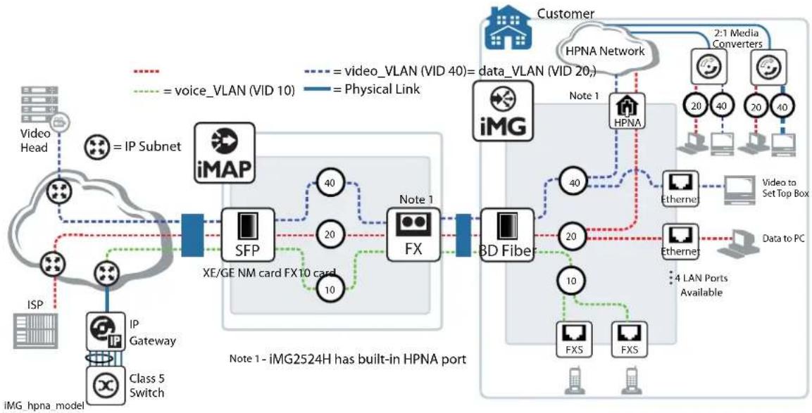
flowchart
graph TD
    subgraph_VideoHead["Video Head"]
        A["IP Subnet"] --> B["iMAP"]
        C["IP Gateway"] --> D["SFP"]
        E["Class 5 Switch"] --> F["Class 5 Switch"]
        G["ISP"] --> H["IP Gateway"]
        I["IP Gateway"] --> J["Class 5 Switch"]
    end

    subgraph_DataPort["Note 1 - iMG2524H has built-in HPNA port"]
        K["FX"] --> L["Note 1"]
        M["FXS"] --> N["Note 1"]
        O["FXS"] --> P["Note 1"]
        Q["FX"] --> R["Note 1"]
        S["FX"] --> T["Note 1"]
        U["FXS"] --> V["Note 1"]
        W["FXS"] --> X["Note 1"]
    end

    subgraph_Customer["Customer"]
        Y["HPNA Network"] --> Z["HPNA"]
        AA["HPNA"] --> AB["HPNA"]
        AC["HPNA"] --> AD["HPNA"]
        AE["HPNA"] --> AF["HPNA"]
        AG["HPNA"] --> AH["HPNA"]
        AI["HPNA"] --> AJ["HPNA"]
        AK["HPNA"] --> AL["HPNA"]
        AM["HPNA"] --> AN["HPNA"]
        AO["HPNA"] --> AP["HPNA"]
        AQ["HPNA"] --> AR["HPNA"]
        AS["HPNA"] --> AT["HPNA"]
        AU["HPNA"] --> AV["HPNA"]
        AW["HPNA"] --> AX["HPNA"]
        AY["Video to Set Top Box"] --> AZ["Etherne"]
        BA["Data to PC"] --> BB["Etherne"]
        BC["4 LAN Ports Available"] --> BD["Etherne"]
    end

    style VideoHead fill:#f9f,stroke:#333
    style DataPort fill:#ccf,stroke:#333
    style Customer fill:#cfc,stroke:#333
    style Customer fill:#fcc,stroke:#333
FIGURE 1-6 HPNA Sample Configuration
From a CLI configuration point of view, HPNA interface is managed as the other WAN/LAN copper/fiber interfaces. Only one hpna interface exists in the system and it is referred in CLI commands as hpna1.0.1.
Setting up the Gateway Interface Commands
HPNA interface supports trunk or access switch modes but does not support rate limiting and qos settings.
Specific test and provisioning commands are available for hpna1.0.1 interface to list the attached HPNA stations and performance capabilities.
1.13 Interface Commands
1.13.1 Interface Commands
This chapter provides an alphabetical reference of commands used to configure and display interfaces.
Table I-18: Interface Commands
| Commands |
| interface port |
| interface catv |
| interface vlan |
| show catv |
| show catv diagnostics |
| show interface |
| show interface brief |
| show interface status |
| show interface switchport |
| shutdown (config-if) |
| shutdown (config-if-catv) |
INTERFACE PORT
Syntax
interface
Description
This command selects one or more physical interfaces to configure.
The port can be a physical interface on the device - such as the Ethernet port - in which case it is possible to configure information specific to the devices - such as flowcontrol, protected mode, rate limiting, etc.
For ports, the interfaces are defined as follows.
| Device Port range Notes | ||
| iMG1500 port1.0.1 to port1.0.6 port1.0.6 is the WAN port | ||
| iMG2500 port1.0.1 to port1.0.5hpna1.0.1 | port1.0.5 is the WAN port | |
| iMG1400 port1.0.1,port1.0.2 and ,port1.0.5 are 10/100/1000. port1.0.3 and port1.0.4 are 10/100. | port1.0.6 is the WAN port |
Feature Interface Commands
Mode Global Configuration Mode
Release 4.1
Options
| Option Description Range | Default Value | ||
| The interfaces or ports to configure. An interface-list can be:- a switch port or ports, separated by a comma or dash,such as port1.0.1,port1.0.2 and port1.0.1-port1.0.5- a catv connection. (Refer to catv commands.)The specified interfaces must exist. | ALL | ALL | |
Note
Example The following example shows how to enter Interface mode to configure a port interface and the feature options in bold.
awplus(config)# interface port1.0.5 (this is the WAN port) awplus(config-if)# ?
do To run exec commands in config mode duplex Set duplex modes on the interface
egress-rate-limit Limit the amount of traffic egressing the interface end End current mode and down to privileged mode
exit End current mode and down to previous mode flowcontrol IEEE 802.3x Flow Control
help Description of the interactive help system
ingress-rate-limit Limit the amount of traffic ingressing the interface
interface Select an interface to configure mirror Port mirroring command
Setting up the Gateway Interface Commands
jumbo-frame Enable jumbo frame support (1000 Mbps speed only)
mls Multi-Layer Switch(L2/L3)
no Negate a command or set its defaults
quit End current mode and down to previous mode
shutdown Shutdown the selected interface
speed Set the link speed of an interface
switchport Set the switching characteristics of the Layer2 interface
INTERFACE CATV
Syntax interface catv
Description This command is used to enter the cable tv (catv) interface for the RF iMG models.
Feature Interface Commands
Mode Interface catv Configuration
Release 4.2
Options NA
Note NA
Example To enter the catv mode use the commands:
awplus(config)# interface catv awplus(config_if_catv)#
INTERFACE VLAN
Syntax interface
Description This command selects one or more vlans to configure.
The vlan list can be one or more vlans in which case it is possible to manipulate information such as the IP Address or the state of the DHCP Client.
Feature Interface Commands
Mode Global Configuration Mode
Release 4.1
Options
| Option Description Range | Default Value | ||
| The interfaces to configure. An interface-list can be:- an interface (e.g. vlan2)- a sub-interface (e.g. vlan2.1) | NA NA | ||
Note NA
Example The following example shows how to enter Interface mode to configure vlan1 and the featureoptions in bold.
awplus(config)# interface vlanl
access-group Add an access list to the VLAN access group do To run exec commands in config mode end End current mode and down to privileged mode exit End current mode and down to previous mode help Description of the interactive help system interface Select an interface to configure ip Internet Protocol (IP) no Negate a command or set its default quit End current mode and down to previous mode
awplus(config-if)# ip ? address IP address configuration commands dhcp Configure DHCP igmp Internet Group Management Protocol (IGMP)
SHOW CATV
Syntax
show catv
Description This command displays catv interface status.
Feature Interface Commands
Mode Interface catv Configuration
Release 4.2
Note NA
Example To display configuration and status information for catv on iMG1525RF use the command
awplus# show catv
RF Output:
Enabled
awplus# show catv diagnostics
Alarm State:
Off
awplus(config)# interface catv
awplus(config-if-catv)# ?
do To run exec commands in config mode
end End current mode and down to privileged mode
exit End current mode and down to previous mode
help Description of the interactive help system
no Negate a command or set its defaults
quit End current mode and down to previous mode
shutdown Disable cable TV RF interface
Example To display configuration and status information for catv on iMG1425RF and iMG1405RF use the command
awplus# show catv
RF Output: Enabled
Receive Signal: Not Detected
Vendor Name: Optomedia
Device Name: OND-5JA1-001
Device Revision: 02
Serial Number: 201S010516
Manufacturing Datecode: 12011900
Transceiver Type: CATV
RF Bandwidth: 47 - 1000 MHz
RF Receiver Wavelength: 1550 nm
Responsivity: 1.00 mA/mW
Min RF Tx Power: -
Max Optical Rx Power: 0.00 dBm
Min Optical Rx Power: -10.00 dBm
awplus# show catv diagnostics
| Status | Alarms | Warnings | |||||
| Reading | Alarm | Max | Min | Warn | Max | Min | |
| Temp: (Degrees C) | 60.273 | - | 80.000 | -0.004 | - | 75.000 | -0.004 |
| Vcc: (Volts) | 11.666 | - | 13.196 | 10.799 | - | 12.596 | 11.399 |
| PD Mon: (Volts) | 0.014 | Low | 2.235 | 0.088 | Low | 1.775 | 0.112 |
| RF Mon: (Volts) | 0.779 | Low | 2.047 | 1.256 | Low | 1.916 | 1.387 |
SHOW CATV DIAGNOSTICS
Syntax
show catv diagnostics
Description This command displays catv interface status.
Feature Interface Commands
Mode Interface catv Configuration
Release 4.2
Note NA
Example To display configuration and status information for catv use the command
awplus# show catv diagnostics
| Status | Alarms | Warnings | |||||
| Reading | Alarm | Max | Min | Warn | Max | Min | |
| Temp: (Degrees C) | -24.996 | Low | 80.000 | -0.004 | Low | 75.000 | -0.004 |
| Vcc: (Volts) | 3.374 | Low | 3.441 | 3.155 | Low | 3.393 | 3.298 |
| PD Mon: (Volts) | 1.072 | Low | 1.191 | 0.953 | Low | 1.144 | 1.001 |
| RF Mon: (Volts) | 1.311 | Low | 1.430 | 1.191 | Low | 1.382 | 1.239 |
SHOW INTERFACE
Syntax show interface [
Description This command displays interface configuration and status.
Feature Interface Commands
Mode User Exec and Privileged Exec Mode
Release 4.2
Options
| Option Description Range | Default Value | ||
| The interfaces to display information about. An interface list can be a switch port (e.g. port1.0.4) | ALL ALL | ||
Note This command now includes the HPNA port. Refer to the examples.
Example To display configuration and status information for interfaces port1.0.1 through port1.0.5, use the command:
awplus# show interface port1.0.1-port1.0.5
Interface port1.0.1
Link is DOWN, administrative state is UP
Address is 000c.2503.9a14
Description:
index 1 mtu N/A
flowcontrol disabled, configured duplex auto, configured speed auto
jumbo frame support is disabled
SNMP link-status traps: Disabled (Suppressed in 0 sec.)
Bandwidth Unknown
input packets 0, bytes 0, dropped 0, multicast packets 0
output packets 0, bytes 0, multicast packets 0 broadcast packets 0
Interface port1.0.2
Link is DOWN, administrative state is UP
Address is 000c.2503.9a14
Description:
index 2 mtu N/A
flowcontrol disabled, configured duplex full, configured speed 1000
jumbo frame support is disabled
SNMP link-status traps: Disabled (Suppressed in 0 sec.)
Bandwidth Unknown
input packets 0, bytes 0, dropped 0, multicast packets 0
output packets 0, bytes 0, multicast packets 0 broadcast packets 0
Interface port1.0.3
Link is DOWN, administrative state is UP
Address is 000c.2503.9a14
Description:
index 3 mtu N/A
flowcontrol disabled, configured duplex auto, configured speed auto
jumbo frame support is disabled
SNMP link-status traps: Disabled (Suppressed in 0 sec.)
Bandwidth Unknown
input packets 0, bytes 0, dropped 0, multicast packets 0
output packets 0, bytes 0, multicast packets 0 broadcast packets 0
Interface port1.0.4
Setting up the Gateway Interface Commands
Link is DOWN, administrative state is UP
Address is 000c.2503.9a14
Description:
index 4 mtu N/A
flowcontrol disabled, configured duplex auto, configured speed auto
jumbo frame support is disabled
SNMP link-status traps: Disabled (Suppressed in 0 sec.)
Bandwidth Unknown
input packets 0, bytes 0, dropped 0, multicast packets 0
output packets 0, bytes 0, multicast packets 0 broadcast packets 0
Interface port1.0.5
Link is UP, administrative state is UP
Address is 000c.2503.9a14
Description:
index 5 mtu N/A
current duplex full, current speed 1000, polarity N/A, flowcontrol both
jumbo frame support is disabled
configured duplex auto, configured speed auto
SNMP link-status traps: Disabled (Suppressed in 0 sec.)
Bandwidth Unknown
input packets 54153, bytes 3969372, dropped 0, multicast packets 2091
output packets 3170, bytes 385951, multicast packets 0 broadcast packets 311

Example To view the attributes for the HPNA port, input the following commands:
awplus# show interface hpna1.0.1

Interface hpna1.0.1
Link is UP, administrative state is UP
Address is 000c.2503.9a57
Description:
index 31 mtu N/A
current duplex N/A, current speed N/A, polarity N/A, flowcontrol both
configured duplex auto, configured speed auto
jumbo frame support is disabled
Protected switching mode is disabled
SNMP link-status traps: Disabled (Suppressed in 0 sec.)
Bandwidth Unknown
input packets 5415, bytes 770961, dropped 0, multicast packets 3476
output packets 288908693, bytes 1313253283, multicast packets 288897392 broadcast packets 9641

Example To view the attributes for the Wireless interface, input the following commands:
awplus# show interface dotllradio1.0.1

Interface dotllradio1.0.1
Link is UP, administrative state is UP
SSID1:
MAC address is e2:0d:da:0e:8c:00
IEEE 802.11n SSID:"iMG1405W-192"
Channel 11 (2.462 Ghz)
Bit Rate:144.4 Mbit/s
Rx packets 2034, bytes 176287, errors 0, dropped 0
Tx packets 1803, bytes 200018, errors 0, dropped 0
SSID2:
MAC address is f2:0d:da:0e:8c:00
Setting up the Gateway Interface Commands
IEEE 802.11n SSID:"Guest1-192"
Channel 11 (2.462 Ghz)
Bit Rate:144.4 Mbit/s
Rx packets 0, bytes 0, errors 0, dropped 0
Tx packets 1089, bytes 102454, errors 0, dropped 0
SSID3:
MAC address is 02:0d:da:0e:8c:00
IEEE 802.11n SSID:"Guest2-192"
Channel 11 (2.462 Ghz)
Bit Rate:144.4 Mbit/s
Rx packets 4634, bytes 396854, errors 0, dropped 0
Tx packets 2635127, bytes 2147483647, errors 0, dropped 0
SSID4:
MAC address is 12:0d:da:0e:8c:00
IEEE 802.11n SSID:"Guest3-192"
Channel 11 (2.462 Ghz)
Bit Rate:144.4 Mbit/s
Rx packets 0, bytes 0, errors 0, dropped 0
Tx packets 0, bytes 0, errors 0, dropped 0
SHOW INTERFACE BRIEF
Syntax show interface brief
Description This command displays brief interface, configuration, and status information, including provisioning information.
Feature Interface Commands
Mode User Exec and Privileged Exec Mode
Release 4.1
Options NA
Note NA
Example Example output from the show interface brief command
| awplus# show interface brief | ||
| Interface | Status | Protocol |
| port1.0.1 | admin up | down |
| port1.0.2 | admin up | down |
| port1.0.3 | admin up | down |
| port1.0.4 | admin up | down |
| port1.0.5 | admin up | up |
Table I-19: Parameters in the output of the show interface brief command
| Parameter Description | |
| Interface The name or type of interface. | |
| Status | The administrative state. This can be either admin up or admin down |
| Protocol | The link state. This can be either down, running, or provisioned |
SHOW INTERFACE STATUS
Syntax
show interface [
Description
This command displays the status of the specified interface or interfaces. Note that when no interface or interfaces are specified then the status of all interfaces on the switch are shown.
Feature Interface Commands
Mode Global Configuration Mode
Release 4.1
Options
| Option Description Range | Default Value | ||
| The ports to display information about. The port list can be separated by commas for each port or a dash (-) for a range of ports. | NA NA | ||
Note NA
Example To display the status of ports 1.0.1 to 1.0.5, use the commands: awplus# show interface port1.0.1-1.0.5 status
| Port | Name | Status | Vlan | Duplex | Speed | Type |
| port1.0.1 | notconnect | 1 | auto | auto | 1000BASE-T | |
| port1.0.2 | notconnect | 1 | auto | auto | 1000BASE-T | |
| port1.0.3 | notconnect | 1 | auto | auto | 1000BASE-T | |
| port1.0.4 | notconnect | 1 | auto | auto | 1000BASE-T | |
| port1.0.5 | notconnect | 1 | auto | auto | 1000BASE-T |
SHOW INTERFACE SWITCHPORT
Syntax
show interface switchport
Description
This command displays the interface status of the switchports. This includes the mode (access or trunk) and the VLAN configuration. Refer to Section 2 for more information.
Feature Interface Commands
Mode Global Configuration Mode
Release 4.1
Options NA
Note NA
Example To display the status of interface for all switchports, use the command:
awplus# show interface switchport
Interface name : port1.0.1
Switchport mode : access
Ingress filter : enable
Acceptable frame types : all
VLAN stacking port mode : customer
Default Vlan : 100
Configured Vlans : 100
Interface name : port1.0.5
Switchport mode : access
Ingress filter : enable
Acceptable frame types : all
VLAN stacking port mode : customer
Default Vlan : 100
Configured Vlans : 100
Interface name : port1.0.6
shutdown
no shutdown
Description
This command shuts down the selected interface. This administratively disables the link and takes the link down at the physical (electrical) layer.
Use the no variant of this command to disable this function and therefore to bring the link back up again.
Feature Interface Commands
Mode Interface Configuration
Release 4.2
Options NA
Note The catv interface is added in 4.2
Example The following example shows the use of the shutdown command to shut down port1.0.20.
awplus# configure terminal
awplus(config)# interface port1.0.20
awplus(config-if)# shutdown
Example The following example shows the use of the no shutdown command to bring up port1.0.12.
awplus(config)# interface port1.0.12
awplus(config-if)# no shutdown
Example The following example shows the use of the no shutdown command to bring up the catv interface on an iMG 1400.
awplus(config)# interface catv
awplus(config-if-catv)# no shutdown
SHUTDOWN (CONFIG-IF-CATV)
Syntax
shutdown
no shutdown
Description This command shuts down the selected catv interface.
Use the no variant of this command to disable this function and therefore to bring the catv interface into service
Feature Interface Commands
Mode Interface catv Configuration
Release 4.1.1
Options NA
Note NA
Example The following example shows the use of the no shutdown command to enable the catv interface.
awplus(config)# interface catv
awplus(config-if-catv)# no shutdown
1.14 Example Configuration
By following this section, the user should be able to start up the iMG and input commands at the various levels. The remaining sections of this document describe how Layer 2 and Layer 3 are configured for the iMG, as well as IGMP, Security, Network Management, and Voice Management.
To help the user work through these sections, the following figure shows the iMG2500 and iMG1500 in an example configuration that has data and video services. When appropriate, this example will be followed throughout the rest of this document for both example configurations and command examples.
Setting up the Gateway Example Configuration
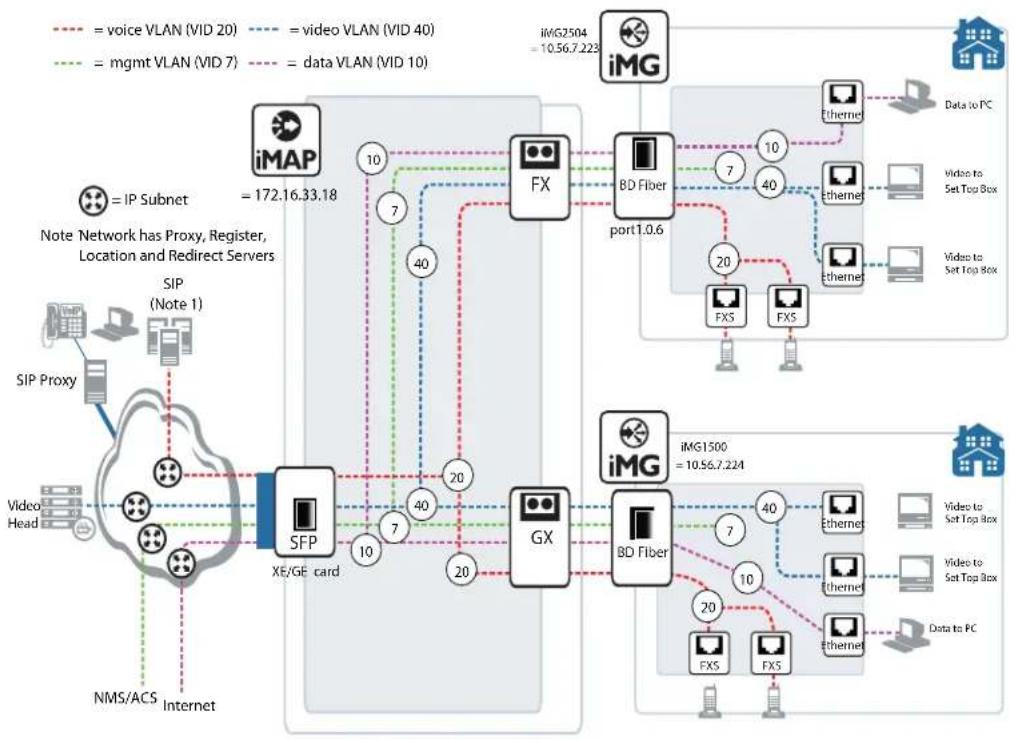
flowchart
graph TD
    A["iMG"] -->|= voice VLAN (VID 20)| B["FX"]
    A -->|= video VLAN (VID 40)| C["BD Fiber port1.0.6"]
    A -->|= mgmt VLAN (VID 7)| D["GX"]
    B -->|= voice VLAN (VID 20)| E["SFP"]
    C -->|= video VLAN (VID 40)| F["BD Fiber"]
    D -->|= mgmt VLAN (VID 7)| G["GX"]
    E --> H["Video Head"]
    F --> I["Video to Set Top Box"]
    G --> J["Video to Set Top Box"]
    K["iMAP"] -->|= IP Subnet| L["SIP Proxy"]
    M["iMG1500"] -->|= voice VLAN (VID 20)| N["FX"]
    O["iMG2504"] -->|= voice VLAN (VID 20)| P["BD Fiber port1.0.6"]
    Q["NMS/ACS"] --> R["Internet"]
    S["XE/GE card"] --> T["10"]
    U["XE/GE card"] --> V["10"]
    W["XE/GE card"] --> X["10"]
    Y["XE/GE card"] --> Z["10"]
    AA["XE/GE card"] --> AB["10"]
    AC["XE/GE card"] --> AD["10"]
    AE["XE/GE card"] --> AF["10"]
    AG["XE/GE card"] --> AH["10"]
    AI["XE/GE card"] --> AJ["10"]
    AK["XE/GE card"] --> AL["10"]
    AM["XE/GE card"] --> AN["10"]
    AO["XE/GE card"] --> AP["10"]
    AQ["XE/GE card"] --> AR["10"]
    AS["XE/GE card"] --> AT["10"]
    AU["XE/GE card"] --> AV["10"]
    AW["XE/GE card"] --> AX["10"]
    AY["VMG2504"] --> AZ["Data to PC"]
    BA["iMG1500"] --> BB["Video to Set Top Box"]
    BC["iMG2504"] --> BD["Video to Set Top Box"]
    BE["iMG2504"] --> BF["Data to PC"]
FIGURE 1-7 Example Configuration - iMG2500 and iMGI500
2. Routing
The Layer3 functionality of the iMG includes the following:
- Introduction
• Address Resolution Protocol (ARP)
• Domain Name System (DNS)
• Dynamic DNS (ddns)
• Internet Control Message Protocol (ICMP) - Checking IP Connections (ping and traceroute)
• Layer 3 Routing Command List
• IPv6 - IPv6 Command List
2.1 Introduction
This chapter describes how to configure IPv4 addressing and the protocols used to help IP function on your network.
As well as the familiar Internet, with uppercase "I", the term internet (with lowercase "i") can refer to any network (Local [LAN] or wide area network [WAN]) that uses the Internet protocol. This chapter concentrates on this definition-a generalized network that uses IP as its transport protocol.
2.1.1 Assigning an IP Address
To configure your device to perform IP routing (for example, to access the Internet) you need to configure IP. You also need to configure IP if you want to manage your device from any IP-based management process (such as SSH, Telnet, or SNMP).
Add an IP address to each of the interfaces that you want to process IP traffic.
You can configure an interface on your device with a static IP address, or with a dynamic IP address assigned using your device's DHCP client. Moreover, you can provision subinterfaces, allowing additional addressable entities. Both static and dhcp apply to these interfaces.
2.1.2 Static IP addresses
To add a static IP address to an interface, enter interface mode for the interface that you want to configure, then use the command:
awplus(config-if)# ip address <ip-addr/prefix-length>
where
For example, to give the interface vlan I an address of 192.168.10.10, with a class C subnet mask, use the command:
awplus (config)# interface vlan1
awplus(config-if)# ip address 192.168.10.10/24
2.1.3 DHCP dynamic addresses
When you use the DHCP client, it obtains the IP address and subnet mask for the interface, and other IP configuration parameters, from a DHCP server. To configure an interface to gain its IP configuration using the DHCP client, use the command:
awplus(config-if)# ip address dhcp
If an IP interface is configured to get its IP address and subnet mask from DHCP, the interface does not take part in IP routing until the IP address and subnet mask have been set by DHCP.
If you need to make a static entry in your DHCP server for the device, you need your device's MAC address, which you can display by using the command:
awplus# show interface
2.2 Address Resolution Protocol (ARP)
Address Resolution Protocol (ARP) is used by your device to dynamically learn the layer 2 address of devices in its networks. Most hosts also have a MAC physical address in addition to the assigned IP address. For Ethernet, this is a 6-byte, globally unique number: ARP enables your device to learn the physical address of the host that has a given IP address.
When your device needs to forward packets to a destination that it does not know the layer 2 address of, it broadcasts an ARP request to determine where to send the packet. The ARP request is a broadcast packet and includes the target IP address. All stations on the LAN receive this broadcast but only one host recognizes its own IP address. It replies, thereby giving your device its physical address.
Your device creates a dynamic ARP entry in its ARP cache, to record the IP address to physical address mapping (also called a binding). It uses that ARP entry to forward further packets to that address.
The ARP protocol is described in RFC 826, An Ethernet Address Resolution Protocol—or—Converting Network Protocol Addresses to 48 bit Ethernet Address for Transmission on Ethernet Hardware.
2.3 Domain Name System (DNS)
The Domain Name System allows you to access remote systems by entering human-readable device host names rather than IP addresses. DNS works by creating a mapping between a device name, such as “www.alliedtelesis.com”, and its IP address. These mappings are held on DNS servers. The benefits of DNS are that domain names:
- can map to a new IP address if the host's IP address changes
• are easier to remember than an IP address - allow organizations to use a domain name hierarchy that is independent of any IP address assignment
2.3.1 Domain name parts
Domain names are made up of a hierarchy of two or more name segments. Each segment is separated by a period. The format of domain names is the same as the host portion of a URL (Uniform Resource Locator). The first segment from the left is unique to the host, with each following segment mapping the host in the domain name hierarchy. The segment on the far right is a top-level domain name shared by many hosts.
2.3.2 Server hierarchy
A network of domain name servers maintains the mappings between domain names and their IP addresses. This network operates in a hierarchy that is similar to the structure of the domain names. When a local DNS server cannot resolve your request it sends the request to a higher level DNS server.
For example, to access the site “alliedtelesis.com”, your PC sends a DNS query to its local DNS server asking for the IP address matching alliedtelesis.com. If this address is already locally cached (following its recent use), the DNS server returns the IP address that matches alliedtelesis.com. If the DNS server does not have this address cached, it forwards the request upwards through the hierarchy of DNS servers until a DNS server can resolve the mapping. This means an often-used domain name is resolved quickly, while an uncommon or nonexistent domain may take longer to resolve or fail.
As well as the hierarchy of domain name servers accessible through the Internet, you can operate your own DNS server to map to private IP addresses within your network.
2.3.3 DNS Client
The Allied Telesis Gateway has a DNS Client that is enabled automatically when you add a DNS server to your device. This client allows you to use domain names instead of IP addresses when using commands on your device.
To add a DNS server to the list of servers that the device sends DNS queries to, use the command:
awplus(config)# ip name-server (IPv4)
To check the list of servers that the device sends DNS queries to, use the command:
awplus# show ip name-server (ipv4)
To add a default domain name used to append to DNS requests, use the command:
awplus(config)# ip domain-name <domain-name>
For example, to use DNS to match hostnames to your internal network "example.net", use the command:
awplus(config)# ip domain-name example.net
If you then use the command ping host2, your device sends a DNS request for host2.example.net. To check the domain name configured with this command, use the command:
awplus# show ip domain-name
Alternatively you can create a list of domain names that your device will try in turn by using the command:
awplus(config)# show ip domain-list <domain-name>
For example, to use DNS to match incomplete hostnames to the top level domains “.com”, and “.net”, use the commands:
awplus(config)# ip domain-list .com
awplus(config)# ip domain-list .net
If you then use the command ping alliedtelesis, your device sends a DNS request for alliedtelesis.com and if no match was found your device would then try alliedtelesis.net. To check the entries in the domain list, use the command:
awplus# show ip domain-list
To check the status of the DNS Client on your device, and the configured servers and domain names, use the command:
awplus# show hosts
2.3.4 Dynamic DNS (ddns)
Dynamic DNS (ddns) is a feature that allows remote hosts to connect to your home web server (such as a game server). This feature works with ddns providers (tzo and dyndds), which have the ip address/domain name association. (They are not limited to these two.) Whenever the IP address changes, the iMG informs the provider of this change. The provider then updates their dns servers; the remote hosts have their associations updated and can then access the (same) domain name using the new ip address.
Note: The ddns feature can be placed on a subvlan as well. Refer to Multiple IP Addresses on a Subinterface (subvlan).
2.3.5 DHCP options
When your device is using its DHCP client for an interface, it can receive the following DHCP options from the DHCP server:
Option 6 - a list of DNS servers. This list appends to the DNS servers set on your device with the ip name-server command.
Option 3 - routers
Option 15 - a domain name used to resolve host names. This option replaces the domain name set with the ip domain-name command.
Option 43 - ACS-TR-069 - This is for vendor-specific information, and contains the url for remote management.
Option 61 - This is the default client-id and is a combination of mac and vlan.
Refer to Dynamic Host Configuration Protocol (DHCP) for more information.
To configure DHCP client id option with a free form string, use the command:
awplus(config-if))# ip dhcp client client-id
To configure DHCP client id option with IAID-RFC3315, use the command:
awplus(config-if))# ip dhcp client client-id IAID F0F0ABC
To configure DHCP client request options, use the command:
awplus(config-if))# ip dhcp client request 6
2.4 Internet Control Message Protocol (ICMP)
The Internet Control Message Protocol (ICMP) allows networking devices to send information and control messages to other devices or hosts. Your device implements all non-obsolete ICMP functions.
The following table lists the ICMP messages implemented by your device.
Table 2-1: ICMP Messages
| ICMP Message Type Device Response | |
| Echo reply (0) This is used to implement the ping command. Your device sends out an echo reply in response to an echo request. | |
| Destination unreachable (3) | This message is sent when your device drops a packet because it did not have a route to the destination. |
| Redirect (5) | Your device issues this message to inform a local host that its target is located on the same LAN (no routing is required) or when it detects a host using a non-optimal route (usually because a link has failed or changed its status).For example, if your device receives a packet destined to its own MAC address, but with a destination IP address of another host in the local subnet, it returns an ICMP redirect to the originating host.ICMP redirects are disabled on interfaces on which local proxy ARP is enabled. |
| Echo request (8) This is related to echo replies. If your device receives an echo request, it sends an echo reply. If you enter the ping command, your device generates echo requests. | |
| Time to Live Exceeded (11) | If the TTL field in a packet falls to zero, your device sends this message. This occurs when there are too many hops in the path that a packet is traversing. |
ICMP messages are enabled on all interfaces by default. You can control the flow of ICMP messages across different interfaces using the Access Control List (ACL).
2.5 Checking IP Connections (ping and traceroute)
To verify connections between networks and network devices, use the ping (Packet Internet Groper) and trace route functions on your device.
2.5.1 Ping
Ping tests the connectivity between two network devices to determine whether each network device can “see” the other device. Echo request packets are sent to the destination addresses and responses are displayed on the console.
If you can ping the end destination, then the physical, Layer 2 and Layer 3 links are functioning, and any difficulties are in the network or higher layers.
If pinging the end destination fails, use traceroute to discover the point of failure in the route to the destination.
To ping a device, use the commandping (ipv4). Note that this command has options for IPv6 (refer to IPv6).
2.5.2 Traceroute
You can use traceroute to discover the route that packets pass between two systems running the IP protocol. Traceroute sends an initial UDP packets with the Time To Live (TTL) field in the IP header set starting at 1. The TTL field is increased by one for every subsequent packet sent until the destination is reached. Each hop along the path between two systems responds with a TTL exceeded packet (ICMP type 11) and from this the path is determined.
To use traceroute, use the command:
awplus# traceroute {<hostname>|<ipaddr>}
Note: This command has options for IPv6 (refer to traceroute ipv6).
2.6 Multiple IP Addresses on a Subinterface (subvlan)
2.6.1 Overview
The iMG can be configured in different ways to match the requirements of a service provider (or providers). The different services (voice, data, video, mgmt) usually exist on different subnets and are configured so that there is one VLAN/IP address per service. (This model is used in the configuration example in Example Configuration.)
There is also the case where a provider wishes to have only one vlan interface for all services. To make this possible, the network interface can have one VLAN (such as vlan1), with its associated IP address, and a sub-vlan interface, with each subvlan having its own IP address. These sub-vlan interfaces are named as vlan1.1, vlan1.2, etc. up to vlan1.31.
Refer to the following figure.
Note that for certain services are based on a single interface and so cannot use sub-vlans:
• IGMP
- NAT/Firewall
- Access List
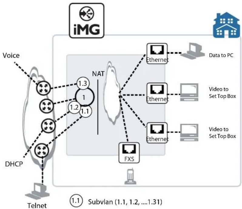
flowchart
graph TD
    A["iMG"] -->|Data to PC| B["Ethernet"]
    A -->|Video to Set Top Box| C["Ethernet"]
    A -->|Video to Set Top Box| D["Ethernet"]
    A --> E["FXS"]
    F["Voice"] --> G["DHCP"]
    G --> H["Telnet"]
    I["NAT"] --> J["1.3"]
    I --> K["1.2"]
    I --> L["1.1"]
    M["① 1 Subvlan (1.1, 1.2, ..., 1.31)"] --> N["1.1"]
FIGURE 2-1 Example Configuration using sub-vlans
2.6.2 Creating a sub-vlan
After creating the sub-vlan, the user inputs the interface command using the sub-vlan, and enters the (config-subif) level. Once at this level, the same types of commands are available as at the interface level. Following is an example sequence.
awplus(config-if)# interface vlan1.1 (vlan1 exists, creates additional ip interface) awplus(config-subif)# ip address dhcp (command is at the config-subif level) awplus(config-subif)# ip dhcp client request 3
2.6.3 Features that use subvlans
It is possible to use subinterfaces with the following features:
• IP Address management
- DHCP
- DDNS
- ping
- Route Tables
- TR69
Voip
- Telnet/SSH/http
The following features do not use subinterfaces (main interface only):
• IGMP
- NAT/Firewall and access lists (are all based on base interface)
The commands include subinterface parameters and outputs when they can be used.
2.7 Layer 3 Routing - iMG
2.7.1 Layer 3 Routing Command List
Following is an alphabetical reference of commands used to configure the following protocols:
- Address Resolution Protocol (ARP)
• Domain Name Service (DNS)
Table 2-2: Routing Commands
| Commands |
| add provider |
| add url |
| http |
| ip address |
| ip ddns update hostname |
| ip ddns update method |
| ip domain-name |
| ip name-server (IPv4) |
| ip route |
| ping (ipv4) |
| remove provider |
| remove url |
| show hosts |
| show ip ddns |
| show ip domain-list |
| show ip domain-name |
| show ip interface brief |
| show ip name-server (ipv4) |
| show ip route |
| show ip sockets |
| traceroute |
ADD PROVIDER
Syntax add provider {tzo | dyndns} username
Description This command selects the ddns provider and sets the username and password that is used to access the provider when the ip address for the domain name has been updated.
Feature IP Addressing and Protocol Commands
Mode Interface Configuration for a VLAN interface
Release 4.2
Options
| Option Description Range | Default Value | ||
| tzo | dyndns The ddns | providers. Refer to http://www.tzo.com and http://dyn.com/dns/ | NA NA | |
| username User-defined | name to access the provider. Refer to the ddns providers for conventions. | NA NA | |
| password User-defined | password to access the provider. Refer to the ddns providers for conventions. | NA NA |
Note NA
Example To add the ddns provider, use the following commands:
awplus# configure terminal
Enter configuration commands, one per line. End with CNTL/Z.
awplus(config)# awplus(config)# ip ddns update method tzo-method
awplus (DDNS-update-method) #http
awplus(DDNS-HTTP)# add provider tzo username my_name password my_password
ADD URL
Syntax add
Description This command adds the url that is created for the ddns service contact.
Feature IP Addressing and Protocol Commands
Mode Interface Configuration for a VLAN interface or a local loopback interface.
Release 4.2
Options NA
Note NA
Example To use this command, refer to the example
awplus# configure terminal
Enter configuration commands, one per line. End with CNTL/Z.
Awplus(config)# ip ddns update method tzo_method
Awplus(DDNS-update-method)# http
Awplus(DDNS-HTTP)# add http://myurl.com
HTTP
Syntax http
Description This command sets the protocol as http when associating a ddns method with a ddns provider.
Feature IP Addressing and Protocol Commands
Mode Interface Configuration for a VLAN interface or a local loopback interface.
Release 4.2
Options NA
Note NA
Example To use this command, refer to the example
awplus# configure terminal
Enter configuration commands, one per line. End with CNTL/Z.
Awplus(config)# ip ddns update method tzo-method
Awplus (DDNS-update-method) # http
Awplus(DDNS-HTTP)# add provider tzo username my_host password my_password
IP ADDRESS
Syntax
ip address
Description
This command sets a static IP address on an interface. To set the primary IP address on the interface, specify only ip address
The no variant of this command removes the IP address from the interface. You cannot remove the primary address when a secondary address is present.
Feature IP Addressing and Protocol Commands
Mode
Interface Configuration for a VLAN interface or a local loopback interface.
Release 4.1
Options
| Option Description Range | Default Value | ||
| The IPv4 address and prefix length you are assigning to the interface. | NA NA |
Note Only one method is allowed per interface.
Example To add the primary IP address 10.10.10.50/24 to the interface vlan7, use the following commands:
awplus# configure terminal
Enter configuration commands, one per line. End with CNTL/Z.
awplus(config)# interface vlan7
awplus(config-if)# ip address 10.10.10.50/24
IP DDNS UPDATE HOSTNAME
Syntax
ip ddns update hostname
Description
This command creates a user-defined hostname for the ddns provider. the ddns method. The command is also used when attaching the hostname to a (sub)interface.
The no variant of this Command deletes the hostname. This command will work only if the hostname is not associated with a (sub) interface.
Feature IP Addressing and Protocol Commands
Mode
Interface Configuration for a VLAN interface or a local loopback interface.
Release 4.2
Options
| Option Description Range | Default Value | ||
| User-defined hostname that is sent to the ddns provider.This hostname is used by remote hosts when they wish to access the local server. | NA NA |
Note NA
Example To create and attach a hostname to a (sub)interface, use the following commands.
awplus# configure terminal
Enter configuration commands, one per line. End with CNTL/Z.
awplus(config)# interface vlan1.1
awplus(config-subif)# ip ddns update method tzo_method
awplus(config-subif)# ip ddns update hostname example.name.com
awplus(config-subif)# do show ip ddns update
DDNS Update Method tzo_method >> Disabled
Provider None
User Name (null)
URL(non-specific) (null)
Interface brv1.1:1
Hostname example.name.com
IP DDNS UPDATE METHOD
Syntax
ip ddns update method <method_name>
ip ddns update hostname <hostname>
no ip ddns update method <method_name>
Description
This command creates a user-defined name for the ddns method. The command is also used when attaching the method name and hostname to a (sub)interface.
The no variant of this command deletes the method. This command will work only if the method is not associated with a (sub) interface.
Feature IP Addressing and Protocol Commands
Mode
Interface Configuration for a VLAN interface or a local loopback interface.
Release 4.2
Options
| Option Description Range | Default Value | ||
| method_name User-defined name for the ddns method. This name method must be associated with a (sub) interface to be activated. | NA NA | ||
| hostname User-defined hostname for the (sub)vlan NA NA | |||
Note NA
Example To create a method name, use the following commands. Note that the CLI is placed in the DDNS-update-method level.
awplus# configure terminal
Enter configuration commands, one per line. End with CNTL/Z.
awplus(config)# ip ddns update method tzo_method
awplus(DDNS-update-method)#
Example To attach a method to a (sub)interface a method name, use the following commands.
awplus# configure terminal
Enter configuration commands, one per line. End with CNTL/Z.
awplus(config)# interface vlan1.1
awplus(config-subif)# ip ddns update method tzo_method
awplus(config-subif)# ip ddns update hostname example.name.com
awplus(config-subif)# do show ip ddns update
DDNS Update Method tzo_method >> Disabled
Provider None
User Name (null)
URL(non-specific) (null)
Interface brv1.1:1
Hostname example.name.com
IP DOMAIN-NAME
Syntax
ip domain-name
no ip domain-name
Description
This command sets a default domain for the DNS. The DNS client appends this domain to incomplete host-names in DNS requests.
If there are no domains in the DNS list (created using the ip domain-list command) then your device uses the domain specified with this command. If any domain exists in the DNS list, then the device does not use the domain configured with this command.
When your device is using its DHCP client for an interface, it can receive Option 15 from the DHCP server. This option replaces the domain name set with this command. See Dynamic Host Configuration Protocol (DHCP) Introduction for more information about DHCP and DHCP options.
The no variant of this command removes the domain-name previously set by this command
Feature IP Addressing and Protocol Commands
Mode Global Configuration Mode
Release 4.1
Options
| Option Description Range | Default Value | ||
| Domain string, for example “company.com”. NA NA | |||
Note NA
Example To configure the domain name, enter the following commands:
awplus# configure terminal
Enter configuration commands, one per line. End with CNTL/Z.
ip domain-name company.com
IP NAME-SERVER (IPV4)
Syntax
ip name-server
Description
This command adds the IP address of a DNS server to the device's list of servers. The DNS client on your device sends DNS queries to devices on this list when trying to resolve a DNS hostname. Your device cannot resolve a hostname until you have added at least one server to this list. The iMG can support a maximum of 2 concurrent IPv4 DNS server addresses.
When your device is using its DHCP client for an interface, it can receive Option 6 from the DHCP server. This option appends the name server list with more DNS servers. See Dynamic Host Configuration Protocol (DHCP) Introduction for more information about DHCP and DHCP options.
The no variant of this command removes the DNS server from the list of servers.
Feature IP Addressing and Protocol Commands
Mode Global Configuration Mode
Release 4.1
Options
| Option Description Range | Default Value | ||
| The IP address to be advertised with the specified preference value. | NA NA | ||
Note NA
Example To allow your device to send DNS queries to a DNS server at 10.10.10.5, use the commands
awplus# configure terminal Enter configuration commands, one per line. End with CNTL/Z. ip name-server 10.10.10.5
IP ROUTE
Syntax
ip route
Description
This command adds a static route to the Routing Information Base (RIB). If this route is the best route for the destination, then your device adds it to the Forwarding Information Base (FIB). Your device uses the FIB to advertise routes to neighbors and forward packets.
The no variant of this command removes the static route from the RIB and FIB. The no variant of this command removes the DNS server from the list of servers.
Feature Routing Commands
Mode Global Configuration Mode
Release 4.1
Options
| Option Description Range | Default Value | ||
| The IPv4 address of the destination prefix with either a prefix length or a separate mask specified in one of the following formats:The IPv4 subnet address in dotted decimal notation followed by the subnet mask in dotted decimal notation.The IPv4 subnet address in dotted decimal notation followed by a forward slash, then the prefix length. | NA NA | ||
| The IPv4 address of the gateway device. NA NA | |||
| The interface that connects your device to the network.Enter the name of the VLAN or its VID. | NA NA | ||
| <1-255> The administrative distance for this route. For more information about setting administrative distances. | NA NA | ||
Note NA
Example To add the destination 192.168.3.0 with the mask 255.255.255.0 as a static route available through the device at "10.10.0.2", use the command:
awplus# configure terminal Enter configuration commands, one per line. End with CNTL/Z. ip route 192.168.3.0/24 10.10.10.2
PING (IPV4)
Syntax ping [ip]
Default This command sends a query to another IPv4 host (send Echo Request messages). The user can also specify which interface the ping requests should be sent on.
Feature IP Addressing and Protocol Commands
Mode User Exec and Privileged Exec Mode
Release 4.2
Options
| Option Description Range | Default Value | ||
| ip Specifies that IPv4 addresses are being used. NA NA | |||
| hostname The destination IP address or hostname. For IPv4 the format is A.B.C.D | NA NA | ||
| interface The vlan or vlan sub-interface (range) NA NA | |||
Note The ping command may take some time to complete. It can be interrupted at any time by pressing ctrl-c.
Example To ping a host, input the following:
awplus# ping 192.168.200.1
PING 192.168.200.1 (192.168.200.1): 56 data bytes
56 bytes from 192.168.200.1: icmp_seq=0 ttl=64 time=0.6 ms
56 bytes from 192.168.200.1: icmp_seq=1 ttl=64 time=0.4 ms
56 bytes from 192.168.200.1: icmp_seq=2 ttl=64 time=0.4 ms
56 bytes from 192.168.200.1: icmp_seq=3 ttl=64 time=0.4 ms
--- 192.168.200.1 ping statistics ---
4 packets transmitted, 4 packets received, 0% packet loss
round-trip min/avg/max = 0.4/0.4/0.6 ms
awplus# ping www.apple.com
PING www.apple.com (2.17.109.15): 56 data bytes
64 bytes from 2.17.109.15: seq=0 ttl=57 time=4.532 ms
64 bytes from 2.17.109.15: seq=1 ttl=57 time=3.690 ms
64 bytes from 2.17.109.15: seq=2 ttl=57 time=3.746 ms
64 bytes from 2.17.109.15: seq=3 ttl=57 time=3.631 ms
--- www.apple.com ping statistics ---
4 packets transmitted, 4 packets received, 0% packet loss
round-trip min/avg/max = 3.631/3.899/4.532 ms
REMOVE PROVIDER
Syntax remove provider
Description This command removes the ddns service contact that was previously created.
Feature IP Addressing and Protocol Commands
Mode Interface Configuration for a VLAN interface or a local loopback interface.
Release 4.2
Options NA
Note NA
Example To use this command, refer to the example
awplus# configure terminal
Enter configuration commands, one per line. End with CNTL/Z.
Awplus(config)# ip ddns update method tzo_method
Awplus(DDNS-update-method)# http
Awplus(DDNS-HTTP)# remove provider
REMOVE URL
Syntax remove url
Description This command removes the url that was previously created for the ddns service contact.
Feature IP Addressing and Protocol Commands
Mode Interface Configuration for a VLAN interface or a local loopback interface.
Release 4.2
Options NA
Note NA
Example To use this command, refer to the example
awplus# configure terminal
Enter configuration commands, one per line. End with CNTL/Z.
Awplus(config)# ip ddns update method tzo_method
Awplus(DDNS-update-method)# http
Awplus(DDNS-HTTP)# remove url
SHOW HOSTS
Syntax show hosts
Description This command shows the default domain, domain list, and name servers configured on your device.
Feature IP Addressing and Protocol Commands
Mode Privileged Exec Mode
Release 4.1
Options NA
Note NA
Example To display the default domain, use the command:
awplus# show hosts
awplus# show hosts
DNS default domain: AlliedTelesis
DNS domain list: company.com
domain Home
DNS Name Servers:
172.0.0.1
SHOW IP DDNS
Syntax show ip ddns [update]
Description This command shows the ddns configuration and whether any of the methods are attached to (sub)interfaces.
Feature IP Addressing and Protocol Commands
Mode Privileged Exec Mode
Release 4.2
Options
| Option Description Range | Default Value | |
| update In the output, displays the ddns attributes by method NA NA |
Note NA
Example To display the ddns attributes, use the commands:
awplus# show ip ddns
IP interface: vlan1
DDNS is disabled
IP interface: vlan1.1
Update Method is tzo_method
Provider None
Username
Hostname example.name.com
IP interface: vlan2
DDNS is disabled
IP interface: vlan7
DDNS is disabled
awplus# show ip ddns update
DDNS Update Method tzo_method >> Disabled
Provider None
User Name (null)
URL (non-specific) (null)
Interface brv1.1:1
Hostname example.name.com
SHOW IP DOMAIN-LIST
Syntax
show ip domain-list
Description
This command shows the domains configured in the domain list. The DNS client uses the domains in this list to append incomplete hostnames when sending a DNS enquiry to a DNS server.
Feature IP Addressing and Protocol Commands
Mode Privileged Exec Mode
Release 4.1
Options NA
Note NA
Example To display the list of domains in the domain list, use the command
awplus# show ip domain-list
DNS domain list:
domain Home
SHOW IP DOMAIN-NAME
Syntax
show ip domain-name
Description
This command shows the default domain configured on your device. When there are no entries in the DNS list, the DNS client appends this domain to incomplete hostnames when sending a DNS enquiry to a DNS server.
Feature IP Addressing and Protocol Commands
Mode Privileged Exec Mode
Release 4.1
Options NA
Note NA
Example To display the list of domains in the domain list, use the command
awplus# show ip domain-name
DNS default domain Allied Telesis
SHOW IP INTERFACE BRIEF
Syntax show ip interface brief
Description This command displays brief information about interfaces and the IP addresses assigned to them.
Feature IP Addressing and Protocol Commands
Mode Privileged Exec Mode
Release 4.2
Options NA
Note NA
Example To show the IP addresses assigned to the device, use the command
awplus# show ip interface brief
| Interface | IP-Address | Status | Protocol |
| vlan1 | unassigned | admin up | down |
| vlan1.1 | unassigned | admin up | down |
| vlan2 | unassigned | admin up | running |
| vlan7 | unassigned | admin up | down |
| vlan10 | unassigned | admin up | down |
| vlan20 | unassigned | admin up | down |
| vlan40 | unassigned | admin up | down |
SHOW IP NAME-SERVER (IPV4)
Syntax
show ip name-server
Description
This command displays the list of DNS servers your device sends DNS requests to. On the iMG these server addresses can be set statically using the ip name-server (IPv4) command, or dynamically using the DHCP option 6.
The iMG supports up to 2 concurrent IPv4 and 2 concurrent IPv6 DNS server addresses (so a combined maximum of 4). Note that setting a static server address discards any dynamically set DNS server addresses. So this command will show either static or dynamic DNS server addresses - but not both at once
Feature IP Addressing and Protocol Commands
Mode Privileged Exec Mode
Release 4.1
Options N/A
Note NA
Example To display the list of DNS servers that your device sends DNS requests to, use the command
awplus# show ip name-server
DNS Name Servers:
172.0.01
SHOW IP ROUTE
Syntax show ip route
Description This command shows the ip route to display the current state of the routing table.
Typically, route entries are composed of the following elements
• * c o d e
- * a second label indicating the sub-type of the route
• * network or host ip address
• * administrative distance and metric
- * nexthop ip address
• * outgoing interface name
- This route is the same as the other OSPF route explained above; the main difference is that it is a Type 2 External OSPF route.
Feature Routing Commands
Mode Privileged Exec Mode
Release 4.1
Options NA
Note NA
Example To display the OSPF routes in the FIB, use the command. If any VRF is configured, it will display routes defined for that VRF.:
awplus# show ip route ospf
Example To display the routes in the context of a VRF instance "red" in the FIB, use the command:
awplus# show ip route vrf red
Example To display all routes in the FIB, including routes for all VRF instances if any VRF is configured, use the command:
awplus# show ip route
| Destination | Mask | NextHop | Interface | Protocol |
| 172.0.0.0 | 255.255.0.0 | 0.0.0.0 | vlan1 | INTERFACE |
| 0.0.0.0 | 0.0.0.0 | 172.0.0.1 | vlan1 | DHCP |
SHOW IP SOCKETS
Syntax show ip sockets
Description This command displays informations about the IP sockets that are present on the device. It includes TCP, UDP listen sockets, displaying associated IP address and port. When a TCP session is established this is displayed including the remote IP address and port and the state of the session.
Feature Routing Commands
Mode Privileged Exec Mode
Release 4.2
Options NA
Note NA
Example To display the IP sockets, use the command:
awplus # show ip sockets
Active Internet connections (servers and established)
| Proto | Recv-Q | Send-Q | Local Address | Foreign Address | State |
| tcp | 0 | 0 | 127.0.0.1:54321 | 0.0.0.0:* | LISTEN |
| tcp | 0 | 0 | 0.0.0.0:44401 | 0.0.0.0:* | LISTEN |
| tcp | 0 | 0 | 0.0.0.0:30005 | 0.0.0.0:* | LISTEN |
| tcp | 0 | 0 | :::80 | :::* | LISTEN |
| tcp | 0 | 0 | :::22 | :::* | LISTEN |
| tcp | 0 | 0 | :::23 | :::* | LISTEN |
| tcp | 0 | 0 | ::ffff:172.32.4.203:22 | ::ffff:10.17.90.132:3905 |
ESTABLISHED
| udp | 0 | 0 0.0.0.0:161 | 0.0.0.0:* |
| udp | 0 | 0 0.0.0.0:162 | 0.0.0.0:* |
| udp | 0 | 480 172.32.3.203:50606 | 0.0.0.0:* |
| udp | 50688 | 0 172.32.3.203:50607 | 0.0.0.0:* |
| udp | 0 | 0 0.0.0.0:67 | 0.0.0.0:* |
| udp | 0 | 0 172.32.3.203:5060 | 0.0.0.0:* |
| udp | 0 | 0 127.0.0.1:53201 | 0.0.0.0:* |
| udp | 0 | 0 :::54274 | ::::* |
| udp | 0 | 0 :::53 | ::::* |
| udp | 0 | 0 :::19401 | ::::* |
| raw | 0 | 0 0.0.0.0:2 | 0.0.0.0:* |
TRACEROUTE
Syntax traceroute {
Description This command traces the route to the specified IPv4 host.
Feature IP Addressing and Protocol Commands
Mode User Exec and Privileged Exec Mode
Release 4.1
Options
| Option Description Range | Default Value | ||
| The destination IPv4 address. The IPv4 address uses the format A.B.C.D. | NA | NA | |
| The destination hostname. | NA | NA | |
Note The traceroute command may take some time to complete. It can be interrupted at any time by pressing ctrl-c.
Example
awplus# traceroute 10.10.0.5
2.8 IPv6
2.8.1 Overview
IPv6 is the next generation of the Internet Protocol (IP). It has primarily been developed to solve the problem of the eventual exhaustion of the IPv4 address space, but also offers other enhancements. IPv6 addresses are 16 bytes long, in contrast to IPv4's 4 byte addresses. Other features of IPv6 include:
- Address structure improvements:
- globally unique addresses with more levels of addressing hierarchy to reduce the size of routing tables
• autoconfiguration of addresses by hosts - improved scalability of Multicast routing by adding a "scope" field to Multicast addresses
- Removes the need for packet fragmentation en-route, by dynamic determination of the largest packet size that is supported by every link in the path. A link's MTU (Maximum Transmission Unit) must be at least 1280 bytes, compared with 576 bytes for IPv4.
- Includes a Traffic Class that allow packets to be labeled with an appropriate priority. If the network becomes congested, the lowest priority packets are dropped.
- Includes Flow labels that indicate to intermediate switches and routers that packets are part of a flow, and that a particular flow requires a particular type of service. This feature enables, for example, real-time processing of data streams. It also increases routing speed because the forwarding router need only check the flow label, not the rest of the header. The handling indicated by the flow label can be done by the IPv6 Hop-by-Hop header, or by a separate protocol such as RSVP.
- Mandatory authentication and data integrity protocols through IPsec. IPsec is optional in IPv4.
2.8.2 IPv6 Addresses and Prefixes
IPv6 addresses are hexadecimal, and are made up of eight pairs of octets separated by colons. An example of a valid address is 2001:0db8:0000:0000:0260:0000:97ff:64aa. In the interests of brevity, addresses can be abbreviated in two ways:
- Leading zeros can be omitted, so this address can be written as 2001:db8:0:0:260:0:97ff:64aa.
- Consecutive zeros can be replaced with a double colon, so this address can be written as 2001:db8::260:0:97ff:64a. Note that a double colon can replace any number of consecutive zeros, but an address can contain only one double colon.
Like IPv4 addresses, a proportion of the left-most bits of the IPv6 address can be used to indicate the subnet, rather than a single node. This part of the address is called the prefix. Prefixes provide the equivalent functionality to a subnet mask in IPv4, allowing a subnet to be addressed, rather than a single node. If a prefix is specified, the IPv6 address is followed by a slash and the number of bits that represent the prefix. For example, 2001::/16 indicates that the first 16 bits (2001) of the address 2001:0:0:0:0:0:0 represent the prefix.
Like IPv4 addresses, IPv6 addresses are attached to interfaces.
2.8.3 Address Types
IPv6 supports the following address types:
- unicast
- Multicast
- Anycast
2.8.3.1 unicast addresses
A unicast address is attached to a single interface and delivers packets only to that interface. The following special addresses have been defined:
- IPv4-compatible and IPv4-mapped addresses. IPv4-compatible addresses are used to tunnel IPv6 packets across an IPv4 network. IPv4-mapped addresses are used by an IPv6 host to communicate with an IPv4 host. The IPv6 host addresses the packet to the mapped address.
Note: Tunneling of IPv6 through IPv4 or vice-versa is not supported in 4.2
- Link-local addresses can be used on the local network on which the interface is attached. The link-local prefix is fe80::/10. Different interfaces on a device may have the same link-local address. The iMG will automatically generate a link-local address for all interfaces that are using IPv6. Commands entered to configure link-local addresses that match any automatically generated link-local addresses by the switch will not be executed.
- Site-local - These are the equivalent of IPv4 private addresses. These cannot transmit from one site to another site without the use of a global IPv6 address.
- Global - These are the equivalent of public IPv4 addresses. Global addresses can be routed publicly in the Internet. Any device or site that wishes to transmit packets to another site must be uniquely identified with a global address.
2.8.3.2 Multicast addresses
IPv6 Multicast addresses provide the equivalent functionality to broadcast addresses in IPv4. Broadcast addresses are not supported in IPv6. A Multicast address identifies a group of interfaces, and packets are sent to all interfaces in that group.
Among the special addresses that have been defined are addresses that allow Multicasting to:
• All interfaces on a particular host (ff01::1)
• All nodes on a local network (ff01::2)
• All routers on the local link (ff02::2)
- All routers on the local site (ff05::2).
2.8.3.3 Anycast addresses
An anycast address is a unicast address that is attached to more than one interface. If a packet is sent to an anycast address it is delivered to the nearest interface with that address, with the definition of “nearest” depending on the protocol used for routing. If the protocol is RIPv6, the nearest interface is the one that is the shortest number of hops away.
Anycast addresses can be assigned to routers only, and packets cannot originate from an anycast address. A router must be configured to know that it is using an anycast address because the address format cannot be distinguished from that of a unicast address.
Only one anycast address has been predefined: the subnet-router address. The subnet-router address sends messages to the nearest router on a subnet and consists of the subnet's prefix followed by zeros.
Note: Assignment of anycast addresses is not supported in 4.2.
2.8.4 IPv6 Headers
The basic unit of data sent through an internet is called a packet in IPv6. A packet consists of a header followed by the data. The following table lists the IPv6 fields.
Table 2-3: IPv6 Field Descriptions
| Field Function | |
| Ver Version of the IP protocol that | created the packet. For IPv6, this field has a value of 6. |
| Differentiated Services 8-bit value that | contains the 6-bit DSCP and is used to prioritize traffic as part of a Quality of Service system. For more information, see “Differentiated Services Architecture” on page60.4. Additional information can be found in RFC 2474, Definition of the Differentiated Services Field (DS Field) in the IPv4 and IPv6 Headers. |
| Flow Label 20-bit value that indicates the data flow to which this packet belongs. This flow may be handled in a particular way. | |
| Payload Length Length of the user data portion of the packet. If the data payload is larger than 64 kB, the length is given in the optional “Jumbo Payload” header and the Payload Length header is given a value of zero. | |
| Next Header Number that indicates the type of header that immediately follows the basic IP header. This header type may be an optional IPv6 extension header, a relevant IPv4 option header, or another protocol, such as TCP or ICMPv6. The IPv6 extension header values are: - 0 (Hop-by-Hop Options Header) - 43 (IPv6 Routing Header) - 44 (IPv6 Fragment Header) - 50 (Encapsulating Security Payload) - 51 (IPv6 Authentication Header) - 59 (No Next Header) - 60 (Destination Options Header) | |
| Hop Limit Field that is the equivalent of the IPv4 Time To Live field, measured in hops. | |
Table 2-3: IPv6 Field Descriptions
| Field Function | |
| Source IP address 128-bit IPv6 address of the sender. | |
| Destination IP address 128-bit IPv6 address of the recipient. | |
| Optional extension headers Headers for less-frequently used information. | |
| User data Payload. | |
2.8.5 Basic IPv6 Header Structure
The headers contain information necessary to move the packet across the internet. They must be able to cope with missing and duplicated packets as well as possible fragmentation (and reassembly) of the original packet.
IPv6 headers are twice as long as IPv4 headers (40 bytes instead of 20 bytes) and contain four times the address space size (128 bits instead of 32 bits).
They no longer contains the header length, identification, flags, fragment offset, and header checksum fields. Some of these options are placed in extension headers. The Time To Live field is replaced with a hop limit, and the IPv4 Type of Service field is replaced with a Differentiated Services field. The Differentiated Services field contains the DSCP bits, used in a Quality of Service (QoS) regime. The following table explains IPv4 header fields that changed in IPv6.
Table 2-4: IPv6 Header Structure
| Field Function | |
| Type of Service The type of service | that a connection should receive is indicated in IPv6 by the Flow Label field in the IPv6 header. |
| Fragmentation information (the Identification field, the Flags field and the Fragment Offset field) | In most cases fragmentation does not occur in IPv6. If it does, packets are fragmented at their source and not en route. Therefore, the fragmentation information is contained in an extension header to reduce the size of the basic IPv6 header. |
| Header Checksum This option has | not been provided in IPv6. This is because transport protocols implement checksums and because of the availability of the IPsec authentication header (AH) in IPv6. |
| Options Extension headers handle | all the optional values associated with IPv6 packets. The biggest advantage of this scheme is that the size of the basic IP header is a constant. |
2.8.5.1 Extension Headers
IPv6 implements many of the less commonly used fields in the IPv4 header (or their equivalents) as extension headers, which are placed after the basic IPv6 header. The length of each header must be a multiple of 8 bytes.
The first extension header is identified by the Next Header field in the basic IPv6 header. Any subsequent extension headers are identified by an 8-bit "Next Header" value at the beginning of the preceding extension header.
IPv6 nodes that originate packets are required to place extension headers in a specific order:
- The basic IPv6 header. This must come immediately before the extension headers.
- The Hop-by-Hop header. This specifies options that must be examined by every node in the routing path.
Routing IPv6
- A Destination Options header. This is used to specify options to be processed by the first destination or final destination. The destination options header is the only extension header that may be present more than once in the IPv6 packet.
- The Routing header. This enables a static path to be specified for the packet, if the dynamically-determined path is undesirable.
- The Fragment header. This indicates that the source node has fragmented the packet, and contains information about the fragmentation.
- The Authentication header (AH). This verifies the integrity of the packet and its headers
- The Encapsulating Security Payload (ESP) header. This encrypts a packet and verifies the integrity of its contents.
- The Upper Layer Protocol header. This indicates which protocol a higher layer (such as the transport layer) is to process the packet with (for example, TCP).
2.8.6 The Internet Control Message Protocol (ICMPv6)
The Internet Control Message Protocol, ICMPv6, provides a mechanism for error reporting and route discovery and diagnostics. It also conveys information about Multicast group membership, a function that is carried out by the Internet Group Management Protocol (IGMP) in IPv4, and performs address resolution, which the Address Resolution Protocol (ARP) performs in IPv4.
Significant aspects of ICMPv6 include neighbor discovery, which enables one device in a network to find out about other nearby devices; and stateless address autoconfiguration, which allows a device to dynamically determine its own IPv6 address.
ICMPv6 is also used to support the Ping v6 (Packet Internet Groper) and Trace route v6 functions that are used to verify the connections between networks and network devices. Ping is used to test the connectivity between two network devices to determine whether each network device can “see” the other device. Trace route is used to discover the route used to pass packets between two systems running the IP protocol.
Both of these functions operate almost identically in IPv4 and IPv6. Refer to the ping ipv6 command.
2.8.6.1 Neighbor Discovery
Neighbor discovery is an ICMPv6 function that enables a router or a host to identify other devices on its links. This information is then used in address autoconfiguration, to redirect a node to use a more appropriate router if necessary, and to maintain reach ability information with its neighbors.
The IPv6 Neighbor Discovery protocol is similar to a combination of the IPv4 protocols ARP, ICMP Router Discovery and ICMP Redirect.
The following table describes packet types involved with neighbor discovery.
Table 2-5: IPv6 Neighbor Discovery Packet Types
| Packet Type Description | |
| router solicitation Packet in which a host sends out a request for routers to generate advertisements. | |
| router advertisement Allows routers to advertise their presence and other network parameters. A router sends an advertisement packet in response to a solicitation packet from a host. | |
| neighbor solicitation Packet in which a node sends a packet to determine the link layer address of a neighbor or to verify that a neighbor is still active. | |
| neighbor advertisement A response to a neighbor solicitation packet. These packets are also used to notify neighbors of link layer address changes. | |
Table 2-5: IPv6 Neighbor Discovery Packet Types
| Packet Type Description | |
| redirect Informs hosts of a better first hop. | |
To comply with Section 6.2.1 of RFC 2461, IPv6 Neighbor Discovery, the router does not generate router advertisements by default. The following table explains packet types and services.
Table 2-6: IPv6 Neighbor Discovery Packet Types
| Packet Type Description | |
| address resolution A method for carrying out address autoconfiguration, and is achieved using the Neighbor Solicitation Message and the Neighbor Advertisement Message. | |
| router and prefix discovery On connection to a link, a node needs to know the address of a router that the node can use to reach the rest of the world. The node also needs to know the prefix (or prefixes) that define the range of IP addresses on its link that it can reach without going through a router.Routers use ICMP to convey this information to hosts, by means of router advertisements. The message may have an option attached (the source link address option), which enables the receiving node to respond directly to the router, without performing a neighbor solicitation. | |
| immediate information The configuration of a router includes a defined frequency at which unsolicited advertisements are sent. If a node wants to obtain information about the nearest router immediately, rather than waiting for the next unsolicited advertisement, the node can send a router solicitation message.Each router that receives the solicitation message sends a router advertisement specifically to the node that sent the solicitation. | |
| redirection If a node is aware of more than one router that it can use to connect to wider networks, the router to which it sends packets by default does not always represent the most desirable route.ICMPv6 uses the redirect packet to communicate a more effective path to the node. | |
| Neighbor Unreachability Detection (NUD) | A node may issue solicitation requests to determine whether a path is still viable, or may listen in on acknowledgement packets of higher layer protocols, such as TCP. If the node determines that a path is no longer viable, it attempts to establish a new link to the neighbor, or to re-establish the previous link. NUD can be used between any two devices in the network, independent of whether the devices are acting as hosts or routers. |
2.8.7 Stateless Address Autoconfiguration (SLAAC)
Stateless address autoconfiguration allows an IPv6-aware device to be plugged into a network without manual configuration with an IP address. This plug and play functionality results in networks that are easier to set up and modify, and simplifies the process of shifting to use a new Internet Service Provider (ISP).
Stateless address autoconfiguration is achieved in a series of steps. Routers and hosts perform the first three steps, which auto configure a link-local address. A global address is auto configured in the last three steps, which only hosts perform.
2.8.7.1 On the Router or Host
- During system start-up, the iMG begins autoconfiguration by generating a link-local address for the interface. A link-local address is formed by adding the interface ID to the link-local prefix fe80::/10 (reference RFC 3513).
Note: Different interfaces on an iMG may have the same link-local address. The switch will automatically generate a link-local address for all interfaces that are using IPv6. Commands entered to configure link-local addresses that match any automatically generated link-local addresses by the switch will not be executed. Enter the show ipv6 interface brief command to display automatically generated link-local addresses. Automatically generated link-local addresses contain the last six hexadecimal numbers of the MAC address for a given interface.
- The node then transmits a neighbor solicitation message to this address. If the address is already in use, the node that the address belongs to replies with a neighbor advertisement message. The autoconfiguration process stops and manual configuration of the node is then required.
- If no neighbor advertisement is received, the node concludes that the address is available and assigns it to the chosen interface.
2.8.7.2 On the Host
I. The node then sends one or more router solicitations to detect if any routers are present. Any routers present responds with a router advertisement.
If no router advertisement is received, the node tries to use DHCP to obtain an address and other configuration information. If no DHCP server responds, the node continues using the link-level address
If a router advertisement is received, this message informs the node how to proceed with the auto configuration process. The prefix from the router advertisement, if received, is added to the link-level address to form the global unicast IP address.
- This address is then assigned to the network interface.
If routers are present, the node continues to receive router advertisements. The node updates its configuration when there are changes in the router advertisements.
2.8.8 IPv6 Routing
Routing in IPv6 is almost identical to IPv4 routing under CIDR, except that the addresses are 128-bit IPv6 addresses instead of 32-bit IPv4 addresses.
2.8.9 Integration of IPv4 and IPv6
IPv6 has been designed in such a way that a smooth transition from IPv4 is possible. The most effective way to ensure this is to use a dual IP stack. A node configured as a dual stack system has both a 128-bit IPv6 address and a 32-bit IPv4 address, and so can communicate with nodes running IPv4 and those running IPv6.
2.8.10 Enabling IPv6 on the iMG
This section describes the iMG's support for IPv6, and how to configure IPv6 on the iMG.
2.8.10.1 Enabling IPv6
The iMG's implementation of IPv6 is disabled by default on all interfaces. To enable IPv6 on an interface, use the ipv6 enable (config-if) or ipv6 address (config-if) command. To display information about IPv6 settings, use the show ipv6 interface brief command. Because the iMG implements IPv6 as a dual stack, implementing IPv6 does not affect IPv4 functionality.
IPv6 packet forwarding is also disabled by default. To enable IPv6 packet forwarding, use the ipv6 forwarding (config) command.
2.8.10.2 IPv6 Stateless Address Autoconfiguration (SLAAC)
The iMG's implementation of IPv6 supports SLAAC. To enable IPv6 SLAAC on an interface, use the ipv6 address (config-if) command with the autoconfig option. SLAAC uses the EUI-64 algorithm to populate the least significant 64 bits of the global unicast address. ipv6 address autoconfig automatically configures both an IPv6 link-local address and an IPv6 global unicast address, and also enables IPv6 processing on the interface.
2.8.10.3 IPv6 Link-local Addresses
The iMG's implementation of IPv6 supports enabling of IPv6 on an interface with only an IPv6 link-local addresses (i.e. no global unicast address) for communications within the local subnetwork. Routers do not forward packets to link-local addresses. To enable this mode, use the ipv6 enable (config-if) command. ipv6 enable automatically configures an IPv6 link-local address on the interface and enables IPv6 processing on the interface.
2.8.11 IPv6 and IPv4 on the iMG
In 4.2 both IPv4 and IPv6 can be configured on the iMG. The services each can support are as follows:
- Management of the iMG (using ssh, telnet, SNMP, HTTP and TR69) is by means of IPv4 only.
- VoIP support is by means of IPv4 only. (The SIP & MGCP applications do not currently support IPv6).
- Streaming video is by means of IPv4 (using IGMP) only.
- Routed IPv4 data, i.e. IPv4 internet using NAT.
- Routed IPv6 data, i.e. IPv6 internet using GUAs (globally unique addresses) on all interfaces. Note that IPv6 NAT is not supported on the iMG.
- Bridged data (layer 2). In this case the iMG is used simply as a layer 2 switch, and layer 3 (IPv4 and/or IPv6) packets are switched transparently by the iMG.
2.8.12 IPv6 Command List
Table 2-7: IPv6 Commands
| Commands |
| ipv6 address (config-if) |
| ipv6 enable (config-if) |
| ipv6 forwarding (config) |
| ip name-server (config) - IPv6 |
| ipv6 nd dad-attempts (config-if) |
| ipv6 nd managed-config-flag (config-if) |
| ipv6 nd minimum-ra-interval (config-if) |
| ipv6 nd other-config-flag (config-if) |
| ipv6 nd ra-interval (config-if) |
| ipv6 nd rs-attempts (config-if) |
| ipv6 nd rs-delay (config-if) |
| ipv6 nd rs-interval (config-if) |
| ipv6 nd suppress-ra (config-if) |
| ipv6 route (config) |
| ping ipv6 |
| show ip name-server (ipv6) |
| show ipv6 forwarding |
| show ipv6 general-prefix |
| show ipv6 interface brief |
| show ipv6 interface verbose |
| show ipv6 neighbors |
| show ipv6 route |
| traceroute ipv6 |
IPV6 ADDRESS (CONFIG-IF)
Syntax
ipv6 address <delegated-prefix-name> 0:0:0:<bits>::/<dp-len> eui-64
ipv6 address <ipv6-prefix>/<prefix-len> eui-64 [default]
ipv6 address <ipv6-addr>/<prefix-len> [default]
ipv6 address autoconfig [default]
no ipv6 address <delegated-prefix-name> 0:0:0:<bits>::/<dp-len> eui-64
no ipv6 address <ipv6-prefix>/<prefix-len> eui-64 [default]
no ipv6 address <ipv6-addr>/<prefix-len> [default]
no ipv6 address autoconfig [default]
Description Use this command to set the IPv6 address of a VLAN interface and enable IPv6 on the interface. Use the no variant of this command to remove the address assignment.
Feature IPv6 Commands
Mode Interface Mode
Release 4.2
Options
| Option Description Range | Default Value | ||
| delegated-prefix-name | Name of the delegated prefix from which to derive the dp-len high-order bits of the address prefix (high-order 64 bits of the address). | NA NA | |
| bits The low-order bits of the address prefix (high-order 64 bits of the address). | 0-FFFF NA | ||
| dp-len The length of delegated prefix delegated-prefix-name I-64 NA | |||
| eui-64 The EUI-64 algorithm will be used to derive the low-order 64 bits of the IPv6 address from the interface MAC address. | NA NA | ||
| ipv6-prefix An IPv6 address prefix of the form X:X:X:: NA NA | |||
| ipv6-addr An IPv6 address of the form X:X:X::X NA NA | |||
| prefix-len Prefix length of the address. For Ethernet interfaces this should always be 64. | 64 NA | ||
| default | Indicates that this interface will be used to derive the default IPv6 route dynamically from RA (router advertisement) messages. | NA NA | |
Note All interfaces default to IPv6-disabled with no IPv6 address.
If the 'default' option is specified on multiple IPv6 interfaces, the last interface so specified is used for the default route.
The 'default' option cannot be specified if a static IPv6 default route has been configured on the iMG.
Example
awplus(config)# interface vlan1 awplus(config-if)# ipv6 address 2001:0db8::a2/64
IPV6 ENABLE (CONFIG-IF)
Syntax ipv6 enable no ipv6 enable
Description Use this command to enable an IPv6 interface with only a link local address.
Feature IPv6 Commands
Mode Interface Config
Release 4.2
Options NA
Note All interfaces default to IPv6 disabled with no IPv6 address.
Example
awplus(config)# interface vlan1 awplus(config-if)# ipv6 enable
Routing IPv6
IPV6 FORWARDING (CONFIG)
Syntax
ipv6 forwarding
no ipv6 forwarding
Description
Use this command to enable IPv6 packet forwarding on the iMG. Use the no variant of this command to disable IPv6 packet forwarding.
Feature IPv6 Commands
Mode Global Configuration mode
Release 4.2
Options NA
Note NA
Example
awplus(config)# ipv6 forwarding
IP NAME-SERVER (CONFIG) - IPV6
Syntax
ip name-server
Description
This command adds the IPv6 address of a DNS server to the iMG's list of DNS servers. The DNS client on your iMG sends DNS queries to servers in this list when trying to resolve a DNS hostname.
Your device cannot resolve a hostname until you have added at least one server to this list. The iMG can support a maximum of 2 concurrent IPv6 DNS server addresses.
The no variant of this command removes the DNS server from the list of servers.
Feature IP Addressing and Protocol Commands
Mode Interface Mode
Release 4.2
Options
| Option Description Range | Default Value | |
| ipv6-addr The DNS server IPv6 address to be added to the iMG list of DNS servers. | NA NA |
Note NA
Example To allow your device to send DNS queries to a DNS server at 2001:db8::1, use the commands
awplus# configure terminal
Enter configuration commands, one per line. End with CNTL/Z.
ip name-server 2001:db8::1
IPV6 ND DAD-ATTEMPTS (CONFIG-IF)
Syntax
ipv6 nd dad-attempts
no ipv6 nd dad-attempts
Description
Use this command to specify the number of DAD (duplicate address detection) attempts. Use the no parameter with this command to reset the value to the default.
Feature IPv6 Commands
Mode Interface Mode
Release 4.2
Options
| Option Description Range | Default Value | |
| dad-attempts Number of DAD attempts that will be performed when attempting to assign an IPv6 address to an interface | 0-600 3 |
Note NA
Example
awplus(config)# interface vlanl
awplus(config-if)# ipv6 nd dad-attempts 20
IPV6 ND MANAGED-CONFIG-FLAG (CONFIG-IF)
Syntax
ipv6 nd managed-config-flag no ipv6 nd managed-config-flag
Description
Used to configure the Managed Config Flag in RA (Router Advertisement) messages. Setting this flag indicates to hosts on the subnet that a stateful autoconfiguration protocol such as DHCPv6 should be used for address configuration. An unset flag indicates that hosts may use the SLAAC autoconfiguration mechanism to derive IPv6 addresses. The default is flag unset.
Use the no variant of this command to reset this command to its default of flag unset.
Feature IPv6 Commands
Mode Interface Mode
Release 4.2
Options NA
Note
Router Advertisements will not be transmitted unless you have applied the no ipv6 nd suppress-ra command. This step is included in the example below
Example
awplus(config)# interface vlan2
awplus(config-if)# ipv6 nd managed-config-flag
awplus(config-if)# no ipv6 nd suppress-ra
IPV6 ND MINIMUM-RA-INTERVAL (CONFIG-IF)
Syntax
ipv6 nd minimum-ra-interval
Description
Use this command to specify the minimum interval between IPv6 Router Advertisements (RA) transmissions. Use the no option with this command to reset the value to default.
Feature IPv6 Commands
Mode Interface Mode
Release 4.2
Options
| Option Description Range | Default Value | |
| seconds Specifies the number of seconds between IPv6 router advertisements. Valid values are from 4 to 1800 seconds. | 3-3150 3 |
Note
Router Advertisements will not be transmitted unless you have applied the no ipv6 nd suppress-ra command. This step is included in the example below
Example
awplus(config)# interface vlan4
awplus(config-if)# ipv6 nd minimum-ra-interval 60
awplus(config-if)# no ipv6 nd suppress-ra
Routing IPv6
IPV6 ND OTHER-CONFIG-FLAG (CONFIG-IF)
Syntax
ipv6 nd other-config-flag no ipv6 nd other-config-flag
Description
Use this command to set the other stateful configuration flag (contained within the router advertisement field) to be used for IPv6 address auto-configuration. This flag is used to request the router to provide information in addition to providing addresses. Use the no variant of this command to reset the value to default.
Used to configure the Other Config Flag in RA (Router Advertisement) messages. Setting this flag indicates to hosts on the subnet that they may use DHCPv6 to obtain stateless configuration information (such as DNS server addresses, domain search list, etc).
Feature IPv6 Commands
Mode Interface Mode
Release 4.2
Options NA
Note
Router Advertisements will not be transmitted unless you have applied the no ipv6 nd suppress-ra command. This step is included in the example below.
Example
awplus(config)# interface vlan4
awplus(config-if)# ipv6 nd other-config-flag
awplus(config-if)# no ipv6 nd suppress-ra
IPV6 ND RA-INTERVAL (CONFIG-IF)
Syntax
ipv6 nd ra-interval
Description
Use this command to specify the interval between IPv6 Router Advertisement (RA) transmissions. Use the no option with this command to reset the value to default.
Feature IPv6 Commands
Mode Interface Mode
Release 4.2
Options
| Option Description Range | Default Value | ||
| Specifies the number of seconds between IPv6 router advertisements. Valid values are from 4 to 1800 seconds. | 4-1800 600 | ||
Note
Router Advertisements will not be transmitted unless you have applied the no ipv6 nd suppress-ra command. This step is included in the example below.
Example To set a router advertisement interval of 800 seconds on vlan4, use the following commands:
awplus(config)# interface vlan4
awplus(config-if)# ipv6 nd ra-interval 800
awplus(config-if)# no ipv6 nd suppress-ra
IPV6 ND RS-ATTEMPTS (CONFIG-IF)
Syntax
ipv6 nd rs-attempts
no ipv6 nd rs-attempts
Description
This command sets the maximum number of RS (Router Solicitation) attempts that will be sent when attempting to locate routers on the subnet. Use the no parameter with this command to reset the value to the default.
Feature IPv6 Commands
Mode Interface Config
Release 4.2
Options
| Option Description Range | Default Value | |
| attempts Sets the maximum number of attempts 0-600 3 |
Note NA
Example To set the number of attempts to 60, use the following command:
awplus(config-if)# ipv6 nd rs-attempts 60
IPV6 ND RS-DELAY (CONFIG-IF)
Syntax
ipv6 nd rs-delay
no ipv6 nd rs-delay
Description
This command sets the maximum extent for the random time delay that will be applied before performing RS (Router Solicitation). Use the no parameter with this command to reset the value to the default
Feature IPv6 Commands
Mode Interface Mode
Release 4.2
Options
| Option Description Range | Default Value | ||
| seconds Sets the | maximum number of attempts 1-600 l | ||
Note NA
Example To set the delay to 10 seconds, use the following command:
awplus(config-if)# ipv6 nd rs-delay 10
IPV6 ND RS-INTERVAL (CONFIG-IF)
Syntax
ipv6 nd rs-interval
no ipv6 nd rs-interval
Description
This command sets the interval in seconds between RS (Router Solicitation) retries. Use the no parameter with this command to reset the value to the default.
Feature IPv6 Commands
Mode Interface mode
Release 4.2
Options
| Option Description Range | Default Value | ||
| seconds Sets the | interval between each solicitation message 1-600 4 | ||
Note NA
Example To set the delay to 5 seconds, use the following command:
awplus(config-if)# ipv6 nd rs-interval 5
Routing IPv6
IPV6 ND SUPPRESS-RA (CONFIG-IF)
Syntax
ipv6 nd suppress-ra no ipv6 nd suppress-ra
Description
Use this command to inhibit IPv6 Router Advertisement (RA) transmission for the current interface. Router advertisements are used when applying IPv6 stateless auto-configuration. Use no parameter with this command to enable Router Advertisement transmission. The default state is suppression of RA messages.
Feature IPv6 Commands
Mode Interface mode
Release 4.2
Options NA
Note
Router Advertisement (RA) transmission is suppressed by default.
Example To enable the transmission of router advertisements from interface vlan4 on the switch, use the following commands:
awplus(config)# interface vlan4
awplus(config-if)# no ipv6 nd suppress-ra
IPV6 ROUTE (CONFIG)
| Syntax | ipv6 route {<dest-prefix/length> | <dest-addr/length>} <gateway-addr> [vlan] |
| ipv6 route {<dest-prefix/length> | <dest-addr/length>} vlan | |
| no ipv6 route {<dest-prefix/length> | <dest-addr/length>} <gateway-addr> [vlan] | |
| no ipv6 route {<dest-prefix/length> | <dest-addr/length>} vlan |
Description Use this command to add IPv6 static routes. Use the no variant of this command to remove static routes
Feature IPv6 Commands
Mode Global Configuration mode
Release 4.2
Options
| Option Description Range | Default Value | ||
| dest-prefix/ length | Specifies a prefix as the route destination. The prefix must be of the form X:X:X::/prefix-length. The pre-fix-length is between 0 and 64, or has the value 128. | 0-64 NA | |
| dest-addr/ length | Specifies a host address as the route destination. The host address must be of the form X:X::X:X/128. | 128 NA | |
| gateway-addr Specifies the gateway IPv6 address using the form X:X::X:X. The prefix length is usually set between 0 and 64, or has the value 128. | NA NA | ||
| vlan Specifies the outgoing interface to be used for the route in the form vlannn. | NA NA | ||
Note A static default route can be configured by using the unspecified address '::'. A maximum of one default route can be configured at a time,
Example
awplus# configure terminal
awplus(config)# ipv6 route 2001:0db8::1/128 2001:2:3::1
PING IPV6
Syntax ping ipv6
Description This command sends a query to another IPv6 host (send Echo Request messages). The user can also specify which interface the ping requests should be sent on.
Feature IPv6 Commands
Mode Privileged Exec mode
Release 4.2
Options
| Option Description Range | Default Value | |
| destination The destination IP address or hostname. NA NA | ||
| Vlan-id The outgoing interface to use. NA NA |
Note When the destination is a link-local address the outgoing interface must be specified.
The ping command may take some time to complete. It can be interrupted at any time by pressing ctrl-c
Example
aawplus# ping ipv6 www.ipv6.apple.com
PING www.ipv6.apple.com (2001:41a8:24:4::c316:c8d2): 56 data bytes
64 bytes from 2001:41a8:24:4::c316:c8d2: seq=0 ttl=56 time=73.852 ms
64 bytes from 2001:41a8:24:4::c316:c8d2: seq=1 ttl=56 time=73.511 ms
64 bytes from 2001:41a8:24:4::c316:c8d2: seq=2 ttl=56 time=73.346 ms
64 bytes from 2001:41a8:24:4::c316:c8d2: seq=3 ttl=56 time=73.667 ms
--- 2001:41a8:24:4::c316:c8d2 ping statistics ---
4 packets transmitted, 4 packets received, 0% packet loss
round-trip min/avg/max = 73.346/73.594/73.852 ms
SHOW IP NAME-SERVER (IPV6)
Syntax
show ip name-server
Description
This command displays the list of DNS servers your device sends DNS requests to. On the iMG these server addresses can be set statically using the ip name-server (config) - IPv6 command, or dynamically using the ipv6 DHCP option 24 in the ipv6 dhcp client request domain-name-servers command.
The iMG supports up to 2 concurrent IPv4 and 2 concurrent IPv6 DNS server addresses (so a combined maximum of 4). Note that setting a static server address discards any dynamically set DNS server addresses. So this command will show either static or dynamic DNS server addresses - but not both at once.
Feature IP Addressing and Protocol Commands
Mode Privileged Exec Mode
Release 4.2
Options N/A
Note NA
Example To display the list of DNS servers that your device sends DNS requests to, use the command
awplus# show ip name-server
DNS Name Servers:
2001:5c0:1000:11::2
SHOW IPV6 FORWARDING
Syntax ping ipv6 [
Description Use this command to display IPv6 forwarding status.
Feature IPv6 Commands
Mode Privileged Exec mode
Release 4.2
Options NA
Note NA
Example
awplus# show ipv6 forwarding ipv6 forwarding is on
SHOW IPV6 GENERAL-PREFIX
Syntax
show ipv6 general-prefix
Description Use this command to display IPv6 general prefix information.
Feature IPv6 Commands
Mode Privileged Exec mode
Release 4.2
Options NA
Note NA
Example
awplus# show ipv6 general-prefix
IPv6 Prefix my-prefix, acquired via DHCP PD
2001:5c0:1515:3afc::/63 Valid lifetime 2592000, preferred lifetime 604800
brv11.11 (Address command)
brv33.33 (Address command)
SHOW IPV6 INTERFACE BRIEF
Syntax
show ipv6 interface brief
Description Use this command to display summary information about IPv6 interfaces.
Feature IPv6 Commands
Mode Privileged Exec mode
Release 4.2
Options NA
Note NA
Example
awplus# show ipv6 interface brief
Interface
IPv6-Address
vlan1 fe80::20c:25ff:fe03:9a18/64
vlan7 unassigned
vlan10 unassigned
vlan20 unassigned
vlan40 unassigned
Status Protocol
admin up down
admin down down
admin down down
admin down down
admin down down
SHOW IPV6 INTERFACE VERBOSE
Syntax show ipv6 interface verbose
Description Use this command to display comprehensive information for a specific IPv6 interface.
Feature IPv6 Commands
Mode Privileged Exec mode
Release 4.2
Options
| Option Description Range | Default Value | |
| vlan_ID The interface of interest. NA NA |
Note NA
Example
awplus# show ipv6 interface verbose vlan11
vlan11 is admin up, line protocol is down
IPv6 is enabled, link-local address is fe80::20d:ff:fe0a:109/64
Global unicast address(es):
2001:5c0:1515:3afc:20d:ff:fe0a:109/64
RA router advertisements: enabled
RA router advertisements are sent every: 600 seconds
RA router advertisement minimum interval: 3 seconds
RA managed config flag: disabled
RA other config flag: enabled
ND number of DAD attempts: 3
ND number of router solicitation attempts: 3
ND router solicitation delay: 1 second
ND router solicitation interval: 4 seconds
SHOW IPV6 NEIGHBORS
Syntax
show ipv6 neighbors
Description Use this command to display IPv6 neighbor information.
Feature IPv6 Commands
Mode Privileged Exec mode
Release 4.2
Options NA
Note NA
Example
awplus# show ipv6 neighbors
IPv6 Address
MAC Address
State
Interface
fe80::20c:25ff:fe01:801
00:0c:25:01:08:01
STALE
brv11.11
router
fe80::210:18ff:feaf:216d
00:10:18:af:21:6d
REACHABLE
brv2.2
router
SHOW IPV6 ROUTE
Syntax show ipv6 route
Description Use this command to display the IPv6 routing table.
Feature IPv6 Commands
Mode Privileged Exec mode
Release 4.2
Options NA
Note NA
Example
awplus# show ipv6 route
| Destination | NextHop | Interface | Protocol |
| 2001:5c0:1515:3a00::/64 | :: | vlan2 | INTERFACE |
| 2001:5c0:1515:3a30::/64 | :: | vlan11 | INTERFACE |
| 2001:5c0:1515:3a40::/64 | :: | vlan22 | INTERFACE |
| 2001:5c0:1515:3a50::/64 | :: | vlan33 | INTERFACE |
| 2001:5c0:1515:3a30::/60 | 2001:5c0:1515:3a00::43 | vlan2 | STATIC |
| 2001:5c0:1515:3a50::/60 | :: | vlan33 | STATIC |
| ::/0 | fe80::210:18ff:feaf:216d | vlan2 | RADV |
TRACEROUTE IPV6
Syntax
traceroute ipv6
Description Use this command to trace the route to the specified IPv6 host.
Feature IPv6 Commands
Mode Privileged Exec mode
Release 4.2
Options
| Option Description Range | Default Value | |
| destination A hostname or IPv6 numeric address NA NA |
Note
The traceroute command may take some time to complete. It can be interrupted at any time by pressing ctrl-c.
Example
awplus# traceroute ipv6 www.ipv6.apple.com
traceroute to www.ipv6.apple.com (2001:41a8:24:4::c316:c8d2), 30 hops max, 16 byte packets
1 2001:5c0:1515:3a00::1 (2001:5c0:1515:3a00::1) 0.546 ms 0.493 ms 0.410 ms
2 2001:5c0:1400:b::be56 (2001:5c0:1400:b::be56) 47.592 ms 47.733 ms 47.880 ms
3 2001:4de0:1000:a22::1 (2001:4de0:1000:a22::1) 44.493 ms 51.578 ms 47.388 ms
4 2001:4de0:a::1 (2001:4de0:a::1) 84.620 ms 44.451 ms 52.668 ms
5 2001:7f8:1::a500:6939:1 (2001:7f8:1::a500:6939:1) 49.058 ms 50.635 ms 48.767 ms
6 2001:7f8:1::a500:6762:1 (2001:7f8:1::a500:6762:1) 48.066 ms 49.778 ms 45.612 ms
7 2001:41a8:24:4::1 (2001:41a8:24:4::1) 76.000 ms 77.965 ms 129.501 ms
8 * 2001:41a8:24:4::c316:c8d2 (2001:41a8:24:4::c316:c8d2) 92.070 ms 87.653 ms
3. Switching
This section gives an overview about iMG physical interfaces and Layer 2 switching functionalities.
3.1 Physical Layer
3.1.1 Port attributes
Each physical data interface is univocally identified by a port number.
The software supports a number of features at the physical level that allow it to be connected in a variety of physical networks. Depending on the type of the of the physical interface there are a set of attributes that can be unique or common to each interface.
The following is an abstract of the attributes supported by each interface type:
| Port Type Attributes Supported | |
| LAN (copper) | Enabling/DisablingFixed speed: 10/100/1000Fixed duplex: half/fullSpeed AutonegotiationFlow ControlEgress/ingress rate limitingDefault CoS valueQoS method: CoS/ToSProtected/UnprotectedJumbo FrameQ-n-QMirrorLoop Protection |
| WAN (fiber) | Enabling/DisablingFixed speed: 100/1000Speed AutonegotiationFlow ControlEgress/ingress rate limitingDefault CoS valueQoS method: CoS/ToSProtected/UnprotectedJumbo FrameQ-n-QMirror |
| HPNA | Enabling/DisablingLoop Protection |
| Wi-Fi | Enabling/DisablingAuthentication & Encryption |
3.1.2 Port Numbering
Ports are numbered using a 3 digit format x.y.z where x is the device number (within a stacked configuration), y is the module number within the device, and z is the port number within the module. Ports connected directly to the switch chassis (rather than a pluggable module) are given the module number 0. In an unstacked configuration all device numbers are 1. For example, port number 1.0.6 represents device 1, module 0, port 6.
Note: On the iMG the device is always 1 and the module is always 0. The port numbering starts at 1, with the upper number depending on the number of ports. Therefore, on the iMG1505 the port range is port1.0.1 - port1.0.6, while on the 2505 it is port1.0.1 - port1.0.5.
Depending on the interface type we may have different port prefixes that are used to identify the port within the family:
- WAN/LAN interfaces (copper or active fiber) are referred as portX.Y.Z
• HPNA interfaces are referred as hpnaX.Y.Z - GPON interfaces (for future) are referred as gponX.Y.Z
- Wi-Fi interfaces (radio interfaces) are referred as dot1 radioX.Y.Z
The following table gives the current port names and port index ranges for the existing iMG models
| iMG Family iMG | Models LAN Port Names WAN Port Names | |
| iMG1500 iMG1 | 505iMG1525iMG1525RF | port1.0.1 to port1.0.5 Port1.0.6 |
| iMG Family iMG | Models LAN Port Names WAN SFP Port Name Wi-Fi Port | |
| iMG1400 iMG1 | 405iMG1425iMG1425RF | port1.0.1 to port1.0.5 Port1.0.6 None |
| iMG1405WiMG1425W | port1.0.1 to port1.0.5 Port1.0.6 dot11radio1.0.1 |
| iMG Family iMG | Models LAN Port Names WAN Port Names HPNA Port | |||
| iMG2500 iMG2 | 522 port1.0.1 to | port1.0.2 Port1.0.3 None | ||
| iMG2504iMG2524iMG2524F | port1.0.1 to port1.0.4 Port1.0.5 None | |||
| iMG2524H port1.0.1 to port1.0.4 Port1.0.5 hpna1.0.1 | ||||
| iMG Family iMG | Models LAN Port Names WAN SFP Port Name | |
| iMG2400 iMG2 | 426F port1.0.1 to port1.0.6 Port1.0.7 | |
3.1.3 Support for using Copper interface as WAN interface
Starting from Version 4.3.1 it will be possible to use also Copper as a WAN interface. (For example on Port 1.0.1)
3.1.4 SFP pluggable models compatibility
Starting from software release 4.3.2, the iMG models that are designed with WAN SFP (i.e. iMG1400 and iMG2400) have introduced a compatibility check function on the SFP module. Only SFP modules that are labeled Allied Telesis are allowed to be plugged in the SFP slot. In case a module is not recognized as belonging to the supported module list, a warning message is prompted any time a user logins and the same warning message is also tracked in the syslog file.
The following tables list the SFP modules supported by the iMG2426F model and the iMG1400 family:
| iMG Model SFPs | |||
| iMG2426F AT-SPFXBD-LC-13 | AT-SPBD40-1270LU | AT-SPBD40-1610HU | |
| AT-SPTX, | AT-SPBD40-1290LU | AT-SPBD40-1270HU | |
| AT-SPBD10-13, | AT-SPBD40-1310LU | AT-SPBD40-1290HU | |
| AT-SPBD20-13/I, | AT-SPBD40-1330LU | AT-SPBD40-1310HU | |
| AT-TN-P015-A, | AT-SPBD40-1350LU | AT-SPBD40-1330HU | |
| AT-SPBD20EPON-13 | AT-SPBD40-1370LU | AT-SPBD40-1350HU | |
| AT-SPFX/2 | AT-SPBD40-1390LU | AT-SPBD40-1370HU | |
| AT-SPFX/15 | AT-SPBD40-1410LU | AT-SPBD40-1390HU | |
| AT-SPBD40-15/I | AT-SPBD40-1430LU | AT-SPBD40-1410HU | |
| AT-SPBD40-13/I | AT-SPBD40-1450LU | AT-SPBD40-1430HU | |
| 1000SFP59B120L-H | AT-SPBD40-1470LU | AT-SPBD40-1450HU | |
| 1000SFP49B120L-H | AT-SPBD40-1490LU | AT-SPBD40-1470HU | |
| AT-SPBD40-1510LU | AT-SPBD40-1490HU | ||
| AT-SPBD40-1530LU | AT-SPBD40-1510HU | ||
| AT-SPBD40-1550LU | AT-SPBD40-1530HU | ||
| AT-SPBD40-1570LU | AT-SPBD40-1550HU | ||
| AT-SPBD40-1590LU | AT-SPBD40-1570HU | ||
| AT-SPBD40-1610LU | AT-SPBD40-1590HU | ||
| iMG Family SFPs | |||
| iMG1400 AT-SPFXBD-LC-13AT-SPTX,AT-SPBD10-13,AT-SPBD20-13/1,AT-TN-P015-A,AT-SPFX/2AT-SPFX/151000SFP59B120L-H1000SFP49B120L-H | |||
For units that have been produced before release 4.3.2 and that are going to be upgraded, the existing SFPs will continue to work even if they are not Allied Telesis or their model is not in the above list. In this case only the warning message is printed but the SFP is not disabled.
3.1.5 Using Port ranges
When entering configuration commands it's possible to refer to more than one physical interface in the same command.
Two port syntax are supported:
- Continuous range
To configure a continuous range of ports at the same time, enter the range in the format:
portx.y.z-portx.y.z
For example, to configure the same interface setting on switch ports 1-3, enter the Global Configuration mode command:
awplus(config)#interface port1.0.1-port1.0.3
- Non-continuous
To configure a non-continuous set of ports at the same time, enter a comma-separated list:
portx.y.z,portx.y.z
For example, to configure the same interface setting on base switch ports 1 and 5, enter the Global Configuration mode command:
awplus(config)#interface port1.0.1,port1.0.5
It is possible to combine a hyphen-separated range and a comma-separated list. To configure the same setting on base switch ports 1-3 and 5, enter the Global Configuration mode command:
awplus(config)#interface port1.0.1-port1.0.3,port1.0.5
3.1.6 Activating and Deactivating Switch Ports
An active switch port is one that is available for packet reception and transmission. By default ports and VLANs are activated. To shutdown a port or VLAN use the shutdown command. Use the no variant of this command to reactivate it.
3.1.7 Autonegotiation
Autonegotiation lets the port adjust its speed and duplex mode to accommodate the device connected to it.
When the port connects to another autonegotiating device, they negotiate the highest possible speed and duplex mode for both of them.
By default, all ports autonegotiate. Setting the port to a fixed speed and duplex mode may be necessary when connecting to a device that cannot autonegotiate.
3.1.8 Duplex mode
Ports can operate in full duplex or half duplex mode depending on the type of port it is.
When in full duplex mode, a port transmits and receives data simultaneously.
When in half duplex mode, the port transmits or receives but not both at the same time.
You can set a port to use either of these options, or allow it to autonegotiate the duplex mode with the device at the other end of the link. To configure the duplex mode, use these commands:
awplus# configure terminal
awplus(config)# interface port1.0.1
awplus(config-if)# duplex {auto|full|half}
3.1.9 Speed options
Before configuring a port's speed, check the hardware limit for the particular port type. The following list can be used as a guide:
• RJ-45 copper switch ports: 10, 100 or 1000 Mbps
• supported dual-speed copper SFPs: 100 or 1000 Mbps
- fiber SFPs
For the latest list of approved SFP transceivers either contact your authorized distributor or reseller, or visit http://www.alliedtelesis.com
You can set a port to use one of these speed options, or allow it to autonegotiate the speed with the device at the other end of the link.
Most types of switch port can operate in either full duplex or half duplex mode. In full duplex mode a port can transmit and receive data simultaneously. In half duplex mode the port can either transmit or receive, but not at the same time.
Make sure that the configuration of the switch matches the configuration of the device at the far end of the link.
In particular, avoid having one end autonegotiate duplex mode while the other end is fixed.
For example, if you set one end of a link to autonegotiate and fix the other end at full duplex, the autonegotiating end cannot determine that the fixed end is full duplex capable.
Therefore, the autonegotiating end selects half-duplex operation. This results in a duplex mismatch and packet loss.
To avoid this, either fix the mode at both ends, or use auto-negotiation at both ends.
For example to set the port speed to 1000 kbps on port11.0.1:
awplus# configure terminal
awplus(config)# interface port1.0.1
awplus(config-if)# speed 1000
3.1.10 Port Mirroring
Port mirroring enables traffic being received and transmitted on a switch port to be sent to another switch port, the mirror port, usually for the purposes of capturing the data with a protocol analyzer.
The mirror port is the only switch port that does not belong to a VLAN, and therefore does not participate in any other switching. Before the mirror port can be set, it must be removed from all trunk groups and all VLANs except the default VLAN.
Note: Due to the internal hardware properties of the switch, frames that are destined to leave the mirrored port untagged (i.e. will have their VLAN tag removed on egress) will be received by the mirror port with the tag retained.
Consequently, if frames were being transmitted by the mirror port (into the network) at wire speed, then the mirror port might be unable to accept all the frames supplied to it.
The following example sets port 1.0.2 to mirror the incoming and outgoing traffic on port 1.0.1:
awplus# configure terminal
awplus(config)# interface port1.0.2
awplus(config-if)# mirror interface port1.0.1
3.1.11 Quality of Service
Quality of Service (QoS) enables you to both prioritize traffic and limit its available bandwidth. The concept of QoS is a departure from the original networking protocols, in which all traffic on the Internet or within a LAN had the same available bandwidth.
Without QoS, all traffic types are equally likely to be dropped if a link becomes oversubscribed. This approach is now inadequate in many networks, because traffic levels have increased and networks often carry time-critical applications such as streams of real-time video data.
QoS also enables service providers to easily supply different customers with different amounts of bandwidth.
In this release the iMG support port-based QOS, and P-Bit to DSCP Value queue mapping on the switch.
Key capabilities are:
• P-Bit to Queue Mapping
• DSCP Value to Queue Mapping
• P-Bit setting of incoming untagged traffic.
In a future release, there will be more control about traffic flows.
Configuring Quality of Service involves two separate stages:
-
Classifying traffic into flows, according to a wide range of criteria. Classification is performed by the switch's class maps.
-
Acting on these traffic flows.
The switch's QoS functionality includes the following:
- policies, to provide a QoS configuration for a port or ports
- traffic classes, for bandwidth limiting and user prioritization
• maximum bandwidth limiting on a traffic class - flow groups within traffic classes, for user prioritization
• control of the egress scheduling algorithm
• priority re-labelling of frames, at Layer 2, by replacing the VLAN tag User Priority field - class of service re-labelling of frames, at Layer 3, by replacing the DSCP (DiffServ Code Point) or the TOS precedence
- value in the IP header's Type of Service (TOS) field.
3.1.12 Loop Protection
Loop Protection is a feature designed to detect the packet loop caused by the network fault, and once a suspected loop-back condition has been detected, the software will attempt to remove the loop by disabling a switch port involved in the loop.
Loop detection works by sending Loop Detection Frames (LDFs) out from the switch ports.
The LDF is a layer 2 LLC frame with a unique MAC address of a non-existent end station.
If the switch receives the LDF it generated on the same VLAN that the LDF was originally transmitted on, then a loop must exist somewhere in the network that includes the ports of the switch.
Switching Physical Layer
Loop detection can be enabled and disabled, and on a per-port basis. The feature is disabled by default.
LDFs will be transmitted at a user configurable rate LDFInterval.
For the security, LDFs have an identifier field that is a randomly generated identifier code.
Loop detection validates the field in received LDF (for VLAN, each identifier will be kept for validation) is accepted and anything else is discarded. This prevents denial of service attacks.
Loop detection must be enabled and configured at global level by entering the following commands:
awplus# configure terminal
awplus(config)# loop-protection loop-detect
awplus(config-if)# loop-protection loop-detect ldf-interval 20
Then it must be enabled on port interfaces:
awplus# configure terminal1
awplus(config)# interface port1.0.1-port1.0.4
awplus(config)# loop protection
3.1.13 HPNA Interface
In release 4.2 the iMG2524H model is introduced that includes an HPNA interface. Refer to Interfaces for a list of features.
3.1.14 Wireless Interface
In release 4.3 the iMGI425W model is introduced which includes an IEEE 802.11 wireless interface. Refer to Interfaces for a list of features.
3.1.15 The Layer 2 Switching Process
The Layer 2 switching process comprises these related but separate processes:
• The Ingress Rules
• The Learning Process
• The Forwarding Process
• The Egress Rules
Ingress rules admit or discard frames based on their VLAN tagging.
The Learning process learns the MAC addresses and VLAN membership of frames admitted on each port.
The Forwarding process determines which ports the frames are forwarded to, and the Quality of Service priority with which they are transmitted.
Finally, Egress rules determine for each frame whether VLAN tags are included in the Ethernet frames that are transmitted.
These processes assume that each station on the extended LAN has a unique data link layer address, and that all data link layer frames have a header which includes the source (sender's) MAC address and destination (recipient's) MAC address.
3.1.15.1 The Ingress Rules
All frames, tagged and untagged, that a VLAN-aware switch receives must be classified into a VLAN.
Each received frame is mapped to exactly one VLAN.
If an incoming frame is tagged with a valid VLAN identifier (VID) then that VID is used.
Switching Physical Layer
If an incoming frame is untagged or is priority tagged (a tagged frame with a VID of all zeros), then the switch uses internal VLAN association rules to determine the VLAN it belongs to.
The default setting for the ingress rules is to Admit All Frames.
Ingress Filtering is always disabled.
Every port belongs to one or more VLANs so every incoming frame has a VID to show which VLAN it belongs.
The final part of the Ingress Rules is Ingress Filtering, which is always disabled; frames are admitted even if they have a VID of a VLAN to which the port not belongs but that exists in the system VLAN database.
Each port on the switch can be configured to be one of two modes:
- only untagged frames - access mode
- tagged & untagged frames - trunk mode
3.1.15.2 Access Mode
This mode can be used to connect to VLAN unaware devices. Frames to and from access mode ports carry no VLAN tagging information.
3.1.15.3 Trunk Mode
This mode is used to connect VLAN capable devices. All devices that connect using trunk mode ports must be VLAN aware.
3.1.15.4 The Learning Process
- The learning process uses an adaptive learning algorithm, sometimes called backward learning, to discover the location of each station on the extended LAN.
All frames admitted by the ingress rules on any port are passed on to the forwarding process when they are for destinations in the same VLAN.
Frames destined for other VLANs are passed to a Layer 3 protocol, such as IP.
For every frame admitted, the frame's source MAC address and VID are compared with entries in the forwarding database for the VLAN (also known as a MAC Address table) maintained by the switch.
When the frame's source address is not in the forwarding database for the VLAN, the address is added and an ageing timer for that entry is started.
When the frame's source address is already in the forwarding database, the ageing timer for that entry is restarted.
By default, switch learning is enabled.
Switch Learning can be disabled with:
no mac address-table acquire
and re-enabled using:
mac address-table acquire.
If the ageing timer for an entry in the forwarding database expires before another frame with the same source address is received, the entry is removed from the forwarding database.
This prevents the forwarding database from being filled with information about stations that are inactive or have been disconnected from the network.
It also ensures that entries for active stations are kept alive in the forwarding database.
By default, the ageing timer is enabled with a default ageing-time.
Switching Physical Layer
The ageing timer can be reset to the default with the command:
no mac address-table ageing-time
The ageing timer can be increased or decreased using:
mac address-table ageing-time
If switch learning is disabled and the ageing timer has aged out all dynamically learned filter entries, only statically entered MAC source addresses decide the packets to forward or discard.
When the switch finds no matching entries in the forwarding database during the forwarding process, all switch ports in the VLAN are flooded with the packet, except the port that received it.
The default value for the mac address-table ageing-time is 300 seconds (5 minutes).
To set the mac address-table ageing-time to 1000 seconds:
awplus# configure terminal
awplus(config)# mac address-table ageing-time 1000
To display the settings for switch learning and the switch ageing timer, use the command:
awplus# show mac address-table ageing-time
MAC address learning is enabled.
Ageing time is 300 seconds.
3.1.15.5 The Forwarding Process
After a VID is assigned to a frame using the ingress rules, the switch forwards it to the destination MAC address specified in the frame.
To do this the switch must learn which MAC addresses are available on each port for each VLAN.
When the destination MAC address is not found, the switch floods the frame on all ports that are members of the VLAN except the port on which the frame was received.
The forwarding database (also known as the MAC Address table) determines the egress port on which the destination MAC address has been learned.
MAC addresses are learned dynamically as part of the layer two switching process.
The forwarding database is ordered according to MAC address and VLAN identifier.
This means a MAC address can appear more than once in the forwarding database having been learned on the same port but for different VLANs.
This could occur if the IP address of an end station is changed thereby moving the end station to a different IP subnet-based VLAN while still connected to the same switch port.
When the forwarding database ageing process is enabled, old entries in the forwarding database are deleted after a user-configurable period.
3.1.15.6 The Egress Rules
After the forwarding process has determined from which ports and transmission queues to forward a frame, the egress rules for each port determine whether the outgoing frame is VLAN-tagged with its numerical VLAN identifier (VID).
A port must belong to a VLAN at all times unless the port has been set as the mirror port for the switch.
A port can transmit VLAN-tagged frames for any VLAN to which the port belongs. A port can transmit untagged frames for any VLAN for which the port is configured, e.g. IP subnet-based or protocol-based, unless prevented by the port-based VLAN egress rules.
A port that belongs to a port-based VLAN can transmit untagged packets for only one VLAN.
3.1.15.7 Layer 2 Filtering
The switch has a forwarding database (also known as the MAC address table) whose entries determine whether frames are forwarded or discarded over each port.
Entries in the forwarding database are created dynamically by the learning process.
A dynamic entry is automatically deleted from the forwarding database when its ageing timer expires.
The forwarding database supports queries by the forwarding process as to whether frames with given values of the destination MAC address field should be forwarded to a given port.
For each VLAN, the destination MAC address of a frame to be forwarded is checked against the forwarding database.
If there is no entry for the destination address and VLAN, the frame is transmitted on all ports in the VLAN that are in the forwarding or disabled state, except the port on which the frame was received. This process is referred to as flooding.
If an entry is found in the forwarding database but the entry is not marked forwarding or the entry points to the same port the frame was received on, the frame is discarded. Otherwise, the frame is transmitted on the port specified by the forwarding database.
3.1.15.8 Ingress Filtering
Each port on the switch belongs to one or more VLANs. Since ingress filtering is always enabled, any frame received on the specified port is only admitted if its VID matches one for which the port is tagged.
Any frame received on the port is discarded if its VID does not match one for which the port is tagged. Untagged frames are admitted and are assigned the VLAN Identifier (VID) of the port's native VLAN.
3.1.15.9 IGMP Snooping
IGMP (Internet Group Management Protocol) is used by IP hosts to report their multicast group memberships to routers and switches.
IP hosts join a multicast group to receive broadcast messages directed to the multicast group address. IGMP is an IP-based protocol and uses IP addresses to identify both the multicast groups and the host members.
For a VLAN-aware devices, this means multicast group membership is on a per-VLAN basis.
If at least one port in the VLAN is a member of a multicast group, by default multicast packets will be flooded onto all ports in the VLAN.
IGMP snooping enables the switch to forward multicast traffic intelligently on the switch.
The switch listens to IGMP membership reports, queries and leave messages to identify the switch ports that are members of multicast groups.
Multicast traffic will only be forwarded to ports identified as members of the specific multicast group.
IGMP snooping is performed at Layer 2 on VLAN interfaces automatically.
By default, the switch will forward traffic only from those ports with multicast listeners, therefore it will not act as a simple hub and flood all multicast traffic out all ports.
IGMP snooping is independent of the IGMP and Layer 3 configuration, so an IP interface does not have to be attached to the VLAN, and IGMP does not have to be enabled or configured.
IGMP snooping is disabled by default.
Refer to IGMP Snooping Introduction and Configuration for more information and commands.
3.1.16 Switching Command List
This subsection provides an alphabetical reference for commands used to configure the Forwarding Database (FDB).
Table 3-1: Switching Commands
| Commands |
| clear mac address-table dynamic |
| clear mac address-table static |
| clear port counter |
| description |
| duplex |
| flowcontrol |
| jumbo-frame |
| loop-protection action link-down |
| loop-protection loop-detect |
| loop-protection timeout |
| mac address-table acquire |
| mirror interface |
| platform vlan-stacking-tpid |
| show interface switchport |
| show loop-protection |
| show mac address-table |
| show mirror |
| show platform |
| show platform port counters |
| show storm-control |
| speed |
| storm-control |
| switchport block |
CLEAR MAC ADDRESS-TABLE DYNAMIC
Syntax
clear mac address-table dynamic [vlan
Description
This command clears from the filtering database of all the dynamic MAC entries learned for a selected interface or VLAN.
Use this command with options to clear the filtering database of all the dynamic entries learned for a given interface or VLAN. Use this command without options to clear any learned entries. Compare this usage and operation with the clear mac address-table static command.
Feature Switching Commands
Mode Privileged Exec
Release 4.1.2
Options
| Option Description Range | Default Value | |
| Only dynamic entries matching the selected VID are removed from the database. | I-4094 NA | |
| The port from which address entries will be cleared.This will be a single port, (e.g. port1.1.4), | NA NA |
Note NA
Example This example shows how to clear all dynamically learned filtering database entries for all interfaces and VLANs:
awplus# clear mac address-table dynamic
CLEAR MAC ADDRESS-TABLE STATIC
Syntax clear mac address-table static [vlan
Description Use this command with options to clear the filtering database of all the static entries for an interface or VLAN. Compare this usage with clear mac address-table dynamic.
Feature Switching Commands
Mode Privileged Exec
Release 4.1.2
Options
| Option Description Range | Default Value | ||
| Only static entries matching the selected VID are removed from the database. | NA NA | ||
| The port from which address entries will be cleared.This will be a single port, (e.g. port1.1.4), | NA NA | ||
Note Note that static MAC entries are managed by the IGMP process and it is recommended not to purge the static database to avoid issues with multicast signalling handling.
Example This example shows how to clear all filtering database entries configured through the CLI.
awplus# clear mac address-table static
Example This example shows how to clear all filtering database entries for a given interface configured through the CLI.
awplus# clear mac address-table static interface port1.0.1
CLEAR PORT COUNTER
Syntax clear port counter [
Description This command clears the packet counters of the port.
Feature Switching Commands
Mode Privileged Exec Mode
Release 4.1
Options
| Option Description Range | Default Value | |
Note NA
Example To clear the packet counter for port1.0.1
awplus# clear port counter port1.0.1
DESCRIPTION
Syntax description
Description This command specifies the description for one interface. The “no description” command restores the default value “” (empty string).
Feature Switching Commands
Mode Interface Configuration Mode
Release 4.3.3
Options
| Option Description Range | Default Value | |
| description Specified description for one interface. The string can contain “space”. | I-18 Empty | string |
Note NA
Example
awplus(config)# interface port1.0.1
awplus(config-if)# description test iMG1400
awplus(config-if)# do show interface port1.0.1-port1.0.7 status
| Port | Name | Status | Vlan | Duplex | Speed | Type |
| port1.0.1 | test iMG1400 | down | 2 | auto | auto | N/A |
| port1.0.2 | down | 2 | auto | auto | N/A | |
| port1.0.3 | down | 2 | auto | auto | N/A | |
| port1.0.4 | down | 2 | auto | auto | N/A | |
| port1.0.5 | down | 2 | auto | auto | N/A | |
| port1.0.6 | down | 2 | auto | auto | N/A | |
| port1.0.7 | up | trunk | full | auto | N/A |
DUPLEX
Syntax duplex {auto|full|half}
Description This command changes the duplex mode for the specified port.
By default, ports auto-negotiate duplex mode (except for 100Base-FX ports which do not support auto-negotiation, so default to full duplex mode).
To see the currently-negotiated duplex mode for ports whose links are up, use show interface.
Feature Switching Commands
Mode Interface Configuration
Release 4.1
Options
| Option Description | Range | Default Value | |
| auto Auto-negotiate duplex mode. NA NA | |||
| full Operate in full duplex mode only NA NA | |||
| half | Operate in half duplex mode only. | NA | NA |
Note NA
Example To specify full duplex for port1.0.4, enter the following commands:
awplus(config)# interface port1.0.4
awplus(config-if)# duplex full
Example To specify half duplex for port1.0.4, enter the following commands:
awplus(config)# interface port1.0.4
awplus(config-if)# duplex half
Example To auto-negotiate duplex mode for port1.0.4, enter the following commands:
awplus(config)# interface port1.0.4
awplus(config-if)# duplex auto
FLOWCONTROL
Syntax
flowcontrol both no flowcontrol
Description
This command enables flow control, and configures the flow control mode for the switch port.
Use the no variant of this command to disable flow control for the specified switch port.
By default, flow control is enabled on all LAN ports, and disabled on the WAN interface.
The flow control mechanism specified by 802.3x is only for full duplex links. It operates by sending PAUSE frames to the link partner to temporarily suspend transmission on the link
Flow control enables connected Ethernet ports to control traffic rates during congestion by allowing congested nodes to pause link operation at the other end. If one port experiences congestion, and cannot receive any more traffic, it notifies the other port to stop sending until the condition clears. When the local device detects congestion at its end, it notifies the remote device by sending a pause frame. On receiving a pause frame, the remote device stops sending data packets, which prevents loss of data packets during the congestion period.
Feature Switching Commands
Mode Interface Configuration
Release 4.1
Options
| Option Description Range | Default Value | |
| both Use this parameter to specify send and receive flow control for the port. | NA NA |
Note NA
Example To enable flow control for both send and receive, enter the following commands:
awplus(config)# interface port1.0.2 awplus(config-if)# flowcontrol both
awplus(config)# interface port1.1.2 awplus(config-if)# no flowcontrol
JUMBO-FRAME
Syntax
jumbo-frame
no jumbo frame
Description This command is used to enable jumbo frame support for a port. Use the no form of this command to disable the jumbo-frame feature.
Feature Interface Commands
Mode Global Configuration Mode
Release 4.1.2
Options NA
Note Jumbo Frame can be enabled for 1000 Mbps interfaces. Maximum Frame size is 9726 bytes. Jumbo frames are not forwarded to the CPU point.
Example To activate jumbo-frame support use the commands:
awplus(config)# interface port1.0.5
awplus(config_if)# jumbo-frame
LOOP-PROTECTION ACTION LINK-DOWN
Syntax
loop-protection action link-down no loop-protection action link-down
Description
This command enables loop protection on the selected interface. In order to have loop protection working in the interface it's necessary also to enable loop-protection at global level. Use the no version of the command to disable loop-protection on the selected interface.
Feature Switching Commands
Mode Privileged Exec
Release 4.3
Options NA
Note NA
Example In this example loop-protection is enabled on port1.0.1:
awplus(config)# loop-protection loop-detect awplus(config)# interface port1.0.1 awplus(config-if)# loop-protection action link-down
LOOP-PROTECTION LOOP-DETECT
Syntax
loop-protection loop-detect { ldf-interval
Description
This command when entered without the option ldf-interfal enables loop protection at system level. Use the optional parameter ldf-interval to control the interval for sending LDF frames. Use the no version of the command to disable loop-protection or to return the LDF interval to the default value.
Feature Switching Commands
Mode Privileged Exec
Release 4.3
Options
| Option Description | on Range Default Value | ||
| loopInterval The | interval in seconds between loop detection frames | 5-600 secs 30 |
Note NA
Example In this example loop-protection is enabled and LDF interval is configured to 20 seconds:
awplus(config)# loop-protection loop-detect awplus(config)# loop-protection loop-detect ldf-interval 20
LOOP-PROTECTION TIMEOUT
Syntax loop-protection timeout
Description This command specifies the duration the port will be disabled when a loop is detected. After the port timeout expires the port is re-enabled and LDF frames are transmitted again. Use the no version of the command to return the timeout interval to the default value.
Feature Switching Commands
Mode Privileged Exec
Release 4.3
Options
| Option Description | Range Default Value | ||
| time The duration | in seconds the port is kept disabled before LDF frames are retransmitted. | 0-86400 secs 10 |
Note NA
Example In this example loop-protection is enabled and LDF interval is configured to 15 seconds:
awplus(config)# loop-protection timeout 15
MAC ADDRESS-TABLE ACQUIRE
Syntax
mac address-table acquire no mac address-table acquire
Description
Use this command to enable or disable MAC address learning on the device. To disable learning, use the no variant of this command.
Feature Switching Commands
Mode Global Configuration Mode
Release 4.1.2
Options NA
Note Learning is enabled by default.
Example The following example shows disabling MAC address learning:
awplus# (config)# no mac address-table acquire
MAC ADDRESS-TABLE AGEING-TIME
Syntax
mac address-table ageing-time
no mac address-table ageing-time
Description
This command specifies an ageing-out time for a learned MAC address. The learned MAC address will persist for at least the specified time.
The no variant of this command will reset the ageing-out time back to the default value of 300 seconds (5 minutes).
Feature Switching Commands
Mode Global Configuration Mode
Release 4.1.2
Options
| Option Description Range | Default Value | ||
| The number of seconds of persistence. | <1-1000000> | 300 | |
Note NA
Example The following examples show specifying the time-out for learned MAC addresses:
awplus# (config)# mac address-table ageing-time 1000
awplus# (config)# no mac address-table ageing-time
MIRROR INTERFACE
Syntax
mirror interface
Description
This command defines a mirror port and mirrored (monitored) ports. The port for which you enter interface mode will be the mirror port.
Use this command to send traffic to another device connected to the mirror port for monitoring.
This command can only be applied to a single mirror (destination) port, not to a range of ports. One interface may have multiple monitored interfaces.
The destination port is removed from all VLANs, and no longer participates in other switching.
Use the no variant of this command to disable port mirroring by the destination port on the specified source port.
Feature Switching Commands
Mode Interface Configuration
Release 4.1
Options
| Option Description | Range | Default Value | |
| The source ports to mirror. A port-list can be: a port (e.g. port1.2.12) a continuous range of ports separated by a hyphen, e.g. port1.0.1-1.0.24 or port1.1.1-port1.1.24 a comma-separated list of ports and port ranges, e.g. port1.0.1,port1.1.1-1.2.24. | NA NA | ||
| direction Specifies | whether to mirror traffic that the source port receives, transmits, or both. | NA both |
Note NA
Example To mirror traffic received and transmitted on port1.1.4 and port1.1.5 to destination port1.1.3, use the commands:
awplus# (config)# interface port1.1.3
awplus# (config)# mirror interface port1.1.4, port1.1.5 direction both
PLATFORM VLAN-STACKING-TPID
Syntax
platform vlan-stacking-tpid
Description
This command specifies the Tag Protocol Identifier (TPID) value that applies to all frames that are carrying double tagged VLANs. All nested VLANs must use the same TPID value. (This feature is sometimes referred to as VLAN stacking or VLAN double-tagging.)
Use the no variant of this command to revert to the default TPID value (0x8100).
Feature Switching Commands
Mode Global Configuration Mode
Release 4.1.2
Options
| Option Description Range | Default Value | ||
| The Ethernet type of the tagged packet, as a two byte hexadecimal number. | NA 8100 | ||
Note
The TPID value also applies to all frames carrying single tagged VLANs. Changing the TPID value may affect customer services and iMG management.
Example To set the VLAN stacking TPID value to 0x9100, use the following commands:
awplus# (config)# platform vlan-stacking-tpid 0x9100
Example To reset the VLAN stacking TPID value to the default (0x8100), use the following commands:
awplus# (config)# no platform vlan-stacking-tpid
SHOW INTERFACE SWITCHPORT
Syntax
show interface switchport
Description This command shows VLAN information about each switch port.
Feature Switching Commands
Mode User Exec and Privileged Exec
Release 4.1.2
Options NA
Note NA
Example To display VLAN information about each switch port, refer to these commands, which show VLAN stacking enabled and then disabled, with Provider port1.0.6:
awplus(config)# int port1.0.6
awplus(config-if)# switchport vlan-stacking provider-port
awplus(config-if)# do show int switchport
Interface name : port1.0.5
Description This command displays the loop-protection configuration and it's status at system and interface level.
Feature Switching Commands
Mode Privileged Exec
Release 4.3
Options NA
Note NA
Example In this example loop-protection is enabled on all interfaces and detected on port1.0.2:
awplus# show loop-protection
Loop-Detection: enabled
LDF Interval: 30 [sec]
Link Down Timeout: 10 [sec]
Interface: port1.0.1
Action: none
Status: Normal
Interface: port1.0.2
Action: linkdown
Status: Loop protection active - no traffic
Interface: port1.0.3
Action: linkdown
Status: Normal
Interface: port1.0.4
Action: none
Status: Normal
Interface: port1.0.5
Action: none
Status: Normal
SHOW MAC ADDRESS-TABLE
Syntax show mac address-table [acquire|ageing-time|dynamic|interface|static|vlan]
Description This command displays attributes of the mac address-table for layer 2 switched traffic.
Feature Switching Commands
Mode User Exec and Privileged Exec
Release 4.1.2
Note Wireless output only present on wireless-equipped models.
Example See the below sample output captured when there was no traffic being switched:
awplus# show mac address-table
| VLAN Port | mac | type |
| 202 Port1.0.5 | 000d.da06.13dd | forward dynamic |
| 202 Port1.0.5 | 000d.da00.0299 | forward dynamic |
| 202 Port1.0.5 | 000d.da01.37f9 | forward dynamic |
| 202 Port1.0.5 | 000c.2515.7008 | forward dynamic |
| 202 dot11radio1.0.1 | b8d9.cefe.ddc0 | forward dynamic |
SHOW MIRROR
Syntax
show mirror
Description
This command displays the status of all mirrored ports.
Feature Switching Commands
Mode Privileged Exec Mode
Release 4.1
Options NA
Note If no ports are mirrored, nothing will be displayed.
Example To display the status of all mirrored ports, use the following command:
awplus# show mirror
Mirror Test Port Name: port1.0.1
Mirror option: Enabled
Mirror direction: both
Monitored Port Name: port1.0.2
SHOW PLATFORM
Syntax show platform
Description This command displays the settings configured using the platform commands
Feature Switching Commands
Mode Privileged Exec
Release 4.1.2
Options NA
Note The output shows the TPID used for the VLAN stacking feature. Refer to VLAN Double Tagging (VLAN Stacking).
Example To check the settings configured with platform commands on the switch, use the following command:
awplus# show platform
Vlan-stacking TPID 0x8100
SHOW PLATFORM PORT COUNTERS
Syntax show platform
Description This command displays extended counters for the selected interface. To clear the port counters use the clear port counter
Feature Switching Commands
Mode User Exec and Privileged Exec
Release 4.2.3
Syntax
Description This switch port statistics on WAN interface for iMGI425
Options
| Option Description | Range Default Value | ||
| port The switch | port (e.g. port1.0.1) to which retrieve counters information | NA NA |
Note N/A
Example To show port statistics on WAN interface for iMG1425:
awplus# show platform port port1.0.6 counters VSwitch Port Counters
Port 1.0.6 Ethernet MAC counters:
| Combined receive/transmit packets by size (octets) counters: | ||
| 64 | 72206 512 - 1023 | 0 |
| 65 - 127 | 17003 1024 - MaxPktSz | 0 |
| 128 - 255 | 1602 | |
| 256 - 511 | 31440 | |
General counters:
| Receive | Transmit | |
| Octets | 17249641 Octets | 319681 |
| Pkts | 122251 Pkts | 486 |
| CRCErrors | 0 | |
| UnicastPkts | 1721 UnicastPkts | 357 |
| MulticastPkts | 7648 MulticastPkts | 12 |
| BroadcastPkts | 112882 BroadcastPkts | 117 |
| FlowCtrlFrms | 0 FlowCtrlFrms | 0 |
| OversizePkts | 0 | |
| Fragments | 0 | |
| Jabbers | 0 | |
| UpsupportOpcode | 0 | |
| UndersizePkts | 0 | |
| Collisions | 0 | |
| LateCollisions | 0 | |
| ExcessivCollsns | 0 | |
Miscellaneous counters:
| MAC TxErr | 0 |
| MAC RxErr | 0 |
| Drop Events | 0 |
SHOW STORM-CONTROL
Syntax
show storm-control
Description This command shows broadcast and multicast rates for each switch interface.
Feature Switching Commands
Mode User Exec and Privileged Exec
Release 4.3.3
Options NA
Note NA
Example To display the storm-control, refer to this command:
awplus# show storm-control
| Port | BcastLevel | McastLevel |
| port1.0.1 | 100.0% | 100.0% |
| port1.0.2 | 100.0% | 100.0% |
| port1.0.3 | 100.0% | 100.0% |
| port1.0.4 | 100.0% | 100.0% |
| port1.0.5 | 100.0% | 100.0% |
| port1.0.6 | 100.0% | 100.0% |
| port1.0.7 | 100.0% | 100.0% |
SPEED
Syntax speed
Description This command changes the speed of the specified port. To see the configured speed and the currently-negotiated speed for ports whose links are up, use the show interface command.
By default, ports autonegotiate speed, except for the WAN interfaces on iMG2504 and iMG2524 (iMG2500, iMG2524, iMG2524F, iMG2524H and iMG2426F do support autonegotiate).
Feature Switching Commands
Mode Interface Configuration
Release 4.1
Options
| Option Description Range | Default Value | |
| speed Fixed speed rate for the selected interface or out for autonegotiation. | auto, 10, 100, 1000 | auto |
Note Note that if multiple speeds are specified after the auto option to autonegotiate speeds, then only those speeds specified are attempted for autonegotiation.
Example To set the speed of a tri-speed port to 100Mbps, enter the following commands:
awplus# (config)# interface port1.0.4 awplus# (config-if)# speed 100
Example To return the port to auto-negotiating its speed, enter the following commands:
awplus# (config)# interface port1.0.4 awplus# (config-if)# speed auto
STORM-CONTROL
Syntax storm-control {multicast|broadcast} level
Description This command limits the maximum broadcast and multicast traffic admitted at the ingress of an interface. Broadcast and multicast rate controls share the same system resource therefore setting the broadcast rate control results on setting also the multicast rate control to the same value. If rates for broadcast and multicast differ, the lowest setting is applied.
Feature Switching Commands
Mode Interface Configuration
Release 4.3.3
Options
| Option Description | Range Default Value | ||
| value The maximum multicast or broadcast rate in link percentage. | 0-100 100 | ||
Note Note that if multiple speeds are specified after the auto option to autonegotiate speeds, then only those speeds specified are attempted for autonegotiation.
Example To set maximum broadcast rate at 15% of link speed: awplus# (config)# interface port1.0.1 awplus# (config-if)# storm-control broadcast level 15
SWITCHPORT BLOCK
Syntax switchport block {multicast|unicast} no switchport block {multicast|unicast}
Description This command restricts flooding of unknown unicast or multicast packets.
Feature Switching Commands
Mode Interface Configuration
Release 4.4
| Option Description | Range Default Value | ||
| multicast Restricts | flooding of unknown multicast on this port(s). | NA NA | |
| unicast Restricts | flooding of unknown unicast on this port(s). | NA NA |
Note To display information about the following setting see section SHOW INTERFACE
Example Note that if multiple speeds are specified after the auto option to autonegotiate speeds, then only to restrict flooding of unknown multicast and unicast incoming traffic on port 1.0.1:
Example awplus # configure terminal awplus (config)# interface port1.0.1 awplus (config-if)# no switchport block multicast awplus (config-if)# no switchport block unicast awplus (config-if)# end
3.2 VLAN - General
3.2.1 Introduction
This chapter describes Virtual LANs (VLAN), VLAN features and configuration on the switch. For detailed descriptions of commands used to configure VLANs, see VLAN Commands.
3.2.2 Virtual LANs (VLANs)
A Virtual LAN (VLAN) is a logical, software-defined subnetwork. It allows similar devices on the network to be grouped together into one broadcast domain, irrespective of their physical position in the network. Multiple VLANs can be used to group workstations, servers, and other network equipment connected to the switch, according to similar data and security requirements.
Decoupling logical broadcast domains from the physical wiring topology offers several advantages, including the ability to:
- Move devices and people with minimal, or no, reconfiguration
- Change a device's broadcast domain and access to resources without physically moving the device, by software reconfiguration or by moving its cable from one switch port to another
• Isolate parts of the network from other parts, by placing them in different VLANs - Share servers and other network resources without losing data isolation or security
- Direct broadcast traffic to only those devices which need to receive it, to reduce traffic across the network
- Connect 802.1Q-compatible switches together through one port on each switch
Devices that are members of the same VLAN only exchange data with each other through the switch's layer 2 switching capabilities. To exchange data between devices that are located in different VLANs, the switch's layer 3 (routing) capabilities are used. The switch passes VLAN status information to the Internet Protocol (IP) module that indicates whether a VLAN is up or down. This information is used to determine route availability.
The device supports up to 4094 VLANs (the maximum allowed by the VID field in the 802.1Q tag). On some devices a few of these VLANs may be reserved for management purposes. When the switch is first powered up (and therefore unconfigured), it creates a default VLAN with a VID of 1 and an interface name of vlan1. In this initial condition, the switch attaches all its ports to this default VLAN. The default VLAN cannot be deleted, and ports can only be removed from it if they also belong to at least one other VLAN. If all the devices on the physical LAN belong to the same logical LAN, that is, the same broadcast domain, then the default settings will be acceptable, and no additional VLAN configuration is required.
3.2.3 Configuring VLANs
3.2.3.1 Defaults
By default, all switch ports are in access mode, are associated with the default VLAN (vlan1), and have ingress filtering on. You cannot delete vlan1.
3.2.3.2 VLAN names
When you create a VLAN (vlan command), you give it a numerical VLAN Identifier (VID)—a number from 2 to 4094, which is included in VLAN-tagged Ethernet frames to and from this VLAN. You may also give it an arbitrary alphanumeric name containing a meaningful description, which is not transmitted to other devices.
When referring to a VLAN, some commands require the VLAN to be specified by its VID while some commands require it to be specified by its interface name: vlan
You can name a VLAN with a string containing "vlan" and its VLAN Identifier (VID). To avoid confusion, we recommend not naming it "vlan" followed by any number different from its VID.
3.2.3.3 Access mode
A switch port in access mode sends untagged Ethernet frames, that is, frames without a VLAN tag. Each port is associated with one VLAN (the port-based VLAN, by default, vlan1), and when it receives untagged frames, it associates them with the VID of this VLAN. You can associate the port with another VLAN created by the vlan command, and this removes it from the default VLAN (switchport access vlan command).
Use access mode for any ports connected to devices that do not use VLAN tagging, for instance PC workstations.
3.2.3.4 Trunk mode
A switch port in trunk mode is associated with one or more VLANs for which it transmits VLAN-tagged frames, and for which it identifies incoming tagged frames with these VIDs.
To allow a switch port to distinguish and identify traffic from different VLANs, put it in trunk mode (switchport mode trunk command), and add the VLANs (switchport trunk allowed vlan command). Use trunk mode for ports connected to other switches which send VLAN-tagged traffic from one or more VLANs.
A trunk mode port may also have a native VLAN (by default vlan1), for which it transmits untagged frames, and with which it associates incoming untagged frames (switchport trunk native vlan command).
3.2.3.5 VLANs
All the ports in a channel group must have the same VLAN configuration: they must belong to the same VLANs and have the same tagging status, and can only be operated on as a group.
Table 3-2: Configuration procedure for VLANs
| Create VLANs | |
| awplus#configure terminal | Enter Configuration mode. |
| awplus(config)#vlan database | Enter VLAN Configuration mode. |
| awplus(config-vlan)#nameor vlan | Create VLANs. |
| Associate switch ports with VLANs | |
| awplus(config-vlan)#interface | Associate switch ports in access mode with VLANs: Enter Interface Configuration mode for the switch ports that will be in access mode for a particular VLAN. Associate the VLAN with these ports in access mode. Repeat for other VLANs and ports in access mode. |
| awplus(config-if)#switchport access vlan | |
| awplus(config-if)#interfaceinterface | Associate switch ports in trunk mode with VLANs. Enter Interface Configuration mode for all the switch ports that will be in trunk mode for a particular set of VLANs. Set these switch ports to trunk mode. Allow these switch ports to trunk this set of VLANs. |
| awplus(config-if)#switchport mode trunk | |
| awplus(config-if)#switchport trunk allowed vlan allorswitchport trunk allowed vlan add | |
| awplus(config-if)#switchport trunk native vlan{|none} | By default, a trunk mode switch port's native VLAN—the VLAN that the port uses for untagged packets—is VLAN 1. Some control packets are untagged, including MSTP CIST BPDUs. If required, change the native VLAN from the default. The new native VLAN must already be allowed for this switch port. |
| awplus(config-if)#exit | Return to Global Configuration mode. |
Table 3-2: Configuration procedure for VLANs
| awplus(config)#exit | Return to Privileged Exec Mode. |
| awplus#show vlan <1-4094>} | Confirm VLAN configuration. |
3.2.4 VLAN Double Tagging (VLAN Stacking)
VLAN double tagging, also known as VLAN Stacking, Nested VLANs, or Q-in-Q VLANs, are used to operate a number of private Layer 2 networks within a single public Layer 2 network. This feature provides simple access infrastructure for network service providers to operate Metropolitan Area Networks (MANs) as commercial value-added networks.
A double-tagging implementation consists of the following port types:
- Provider ports - these connect to a service provider's Layer-2 network
- Customer edge ports - these connect to a customer's private Layer-2 network
Note: It is possible to configure a LAN interface as a Provider port, such as allowing one of the copper interfaces to connect to the provider's network, or daisy chaining the iMG with another device. Refer to switchport vlan-stacking (double tagging), show platform, and show interface switchport.
3.2.5 How Double-Tagged VLANs Work
In a double-tagging VLAN environment VLAN tagging exists at two levels:
- client or customer tagging (C-Tag)
• service provider tagging (S-Tag)
When double-tagging is enabled, the service provider assigns to each of its clients an individual 12 bit customer VID called an S-Tag. The S-Tag field has an identical structure to a conventional VLAN tag field.
The S-Tag is expected to be attached to the packet as it enters the service provider network.
When the packet is forwarded to the customer edge-port, the S-Tag is removed, and is transmitted as it was received from the customer network. (The packet can be tagged, or not, and the management of this is up to the end customer.)
When the packet is on ingress from a customer-edge port, the S-Tag is added to the packet and the default priority associated with that port is set on the S-tag which is used for switching as described above.
3.2.6 VLAN Rules for Double Tagging
When double-tagged VLANs are created on the switch:
- An S-tagged VLAN belongs to only one customer and can have multiple customer-edge ports.
- A port must be either a customer-edge port or a provider port, but cannot be both.
• Double-tagging is either on or off for the entire device.
A service provider port:
- accepts only tagged packets
• transmits only tagged packets
• can be in many double-tagged VLANs
A customer edge port:
- accepts both tagged (C-Tag) and untagged packets, and adds the S-Tag on ingress (upstream)
• transmits both tagged (C-Tag) and untagged packets, and strips the S-Tag on egress (downstream)
• can be a member of only one double-tagged VLAN
3.2.7 Restrictions when using Double-Tagged VLANs
Restrictions when double-tagged VLANs are implemented are:
- Ethernet bridging is based on the S-Tag VID instead of the packet C-Tag VID. The packets C-Tag VID does not change
- The p-bit to queue mapping is based on the S-VID (outer VLAN).
- Be sure to coordinate the iMG Provider port and interfaces to upstream devices. As long as the TPID value match, the upstream device will only see the S-VID and pass it up through the network.
Caution: The TPID value also applies to all frames carrying single tagged VLANs. Changing the TPID value may affect customer services and iMG management.
- The TPID can be changed by the user but is set by default at 0x8100.
- The Service Provider port uses the TPID to determine is a packet is tagged. (The Customer port assumes the packet is untagged.)
- Traffic that is sent to the CPU (Mgmt and Voice VLAN) must be configured as single-tagged only.
3.2.8 Configuring Double-Tagged VLANs
- Create, and enable, service provider VLANS 20, 40, 50, and 60.
awplus# configure terminal
awplus(config)# vlan database
awplus(config-vlan)# vlan 20,40,50,60
awplus(config-vlan)# exit
- Configure ports 1.0.5 as a provider-port members of VLAN 20, 40, 50, and 60.
awplus(config)# interface port1.0.5
awplus(config-if)# switchport mode trunk
awplus(config-if)# switchport trunk allowed vlan add 20,40,50,60
awplus(config-if)# switchport trunk native vlan none
(In a true double-tagging configuration, there are no untagged packets.)
awplus(config-if)# exit
- Configure the customer ports with default VLANs, with port1.0.1 a member of VLAN 20 and ports 1.0.2 and 1.0.3 members of VLAN 40. Also, set two tagged VLANs on the CPU port (50 an 60)
awplus(config)# interface port1.0.1
awplus(config-if)# switchport mode access
awplus(config-if)# switchport access vlan 20
awplus(config-if)# interface port1.0.2
awplus(config-if)# switchport mode access
awplus(config-if)# switchport access vlan 40
awplus(config-if)# interface port1.0.3
awplus(config-if)# switchport mode access
Switching VLAN - iMG
awplus(config-if)# switchport access vlan 40
awplus(config-if)# exit
awplus(config)# interface vlan 50
awplus(config-if)# ip address dhcp
awplus(config-if)# interface vlan 60
awplus(config-if)# ip address dhcp
awplus(config-if)# exit
- Set the Tag Protocol Identifier (TPID).
If you need to change the Tag Protocol Identifier (TPID) from its default (for VLAN stacking) of 0x8100 (specified as hex notation), use the following command. This example changes the TPID to 0x9100:
awplus(config-if)# platform vlan-stacking-tpid 0x9100
Caution: The TPID value also applies to all frames carrying single tagged VLANs. Changing the TPID value may affect customer services and iMG management
- Enable the stacking feature on port1.0.5, since this is the provider port.
awplus(config)# interface port1.0.5
awplus(config-if)# switchport vlan-stacking provider-port
The nested tpid parameter specifies the Ethernet type of the tagged packet. This is set to 0x8100 by default.
Note that this command specifies the TPID value that applies to all VLANs used for double-tagged VLANs (stacked VLANs). You cannot set individual TPID values for different VLANs within a multi double tagged VLAN network.
3.3 VLAN - iMG
The following figure shows the sample VLAN configuration, followed by the commands that are used to set up the VLANs and their interfaces.
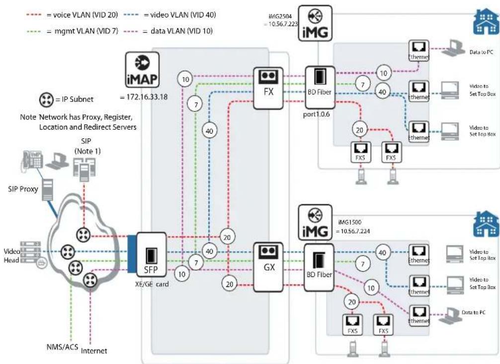
flowchart
graph TD
    A["iMG"] -->| = voice VLAN (VID 20) | B["FX"]
    A -->| = video VLAN (VID 40) | C["BD Fiber port1.0.6"]
    A -->| = mgmt VLAN (VID 7) | D["SFP"]
    A -->| = data VLAN (VID 10) | E["GX"]
    B --> F["FX"]
    C --> G["BD Fiber"]
    D --> H["DX"]
    E --> I["FXS"]
    F --> J["iMG1500 = 10.56.7.224"]
    G --> K["iMG1500 = 10.56.7.224"]
    H --> L["iMG1500 = 10.56.7.224"]
    I --> M["iMG1500 = 10.56.7.224"]
    N["iMAP"] -->| = voice VLAN (VID 20) | O["FX"]
    N -->| = video VLAN (VID 40) | P["BD Fiber port1.0.6"]
    N -->| = mgmt VLAN (VID 7) | Q["SFP"]
    N -->| = data VLAN (VID 10) | R["GX"]
    O --> S["iMG2504 = 10.56.7.223"]
    P --> T["iMG2504 = 10.56.7.223"]
    Q --> U["iMG2504 = 10.56.7.223"]
    V["SIP Proxy"] --> W["Video Head"]
    X["NMS/ACS"] --> Y["Internet"]
    Z["Note Network has Proxy, Register, Location and Redirect Servers"] --> AA["SIP (Note 1)"]
    AB["Data to PC"] --> AC["iMG1500 = 10.56.7.224"]
FIGURE 3-1 Sample Configuration - VLANs and Interfaces
awplus> enable
awplus# configure
awplus(config)# vlan database
<cr>
awplus(config)# vlan database
awplus(config-vlan)# vlan 7
awplus(config-vlan)# vlan 10
awplus(config-vlan)# vlan 40
awplus(config-vlan)# exit
awplus(config)# interface port1.0.1-port1.0.5
awplus(config-if)# switchport mode access
awplus(config-if)# exit
awplus(config)# interface port1.0.1
awplus(config-if)# switchport access vlan 10
awplus(config-if)# exit
awplus(config)# interface port1.0.2-port1.0.3
awplus(config-if)# switchport access vlan 40
awplus(config-if)# exit

---- On the iMG1500 (WAN port) ----
awplus(config)# interface port1.0.6
awplus(config-if)# switchport mode trunk
awplus(config-if)# switchport trunk allowed vlan add 7,10,40
Switching VLAN - iMG
awplus(config)# do show vlan
VLAN ID Name Type State Member ports
(u)-Untagged, (t)-Tagged ====================
1 Default STATIC ACTIVE port1.0.4(u) port1.0.5(u)
port1.0.6(u)
7 VLAN0007 STATIC ACTIVE port1.0.6(t)
10 VLAN0010 STATIC ACTIVE port1.0.1(u) port1.0.6(t)
40 VLAN0040 STATIC ACTIVE port1.0.2(u) port1.0.3(u)
port1.0.6(t)

---- On the iMG2500 (WAN port) ---- awplus(config)# interface port1.0.5 awplus(config-if)# switchport mode trunk
awplus(config-if)# switchport trunk allowed vlan add 7,10,40
awplus(config)# do show vlan
VLAN ID Name Type State Member ports
(u)-Untagged, (t)-Tagged ====================
1 Default STATIC ACTIVE port1.0.4(u) port1.0.5(u)
port1.0.6(u)
7 VLAN0007 STATIC ACTIVE port1.0.5(t)
10 VLAN0010 STATIC ACTIVE port1.0.1(u) port1.0.5(t)
40 VLAN0040 STATIC ACTIVE port1.0.2(u) port1.0.3(u)
port1.0.5(t)

awplus(config)# interface vlan7
awplus(config-if)# ip address dhcp
awplus(config-if)# exit
awplus(config)# interface vlan40
awplus(config-if)# ip address dhcp
awplus(config-if)# exit
awplus(config)# do show ip interface
Interface IP-Address Status Protocol
vlan1 172.0.0.103/16 admin up running
vlan7 10.0.0.251/16 admin up running
vlan10 unassigned admin up running
vlan40 10.1.0.254/16 admin up running

awplus(config)# interface vlan40
awplus(config-if)# ip igmp snooping
awplus(config-if)#
3.3.1 VLAN Commands
This subsection provides an alphabetical reference for commands used to configure the Forwarding Database (FDB)..
Table 3-3: VLAN Commands
| Commands |
| show vlan |
| switchport access vlan |
| switchport mode access |
| switchport mode trunk |
| switchport trunk allowed vlan |
| switchport trunk native vlan |
| switchport vlan-stacking (double tagging) |
| vlan |
| vlan database |
SHOW VLAN
Syntax
show vlan
Description This command displays information about all the VLANs configured.
Feature VLAN Commands
Mode Privileged Exec Mode
Release 4.1
Options NA
Note Wireless output only present on wireless-equipped models
Example To display information about VLAN 2, use the command:
awplus# show vlan 2
| VLAN ID | Name | Type | State | Member ports(u)-Untagged, (t)-Tagged |
| 2 | VLAN0002 | STATIC | ACTIVE | port1.0.5(u) port1.0.6(u) port1.0.7(u) port1.0.8(u) port1.0.7(u) dot11radio1.0.1(u) |
SWITCHPORT ACCESS VLAN
Syntax
switchport access vlan
Description This command changes the port-based VLAN of the current port.
Use the no variant of this command to change the port-based VLAN of this port to the default VLAN, vlan1.
Any untagged frame received on this port will be associated with the specified VLAN.
Feature VLAN Commands
Mode Interface Configuration
Release 4.1
Options
| Option Description Range | Default Value | ||
| <1-4094> The port-based VLAN ID for the port. | NA | NA | |
Note NA
Example To change the port-based VLAN to VLAN 3 for port1.0.2, use the commands:
awplus# (config)# interface port1.0.2
awplus# (config-if)# switchport access vlan 3
Example To reset the port-based VLAN to the default VLAN 1 for port1.0.2, use the commands:
awplus# (config)# interface port1.0.2
awplus# (config-if)# no switchport access vlan
SWITCHPORT MODE ACCESS
Syntax
switchport mode access
Description
This command sets the switching characteristics of the port to access mode. Received frames are classified based on the VLAN characteristics, then accepted or discarded based on the specified filtering criteria.
By default, ports are in access mode with ingress filtering on.
Use access mode to send untagged frames only.
Feature VLAN Commands
Mode Interface Configuration
Release 4.1
Options NA
Note NA
Example To set the access, mode use the following commands:
awplus# (config)# interface port1.0.2
awplus# (config-if)# switchport mode access
SWITCHPORT MODE TRUNK
| Syntax | switchport mode trunkshow interface switchport |
| Description | This command sets the switching characteristics of the port to trunk. Received frames are classified based on the VLAN characteristics.By default, ports are in access mode, are untagged members of the default VLAN (vlan1), and have ingress filtering on.A port in trunk mode can be a tagged member of multiple VLANs, and an untagged member of one native VLAN. |
Feature VLAN Commands
Mode Interface Configuration
Release 4.1
Options NA
Note To configure which VLANs this port will trunk for, use the switchport trunk allowed vlan command
Example
awplus# (config)# interface port1.1.3
awplus# (config-if)# switchport mode trunk
SWITCHPORT TRUNK ALLOWED VLAN
Syntax
switchport trunk allowed vlan none
switchport trunk allowed vlan add
Description
This command adds VLANs to be trunked over this switch port. Traffic for these VLANs can be sent and received on the port.
The all parameter sets the port to be a tagged member of all the VLANs configured on the device. The none parameter removes all VLANs from the port's tagged member set. The add and remove parameters will add and remove VLANs to and from the port's member set.
Use the no variant of this command to reset switching characteristics of a specified interface to negate a trunked configuration specified with switchport trunk allowed vlan command.
By default, ports are untagged members of the default VLAN (vlan1).
Feature VLAN Commands
Mode Interface Configuration
Release 4.2.3
Options
| Option Description Range | Default Value | ||
| none Allow no | VLANs to transmit and receive through the port. | NA NA | |
| add Add a VLAN | to transmit and receive through the port. NA NA | ||
| remove Remove | a VLAN from transmit and receive through the port. | NA NA | |
| <2-4094> The ID of the VLAN or VLANs that will be added to, or removed from, the port. A single VLAN, VLAN range, or comma-separated VLAN list can be set.For a VLAN range, specify two VLAN numbers: lowest, then highest number in the range, separated by a hyphen.For a VLAN list, specify the VLAN numbers separated by commas.Do not enter spaces between hyphens or commas when setting parameters for VLAN ranges or lists. | NA | 1 | |
Note NA
Example The following shows adding a single VLAN to the port's member set.
awplus# (config)# interface port1.0.2 awplus# (config-if)# switchport trunk allowed vlan add 2
Example The following shows adding a range of VLANs to the port's member set.
awplus# (config)# interface port1.0.2 awplus# (config-if)# switchport trunk allowed vlan add 2-4
Example The following shows adding a list of VLANs to the port's member set.
Switching VLAN - iMG
awplus# (config)# interface port1.0.2 awplus# (config-if)# switchport trunk allowed vlan add 2,3,4
SWITCHPORT TRUNK NATIVE VLAN
Syntax
switchport trunk native vlan {
no switchport trunk native vlan
Description
This command configures the native VLAN for this port. The native VLAN is used for classifying the incoming untagged packets.
Use the no variant of this command to revert the native VLAN to the default VLAN ID 1. Command negation removes tagged VLANs, and sets the native VLAN to the default VLAN.
Feature VLAN Commands
Mode Interface Configuration
Release 4.1
Options
| Option Description Range | Default Value | ||
| The ID of the VLAN that will be used to classify the incoming untagged packets. The VLAN ID must be a part of the VLAN member set of the port. | NA NA | ||
| none No native | VLAN specified. This option removes the native VLAN from the port and sets the acceptable frame types to vlan-tagged only.Note: Use the no variant of this command to revert to the default VLAN I as the native VLAN for the specified interface switchport - not none. | NA NA | |
Note NA
Example The following commands show configuration of VLAN 2 as the native VLAN for interface port1.0.2:
awplus# (config)# interface port1.0.2
awplus# (config-if)# switchport trunk native vlan 2
Example The following commands show the removal of the native VLAN for interface port1.0.2:
awplus# (config)# interface port1.0.2
awplus# (config-if)# switchport trunk native vlan none
Example The following commands revert the native VLAN to the default VLAN 1 for interface port 1.0.2:
awplus# (config)# interface port1.0.2
awplus# (config-if)# no switchport trunk native vlan
SWITCHPORT VLAN-STACKING (DOUBLE TAGGING)
Syntax
switchport vlan-stacking provider-port no switchport vlan-stacking
Description
This command enables VLAN stacking on a port and set it to be the provider-port. This is sometimes referred to as VLAN double-tagging, nested VLANs, or QinQ.
Use no parameter with this command to disable double tagging on an interface.
By default, ports are not VLAN stacking ports.
Traffic with two vlan tags can only be bridged, from the service provider to customer ports. All traffic that terminates on the device, whether being routed, used for management, etc. can have only one tag.
Feature VLAN Commands
Mode Interface Configuration
Release 4.1.2
Options
| Option Description Range | Default Value | |
| provider-port Set the port to be a provider port. This port must already be in trunk mode. | NA NA |
Note
Usually the WAN port is the provider port, since it interfaces the service provider's network. However, other ports (LAN) can be configured to be a Provider port, such as when daisy-chaining with another device. (The traffic still goes upstream to the Provider's network.)
Example To enable VLAN stacking, enter the following commands:
awplus# (config)# interface port1.0.2
awplus# (config-if)# switchport vlan-stacking provider-port
VLAN
Syntax vlan
Description This command creates VLANs, assigns names to them, and enables or disables them. The no variant of this command destroys the specified VLANs. By default, VLANs are enabled when they are created, and are always enabled.
Feature VLAN Commands
Mode VLAN Configuration
Release 4.1
Options
| Option Description Range | Default Value | ||
| The VID of the VLAN that will be enabled or disabled <2-4094>. | NA NA | ||
| The ASCII name of the VLAN. Maximum length: 32 characters. | NA NA | ||
| Specifies a range of VLAN identifiers. | NA | NA | |
Note NA
Example To create a VLAN, enter the following commands:
awplus# (config)# vlan database awplus# (config-if)# vlan 45 name accounts
VLAN DATABASE
Syntax
vlan database
Description This command enters the VLAN Configuration mode.
This command enters the VLAN configuration mode. You can then add or delete a VLAN, or modify its values.
Feature VLAN Commands
Mode Global Configuration Mode
Release 4.1
Options NA
Note NA
Example In the following example, note the change to VLAN configuration mode from Configure mode:
awplus# (config)# vlan database awplus# (config-vlan)#
3.4 PPPoE
3.4.1 PPPoE Protocol Components
PPPoE has two distinct stages, Discovery and Session, as described below.
When a Host wishes to initiate a PPPoE session, it must first perform Discovery to identify the Ethernet MAC address of the peer and establish a PPPoE SESSION_ID. While PPP defines a peer-to-peer relationship, Discovery is inherently a client-server relationship. In the Discovery process, a Host (the client) discovers an Access Concentrator (the server). Based on the network topology, there may be more than one Access Concentrator that the Host can communicate with. The Discovery stage allows the Host to discover all Access Concentrators and then select one. When Discovery completes successfully, both the Host and the selected Access Concentrator have the information they will use to build their point-to-point connection over Ethernet.
There are four steps in the Discovery stage. When complete, both peers know the PPPoE Session ID and the peer's Ethernet Address - These together are what uniquely define each PPPoE session. The four packet types are described below, as well as the fifth packet type (Terminate).
Table 3-4: PPPoE Packet Type Sequence for Discovery (and Termination)
| Packet Type^a | Sender Description |
| PADI (Initiation) host A broadcast packet that to discover the Access Concentrator. It includes the type of service the host is trying to get access to. | |
| PADO (Offer) Access Concentrator (AC) | The AC offers its MAC address if it can offer the type of service the host has asked for. One or more ACs may send this packet. The PADO packet is sent to the Unicast address of the PPPoE client. |
Table 3-4: PPPoE Packet Type Sequence for Discovery (and Termination)
| Packet Typea | Sender Description | |
| PADR (Request) host Confirms the | choice of the AC for this type of service. This packet is sent to the Unicast address of the Access Concentrator. The client may receive multiple PADO packets, but the client responds to the first valid PADO that the client received. If the initial PADI packet had a blank "service-name" field filed, the client populates the "service-name" field of the PADR packet with the first service name that had been returned in the PADO packet. | |
| PADS (Session Confirmation) | AC When the PADR is received, the Access Concentrator generates unique session identification (ID) for the Point-to-Point Protocol (PPP) session and returns this ID to the PPPoE client in the PADS packet. This packet is sent to the Unicast address of the client.When this process has completed, the client is aware of the address of the Access Concentrator and a session ID has been established. At this point, a normal PPP session begins. | |
| PADI (Terminate) host or AC Optional packet to terminate the PPPoE session. The session ID is discarded, and the host must begin the Discovery process again. | ||
a. PAD for all packet types = PPPoE Active Discovery. Word in parentheses is for final letter in acronym)
Once the session begins, the PPP data is sent as in any other PPP encapsulation, with all Ethernet packets Unicast. Note that the session_ID must be the value assigned during Discovery, and it must not change during the session. When the LCP terminates, the host and access concentrator must stop using that PPPoE session, and the discovery process begins again.
3.4.2 Automatically populating routing table and DNS server table
During the PPP connection establishment, the Network Control Protocol called PPP Internet Protocol Control Protocol (IPCP) is called to negotiate the IP address of the local end of the link and to retrieve the Default Route and a list of DNS server ip addresses.
The negotiated local IP address is used to assign the IP address to the VLAN interface. In this case when the PPP session is established, the VLAN interface changes from having a null IP address to the new negotiated IP address and every time the PPP session is closed, the IP interface will revert back to having a null IP address.
The PPPoE connection has the capability to set the CPE's default route. To enable setting the CPE's default route use the following command in VLAN interface sub-mode:
ppp ipcp default route
Use the no version of this command to prevent PPP from setting the default route.
Note: If more than one PPPoE connection is configured to support setting the default route and multiple PPPoE connections receive a default route from server, the setting of the default route will be determined by the order of the PPPoE link establishment.
The PPPoE transport object is also able to set automatically the primary and secondary DNS servers. Use the following command to enable setting of Primary and Secondary DNS servers:
ppp ipcp dns request
Use the no version of this command to prevent PPP from setting the DNS servers.
Note: If more than one PPPoE connection is configured to support setting the DNS server and multiple PPPoE connections receive a DNS server from server - the setting of the DNS server will be indeterminate depending on order of the PPPoE link establishment.
3.4.3 Activating the Feature
The system is designed to implement more than one embedded PPPoE clients to be able to connect to external Access Concentrators. One PPPoE client may be configured per VLAN; a PPPoE connection is configured on the VLAN interface.
The configuration of a PPPoE connection is as follows:
- Enter interface command submode for vlan:
interface vlan123
- Set authentication protocol:
ppp authentication pap OR
ppp authentication chap
- Set the username/password:
ppp sent-username <username> password <password>
- Enable pppoe on vlan interface:
pppoe enable
- Disable pppoe on vlan interface:
no pppoe enable
3.4.4 PPPoE Commands
This subsection provides an alphabetical reference for commands used to configure PPPoE.
Table 3-5: PPPoE Commands
| Commands |
| ppp authentication |
| ppp ipcp default route |
| ppp ipcp dns request |
| ppp sent-username |
| pppoe enable |
PPP AUTHENTICATION
Syntax
ppp authentication {chap | pap | auto}
Description
This command sets the authentication method as either:
Password Authentication Protocol (PAP) - provides a simple method for a remote node to establish its identity using a two-way handshake. After the PPP link establishment phase is complete, a username and password pair is repeatedly sent by the remote node across the link (in clear text) until authentication is acknowledged, or until the connection is terminated. PAP is not a secure authentication protocol. Passwords are sent across the link in clear text and there is no protection from playback or trail-and-error attacks. The remote node is in control of the frequency and timing of the login attempts
CHAP - The Challenge Handshake Authentication Protocol (CHAP) verifies the identity of the peer by means of a three-way handshake. The connection is verified by comparing calculated values. Otherwise the connection is dropped.
Feature PPP
Mode VLAN Configuration Mode
Release 4.1.2
Options
| Option Description | Range | Default Value | |
| chap Challenge | Handshake Authentication Protocol; the server sends an authentication request to the remote user dialing in. PAP passes the encrypted username and password and identifies the remote end | NA NA | |
| pap | Password Authentication Protocol; the server sends and authentication request to the remote user dialing in. PAP passes the unencrypted username and password and identifies the remote end. | NA NA | |
| auto | The authentication protocol used by the remote PPP server is discovered and used. | NA NA |
Note NA
Example In the following example, note the change to VLAN configuration mode from Configure mode:
awplus# (config)# interface vlan4
awplus# (config-if)# ppp authentication pap
PPP IPCP DEFAULT ROUTE
Syntax
ppp ipcp default route
no ppp ipcp default route
Description
This command is used to allow ppp to the CPE's default route. The no form of this command disallows the configuration of a default route via pppoe.
Feature PPP
Mode VLAN Configuration Mode
Release 4.1.2
Options NA
Note NA
Example In the following example,:
awplus# (config)# interface vlan4
awplus# (config-if)# ppp ipcp default route
PPP IPCP DNS REQUEST
Syntax
ppp ipcp dns request
no ppp ipcp dns request
Description
This command is used to allow the configuration of dns servers through PPP. The no form of this command to prevent PPP from setting the dns servers.
Feature PPP
Mode VLAN Configuration Mode
Release 4.1.2
Options NA
Note NA
Example Refer to the following example,
awplus# (config)# interface vlan4
awplus# (config-if)# ppp ipcp dns request
PPP SENT-USERNAME
Syntax ppp sent-username pppUsername=
Description This command sets the username and password. This command must be input so that the PPPoE connection can be completed.
Feature PPP
Mode VLAN Configuration Mode
Release 4.1.2
Options
| Option Description Range | Default Value | |
| pppUsername Sets the user name. Maximum length is 64 characters NA NA | ||
| password Sets the password. NA NA |
Note NA
Example In the following example, note the change to VLAN configuration mode from Configure mode:
awplus# (config)# interface vlan4
PPPOE ENABLE
Syntax pppoe enable no pppoe enable
Description This command enable the PPPoE feature and is the last command used to implement the PPPoE feature. The no form of this command disables the feature.
Feature PPP
Mode VLAN Configuration Mode
Release 4.1.2
Options NA
Note NA
Example In the following example,:
awplus# (config)# interface vlan4 awplus# (config-if)# pppoe enable
awplus# (config-if)# ppp sent-username user1 password jcplklkX
3.5 HPNA
Since multiple features include provisioning at the interface (and subinterface) level, multiple commands are affected as well. The following table lists these commands. The commands listed in HPNA Commands are specifically for the HPNA interface.
Table 3-6: Commands affected by the HPNA Interface
| Command Effect Notes | ||
| show vlan HPNA port can be included if using the iMG2524H | ||
| show vlan Output includes HPNA port | ||
| interface hpna1.0.1 Supports the following sub-commands-switchport mode access-switchport mode trunk-switchport access vlan-switchport trunk allowed vlan-switchport trunk native vlan | ||
| show mac address-table Can include interface hpna1.0.1 | ||
| clear mac address-table dynamic | Can include interface hpna1.0.1 | |
| clear mac address-table static | Can include interface hpna1.0.1 | |
3.5.1 HPNA Commands
This chapter provides an alphabetical reference of commands used to configure and display interfaces.
Table 3-7: HPNA Commands
| Commands |
| interface hpna1.0.1 |
| clear hpna counters |
| show hpna counters |
| show hpna stations |
| show test |
| test interface hpna1.0.1 |
INTERFACE HPNA1.0.1
Syntax interface hpna1.0.1
Description This command access the interface level for the HPNA interface. For release 4.2 the number is always 1.0.1, but will change when there is more than on HPNA port.
Feature Switching Commands
Mode Global Configuration Mode
Release 4.2
Options NA
Note NA
Example The following example shows the command to enable the hpna interface.
awplus(config)# interface hpna1.0.1
awplus(config-if-hpna)# no shutdown
CLEAR HPNA COUNTERS
Syntax clear hpna counters [
Description Use this command to clear statistic counters for hpna stations.
Description If the command is entered while there is a test running a warning message is returned.
Feature Switching Commands
Mode Global Configuration Mode
Release 4.2
Options
| Option Description Range | Default Value | ||
| MAC The MAC | address of the HPNA station where the statistics are cleared. | NA NA | |
Note The command returns an error message if the hpna interface is disabled.
Example The following example shows what is displayed
awplus(config)# interface hpna1.0.1
awplus(config-if-hpna)# do clear hpna counters
SHOW HPNA COUNTERS
Syntax
show hpna counters [
Description Use this command to clear statistic counters for hpna stations.
Feature Switching Commands
Mode Global Configuration Mode
Release 4.2
Options
| Option Description Range | Default Value | ||
| station MAC address | The MAC address of the HPNA station where the statistics are retrieved | NA NA | |
Note
The command returns an error message if the hpna interface is disabled.
Example The following example shows what is displayed
awplus(config)# interface hpna1.0.1
awplus(config-if-hpna)# do show hpna counters
awplus# show hpna counters
Counters for 00:0d:da:0d:97:55
Counter Value Description
| txPkt | 1177 | Total (good and bad) transmitted packets |
| txByte | 91026 | Total (good and bad) transmitted bytes |
| rxPkt | 1020 | Total (good and bad) received packets |
| rxByte | 73278 | Total (good and bad) received bytes |
| txBroadcast | 160 | Transmitted broadcast packets |
| rxBroadcast | 0 | Received broadcast packets |
| txMulticast | 0 | Transmitted multicast packets |
| rxMulticast | 0 | Received multicast packets |
| rxCrc | 1 | Packets received with CRC error(s) |
| rxHostCrc | 1 | Packets with CRC errors sent to the host |
| rxShort | 0 | Received short packets |
| txShort | 0 | Short packets received from the host |
| txDropped | 0 | Packets from host dropped due to lack of HPNA resources |
| rxDropped | 0 | Received packets dropped due to lack of HPNA resources |
| ctlReqPkt | 840 | Control requests from local host (CERT/stats/FW loading) |
| ctlReplPkt | 840 | Control replies to local host (CERT/stats/FW loading) |
| ctlRemoteReqPkt | 0 | Control requests from remote HPNA host (CERT/Mgmt/FW) |
| ctlRemoteReplPkt | 0 | Control replies to remote host (CERT/stats/FW loading) |
| txPercentPerCycle | 2.41 | % time HPNA transmitter is busy per HPNA time cycle |
| idlePercentPerCycle | 97.39 | % time HPNA media is idle per HPNA time cycle |
| txPercentAvg | 3.62 | % time HPNA transmitter is busy on average |
| idlePercentAvg | 95.04 | % time HPNA media is idle on average |
SHOW HPNA STATIONS
Syntax show hpna stations [MAC]
Description Use this command to display the HPNA stations connected to the HPNA interface. If the command is entered while there is a test still running a warning message is returned
Feature Switching Commands
Mode Global Configuration Mode
Release 4.2
Note
| Option Description Range | Default Value | ||
| MAC The MAC | address of the HPNA station NA NA | ||
Note The command cannot be executed if the hpna interface is disabled
Example The following example shows what is displayed
awplus(config)# interface hpna1.0.1
awplus(config-if-hpna)# do show hpna stations
Idx MAC Address Link Sync Master Firmware Version HW Profile
| 0 | 00:0d:da:0d:97:55 | Yes | Yes | Yes (local device) | CG3210H 1.9.4 | Coax 12-44 |
| 1 | 00:01:40:25:98:eb | Yes | Yes | No | CG3010H 1.9.4 | Coax 12-28 |
| 2 | 00:01:40:25:98:e6 | Yes | Yes | No | CG3010H 1.9.4 | Coax 12-28 |
| 3 | 00:01:40:25:98:d1 | Yes | Yes | No | CG3010H 1.9.4 | Coax 12-28 |
| 4 | 00:01:40:25:99:c5 | Yes | Yes | No | CG3010H 1.9.4 | Coax 12-28 |
| 5 | 00:01:40:25:98:c9 | Yes | Yes | No | CG3010H 1.9.4 | Coax 12-28 |
| 6 | 00:01:40:25:aa:34 | Yes | Yes | No | CG3010H 1.9.4 | Coax 12-28 |
SHOW TEST
Syntax
show test
Description
Use this command to display the latest CERT test results. If the command is entered while there is a test running a warning message is returned
Feature Switching Commands
Mode Global Configuration Mode
Release 4.2
Options NA
Note
The command returns an error message if the hpna interface is disabled
Example The following example shows what is displayed
awplus(config)# interface hpna1.0.1
awplus(config-if-hpna)# test interface hpna1.0.1
awplus(config-if-hpna)# do show test
MAC
Frames
| Source | Destination | Xmtd | Rcvd | % | SNR | Rate | Rx Power |
| 00:0d:da:0d:97:55 | 00:01:40:25:98:eb | 1000 | 1000 | 100.00 | 41.56 | 112 Mbps | -8.89 |
| 00:0d:da:0d:97:55 | 00:01:40:25:98:e6 | 1000 | 1000 | 100.00 | 40.93 | 112 Mbps | -9.08 |
| 00:0d:da:0d:97:55 | 00:01:40:25:98:c9 | 1000 | 1000 | 100.00 | 38.75 | 112 Mbps | -15.99 |
| 00:0d:da:0d:97:55 | 00:01:40:25:99:c5 | 1000 | 1000 | 100.00 | 39.37 | 112 Mbps | -9.14 |
| 00:0d:da:0d:97:55 | 00:01:40:25:98:d1 | 1000 | 1000 | 100.00 | 40.00 | 112 Mbps | -16.15 |
| 00:0d:da:0d:97:55 | 00:01:40:25:aa:34 | 1000 | 1000 | 100.00 | 39.37 | 112 Mbps | -13.02 |
| 00:01:40:25:98:eb | 00:0d:da:0d:97:55 | 1000 | 1000 | 100.00 | 41.25 | 128 Mbps | -7.20 |
| 00:01:40:25:98:eb | 00:01:40:25:98:e6 | 1000 | 1000 | 100.00 | 37.81 | 112 Mbps | -29.66 |
| 00:01:40:25:98:eb | 00:01:40:25:98:c9 | 1000 | 1000 | 100.00 | 37.81 | 112 Mbps | -36.75 |
| 00:01:40:25:98:eb | 00:01:40:25:99:c5 | 1000 | 1000 | 100.00 | 38.12 | 112 Mbps | -30.84 |
| 00:01:40:25:98:eb | 00:01:40:25:98:d1 | 1000 | 1000 | 100.00 | 36.56 | 96 Mbps | -37.11 |
| 00:01:40:25:98:eb | 00:01:40:25:aa:34 | 1000 | 1000 | 100.00 | 38.12 | 112 Mbps | -33.40 |
| 00:01:40:25:98:e6 | 00:0d:da:0d:97:55 | 1000 | 1000 | 100.00 | 41.25 | 128 Mbps | -7.35 |
| 00:01:40:25:98:e6 | 00:01:40:25:98:eb | 1000 | 1000 | 100.00 | 39.06 | 112 Mbps | -30.07 |
| 00:01:40:25:98:e6 | 00:01:40:25:98:c9 | 1000 | 1000 | 100.00 | 37.81 | 112 Mbps | -36.89 |
| 00:01:40:25:98:e6 | 00:01:40:25:99:c5 | 1000 | 1000 | 100.00 | 38.75 | 112 Mbps | -29.97 |
| 00:01:40:25:98:e6 | 00:01:40:25:98:d1 | 1000 | 1000 | 100.00 | 36.56 | 112 Mbps | -37.18 |
| 00:01:40:25:98:e6 | 00:01:40:25:aa:34 | 1000 | 1000 | 100.00 | 37.81 | 112 Mbps | -33.55 |
| 00:01:40:25:98:d1 | 00:0d:da:0d:97:55 | 1000 | 1000 | 100.00 | 41.56 | 128 Mbps | -14.12 |
| 00:01:40:25:98:d1 | 00:01:40:25:98:eb | 1000 | 1000 | 100.00 | 36.87 | 112 Mbps | -37.05 |
| 00:01:40:25:98:d1 | 00:01:40:25:98:e6 | 1000 | 1000 | 100.00 | 37.50 | 112 Mbps | -36.91 |
| 00:01:40:25:98:d1 | 00:01:40:25:98:c9 | 1000 | 1000 | 100.00 | 38.43 | 112 Mbps | -35.32 |
| 00:01:40:25:98:d1 | 00:01:40:25:99:c5 | 1000 | 1000 | 100.00 | 36.56 | 112 Mbps | -37.25 |
| 00:01:40:25:98:d1 | 00:01:40:25:aa:34 | 1000 | 1000 | 100.00 | 35.93 | 96 Mbps | -39.59 |
| 00:01:40:25:99:c5 | 00:0d:da:0d:97:55 | 1000 | 1000 | 100.00 | 41.25 | 128 Mbps | -7.34 |
| 00:01:40:25:99:c5 | 00:01:40:25:98:eb | 1000 | 1000 | 100.00 | 37.18 | 112 Mbps | -31.06 |
| 00:01:40:25:99:c5 | 00:01:40:25:98:e6 | 1000 | 1000 | 100.00 | 39.06 | 112 Mbps | -29.47 |
| 00:01:40:25:99:c5 | 00:01:40:25:98:c9 | 1000 | 1000 | 100.00 | 36.25 | 112 Mbps | -36.39 |
| 00:01:40:25:99:c5 | 00:01:40:25:98:d1 | 1000 | 1000 | 100.00 | 36.87 | 112 Mbps | -36.63 |
| 00:01:40:25:99:c5 | 00:01:40:25:aa:34 | 1000 | 1000 | 100.00 | 38.12 | 112 Mbps | -33.25 |
| 00:01:40:25:98:c9 | 00:0d:da:0d:97:55 | 1000 | 1000 | 100.00 | 41.56 | 128 Mbps | -14.14 |
| 00:01:40:25:98:c9 | 00:01:40:25:98:eb | 1000 | 1000 | 100.00 | 36.25 | 112 Mbps | -36.93 |
| 00:01:40:25:98:c9 | 00:01:40:25:98:e6 | 1000 | 1000 | 100.00 | 35.93 | 112 Mbps | -36.79 |
| 00:01:40:25:98:c9 | 00:01:40:25:99:c5 | 1000 | 1000 | 100.00 | 37.50 | 112 Mbps | -36.74 |
| 00:01:40:25:98:c9 | 00:01:40:25:98:d1 | 1000 | 1000 | 100.00 | 37.50 | 112 Mbps | -35.33 |
Switching HPNA
| 00:01:40:25:98:c9 | 00:01:40:25:aa:34 | 1000 | 1000 | 100.00 | 35.93 | 112 | Mbps | -39.41 |
| 00:01:40:25:aa:34 | 00:0d:da:0d:97:55 | 1000 | 1000 | 100.00 | 41.56 | 128 | Mbps | -10.70 |
| 00:01:40:25:aa:34 | 00:01:40:25:98:eb | 1000 | 1000 | 100.00 | 37.81 | 112 | Mbps | -33.50 |
| 00:01:40:25:aa:34 | 00:01:40:25:98:e6 | 1000 | 1000 | 100.00 | 37.18 | 112 | Mbps | -33.09 |
| 00:01:40:25:aa:34 | 00:01:40:25:98:c9 | 1000 | 1000 | 100.00 | 35.31 | 96 | Mbps | -39.33 |
| 00:01:40:25:aa:34 | 00:01:40:25:99:c5 | 1000 | 1000 | 100.00 | 37.18 | 112 | Mbps | -33.15 |
| 00:01:40:25:aa:34 | 00:01:40:25:98:d1 | 1000 | 1000 | 100.00 | 34.68 | 96 | Mbps | -39.59 |
TEST INTERFACE HPNA1.0.1
Syntax test interface hpna1.0.1 [to [MAC]] [frames
Description Use this command to start CERT tests on HPNA interface. CLI prompt is immediately returned after the command is entered even if CERT tests are not terminated yet. To display the CERT tests results use the command show test cert.
Feature Switching Commands
Mode Global Configuration Mode
Release 4.2
Options
| Option Description Range | Default Value | ||
| to MAC The MAC address of the HPNA station NA NA | |||
| frames | The number of frames to use during the HPNA CERT | 1-99999 | NA |
Note The command cannot be executed if the hpna interface is disabled.
Example The following example shows what is displayed
awplus(config)# interface hpna1.0.1
awplus(config-if-hpna)# test interface hpna1.0.1
HPNA CERT test started
3.6 Wireless
Table 2-8 below lists existing commands that are affected by the inclusion of wireless, while table 2-9 documents new commands added specifically for wireless.
Table 3-8: Commands affected by the Wireless Interface
| Command | Effect | Notes |
| interface port | Supports additional ‘dot11radio1.0.1’ sub-mode & associated commands as described in table 2-9 below | |
| show interface | Supports additional ‘dot11radio1.0.1 [status]’ sub-commands as described in table 2-9 below. The following sub-commands also include wireless interface information:- show interface brief- show interface status- show interface switchport | |
| show ip igmp groups | The wireless interface is now included when appropriate on wireless-equipped models | |
| show mac address-table | Wireless subsystem software version information is displayed if using a wireless-equipped model | |
| show version | Wireless subsystem software version information is displayed if using a wireless-equipped model |
Table 3-8: Commands affected by the Wireless Interface
| Command Effect Notes | ||
| show vlan | Wireless ports are included if using a wireless-equipped model |
3.6.1 Wireless Commands
This chapter provides an alphabetical reference of commands used to configure and display interfaces.
Table 3-9: Wireless Commands
| Commands |
| authentication key-management |
| authentication open |
| channel |
| client-isolation |
| config-reset |
| deny |
| dot11 ssid |
| guest-mode |
| interface dot11radio1.0.1 |
| max-association |
| permit |
| protocol-family |
| show controllers dot11 radio |
| show dot11 associations |
| show controllers dot11 radio |
| show dot11 bssid |
| show interface dot11radio1.0.1 |
| show interface dot11radio1.0.1 status |
| show wireless country supported |
| shutdown |
| ssid-name |
| vlan |
| world-mode dot11d country-code |
| wpa-psk |
AUTHENTICATION KEY-MANAGEMENT
Syntax
authentication key-management {wpa-mixed-psk | wpa-psk | wpa2-psk}
Description
Use this command to configure the key management for the radio interface. The WiFi interface supports WiFi Protected Access (WPA) Pre-Shared Key, WPA2 and WPA/WP2 Mixed Mode where:
- wpa-mixed-psk: Employs the WPA/TKIP and WPA2/CCMP-AES encryption protocol
- wpa-psk: Employs the TKIP encryption protocol
- wpa2-psk: Employs the CCMP-AES encryption protocol
Feature Switching Commands
Mode Global SSID Configuration Mode
Release 4.3.3
Note
Configure the key with command 'wpa-psk {hex | ascii}
Options
| Option Description | Range | Default Value | |
| key-management Type of authentication required for the selected network SSID. Possible values are: wpa-mixed-psk wpa-psk wpa2-psk | NA NA | ||
Example An example can be the following:
awplus(config)# dot11 ssid iMG1425W_30_01_02
awplus(config-if-ssid)# authentication key-management wpa-mixed-psk
AUTHENTICATION OPEN
Syntax
authentication open
Description
Use this command to configure the radio interface for open authentication.
Use the 'no' form to restore the default value.
Feature Switching Commands
Mode Global SSID Configuration Mode
Release 4.3.3
Options
| Option Description Range | Default Value | ||
| authentication open | Configure the radio interface, for specified SSID to support open authentication. | NA NA | |
Example
awplus(config)# dot11 ssid iMG1425W_30_01_02
awplus(config-if-ssid)# authentication open
CHANNEL
Syntax channel {channel number
Description Use this command to set the radio channel frequency, radio channel number or automatic channel selection (least-congested). Use the 'no' form to restore the default channel.
Feature Switching Commands
Mode dot1radio ConfigurationMode
Release 4.3.3
Options
| Option Description | Range Default Value | ||
| The channel number selected for the Wi-Fi interface. Possible values are between 1 and 13 depending on the country. | NA NA | ||
| The frequency (expressed in MHz) corresponding to the channel. The possible values are:Channel 1 - 2412 MHzChannel 2 - 2417 MHzChannel 3 - 2422 MHzChannel 4 - 2427 MHzChannel 5 - 2432 MHzChannel 6 - 2437 MHzChannel 7 - 2422 MHzChannel 8 - 2447 MHzChannel 9 - 2452 MHzChannel 10 - 2457 MHzChannel 11 - 2462 MHzChannel 12 - 2467 MHzChannel 13 - 2472 MHz | NA NA | ||
| Auto-channel. | NA NA |
Example The following examples show how to set the channel:
Example 1 set channel number:
awplus(config)# interface dotllradiol.0.1
awplus(config-if-dotllradio)# channel 3
awplus(config-if-dotllradio)# end
Example 2 set channel frequency in MHz:
awplus(config)# interface dot11radio1.0.1
awplus(config-if-dot11radio)# channel 2422
awplus(config-if-dot11radio)# end
Example 3 set auto channel:
awplus(config)# interface dot11radio1.0.1
awplus(config-if-dot11radio)# least-congested
CLIENT-ISOLATION
Syntax
client-isolation
Description
Use this command to enable client isolation. Use the 'no' form to disable client isolation. When client isolation is enabled, the broadcast traffic generated by one wireless host does not interfere with the traffic of the other wireless hosts.
Feature Switching Commands
Mode Global Configuration Mode
Release 4.3.3
Note Use '[do] show interface dot1radio1.0.1' for display this information.
Options
| Option Description Range | Default Value | |
| client-isolation Configure the radio interface (for the specified SSID) to support wireless client isolation. | NA NA |
Example The following example enables client isolation on a specific Wi-Fi network
awplus(config)# dot11 ssid iMG1425W_30_01_02
awplus(config-if-ssid)# client-isolation
CONFIG-RESET
Syntax awplus(config-if-dot11radio)# config-reset
Syntax
Description Use this command to reset the wireless configuration to default values.
Feature Switching Commands
Mode dot11radio ConfigurationMode
Release 4.3.3
Note The 'no' form is not present for this command
Options
| Option Description Range | Default Value | |
| config-reset Reset the wireless module to factory. NA NA |
Example The following example resets the wireless interface to the default settings
awplus(config)# interface dotllradiol.0.1
awplus(config-if-dotllradio)# config-reset
Switching Wireless
DENY
Syntax
deny [
Description Use the command "deny" followed by a mac-address to create a black list of mac addresses that are not allowed to connect. Use the command "deny" without any option to enable the black list.
Feature Switching Commands
Mode Global SSID Configuration Mode
Release 4.3.3
Note It is important at first to set a list of mac-addresses for blacklist and enable this list afterwards. If the list is empty the following message will be shown in your console:
% The filter list must contain at least one entry before filtering can be enabled.
Note: You can not activate two lists (white and black) at the same time.
Options
| Option Description Range | Default Value | |
| mac-address The mac addresses to be added to the black list. NA NA |
Example The following example adds three wireless hosts to the black list and enables the black list
awplus(config)# dot11 ssid iMG1425W_30_01_02
awplus(config-if-ssid)# deny 00:01:02:03:04:05
awplus(config-if-ssid)# deny 00:01:02:03:04:06
awplus(config-if-ssid)# deny 00:01:02:03:04:07
awplus(config-if-ssid)# deny
DOT11 SSID
Syntax
dot11 ssid
Description Use this command to enter SSID configuration mode for the named SSID.
Feature Switching Commands
Mode Global Configuration Mode
Release 4.3
Options
| Option Description Range | Default Value | |
| ssid-name Name of the existing SSID that you wish to configure. NA NA |
Example The following example shows the wireless interface network SSIDs.
awplus# show dot11 bssid
Interface BSSID Guest SSID VLAN
dot11radio1.0.1 e2:0c:25:00:01:6d Yes iMG1425W_00_01_6d Default
dot11radio1.0.1 Guest1
dot11radio1.0.1 Guest2
dot11radio1.0.1 Guest3
awplus# configure
Enter configuration commands, one per line. End with CNTL/Z.
awplus(config)# dot11 ssid iMG1425W_00_01_6d
awplus(config-if-ssid)#
GUEST-MODE
Syntax guest-mode
Description This command hides or makes visible the network SSID to wireless hosts. The [no] format hides the network SSID.
Feature Switching Commands
Mode Global SSID Configuration Mode
Release 4.3.3
Note Use '[do] show dot11 bssid' to display this information
Options
| Option Description Range | Default Value | |
| guest-mode Make visible the network SSID. NA NA |
Example The following example shows how to make visible or hide the network SSID.
awplus(config)# dot11 ssid iMG1425W_30_01_02
awplus(config-if-ssid)# guest-mode
hide access point use 'no' form, an example is:
awplus(config)# dot11 ssid iMG1425W_30_01_02
awplus(config-if-ssid)# no guest-mode
INTERFACE DOT11RADIO1.0.1
Syntax interface dot11radio1.0.1
Description This command access the interface level for the 2.4GHz wireless.
Feature Switching Commands
Mode Global Configuration Mode
Release 4.2
Options NA
Note NA
Example The following example shows the command to software-enable the wireless interface
awplus(config)# interface dot11radio1.0.1
awplus(config-if-dot11radio)# no shutdown
MAX-ASSOCIATION
Syntax
max-associations
[no] max-associations
Description
Use this command to specify the maximum number of wireless hosts that can connect to the wireless network.
Feature Switching Commands
Mode Global Configuration Mode
Release 4.3.3
Options
| Option Description Range | Default Value | |
| max-associations Configure the maximum number of hosts (for the specified SSID) supported by the radio interface. | 1-5|2 32 |
Example The following example sets at 512, the maximum number of Wi-Fi stations supported by the selected network SSID.
awplus(config)# dot11 ssid iMG1425W_30_01_02
awplus(config-if-ssid)# max-associations 512
Restore max association with 'no' form an example is:
awplus(config)# dot11 ssid iMG1425W_30_01_02
awplus(config-if-ssid)# no max-associations
Switching Wireless
PERMIT
Syntax permit [
Description Use the command "permit" followed by a mac address to create a white list of mac addresses allowed to connect. Use the command "permit" without any option to enable the white list.
Feature Switching Commands
Mode Global SSID Configuration Mode
Release 4.3.3
Note It is important at first to set a list of mac-addresses for white list and enable this list afterwards. If the list is empty the following message will be shown in your console:
% The filter list must contain at least one entry before filtering can be enabled.
Note: You can not activate two lists (white and black) at the same time.
Note: Use "[do] show dot11 associations" for display this setting.
Options
| Option Description Range | Default Value | |
| mac-address The mac address to be added to the white list. NA NA |
Example The following example adds three wireless hosts to the white list and enables the white list.
awplus(config)# dot11 ssid iMG1425W_30_01_02
awplus(config-if-ssid)# permit 00:01:02:03:04:05
awplus(config-if-ssid)# permit 00:01:02:03:04:06
awplus(config-if-ssid)# permit 00:01:02:03:04:07
awplus(config-if-ssid)# permit
PROTOCOL-FAMILY
Syntax protocol-family
Description Use this command to select the Wi-Fi mode. Possible modes are: b, g, g-only, n, n-only Use the [no] form to restore the default mode to "n".
Options dot | radio ConfigurationMode
Mode Global Configuration Mode
Release 4.3.3
Options
| Option Description Range | Default Value | |
| Wi-Fi mode The Wi-Fi mode. Some of the possible values: b, g, g-only, n, n-only. | NA | n |
Example The following example shows how to force wireless interface to operate in "b" mode.
awplus(config)# interface dot11radio1.0.1 awplus(config-if-dot11radio)# protocol-family b
Description Displays the radio type, frequency and current channel.
Feature Switching Commands
Mode Global Configuration Mode
Release 4.3.3
Options
| Option Description | Range | Default Value | |
| show controllers dot11radio | Display the radio type, frequency and current channel. | NA NA |
Example The following example shows the configuration of the wireless interface.
awplus# show controllers dot11radio1.0.1
Interface dot11radio1.0.1
Radio ATHEROS AR5B97, Driver Version 0.9.17.1, Hostapd Version v1.0
Wireless multifunction button status: Enabled
Country: UNITED STATES (US)
Current Frequency: 2412 Mhz is Channel 1 in auto select
Allowed Frequencies: 2412(1) 2417(2) 2422(3) 2427(4) 2432(5) 2437(6) 2442(7) 2447(8)
Current IEEE 802.11 protocol family: n
Allowed IEEE 802.11 protocols family: b g g-only n n-only
SHOW DOT 11 ASSOCIATIONS
Syntax
awplus# show dot11 associations
Description
Display the radio association table, radio association statistics, encryption mode.
Feature Switching Commands
Mode Global Configuration Mode
Release 4.3.3
Options
| Option Description Range | Default Value | ||
| show dot11 associations | Display the radio association table. NA NA | ||
Example The following example shows the wireless hosts associated to each network SSID.
awplus# show dot11 associations
802.11 Client Stations on dot11radio1.0.1 SSID1
IEEE 802.11n SSID: iMG1425W_30_01_02
MAC Filtering State: Permitted
Denied Mac Addresses
00:01:02:03:04:05
00:01:02:03:04:06
Permitted Mac Addresses
00:03:06:06:09:12
SHOW DOT11 BSSID
Syntax show dot11 bssid
Description Use the show dot11 bssid command to display the relationship between SSIDs and BSSIDs or MAC addresses.
Feature Switching Commands
Mode Global Configuration Mode
Release 4.3
Example The following example shows the networks SSIDs and the associated BSSID and VLAN.
awplus# show dotll bssid
| Interface | BSSID | Guest | SSID | VLAN |
| dot11radio1.0.1 | e2:0c:25:00:01:71 | Yes | iMG1425W_00_01_71 | 2 |
| dot11radio1.0.1 | f2:0c:25:00:01:71 | Yes | Guest1 | 2 |
| dot11radio1.0.1 | 02:0c:25:00:01:71 | Yes | Guest2 | 2 |
| dot11radio1.0.1 | 12:0c:25:00:01:71 | Yes | Guest3 | 2 |
SHOW INTERFACE DOT11RADIO1.0.1
Syntax show interface dot11radio1.0.1
Description Use this command to display the wireless interface configuration and status.
Feature Switching Commands
Mode Global Configuration Mode
Release 4.3
Options NA
Example The following example if wireless interface is enabled.
awplus# show interface dot11radio1.0.1
Interface dot11radio1.0.1
Link is UP, administrative state is UP ethW1s1:
MAC address is e2:0c:25:00:01:6d
IEEE 802.11ng ESSID:"iMG1425W_00_01_6d"
Mode:Master Frequency:2.437 GHz Access Point: E2:0C:25:00:01:6D
Bit Rate:144.4 Mb/s Tx-Power:19 dBm
RTS thr:off Fragment thr:off
Encryption key:off
Power Management: off
Link Quality=94/94 Signal level=-96 dBm Noise level=-95 dBm
Rx invalid nwid:3600 Rx invalid crypt:0 Rx invalid frag:0
Tx excessive retries:0 Invalid misc:0 Missed beacon:0
Current channel is 6
SHOW INTERFACE DOT11RADIO1.0.1 STATUS
Syntax
show interface dot11radio1.0.1 status
Description
Use this command to display the status of the wireless interface.
Feature Switching Commands
Mode Global Configuration Mode
Release 4.3
Example The following example shows what is displayed.
awplus# show interface dotllradiol.0.1 status
Port
Name
Status
Vlan Duplex
Speed Type
dot11radio1.0.1
up
1 auto
auto N/A
awplus#
SHOW WIRELESS COUNTRY SUPPORTED
Syntax show country supported
Description Use this command to display the name of the supported countries and their abbreviations.
Feature Switching Commands
Mode Global Configuration Mode
Release 4.3.2
Example The following example shows what is displayed.
awplus# show wireless country
Interface dot11radio1.0.1
| ISO Country Code | Country Name |
| 'AL' | 'ALBANIA' |
| 'DZ' | 'ALGERIA' |
| 'AR' | 'ARGENTINA' |
| 'AM' | 'ARMENIA' |
| 'AW' | 'ARUBA' |
| 'AU' | 'AUSTRALIA' |
| 'AT' | 'AUSTRIA' |
| 'AZ' | 'AZERBAIJAN' |
| 'BS' | 'BAHAMAS' |
| 'BH' | 'BAHRAIN' |
| 'BD' | 'BANGLADESH' |
| 'BB' | 'BARBADOS' |
| 'BY' | 'BELARUS' |
| 'BE' | 'BELGIUM' |
| 'BZ' | 'BELIZE' |
| 'BM' | 'BERMUDA' |
| 'BO' | 'BOLIVIA' |
| 'BA' | 'BOSNIA AND HERZEGOVINA' |
| 'BR' | 'BRAZIL' |
| 'BN' | 'BRUNEI DARUSSALAM' |
| 'BG' | 'BULGARIA' |
| 'KH' | 'CAMBODIA' |
| 'CA' | 'CANADA' |
| 'CL' | 'CHILE' |
| 'CN' | 'CHINA' |
| 'CO' | 'COLOMBIA' |
| 'CR' | 'COSTA RICA' |
| 'HR' | 'CROATIA' |
Switching Wireless
| 'CY' | 'CYPRUS' |
| 'CZ' | 'CZECH REPUBLIC' |
| 'DK' | 'DENMARK' |
| 'DO' | 'DOMINICAN REPUBLIC' |
| 'EC' | 'ECUADOR' |
| 'EG' | 'EGYPT' |
| 'SV' | 'EL SALVADOR' |
| 'EE' | 'ESTONIA' |
| 'FI' | 'FINLAND' |
| 'FR' | 'FRANCE' |
| 'GE' | 'GEORGIA' |
| 'DE' | 'GERMANY' |
| 'GR' | 'GREECE' |
| 'GL' | 'GREENLAND' |
| 'GD' | 'GRENADA' |
| 'GU' | 'GUAM' |
| 'GT' | 'GUATEMALA' |
| 'HT' | 'HAITI' |
| 'HN' | 'HONDURAS' |
| 'HK' | 'HONG KONG' |
| 'HU' | 'HUNGARY' |
| 'IS' | 'ICELAND' |
| 'IN' | 'INDIA' |
| 'ID' | 'INDONESIA' |
| 'IR' | 'IRAN' |
| 'IE' | 'IRELAND' |
| 'IL' | 'ISRAEL' |
| 'IT' | 'ITALY' |
| 'JM' | 'JAMAICA' |
| 'JP' | 'JAPAN' |
| 'JO' | 'JORDAN' |
| 'KZ' | 'KAZAKHSTAN' |
| 'KE' | 'KENYA' |
| 'KR' | 'KOREA REPUBLIC' |
| 'KW' | 'KUWAIT' |
| 'LV' | 'LATVIA' |
| 'LB' | 'LEBANON' |
| 'LI' | 'LIECHTENSTEIN' |
| 'LT' | 'LITHUANIA' |
| 'LU' | 'LUXEMBOURG' |
Switching Wireless
'MO' 'MACAU SAR'
'MK' 'MACEDONIA, FYRO'
'MY' 'MALAYSIA'
'MT' 'MALTA'
'MU' 'MAURITIUS'
'MX' 'MEXICO'
'MC' 'MONACO'
'ME' 'MONTENEGRO'
'MA' 'MOROCCO'
'NP' 'NEPAL'
'NL' 'NETHERLANDS'
'AN' 'NETHERLANDS ANTILLES'
'NZ' 'NEW ZEALAND'
'NI' 'NICARAGUA'
'KP' 'NORTH KOREA'
'NO' 'NORWAY'
'OM' 'OMAN'
'PK' 'PAKISTAN'
'PA' 'PANAMA'
'PG' 'PAPUA NEW GUINEA'
'PY' 'PARAGUAY'
'PE' 'PERU'
'PH' 'PHILIPPINES'
'PL' 'POLAND'
'PT' 'PORTUGAL'
'PR' 'PUERTO RICO'
'QA' 'QATAR'
'RS' 'REPUBLIC OF SERBIA'
'RO' 'ROMANIA'
'RU' 'RUSSIA'
'RW' 'RWANDA'
'SA' 'SAUDI ARABIA'
'SG' 'SINGAPORE'
'SK' 'SLOVAKIA'
'SI' 'SLOVENIA'
'ZA' 'SOUTH AFRICA'
'ES' 'SPAIN'
'LK' 'SRI LANKA'
'SE' 'SWEDEN'
'CH' 'SWITZERLAND'
Switching Wireless
'SY' 'SYRIAN ARAB REPUBLIC'
'TW' 'TAIWAN'
'TZ' 'TANZANIA'
'TH' 'THAILAND'
'TT' 'TRINIDAD AND TOBAGO'
'TN' 'TUNISIA'
'TR' 'TURKEY'
'UG' 'UGANDA'
'UA' 'UKRAINE'
'AE' 'UNITED ARAB EMIRATES'
'GB' 'UNITED KINGDOM'
'US' 'UNITED STATES'
'UY' 'URUGUAY'
'UZ' 'UZBEKISTAN'
'VE' 'VENEZUELA'
'VN' 'VIETNAM'
'YE' 'YEMEN'
'ZW' 'ZIMBABWE'
Note: Release 4.3.2 introduces the lock of Wi-Fi frequencies depending on the country where the unit is used. The frequency lock is done at production level therefore is not possible to remove the lock without RMA the unit. For those countries where the lock is active the web interface does not allow to change the Wi-Fi country (and therefore the frequency channels range). In other cases the Wi-Fi country can be changed either via web or CLI.
Switching Wireless
SHUTDOWN
Syntax
shutdown
no shutdown
Description Use this command to software-disable the wireless interface. Use the 'no' form of this command to software-enable the wireless interface.
Feature Switching Commands
Options Global Configuration Mode
Release 4.3
Note NA
Example This command may be overridden by the wireless multifunction button.
awplus# configure
Enter configuration commands, one per line. End with CNTL/Z.
awplus(config)# interface dotllradiol.0.1
awplus(config-if-dotllradio)# shutdown
awplus(config-if-dotllradio)#
SSID-NAME
Syntax
ssid-name
Description
Use this command to set or modify SSID string. Use the 'no' form of this command to restore the name of SSID to default string.
Feature Switching Commands
Mode Global SSID Configuration Mode
Release 4.3.3
Note Use [do] show dot11 bssid' for displaying the current name of SSID
Options
| Option Description Range | Default Value | |
| network-name Enter as a case-sensitive alphanumeric string up to 32 characters length. | 1-32 32 |
Example The following example shows what is displayed
awplus(config)# dot11 ssid iMG1425W_30_01_02
awplus(config-if-ssid)# ssid-name iMG1425W_30_01_02_New
Restore ssid identify with 'no' form an example is:
awplus(config)# dot11 ssid iMG1425W_30_01_02_New
awplus(config-if-ssid)# no ssid-name
Switching Wireless
VLAN
Syntax vlan <vlan-ID> no vlan
Description Use this command to associate an SSID with a VLAN. Use the 'no' form of this command to remove the current VLAN association from an SSID.
Feature Switching Commands
Options Global SSID Configuration Mode
Release 4.3
Note An SSID may be associated with at most one VLAN at a time.
Example The following example shows what is displayed.
awplus# configure
Enter configuration commands, one per line. End with CNTL/Z.
awplus(config)# vlan
awplus(config-vlan)# vlan 2
awplus(config-vlan)# end
awplus# show dot11 bssid
Interface    BSSID    Guest    SSID    VLAN
dot11radio1.0.1 e2:0c:25:00:01:6d Yes    iMG1425W_00_01_6d Default
dot11radio1.0.1    Guest1
dot11radio1.0.1    Guest2
dot11radio1.0.1    Guest3

awplus(config)# dot11 ssid iMG1425W_00_01_6d
awplus(config-if-ssid)# vlan 2
awplus(config-if-ssid)# exit
awplus(config)# exit
awplus#
WORLD-MODE DOT11D COUNTRY-CODE
Syntax
world-mode dot11d country-code
no world-mode dot11d country-code
Description Use this command to configure the country code.
Feature Switching Commands
Options Dot1 Iradio Configuration Mode
Release 4.3.2
Options
| Option Description Range | Default Value | |
| country-code The country code abbreviation. See command “show country”. | NA NA |
Example
The following example sets the Wi-Fi frequencies range to respect US spectrum conformance.
awplus(config-if-dot11radio)# world-mode dot11d country-code US
awplus(config-if-dot11radio)# world-mode dot11d country-code US
WPA-PSK
Syntax wpa-psk {hex | ascii}
Description Configure a pre-shared key for use in WPA authenticated key management.
Feature Switching Commands
Mode Global Configuration Mode
Release 4.3.3
Options
| Option Description Range | Default Value | ||
| wpa-psk | Configure a pre-shared key for use in WPA authenticated key management. | NA NA | |
Example The following example configures the WPA passphrase in ascii format.
awplus(config)# dot11 ssid iMG1425W_30_01_02 awplus(config-if-ssid)# wpa-psk ascii 12345678 awplus(config-if-ssid)# end
4. Multicast Applications
The Layer3 functionality of the iMG includes the following:
• IGMP Snooping Introduction and Configuration
• Multicast Command List
4.1 IGMP Snooping Introduction and Configuration
4.1.1 Multicasting overview
Multicasting is a technique developed to send packets from one location in the Internet to many other locations, without any unnecessary packet duplication. In Multicasting, one packet is sent from a source and is replicated as needed in the network to reach as many end-users as necessary.
The concept of a group is crucial to Multicasting. Every Multicast stream requires a Multicast group; the sender (or source) transmits to the group address, and only members of the group can receive the Multicast data. A group is defined by a Class D address.
Multicasting is useful because it conserves bandwidth by replicating packets as needed within the network, thereby not transmitting unnecessary packets. Multicasting is the most economical technique for sending a packet stream (which could be audio, video, or data) from one location to many other locations on the Internet simultaneously.
Of course, Multicasting has to be a connectionless process. The server simply sends out its Multicast UDP packets, with no idea of who will be receiving them, and whether they get received. It would be quite impossible for the server to have to wait for ACKs from all the recipients, and remember to retransmit to those recipients from whom it does not receive ACKs. Apart from anything else the server does not know who the recipients are, or how many there are.
4.1.1.1 Multicast Group addresses
A Multicast stream is a stream of data whose destination address is a Multicast address – i.e. an IP address with the first byte having a value of 224 to 240. The destination address used by a stream is referred to as its Group address. These Group Addresses, like all IP addresses, are a limited resource, and there are all sorts of rules about who may use addresses from which address ranges.
A server sends out a Multicast stream to a group Multicast address but the way it is routed to the hosts that actually want to receive it is a very different process to routing unicast packets. With unicast packets, the destination address of the packet uniquely identifies the host who should receive the packet and all the routers along the path just need to look in their routing tables to work out which is the correct route to send the packet down.
However, in the case of Multicast, the stream is simply being sent out, with no particular knowledge of who wants to receive it, and where the recipients are. One approach would be for every router that receives a Multicast stream on one interface to just retransmit that stream out ALL its other interfaces. In that way it would be guaranteed to eventually reach every host that might be interesting in receiving it. However, that would be an inefficient use of bandwidth, as a lot of the time the routers would sending the streams out along paths that do not contain any hosts that want to receive them. Given that the main reason for having Multicasting is to make efficient use of bandwidth, this would not be a good approach.
So, a more efficient approach is needed. This is where IGMP comes in.
4.1.1.2 IGMP protocol
IGMP (Internet Group Management Protocol) is the protocol whereby hosts indicate that they are interested in receiving a particular Multicast stream. When a host wants to receive a stream (in Multicast jargon, this is called 'joining a group') it sends to its local router an IGMP packet containing the address of the group it wants to join – this is called an IGMP Membership report (sometimes called a Join packet).
Now, the local router is generally going to be a long way from the server that is generating the stream. So, having received the IGMP join packet, the router then knows that it has to forward the Multicast stream onto its LAN (if it is not doing so already). However, if the router is not already receiving the Multicast stream from the server (probably many hops away) what does the router do next in order to ensure that the Multicast stream gets to it? This is achieved by elaborate process involving Multicast routing protocols like PIM, DVMRP, and MOSPF.
The IGMP packet exchange works as described in the following paragraphs.
At a certain period (default is 125 seconds), the router sends an IGMP query message onto the local LAN. The destination address of the query message is a special 'all Multicast groups' address. The purpose of this query is to ask, "Are there any hosts on the LAN that wish to remain members of Multicast Groups?"
Hosts on the LAN receive the query; if any given host wishes to remain in a Multicast group, it sends a new IGMP Membership report (Join message) for that group (of course some hosts may be members of more than one group – so they will send join messages for all the groups that they are members of).
The router looks at the responses it receives to its query, and compares these to the list of Multicast streams that it has currently registered to receive. If there are any items in that list for which it has not received query responses, it will send a message upstream, asking to no longer receive that stream – i.e. to be ‘pruned’ from the tree through which that stream is flowing.
In IGMP version 2, a host can explicitly inform its router that it wants to leave a particular Multicast group sending the an IGMP leave message. So, the router keeps a table of how many hosts have joined particular groups, and removes hosts from the table when it receives leave messages, then it can know straight away when there are no hosts on its LAN that are still members of a given group. So, it can ask to be pruned from that tree straight away, rather than having to wait until the next query interval.
4.1.1.3 Multicast MAC addresses
Multicast IP addresses are Class D IP addresses. So, all IP addresses from 224.0.0.0 to 239.255.255.255 are Multicast IP addresses. They are also referred to as Group Destination Addresses (GDA).
For each GDA there is an associated MAC address. This MAC address is formed by 01-00-5e, followed by the last 23 bits of the GDA translated in hex. Therefore:
230.20.20.20 corresponds to MAC 01-00-5e-14-14-14
224.10.10.10 corresponds to MAC 01-00-5e-0a-0a-0a
Consequently, this is not a one-to-one mapping, but a one-to-many mapping:
224.10.10.10 corresponds to MAC 01-00-5e-0a-0a-0a
226.10.10.10 corresponds to MAC 01-00-5e-0a-0a-0a, as well.
It is required that when an IP Multicast packet is sent onto an Ethernet, the destination MAC address of the packet must be the MAC address that corresponds to the packet's GDA. So, it is possible, from the destination MAC address of a Multicast packet, to know the set of values that its GDA must fall within.
4.1.1.4 IGMP snooping Functional Overview
IGMP snooping is a filtering process performed at layer 2 to reduce the amount of Multicast traffic on a LAN.
It is designed to solve the problem when a Multicast traffic is received from a layer 2 switch due to join requests performed by hosts connected to some of the switch ports.
If individual hosts on the LAN (i.e. hosts connected to ports on the switches) wish to receive Multicast streams, then they will send out IGMP joins, which will get up to the Multicast router; and the router will join into the appropriate Multicast trees; and the Multicast flows will then reach the router, and it will forward them into the LAN.
By default, when a switch receives a Multicast packet, it must forward it out all its ports (except the port upon which it was received). So, considering the example where only host number I actually requests to join a particular Multicast group, what will happen is that all the hosts on the LAN will start receiving the Multicast packets, as all the switches will forward the Multicast packets to all their ports.
This is rather a waste of bandwidth, and the purpose of Multicasting is to make efficient use of bandwidth.
The solution to this problem is to make the layer-2 switch aware of the IGMP packets that are being passed around. That is, although the IGMP packets are destined for the router, the layer-2 switch needs to 'snoop' them as they go past. Then the layer-2 switch can know which hosts have asked to join which Multicast groups, and only forward the Multicast data to the places where it really needs to go.
IGMP snooping is designed to work in a network environment where both Multicast router(s) and Multicast host(s) are present.
Note: Multicast packets having as destination IP the following range: 224.0.0.[0-255] and 224.0.1.[0-255] will NOT be blocked in the upstream direction since belonging to reserved traffic (OSPF, RIPv2, PIM etc...)
The goal is to construct an internal view of the Multicast network based on the IGMP messages received both from Multicast router(s) and Multicast host(s).
4.2 IGMP Snooping on iMG
AT-iMGI400, AT-iMGI500, AT-iMG2400 and AT-iMG2500 supports three IGMP operation modes:
- IGMP Snoop Only mode: in this mode the IMG does not modify the signaling between STBs and Multicast network but it simply elaborates IGMP messages to create the proper filters to avoid the flooding of Multicast streams.
- IGMP Proxy mode: this mode is a variation of IMGP Snooping mode where the iMG participates actively on the handling of IGMP messages hiding the internal STBs to the Multicast network.
- IGMP Proxy Routed mode: this mode is an extended version of IMGP Proxy mode where Multicast traffic is routed between vlans.
The system is also able to manage IGMP V1,V2 and IGMP V3 signaling messages at the same time, allowing mixed network operating in V1/v2 or V3 modes to interoperate each others.
4.2.1 IGMP Snoop Only Mode
4.2.1.1 Join operation
When IGMP task operates in Snoop Only mode, each IGMP Report/Leave message sent by internal Set-Top-Boxes or Multicast hosts, is analyzed by the system.
The iMG keeps record of the interface (port1.0.1, ...) where the message has been received.
If the iMG receives a Multicast stream and none of the existing interfaces has requested that stream, then the Multicast flow is forwarded to all the interfaces (belonging to the video vlan).
If the IGMP message is a Report to a Multicast stream, the system adds a MAC static entry corresponding to the joined Multicast address in the switch FDB. Then the message is forwarded as it is (same STB source IP/MAC addresses) upstream to the Multicast network.
A timer is also started to record the presence of that specific Multicast stream on that specific interface.
This timer is used to purge the learned Multicast entry in case the STB disconnects without sending any IGMP leave message.
The Multicast stream received on the WAN interface will be forwarded only to the interface(s) that have a static MAC address matching the stream Multicast MAC address, i.e. only to those LAN interfaces that have requested that stream.
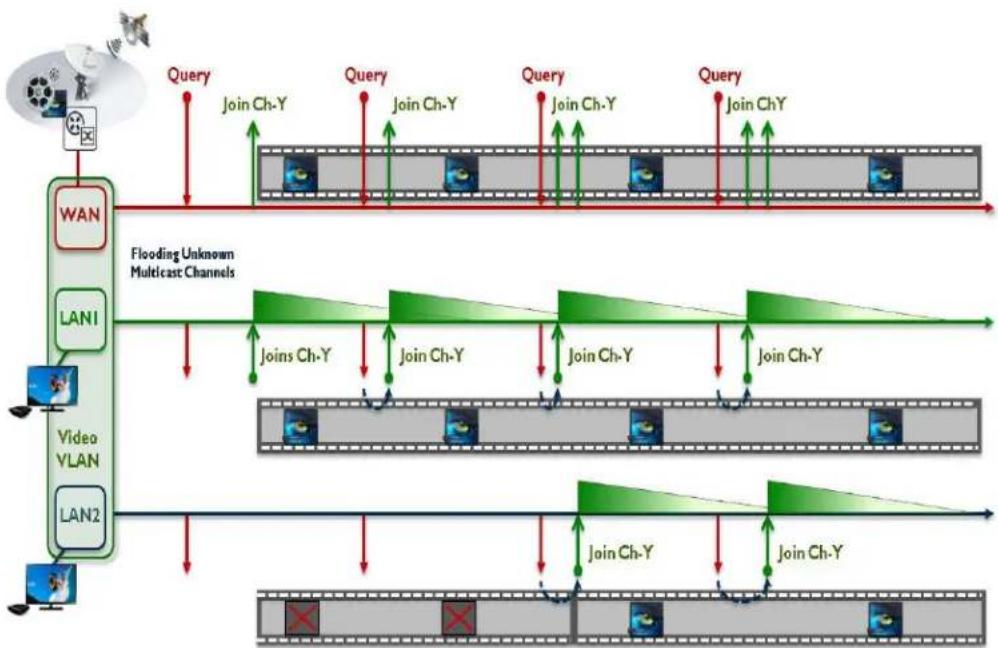
flowchart
graph TD
    A["WAN"] --> B["Flooding Unknown Multicast Channels"]
    B --> C["Video VLAN"]
    C --> D["LAN1"]
    D --> E["LAN2"]
    E --> F["Join Ch-Y"]
    F --> G["Join Ch-Y"]
    G --> H["Join Ch-Y"]
    H --> I["Join Ch-Y"]
    I --> J["Join Ch-Y"]
    J --> K["Join Ch-Y"]
    K --> L["Join Ch-Y"]
    L --> M["Join Ch-Y"]
    M --> N["Join Ch-Y"]
    N --> O["Join Ch-Y"]
    O --> P["Join Ch-Y"]
    P --> Q["Join Ch-Y"]
    Q --> R["Join Ch-Y"]
    R --> S["Join Ch-Y"]
    S --> T["Join Ch-Y"]
    T --> U["Join Ch-Y"]
    U --> V["Join Ch-Y"]
    V --> W["Join Ch-Y"]
    W --> X["Join Ch-Y"]
    X --> Y["Join Ch-Y"]
FIGURE 4-1 IGMPSnooping
4.2.1.2 Leave operation
When a STB sends a IGMP leave message for a Multicast stream, the system will detect on which LAN interface the IGMP leave message has been received.
At this point any static MAC address matching the Multicast MAC address, will be removed from the switch FDB. This immediately causes the drop of the received Multicast stream for that specific LAN interface.
Then the message is forwarded as it is (same STB source IP/MAC addresses) upstream to the Multicast network. Depending on the design of the Multicast network then the stream could be stopped or additional actions could be taken to discover any outstanding host still interested to receive that specific stream.
4.2.1.2.1 Expiring of a Multicast entry
The IGMP module is designed to age out Multicast streams in case a Set-Top-Box or Multicast host does not reply to IGMP Generic or Specific Queries and has not sent any leave message for an existing Multicast stream (or because the leave message is lost in the communication).
To avoid that an incoming stream remains active on the LAN interface, the system starts a timer when the Report message is received.
If during the query-interval period, the Set-Top-Box does not renew the join to the existing Multicast stream by sending a corresponding IGMP report message, after a period of time equals the query-interval * robustness-variable + query-max-response-time, the static MAC address matching the stream Multicast MAC address, will be removed from the switch FDB.
This immediately causes the drop of the received Multicast stream for that specific LAN interface.
Note: When IGMP Snoop Only mode is configured, the fast-leave attribute does not take effect.
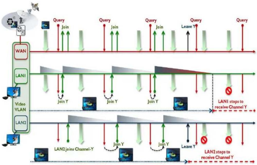
flowchart
graph TD
    A["WAN"] --> B["Video VLAN"]
    B --> C["LAN1"]
    C --> D["LAN2"]
    D --> E["Join Y"]
    E --> F["Join Y"]
    F --> G["Join Y"]
    G --> H["Join Y"]
    H --> I["Leave Y"]
    I --> J["Join Y"]
    J --> K["Join Y"]
    K --> L["Join Y"]
    L --> M["Join Y"]
    M --> N["Join Y"]
    N --> O["Join Y"]
    O --> P["Join Y"]
    P --> Q["Join Y"]
    Q --> R["Join Y"]
    R --> S["Join Y"]
    S --> T["Join Y"]
    T --> U["Join Y"]
    U --> V["Join Y"]
    V --> W["Join Y"]
    W --> X["Join Y"]
    X --> Y["Join Y"]
    Y --> Z["Join Y"]
    Z --> AA["Join Y"]
    AA --> AB["Join Y"]
    AB --> AC["Join Y"]
    AC --> AD["Join Y"]
    AD --> AE["Join Y"]
    AE --> AF["Join Y"]
    AF --> AG["Join Y"]
    AG --> AH["Join Y"]
    AH --> AI["Join Y"]
    AI --> AJ["Join Y"]
    AJ --> AK["Join Y"]
    AK --> AL["Join Y"]
    AL --> AM["Join Y"]
    AM --> AN["Join Y"]
    AN --> AO["Join Y"]
    AO --> AP["Join Y"]
    AP --> AQ["Join Y"]
    AQ --> AR["Join Y"]
    AR --> AS["Join Y"]
    AS --> AT["Join Y"]
    AT --> AU["Join Y"]
    AU --> AV["Join Y"]
    AV --> AW["Join Y"]
    AW --> AX["Join Y"]
    AX --> AY["Join Y"]
    AY --> AZ["Join Y"]
    AZ --> BA["Join Y"]
    BA --> BB["Join Y"]
    BB --> BC["Join Y"]
    BC --> BD["Join Y"]
    BD --> BE["Join Y"]
    BE --> BF["Join Y"]
    BF --> BG["Join Y"]
    BG --> BH["Join Y"]
    BH --> BI["Join Y"]
    BI --> BJ["Join Y"]
    BJ --> BK["Join Y"]
    BK --> BL["Join Y"]
    BL --> BM["Join Y"]
    BM --> BN["Join Y"]
    BN --> BO["Join Y"]
    BO --> BP["Join Y"]
    BP --> BQ["Join Y"]
    BQ --> BR["Join Y"]
    BR --> BS["Join Y"]
    BS --> BT["Join Y"]
    BT --> BU["Join Y"]
    BU --> BV["Join Y"]
    BV --> BW["Join Y"]
    BW --> BX["Join Y"]
    BX --> BY["Join Y"]
    BY --> BZ["Join Y"]
    BZ --> CA["Join Y"]
    CA --> CB["Join Y"]
    CB --> CC["Join Y"]
    CC --> CD["Join Y"]
    CD --> CE["Join Y"]
    CE --> CF["Join Y"]
    CF --> CG["Join Y"]
    CG --> CH["Join Y"]
    CH --> CI["Join Y"]
    CI --> CJ["Join Y"]
    CJ --> CK["Join Y"]
    CK --> CL["Join Y"]
    CL --> CM["Join Y"]
    CM --> CN["Join Y"]
    CN --> CO["Join Y"]
    CO --> CP["Join Y"]
    CP --> CQ["Join Y"]
    CQ --> CR["Join Y"]
    CR --> CS["Join Y"]
    CS --> CY["Join Y"]
    CY --> CZ["Join Y"]
    CZ --> DA["Join Y"]
    DA --> DB["Join Y"]
    DB --> DC["Join Y"]
    DC --> DD["Join Y"]
    DD --> DE["Join Y"]
    DE --> DF["Join Y"]
    DF --> DG["Join Y"]
    DG --> DH["Join Y"]
    DH --> DI["Join Y"]
    DI --> DJ["Join Y"]
    DJ --> DK["Join Y"]
    DK --> DL["Join Y"]
    DL --> DM["Join Y"]
    DM --> DN["Join Y"]
    DN --> DO
FIGURE 4-2 Expiring of a Multicast entry
Example
In this example the video service is provided via video vlan VID=205. The iMG is configured for IGMP Snoop Only mode. WAN (port1.0.6) is tagged on VID=205 while LAN interfaces (port1.0.1-port1.0.5) belong to video VLAN as untagged interfaces:
First configure the video In this example the video VLAN has VID=205:
awplus# configure terminal
awplus(config)# vlan database
awplus(config-vlan)# vlan 205 name video
awplus(config-vlan)# exit
awplus(config)# interface port1.0.6
awplus(config-if)# switchport mode trunk
awplus(config-if)# switchport trunk allowed vlan add 205
awplus(config-if)# switchport trunk native vlan none
awplus(config-if)# exit
awplus(config)# interface port1.0.1-port1.0.5
awplus(config-if)# switchport mode access
awplus(config-if)# switchport access vlan 205
awplus(config-if)# exit
Then enable IGMP snooping on video vlan 205
awplus(config)# interface vlan205
awplus(config-if)# ip igmp snooping
awplus(config-if)# exit
And disable IGMP proxy mode (that it's enabled by default)
awplus(config)# no ip igmp proxy-service
awplus(config)# ip igmp version 2
awplus(config)# end
4.2.2 IGMP Proxy Mode
4.2.2.1 Join operation
The main characteristic of IGMP Proxy mode is that there is a complete separation of the IGMP signaling messages receive/transmitted between the upstream Multicast network and IGMP signaling messages receive/transmitted within the home video network.
Each IGMP Report/Leave message sent by internal set-top-boxes or Multicast hosts are not forwarded upstream but are terminated on the iMG IGMP module. The same happens for IGMP Queries received from the from the Multicast network.
If the IGMP message is a Report to a Multicast stream, the system adds a MAC static entry corresponding to the joined Multicast address in the switch FDB.
If no other hosts have already joined the same Multicast stream, the message is sent upstream to the Multicast network. Before the message is sent, the source MAC/IP address is replaced with the iMG MAC address and with the IP address of the vlan where IGMP has been enabled.
Note: If a previous hosts has already joined the same Multicast channel, than the Report received from the STB is retained and it's not forwarded upstream avoiding in this way to flood the network with redundant IGMP messages.
On the LAN side, for each IGMP Report received, the IGMP task updates an internal Multicast table that keeps track of the active streams, Multicast hosts and channels timeouts.
To refresh the content of the Multicast table, IGMP Proxy module sends periodically query messages to the internal LAN interfaces to discover any active Multicast host.
The frequency of these IGMP Query messages is given by the query-interval timer and it's completely independent from the frequency IGMP queries are received from the Multicast network.
Also the Max Response Time value contained in the Query message is configurable by the iMG IGMP module via the query-max-response-time attribute.
On the WAN side, at the reception of a Generic Query from the Multicast network, the IGMP Proxy module will answer with the list of the channels stored on its Multicast channels table.
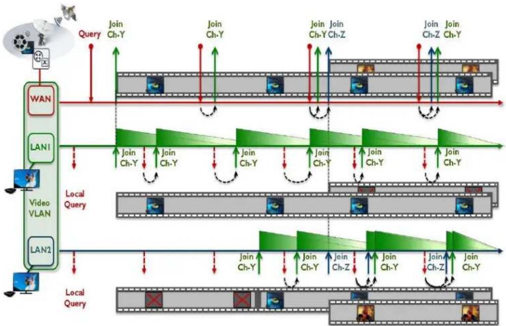
flowchart
graph TD
    A["WAN"] --> B["Local Query"]
    C["LAN1"] --> B
    D["Video VLAN"] --> B
    E["LAN2"] --> B
    B --> F["Join Ch-Y"]
    B --> G["Join Ch-Y"]
    B --> H["Join Ch-Y"]
    B --> I["Join Ch-Z"]
    B --> J["Join Ch-Z"]
    B --> K["Join Ch-Y"]
    F --> L["Local Query"]
    G --> L
    H --> L
    I --> L
    J --> L
    K --> L
    L --> M["Local Query"]
    M --> N["Join Ch-Y"]
    M --> O["Join Ch-Z"]
    M --> P["Join Ch-Z"]
FIGURE 4-3 Join operation
4.2.2.2 Leave operation
If the IGMP message is a Leave from a Multicast stream, the system will detect on which LAN interface the IGMP leave message has been received.
At this point, depending on the setting of the fast-leave attribute, the IGMP module can acts in two different ways:
If fast-leave is enabled, the static MAC address matching the stream Multicast MAC address, will be removed from the switch FDB (only for the LAN that has received the IGMP leave message).
This immediately causes the drop of the received Multicast stream for that specific LAN interface.
If there are no other hosts existing in the Multicast channels table for that specific channel, then a leave message is sent upstream to the Multicast network. The leave message will have the iMG MAC address and IP address of the vlan where IGMP has been enabled hiding in this way any information about the internal host.
If fast-leave is disabled, before purging the static MAC address matching the stream Multicast MAC address, the IGMP Proxy module will send one or more Specific IGMP Queries to check if there are internal hosts that are still interested to receive the channel going to be closed.
The number of Specific IGMP Queries is configurable by the robustness variable.
If there are no hosts replying to the Specific IGMP Queries, then the static MAC address matching the stream Multicast MAC address will be removed from the switch FDB (only for the LAN that has received the IGMP leave message). This causes the drop of the received Multicast stream for that specific LAN interface.
If there are no other hosts existing in the Multicast channels table for that specific channel, then a leave message is sent upstream to the Multicast network. The leave message will have the iMG MAC address and IP address of the vlan where IGMP has been enabled hiding in this way any information about the internal host
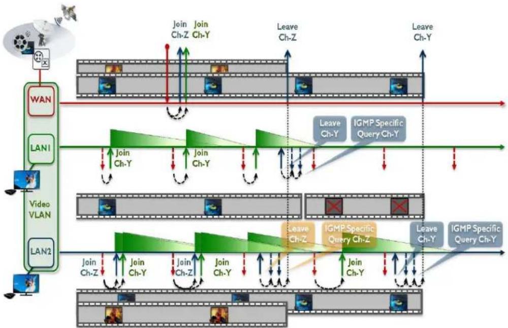
flowchart
graph TD
    A["WAN"] --> B["Join Ch-Z"]
    C["LAN1"] --> D["Join Ch-Y"]
    E["Video VLAN"] --> F["Join Ch-Z"]
    G["LAN2"] --> H["Join Ch-Y"]
    I["Leave Ch-Z"] --> J["Leave Ch-Y"]
    K["Leave Ch-Y"] --> L["Leave Ch-Y"]
    M["Leave Ch-Y"] --> N["Leave Ch-Y"]
    O["Leave Ch-Z"] --> P["Leave Ch-Y"]
    Q["Leave Ch-Y"] --> R["Leave Ch-Y"]
    S["Leave Ch-Z"] --> T["Leave Ch-Y"]
    U["Leave Ch-Y"] --> V["Leave Ch-Y"]
    W["Leave Ch-Z"] --> X["Leave Ch-Y"]
    Y["Leave Ch-Y"] --> Z["Leave Ch-Y"]
    AA["Leave Ch-Z"] --> AB["Leave Ch-Y"]
    AC["Leave Ch-Y"] --> AD["Leave Ch-Y"]
    AE["Leave Ch-Z"] --> AF["Leave Ch-Y"]
    AG["Leave Ch-Y"] --> AH["Leave Ch-Y"]
    AI["Leave Ch-Z"] --> AJ["Leave Ch-Y"]
    AK["Leave Ch-Y"] --> AL["Leave Ch-Y"]
    AM["Leave Ch-Z"] --> AN["Leave Ch-Y"]
    AO["Leave Ch-Y"] --> AP["Leave Ch-Y"]
    AQ["Leave Ch-Z"] --> AR["Leave Ch-Y"]
    AS["Leave Ch-Y"] --> AT["Leave Ch-Y"]
    AU["Leave Ch-Z"] --> AV["Leave Ch-Y"]
    AW["Leave Ch-Y"] --> AX["Leave Ch-Y"]
    AY["LAN1"] --> AZ["Join Ch-Y"]
    BA["LAN2"] --> BB["Join Ch-Z"]
    BC["Video VLAN"] --> BD["Join Ch-Y"]
    BE["Video VLAN"] --> BF["Join Ch-Z"]
    BG["Video VLAN"] --> BH["Join Ch-Y"]
    BI["Video VLAN"] --> BJ["Join Ch-Z"]
    BK["Video VLAN"] --> BL["Join Ch-Y"]
    BM["Video VLAN"] --> BN["Join Ch-Z"]
    BO["Video VLAN"] --> BP["Join Ch-Y"]
    BQ["LAN1"] --> BR["Join Ch-Y"]
    BS["LAN2"] --> BT["Join Ch-Z"]
    BU["Video VLAN"] --> BV["Join Ch-Z"]
    BW["Video VLAN"] --> BX["Join Ch-Z"]
    BY["Video VLAN"] --> BZ["Join Ch-Z"]
    CA["Video VLAN"] --> CB["Join Ch-Z"]
    CC["Video VLAN"] --> CD["Join Ch-Z"]
    CE["Video VLAN"] --> CF["Join Ch-Z"]
    DG["Video VLAN"] --> DH["Join Ch-Z"]
    DI["Video VLAN"] --> DJ["Join Ch-Z"]
    DK["Video VLAN"] --> DL["Join Ch-Z"]
    DM["Video VLAN"] --> DE["Join Ch-Z"]
    DF["Video VLAN"] --> DG
    DG --> DG
FIGURE 4-4 Leave operation
4.2.2.3 Expiring of a Multicast entry
Similarly to IGMP Snoop Only mode, the IGMP module ages out the learned Multicast entries in case a Set-Top-Box or Multicast host does not reply to IGMP Queries (generic or specific) and has not sent any leave message for an existing Multicast stream (because it was turned off or because the leave message is lost in the communication).
The time a Multicast entry is kept in the IGMP database equals the query-interval * robustness-variable + query-max-response-time.
This timer is restarted every time the IGMP module receives a Report message.
Differently from IGMP Snoop Only mode, when the timer expires, the iMG generates upstream an IGMP Leave message corresponding to the Multicast address of the entry that is aged out.
The Leave message is sent only if it is the only existing entry in the IGMP database for the Multicast stream. If the IGMP module has registered other ports or hosts still receiving that Multicast stream, than the Leave message is not sent (this to avoid that the network stops sending the stream while other hosts are still wishing to receive it).
Example
In this example the video service is provided via video vlan VID=205. The iMG is configured for IGMP Proxy mode. WAN (port1.0.6) is tagged on VID=205 while LAN interfaces (port1.0.1-port1.0.5) belong to video VLAN as untagged interfaces:
First configure the video vlan.
awplus# configure terminal
awplus(config)# vlan database
awplus(config-vlan)# vlan 205 name video
awplus(config-vlan)# exit
awplus(config)# interface port1.0.6
awplus(config-if)# switchport mode trunk
Multicast Applications IGMP Snooping on iMG
awplus(config-if)# switchport trunk allowed vlan add 205
awplus(config-if)# switchport trunk native vlan none
awplus(config-if)# exit
awplus(config)# interface port1.0.1-port1.0.5
awplus(config-if)# switchport mode access
awplus(config-if)# switchport access vlan 205
awplus(config-if)# exit
Then enable IGMP snooping on video vlan 205
awplus(config)# interface vlan205
awplus(config-if)# ip igmp snooping
awplus(config-if)# exit
And enable IGMP proxy mode (this is enabled by default and it's here reported just for clarity)
awplus(config)# ip igmp proxy-service
awplus(config)# ip igmp version 2
awplus(config)# end
4.2.3 IGMP Proxy Routed Mode (Multicast Acceleration)
IGMP Proxy mode supports an extended mode called Routed Mode or also Multicast Acceleration that allows the routing (pseudo routing) of Multicast traffic between VLANs.
In Proxy Routed Mode the local user network is isolated from the access network: a DHCP server configured on the iMG is typically used to assign local IP addresses to the user network and NAT is then adopted to allow the access to the service provider network.
Proxy Routed Mode allows Multicast streams received at the WAN interface of the service provider video network to be routed internally to the private user network.
Multicast Acceleration does not perform a true routing of Multicast frames, i.e. the IP TTL value is not decremented and the Ethernet header is left unchanged too. It uses the properties of the switch silicon for wire speed throughput performances.
Join, Leave and expire operations are the same as for IGMP Proxy Mode.
The only difference is that the Source IP address of the IGMP messages sent internally is the IP address of the Internal IP interface where usually the DHCP server runs.
So, the IGMP Report and Leave messages sent upstream will have the IP address of the WAN video network and the IGMP query messages sent downstream will have the IP address of the LAN Internal home network where typically the DHCP server runs.
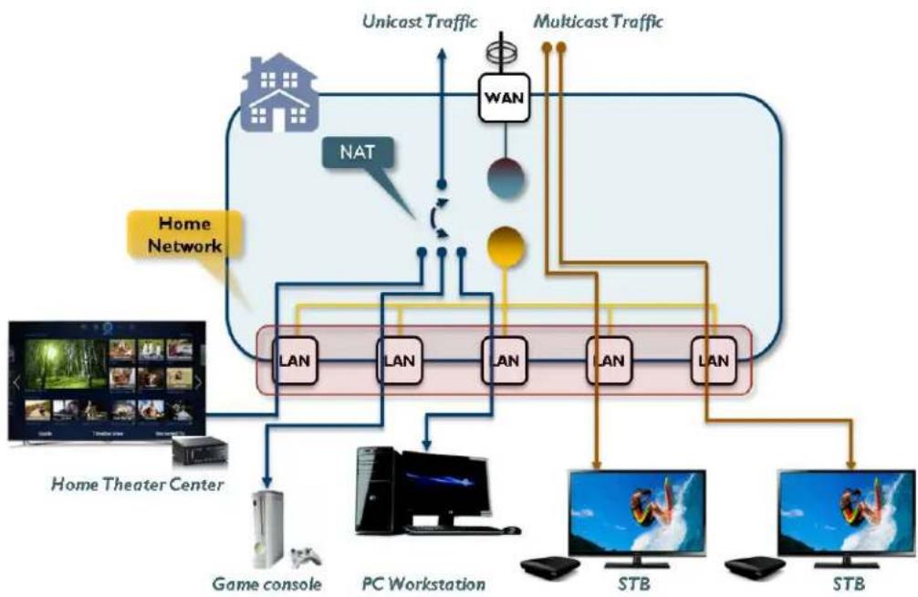
flowchart
graph TD
    A["Home Theater Center"] --> B["Game console"]
    B --> C["PC Workstation"]
    C --> D["STB"]
    D --> E["STB"]
    F["NAT"] --> G["WAN"]
    G --> H["UNicast Traffic"]
    H --> I["Multicast Traffic"]
    I --> J["LAN"]
    J --> K["LAN"]
    K --> L["LAN"]
    L --> M["LAN"]
    M --> N["LAN"]
    N --> O["LAN"]
    O --> P["STB"]
    Q["Home Network"] --> R["UNicast Traffic"]
    R --> S["Multicast Traffic"]
    S --> T["LAN"]
    T --> U["LAN"]
    U --> V["LAN"]
    V --> W["LAN"]
    W --> X["LAN"]
    X --> Y["LAN"]
    Y --> Z["LAN"]
    Z --> AA["LAN"]
    AA --> AB["LAN"]
    AB --> AC["LAN"]
    AC --> AD["LAN"]
    AD --> AE["LAN"]
    AE --> AF["LAN"]
    AF --> AG["LAN"]
    AG --> AH["LAN"]
    AH --> AI["LAN"]
    AI --> AJ["LAN"]
    AJ --> AK["LAN"]
    AK --> AL["LAN"]
    AL --> AM["LAN"]
    AM --> AN["LAN"]
    AN --> AO["LAN"]
    AO --> AP["LAN"]
    AP --> AQ["LAN"]
    AQ --> AR["LAN"]
    AR --> AS["LAN"]
    AS --> AT["LAN"]
    AT --> AU["LAN"]
    AU --> AV["LAN"]
    AV --> AW["LAN"]
    AW --> AX["LAN"]
    AX --> AY["LAN"]
    AY --> AZ["LAN"]
    AZ --> BA["LAN"]
    BA --> BB["LAN"]
    BB --> BC["LAN"]
    BC --> BD["LAN"]
    BD --> BE["LAN"]
    BE --> BF["LAN"]
    BF --> BG["LAN"]
    BG --> BH["LAN"]
    BH --> BI["LAN"]
    BI --> BJ["LAN"]
    BJ --> BK["LAN"]
    BK --> BL["LAN"]
    BL --> BM["LAN"]
    BM --> BN["LAN"]
    BN --> BO["LAN"]
    BO --> BP["LAN"]
    BP --> BQ["LAN"]
    BQ --> BR["LAN"]
    BR --> BS["LAN"]
    BS --> BT["LAN"]
    BT --> BU["LAN"]
    BU --> BV["LAN"]
    BV --> BW["LAN"]
FIGURE 4-5 IGMP Proxy Routed Mode (Multicast Acceleration)
Example
In this example the Internet and Video services share the same service provider VALN VID=205.
The users has a Media Center Box on a local private vlan VID=100.
First configure the video vlan.
awplus# configure terminal
awplus(config)# vlan database
awplus(config-vlan)# vlan 205 name video
awplus(config-vlan)# exit
awplus(config)# interface port1.0.6
awplus(config-if)# switchport mode trunk
awplus(config-if)# switchport trunk allowed vlan add 205
awplus(config-if)# switchport trunk native vlan none
awplus(config-if)# exit
awplus(config)# interface vlan205
awplus(config-if)# ip address dhcp
awplus(config-if)# ip dhcp client request 3
awplus(config-if)# ip dhcp client request 6
awplus(config-if)# ip dhcp client request 15
awplus(config-if)# ip nat enable
Then enable IGMP proxy service on the Internet/Data vlan. This setting tells the system to enable the support for Multicast Acceleration:
Multicast Applications IGMP Snooping on iMG
awplus# configure terminal
awplus(config)# interface vlan205
awplus(config-if)# ip igmp snooping
awplus(config-if)# ip igmp proxy-service
awplus(config)# end
Then create the internal VLAN:
awplus# configure terminal
awplus(config)# vlan database
awplus(config-vlan)# vlan 100 name internal
awplus(config-vlan)# exit
awplus(config)# interface port1.0.1-port1.0.5
awplus(config-if)# switchport mode access
awplus(config-if)# switchport access vlan 100
awplus(config-if)# end
And finally configure the DHCP server on Internal VLAN and enable IGMP snooping support on it:
awplus# configure terminal
awplus(config)# interface vlan100
awplus(config-if)# ip address 192.168.100.1/24
awplus(config-if)# ip dhcp pool
awplus(dhcp-config)# range 192.168.100.10 192.168.100.20
awplus(dhcp-config)# subnet 255.255.255.0
awplus(dhcp-config)# lease 0 0 15
awplus(dhcp-config)# exit
awplus(config-if)# ip dhcp server
awplus(config-if)# ip igmp snooping
awplus(config-if)# exit
awplus(config)# ip igmp version 2
awplus(config)# end
4.2.4 Multicast Command List
This chapter provides an alphabetical reference of configure, clear, and show commands related to Internet Group Management Protocol (IGMP).
Table 4-1: Switching Commands
| Commands |
| ip igmp last-member-query-interval |
| ip igmp limit |
| ip igmp proxy-service |
| ip igmp proxy-service (interface level) |
| ip igmp query-interval |
| ip igmp query-max-response-time |
| ip igmp robustness-variable |
| ip igmp snooping |
| ip igmp snooping fast-leave |
| ip igmp version |
| show ip igmp |
| show ip igmp groups |
IP IGMP LAST-MEMBER-QUERY-INTERVAL
Syntax
ip igmp last-member-query-interval
no ip igmp last-member-query-interval
Description
This command configures the frequency at which the router sends IGMP specific query messages after a Leave message has been received.
IGMP specific query messages are sent only when IGMP is configured for Proxy Mode or Multicast Acceleration Mode.
Use the no variant of this command to set this frequency to the default value
Feature IGMP Multicast Commands
Mode Global configuration mode
Release 4.1
Options
| Option Description Range | Default Value | ||
| The duration in tenth of seconds at which IGMP group-specific host query messages are sent | 1-2147483647 10 | (tenth of seconds) | |
Note NA
Example
In the following example IGMP group-specific host query message is configured to 2 seconds (20 tenths of seconds)::
awplus> enable
awplus# configure terminal
awplus(config)# ip igmp last-member-query-interval 20
IP IGMP LIMIT
Syntax
ip igmp limit
no ip igmp limit
This command configures the limit on the maximum number of group membership entries managed by the IGMP module.
Use the no variant of this command to reset the limit to the default value
Mode Global configuration mode
Feature IGMP Multicast Commands
Mode Global configuration mode
Release 4.1
Options
| Option Description Range | Default Value | |
| Maximum number of group membership entries 0-4095 64 |
Note NA
Example
The following example configures an IGMP limit of 100 group membership entries on the IGMP:
awplus# configure terminal
awplus(config)# ip igmp limit 100
IP IGMP PROXY-SERVICE
Syntax
ip igmp proxy-service
no ip igmp proxy-service
This command enables and configures IGMP module to work in Proxy Mode.
Feature IGMP Multicast Commands
Mode Global configuration mode
Release 4.2
Options NA
Example The following example enables IGMP Proxy Mode:
awplus# configure terminal
awplus(config)# ip igmp proxy-service
Multicast Applications IGMP Snooping on iMG
IP IGMP PROXY-SERVICE (INTERFACE LEVEL)
Syntax
ip igmp proxy-service no ip igmp proxy-service
Description
This command is used to identify this VLAN interface as the Multicast proxy, and sets the Multicast accelerated mode on the WAN.
Use the no variant of this command to remove the designation of the VLAN interface as an upstream proxy-service interface.
Feature IGMP Multicast Commands
Mode Interface Config (VLANs).
Release 4.2
Options NA
Note NA
Example The following example designates the vlan1 interface as the upstream proxy-service interface:
awplus# configure terminal Enter configuration commands, one per line. End with CNTL/Z. awplus(config)# interface vlan205 awplus(config-if)# ip igmp proxy-service
IP IGMP QUERY-INTERVAL
Syntax
ip igmp query-interval
no ip igmp query-interval
Description
This command configures the period for sending IGMP General Query messages. The IGMP query interval specifies the time between IGMP General Query messages being sent.
Use the no variant of this command to return to the default query interval period
This command applies to interfaces configured for IGMP. Note that the IGMP query interval is automatically set to a greater value than the IGMP query max response time.
For example, if you set the IGMP query max response time to 2 seconds using the ip igmp query-max-response-time command, and the IGMP query interval is currently less than 3 seconds, then the IGMP query interval period will be automatically reconfigured to be 3 seconds, so it is greater than the IGMP query maximum response time.
Use the ip igmp query-interval command when a non-default interval for IGMP General Query messages is required.
The ip igmp query-holdtime command can occasionally delay the sending of IGMP Queries
Feature IGMP Multicast Commands
Mode Global configuration mode
Release 4.1
Options
| Option Description Range | Default Value | ||
| Query interval value expressed in seconds at which IGMP host query messages are sent | 0-2147483647 | 125 | |
Note
IGMP query interval must be greater than IGMP query maximum response time
Example
The following example changes the period between IGMP host-query messages to 3 minutes (180 seconds):
awplus# configure terminal
Enter configuration commands, one per line. End with CNTL/Z.
awplus(config)# ip igmp query-interval 180
Example The following example resets the period between sending IGMP host-query messages to the default (125 seconds):
awplus# configure terminal
Enter configuration commands, one per line. End with CNTL/Z.
awplus(config-if)# no ip igmp query-interval
IP IGMP QUERY-MAX-RESPONSE-TIME
Syntax
ip igmp query-max-response-time
no ip igmp query-max-response-time
Description
This command configures the maximum response time advertised in IGMP Queries.
Use the no variant of this command to restore the default value.
This command applies to interfaces configured for IGMP. Note that the IGMP query interval is automatically set to a greater value than the IGMP query maximum response time.
For example, if you set the IGMP query interval to 3 seconds using the ip igmp query-interval command, and the current IGMP query interval is less than 3 seconds, then the IGMP query maximum response time will be automatically reconfigured to be 2 seconds, so it is less than the IGMP query interval time.
To get the network to converge faster, use the ip igmp query-max-response-time command and set a low response time value, such as one or two seconds, so that the clients will respond immediately with a report as a response to the IGMP Queries
Feature IGMP Multicast Commands
Mode Global configuration mode)
Release 4.1
Options
| Option Description Range | Default Value | ||
| Response time value expressed in tenths of seconds.Maximum response time advertised in IGMP queries. | 0-2147483647 | 10 (1 second) | |
Note
The IGMP query maximum response time must be less than the IGMP query interval.
Example
The following example configures a maximum response time of 8 seconds:
awplus# configure terminal
Enter configuration commands, one per line. End with CNTL/Z.
awplus(config)# ip igmp query-max-response-time 80
Example
The following example restores the default maximum response time of 10 seconds:
awplus# configure terminal
Enter configuration commands, one per line. End with CNTL/Z.
awplus(config)# ip igmp query-max-response-time
IP IGMP ROBUSTNESS-VARIABLE
Syntax
ip igmp robustness-variable <2-2147483647>
no ip igmp robustness-variable
Description
This command sets the value for the network robustness, allowing tuning based upon expected packet loss on the network.
Use the no variant of this command to return to the default value on an interface.
Feature IGMP Multicast Commands
Mode Global configuration mode
Release 4.1
Options
| Option Description Range | Default Value | ||
| robustness-variable | This robustness value will modify the time, in proxy mode only, between the leave on the LAN facing network and the leave being sent on the WAN facing network will be robustness times the lastmemberqueryintvl. It functions by forcing multiple IGMP Packet transmissions. | 2-2147483647 2 | |
Note NA
Example To set the robustness variable to 3, enter the following:
awplus# configure terminal
Enter configuration commands, one per line. End with CNTL/Z.
awplus(config)# ip igmp robustness-variable 3
Multicast Applications IGMP Snooping on iMG
IP IGMP SNOOPING
Syntax
ip igmp snooping no ip igmp snooping
Description
This command enables IGMP Snooping. When this command is used in the Global Configuration mode, IGMP Snooping is enabled at the switch level. When this command is used in Interface Configuration mode, IGMP Snooping is enabled for the specified VLANs.
Use the no variant of this command to disable IGMP Snooping on a specified interface.
By default, IGMP Snooping is enabled globally and disabled on all VLANs.
For IGMP snooping to operate on particular VLAN interfaces, it must be enabled both globally by using this command in Global Configuration mode, and on individual VLAN interfaces by using this command in Interface Configuration mode (both are enabled by default.)
Feature IGMP Multicast Commands
Mode Interface Config (VLANs)
Release 4.1
Options NA
Note NA
Example To enable IGMP snooping, enter the following:
awplus# configure terminal Enter configuration commands, one per line. End with CNTL/Z. awplus(config)# interface vlan1 awplus(config-if)# ip igmp snooping
IP IGMP SNOOPING FAST-LEAVE
Syntax
ip igmp snooping fast-leave no ip igmp snooping fast-leave
Description
This command enables IGMP Snooping fast-leave processing. Fast-leave processing is analogous to immediate-leave processing; the IGMP group-membership entry is removed as soon as an IGMP leave group message is received, without sending out a group-specific query.
Use the no variant of this command to disable fast-leave processing By default, snooping fast-leave processing is enabled.
Feature IGMP Multicast Commands
Mode Global configuration mode
Release 4.1
Options NA
Note NA
Example This example shows how to enable fast-leave processing on a VLAN:
awplus# configure terminal Enter configuration commands, one per line. End with CNTL/Z. awplus(config)# ip igmp snooping fast-leave
IP IGMP VERSION
Syntax ip igmp version <1-3> no ip igmp version
Description This command sets the current IGMP version (IGMP version 1, 2 or 3) on an interface.
Use the no variant of this command to return to the default version.
This command applies to VLAN interfaces configured for IGMP
Feature IGMP Multicast Commands
Mode Global configuration mode
Release 4.1
Options
| Option Description Range | Default Value | |
| <1-3> IGMP protocol version number. NA 3 |
Note NA
Example To set the IGMP version, enter the following:
awplus# configure terminal Enter configuration commands, one per line. End with CNTL/Z. awplus(config)# ip igmp version 2
SHOW IP IGMP
Syntax show ip igmp
Description This command displays the status of IGMP.
Feature IGMP Multicast Commands
Mode Privileged Exec Mode
Release 4.1
Options NA
Note NA
Example The following command displays IGMP status:
awplus# show ip igmp
IGMP snooping is enabled for vlan144
IGMP proxy mode is enabled
IGMP Routed Proxy service is not enabled
IGMP version is 2
IGMP Max number of groups is 64
IGMP robustness variable is 2
IGMP query interval is 125 seconds
IGMP max query response time is 10 (1/10 seconds)
IGMP Last member query response interval is 10 (1/10 seconds)
Note IGMP snooping fast-leave is enabled
Example The following command displays iMG1425W IGMP statistics:
iMG1425W# show ip igmp snooping statistics
IGMP Snooping statistics
#Channels: 1
#Hosts: 1
Query Rx: 0 GS Query Rx: 0 V3 Query Tot Rx: 0
Join Rx: 0 Leave Rx: 0 V3 Report Rx 0
Total Rx: 0
Query Tx: 0 GS Query Tx: 0 V3 Query Tot Tx: 0
Join Tx: 0 Leave Tx: 0 V3 Report TX 0
Total Tx: 0
Group Address Interface Port Reporter Uptime
LastJoin Expires
224.2.2.50 vlan2 dot11radio1.0.1 192.168.100.11 01:55:30
00:00:48 00:02:21
Example The following command displays iMG1425W snooping statistics interface dot11radio1.0.1:
IGMP Snooping statistics
#Channels: 1
#Hosts: 1
Query Rx: 0 GS Query Rx: 0 V3 Query Tot Rx: 0
Join Rx: 0 Leave Rx: 0 V3 Report Rx 0
Total Rx: 0
Query Tx: 0 GS Query Tx: 0 V3 Query Tot Tx: 0
Join Tx: 0 Leave Tx: 0 V3 Report TX 0
Total Tx: 0
Multicast Applications IGMP Snooping on iMG
| Group Address | Interface | Port | Reporter | Uptime | ||
| LastJoin Expires | ||||||
| 224.2.2.50 | vlan2 | dot11radio1.0.1 | 192.168.100.11 | 01:55:40 | ||
| 00:00:59 | 00:02:10 | |||||
| Example | The following command displays iMG1425W snooping statistics interface dot11radio1.0.1 for wireless ports: | |||||
| pre-existing cli commands still working on all devices: show ip igmp snooping statistics interface port1.0.x show ip igmp snooping statistics interface vlanxxx | ||||||
| Example | The following command displays iMG2524H snooping statistics for the HPNA port: | |||||
| awplus# show ip igmp snooping statistics interface hpnal.0.1 | ||||||
| IGMP Snooping statistics #Channels: 3 #Hosts: 2 Query Rx: 0 GS Query Rx: 0 V3 Query Tot Rx: 0 Join Rx: 0 Leave Rx: 0 V3 Report Rx 0 Total Rx: 0 Query Tx: 0 GS Query Tx: 0 V3 Query Tot Tx: 0 Join Tx: 0 Leave Tx: 0 V3 Report TX 0 Total Tx: 0 | ||||||
| Group Address | Interface | Port | Reporter | Uptime | LastJoin | Expires |
| 225.10.10.10 | vlan100 | hpnal.0.1 | 192.168.100.11 | 25:00:59 | 00:00:51 | 00:03:28 |
| 224.2.2.62 | vlan100 | hpnal.0.1 | 192.168.100.11 | 00:31:36 | 00:00:51 | 00:03:28 |
| 224.2.2.52 | vlan100 | hpnal.0.1 | 192.168.100.10 | 00:06:09 | 00:00:50 | 00:03:29 |
SHOW IP IGMP GROUPS
Syntax show ip igmp groups
Description This command displays the Multicast group entries registered on each interface and the expire timeout..
Feature IGMP Multicast Commands
Mode Global configuration Mode
Release 4.3
Options NA
Note NA
Example The following example displays the IGMP entries for a iMG1425W where three Multicast host are connected on LAN port1.0.5 and on Wireless interface:
awplus# awplus# show ip igmp groups
IGMP IGMP Connected Group Membership
| Group Address | Interface | Uptime | Expires | Last Reporter |
| 239.255.255.254 | port1.0.5 | 00:21:30 | 00:03:57 | 10.17.90.1 |
| 224.0.1.60 | port1.0.5 | 00:21:24 | 00:03:54 | 10.17.90.31 |
| 239.255.255.100 | port1.0.5 | 00:19:52 | 00:02:38 | 10.17.90.78 |
| 224.2.2.52 | dot11radio1.0.1 | 00:02:56 | 00:02:30 | 10.17.90.131 |
5. Access and Security
The Access and Security functions of the iMG include the following:
• Quality of Service Model
• QoS Command List
- Secure Shell Protocol
- SSH Command List
• Security (Trigger, Firewall, Access Control List, Logging)
• Security Command List
5.1 Quality of Service Model
5.1.1 Address management
The primary function of the layer 2 switch is to receive good packets from the ports, process them and forward them to the appropriate ports for transmission. This frame processing involves the Ingress Policy, Queue Controller, Output Queues and Egress Policy.
The normal packet flow involves learning how to switch packets only to the correct ports. The switch learns which port and end station is connected to by remembering each packet's Source Address along with the port number on which the packet arrived - and the vlan that it is on.
When a packet is directed to a new, unlearned MAC address, the packet is flooded out of all the ports (as long as they belong on the same VLAN) except for the one on which it arrived. Once a MAC address/port number is learned, all future packets directed to that end station's MAC addresses are directed to the learned port number only. This ensures that the packet is sent to the correct end station. This table can be displayed via the CLI.
The address database is stored in the embedded switch memory and has a default aging time of about 300 seconds (5 minutes). If no packets are received from that MAC Address during that aging interval, then the address is purged from the database. If a MAC Address is received from a different port during this time, then the MAC address is learned on that new port and all traffic is then routed to that new port.
To see the entries in the address database - execute the following command:
show mac address-table
5.1.2 Rate limiting support
The integrated layer 2 switch supports hardware rate limiting on receive and transmit independently on a per port basis. The rate limiting applies to all the frame types: unicast, broadcast and Multicast.
If the number of bytes exceeds the programmed limit, the switch will stop receiving or transmitting packets on the port. In the transmit direction, extra packets are placed in one or more FIFO queues and sent as soon as possible given the configured limit. Note that when multiple queues are configured, the highest priority queue is emptied first.
In the receive direction, on some devices, there is an option provided for flow control to prevent packet loss. In this case, if the configured limit is reached, and Flow Control is enabled, then a PAUSE frame will be sent to the peer device. This will stop transmission of packets until the Gateway is ready to receive packets again.
Commands are:
egress-rate-limit
ingress-rate-limit
5.1.3 Quality of Service Classification
QoS switching policy is performed by the Queue Controller. The priority of a frame is determined in priority order by:
The IEEE 802.3ac Tag containing IEEE 802.1p priority information: this IEEE 802.1p priority information is used in determining frame priority when IEEE 802.3ac tagging is enabled on the port.
The IPv4 Type of Service (TOS)/DiffServ field when enabled on the port. IPv4 priority classification can be configured on a port basis to have a higher priority then IEEE Tag.
The user can enable one of these QOS classifications on a port.
All untagged frames entering a port are tagged and have their p-bit value set to the port's default priority. This priority is then used to manage the traffic from that port.
A four Queue scheme is in place which allows the user to maps the different priority values to one of the four internal queues.
Highest priority queues are emptied first before the lower priority queues...and as such, it is possible for the low priority traffic to get starved out.
The integrated layer 2 switch supports two Class of Service (CoS) mechanisms: IEEE 802.1p tagging (Layer 2) and Differentiated Services (DS) as an advanced architecture of ToS (Layer 3).
5.1.4 802.1p traffic priority
The IEEE 802.1p signalling technique is an IEEE endorsed specification for prioritizing network traffic at the data-link/MAC sub-layer (OSI Reference Model Layer 2).
IEEE 802.1p is a spin-off of the IEEE 802.1q (VLAN tagging) standard and they work in tandem.
The 802.1q standard specifies a VLAN tag that appends to a MAC frame. The VLAN tag carries VLAN information. The VLAN tag has two parts: The VLAN ID (12-bit) and User Priority (3-bit). The User Priority field was never defined in the VLAN standard. The 802.1q implementation defines this prioritizing field.
Switches, routers, servers, even desktop systems, can set these priority bits in the three-bit user priority field, which allows packets to be grouped into various traffic classes. If a packet is received that does not have this tag added, then the switch adds it to the packet and uses the default priority associated with the port.
The value in the user priority is used to determine which queue to place the packet into directly. This mapping is configurable via the following commands:
mls qos map cos-queue
5.1.5 Differentiated services code point (DSCP)
The IEEE 802.1p signalling technique is an IEEE endorsed specification for prioritizing network traffic.
The DSCP octet in the IP header classifies the packet service level. The DSCP replaces the ToS Octet in the IPv4 header. Refer to Figure 5-1.
Currently, only the first six bits are used. Two bits of the DSCP are reserved for future definitions. This allows up to 64 different classifications for service levels.
The value in the user priority used to determine which queue to place the packet into directly. This mapping is configurable with the command:
mls qos map Premark-dscp

flowchart
graph TD
    subgraph MAC
        A["PREMB"] --> B["START FRAME"]
        B --> C["DESTINATION"]
        C --> D["SOURCE"]
        D --> E["LENGTH/TYPE ="]
        E --> F["TAG CONTROL"]
        F --> G["MAC CLIENT"]
    end

    subgraph TA head
        H["1 0 0 0 0 0 0 1"] --> I["0 0 0 0 0 0 0 0"]
    end

    subgraph TO
        J["User CF"] --> K["VLAN Identifier VID"]
    end

    subgraph 42 - octect
        L["IP"] --> M["IP"]
        M --> N["IP"]
        N --> O["FRAME CHECK"]
    end

    style MAC fill:#666,stroke:#333
    style TA head fill:#f9f,stroke:#333
    style TO fill:#ccf,stroke:#333
FIGURE 5-1 IP Packet Overview
5.1.6 QoS Command List
This chapter provides an alphabetical reference of configure, clear, and show commands related to QoS.
Table 5-1: QoS Commands
| Commands |
| egress-rate-limit |
| flowcontrol |
| ingress-rate-limit |
| mls qos cos |
| mls qos map cos-queue |
| mls qos map premark-dscp to new-queue |
| mls qos trust cos |
| mls qos trust dscp |
| show mls qos interface |
| show mls qos maps cos-queue |
| show mls qos maps premark-dscp |
EGRESS-RATE-LIMIT
Syntax egress-rate-limit
Description This command sets a limit on the amount of traffic that can be transmitted per second from this port. The default unit is in Kb, but Mb or Gb can also be specified. The minimum is 651 Kb Use the no variant of this command to disable the limiting of traffic egressing on the interface.
Feature QoS Commands
Mode Interface Configuration Mode
Release 4.1
Options
| Option Description | Default Value | Default Value |
| A number optionally followed by a unit specifier: 'k' for Kb, 'm' for Mb, 'g' for Gb.If no unit specifier is included, the units are in Kb. The system rounds up to the next 64Kb boundary. For example, limit of 63Kb becomes 64Kb, and limit of 65Kb becomes 128Kb. | NA NA |
Note NA
Example To enable egress rate limiting on the port, use the commands:
awplus(config)# interface port1.0.1
awplus(config-if)# egress-rate-limit 500m
FLOWCONTROL
Syntax
flowcontrol {both}
no flowcontrol
Description
Use this command to enable flow control, and configure the flow control mode for the switch port. Use the no variant of this command to disable flow control for the specified switch port.
The flow control mechanism specified by 802.3x is only for full duplex links. It operates by sending PAUSE frames to the link partner to temporarily suspend transmission on the link.
Feature QoS Commands
Mode Interface Configuration Mode
Release 4.1
Options
| Option Description | Default Value | Default Value | |
| For both send and receive. This is the default value, NA both | |||
Note NA
Example To set flowcontrol, use the commands:
awplus(config)# interface port1.0.1
awplus(config-if)# flowcontrol both
INGRESS-RATE-LIMIT
Syntax ingress-rate-limit
Description This command sets a limit on the amount of traffic that can be received per second from this port. The default unit is in Kb, but Mb or Gb can also be specified. The minimum is 651 Kb Use the no variant of this command to disable the limiting of traffic ingressing on the interface.
Feature QoS Commands
Mode Interface Configuration Mode
Release 4.1
Options
| Option Description Range | Default Value | |
| A number optionally followed by a unit specifier: 'k' for Kb, 'm' for Mb, 'g' for Gb.If no unit specifier is included, the units are in Kb. The system rounds up to the next 64Kb boundary. For example, limit of 63Kb becomes 64Kb, and limit of 65Kb becomes 128Kb. | NA NA |
Note NA
Example To enable ingress rate limiting on the port, use the commands:
awplus(config)# interface port1.0.1 awplus(config-if)# ingress-rate-limit 500m
MLS QOS COS
Syntax
mls qos cos <0-7>
no mls qos cos
Description
This command assigns a CoS (Class of Service) user-priority value to untagged frames entering a specified interface.
Use the no variant of this command to return the interface to the default CoS setting for untagged frames entering the interface. For tagged frames the default does not alter CoS value.
Feature QoS Commands
Mode Interface Configuration Mode
Release 4.1
Options
| Option Description Range | Default Value | ||
| cos The Class of | Service, user-priority value. 0-7 NA | ||
Note NA
Example To assign a CoS, use the commands:
awplus(config)# interface port1.0.1-port1.0.4
awplus(config-if)# mls qos cos 3
MLS QOS MAP COS-QUEUE
Syntax
mls qos map cos-queue
no mls qos map cos-queue
Description
Used to set the CoS to queue mapping. This is the default queue mapping for packets that do not get assigned a queue via any other QoS functionality.
Use the no variant of this command to reset the cos-queue map back to its default setting. The default mappings for this command are:
CoS Priority: 0 1 2 3 4 5 6 7
CoS Queue: 1 0 0 1 2 2 3 3
Feature QoS Commands
Mode Global Configuration Mode
Release 4.1.2
Options
| Option Description Range | Default Value | ||
| CoS priority value, Can take a value 0 to 7 NA NA | |||
| Queue number. Can take a value 0 to 3, since the iMG supports up to four queues. | 0-3 NA | ||
Note The iMG supports only four Queues, from 0 to 3.
Example To map CoS 2 to queue 3, use the commands:
awplus(config)# mls qos map cos-queue 2 to 3
Example To map to queues 4-7 results in the following:
awplus(config)# mls qos map cos-queue 6 to 4 <-- queues 4-7 are not allowed
% Invalid queue number. Should be 0 to 3.
awplus(config)# mls qos map cos-queue 6 to 3
awplus (config) #
MLS QOS MAP PREMARK-DSCP TO NEW-QUEUE
Syntax
mls qos map premark-dscp <0-63> to new-queue
no mls qos map premark-dscp [<0-63>]
Description
This command configures the premark-dscp map. It is used when traffic has trust dscp configured.
Based on a lookup DSCP, the system determines a new queue for the traffic.
The no variant of this command resets the premark-dscp map to its defaults. If no DSCP is specified then all DSCP entries will be reset to their default
Feature QoS Commands
Mode Global Configuration Mode
Release 4.1
Options
| Option Description Range | Default Value | |
| premark-dscp The DSCP value on ingress NA NA | ||
| The queue that the packet will be in on egress. If unspecified, this value will be set to zero. | NA NA |
Note NA
Example To set the entry for DSCP 2 to use queue 3, use the command:
awplus(config)# mls qos map premark-dscp 2 new-queue 3
MLS QOS TRUST COS
Syntax
mls qos trust cos
Description
This command sets QoS mode for the port to use 802.1p bits (CoS bits) for classification.
Feature QoS Commands
Mode Interface Configuration Mode
Release 4.1
Options NA
Note NA
Example To enable, use the commands:
awplus(config)# interface port1.0.1
awplus (config-if)# mls qos trust cos
MLS QOS TRUST DSCP
Syntax mls qos trust dscp
Description This command sets QoS mode for the port to use DSCP bits for classification.
Feature QoS Commands
Mode Interface Configuration Mode
Release 4.1
Options NA
Note NA
Example To enable, use the commands:
awplus(config)# interface port1.0.1
awplus (config-if)# mls qos trust dscp
SHOW MLS QOS INTERFACE
Syntax
show mls qos interface
Description
This command displays the current settings for the interface. This includes it's default CoS and queue, scheduling used for each queue, and any policies/maps that are attached.
Feature QoS Commands
Mode Privileged Exec Mode
Release 4.1
Options
| Option Description Range | Default Value | |
| One or more ports. For a range, separate with a dash (-) NA NA |
Note NA
Example To enable, use the commands:
awplus# show mls qos interface port1.0.1-port1.0.3
port1.0.1:
Trust mode: CoS
Default CoS priority: ..... 0
Default queue: 0
Number of egress queues: .... 4
Egress rate limit: .... 0Kb
Ingress rate limit: .... 0Kb
port1.0.2:
Trust mode: .... None
Default CoS priority: ..... 0
Default queue: 0
Number of egress queues: .... 4
Egress rate limit: .... 0Kb
Ingress rate limit: .... 0Kb
port1.0.3:
Trust mode: .... None
Default CoS priority: ..... 0
Default queue: 0
Number of egress queues: .... 4
Egress rate limit: .... 0Kb
SHOW MLS QOS MAPS COS-QUEUE
Syntax show mls qos maps cos-queue
Description This command displays the current configuration of the cos-queue map.
Feature QoS Commands
Mode Privileged Exec Mode
Release 4.1
Options NA
Note NA
Example To view the cos-queue map, use the command:
awplus# show mls qos maps cos-queue COS-TO-QUEUE-MAP:
| COS : | 0 | 1 | 2 | 3 | 4 | 5 | 6 | 7 |
| ---- | ||||||||
| QUEUE: | 0 | 0 | 0 | 0 | 2 | 3 | 0 | 0 |
SHOW MLS QOS MAPS PREMARK-DSCP
Syntax show mls qos maps premark-dscp
Description This command displays the dscp-to-queue mapping that is configured on the iMG.
Feature QoS Commands
Mode Privileged Exec Mode
Release 4.1
Options NA
Note NA
Example To show the premark-dscp values, use the commands
awplus# show mls qos maps premark-dscp
DSCP-TO-QUEUE-MAP:
| 0 | 1 | 2 | 3 | 4 | 5 | 6 | 7 | 8 | 9 | |
| 0: | 00 | 00 | 00 | 00 | 00 | 00 | 00 | 00 | 00 | 00 |
| 10: | 00 | 00 | 00 | 00 | 00 | 00 | 00 | 00 | 00 | 00 |
| 20: | 00 | 00 | 00 | 00 | 00 | 00 | 00 | 00 | 00 | 00 |
| 30: | 00 | 00 | 00 | 00 | 00 | 02 | 00 | 00 | 00 | 00 |
| 40: | 00 | 00 | 00 | 00 | 00 | 03 | 00 | 00 | 00 | 00 |
| 50: | 00 | 00 | 00 | 00 | 00 | 00 | 00 | 00 | 00 | 00 |
| 60: | 00 | 00 | 00 | 00 |
5.2 Secure Shell Protocol
5.2.1 Introduction
This chapter describes how the Secure Shell protocol is implemented in the AlliedWare PlusTM Operating System. It covers:
• Using Secure Shell to manage your device.
Secure management is important in modern networks, as the ability to easily and effectively manage switches and routers, and the requirement for security, are two almost universal requirements. Protocols such as Telnet and rlogin allow you to manage devices remotely, but can have serious security problems, such as relying on reusable plaintext passwords that are vulnerable to wiretapping or password guessing. The Secure Shell (SSH) protocol is superior to these protocols by providing encrypted and strongly authenticated remote login sessions.
SSH provides sessions between a host running a SSH server and a machine with a SSH client. The AlliedWare PlusTM OS includes a SSH server and a SSH client to enable you to securely—with the benefit of cryptographic authentication and encryption—manage your devices over an insecure network:
- SSH replaces Telnet for remote terminal sessions; SSH is strongly authenticated and encrypted.
- Remote command execution allows you to send commands to a device securely and conveniently, without requiring a terminal session on the device.
- SSH allows you to connect to another host from your switch or router.
The AlliedWare Plus ^TM OS supports Secure Copy (SCP) and SSH File Transfer Protocol (SFTP). Both these protocols allow you to securely copy files between your device and remote machines. SFTP provides additional features from SCP, such as allowing you to manipulate the remote files, and halt or resume file transfers without closing the session.
Access and Security Secure Shell Protocol
5.2.2 Configuring the SSH Server
This section provides instructions on:
- Enabling the Server
- Validating the Server Configuration
5.2.2.1 Enabling the Server
You must enable the SSH server before connections from SSH, SCP, and SFTP clients are accepted. When the SSH server is disabled it rejects connections from SSH clients. The SSH server is enabled by default on your device.
To enable the SSH server, use the command:
awplus(config)# service ssh
To disable the SSH server, use the command:
awplus(config)# no service ssh
5.2.3 SSH Command List
This chapter provides an alphabetical reference of configure, clear, and show commands related to Secure Shell (SSH).
Table 5-2: SSH Commands
| Commands |
| debug sshd |
| service ssh |
| show ssh server |
DEBUG SSHD
Syntax
debug sshd level
Description
This command enables the SSH server debugging facility. When enabled, the SSH server sends diagnostic messages to the system log. To display the debugging messages on the terminal, use the terminal monitor command.
The no variant of this command disables the SSH server debugging facility. This stops the SSH server from generating diagnostic debugging messages.
SSH server debugging is disabled by default
Feature SSH Commands
Mode Privileged Exec Mode and Global Configuration Mode
Release 4.1.2
Options
| Option Description | Default Value | Default Value | |
| Valid values are:- debug- notice-error | NA debug |
Note NA
Example To start SSH server debugging, use the command:
awplus# debug sshd level debug
Example To disable SSH server debugging, use the command
awplus# no debug sshd
Access and Security Secure Shell Protocol
SERVICE SSH
Syntax
service ssh
no service ssh
Description
This command enables the Secure Shell server on the device. Once enabled, connections coming from SSH clients are accepted.
SSH server needs a host key before it starts. The SSHv1 and SSHv2 host keys are created automatically.
The no variant of this command disables the Secure Shell server. When the Secure Shell server is disabled, connections from SSH clients are not accepted. This command does not affect existing SSH sessions.
The Secure Shell server is disabled by default.
Feature SSH Commands
Mode Global Configuration Mode
Release 4.1
Options NA
Note NA
Example To enable both the IPv4 Secure Shell server, use the commands:
awplus(config)# service ssh
Example To disable the IPv4 Secure Shell server only, use the commands:
awplus(config)# no service ssh
Access and Security Security (Trigger, Firewall, Access Control List, Logging)
SHOW SSH SERVER
Syntax show ssh server
Description This command displays the current configuration of the Secure Shell server.
Feature SSH Commands
Mode Privileged Exec Mode
Release 4.1
Options NA
Note Note that changes to the SSH configuration affects only new SSH sessions coming from remote hosts, and does not affect existing sessions
Example
awplus# show ssh server
Secure Shell Server Configuration
SSH Server
: enabled
5.3 Security (Trigger, Firewall, Access Control List, Logging)
5.3.1 Overview
Security means to deal with preventing access from unwanted hosts that try to connect to the device.
In detail, it is possible to define which host (or set of hosts) can connect to the device and on which port (or set of ports); this is called access restriction.
It is possible to have static access restrictions as well as dynamic ones (that is, conditioned to the presence of a triggering connection), and to define the default behavior in case no access restrictions have been defined.
Moreover, in case of an intrusion attempt by an unwanted host, it is possible to log the event.
Each access restriction produces rules in the IP tables, that in a Linux environment is a collection of statements for which IP packets are submitted; security concepts like triggers, firewalls and so on merely add or remove IP tables rules.
Each VLAN interface has its own behavior in respect to security, and is independent of the others; this means that each VLAN interface has its own access restrictions, whether static or dynamic.
Implementing the security on a device means to define the behavior for each VLAN interface and for each port.
5.3.2 Triggers
Triggers are used to inform the security mechanism to expect secondary sessions and handle the situation dynamically, allowing the secondary sessions for data flow for the duration of the session.
The user configures the iMG with a range of primary port number(s). The Primary port number refers to the TCP/UDP port number to which the primary (starting) session of the application is established. During session set up, if there is a local host that was expecting the incoming session, then the session is established. If a local host is not found, then the packet is discarded.
This mechanism enables the iMG to allow in only those incoming secondary sessions that should be allowed in, and can reject malicious attempts to establish incoming sessions.
Note: The sum of the primary port ranges must be less than 1000, due to limited resources. The secondary port ranges must be less than 1000 for each trigger created. Moreover, a few ports are unavailable because they are registered by other applications. Refer to ip firewall trigger (config-if) for details.
5.3.3 Firewall
The firewall feature permits to block every incoming packet on a board.
More precisely, this feature defines the default behavior for each port: in case the firewall is enabled, each incoming packet is blocked, otherwise is accepted.
However, it is possible to change the default behavior for each port with the access lists mechanism, as explained later.
Now let's suppose that we know this mechanism and let's focus on a specific interface, no matter which.
Let's suppose too that, for example, we are able to permit access on telnet port only for host 10.10.10.10.
This means that if 10.10.10.10 tries to connect via telnet, the connection will be accepted, while an host like 10.10.10.11 will be refused.
Now, what about the other services, like SSH, http and so on, that uses different ports?
If firewall is disabled, each host will be permitted to access; if enabled, each host will be refused.
This means that if firewall status is changed, the restriction given on a particular port remains the same.
In case of telnet service, the access restriction remains the same, no matter if the firewall is enabled or not.
Note that in case an active connection isn't permitted anymore, either because the firewall has been enabled or because the access restriction rules are changed, the connection isn't dropped and remain active until isn't closed.
Once the firewall is enabled, every incoming packet is dropped except for the following:
• TR69 messages - other access methods (telnet, SSH, http) are blocked.
- Port Filters - These are configured with the local GUI for DHCP client and server messages: otherwise enabling firewall would result in IP addresses expiring.
• Packets of already established connections
• Triggers - Refer to 5.3.2.
- Access List - Refer to 5.3.6.
When the firewall is disabled, the IP tables are set to empty, unless some access restriction has been defined. Both behaviors can be achieved by using IP tables commands.
In 4.2 IPv6 can be enabled, as well as IPv4; when IPv6 is enabled the following conditions occur;
- Enabling the firewall enables both IPv4 and IPv6 Firewall. (both IPv4 and IPv6 packets will be blocked).
- Disabling the firewall disables both IPv4 and IPv6 Firewall.
5.3.4 Port Filters (using the GUI)
These are port attributes that define:
- What protocol type is allowed (specified using the protocol number or the protocol name)
- The range of source and destination port numbers allowed
- The direction that packets are allowed to travel in (inbound, outbound, neither, or both)
Refer to 8.2.
5.3.5 Logging Intrusion Attempts
Each attempt of intrusion by unwanted hosts can be logged properly. This means that a message describing the attempt features is reported in the log. Each message can be marked from a log level, that tells us about its importance. The log levels can be set.
The log informations about such attempts are put in the system log; debug level can also be specified (error, notice, debug). The available log levels are neither more nor less a subset of the Linux system log (error=3, notice=5, debug=7).
In order to set it, one command is provided:
awplus(config)# debug access level <error|notice|debug>
The command that shows the log content is:
awplus# show log
An intrusion message is like the following:
Intrusion -> IN=ppp0.4000 OUT= MAC= SRC=10.10.10.11 DST=10.10.10.33 LEN=64 TOS=0x00 PREC=0x00 TTL=125 ID=63441 DF PROTO=TCP SPT=1618 DPT=23 WINDOW=65535 RES=0x00 SYN URGP=0 MARK=0x1
This refers to the example of 5.4.3: host 10.10.10.11 is trying to telnet the board but it's refused.
Note that IN field is the VLAN interface name, while SRC and DST are the unwanted host and the board IP addresses (DPT is the destination port, that is 23 for telnet).
In order to avoid flooding, a maximum of 6 messages per hour is permitted.
5.3.6 Access Control List (ACL)
5.3.6.1 Overview
Sometimes the iMG is required to limit access to applications and services on the device to only to few selected hosts for security. Such access restriction can be obtained by using Access Control List (ACL) and Access Group.
An ACL is a filter that is applied to a VLAN interface to permit packets that match the filter definitions. The filter definitions are:
- a port (for example, 23 for telnet) - defined by the protocol parameter.
- the subnet which is permitted access to it.
ACLs refer to a particular port to restrict the access only for that port and leave the access rules for the other ports unchanged.
The set of hosts that can reach the switch on that port is identified by the IP subnet.
Once an ACL has been created, it is still not active; the ACL must be applied to a VLAN interface to have packets blocked on it. Once this association is made the filter begins working.
Each VLAN interface has its own Access Group, which is the collection of ACLs applied.
So to have filtering on the interface, you:
- create the necessary ACLs (each ACL is tagged with an ID number created by the user).
- apply one or more ACLs to the interface Access Group (each interface has only one access group).
- Note that the same ACL can be associated with different access groups.
Once done, the filtering will start and packets will be blocked or forwarded, according to the content of the ACLs. Once an ACL has been applied to an interface for a specific port, all the hosts not belonging to the subnet will not be able to access the switch on the port, unless further ACLs are created and applied.
The same ACL can be applied to different interfaces with minimum effort.
If no ACL is applied to an interface for one port, all the hosts can access that interface on that port.
When the filtering is no longer required, an ACL can be removed from an Access Group.
For an example, to restrict telnet access to the subnet of hosts having IP addresses ranging from 10.17.90.1 to 10.17.90.4.
- Create the ACL
awplus(config)# access-list 1 permit 10.17.90.1/30 telnet
awplus(config)# access-list 2 permit
- Associate the ACL to the proper access group. Note that in the current release you must apply each ACL separately.
awplus(config)# config interface vlanl
awplus(config-if)# access-group 1
awplus(config-if)# access-group 2
...
awplus(config-if)# access-group 99
- To remove the access group from the VLAN interface (and therefore remove the access restriction), enter:
awplus(config)# no access-group 1
5.3.6.2 Extended Access Lists
Previously, access lists refer to a source subnet and a destination port; in most cases that is enough to define an access restriction. In this case the access list is referred as a “normal” access list.
However, there are few cases in which an “extended” access list is required.
The extended access list permits you to define a range of ports, and not only one; also a destination subnet and source port(s) can be defined.
Once defined, they can be used as the normal access lists.
5.3.7 IPv6 Access Lists
In 4.2 IPv6 also has access restriction capabilities that are the same as IPv4, except for the following differences:
- IPv6 Access Lists only support the extended format, as shown in the ipv6 access-list extended command.
• To apply the access lists to a VLAN interface, the command used is ipv6 traffic-filter (rather than access-group). - Once an access list has been applied, the IP tables contains some extra rules. They merely permit the following ICMPv6 messages to be accepted: router-advertisement, neighbor-advertisement, neighbor-solicitation. See the traffic filter command explanation.
5.3.8 Protected Ports
The Protected Ports feature allows certain ports to be designated as protected. Protected ports have the following attributes:
- By default a port is unprotected and must be specifically designated as protected.
- On a protected port, all traffic is included (so not on a VLAN basis).
- Traffic between members of different protected port groups is blocked.
- Protected ports are able to send traffic to unprotected ports
Because traffic is protected on a port basis, one command is used. Refer to protected.
5.3.9 Security Command List
This chapter provides an alphabetical reference of configure, clear, and show commands related to Security.
Table 5-3: Security Commands
| Commands |
| access-group |
| access-list |
| debug access level |
| firewall enable (config-if) |
| ip firewall trigger (config-if) |
| ipv6 access-list extended |
| ipv6 traffic-filter |
| protected |
| show access-group |
| show access-list |
| show ip firewall status |
| show ipv6 access-list extended |
| show ipv6 traffic-filter |
ACCESS-GROUP
Syntax
access-group <1-99>
no access-group [<VLAN id>][<1-99]
This command adds or removes an access-list to a vlan interface.
The no variant of this command removes the selected access-group from the VLAN interface. The id ranges from 1 to 99.
To use, first create an access list that applies the appropriate permit requirements etc. Then use the access-group command to apply this access list to a specific vlan interface. Only permitted packets will be accepted for the specified protocol. You can add to an access group more than one access list. Note that this command will apply the access-list only to incoming data packets.
Feature IPv4 Access Control List (ACL) Commands
Mode Global Configuration mode, Interface Configuration
Release 4.1
Options
| Option Description Range | Default Value | |
| <1-99> Access group number NA NA |
Note NA
Example To add the numbered access-list 99 to the vlan1 interface, enter the following commands:
awplus(config)# interface vlan1
awplus(config-if)# access-group 99
Example To remove the numbered access-list 99 from the vlan1 interface, enter the following commands
awplus(config)# interface vlan1
awplus(config-if)# no access-group 99
ACCESS-LIST
Syntax
access-list <acl-id> permit [[tcp|udp]
<source> {eq <sourceport>|range <start-range> <end-range>}
<destination> {eq <destport>|range <start-range> <end-range>}]
eq <service-name>
no access-list <access-list-id>
Description
This command configures a standard numbered access-list that permits packets from a specific source IP address and for a specific protocol. The no variant of this command removes a specified standard numbered access-list.
Note that this command has variations depending on the options chosen. Refer to the Examples.
Use this command when configuring a standard numbered access-list for filtering IP software packets.
Feature IPv4 Access Control List (ACL) Commands
Mode Privileged Exec Mode
Release 4.1
Options
| Option Description Range | Default Value | ||
| to label the access list. I-99 NA | |||
| permit The Access List accepts packets from the specified source NA NA | |||
| tcp | udp whether the protocol is over udp or tcp. NA NA | |||
| - The IP address and port (with text eq) or port range (with text range) of the source.The IP address is followed by a forward slash, then the prefix length. This matches any source IP address within the specified subnet. For instance 192.168.200.1/24 identifies all the hosts ranging from 192.168.200.1 to 192.168.200.255 | NA NA | ||
| - The IP address and port (with text eq) or port range (with text range) of the destination.The IP address is followed by a forward slash, then the prefix length. This matches any source IP address within the specified subnet. For instance 192.168.200.1/24 identifies all the hosts ranging from 192.168.200.1 to 192.168.200.255 | start and end port values | NA | |
| service name | The name of the service the subnet will be permitted to have.Available values are:- 21 (ftp)- 69 (tftp)- 23 (telnet)- 22 (ssh)- 80 (http)- 161 (snmp)- 30005 (tr69) | NA NA | |
Note NA
Access and Security Security (Trigger, Firewall, Access Control List, Logging)
Example For accepting TCP packets coming from the subnet 10.16.90.1/24, sent from a port ranging from 10400 to 10499, meant for the port 23 of the host 192.168.255.3:

awplus(config)# access-list 2 permit tcp 10.16.90.1/24 range 10400 10499 192.168.255.3/32 eq 23

Example Different versions of the command can be used to specify certain options. Here are examples:

awplus(config)# access-list 1 permit 10.17.90.0/24 telnet
awplus(config)# access-list 2 permit 10.17.90.0/24 ftp
awplus(config)# access-list 3 permit 10.17.90.0/24 http
awplus(config)# access-list 4 permit 10.17.90.0/24 snmp
awplus(config)# access-list 5 permit 10.17.90.0/24 ssh
awplus(config)# access-list 6 permit 10.17.90.0/24 tftp
awplus(config)# access-list 7 permit 10.17.90.0/24 tr69
awplus(config)# access-list 9 permit tcp 10.17.90.0/24 eq 2000 0.0.0.0/0 eq 4000
awplus(config)# access-list 10 permit tcp 10.17.90.0/24 range 200 201 0.0.0.0/0 range 200 201
awplus(config)# access-list 10 permit udp 10.17.90.0/24 eq 3000 0.0.0.0/0 eq 4000
awplus(config)# access-list 11 permit udp 10.17.90.0/24 range 300 301 0.0.0.0/0 range 400 401

Example Note the below error message if you attempt to show an undefined access-list

show access-list 2
Access list 2 not found
DEBUG ACCESS LEVEL
Syntax debug access level
Description This command enables attempt intrusions to be placed in the system log. (The command to show the log content is show log.)
Feature Logging Commands
Mode Interface Configuration Mode
Release 4.1
Options
| Option Description Range | Default Value | |
| level the debug levelerrornoticedebug | NA NA |
Note NA
Example To set the log level to debug, enter the following commands:
awplus(config)# debug access level debug
Access and Security Security (Trigger, Firewall, Access Control List, Logging)
FIREWALL ENABLE (CONFIG-IF)
Syntax
firewall enable no firewall enable
Description
This command enables the firewall for the VLAN interface. (This command can also be used at the configuration level and including the VLAN ID.) Enabling the firewall will result in having the IP tables configured as they are explained in Section 5.3.3.
The no variant of this command removes the firewall function from the VLAN interface.
Feature Security Commands
Mode Global Configuration mode, Interface Configuration
Release 4.1
Options NA
Note
Enabling a firewall means blocking all the incoming packets, so define the proper exceptions before. If IPv6 is enabled, when the firewall is enabled, both IPv4 and IPv6 packets are blocked, except for the packets specified in the access lists (if any) and for the following IPv6 messages: router-advertisement, neighbor-advertisement, neighbor-solicitation. This gets the Neighbor Discovery Protocol and the Stateless Address Autoconfiguration working, as they use such messages.
Example To enable the firewall on the VLAN interface, enter the following commands:
awplus(config)# interface vlan1
awplus(config-if)# firewall enable or -
awplus(config)# firewall enable 1
IP FIREWALL TRIGGER (CONFIG-IF)
Syntax ip firewall trigger
Description This command creates a trigger that sets the conditions where if certain ports are opened (triggering ports), allows connections to other ports (triggered ports). A trigger therefore opens a secondary port dynamically. Triggered ports are closed when the triggering ports are closed, and there is no time dependence. The no variant of this command removes the trigger mechanism.
Feature Security Commands
Mode Interface Configuration
Release 4.1
Options
| Option Description Range | Default Value | ||
| A label that helps identify the trigger. It cannot start with a digit. | NA NA | ||
| Protocol for the application, tcp, udp, or all NA all | |||
| First port in the range for the control session | NA | NA | |
| Last port in the range for the control session. | NA | NA | |
| Protocol for the port(s) that will be opened | NA | ||
| The start of the secondary port range for an existing trigger. | NA NA | ||
| The end of the secondary port range for an existing trigger | NA NA |
Note Some TCP ports (21, 80, 1720, 1723, 6667) and some UDP ports (69, 161, 162, 517, 518, 5060) are pre-configured and therefore unavailable. Moreover, the sum of the primary port ranges cannot exceed the maximum limit of 1000, and the secondary port range for each trigger cannot exceed the maximum limit of 1000, due to limited resources of the system. When the limit is exceeded, an error message is displayed.
Example To create a trigger, once a TCP connection has been established on port 6969, will permit a TCP connection on ports 6881-6889, enter the following commands:
awplus(config)# interface vlan1 awplus(config-if)# ip firewall trigger btTrigger tcp 6969 6969 tcp 6881 6889
Example To remove the trigger, input the following:
awplus(config)# interface vlan1 awplus(config-if)# no ip firewall trigger btTrigger
IPV6 ACCESS-LIST EXTENDED
Syntax
ipv6 access-list extended
Description
This command configures an extended numbered access-list that permits packets from a specific source IPv6 address and for a specific protocol. The no variant of this command removes a specified extended numbered access-list, and removes all the related access restrictions as well. Use this command when configuring an extended numbered access-list for filtering IPv6 software packets.
Feature IPv6 Access Control List (ACL) Commands
Mode Privileged Exec Mode
Release 4.2
Options
| Option Description | Range | Default Value | |
| list-name A user specified name for the access list. NA NA | |||
| permit The Access List accepts packets from the specified source NA NA | |||
| tcp | udp | icmp lip_address | The protocol or the IP address. For ICMP note that icmpv6 is used. | NA NA | |
| source | - The IPv6 address and port range of the source.The IP address is followed by a forward slash, then the prefix length. This matches any source IP address within the specified subnet for ipv6 addresses. The prefix format is X:X::/M such as 2001:db8::/64). The IPv6 format is X:X::X:X such as 2001:db8::I. Refer to IPv6 Addresses and Prefixesfor a description of the ipv6 format, especially the use of double colons (::).The port range is the start and end port values. | NA NA | |
| destination | - The IPv6 address and port range of the destination.The IP address is followed by a forward slash, then the prefix length. This matches any source IP address within the specified subnet for ipv6 addresses. The prefix format is X:X::/M such as 2001:db8::/64). The IPv6 format is X:X::X:X such as 2001:db8::I. Refer to IPv6 Addresses and Prefixesfor a description of the ipv6 format, especially the use of double collons (::).The port range is the start and end port values. | NA NA | |
Note NA
Example To create the access-list uran, for accepting tcp packets coming from the ip address2001:05c0:1515:3a00::1, sent from a port ranging from 1024 to 65535, meant for the port 23 of the host 2001:05c0:1515:3a00::43. This is to permit telnet through the firewall.
ipv6 access-list extended uran tcp 2001:05c0:1515:3a00::1 range 1024 65535
2001:05c0:1515:3a00::43 eq 23
Access and Security Security (Trigger, Firewall, Access Control List, Logging)
awplus(config)# interface vlan2
awplus(config-if)# ip firewall enable
awplus(config-if)# ipv6 traffic-filter uran

Example Note the below error message if you attempt to show an undefined access-list
awplus# show access-list 2
Access list 2 not found
IPV6 TRAFFIC-FILTER
Syntax ipv6 traffic-filter
Description This command is similar to the access-group command in that it associates an IPv6 Access list to a VLAN interface.
Feature IPv6 Access Control List (ACL) Commands
Mode Privileged Exec Mode
Release 4.2
Options
| Option Description | Range | Default Value | |
| list-name A user specified | name for the access list that has already been created. | NA NA |
Note The concept of sub-interfaces can apply to this command. Refer to Multiple IP Addresses on a Subinterface (subvlan).
Example Refer to the example for ipv6 access-list extended.
Access and Security Security (Trigger, Firewall, Access Control List, Logging)
PROTECTED
Syntax protected no protected
Description This command is applied to a port and ensures that all traffic from the protected port cannot flow to another protected port.
Feature Switching Commands
Mode Interface Configuration
Release 4.2
Options NA
Note Traffic from a protected port will flow to an unprotected port. Also, the command cannot be executed for hpna interface.
Example To create a protected port, select the port first, as follows:
awplus(config)# interface port1.0.1 awplus(config-if)# protected
Example To remove the trigger, input the following:
awplus(config)# interface port1.0.1 awplus(config-if)# unprotected
awplus# show interface port1.0.1
Interface port1.0.1 Link is DOWN, administrative state is UP Address is 000c.2503.9a18 Description: index 1 mtu N/A flowcontrol both, configured duplex auto, configured speed auto jumbo frame support is disabled Protected switching mode is enabled
SHOW ACCESS-GROUP
Syntax
show access-group [VLAN id]
Description
Use this command to show the access-lists attached globally. If a VLAN id is specified, only the access-lists belonging that VLAN will be displayed.
In case of access to config-if submenu, the VLAN id is implicit and there's no need to specify it, as the help menu suggests.
Feature IPv4 Access Control List (ACL) Commands
Mode Privileged Exec Mode
Release 4.1
Options
| Option Description Range | Default Value | |
| VLAN id Optional. Specify a VLAN id. NA NA |
Note NA
Example To show all access-lists attached globally:
awplus(config-if)# do show access-group Access list index: 5
Protocol: TCP
Port number: 22
IP address: 32.32.32.29
Netmask: 255.255.255.255
Enabled on VLAN id: 1,2
Disabled on VLAN id: 4
Access list index: 6
Protocol: UDP
Port number: 69
IP address: 32.32.32.28
Netmask: 255.255.255.255
Enabled on VLAN id: 1,2,4,5,6
Disabled on VLAN id:
awplus (config-if) #
awplus(config-if)# do show access-group 5
Access list index: 5
Protocol: TCP
Port number: 22
IP address: 32.32.32.29
Netmask: 255.255.255.255
Vlan id: 1,2
SHOW ACCESS-LIST
Syntax show access-list [<1-99>]
Description This command displays the specified access-list, or all access-lists if none have been specified. Note that only defined access-lists are displayed. An error message is displayed for an undefined access-list
Feature IPv4 Access Control List (ACL) Commands
Mode Privileged Exec Mode
Release 4.1
Options
| Option Description Range | Default Value | |
| <1-99> IP standard access-list. NA NA |
Note NA
Example To show the access-list with an ID of 20:
awplus# show access-list 20
Standard IP access list 20
permit TCP 192.168.20.1 255.255.255.0 port 22 any
Example To display all the access lists:
awplus# show access-list
Standard IP access list 1
permit TCP 192.168.20.1 255.255.255.0 port 80 any
Standard IP access list 2
permit TCP 141.29.100.12 255.255.255.255 port 22 any
SHOW IP FIREWALL STATUS
Syntax show firewall status [VLAN-id]
Description This command shows the status of the firewall for the selected VLAN ID. (This command can also be used at the configuration and interface configuration level and not including the VLAN ID.)
Feature Security Commands
Mode Global Configuration mode, Interface Configuration
Release 4.1
Options NA
Note NA
Example To show the firewall status the VLAN interface, enter the following commands:
awplus# show ip firewall status vlan1
or -
awplus(config)# do show ip firewall status vlan1
or -
awplus(config)# interface vlan1
awplus(config-if)# do show ip firewall status
WAN interface: eth5.v1
Firewall is disabled
WAN interface: brv1.1
Firewall is disabled
LAN interface: brv199.199
Firewall is enabled
SHOW IPV6 ACCESS-LIST EXTENDED
Syntax show ipv6 access-list extended [access-list-name]
Description This command displays information about the extended ipv6 access-list.
Feature Security Commands
Mode Global Configuration mode, Interface Configuration
Release 4.2
Options
| Option Description Range | Default Value | ||
| access-list-name | The extended access-list name that was created. NA NA | ||
Note NA
Example To show the firewall status the VLAN interface, enter the following commands:
awplus# show ipv6 access-list
Extended IPv6 access list pluto
permit ICMPv6 (source: address 2001:5c0:1515:3a20::2/128) (destination: address 2001:5c0:1515:3a00::1/128)
Extended IPv6 access list venus permit TCP (source: port 5001-5002 address 2001:5c0:1515:3a20::2/128) (destination: port 4003 address 2001:5c0:1515:3a00::1/128
SHOW IPV6 TRAFFIC-FILTER
Syntax show ipv6 traffic-filter [VLAN id][list-name]
Description This command displays information about the access-lists applied to an interface.
Feature Security Commands
Mode Global Configuration mode, Interface Configuration
Release 4.2
Options
| Option Description Range | Default Value | |
| VLAN id The VLAN the access-list was enabled on. | ||
| access-list-name | The extended access-list name that was created. NA NA |
Note NA
Example To show the status the VLAN interface, enter the following commands:
awplus# show ipv6 traffic-filter
Access restriction: pluto
Protocol: ICMPv6
Source:
IP address: 2001:5c0:1515:3a20::2/128
Port(s):
Destination:
IP address: 2001:5c0:1515:3a00::1/128
Port(s):
Disabled on:
Enabled on: 200
Access restriction: saturn
Protocol: TCP
Source:
IP address: 2001:5c0:1515:3a20::2/128
Port(s): 1024-65535
Destination:
IP address: 2001:5c0:1515:3a20::1/128
Port(s): 23
Disabled on: 200
Enabled on: 201
6. Network Management
The Network Management functions of the iMG include the following:
• Network Address Translation (NAT)
• Network Time Protocol (NTP)
• NTP Command List
• Dynamic Host Configuration Protocol (DHCP)
- DHCP Command list
• Simple Network Management Protocol (SNMP)
• The following OIDs are registered for the iMG Models.SNMP Command List
6.1 Network Address Translation (NAT)
6.1.1 Introduction
NAT is a protocol used to translate IP packet addresses. This allows to have either the source IP address or the destination one to be changed. The same can be applied for the ports.
For now, two scenarios have been introduced: the classical one and the port mapping (virtual server). See RFC 1631 to have a better comprehension. To give a clearer idea about them, two examples follow.
In the first one, a laptop is locally connected to a board. As the laptop IP address is a local one, given by the DHCP server on board, packets cannot travel outside the local network. Enabling the NAT, the source address of the packets is replaced by the one of the WAN interface, that is a public IP address, and the laptop is allowed to use services outside the LAN. The board keeps trace of the connection, so that the packets sent can go outside the LAN by changing the source IP address, and the packets received by the WAN interface can be forwarded to the laptop by changing the destination IP address. The laptop has the illusion to use a service available on the board while it can be located elsewhere, and the host having the service has the illusion to talk with the WAN interface.
In the second one, the laptop has an SSH server running on it. An external host is connected via SSH to the board and can use the CLI on board. Let's suppose that a port mapping is performed, and to remap the board IP address and SSH port with the laptop ones. Once the external host reopens the connection, the laptop SSH server will answer instead. The host will have the illusion to talk with the board always, but things have been changed, so that the laptop is the final destination of the host connection.
6.1.2 NAT on the iMG
The implementation of NAT on the iMG is based on the following RFCs: 1631.
6.1.3 NAT Command List
This chapter provides an alphabetical reference of configure, clear, and show commands related to Network Address Translation (NAT).
Table 6-1: NAT Commands
| Commands |
| ip nat enable |
| ip nat portmap |
| show ip nat |
| show ip firewall status |
IP NAT ENABLE
Syntax
ip nat enable
no ip nat enable
Description This command activates the NAT service on a LAN interface.
Use the no variant of this command to disable the NAT on a LAN interface
Feature NAT Commands
Mode Global Configuration Mode
Release 4.2
Options NA
Note NAT Translations occur between All Non-NAT Enabled interfaces and the present interface. This implies that traffic between interfaces that have NAT Enabled is routed.
Example See the following commands for options to enable NAT on the VLAN 2
awplus(config)# interface vlan 2
awplus(config-if)# ip nat enable
Example To disable NAT on the VLAN 2, use following commands
awplus(config)# interface vlan 2
awplus(config-if)# no ip nat enable
IP NAT PORTMAP
Syntax
ip nat portmap
Description
This command creates a virtual server specifying the port mapping to be performed. A remote host trying to connect on the external port will be connected to a local host on its internal port, giving the remote host the illusion to communicate with the board. Remote host 0.0.0.0 has a special meaning, as it refers to all the hosts.
Local host 0.0.0.0 isn't allowed.
Use the no variant of this command to remove the configured port mapping.
Feature NAT Commands
Mode Global Configuration Mode
Release 4.4
Options
| Option Description Range | Default Value | ||
| Name of the port mapping configured NA NA | |||
| Level 3 protocol, that is: tcp, udp or all (both) NA all | |||
| Specify the IP address of either the remote host or the local host, entered in the form A.B.C.D. | NA NA | ||
| Specify the port number (1-65535) of either the remote host or the local host, it can be the initial port of a range setting | 1-65535 | NA | |
| to | 1-65535 | NA | |
Note NA
Example See the following commands for options to configure a virtual server listening on port 22 and using a local host (whose address is 192.168.20.2 and having the real SSH server on board) connected to a board whose address is 90.90.90.90.
awplus(config)# interface vlan 2
awplus(config-if)# ip nat portmap sshRemap protocol tcp remote-host 90.90.90.90 external port 22 local-host 192.168.20.2 internal-port 22
Example To remove a port mapping, use the following commands
awplus(config)# interface vlan 2
awplus(config-if)# no ip nat sshRemap
Example See the following commands for options to configure a virtual server listening on a range of ports 22-28 and using a local host (whose address is 192.168.20.2 and having the real SSH server on board) connected to a board whose address is 90.90.90.90.
awplus(config)# interface vlan 2
awplus(config-if)# ip nat portmap sshRemap protocol tcp remote-host 90.90.90.90 external port 22 to 28 local-host 192.168.20.2 internal-port 22 to 28
SHOW IP NAT
Syntax show ip nat
Description This command shows the NAT status. For each VLAN the status of the NAT is given, followed by the list of portmap if any
Feature NAT Commands
Mode Global Configuration Mode
Release 4.3.1
Options
| Option Description Range | Default Value | |
| Specify the VLAN id I-4094 NA | ||
| Specify the portmap name NA NA |
Note NA
Example
awplus# show ip nat
WAN IP interface: vlan204
NAT is enabled
Port map: BattleCom
. . . . . . . . . . . . . . . . . . . . . . . . .
Protocol: TCP
External IP address: all
External port Start: 47624
External port End: 47624
Internal IP address: 192.168.100.1
Internal port Start: 47624
Internal port End: 47624
Port map: BattleCom
. . . . . . . . . . . . . . . . . . . . .
Protocol: UDP
External IP address: all
External port Start: 47624
External port End: 47624
Internal IP address: 192.168.100.1
Internal port Start: 47624
Internal port End: 47624
Port map: BattleCom
. . . . . . . . . . . . . . . . . . . . .
Protocol: TCP
External IP address: all
External port Start: 2300
External port End: 2400
Internal IP address: 192.168.100.1
Network Management Network Address Translation (NAT)
Internal port Start: 2300
Internal port End: 2400
Port map: BattleCom
Protocol: UDP
External IP address: all
External port Start: 2300
External port End: 2400
Internal IP address: 192.168.100.1
Internal port Start: 2300
Internal port End: 2400
SHOW IP FIREWALL STATUS
Syntax
do show ip firewall status
Description
This command shows the firewall status. For each VLAN the status of the firewall can be enabled or disabled. In case a trigger is present, its features will be displayed.
Feature Firewall Commands
Mode Global Configuration Mode
Release 4.2
Options
| Option Description Range | Default Value | |
| Specify the VLAN id 1-4094 NA |
Note NA
Example
awplus# show ip firewall status
WAN IP interface: vlan202
Firewall is disabled
WAN IP interface: vlan203
Firewall is disabled
WAN IP interface: vlan204
Firewall is enabled
WAN IP interface: vlan205
Firewall is disabled
LAN interface: vlan100
Firewall is disabled
LAN interface: vlan500
Firewall is disabled
awplus#
6.2 Network Time Protocol (NTP)
6.2.1 Introduction
NTP is a protocol for synchronizing the time clocks on a collection of network devices using a distributed client/server mechanism. NTP uses UDP (User Datagram Protocol) as the transport mechanism. NTP evolved from the Time Protocol (RFC 868) and the ICMP Timestamp message (RFC 792).
NTP provides protocol mechanisms to specify the precision and estimated error of the local clock and the characteristics of the reference clock to which it may be synchronized.
A number of primary reference clocks, synchronized to national standards, are connected to widely accessible resources (such as backbone gateways or switches) operating as primary time servers. The primary time servers use NTP between them to crosscheck clocks, to mitigate errors due to equipment or propagation failures, and to distribute time information to local secondary time servers. The secondary time servers redistribute the time information to the remaining local hosts.
The hierarchical organization and distribution of time information reduces the protocol overhead, and allows selected hosts to be equipped with cheaper but less accurate clocks. NTP provides information which organizes this hierarchy on the basis of precision or estimated error.
- An NTP entity operating in a client mode sends periodic messages to its peers, requesting synchronization by its peers.
- An NTP entity enters symmetric passive mode in response to a message from a peer operating in Symmetric Active mode. An NTP entity operating in this mode announces its willingness to synchronize and be synchronized by its peers.
- An NTP entity operating in broadcast mode periodically sends messages announcing its willingness to synchronize all of its peers but not to be synchronized by any of them.
The same message format is used for both requests and replies. When a request is received, the server interchanges addresses and ports, fills in or overwrites certain fields in the message, recalculates the checksum, and returns it immediately. The information included in the NTP message allows each client/server peer to determine the timekeeping characteristics of its peers, including the expected accuracies of their clocks. Each peer uses this information and selects the best time from possibly several other clocks, updates the local clock, and estimates its accuracy.
There is no provision in NTP for peer discovery, acquisition, or authentication. Data integrity is provided by the IP and UDP checksums. No reachability, circuit-management, duplicate-detection, or retransmission facilities are provided or necessary.
By its very nature clock synchronization requires long periods of time (hours or days) and multiple comparisons in order to maintain accurate timekeeping. The more comparisons performed, the greater the accuracy of the timekeeping.
6.2.2 NTP on the iMG
The implementation of NTP on the iMG is based on the following RFCs:
RFC 958, Network Time Protocol (NTP)
RFC 1305, Network Time Protocol (Version 3) Specification, Implementation and Analysis
RFC 1510, The Kerberos Network Authentication Service (V5)
Two modes of operation are supported: client and server. The switch is in client mode most of the time where it polls the configured peer at least once every preconfigured minimum time period.
The peer that the switch refers to must be a more accurate clock source than the switch itself or another switch directly connected to a more accurate clock source. The switch operates as a secondary time server. It cannot operate as a primary time server unless the primary clock source is operating in server mode. A primary clock source usually operates in broadcast mode, which is not supported by the switch's implementation of NTP. There is no support for clock selection or filtering. When the switch receives a valid reply from the peer, it synchronizes its own internal clock according to the information from the reply.
If the switch receives a synchronization request from an NTP client, it temporarily changes to server mode. It replies to the request with the current time from the switch's internal clock along with other information useful for synchronization. The switch's internal clock is accurate to 0.005 seconds.
6.2.3 NTP Command List
This chapter provides an alphabetical reference of configure, clear, and show commands related to Network Time Protocol (NTP).
Table 6-2: NTP Commands
| Commands |
| ntp conf |
| ntp peer |
| ntp sync |
| show ntp associations |
| show ntp status |
NTP CONF
Syntax ntp conf {pollingtime || time-out || robustness}
Description This command can set the value of three different parameters. See below for their meaning.
Feature NTP Commands
Mode Global Configuration Mode
Release 4.2
Options
| Option Description Range | Default Value | |
| polling-time Seconds to wait between two consecutive poll attempts toward the same server | NA 60 | |
| time-out Seconds to wait before trying again to contact a server NA 5 | ||
| Robustness Number of attempts to be tried before declaring a server unreachable | NA | 3 |
Note NA
Example The following example sets the parameters so to have a synchronization every 5 minutes, with retries every 10 seconds for a maximum of 4 attempts
awplus(config)# ntp conf polling-time 300
awplus(config)# ntp conf time-out 10
awplus(config)# ntp conf robustness 4
NTP PEER
Syntax
ntp peer {
Description
This command activates the NTP client on the switch and to specify the IP address of the SNTP or NTP server from which it is to obtain its date and time. You can specify only one SNTP or NTP server. After you enter this command, the switch automatically begins to query the network for the defined server. If no NTP server is specified, the network won't be queried and an error message will appear.
Use the no variant of this command to remove the configured NTP peer association. (If no NTP peer is specified, all the peers are removed).
Feature NTP Commands
Mode Global Configuration Mode
Release 4.2
Options
| Option Description Range | Default Value | ||
| Specify the IP address of the peer, entered in the form A.B.C.D. | NA NA | ||
| Specify the peer hostname. NA NA | |||
Note NA
Example See the following commands for options to configure NTP peer association for the peer with an IP address of 192.0.2.23:
awplus(config)# ntp peer 192.0.2.23
Example To remove an NTP peer association for this peer, use the following commands
awplus(config)# no ntp peer 192.0.2.23
Network Management Network Time Protocol (NTP)
NTP SYNC
Syntax ntp sync
Description This command forces a NTP synchronization. No parameters are used.
Feature NTP Commands
Mode Global Configuration Mode
Release 4.2
Options NA
Note The NTP client must be running in order for this command to work - it is enabled by means of the ntp peer command.
Example See the following commands for options to configure an NTP server association, key and NTP version for the server with an IP address of 192.0.2.23:
awplus(config)# ntp peer 192.0.2.23
awplus(config)# ntp sync
SHOW NTP ASSOCIATIONS
Syntax show ntp associations
Description Use this command to display the status of NTP associations. Only the list of available NTP servers is showed in this release.
Feature NTP Commands
Mode Privileged Exec Mode
Release 4.2
Options NA
Note NA
Example See the sample output of the show ntp associations
awplus# show ntp associations
awplus# show ntp associations
address
ntp1.ien.org
time.nist.gov
SHOW NTP STATUS
Syntax show ntp status
Description This command displays the status of the Network Time Protocol (NTP).
Feature NTP Commands
Mode Privileged Exec Mode
Release 4.2
Options NA
Note NA
Example See the sample output of the show ntp status command displaying information about the Network Time Protocol.:
awplus#show ntp status
Clock is synchronized, reference is: ntp2.ien.it
Polling time: 60 sec
Timeout: 5 sec
Maximum number of attempts: 3
6.3 Dynamic Host Configuration Protocol (DHCP)
This chapter describes the Dynamic Host Configuration Protocol (DHCP) support provided by your device. This includes how to configure your device to:
• act as a DHCP and BOOTP server
• use the DHCP client to obtain IP addresses for its own interfaces
Note that you can configure your device to operate as both a DHCP relay agent and a DHCP/BOOTP server.
6.3.1 BOOTP
Bootstrap Protocol (BOOTP) is a UDP-based protocol that enables a booting host to dynamically configure itself without external interventions. A BOOTP server responds to requests from BOOTP clients for configuration information, such as the IP address the client should use. BOOTP is defined in RFC 951, Bootstrap Protocol (BOOTP).
RFC 1542, Clarifications and Extensions for the Bootstrap Protocol, defines extensions to the BOOTP protocol, including the behavior of a DHCP relay agent.
6.3.2 DHCP
DHCP is widely used to dynamically assign host IP addresses from a centralized server that reduces the overhead of administrating IP addresses. DHCP helps conserve the limited IP address space because IP addresses no longer need to be permanently assigned to hosts. DHCP centrally manages IP address assignment for a large number of subscribers.
DHCP is based on BOOTP, and is defined in RFC 2131. It extends the BOOTP mechanism by providing:
- a method for passing configuration information to hosts on a TCP/IP network
• automatic allocation of reusable network addresses
- other additional configuration options
When your device is configured as a DHCP server, it allocates IP addresses and other IP configuration parameters to clients (hosts), when the client requests them. This lets you configure your IP network without manually configuring every client. Note that each client must also be configured to receive its IP address automatically.
As well as addresses, a DHCP server assigns a wide range of parameters to clients, including subnet information and mask, domain and hostname, server addresses, keepalive times, MTUs, boot settings, encapsulation settings, time settings, and TCP settings.
DHCP is designed to interoperate with BOOTP clients and DHCP clients, without the BOOTP clients needing any change to their initialization software.
6.3.3 Configuring the DHCP Server
The DHCP server uses address pools when responding to DHCP client requests. Address pools contains specific IP configuration details that the DHCP server can allocate to a client. Each VLAN corresponding to a LAN interface has its own address pool
To configure a pool, you must:
- Enter its configuration mode.
- Define the Network the pool applies to.
- Define the Range of IP addresses that the server can allocate to clients. You can specify multiple address ranges for each pool.
- Set the Lease for the clients. This defines whether the clients receive a dynamic, permanent, or static IP address.
- Set the Options (standard and user-defined) that the clients of a pool require when configuring their IP details.
After configuring the address pools, you can then enable the DHCP server by using the command:
awplus(config)# service dhcp server
6.3.3.1 Access the Pool
To access a DHCP pool and enter the configuration mode for the pool, use the command:
awplus(config)# ip dhcp pool <VLAN-id>
or the command:
awplus(config)# ip dhcp pool
6.3.3.2 Access the Pool for IPV6
To access a DHCP pool and enter the configuration mode for the pool, use the command:
awplus(config)# ipv6 dhcp pool <VLAN-id>
or the command:
awplus(config)# ipv6 dhcp pool
6.3.3.3 Define the Subnet
Define the subnet that the DHCP clients are in:
awplus(dhcp-config)# subnet <subnet-address>
6.3.3.4 Define the Range
Configure an IP address range for the pool. This range must be in the same subnet as the pool's network setting. Use the command:
awplus(dhcp-config)# range <ip-address> [<ip-address>]
The first IPv4 address specifies the low end of the range, while the second IP address is the high end. You can set the range to a single IP address by specifying only one IP address.
6.3.3.5 Set the Lease
The DHCP server assigns IP settings to hosts for specific times (the lease time). Each DCHP pool has one lease time setting. You can use DHCP to allocate the following types of addresses:
- A dynamic IP addresses - These are available to a host for a limited amount of time. When the lease expires, the server can reallocate the IP address to another device. To set the lease time for the DHCP pool so that it assigns dynamic IP addresses, use the command:
awplus(dhcp-config)# lease <days> <hours> <minutes>
- A permanent IP addresses - These are available to a host for an unlimited amount of time. To set the lease time to assign permanent IP addresses, use the command:
awplus(dhcp-config)# lease infinite
- A static IP addresses - These are allocated to a particular client. The DHCP server recognizes the client by its MAC address. This lets you use DHCP to manage most of your network automatically, while having unchanging IP addresses on key devices such as servers. To assign a static IP address to a device, use the command:
awplus(dhcp-config)# host <ip-address> <mac-address>
BOOTP requests can be satisfied by pools with leases set to infinity.
6.3.3.6 Set the Options
DHCP allows clients to receive options from the DHCP server. Options describe the network configuration, and various services that are available on the network. Options are configured separately on each DHCP pool. You can configure the following standard predefined options:
- dns-server
- domain-name
- filename
- subnet-mask
And the following extended options:
- nis-domain (dhcp option 40)
Network Management Dynamic Host Configuration Protocol (DHCP)
• nis-servers (dhcp option 41)
- ntp-servers (dhcp option 42)
- tftp-server-name (dhcp option 66)
• undefined-128 (dhcp option 128)
- undefined-201(dhcp option 201)
• vendor-class-identifier (dhcp option 60)
• vendor-specific-info (dhcp option 43)
• www-server (dhcp option 72)
• classless static route (dhcp option 121)
6.3.4 Configuring the DHCP Client
You can configure an interface on your device with a static IP address, or with a dynamic IP address assigned using your device's DHCP client. When you use the DHCP client, it obtains the IP address for the interface, and other IP configuration parameters, from a DHCP server. To configure an interface and gain its IP configuration using the DHCP client, use the command:
awplus(config)# interface <ifname>
awplus(config-if)# ip address dhcp
The DHCP client supports the following IP configuration options:
- Option I - the subnet mask for your device.
- Option 3 - a list of default routers.
- Option 6 - a list of DNS servers. This list appends the DNS servers set on your device with the ip name-server command.
- Option 15 - a domain name used to resolve host names. This option replaces the domain name set with the ip domain-name command. Your device ignores this domain name if it has a domain list set using the ip domain-list command.
- Option 43 - a vendor-specific "ACS url".
- Option 51 - lease expiration time.
- Option 121 - Classless Static Route.
If an IP interface is configured to get its IP address and subnet mask from DHCP, the interface does not take part in IP routing until the IP address and subnet mask have been set by DHCP.
For information on configuring static IP address on an interface, see the ip address command.
6.3.5 DHCP Command list
This chapter provides an alphabetical reference for commands used to configure DHCP.
For information about modifying or redirecting the output from show commands to a file, see "Controlling "show" Command Output.
Table 6-3: DHCP Commands
| Commands |
| dns-server |
| dns-server (ipv6) |
| domain-name |
| domain-name (ipv6) |
| filename |
| host |
| ip address dhcp |
| ip dhcp client broadcast-flag |
| ip dhcp client class-id |
| ip dhcp client client-id |
| ipv6 dhcp client request |
| ip dhcp pool |
| ip dhcp server interface |
| Ipv6 dhcp client pd |
| ipv6 dhcp client request |
| ipv6 dhcp pool |
| lease |
| option |
| range |
| service dhcp-server |
| show counter dhcp-client |
| show counter dhcp-server |
| show dhcp lease |
| show ip dhcp binding |
| show ip dhcp pool |
| show ip dhcp server summary |
| show ipv6 dhcp interface |
| subnet-mask |
DNS-SERVER
Syntax
dns-server
Description
This command adds a Domain Name System (DNS) server to the DHCP address pool you are configuring. You can use this command multiple times to create a list of DNS name servers available to the client.
The no variant of this command removes either the specified DNS server, or all DNS servers from the DHCP pool.
Feature DHCP Commands
Mode DHCP Configuration
Release 4.2
Options
| Option Description Range | Default Value | ||
| IPv4 address of the default router, in dotted decimal notation. | NA NA | ||
Note NA
Example To add the DNS server with the assigned IP address 192.168.1.1 to the DHCP pool of VLAN 1, use the following commands:
awplus(config)# ip dhcp pool 1 awplus(dhcp-config)# dns-server 192.168.1.1
Example To remove the DNS server with the assigned IP address 192.168.1.1 from the DHCP pool of VLAN 1, use the following commands:
awplus(config)# ip dhcp pool 1 awplus(dhcp-config)# no dns-server 192.168.1.1
Example To remove all DNS servers from the DHCP of VLAN 1, use the following commands:
awplus(config)# ip dhcp pool 1 awplus(dhcp-config)# no dns-server
DNS-SERVER (IPV6)
Syntax
dns-server <ipv6-address>
no dns-server [<ipv6-address>]
Description
This command adds a Domain Name Server (DNS) to the DHCP address pool you are configuring. You can use this command multiple times to create a list of DNS name servers available to the client.
To display the configured Domain Name Server (DNS) list use the following command:
show ipv6 dhcp interface vlan-id
The no variant of this command removes either the specified DNS server, or all DNS servers from the DHCP pool.
Feature DHCP Commands
Mode DHCP Configuration
Release 4.2
Options
| Option Description Range | Default Value | ||
| IPv6 address of the default router, in dotted decimal notation. | NA NA | ||
Note NA
Example To add the DNS server with the assigned IP address 2001:db8::1 to the DHCP pool of VLAN 1, use the following commands:
awplus(config)# ipv6 dhcp pool 1
awplus(dhcp-config)# dns-server 2001:db8::1
or
awplus(config)# interface vlan 1
awplus(config-if)# ipv6 dhcp pool 1
awplus(dhcp-config)# dns server 2001:db8::1
Example To remove the DNS server with the assigned IP address 2001:db8::1 from the DHCP pool of VLAN 1, use the following commands:
awplus(config)# ipv6 dhcp pool 1
awplus(dhcp-config)# no dns-server 2001:db8::1
Example To remove all DNS servers from the DHCP of VLAN 1, use the following commands:
awplus(config)# ipv6 dhcp pool 1
awplus(dhcp-config)# no dns-server
DOMAIN-NAME
Syntax
domain-name
Description
This command adds a domain name to the DHCP address pool you are configuring. Use this command to specify the domain name that a client should use when resolving host names using the Domain Name System.
The no variant of this command removes the domain name from the address pool.
Feature DHCP Commands
Mode DHCP Configuration
Release 4.3
Options
| Option Description Range | Default Value | ||
| The domain name you wish to assign the DHCP pool. Valid characters are any printable character. If the name contains spaces then you must enclose it in “quotation marks”. | NA NA | ||
Note NA
Example To add the domain name Nerv_Office to DHCP pool of VLAN 1, use the commands:
awplus(config)# ip dhcp pool P2 awplus(dhcp-config)# domain-name Nerv_Office
Example To remove the domain name Nerv_Office from DHCP pool of VLAN 1, use the commands:
awplus(config)# ip dhcp pool 1 awplus(dhcp-config)# no domain-name
DOMAIN-NAME (IPV6)
Syntax
domain-name
Description
This command adds a domain name to the DHCP address pool you are configuring. Use this command to specify the domain name that a client should use when resolving host names using the Domain Name System.
The no variant of this command removes the domain name from the address pool.
Feature DHCP Commands
Mode DHCP Configuration
Release 4.2
Options
| Option Description Range | Default Value | ||
| The domain name you wish to assign the DHCP pool. Valid characters are any printable character. | NA NA | ||
Note NA
Example To add the domain name Nerv_Office to DHCP pool of VLAN 1, use the commands:
awplus(config)# ipv6 dhcp pool 1
awplus(dhcp-config)# domain-name Nerv_Office
Example To remove the domain name Nerv_Office from DHCP pool of VLAN 1, use the commands:
awplus(config)# ipv6 dhcp pool 1
awplus(dhcp-config)# no domain-name
FILENAME
Syntax filename
Description This command adds a file name to the DHCP address pool you are configuring. Use this command to insert a string to identify a boot file name header.
Feature DHCP Commands
Mode DHCP Configuration
Release 4.3.3
Options
| Option Description Range | Default Value | ||
| The filename you wish to assign the DHCP pool. Valid characters are any printable character excepting “blank” and “question mark”. | NA NA | ||
Note NA
Example To add the filename my_bootfilename to DHCP pool of VLAN 1, use the commands:
awplus(config)# interface vlan1
awplus(config-if)# ip dhcp pool
awplus(dhcp-config)# filename my-bootfilename
awplus(dhcp-config)# exit
Example To remove filename my_bootfilename from DHCP pool of VLAN 1, use the commands:
awplus(config)# interface vlan1
awplus(config-if)# ip dhcp pool
awplus(dhcp-config)# no filename
awplus(dhcp-config)# exit
HOST
Syntax
host
Description
This command adds a static host address to the DHCP address pool you are configuring. The client with the matching MAC address is permanently assigned this IP address. No other clients can request it.
The no variant of this command removes the specified host address from the DHCP pool. Use the no host all command to remove all static host addresses from the DHCP pool.
Note that a network/mask must be configured using a network command before issuing a host command. Also note that a host address must match a network to add a static host address.
Feature DHCP Commands
Mode DHCP Configuration
Release 4.2
Options
| Option Description Range | Default Value | ||
| address of the DHCP client, in dotted decimal notation in the format A.B.C.D | NA NA | ||
| MAC address of the DHCP client, in hexadecimal notation in the format | NA NA | ||
Note NA
Example To add the host at 192.168.1.5 with the MAC address 000a.451d.6e34 to DHCP pool of VLAN 1, use the commands:
awplus(config)# ip dhcp pool 1 awplus(dhcp-config)# network 192.168.1.0/24 awplus(dhcp-config)# host 192.168.1.5 00:0a:45:1d:6e:34
Example To remove the host at 192.168.1.5 with the MAC address 000a.451d.6e34 from DHCP pool 1, use the commands:
awplus(config)# ip dhcp pool 1 awplus(dhcp-config)# no host 192.168.1.5 00:0a:45:1d:6e:34
Network Management Dynamic Host Configuration Protocol (DHCP)
IP ADDRESS DHCP
Syntax
ip address dhcp
no ip address dhcp
Description
This command activates the DHCP client on the interface you are configuring. This allows the interface to use the DHCP client to obtain its IP configuration details from a DHCP server on its connected network.
The no variant of this command stops the interface from obtaining IP configuration details from a DHCP server.
Feature DHCP Commands
Mode Interface Configuration for a VLAN interface
Release 4.2
Options NA
Note NA
Example To set the interface vlan10 to use DHCP to obtain an IP address, use the command:
awplus(config)# interface vlan10
awplus(config-if)# ip address dhcp
Example To stop the interface vlan10 from using DHCP to obtain its IP address, use the command:
awplus(config)# interface vlan10
awplus(config-if)# no ip address dhcp
IP DHCP CLIENT BROADCAST-FLAG
Syntax
ip dhcp client broadcast-flag
no ip dhcp client broadcast-flag
Description This command sets the broadcast flag
Feature DHCP Commands
Mode Interface Configuration for a VLAN interface
Release 4.4
Options NA
Note See SHOW DHCP LEASE command to show the dhcp client broadcast-mode setting
Example To set broadcast flag use the command:
awplus# configure terminal
awplus(config)# interface vlan1
awplus(config-if)# ip dhcp client broadcast-flag
awplus(config-if)# end
IP DHCP CLIENT CLASS-ID
Syntax ip dhcp client client-id ascii
Description This command sets the client-id vendor class-id (option 60) to an ascii string.
Feature DHCP Commands
Mode Interface Configuration for a VLAN interface
Release 4.4
Options NA
| Option Description Range | Default Value | ||
| An ascii string. NA NA |
Note See SHOW DHCP LEASE command to show the dhcp client settings
Example To send a custom dhcp client-id to the DHCP use the command:
aawplus(config-if)# ip dhcp client ?
class-id Set Vendor Class-ID (Option 60) <-- new
client-id Set Client-ID (option 61) <-- no change
request Permit the DHCP client to make requests to DHCP server
awplus(config-if)# ip dhcp client class-id ?
ascii
awplus(config-if)# ip dhcp client class-id ascii ?
<STRING:option_value>
awplus(config-if)# ip dhcp client class-id ascii myimg
IP DHCP CLIENT CLIENT-ID
Syntax
ip dhcp client client-id {ATI-proprietary
Description This command creates or sets the client-id options.
The client-id option behaves as follows:
- If ATI-proprietary is not provisioned then the option 61 (client-ID) sent by the iMG in DHCP discover & request messages is formatted according to RFC4361 clause 6.1 with type 255 and containing an RFC3315 DUID-EN. Furthermore; if IAID is not provisioned by the user, the appropriate VLAN-ID will be inserted in this field. The DUID enterprise number will contain the Allied Telesis registered Private Enterprise Number (207) and the variable-length identifier will contain the iMG MAC address coded in ASCII characters of the form nn:nn:nn:nn:nn:nn. The user may override the default VLAN-ID IAID value by using the IAID option.
- If ATI-proprietary is provisioned then the iMG will send ATI legacy format Option 61 in DHCP discover & request messages (this is the format supported by ISOS-based iMGs).
Feature DHCP Commands
Mode Interface Configuration for a VLAN interface
Release 4.2
Options
| Option Description Range | Default Value | ||
| A string of up to 254 printable ascii characters (excepting white space).This value is copied verbatim into the Client-ID option of outgoing DHCP discover & request messages. | NA NA | ||
| A string of hex characters up to 8 digits (i.e. 0 - FFFFFFFF). This value is used as the IAID in an RFC4361 Client-ID option for outgoing DHCP discover & request messages.Note that an RFC3315 DUID-EN is used for the DUID, and the DUID identifier value is the iMG MAC address in ASCII with separating colons included.If neither ATI-proprietary nor IAID are provisioned, then Client-ID option is sent with the value of the vlan-id where the dhcp client is actually running. | NA NA | ||
Note
See SHOW DHCP LEASE command to show the dhcp client settings
Example To send a custom dhcp client-id to the DHCP use the command:
awplus(config)# interface vlan10
awplus(config-if)# ip dhcp client client-id ATI-proprietary sample
IP DHCP CLIENT REQUEST
Syntax
ip dhcp client request {
Description This command configures the DHCP client options.
The DHCP client supports the following IP configuration options
Option 3 - a list of default routers.
Option 6 - a list of DNS servers. This list appends the DNS servers set on your device with the ip name-server command.
Option 15 - a domain name used to resolve host names. This option replaces the domain name set with the ip domain-name command. Your device ignores this domain name if it has a domain list set using the ip domain-list command.
Option 121 - classless static route. Enables the DHCP client to request classless routes from the DHCP server.
Feature DHCP Commands
Mode Interface Configuration for a VLAN interface
Release 4.2
Options
| Option Description Range Default Value | |||
| routerdns-name-serverdomain-nameclassless-static-route | NA NA | ||
| 3 (default router).6 (DNS servers).15 (domain name).121 (classless static route). | NA NA | ||
Note
See SHOW DHCP LEASE command to show the dhcp client settings
Example To get the DHCP server giving the client a list of DNS servers, use the command:
awplus(config)# interface vlan10
awplus(config-if)# ip dhcp client request 6
IP DHCP POOL
Syntax ip dhcp pool
Description This command will enter the configuration mode for the pool of the VLAN specified. If in the interface configuration submenu there is no need to specify the VLAN id.
Feature DHCP Commands
Mode Global Configuration Mode
Release 4.2
Options
| Option Description Range | Default Value | ||
| Id of the VLAN the pool refers to (1-4094) 1-4094 NA | |||
Note See SHOW DHCP LEASE command to show the dhcp client settings
Example To enter the DHCP pool of the vlan 2, use either of these command:
awplus(config)# ip dhcp pool 2
IP DHCP SERVER INTERFACE
Syntax
ip dhcp server interface
Description
This command starts DHCP server on the interface related to the VLAN id specified. The no variant stops it.
Feature DHCP Commands
Mode Privileged Exec Mode
Release 4.2
Options
| Option Description Range | Default Value | ||
| the VLAN (I-4094) NA NA | |||
Note
See SHOW DHCP LEASE command to show the dhcp client settings
Example To enable a DHCP server on the interface related to VLAN 2, type awplus(config-if)# ip dhcp server interface 2
Example To disable a DHCP server on the interface related to VLAN 2, type: awplus(config-if)# no ip dhcp server interface 2
IPV6 DHCP CLIENT PD
Syntax
ipv6 dhcp client pd
Description
The ipv6 dhcp client pd command enables request for prefix delegation through the interface on which this command is configured. When prefix delegation is enabled and a prefix is successfully acquired, the prefix is stored in the IPv6 general prefix pool with an internal name defined by the ipv6-prefix argument. Other commands and applications (such as the ipv6 address command) can then refer to the prefixes in the general prefix pool. The hint keyword with the ipv6-prefix argument enables the configuration of an IPv6 prefix that will be included in DHCP for IPv6 solicit and request messages sent by the DHCP for IPv6 client on the interface as a hint to prefix-delegating routers. Multiple prefixes can be configured by issuing the ipv6 dhcp client pd hint ipv6-prefix command multiple times. The new prefixes will not overwrite old ones. The rapid-commit keyword enables the use of the two-message exchange for prefix delegation and otherconfiguration. If it is enabled, the client will include the rapid commit option in a solicit message.
Feature DHCP Commands
Mode Interface Configuration for a VLAN interface
Release 4.2
Options
| Option Description Range | Default Value | ||
| IPv6 general prefix name NA NA | |||
| An IPv6 prefix sent a hint NA NA | |||
| IPv6 general prefix . | NA NA | ||
| (Optional) Allows two-messages exchange method for prefix delegation. | NA NA | ||
Note
See SHOW DHCP LEASE command to show the dhcp client settings
Example To enable prefix delegation:
Router(config-if)# ipv6 dhcp client pd dhcp-prefix
aRouter(config-if)# ipv6 dhcp client pd hint 2001:0DB8:1/48
Example To configure a hint for prefix-delegating routers:
aRouter(config-if)# ipv6 dhcp client pd hint 2001:0DB8:1/48
IPV6 DHCP CLIENT REQUEST
Syntax ipv6 dhcp client request
Description This command either gets the DHCPv6 client asking the server for some option or gets the DHCPv6 not asking. Allowed options are: domain-name-servers (option 23) or domain-search-list (option 24). Rapid-commit enable DHCPv6 two-message (solicit, reply) exchange.
Feature DHCP Commands
Mode Privileged Exec Mode
Release 4.2
Options
| Option Description Range | Default Value | ||
| Name of the option to be requested or not. Allowed values are:domain-name-servers (option 23)ordomain-search-list (option 24) | NA NA | ||
Note See SHOW DHCP LEASE command to show the dhcp client settings
Example To request default router list use one of these commands awplus(config-if)# ipv6 dhcp client request domain-name-servers
Example To don't ask for router list type use one of these commands: awplus(config-if)# no ipv6 dhcp client request domain-name-servers
IPV6 DHCP POOL
Syntax ipv6 dhcp pool
Description This command will enter the configuration mode for the pool of the VLAN specified. If in the interface configuration submenu there is no need to specify the VLAN id.
Feature DHCP Commands
Mode Global Configuration Mode
Release 4.2
Options
| Option Description Range | Default Value | ||
| Id of the VLAN the pool refers to (1-4094) 1-4094 NA | |||
Note See SHOW DHCP LEASE command to show the dhcp client settings
Example To enter the DHCP pool of the vlan 2, use either of these command:
awplus(config)# ipv6 dhcp pool 2
or
awplus(config)# interface vlan 2
awplus(config-if)# ipv6 dhcp pool
LEASE
Syntax
lease <days> <hours> <minutes>
lease infinite
no lease
Description
This command sets the expiration time for a leased address for the DHCP address pool you are configuring. The time set by the days, hours, minutes and seconds is cumulative. The minimum total lease time that can be configured is 20 seconds. The maximum total lease time that can be configured is 120 days.
Note that if you add a user-defined option 51 using the option command, then you will override any settings created with this command. Option 51 specifies a lease time of 1 day.
Use the infinite parameter to set the lease expiry time to infinite (leases never expire).
Use the no variant of this command to return the lease expiration time back to the default of one day.
Feature DHCP Commands
Mode DHCP Configuration
Release 4.2
Options
| Option Description Range Default Value | |||
| The number of days, from 0 to 120, that the lease expiry time is configured for. | 0-120 I | ||
| The number of hours, from 0 to 24, that the lease expiry time is configured for.Default: 0 | 0-24 | 0 | |
| The number of minutes, from 0 to 60, the lease expiry time is configured for.Default: I | 1-60 | I | |
| infinite | The lease never expires. | NA | NA |
Note NA
Example To set the lease expiration time for address pool of VLAN 2 to 35 minutes, use the commands:
awplus(config)# ip dhcp pool 2
awplus(dhcp-config)# lease 0 0 35
Example To set the lease expiration time for the address pool of VLAN 2 to 1 day, 5 hours, and 30 minutes, use the commands
awplus(config)# ip dhcp pool 2
awplus(dhcp-config)# lease 1 5 30
Example To set the lease expiration time for the pool to never expire, use the command:
awplus(dhcp-config)# lease infinite
Example To return the lease expiration time to the default of one day, use the command:
awplus(dhcp-config)# no lease
OPTION
Syntax
option
no option
Description
This command adds a user-defined option to the DHCP address pool you are configuring. Options with an ip type can hold a list of IP addresses or masks (i.e. entries that have the A.B.C.D address format), so if the option already exists in the pool, then the new IP address is added to the list of existing IP addresses.
The no variant of this command removes the specified user-defined option from the DHCP pool, or all user-defined options from the DHCP pool.
Feature DHCP Commands
Mode DHCP Configuration
Release 4.2
Options
| Option Description Range | Default Value | ||
| Option 40 - nis-domain.Option 41 - nis-servers.Option 42 - ntp-servers.Option 66 - tftp-server-name.Option 128 - undefined 128 ..Option 201 - undefined 201.Option 60 - vendor-class-identifierOption 43 - vendor-specific-infoOption 72 - www-server | NA NA | ||
Note NA
Source AW+
Example These are all the possible options available that can be configured for the pool 3030:
awplus(config)# ip dhcp pool 3030
awplus(dhcp-config)# option tftp-server-name server1
awplus(dhcp-config)# option tftp-server-name 172.30.1.229
awplus(dhcp-config)# option nis-domain nis.ati-common.it
awplus(dhcp-config)# option nis-servers 192.168.100.45
awplus(dhcp-config)# option ntp-servers 10.17.90.68
awplus(dhcp-config)# option undefined-128 pippo.pluto
awplus(dhcp-config)# option undefined-201 paperino.topolino
awplus(dhcp-config)# option vendor-specific-info 00:14:22:b6:77:ef
awplus(dhcp-config)# option www-server 192.168.200.45
RANGE
Syntax
range <ip-address> [<ip-address>]
no range <ip-address> [<ip-address>]
no range all
Description
This command adds an address range to the DHCP address pool you are configuring. The DHCP server responds to client requests received from the pool's network. It assigns an IP addresses within the specified range. The IP address range must lie within the network. Only one address range is permitted in this release.
The no variant of this command removes the address range from the DHCP pool. Use the no range all command to remove all address ranges from the DHCP pool. (It is the same as no range, since there is only one range).
Feature DHCP Commands
Mode DHCP Configuration
Release 4.2
Options
| Option Description Range | Default Value | ||
| address range for DHCP clients, in dotted decimal notation. The first IP address is the low end of the range, the second IP address is the high end. Specify only one IP address to add an individual IP address to the address pool. | NA NA | ||
Note NA
Example To add an address range of 192.0.2.5 to 192.0.2.16 to VLAN 2, use the command:
awplus(config)# ip dhcp pool 2
awplus(dhcp-config)# range 192.0.2.5 192.0.2.16
Example To add the individual IP address 192.0.2.2 to a pool, use the command:
awplus(dhcp-config)# range 192.0.2.2
Example To remove all address ranges from a pool, use the command:
awplus(dhcp-config)# no range all
SERVICE DHCP-SERVER
Syntax service dhcp-server
Description This command enabled the DHCP server on your device. Now use the ip dhcp server interface
Feature DHCP Commands
Mode Global Configuration Mode
Release 4.2
Options
| Option Description | Range | Default Value | |
| IPv4 address of the default router, in dotted decimal notation. | NA NA |
Note NA
Example To enable the DHCP server, use the command:
awplus(config)# service dhcp-server
SHOW COUNTER DHCP-CLIENT
Syntax show counter dhcp-client
Description This command shows counters for the dhcp client on your device.
Feature DHCP Commands
Mode Privileged Exec Mode
Release 4.2
Options AW+
Note NA
Source AW+
Example To display the message counters for the DHCP client on your device, use the command:
awplus# show counter dhcp-client
show counter dhcp-client
DHCPDISCOVER out 10
DHCPREQUEST out 34
DHCPDECLINE out 4
DHCPRELEASE out 0
DHCPOFFER in 22
DHCPACK in 18
Table 6-4: Parameters in the output of the show counter dhcp-client command
| Parameter Description | |
| DHCPDISCOVER out The number of DHCP Discover messages sent by the client. | |
| DHCPREQUEST out The number of DHCP Request messages sent by the client. | |
| DHCPDECLINE out The number of DHCP Decline messages sent by the client. | |
| DHCPRELEASE out | The number of DHCP Release messages sent by the client. |
| DHCPOFFER in | The number of DHCP Offer messages received by the client. |
| DHCPACK in | The number of DHCP Acknowledgement messages received by the client. |
| DHCPNAK in | The number of DHCP Negative Acknowledgement messages received by the client. |
SHOW COUNTER DHCP-SERVER
Syntax
show counter dhcp-server
Description
This command shows counters for the DHCP server on your device.
Feature DHCP Commands
Mode Privileged Exec Mode
Release 4.2
Options NA
Note NA
Example To display counters for the DHCP server on your device, use the command:
awplus# show counter dhcp-server
DHCP server counters
DHCPDISCOVER in 20
DHCPREQUEST in 12
DHCPDECLINE in .... 1
DHCPRELEASE in 0
DHCPINFORM in 0
DHCPOFFER out 8
DHCPACK out 4
DHCPNAK out 0
BOOTREQUEST in 0
BOOTREPLY out 0
DHCPLEASEQUERY in .... 0
DHCPLEASEUNKNOWN out ..... 0
DHCPLEASEACTIVE out .... 0
DHCPLEASEUNASSIGNED out ..... 0
Table 6-5: Parameters in the output of the show counter dhcp-client command
| Parameter Description | |
| DHCPDISCOVER in The number of Discover messages received by the DHCP server. | |
| DHCPREQUEST in The number of Request messages received by the DHCP server. | |
| DHCPDECLINE in The number of Decline messages received by the DHCP server. | |
| DHCPRELEASE in The number of Release messages received by the DHCP server. | |
| DHCPINFORM in | The number of Inform messages received by the DHCP server. |
| DHCPOFFER out | The number of Offer messages sent by the DHCP server. |
| DHCPACK out | The number of Acknowledgement messages sent by the DHCP server. |
| DHCPNAK out | The number of Negative Acknowledgement messages sent by the DHCP server. The server sends these after receiving a request that it cannot fulfil because either there are no available IP addresses in the related address pool, or the request has come from a client that doesn't fit the network setting for an address pool. |
| BOOTREQUEST in | The number of bootp messages received by the DHCP server from bootp clients. |
Table 6-5: Parameters in the output of the show counter dhcp-client command
| Parameter Description | |
| BOOTREPLY out The number of bootp messages sent by the DHCP server to bootp clients. | |
| DHCPLEASEQUERY in The number of Lease Query messages received by the DHCP server from DHCP relay agents. | |
| DHCPLEASEUNKNOWN out The number of Lease Unknown messages sent by the DHCP server to DHCP relay agents. | |
| DHCPLEASEACTIVE out The number of Lease Active messages sent by the DHCP server to DHCP relay agents. | |
| DHCPLEASEUNASSIGNED out The number of Lease Unassigned messages sent by the DHCP server to DHCP relay agents. | |
SHOW DHCP LEASE
Syntax show dhcp lease [
Description This command shows details about the leases that the DHCP client has acquired from a DHCP server for interfaces on the device.
Feature DHCP Commands
Mode Privileged Exec Mode
Release 4.2
Options
| Option Description Range | Default Value | |
Note Only option 3, 6, 15, 60, and 61 are supported.
Example To show the current lease for vlan1, use the command:
awplus# show dhcp lease vlan1
DHCP lease
Interface vlan1
Options:
router: 10.17.90.1
dns-name-server: 10.17.39.11, 10.16.48.11
domain-name: atg.lc
class-id: class
client-id: 67746774
Example To show the current lease expiry times for all interfaces, use the command:
awplus# show dhcp lease
SHOW IP DHCP BINDING
Syntax show ip dhcp binding [
Description This command shows the lease bindings that the DHCP server has allocated clients.
Feature DHCP Commands
Mode Privileged Exec Mode
Release 4.2.1
Options
| Option Description Range | Default Value | ||
| address of a leased IP address, in dotted decimal notation. This displays the lease information for the specified IP address. | NA NA | ||
| The vlan-name will be used to display the lease information for all clients within in specified VLAN-ID. | I-4094 NA | ||
Note NA
Example To display all leases for every client in all address pools, use the command:
awplus# show ip dhcp binding
DHCP Client Entry
| IP Address | ClientId | Type | Expiry In |
| 192.168.1.200 | 00:02:02:34:2c:31 | Dynamic | waiting client renewal |
| 192.168.1.201 | 00:0b:db:de:cb:5a | Dynamic | 00:59:18 |
| 192.168.1.210 | 00:0b:db:de:ca:5b | Static | Infinite |
Example To display the details for the leased IP address 192.168.1.200, use the command:
awplus# show ip dhcp binding 192.168.1.200
Example To display the leases from the address pool vlan1, use the command:
awplus# show ip dhcp binding vlan1
SHOW IP DHCP POOL
Syntax show ip dhcp pool
Description This command shows the settings of a DHCP pool
Feature DHCP Commands
Mode Privileged Exec Mode
Release 4.2
Options
| Option Description Range | Default Value | |
| ID of the VLAN. I-4094 NA |
Note NA
Example To display the settings of DHCP pool of VLAN 1, use the command:
awplus (config)# do show ip dhcp pool 1 DHCP pool for LAN 1:
......
network: 192.168.2.1 255.255.255.0
address range:
addr:192.168.2.10 to 192.168.2.20
static host addresses:
lease <01:00:00:00>
subnet-mask: 255.255.255.248
static host addresses:
lease <00:01:00:00>
subnet-mask: 255.255.255.0
DNS servers: 192.168.1.1
domain name: iMG1000
SHOW IP DHCP SERVER SUMMARY
Syntax
show ip dhcp server summary
Description This command shows the settings of the DHCP server.
Feature DHCP Commands
Mode Privileged Exec Mode
Release 4.2
Options NA
Note NA
Example To display the settings of DHCP server, use the command:
awplus(config)# do show ip dhcp server summary DHCP server summary
LAN 1:
• • • • • •
DHCP server: enabled
DHCP relay: disabled
DNS servers: 10.17.90.1, 10.16.48.33
Domain name: (null)
LAN 3030:
• • • • • • • • •
DHCP server: enabled
DHCP relay: disabled
DNS servers: 192.168.1.1
Domain name: iMG1000
SHOW IPV6 DHCP INTERFACE
Syntax
show ipv6 dhcp interface
Description
This command is to display Dynamic Host Configuration Protocol (DHCP) for IPv6 interface information, use the show ipv6 dhcp interface command.
Feature DHCP Commands
Mode Privileged Exec Mode
Release 4.2
Options
| Option Description Range | Default Value | ||
| ID of the VLAN. I-4094 NA | |||
Note NA
Example To display whether the specified interface is in server or client mode. If a vlan ID is not specified it will show all information related to all interfaces.:
awplus# show ipv6 dhcp interface vlan12
DHCP pool for LAN 12:
.....
vlan is in server mode
DNS servers: 2001:5c0:1000:11::2
Domain name: dodici.com
DHCP client for WAN 12:
.....
vlan is in client mode
Address: 2012:900:1666:1:1000:1000:1111:1110/64
Set to make DHCP request for domain name servers: disabled
Set to make DHCP request for domain search list: disabled
DNS servers:
Domain name:
Rapid-Commit: enabled
Prefix delegation: disabled
awplus# show ipv6 dhcp interface vlan2
DHCP pool for LAN 2:
.....
vlan ins't in server mode
DNS servers:
Domain name:
DHCP client for WAN 2:
.....
vlan is in client mode
Address: 2001:5c0:1515:3a00::64/64
Set to make DHCP request for domain name servers: disabled
Set to make DHCP request for domain search list: disabled
DNS servers:
Domain name:
Prefix delegation: enabled
General prefix name: my-prefix
Prefix delegation hint: ::/63
SUBNET-MASK
Syntax
subnet-mask <mask>
no subnet-mask
Description
This command sets the subnet mask option for a DHCP address pool you are configuring. Use this command to specify the client's subnet mask as defined in RFC 950. This sets the subnet details using the pre-defined option I.
The no variant of this command removes a subnet mask option from a DHCP pool. The pool reverts to using the pool's network mask.
Feature DHCP Commands
Mode DHCP Configuration
Release 4.2
Options
| Option Description Range | Default Value | ||
| Valid IPv4 subnet mask, in dotted decimal notation. NA NA | |||
Note NA
Example To set the subnet mask option to 255.255.255.0 for DHCP pool of VLAN 2, use the commands:
awplus(config)# ip dhcp pool 2
awplus(dhcp-config)# subnet-mask 255.255.255.0
Example To remove the subnet mask option from DHCP pool of VLAN 2, use the commands:
awplus(config)# ip dhcp pool 2
awplus(dhcp-config)# no subnet-mask
NETWORK (DHCP)
Syntax network {
Description This command sets the network (subnet) that the DHCP address pool applies to.
The no variant of this command removes the network (subnet) from the DHCP address pool.
This command will fail if it would make existing ranges invalid. For example, if they do not lie within the new network you are configuring.
The no variant of this command will fail if ranges still exist in the pool. You must remove all ranges in the pool before issuing a no network command to remove a network from the pool.
Feature DHCP Commands
Mode DHCP Configuration
Release 4.2
Options
| Option Description Range | Default Value | ||
| The IPv4 subnet address in dotted decimal notation followed by the prefix length in slash notation. | NA NA | ||
| The IPv4 subnet address in dotted decimal notation followed by the subnet mask in dotted decimal notation. | NA NA | ||
Note NA
Example To configure a network for the address pool of the VLAN 2, where the subnet is 192.0.2.5 and the mask is 255.255.255.0, use the commands:
awplus(config)# ip dhcp pool 2
awplus(dhcp-config)# network 192.0.2.5/24
Example or you can use dotted decimal notation instead of slash notation for the subnet-mask:
awplus(config)# ip dhcp pool 2
awplus(dhcp-config)# network 192.0.2.5 255.255.255.0
6.4 Simple Network Management Protocol (SNMP)
6.4.1 Introduction
The Simple Network Management Protocol (SNMP) is the network management protocol of choice for the Internet and IP-based internetworks.
This chapter describes the main features of SNMP Version 1 (SNMPv1), SNMP Version 2c (SNMPv2c). It also describes support for SNMP on the switch, and how to configure the switch's SNMP agent.
Unless a particular version of SNMP is named, "SNMP" in this chapter refers to versions SNMPv and SNMPv2c.
Note: SNMPv3 is not supported.
6.4.2 Network Management Framework
A network management system has the following components:
- One or more managed devices, each containing an agent that provides the management functions. A managed device may be any computing device with a network capability, for example, a host system, workstation, terminal server, printer, router, switch, bridge, hub or repeater.
- One or more Network Management Stations (NMS). An NMS is a host system running a network management protocol and network management applications, enabling the user to manage the network.
- A network management protocol used by the NMS and agents to exchange information.
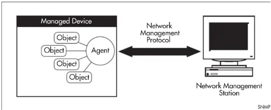
flowchart
graph LR
    A["Managed Device"] --> B["Agent"]
    B --> C["Object"]
    B --> D["Object"]
    B --> E["Object"]
    B --> F["Object"]
    C <--> G["Network Management Protocol"]
    D <--> G
    E <--> G
    F <--> G
    G --> H["Network Management Station"]
FIGURE 6-1 Components of a network management system
The Internet-standard Network Management Framework is the framework used for network management in the Internet. The framework was originally defined by the following documents:
- RFC 1155, Structure and identification of management information for TCP/IP based internets (referred to as the SMI), details the mechanisms used to describe and name the objects to be managed.
- RFC 1213, Management Information Base for network management of TCP/IP-based internets: MIB-II (referred to as MIB-II), defines the core set of managed objects for the Internet suite of protocols. The set of managed objects can be extended by adding other MIBs specific to particular protocols, interfaces or network devices.
- RFC 1157, A Simple Network Management Protocol (SNMP), is the protocol used for communication between management stations and managed devices.
Subsequent documents that have defined SNMPv2c are:
• RFC 1901, Introduction to Community-based SNMPv2
• RFC 1902, Structure of Management Information for Version 2 of the Simple Network Management Protocol (SNMPv2)
• RFC 1903, Textual Conventions for Version 2 of the Simple Network Management Protocol (SNMPv2)
• RFC 1904, Conformance Statements for Version 2 of the Simple Network Management Protocol
• RFC 1905, Protocol Operations for Version 2 of the Simple Network Management Protocol (SNMPv2)
• RFC 1906, Transport Mappings for Version 2 of the Simple Network Management Protocol (SNMPv2)
• RFC 1907, Management Information Base for Version 2 of the Simple Network Management Protocol (SNMPv2)
- RFC 2576, Coexistence between Version 1, Version 2, and Version 3 of the Internet-standard Network Management Framework
• RFC 2578, Structure of Management Information Version 2 (SMlv2)
• RFC 2579, Textual Conventions for SMIv2
• RFC 2580, Conformance Statements for SMlv2
6.4.3 Structure of Management Information
The structure of management information (SMI) defines the schema for a collection of managed objects residing in a virtual store called the management information base (MIB). The information in a MIB includes administrative and operational configuration information, as well as counters of system events and activities.
The MIB is organized into a tree-like hierarchy in which nodes are each assigned an identifier consisting of a non-negative integer and an optional brief textual description.
Each managed object is represented by a leaf node and is defined by its name, syntax, access mode, status and description. It can also be specifically identified by its unique position within the tree. This position is expressed as a series of dot-delimited sub-identifiers that start at the root node and end in the sub-identifier at the particular object's leaf node. For example, in Figure 85-2 the object named interfaces would be uniquely identified by the string of individual sub-identifiers, 1.3.6.1.2.1.2.
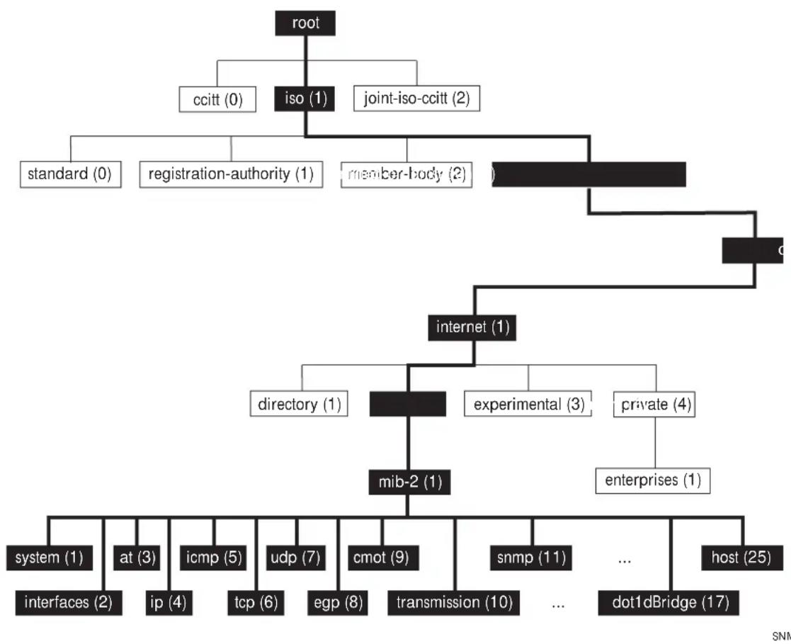
flowchart
graph TD
    A["root"] --> B["ccitt (0)"]
    A --> C["iso (1)"]
    A --> D["joint-iso-ccitt (2)"]
    C --> E["standard (0)"]
    C --> F["registration-authority (1)"]
    C --> G["member-body (2)"]
    D --> H["c"]
    H --> I["internet (1)"]
    I --> J["directory (1)"]
    I --> K["experimental (3)"]
    I --> L["private (4)"]
    K --> M["mib-2 (1)"]
    L --> N["enterprises (1)"]
    M --> O["system (1)"]
    M --> P["at (3)"]
    M --> Q["icmp (5)"]
    M --> R["udp (7)"]
    M --> S["egp (8)"]
    M --> T["cmot (9)"]
    N --> U["snmp (11)"]
    N --> V["..."]
    N --> W["dot1dBridge (17)"]
    W --> X["host (25)"]
    X --> Y["interfaces (2)"]
    X --> Z["ip (4)"]
    X --> AA["tcp (6)"]
    X --> AB["epg (8)"]
    X --> AC["transmission (10)"]
FIGURE 6-2 Top levels of the Internet-standard Management Information Base (MIB)
Objects defined in the Internet-standard MIB (MIB-II) reside in the mib(I) sub-tree.
6.4.4 Names
Names are used to identify managed objects, and are hierarchical in nature. An object identifier is a globally unique, authoritatively assigned sequence of non-negative integers which traverse the MIB tree from the root to the node containing the object.
Object identifiers may be represented in one of the following forms:
- Dotted notation lists the integer values found by traversing the tree from the root to the node in question, separated by dots. For example, the following identifies the MIB-II sub-tree:
1.3.6.1.2.1 - The following identifies the sysDescr object in the system group of MIB-II:
1.3.6.1.2.1.1.1 - Textual notation lists the textual descriptions found by traversing the tree from the root to the node in question, separated by spaces and enclosed in braces. For following example identifies the internet sub-tree:
{ iso org dod l } - The name may be abbreviated to a relative form. The following example identifies the first (directory) node of the internet sub-tree:
{internet I} - Combined notation lists both the integer values and textual descriptions found by traversing the tree from the root to the node in question. The integer value is placed in parentheses after the textual description. The labels are separated by spaces and enclosed in braces. For example, the following identifies the first (directory) node in the internet sub-tree:
{iso(1) org(3) dod(6) internet(1) 1}
• The name may be abbreviated to the following:
directory(I)
Since there is no effective limit to the magnitude of non-negative integers, and no effective limit to the depth of the tree, the MIB provides an unlimited name space.
An object is also usually assigned an object descriptor. The object descriptor is a unique, mnemonic, printable string intended for humans to use when discussing the MIB.
6.4.5 Instances
Objects are just templates for data types. An actual value that can be manipulated by an NMS is an instance of an object. An instance is named by appending an instance identifier to the end of the object's object identifier. The instance identifier depends on the object's data type:
- If the object is not a column in a table, the instance identifier is 0 (zero). For example, the instance of the sysDescr object is:
sysDescr.0
- If the object is a column in a table, the method used to assign an instance identifier varies. Typically, the value of the index column or columns is used.
The object ifTable in MIB-II contains information about interfaces and is indexed by the interface number, ifIndex. The instance of the ifDescr object for the first interface is:
ifDescr.1
If the index column is an IP address, the entire IP address is used as the instance identifier. The object ipRouteTable in MIB-II contains information about IP routes and is indexed by the destination address, ipRouteDest. The instance of the ipRouteNextHop object for the route 131.203.9.0 is:
ipRouteNextHop.131.203.9.0
If the table has more than one index, the values of all the index columns are combined to form the instance identifier. The object tcpConnTable in MIB-II contains information about existing TCP connections and is indexed by the local IP address (tcpConnLocalAddress), the local port number (tcpConnLocalPort), the remote IP address (tcpConnRemAddress) and the remote port number (tcpConnRemPort) of the TCP connection. The instance of the tcpConnState object for the connection between 131.203.8.36,23 and 131.203.9.197,1066 is:
tcpConnState.131.203.8.36.23.131.203.9.197.1066
or 1.3.6.1.2.1.6.13.1.1.131.203.8.36.23.131.203.9.197.1066
6.4.6 Syntax
The syntax of an object describes the abstract data structure corresponding to that object type. For example, INTEGER or OCTET STRING.
6.4.7 Access
The access mode of an object describes the level of access for the object.
Access modes for MIB objects are:
- Read-only The object's value can be read but not set.
- Read-write The object's value can be read and set.
- Write-only The object's value can be set but not read.
- Not-accessible The object's value cannot be read or set.
6.4.8 Status
The status of an object describes the implementation requirements for the object.
Status values for MIB objects are:
- Mandatory Managed devices must implement the object.
- Optional Managed devices may implement the object.
- Obsolete Managed devices need no longer implement the object.
- Deprecated Managed devices should implement the object. However, the object may be deleted from the next version of the MIB. A new object with equal or superior functionality is defined.
6.4.9 Description
The definition of an object may include an optional textual description of the meaning and use of the object. This description is often essential for successful understanding of the object.
6.4.10 The SNMP Protocol
The SNMP protocol provides a mechanism for management entities, or stations, to extract information from the Management Information Base (MIB) of a managed device.
The normal method of accessing information in a MIB is to use a Network Management Station (NMS), typically a PC or workstation, to send commands to the managed device (in this case the switch) using the SNMP protocol.
SNMP can use a number of different protocols as its underlying transport mechanism, but the most common transport protocol, and the only one supported by the switch, is UDP. Therefore the IP module must be enabled and properly configured in order to use SNMP. SNMP trap messages are sent to UDP port 162; all other SNMP messages are sent to UDP port 161. The switch's SNMP agent accepts SNMP messages up to the maximum UDP length the switch can receive.
Other transport mappings have been defined (e.g. OSI [RFC 1418], AppleTalk [RFC 1419] and IPX [RFC 1420]), but the standard transport mapping for the Internet (and the one the switch uses) is UDP. The IP module must be enabled and configured correctly. See Layer 3 Routing Command List for detailed descriptions of the commands required to enable and configure IP.
6.4.10.1 SNMP Versions
iMG supports SNMP version I (SNMPv1) and SNMP version 2c (SNMPv2c). The two versions operate similarly.
SNMPv2c updated the original protocol, and offered the following main enhancements:
- a new format for trap messages.
- the get-bulk-request PDU allows for the retrieval of large amounts of data, including tables, with one message.
- more error codes mean that error responses to set messages have more detail than is possible with SNMPv1.
- three new exceptions to errors can be returned for get, get-next and get-bulk-request messages. These are: noSuchObject, noSuchInstance, and endOfMibView.
SNMPv3 provides significant enhancements to address the security weaknesses existing in the earlier versions. This is achieved by implementing two new major features:
- Authentication - by using password hashing and time stamping.
- Privacy - by using message encryption.
Support for multiple versions of SNMP is achieved by responding to each SNMP request with a response of the same version. For example, if an SNMPv1 request is sent to the switch, an SNMPv1 response is returned. If an SNMPv2c request is sent, an SNMPv2c response is returned. Therefore, authentication and encryption functions are not invoked when messages are detected as having either an SNMPv1 or SNMPv2c protocol format.
6.4.10.2 SNMP Messages
The SNMP protocol is termed simple because it has only six operations, or messages—get, get-next, get-response, set, and trap, and SNMPv2c also has the get-bulk-request message. The replies from the managed device are processed by the NMS and generally used to provide a graphical representation of the state of the network. The two major SNMP operations available to a management station for interacting with a client are the get and set operations. The SNMP set operator can lead to security breaches, since SNMP is not inherently very secure. When forced to operate in either SNMPv1 or v2 mode, when operating with older management stations for example, care must be taken in the choice and safe-guarding of community names, which are effectively passwords for SNMP.
6.4.10.3 Polling versus Event Notification
SNMP employs a polling paradigm. A Network Management Station (NMS) polls the managed device for information as and when it is required, by sending get-request, get-next-request, and/or get-bulk-request PDUs to the managed device. The managed device responds by returning the requested information in a get-response PDU. The NMS may manipulate objects in the managed device by sending a set-request PDU to the managed device.
The only time that a managed device initiates an exchange of information is in the special case of a trap PDU. A managed device may generate a limited set of traps to notify the NMS of critical events that may affect the ability of the NMS to communicate with the managed device or other managed devices on the network, and therefore to “manage” the network. Such
events include the restarting or re-initialization of a device, a change in the status of a network link (up or down), or an authentication failure.
6.4.10.4 Message Format for SNMPv1 and SNMPv2c
Table 6-6: Fields in an SNMP message
| Field Function | |
| Version The version of the | SNMP protocol. The value is version-1 (0) for the SNMP protocol as defined in RFC 1157, or version-2c (1) for the SNMP protocol as defined in RFC 1902. |
| Community The name of | an SNMP community, for authentication purposes |
| SNMP PDU An SNMP Protocol Data Unit (PDU). | |
Table 6-7: SNMP PDUs
| PDU Function | |
| get-request Sent by an NMS to an agent, to retrieve the value of an object. | |
| get-next-request Sent by an NMS to an agent, to retrieve the value of the next object in the sub-tree. A sub-tree is traversed by issuing a get-request PDU followed by successive get-next-request PDUs. | |
| get-bulk-request Sent by an NMS to an agent to request a large amount of data with a single message. This is for SNMPv2c messages. | |
| set-request Sent by an NMS to an agent, to manipulate the value of an object. SNMP PDU Version Community | |
| get-response Sent by an agent to an NMS in response to a get-request, get-next-request, get-bulk-response, or set-request PDU. | |
| trap Sent by an agent to an NMS to notify the NMS of a extraordinary event. | |
| report Although not explicitly defined in the RFCs, reports are used for specific purposes such as EngineID discovery and time synchronization. | |
Table 6-8: Generic SNMP Traps
| Value Meaning | |
| coldStart | The agent is re-initializing itself. Objects may be altered. |
| warmStart | The agent is re-initializing itself. Objects are not altered. |
| linkDown | An interface has changed state from up to down. |
| linkUp | An interface has changed state from down to up. |
| authenticationFailure | An SNMP message has been received with an invalid community name. |
| egpNeighborLoss | An EGP peer has transitioned to down state. |
6.4.11 SNMP Communities (Version v1 and v2c)
A community is a relationship between an NMS and an agent. The community name is used like a password for a trivial authentication scheme. Both SNMPv1 and SNMPv2c provide security based on the community name only.
6.4.11.1 SNMPv1 and SNMPv2c
Although software levels 2.6.3 and higher support the specific facilities of SNMP v1 and v2, their documentation is available to provide backward compatibility with older network management systems. The far superior security features offered by implementing SNMPv3 should be used wherever possible.
The switch's implementation of SNMPv1 is based on RFC 1157, A Simple Network Management Protocol (SNMP), and RFC 1812, Requirements for IP Version 4 Routers.
When the SNMP agent is disabled, the agent does not respond to SNMP request messages. The agent is disabled by default. The current state and configuration of the SNMP agent can be displayed.
6.4.11.2 SNMP MIB Views for SNMPv1 and SNMPv2c
An SNMP MIB view is a arbitrary subset of objects in the MIB. Objects in the view may be from any part of the object name space, and not necessarily the same sub-tree. An SNMP community profile is the pairing of an SNMP access mode (read-only or read-write) with the access mode defined by the MIB for each object in the view. For each object in the view, the community profile defines the operations that can be performed on the object.
Pairing an SNMP community with an SNMP community profile determines the level of access that the agent affords to an NMS that is a member of the specified community. When an agent receives an SNMP message, it checks the community name encoded in the message. If the agent knows the community name, the message is deemed to be authentic and the sending SNMP entity is accepted as a member of the community. The community profile associated with the community name then determines the sender's view of the MIB and the operations that can be performed on objects in the view.
6.4.11.3 SNMP Communities
SNMP communities were introduced into SNMPv1 and retained in version 2c. Although the switch's software still supports communities, this is to provide backward compatibility with legacy management systems. Communities should not be used where a secure network is required. Instead, use the secure network features offered by SNMPv3.
An SNMP community is a pairing of an SNMP agent with a set of SNMP application entities. Communities are the main configuration item in the switch's implementation of SNMPv1 and v2, and are defined in terms of a list of IP addresses which define the SNMP application entities (trap hosts and management stations) in the community.
Important community names act as passwords and provide minimal authentication. Any SNMP application entity that knows a community name can read the value of any instance of any object in the MIB implemented in the switch. Any SNMP application entity that knows the name of a community with write access can change the value of any instance of any object in the MIB implemented in the switch, possibly affecting the operation of the switch. For this reason, take care with the security of community names.
When a trap is generated by the SNMP agent it is forwarded to all trap hosts in all communities. The community name and manager addresses are used to provide trivial authentication. An incoming SNMP message is deemed authentic if it contains a valid community name and originated from an IP address defined as a management station for that community.
When a community is disabled, the SNMP agent behaves as if the community does not exist and generates authentication failure traps for messages directed to the disabled community.
The SNMP agent does not support a default community called “public” with read-only access, traps disabled and open access as mandated in RFC 1812, as this is a security hole open for users who wish to use the switch with minimal modification to the default configuration. The default configuration of the switch has no defined communities. Communities must be explicitly created.
SNMP authentication (for SNMPv1 and v2) is a mechanism whereby an SNMP message is declared to be authentic, that is from an SNMP application entity actually in the community to which the message purports to belong. The mechanism may be trivial or secure. The only form of SNMP authentication implemented by the switch's SNMP agent is trivial authentication. The authentication failure trap may be generated as a result of the failure to authentication an SNMP message.
Switch interfaces can be enabled or disabled via SNMP by setting the ifAdminStatus object in the ifTable of MIB-II MIB to 'Up(1)' or 'Down(2)' for the corresponding ifIndex. If it is not possible to change the status of a particular interface the switch returns an SNMP error message.
The switch's implementation of the ifOperStatus object in the ifTable of MIB-II MIB supports two additional values—"Unknown(4)" and "Dormant(5)" (e.g. an inactive dial-on-demand interface).
Caution: An unauthorized person with knowledge of the appropriate SNMP community name could bring an interface up or down. Community names act as passwords for the SNMP protocol. When creating an SNMP community with write access, take care to select a secure community name and to ensure that only authorized personnel know it.
An SNMP MIB view is a subset of objects in the MIB that pertain to a particular network element. For example, the MIB view of a hub would be the objects relevant to management of the hub, and would not include IP routing table objects, for example. The switch's SNMP agent does not allow the construction of MIB views. The switch supports all relevant objects from all MIBs that it implements.
Note that the switch's standard set and show commands can also be used to access objects in the MIBs supported by the switch.
6.4.11.4 Defining Management Stations within Communities
You can add management stations to a community either individually, by entering just its IP address, or you can enter a range of management stations by entering an IP address that ends with a '/' character followed by a number between 1 and 32. The number that follows the '/' character operates as an address mask to define a range of addresses for the management stations. The following example shows how to allocate a band of three binary addresses to a portion of the subnet 146.15.1.X
In this example we make provision for up to 8 possible management stations within a community called “admin”.
6.4.12 Configuration Example (SNMPv1 and v2)
This example shows how to configure the switch's SNMP agent. Two network management stations have been set up on a large network. The central NMS (IP address 192.168.11.5) monitors devices on the network and uses SNMP set messages to manage devices on the network. Trap messages are sent to this management station. The regional network management station (IP addresses 192.168.16.1) is used just to monitor devices on the network by using SNMP get messages. Link traps are enabled for all interfaces on this particular switch.
IP and VLANs must be correctly configured in order to access the SNMP agent in the switch. This is because the IP module handles both the TCP transport functions, and the UDP functions that enable datagrams to transport SNMP messages.
To configure SNMP
1. Enable the SNMP agent.
Enable the SNMP agent and enable the generation of authenticate failure traps to monitor unauthorized SNMP access. SNMP is enabled by default in AlliedWare Plus.
awplus(config)# snmp-server
Note: Battery traps require the power-management feature to be enabled.
6.4.13 Object ID (OID) Numbers for iMG Models
6.4.14 The following OIDs are registered for the iMG Models.SNMP Command List
Table 6-9: OID Registration Numbers
| Model OID | |
| iMG1505 1.3.6.1.4.1.207.1.17.101 | |
| iMG1525 1.3.6.1.4.1.207.1.17.89 | |
| iMG1525RF 1.3.6.1.4.1.207.1.17.91 | |
| iMG2504 1.3.6.1.4.1.207.1.17.108 | |
| iMG2522 1.3.6.1.4.1.207.1.17.110 | |
| iMG2524 1.3.6.1.4.1.207.1.17.93 | |
| iMG2524H 1.3.6.1.4.1.207.1.17.95 | |
| iMG2524F 1.3.6.1.4.1.207.1.17.109 | |
| iMG1405 1.3.6.1.4.1.207.1.17.111 | |
| iMG1405W 1.3.6.1.4.1.207.1.17.126 | |
| iMG1425 1.3.6.1.4.1.207.1.17.112 | |
| iMG1425W 1.3.6.1.4.1.207.1.17.113 | |
| iMG12426F 1.3.6.1.4.1.207.1.17.125 | |
This provides an alphabetical reference for commands used to configure SNMP.
For information about modifying or redirecting the output from show commands to a file, see Controlling "show" Command Output.
Table 6-10: SNMP Command List
| show running-config snmp |
| show snmp-server |
| show snmp-server community |
| show snmp-server traps |
| snmp-server ip |
| snmp-server community |
| snmp-server contact |
| snmp-server enable traps link-status |
| snmp-server host |
| snmp-server location |
| snmp-server system-shutdown |
SHOW RUNNING-CONFIG SNMP
Syntax show running-config snmp
Description This command displays the current configuration of SNMP on your device.
Feature SNMP Commands
Mode Privileged Exec Mode
Release 4.2
Options NA
Note NA
Example To display the current configuration of SNMP on your device, use the command:
awplus# show running-config snmp
snmp-server host 212.58.224.138
snmp-server location Milan
snmp-server contact info@alliedtelesis.com
snmp-server community public ro
snmp-server community private rw
snmp-server ip
SHOW SNMP-SERVER
Syntax show snmp-server
Description This command displays the status and current configuration of the SNMP server.
Feature SNMP Commands
Mode Privileged Exec Mode
Release 4.2
Options NA
Note NA
Example To display the status of the SNMP server, use the command:
awplus# show snmp-server
SNMP Server Enabled
IP Protocol IPv4
System Shutdown Enabled
SHOW SNMP-SERVER COMMUNITY
Syntax
show snmp-server community
Description
This command displays the SNMP server communities configured on the device. SNMP communities are specific to v1 and v2c.
Feature SNMP Commands
Mode Privileged Exec Mode
Release 4.2
Options NA
Note NA
Example To display the status of the SNMP server, use the command:
awplus# show snmp-server community
SNMP community information:
Community Name private
Access Read-write
Community Name public
Access Read-only
SHOW SNMP-SERVER TRAPS
Syntax
show snmp-server traps
Description
This command displays the current configuration of SNMP server traps.
Feature SNMP Commands
Mode Privileged Exec Mode
Release 4.4
Options NA
Note NA
Example To display the current configuration of SNMP on your device, use the command:
awplus# show snmp-server traps
SNMP traps information:
Link-Status Traps ..... Enabled
Network Management Simple Network Management Protocol (SNMP)
SNMP-SERVER IP
Syntax
snmp-server ip no snmp-server ip
Description
This command enables the SNMP agent (server) on the switch. The SNMP agent receives and processes SNMP packets sent to the switch, and generates notifications (traps) that have been enabled by the snmp-server enable trap command on page 86.18.
Use the no variant of this command to disable the SNMP agent on the switch. When SNMP is disabled, SNMP packets received by the switch are discarded, and no notifications are generated. This does not remove any existing SNMP configuration.
By default, the SNMP agent is enabled for IPv4 (IPv6 is not supported.)
Feature SNMP Commands
Mode Global Configuration Mode
Release 4.2
Options NA
Note NA
Example To enable the SNMP agent for IPv4 on the device, use the commands: awplus(config)# snmp-server ip
Example To disable the SNMP agent for IPv4 on the switch, use the commands: awplus(config)# no snmp-server ip
SNMP-SERVER COMMUNITY
Syntax
snmp-server community
no snmp-server community
Description
This command creates an SNMP community, optionally setting the access mode for the community. The default access mode is read only. If view is not specified, the community allows access to all the MIB objects. The SNMP communities are only valid for SNMPv1 and v2c and provide very limited security. Communities should not be used when operating SNMPv3.
The no variant of this command removes an SNMP community. The specified community must already exist on the device.
Feature SNMP Commands
Mode Global Configuration Mode
Release 4.2
Options
| Option Description Range | Default Value | ||
| Community name. The community name is a string up to 20 characters long and is case sensitive. | NA NA | ||
| read/write Controls whether the community is Read only (ro) or Read Write (rw] | NA NA | ||
Note NA
Example The following command creates an SNMP community called "public" with read only access to all MIB variables from any management station
awplus(config)# snmp-server community public ro
Example The following command removes an SNMP community called "public":
awplus(config)# no snmp-server community public
SNMP-SERVER CONTACT
Syntax
snmp-server contact
no snmp-server contact
Description
This command sets the contact details of the system. The contact details are
- displayed in the output of the show system command
- stored in the MIB object sysContact
Use the no variant of this command to remove the configured contact details from the system.
Feature SNMP Commands
Mode Global Configuration Mode
Release 4.2
Options
| Option Description Range | Default Value | ||
| The contact details of the system, from 1 to 32 characters long. Valid characters are any printable character and spaces. | NA NA | ||
Note NA
Example To set the contact details to "info@alliedtelesis.com", use the following commands:
awplus(config)# snmp-server contact info@alliedtelesis.com
SNMP-SERVER ENABLE TRAPS LINK-STATUS
Syntax
snmp-server enable traps link-status no snmp-server enable traps link-status
This command enables the SNMP traps link status. A trap of link up is sent when a cable is plugged on port1.0.1-port1.0.5 or hpna1.0.1. A trap of link down is sent when a cable is unplugged on port1.0.1-port1.0.5 or hpna1.0.1..
Feature SNMP Commands
Mode Global Configuration Mode
Release 4.4
Options NA
Note NA
Example To enable the SNMP traps link-status, use the commands:
awplus(config)# snmp-server enable traps link-status
Example To disable the SNMP traps link-status, use the commands:
awplus(config)# no snmp-server enable traps link-status
SNMP-SERVER HOST
Syntax
snmp-server host {
no snmp-server host
Description
This command specifies an SNMP trap host destination to which Trap messages generated by the device are sent.
Use the no variant of this command to remove the SNMP trap host. The trap host must already exist.
The trap host is uniquely identified by:
- host IP address (IPv4),
Feature SNMP Commands
Mode Global Configuration Mode
Release 4.2
Options
| Option Description Range | Default Value | ||
| host Configure SNMP trap host. NA NA | |||
| no Remove the specified SNMP trap host. NA NA | |||
| IPv4 trap host address in the format A.B.C.D, for example, 192.0.2.2. | NA NA | ||
Note NA
Example To configure the device to send generated traps to the IPv4 host destination 192.0.2., use the following command:
awplus(config)# snmp-server host 192.0.2.5
Example To remove a configured trap host, use the following command:
awplus(config)# no snmp-server host
SNMP-SERVER LOCATION
Syntax
snmp-server location
no snmp-server location
Description This command sets the location of the system. The location is:
- displayed in the output of the show system command
- stored in the MIB object sysLocation
The no variant of this command removes the configured location from the system.
Feature SNMP Commands
Mode Global Configuration Mode
Release 4.2
Options
| Option Description Range | Default Value | ||
| The location of the system, from 1 to 32 characters long. Valid characters are any printable character and spaces. | NA NA | ||
Note NA
Example To set the location to "server room 523", use the following commands: awplus(config)# snmp-server location server room 523
SNMP-SERVER SYSTEM-SHUTDOWN
Syntax
snmp-server system-shutdown no snmp-server system-shutdown
Description
This command enables a remote provisioning system to restart the CPE by setting the private SNMP object sysRestart. By default this object is protected and any attempt to force its value is refused. Due to the insecure level of SNMP v1/v2C it is strongly recommended to do not enable this feature unless strictly required by the management framework. In this case it's recommended to use access-list to control and protect access to SNMP objects.
Feature SNMP Commands
Mode Global Configuration Mode
Release 4.3.3
Note NA
Example Enable sysRestart SNMP object: awplus(config)# snmp-server system-shutdown
6.5 TR69 Configuration
6.5.1 Introduction
The iMG supports the following Broadband Forum data models:
- TR-098
- TR-104
The following TR-69 RPC methods are also supported:
- GetRPCMethods
- SetParameterValues
- GetParameterValues
- GetParameterNames
- GetParameterAttributes
- SetParameterAttributes
- AddObject
- DeleteObject
- Reboot
- Download
- Upload
- GetQueuedTransfers
- ScheduleInform
- FactoryReset
There are several ways to set up the iMG as a tr69 client to communicate with the Auto-Configuration Server (ACS).
- AlliedView NMS - the iMG Boot Configurator Refer to the AlliedView NMS Administration Guide.
• iMG GUI - Refer to Using the GUI Application.
- Commands - This is covered in this section.
6.5.2 TR69 Command List
This provides an alphabetical reference for commands used to configure SNMP.
For information about modifying or redirecting the output from show commands to a file, see Controlling "show" Command Output.
Table 6-11: TR69 Command List
| show tr69-client |
| tr69-client acs-authentication |
| tr69-client acs-url |
| tr69-client bind source-interface |
| tr69-client inform |
| tr69-client request-authentication |
SHOW TR69-CLIENT
Syntax show tr69-client
Description This command shows the configuration of the iMG TR69 client
Feature TR69 Commands
Mode Privileged Exec Mode
Release 4.2
Options NA
Note Passwords are deliberately obscured.
Example See the example output below:
awplus# show tr69-client
TR69 Client Configuration
Periodic Inform : Enabled
Periodic Inform Interval (seconds): 300
ACS URL : http://10.17.90.63:9797/cwmp/ACS
ACS User Name : manager
ACS Password : ****
Source Interface : vlan203
Connection Request Authentication : Disabled
Connection Request User Name :
Connection Request Password :
TR69-CLIENT ACS-AUTHENTICATION
Syntax tr69-client acs-authentication {password
Description This command configures the username and password used to authenticate the iMG when making a connection to an ACS.
Use the no variant of this command to remove configured username and password
Feature TR69 Commands
Mode Global Configuration Mode
Release 4.2
Options
| Option Description Range | Default Value | ||
| .A string of up to 256 characters. May not include white-space. | NA NA | ||
| A string of up to 256 characters. May not include white-space. | NA NA | ||
Note Used only for HTTP-based authentication of the iMG.
Example See the example output below
awplus(config)# tr69-client acs-authentication username Bilbo_Baggins awplus(config)# tr69-client acs-authentication password secret_hobbit
TR69-CLIENT ACS-URL
Syntax tr69-client acs-url
Description This command provides the URL that the iMG will use in order to connect with an ACS. Use the no variant of this command to remove a previously configured ACS URL.
Feature TR69 Commands
Mode Global Configuration Mode
Release 4.2
Options
| Option Description Range | Default Value | |
| A string of up to 256 characters. This parameter must be in the form of a valid HTTP or HTTPS URL. | NA NA |
Note
Example See the example output below
awplus(config)# tr69-client acs-url http://10.17.90.52:9797/ACS
TR69-CLIENT BIND SOURCE-INTERFACE
Syntax
tr69-client bind source-interface
Description
This command manually associates the tr69 client to the interface (VLAN) that will be used by the tr69 client to communicate with the ACS. This is useful since the TR69 client will bind to the first available Interface that has a status of connected, and will send messages on that interface, which may not be the preferred route to the ACS.
Use the no variant of this command to remove the associated Interface.
Feature TR69 Commands
Mode Global Configuration Mode
Release 4.2
Options
| Option Description | Default Value |
Note
If the iMG is configured using DHCP (option 43), the VLAN receiving option 43 will be set as the VLAN for communication with the ACS.
Example See the example output below
awplus(config)# tr69-client bind source-interface vlan202
TR69-CLIENT BIND SOURCE-INTERFACE
Syntax
tr69-client bind source-interface
Description
This command binds ACS signaling to a specific interface "VLAN id". Use the no variant of this command to set a default value "Any_WAN".
Feature TR69 Commands
Mode Global Configuration Mode
Release 4.2
Options
| Option Description Range | Default Value | |
| The VLAN that is used to bind the ACS singaling with. vlan1-vlan4094Any_WAN | vlan4094 | Any_WAN |
Note NA
Example See the example output below
awplus(config)# tr69-client bind source-interface vlan203
TR69-CLIENT INFORM
Syntax tr69-client inform {interval
Description This command configures the interval at which the iMG will invoke the TR69 inform method to send iMG information to the ACS. This command is also used enable the sending of periodic informs.
Use the no variant of this command to disable the sending of periodic informs.
Feature TR69 Commands
Mode Global Configuration Mode
Release 4.2
Options
| Option Description Range | Default Value | |
| An integer value in the range 1 - 4294967295 seconds. 1- | 4294967295 | 300 |
Note NA
Example See the example output below
awplus(config)# tr69-client inform interval 500
awplus(config)# tr69-client inform
awplus(config)# no tr69-client inform
TR69-CLIENT REQUEST-AUTHENTICATION
Syntax tr69-client request-authentication {password
Description This command configures the username and password used to authenticate an ACS when an incoming connection request is received by the iMG.
Use the no variant of this command to remove configured username and password
Feature TR69 Commands
Mode Global Configuration Mode
Release 4.2
Options
| Option Description Range | Default Value | ||
| A string of up to 256 characters. May not include white-space | NA NA | ||
| A string of up to 256 characters. May not include white-space | NA NA |
Note NA
Example See the example output below
awplus(config)# tr69-client request-authentication username Saruman awplus(config)# tr69-client request-authentication password good_istari
6.5.3 Universal Plug and Play
6.5.3.1 Introduction
Universal Plug and Play (UPnP) is a networking protocol that permits devices, such as the iMG, to discover the presence of other devices on the network and establish functional network services for data sharing, communications, and entertainment. The iMG supports version 1.0 of the UPnP Device Architecture (http://upnp.org/specs/arch/UPnP-arch-DeviceArchitecture-v1.0.pdf).
6.5.3.2 UPnP on the iMG
The primary use for UPnP on the iMG is to allow the iMG to utilize the UPnP implementation of a NAT traversal protocol called Internet Gateway Device (IGD). A device that supports this combined UPnP/IGD protocol can reveal itself as an Internet Gateway Device. This opening can allow a local UPnP control point to perform a set of actions including:
• Retrieve the external IP address of the device
- Enumerate existing port mappings
- Add port mappings
- Remove port mappings
For example, by adding a port mapping, a UPnP controller behind the IGD can enable traversal of the IGD from an external address to an internal client.
6.5.3.3 UPnP Command List
This section provides an alphabetical reference of configure, clear, and show commands related to UPnP.
Table 6-12: UPnP Command List
| ip upnp local enable |
| ip upnp network enable |
| show ip upnp |
Description This command activates UPnP on the interface.
Feature UPnP Commands
Mode Global Configuration Mode
Release 4.3.1
Options NA
Note NA
Example See the following commands for options to enable UPnP on the local interface, in this case VLAN 100:
interface vlan100
ip upnp local enable
Example To disable UPnP on VLAN 100, use the following commands:
interface vlan100
no ip upnp local enable
IP UPNP NETWORK ENABLE
Syntax
ip upnp network enable
no ip upnp network enable
Description This command activates UPnP on the network interface.
Feature UPnP Commands
Mode Global Configuration Mode
Release 4.3.1
Options NA
Note NA
Example See the following commands for options to enable UPnP on the network interface, in this case VLAN 200:
interface vlan200
ip upnp network enable
Example To disable UPnP on VLAN 200, use the following commands:
interface vlan200
no ip upnp network enable
SHOW IP UPNP
Syntax
ip upnp network enable
no ip upnp network enable
Description This command displays information regarding UPnP.
Feature UPnP Commands
Mode Global Configuration Mode
Release 4.3.1
Options NA
Note NA
Example
awplus# show ip upnp
UPnP summary
Enabled : yes
Status : active
Network interface : vlan200
Local interface : vlan100
awplus#
Example
awplus# show ip upnp
UPnP summary
Enabled : no
Status : inactive
Network interface : n/a
Local interface : n/a
awplus#
7. Voice Management
The Voice Management functions of the Allied Telesis Gateway Product Family devices include the following:
• Voice Service and Protocols
• Voice Service Command List (config-voi-serv)
- Enable/Disable MGCP Command List (config-serv-mgcp)
- Enable/Disable SIP Command List (config-serv-sip)
- Configure MGCP Protocol Command List (config-mgcp)
- Configure SIP Protocol Command List (config-sip-ua)
- Configuring Voice Applications on Device and Ports
- Access Codes (Supplementary Services) Command list (config-voipapp-fac)
• Supplementary Service Command list (voipapp-suppl-serv-port)
• Endpoint Command List (config-voice-port)
- Configuring Codecs Command List
- Configuring Dial Peers
- Configuring Dial Peers Command List (config-dial-peer)
7.1 Voice Service and Protocols
7.1.1 Introduction
Telephone service uses Voice Over Internet Protocol technology (VOIP). VOIP involves two components:
• The signaling protocol that manages the phone conversation
• The media protocol that encodes / encapsulates the audio information.
The Allied Telesis Gateway Product Family devices (referred to for the rest of this sections as the iMG) support media transmission through various audio codecs which are encapsulated in Real Time Protocol (RTP) packets. It supports two signaling protocols which are the following: Media Gateway Control Protocol (MGCP) and Session Initiation Protocol (SIP). During operation only one protocol can be active, however switching between protocols is possible with relative ease.
Configuration of the voice system can be achieved through two mechanisms. The first configuration path is through the use of an Automated Configuration Server (ACS) utilizing the TR-069 and TR-104 specifications. Refer to Section I. Configuring voice service using the CLI is described in this section.
7.1.2 MGCP
The Media Gateway Control Protocol (MGCP) relies on a master / slave methodology. The Media Gateway Controller (MGC) is an "intelligent" central point where all call control decisions are made. In this architecture, the iMG plays the role of the Media Gateway (MG) and is responsible for carrying out any instructions that are given to it by the central server.
There are many different ways in which the iMG can be used in a MGCP environment. The two general forms of operation are an "out-of-band" configuration or a Network Controlled Signaling (NCS) configuration. The "out-of-band" mode of oper-
ation relies on the MGCP protocol to transmit information between the MGC and the MG. This would include events originating from the CPE (user events such as digits, hook changes) and information being sent to the device from the server (signal requests, media configuration). The details of the MGCP protocol are described in RFC3435. The NCS configuration utilizes the media stream itself to carry information between the server and the client (or between the two endpoints directly). Events and signals are encoded in the Real Time Protocol (RTP) using the mechanisms described in RFC4733
7.1.2.1 MGCP Endpoints
Allied Telesis Gateway Product Family devices support the configuration of each FXS (Foreign Exchange Station) voice port as a separate MGCP analogue endpoint allowing a different level of services (number of phone lines) to be delivered.
Each voice port is identified univocal through an endpoint identifier that, by default, takes the following syntax:
aaln/<slot>@[$IP]
where:
- AALN -Analog Access Line endpoint. This name indicates that the endpoint is analog type (only FXS voice interfaces are supported).
- indicates the index of the voice port. Physical voice ports start with index 0, the second physical voice port uses index 1 and so on. The starting number can be specified to be 1 rather than 0. - \$IP - it's the ip address of the ip interface where the MGCP protocol is enabled. It is typically used in a multi host configuration where more than one IP interface is configured in the system or when the ip interface is dynamic and therefore the value is dynamically assigned by the network.
Analog endpoint MGCP identifiers can be customized to meet VoIP network configuration requirements.
The syntax of the local name of each endpoint identifier is in the format:
aaln/<slot>
where
aaln/0
aaln/1
The syntax of the local name can be changed forcing the index of the POTS interfaces to start from 1 instead from 0 (i.e. aaln/1 and aaln/2):
awplus(config-mgcp)# endpoint offset
The syntax of the domain name component of each endpoint identifier can be set to any string and can use also special keywords identified by the "\$" sign that are automatically replaced by the value of the attribute that they represent.
The following two special keywords are supported:
- \$IP - when used, this keyword is automatically replaced by the ip address value (in IPv4 dotted format) of the ip interface where MGCP protocol has been enabled.
- \$MAC - when used, this keyword is automatically replaced by the MAC address of the Allied Telesis Gateway Product Family device.
- \$HOST – when used, this keyword is automatically replaced by the hostname of the Allied Telesis Gateway Product Family device.
It is therefore possible create complex endpoint identifiers like the following:
- aaln/0@[\$IP] that will be translated at runtime for example in: aaln/0@[172.30.1.1]
- aaln/0@\$IP that will be translated at runtime for example in: aaln/0@172.30.1.1
- aaln/0@\$MAC that will be translated at runtime for example in: aaln/0@00:0d:da:01:fe:ac
- aaln/0@any-string-here
To specify a new endpoint syntax for an existing voice port the following command is used:
Awplus(config-mgcp)# domain
Note: By default each endpoint is disabled. To enable the endpoint (i.e. to register each endpoint to the Call Agent) use the following command:
awplus(config-voiceport)# no shutdown
7.1.2.2 MGCP Wildcard
Wildcard is a method to reduce the amount of MGCP signaling traffic generated during the registration phase.
In this case the User Agent notifies to the Call Agent only one RSIP message (instead of two) to request the registration of both of the two endpoints.
Wildcard support is also needed for interoperability with some Call Agents that use wildcard in their Audit Endpoint requests.
To enable the wildcard support (by default it is disabled), the following command is used:
awplus(config-mgcp)# behavior rsip-range all
7.1.2.3 MGCP Heartbeat
The Allied Telesis Gateway Product Family supports the heartbeat mechanism to detect whether User Agents are still active. Each Allied Telesis Gateway Product Family voice port has a unique User Agent permanently associated to it. Heartbeat mechanism is typically requested on deployments that use Network Address Translation (NAT). The reason for this requirement is that if a NAT binding expires, there is no way for a Call Agent to send an incoming call to the User Agent as NAT bindings are generated via outgoing UDP packets. Using a heartbeat mechanism allows the User Agent to detect loss of the NAT binding (due for example to DSL uplink fails) and recreate it if required. The heartbeat mechanism is implemented through the use of Audit commands as AuditConnection and AuditEndpoint.
The Allied Telesis Gateway Product Family endpoints support a configurable messaging mechanism and a configurable heartbeat timer. The endpoint waits for either the expiration of this timer, the reception of a command for the endpoint from the Call Agent, or the detection of a local user activity for the endpoint, such as for example an off-hook transition.
If the heartbeat timer expires the User Agent enters the “disconnected” procedure. The User Agents run a further disconnect timer and if they do not receive a command from the Call Agent or detect local activity before the timer expires, the endpoint sends an RSIP disconnected command to the Call Agent. If it does not receive a response it continues to periodically retry to contact the provisioned Call Agents. If the Call Agent is using the above heartbeat mechanism, the heartbeat timer should be set to a value that allows the Call Agent to send an audit command sufficiently often that the User Agent will see at least 3 audit commands in the heartbeat time interval. This is to prevent a single packet loss causing the User Agent to become “disconnected”.
By default heartbeat is disabled and can be enabled via the following command:
Awplus(config-mgcp)# behavior heartbeat RSIP-refresh 10
When heartbeat is enabled, each endpoint (or User Agent) supervises the operative status of Call Agent independently of the status of the other endpoints.
It is possible to force a specific endpoint to check for Call Agent activity and to be master also for the other endpoints. If the specific endpoint does not receive a command from the Call Agent within the heartbeat timer time-out it forces all the User Agents to enter into the disconnected procedure.
To activate this behavior it's necessary to enable the heartbeat and specify also the master endpoint entering the following command:
awplus(config-mgcp)# behavior heartbeat RSIP-refresh 10 master tel2
If no commands are received from the Call Agent within the timeframe specified by the heartbeat refresh time, the User Agents starts to notify to the Call Agent an heartbeat message.
The type of MGCP message notified to the User Agent and used for the heartbeat can be selected between:
- NTFY L/hb
- RSIP Keepalive
- RSIP Refresh
The retransmission of heartbeat messages form the User Agent follows the same rules as for the transmission of any message sent by the User Agent.
The User Agent will attempt to send a maximum of "Request retries" messages for period of time no longer than "Request timeout" before entering into the disconnect procedure.
7.1.2.4 MGCP Call Agent Failover
The Allied Telesis Gateway Product Family supports dual Call Agents failover mechanism to switch between inactive to active call agents in order to support high availability services. The failover mechanism is triggered any time a request sent by the User Agents does not get any answer from the Call Agent within the round-trip time-out.
In this case if more than one call agent is configured, the User Agent will re-send the same command toward the second call agent. As soon the User Agent get an answer from the second call agent, the second call agent becomes the active call agent and will be used for all the subsequent requests.
The process repeats any time a call agent is not reachable switching in this way the communications between primary call agent to secondary call agent and vice versa.
To set the primary call agent use the following command:
awplus(config-mgcp)# call-agent <ip-address>
To specify the secondary call agent use the following command:
awplus(config-mgcp)# backup-call-agent <ip-address>
If the user Agent has sent a message but the Call Agent is not available (and the Backup Call Agent is not available too) the retransmission procedure takes place.
The User Agent will attempt to send the same MGCP message for a number of times defined by the ""Request retries" attribute and for a period of time not longer that the timeout specified by the "Request timeout" attribute.
If no answers are received, then the endpoint goes in disconnected status and RSIP-restart messages are sent until the registration is acknowledged.
The following commands are used to change the number of retries and the timeout duration:
awplus(config-mgcp)# request retries <number-of-retries>
awplus(config-mgcp)# request timeout <seconds>
7.1.3 SIP
7.1.3.1 Introduction
The Session Initiation Protocol (SIP) implements a more flexible control methodology. This flexibility gives SIP the ability to be utilized in many different network architectures. Example models are given below:
- Master / Slave Signaling
This architecture follows the same model as MGCP. A central server is responsible for making all decisions and the protocol is used to notify the end devices what of what operations to perform. This system is used often in architectures that need to be strictly administered by a central authority.
2. Direct Signaling
SIP has the ability to communicate directly with any other device that implements the protocol. This includes another iMG or any other SIP Soft Phone product that may have access to the IP network. In this configuration, no server is required to provide signaling because the endpoints distribute the decision making responsibilities between them. A forwarding database is required on each endpoint so that requests can be directed to their proper proxy, gateway system or remote SIP endpoint device. This type of signaling may be done on a smaller network where administration is less complex and the number of devices is small.
3. Registration / Proxy Signaling
This architecture is a hybrid of the above two models. Each endpoint is required to register with a central agent called the Registrar. The purpose of this system is to provide directory service for every device on the network. When a call is initiated, the location of the destination device is determined. The server then has the option of notifying the originator of the destination's location, or it can act on behalf of the originator and complete the call
7.1.3.2 SIP Digit Map
The Digit Map is a rule used by the access port to understand when dialing is to be considered completed and the dialed number is ready to be processed by the call control layer. It works for outgoing calls (in the direction from user to VoIP network). A digit map is defined either by a (case insensitive) string or by a list of strings.
Each string in the list is an alternative numbering scheme, specified either as a set of digits or timers, or as an expression over which the port will attempt to find a shortest possible match. The following constructs can be used in each digit map:
- DTMF - A digit from '0' to '9' or one of the symbols 'A', 'B', 'C', 'D'. Symbols '#' or '*', if necessary, have to be added separately.
- Timer - The symbol 'T' matching the timer expiry. The symbol 'T' at the end of Digit Map indicates that if user has not dialed a digit for a time longer than the value of the inter-digit time, the dialled number shall be considered complete. If the symbol T appears in the middle of digit map expression is not considered and skipped during expression evaluation.
- Wildcard - The symbol 'x', which matches any digit ('0' to '9').
- Range - One or more DTMF symbols enclosed between square brackets ('[' and ']).
- Subrange - Two digits separated by a hyphen (' -') that matches any digit between and including the two. The subrange construct can only be used inside a range construct, i.e., between [' and '].
- Position - A period (‘:’), which matches an arbitrary number, including zero, of occurrences of the preceding construct.
Note: The digit map, when fully expressed, shall not exceed 255 characters. Also, for call processing for SIP, the digit map is entered by the CLI or the NMS/ACS. For MGCP, it is sent to the iMG from the callagent using the MGCP messaging.
Let's consider an example where the user in an office wants to call a co-worker's 3-digit extension. The Digit Map is defined in such a way that the called number is processed after the user has entered 3 digits.
The command to set the Digit Map could look as follows:
Awplus(config-Dial-peer)# destination-pattern xxx
Note: Dial Peer 3 is the one that is used for routing calls – and thus the one that must be modified to achieve everything below.
This Digit Map specifies that after the user has entered any three digits, the call is placed. It's possible to refine this Digit Map by including a range of digits. For example, if all extensions in the user company begin with 2, 3, or 4, the corresponding Digit Map command could look as:
Voice Management Voice Service and Protocols
Awplus(config-Dial-peer)#destination-pattern [2-4]xx
If the number dialed begins with anything other than 2, 3, or 4, the call is rejected and a busy tone is generated.
Another way to achieve the same result would be:
Awplus(config-Dial-peer)#destination-pattern [234]xx
It is possible to combine two or more expressions in the same Digit Map by using the 'I' operator, which is equivalent to OR. The left-most expression has precedence over the other expressions.
Let's consider the case of a choice: the Digit Map must check if the number is internal (an extension), or external (a local call). Assuming that dialling '9' makes an external call, the Digit Map could be defined with the command:
Awplus(config-Dial-peer)# destination-pattern ([2-4]xx|9[2-9]xxxxxx)
In this case the Digit Map checks if the number begins with 2, 3, or 4 and the number has 3 digits. If not, it checks if the number begins with 9 and the second digit is any digit between 2 and 9 and the number has 7 digits
It may sometimes be required that users dial the “#” or “*” to make calls. This can be easily incorporated in a Digit Map with the command:
Awplus(config-Dial-peer)# destination-pattern xxxxxxxx# | xxxxxxxx*
The '#' or '*' character could indicate that users must dial the '#' or '*' character at the end of their number to indicate it is complete. When the outgoing call is in process, the call control layer removes any '#', '*' and 'T' symbols from the dialed number.
7.1.3.3 SIP Proxy and SIP Registrar (with Failover)
It is possible to specify different servers addresses for SIP Registrar and SIP Proxy.
SIP Registrar is used only for registration purposes.
Note: If no registrar is specified, the proxy server values will be used, and the iMG will attempt to register at the address of the SIP Proxy server.
SIP Proxy address must always be configured in order to have SIP signaling working properly during outgoing and incoming calls.
To configure SIP Registrar address use the following command:
awplus(config-sip-ua)# registrar
To configure SIP Proxy address use the following command:
awplus(config-sip-ua)# sip-server
It's also possible to specify the sip domain associated to each local dial-peer and used in the registration messages by the following command:
awplus(config-serv-sip)# localhost dns
For the Failover feature, it is possible to specify a secondary server for both Proxy and Registrar.
Note: You must always configure the Primary Proxy server (you cannot configure only the Secondary).
The rules for Proxy failover are as follows:
- The INVITE message is sent by the user agent four times. If there is no response, the user agent declares a failover and tries with the Secondary.
- If the four attempts on the Secondary fail, the user agent switches back to the Primary
Note: If Proxy servers are used for registration, it uses the same registration procedure but uses the proxy server list instead.
The rules for Registrar failover are as follows:
- The user agent will attempt registration for 28 seconds.
- If no response, restart registration is started on the Secondary with a delay of 20 seconds.
- If the secondary doesn't respond, the user agent returns to the Primary and tries again
- A successful registration marks a server as "active" and initiates are-registration on all endpoints
Note: Subsequent restarts will use the last known good registration agent.
7.1.4 Services (Common)
7.1.4.1 Dial Peers
Dial peers are used to control call routing. There are two different types of dial-peers supported:
The pots dial-peer is used to define the characteristics of the phone interface. For MGCP – this is essentially just the fact that the protocol is associated with this port; while for SIP – it includes the local address of the user that is associated with the port as well as other user specific information including the username. Currently two pots dial-peers are automatically created when the system is initialized. (tags 1 for tel1 and 2 for tel2). When the SIP protocol is enabled, it is automatically associated with these two Dial-Peers. Likewise, when the MGCP protocol is enabled, it is automatically associated with these two dial-peers.
The voip dial-peer maps a dialed digit string to a remote device. By default one dial-peer is created – (tag3). The user is then able to specify the digit map – via the destination-pattern option. By default, when a dial-peer is matched, the system will initiate the call to the configured sip server (under the sip-ua submenu).
Note: voip dial-peer settings affect only SIP protocol. It has no meaning when MGCP protocol is configured. In this case the digitmap is controlled and defined at runtime by the Call Agent.
It is possible to specify additional voip dial peers; each dial peer create has an associated sip server ip addresses and a destination pattern, creating a forwarding database.
7.1.4.2 DTMF Relay
Digit communication is most often accomplished in modern telephony through the use of DTMF tones. The idea is that different harmonies of frequencies relay different digits that the user presses. Very often in compression algorithms, these frequencies can be distorted or dropped. The solution is to add an additional mechanism through which digits and tones can be transmitted without interfering in audio communication.
MGCP Protocol
When MGCP protocol is used, it's possible to select in which way DTMF events can be notified to the Call Agent: RFC2833 or InBand.
Selection of RFC2833 method is done using the command:
awplus(config-voi-srv)# dtmf-relay voip mode rtp-nte
The usage of RFC2833 to notify DTMF to the call agent depends if the Call Agent has explicitly requested the support for RFC2833 telephone-event:
- If the session has been established with Call Agent requiring RFC2833, then the User Agent will use it and will also notify each DTMF through MGCP NTFY messages.
- If the session has been established without the Call Agent requiring RFC2833, then the User Agent will notify each DTMF only through MGCP NTFY messages.
Selection of InBand method is done using the command:
awplus(config-voi-srv)# no dtmf-relay
In this case, independently if the session has been established with Call Agent requiring or not requiring RFC2833, the User Agent will notify each DTMF only through MGCP NTFY messages and DTMF will be present in the voice media path.
Similar to DTMF, it's also possible to notify Named Telephone Events (i.e. On-Hook, Off-Hook, Flash-Hook events) by mean of RFC2833.
Selection of RFC2833 method for the Named Telephone Events is done using the command:
awplus(config-mgcp)# package-capability lcs-package
As for DTMF, the usage of RFC2833 to notify Named Telephone Events to the call agent depends if the Call Agent has explicitly requested the support for RFC2833 named-telephone-event:
- If the session has been established with Call Agent requiring RFC2833, then the User Agent will use it and will also notify each Telephone Event through MGCP NTFY messages.
- If the session has been established without the Call Agent requiring RFC2833, then the User Agent will notify each Telephone Event only through MGCP NTFY messages.
It is possible to force the User Agent to notify Named Telephone Events by means of RFC2833 independently from the session attribute negotiation by entering the following command:
awplus(config-mgcp)# rtp payload-type nte static
It is also possible to set a specific payload type to be used on RFC2833 packets by entering the following command:
awplus(config-voi-srv)# rtp payload-type nte
Note: The usage of RFC2833 for DTMF relay is incompatible with the usage of RFC2833 for Named Telephone Events and vice versa. Once RFC2833 option is user for a class of events, the other class of events cannot use RFC2833.
Note: The usage of RFC2833 for Named Telephone Events applies only for MGCP-NCS signaling profile.
SIP Protocol
When SIP protocol is used, it's possible to select in which way DTMF events can be notified to the Call Agent: RFC2833 or InBand or SIP Information.
Selection of RFC2833 or SIP Info is done using the command:
awplus(config-voi-srv)# dtmf-relay voip mode rtp-nte
or
awplus(config-voi-srv)# dtmf-relay voip mode rtp-nte sip-notify
while selection of InBand method is done using the command:
awplus(config-voi-srv)# no dtmf-relay
- When RFC2833 is enabled, the User Agent will try to negotiate it with the Softswitch and only if negotiation ends successfully, DTMF will be sent encapsulated in RFC2833. Otherwise DTMF will be sent InBand.
- When SIP Info is enabled, RFC2833 is not negotiated (or any attempt to negotiate it is refused) and the User Agent will use always SIP Info messages to notify DTMF.
- Finally, when InBand setting is configured, RFC2833 is not negotiated (or any attempt to negotiate is refused) and the User Agent will send DTMF only in the voice media path.
As for MGCP, it's also possible to set a specific payload type to be used on RFC2833 packets by entering the following command:
awplus(config-voi-srv)# rtp payload-type nte
7.1.4.3 Telecom Tone Management
The iMG is able to reproduce the same country-specific telecom tones used by Central Offices or Foreign Exchanges.
To change the country tones settings enter the following command:
awplus(config-voi-srv)# cptone
Dial Tone, Busy Tone, and Ring Back Tone refer to ITU-T E.180 specifications as reported in the following table:
Table 7-1: Country-specific Telecom tones
| Country | Dial Tone Busy Tone Ring Back | Tone | |||||
| Frequency (Hz) | Cadence (msec) | Frequency (Hz) | Cadence (msec) | Frequency (Hz) | Cadence (msec) | ||
| Australia AU 425x25 Continuous 400 375 - 375 400x17 400 - 200 - | 400 - 2000 | ||||||
| Austria AT 450 Continuous 450 300 - 300 450 1000 - 5000 | |||||||
| Belgium BE | 425 Continuous 425 500 - 500 425 1000 - 3000 | ||||||
| Canada | CA | 350+440 | Continuous | 480+620 | 500 - 500 | 440+480 | 2000 - 4000 |
| China | CN | 450 Continuous | 450 350 - 350 450 1000 - 4000 | ||||
| France | CY | 440 Continuous | 440 500 - 500 440 1500 - 3500 | ||||
| Germany | DE | 425 Continuous | 425 480 - 480 425 250 - 4000 - | 1000 - 4000 - 1000 - 4000 | |||
| Israel | IL | 400 Continuous | 400 500 - 500 400 1000 - 3000 | ||||
| Italy | IT | 425 600 - 1000 - 200 - 200 | 425 200 - 200 425 1000 - 4000 | ||||
| Japan | JP | 400 | Continuous | 400 | 500 - 500 | 400x16 | 1000 - 2000 |
| New Zealand | NZ | 400 | Continuous | 400 | 500 - 500 | 400 + 450 | 400 - 200 - 400 - 2000 |
| Russia | RU | no tone | // | 425 | 400 - 400 | 425 | 800 - 3200 |
| Singapore | SG | 425 | Continuous | 425 | 750 - 750 | 425x24 | 400 - 200 - 400 - 2000 |
| Spain | ES | 425 | Continuous | 425 | 200 - 200 | 425 | 1500 - 3000 |
| Norway | NO | no tone | // | 425 | 1000-4000 | 425 | 500 - 500 |
| Sweden | SE | 425 | Continuous | 425 | 250 - 250 | 425 | 1000 - 5000 |
| Turkey | TR | 450 Continuous | 450 500 - 500 450 2000 - 4000 | ||||
| United Kingdom | GB | 350+440 | Continuous | 400 | 375 - 375 | 400+450 | 400 - 200 - 400 - 2000 |
| United States | US | 350+440 | Continuous | 480+620 | 500 - 500 | 440+480 | 2000 - 4000 |
Note: Frequency in Hz:f1xf2 means f1 is modulated by f2
Note: f1+f2 is the juxtaposition of two frequencies f1 and f2 without modulation.
Note: Cadence in seconds:ON - OFF
7.1.4.4 Media Format
The audio of a phone conversation is converted into a byte stream using an encoding codec. There are several different codecs available; each has different positives and negatives depending on the customer's needs and the resources of the network. The two characteristics that are most affected by the codec selection are the required bandwidth and the overall quality of the audio when it reaches its destination. A higher quality codec has better audio performance but requires more network bandwidth to complete a call. Audio performance is important for customer / user satisfaction but a provider's network resources may be limited. Other codecs are available which utilize compression algorithms to reduce their bandwidth consumption, while still providing an acceptable level of audio performance. Unfortunately, these codecs may impair the function of automated devices such as modems or fax machines.
There are two solutions to this problem which are the following: protocol based indications and RFC2833 style indications. The first method involves using the signaling protocol itself to transmit the digits. On SIP this often is implemented through the use of INFO messages and in MGCP it is accomplished through the use of NTFY messages. Details of these mechanisms are covered in other references. The second method that can be used is to follow the RFC2833 specification if RTP is the media format in use. This mechanism encodes the digit or tone using a different format, but placing it in the existing data stream.
7.1.4.5 FAX/Modem Relay
Fax and modem communication is susceptible to the same distortion and encoding issues that are described in the section regarding DTMF Relay. The function of fax machines and modems relies on the transmission of data using a spectrum of tones and data encoded throughout the audio stream. The issues with these devices can be solved in one of two ways which are the following: switch the encoding format to one that is less likely to cause data distortion (a clear codec) or by using another encoding format all together that is designed to carry the data format (T.38 is a good example for fax).
The most commonly implemented solution is to perform an "upshift" of the codec to a higher bandwidth codec. The CPE (if properly configured) will monitor for tones indicating that an upshift is required and the appropriate actions are taken to notify all members of the call that a high bandwidth encoding is required. The second option is to switch to a specifically defined encoding format which is best suited for the data format. In the case of fax transmissions, a common format that is being deployed for use is T.38.
7.1.4.6 RTP Media Management
Allied Telesis Gateway Product Family devices allow to specify a specific pool of IP UDP ports to be used for media (RTP) transport. Each even media port is paired with the subsequent odd port and assigned to RTP or RTCP streams respectively.
The maximum number of simultaneously streams is therefore half of the size of the media range. When VoIP MGCP protocol is used, the lowest ports pair is assigned to the first configured end-point, the subsequent pair is assigned to the second configured end-point and so on.
When SIP protocol is used, ports pair are used in a round robin fashion.
The Allied Telesis Gateway Product Family devices allow you to specify a specific RTP packetization time for each codec as the timeframe between two consecutive RTP packets. Packetization time can also be negotiated at runtime during the call establishment phase.
The value specified via CLI is the value that is normally advertised by the VoIP protocol (via VoIP signalling messages) and that is used when it is not negotiated during the call setup.
7.1.4.7 Distinctive Ringing
For each country exists a table of ring patterns identified as Pattern1, Pattern2...that are typically used to inform the user about special or priority calls. On SIP only, it's possible then to specify what ring pattern must be played accordingly to the Alert-Info header string received in the SIP INVITE message during an incoming call..
Note: This feature is for a future release.
7.1.4.8 Prefix Replacement
Only for SIP protocol, it's possible to automatically add a prefix or replace the first part of a dialed number. The administrator can create a set of rules (a translation set) that look for specific patterns in the dialed number and then perform an action like replace the matching number with another one or add a prefix in front of the dialed number. A translation set is created by entering the command voice translation-rule
- All the users belonging to the company are registered using their full address: area code + company number + office extension. Calls between company users need to be presented to the hosted PBX using the full destination address but to simplify the internal communication we want to use only the telephone extension numbers preceded by the digit 5. A prefix replacement that checks if the first digit is 5 and then replace it with the area code and company number is therefore a perfect solution.
- Calls to international numbers that start with 011 need to be replaced by the prefix 00.
- Calls to local area numbers not leading with 0 need to prefix with the local area code
- And finally a call to the number 9 must be replaced to the front desk phone number.
The following are the steps needed to configure the above behavior:
- Create a translation set with index I
- Create the first rule that replaces the leading digit 5 with the complete company phone number (02-1723231)
- Create the second rule that replaces the leading international prefix number 011 with the code 00
- Create the third rule that replaces the number 9 with the front desk number (02-1723231201)
- Create the fourth rule that add the local area code (prefix 02) to any number that starts with 1-9
aawplus(config)# voice translation-rule 1
awplus(config-voi-trans-rule)# rule 0 5 021723231 replace
awplus(config-voi-trans-rule)# rule 1 011 00 replace
awplus(config-voi-trans-rule)# rule 2 9 021723231201 replace
awplus(config-voi-trans-rule)# rule 3 [1-9]x 02 prefix
- Assign the translation set to the POTS interface
awplus(config)# dial-peer voice 1 pots
awplus(config-dial-peer)# translate-outgoing 1
- The translation set I should look something like:
awplus# show voice translation-rule 1
Translation Rule 1
Voice Management Voice Service and Protocols
Precedence : 0
Match Digits : 5
Translate Digits : 021723231
Translate Mode : replace

Precedence : 1
Match Digits : 011
Translate Digits : 00
Translate Mode : replace

Precedence : 2
Match Digits : 9
Translate Digits : 021723231201
Translate Mode : replace

Precedence : 3
Match Digits : [1-9]x
Translate Digits : 02
Translate Mode : prefix
awplus# show dial-peer
POTSPeer1
peer type = voice
Admin state is up
tag = 1
protocol is session protocol sipv2
destination-pattern = 021723231981'
voice-port = 'tell'
translate-outgoing = 1
SIP authentication username = '021723231981'
7.1.5 Voice Quality Management
To increase the voice/data quality additional parameters can be set on the voice system DSP. The following settings are available on iMG models:
- Jitter buffer. It's possible to specify the way jitter buffer operates: adaptive or fixed. It's also possible to specify the jitter buffer depth (from 60msec to 200msec) or to disable it completely.
- Separate TX and RX direction (from user-to-network and from network-to-user respectively) volume gain control. Adjustable between -48dB and +24dB (1 dB increments).
• Voice activity detection (VAD)/comfort noise generation (CNG).
It's also possible to configure the DSCP value for RTP streams and for VoIP signaling messages originated at the iMG.
The following command configure the DSCP value for rtp streams:
awplus(config-voi-srv)# ip rtp precedence <dscp-value>
The following command configure the DSCP value for VoIP signaling messages:
awplus(config-voi-srv)# ip signaling precedence <dscp-value>
Note: SIP and MGCP voip protocols also set automatically the COS (802.1p) value for originated messages and streams to the value 5. This value cannot be changed.
7.2 Voice Service Configuration for the iMG
7.2.1 Overview
The following figures show how MGCP and SIP service can be configured using the iMG. There is a separate figure for each type of protocol, since providers usually provide only one service type for their network.
These figures re similar to the figures introduced in Section 2 in that the same VLANs are used: VLAN10 for data and VLAN40 for video.
Note: VLAN7, which is used for the AlliedView NMS VLAN, is not included in this figure, since it was set up for data and video services. However, VLAN7 can be included to be used for voice service through the use for NMS profiles for voice and voice service GUIs. Refer to the AlliedView NMS Administration Guide.
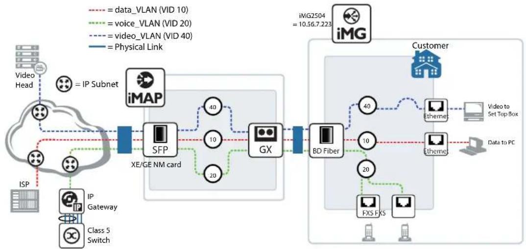
flowchart
graph LR
    subgraph_VideoHead["Video Head"]
        A["IP Subnet"] --> B["iMAP"]
        C["Class 5 Switch"] --> D["IP Gateway"]
        E["ISP"] --> F["IP Gateway"]
        G["Class 5 Switch"] --> H["Class 5 Switch"]
    end

    subgraph_SFP["XE/GE NM card"]
        I["SFP"] --> J["GX"]
        K["40"] --> L["10"]
        M["20"] --> N["10"]
        O["40"] --> P["10"]
        Q["10"] --> R["10"]
        S["10"] --> T["10"]
        U["10"] --> V["10"]
        W["10"] --> X["10"]
        Y["10"] --> Z["10"]
        AA["10"] --> AB["10"]
        AC["10"] --> AD["10"]
        AE["10"] --> AF["10"]
        AG["10"] --> AH["10"]
        AI["10"] --> AJ["10"]
        AK["10"] --> AL["10"]
        AM["10"] --> AN["10"]
        AO["10"] --> AP["10"]
        AQ["10"] --> AR["10"]
        AS["10"] --> AT["10"]
        AU["10"] --> AV["10"]
        AW["10"] --> AX["10"]
        AY["40"] --> Z
    end

    subgraph_iMG2504["iMG2504 = 10.56.7.223"]
    end

    subgraph_Customer["iMG"]
        B
        I
        J
        K
        L
        M
        N
        O
        P
        Q
        S
        T
        U
        V
        X
        Y
        Z
        AA
        AB
        AC
        AD
        AE
        AF
        AG
        AH
    end

    style VideoHead fill:#f9f,stroke:#333
    style iMG2504 fill:#ccf,stroke:#333
    style Customer fill:#cfc,stroke:#333
FIGURE 7-1 Configuration for MGCP
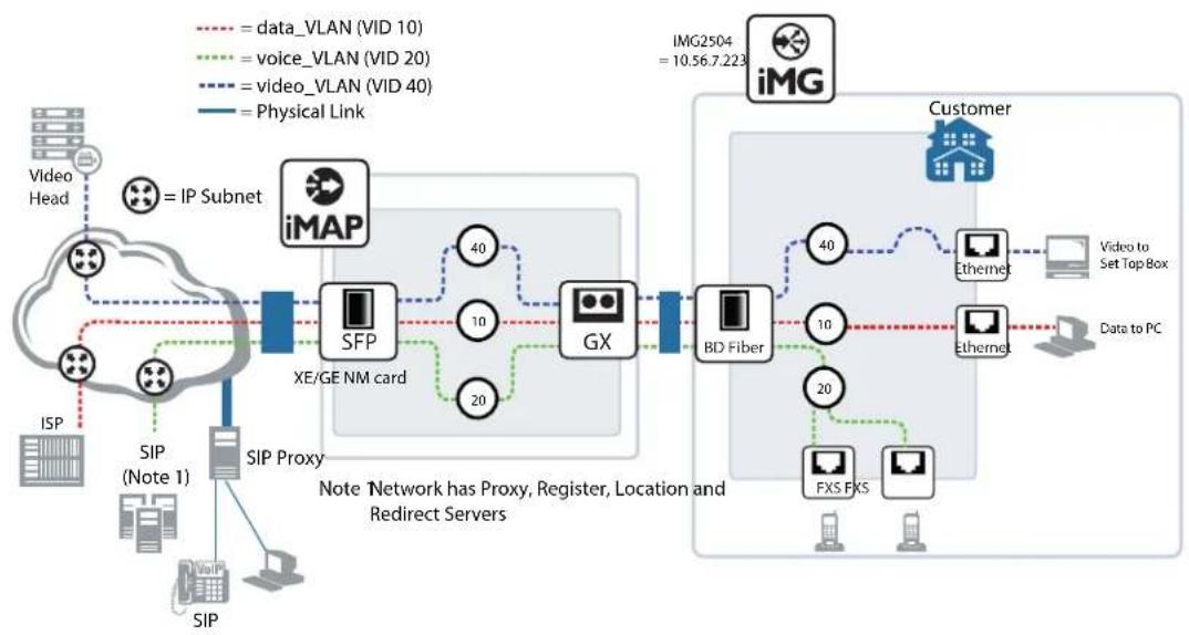
flowchart
graph TD
    A["Video Head"] -->|= IP Subnet| B["iMAP"]
    C["SIP (Note 1)"] -->|SIP Proxy| D["SFP"]
    D --> E["XE/GE NM card"]
    E --> F["GX"]
    F --> G["BD Fiber"]
    G --> H["Customer"]
    I["ISP"] --> J["SIP"]
    K["Data to PC"] --> L["Etherne"]
    M["FXS FXS"] --> N["20"]
    O["40"] --> P["10"]
    Q["20"] --> R["10"]
    S["40"] --> T["10"]
    U["img2504 = 10.56.7.223"] --> V["iMG"]
    style A fill:#f9f,stroke:#333
    style C fill:#f9f,stroke:#333
    style B fill:#ccf,stroke:#333
    style D fill:#ccf,stroke:#333
    style E fill:#ccf,stroke:#333
    style F fill:#ccf,stroke:#333
    style G fill:#ccf,stroke:#333
    style H fill:#ccf,stroke:#333
    style I fill:#ccf,stroke:#333
    style J fill:#ccf,stroke:#333
    style K fill:#ccf,stroke:#333
    style L fill:#ccf,stroke:#333
    style M fill:#ccf,stroke:#333
    style N fill:#ccf,stroke:#333
    style O fill:#ccf,stroke:#333
    style P fill:#ccf,stroke:#333
    style Q fill:#ccf,stroke:#333
    style R fill:#ccf,stroke:#333
    style S fill:#ccf,stroke:#333
    style T fill:#ccf,stroke:#333
    style U fill:#ccf,stroke:#333
FIGURE 7-2 Configuration for SIP
7.2.2 Basic Command Sequences for Provisioning
Refer to Table 1-2, which lists the Modes used for the command set, how to access them, and what they provide.
MGCP and SIP provisioning usually follow a command sequence that starts at a high level (select the protocol, system-wide attributes), provisions the ports for the protocol, and then associates the ports with specific attributes for the subscriber/endpoints.
This sequence is shown in the following tables.
Table7-5 is for MGCP with the following attributes:
Table7-6 is for SIP with the following attributes:
Table 7-2: Example Sequence for MGCP
| Go to Level Task Example Command Notes | |||
| mgcp (from Voice Service) 1 - Enable protocol call service | |||
| 2 - Associate protocol to voice VLAN | bind source-interface vlan20 | ||
| Voice Service 3 - Configure country cptone us | |||
| Voice Port 4 - Configure voice port and activate | voice-port tell (to access) no shutdown | ||
| mgcp (protocol) 5 - Configure mgcp client and identify call agent address | call agent 10.52.142.6 | ||
Table 7-3: Example Sequence for SIP
| Go to Level Task Example Command | Notes | ||
| sip (from Voice Service) (config-serv-sip) | 1 - Enable protocol call service | ||
| 2 - Associate protocol to voice VLAN | bind source-interface vlan20 | ||
| Voice Service (config-voi-serv) | 3 - Configure country | cptone us | |
| Voice Port (config-voiceport) | 4 - Configure voice port and activate | voice-port tell (to access) no shutdown | |
| 5 - Configure other voice port and activate | voice-port tel2 (to access) no shutdown | ||
| Dial Peer (config-dial-peer) | 6 - Configure incoming dial peer ports | dial-peer voice 1 pots (to access) destination pattern 20800 | |
| 7 - Configure outgoing dial peer for termination to SIP softswitch | dial peer voice 3 voip (to access) destination-pattern x.T | ||
| 8 - Define user address and Authentication Password | dial-peer voice 1 (to access) authentication username john pass-word john_pw | ||
| sip (protocol) (config-sip-ua) | 9 - Configure SIP User Agent and identify proxy server address | sip-server 10.52.142.6 |
Table 7-3: Example Sequence for SIP
| Go to Level Task Example Command | Notes | ||
| Voice Applications (access codes)(config-voipapp-fac) | 10 - Define prefixes required prefix '*'call forward all 66call forward all cancel 76call-waiting 67call-waiting cancel 77conference 757transfer blind 545transfer consult 454 | ||
| Supplementary Services(config-voipapp-suppl-serv-port) | 11 - Set up services on a port port tell (to access)call forward all 919-645-5530transfer-mode consulttransfer-mode blindconferencehold-resume | ||
| Voice Port(config-voiceport) | 12 - Activate service voice-port tell (to access)call waiting | Can repeat tell commands |
| (config) | |||||||
| (config-voi-serv) (config-voi-serv) | ③ ④ | ⑤ ⑥ (config-voiceport) | ⑦ • ⑨ (config-dialpeer) | ⑩11 (config-sip-ua) | ○ (configvoipapp-fac) | ⑫ (configvoipapp-supl-serv-port) | ⑬ (config-voiceport) |
| ① ② (config-serv-sip) | |||||||
FIGURE 7-3 Command Levels for SIP Example (Table 7-5)
7.3 Command Reference
7.3.1 Voice Service Logging
This subsection describes the debug command for voice
Table 7-4: Voice Log Commands (config)
| Commands |
| debug voip category (config) |
DEBUG VOIP CATEGORY (CONFIG)
| Syntax | debug voip <[category] | [level] | [verbosity]>no debug voip [category] |
Description Set the logging system to enable or disable voice logging for one or more categories.
Use the no variant to disable a specific or all categories or
Feature VoIP Commands
Mode Privileged Exec and Global Configuration Mode
Release 4.1
Options
| Option Description Range | Default Value | |
| category The type of voip activity or protocol. Values are:aep - Analog Endpointca - Call Agentconfig - Configurationdrv - DSP abstraction layerdrvtone - Driver - fax and modem tonesgwa - Gateway Information (user db, memory, etcmep - Media Endpointmgcp - Media Gateway Control Protocol. Within mgcpare event, general, and msg.sdp - Session Description Protocalsep - Signalling Endpointsigcon - Signalling Connectionsip - Session Initiation Protocol. Within sip are event,general, and msgvrg VRG interface for Broadcom platforms | NA all | |
| level Sets the level of the output. Values are:debug - Set application log to output debug level messageserror - Set application log to output error level messagesnotice - Set application log to output notice level messages | NA error | |
| verbosity The amount of detail for each log. Values are:high - Enable medium format process name and timestamplow - Enable basic output message formatmedium - Enable low format plus function name and line number | NA medium |
Note
By default all voip logs are enabled at error level. To do selective logging the best strategy is to disable all voip logs (no debug voip) then enable the desired ones at teh appropriate level. Refer to the example.
Example See the following commands for option:
awplus(config)# do show log config

Permanent Log:
Status ..... Enabled
Filters:
    Level ..... debug
    Program .....
    Level ..... notices
    Program .....
    Level ..... errors
    Program ..... httpd sshd telnetd swupdate snmpd igmp access voip

Under Voip subcategory:
    The verbosity is: Medium
    aep ..... Enabled
    ca ..... Enabled
    config ..... Enabled
    drv ..... Enabled
    drvtones ..... Enabled
    gwa ..... Enabled
    mep ..... Enabled
    mgcp ..... Enabled
    mgcpEvent ..... Enabled
    mgcpMsg ..... Enabled
    sdp ..... Enabled
    sep ..... Enabled
    sigcon ..... Enabled
    sip ..... Enabled
    sipevent ..... Enabled
    sipMsg ..... Enabled
    vrg ..... Enabled

awplus(config)# no debug voip <!-- disables all subcategories
awplus(config)# do show log config

Permanent Log:
Status ..... Enabled
Filters:
    Level ..... debug
    Program .....
    Level ..... notices
    Program .....
    Level ..... errors
    Program ..... httpd sshd telnetd swupdate snmpd igmp access voip

Under Voip subcategory:
    The verbosity is: Medium
    aep ..... Disabled
    ca ..... Disabled
    config ..... Disabled
    drv ..... Disabled
    drvtones ..... Disabled
    gwa ..... Disabled
Voice Management Command Reference
mep ....... Disabled
mgcp ....... Disabled
mgcpEvent ....... Disabled
mgcpMsg ....... Disabled
sdp ....... Disabled
sep ....... Disabled
sigcon ....... Disabled
sip ....... Disabled
sipevent ....... Disabled
sipMsg ....... Disabled
vrg ....... Disabled

awplus(config)# debug voip category mgcp event <!-- Enabling one subcategory
awplus(config)# do show log config

Permanent Log:
Status ..... Enabled
Filters:
Level ..... debug
Program ......
Level ..... notices
Program ......
Level ..... errors
Program ..... httpd sshd telnetd swupdate snmpd igmp access voip

Under Voip subcategory:
The verbosity is: Medium
aep ..... Disabled
ca ..... Disabled
config ..... Disabled
drv ..... Disabled
drvtones ..... Disabled
gwa ..... Disabled
mep ..... Disabled
mgcp ..... Disabled
mgcpEvent ..... Enabled    <!-- Only one Enabled
mgcpMsg ..... Disabled
sdp ..... Disabled
sep ..... Disabled
sigcon ..... Disabled
sip ..... Disabled
sipevent ..... Disabled
sipMsg ..... Disabled
vrg ..... Disabled
7.3.2 Voice Service Command List (config-voi-serv)
This subsection provides an alphabetical reference of configure, clear, and show commands related to activating and deactivating voice service.
Table 7-5: Voice Service Commands (config-voi-serv)
| Commands |
| cptone (config-voi-serv) |
| dtmf-relay voip (config-voi-serv) |
| fax protocolt38 (config-voi-serv) |
| ip rtp precedence (config-voi-serv) |
| ip signaling precedence (config-voi-serv) |
| rtp behavior discard-when-remote-unknown (config-voi-serv) |
| rtp behavior discard-when-source-unknown (config-voi-serv) |
| rtp payload-type (config-voi-serv) |
| shutdown (config-voi-serv) |
| tone incoming (config-voi-srv) |
CPTONE (CONFIG-VOI-SERV)
Syntax
cptone
[no] cptone
Description
Configure the voice port to utilize a specific countries tone set for items such as Dial Tone etc.
Use the no variant of reset it to the default IT.
Feature VoIP Commands
Mode Voice Service Configuration Mode
Release 4.1
Options
| Option Description Range | Default Value | ||
| ISO specific set of country codes - default is "IT". Refer to 7.1.4.2 for a country tones listing. | NA IT | ||
Note
This triggers the restart of DSP, so this will take time to finish. Also, this does not change the hook qualification timers, so you should change these if necessary.
Example See the following commands for option:
awplus# (config)# voice service voip
awplus(config-voi-serv)# cptone US
DTMF-RELAY VOIP (CONFIG-VOI-SERV)
Syntax
dtmf-relay voip mode <rtp-nte | sip-info>
no dtmf-relay
Description
This command enables dtmf-relay support for the transmission of DTMF events.
The mode indicates whether the digits should be transmitted as rtp events (RFC2833), SIPINFO messages (only when SIP is enabled), or InBand (no dtmf-relay), as follows:
- rtp-nte = DTMF are sent via RFC2833. The real usage of RFC2833 will depend on the result of the negotiation phase for media attributes.=
- sip-notify = DTMF are sent via SIP INFO messages. It applies only when SIP protocol is used.
- in-band = DTMF are sent in band, i.e. using the same RTP speech codec used for the voice path.
Use the no variant of this command to disable the dtmf relay (inband).
Feature VoIP Commands
Mode Voice Service Configuration Mode
Release 4.1
Options
| Option Description Range | Default Value | ||
| - use RFC2833 to transmit DTMF digits sip-info - use SIP Notify Messages to transmit the digits | NA rtp-nte | ||
Note NA
Example See the following commands for options
CLI capture:
Enter configuration commands, one per line. End with CNTL/Z.
awplus(config)# voice serv voip
awplus(config-voi-srv)# dtmf-relay voip mode ?
rtp-nte Use RTP Network Terminal Events to transmit the digits
sip-info Use SIP Info Messages to transmit the digits
awplus(config-voi-srv)# dtmf-relay voip mode rtp-nte ?
awplus(config-voi-srv)# dtmf-relay voip mode sip-info ?
awplus(config-voi-srv)# no dtmf-relay ?
FAX PROTOCOLT38 (CONFIG-VOI-SERV)
Syntax
fax protocol t38
[no] fax protocol t38
Description
This command enables activation of T38 upon detection of FAX.
Feature VoIP Commands
Mode Voice Service Configuration Mode
Release 4.1
Options NA
Note T.38 is only supported for SIP.
Example See the following commands:
awplus# (config)# voice service voip
awplus(config-voi-serv)# fax protocol t38
IP RTP PRECEDENCE (CONFIG-VOI-SERV)
Syntax
ip rtp precedence
[no] ip rtp precedence
Description
This command specifies the DSCP value to be used for all voice traffic (RTP traffic).
Use of the no option restores the value to the default.
Feature VoIP Commands
Mode Voice Service Configuration Mode
Release 4.1
Options
| Option Description Range | Default Value | |
| value DSCP value to be used in IP packet 0-63 0 |
Note NA
Example See the following commands:
awplus# (config)# voice service voip
awplus(config-voi-serv)#ip rtp precedence 46
IP SIGNALING PRECEDENCE (CONFIG-VOI-SERV)
Syntax
ip signaling precedence
[no] ip signalling
Description
This command specifies the DSCP value to be used for all Voip Signaling. Valid values are from 0 to 63.
The default value is 0.
The no option on this command restores the value to it's default
Feature VoIP Commands
Mode Voice Service Configuration Mode
Release 4.1
Options
| Option Description Range | Default Value | |
| value DSCP value to be used for signaling traffic 0-63 0 |
Note NA
Example See the following commands:
awplus# (config)# voice service voip
awplus(config-voi-serv)# ip signaling precedence 46
RTP BEHAVIOR DISCARD-WHEN-REMOTE-UNKNOWN (CONFIG-VOI-SERV)
Syntax
rtp behavior discard-when-remote-unknown no rtp behavior discard-when-remote-unknown
Description
This command forces the voice stack to accept or discard RTP frames that arrive from a remote peer when the IP address of the remote peer specified in the SDP connection field is null (0.0.0.0). The no option returns this parameter to the default (accept unknown frames).
Feature VoIP Commands
Mode Voice Service Configuration Mode
Release 4.2
Options NA
Note NA
Example See the following command:
awplus(config-voi-serv)# no rtp behavior discard-when-remote-unknown
RTP BEHAVIOR DISCARD-WHEN-SOURCE-UNKNOWN (CONFIG-VOI-SERV)
Syntax
rtp behavior discard-when-source-unknown no rtp behavior discard-when-source-unknown
Description
This command forces the voice stack to accept or discard RTP frames that arrive from a remote peer having an IP address when the IP address that differs from the IP address specified in the SDP connection field.
The no option returns this parameter to the default (drop frames in case of IP adresses mismatch).
Feature VoIP Commands
Mode Voice Service Configuration Mode
Release 4.2
Options NA
Note NA
Example See the following command:
awplus(config-voi-serv)# rtp behavior discard-when-source-unknown
RTCP (CONFIG-VOI-SERV)
Syntax
rtcp
[no] rtcp
Description This command enables or disables RTCP for voice traffic
The no option returns this parameter to the default.
Feature VoIP Commands
Mode Voice Service Configuration Mode
Release 4.1
Options NA
Note NA
Example See the following commands:
awplus# (config)# voice service voip awplus(config-voi-serv)# rtcp
RTP PAYLOAD-TYPE (CONFIG-VOI-SERV)
Syntax
rtp payload-type nte
no rtp payload-type nte
Description
This command specifies Payload-type to be used for RTP Named Terminal Events. Valid range is 94 to 127. Default is 97.
The no option returns this parameter to the default.
Feature VoIP Commands
Mode Voice Service Configuration Mode
Release 4.1
Options
| Option Description Range | Default Value | ||
| nte Named Telephone Events. NA NA | |||
| number | The value used for the name telephone event payload. | 96-127 | 97 |
Note NA
Example See the following commands.:
awplus# (config)# voice service voip
awplus(config-voi-serv)# rtp payload-type nte 98
SHUTDOWN (CONFIG-VOI-SERV)
Syntax
shutdown
[no] shutdown
Description
This command disables or enables the voip service on the device
Feature Voice Commands
Mode Voice Service Configuration Mode
Release 4.1
Options NA
Note
To enable, the user protocol must have already been specified.
Example See the following commands:
awplus# (config)# voice service voip
awplus(config-voi-serv)# shutdown
TONE INCOMING (CONFIG-VOI-SRV)
Syntax tone incoming ans-all disable echo suppressor [no] tone incoming
Description Activate to enable Tone detection (2100-Hz Answer (ANS)) and to disable the echo canceller. The No option disables tone detection.
Feature VoIP Commands
Mode Voice Service Configuration Mode
Release 4.1
Default Tone incoming ans-all disable echo suppressor
Note NA
Example See the following commands:
awplus# (config)# voice service voip awplus(config-voi-serv)# tone incoming ans-all disable echo suppressor
7.3.3 Enable/Disable MGCP Command List (config-serv-mgcp)
This chapter provides an alphabetical reference of configure, clear, and show commands related to enabling and disabling MGCP service.
Table 7-6: MGCP Service Commands (config-serv-mgcp)
| Commands |
| bind (config-serv-mgcp) |
| call service restart (config-serv-mgcp) |
| call service (config-serv-mgcp) |
| listen-port (config-serv-mgcp)t |
BIND (CONFIG-SERV-MGCP)
Syntax
bind source-interface
Description
This command specifies the vlan interface that the MGCP client should use to source and receive both signalling and rtp traffic.
Feature VoIP Commands
Mode Voice Service Configuration Mode
Release 4.1
Options
| Option Description Range | Default Value | ||
| The name of the interface - that the MGCP Signalling and RTP traffic should originate from. | NA NA | ||
Note NA
Example Refer to the following commands:
aw(config-voi-serv)#plus# (config)# voice service voip awplus(config-voi-serv)#mgcp awplus(config-serv-mgcp)# bind source-interface vlan115
CALL SERVICE RESTART (CONFIG-SERV-MGCP)
Syntax
call service restart [forced]
Description This command triggers the restart of the MGCP Client
Forces MGCP client on the device to restart. Note that the forced option is mandatory - and forces all existing calls to get torn down.
Feature VoIP Commands
Mode Voice Service Configuration Mode
Release 4.1
Options
| Option Description Range | Default Value | |
| forced No graceful end to existing calls. MGCP client will destroy existing calls and restart. (Mandatory) | NA forced |
Note NA
Example Refer to the following commands:
aw(config-voi-serv)#plus# (config)# voice service voip awplus(config-voi-serv)#mgcp awplus(config-serv-mgcp)# call service restart forced
CALL SERVICE (CONFIG-SERV-MGCP)
Syntax
call service
[no] call service
Description
This command disables or enables MGCP Protocol.
Feature VoIP Commands
Mode Voice Service Configuration Mode
Release 4.1
Options NA
Note NA
Example Refer to the following commands:
aw(config-voi-serv)#plus# (config)# voice service voip awplus(config-voi-serv)#mgcp
awplus(config-serv-mgcp)# call service
LISTEN-PORT (CONFIG-SERV-MGCP)
Syntax
listen-port
[no] listen-port
Description
This command specifies the port that the MGCP Client should listen on for MGCP Signalling. The no form of the command resets it to the default value of 2427.
Feature VoIP Commands
Mode Voice Service Configuration Mode
Release 4.1
Options
Option Description Range
Default
Value
port-num The IP Port number that SIP Signalling is expected to arrive on.
NA 2427
Note NA
Example Refer to the following commands:
aw(config-voi-serv)#plus# (config)# voice service voip
awplus(config-voi-serv)#mgcp
awplus(config-serv-mgcp)# listen-port 2440
7.3.4 Enable/Disable SIP Command List (config-serv-sip)
This chapter provides an alphabetical reference of configure, clear, and show commands related to enabling and disabling SIP service.
Table 7-7: SIP Service Commands (config-serv-sip)
| Commands |
| bind (config-serv-sip) |
| call service restart (config-serv-sip) |
| call service (config-serv-sip) |
| hairpin (config-serv-sip) |
| listen-port (config-serv-sip) |
| localhost (config-serv-sip) |
BIND (CONFIG-SERV-SIP)
Syntax
bind source-interface <interface_id>
[no] bind
Description
This command binds SIP Signalling and RTP Traffic to a specific interface. Specifies the source interface that the SIP Client should use to source & receive both signalling and rtp traffic.
The no form of this command restores IP interface back to default: vlan1.
Feature Voice-SIP Commands
Mode Voice Service Configuration Mode
Release 4.1
Options
| Option Description | Range | Default Value | |
| interface_id The | name of the interface - here it is the form "vlan". | NA NA |
Note NA
Example Refer to the following commands:
awplus# (config)# voice service voip
awplus (config-voi-serv) #sip
awplus(config-serv-sip)#bind source-interface vlan115
CALL SERVICE RESTART (CONFIG-SERV-SIP)
Syntax
call service restart [forced]
Description This command triggers restart of the SIP Client
Forces the SIP client on the device to restart. Note that the forced parameter is mandatory - and forces all existing calls to get torn down.
Feature Voice-SIP Commands
Mode Voice Service Configuration Mode
Release 4.1
Options
| Option Description Range | Default Value | |
| forced No graceful end to existing calls. SIP Client will destroy existing calls and restart (Mandatory) | NA forced |
Note NA
Example Refer to the following commands:
awplus# (config)# voice service voip
awplus (config-voi-serv) #sip
awplus(config-serv-sip)#call service restart forced
CALL SERVICE (CONFIG-SERV-SIP)
Syntax
call service
[no] call service
Description This command disables or enables SIP Client.
Command enables - or disables SIP client. Disable is done without preserving existing calls.
Feature Voice-SIP Commands
Mode Voice Service Configuration Mode
Release 4.1
Options NA
Note NA
Example Refer to the following commands:
awplus# (config)# voice service voip
awplus(config-voi-serv)#sip
awplus(config-serv-sip)#call service
HAIRPIN (CONFIG-SERV-SIP)
Syntax
hairpin
[no] hairpin
Description This command allows SIP Signalling to terminate on the same device
When enabled, SIP Signalling is allowed to terminate on the same device it originated from without going to an external device. As a result, no signalling is sent to the configured ProxyServer.
The no form of the command resets this capability to the default - which is disabled.
Feature Voice-SIP Commands
Mode Voice Service Configuration Mode
Release 4.1
Options NA
Note This command does not include RTP traffic; it will perform a hairpin if instructed by the signaling protocol.
Example Refer to the following commands:
awplus# (config)# voice service voip
awplus(config-voi-serv)#sip
awplus(config-serv-sip)#hairpin
LISTEN-PORT (CONFIG-SERV-SIP)
Syntax
listen-port
[no] listen-port
Description
This command specifies the port for the SIP Client to listen on for SIP Signalling traffic.
Specifies the port that the SIP Client should listen on for SIP Signalling. The no form of the command resets it to the default value of 5060.
Feature VoIP Commands
Mode Voice Service Configuration Mode
Release 4.1
Options
| Option Description Range | Default Value | ||
| port-num The IP | Port number that SIP Signalling is expected to arrive on. | NA 5060 | |
Note NA
Example Refer to the following commands:
awplus# (config)# voice service voip
awplus(config-voi-serv)#sip
awplus(config-serv-sip)#listen-port 5080
LOCALHOST (CONFIG-SERV-SIP)
Syntax
localhost dns domain
[no] localhost
Description
This command configures the gateway to substitute a DNS hostname or domain as the localhost instead of the IP address.
Feature VoIP Commands
Mode Voice Service Configuration Mode
Release 4.1
Options
| Option Description Range | Default Value | |
| domain The DNS domain - including a domain name and optionally a hostname. | NA NA |
Note NA
Example Refer to the following commands:
awplus# (config)# voice service voip
awplus(config-voi-serv)#sip
awplus(config-serv-sip)#localhost dns somedomain
7.3.5 Configure MGCP Protocol Command List (config-mgcp)
This chapter provides an alphabetical reference of configure, clear, and show commands related to configuring the MGCP protocol.
Table 7-8: MGCP Protocol Commands (config-mgcp)
| Commands |
| backup-call-agent (config-mgcp) |
| behavior heartbeat (config-mgcp) |
| behavior rsip-range (config-mgcp) |
| call-agent (config-mgcp) |
| domain (config-mgcp) |
| endpoint offset (config-mgcp) |
| package-capability lcs-package (config-mgcp) |
| persistent (config-mgcp) |
| piggyback message (config-mgcp) |
| request retries (config-mgcp) |
| request timeout (config-mgcp) |
| rtp payload-type (config-mgcp) |
| show mgcp |
BACKUP-CALL-AGENT (CONFIG-MGCP)
Syntax
backup-call-agent
[no] backup-call-agent
Description
This command specifies the secondary Call Agent that the MGCP Client will attempt to register with.
Note that the service-type is inherited from the configured primary call-agent. Once configured, the MGCP client can start to communicate with the Call Agent
Feature Voice-MGCP Commands
Mode MGCP Configuration Mode
Release 4.1
Options
| Option Description Range Default Value | |||
| IPV4 IP Address used as the destination for MGCP signalling | NA NA | ||
| host-name The | qualified hostname that is used as the destination for MGCP Signalling. | NA NA | |
| The port number that the MGCP Call Agent signalling is sent to. | NA 2727 | ||
Note
to know which Call Agent the iMG is actually registered to, use the show mgcp command and check the information reported in the bottom lines for the Endpoints Active Agent status.
Example Refer to Refer to the following commands:
iMG1525RF-214# show mgcp
Admin State ENABLED
Call agent: 172.30.1.228 2727 service is MGCP
Backup call agent: 172.30.1.229 2727
Gateway Source Interface: vlan203
Gateway Port : 2427
DTMF-relay for VoIP is inband for all codec types
Tone detection is ans-all disable echo suppressor
T.38 Fax is ENABLED
NTE payload type is DYNAMIC
RTP Payload type for nte is 101
RTP precedence: 0
RTP discard on unknown remote is ENABLED
RTP discard on mismatched source is ENABLED
RTCP ENABLED
Piggyback msg ENABLED
Heartbeat message is: DISABLED
Heartbeat master port is *
Heartbeat refresh timeout is: 15 seconds
Rsip-range use is : INDIVIDUAL
Request timeout: 20 seconds
Request retries: 7
Signaling precedence: 0
Domain: [\$IP]
Voice Management Command Reference
Package capability: basic-package, dtmf-package, gm-package, line-package, rtp-package Endpoint offset is DISABLED Persistent Events: none Endpoints: aaln/0 port: tel1 Admin State ENABLED Oper State Up Call State Idle Active Agent Primary Endpoints: aaln/1 port: tel2 Admin State ENABLED Oper State Up Call State Idle Active Agent Primary
BEHAVIOR HEARTBEAT (CONFIG-MGCP)
| Syntax | behavior heartbeat {NTFY | RSIP-Refresh | RSIP-keepalive} <seconds> [master |
| [no] behavior heartbeat |
Description This command enables and disables the Heartbeat mechanism, configure the interval between heartbeat messages, as well as specify the messaging used. This feature is used to ensure that the call-agent is aware of the devices in the network - and the current state of those devices.
Feature Voice-MGCP Commands
Mode MGCP Configuration Mode
Release 4.1
Options
| Option Description Range | Default Value | ||
| NTFY Use the Notify Message with "N:hb" indication NA NA | |||
| RSIP-Refresh Use the RSIP Message with the "RM:x-refresh" parameter NA NA | |||
| RSIP-keepalive Use the RSIP Message with the "RM:x-keepalive" parameter | NA NA | ||
| master | Specifies the port that manages the heartbeat: tell or tel2 or * for both. If this port fails, all other ports are failed. | NA | * |
| The number of seconds between transmission of messages. | NA 10 | ||
Note NA
Example Refer to the following commands:
awplus# (config)# mgcp
awplus(config-mgcp)# behavior heartbeat NTFY 10
BEHAVIOR RSIP-RANGE (CONFIG-MGCP)
Syntax behavior rsip-range {all|none}
Description This command specifies whether the MGCP Client will transmit RSIPs for all ports on the device, or for each port.
Feature Voice-MGCP Commands
Mode MGCP Configuration Mode
Release 4.1
Options
| Option Description Range | Default Value | |
| {all|none} all implies that the RSIP Range will be used. None implies that it will not be used. The default is none. | NA none |
Note NA
Example Refer to the following commands:
awplus# (config)# mgcp
awplus(config-mgcp)# behavior rsip-range all
CALL-AGENT (CONFIG-MGCP)
Syntax
call-agent
Description This command specifies the call agent and protocol variant
Specifies the primary Call Agent that the MGCP Client will attempt to register with. Also allows the user to specify the service-type or variant of the protocol that is
Feature Voice-MGCP Commands
Mode MGCP Configuration Mode
Release 4.1
Options
| Option Description Range | Default Value | ||
| IPV4 IP Address used as the destination for MGCP signalling | NA NA | ||
| host-name The | qualified hostname that is used as the destination for MGCP Signalling. | NA NA | |
| The port number that the MGCP Call Agent signalling is sent to. | NA 2727 | ||
| service-type The | version of the MGCP Protocol that is being used.MGCP implies MGCP 1.0. MGCP-NCS implies NCS 1.0. | NA NA | |
Note NA
Example Refer to the following commands:
awplus# (config)# mgcp
awplus(config-mgcp)# call-agent 10.52.90.17 2400 service-type mgcp
DOMAIN (CONFIG-MGCP)
Syntax domain
Description This command specifies the format and contents of the Domain Name - used in the source address in MGCP client signalling.
Use the no form of the command to reset the value to the default (The ip address of the device)
Feature Voice-MGCP Commands
Mode MGCP Configuration Mode
Release 4.1
Options
| Option Description Range | Default Value | ||
| Address used as the destination for MGCP signalling | NA NA | ||
| domainstr Can be | any valid string or IP,MAC, or Host, where means have these values substituted | NA [$IP] | |
| mac The MAC A | address that is used as the Domain for MGCP Signalling. | NA NA | |
Note NA
Example Refer to the following commands:
awplus# (config)# mgcp
awplus(config-mgcp)# domain 10.53.44.23
ENDPOINT OFFSET (CONFIG-MGCP)
Syntax
endpoint offset [no] endpoint offset
Description
This command, when enabled, marks the endpoint address (aaln/#) starting from 1 rather than the default, starting from 0 (aaln/0). This, combined with the domain attribute, is used to define the endpoint identifier.
Feature Voice-MGCP Commands
Mode MGCP Configuration Mode
Release 4.1
Options NA
Note NA
Example Refer to the following commands:
awplus# (config)# mgcp awplus(config-mgcp)# endpoint offset
PACKAGE-CAPABILITY LCS-PACKAGE (CONFIG-MGCP)
Syntax package-capability lcs-package no package-capability lcs-package
Description Configure MGCP to add the Line Control Signaling (RFC3660 lcs-package) to the package capabilities list. The No option returns to the default setting.
Feature Voice-MGCP Commands
Mode Global Configuration Mode
Release 4.3
Options NA
Default For MGCP service type, lcs-package is disabled. For MGCP-NCS service-type, lcs-package is enabled.
Note NA
Example Refer to the following commands:
awplus# configure terminal awplus(config)# mgcp awplus(config-mgcp)# package-capability lcs-package
PERSISTENT (CONFIG-MGCP)
Syntax
persistent [hookflash|offhook|onhook|digits] no persistent [hookflash|offhook|onhook|digits]
Description
Configure the persistence of hook-events and digits for MGCP. This command is used to enable the persistence of hook-events with MGCP call-agent that sometimes does not provide a RequestedEvents parameter in RQNT NotificationRequest messages during hook-events. Also used to enable the ability to send digits when the call-agent does not request the digits. The No option of this command returns the settings to their default value.
Feature Voice-MGCP Commands
Mode Global Configuration Mode
Release 4.3
Options
| Option Description Range | Default Value | ||
| hookflash Telephone hook-flash event NA NA | |||
| offhook Telephone off-hook event | NA | NA | |
| onhook Telephone on-hook event | NA | NA | |
| digits | Digits dialed or digits pressed during a call | NA | NA |
Default For MGCP service-type, all event-types are disabled.
For MGCP-NCS service-type, hookflash, offhook and onhook are enabled, digits is disabled.
Note NA
Example Refer to the following commands:
awplus# configure terminal
awplus(config)# mgcp
awplus(config-mgcp)# persistent
This command, when enabled, allows the MGCP Client to send multiple messages in one packet. This can reduce messaging overhead. As reported in RFC2705, piggyback refers to the support for a call agent to send several messages to the gateway using the same udp message and separating each message by a line of text containing a single dot. By default this is enabled.
Feature Voice-MGCP Commands
Mode Global Configuration Mode
Release 4.1
Options NA
Note NA
Example Refer to the following commands:
awplus# (config)# mgcp
awplus(config-mgcp)# no piggyback message
REQUEST RETRIES (CONFIG-MGCP)
Syntax
request retries
Description
This command specifies the number or retransmissions to attempt when no response received for MGCP Signaling.
Specifies the number of time the client will re-transmit an MGCP protocol message - prior to giving up....and possibly switching over to the backup call-agent.
Use the no form of this command to reset the value to the default
Feature Voice-MGCP Commands
Mode MGCP Configuration Mode
Release 4.1
Options
| Option Description Range | Default Value | |
| The number of times a message is retransmitted. NA 7 |
Note NA
Example Refer to the following commands:
awplus# (config)# mgcp
awplus(config-mgcp)# request retries 5
REQUEST TIMEOUT (CONFIG-MGCP)
Syntax
request timeout
[no] request timeout
Description
This command specifies the maximum time a message waiting for an acknowledge can stay in the network before the endpoint enters in the disconnect procedure.
Description The No form of this command resets the value to the default (20 secs)
Feature Voice-MGCP Commands
Mode MGCP Configuration Mode
Release 4.1
Options
| Option Description Range | Default Value | |
| The number of seconds that the MGCP Client will wait for a response. Default is 20. | NA 20 |
Note
Timeout period is specified in seconds instead of milliseconds.
Example Refer to the following commands:
awplus# (config)# mgcp
awplus(config-mgcp)# request timeout 250
RTP PAYLOAD-TYPE (CONFIG-MGCP)
Syntax
rtp payload-type nte {dynamic|static}
no rtp payload-type nte
Description
Configure the RTP NTE (Named Terminal Events) payload-type to static or dynamic for MGCP. The
No form of this command resets the value to the default.
Feature Voice-MGCP Commands
Mode MGCP Configuration Mode
Release 4.3
Options
| Option Description Range | Default Value | |
| dynamic Enable negotiation of NTE payload type. NA NA | ||
| static Force-fixed NTE payload type. | NA NA |
Note NA
Default Dynamic
Example Refer to the following commands:
awplus# configure terminal
awplus(config)# mgcp
awplus(config-mgcp)# rtp payload-type nte static
SHOW MGCP
Syntax show mgcp
Description This command displays the configuration in place for the MGCP Client
Feature Voice-MGCP Commands
Mode Privileged Exec Mode
Release 4.1
Options NA
Note NA
Example Refer to the following commands:
awplus# show mgcp
Admin State ENABLED
Call agent: 172.30.1.228 2727 service is MGCP-NCS
Backup call agent: 172.30.1.229 2727
Gateway Source Interface: vlan203
Gateway Port : 2427
DTMF-relay for VoIP is rtp-nte for all codec types
Tone detection is ans-all disable echo suppressor
T.38 Fax is ENABLED
NTE payload type is DYNAMIC
RTP Payload type for nte is 97
RTP precedence: 0
RTP discard on unknown remote is DISABLED
RTP discard on mismatched source is ENABLED
RTCP DISABLED
Piggyback msg ENABLED
Heartbeat message is: DISABLED
Heartbeat master port is *
Rsip-range use is : INDIVIDUAL
Request timeout: 20 seconds
Request retries: 7
Signaling precedence: 0
Domain: [$IP]
Package capability: basic-package, dtmf-package, gm-package,
lcs-package, line-package, rtp-package
Endpoint offset is DISABLED
Endpoints: aaln/0 port: tell Admin State ENABLED Oper State Up Call State Idle
Endpoints: aaln/1 port: tel2 Admin State ENABLED Oper State Up Call State Idle
Syntax show mgcp service
Description This command displays the status of the MGCP Service (Enabled or Disabled).
Feature Voice-MGCP Commands
Mode Privileged Exec Mode
Release 4.1
Options NA
Note NA
Example Refer to the following commands:
Voice Management Command Reference
awplus# show mgcp service MGCP is Enabled
7.3.6 Configure SIP Protocol Command List (config-sip-ua)
This section provides an alphabetical reference of configure, clear, and show commands related to configuring the SIP protocol.
Table 7-9: SIP Protocol Commands (config-sip-ua)
| Commands |
| authentication method (config-sip-ua) |
| behavior disable-url-matching |
| behavior hook-flash (config-sip-ua) |
| behavior softswitch (config-sip-ua) |
| map alertinfo (config-sip-ua) |
| map alertinfo (config-sip-ua) |
| rellxx |
| show sip service |
| show sip-ua |
| show sip-ua map alertinfo |
| sip-server (config-sip-ua) |
| subscribe message-summary |
AUTHENTICATION METHOD (CONFIG-SIP-UA)
Syntax
authentication method {proxy | www}
[no] authentication method
Description
Specifies the authentication method used in SIP digest authentication. It is possible to enable both methods of authentication by entering the command twice. Use the no form of this command to disable authentication.
Feature Voice-SIP Commands
| Option Description Range | Default Value | |
| Proxy Support Proxy digest authentication method NA NA | ||
| www Support the www digest authentication method NA NA |
Note NA
Example Refer to the following commands:
awplus# configure terminal
awplus# (config)# sip-ua
awplus(config-sip-ua)# authentication method proxy
awplus(config-sip-ua)# authentication method www
BEHAVIOR DISABLE-URL-MATCHING
Syntax
behavior disable-url-matching
no behavior disable-url-matching (default)
Description
Disable URL matching on incoming Request messages.
Feature Voice-SIP Commands
Example Refer to the following commands:
awplus# configure terminal
awplus(config)# sip-ua
awplus(config-sip-ua)# behavior ?
disable-url-matching
BEHAVIOR HOOK-FLASH (CONFIG-SIP-UA)
Syntax
behavior hook-flash {ext-in-call|external|internal|default} no behavior hook-flash
Description
Configure how the iMG processes hook-flash events for call-waiting, three-way call and call-transfers. The iMG can handle these call features internally to behave as an 'intelligent' SIP access device or as a 'non-intelligent' SIP access device and let the call-server handle the call features. To reset to the default, use the no form of this command or use the 'default' option. The default value used depends on the sip-server profile selected (see default setting description).
Feature Voice-SIP Commands
| Option Description Range Default Value | |||
| ext-in-call | Configure hook-flash for external control during a call. Hook-flash events during a call will be handled by SIP INFO. This is a modified version of the 'non-intelligent' mode of operation. | NA | NA |
| external | Configure hook-flash for external control. Hook-flash events will typically be handled by SIP INFO whenever possible. This is the 'non-intelligent' mode of operation. | NA | NA |
| internal | Configure hook-flash for internal control. Hook-flash events will typically be handled by SIP INVITE. This is the 'intelligent' mode of operation. | NA | NA |
| default The | default setting depends on the sip-server profile used (see behavior sip-server command). 'Internal' is the default for all sip-server profiles expect for the Lucent profile which defaults to 'ext-in-call'. | NA | NA |
Default The hook-flash control is set to a preferred setting by the sip-server profile used (see behavior sip-server command):
Hook-flash behavior sip-server profile internal (none), Broadsoft ext-in-call Lucent
The no form of this command will reset the hook-flash behavior to 'Internal' for any of the sip-server profile settings.
Source
The ability to process the incoming SIP INFO messages is controlled by the sip-server profile. So if you receive an INFO message from the Lucent switch it will play CWT tone. However if you attempt to flash-hook its going to send out an INVITE / inactive instead of an INFO / hook-flash. Same rules apply to Broadsoft profile. Having Broadsoft configured will allow the Broadsoft formatted INFO message. If you have changed the hook-flash control from "internal" to "ext-in-call" the hook-flash will cause an INFO / hook-flash instead of handling the call-wait internally. In summary, the sip-server profile setting will configure the SIP INFO message format and set the hook-flash control to a preferred setting. But it can be overridden by the CLI. You should only need to do this for an unexpected operating environment.
Source iMG
Voice Management Command Reference
Example Refer to the following commands:
awplus# configure terminal
awplus(config)# sip-ua
awplus(config-mgcp)# behavior hook-flash internal
BEHAVIOR SOFTSWITCH (CONFIG-SIP-UA)
Syntax
behavior sip-server {lucent | broadsoft} no behavior sip-server (default)
Description
Configures the system softswitch so that it is tailored to work with the specified softswitch. For all other softswitches, the parameter should be left at its default
Feature Voice-SIP Commands
Example Refer to the following commands:
awplus# configure terminal
awplus# (config)# sip-ua
awplus(config-sip-ua)# behavior sip-server lucent
MAP ALERTINFO (CONFIG-SIP-UA)
Syntax map alertinfo
Description This command associates the specified pattern number with the given alert info string. Use the no command to configure the specified pattern # with a default. These patterns also apply to call waiting.
Feature Voice-SIP Commands
| Option Description Range Default Value | |||
| pattern # The pattern number (cadence mappings) that are used.In the USA these are the following:1 - long2 - long long3 - short short long4 - short long short5 - ringsplash6 - short short short7 - short short short short8 - short short short short short9 - short10 - ringsplash | NA NA | ||
| TextString Value of the Alert-Info SIP header(pattern for alert-info 1)(pattern for alert-info 2)(pattern for alert-info 3)(pattern for alert-info 4)(pattern for alert-info 5)(pattern for alert-info 6)(pattern for alert-info 7)(pattern for alert-info 8)(pattern for alert-info 9)(pattern for alert-info 10) | String (shown below)distinctive-ring-1distinctive-ring-2distinctive-ring-3distinctive-ring-4distinctive-ring-5distinctive-ring-6distinctive-ring-7distinctive-ring-8distinctive-ring-9distinctive-ring-10 | ||
Note SIP must be specified as the signaling protocol for this command to work. Also, in a call waiting scenario, the distinctive pattern will carry over (for patterns 1-4).
Example Refer to the following commands:
awplus# configure terminal awplus(config)#sip-ua awplus(config-sip-ua)# map alertinfo 1 Bellcore-drl
MAP ALERTINFO (CONFIG-SIP-UA)
Syntax registrar { [host-name] | ip-addr [port-num]} [secondary] [no] registrar [secondary]
Description This command specifies the location server destination and port-number. Also used to identify whether it is the primary location server - or a backup address.
Use the no form to remove the entry.
Feature Voice-SIP Commands
| Option Description Range | Default Value | ||
| host-name The fully qualified hostname of the SIP Location Server NA NA | |||
| ip-addr The IP address of the SIP Location Server NA NA | |||
| port-num The port number that the Location Server will be listening on. | NA 5060 | ||
| secondary | An indication that this location is the secondary contact, and that attempts to register should first be targeted at the non-secondary entry. | NA NA | |
Note The primary server must always be registered (not secondary only) for SIP service to work.
Example Refer to the following commands:
awplus# configure terminal
awplus# (config)# sip-ua
awplus(config-sip-ua)# registrar 172.30.1.121 5060
awplus(config-sip-ua)# registrar 172.30.1.123 5060 secondary
Voice Management Command Reference
REL1XX
Syntax rel1xx supported 100rel (default) rel1xx disable no rel1xx
Description This command controls whether or not the "100rel" option appears in the SIP SUPPORTED header field. The "100rel" extension provides support for the reliability of provisional responses as defined in RFC-3262.
Feature Voice-SIP Commands
Example Refer to the following commands:
awplus# configure terminal awplus(config)# sip-ua awplus(config-sip-ua)# rellxx supported 100rel
SHOW SIP SERVICE
Syntax
show sip service
Description This command displays the status of the SIP Service
Feature Global Configuration Mode
Mode Privileged Exec Mode
Release 4.1
Options NA
Note NA
Example Refer to the following commands:
awplus# configure terminal awplus# show sip service SIP is Enabled
SHOW SIP-UA
Syntax show sip-ua
Description This command displays configuration of the SIP User Agent, and includes any primary or backup servers if configured.
Feature Global Configuration Mode
Mode Privileged Exec Mode
Release 4.1
Options NA
Note NA
Example Refer to the following commands:
awplus# configure terminal
awplus(config-sip-ua# do show sip-ua
Admin State ENABLED
    registrar: 172.30.1.121 5060
    secondary registrar : 172.30.1.123 5060 (active)
    sip-server: 172.30.1.121 5060 (active)
    secondary sip-server : 172.30.1.123 5060
    Source Interface: vlan2000
    Local host is : 172.30.1.121
    Sip User Port : 5060
    dtmf-relay for VoIP is rtp-nte for all codec types
    tone detection is DISABLED
    T.38 Fax is DISABLED
    rtp Payload type for nte is 97
    rtp precedence: 46
    rtcp is DISABLED
    authentication : proxy, www
    subscribe : DISABLED
    signaling precedence is 32
    Hair pinning of signaling is enabled
    User Agents: 1 port: tel1 Admin State ENABLED Oper State Up Call State Idle
    User Agents: 2 port: tel2 Admin State ENABLED Oper State Up Call State Idle
SHOW SIP-UA MAP ALERTINFO
Syntax show sip-ua map alertinfo
Description This command displays configuration of the alert info string and the cadence.
Feature Global Configuration Mode
Mode Privileged Exec Mode
Release 4.2.3
Options NA
Note NA
Example Refer to the following commands:
awplus# configure terminal
awplus(config-sip-ua# do show sip-ua map alertinfo
Pattern 1 : distinctive-ring-1
Pattern 2 : distinctive-ring-2
Pattern 3 : distinctive-ring-3
Pattern 4 : distinctive-ring-4
Pattern 5 : distinctive-ring-5
Pattern 6 : distinctive-ring-6
Pattern 7 : distinctive-ring-7
Pattern 8 : distinctive-ring-8
Pattern 9 : distinctive-ring-9
Pattern 10 : distinctive-ring-10
SIP-SERVER (CONFIG-SIP-UA)
Syntax sip-server { [host-name] | ip-addr [port-num] } [secondary] [no] sip-server [secondary]
Description Use to specify the softswitch or proxy server destination and port-number. Also use to identify whether it is the primary softswitch - or a backup address. Use the no form to remove the entry.
Feature Voice-SIP Commands
| Option Description Range | Default Value | ||
| host-name The fully qualified hostname of the SIP Proxy Server NA NA | |||
| ip-addr The IP address of the SIP Proxy Server NA NA | |||
| port-num The port number that the Proxy Server will be listening on. | NA 5060 | ||
| secondary | An indication that this is the secondary contact - and that attempts to register should first be targeted at the non-secondary entry. | NA NA | |
Note The primary server must always be registered (not secondary only) for SIP service to work.
Example Refer to the following commands:
awplus# configure terminal awplus# (config)# sip-ua awplus(config-sip-ua)# sip-server 172.30.1.121 5060 awplus(config-sip-ua)# sip-server 172.30.1.123 5060 secondary
SUBSCRIBE MESSAGE-SUMMARY
Syntax subscribe message-summary { [active] | [passive]} no subscribe message-summary
Description This command enables the SIP subscribe service for receiving SIP messages for Message Waiting Indicator (MWI). Entering 'subscribe message summary' without any parameters specified will select the default method defined for the currently selected 'SIP server behaviour' (see sip-ua behavior sip-server command). If LUCENT has been selected then the default message-summary subscribe method is Passive, otherwise all the other server behaviours will use the Active method.
Feature Voice-SIP Commands
| Option Description Range | Default Value | ||
| active When | Active mode is selected, SIP NOTIFY requests will not be accepted without a previous successful SUBSCRIBE exchange. When Passive mode is selected, SIP NOTIFY requests will be accepted independently from a previous successful SUB-SCRIBE exchange. | NA Default | |
| passive When | Passive mode is selected, SIP NOTIFY requests will be accepted independently from a previous successful SUBSCRIBE exchange. | NA NA | |
Note NA
Example To enable message-summary subscribe when Lucent profile has been selected, enter the command:
awplus# configure terminal awplus(config)# sip-ua awplus(config-sip-ua)# subscribe message-summary
awplus# show sip-ua
Admin State ENABLED
registrar: 172.30.1.1 5060 (active)
secondary registrar : not configured
sip-server: 172.30.1.1 5060 (active)
secondary sip-server : not configured
sip-server behavior : Lucent
Source Interface: vlan203
Local host is : not configured
Sip User Port : 5060
dtmf-relay for VoIP is rtp-nte for all codec types
tone detection is ans-all disable echo suppressor
T.38 Fax is ENABLED
rtp Payload type for nte is 97
rtp precedence: 0
rtp discard on unknown remote is DISABLED
rtp discard on mismatched source is ENABLED
Voice Management Command Reference
rtcp is DISABLED
authentication : proxy, www
subscribe : ENABLED
subscribe method : Default
signaling precedence is 0
Hair pinning of signaling is enabled
100rel support is enabled
User Agents: 1 port: tel1 Admin State ENABLED Oper State Up Call State Idle
User Agents: 2 port: tel2 Admin State DISABLED Oper State Disabled Call State Idle
awplus(config-sip-ua)# subscribe message-summary
7.3.7 Configuring Voice Prefix Replacement (config-voi-trans-rule)
This subsection provides an alphabetical reference regarding configure, clear, and show commands related to prefix replacement (also called translation rule).
Table 7-10: SIP Voice Translation Rule Commands (config-voi-trans-rule)
| Commands |
| voice translation-rule |
| rule |
| show voice translation-rule |
VOICE TRANSLATION-RULE
Syntax
voice translation-rule
Description
Creates a new translation set and assigns an identifier
Feature Voice Commands
Mode Global Configuration Mode
Release 4.3
Options
| Option Description Range Default Value | ||
| num An integer that univocally identifies the translation set. 0-429496 | 7295 NA |
Note
It's possible to create more than one translation set but only one can be applied in a given moment to a POTS interface
Example TThe
following command creates a translation set with identifier 3 and then moves the user into config-voi-trans-rule in order to continue with the configuration of the translation rules
awplus# configure terminal awplus# (config)# voice translation-rule 3 awplus(config-voi-trans-rule)#
RULE
Syntax
rule
Description
Creates a new translation rule inside the selected translation set. The rule will look inside the dialed number for the digit-map and if finds a correspondence it will replace the digit-map with the digits (if replace action has been specified) or will add a the digits as prefix (if prefix action has been selected). The default action is replace. The priority value is used to specify which rule is checked first. The lowest priority values have precedence over the highest values. As soon a positive match happens, the action rule is applied.
Feature Voice Commands
Mode Voice Translation Rule Configuration Mode
Release 4.3
Options
| Option Description Range Default Value | |||
| priority An | nteger that univocally identifies the translation set. | 0-4294967295 NA | |
| digit-map The digit-map to be search inside the dialed number. | A string 1 to 64 chars long | NA | |
| digits | The new digits to be replaced or added as prefix when the rule matches. | A string of digits | to 64 chars lon | NA |
| prefix | In case of a positive match of the digit-map, the digits are added in front of the dialed number to form the complete called numbert. | A string of digits | to 64 chars lon | NA |
| replace In case of a positive match of the digit-map, the digit-map is replaced by the digits to form the complete called number. | A string of digits | to 64 chars lon | NA | |
Note
In case of replacement type rules, the digit-map can be only digits, i.e. it's possible to replace only the leading digits of a dialed number. It's not possible to perform a pattern search inside a number and then replace that pattern.
Example Refer to the following commands:
awplus# configure terminal
awplus# (config)# voice translation-rule 1
awplus(config-voi-trans-rule)# rule 5 1[6-7]2[2-3][1-2]3xxx1 50 prefix
awplus(config-voi-trans-rule)# rule 6 011 00 replace
awplus# (config)# dial-peer voice 1 pots
awplus(config-dial-peer)# translate-outgoing 1#
SHOW VOICE TRANSLATION-RULE
Syntax
show voice translation-rule
Description
The command displays the configured translation rules. If no rule set index is specified the command will return the list of all the translation sets and their corresponding rules.
Feature Voice Commands
Mode Global Configuration Mode
Release 4.3
Options
| Option Description Range Default Value | |||
| index An integer that identifies the translation set. 0-4294967295 NA | |||
Note
It's possible to create more than one translation set but only one can be applied in a given moment to a POTS interface
Example
awplus# configure terminal
awplus# (show voice translation-rule 22
Translation Rule 22
Precedence : 2
Match Digits : 17232xxxxxxxx
Translate Digits : 50
Translate Mode : prefix
Precedence : 5
Match Digits : 1[6-7]2[2-3][1-2]3xxx1|100xxxxxxxxx
Translate Digits : 20
Translate Mode : prefix
Precedence : 7
Match Digits : 800xxxx
Translate Digits : 10
Translate Mode : prefix
Precedence : 16
Match Digits : [4-7]xxx
Translate Digits : 60
Translate Mode : prefix
7.4 Configuring Voice Applications on Device and Ports
This section describes the telephone features, usually where the subscriber enters an access code, with a prefix and suffix, to activate or deactivate the feature. Voice applications are configured using commands from the following:
- Access Codes - This is where the access codes are defined that allow the subscriber to activate, deactivate, and in some cases provide telephone numbers that may be part of a features (such as call forwarding). These are configured at the device level.
Voice Management Configuring Voice Applications on Device and Ports
• Supplementary Services - This is where services are defined on a port basis (tell o tel2).
- Endpoints - This is where the features for the voice port (tell or tel2) are activated.
7.4.1 Access Codes (Supplementary Services) Command list (config-voipapp-fac)
This sub-section provides an alphabetical reference for commands used to configure access codes, which are used to configure various subscriber services.
Note: When setting up access codes, be aware that if you use the Prefix command (usually set at '*', all activation codes are set to * as the default setting. If any feature is then enabled without explicitly setting its activation code, there can be unintended matches and so unexpected results. Therefore, ensure that after setting up a Prefix, configure the access code for each feature that will be enabled. (You can also not use the Prefix command and include the * as part of the feature code command.) Refer to prefix (config-voipapp-fac).
For information about modifying or redirecting the output from show commands to a file, see "Controlling "show" Command Output.
Table 7-11: Access Codes (Supplementary Service) Commands (config-voipapp-fac)
| Commands |
| call forward all (config-voipapp-fac) |
| call forward all cancel (config-voipapp-fac) |
| call forward busy (config-voipapp-fac) |
| call forward busy cancel (config-voipapp-fac) |
| call forward no-answer (config-voipapp-fac) |
| call forward no-answer cancel (config-voipapp-fac) |
| call-waiting (config-voipapp-fac) |
| call-waiting cancel (config-voipapp-fac) |
| caller-id block override off (config-voipapp-fac) |
| caller-id block override on (config-voipapp-fac) |
| conference (config-voipapp-fac) |
| per-call call-waiting (config-voipapp-fac) |
| per-call call-waiting cancel (config-voipapp-fac) |
| prefix (config-voipapp-fac) |
| show voipapp |
| suffix (config-voipapp-fac) |
| transfer blind (config-voipapp-fac) |
| transfer consult (config-voipapp-fac) |
| warmline (config-voipapp-fac) |
| warmline cancel (config-voipapp-fac) |
CALL FORWARD ALL (CONFIG-VOIPAPP-FAC)
Syntax
call forward all
Description
This command defines the prefix used to enable the call forwarding on all calls supplementary service. When enabled, an incoming call is automatically redirected to the forwarded number the user has specified via the phone dialpad.
To enable the service the user has to dial the feature access code followed by the digits that represent the forwarded number. The selection of the forwarded number terminates when the user dials the suffix code.
The suffix code is configured by entering the following command:
awplus(config-voipapp-fac)# suffix <code>
In order to get the supplementary service properly configured, it's also necessary to specify the cancel prefix by entering the following command:
awplus(config-voipapp-fac)# call forward all cancel <code>
Feature Voice Commands
Mode Voice Feature Access Codes Configuration Mode
Release 4.1
Options
| Option Description Range | Default Value | ||
| Digits used to access call forward all feature. Can be up to 5 digits and can accept [0-9], *, and #. | NA NA | ||
Note
Call forward all call service must be also enabled on the selected POTS interface to make it available to the user.
Example Refer to the following commands. Note that if the Prefix is not set, use *55. Refer to prefix (config-voipapp-fac).
awplus# (config)# voipapp feature access-code
awplus(config-voipapp-fac)# call forward all *55
awplus(config-voipapp-fac)# call forward all cancel *65
awplus(config-voipapp-fac)# suffix #
awplus# (config)# voipapp supplementary-services
awplus(config-voipapp-suppl-serv)# port tel1
awplus(config-voipapp-suppl-serv-port)# call forward all
CALL FORWARD ALL CANCEL (CONFIG-VOIPAPP-FAC)
Syntax
call forward all cancel
Description
This command defines the feature access combination keys to disable call forward all. This command defines the digits that the end user must dial to de-activate call forward all.
Feature Voice Commands
Mode Voice Feature Access Codes Configuration Mode
Release 4.1
Options
| Option Description Range | Default Value | |
| Digits used to disable call forward all feature. Can be up to 5 digits and can accept [0-9], *, and #. | NA NA |
Note NA
Example Refer to the following commands:
awplus# (config)# voipapp feature access-code
awplus(config-voipapp-fac)# call forward all *55
awplus(config-voipapp-fac)# call forward all cancel *65
awplus(config-voipapp-fac)# suffix #
CALL FORWARD BUSY (CONFIG-VOIPAPP-FAC)
Syntax
call forward busy
Description
This command defines the prefix used to enable the call forwarding on busy calls supplementary service. When enabled, an incoming call to a busy user is automatically redirected to the forwarded number the user has specified via the phone dialpad.
To enable the service the user has to dial the feature access code followed by the digits that represent the forwarded number. The selection of the forwarded number terminates when the user dials the suffix code.
The suffix code is configured by entering the following command:
awplus(config-voipapp-fac)# suffix <code>
In order to get the supplementary service properly configured, it's also necessary to specify the cancel prefix by entering the following command:
awplus(config-voipapp-fac)# call forward busy cancel <code>
Note that Call forward on-busy service must be also enabled on the selected POTS interface to make it available to the user.
Feature Voice Commands
Mode Voice Feature Access Codes Configuration Mode
Release 4.1
Options
| Option Description Range | Default Value | |
| Digits used to access call forward all feature. Can be up to 5 digits and can accept [0-9], *, and #. | NA NA |
Note NA
Example Refer to the following commands:
awplus# (config)# voipapp feature access-code
awplus(config-voipapp-fac)# call forward busy *90
awplus(config-voipapp-fac)# call forward busy cancel *91
awplus(config-voipapp-fac)# suffix #
awplus(config)# voipapp supplementary-services
awplus(config-voipapp-suppl-serv)# port tel1
awplus(config-voipapp-suppl-serv)# call forward busy
CALL FORWARD BUSY CANCEL (CONFIG-VOIPAPP-FAC)
Syntax
call forward busy cancel
Description
This command defines the feature access combination keys to disable call forward on busy. This command defines the digits that the end user must dial to de-activate call forward on busy.
Feature Voice Commands
Mode Voice Feature Access Codes Configuration Mode
Release 4.1
Options
| Option Description Range | Default Value | |
| Digits used to disable call forward all feature. Can be up to 5 digits and can accept [0-9], *, and #. | NA NA |
Note NA
Example Refer to the following commands:
awplus# (config)# voipapp feature access-code
awplus(config-voipapp-fac)# call forward busy *90
awplus(config-voipapp-fac)# call forward busy cancel *91
awplus(config-voipapp-fac)# suffix #
CALL FORWARD NO-ANSWER (CONFIG-VOIPAPP-FAC)
Syntax
call forward no-answer
Description
This command defines the prefix used to enable the call forwarding on no answer supplementary service. When enabled, an incoming call that is not answered within 3 rings, is automatically redirected to the forwarded number the user has specified via the phone dialpad.
To enable the service the user has to dial the feature access code followed by the digits that represent the forwarded number. The selection of the forwarded number terminates when the user dials the suffix code.
The suffix code is configured by entering the following command:
awplus(config-voipapp-fac)# suffix <code>
In order to get the supplementary service properly configured, it's also necessary to specify the cancel prefix by entering the following command:
awplus(config-voipapp-fac)# call forward no-answer cancel <code>
Note that Call forward on-no-answer service must be also enabled on the selected POTS interface to make it available to the user.
Feature Voice Commands
Mode Voice Feature Access Codes Configuration Mode
Release 4.1
Options
| Option Description Range | Default Value | |
| Digits used to access call forward all feature. Can be up to 5 digits and can accept [0-9], *, and #. | NA NA |
Note NA
Example Refer to the following commands. Note that if the Prefix is not set, use *55. Refer to prefix (config-voipapp-fac).
awplus# (config)# voipapp feature access-code
awplus(config-voipapp-fac)# call forward no-answer *55
awplus(config-voipapp-fac)# call forward no-answer cancel *56
awplus(config-voipapp-fac)# suffix #
awplus(config)# voipapp supplementary-services
awplus(config-voipapp-suppl-serv)# port tel1
awplus(config-voipapp-suppl-serv-port)# call forward no-answer
CALL FORWARD NO-ANSWER CANCEL (CONFIG-VOIPAPP-FAC)
Syntax
call forward no-answer cancel
Description
This command defines the feature access combination keys to disable call forward on no-answer. This command defines the digits that the end user must dial to de-activate call forward on no-answer.
Feature Voice Commands
Mode Voice Feature Access Codes Configuration Mode
Release 4.1
Options
| Option Description Range | Default Value | |
| Digits used to disable call forward all feature. Can be up to 5 digits and can accept [0-9], *, and #. | NA NA |
Note NA
Example Refer to the following commands:
awplus# (config)# voipapp feature access-code
awplus(config-voipapp-fac)# call forward no-answer *55
awplus(config-voipapp-fac)# call forward no-answer cancel *56
awplus(config-voipapp-fac)# suffix #
CALL-WAITING (CONFIG-VOIPAPP-FAC)
Syntax
call-waiting
Description
This command enables/disables the call waiting supplementary service. When enabled, a user already busy in a call is notified of a new incoming call via a special waiting tone and then the user can put the current call on hold using the flash-hook button and answer the new call. Then the user can switch between each call simply pressing the flash-hook button.
In order to get the supplementary service properly configured, it's also necessary to specify the cancel prefix by entering the following command:
awplus(config-voipapp-fac)# call-waiting cancel
Note that Call waiting service must be also enabled on the selected POTS interface to make it available to the user.
Feature Voice Commands
Mode Voice Feature Access Codes Configuration Mode
Release 4.1
Options
| Option Description Range | Default Value | ||
| Digits used to activate the call waiting feature. Can be up to 5 digits. | NA NA | ||
Note NA
Example Refer to the following commands:
awplus# (config)# voipapp feature access-code
awplus(config-voipapp-fac)# call-waiting *68
awplus(config-voipapp-fac)# call-waiting cancel *69
awplus(config-voipapp-fac)# suffix #
awplus(config)# voipapp supplementary-services
awplus(config-voipapp-suppl-serv)# port tell
awplus(config-voipapp-suppl-serv-port)# call waiting
CALL-WAITING CANCEL (CONFIG-VOIPAPP-FAC)
Syntax
call-waiting cancel
Description
This command defines the feature access combination keys to disable call waiting. This command defines the digits that the end user must dial to de-activate call waiting.
Feature Voice Commands
Mode Voice Feature Access Codes Configuration Mode
Release 4.1
Options
| Option Description Range | Default Value | ||
| Digits used to disable call waiting feature. Can be up to 5 digits and can accept [0-9], *, and #. | NA NA | ||
Note NA
Example Refer to the following commands:
awplus# (config)# voipapp feature access-code
awplus(config-voipapp-fac)# call-waiting *68
awplus(config-voipapp-fac)# call-waiting cancel *69
awplus(config-voipapp-fac)# suffix #
CALLER-ID BLOCK OVERRIDE OFF (CONFIG-VOIPAPP-FAC)
Syntax
caller-id block override off
Description
This command defines the feature access combination keys to override caller-id block configuration and force caller id to be suppressed.
Feature Voice Commands
Mode Voice Feature Access Codes Configuration Mode
Release 4.1
Options
| Option Description Range | Default Value | ||
| Digits used to ensure that caller id info is displayable at the far end. Can be up to 3 digits and can accept [0-9], *, and #. | NA NA | ||
Note
CLIR_DEACTIVATE max 3 digits (chosen from [0-9], *, and #).
Example Refer to the following commands:
awplus# (config)# voipapp feature access-code
awplus(config-voipapp-fac)# caller-id block override off *166
awplus(config-voipapp-fac)# suffix #
awplus(config)# voice-port tell
awplus(config-voiceport)# caller-id block default disable
CALLER-ID BLOCK OVERRIDE ON (CONFIG-VOIPAPP-FAC)
Syntax
caller-id block override on
Description
This command defines the feature access combination keys to override caller-id block configuration and force caller id to be displayed.
Feature Voice Commands
Mode Voice Feature Access Codes Configuration Mode
Release 4.1
Options
| Option Description Range | Default Value | ||
| Digits used to ensure that caller id info is displayable at the far end. Can be up to 3 digits and can accept [0-9], *, and #. | NA NA | ||
Note
CLIR_ACTIVATE max 3 digits (chosen from [0-9], *, and #).
Example Refer to the following commands:
awplus# (config)# voipapp feature access-code
awplus(config-voipapp-fac)# caller-id block override on *167
awplus(config-voipapp-fac)# suffix #
awplus(config)# voice-port tell
awplus(config-voiceport)# caller-id block default enable
CONFERENCE (CONFIG-VOIPAPP-FAC)
Syntax
conference
[no] conference
Description
This command defines the digits required to activate the conference feature
This command sets the digits used to activate the conference feature. The caller 'A' is in conversation with 'B'. 'A' sends a flash to 'B' and then calls 'C' (using the conference feature code defined here and the number). 'A' and 'C' are now in direct conversation. 'A' now flashes, and all three parties are in conversation. When 'A' goes on-hook, all parties are released.
Use the no form of this command to reset the value to it's default - none.
Feature Voice Commands
Mode Voice Feature Access Codes Configuration Mode
Release 4.1.2
Options
| Option Description Range | Default Value | |
| Digits used to activate the conference feature, but only on the endpoint where it is configured. For release 4.1, any prefix must be a single character, either '*' or '#'. Refer to prefix (config-voipapp-fac) on conditions for using a Prefix. | Up to 6 digits | none |
Note NA
Source iMG
Example Refer to the following commands:
awplus# (config)# voipapp feature access-code awplus(config-voipapp-fac)# conference 757
PER-CALL CALL-WAITING (CONFIG-VOIPAPP-FAC)
Syntax per-call call-waiting
Description This command defines the digits required to activate the call waiting feature on a per-call basis. The subscriber enters the prefix code (usually *) the activate feature digits (such as 71), the specific call digits for the call, and then the suffix (usually #).
Feature Voice Commands
Mode Voice Feature Access Codes Configuration Mode
Release 4.1
Options
| Option Description Range | Default Value | ||
| Digits used to activate the call waiting feature on a per-call basis. Can be up to 3 digits. | NA NA | ||
Note NA
Example Refer to the following commands:
awplus# (config)# voipapp feature access-code awplus(config-voipapp-fac)# per-call call-waiting 71
PER-CALL CALL-WAITING CANCEL (CONFIG-VOIPAPP-FAC)
Syntax
per-call call-waiting cancel
Description
This command defines the digits required to de-activate the call waiting feature on a per-call basis. The subscriber enters the prefix code (usually *) the de-activate feature digits (such as 70), the specific call digits for the call, and then the suffix (usually #).
Feature Voice Commands
Mode Voice Feature Access Codes Configuration Mode
Release 4.1
Options
| Option Description Range | Default Value | |
| Digits used to de- activate the call waiting feature on a per-call basis. Can be up to 3 digits. | NA NA |
Note NA
Example Refer to the following commands:
awplus# (config)# voipapp feature access-code
awplus(config-voipapp-fac)# per-call call-waiting 70
PREFIX (CONFIG-VOIPAPP-FAC)
Syntax
prefix
Description
Specifies the character that is used to identify that the following digits are a control (activation) code.
If you enter the command no prefix, it will remove the * as part of the activation code or be set to "not configured" if no activation code has been entered.
Be aware that setting Prefix will insert (prepend) the prefix value to all activation codes (except 'suffix'). Once the prefix is set, all activation codes will start with *. Moreover, the system will process any activated call feature starting with the *, even if they do not have an activation code and so are only partially configured. This can lead to unexpected results.
Because of this, if you set Prefix, ensure all activation codes that will be used are completely configured with the digits needed (i.e. *70 instead of *). Refer to the Example below, where per-call access code is *70. If call waiting is also enabled, when the subscriber enters *70 followed by specific number, it will be processed as a call waiting feature immediately after the *. Therefore, when setting a Prefix, ensure that all features that are enabled have explicit activation codes.
Feature Voice Commands
Mode Voice Feature Access Codes Configuration Mode
Release 4.1
Options
| Option Description Range | Default Value | ||
| A single character - '*' or '#' that precedes the control digits. | NA NA | ||
Note
For release 4.1, the prefix must be a single character, either '*' or '#'.
Example Refer to the following commands:
awplus# (config)# voipapp feature access-code
awplus(config-voipapp-fac)# prefix *
awplus(config-voipapp-fac)# per-call call-waiting 71
awplus(config-voipapp-fac)# per-call call-waiting cancel 70
awplus(config-voipapp-fac)# suffix #
awplus(config-voipapp-fac)# do show voip
(Note * is set for all other features. If call waiting, for example, is enabled, it must have an activation code added as well.)
Voice Application Feature Codes Configuration
Suffix is : #
Prefix is : *
Call Forward All Register is : *
Call Forward All Deactivate is : *
Call Forward Busy Register is : *
Call Forward Busy Deactivate is : *
Call Forward No-Answer Register is : *
Call Forward No-Answer Deactivate is : *
Calling Line ID Restriction Activate is : *
Calling Line ID Restriction Deactivate is : *
Voice Management Configuring Voice Applications on Device and Ports
Call Waiting Activate is : *
Call Waiting Deactivate is : *
Per-call Call Waiting Activate is : *71
Per-call Call Waiting Deactivate is : *70
Voice Management Configuring Voice Applications on Device and Ports
SHOW VOIPAPP
Syntax show voipapp [feature codes]
Description This command displays the codes being used for voice features. The parameter feature codes does not change the output.
Feature Voice Commands
Mode Privileged Exec Mode
Release 4.1
Options NA
Note NA
Example Use the following command:
awplus# show voipapp
Voice Application Feature Codes Configuration
| Suffix is | : # |
| Prefix | : not configured |
| Call Forward All Register is | : *72 |
| Call Forward All Deactivate is | : *73 |
| Call Forward Busy Register is | : *222 |
| Call Forward Busy Deactivate is | : *223 |
| Call Forward No-Answer Register is | : *333 |
| Call Forward No-Answer Deactivate is | : *334 |
| Calling Line ID Restriction Activate | : not configured |
| Calling Line ID Restriction Deactivate | : not configured |
| Call Waiting Activate | : not configured |
| Call Waiting Deactivate | : not configured |
| Per-call Call Waiting Activate | : not configured |
| Per-call Call Waiting Deactivate | : not configured |
SUFFIX (CONFIG-VOIPAPP-FAC)
Syntax suffix
Description This command indicates end of programmed number when configuring via dial pad Use the no form of this command to reset the value to it's default - none.
Feature Voice Commands
Mode Voice Feature Access Codes Configuration Mode
Release 4.1
Options
| Option Description Range | Default Value | ||
| string - starting with the '*' or '#' that follows the programmed forwarding to number. | NA NA | ||
Note For release 4.1, the prefix must be a single character, either '*' or '#'.
Example To activate, use the following commands:
awplus# (config)# voipapp feature access-code awplus(config-voipapp-fac)# suffix #
TRANSFER BLIND (CONFIG-VOIPAPP-FAC)
Syntax
transfer blind
[no] transfer blind
Description
This command defines the digits required to activate the transfer blind feature
Identifies the feature access code dialed - along with the prefix that activates the blind transfer service. You will need to activate the feature on a specific port. Refer to transfer-mode (config-voipapp-suppl-serv-port)
This command sets the prefix used to activate the blind call transfer feature. The caller 'A' is in conversation with 'B', 'B' then sends a flash to 'A' and then sends a blind transfer call to 'C' (using the feature code defined here and the 'C' number). When 'C' answers it will be in conversation with 'A'.
Use the no form of this command to remove the feature access code from the feature.
Feature Voice Commands
Mode Voice Feature Access Codes Configuration Mode
Release 4.1.2
Options
| Option Description Range | Default Value | ||
| Digits used to activate the blind transfer feature, but only on the endpoint where it is configured. For release 4.1, any prefix must be a single character, either '*' or '#'. Refer to prefix (config-voipapp-fac) on conditions for using a Prefix. | Up to 6 digits | NA | |
Note NA
Example Use the following commands:
awplus# (config)# voipapp feature access-code
awplus(config-voipapp-fac)# transfer blind 545
TRANSFER CONSULT (CONFIG-VOIPAPP-FAC)
Syntax
transfer consult
[no] transfer consult
Description
This command defines the digits required to activate the transfer consult feature.
Identifies the feature access code dialed - along with the prefix that activates the consult transfer service. You will need to activate the feature on a specific port. Refer to transfer-mode (config-voipapp-suppl-serv-port).
This command sets the prefix used to activate the transfer consult feature. The caller 'A' is in conversation with 'B'. 'B' sends a flash to 'A' and then calls 'C' (using the transfer feature code defined here and the 'C' number). 'B' and 'C' are now in direct conversation. When 'B' goes on-hook, 'A' will be in conversation with 'C'.
Use the no form of this command to remove the feature access code from the feature.
Feature Voice Commands
Mode Voice Feature Access Codes Configuration Mode
Release 4.1.2
Options
| Option Description Range | Default Value | |
| Digits used to activate the blind transfer feature, but only on the endpoint where it is configured. For release 4.1, any prefix must be a single character, either '*' or '#'. Refer to prefix (config-voipapp-fac) on conditions for using a Prefix. | Up to 6 digits | None |
Note NA
Example Use the following commands:
awplus# (config)# voipapp feature access-code
awplus(config-voipapp-fac)# transfer consult 454
WARMLINE (CONFIG-VOIPAPP-FAC)
Syntax
warmline
Description
This command defines digits used to activate the warmline feature.
Identifies the feature access code dialed - along with the prefix that activates the warmline feature on that line.
Use the no form of this command to reset the value to its default - none.
Feature Voice Commands
Mode Voice Feature Access Codes Configuration Mode
Release 4.1
Options
| Option Description Range | Default Value | ||
| Digits used to enable the warmline feature. Can be up to 6 digits. | NA NA | ||
| Digits used to re-activate the warmline feature. Can be up to 6 digits. | NA NA | ||
Note
For release 4.1, the prefix must be a single character, either '*' or '#'. Also, refer to prefix (config-voipapp-fac) on conditions for using a Prefix.
Example To activate, use the following commands:
awplus# (config)# voipapp feature access-code awplus(config-voipapp-fac)# warmline 44
WARMLINE CANCEL (CONFIG-VOIPAPP-FAC)
Syntax
warmline cancel
Description
This command defines access code to disable the warmline feature.
Identifies the feature access code dialed - along with the prefix that disables warmline on that line. Use the no form of this command to reset the value to it's default - none.
Feature Voice Commands
Mode Voice Feature Access Codes Configuration Mode
Release 4.1
Options
| Option Description | Range | Default Value | |
| Digits used to disable the warmline feature. Can be up to 6 digits. | NA NA |
Note
For release 4.1, the prefix must be a single character, either '*' or '#'. Also, refer to prefix (config-voipapp-fac) on conditions for using a Prefix.
Example To activate, use the following commands:
awplus# (config)# voipapp feature access-code awplus(config-voipapp-fac)# warmline cancel 56
7.4.2 Supplementary Service Command list (voipapp-suppl-serv-port)
This chapter provides an alphabetical reference for commands used to configure supplementary services on a port basis.
For information about modifying or redirecting the output from show commands to a file, see "Controlling "show" Command Output.
Table 7-12: Access Codes (Supplementary Service) -voipapp-suppl-serv-port Commands
| Commands |
| call forward all (config-voipapp-suppl-serv-port) |
| call forward busy (config-voipapp-suppl-serv-port) |
| call forward noan (config-voipapp-suppl-serv-port) |
| conference (config-voipapp-suppl-serv-port) |
| hold-resume (config-voipapp-suppl-serv-port) |
| transfer-mode (config-voipapp-suppl-serv-port) |
| warmline (config-voipapp-suppl-serv-port) |
| warmline digits (config-voipapp-suppl-serv-port) |
| warmline timeout (config-voipapp-suppl-serv-port) |
CALL FORWARD ALL (CONFIG-VOIPAPP-SUPPL-SERV-PORT)
Syntax call forward all
[no] call forward all
Description This command enables the support for call forward all feature codes on this POTS interface.
To define the call forward all access codes use the following command:
awplus(config-voipapp-fac)# call forward all <code>
Use the no form of this command to disable the support of call forward all feature codes on this POTS interface.
Feature Voice Commands
Mode Voice Supplementary service Configuration Mode
Release 4.1
Options NA
Note NA
Example Refer to the following commands:
awplus# (config)# voipapp supplementary-services
awplus(config-voipapp-suppl-serv)# port tell
awplus(config-voipapp-suppl-serv-port)# call forward all
awplus(config)# voipapp feature access-code
awplus(config-voipapp-fac)# call forward all *55
awplus(config-voipapp-fac)# call forward all cancel *65
awplus(config-voipapp-fac)# suffix #
CALL FORWARD BUSY (CONFIG-VOIPAPP-SUPPL-SERV-PORT)
Syntax
call forward busy [no] call forward busy
Description
This command enable the support for call forward busy feature codes on this POTS interface. To define the call forward busy access codes use the following command:
awplus(config-voipapp-fac)# call forward busy
Use the no form of this command to disable the support of call forward busy feature codes on this POTS interface.
Feature Voice Commands
Mode Voice Supplementary service Configuration Mode
Release 4.1
Options NA
Note NA
Example Refer to the following commands:
awplus# (config)# voipapp supplementary-services
awplus(config-voipapp-suppl-serv)# port tell
awplus(config-voipapp-suppl-serv-port)# call forward busy
awplus(config)# voipapp feature access-code
awplus(config-voipapp-fac)# call forward busy *90
awplus(config-voipapp-fac)# call forward busy cancel *91
awplus(config-voipapp-fac)# suffix #
CALL FORWARD NOAN (CONFIG-VOIPAPP-SUPPL-SERV-PORT)
Syntax
call forward noan [ring-count] [number]
[no] call forward noan [ring-count]
Description
This command enables the support for call forward no-answer feature codes on this POTS interface.
To define the call forward no-answer access codes use the following command:
awplus(config-voipapp-fac)# call forward no-answer
Use the no form of this command to disable the support of call forward no-answer feature codes on this POTS interface.
Feature Voice Commands
Mode Voice Supplementary service Configuration Mode
Release 4.1.2
Options
| Option Description Range | Default Value | |
| ring-count The number of rings that occur before no-answer for call-forwarding-no-answer is declared. Otherwise the default number is used. | NA | 3 |
Note
Note NA
Example Refer to the following commands:
awplus# (config)# voipapp supplementary-services
awplus(config-voipapp-suppl-serv)# port tell
awplus(config-voipapp-suppl-serv-port)# call forward noan ring-count 2
awplus(config)# voipapp feature access-code
awplus(config-voipapp-fac)# call forward no-answer *55
awplus(config-voipapp-fac)# call forward no-answer cancel *56
awplus(config-voipapp-fac)# suffix #
CONFERENCE (CONFIG-VOIPAPP-SUPPL-SERV-PORT)
Syntax
conference
[no] conference
Description
This command enables the support for conference features. To input the activation digits, refer to conference (config-voipapp-fac).
Use the no form of this command to disable the support of conferencing.
Feature Voice Commands
Mode Voice Supplementary service Configuration Mode
Release 4.1.2
Options NA
Note NA
Example Refer to the following commands:
awplus# (config)# voipapp supplementary-services awplus(config-voipapp-suppl-serv)# port tell awplus(config-voipapp-suppl-serv-port)# conference
HOLD-RESUME (CONFIG-VOIPAPP-SUPPL-SERV-PORT)
Syntax
hold-resume
[no] hold-resume
Enables or disables the hold service on the voice-port.
Use the no form of this command to disable it.
Feature Voice Commands
Mode Voice Supplementary service Configuration Mode
Release 4.1
Options NA
Note NA
Example Refer to the following commands:
awplus# (config)# voipapp supplementary-services
awplus(config-voipapp-suppl-serv)# port tel2
awplus(config-voipapp-suppl-serv-port)# hold-resume
TRANSFER-MODE (CONFIG-VOIPAPP-SUPPL-SERV-PORT)
Syntax
transfer-mode {blind | consult} [no] transfer-mode
Description
This command enables the call transfer feature on this line. Includes the mode that the feature is to be used in. If desired, both modes can be input (with each using different activation codes, refer to transfer blind (config-voipapp-fac) and transfer consult (config-voipapp-fac)).
Use the no form of this command to disable the call transfer feature.
Feature Voice Commands
Mode Voice Supplementary service Configuration Mode
Release 4.1.2
Options
| Option Description Range | Default Value | |
| blind Call is transferred directly without contacting the other party | NA NA | |
| consult Call is transferred after terminating a call to the second party. | NA NA |
Note NA
Source iMG
Example Refer to the following commands:
awplus# (config)# voipapp supplementary-services
awplus(config-voipapp-suppl-serv)# port tell
awplus(config-voipapp-suppl-serv-port)# transfer-mode blind
WARMLINE (CONFIG-VOIPAPP-SUPPL-SERV-PORT)
Syntax
warmline [no] warmth
Description
This command enables the warmline feature on this line. Use the no form of this command to disable the warmline feature.
There are two methods to activate:
- Using the command "warmline digits
" in this section; once entered, as soon the user pick-ups the phone, a call is made automatically to the forwarded number without requiring the user to dial the number on the phone keypad. - Using the command "warmline
" as part of configuring supplementary services. Refer to warmline (config-voipapp-fac). In this case the user dials the number on the keypad after activating the code for warmline.
The default amount of time for the line to be off-hook before the digits are dialed is set to 4 seconds, but can be changed with the warmline timeout (config-voipapp-suppl-serv-port) command.
Feature Voice Commands
Mode Voice Supplementary service Configuration Mode
Release 4.1
Options NA
Note NA
Example Refer to the following commands:
awplus#(config)# voipapp supplementary-services awplus(config-voipapp-suppl-serv)# port tell awplus(config-voipapp-suppl-serv-port)# warmline
WARMLINE DIGITS (CONFIG-VOIPAPP-SUPPL-SERV-PORT)
Syntax
warmline digits
Description
This command configures the digits that are to be used to route the call when the timeout expires. Use the no form of this command to remove the digits.
Feature Voice Commands
Mode Voice Supplementary service Configuration Mode
Release 4.1
Options
| Option Description | Range | Default Value | |
| The digits that are to be used to route the call when the timeout expires. There is a maximum of 19 digits for. | NA NA |
Note NA
Example Refer to the following commands:
awplus# (config)# voipapp supplementary-services
awplus(config-voipapp-suppl-serv)# port tel1
awplus(config-voipapp-suppl-serv-port)# warmline digits 9196455530
WARMLINE TIMEOUT (CONFIG-VOIPAPP-SUPPL-SERV-PORT)
Syntax
warmline timeout
Description
This command configure the interval in seconds between when the off-hook is detected - and, if no digits are detected, the call is originated. 0 is the equivalent of hotline. Use the no form of this command for set default timeout to 4 seconds.
Feature Voice Commands
Mode Voice Supplementary service Configuration Mode
Release 4.1
Options
| Option Description Range | Default Value | |
| The interval in seconds between when the off-hook is detected and, if no digits are detected, the call is originated. 0 is the equivalent of hotline. | 0-30 4 seconds |
Note NA
Example Refer to the following commands:
awplus#(config)# voipapp supplementary-services awplus(config-voipapp-suppl-serv)# port tell1 awplus(config-voipapp-suppl-serv-port)# warmline timeout 15
7.4.3 Endpoint Command List (config-voice-port)
This provides an alphabetical reference for commands used to configure Endpoints.
For information about modifying or redirecting the output from show commands to a file, see Controlling "show" Command Output.
Table 7-13: Configure Endpoint Data Commands (config-voice-port)
| call-waiting (config-voice-port) |
| caller-id alerting (config-voice-port) |
| caller-id block (config-voice-port) |
| caller-id (config-voice-port) |
| caller-id mode (config-voice-port) |
| caller-id signal (config-voice-port) |
| caller-id standard (config-voice-port) |
| dial-type (config-voice-port) |
| disconnect-supervision osi |
| echo-cancel (config-voice-port) |
| mwi (config-voice-port) |
| input gain (config-voice-port) |
| output attenuation (config-voice-port) |
| playout-delay (config-voice-port) |
| playout-delay mode (config-voice-port) |
| show voice port |
| shutdown |
| timing hookflash-input |
| timing offhook-input |
| timing onhook-input |
| timeouts initial |
| timeouts interdigit |
| timeouts ringing |
| vad (config-voice-port) |
CALL-WAITING (CONFIG-VOICE-PORT)
Syntax
call-waiting
[no] call-waiting
Description This command controls the call waiting feature on the line.
Enables the call waiting feature on the line.
Use the no form of this command to disable the feature - returning it to the default state.
Feature Voice Commands
Mode Voice Port Configuration Mode
Release 4.1
Options NA
Note NA
Example Refer to the following commands:
awplus# (config)# voice-port tell
awplus(config-voice-port)# call waiting
CALLER-ID ALERTING (CONFIG-VOICE-PORT)
Syntax caller-id alerting {during-ring|before-ring} [no] caller-id alerting
Description Controls when the Caller-id data is transmitted - relative to the first ring when terminating a line. Use the no form of this command to reset to default (during-ring).
Feature Voice Commands
Mode Voice Port Configuration Mode
Release 4.1
Options
| Option Description Range | Default Value | |
| during-ring Caller-id is transmitted while the first ring is being played | NA NA | |
| before-ring Caller-id is transmitted before the first ring is played. NA NA |
Note This is applicable to ETSI Caller ID Standard only.
Example Refer to the following commands:
awplus# (config)# voice-port tell
awplus(config-voice-port)# caller-id alerting before-ring
CALLER-ID BLOCK (CONFIG-VOICE-PORT)
Syntax
caller-id block [default {enable | disable}]
[no] caller-id block
Description
This command disables display of Caller Id information on calls originated from this line
This command enables the restriction of the display of Caller-id information on calls originating on this line. The default is disabled. Use the no form of this command to return it to the default state - and the default parameter to specify a different default.
Feature Voice Commands
Mode Voice Port Configuration Mode
Release 4.1
Options
| Option Description | Range | Default Value | |
| default Provides | the ability to specify the default state of this feature on this line. This is useful for lines that can be controlled by the end user via star-code entries. | NA disable |
Note NA
Example Refer to the following commands:
awplus# (config)# voice-port tell
awplus(config-voice-port)# caller-id block default enable
CALLER-ID (CONFIG-VOICE-PORT)
Syntax
caller-id [type {1 | 2}]
[no] caller-id [type {1 | 2}]
Description This command enables Caller ID - and specifies type
Enables or disables Caller ID on a particular voice port. Also provides ability to specify the type of Caller-Id supported. When no type is specified, both types are enabled.
Use the no form of the command to disable both types - or a specific type.
Feature Voice Commands
Mode Voice Port Configuration Mode
Release 4.1
Options
| Option Description Range | Default Value | |
| type Type 1 is when the phone is on-hook. Type 2 is while a call is up (i.e. callwait caller-id). | NA NA |
Note NA
Example Refer to the following commands:
awplus# (config)# voice-port tell
awplus(config-voice-port)# caller-id enable
CALLER-ID MODE (CONFIG-VOICE-PORT)
Syntax caller-id mode {DTMF | FSK}
Description Allows the user to specify the way the Caller-id information is transmitted.
Feature Voice Commands
Mode Voice Port Configuration Mode
Release 4.1
Options
| Option Description Range | Default Value | |
| mode DTMF - a series of Dual Tone Multi-frequency digits.FSK - frequency shift keyed transmission of the information | NA FSK |
Note This only applies to the ETSI standard for caller-id.
Example Refer to the following commands:
awplus# (config)# voice-port tell
awplus(config-voice-port)# caller-id mode dtmf
CALLER-ID SIGNAL (CONFIG-VOICE-PORT)
Syntax caller-id signal {DualTone | LineReversal | RingPulse | None} [no] caller-id signal
Description This command specifies the signal type for the caller-id. The no version of this command sets it to the default (None)
Feature Voice Commands
Mode Voice Port Configuration Mode
Release 4.1
Options
| Option Description Range | Default Value | ||
| signal DualTone | LineReversalRingPulseNone | NA None | |
Note Caller ID signal applies only when the selected standard is ETSI and the selected mode is FSK
Example Refer to the following commands:
awplus# (config)# voice-port tell awplus(config-voice-port)# caller-id standard ETSI awplus(config-voice-port)# caller-id mode FSK awplus(config-voice-port)# caller-id signal RingPulse
CALLER-ID STANDARD (CONFIG-VOICE-PORT)
Syntax caller-id standard {Bellcore | ETSI | NTT | TDK | None}
Description This command sets the type of caller ID that is generated during an incoming call
The following Caller ID standards: Bellcore, NTT, and TDK override any setting on the attributes caller-id mode / caller-id alerting / caller-id signal.
Feature Voice Command
Mode Voice Port Configuration Mode
Release 4.1
Options
| Option Description | Range | Default Value | |
| Bellcore Generate a caller ID accordingly to Bellcore standard. NA NA | |||
| ETSI Generate a caller ID accordingly to ETSI standard. The ETSI caller ID is FSK: the FSK signals can be sent before the first ring (prior-to-ring) or after the first ring (during-ringing). | NA NA | ||
| NTT Generate a caller ID accordingly to NTT standard. NA NA | |||
| TDK Generate a caller ID accordingly to Denmark DTMF standard. This setting is equal to ETSI DTMF DURING-RINGING. The value is maintained for backward compatibility. | NA NA | ||
| None | Do not generate any caller-id | None | None |
Note For ETSI Caller-ID it's necessary to specify also the caller-id mode (typically FSK), the caller-id alerting (typically during-ring) and the caller-id signal (typically None).
Example Refer to the following commands:
awplus# (config)# voice-port tel2
awplus(config-voice-port)# caller-id standard ETSI
DIAL-TYPE (CONFIG-VOICE-PORT)
Syntax dial-type {dtmf | pulse} [no] dial-type
Description This command specifies the format in which digits can be detected and interpreted. Default is DTMF. Use the No form of this command to reset the default.
Feature Voice Commands
Mode Voice Port Configuration Mode
Release 4.1
Options
| Option Description Range | Default Value | |
| dtmf Dual Tone | Multi Frequency Digit collection supported NA NA | |
| pulse Pulse receipt of Digits is supported - i.e from a rotary phone | NA NA |
Note NA
Example Refer to the following commands:
awplus# (config)# voice-port tell awplus(config-voice-port)# dial-type pulse
DISCONNECT-SUPERVISION OSI
Syntax
disconnect-supervision osi [no] disconnect-supervision osi
Description
This command configures the POTS line to support timed disconnect mode, i.e. it enables the support for loop current feed open (LCFO) mode. Use the no form of this command to reset the POTS line to the default operating mode, i.e. to immediate release.
Feature Voice Commands
Mode Voice Port Configuration Mode
Release 4.1.2
Options NA
Note NA
Example Refer to the following commands:
awplus# (config)# voice-port tel1 awplus(config-voice-port)# disconnect-supervision osi
ECHO-CANCEL (CONFIG-VOICE-PORT)
Syntax echo-cancel
[no] echo-cancel
Description This command configures the voice port to have the Echo Canceller enabled or disabled.
Feature Voice Commands
Mode Voice Port Configuration Mode
Release 4.1
Options NA
Note NA
Example Refer to the following commands:
awplus# (config)# voice-port tel1
awplus(config-voice-port)# no echo-cancel
MWI (CONFIG-VOICE-PORT)
Syntax mwi
[no]mwi
Description This command enables or disables Visual Message Waiting Indicator transmission - on this port. Use the no form of this command to restore the default state (disabled).
Feature Voice Commands
Mode Voice Port Configuration Mode
Release 4.1
Options NA
Note NA
Example Refer to the following commands:
awplus# (config)# voice-port tel2
awplus(config-voice-port)# mwi
INPUT GAIN (CONFIG-VOICE-PORT)
Syntax input gain
Description This command specifies the gain to be applied to the incoming signal. Use the no form of the command to reset to the default value.
Feature Voice Commands
Mode Voice Port Configuration Mode
Release 4.1
Options
| Option Description | on Range | Default Value | |
| Gain in Decibels to be applied to the incoming signal from the interface. A minus value attenuates the input signal. Any value over 0 adds the value in dB of amplification. | -27 to 16 0 |
Note NA
Example Refer to the following commands:
awplus# (config)# voice-port tell
awplus(config-voice-port)# input gain -3
OUTPUT ATTENUATION (CONFIG-VOICE-PORT)
Syntax
output attenuation
Description
This command specifies the attenuation applied to an signal transmitted to the end user.
Use the No form of the command to reset it to the default value.
Feature Voice Commands
Mode Voice Port Configuration Mode
Release 4.1
Options
| Option Description Range | Default Value | |
| Attenuation in Decibels for the signal on the transmit side of the interface.A minus value adds the value in dB of gain to the transmitted signal. Any value over 0 adds the value in dB of attenuation to the transmitted signal.Range is from -27 to 16. Default is -6 | -27 to 16 -6 |
Note NA
Example Refer to the following commands:
awplus# (config)# voice-port tell
awplus(config-voice-port)# output attenuation -4
PLAYOUT-DELAY (CONFIG-VOICE-PORT)
Syntax
playout-delay
[no] playout-delay
Description
This command specifies in milliseconds - the delay induced by the Jitter buffer - in order to improve voice quality. Use the no form of this command to reset it to the default.
Feature Voice Commands
Mode Voice Port Configuration Mode
Release 4.1
Options
| Option Description Range | Default Value | |
| The delay induced in the audio stream due to the depth of the Jitter Buffer - Default is 60. Max is 200. | 60-200 60 |
Note NA
Example Refer to the following commands:
awplus# (config)# voice-port tell
awplus(config-voice-port)# playout-delay 100
PLAYOUT-DELAY MODE (CONFIG-VOICE-PORT)
Syntax playout-delay mode {adaptive | disabled | fixed} no playout-delay mode
Description This command specifies the mode for the Jitter Buffer. Use the no form of this command to reset to the default (fixed).
Feature Voice Commands
Mode Voice Port Configuration Mode
Release 4.1
Options
| Option Description | on Range | Default Value | |
| mode Adaptive - | The depth of the Jitter Buffer and thus the delay are adjusted during the call - based on the traffic characteristics. Disabled - There is no delay. Fixed - The delay is fixed - and does not change during a call. | NA fixed |
Note NA
Example Refer to the following commands:
awplus# (config)# voice-port tel1 awplus(config-voice-port)# playout-delay mode adaptive
SHOW VOICE PORT
Syntax show voice port {tel1 | tel2}
Description This command displays the configuration of the voice-port specified.
Feature Voice Commands
Mode Privileged Exec Mode
Release 4.1
Options
| Option Description | Range | Default Value | |
| The number of the voice port NA NA |
Note If any valid settings are made with a TR-69 client (refer to 1.1.3), they are passed through to the show output.
Example Following is an example output.
awplus# show voice port tell
Type of VoicePort is FXS
Operation State is Disabled
Administrative State is Enabled
Call state is Idle
Country is US
Line input gain is -6 dB
Line output attenuation is 0 dB
Echo cancellation is Enabled
Playout delay mode is Fixed
Playout delay is 60 ms
Hook flash in timing is 950 ms
Off Hook Input 250 ms
On Hook Input 1000 ms
Off hook to first digit timeout range is 0-16000 ms
Interdigit timeout range is 0-4000 ms
Ringing interval is 180 seconds
Dial mode is DTMF
Caller ID type 1 (on-hook) is Enabled
Caller ID type 2 (call waiting) is Enabled
Caller ID signal is RingPulse
Caller ID standard is ETSI
Caller ID mechanism is FSK
Caller ID alerting time is During Ring
Caller ID Blocking is Disabled
Call Waiting is Enabled
Call Waiting is Active
Call Forward Unconditional is Disabled
Call Forward Busy is Disabled
Call Forward No Answer is Disabled
Number of rings before No-Answer is declared is 3
Warmline is Disabled
Call Forward External is Disabled
Supplementary Service Prefix is Disabled
Call Hold is Enabled
Visual Message Waiting Indicator transmission is Disabled
Voice Management Configuring Voice Applications on Device and Ports
| Priority | Codec name | Status | Vad Status | Packetization |
| Low | G.711MuLaw | Enabled | Enabled | 10,20,30 |
| Low | G.711ALaw | Enabled | Enabled | 10,20,30 |
| Low | G.726 | Disabled | Enabled | 10,20,30 |
| Low | G.729 | Disabled | Enabled | 10,20,30 |
Voice Management Configuring Voice Applications on Device and Ports
SHUTDOWN
Syntax
shutdown
[no] shutdown
Description
Used to enable or disable the administrative state of a selected voice-port. Note that call features
(such as call waiting) are not enabled until activated, using the call-waiting (config-voice-port) command.
Feature Voice Commands
Mode Privileged Exec Mode
Release 4.1
Options NA
Note NA
Example Refer to the following commands:
awplus# (config)# voice-port tel1
awplus(config-voice-port)# shutdown
TIMING HOOKFLASH-INPUT
Syntax timing hookflash-input
Description Allows the minimum time that an on-hook would be qualified as a hookflash.
Feature Voice Commands
Mode Privileged Exec Mode
Release 4.1
Options
| Option Description Range | Default Value | |
| The minimum time in milliseconds that qualifies as a hookflash. | NA 100 |
Note NA
Example Refer to the following commands:
awplus# (config)# voice-port tell
awplus(config-voice-port)# timing hookflash-input 650
TIMING OFFHOOK-INPUT
Syntax
timing offhook-input
Description Defines the minimum amount of before an offhook is declared.
Feature Voice Commands
Mode Privileged Exec Mode
Release 4.1
Options
| Option Description Range | Default Value | |
| The time in milliseconds that qualifies as an offhook NA 250 |
Note NA
Example Refer to the following commands:
awplus# (config)# voice-port tell
awplus(config-voice-port)# timing offhook-input 650
TIMING ONHOOK-INPUT
Syntax timing offhook-input
Description Defines the minimum amount of before an onhook is declared.
Feature Voice Commands
Mode Privileged Exec Mode
Release 4.1
Options
| Option Description Range | Default Value | |
| The time in milliseconds that qualifies as an onhook NA 350 |
Note NA
Example Refer to the following commands:
awplus# (config)# voice-port tell
awplus(config-voice-port)# timing onhook-input 650
TIMEOUTS INITIAL
Syntax
timeouts initial
Description
Specifies the maximum time between the user going off-hook and the user dialing the first digit. Use the no form of this command to reset the default value.
Feature Voice Commands
Mode Privileged Exec Mode
Release 4.1
Options
| Option Description Range | Default Value | |
| The maximum time between going off-hook and receipt of the first digit. | 0-60 16 |
Note NA
Example Refer to the following commands:
awplus# (config)# voice-port tell
awplus(config-voice-port)# timeouts initial 0
TIMEOUTS INTERDIGIT
Syntax
timeouts ringing
[no] timeouts ringing
Description
Specifies the maximum time between receipt of one digit and the next. If this timer expires, then an attempt is made to route the call with the collected digits. Use the no form of this command to reset the value to the default.
Feature Voice Commands
Mode Privileged Exec Mode
Release 4.1
Options
| Option Description Range | Default Value | |
| The maximum time between receipt of one digit and the next. | 2-10 seconds | 4 |
Note NA
Example Refer to the following commands:
awplus# (config)# voice-port tell
awplus(config-voice-port)# timeouts interdigit 6
TIMEOUTS RINGING
Syntax
timeouts ringing
[no] timeouts ringing
Description
Specify the amount of time in seconds - that a phone will ring - before the system ends the termination attempt. Use the no form of this command to reset this to the default.
Feature Voice Commands
Mode Privileged Exec Mode
Release 4.1
Options
| Option Description Range | Default Value | |
| The number of seconds that a phone will ring. NA 16 |
Note NA
Example Refer to the following commands:
awplus# (config)# voice-port tel1
awplus(config-voice-port)# timeouts ringing 100
VAD (CONFIG-VOICE-PORT)
Syntax
vad
[no] vad
Description
Enable voice activity detection on a voice-port - or disable it. Default is disabled. Use the no form of this command to reset it to the default
Use the no form of this command to remove the set of provisioned codecs.
Feature Voice Commands
Mode Voice Port Configuration Mode
Release 4.1
Options NA
Note NA
Example Refer to the following commands:
awplus# (config)# voice-port tel1
awplus(config-voice-port)# no vad
7.4.4 Configuring Codecs Command List
This provides an alphabetical reference for commands used to configure Endpoints.
Table 7-14: Configure Codecs Commands (config-voice-class)
| Commands |
| codec preference (config-voice-class) |
CODEC PREFERENCE (CONFIG-VOICE-CLASS)
Syntax
codec preference
<10|20|30|10,20|10,30|20,30|10,20,30>
Description
This command specifies a codec that is part of this set of supported codecs
Specifies the codec that is supported - its preference level and the packetization period for the codec.
Use the no form of this command to disable the codec.
Feature Voice Commands
Mode Voice Class Configuration Mode
Release 4.1
Options
| Option Description | Range | Default Value | |
| A number used to indicate the priority that should be used when considering this codec vs. others. | I-14 Low | ||
| The codec that is identified - Valid choices are: G711alaw, g711ulaw, g726r32, g729abr8 | NA NA | ||
| The packetization period for the RTP traffic. | 10, 20, 30 | 10, 20, 30 |
Default
Priority Codec name Status Vad Status Packetization
Low G.711MuLaw Enabled Enabled 10,20,30
Low G.711ALaw Enabled Enabled 10,20,30
Low G.726 Disabled Enabled 10,20,30
Low G.729 Disabled Enabled 10,20,30
Source NA
Example Refer to the following commands:
awplus(config)# voice class codec tell
awplus(config-voice-class)# codec preference ?
(INT:value> Valid values <1-14> (1 is high)
awplus(config-voice-class)# codec preference 1 ?
awplus(config-voice-class)# codec preference 1 g711ulaw packetization period ?
7.4.5 Voice Diagnostic Command List
This provides an alphabetical reference for commands used to configure Endpoints.
For information about modifying or redirecting the output from show commands to a file, see Controlling “show” Command Output.
Table 7-15: Configure Codecs Commands (config-voice-class)
| Commands |
| test voice port |
| show test voice port |
TEST VOICE PORT
Syntax
test voice-port
This command starts GR.909 metallic line testing over the selected POTS interface. When the command is executed any active call on the selected POTS interface is dropped. The command takes some seconds to be completed.
Feature Voice Diagnostic Commands
Mode Privileged Exec Mode
Release 4.3
Options
| Option Description Range | Default Value | |
| voice-port One of the possible POTS names: tell or tel2. tel1, tel2 NA |
Note
Attempting to enter multiple time the same command before the execution of the previous test is terminated results in a CLI error message.
Example
awplus# test voice-port tell
This command returns the result of the GR.909 metallic line testing for the selected POTS interface.
Feature Voice Diagnostic Commands
Mode Privileged Exec Mode
Release 4.3
Options
| Option Description | Range Default Value | ||
| voice-port One | of the possible POTS names: tell or tel2. tel1, tel2 NA |
Note
Attempting to enter multiple time the same command before the execution of the previous test is terminated results in a CLI error message.
Example
| awplus# tell | ||||
| : | : Pass | : | ||
| Status | : | Test | : Criteria | : Results |
| Pass found | : Off Hook Sense | : On | : No problems | |
| Pass | : HEMF Tip/Ground | DC voltage | : abs <= 135V | : 0.287 V |
| Pass | : HEMF Ring/Ground | DC voltage | : abs <= 135V | : 0.164 V |
| Pass | : HEMF Tip/Ring | DC voltage | : abs <= 135V | : 0.451 V |
| Pass | : HEMF Tip/Ground | AC voltage | : abs <= 50V | : 0.65 VRMS |
| Pass | : HEMF Ring/Ground | AC voltage | : abs <= 50V | : 0.149 VRMS |
| Pass | : HEMF Tip/Ring | AC voltage | : abs <= 50V | : 0.214 VRMS |
| Pass | : FEMF Tip/Ground | DC voltage | : abs <= 6V | : 0.287 V |
| Pass | : FEMF Ring/Ground | DC voltage | : abs <= 6V | : 0.164 V |
| Pass | : FEMF Tip/Ring | DC voltage | : abs <= 6V | : 0.451 V |
| Pass | : FEMF Tip/Ground | AC voltage | : abs <= 10V | : 0.65 VRMS |
| Pass | : FEMF Ring/Ground | AC voltage | : abs <= 10V | : 0.149 VRMS |
| Pass | : FEMF Tip/Ring | AC voltage | : abs <= 10V | : 0.214 VRMS |
| Pass | : FEMF Tip/Ring | Current | : N/A | : Not Executed |
| Pass | : Ringer Equivalence | : | : 0.12 REN | |
| Pass | : Resistive Fault (Tip/Ring) | : > 150k | : 185629 k | |
| Pass | : Resistive Fault (Tip/Ground) | : > 150k | : 1650 k | |
| Pass | : Resistive Fault (Ring/Ground) | : > 150k | : 2734 k | |
| awplus# | ||||
7.5 Configuring Dial Peers
7.5.1 Configuring Dial Peers Command List (config-dial-peer)
This provides an alphabetical reference for commands used to configure Endpoints.
Table 7-16: Configure Dial Peers Command (config-dial-peer)
| Commands |
| authentication username (config-dial-peer) |
| destination-pattern (config-dial-peer) |
| dial-peer (config-dial-peer) |
| domain (config-dial-peer) |
| registration-name (config-dial-peer) |
| session target (config dial-peer) |
| show dial-peer voice |
| translate-outgoing (config-dial-peer) |
AUTHENTICATION USERNAME (CONFIG-DIAL-PEER)
Syntax
authentication username
Description
This command specifies the username and password that is used by the SIP Client to register the particular user. This user is associated with the voice-port associated with the dial-peer, and so needs to be configured on an incoming dial peer associated with a physical port.
Use the no from of this command to remove the username and password. Note that the password can be encrypted - and if so - follows the standard AW+ encryption mechanisms.
Feature Voice Commands
Mode Dial Peer Configuration Mode
Release 4.1
Options
| Option Description Range | Default Value | ||
| The username of the sip user - that is used at registration. This is usually the DN of the endpoint. | NA NA | ||
| The password used when registering this user with the soft switch. | NA NA | ||
Note
The "realm" parameter is not supported. Only supported in POTS dial peers when SIP call service is configured.
Example Refer to the following commands:
awplus# (config)# dial-peer voice 1 pots
awplus(config-dial-peer)# authentication username 9195551212 password mypassword
DESTINATION-PATTERN (CONFIG-DIAL-PEER)
Syntax
destination-pattern
[no] destination-pattern
Description
Specifies the pattern-match string for dial-peer destination pattern. Only applies to SIP voice service. POTS dial-peers 1 and 2 map to Tel ports 1 and 2. VoIP dial-peer 3 is used to configure the digit map for the default contact location (sip-server). VoIP dial-peers 4 and above are optional and can be used to specify digit-maps for additional remote contact locations. See also SIP Digit Map.
Feature Voice Commands
Mode Dial Peer Configuration Mode
Release 4.1
Options
| Option Description Range | Default Value | |
| pattern_string For POTS dial peers, enter the digits for the Tel-port phone number. For VoIP ports enter digit-map as described in section 2.1.5 of RFC3435. | NA NA |
Note
The destination pattern for dial-peer 3 must also include the destination patterns for dial-peers 4 and above if they exist.
Example Refer to the following examples.
awplus# (config)# dial-peer voice 1 pots
awplus(config-dial-peer)# destination-pattern 9198217861
Example
awplus# (config)# dial-peer voice 3 voip
awplus(config-dial-peer)# destination-pattern
[x*#].T|9xxxxxxxxx|99x|777|800xxxx|8000xxxxxxxxx|1xx|050xxxxxxxxx|00xxxxxxx.T|0[2-4]xxxxxxxxx|0[6-7]xxxxxxxxx|09xxxxxxxxx|080[2-4]xxxxxxxxx|080[6-9]xxxxxxxxx|08050xxxxxxxxx|0800xxx|8xxxxxxx
domain
no domain
(domain only applies to dial-peers 4 and above)
translate-outgoing
no translate-outgoing
(translate-outgoing only applies to POTS dial-peers 1 and 2. Also, the translation rule must be pre-configured using the voice translation-rule command. This is already covered in 7.3.7 Configuring Voice Prefix Replacement (config-voi-trans-rule))
DIAL-PEER (CONFIG-DIAL-PEER)
Syntax dial-peer voice tag {pots | voip}
Description This command from the global configuration menu creates a dial peer - or enters the dial-peer configuration sub-menu.
Feature Voice Commands
Mode Dial Peer Configuration Mode
Release 4.1
Options
| Option Description Range | Default Value | |
| tag Digits that define a particular dial-peer. Values are:1 - tel12 - tel23 - 4+ SIP dial peers. In 4.2 multiple dial peers can be created. | NA NA | |
| pots Indicates that this is a pots dial-peer that uses voip encapsulation. This type of dial-peer acts as an addressable entity and us used to map an FXS port to a digit string. It is also used to apply characteristics to calls terminating to that port. | NA NA | |
| voip Indicates that this is a voip peer that uses voip encapsulation. This type of dial-peer maps a dial string to a remote network device - and defines characteristics of that connection. | NA NA |
Note NA
Example Refer to the following commands:
awplus# (config)# dial-peer voice 1 pots
awplus(config-dial-peer)# dial-peer voice tag pots
DOMAIN (CONFIG-DIAL-PEER)
Syntax
domain
Description
This command configures the member domain of dial-peers 4 and above. The No form of this command deletes the domain entry.
Feature Voice Commands
Mode Dial Peer Configuration Mode
Release 4.1
Options
| Option Description Range | Default Value | |
| hostname Hostname representation per RFC-1035 NA NA |
Note NA
Example Refer to the following commands:
awplus# configure terminal awplus(config)# dial-peer voice 4 voip awplus(config-dial-peer)# domain testnet.org
REGISTRATION-NAME (CONFIG-DIAL-PEER)
Syntax
registration-name
[no] registration-name
Description
This command specifies a pseudonym to be used for registration as for outgoing calls in the FROM: header. The registration name can be used also on terminating calls to identify the POTS line. A user registered by pseudonym can then be addressed either by pseudonym or numeric address.
Feature Voice Commands
Mode Dial Peer Configuration Mode
Release 4.3.1
Options
| Option Description Range | Default Value | ||
| < registration_name> | The registration string used for registering and for outgoing calls. | It can be a string of alpha-numeric [a-zA-Z0-9] and special chars [-_+].Max 255 characters | NA |
Note Command is only supported for POTS dial peers when SIP call service is configured.
Example Refer to the following examples:
awplus# (config)# dial-peer voice 1 pots
awplus(config-dial-peer)# destination-pattern 201723239873
awplus(config-dial-peer)# registration-name MrBobBrown-Line1
SESSION TARGET (CONFIG DIAL-PEER)
Syntax session target
Description This command is used to define sip server ip addresses for the additional voip dial peers. This command is used with destination-pattern (config-dial-peer) when defining each additional voip dial peer.
Feature Voice Commands
Mode Dial Peer Configuration Mode
Release 4.2
Options
| Option Description | Range | Default Value | |
| destination The ip address or hostname that is the contact point for the sip network. | NA NA | ||
| port The SIP destination port of the target host. NA 5060 | |||
| proxy The domain port of the URI equals the SIP domain configuration. | NA None | ||
Note NA
Example Refer to the following commands:
awplus# (config)# dial-peer voice 4 voip awplus(config-dial-peer)# destination-pattern 201723232151 awplus(config-dial-peer)# session target 172.32.3.215 awplus(config-dial-peer)# end awplus# show dial-peer voice 4
VoiceOverIpPeer4 peer type = voice Admin state is up tag = 4 protocol is session protocol sipv2 destination-pattern = '201723232151' domain = '' session target = '172.32.3.215:5060' session target is not a proxy
SHOW DIAL-PEER VOICE
Syntax
show dial-peer [voice
Description This command displays the configuration of a dial peer.
Displays detailed information about all dial-peers configured on the system. If a dial-peer is identified - then only the details of that dial peer are displayed.
Feature Voice Commands
Mode Privileged Exec Mode, User Exec
Release 4.1
Options
| Option Description Range | Default Value | ||
| The dial-peer instance to display NA NA | |||
Note NA
Example Refer to the following commands:
awplus# show dial-peer
POTSPeer1
peer type = voice
Admin state is up
tag = 1
protocol is session protocol sipv2
destination-pattern = '201723232141'
voice-port = 'tell'
translate-outgoing = 0
SIP authentication username = '201723232141'
SIP registration username = 'MrBobBrown-Line1'
POTSPeer2
peer type = voice
Admin state is up
tag = 2
protocol is session protocol sipv2
destination-pattern = '201723232142'
voice-port = 'tel2'
translate-outgoing = 0
SIP authentication username = '201723232142'
SIP registration username = 'MrBobBrown-Line2'
VoiceOverIpPeer3
peer type = voice
Admin state is up
tag = 3
protocol is session protocol sipv2
destination-pattern =
' [x*#].T|9xxxxxxxxxx|99x|777|800xxxx|8000xxxxxxxxxx|1xx|050xxxxxxxxxx|00xxxxxxxxx.T|0[2-4]xxxxxxxxxx|0[6-
7]xxxxxxxxx|09xxxxxxxxx|080[2-4]xxxxxxxxx|080[6-9]xxxxxxxxx|08050xxxxxxxxx|0800xxx|8xxxxxxxxx'
awplus#
TRANSLATE-OUTGOING (CONFIG-DIAL-PEER)
Syntax
translate-outgoing
Description
This command configures the translation rule applied to dialed digits. It only applies to POTS dial-peers 1 and 2. The No form of this command deletes the domain entry.
Feature Voice Commands
Mode Dial-Peer Configuration Mode
Release 4.1
Options
| Option Description Range | Default Value | |
| rule The translation rule identifier (integer I...4294967295) NA NA |
Note
The translation rule must be pre-configured using the voice translation-rule command. This is covered in 7.3.7 Configuring Voice Prefix Replacement (config-voi-trans-rule).
Example Refer to the following commands:
awplus# configure terminal
awplus(config)# dial-peer voice 1 pots
awplus(config-dial-peer)# translate-outgoing 1
8. Using the GUI Application
8.1 Overview
8.1.1 Introduction
The iMG GUI allows the administrator to perform many of the query/control tasks for the iMG in a non-command environment. Refer to How to Access the Product for the steps to bring up the GUI on your browser.
Caution: While configuration tasks can be done with the GUI, most should be done using the AlliedView NMS or CLI, since these allow more control and are done in the context of a larger task. Where appropriate, there is a reference to a previous section of this document or the AlliedView NMS Administration Guide.
The following figure shows the initial screen, which is the Device Info -> Summary menu item.
Note: The recommended browser is Internet Explorer 8 since it has been fully validated.

Allied Telesis®
Device Info
Advanced Setup
Wireless
Management
Device Info
| System Information | |
| Vendor: | Allied Telesis Holdings |
| URL: | http://www.alliedtelesis.com |
| Mac Address: | 00:0c:25:00:01:6d |
| System Name: | |
| System Location: | |
| System Contact: | |
| System UpTime: | 00:05:51 |
| Load inst.% / 1min /5min / 15min: | 0.99% / 0.92s / 0.74s / 0.35s |
| Ram Total/Free: | 117300 kB / 34692 kB |
| System Additional Information | |
| Hardware Version: | IMG142SW A |
| Hardware Serial Number: | ATNLAB4040302291 |
| Partition One: | AT-IMG1400-4.3_106 |
| Running Software Version / Build Type: | AIBcm-4.3_106 / ALPHA |
| Running Voip Software Version: | ANVoip-2.3_34 |
| Running Build Date (yymmdd_hmmm): | 130326_0009 |
| Bootloader Version: | AHUbool-1.0_23 |
| Wireless Driver / Hostapd Version: | 0.9.17.1 / v1.0 |
| Power Status Management | |
| System Power Mgmt: | Enabled |
| Battery: | Missing |
| Supply: | On battery supply |
| Battery Capacity: | Less than 20% |
| Battery Status: | Self test failed |
| Status WAN connection | |
| WAN IPv4 Address: | 192.168.1.24 |
| Default Gateway: | brv1.1 |
| Primary DNS Server: | 192.168.1.1 |
| Secondary DNS Server: | |
| WAN IPv6 Address: | |
| Default IPv6 Gateway: |
FIGURE 8-1 Initial Screen for iMG GUI
8.2 Menu Levels
The GUI is comprised of four main levels:
- Device Info
- Advanced Setup
- Wireless (only present on wireless-equipped models)
- Management
The following tables go down into these four main levels and describes the menu and submenu headings
Table 8-1: Device Info Main Menu Level - Attributes
| Menu Submenu/Property Description Reference | |||
| Summary System Information | Includes MAC address and | system uptimeAlways www.alliedtelesis.com (main website) | show system |
| Power Status Management | Includes whether there is a battery backup, if the battery is being used, and if so how much power is left. | show system | |
| System Additional Information | Provides the software load configuration. Note that wireless driver & hostapd version information is only present on wireless-equipped models. | show system | |
| Status WAN Connection Lists the IP connections | |||
| WAN WAN Info Provides the status of features specific to the WAN interface. | |||
| Statistics LAN Provides packet counts both received and transmitted. | |||
| Route | Device Info - Route | Provides the IP configuration for the interfaces | ip route |
| ARP | Device Info - ARP | Provides the Ip and MAC association | NA |
Table 8-2: Advanced Setup - Attributes
| Attribute Submenu/Property | Description | Reference | |
| Layer2 Interface | ETH WAN Interface Configuration | Used to add or remove the ETH WAN interface | switchport access vlan |
| WAN Service | Wide Area Network (WAN) Service Setup | Allows the user to enable NAT Firewall IGMP Multicast | ip nat enable |
| LAN | Local Area Network (LAN) Setup | Allows the user to enable/set the LAN IP address enable Firewall IGMP Multicast. | ip address dhcp NA ip igmp snooping |
Table 8-2: Advanced Setup - Attributes
| Attribute | Submenu/Property | Description | Reference | |
| NAT Virtual Servers show the virtual servers setup show ip nat | ||||
| Port Triggering Shows which ports can be opened for access by remote parties | NA | |||
| DMZ Host Allows the user to enter the DMZ Host IP Address | NA | |||
| Security Outgoing IP Filtering Setup | Allows the user to set up filters to block outgoing traffic. | access-list (standard numbered) | ||
| Incoming IP Filtering Setup | When the firewall is enabled on a WAN or LAN interface, all incoming IP traffic is BLOCKED. However, some IP traffic can be ACCEPTED by setting up filters.When the firewall is NOT ENABLED on a WAN or LAN interface, all incoming IP traffic is ALLOWED. However, some IP traffic can be DENIED by setting up filters to restrict access. | |||
| MAC Filtering MAC Filtering | Is only effective on ATM PVCs configured in Bridge mode. FORWARDED means that all MAC layer frames will be FOR-WARDED except those matching with any of the specified rules in the following table.BLOCKED means that all MAC layer frames will be BLOCKED except those matching with any of the specified rules in the following table.MAC Filtering Policy For Each Interface:WARNING: Changing from one policy to another of an interface will cause all defined rules for that interface to be REMOVED AUTOMATICALLY! You will need to create new rules for the new policy. | |||
| Parental Control Time Restriction | Allows the user to restrict Internet Access to a list of well know stations at specific time and days of the week. | NA | ||
| URL Filter Allows the user to block the access to a list of web URL addresses. | NA | |||
| QOS Classification QoS -- Queue Management Configuration | Allows the user to enable QoS and select a default DSCP. | NA | ||
| Queue Config | Allows the user to configure the queue. NA | |||
| QoS Classification | Allows user to set criteria for the classifiers. | NA | ||
| Routing | Default Gateway | Sets the default gateway interfaces | ||
| Static Route | Sets the fixed routes | |||
| Policy Routing | Creates the policy names for WAN routes | |||
Table 8-2: Advanced Setup - Attributes
| Attribute Submenu/Property | Description | Reference | |
| DNS Proxy DNS Proxy Configuration | Allows the user to set a proxy router NA | ||
| VLAN Status VLAN Status -- | A maximum 32 entries can be configured | show vlan | |
| Multicast | IGMP Configuration | Sets the iGMP protocol fields | ip igmp limit,ip igmp query-inter-valip igmp query-max-response-time |
Table 8-3: Wireless - Attributes
| Attribute Submenu/Property | Description Reference | ||
| Basic Configures basic wireless properties including: | Enable/disable of wirelessCountry (regulatory domain)802.11 standard (i.e. b, g, n)ChannelSSID | shutdownno shutdown | |
| Security Configures 802.11 encryption & authentication | NA | ||
| MAC Filter | Sets blacklist & whitelist MAC address filters | NA | |
| Station Info | Lists wireless clients associated with this iMG | NA | |
Table 8-4: Management - Attributes
| Attribute Submenu/Property | Description Reference | ||
| Settings | Backup | A Backup Settings button saves the device configuration to a .cfg file | copy run-ning-config |
| Update Allows the user to update settings with an existing file swupdate | |||
| Save Config Saves the current configuration copy run- | ning-config | ||
| Select Config Lists the available config files and allows user to select the one used for the next update | show run-ning-config | ||
| System Log System Log The | System Log dialog allows you to view the SystemLog and configure the System Log options.Click "View System Log" to view the System Log.Click "Configure System Log" to configure the System Log options | log host | |
| Security Log The Security Log | dialog allows you to view the Secu- rity Log and configure the Security Log options.Click "View" to view the Security Log.Click "Reset" to clear and reset the Security Log.Right-click here to save Security Log to a file. | log host | |
| SNMP Agent | SNMP - Configuration | Allows the user to enable or disable the SNMP Agent.If enabled:Read Community:Set Community:System Name:System Location:System Contact:Trap Manager IP: | snmp-server ip |
Table 8-4: Management - Attributes
| Attribute Submenu/Property | Description | Reference | |
| TR-069 Client TR-069 Client | Configura-tion | Allows a Auto-Configuration Server (ACS) to perform auto-configuration, provision, collection, and diagnostics to this device.Select the desired values and click "Apply/Save" to configure the TR-069 client options:Inform - Disable or EnableInform Interval: 300 seconds is the defaultACS URL:ACS User Name:ACS Password:WAN Interface used by TR-069 clientDisplay SOAP messages on serial console - Disable or EnableConnection Request Authentication - Select optionGETRPCMethods: | tr69-clientacs-authen-tication |
| Internet Time Time Settings | Allows configuration for automatic synchronizing with external time servers. | ntp conf | |
| Password Allows the user to change their password. | |||
| Update Software Tools - Selection of firm-ware image to boot | Select partition 1 or 2 that will be updatedFollow the steps to retrieve and update the Partition. | boot system | |
| Reboot Button to Reboot System | Click the Reboot button to reboot the system. While rebooting, the connection to the PC is lost and restored | boot system | |
8.3 Split Management
The iMG GUI allows the system administrator to provide a limited set of configuration WEB pages to the end user.
To reduce the content of the WEB pages, it's sufficient to configure a new Login user with privileges 9 to 14.
For example:
awplus# configure
awplus(config)# username home-user privilege 9 password my-home-pwd
By default a web login is created with username "admin" and password "admin" and privileged level equals to 14.
The following WEB pages are available when Split Management is configured:
• Device Info --> Summary
• Device Info --> WAN Info
• Device Info --> Statistics LAN
• Device Info --> Statistic WAN
• Device Info --> Route
Using the GUI Application Split Management
• Device Info --> Arp
• Device Info --> DHCP (if the DHCP server is managing clients)
- Advanced Setup --> LAN setup (DHCP server configuration)
- Advanced Setup --> NAT virtual server (reserved mapping configuration)
- Advanced Setup --> NAT DMZ network configuration
- Advanced Setup --> Security IP filtering
- Advanced Setup --> Security port triggering
- Advanced Setup --> Parental control time restriction
- Advanced Setup --> Parental control url filter
- Wireless (only for wireless devices) --> Basic
- Wireless (only for wireless devices) --> Security
- Wireless (only for wireless devices) --> MAC filter
- Wireless (only for wireless devices) --> Station info
- Management --> Password configuration
- Management --> Reboot
Note: Refer to Table 8-2 for a complete device description
9. Sample Command Sequences
9.1 Introduction
The following sections give command sequences for provisioning the iMG, as follows:
• All basic features (except voice) - 9.1.1
• Voice Service - SIP - 9.1.2
• Voice Service - MGCP - 9.1.3
• IPv6 Configuration - 9.1.4
Note: For a complete example that includes provides step-by-step commands and outputs that match a customer configuration, refer to the AT-iMG1000 and 2000 Series Multiservice Gateway Application Notes.
9.1.1 Configuring the iMG (except for Voice Service)
Table 9-1: Provisioning Sequence for iMG (except for Voice Service) - complete example
| Task / Notes Go to Level Command Set | |
| Configure VLAN VLAN(config-vlan) | enableconfigure terminalvlan databasevlan 8 name vlan_defaultvlan 205 name vlan_videovlan 3030 name vlan_internalvlan 204 name vlan_datavlan 202 name vlan_mgmtvlan 203 name vlan_voipexitdo show vlan |
Table 9-1: Provisioning Sequence for iMG (except for Voice Service) - complete example
| Task / Notes Go to Level Command Set | ||
| Configure WAN Interface (config-if) | configure terminalinterface port1.0.4,port1.0.5switchport mode trunkswitchport trunk allowed vlan add 203,202,204,205switchport trunk native vlan noneexit | |
| Configure LAN Ports | configure terminalinterface port1.0.3switchport mode accessswitchport access vlan 3030interface port1.0.1,port1.0.2switchport mode accessswitchport access vlan 205exitdo show vlan | |
| Configure IP Addressing | Interface (config-if) | configureinterface vlan3030ip address 192.168.1.1/24interface vlan205ip address 172.32.5.201/24interface vlan203ip address dhcpinterface vlan204ip address dhcpip dhcp client request 6ip dhcp client request 3interface vlan202ip address dhcpexitdo show ip interface |
| Set up Routes Configure terminal (config) | configureip route 172.30.1.199/32 172.32.2.1ip route 172.30.1.228/32 172.32.3.1ip route 172.30.1.229/32 172.32.2.1ip route 10.17.90.64/32 172.32.2.1ip route 10.17.90.66/32 172.32.3.1ip route 172.30.1.0/28 172.32.3.1ip route 172.30.1.112/28 172.32.3.1exitdo show ip routeexit | |
Table 9-1: Provisioning Sequence for iMG (except for Voice Service) - complete example
| Task / Notes Go to Level Command Set | ||
| Set up DHCP Server Interface (config-if) | configureinterface vlan3030ip dhcp poolrange 192.168.1.200 192.168.1.210subnet-mask 255.255.255.0domain-name iMG1500lease 0 1 0exitexitipdhcp server interface 3030exit | |
| Set up SNMP Configure Terminal (config) | configure snmp-server ipsnmp-server host 172.30.1.199 snmp-server community friend rw snmp-server contact ATL-Milan Testing Team snmp-server location Aquarium@firstfloorhostname iMG2524-201exit | |
| Set up NTP configure | ntp conf polling-time 300ntp conf time-out 3ntp peer 10.17.90.68ntp peer pc229.service.stre.comclock timezone CET plus 1exit | |
| Set up IGMP configure | ip igmp version 2interface vlan205ip igmp snoopingexit | |
| Set up NAT Interface | (config-if) | configureinterface vlan204ip nat enable exit |
| Set up TR69 Client Configure Terminal (config) | configure tr69-client inform interval 300000tr69-client acs-url http://10.17.90.64:9797/cwmp/ACS exit | |
| Save configuration Privileged Exec Mode | enablecopy running-config myconfig.cfg | |
9.1.2 Configuring Voice Service (SIP)
Table 9-2: Provisioning Sequence for SIP - Example
| Task / Notes Go to Level Command Set | ||
| Set up dhcp for VLAN Configuration interface | awplus(config)# interface vlan20awplus(config-if)# ip address dhcawplus(config-if)# exitawplus(config)# exitawplus> enable | |
| Associate vlan with server | sip (from Voice Service) | awplus(config)# voice service voipawplus(config-voi-srv)# sipawplus(config-serv-sip)# call serviceawplus(config-serv-sip)# bind source-interface vlan20awplus(config-serv-sip)# localhost dns allied.voip.comawplus(config-serv-sip)# no hairpin |
| Set up cp tone Voice service awplus(config-voi-srv)# cptone US | ||
| set up sip servers sip protocol awplus(config-sip-ua)# registrar 10.52.18.88awplus(config-sip-ua)# sip-server 10.52.18.88 | ||
| set up signaling Voice service awplus(config)# voice service voipawplus(config-voi-srv)# ip signaling precedence 32awplus(config-voi-srv)# ip rtp precedence 46 | ||
| Configure Endpoint Repeat this sequence with tel2 | Voice Port awplus(config)# voice-port tellawplus(config-voiceport)# no shutdownawplus(config-voiceport)# timing hookflash-input 900awplus(config-voiceport)# timing onhook 1000awplus(config-voiceport)# caller-idawplus(config-voiceport)# caller-id standard Bellcoreawplus(config-voiceport)# caller-id mode FSKawplus(config-voiceport)# mwi | |
| Configure codecs Repeat this sequence with tel2 | Voice Class Codec awplus(config)# voice class codec tel1awplus(config-voice-class)# codec preference 1 g711ulawpacketization period 20awplus(config-voice-class)# codec preference 2 g729abr8packetization period 20awplus(config-voice-class)# no codec preference g711alawawplus(config-voice-class)# no codec preference g726r32 | |
| Configure Call-On-Hold – Repeat this sequence with tel2 | Supplementary Services on port | awplus(config)# voipapp supplementary-servicesawplus(config-voipapp-suppl-serv)# port tel1awplus(config-voipapp-suppl-serv-port)# hold-resume |
| Configure Call Waiting Supplementary Services - Repeat this sequence with tel2 | Voice Applications (access codes) | awplus(config)# voipapp feature access-codeawplus(config-voipapp-fac)# call-waiting *31awplus(config-voipapp-fac)# call-waiting cancel *32awplus(config-voipapp-fac)# per-call call-waiting *41awplus(config-voipapp-fac)# per-call call-waiting cancel *42awplus(config-voipapp-fac)# suffix # |
| Activate Call Waiting Voice Port awplus(config)# voice-port tel1awplus(config-voiceport)# call-waiting | ||
| Configure Call Forwarding Supplementary ServicesRepeat this sequence with tel2 | Voice Applications (access codes) | awplus(config)# voipapp feature access-codeawplus(config-voipapp-fac)# call forward all *61awplus(config-voipapp-fac)# call forward all cancel *62awplus(config-voipapp-fac)# call forward busy *71awplus(config-voipapp-fac)# call forward busy cancel *72awplus(config-voipapp-fac)# call forward no-answer *81awplus(config-voipapp-fac)# call forward no-answer cancel *82awplus(config-voipapp-fac)# suffix # |
| Activate features Voice Supplementary Services | awplus(config)# voipapp supplementary-servicesawplus(config-voipapp-suppl-serv)# port tel1awplus(config-voipapp-suppl-serv-port)# call forward allawplus(config-voipapp-suppl-serv-port)# call forward busyawplus(config-voipapp-suppl-serv-port)# call forward noan | |
| Configure the SIP User | Dial Peer awplus(config)# dial-peer voice 1 potsawplus(config-dial-peer)# destination-pattern 201723232011awplus(config-dial-peer)# authentication username 1723232011password alliedtelesis.comawplus(config-dial-peer)# exitawplus(config)# dial-peer voice 2 potsawplus(config-dial-peer)# destination-pattern 201723232012awplus(config-dial-peer)# authentication username 1723232012password alliedtelesis.com | |
9.1.3 Configuring Voice Service (MGCP)
Table 9-3: Provisioning Sequence for MGCP - Example
| Task / Notes Go to Level Command Set | |
| Configure the MGCP Protocol – and associate it with the appropriate VLAN | mgcp awplus(config)# voice service voipawplus(config-voi-srv)# mgcpawplus(config-serv-mgcp)# call serviceawplus(config-serv-mgcp)# bind source-interface vlan20 |
Table 9-3: Provisioning Sequence for MGCP - Example
| Task / Notes Go to Level Command Set | ||
| Set up cptone voice service voip awplus (config-voi-srv)# cptone US | ||
| Set up call agent and signaling | mgcp awplus (config)# mgcpawplus (config-mgcp)# call-agent 10.52.18.88#awplus (config-mgcp)# call-agent 172.30.1.228 2727 service-type mgcp-ncs#awplus (config-mgcp)# package-capability lcs-package#awplus (config-mgcp)# rtp payload-type nte dynamicawplus (config-mgcp)# domain [$IP]#awplus (config-mgcp)# behavior heartbeat RSIP-keepalive 5 | |
| Configure priority for voice traffic | voice service awplus (config)# voice service voipawplus (config-voi-srv)# ip signaling precedence 32awplus (config-voi-srv)# ip rtp precedence 46 | |
| Configure Endpoint – Repeat this sequence with tel2 | Voice port awplus (config)# voice-port tel1awplus (config-voiceport)# no shutdownawplus (config-voiceport)# timing hookflash-input 900awplus (config-voiceport)# timing onhook 1000awplus (config-voiceport)# caller-idawplus (config-voiceport)# caller-id standard Bellcoreawplus (config-voiceport)# caller-id mode FSK | |
| Configure Codecs – Repeat this sequence with tel2 | Voice Class codec awplus (config)# voice class codec tel1awplus (config-voice-class)# codec preference 1 g711ulawpacketization period 20awplus (config-voice-class)# codec preference 2 g729abr8packetization period 20awplus (config-voice-class)# no codec preference g711alawawplus (config-voice-class)# no codec preference g726r32 | |
9.1.4 IPv6 Configuration
Table 9-4: Provisioning Sequence for IPv6
| Task / Notes Go to Level Command Set | ||
| Enable IPv6 forwarding on the iMG | Configure terminal(config) | enableconfigure terminalipv6 forwardingexitshow ipv6 forwarding |
| Configure VLAN VLAN (config-vlan) enable | configure terminalvlan databasevlan 2 name ipv6_wanvlan 11 name ipv6_lan_1vlan 22 name ipv6_lan_2exitdo show vlan | |
| Configure WAN port | Interface (config-if) | interface port1.0.6switchport mode trunkswitchport trunk allowed vlan add 2exitdo show vlan |
| Configure LAN ports | Interface (config-if) | interface port1.0.1,port1.0.2switchport mode accessswitchport access vlan 11interface port1.0.3,port1.0.4switchport mode accessswitchport access vlan 22exitdo show vlan |
| Configure WAN IPv6 | Interface (config-if) | interface vlan2ipv6 nd rs-interval 1ipv6 nd rs-attempts 32ipv6 dhcp client pd MyPrefix hint ::/63ipv6 dhcp client request domain-name-serversipv6 address dhcp defaultexitdo show ipv6 interface verbose vlan2 |
| Configure LAN IPv6 interfaces | Interface (config-if) | interface vlan11ipv6 nd ra-interval 20ipv6 nd other-config-flagno ipv6 nd suppress-raipv6 address MyPrefix 0:0:0:0::/64 eui-64interface vlan22ipv6 nd ra-interval 20ipv6 nd other-config-flagno ipv6 nd suppress-raipv6 address MyPrefix 0:0:0:1::/64 eui-64exit |
| Set up DHCPv6 server | Interface (config-if) | ipv6 dhcp pool 11dns-server 2001:2:3::4domain-name mydomain.comexitipv6 dhcp pool 22dns-server 2001:2:3::4domain-name mydomain.comexitipv6 dhcp server interface 11ipv6 dhcp server interface 22exitshow ipv6 interface verbose vlan11show ipv6 interface verbose vlan22 |
| Verify prefix delegation is working | Privileged Exec Mode | show ipv6 general-prefix |
| Save Configuration Privileged Exec Mode | copy running-config myconfig.cfg | |
Appendix A: Command List
access-group 353
access-list 354
add provider 154
add url 155
authentication key-management- 278
authentication method (config-sip-ua)----511
authentication open- 279
authentication username (config-dial-peer) 595
backup-call-agent (config-mgcp) 495
behavior disable-url-matching 512
behavior heartbeat (config-mgcp)----497
behavior hook-flash (config-sip-ua)----513
behavior rsip-range (config-mgcp) 498
behavior softswitch (config-sip-ua) 515
bind (config-serv-mgcp) 483
bind (config-serv-sip) 488
boot config-file 74
boot default button 75
boot system recovery crc-77
boot system recovery filename 78
boot system recovery server 79
boot system-76
call forward all (config-voipapp-fac) 531
call forward all (config-voipapp-suppl-serv-port) - - - - - - - - - - - - - - - - - - - - - - - - - - 553
call forward all cancel (config-voipapp-fac)----532
call forward busy (config-voipapp-fac)----533
call forward busy (config-voipapp-suppl-serv-port) 554
call forward busy cancel (config-voipapp-fac) 534
call forward noan (config-voipapp-suppl-serv-port) 555
call forward no-answer (config-voipapp-fac)----535
call forward no-answer cancel (config-voipapp-fac) 536
call service (config-serv-mgcp)----485
call service (config-serv-sip) 490
call service restart (config-serv-mgcp)----484
call service restart (config-serv-sip) 489
call-agent (config-mgcp) 499
caller-id (config-voice-port) 566
caller-id alerting (config-voice-port) 564
caller-id block (config-voice-port) 565
caller-id block override off (config-voipapp-fac) 539
caller-id block override on (config-voipapp-fac) 540
caller-id mode (config-voice-port) 567
caller-id signal (config-voice-port) 568
caller-id standard (config-voice-port) 569
call-waiting (config-voice-port) 563
call-waiting (config-voipapp-fac) 537
call-waiting cancel (config-voipapp-fac) 538
channel 280
clear hpna counters- 270
clear log 122
clear mac address-table dynamic 218
clear mac address-table static 219
clear port counter- 220
client-isolation 281
clock set - 96
clock summer-time 97
clock timezone----98
codec preference (config-voice-class) 589
conference (config-voipapp-fac) - - - - - - - - - - - - - - - - - - - - - - - - - - - - - - 541
conference (config-voipapp-suppl-serv-port) 556
config-reset 282
configure terminal----42
copy running-config----81
copy startup-config -82
copy----80
cptone (config-voi-serv) 471
debug access level----356
debug sshd- 346
debug voip category (config) 467
debug 123
delete - 83
deny 283
description 221
destination-pattern (config-dial-peer) 596
dial-peer (config-dial-peer) 597
dial-type (config-voice-port) 570
dir 84
disable (Privileged Exec Mode) 43
disconnect-supervision osi 571
dns-server (ipv6)- 389
dns-server 388
do 44
domain (config-dial-peer) 598
domain (config-mgcp) 500
domain-name (ipv6)----391
domain-name 390
dotll ssid 284
dtmf-relay voip (config-voi-serv) 472
duplex- 222
echo-cancel (config-voice-port) 572
egress-rate-limit 333
enable (Privileged Exec Mode)----45
enable default button configuration 85
enable password----52
end-46
endpoint offset (config-mgcp) 501
erase startup-config-86
exec-timeout - 53
exit 47
fax protocolt38 (config-voi-serv) 473
filename 392
firewall enable (config-if)- 357
flowcontrol 223
flowcontrol 334
guest-mode 285
hairpin (config-serv-sip) 491
help 48
hold-resume (config-voipapp-suppl-serv-port) 557
host 393
hostname 101
http 156
ingress-rate-limit- 335
input gain (config-voice-port) 574
interface catv 133
interface dot1 | radio1.0.1 ---- 286
interface hpna1.0.1 269
interface port----131
interface vlan 134
ip address dhcp- 394
ip address 157
ip ddns update hostname 158
ip ddns update method 159
ip dhcp client broadcast-flag 395
ip dhcp client class-id----396
ip dhcp client client-id 397
ip dhcp client request 398
ip dhcp pool----399
ip dhcp server interface 400
ip domain-name 160
ip firewall trigger (config-if)----358
ip igmp last-member-query-interval 316
ip igmp limit----317
ip igmp proxy-service (interface level)----319
ip igmp proxy-service 318
ip igmp query-interval 320
ip igmp query-max-response-time 321
ip igmp robustness-variable- - - - - - - - - - - - - - - - - - - - - - - - - - - - - 322
ip igmp snooping fast-leave - - - - - - - - - - - - - - - - - - - - - - - - - - - - 324
ip igmp snooping- 323
ip igmp version----325
ip name-server (config) - IPv6 186
ip name-server (IPv4)-----161
ip nat enable 370
ip nat portmap 371
ip route----162
ip rtp precedence (config-voi-serv)----474
ip signaling precedence (config-voi-serv) - - - - - - - - - - - - - - - - - - - - - - - - - - - - - - - - - - - - - - - - - - 475
ip upnp local enable----447
ip upnp network enable 448
ipv6 access-list extended 359
ipv6 address (config-if) 183
lpv6 dhcp client pd 401
ipv6 dhcp client request----402
ipv6 dhcp pool 403
ipv6 enable (config-if)----184
ipv6 forwarding (config) 185
ipv6 nd dad-attempts (config-if) 187
ipv6 nd managed-config-flag (config-if)----188
ipv6 nd minimum-ra-interval (config-if) 189
ipv6 nd other-config-flag (config-if)----190
ipv6 nd ra-interval (config-if) - - - - - - - - - - - - - - - - - - - - - - - - - - - - - - - - - - - - - - - - - - - 19 |
ipv6 nd rs-attempts (config-if) 192
ipv6 nd rs-delay (config-if)- 193
ipv6 nd rs-interval (config-if) 194
ipv6 nd suppress-ra (config-if) 195
ipv6 route (config)- 196
ipv6 traffic-filter 361
jumbo-frame 224
lease-404
listen-port (config-serv-mgcp) 486
listen-port (config-serv-sip) 492
localhost (config-serv-sip) 493
log host-124
logout-49
loop-protection action link-down- - - - - - - - - - - - - - - - - - - - - - - - - - - - - 225
loop-protection loop-detect 226
loop-protection timeout- 227
mac address-table acquire 228
mac address-table ageing-time - - - - - - - - - - - - - - - - - - - - - - - - - - - - - - 229
map alertinfo (config-sip-ua) 516
map alertinfo (config-sip-ua) 517
max-association 287
mirror interface 230
mls qos cos 336
mls qos map cos-queue 337
mls qos map premark-dscp to new-queue - - - - - - - - - - - - - - - - - - - - - - - - - - - - - - 338
mls qos trust cos 339
mls qos trust dscp----340
move 87
mwi (config-voice-port) 573
network (DHCP) 417
ntp conf 378
ntp peer 379
ntp sync 380
option- 405
output attenuation (config-voice-port) 575
package-capability lcs-package (config-mgcp) 502
per-call call-waiting (config-voipapp-fac) 542
per-call call-waiting cancel (config-voipapp-fac) - - - - - - - - - - - - - - - - - - - - - - - - - - - - - - 543
permit- 288
persistent (config-mgcp) 503
piggyback message (config-mgcp) 504
ping (ipv4) 163
ping ipv6 197
platform vlan-stacking-tpid 231
playout-delay (config-voice-port) 576
playout-delay mode (config-voice-port)----577
ppp authentication 263
ppp ipcp default route 264
ppp ipcp dns request - - - - - - - - - - - - - - - - - - - - - - - - - - - - - - - - - - - - - - - - 265
ppp sent-username 266
pppoe enable 267
prefix (config-voipapp-fac) 544
protected 362
protocol-family-289
psu-management-----102
range 406
registration-name (config-dial-peer) 599
rellxx----518
remove provider----164
remove url- 165
request retries (config-mgcp) 505
request timeout (config-mgcp)- 506
rtcp (config-voi-serv) - - - - - - - - - - - - - - - - - - - - - - - - - - - - - - - - - - - - - - 478
rtp behavior discard-when-remote-unknown (config-voi-serv) 476
rtp behavior discard-when-source-unknown (config-voi-serv) - - - - - - - - - - - - - - - - - - 477
rtp payload-type (config-mgcp) 507
rtp payload-type (config-voi-serv)- 479
rule 527
service dhcp-server----407
service http 54
service ssh----347
service ssh----55
service telnet 56
session target (config dial-peer) - - - - - - - - - - - - - - - - - - - - - - - - - - - - - - - - - - - - - - - 600
show dotll bssid----292
show interface dot1 | radio1.0.1 status - - - - - - - - - - - - - - - - - - - - - - - - - - - - - - - - - - - - - - 294
show interface dot1 | radio1.0.1 293
show wireless country supported 295
show access-group 363
show access-list 364
show boot-88
show catv diagnostics 136
show catv 135
show clock 103
show controllers dot11 radio - - - - - - - - - - - - - - - - - - - - - - - - - - - - 290
show counter dhcp-client----408
show counter dhcp-server 409
show cpu----104
show dhcp lease 411
show dial-peer voice 601
show dot 11 associations - - - - - - - - - - - - - - - - - - - - - - - - - - - - - - - - - - - - - - - - - - - 291
show exec-timeout - 58
show file 89
show history 50
show hosts 166
show hpna counters 271
show hpna stations 272
show http 57
show interface brief- 140
show interface status----14|
show interface switchport 142
show interface switchport 232
show interface 137
show ip ddns 167
show ip dhcp binding----412
show ip dhcp pool----413
show ip dhcp server summary----414
show ip domain-list - 168
show ip domain-name 169
show ip firewall status
show ip firewall status 365
show ip igmp groups 328
show ip igmp 326
show ip interface brief - - - - - - - - - - - - - - - - - - - - - - - - - - - - - - - - 170
show ip name-server (ipv4)-----171
show ip name-server (ipv6)- 198
show ip nat 372
show ip route- 172
show ip sockets 173
show ip upnp 449
show ipv6 access-list extended 366
show ipv6 dhcp interface 415
show ipv6 forwarding 199
show ipv6 general-prefix 200
show ipv6 interface brief 201
show ipv6 interface verbose 202
show ipv6 neighbors 203
show ipv6 route 204
show ipv6 traffic-filter 367
show line- 59
show log config- 127
show log 125
show loop-protection 233
show mac address-table 234
show memory shared 106
show mgcp 508
show mirror 235
show mls qos interface 341
show mls qos maps cos-queue- 342
show mls qos maps premark-dscp 343
show ntp associations 381
show ntp status 382
show platform port counters 237
show platform 236
show running-config snmp 427
show running-config 91
show security-password user 60
show sip service 519
show sip-ua map alertinfo----521
show sip-ua 520
show snmp-server community- - - - - - - - - - - - - - - - - - - - - - - - - - - - - - - - - - - - - 429
show snmp-server traps----430
show snmp-server- - - - - - - - - - - - - - - - - - - - - - - - - - - - - - - - - - - - - - - 428
show ssh server 348
show ssh server 62
show storm-control 238
show swupdate- 115
show system pluggable----109
show system psu-----110
show system 108
show tech-support ---- III
show telnet - - - - - - - - - - - - - - - - - - - - - - - - - - - - - - - - - - - - - 63
show test voice port 592
show test 273
show tr69-client 439
show voice translation-rule----528
show voipapp----546
shutdown (config-if)- 143
shutdown (config-if-catv) 144
shutdown (config-voi-serv) 480
shutdown 299
shutdown 580
sip-server (config-sip-ua) 522
snmp-server community- - - - - - - - - - - - - - - - - - - - - - - - - - - - - - - - - - - - - - - 432
snmp-server contact 433
snmp-server enable traps link-status- - - - - - - - - - - - - - - - - - - - - - - - - - - - - - - - - - - - - - 434
snmp-server host 435
snmp-server ip - - - - - - - - - - - - - - - - - - - - - - - - - - - - - - - - - - - - - - - - 43 |
snmp-server location----436
snmp-server system-shutdown 437
speed 239
ssid-name 300
storm-control 240
subnet-mask- 416
subscribe message-summary 523
suffix (config-voipapp-fac) 547
switchport access vlan - - - - - - - - - - - - - - - - - - - - - - - - - - - - - - - - - - - - 251
switchport block- - - - - - - - - - - - - - - - - - - - - - - - - - - - - - - - - 241
switchport mode access----252
switchport mode trunk 253
switchport trunk allowed vlan 254
switchport trunk native vlan 256
switchport vlan-stacking (double tagging)- 257
swupdate now 117
swupdate-116
terminal length - - - - - - - - - - - - - - - - - - - - - - - - - - - - - - - - - - - - - - - - - - 64
terminal monitor 113
test interface hpna1.0.1 275
test voice port 591
timeouts initial 584
timeouts interdigit- 585
timeouts ringing 586
timing hookflash-input 581
timing offhook-input 582
timing onhook-input 583
tone incoming (config-voi-srv) - - - - - - - - - - - - - - - - - - - - - - - - - - - - - - - - - - - - - - - 481
tr69-client acs-authentication 440
tr69-client acs-url 441
tr69-client bind source-interface
tr69-client bind source-interface
tr69-client inform 444
tr69-client request-authentication 445
traceroute ipv6- 205
traceroute----174
transfer blind (config-voipapp-fac) 548
transfer consult (config-voipapp-fac)----549
transfer-mode (config-voipapp-suppl-serv-port) 558
translate-outgoing (config-dial-peer) 602
username 65
vad (config-voice-port)----587
vlan database 259
vlan 258
vlan 301
voice translation-rule----526
warmline (config-voipapp-fac) 550
warmline (config-voipapp-suppl-serv-port)----559
warmline cancel (config-voipapp-fac)- 551
warmline digits (config-voipapp-suppl-serv-port)----560
warmline timeout (config-voipapp-suppl-serv-port) - - - - - - - - - - - - - - - - - - - - - - - - - - - - 561
world-mode dot1Id country-code----302
wpa-psk 303
Appendix B: Windows 7 Drivers
B. I Uninstalling the Existing Driver
Before proceeding with the installation and configuration of the Windows driver you must remove the association to the old ATI USB driver.
Note: Skip this section if the Allied Telesis USB driver has never been installed before.
- From the Start menu, select Devices and Printers.
- Under Devices, right-click on USB Network Interface and select Properties.
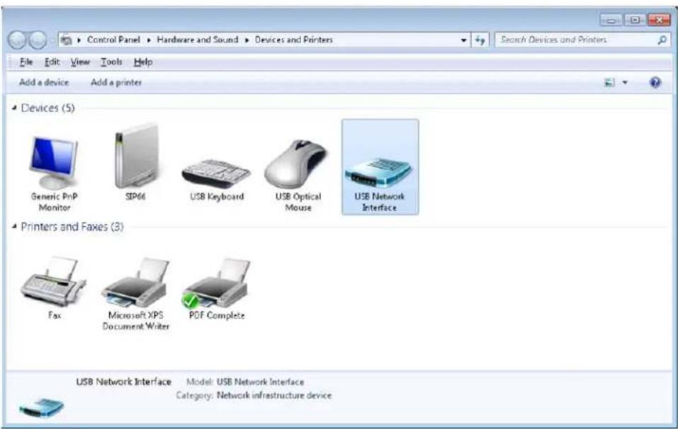
- Select the Hardware tab.
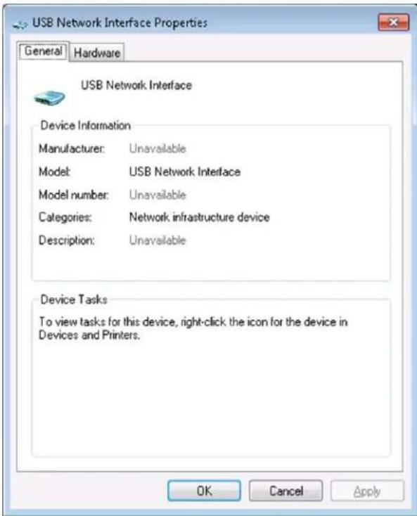
4. Click Properties.
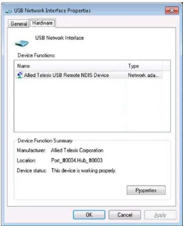
5. Click Change Settings.
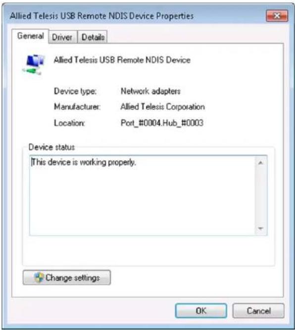
- Select the Driver tab.
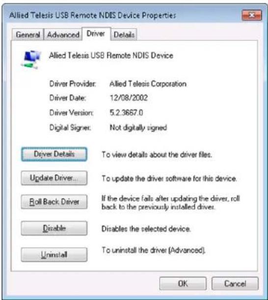
- Click Unistall, then OK in the Confirm Device Unistall window.
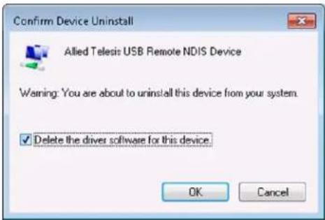
- Close the USB Remote NDIS Device Properties window.
- Disconnect the USB cable.
B.2 Installing the Windows 7 Native Driver
This section describes the steps to instruct Windows 7 to use its universal NDIS driver to control the USB interface associated with the Allied Telesis iMG.
- From the Start menu, select Devices and Printers.
- Under Unspecified, right-click on USB Network Interface and select Properties.
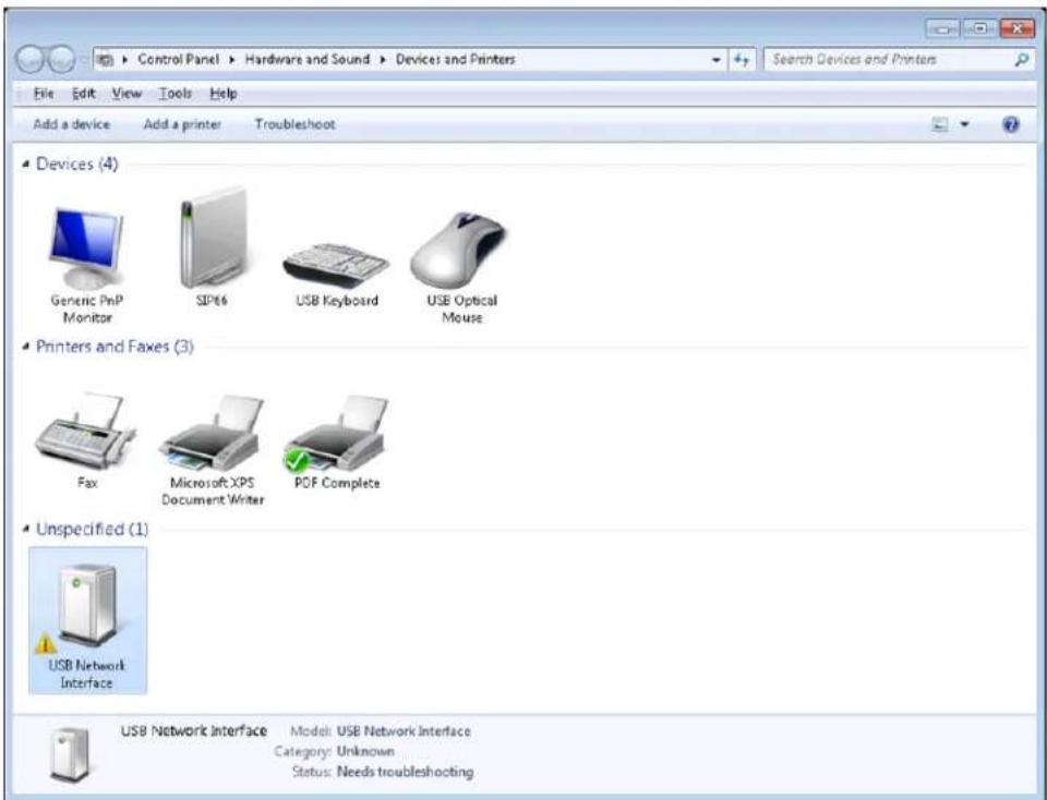
- Select the Hardware tab.
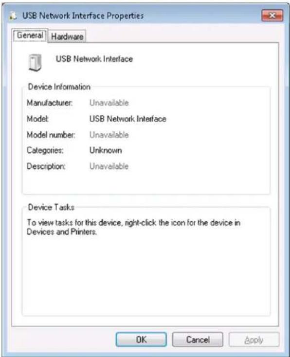
- Select Properties.
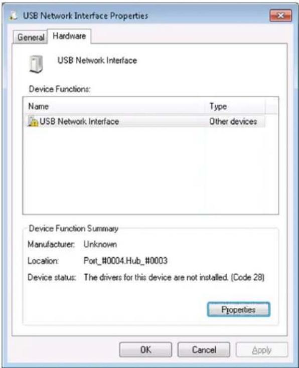
- Select Change Settings.
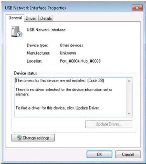
6. Select the Driver tab, then select Update Driver.
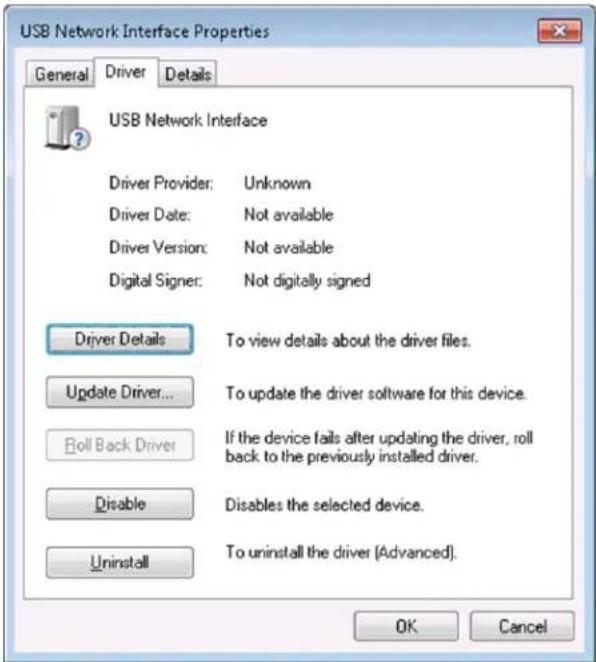
7. Select Browse my computer for driver software.
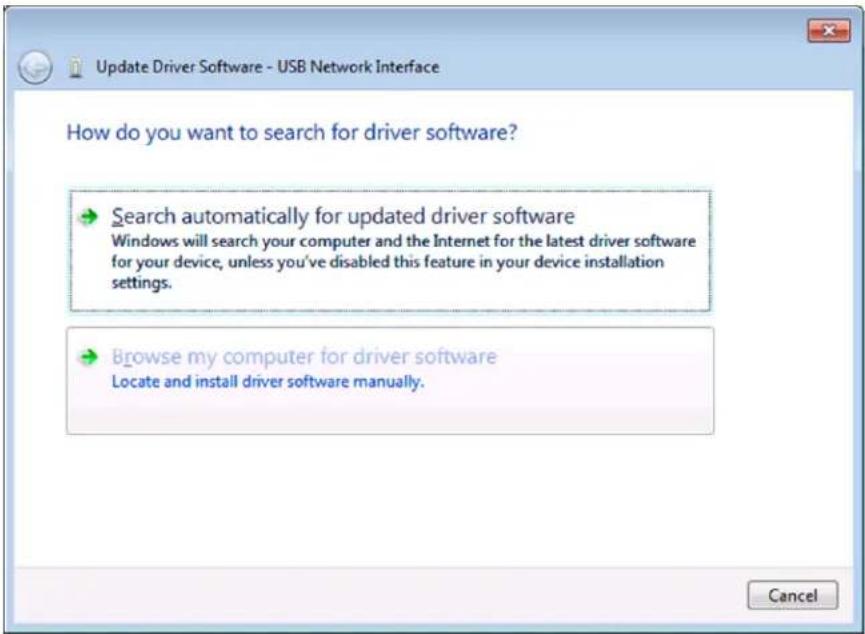
- Select Let me pick a list of device drivers on my computer.
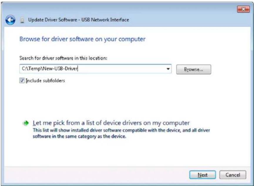
- Select Network Adapters, then click Next.
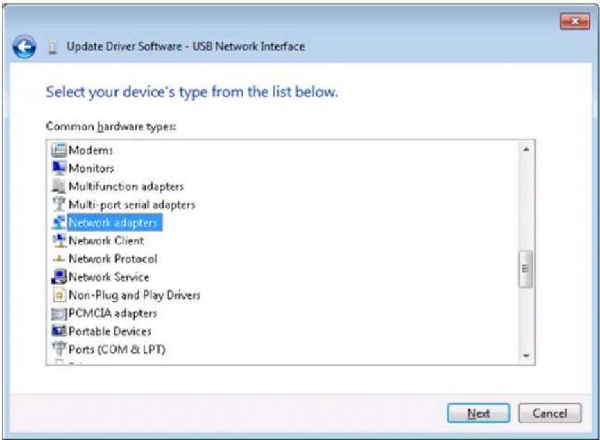
- Under Manufacturer, select Microsoft Corporation. Under Network Adapter, select Remote NDIS Compatible Device.
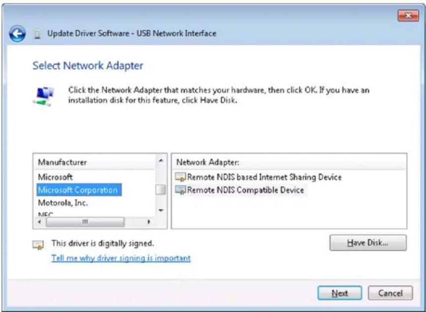
- Click Next.
- In the Update Driver Warning window, click Yes.
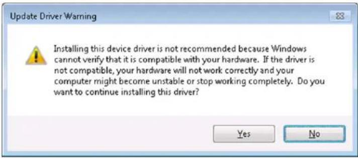
- Wait for Windows to install the driver. Click Close when you receive the confirmation that the driver software has updated successfully.
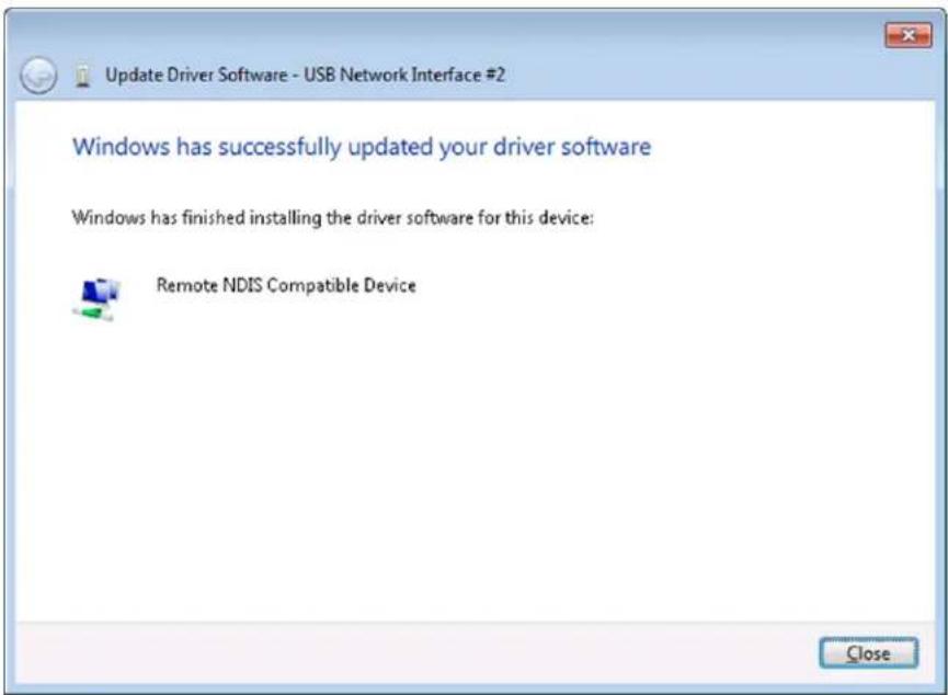
- The new USB device will be displayed in the Devices list
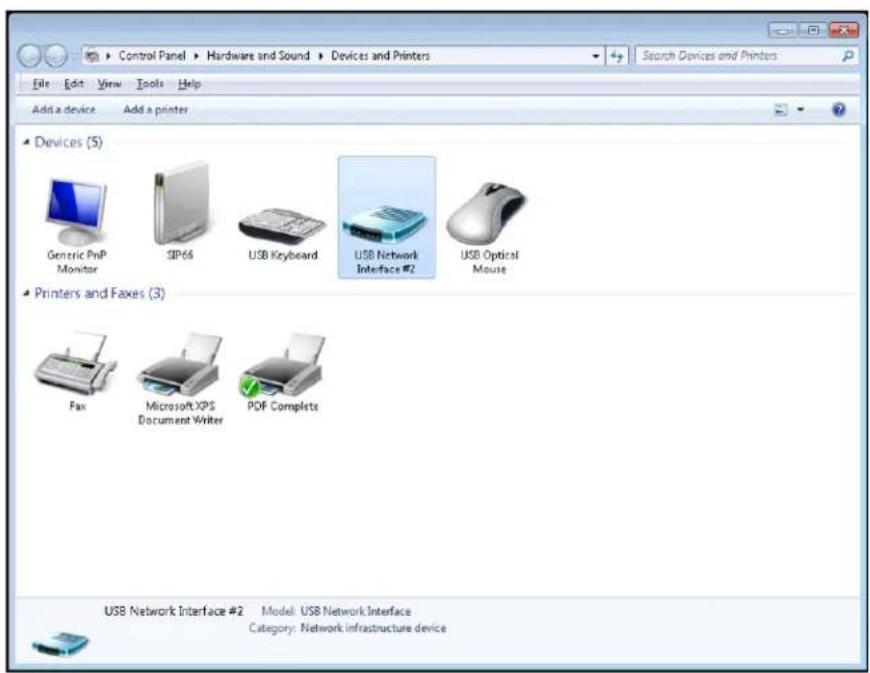
B.3 Disabling IPv6 on the USB Interface
The final steps for Windows 7 to communicate to an iMG USB interface consist of disabling IPv6 support on the USB connection.
- Open the Control Panel.
- Select the Network and Sharing Center.
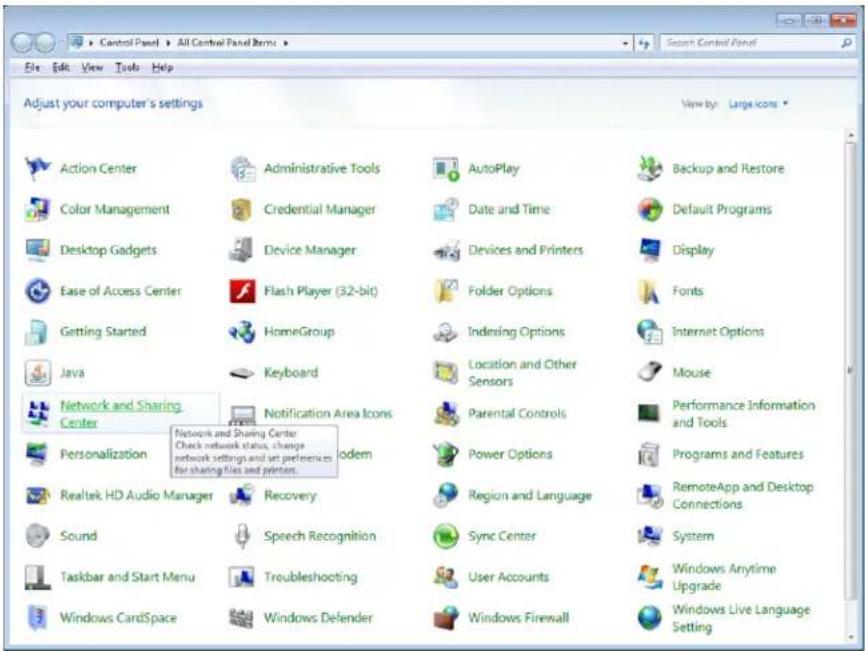
- Select the Local Area Connection corresponding to the USB/iMG interface.
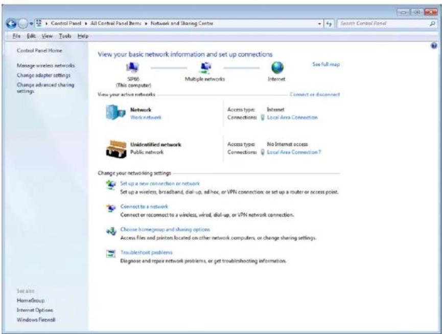
- Select Properties.
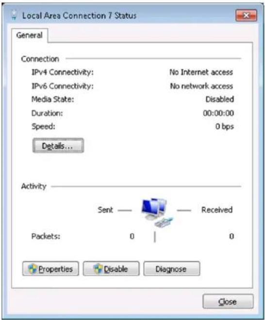
- Deselect Internet Protocol Version 6 (TCP/IPV6), then click OK.
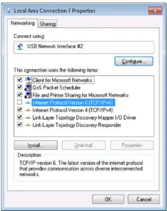
- Unplug the USB cable and then plug it back again to get the valid IPv4 address.
- Preface
- I Introduction
- I.I Purpose of this manual
- II Intended audience
- III How this Document is Organized
- III.1 Sections
- II Document Issue
- IV Allied Telesis Gateway Family Feature Summary
- IV.I IEEE 802.IQ VLAN SUPPORT AND IP ROUTING
- IV.II QoS
- IV.III PORT RATE LIMITING
- IV.IV ROUTING
- IV.V NAT AND FIREWALL
- IV.VI VOICE OVER IP (VOIP)
- IV.VII VIDEO STREAMING
- IV.VIII MANAGEMENT AND CONFIGURATION
- IV.IX IPv6
- IV.X WIRELESS
- V Model Gateways Supported
- VI Reason for Update
- VII Service and Support
- Table of Contents
- Preface 3
- I Setting up the Gateway---- 16
- Routing----146
- Switching- 206
- Multicast Applications---- 304
- Access and Security 329
- Network Management 368
- Simple Network Management Protocol (SNMP) 417
- TR69 Configuration 437
- Voice Management 450
- Voice Service and Protocols 450
- Voice Service Configuration for the iMG 462
- Command Reference 465
- Configuring Voice Applications on Device and Ports 528
- Configuring Dial Peers 593
- Using the GUI Application---- 603
- Overview----603
- Sample Command Sequences 610
- Appendix A: Command List 618
- Appendix B: Windows 7 Drivers 627
- Setting up the Gateway
- I.1 Getting Started
- I.I.I Introduction
- How to Access the Product
- I.1.3 TR-069 Management and Scope of Control for the Management Interfaces
- I.1.4 The Command Interface (CLI)
- I.1.4.1 Getting Help
- I.1.4.2 Command Abbreviations
- I.1.4.3 Viewing a List of Valid Parameters
- I.1.4.4 Example
- I.1.4.5 Examples (clock timezone command)
- I.1.4.6 Completing Keywords
- I.1.4.7 Examples
- I.1.4.8 Moving the Cursor around Input Text (Home and End Keys)
- I.1.4.9 Viewing Command Error Messages
- How to Work with Command Modes
- I.1.5.1 User Exec mode
- I.1.5.2 Privileged Exec Mode
- I.1.5.3 Global Configuration mode
- I.1.5.4 Lower-level configuration modes
- I.1.5.5 Returning to higher-level modes
- I.1.5.6 Examples
- I.1.5.7 Entering Privileged Exec Commands When in a Configuration Mode
- I.1.5.8 Main Command Modes Summary
- I.1.6 How to See the Current Configuration (running-config)
- I.1.7 Default Settings
- I.1.8 The Default Configuration
- I.1.9 Defining a User/Password
- I.I.10 How to Set an IP Address on VLAN I
- Enter the IP address and mask
- I.I.II How to Save and Boot from the Current Configuration
- I.I.II.I How to Save the Running Configuration to the current boot file (startup-config)
- I.I.11.2 How to Create and Use a New Configuration File
- I.I.I1.3 Example
- I.I.11.4 Example
- I.1.12 How to Return to the Factory Defaults
- Completely restore defaults
- I.I.13 Recovery of Single Image (iMG1400)
- I.I.14 How to See System Information
- I.I.14.1 Viewing Overall System Information
- I.I.15 How to Set System Parameters
- I.I.15.1 How to Change the Telnet Session Timeout
- I.1.15.2 Examples
- I.I.15.3 How to Name the Device
- I.1.15.4 Removing the name
- I.I.16 How to Set the Time and Date
- I.I.16.1 How to Show Current Settings
- I.I.16.2 How to Set the Time and Date
- I.1.16.3 How to Set the Timezone
- I.I.16.4 How to Configure Summer-time
- I.1.16.5 How to Configure Summer-time
- I.I.17 How to Add and Remove Users
- I.I.17.1 Adding users
- I.1.17.2 Removing users
- I.1.17.3 Displaying users
- I.1.18 How to Undo Settings and Restore Parameters to Defaults (no option)
- I.1.19 How to Upgrade the Firmware
- I.1.20 How to configure Wireless
- Commands Available in each Mode
- I.1.21.3 Global Configuration Mode
- I.2 Command Syntax Conventions in this Software Reference
- Start-up Sequence
- Setting up the Gateway CLI Navigation Commands
- I.4 CLI Navigation Commands
- CLI Navigation Commands
- CONFIGURE TERMINAL
- DISABLE (PRIVILEGED EXEC MODE)
- DO
- Note NA
- ENABLE (PRIVILEGED EXEC MODE)
- END
- EXIT
- HELP
- SHOW HISTORY
- User Access Commands
- User Access Commands
- ENABLE PASSWORD
- Syntax
- Description
- Options
- Note
- EXEC-TIMEOUT
- SERVICE HTTP
- SERVICE SSH
- SERVICE TELNET
- SHOW HTTP
- SHOW EXEC-TIMEOUT
- Example
- SHOW LINE
- SHOW SECURITY-PASSWORD USER
- SHOW SSH
- SHOW SSH SERVER
- SHOW TELNET
- TERMINAL LENGTH
- USERNAME
- I.6 Creating and Managing Configuration Files
- Introduction
- Software Updates from TFTP server
- Listing Configuration Files
- Creating and Using Configuration Files
- Creating a configuration file
- Specifying the start-up configuration script
- Working with configuration files
- The configuration file fallback order
- Copying Files To and From Your Device
- URL syntax
- Copying files
- I.6.11.1 Copying with Trivial File Transfer Protocol (TFTP)
- File Management Commands
- File Management Commands
- BOOT CONFIG-FILE
- BOOT DEFAULT BUTTON
- BOOT SYSTEM
- BOOT SYSTEM RECOVERY CRC
- Release 4.2
- BOOT SYSTEM RECOVERY FILENAME
- BOOT SYSTEM RECOVERY SERVER
- COPY
- COPY RUNNING-CONFIG
- COPY STARTUP-CONFIG
- DELETE
- DIR
- ENABLE DEFAULT BUTTON CONFIGURATION
- ERASE STARTUP-CONFIG
- MOVE
- SHOW BOOT
- SHOW FILE
- SHOW RUNNING-CONFIG
- Feature File Management Commands
- Mode All command modes
- Release 4.1
- Options NA
- SHOW VERSION
- System Configuration and Monitoring Commands
- System Configuration and Monitoring Commands
- CLOCK SET
- CLOCK SUMMER-TIME
- CLOCK TIMEZONE
- HOSTNAME
- PSU-MANAGEMENT
- Setting up the Gateway System Configuration and Monitoring Commands
- SHOW CLOCK
- SHOW CPU
- SHOW MEMORY SHARED
- SHOW SYSTEM
- SHOW SYSTEM PSU
- SHOW TECH-SUPPORT
- Software Update
- Introduction
- Software Update Command List
- SHOW SWUPDATE
- SWUPDATE
- SWUPDATE NOW
- Debugging and Logging
- Introduction
- Debugging
- Logging
- Example - Creating a Log Stream that includes igmp and is displayed at the terminal monitor
- I.10.3.2 Logging of Executed Commands (Info level)
- Duplicate Logs Suppressed
- I.10.3.4 Logging of voip Subsystem
- Host log
- I.11 Debugging and Logging Commands
- I.II.1 Debugging and Logging Commands
- CLEAR LOG
- DEBUG
- LOG HOST
- SHOW LOG
- SHOW LOG CONFIG
- Interfaces
- PPPoE
- HPNA
- Interface Commands
- Interface Commands
- INTERFACE PORT
- INTERFACE CATV
- INTERFACE VLAN
- SHOW CATV
- SHOW CATV DIAGNOSTICS
- SHOW INTERFACE
- SHOW INTERFACE BRIEF
- SHOW INTERFACE STATUS
- SHOW INTERFACE SWITCHPORT
- SHUTDOWN (CONFIG-IF-CATV)
- Example Configuration
- Routing
- Introduction
- Assigning an IP Address
- Static IP addresses
- DHCP dynamic addresses
- Address Resolution Protocol (ARP)
- Domain Name System (DNS)
- Domain name parts
- Server hierarchy
- DNS Client
- Dynamic DNS (ddns)
- DHCP options
- Internet Control Message Protocol (ICMP)
- Checking IP Connections (ping and traceroute)
- Ping
- Traceroute
- Multiple IP Addresses on a Subinterface (subvlan)
- Overview
- Creating a sub-vlan
- Features that use subvlans
- Layer 3 Routing - iMG
- Layer 3 Routing Command List
- ADD PROVIDER
- ADD URL
- HTTP
- IP ADDRESS
- Mode
- IP DDNS UPDATE HOSTNAME
- IP DDNS UPDATE METHOD
- IP DOMAIN-NAME
- IP NAME-SERVER (IPV4)
- IP ROUTE
- PING (IPV4)
- REMOVE PROVIDER
- REMOVE URL
- SHOW HOSTS
- SHOW IP DDNS
- SHOW IP DOMAIN-LIST
- SHOW IP DOMAIN-NAME
- SHOW IP INTERFACE BRIEF
- SHOW IP NAME-SERVER (IPV4)
- SHOW IP ROUTE
- SHOW IP SOCKETS
- TRACEROUTE
- IPv6
- Overview
- IPv6 Addresses and Prefixes
- Address Types
- unicast addresses
- Multicast addresses
- Anycast addresses
- IPv6 Headers
- Basic IPv6 Header Structure
- Extension Headers
- Routing IPv6
- The Internet Control Message Protocol (ICMPv6)
- Neighbor Discovery
- Stateless Address Autoconfiguration (SLAAC)
- On the Router or Host
- On the Host
- IPv6 Routing
- Integration of IPv4 and IPv6
- Enabling IPv6 on the iMG
- Enabling IPv6
- IPv6 Stateless Address Autoconfiguration (SLAAC)
- IPv6 Link-local Addresses
- IPv6 and IPv4 on the iMG
- IPv6 Command List
- IPV6 ADDRESS (CONFIG-IF)
- IPV6 ENABLE (CONFIG-IF)
- IPV6 FORWARDING (CONFIG)
- IP NAME-SERVER (CONFIG) - IPV6
- IPV6 ND DAD-ATTEMPTS (CONFIG-IF)
- IPV6 ND MANAGED-CONFIG-FLAG (CONFIG-IF)
- Feature IPv6 Commands
- Mode Interface Mode
- IPV6 ND MINIMUM-RA-INTERVAL (CONFIG-IF)
- IPV6 ND OTHER-CONFIG-FLAG (CONFIG-IF)
- IPV6 ND RA-INTERVAL (CONFIG-IF)
- IPV6 ND RS-ATTEMPTS (CONFIG-IF)
- IPV6 ND RS-DELAY (CONFIG-IF)
- IPV6 ND RS-INTERVAL (CONFIG-IF)
- IPV6 ND SUPPRESS-RA (CONFIG-IF)
- PING IPV6
- SHOW IP NAME-SERVER (IPV6)
- SHOW IPV6 FORWARDING
- SHOW IPV6 GENERAL-PREFIX
- SHOW IPV6 INTERFACE BRIEF
- SHOW IPV6 INTERFACE VERBOSE
- SHOW IPV6 NEIGHBORS
- SHOW IPV6 ROUTE
- TRACEROUTE IPV6
- Switching
- Physical Layer
- Port attributes
- Port Numbering
- Support for using Copper interface as WAN interface
- SFP pluggable models compatibility
- Using Port ranges
- Activating and Deactivating Switch Ports
- Autonegotiation
- Duplex mode
- Speed options
- Port Mirroring
- Quality of Service
- Key capabilities are:
- Loop Protection
- Switching Physical Layer
- HPNA Interface
- Wireless Interface
- The Layer 2 Switching Process
- The Ingress Rules
- Access Mode
- Trunk Mode
- The Learning Process
- The Forwarding Process
- The Egress Rules
- Layer 2 Filtering
- Ingress Filtering
- IGMP Snooping
- Switching Command List
- CLEAR MAC ADDRESS-TABLE DYNAMIC
- CLEAR MAC ADDRESS-TABLE STATIC
- CLEAR PORT COUNTER
- DUPLEX
- FLOWCONTROL
- JUMBO-FRAME
- LOOP-PROTECTION ACTION LINK-DOWN
- LOOP-PROTECTION LOOP-DETECT
- LOOP-PROTECTION TIMEOUT
- MAC ADDRESS-TABLE ACQUIRE
- MAC ADDRESS-TABLE AGEING-TIME
- MIRROR INTERFACE
- PLATFORM VLAN-STACKING-TPID
- SHOW MAC ADDRESS-TABLE
- SHOW MIRROR
- SHOW PLATFORM
- SHOW PLATFORM PORT COUNTERS
- Note N/A
- SHOW STORM-CONTROL
- SPEED
- STORM-CONTROL
- SWITCHPORT BLOCK
- VLAN - General
- Introduction
- Virtual LANs (VLANs)
- Configuring VLANs
- Defaults
- VLAN names
- Access mode
- Trunk mode
- VLANs
- VLAN Double Tagging (VLAN Stacking)
- How Double-Tagged VLANs Work
- VLAN Rules for Double Tagging
- Restrictions when using Double-Tagged VLANs
- Configuring Double-Tagged VLANs
- VLAN - iMG
- VLAN Commands
- SHOW VLAN
- SWITCHPORT ACCESS VLAN
- SWITCHPORT MODE ACCESS
- SWITCHPORT TRUNK ALLOWED VLAN
- Switching VLAN - iMG
- SWITCHPORT TRUNK NATIVE VLAN
- SWITCHPORT VLAN-STACKING (DOUBLE TAGGING)
- VLAN
- VLAN DATABASE
- PPPoE
- PPPoE Protocol Components
- Automatically populating routing table and DNS server table
- Activating the Feature
- PPPoE Commands
- PPP AUTHENTICATION
- PPP IPCP DEFAULT ROUTE
- PPP IPCP DNS REQUEST
- PPP SENT-USERNAME
- PPPOE ENABLE
- HPNA
- HPNA Commands
- INTERFACE HPNA1.0.1
- CLEAR HPNA COUNTERS
- SHOW HPNA COUNTERS
- SHOW HPNA STATIONS
- SHOW TEST
- TEST INTERFACE HPNA1.0.1
- Wireless
- Wireless Commands
- AUTHENTICATION KEY-MANAGEMENT
- Release 4.3.3
- AUTHENTICATION OPEN
- CHANNEL
- CLIENT-ISOLATION
- CONFIG-RESET
- Switching Wireless
- DENY
- DOT11 SSID
- GUEST-MODE
- INTERFACE DOT11RADIO1.0.1
- MAX-ASSOCIATION
- PERMIT
- PROTOCOL-FAMILY
- SHOW DOT 11 ASSOCIATIONS
- SHOW DOT11 BSSID
- SHOW INTERFACE DOT11RADIO1.0.1
- SHOW INTERFACE DOT11RADIO1.0.1 STATUS
- SHOW WIRELESS COUNTRY SUPPORTED
- SHUTDOWN
- SSID-NAME
- Release 4.3
- WORLD-MODE DOT11D COUNTRY-CODE
- WPA-PSK
- Multicast Applications
- IGMP Snooping Introduction and Configuration
- Multicasting overview
- Multicast Group addresses
- IGMP protocol
- Multicast MAC addresses
- IGMP snooping Functional Overview
- IGMP Snooping on iMG
- IGMP Snoop Only Mode
- Join operation
- Leave operation
- Expiring of a Multicast entry
- IGMP Proxy Mode
- Join operation
- Leave operation
- Expiring of a Multicast entry
- IGMP Proxy Routed Mode (Multicast Acceleration)
- Multicast Command List
- IP IGMP LAST-MEMBER-QUERY-INTERVAL
- IP IGMP LIMIT
- IP IGMP PROXY-SERVICE
- Multicast Applications IGMP Snooping on iMG
- IP IGMP PROXY-SERVICE (INTERFACE LEVEL)
- IP IGMP QUERY-INTERVAL
- IP IGMP QUERY-MAX-RESPONSE-TIME
- IP IGMP ROBUSTNESS-VARIABLE
- IP IGMP SNOOPING
- Feature IGMP Multicast Commands
- Mode Interface Config (VLANs)
- IP IGMP SNOOPING FAST-LEAVE
- IP IGMP VERSION
- SHOW IP IGMP
- SHOW IP IGMP GROUPS
- Access and Security
- Quality of Service Model
- Address management
- Rate limiting support
- Quality of Service Classification
- 802.1p traffic priority
- Differentiated services code point (DSCP)
- QoS Command List
- EGRESS-RATE-LIMIT
- INGRESS-RATE-LIMIT
- MLS QOS COS
- MLS QOS MAP COS-QUEUE
- MLS QOS MAP PREMARK-DSCP TO NEW-QUEUE
- Feature QoS Commands
- MLS QOS TRUST COS
- MLS QOS TRUST DSCP
- SHOW MLS QOS INTERFACE
- SHOW MLS QOS MAPS COS-QUEUE
- SHOW MLS QOS MAPS PREMARK-DSCP
- Secure Shell Protocol
- Introduction
- Configuring the SSH Server
- Enabling the Server
- SSH Command List
- DEBUG SSHD
- Access and Security Secure Shell Protocol
- Feature SSH Commands
- Mode Global Configuration Mode
- Security (Trigger, Firewall, Access Control List, Logging)
- Overview
- Triggers
- Firewall
- Port Filters (using the GUI)
- Logging Intrusion Attempts
- Access Control List (ACL)
- Overview
- Extended Access Lists
- IPv6 Access Lists
- Protected Ports
- Security Command List
- ACCESS-GROUP
- ACCESS-LIST
- DEBUG ACCESS LEVEL
- FIREWALL ENABLE (CONFIG-IF)
- Feature Security Commands
- IP FIREWALL TRIGGER (CONFIG-IF)
- IPV6 ACCESS-LIST EXTENDED
- IPV6 TRAFFIC-FILTER
- PROTECTED
- SHOW ACCESS-GROUP
- SHOW ACCESS-LIST
- SHOW IP FIREWALL STATUS
- SHOW IPV6 ACCESS-LIST EXTENDED
- SHOW IPV6 TRAFFIC-FILTER
- Network Management
- Network Address Translation (NAT)
- Introduction
- NAT on the iMG
- NAT Command List
- IP NAT ENABLE
- IP NAT PORTMAP
- SHOW IP NAT
- Network Time Protocol (NTP)
- Introduction
- NTP on the iMG
- NTP Command List
- NTP CONF
- NTP PEER
- Network Management Network Time Protocol (NTP)
- NTP SYNC
- SHOW NTP ASSOCIATIONS
- SHOW NTP STATUS
- Dynamic Host Configuration Protocol (DHCP)
- BOOTP
- DHCP
- Configuring the DHCP Server
- Access the Pool
- Access the Pool for IPV6
- Define the Subnet
- Define the Range
- Set the Lease
- Set the Options
- Configuring the DHCP Client
- DHCP Command list
- DNS-SERVER
- DNS-SERVER (IPV6)
- or
- DOMAIN-NAME
- DOMAIN-NAME (IPV6)
- FILENAME
- HOST
- Network Management Dynamic Host Configuration Protocol (DHCP)
- IP ADDRESS DHCP
- IP DHCP CLIENT BROADCAST-FLAG
- IP DHCP CLIENT CLASS-ID
- IP DHCP CLIENT CLIENT-ID
- IP DHCP CLIENT REQUEST
- IP DHCP POOL
- IP DHCP SERVER INTERFACE
- IPV6 DHCP CLIENT PD
- IPV6 DHCP CLIENT REQUEST
- IPV6 DHCP POOL
- LEASE
- OPTION
- RANGE
- SERVICE DHCP-SERVER
- SHOW COUNTER DHCP-CLIENT
- SHOW COUNTER DHCP-SERVER
- SHOW DHCP LEASE
- SHOW IP DHCP BINDING
- SHOW IP DHCP POOL
- SHOW IP DHCP SERVER SUMMARY
- SHOW IPV6 DHCP INTERFACE
- SUBNET-MASK
- NETWORK (DHCP)
- Simple Network Management Protocol (SNMP)
- Introduction
- Network Management Framework
- Structure of Management Information
- Names
- Instances
- Syntax
- Access
- Status
- Description
- The SNMP Protocol
- SNMP Versions
- SNMP Messages
- Polling versus Event Notification
- Message Format for SNMPv1 and SNMPv2c
- SNMP Communities (Version v1 and v2c)
- SNMPv1 and SNMPv2c
- SNMP MIB Views for SNMPv1 and SNMPv2c
- SNMP Communities
- Defining Management Stations within Communities
- Configuration Example (SNMPv1 and v2)
- To configure SNMP
- Enable the SNMP agent.
- Object ID (OID) Numbers for iMG Models
- The following OIDs are registered for the iMG Models.SNMP Command List
- SHOW RUNNING-CONFIG SNMP
- SHOW SNMP-SERVER
- SHOW SNMP-SERVER COMMUNITY
- SHOW SNMP-SERVER TRAPS
- Network Management Simple Network Management Protocol (SNMP)
- SNMP-SERVER IP
- SNMP-SERVER COMMUNITY
- SNMP-SERVER CONTACT
- SNMP-SERVER ENABLE TRAPS LINK-STATUS
- SNMP-SERVER HOST
- SNMP-SERVER LOCATION
- SNMP-SERVER SYSTEM-SHUTDOWN
- TR69 Configuration
- Introduction
- TR69 Command List
- SHOW TR69-CLIENT
- TR69-CLIENT ACS-AUTHENTICATION
- TR69-CLIENT ACS-URL
- TR69-CLIENT BIND SOURCE-INTERFACE
- TR69-CLIENT INFORM
- TR69-CLIENT REQUEST-AUTHENTICATION
- Universal Plug and Play
- Introduction
- UPnP on the iMG
- UPnP Command List
- IP UPNP NETWORK ENABLE
- SHOW IP UPNP
- Voice Management
- Voice Service and Protocols
- Introduction
- MGCP
- MGCP Endpoints
- MGCP Wildcard
- MGCP Heartbeat
- MGCP Call Agent Failover
- SIP
- Introduction
- Direct Signaling
- Registration / Proxy Signaling
- SIP Digit Map
- Voice Management Voice Service and Protocols
- SIP Proxy and SIP Registrar (with Failover)
- Services (Common)
- Dial Peers
- DTMF Relay
- Telecom Tone Management
- Media Format
- FAX/Modem Relay
- RTP Media Management
- Distinctive Ringing
- Prefix Replacement
- Voice Quality Management
- Voice Service Configuration for the iMG
- Overview
- Basic Command Sequences for Provisioning
- Command Reference
- Voice Service Logging
- Voice Service Command List (config-voi-serv)
- CPTONE (CONFIG-VOI-SERV)
- DTMF-RELAY VOIP (CONFIG-VOI-SERV)
- FAX PROTOCOLT38 (CONFIG-VOI-SERV)
- IP RTP PRECEDENCE (CONFIG-VOI-SERV)
- IP SIGNALING PRECEDENCE (CONFIG-VOI-SERV)
- RTP BEHAVIOR DISCARD-WHEN-REMOTE-UNKNOWN (CONFIG-VOI-SERV)
- RTP BEHAVIOR DISCARD-WHEN-SOURCE-UNKNOWN (CONFIG-VOI-SERV)
- RTCP (CONFIG-VOI-SERV)
- RTP PAYLOAD-TYPE (CONFIG-VOI-SERV)
- SHUTDOWN (CONFIG-VOI-SERV)
- TONE INCOMING (CONFIG-VOI-SRV)
- Enable/Disable MGCP Command List (config-serv-mgcp)
- BIND (CONFIG-SERV-MGCP)
- CALL SERVICE RESTART (CONFIG-SERV-MGCP)
- CALL SERVICE (CONFIG-SERV-MGCP)
- LISTEN-PORT (CONFIG-SERV-MGCP)
- Enable/Disable SIP Command List (config-serv-sip)
- BIND (CONFIG-SERV-SIP)
- CALL SERVICE RESTART (CONFIG-SERV-SIP)
- CALL SERVICE (CONFIG-SERV-SIP)
- HAIRPIN (CONFIG-SERV-SIP)
- LISTEN-PORT (CONFIG-SERV-SIP)
- LOCALHOST (CONFIG-SERV-SIP)
- Configure MGCP Protocol Command List (config-mgcp)
- BACKUP-CALL-AGENT (CONFIG-MGCP)
- Voice Management Command Reference
- BEHAVIOR RSIP-RANGE (CONFIG-MGCP)
- CALL-AGENT (CONFIG-MGCP)
- DOMAIN (CONFIG-MGCP)
- ENDPOINT OFFSET (CONFIG-MGCP)
- PACKAGE-CAPABILITY LCS-PACKAGE (CONFIG-MGCP)
- PERSISTENT (CONFIG-MGCP)
- REQUEST RETRIES (CONFIG-MGCP)
- REQUEST TIMEOUT (CONFIG-MGCP)
- RTP PAYLOAD-TYPE (CONFIG-MGCP)
- SHOW MGCP
- Configure SIP Protocol Command List (config-sip-ua)
- AUTHENTICATION METHOD (CONFIG-SIP-UA)
- BEHAVIOR DISABLE-URL-MATCHING
- BEHAVIOR HOOK-FLASH (CONFIG-SIP-UA)
- Source
- BEHAVIOR SOFTSWITCH (CONFIG-SIP-UA)
- MAP ALERTINFO (CONFIG-SIP-UA)
- REL1XX
- SHOW SIP SERVICE
- SHOW SIP-UA
- SHOW SIP-UA MAP ALERTINFO
- SIP-SERVER (CONFIG-SIP-UA)
- SUBSCRIBE MESSAGE-SUMMARY
- Configuring Voice Prefix Replacement (config-voi-trans-rule)
- VOICE TRANSLATION-RULE
- Example TThe
- RULE
- SHOW VOICE TRANSLATION-RULE
- Configuring Voice Applications on Device and Ports
- Voice Management Configuring Voice Applications on Device and Ports
- Access Codes (Supplementary Services) Command list (config-voipapp-fac)
- CALL FORWARD ALL (CONFIG-VOIPAPP-FAC)
- CALL FORWARD ALL CANCEL (CONFIG-VOIPAPP-FAC)
- CALL FORWARD BUSY (CONFIG-VOIPAPP-FAC)
- Feature Voice Commands
- CALL FORWARD BUSY CANCEL (CONFIG-VOIPAPP-FAC)
- CALL FORWARD NO-ANSWER (CONFIG-VOIPAPP-FAC)
- CALL FORWARD NO-ANSWER CANCEL (CONFIG-VOIPAPP-FAC)
- CALL-WAITING (CONFIG-VOIPAPP-FAC)
- CALL-WAITING CANCEL (CONFIG-VOIPAPP-FAC)
- CALLER-ID BLOCK OVERRIDE OFF (CONFIG-VOIPAPP-FAC)
- CALLER-ID BLOCK OVERRIDE ON (CONFIG-VOIPAPP-FAC)
- CONFERENCE (CONFIG-VOIPAPP-FAC)
- PER-CALL CALL-WAITING (CONFIG-VOIPAPP-FAC)
- PER-CALL CALL-WAITING CANCEL (CONFIG-VOIPAPP-FAC)
- PREFIX (CONFIG-VOIPAPP-FAC)
- SHOW VOIPAPP
- SUFFIX (CONFIG-VOIPAPP-FAC)
- TRANSFER BLIND (CONFIG-VOIPAPP-FAC)
- TRANSFER CONSULT (CONFIG-VOIPAPP-FAC)
- WARMLINE (CONFIG-VOIPAPP-FAC)
- WARMLINE CANCEL (CONFIG-VOIPAPP-FAC)
- Supplementary Service Command list (voipapp-suppl-serv-port)
- CALL FORWARD BUSY (CONFIG-VOIPAPP-SUPPL-SERV-PORT)
- CALL FORWARD NOAN (CONFIG-VOIPAPP-SUPPL-SERV-PORT)
- CONFERENCE (CONFIG-VOIPAPP-SUPPL-SERV-PORT)
- HOLD-RESUME (CONFIG-VOIPAPP-SUPPL-SERV-PORT)
- TRANSFER-MODE (CONFIG-VOIPAPP-SUPPL-SERV-PORT)
- WARMLINE (CONFIG-VOIPAPP-SUPPL-SERV-PORT)
- WARMLINE DIGITS (CONFIG-VOIPAPP-SUPPL-SERV-PORT)
- WARMLINE TIMEOUT (CONFIG-VOIPAPP-SUPPL-SERV-PORT)
- Endpoint Command List (config-voice-port)
- CALL-WAITING (CONFIG-VOICE-PORT)
- CALLER-ID ALERTING (CONFIG-VOICE-PORT)
- CALLER-ID BLOCK (CONFIG-VOICE-PORT)
- CALLER-ID (CONFIG-VOICE-PORT)
- CALLER-ID MODE (CONFIG-VOICE-PORT)
- CALLER-ID SIGNAL (CONFIG-VOICE-PORT)
- CALLER-ID STANDARD (CONFIG-VOICE-PORT)
- DIAL-TYPE (CONFIG-VOICE-PORT)
- DISCONNECT-SUPERVISION OSI
- ECHO-CANCEL (CONFIG-VOICE-PORT)
- MWI (CONFIG-VOICE-PORT)
- INPUT GAIN (CONFIG-VOICE-PORT)
- OUTPUT ATTENUATION (CONFIG-VOICE-PORT)
- PLAYOUT-DELAY (CONFIG-VOICE-PORT)
- PLAYOUT-DELAY MODE (CONFIG-VOICE-PORT)
- SHOW VOICE PORT
- TIMING HOOKFLASH-INPUT
- TIMING OFFHOOK-INPUT
- TIMING ONHOOK-INPUT
- TIMEOUTS INITIAL
- TIMEOUTS INTERDIGIT
- TIMEOUTS RINGING
- VAD (CONFIG-VOICE-PORT)
- Configuring Codecs Command List
- CODEC PREFERENCE (CONFIG-VOICE-CLASS)
- Source NA
- Voice Diagnostic Command List
- TEST VOICE PORT
- Configuring Dial Peers
- Configuring Dial Peers Command List (config-dial-peer)
- AUTHENTICATION USERNAME (CONFIG-DIAL-PEER)
- DESTINATION-PATTERN (CONFIG-DIAL-PEER)
- DIAL-PEER (CONFIG-DIAL-PEER)
- DOMAIN (CONFIG-DIAL-PEER)
- REGISTRATION-NAME (CONFIG-DIAL-PEER)
- SESSION TARGET (CONFIG DIAL-PEER)
- SHOW DIAL-PEER VOICE
- TRANSLATE-OUTGOING (CONFIG-DIAL-PEER)
- Using the GUI Application
- Overview
- Introduction
- Allied Telesis®
- Menu Levels
- Split Management
- Using the GUI Application Split Management
- Sample Command Sequences
- Introduction
- Configuring the iMG (except for Voice Service)
- Configuring Voice Service (SIP)
- Configuring Voice Service (MGCP)
- IPv6 Configuration
- Appendix A: Command List
- Appendix B: Windows 7 Drivers
- I Uninstalling the Existing Driver
- Click Properties.
- Click Change Settings.
- B.2 Installing the Windows 7 Native Driver
- Select the Driver tab, then select Update Driver.
- Select Browse my computer for driver software.
- B.3 Disabling IPv6 on the USB Interface
Brand : Allied Telesis
Model : iMG1405
Category : Router