ISDN-Controller T1 - ISDN Controller AVM - Free user manual and instructions
Find the device manual for free ISDN-Controller T1 AVM in PDF.


| Product Type | ISDN Controller |
| Brand | AVM |
| Model | ISDN-Controller T1 |
| Interface | PCI (typical) |
| ISDN Standard | BRI (Basic Rate Interface) |
| Number of Channels | 2 B + 1 D (2x 64 kbps, 1x 16 kbps) |
| Supported Protocols | DSS1, Euro-ISDN, 1TR6 |
| Connector Type | RJ-45 (S0 bus) |
| Power Supply | Powered via PCI slot (5V DC) |
| Power Consumption | Typically 2.5 W |
| Dimensions (approx.) | 12.5 cm x 6.0 cm x 1.5 cm |
| Weight | 60 g |
| Operating Temperature | 0°C to 50°C |
| Storage Temperature | -20°C to 70°C |
| Operating Humidity | 20% to 80% (non-condensing) |
| Compatible Operating Systems | Windows 95/98/ME, Windows NT 4.0 |
| Main Functions | Voice, data, fax transmission over ISDN; CAPI 2.0 support |
| LED Indicators | Power, Line status |
| Cleaning and Maintenance | Use a soft, dry cloth; avoid liquids and solvents |
| Safety Instructions | Disconnect from power before installation; avoid static discharge |
| Spare Parts and Repairability | Spare parts not available; device is obsolete and not intended for repair |
| Certifications | CE, CTR3 |
| Package Contents | Controller card, driver disk, manual |
Frequently Asked Questions - ISDN-Controller T1 AVM
User questions about ISDN-Controller T1 AVM
0 question about this device. Answer the ones you know or ask your own.
Ask a new question about this device
Download the instructions for your ISDN Controller in PDF format for free! Find your manual ISDN-Controller T1 - AVM and take your electronic device back in hand. On this page are published all the documents necessary for the use of your device. ISDN-Controller T1 by AVM.
USER MANUAL ISDN-Controller T1 AVM
AVM ISDN-Controller T1 Manual
This manual and the software it describes are protected by copyright. The manual and software as presented are the object of a license agreement and may be used only in accordance with the license conditions. The licensee bears all risk in regard to hazards and impairments of quality which may arise in connection with the use of this product.
This manual and the software programs it describes may not be transmitted, reproduced or altered, in whole or in part, in any form, by any means; nor may they be translated into any other natural or computer language. The creation of a backup copy for personal use is excepted. The information hereby made available to the licensee may be communicated to third parties only with the written permission of AVM Berlin.
All software and the manual have been produced with all due care and inspected for correctness in accordance with the best available technology. AVM Berlin disclaims all liability and warranties, whether express or implied, relating to this product's quality, performance or suitability for any particular purpose which deviates from the performance specifications contained in the product description.
AVM Berlin will not be liable for damages arising directly or indirectly from the use of the manual or related software, nor for incidental or consequential damages, except in case of intent or gross negligence. AVM expressly disclaims all liability for loss of or damage to hardware, software or data as a result of direct or indirect errors or destruction and for any costs, including ISDN connection charges, related to the software and manual supplied and due to incorrect installations not performed by AVM itself.
The information contained in this manual and the software it describes are subject to change without notice for the purpose of technical improvement.

Copyright 1998 AVM Berlin. All rights reserved.
Trademarks: AVM and FRITZ! are registered trademarks of AVM Vertriebs KG. Windows is a registered trademark of Microsoft Corporation. All other trademarks are trademarks of their respective owners.
Contents
1 Introduction to the AVM ISDN-Controller T1/T1-B ....7
1.1 The ISDN Network....7
1.1.1 ISDN Line Types ....8
1.1.2 The Primary Rate Interface....8
1.2 The AVM ISDN-Controller T1/T1-B 9
1.3 Package Contents ....11
2 Hardware Installation .... 13
2.1 Installing the PC Interface Card ....14
2.1.1 Installing Several PC Interface Cards ....15
2.2 Connecting the Cable from the PC Interface Card to the AVM ISDN-Controller T1/T1-B 16
2.3 Connecting the Cable from the ISDN-Controller T1 to the NT .....16
2.3.1 Connection to the NTPM (NT with Terminal Board) .....17
2.3.2 Connection to the NTPMKU or NTPMGF (NTs with T-shaped Mounting Element)....18
3 Driver Software Installation.... 19
3.1 MS-DOS Installation ....19
3.1.1 Installing the Driver Software ....20
3.1.2 Loading and Unloading the ISDN-Controller ....21
3.1.3 Installing Additional ISDN-Controllers .....22
3.1.4 Removing the Driver Software ....24
3.2 Windows NT Installation ....24
3.2.1 Installing the Driver Software ....25
3.2.2 Loading and Unloading the ISDN-Controller .....27
3.2.3 Installing Additional ISDN-Controllers 28
3.2.4 Removing the Driver Software ....28
3.3 Novell NetWare 3.x and 4.x Installation....29
3.3.1 Installing the Driver Software as a Stand-Alone CAPI .....29
3.3.1.1 Configuring the ISDN-Controller....31
3.3.1.2 Loading and Unloading the ISDN-Controller......31
3.3.1.3 Installing Additional ISDN-Controllers ....32
3.3.1.4 Removing the ISDN-Controller ....32
3.3.2 Installing the Driver Software as a CAPI.NLM for the Novell CAPI Manager ....33
3.3.2.1 Configuring the ISDN-Controller....35
3.3.2.2 Installing Additional ISDN-Controllers ....36
3.3.2.3 Removing the ISDN-Controller ....36
4 Troubleshooting 39
4.1 The "Power" LED is not lit. 39
4.2 When the ibase driver is loaded, the message "No processors found" appears. 39
4.3 After the ibase driver is loaded, the "System" LED is not lit. .....40
4.4 The "Sync" LED is not lit. 41
4.5 The "D Channel" LED is not lit. 42
5 Hardware Structure of the AVM ISDN-Controller T1/T1-B...... 43
5.1 The ISDN-Controller T1 ....44
5.2 The Link Adapter ....45
5.3 The Power Supply ....46
Appendix A: AVM ISDN-Controller T1/T1-B Package Contents...... 47
Appendix B: Illustrations.... 49
Appendix C: Tables.... 57
Conventions Used in this Manual
Graphical Symbols
This symbol alerts you to situations that can produce critical or irreversible errors if you do not follow instructions carefully.
This symbol points out hints, tips, or helpful information that you should know.
This symbol indicates sidelights, discussions, and general points of interest related to the current subject.



Typographical Conventions
Text printed in bold letters represents keys, buttons or program icons. Examples: RETURN, OK, Load B1.
Quotation marks are used to highlight menus, menu commands, options, etc. Examples: "File", "AVM", "Installation".
Highlighted monospaced character strings represent user input. Example:
a:install
1 Introduction to the AVM ISDN-Controller T1/T1-B
1.1 The ISDN Network
ISDN, the Integrated Services Digital Network, has been available in Germany since 1989, and is considered the universal telecommunications network of the future.
Among ISDN's characteristics are:
- High speed
The B channels, which are used to transmit user data, have a throughput of 64 Kbit/s. The two B channels of an ISDN basic-rate ( S_0 ) interface can be bundled to obtain a maximum throughput of 128 Kbit/s. The primary rate ( S_2M ) interface, with 30 B channels, allows a total throughput of about 2 Mbit/s.
- Digital transmission
In contrast to analog data communications, line interference and data errors are practically eliminated. This makes data communications in ISDN not only faster, but also more reliable than in analog networks.
- Fast dial-up connections
Call setup in ISDN takes only 1 to 2 seconds.
- Integration of services
Integrated services means that voice, data and images can all be transmitted over a single network. Users only need one line for all kinds of communications applications.
1.1.1 ISDN Line Types
There are two standardized types of access to ISDN:
- ISDN BRI (S _0 interface) with 2 B channels (64 Kbit/s each) and one D channel (16 Kbit/s)
- ISDN PRI (S _2M interface) with 30 B channels (64 Kbit/s each) and one D channel (64 Kbit/s)
Control functions for communication between the user and the network are handled over the D channel using the same protocols for the S_0 and S_2M interfaces. The D channel protocol for lines provided by Deutsche Telekom AG may be 1TR6 (national ISDN) or DSS1 (Euro-ISDN). The D-channel signaling is the only difference between national ISDN and Euro-ISDN. The hardware for all PRI lines is the same, so that no hardware modifications are necessary when changing from 1TR6 to DSS1. The AVM ISDN-Controller T1/T1-B's software supports both D-channel protocols.
1.1.2 The Primary Rate Interface
The primary rate interface provides 30 user data channels (B channels) and one signalling channel (D channel). The data rate over each of these channels is 64 Kbit/s. In contrast to the BRI with just two B channels, the PRI's channels can be individually configured for specific purposes: for incoming connections only, for outgoing connections only, or for both incoming and outgoing connections.
The actual data transmission takes place using a time-multiplex technique. The data from each channel is switched onto the physical line successively in a fixed cycle. Each time frame is 125 s in duration, and 256 bits are sent in this time. These 256 bits are composed of 8 bits from each B and D channel plus 8 synchronization bits (30 B channels * 8 bits + 1 D channel * 8 bits + 8 synchronization bits = 256 bits).
The ISDN network ends at the subscriber's premises in the network terminator (NT). This device provides the subscriber with the S_2M interface. The abbreviation S_2M refers to the total throughput at this interface, which is about 2 Mbit/s. The network operator may carry the signal over certain four-conductor paired copper cables (120W impedance), over coaxial cable (75W impedance), or over fiber optic lines. Depending on the medium used, the NT's network-side interface to the local switching station is designated as the U_K2 (copper) or U_G2 (fiber optic) interface. Accordingly, the NT installed by Deutsche Telekom AG is either an NTPMKU ( U_K2 ), an NTPMGF ( U_G2 ) or an NTMP.
The AVM ISDN-Controller T1/T1-B is connected to the NT's S_2M interface by a four-lead shielded twisted pair cable. The NT must be supplied with electrical power, either through a separate power supply or through an adapter. The power supply or adapter must be installed by the network operator.
1.2 The AVM ISDN-Controller T1/T1-B
The AVM ISDN-Controller T1/T1-B is a complete ISDN system solution for the primary rate ( S_2M ) interface. It supports all 30 B channels of the S_2M line simultaneously. Its high capacity makes the AVM ISDN-Controller T1/T1-B especially suited to server applications.
The Controller is constructed as a 19" unit and can be installed either free-standing or in a 19" equipment rack.
The hardware architecture of the T1, based on a network of CPUs, is a superior engineering solution with a high degree of flexibility and scalability. The difference in the AVM ISDN-Controller T1-B as compared with the AVM ISDN-Controller T1 consists in the incorporation of additional hardware for increased performance capabilities: the AVM ISDN-
Controller T1-B has a second processor board, for a total of 7 CPUs and 17 MB of RAM. Four CPUs are available for additional internal tasks such as V.42bis data compression on 30 simultaneous channels. The AVM ISDN-Controller T1 has one processor board with 3 CPUs and 9 MB of memory. The T1/T1-B is linked to the PC by a high-speed serial link to a PC bus interface card.
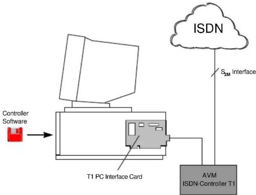
flowchart
graph TD
    A["Controller Software"] --> B["T1 PC Interface Card"]
    B --> C["ISDN"]
    C --> D["S₂M Interface"]
    D --> E["AVM ISDN-Controller T1"]
Fig The AVM ISDN-Controllers T1/T1-B installation
The driver and protocol software is downloaded from the host PC on initialization. The software is oriented after the ISO OSI protocol layer model, and covers Layers 1 to 3 of both the data and signalling channels. This loadable controller software concept permits flexible adaptation to new requirements without installing new hardware or firmware, and forms the basis for flexible adaptation to a variety of purposes and network configurations.
The AVM ISDN-Controller T1/T1-B is equipped with driver software in conformance with the international standard COMMON-ISDN-API Version 2.0 (CAPI 2.0). This driver software supports the protocols X.75 transparent, HDLC transparent, X.25, ISO 8208 (X.25 DTE-DTE) and bit-transparent. As a special feature, the
protocols V.110, V.120 and ISO 3309 are also supported. The ISO 3309 protocol is used primarily in the field of GSM cellular communications, as with Mobile ISDN.
The AVM ISDN-Controller T1/T1-B conforms to the ITU-T I.431 recommendation and supports all 30 B channels and the D channel of the S_2M interface at 64 Kbit/s. On the ISDN D channel, the T1-B supports both the European DSS1 protocol and the national protocol 1TR6. The controller has international approvals for use throughout Europe.
The driver software is available for the operating platforms Novell NetWare, Windows NT and MS-DOS.
Several AVM ISDN-Controllers can be easily combined in one PC. Up to four active AVM ISDN-Controllers can be operated simultaneously.
Installation of the ISDN-Controller hardware and software completely connects the PC to ISDN.

1.3 Package Contents
The product includes:
• AVM ISDN-Controller T1/T1-B
- T1 PC interface card
- Power adapter
- Serial cable to connect the PC interface card to the ISDN-Controller
- Cable to connect the ISDN-Controller to the S_2M interface
- Four driver software diskettes
- One diskette containing the file transfer program Connect2 for DOS
- AVM ISDN-Controller T1/AVM ISDN-Controller T1-B manual
2 Hardware Installation
In order to maintain the full capabilities of the AVM ISDN-Controller T1/T1-B, please observe the following precautions:
- The AVM ISDN-Controller T1/T1-B must not be placed in humid areas.
- The ambient temperature should be between 15^ and 35^ C. The vents in the housing must not be obstructed.
- The AVM ISDN-Controller T1/T1-B should be placed on a firm, stable surface or mounted in a 19-inch equipment rack.

To install the AVM ISDN-Controller T1/T1-B, you must have:
- An ISDN primary rate interface
- An ISDN NT (Network Terminator) including power supply or separate power adapter, installed by your ISDN provider
- A PC with a 486 or higher CPU and a free ISA or EISA bus slot
Examine the contents of your AVM ISDN-Controller T1/T1-B package (see Chapter 1). If any part is missing, contact your dealer immediately.
The hardware installation entails the following steps:
- Installing the PC interface card
- Connecting the cable from the PC interface card to the AVM ISDN-Controller T1/T1-B
- Connecting the cable from the T1 to the NT
- Connecting the T1 power supply
These steps are described in order below. The illustrations are found in Appendix B, Illustrations.
2.1 Installing the PC Interface Card
The AVM ISDN-Controller T1/T1-B is connected to the personal computer through a PC interface card. The PC interface card is a 2/3-length plug-in adapter for the ISA or EISA bus slot. For EISA bus architecture support, the configuration file !AVM0004.CFG is included on the DOS driver disk. Please consult your computer's manual for further information on installing hardware components.

Make sure the I/O address 150 is not in use by any other plug-in adapters in your computer. This is the default I/O address used by the first PC interface card you install.
In order to operate several AVM ISDN-Controller T1/T1-Bs in one computer, you must first assign a unique number to each PC interface card. Read how to do this in Section 2.1.1.
Install the interface card as follows:
- Make sure the PC and any connected peripherals are turned off and their power cords disconnected.
- Open the PC housing. Touch a bare metal part of the chassis to discharge any static electricity from your body.
- Select an appropriate bus slot, remove the back slot cover plate and insert the PC interface card in the slot.
- Screw the back plate of the PC interface card onto the PC chassis.
- Close the computer and plug in the power cord.
This completes the installation of the PC interface card.
2.1.1 Installing Several PC Interface Cards
In order to operate several AVM ISDN-Controller T1/T1-Bs in one computer, you must first assign a unique number to each PC interface card. This number is required so that each card can be addressed and initialized unambiguously. The number for the second and each succeeding ISDN-Controller must be assigned by setting the DIP switches found on the PC interface card (see illustration below.
The DIP switches are numbered from right to left:
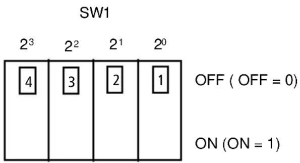
Fig. Positions and significance of the DIP switches
The binary number of the card corresponds to the positions of the DIP switches 1.1 to 1.4. The factory setting is 0. The card number for any given combination of switch settings is calculated as follows:
$$ 2 ^ {3} * \text { SW1.4 } + 2 ^ {2} * \text { SW1.3 } + 2 * \text { SW1.2 } + \text { SW1.1 } $$
where the ON position of each DIP switch has a value of 1 and the OFF position a value of 0.
Before installing PC interface cards for additional ISDN-Controllers, set each card to a number not yet used.
Then proceed to install each card as described above under "Installing the PC Interface Card".
2.2 Connecting the Cable from the PC Interface Card to the AVM ISDN-Controller T1/T1-B
After you have installed the PC interface card, it must be connected to the AVM ISDN-Controller T1/T1-B.

To prevent interference in the high-frequency link, no extensions should be added to the cable supplied.
- Connect the 15-pin sub-D connector of the cable supplied to the upper socket on the back plate of the PC interface card (see Fig. 1). Nothing needs to be connected to the lower socket of the PC interface card.
- Connect the 9-pin sub-D connector of the cable to the 9-pin socket on the ISDN-Controller T1/T1-B (see Fig. 3).
- Secure both connectors by tightening the finger screws.
Now the AVM ISDN-Controller T1/T1-B must be connected to the ISDN network terminator (NT).
2.3 Connecting the Cable from the ISDN-Controller T1 to the NT
This section explains how to connect the cable from the AVM ISDN-Controller T1/T1-B to the ISDN network terminator (NT) installed by the ISDN provider.
The ISDN operator Deutsche Telekom AG uses various types of NTs. For this reason, two different connection procedures are described:
-
Connecting the ISDN-Controller T1 to the NTPM (NT with terminal board)
-
Connecting the ISDN-Controller T1 to the NTPMKU or NTPMGF (NTs with T-shaped mounting plate)
Examine your NT and determine which type it is. In case of doubt, contact your ISDN operator's technical service.
When errors and malfunctions occur at the NT, the S_2M interface may no longer synchronize with the local switch. In this case the switch temporarily disables the PRI. This is indicated by a red LED on the NT. Newer local switches re-enable the interface again automatically.
Such synchronization errors may occur during the AVM ISDN-Controller T1/T1-B connection procedure. If the line is not automatically re-enabled, contact your ISDN operator's technical service.

2.3.1 Connection to the NTPM (NT with Terminal Board)
To ensure that the S_2M interface remains synchronized with the local switch when no terminal equipment is connected, the is NT usually outfitted with wire jumpers between terminals S2M ab/a and S2M ab/b, and between terminals S2M an/a and S2M an/b (“an” = in; “ab” = out). These jumpers must not be removed until the terminal equipment—in this case, the AVM ISDN-Controller T1/T1-B—is operational, i.e. its driver software has been loaded.

- Connect the 9-pin sub-D connector of the cable to the 9-pin socket of the AVM ISDN-Controller T1/T1-B (see Fig. 3 in Appendix B, Illustrations). Secure the connection by tightening the finger screws. Route the 6 meter cable as directly as possible to the NT.
-
Unlock and remove the cover of the NTPM's connection terminals.
-
Remove the back covers of the inserts.
-
Screw the cable onto connector strip X2 on the terminal board.
See Table 1 in Appendix C, Tables, for the pin assignments to connect the AVM ISDN-Control-ler T1/T1-B's cable to the terminal strip.
-
Connect the cable leads to the correct terminals on the terminal strip.
-
Replace the cover over the terminals and lock it.
2.3.2 Connection to the NTPMKU or NTPMGF (NTs with T-shaped Mounting Element)
-
Connect the 9-pin sub-D connector of the cable to the 9-pin socket of the AVM ISDN-Controller T1/T1-B (see Fig. 3 in Appendix B, Illustrations). Secure the connection by tightening the finger screws. Route the 6 meter cable as directly as possible to the NT.
-
Unlock and remove the cover of the NTPMKU or NTPMGF connection terminals.
-
In the NT there is a T-shaped mounting element for the connecting cable (see Fig. 4 in Appendix B, Illustrations). Open it to affix the cable by undoing the screws.
See Table 2 or Table 3, depending on your NT type, in Appendix C, Tables, for the pin assignments to connect the AVM ISDN-Controller T1/T1-B's cable leads to the NTPMKU or NTPMGF terminals.
3 Driver Software Installation
Driver software for the AVM ISDN-Controller T1/T1-B is available for the operating systems Windows NT, Novell NetWare and MS-DOS. This chapter contains a section for each of these platforms describing the installation of the driver software, configuration of the ISDN-Controller, loading and unloading of the driver software, installation of additional controllers and removal of the ISDN-Controller from the system.
Once installed and loaded, the driver provides the application interface COMMON-ISDN-API (CAPI) Version 2.0 to the entire system.
AVM ISDN-Controller driver software undergoes continuous development, and updated drivers are available to you free of charge. You may download the latest drivers for your AVM ISDN-Controller T1/T1-B from the AVM Data Call Center using Connect2 (included) or FRITZ!data. The drivers are also found in the Internet on AVM's FTP server.
AVM Data Call Center
+49-30-399 84 300 (Connect2)
AVM in the Internet
http://www.avm.de/
ftp://ftp.avm.de/
Before you begin the software installation, find out what D-channel protocol your ISDN line uses. In Germany, this may be either the DSS1 (Euro-ISDN) or the 1TR6 protocol. ISDN lines connected after December 1993 are generally DSS1 lines. The 1TR6 protocol is rarely used today.
3.1 MS-DOS Installation
Special drivers are supplied with the ISDN-Controller for use in MS-DOS. Once installed, the driver provides the application interface COMMON-ISDN-API (CAPI) Version 2.0 to all programs (see Appendix A).
Before you begin the installation, make sure the PC interface card(s) have been correctly installed in the computer. Make sure too that the I/O address 150 is not used by any other adapters in the PC. This is the default value used by the first PC interface card installed. If you want to operate several AVM ISDN-Controller T1s/T1-Bs in one computer, you must first assign each PC interface card a unique card number. See the instructions in Chapter 2, "Hardware Installation".
3.1.1 Installing the Driver Software
To install the driver software, proceed as follows:
- Insert the original disk labeled "AVM ISDN-Controller T1, Installation DOS" in your floppy disk drive.
- Change the current directory to your floppy disk drive and then enter
install
to start the installation program. The installation program's sign-on screen appears. You can abort the installation at any time by selecting EXIT or by pressing Ctrl+X. To proceed with the installation, press Return.
- Select the D-channel protocol used by your ISDN line (DSS1 or 1TR6).
Use the Tab key to select the desired entry, then confirm by pressing Return.
- A list of available drives appears. Choose the drive on which the driver software is to be installed.
Use the arrow keys to browse in the list and confirm your choice by pressing Return.
- Next, choose the subdirectory where you want to install the controller software.
The default is \IDRIVER, but this can be changed to any name you wish. Confirm again by pressing Return.
Now the installation routine copies all files to the selected drive and directory. If there is not enough free space on the drive, you will see an error message to this effect.
Otherwise, the installation of the driver software is now complete.
You may now start the AVM ISDN-Controller T1/T1-B.
3.1.2 Loading and Unloading the ISDN-Controller
Initializing the AVM ISDN-Controllers T1/T1-B for operation takes place in two steps:
- Initializing the T1 PC interface card
- Downloading the driver software to the ISDN-Controller T1
| )00#-00#:rev(00#:rebmundobtegt2 | ||||
| TA2 configuration | Fast LINK | Slow LINK | TRA | LINKBUS |
| Base addresses | 0510# | 8510# | - | - |
| Zero wait access | OFF | OFF | - | - |
| Adeepskbi | 20 Mbit/s | 20 Mbit/s | 10 Mbit/s | - |
| Bdeepbi | - | - | 10 Mbit/s | - |
| Interrupt channel | RQ5 | OFF | - | - |
| CON2 LINK | Fast LINK | - | - | - |
| nRs | mejo | - | - | - |
| CON4 LINK | - | Slow LINK | - | - |
| nRs | - | mejo | - | - |
Fast LINK init done Slow LINK init done Total of 3 Processors found
Fig. T1 PC interface card successfully initialized
The PC interface card is initialized by the batch routine T1INIT.BAT.
If the initialization is successful, the following message is displayed on the screen:
Now the driver software for the AVM ISDN-Controller T1 can be loaded.
To do so, run the batch file IBASE.BAT in the driver software installation directory. After successful loading, the green "System" LED on the AVM ISDN-Controller T1/T1-B is lit (see the illustration of the controller's front panel in Appendix B, Illustrations), and the following message is displayed:
| AVM Berlin ISDN-Controller T1 |
| COMMON-ISDN-API Version 2.0 Serial No. xxxxxxxDSS1 / Release xxxxxx Address xxx / IRQ x |
| Add. Service: GSM, V.110 |
Fig. DOS driver sign-on message
To remove the driver software from the AVM ISDN-Controllers T1/T1-B's memory, enter the command:
ibase -
("ibase", space, minus sign) at the DOS prompt.
The "System" LED goes out.
3.1.3 Installing Additional ISDN-Controllers
To operate several AVM ISDN-Controller T1/T1-Bs in one PC, you must edit the files T1INIT.BAT and ISDNLOAD.CFG in the driver installation directory.
T1INIT.BAT
Begin by opening the file T1INIT.BAT in a text editor. Copy and paste the two lines that begin with "@cta2.exe ..." and "@afserver...", so that they now appear twice in the file.
The program CTA2.EXE initializes and configures one PC interface card installed in the computer. It is started with the following command line arguments:
/N#xx indicates the board number
/L#xxxx sets the interface card's I/O address
/l#xx sets the interface card's interrupt level (xx is a hexadecimal number from 08 to 0F; see table)
Note: The value of the command line parameter "/|#" is not itself the interrupt (IRQ) level! To determine the value for this parameter that corresponds to the desired interrupt level, refer to the following table:
| xx#I/nixxfoeulaV | x level | ||||
| Bit 3B | Bit 2B | Bit 1B | Bit 0B | HexeHexH | |
| 1 | 0 | 0 | 0 | 08 | IRQ 3 |
| 1 | 0 | 0 | 1 | 09 | IRQ 5 |
| 1 | 0 | 1 | 0 | 0A | 7 |
| 1 | 0 | 1 | 1 | 0B | IRQ 9 |
| 1 | 1 | 0 | 0 | 0C | IRQ 10 |
| 1 | 1 | 0 | 1 | 0D | IRQ 11 |
| 1 | 1 | 1 | 0 | 0E | IRQ 12 |
| 1 | 1 | 1 | 1 | 0F | IRQ 15 |
| Bits 4 to 7 are not used and set to 0. | |||||
Table Choosing a valid interrupt
The program AFSERVER.EXE runs a test routine on the AVM ISDN-Controller T1/T1-B. Please note that the first argument, “-:I”, is formed with a lower-case L, not with the numeral 1!
Example:
@cta2.exe /N#01 /L#220 /I#0D /SP#05
@afserver -:1 #220 -:b worm.b4
The first command sets the PC interface card with the board number "01" to the I/O address "220" and the interrupt 11. The second command tests the ISDN-Controller that is set to the I/O address 220.
The argument "/SP#xx" sets the serial link speed. The preset value, "05", must not be changed.

ISDNLOAD.CFG
Then open the file ISDNLOAD.CFG (likewise found in the driver software installation directory) in a text editor. Copy and paste the entire section beginning with “[ISDN-Controller-00]”, so that the section appears twice in the file.
In the new copy of the section, increase the controller number in the section header by 1 for each successive ISDN-Controller, then enter the desired I/O address and interrupt level for the additional PC interface card.
Example:
[ISDN-Controller-00]
IO-Adresse=150
Interrupt=5
[ISDN-Controller-01]
IO-Adresse=220
Interrupt=11
Once this has been done, the second controller will also be initialized the next time IBASE.BAT is run.
3.1.4 Removing the Driver Software
To undo the installation of the AVM ISDN-Controller T1/T1-B for MS-DOS, first remove the driver from memory by entering the command ibase -.
Then use the appropriate DOS commands to delete the driver software and the installation directory. If you have added the command ibase to your AUTOEXEC.BAT file, you must also remove it again.
3.2 Windows NT Installation
Installation and configuration of the AVM ISDN-Control-ler T1/T1-B are almost identical for the Windows NT versions 3.51 and 4.0.
Specially developed Windows NT driver software is supplied with the AVM ISDN-Controller B1 PCI. The applications interface COMMON-ISDN-API Version 2.0 supplied supports both 16-bit and 32-bit applications (applications
in DOS windows are not supported, however). See Appendix A for further information about CAPI.
Before you begin the installation, make sure the PC interface card(s) have been correctly installed in the computer. Make sure too that the I/O address 150 is not used by any other adapters in the PC. This is the default value used by the first PC interface card installed. If you want to operate several AVM ISDN-Controller T1s/T1-Bs in one computer, you must first assign each PC interface card a unique card number. See the instructions in Chapter 2, "Hardware Installation".
3.2.1 Installing the Driver Software
To install the driver software, proceed as follows:
- Start Windows NT.
- Insert the original disk labeled "AVM ISDN-Controller T1, Installation Windows NT" in your floppy disk drive.
- Select the "Run" command in the Windows NT 4.0 Start menu (Windows NT 3.51: select the "Run" command in the "File" menu of the Program Manager). In the command line, enter
a:setup
and confirm by clicking on OK.
- The Setup program's sign-on message appears. Click on Continue.
The installation can be canceled at any time by selecting Exit.
-
A list of installed ISDN-Controllers is then displayed. If no AVM ISDN-Controllers are installed yet, the entry "New" (Add an ISDN-Controller) is selected for you. Click on Continue.
-
Enter the name of the directory in which you want to install the ISDN-Controller software.

The default is C:\IDRIVER. You may confirm this or enter any other directory name. When your entry is complete, confirm by clicking on OK.
To return to the previous dialog, click on the Go back button.
-
Select the D-channel protocol used by your ISDN line (DSS1 or 1TR6). Click on the desired entry, then on Continue.
-
In the next dialog you must select the I/O address to be used in the system for the PC interface card.
The first card always uses the I/O address 150.
-
Next, indicate the interrupt level (IRQ) for the PC interface card.
-
Then enter the Card-ID (board number) of the PC interface card. This is the number determined by the DIP switch settings on the card.
If you want to operate several AVM ISDN-Controller T1s/T1-Bs in one computer, you must first set the DIP switches on each PC interface card to a unique card number. See the instructions in Chapter 2, "Hardware Installation".
Now the installation routine copies all files to the specified folder. In the Program Manager or Start menu, you will find a new program group named AVM. This group contains the icons T1 Load, T1 Unload, T1 Setup, T1 Test, T1 Readme and AVM Internet Home Page (Windows NT 4.0 only: this is a link to AVM's Internet site, and requires Internet access and a WWW browser).
Finally, a message box displays the current configuration of the ISDN-Controller. Click on OK to acknowledge and close the window. To complete the installation, Windows NT must now be restarted.
This done, you may start the AVM ISDN-Controller T1/T1-B.
3.2.2 Loading and Unloading the ISDN-Controller
The AVM ISDN-Controller T1/T1-B is installed in Windows NT as a service, and is therefore loaded automatically each time Windows NT is started. This takes place before programs in the Startup group run, so that you may include CAPI-based communications programs in your Startup group if desired.
If you would like to disable automatic loading of the ISDN-Controller, run the T1 Setup program in the AVM group. This program allows you to enable and disable automatic loading, change the D-channel protocol setting and change the controller's interrupt and I/O address settings.
To load the Controller manually, click on T1 Load in the AVM group. When the ISDN-Controller has been loaded, the following message appears:
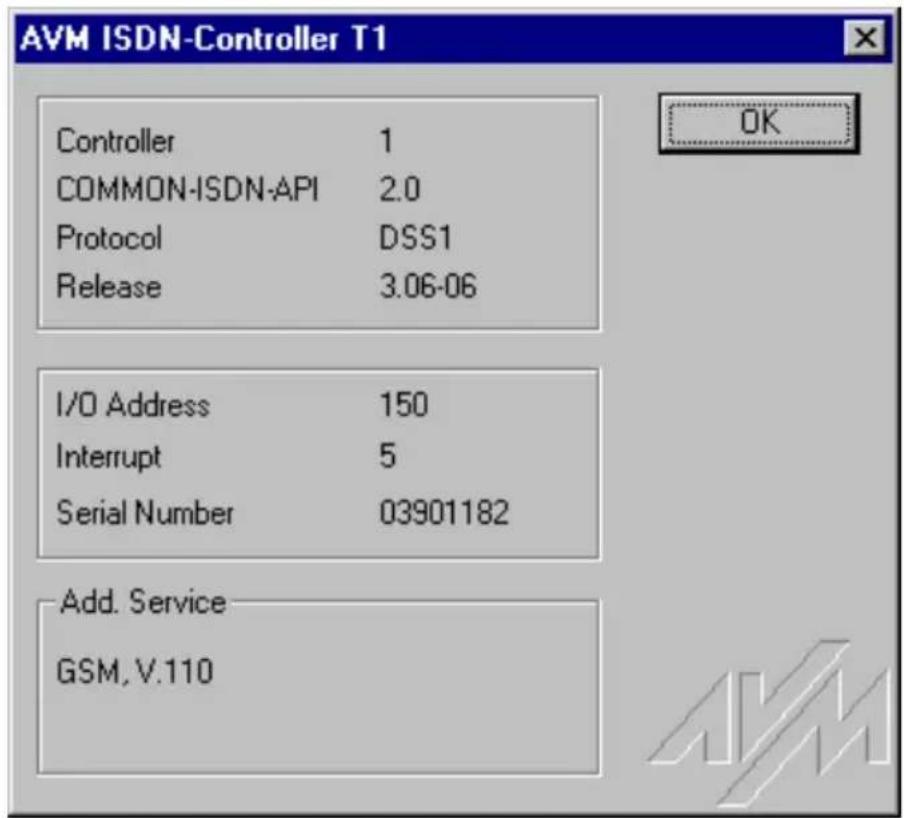
Fig. ISDN-Controller sign-on message in Windows NT
To remove the driver software from memory, click on T1 Unload. A message appears to confirm the operation.
3.2.3 Installing Additional ISDN-Controllers
If you want to add another AVM ISDN-Controller, start the T1 Setup program in the AVM group and select the option New (Add an ISDN-Controller). Follow the program's instructions.
After successful installation, the command T1 Load loads all the Controllers installed.
3.2.4 Removing the Driver Software
To remove the AVM ISDN-Controller T1 from the Windows NT 4.0 system, open the Windows NT Control Panel (Start menu, Settings) and double-click on the Add/Remove Programs applet. The AVM ISDN-Controller T1 appears in the list of installed programs. Select this entry and click on Add/Remove. The deinstallation program starts.
First select the ISDN-Controller that you want to remove. The program then indicates which folder contains the driver software to be deleted. When the deinstallation is finished, you are prompted to restart Windows NT.
To remove the ISDN-Controller from Windows NT 3.51, start the Setup program from the installation CD. Setup reports that an installed ISDN-Controller was detected. Select the option “Deinstallation”, and follow the instructions displayed. (This method can also be used in Windows NT 4.0.)
Only one ISDN-Controller is removed at a time. If you have installed several controllers and want to remove them all, repeat the procedure described above as many times as necessary. You only need to restart Windows NT after the last deinstallation.
3.3 Novell NetWare 3.x and 4.x Installation
Two installation variants are supplied for Novell NetWare 3.x and 4.x: stand-alone CAPI and CAPI Manager. The different installation and configuration procedures are described below.

Before you begin the installation, make sure the PC interface card(s) have been correctly installed in the computer. Make sure too that the I/O address 150 is not used by any other adapters in the PC. This is the default value used by the first PC interface card installed. If you want to operate several AVM ISDN-Controller T1s/T1Bs in one computer, you must first assign each PC interface card a unique card number. See the instructions in Chapter 2, "Hardware Installation".
3.3.1 Installing the Driver Software as a Stand-Alone CAPI
To install the driver software, proceed as follows:
- Insert the original disk labeled "AVM ISDN-Controller T1, Installation CAPI" in your floppy disk drive.
- At the DOS prompt, change the current directory to \DOS on this floppy disk, and enter the command:
install
The installation program creates a directory on drive C: named \T1INIT which contains the initialization program for the PC interface card and a batch routine to start this program. A command sequence to call this batch file is added to the AUTOEXEC.BAT file:
call cd \t1init
call t1init
call cd \
The previous version of AUTOEXEC.BAT is saved as AUTOEXEC.T1.
-
Remove the floppy disk from the drive and restart the computer to initialize the PC interface card.
-
Start up the NetWare operating system by entering
server
at the DOS prompt.
- Load INSTALL.NLM by entering
load install
at the system console. The INSTALL program's "Installation Options" menu appears.
- Select the menu item "Product Options" and press Return.
If you are installing the ISDN-Controller in a NetWare 3.x server, a list of the programs already installed appears.
If you are installing the ISDN-Controller in a NetWare 4.x server, the menu "Other Installation Items/Products" is displayed. In this case, select the item "View/Configure/Remove Installed Products" and press Return. Now the list of installed programs appears.
-
Press Ins (the Insert key) to install a new program.
-
Insert the installation disk (see Step 1) in your floppy disk drive again.
The default path for the installation files is the floppy disk drive A. If you have copied the contents of the installation disk to a hard disk, press F3 and enter the full path name. Confirm your entries by pressing Return.
- In the next step, select "Install on this server" and press Return.
The AVM ISDN-Controller T1/T1-B software is now copied to the SYS:SYSTEM directory.
At the end of the installation process, the Readme file for the AVM ISDN-Controller T1/T1-B is displayed on the screen.
- Press Esc to close the display.
- Press Esc to close the submenus until the menu "Installation Options" is on top.
- Select "Exit" to end INSTALL.
3.3.1.1 Configuring the ISDN-Controller
To configure the ISDN-Controller and its PC interface card, enter the command
load t1setup
at the system console. A list of available ISDN-Controllers with their I/O address and interrupt settings appears. To configure a controller, select it in the list using the arrow keys and then press Return.
To change the I/O address and interrupt level of the PC interface card, move the highlight to the desired parameter, press Return and select the desired value from the pop-up list. The I/O address 150 is the default value for the first PC interface card installed.
Press Esc to close the configuration program. When asked whether you want to save your changes, click on Yes.
3.3.1.2 Loading and Unloading the ISDN-Controller
To load the Controller, enter the command
load capi20
at the system console and press Return. When the ISDN-Controller has been loaded, the following message appears:
| AVM Berlin ISDN-Controller T1 |
| COMMON-ISDN-API Version 2.0 Serial No. xxxxxxxx DSS1 / Release xxxxxx Address xxx / IRQ x |
| Add. Service: GSM, V.110 |
Fig. ISDN-Controller sign-on message in Novell NetWare
The CAPI 2.0 interface is now available to the entire system.
To remove the driver software from memory, enter
load capi20 -d
and press Return. The system acknowledges the command with an appropriate message.
3.3.1.3 Installing Additional ISDN-Controllers
If you want to operate several AVM ISDN-Controller T1s/T1-Bs in one computer, you must first assign each PC interface card a unique card number. See the instructions in Chapter 2, "Hardware Installation".
Enter the command
load t1setup
at the server console. In the list of available ISDN-Controllers, press Ins. A new ISDN-Controller entry is shown with an available I/O address and interrupt level for the PC interface card.
3.3.1.4 Removing the ISDN-Controller
To undo the installation of the AVM ISDN-Controller T1/T1-B in Novell NetWare 3.x or 4.x, proceed as follows:
- At the system console, type
load install
and press Return.
- The INSTALL program's "Installation Options" menu appears. Select the menu item "Product Options" and press Return.
- If you are removing the ISDN-Controller from a NetWare 3.x server, a list of the programs already installed appears.
If you are removing the ISDN-Controller from a NetWare 4.x server, the menu "Other Installation Items/Products" is displayed. In this case, select the item "View/Configure/Remove Installed Products" and press Return. Now the list of installed programs appears.
- Move the highlight to the AVM ISDN-Controller T1 entry and press Del (the Delete key). Select Yes to confirm the action.
3.3.2 Installing the Driver Software as a CAPI.NLM for the Novell CAPI Manager
To install the driver software, proceed as follows:
- Insert the original disk labeled "AVM ISDN-Controller T1, Installation CAPI" in your floppy disk drive.
- At the DOS prompt, change the current directory to \DOS on this floppy disk, and enter the command:
install
The installation program creates a directory on drive C: named \T1INIT which contains the initialization program for the PC interface card and a batch routine to start this program. A command sequence to call this batch file is added to the AUTOEXEC.BAT file:
call cd \t1init
call t1init
call cd \
The previous version of AUTOEXEC.BAT is saved as AUTOEXEC.T1.
-
Remove the floppy disk from the drive and restart the computer to initialize the PC interface card.
-
Start up the NetWare operating system by entering
server
at the DOS prompt.
- Load INSTALL.NLM by entering
load install
at the system console. The INSTALL program's "Installation Options" menu appears.
- Select the menu item "Product Options" and press Return.
If you are installing the ISDN-Controller in a NetWare 3.x server, a list of the programs already installed appears.
If you are installing the ISDN-Controller in a NetWare 4.x server, the menu "Other Installation Items/Products" is displayed. In this case, select the item "View/Configure/Remove Installed Products" and press Return. Now the list of installed programs appears.
-
Press Ins (the Insert key) to install a new program.
-
Insert the installation disk (see Step 1) in your floppy disk drive again.
The default path for the installation files is drive A. If you have copied the contents of the installation disk to a hard disk, press F3 and enter the full path name. Confirm your entries by pressing Return.
- In the next step, select "Install on this server" and press Return.
The AVM ISDN-Controller T1/T1-B software is now copied to the SYS:SYSTEM directory.
At the end of the installation process, the Readme file for the AVM ISDN-Controller T1/T1-B is displayed on the screen.
- Press Esc to close the display.
- Press Esc to close the submenus until the menu "Installation Options" is on top.
- Select "Exit" to end INSTALL.
3.3.2.1 Configuring the ISDN-Controller
To configure the ISDN-Controller and its PC interface card, proceed as follows:
- Enter the command
load inetcfg
at the system console.
- In the “Internetworking Configuration” menu, select the item “Boards”.
A list of installed network adapters and ISDN-Controllers appears.
-
Press Ins to add the AVM ISDN-Controller T1/T1-B to the list.
-
In the list of "Available Drivers", select the driver "WHMSCAPI".
The "Board Configuration" menu appears.
-
Enter a name for the ISDN-Controller, such as "AVMT1-1".
-
Select the menu item "CAPI Board Options" and press Return.
The "WHSMCAPI Board Configuration" menu appears.
-
You are asked whether you want the CAPI driver to be loaded automatically when the server is booted. Select Yes.
-
Now select the CAPI driver "AVMT1" and press Return.
The “CAPI Board Configuration” menu appears.
- Enter the interrupt and I/O address values for the appropriate PC interface card.
The first PC interface card installed uses the I/O address 150.
-
Press Esc twice and save the configuration changes.
-
Press Esc to return to the "Internetworking Configuration" menu.
-
Select the item "Reinitialize system" to activate the new configuration.
The CAPI interface is now available in the system.
3.3.2.2 Installing Additional ISDN-Controllers
If you want to operate several AVM ISDN-Controller T1s/T1-Bs in one computer, you must first assign each PC interface card a unique card number. See the instructions in Chapter 2, "Hardware Installation".
To install additional AVM ISDN-Controller T1s/T1-Bs, perform steps 1 to 11 of the procedure in the preceding section 3.3.2.1, "Configuring the ISDN-Controller".
3.3.2.3 Removing the ISDN-Controller
To undo the installation of the AVM ISDN-Controllers T1/T1-B in Novell NetWare 3.x or 4.x, proceed as follows:
- At the system console, type
load inetcfg
and press Return.
-
In the "Internetworking Configuration" menu that appears, select the item "Boards" and press Return.
-
In the list of installed adapters, select the AVM ISDN-Controller T1/T1-B that you want to remove from the system, and press Del (the Delete key). Select Yes to confirm the action.
-
Press Esc to close the menus and INETCFG.
-
At the system console, enter
load install
and press Return.
-
The INSTALL program's "Installation Options" menu appears. Select the menu item "Product Options" and press Return.
-
If you are installing the ISDN-Controller in a NetWare 3.x server, a list of the programs already installed appears.
If you are installing the ISDN-Controller in a NetWare 4.x server, the menu "Other Installation Items/Products" is displayed. In this case, select the item "View/Configure/Remove Installed Products" and press Return. Now the list of installed programs appears.
- Move the selection to the AVM ISDN-Controller T1 entry and press Del. Select Yes to confirm the action.
4 Troubleshooting
The hardware and software of the AVM ISDN-Controller T1/T1-B are set at the factory to permit trouble-free installation and operation under most conditions.
If problems should arise, first check whether the AVM ISDN-Controller T1/T1-B is correctly installed in your system.
Before you contact your dealer or AVM's support technicians, please follow these troubleshooting procedures:
4.1 The "Power" LED is not lit.
Cause:
The AVM ISDN-Controller T1/T1-B is not being supplied with electrical power.
Possible remedies:
- Make sure the power adapter is firmly plugged into the power outlet.
- Check the power adapter's connection to the AVM ISDN-Controller T1/T1-B. The three-pin connector must be secured by tightening the muff.
- Check the voltage of your power outlet. It should be 230 V ±10% AC at 50 to 60 Hz.
4.2 When the ibase driver is loaded, the message "No processors found" appears.
Cause:
The AVM ISDN-Controller T1 does not respond to your PC.
Possible remedies:
- Check the AVM ISDN-Controller T1/T1-B's power supply. The green "Power" LED must be lit.
- Make sure the cable from the PC interface card to the T1 is connected to the upper socket on the interface card.
- Make sure the cable is not damaged, and that it is not more than 3 meters long.
- Make sure all sub-D connectors are secured with finger screws.
- Make sure the PC interface card is seated snugly in the PC bus slot.
- Verify the settings of the DIP switch block SW 1 and the jumpers J-VCC-2 and J-VCC-4 on the PC interface card. The DIP switch positions must match the board number in the driver software configuration of the given ISDN-Controller. The jumpers must be in the "OFF" position.
4.3 After the ibase driver is loaded, the "System" LED is not lit.
Cause:
The AVM ISDN-Controller T1 does not respond to your PC.
Possible remedies:
- Check the AVM ISDN-Controllers T1/T1-B's power supply. The green "Power" LED must be lit.
- Make sure the cable from the PC interface card to the T1 is connected to the upper socket on the interface card.
-
Make sure the cable is not damaged, and that it is not more than 3 meters long.
-
Make sure all sub-D connectors are secured with finger screws.
- Make sure the PC interface card is seated snugly in the PC bus slot.
- Verify the settings of the DIP switch block SW 1 and the jumpers J-VCC-2 and J-VCC-4 on the PC interface card. The DIP switch positions must match the board number in the driver software configuration of the given ISDN-Controller. The jumpers must be in the "OFF" position.
4.4 The "Sync" LED is not lit.
Cause:
The AVM ISDN-Controller T1 cannot communicate with the ISDN network.
Possible remedies:
- First check whether the “System” LED is lit. If not, then proceed with the instructions in Section 4.3 above, “After the ibase driver is loaded, the “System” LED is not lit”.
- Check the pin assignments of the ISDN NT terminals and your T1 cable leads: see the table in the appendix of this manual.
- Check whether the NT is operational: its green LED must be lit. If it is not, please contact your ISDN provider.
- Make sure your ISDN provider has activated the S interface.
- Check the cable from the AVM ISDN-Controller T1/T1-B to the NT. It must be grounded to the NT, and secured to the AVM ISDN-Controller T1/T1-B by tightening the finger screws on the sub-D connector. Do not use extension cables for this connection.
4.5 The "D Channel" LED is not lit.
Cause:
The AVM ISDN-Controller T1/T1-B cannot establish a D-channel connection.
Possible remedies:
- First check whether the “Sync” LED is lit. If not, proceed with the instructions under Section 4.4, “The ‘Sync’ LED is not lit”, above.
- Make sure your ISDN provider has activated the S interface.
- Check whether the correct D-channel protocol was selected during the driver software installation. To change the D-channel protocol you do not need to repeat the entire software installation. In DOS, change to the directory containing the desired T1 protocol software file (1TR6 or DSS1) and copy the T1-base.t4 file found there to the directory where the driver software was installed. In Windows NT or Novell NetWare, use the Setup program.
- Check the cable from the AVM ISDN-Controller T1/T1-B to the NT. It must be grounded to the NT, and secured to the AVM ISDN-Controller T1/T1-B by tightening the finger screws on the sub-D connector. Do not use extension cables for this connection.
5 Hardware Structure of the AVM ISDN-Controller T1/T1-B
The AVM ISDN-Controller T1/T1-B is designed to process all thirty data channels and the signaling channel of the S_2M interface simultaneously, and can be connected directly to the ISDN network terminator or to an S_2M PBX extension.
The AVM ISDN-Controller T1/T1-B is built in a single-height 19" rack-mount housing. It can be installed either in a 19" equipment rack or as a table-top unit.
The AVM ISDN-Controller T1/T1-B is composed of the following subassemblies:
- the actual ISDN-Controller,
- the link adapter (PC interface card), and
- the power supply.
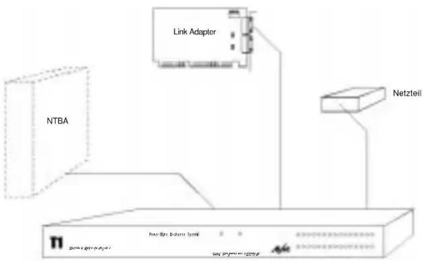
flowchart
graph TD
    A["NTBA"] --> B["Power Sync Database System"]
    C["Link Adapter"] --> B
    D["Netzteil"] --> B
    B --> E["Data Bus"]
    style A fill:#f9f,stroke:#333
    style C fill:#ccf,stroke:#333
    style D fill:#cfc,stroke:#333
Fig. T1 with link adapter and power supply
5.1 The ISDN-Controller T1
The AVM ISDN-Controller T1/T1-B—the core of the full T1 installation—is contained in the 19" housing and includes all the main components for communication between ISDN and the host PC. The ISDN-Controller is connected to the network terminator (NT) and the host PC. A special high-speed interface is used for the PC connection.
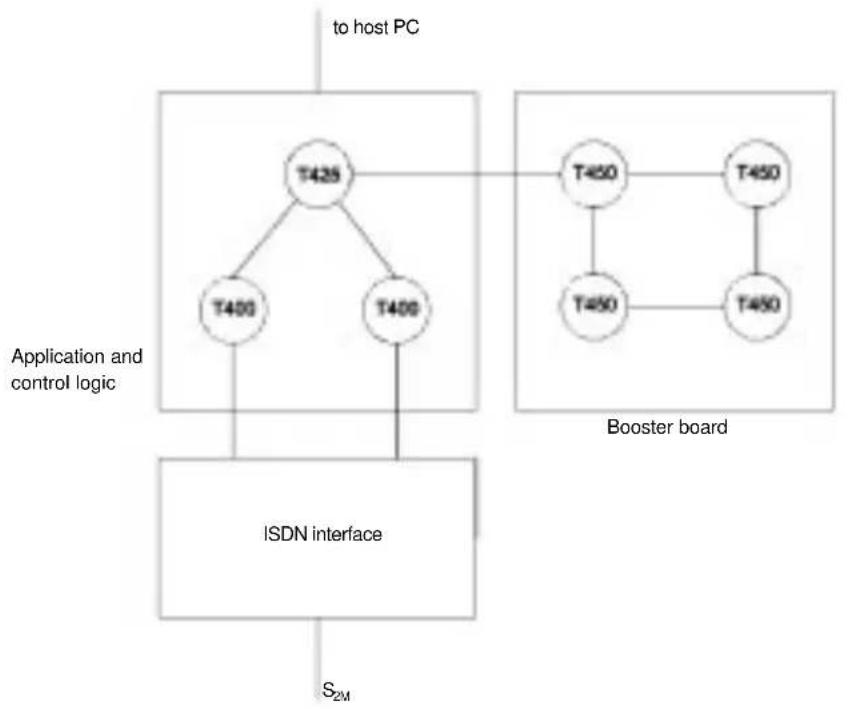
The ISDN-Controller consists of two functional sub-systems. One is the ISDN subsystem, which handles the data transmission to and reception from ISDN and converts the ISDN data stream into a format that the PC can process. The other subsystem comprises the application and control logic.
Data are transferred across the ISDN Primary Rate Interface using a time-multiplex technique and a pseudoternary modified alternate mark inversion (AMI) coding. The multiplex time frame is 256 bits long and divided into 32 slots of eight bits each. Slots 1–15 and 17–31 correspond to the data channels and carry user information. D-channel information is transmitted in Slot 16.
In the T1's ISDN interface, the 30 data channels of the incoming data stream are handled by a Munich32. An HSCX is used for the D channel. The ISDN interface is controlled by the T1's application and control sub-system, which consists of a transputer network of at least three CPUs.
The term “transputer”, a mixture of “transmitter” and “computer”, refers to a processor that combines program execution with fast communication capabilities. A transputer is a RISC CPU equipped with two or four special high-speed interfaces called “links”. This CPU design is ideal for communications applications. The T1’s CPUs are networked together through their links, and one link is used for communication with the host PC.
flowchart
graph TD
    A["Application and control logic"] --> B["T425"]
    A --> C["T400"]
    A --> D["T400"]
    B --> E["ISDN interface"]
    C --> E
    D --> E
    E --> F["S_{2M}"]
    G["Booster board"] --> H["T450"]
    G --> I["T450"]
    G --> J["T450"]
    H --> K["T450"]
    I --> L["T450"]
    J --> M["T450"]
    N["to host PC"] --> A
Fig. Structure of the ISDN-Controller
Two transputers control the B channels and D channel by means of the Munich32 and the HSCX. The third CPU is the applications transputer. Furthermore, the AVM ISDN-Controller T1-B contains another circuit board, called a booster board, in addition to the T1 motherboard. The booster board carries four additional T450 transputers and eight megabytes of RAM, which can be used for applications such as controller-based V.42bis data compression or DTMF functions. The T1 housing can accommodate up to three booster boards.
5.2 The Link Adapter
The link adapter, a plug-in card for the PC's ISA bus slot, forms the interface between the host PC and the T1 controller. Data communication between the ISDN-Controller T1/T1-B and the host PC takes place at a rate of 20 Mbit/s. Up to four link adapter cards can be installed in one PC, so that each host PC can run up to four ISDN-Controller T1s.
5.3 The Power Supply
The external power adapter provides the T1 with 48 volts.
Appendix A: AVM ISDN-Controller T1/T1-B Package Contents
Package Contents
The AVM ISDN-Controller T1 product includes:
- AVM ISDN-Controller T1/T1-B
- T1 PC interface card
- Power adapter
- 1 cable, PC interface card to ISDN-Controller T1
- 1 cable, ISDN-Controller to S _2M interface
- 1 power cord
- 1 diskette, "AVM ISDN-Controller T1, Installation DOS"
- 1 diskette, "AVM ISDN-Controller T1, Installation Windows NT"
- 1 diskette, "AVM ISDN-Controller T1, Installation CAPI"
- This manual
If any of these parts is missing or damaged, please contact your dealer or AVM.
Features and Specifications
AVM ISDN-Controller T1:
- ISDN-Controller for the primary rate interface (S _2M )
- 3 multitasking RISC transputers (20 MIPS)
- 9 MB of RAM on board
- 30 watts maximum power consumption
-
Ambient temperature 15^-35^ C
-
D-channel protocols 1TR6 and DSS1
- B-channel protocols X.75 transparent, HDLC transparent, X.25 (ISO 8208), bit-transparent, V.110, V.120 and ISO 3309
- Modular structure; scalable capacity
- Host system integration through PC bus interface card
- Diagnostics port
- Dimensions: 19" rack format, single height (overall, including connectors: 485 x 370 x 50 mm)
- Certification: CE 0170X
PC interface card:
- Supply voltage: 5V ±5%
- Current load: about 0.4 A
- Dimensions: 189 x 109 mm
Power adapter:
- 100 - 250 VAC
-47 - 63 Hz - 1.1 A max. load at 100 VAC input
- Approvals: UL 1950, CSA 22.2 No. 223, TÜV EN 60950, IEC 950
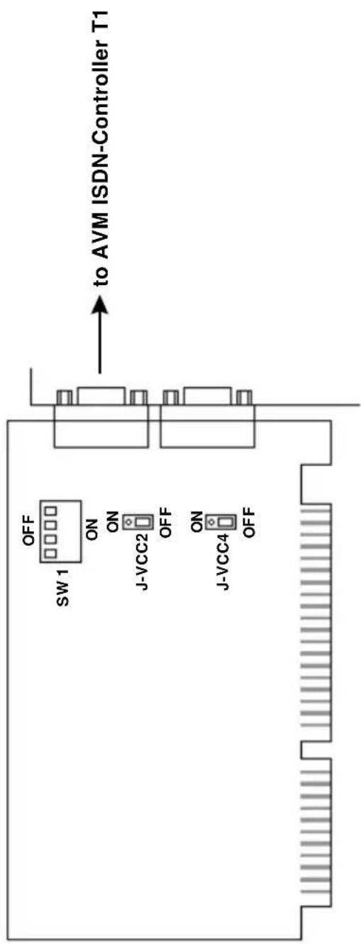
Fig.1: T1 PC interface card
| T1 Primary Rate Interface | Power Sync. D Channel | System | 1 | 2 | 3 | 4 | 5 | 6 | 7 | 8 | 9 | 10 | 11 | 12 | 13 | 14 | 15 | |
| 16 | 17 | 18 | 19 | 20 | 21 | 22 | 23 | 24 | 25 | 26 | 27 | 28 | 29 | 30 |
"Power" LED: Lit when power supply is connected.
"Sync" LED: Lit when the AVM ISDN-Controller T1 is connected to the ISDN network.
“D Channel” LED: Lit when the AVM ISDN-Controller T1 has established a D-channel connection.
“System” LED: Lit when the AVM ISDN-Controller T1 is connected to the PC and the driver software is loaded.
LEDs 1-30: Indicate the active B-channel connections.
Fig. 2: Front panel of the AVM ISDN-Controller T1

Fig. 3: Back panel of the AVM ISDN-Controllers T1
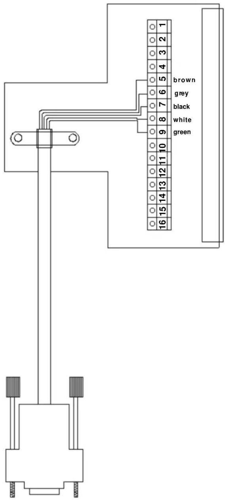
Fig. 4: Pin assignments on the NTPMKU terminal strip
| Terminal strip X2 in NT | T1 cable lead color Function | |
| UK2 ab/b | ||
| UK2 ab/a | ||
| S | ||
| UK2 an/b | ||
| UK2 an/a | ||
| FPE | ||
| FPE | ||
| S2M ab/b white | Receive data S2M a (NT - T1) | |
| S2M ab/a green | Receive data S2M b (NT - T1) | |
| S black Shielding | ||
| S2M an/b brown | Transmit data S2M a (T1 - NT) | |
| S2M an/a gray | Transmit data S2M b (T1 - NT) | |
| S | ||
| T3 ab/b | ||
| T3 ab/a | ||
| -/- UB | ||
| S | ||
| 0V/+UB | ||
Table 1: NTPM pin assignments and T1 cable lead colors
| Terminal strip in NT T1 | cable lead color Function | |
| 1 | +UBatt | |
| 2 Shielding | ||
| 3 | -UBatt | |
| 4 FPE | ||
| 5 brown | Transmit data S2M a (T1 to NT) | |
| 6 gray Transmit data S2M b (T1 to NT) | ||
| 7 black Shielding | ||
| 8 white Receive data S2M a (NT to T1) | ||
| 9 green Receive data S2M b (NT to T1) | ||
| 10 Shielding | ||
| 11 | Transmit data UK2 a | |
| 12 | Transmit data UK2 b | |
| 13 Shielding | ||
| 14 | Receive data UK2 a | |
| 15 | Receive data UK2 b | |
| 16 Shielding | ||
Table 2: NTPMKU pin assignments and T1 cable lead colors
| Terminal strip inNT | T1 cable lead color Function | |
| 1 | + UBatt | |
| 2 Shielding | ||
| 3 | - UBatt | |
| 4 FPE | ||
| 5 brown Transmit data S2M a (T1 - NT) | ||
| 6 gray Transmit data S2M b (T1 - NT) | ||
| 7 black Shielding | ||
| 8 | w | Receive data S2M a (NT - T1) |
| 9 green | Receive data S2M b (NT - T1) | |
| 10 | Shielding | |
Table 3: NTPMGF pin assignments and T1 cable lead colors
- AVM ISDN-Controller T1 Manual
- Copyright 1998 AVM Berlin. All rights reserved.
- Contents
- Introduction to the AVM ISDN-Controller T1/T1-B ....7
- Hardware Installation .... 13
- Driver Software Installation.... 19
- Troubleshooting 39
- Hardware Structure of the AVM ISDN-Controller T1/T1-B...... 43
- Appendix A: AVM ISDN-Controller T1/T1-B Package Contents...... 47
- Appendix B: Illustrations.... 49
- Appendix C: Tables.... 57
- Conventions Used in this Manual
- Graphical Symbols
- Typographical Conventions
- Introduction to the AVM ISDN-Controller T1/T1-B
- The ISDN Network
- ISDN Line Types
- The Primary Rate Interface
- The AVM ISDN-Controller T1/T1-B
- Package Contents
- Hardware Installation
- Installing the PC Interface Card
- Installing Several PC Interface Cards
- Connecting the Cable from the PC Interface Card to the AVM ISDN-Controller T1/T1-B
- Connecting the Cable from the ISDN-Controller T1 to the NT
- Connection to the NTPM (NT with Terminal Board)
- Connection to the NTPMKU or NTPMGF (NTs with T-shaped Mounting Element)
- Driver Software Installation
- AVM Data Call Center
- AVM in the Internet
- MS-DOS Installation
- Installing the Driver Software
- install
- Loading and Unloading the ISDN-Controller
- ibase -
- Installing Additional ISDN-Controllers
- T1INIT.BAT
- ISDNLOAD.CFG
- Removing the Driver Software
- Windows NT Installation
- Installing the Driver Software
- a:setup
- Loading and Unloading the ISDN-Controller
- Installing Additional ISDN-Controllers
- Removing the Driver Software
- Novell NetWare 3.x and 4.x Installation
- Installing the Driver Software as a Stand-Alone CAPI
- server
- load install
- Configuring the ISDN-Controller
- load t1setup
- Loading and Unloading the ISDN-Controller
- load capi20
- load capi20 -d
- Installing Additional ISDN-Controllers
- Removing the ISDN-Controller
- Installing the Driver Software as a CAPI.NLM for the Novell CAPI Manager
- Configuring the ISDN-Controller
- load inetcfg
- Installing Additional ISDN-Controllers
- Removing the ISDN-Controller
- Troubleshooting
- The "Power" LED is not lit.
- Cause:
- Possible remedies:
- When the ibase driver is loaded, the message "No processors found" appears.
- After the ibase driver is loaded, the "System" LED is not lit.
- The "Sync" LED is not lit.
- The "D Channel" LED is not lit.
- Hardware Structure of the AVM ISDN-Controller T1/T1-B
- The ISDN-Controller T1
- The Link Adapter
- The Power Supply
- Appendix A: AVM ISDN-Controller T1/T1-B Package Contents
- Package Contents
- Features and Specifications
- AVM ISDN-Controller T1:
- PC interface card:
- Power adapter:
Brand : AVM
Model : ISDN-Controller T1
Category : ISDN Controller