
TV-IP501W - Surveillance Camera TRENDNET - Free user manual and instructions
Find the device manual for free TV-IP501W TRENDNET in PDF.


| Product Type | Wireless IP Surveillance Camera |
| Model | TV-IP501W |
| Brand | TRENDnet |
| Image Sensor | 1/4-inch CMOS |
| Resolution | 640x480 (VGA) at 30 fps |
| Lens | Fixed, 6mm, F2.0 |
| Night Vision | Up to 10 meters (built-in IR LEDs) |
| Wireless | 802.11b/g Wi-Fi |
| Ethernet | 10/100 Mbps RJ-45 |
| Power | DC 12V, 1A adapter (included) |
| Power Consumption | 6 Watts (max) |
| Dimensions (WxHxD) | 100 x 100 x 110 mm (3.94 x 3.94 x 4.33 in) |
| Weight | 320 g (11.3 oz) |
| Operating Temperature | 0°C to 40°C (32°F to 104°F) |
| Storage Temperature | -20°C to 60°C (-4°F to 140°F) |
| Humidity | 10% to 80% non-condensing |
| Video Compression | MJPEG |
| Audio | Built-in microphone |
| Security | Password protection, IP filtering |
| Mount | Stand or wall mount bracket |
| Included Accessories | Power adapter, CD with software, manual, Ethernet cable, mounting screws |
Frequently Asked Questions - TV-IP501W TRENDNET
User questions about TV-IP501W TRENDNET
0 question about this device. Answer the ones you know or ask your own.
Ask a new question about this device
Download the instructions for your Surveillance Camera in PDF format for free! Find your manual TV-IP501W - TRENDNET and take your electronic device back in hand. On this page are published all the documents necessary for the use of your device. TV-IP501W by TRENDNET.
USER MANUAL TV-IP501W TRENDNET
User's Guide
Table of Contents
About this User's Guide....4
Before you start....4
Packing List....4
System Requirements....5
Default Settings....5
Introduction 6
Features and Benefits....6
Camera Hardware Components....7
Front Components....7
Rear Panel Components....7
Camera Hardware Components 8
LED Indicators 8
Hardware Installation....9
Mounting of Camera 9
Connect Ethernet Cable....10
Connect Power Cable....10
Reset Camera 10
Camera Applications ....11
Security 11
Software - Setup Wizard....12
Launching Setup Wizard for the first time ....12
Browser Configuration....16
Accessing the Camera Video Display 16
Login....17
Web Manager and Live Video Display Page....17
Video – ActiveX ....18
Video – Java....18
Administration - Status Section....20
System Page 20
Video 20
Audio 21
Wireless....21
Network 21
Active Users 22
Configuration Section 23
System 23
Video 24
Audio 24
Wireless....25
Network 26
User....27
Upload....27
E-Mail 28
Tools Section......28
FTP Server Test 29
E-Mail Test 29
Restart....30
Factory Reset ....30
Firmware Upgrade....30
Backup and Restore 31
Software – IPViewPro 2.0....32
Launching IPViewPro 2.0 for the first time ....32
Add a camera for monitoring....33
Display Controls....35
Snapshot, recording and audio controls....35
Live video display controls....36
Camera configuration with IPViewPro....36
Schedule Recording with IPViewPro 2.0....38
Motion Detection and Digital Input ....39
IPViewPro Miscellaneous Options 40
Load Saved Video Files....41
Technical Specifications....43
Limited Warranty 46
About this User's Guide
This user's guide provides instructions on how to install the TV-IP501W Network Camera and use it for camera monitoring applications. Camera monitor applications are accessible through an Ethernet local area network.
Before you start
Please read and make sure you understand all the prerequisites for proper installation of your new Network Camera. Have all the necessary information and equipment on hand before beginning the installation.
Packing List
Open the shipping carton and carefully remove all items. In addition to this Manual, ascertain that you have:
• One TV-IP501W Wireless Internet Camera
One Driver & Utility CD-ROM with User's Guide, IPViewPro 2.0 application and Setup Wizard
• One Quick Installation Guide
• One Ethernet Cable
- One Power Adapter
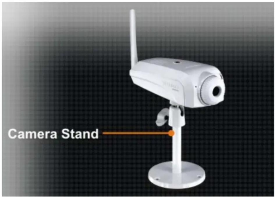
- One Camera Stand
If any of the packaging content is damaged or missing, please contact your dealer immediately. Also keep the box and packaging materials in case you need to ship the unit in the future.

CAUTION: If powering up the camera with DC power, the Camera must be used with the power adapter included with the device.
System Requirements
Computer
• CPU: For Intel x86 compatible CPUs: Intel Pentium IV 2.0Ghz or above
• CPU: For IA64 compatible CPUs: AMD Athlon 64 3000+ and above
- Memory: 1GB or above
• VGA Resolution: 1024 x 768 or above (Independent Display Card recommended)
• 10BASE-T Ethernet or 100BASE-TX Fast Ethernet Network Interface Card
• CD-ROM Drive for Setup Wizard on Installation CD-ROM
- IPViewPro 2.0 Application Users must use Microsoft® Windows®2000, XP or Vista Operating System with Internet Explorer 6.0 or above with DirectX9.0
Network
- Local Area Network: 10Base-T Ethernet or 100Base-TX Fast Ethernet
• Wireless: 802.11b/g wireless adapter

Note: When you connect multiple cameras and monitor their images synchronously, it is recommended to use a high performance system, such as a Pentium 4 & 2.4GHz PC
Default Settings
| Default configuration settings | |
| Username | This is the Username you will be prompted to enter when you access the camera configuration screens using a Web browser. The default Username is admin. |
| Password | This is the Password you will be prompted to enter when you access the configuration windows using a Web browser. The default Password is admin. |
| IP address | This is the IP address you will enter into the Address field of your Web browser to access the camera monitor screen and configuration menus using a Web Browser. The camera uses DHCP for IP settings by default. If a DHCP server is not detected, the default IP address is 192.168.10.30. (Make sure your computer is configured to belong to the 192.168.10.X subnet if using the default IP address of the camera.) |
| Subnet Mask The default subnet mask is 255.255.255.0 | |
Introduction
The TV-IP501W Internet Camera transmits live real-time high-quality Motion-JPEG video through an Ethernet network useful for remote monitoring applications. The live video can be viewed remotely and managed through the network from any computer connected to the network.
Features and Benefits
- Easy to use - The Camera is a standalone system with built-in CPU, no special hardware or software is required. The only requirement you need is the web browser software such as Internet Explorer 6.0 or above. Once you have a valid IP Address, just connect it and you can view the picture and receive sound from your camera. In addition, the camera's stand allows you to adjust the camera for optimal viewing angle.
- Live audio for listen and speaking – The built-in mic is useful for listening for voices in front of the camera.
- Supports variety of platforms - The camera supports TCP/IP networking, SMTP e-mail, JAVA, HTTP and other Internet related protocols. It can be utilized in a mixed operating system environment, including Windows 2000/XP/Vista, Linux and Mac OS. Moreover, it can be integrated easily into other www/ Intranet applications.
- Web configuration - Applying a standard web browser, the administrator can configure and manage the camera directly from its own web page via the Intranet or Internet.
- Remote Utility - The powerful IPViewPro 2.0 application assigns the administrator with a pre-defined user ID and password, allowing the administrator to modify the camera settings from the remote site via Intranet or Internet. When new firmware is available, you can also upgrade remotely over the network for added convenience. Users are also allowed to monitor the image, and take snapshots.
Camera Hardware Components
Front Components

Rear Panel Components
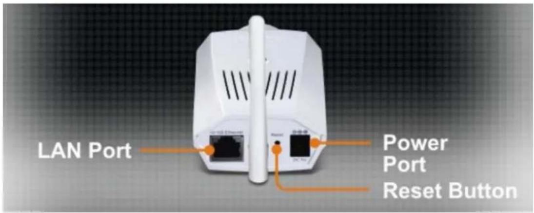
Camera Hardware Components
Below is a summary description of the camera hardware.
| Audio Mic Used to capture sounds | |
| DC 5V | The DC power input connector is located on the back of the camera's rear panel and is labeled DC5V with a single jack socket to supply power to the camera. Power will be generated when the power supply is connected to a wall outlet. |
| Reset | The Reset procedure will be initiated when this button is pressed. The Factory Reset procedure will be initiated when this button is pressed and hold for five seconds. |
| 10/100 Ethernet LAN Port | This RJ-45 connector is used to connect to a 10Base-T Ethernet or to a 100Base-TX Fast Ethernet network. This port supports the N-Way protocol & Auto-MDIX, allowing the camera to automatically detect or negotiate the transmission speed of the network. |
| Camera Stand Connector | It's located on the top and the bottom panel of the camera. This hole is used to connect the camera's stand to the camera by attaching the screw head of the camera stand into the screw hole of the camera. |
LED Indicators
| PWR | This LED indicator lights blue when the camera is powered on. It remains dark when powered off. |
| LNK | A steady orange light indicates that the camera has a good connection to LAN/WLAN. It starts flashing to indicate that the camera is sending and receiving data to and from the LAN. |
Hardware Installation
The camera can be attached to the included stand and placed on a sturdy flat surface or hung from a ceiling or similar flat surface.
Mounting of Camera
Determine the location for the camera and assemble the camera stand. Secure the stand to the flat surface or ceiling with the mounting screws included in the package. When the stand is assembled and firmly attached to flat surface or ceiling, attach the camera. Do not attach network cables or the power cord until the camera is firmly mounted in place.
Connect Ethernet Cable
To connect the camera to your network, connect a Category 5 or better Ethernet cable to the network cable connector located on the camera's rear panel, and then attach it to the network. The Ethernet port will automatically detect and adjust to the speed (10 or 100 Mbps) and polarity (MDI-II or MDI-X) of the connection.

Connect Power Cable
To provide power to the camera using the AC Adapter, connect the AC power adapter to the DC power input connector, also located on the camera's left side panel, and then plug it to the electrical outlet. As with any electrical device, make sure the power source and camera are located in an area where it is not going to get wet or present an electrical hazard.
Reset Camera
A manual reset can be conducted by following the procedure below. The reset button is located on the rear panel of the camera. To reset the system settings to factory defaults, please follow these steps:
- Leave the camera powered on, do not disconnect the power.
- Use a paper clip or similar object to press the reset button and hold. See the Rear Panel picture above to locate the reset button.
- Keep the button pressed about 5 seconds.
- Release the button.
The camera will then automatically reboot itself. Upon restarting the camera loads the factory default configuration settings. The default IP address 192.168.10.30 and subnet mask 255.255.255.0 will be applied unless a DHCP server is actively connected to the network. The administrator's default user name is admin and the password is admin. Use the Setup Wizard shipped with the camera to reconfigure it or access it through the web based management software.
Camera Applications
The camera can be applied in wide variety of applications. With the built-in CPU, it can work as a standalone system that provides a web-based solution transmitting high quality video images and sounds for monitoring purposes. It can be managed remotely, accessed and controlled from any PC desktop over the Intranet or Internet via a web browser. With the easy installation procedure, real-time live images will be available.
Applications:
- Monitoring of local and remote places and objects such as construction sites, hospitals, amusement parks, schools and day-care centers using a web browser.
• View image from IPViewPro. - Configure the camera to save image or send-mail messages with a short video file
![graph TD A["ProView Wireless Internet Camera (TV-IP501W)"] --> B["Internet"] C["ProView PoE Internet Camera (TV-IP501P)"] --> D["24-Port 10/100Mbps Web Smart PoE switch with 4 Gigabit Ports and 2 Mini-GBIC Slots (TPE-224WS)"] B --> E["300Mbps Wireless N ADSL2/2+ Modem Router (TEW-635BRM)"] D --> F["…](/content/2026/05/867483/images/3a24a3e96ed86265801ac88b4bb66c2a5deabf19cc610864948dcb33dce2af1b.jpg)
Security
To ensure the highest security and prevent unauthorized usage of the camera, the administrator has the exclusive privilege to access the System Administration for settings and control requirements to allow users the level of entry and authorize the privileges for all users. The camera supports multi-level password protection. Access to the camera is strictly restricted to define the user who has a "User Name" and "User Password" that is assigned by the administrator. The administrator can release a public user name and password to allow remote users to access the camera.
Software - Setup Wizard
This section describes the how to setup a camera using the Setup Wizard. To install the Setup Wizard on a system running Windows, launch the Setup Wizard on the installation CD-ROM and follow the setup instructions. Once the software is installed, the Setup Wizard utility is ready for use.
Launching Setup Wizard for the first time
To launch the Setup Wizard, click Start > Programs > TRENDnet > Setup Wizard > Setup Wizard
Install Your Camera
- Connect the camera to your LAN using the provided RJ45 cable.
- Connect the AC Power Adapter to the back of the camera and to a live power socket.
- Click Next to continue.
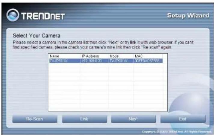
Select Your Camera
The following screen appears showing the cameras that have been found on your network.
- Click on the camera you want to configure.
- Click Next to continue
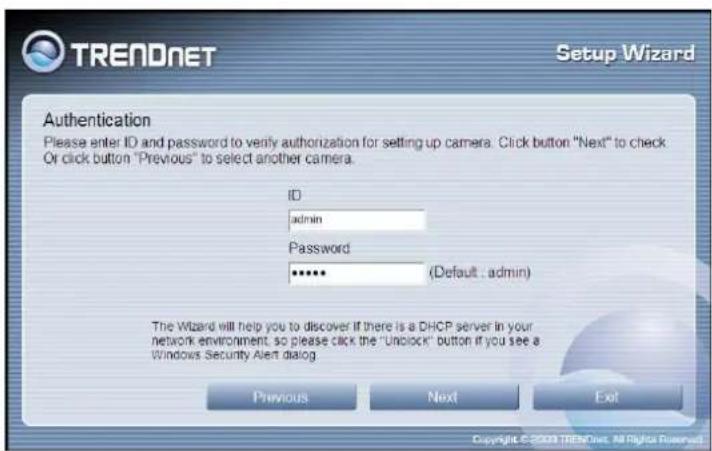
Authentication
On the following screen type in the ID and Password that you will use to configuring the camera settings.
• Type a User ID in the ID field.
- Type the password of the User in the Password field.
- Click Next to continue

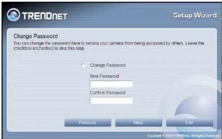
Change Password
The following screen allows you to change the default admin password.
Carry out the following if you want to change the admin password:
- Tick the Change Password checkbox
- Type in a New Password in the New Password field and confirm it in the Confirm Password field
- Click the Next button to proceed to the next Setup window
- If you don't want to change the admin password, leave the checkbox un-ticked and click Next
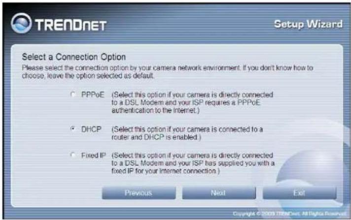
Select a Connection Option
The following window allows you to specify the connection method used by your camera network.
Click the radio button of the network environment your camera is connected to. The available options are:
- PPPoE
• DHCP - Fixed IP
If your connection method is DHCP, click the DHCP radio button and click Next.
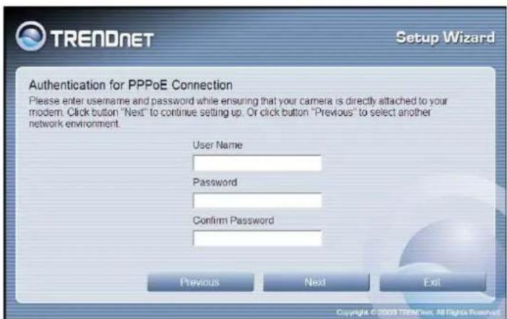
Select a Connection Option- PPPoE If your connection method is PPPoE, click the PPPoE radio button and click Next. The following window appears.
- Type the User Name used to connect to your PPPoE connection in the User Name field.
- Type the Password of the PPPoE User Name in the Password field and confirm it in the Confirm Password field.
- Click Next to proceed to the next setup window
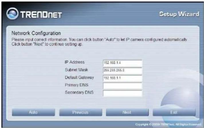
Select a Connection Option- Fixed IP If your connection method is Fixed IP, click the Fixed IP radio button. The following window appears.
- Type in the IP Address, Subnet Mask, Default Gateway, Primary DNS Server IP address and Secondary DNS Server IP Address in the appropriate fields.
- Click Next to proceed to the next setup window.
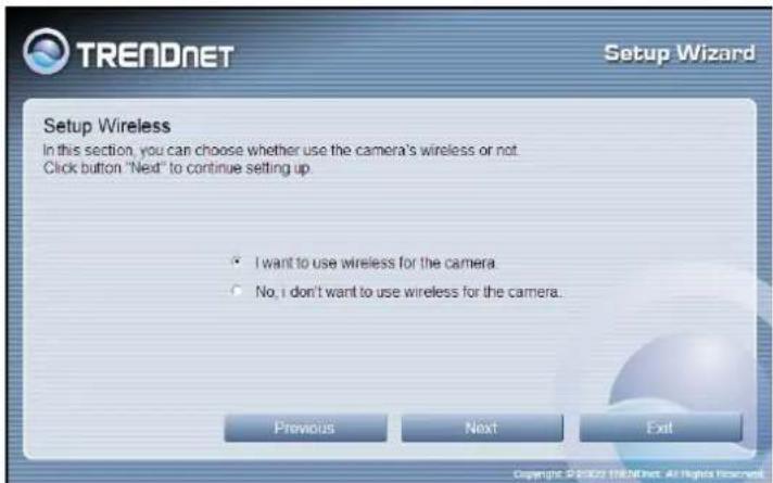
Setup Wireless.
Here you can choose to use wireless for this camera or not.
Manually Setup Wireless.
Here you can choose one of the existing wireless networks in the Available AP option or you can setup the wireless connection manually.
Enter the appropriate SSID, Wireless Mode, Channel, Authentication, Encryption and Key.

Other Settings
The following window allows you to configure additional camera settings.
- Type a name to help you identify the camera in the Camera Name field.
- Set the camera date and time from the Camera Time drop-down menus. To use the time settings from your computer, click the Copy Local Time button.
- Click Next when you have finished
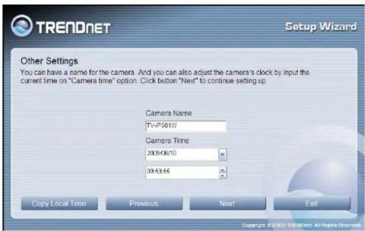
configuring the other settings.
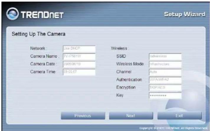
Setting Up The Camera
The following window appears, summarizing the network settings of your camera.
- When you have finished setting up the Camera click the Next button. To make any changes to your Camera settings, click the Previous button.
Camera Restart
The following window appears, indicating that the camera is restarting.

Complete
After the camera has restarted, the following window will appear.
- Click the hyper-link to connect to the camera web interface.
- If you want to setup an additional camera, click the Setup Another Camera button.
- When you have finished, click the Exit button to close the Setup Wizard.

Browser Configuration
The camera is easy to use and manage using a web browser or the IPViewPro 2.0 software to access the camera's live video display, and configuration software. Check and make sure the computer can access and use the camera before placing it in the location where it will be used, especially if it is mounted to a ceiling or other difficult to access area.
For the initial setup, use the Setup Wizard program located on the CD-ROM included with the camera. Use the Setup Wizard to assign an IP address and other network settings. Once the camera has an IP address, follow the instructions below to access the camera's web management interface used to manage the camera and for video display.
Accessing the Camera Video Display
If the camera is used on a network with an active DHCP server, the camera will detect it and obtain an IP address. If you are using the camera on a network with a DHCP server it is necessary to first determine what the IP address of camera is. To do this, follow the instructions in the Quick Installation Guide to launch the Setup Wizard software utility used with the network camera.

NOTE: If your network uses DHCP or has an active DHCP server running, use the Setup Wizard utility on the installation CD-ROM shipped with the camera to first access the camera. Once it is accessed, you can change the IP address or continue to use the DHCP assigned address as preferred.
If your network does not use a DHCP server, the camera will use a default IP address of 192.168.10.30. Use this address to access the web-based management software. Use a web browser and type in http:// followed by the default IP address, 192.168.10.30 in the address bar of the browser and press the Enter key. The URL in the address bar should read: http://192.168.10.30
If the login dialog does not appear, check the proxy server settings on your browser.

NOTE: The wrong proxy server settings on your browser can prevent connection to the web manager. If you are having trouble connecting to the camera, configure the proxy settings to bypass the proxy server or disable use of proxy servers and try to connect again
Login
To access the web manager directly from a computer or on a network without a DHCP server running, use the default IP address of the camera in the browser address entry to access the web manager. Type http://192.168.10.30 in the address bar and press Enter. The login dialog appears when accessing the camera.

Type the default user name "admin", default password "admin" and click on the OK button to access the camera's management interface.
Web Manager and Live Video Display Page
After login you'll be directed to the Home page which will display the last video screenshot.

The camera's web configuration provides two methods of viewing live video display:
• View Video - ActiveX page
• View Video - Java page
Video – ActiveX
To view live video from browser, using ActiveX, click the View Video-ActiveX Mode from the Welcome screen to access the live video feed :
![TREADNET ProView Wireless Internet Camera TV-IP501W Home Administration View Video ActiveX View Video Java View Video - ActiveX Mode TV-IP501W 2009-06-10 09:13:53 Upload Image: ON OFF [OFF] E-mail Image: ON OFF [OFF] Zoom: X1 X2 X3 X4 Audio ON OFF Copyright © 2009 TRENDnet, All Rights Reserved.](/content/2026/05/867483/images/5c43235cdf38119a1c1c1614f0c2e485355d410b4dec0e442bae702901441b6d.jpg)
Video – Java
To view live video from browser, using JAVA, click the View Video-JAVA Mode from Welcome screen to access the live video feed:
![TREADNET ProView Wireless Internet Camera TV-IP501W Home Administration View Video ActiveX View Video Java View Video - Java Mode TV-IP501W 2009-06-10 09:18:32 Upload Image: ON OFF [OFF] E-mail Image: ON OFF [OFF] Zoom +1 +2 +3 +4 Audio ON OFF Copyright © 2009 TREADNet. All Digital Resources.](/content/2026/05/867483/images/3b835f41af05e49341826bd0e7fd3a160a4d7cf2fbf30619219cad048174bf31.jpg)
As you can see, both live video display pages are identical both in look and the controls that are available to manage the display.
| Video Display Control | |
Zoom :  | The Zoom option allows you to digitally zoom in on an object up to 4 times |
Audio :  | The Audio option allows you to toggle Audio mode ON or OFF |
 | The E-mail Image option allows you to turn the image e-mailing option ON or OFF |
 | The Upload Image option allows you to turn the image uploading option ON or OFF |
Administration - Status Section
The Status section displays information about the camera. In the Status section there are pages for System, Video, Audio, Network and Active Users.
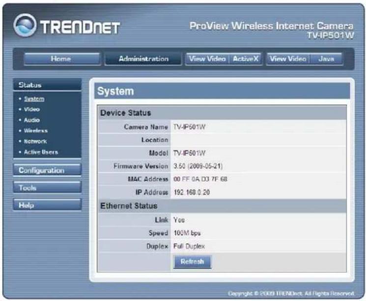
System Page
The System Page display information about the Device Status and Ethernet Status of the camera. Information like the Camera Name, Location, Product Code, Firmware Version, MAC address, IP address, Link Status, Link Speed and Duplex.
Video
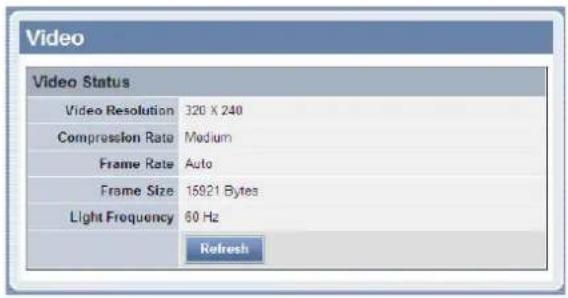
The Video page displays information about the video configuration of the camera like Video Resolution Compression Rate, Frame Rate Frame Size and Light Frequency.
Audio
The Video page displays information about the audio configuration of the camera like Audio Enabled or Disabled, Audio Volume Level, Codec and Sample rate.

Wireless
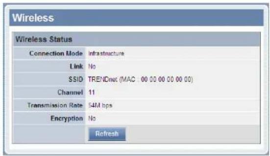
The Wireless page displays information about the wireless configuration of the camera.
Network
The Network page displays the network configuration for the camera like IP Address, Subnet Mask, Default gateway, Primary and Secondary DNS Addresses, Dynamic DNS Enabled or Disabled, Secondary HTTP Port value, UPnP IP Address, FTP Server and E-Mail setup.

Active Users
The Active Users Page displays information about the current active users that are connected to the camera like IP Address, Name, Date/Time and Speed/Throughput.

Configuration Section
In the configuration you can set the configuration for the camera.
System
On the Status Page you can configure general system settings for the camera.
Camera Name:
Configure the camera's display name.
Location:
Configure the camera's display location.
Admin:
Configure the Username and Password for the camera.
LED Control:
Configure the LED display Controls. ON / OFF / DUMMY

Video
On the Video page you can configure the video display settings for the camera.
Video Resolution:
Select between 3 different Video Resolutions.
Compression Rate:
Select between 5 different Compression Rates.
Frame Rate:
Select between 5 different Frame Rates
Choose Auto to let the camera choose the best frame rate needed.
Brightness Control:
Option to manually configure the video brightness.
Contrast Control:
Option to manually configure the video contrast.
Saturation Control:
Option to manually configure the video saturation.
Light Frequency:
Option to configure the light frequency.
Mirror:
Option to flip the live video feed horizontal or vertical.
Anti-Flicker:
Option to enable or disable Anti-Flicker.

Audio
On the Audio page you can configure the audio settings for the camera.
Audio:
Option to enable or disable the Audio settings.
Volume:
Option to set the Volume level.

Wireless
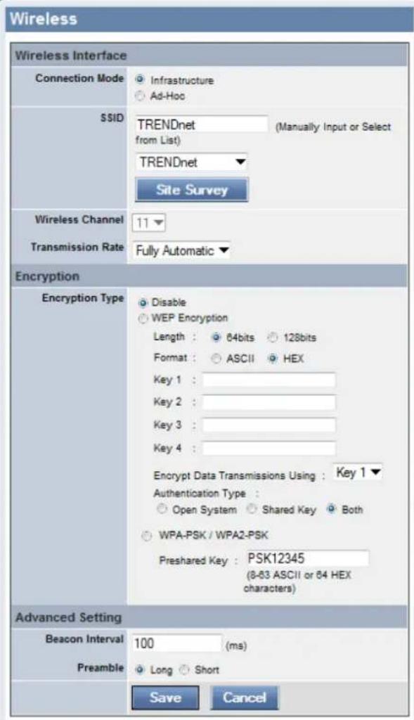
On the Wireless page you can setup the wireless configuration for this camera.
Configuration Mode:
Choose the appropriate wireless configuration mode for this camera. Infrastructure is used if this camera will connect to an existing wireless network. Ad-Hoc is used if this camera will connect directly to a computer wireless.
SSID:
Here enter the SSID for the wireless network.
Wireless Channel:
Here select the correct channel for the wireless. Alternatively you can click Site Survey which will scan for an existing wireless network and enter the above mentioned values automatically.
Transmission Rate:
Here you can choose the transmission rate required.
Encryption Type:
Here you can setup the wireless security required for this camera to connect to the wireless network. You can choose one of 3 options, Disabled, WEP and WPA/WPA2.
Beacon Interval:
Here you can enter the Beacon Interval used for the wireless network.
Preamble:
Here you can choose the preamble used for your wireless network. Long or Short.
Network
Click the Network Setup link to view menus for IP network settings, PPPoE configuration, DDNS and HTTP port configuration.
Fixed IP:
Selecting Static IP Configuration requires you to assign IP information for the camera manually.
Dynamic IP (DHCP):
Selecting DHCP Configuration will cause the camera to obtain an IP address from a local DHCP Server.
PPPoE:
Enable this feature if you want the camera to access the Internet using PPPoE. This requires and PPPoE Username and Password.
DNS IP Address:
Enter DNS IP Addresses used by your ISP here manually.

Enable DDNS:
Enable this feature to use Dynamic DNS. This requires a DDNS account and you must enter the details accordingly here.
Second HTTP Port:
You can enable or disable a secondary http port here. You can change the port number used for the secondary http connection.
UPnP:
Enable this feature to be able to connect to this camera using UPnP
User
On the User page you can create or delete users.
Access Control:
Here you can enable or disable user access control.
Define User:
Here you can add user accounts.
Delete User:
Here you can remove user accounts.

Upload
On this page you can define how the camera uploads images to an FTP server.
Host Address:
Enter the FTP Server's IP Address here.
Port number:
Enter the FTP port used here.
Username:
Enter the FTP Username here.
Password:
Enter the FTP Password here.
Directory Path:
Enter the FTP Directory Path here.
Passive Mode:
Enable or Disable Passive Mode here.
Time Schedule:
You can setup the time schedule here.
Manual Operation:
Setup Manual Operation here.

On this page you can setup the e-mail client configuration that the camera can use.
SMTP Server Address:
Enter the Mail Server IP address here.
SMTP Port Number:
Enter the SMTP port number used here.
Sender's E-Mail Address:
Enter the Sender's e-mail address here:
Recipient's E-Mail Address:
Enter the Recipient's e-mail address here.
User Name:
Enter the mail client username used here.
Password:
Enter the mail client password used here.
Time Schedule:
You can define the time schedule here.
Manual Operation:
You can setup manual operation here.

Tools Section
The Tools section offers many features to test FTP server settings E-Mail settings Firmware upgrade, Backup settings and Restart or Restore options.
FTP Server Test
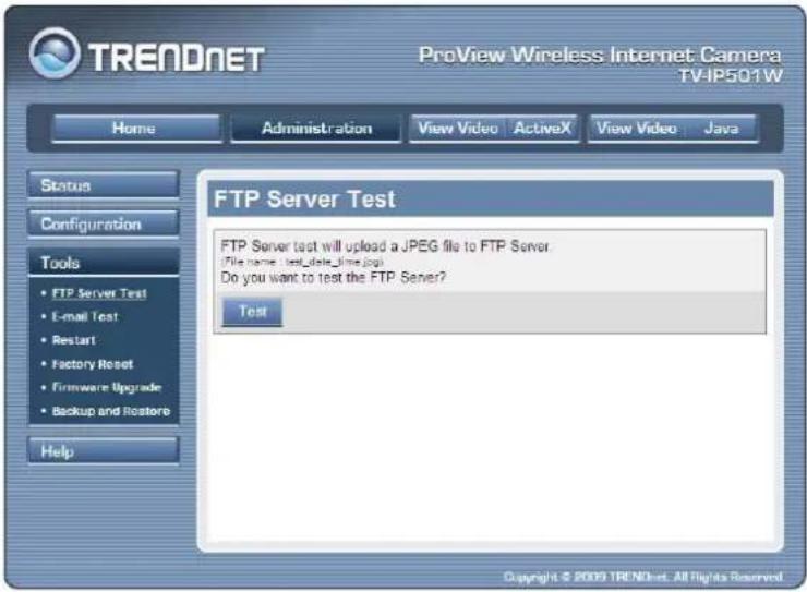
This page will help the user to test if the FTP server settings are setup correctly. It will send a JPEG file to the FTP server called 'test_date_time.jpg' as a test.
E-Mail Test
This page will help the user to test if the e-mail settings are setup correctly. It will send a test mail to the recipient's e-mail address as a test.

Restart
This page gives you the option to manually restart the camera.

Factory Reset
This page gives you the option the factory reset your camera through its web configuration.

Firmware Upgrade
This page gives you the option to upgrade the firmware for the camera. To upgrade the firmware you'll need to download the latest firmware for your camera to your computer, click on the Browse button, navigate to the downloaded file and click Upgrade. This will upgrade the firmware for your camera.

Backup and Restore
This page will allow the user to backup the configuration of the camera to a file that can be saved remotely. It also gives the option to restore the settings from the backup file saved on the hard drive.

Software – IPViewPro 2.0
This section describes the how to setup a camera using the IPViewPro 2.0 camera monitoring software. To install IPViewPro 2.0 on a system running Windows, launch the IPViewPro 2.0 installation software on the installation CD-ROM and follow the setup instructions. Once the software is installed, the IPViewPro 2.0 camera monitoring utility is ready for use. Add up to 32 network cameras to monitor using the software. Additional software, IPViewPro Player software is also installed. The IPViewPro Player is used for playing recorded video from cameras that have been configured to save recorded files.
Launching IPViewPro 2.0 for the first time
To launch IPAddressPro 2.0, click Start > Programs > Network Surveillance > IPAddressPro 2.0. If this is the first time using the software, the menu that appears on is the Add camera menu.
Add a camera for monitoring
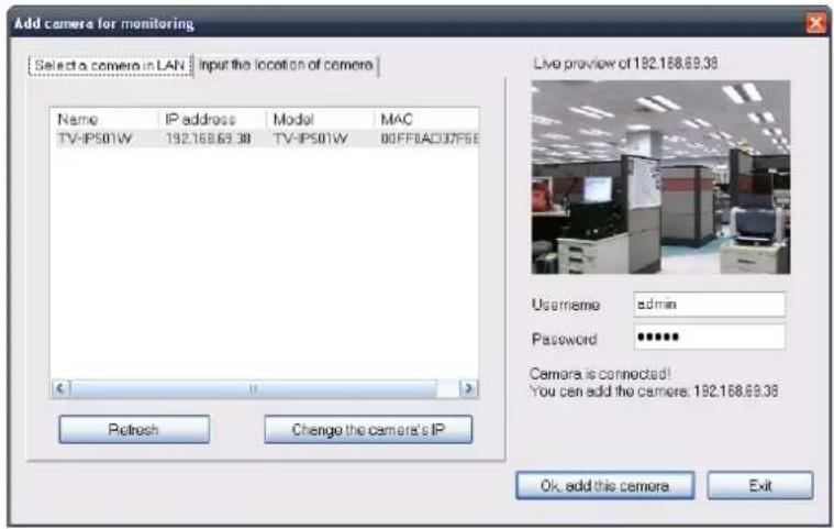
The Add camera menu is presented the first time the LibyaPro 2.0 software is launched. This menu is used to add cameras to the user interface for monitoring. After the first time running the software, this menu can be accessed at anytime from the configuration menus. The configuration menus are described in a later section of this chapter. Notice that the LibyaPro 2.0 software has automatically detected eligible cameras running on the network.
To add a camera to the IPViewPro 2.0 user interface, follow these instructions:
- Check the list of cameras detected by the software, if the camera you want does not appear on the list then clicks the Refresh button to conduct another search. If it still does not appear, check the IP address of the camera and click on the Input the location of camera menu tab and skip ahead to step 2.1

- Select the camera to add from the list, enter the administrator's user name (ID :) and password, a preview of the live video display will appear. Click the OK, add this camera button, a confirmation message informs when the camera is connected and added to the IPViewPro monitoring group. Repeat this procedure for all the cameras being added. Click the Exit button after all the cameras have been added.

If the camera does not appear listed, click the Input the location of camera tab above the list to view a new menu. Enter the IP address or the URL (for example, ipcam.ddns.org) of the camera being added, type the user name and password and click the Preview to verify that a link can be established. The live video of the camera should appear in the Live preview display. If a link cannot be established, run the Setup Wizard software for the camera and verify the correct IP address.
- Once the cameras have been added, they are ready to be used in the main IPViewPro user interface. Close the Add camera menu (click Exit) to go to the main user interface. See below for a description.
IPViewPro 2.0 User Interface

| No. | Item | Description |
| 1 | Live video display area | Display area for single or multiple cameras of live video. Right click on any display area to view a list of quick configure options for that camera including the “Replace camera content ...” option used to change the order of the live video displays for multiple camera views. |
| 2 | Minimize and Exit | Use to minimize IPViewPro interface or exit the program, a confirmation is required to exit. |
| 3 Pan | and Tilt control(Only for cameras equipped with RS-485 controlled pan/tilt motorized mount) | Click directional arrows to move camera in that direction within the limits of the pan and tilt range. The + in the center of the control is used to return to the home or center view as configured for the camera. |
| 4 Snapshot, recording and audio controls | See below for detailed information. | |
| 5 | Live video display controls | See below for detailed information. |
| 6 | Camera configuration menu | See below for detailed information. |
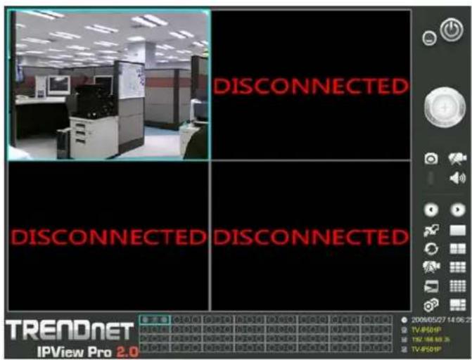
| 7 | Camera status | Use to quickly assess the status of operating cameras. Click on box to select camera display. The status indicators for each camera display recording, motion detection and GP input status. |
| 8 | Camera information | Displays basic information on selected camera. |
Display Controls
The primary display and IPSViewPro control icons are described in detail below. When there are more than one camera displays viewed, one of the displays can be selected for management or additional changes. Simply left click on any display to select it. Notice the border around the display is bright aqua blue, indicating the “selected” status. For example, to go to a single screen display for any one camera, select the camera and click on the single screen display.
Left click on any display to "select" that display for camera management. Right click to view camera management and display options.
Snapshot, recording and audio controls
The still photo camera icon is used to take a snapshot of the selected live video display. The video camera icon is used to begin video recording of the selected live video display. Snapshot and videos files are stored in a default folder on the administrator's system, or in a folder designated by the administrator. The audio controls are represented by a microphone icon to activate the internal mic or the auxiliary audio input (if present), and a speaker icon for the audio output (remote speakers, if present).
Notice that when these functions are activated, the color of the icon changes from white to yellow.

Inactive Active

Live video display controls
Use the video display controls to change the view of the live video display. This is useful for multiple camera application.
![graph TD A["Mouse"] --> B["Click the arrows to manually cycle through the active camera's live displays when using a single camera display screen."] B --> C["Click multi-screen display cons to change the number of camera's displayed at one time. To change the order in which the camera displays appea…](/content/2026/05/867483/images/ef8d6d36480b7e76b15556746ca17e98ba343ceb68e3b4f9bede472964511046.jpg)
Camera configuration with IPViewPro
Access the camera configuration menus by clicking on the gear icon at the bottom of the right hand panel of the IPViewPro user interface. Configuration options include adding and deleting cameras from the display view, configuration of motion detection and digital input with schedules, recording options, email alerts and other network settings.
Adding a Camera
The procedure to add a camera after the initial launch of the software is very similar to the procedure used during the first setup. Follow the instructions below to add cameras.
1. Click the Configuration icon to view the
Camera Setup menu. The top most tab of the menu is the Camera Management tab. A list of active cameras appears on the left half of the menu. Select the camera to be added from the list. Click the Add Camera by IP Address to find the specified IP address or network URL of the camera you want to add.

-
Select the camera to add from the list, enter the administrator's user name (ID :) and password, a preview of the live video display will appear. Click the OK, add this camera button, a confirmation message informs when the camera is connected and added to the IPViewPro 3.0 monitoring group. Repeat this procedure for all the cameras being added. Click the Exit button after all the cameras have been added.
-
The camera added now appears in the Camera List. To launch the web manager for the newly added camera or any camera in the active camera list, select it and click the Browse Selected Camera button.

Removing a Camera
To remove the camera from the list of active:
- Select the camera you want to remove.
- Click Delete Selected Camera.
Note: Any camera display can be removed from the main IPViewPro 2.0 user interface by right clicking on the display screen for the camera and selecting the Remove this Camera option.
Launch Web Manager for Selected Camera
To launch the web-based IP Camera manager for any active camera in the list, simply select it and click the Browse Selected Camera button.
Schedule Recording with IPViewPro 2.0
Use the Camera Setup menu to create schedules for recording and apply the schedules to any camera. Click the Camera Settings tab to view the Schedule Recording menu (the first menu viewed in the
Camera Settings menu tab).
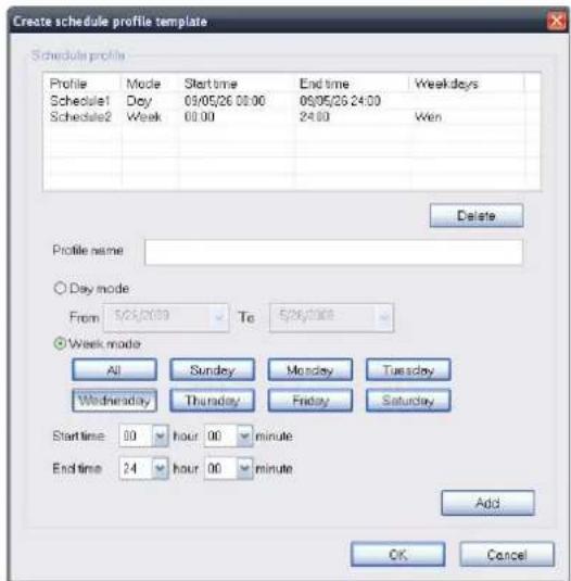
To apply an existing schedule template, click the Select button and choose a schedule from the list of previously created schedule templates. If a new schedule is needed it can be created from the Select Schedule Template menu (See below).

Create Schedule Templates
To make a new schedule template, click the Create Template button to view the Create Schedule Profile menu. Use this menu to create new schedules for recording.

Motion Detection and Digital Input
The Camera Settings menus include Motion Detection setup and Digital Input control. Each menu has the schedule option to apply a schedule for the action taken or always take the specified action.

For Motion Detection, use the Config motion detection area menu to create the area to which it is applicable. Click the Config motion detection area button in the Motion Detection setup menu to view the menu in a new pop up window.
![Config camera motion detecting area[197.168.69.35] Motion detection ✓ Activate MD Sensitivity 80 1~100% Drawing mode ○ Draw area ○ Erase area Select all Clear Save setting Exit](/content/2026/05/867483/images/8429877407bafeb41f2f53dae8817ad2e209be88a4231a8ace673e8b1e71f847.jpg)
IPViewPro Miscellaneous Options
The Other Options available for configuration include Proxy server setup, email notification, scan interval and alert type settings.

Load Saved Video Files
Each camera has a file created automatically for storing video files. These files are normally located in the My Documents folder in Windows. The file folders are named according to the IP address and camera model. For example, 192.168.10.30_TV-IP501W is the name of the file folder for the TV-IP501W using the default (non-DHCP) IP address.
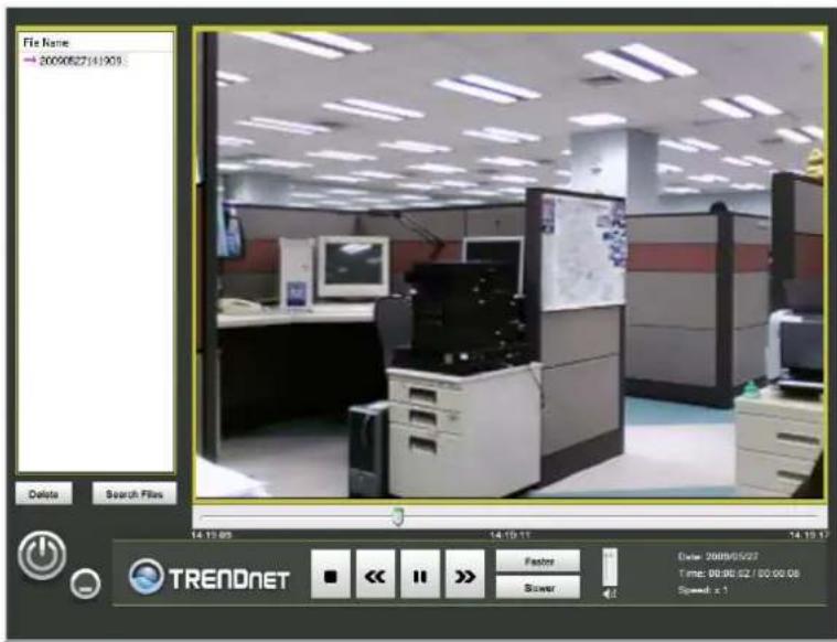
| No. | Item | Description |
| 1 | File list | Video files added to the list are viewed in the order listed. |
| 2 | View Screen | Video files in the list are played here. The progress bar and starting time of the video clip appears beneath the view screen. |
| 3 Add/Delete files from list | Use the Search Files button to add recorded video files. A new menu pops up that is used to find and add files to the list. (See description on next page) | |
| 4 | Playback controls | Standard video playback controls for Stop, Play/Pause, go to next file (>>) or go to previous file (<<) Speed up and Speed down to control speed of playback. The vertical slider control is used for audio volume control. |
To view recorded video files in the IPViewPro Player, it is first necessary to locate and select the files to be viewed and add them to the list. Click the Search Files button in the IPViewPro Player main interface and a new menu appears.
In the new menu, use the Select Camera pull-down menu to choose the video file folder of the camera to be reviewed. Use the Search Time menu to narrow the search to a specific time and date. Finally, the Event selection menu is used to further narrow the scope of the file search for videos triggered by Motion
Detection or a Digital Input device, or files designated for Server Recording. When the search criteria have been defined, click the Search button to place qualified files in the Search list.

Choose the files to be added to the view file list by check marking the individual files or click the Select All button to check mark all files in the Search list, click Add to place the check marked files on the list of files for viewing.
After the files to be viewed have been chosen, click the OK button.
Technical Specifications
| Camera | |
| General | Sensor: 1/4" color CMOS image sensorResolution: up to 640 x 480 pixelsBoard lensFocal length: 4.57mmF/No: F1.9Minimum illumination: 1 LuxFocus depth: 20cm ~ infinityView angle: horizontal: 45 degree, vertical: 35 degree |
| Audio | Built-in microphoneSensitivity: -48dB +/- 3dB (5 meters max)Frequency: 50~16000HzS/N: 50dBCodec: PCM |
| Image & Video Compression: MJPEGExposure/white balance control: automaticResolution: VGA (640x480), QVGA (320x240), QQVGA (160x120) up to 30fps | |
| Hardware | |
| Network | IEEE 802.3u 10/100Mbps Fast Ethernet, Auto-MDIX |
| LED Power, Link | |
| Reset Button Reset settings | |
| Power Consumption | 2.6 watts |
| Power | 5V, 2.5A external power adapter |
| Stand Dimension 128 mm (4.7 in.) | |
| Temperature | Operating: 5°C ~ 40°C (41°F ~ 104°F)Storage: -25°C ~ 50°C (5°F ~ 122°F) |
| Certification CE, FCC | |
Wireless
| Standard | IEEE 802.11b and IEEE 802.11g |
| Frequency | 2.412 ~ 2.4835GHz ISM band |
| Antenna | 1 x 2dBi detachable dipole antennas (Reverse-SMA connector) |
| Data Rate | 802.11b: 11Mbps, 5.5Mbps, 2Mbps and 1Mbps |
| (auto fallback) | 802.11g: 54Mbps, 48Mbps, 36Mbps, 24Mbps, 18Mbps, 12Mbps, 9Mbps and 6Mbps |
| Security | 64/128-bit WEP(ASCII/HEX), WPA-PSK, WPA2-PSK |
| Output Power | 802.11b: 16dBm (typical) |
| 802.11g: 12dBm (typical) | |
| Receiving | 802.11b: -82dBm at 11Mbps |
| Sensitivity | 802.11g: -66dBm at 54Mbps |
| Channel | 1~11 (FCC), 1~13 (ETSI) |
Requirement
| To View Camera | Internet Explorer 6.0 or above, Safari 2.0 or above, Firefox 2.0 or above |
| Browser | and Netscape |
| To Run IPView Pro | Windows XP (32/64-bit), Vista (32/64-bit) |
| Software | |
| IPView Pro 2.0 | Channel: supports up to 32 camerasRecord/Playback/Motion Detection/Audio |
| Network Protocols | IPV4, ARP, TCP, UDP, ICMPDHCP Client, NTP Client, DNS Client, DDNS Client, SMTP Client, FTP ClientHTTP ServerPPPoEUPnP |
Management
| Remote | Remote management supported |
| Backup / Restore | Save/retrieve configuration files |
| Settings | |
| Image | Brightness, contrast, noise reduction, saturation, sharpness, white balance, flip mirror(horizontal/vertical) |
| Video Encoding type: | MJPEGCompression rate: 5 levelsFrame rate: 1, 5, 7, 15, 20, Auto (up to 30fps)Frequency: 50Hz, 60Hz |
| Recording(via Software) | Storage size: 32MB (minimum)Recording type: event based (motion detection), continuous and scheduled |
| Snapshot(via Software) | Trigger event: motion detectionAction: send alert email and/or upload to FTP |
| Access Port HTTP port: 80 (default) | |
| Digital Zoom 4x | |
| Dynamic DNS Yes | |
| Time | Synchronize with NTP server or set time/date manually |
Limited Warranty
TRENDware warrants its products against defects in material and workmanship, under normal use and service, for the following lengths of time from the date of purchase.
TV-IP501W - 3 Years Warranty
AC/DC Power Adapter, Cooling Fan, and Power Supply carry 1 year warranty.
If a product does not operate as warranted above during the applicable warranty period, TRENDware shall, at its option and expense, repair the defective product or part, deliver to customer an equivalent product or part to replace the defective item, or refund to customer the purchase price paid for the defective product. All products that are replaced will become the property of TRENDware. Replacement products may be new or reconditioned.
TRENDware shall not be responsible for any software, firmware, information, or memory data of customer contained in, stored on, or integrated with any products returned to TRENDware pursuant to any warranty.
There are no user serviceable parts inside the product. Do not remove or attempt to service the product by any unauthorized service center. This warranty is voided if (i) the product has been modified or repaired by any unauthorized service center, (ii) the product was subject to accident, abuse, or improper use (iii) the product was subject to conditions more severe than those specified in the manual.
Warranty service may be obtained by contacting TRENDware office within the applicable warranty period for a Return Material Authorization (RMA) number, accompanied by a copy of the dated proof of the purchase. Products returned to TRENDware must be pre-authorized by TRENDware with RMA number marked on the outside of the package, and sent prepaid, insured and packaged appropriately for safe shipment.
WARRANTIES EXCLUSIVE: IF THE TRENDWARE PRODUCT DOES NOT OPERATE AS WARRANTED ABOVE, THE CUSTOMER'S SOLE REMEDY SHALL BE, AT TRENDWARE'S OPTION, REPAIR OR REPLACEMENT. THE FOREGOING WARRANTIES AND REMEDIES ARE EXCLUSIVE AND ARE IN LIEU OF ALL OTHER WARRANTIES, EXPRESSED OR IMPLIED, EITHER IN FACT OR BY OPERATION OF LAW, STATUTORY OR OTHERWISE, INCLUDING WARRANTIES OF MERCHANTABILITY AND FITNESS FOR A PARTICULAR PURPOSE. TRENDWARE NEITHER ASSUMES NOR AUTHORIZES ANY OTHER PERSON TO ASSUME FOR IT ANY OTHER LIABILITY IN CONNECTION WITH THE SALE, INSTALLATION MAINTENANCE OR USE OF TRENDWARE'S PRODUCTS.
TRENDWARE SHALL NOT BE LIABLE UNDER THIS WARRANTY IF ITS TESTING AND EXAMINATION DISCLOSE THAT THE ALLEGED DEFECT IN THE PRODUCT DOES NOT EXIST OR WAS CAUSED BY CUSTOMER'S OR ANY THIRD PERSON'S MISUSE, NEGLECT, IMPROPER INSTALLATION OR TESTING, UNAUTHORIZED ATTEMPTS TO REPAIR OR MODIFY, OR ANY OTHER CAUSE BEYOND THE RANGE OF THE INTENDED USE, OR BY ACCIDENT, FIRE, LIGHTNING, OR OTHER HAZARD.
LIMITATION OF LIABILITY: TO THE FULL EXTENT ALLOWED BY LAW TRENDWARE ALSO EXCLUDES FOR ITSELF AND ITS SUPPLIERS ANY LIABILITY, WHETHER BASED IN CONTRACT OR TORT (INCLUDING NEGLIGENCE), FOR INCIDENTAL, CONSEQUENTIAL, INDIRECT, SPECIAL, OR PUNITIVE DAMAGES OF ANY KIND, OR FOR LOSS OF REVENUE OR PROFITS, LOSS OF BUSINESS, LOSS OF INFORMATION OR DATE, OR OTHER FINANCIAL LOSS ARISING OUT OF OR IN CONNECTION WITH THE SALE, INSTALLATION, MAINTENANCE, USE, PERFORMANCE, FAILURE, OR INTERRUPTION OF THE POSSIBILITY OF SUCH DAMAGES, AND LIMITS ITS LIABILITY TO REPAIR, REPLACEMENT, OR REFUND OF THE PURCHASE PRICE PAID, AT TRENDWARE'S OPTION. THIS DISCLAIMER OF LIABILITY FOR DAMAGES WILL NOT BE AFFECTED IF ANY REMEDY PROVIDED HEREIN SHALL FAIL OF ITS ESSENTIAL PURPOSE.
Governing Law: This Limited Warranty shall be governed by the laws of the state of California.
Some TRENDnet products include software code written by third party developers. These codes are subject to the GNU General Public License ("GPL") or GNU Lesser General Public License ("LGPL").
Go to http://www.trendnet.com/gpl or http://www.trendnet.com Download section and look for the desired TRENDnet product to access to the GPL Code or LGPL Code. These codes are distributed WITHOUT WARRANTY and are subject to the copyrights of the developers. TRENDnet does not provide technical support for these codes. Please go to http://www.gnu.org/licenses/gpl.txt or http://www.gnu.org/licenses/lgpl.txt for specific terms of each license.
Federal Communication Commission Interference Statement:
This equipment has been tested and found to comply with the limits for a Class B digital device, pursuant to Part 15 of the FCC Rules. These limits are designed to provide reasonable protection against harmful interference in a residential installation. This equipment generates uses and can radiate radio frequency energy and, if not installed and used in accordance with the instructions, may cause harmful interference to radio communications. However, there is no guarantee that interference will not occur in a particular installation. If this equipment does cause harmful interference to radio or television reception, which can be determined by turning the equipment off and on, the user is encouraged to try to correct the interference by one of the following measures:
√ Reorient or relocate the receiving antenna.
√ Increase the separation between the equipment and receiver.
√ Connect the equipment into an outlet on a circuit different from that to which the receiver is connected.
√ Consult the dealer or an experienced radio/TV technician for help.
This device complies with Part 15 of the FCC Rules. Operation is subject to the following two conditions:
(1) This device may not cause harmful interference, and
(2) This device must accept any interference received, including interference that may cause undesired operation.
FCC Caution:
Any changes or modifications not expressly approved by the party responsible for compliance could void the user's authority to operate this equipment.
IEEE 802.11b or 802.11g operation of this product in the U.S.A. is firmware-limited to channels 1 through 11.
IMPORTANT NOTE:
FCC Radiation Exposure Statement:
This equipment complies with FCC radiation exposure limits set forth for an uncontrolled environment. This equipment should be installed and operated with minimum distance 20cm between the radiator & your body. This transmitter must not be co-located or operating in conjunction with any other antenna or transmitter.
Product Warranty Registration
Please take a moment to register your product online. Go to TRENDnet's website at http://www.trendnet.com/register
- TABLE OF CONTENTS
- ABOUT THIS USER'S GUIDE
- BEFORE YOU START
- PACKING LIST
- SYSTEM REQUIREMENTS
- COMPUTER
- NETWORK
- DEFAULT SETTINGS
- INTRODUCTION
- FEATURES AND BENEFITS
- CAMERA HARDWARE COMPONENTS
- HARDWARE INSTALLATION
- MOUNTING OF CAMERA
- CONNECT ETHERNET CABLE
- RESET CAMERA
- CAMERA APPLICATIONS
- APPLICATIONS
- SECURITY
- SOFTWARE - SETUP WIZARD
- LAUNCHING SETUP WIZARD FOR THE FIRST TIME
- COMPLETE
- BROWSER CONFIGURATION
- ACCESSING THE CAMERA VIDEO DISPLAY
- LOGIN
- WEB MANAGER AND LIVE VIDEO DISPLAY PAGE
- VIDEO – ACTIVEX
- VIDEO – JAVA
- ADMINISTRATION - STATUS SECTION
- SYSTEM PAGE
- VIDEO
- AUDIO
- WIRELESS
- ACTIVE USERS
- CONFIGURATION SECTION
- SYSTEM
- CAMERA NAME
- LOCATION
- ADMIN
- LED CONTROL
- VIDEO RESOLUTION
- COMPRESSION RATE
- FRAME RATE
- BRIGHTNESS CONTROL
- CONTRAST CONTROL
- SATURATION CONTROL
- LIGHT FREQUENCY
- MIRROR
- ANTI-FLICKER
- VOLUME
- CONFIGURATION MODE
- SSID
- WIRELESS CHANNEL
- TRANSMISSION RATE
- ENCRYPTION TYPE
- BEACON INTERVAL
- PREAMBLE
- FIXED IP
- DYNAMIC IP (DHCP)
- PPPOE
- DNS IP ADDRESS
- ENABLE DDNS
- SECOND HTTP PORT
- UPNP
- USER
- ACCESS CONTROL
- DEFINE USER
- DELETE USER
- UPLOAD
- HOST ADDRESS
- PORT NUMBER
- USERNAME
- PASSWORD
- DIRECTORY PATH
- PASSIVE MODE
- TIME SCHEDULE
- MANUAL OPERATION
- SMTP SERVER ADDRESS
- SMTP PORT NUMBER
- SENDER'S E-MAIL ADDRESS
- RECIPIENT'S E-MAIL ADDRESS
- USER NAME
- TOOLS SECTION
- FTP SERVER TEST
- E-MAIL TEST
- RESTART
- FACTORY RESET
- FIRMWARE UPGRADE
- BACKUP AND RESTORE
- SOFTWARE – IPVIEWPRO 2.0
- LAUNCHING IPVIEWPRO 2.0 FOR THE FIRST TIME
- ADD A CAMERA FOR MONITORING
- DISPLAY CONTROLS
- SNAPSHOT, RECORDING AND AUDIO CONTROLS
- LIVE VIDEO DISPLAY CONTROLS
- CAMERA CONFIGURATION WITH IPVIEWPRO
- ADDING A CAMERA
- CLICK THE CONFIGURATION ICON TO VIEW THE
- REMOVING A CAMERA
- LAUNCH WEB MANAGER FOR SELECTED CAMERA
- SCHEDULE RECORDING WITH IPVIEWPRO 2.0
- MOTION DETECTION AND DIGITAL INPUT
- IPVIEWPRO MISCELLANEOUS OPTIONS
- LOAD SAVED VIDEO FILES
- LIMITED WARRANTY
- FEDERAL COMMUNICATION COMMISSION INTERFERENCE STATEMENT
- FCC CAUTION
- IMPORTANT NOTE
- PRODUCT WARRANTY REGISTRATION
Brand : TRENDNET
Model : TV-IP501W
Category : Surveillance Camera